CHEVY CLASSICS 10 by Randy Irwin 1955-57 COMPLETE FRONT END SUSPENSION REBUILD - PART 1 Parts Needed: 21-29 Front End Rebuild Kit With Coil Springs 21-130 Front End Rebuild Kit With Coil Springs & Factory Power Steering 21-132 Front End Rebuild Kit With Coil Springs & Urethane Bushings 49-240 Coil Spring Compressor 49-331 Detail Gray Spray Paint 49-341 Semi-Gloss Black Chassis Spray Paint 30-148 POR -15 Self Etching Primer 34-73 Control Arm Hardware Kit 21-253 Lower Control Arm Shafts 21-83 Offset Upper Control Arm Shafts 34-170 Idler Arm Bracket Hardware 53-56 Drag Link Dust Cover/Gasket Set 21-64 Drag Link Repair Kit 53-135 Manual Steering Idler Arm 53-361 Manual Steering Drag Link 53-360 Manual Steering Linkage (Drag Link, Idler Arm, Pitman Arm) 53-227 Manual Steering Pitman Arm 49-62 Front Suspension Fork Tool/Splitter Set 49-204 Pitman Arm Puller Tool To order parts call 1-800-456-1957 or visit ClassicChevy.com Tools Needed: Coil Spring Compressor Hammer Tie Rod Splitter Ball Joint Splitter 5/8” Wrench 3/4” Wrench 7/8” Wrench Large Flat Blade Screwdriver Cutters Ratchet 9/16” Socket 5/8” Socket 3/4” Socket There is much more to performance than pure horsepower. Great performance also comes from great control and handling. Eckler’s Classic Chevy has the best value in front suspension kits to make your car handle like it’s on rails. Kits are available with stock height coil springs and rubber control arm bushings, with 2” lowering coil springs or with polyurethane control arm bushings. The 2” lowering coil springs have an 80 lbs higher rating than the original coil springs for a firmer ride, but not a rough ride like cut coil springs can give. We will also discuss changing the front end alignment slightly from original so you can make the car handle far better than it did when it left the factory. In this article we will completely rebuild the front suspension on our 1955 but all procedures are the same for 1955-57. Time Frame: 6-8 hours Randy Irwin - Technical Writer Randy has been involved in the Chevy parts business for over 25 years. He is a wiz- ard at creating, making and modifying custom parts for Chevys. Photo #1a & 1b & 1c: The upper and lower control arms, spindles, coil springs, shocks and all the steering linkage will be removed from the frame to be restored. First we will remove 49-240 21-29 34-73 #1a #1b
Transcript
CHEVY CLASSICS
10
by Randy Irwin
1955-57 COMPLETE FRONT END SUSPENSIONREBUILD - PART 1
Parts Needed:21-29 Front End Rebuild Kit With Coil Springs 21-130 Front End Rebuild Kit With Coil Springs & Factory Power Steering21-132 Front End Rebuild Kit With Coil Springs & Urethane Bushings49-240 Coil Spring Compressor 119.99 113.99 ea.49-331 Detail Gray Spray Paint 14.99 14.24 ea.49-341 Semi-Gloss Black Chassis Spray Paint 15.99 15.19 ea.30-148 POR -15 Self Etching Primer 34.99 33.24 ea.34-73 Control Arm Hardware Kit 43.99 41.79 kit21-253 Lower Control Arm Shafts 109.99 104.49 pr.21-83 Offset Upper Control Arm Shafts 97.99 93.09 pr.34-170 Idler Arm Bracket Hardware 4.99 4.74 set53-56 Drag Link Dust Cover/Gasket Set 8.99 8.54 set21-64 Drag Link Repair Kit 49.99 47.49 kit53-135 Manual Steering Idler Arm 49.99 47.49 kit53-361 Manual Steering Drag Link 109.99 104.49 ea.53-360 Manual Steering Linkage (Drag Link, Idler Arm, Pitman Arm) 53-227 Manual Steering Pitman Arm 54.99 52.24 ea.49-62 Front Suspension Fork Tool/Splitter Set 39.99 37.99 set49-204 Pitman Arm Puller Tool 20.99 19.94 ea.
To order parts call 1-800-456-1957 or visit ClassicChevy.com
Tools Needed: Coil Spring CompressorHammer Tie Rod SplitterBall Joint Splitter5/8” Wrench3/4” Wrench7/8” Wrench
Large Flat Blade ScrewdriverCuttersRatchet 9/16” Socket5/8” Socket3/4” Socket
There is much more to performance than pure horsepower. Greatperformance also comes from great control and handling. Eckler’s ClassicChevy has the best value in front suspension kits to make your car handlelike it’s on rails. Kits are available with stock height coil springs and rubbercontrol arm bushings, with 2” lowering coil springs or with polyurethanecontrol arm bushings. The 2” lowering coil springs have an 80 lbs higherrating than the original coil springs for a firmer ride, but not a rough ridelike cut coil springs can give. We will also discuss changing the front endalignment slightly from original so you can make the car handle far betterthan it did when it left the factory. In this article we will completely rebuildthe front suspension on our 1955 but all procedures are the same for1955-57.
Time Frame: 6-8 hours
Randy Irwin - Technical WriterRandy has been involved in the Chevy
parts business for over 25 years. He is a wiz-ard at creating, making and modifying customparts for Chevys.
Photo #1a & 1b & 1c: The upper and lower control arms,spindles, coil springs, shocks and all the steering linkage will beremoved from the frame to be restored. First we will remove
Photo #2a & 2b & 2c & 2d: On the end of an original non-power steering drag (center) link, there is a large right handthread set screw held in place with a cotter pin. This set screwholds pressure on two springs and seats on each side of theball on the pitman arm. Remove the cotter pin and unscrewthe set screw. With the set screw removed, wiggle the drag linkback and forth. This will push the seats away from the ball onthe pitman arm and allow the drag link to be removed fromthe pitman arm.
Photo #3a & 3b: Theidler arm is bolted to thepassenger side of theframe with two carriagebolts, lock washers andnuts. With the two boltsremoved, the completesteering linkage can beremoved from the frame.
#3a
#3b
#1c
Photo #5a & 5b & 5c: With the tall nut and washers removedfrom the threaded shaft on spring compressor P/N 49-240,feed the shaft up through the hole in the lower control armwhere the lower shock mounts and through the upper shockmount on the upper control arm stand on the frame. Thealuminum pivot plate bolts to the bottom of the lower controlarm using the supplied hardware where the lower shockmounted. Lubricate the lower pivot plate and threads with oilor light grease and install the Delron thick plastic washer, threeflat washers and the tall nut.
#5a
#5b #5c
Photo #4a & 4b & 4c: Toremove the upper andlower control arms, thecoil springs will need tobe compressed to takethe load off the controlarms. The shockabsorber must beremoved to allow instal-
lation of a coil spring compressor. The top of the shock isattached to the upper control arm stand with a 3/8” nut,cupped washers and rubber grommets. The bottom of theshock is attached to the lower control arm with two 5/16”bolts. With the bolts and nut removed, the shock absorber willdrop out through the lower control arm.
#4a
#4b
#4c
#2c
#2d
#2b#2a
the outer tie rod endsfrom the steering arms(knuckles). First removethe cotter pin and nutfrom the tie rod end.Next, using a tie rod endsplitter, disconnect theouter tie rod ends fromthe steering arms on thespindles.
CHEVY CLASSICS
12
Photo #7a & 7b & 7c: With the coil spring compressed, there isno coil spring load on the spindle, ball joints or upper controlarm. Remove the cotter pins and nuts from the upper andlower ball joints and using a ball joint splitter tool remove thespindle.
#7d
Photo #8a & 8b: Using the 1-1/16” wrench, loosen the tall nutallowing the lower control arm to swing down. Once the loadis off the coil spring, the compressor may be removed and thecoil spring itself removed.
#8a #8b
Photo #9a & 9b: Withthe coil springremoved, the upperand lower controlarm may be removedfrom the frame. Theupper control arm isheld to the framewith two 7/16” nutsand the lower controlarm shaft is bolted tothe frame with four7/16” bolts with lockwashers and tall nuts.With the control armsand steering linkageremoved, we areready to start on the
restoration of the front end steering components.
#9a
#9b
Photo #10a & 10b: The original upper and lower ball jointswere riveted to the control arms. Using a sharp chisel andhammer cut the heads of rivets off. Than using a punch, drivethe shaft of the rivet out. If your ball joints have been replacedpreviously, simply remove the bolts that secure them to thecontrol arms.
#10a
#10b
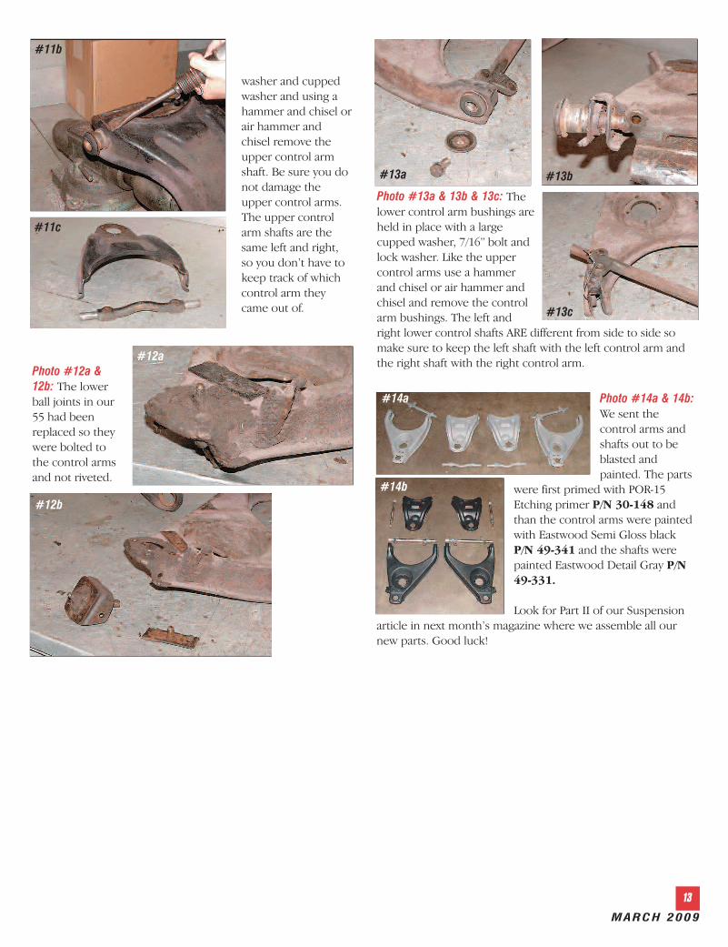
Photo #11a &11b & 11c: Theupper controlarm bushings andshaft are held inplace with a largecupped washer, a3/8” bolt and lockwasher. Removethe bolt, lock#11a
Photo #6: Using a1-1/16” boxed endwrench, tighten thetall nut on the coilspring compressoruntil the uppercontrol arm is nolonger touchingthe upper controlarm bumper onthe frame.
#6
#7a #7b
#7c
MARCH 2009
13
Photo #12a &12b: The lowerball joints in our55 had beenreplaced so theywere bolted tothe control armsand not riveted.
#12a
#12b
Photo #14a & 14b:We sent thecontrol arms andshafts out to beblasted andpainted. The parts
were first primed with POR-15Etching primer P/N 30-148 andthan the control arms were paintedwith Eastwood Semi Gloss blackP/N 49-341 and the shafts werepainted Eastwood Detail Gray P/N49-331.
Look for Part II of our Suspensionarticle in next month’s magazine where we assemble all ournew parts. Good luck!
#14a
#14b
#11b
#11c
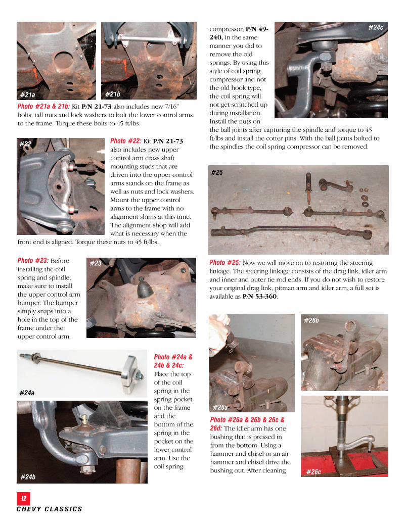
Photo #13a & 13b & 13c: Thelower control arm bushings areheld in place with a largecupped washer, 7/16” bolt andlock washer. Like the uppercontrol arms use a hammerand chisel or air hammer andchisel and remove the controlarm bushings. The left andright lower control shafts ARE different from side to side somake sure to keep the left shaft with the left control arm andthe right shaft with the right control arm.
#13a #13b
#13c
washer and cuppedwasher and using ahammer and chisel orair hammer andchisel remove theupper control armshaft. Be sure you donot damage theupper control arms.The upper controlarm shafts are thesame left and right,so you don’t have tokeep track of whichcontrol arm theycame out of.
CHEVY CLASSICS
10
by Randy Irwin
1955-57 COMPLETE FRONT END SUSPENSIONREBUILD - PART 2
Parts Needed: Catalog price Member price
21-29 Front End Rebuild Kit With Coil Springs 21-130 Front End Rebuild Kit With Coil Springs & Factory Power Steering21-132 Front End Rebuild Kit With Coil Springs & Urethane Bushings49-240 Coil Spring Compressor49-331 Detail Gray Spray Paint 49-341 Semi-Gloss Black Chassis Spray Paint30-148 POR-15 Self Etching Primer34-73 Control Arm Hardware Kit21-253 Lower Control Arm Shafts21-83 Offset Upper Control Arm Shafts34-170 Idler Arm Bracket Hardware53-56 Drag Link Dust Cover/Gasket Set21-64 Drag Link Repair Kit53-135 Standard Steering Idler Arm53-361 Manual Steering Drag Link53-360 Manual Steering Linkage (Drag Link, Idler Arm, Pitman Arm) 53-227 Standard Steering Pitman Arm49-62 Front Suspension Fork Tool/Splitter Set49-204 Pitman Arm Puller Tool
To order parts call 1-800-456-1957 or visit ClassicChevy.com
Tools Needed: Coil Spring CompressorHammer Tie Rod SplitterBall Joint Splitter5/8” Wrench3/4” Wrench7/8” Wrench
Large Flat Blade ScrewdriverCuttersRatchet 9/16” Socket5/8” Socket3/4” Socket
There is much more to performance than pure horsepower. Greatperformance also comes from great control and handling. Eckler’s ClassicChevy has the best value in front suspension kits to make your car handlelike it is on rails. Kits are available with stock height coil springs andrubber control arm bushings, with 2” lowering coil springs or withpolyurethane control arm bushings. The 2” lowering coil springs have an80 lbs higher rating than the original coil springs for a firmer ride but not arough ride like cut coil springs can give. We will also discuss changing thefront end alignment slightly from original so you can make the car handlefar better than it did when it left the factory. In this article we willcompletely rebuild the front suspension on our 1955 but all proceduresare the same for 1955-57.
Time Frame: 6-8 hours
Randy Irwin - Technical WriterRandy has been involved in the Chevy
parts business for over 25 years. He is a wiz-ard at creating, making and modifying customparts for Chevys.
49-240
21-29
34-73
Photo #15a & 15b: The left and right upper control arm shaftsare the same from side to side. There is a casting on the outerside of the shaft that when installed faces right side up.
#15a
#15b
APRIL 2009
11
Photo #16a & 16b: The best way to install new control armbushings is with a hydraulic press and control arm bushingtool. We had a local front end shop install the bushings in theupper and lower control arms. The front suspension bolt kitP/N 34-73 includes all the hardware for the upper and lowercontrol arms. We have installed new cupped washers, lockwashers and bolts in the upper control arm shafts. Leave thebolts loose at this time.
#16a #16b
Photo #19a & 19b: The lowercontrol arm shafts are differentfrom side to side and have afront and rear. The new lowershafts P/N 21-253 include a leftand right shaft, new bushings,cupped washers and bolts. Using a press, install the new lowercontrol arm bushings. Kit P/N 21-73 includes the cuppedwashers, bolts and lock washers for the lower bushings. Leavethe bolt loose at this time.
#19a
#19b
Photo #20a & 20b & 20c:The lower ball joint is boltedto the bottom lower controlarm with six 5/16” X 3/4”bolts, lock washers and nuts.Torque the bolts to 10-12ft/lbs.
#20a #20b
#20c
Photo #17 & Diagram:“Camber” is the term usedto describe how much the front wheel is leaning inward oroutward at the top. After many years of hard use, the frame ona Tri-Five will sag or rotate inward and you may no longer beable to achieve the proper amount of positive camber.
Installing aftermarket tubular control arms or offset shaftswill cure this problem. The Eckler’s Classic Chevy tubularupper control arms P/N 21-185 provide 2-degrees morepositive camber and 5-degrees more caster. The positive casteris only necessary when installing an aftermarket power steeringbox or a rack and pinion unit. To retain the stock upper controlarms but gain more positive camber, offset upper control armshafts can be used in place of the original control arm shafts.The offset shafts P/N 21-83 move the upper control armbushings outward 2-degrees to give you more positive camberadjustment than you will ever need.
Photo #18a & 18b & 18c: Theupper ball joint is installedfrom the top side of the uppercontrol arm. Remove the dustboot from the ball joint using alarge flat blade screwdriver andbolt in place. Bolt the ball jointto the control using thesupplied 5/16” X 3/4” bolts,
nuts and lock washers and torque the bolts to 10-12 ft/lbs. Thedust boot will now install from the bottom of the control arm.A small amount of grease on the lip of the boot will help theboot slide into place.
#17 Diagram
#18c
#18a #18b
CHEVY CLASSICS
12
Photo #26a & 26b & 26c &26d: The idler arm has onebushing that is pressed infrom the bottom. Using ahammer and chisel or an airhammer and chisel drive thebushing out. After cleaning
compressor, P/N 49-240, in the samemanner you did toremove the oldsprings. By using thisstyle of coil springcompressor and notthe old hook type,the coil spring willnot get scratched upduring installation.Install the nuts onthe ball joints after capturing the spindle and torque to 45ft/lbs and install the cotter pins. With the ball joints bolted tothe spindles the coil spring compressor can be removed.
Photo #21a & 21b: Kit P/N 21-73 also includes new 7/16”bolts, tall nuts and lock washers to bolt the lower control armsto the frame. Torque these bolts to 45 ft/lbs.
#21a
Photo #22: Kit P/N 21-73also includes new uppercontrol arm cross shaftmounting studs that aredriven into the upper controlarms stands on the frame aswell as nuts and lock washers.Mount the upper controlarms to the frame with noalignment shims at this time.The alignment shop will addwhat is necessary when the
front end is aligned. Torque these nuts to 45 ft/lbs.
#22
Photo #25: Now we will move on to restoring the steeringlinkage. The steering linkage consists of the drag link, idler armand inner and outer tie rod ends. If you do not wish to restoreyour original drag link, pitman arm and idler arm, a full set isavailable as P/N 53-360.
#25
Photo #23: Beforeinstalling the coilspring and spindle,make sure to installthe upper control armbumper. The bumpersimply snaps into ahole in the top of theframe under theupper control arm.
#23
#21b
#26a
#26b
#26c
Photo #24a &24b & 24c:Place the topof the coilspring in thespring pocketon the frameand thebottom of thespring in thepocket on thelower controlarm. Use thecoil spring
#24a
#24b
#24c
APRIL 2009
13
and painting the armwith Detail Gray we useda hydraulic press to pressthe new bushing into thearm from the bottomflush with the top of theidler arm. The idler armframe bracket is held tothe idler arm with a nutand cotter pin. If youwish to simply replacethe idler arm assemblywith a new one, use P/N 53-145.
Photo #29a & 29b &29c: On the driver’s sidethe drag link attaches tothe ball on the pitmanarm. There are twospacers, two springs,two seats and an endcap. If the seats andsprings are worn,replace them with kitP/N 21-64. The seats fiton each side of thepitman arm ball and thesprings and spacerskeep pressure on theseats holding the draglink to the pitman arm.Install one spacer, springand seat in the end ofthe drag link. Be sure tolubricate all parts with amulti-purpose grease.
Photo #28: With the idler arm and drag link restored bolt theidler arm bracket to the frame. If the original idler arm carriagebolts are bad, new hardware P/N 34-170 is available.
#28
Photo #30a & 30b: Next install the center link to pitman armdust cover P/N 53-56 over the end of the drag link and placethe drag link onto the pitman arm ball.
#30a #30b
Photo #31a & 31b: Now install the second seat, spring andspacer into the outer end of the drag link. The end cap screwsinto the end of the drag link until flush and is held in placewith a 1/8” cotter pin.
#31a #31b
#26d
#27a
#27b
#27c
Photo #27a & 27b & 27c: On the passenger side of the draglink there is a bushing where it attaches to the idler arm. Wehave removed the bushing and cleaned and painted the draglink Detail Gray. Using a hydraulic press, install the newbushing into the drag link from the bottom until flush with thetop of the drag link. The drag link is held to the idler arm witha nut and cotter pin.
#29a
#29b
#29c
CHEVY CLASSICS
14
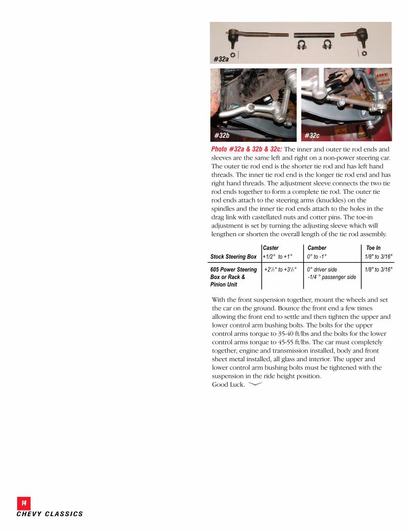
Photo #32a & 32b & 32c: The inner and outer tie rod ends andsleeves are the same left and right on a non-power steering car.The outer tie rod end is the shorter tie rod and has left handthreads. The inner tie rod end is the longer tie rod end and hasright hand threads. The adjustment sleeve connects the two tierod ends together to form a complete tie rod. The outer tierod ends attach to the steering arms (knuckles) on thespindles and the inner tie rod ends attach to the holes in thedrag link with castellated nuts and cotter pins. The toe-inadjustment is set by turning the adjusting sleeve which willlengthen or shorten the overall length of the tie rod assembly.
#32c
#32a
#32b
Caster Camber Toe In
Stock Steering Box +1/2° to +1° 0° to -1° 1/8" to 3/16"
605 Power Steering +21/2° to +31/2° 0° driver side 1/8" to 3/16" Box or Rack & -1/4 ° passenger sidePinion Unit
With the front suspension together, mount the wheels and setthe car on the ground. Bounce the front end a few timesallowing the front end to settle and then tighten the upper andlower control arm bushing bolts. The bolts for the uppercontrol arms torque to 35-40 ft/lbs and the bolts for the lowercontrol arms torque to 45-55 ft/lbs. The car must completelytogether, engine and transmission installed, body and frontsheet metal installed, all glass and interior. The upper andlower control arm bushing bolts must be tightened with thesuspension in the ride height position. Good Luck.