901179 REV D 1/10/19 1969-72 NOVA wo AC EVAP INSTR PG 1 OF 24 an ISO 9001: 2015 Registered Company 18865 Goll St. San Antonio, TX 78266 Phone: 800-862-6658 Sales: [email protected]Tech Support: [email protected]www.vintageair.com 1969-72 Chevrolet Nova without Factory Air Evaporator Kit (561072)
Transcript
901179 REV D 1/10/19 1969-72 NOVA wo AC EVAP INSTR PG 1 OF 24
an ISO 9001: 2015 Registered Company
18865 Goll St. San Antonio, TX 78266 Phone: 800-862-6658
2901179 REV D 1/10/19 1969-72 NOVA wo AC EVAP INSTR PG 2 OF 24
PAGES
Table of Contents
1. COVER 2. TABLE OF CONTENTS 3. PACKING LIST / PARTS DISCLAIMER 4. INFORMATION PAGE 5. WIRING NOTICE 6. ENGINE COMPARTMENT, CONDENSER ASSEMBLY, COMPRESSOR & BRACKETS FIGURE 1 7. PASSENGER COMPARTMENT FIGURE 2 8. KICK PANEL MODIFICATION FIGURES 3 & 4 9. DEFROST DUCT INSTALLATION FIGURE 5 10. FRESH AIR COVER & KICK PANEL FRESH AIR CAP INSTALLATION FIGURES 6, 7, 7a & 7b 11. FIREWALL COVER, EVAPORATOR BRACKET INSTALLATION FIGURES 8 & 912. EVAPORATOR BRACKET INSTALLATION CONT. FIGURE 1013. EVAPORATOR INSTALLATION FIGURES 11, 12 & 12a14. DRAIN HOSE INSTALLATION, LUBRICATING O-RINGS, A/C HOSE INSTALLATION, & MODIFIED A/C HOSE KIT FIGURES 13 & 1415. A/C, HEATER HOSE & HEATER CONTROL VALVE INSTALLATION FIGURE 1516. FINAL STEPS FIGURES 16 & 1717. UNDER DASH LOUVER INSTALLATION FIGURES 18 & 18a18. CONTROL PANEL & DUCT HOSE ROUTING FIGURE 1919. WIRING DIAGRAM20. GEN IV WIRING CONNECTION INSTRUCTIONS21. OPERATION OF CONTROLS22. TROUBLESHOOTING INFORMATION23. TROUBLESHOOTING INFORMATION CONT.24. EVAPORATOR KIT PACKING LIST
3901179 REV D 1/10/19 1969-72 NOVA wo AC EVAP INSTR PG 3 OF 24
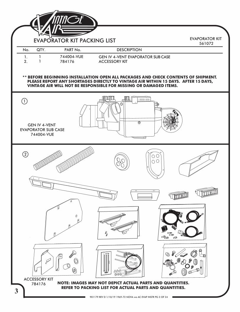
** BEFORE BEGINNING INSTALLATION OPEN ALL PACKAGES AND CHECK CONTENTS OF SHIPMENT. PLEASE REPORT ANY SHORTAGES DIRECTLY TO VINTAGE AIR WITHIN 15 DAYS. AFTER 15 DAYS, VINTAGE AIR WILL NOT BE RESPONSIBLE FOR MISSING OR DAMAGED ITEMS.
EVAPORATOR KIT 561072
EVAPORATOR KIT PACKING LIST
No. QTY. PART No. DESCRIPTION
1.2.
11
744004-VUE784176
GEN IV 4-VENT EVAPORATOR SUB CASEACCESSORY KIT
1
ACCESSORY KIT784176 NOTE: IMAGES MAY NOT DEPICT ACTUAL PARTS AND QUANTITIES.
REFER TO PACKING LIST FOR ACTUAL PARTS AND QUANTITIES.
2
GEN IV 4-VENT EVAPORATOR SUB CASE
744004-VUE
COLD
HOTOFF
HI DASH
DEF
FLR
4901179 REV D 1/10/19 1969-72 NOVA wo AC EVAP INSTR PG 4 OF 24
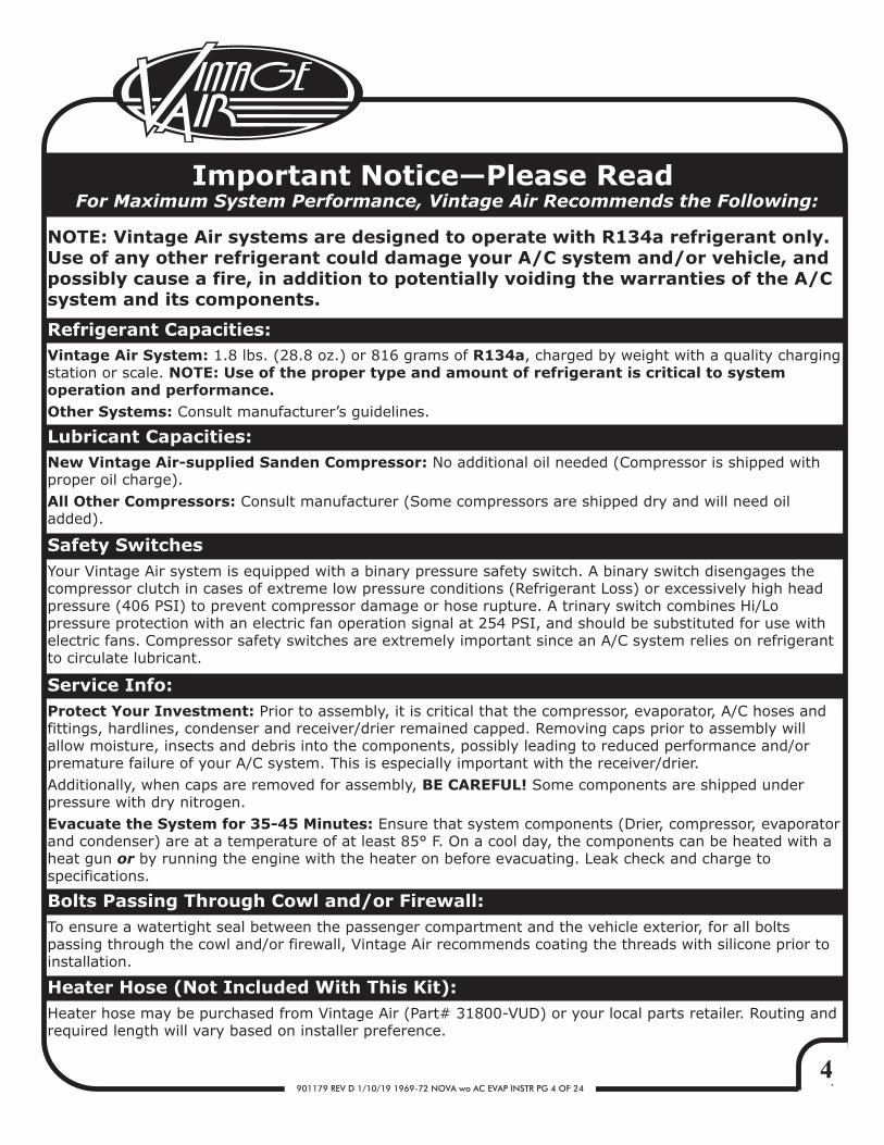
Important Notice—Please ReadFor Maximum System Performance, Vintage Air Recommends the Following:
New Vintage Air-supplied Sanden Compressor: No additional oil needed (Compressor is shipped with proper oil charge).All Other Compressors: Consult manufacturer (Some compressors are shipped dry and will need oil added).
NOTE: Vintage Air systems are designed to operate with R134a refrigerant only. Use of any other refrigerant could damage your A/C system and/or vehicle, and possibly cause a fire, in addition to potentially voiding the warranties of the A/C system and its components.
Refrigerant Capacities:Vintage Air System: 1.8 lbs. (28.8 oz.) or 816 grams of R134a, charged by weight with a quality charging station or scale. NOTE: Use of the proper type and amount of refrigerant is critical to system operation and performance.Other Systems: Consult manufacturer’s guidelines.
Lubricant Capacities:
Safety Switches
Service Info:Protect Your Investment: Prior to assembly, it is critical that the compressor, evaporator, A/C hoses and fittings, hardlines, condenser and receiver/drier remained capped. Removing caps prior to assembly will allow moisture, insects and debris into the components, possibly leading to reduced performance and/or premature failure of your A/C system. This is especially important with the receiver/drier. Additionally, when caps are removed for assembly, BE CAREFUL! Some components are shipped under pressure with dry nitrogen.Evacuate the System for 35-45 Minutes: Ensure that system components (Drier, compressor, evaporator and condenser) are at a temperature of at least 85° F. On a cool day, the components can be heated with a heat gun or by running the engine with the heater on before evacuating. Leak check and charge to specifications.
Your Vintage Air system is equipped with a binary pressure safety switch. A binary switch disengages the compressor clutch in cases of extreme low pressure conditions (Refrigerant Loss) or excessively high head pressure (406 PSI) to prevent compressor damage or hose rupture. A trinary switch combines Hi/Lo pressure protection with an electric fan operation signal at 254 PSI, and should be substituted for use with electric fans. Compressor safety switches are extremely important since an A/C system relies on refrigerant to circulate lubricant.
Bolts Passing Through Cowl and/or Firewall:To ensure a watertight seal between the passenger compartment and the vehicle exterior, for all bolts passing through the cowl and/or firewall, Vintage Air recommends coating the threads with silicone prior to installation.
Heater Hose (Not Included With This Kit):Heater hose may be purchased from Vintage Air (Part# 31800-VUD) or your local parts retailer. Routing and required length will vary based on installer preference.
5901179 REV D 1/10/19 1969-72 NOVA wo AC EVAP INSTR PG 5 OF 24
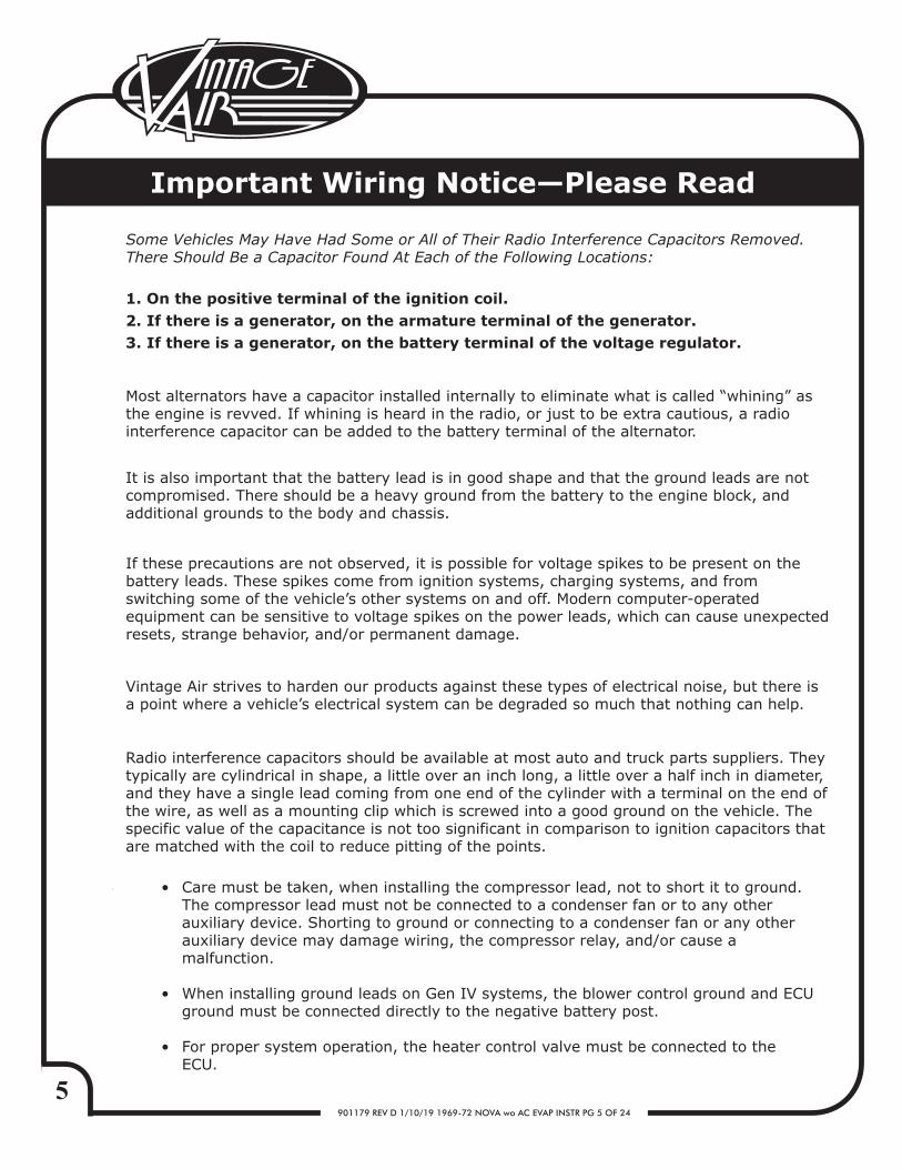
Important Wiring Notice—Please Read
Some Vehicles May Have Had Some or All of Their Radio Interference Capacitors Removed. There Should Be a Capacitor Found At Each of the Following Locations:
1. On the positive terminal of the ignition coil.2. If there is a generator, on the armature terminal of the generator.3. If there is a generator, on the battery terminal of the voltage regulator.
Most alternators have a capacitor installed internally to eliminate what is called “whining” as the engine is revved. If whining is heard in the radio, or just to be extra cautious, a radio interference capacitor can be added to the battery terminal of the alternator.
It is also important that the battery lead is in good shape and that the ground leads are not compromised. There should be a heavy ground from the battery to the engine block, and additional grounds to the body and chassis.
If these precautions are not observed, it is possible for voltage spikes to be present on the battery leads. These spikes come from ignition systems, charging systems, and from switching some of the vehicle’s other systems on and off. Modern computer-operated equipment can be sensitive to voltage spikes on the power leads, which can cause unexpected resets, strange behavior, and/or permanent damage.
Vintage Air strives to harden our products against these types of electrical noise, but there is a point where a vehicle’s electrical system can be degraded so much that nothing can help.
Radio interference capacitors should be available at most auto and truck parts suppliers. They typically are cylindrical in shape, a little over an inch long, a little over a half inch in diameter, and they have a single lead coming from one end of the cylinder with a terminal on the end of the wire, as well as a mounting clip which is screwed into a good ground on the vehicle. The specific value of the capacitance is not too significant in comparison to ignition capacitors that are matched with the coil to reduce pitting of the points.
Care must be taken, when installing the compressor lead, not to short it to ground. The compressor lead must not be connected to a condenser fan or to any other auxiliary device. Shorting to ground or connecting to a condenser fan or any other auxiliary device may damage wiring, the compressor relay, and/or cause a malfunction.
When installing ground leads on Gen IV systems, the blower control ground and ECU ground must be connected directly to the negative battery post.
For proper system operation, the heater control valve must be connected to the ECU.
•
•
•
6901179 REV D 1/10/19 1969-72 NOVA wo AC EVAP INSTR PG 6 OF 24
BEFORE STARTING THE INSTALLATION, CHECK THE FUNCTION OF THE VEHICLE (HORN, LIGHTS,ETC.) FOR PROPER OPERATIONS.
STUDY THE INSTRUCTIONS, ILLUSTRATIONS, & DIAGRAMS.
ENGINE COMPARTMENT
CONDENSER ASSEMBLY & INSTALLATIONREFER TO SEPARATE INSTRUCTIONS INCLUDED WITH THE CONDENSER KIT TO INSTALL THE CONDENSER. BINARY SWITCH INSTALLATION ( REFER TO CONDENSER INSTRUCTIONS)
REFER TO SEPARATE INSTRUCTIONS INCLUDED WITH THE BRACKET KIT TO INSTALL THE COMPRESSOR BRACKET.
COMPRESSOR & BRACKETS
REMOVE THE FOLLOWING:
BATTERY, BATTERY TRAY (RETAIN). DRAIN RADIATOR, REMOVE RADIATOR (RETAIN).TO REMOVE THE BLOWER ASSEMBLY (UNDER HOOD) AND THE AIR DISTRIBUTION SYSTEM (UNDER DASH), THE FACTORY MANUAL INDICATES:REMOVE RIGHT INNER FENDER PANEL. OEM HEATER HOSES (DISCARD). SEE FIGURE 1.OEM HEATER WIRING (DISCARD). SEE FIGURE 1.
FIGURE 1
HEATERHOSES
BATTERYTRAY
OEMBLOWER MOTOR
ASSEMBLY
INNERFENDER PANEL
7901179 REV D 1/10/19 1969-72 NOVA wo AC EVAP INSTR PG 7 OF 24
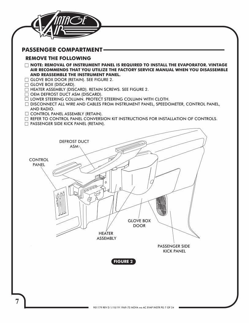
NOTE: REMOVAL OF INSTRUMENT PANEL IS REQUIRED TO INSTALL THE EVAPORATOR. VINTAGE AIR RECOMMENDS THAT YOU UTILIZE THE FACTORY SERVICE MANUAL WHEN YOU DISASSEMBLE AND REASSEMBLE THE INSTRUMENT PANEL.GLOVE BOX DOOR (RETAIN). SEE FIGURE 2. GLOVE BOX (DISCARD).HEATER ASSEMBLY (DISCARD). RETAIN SCREWS. SEE FIGURE 2.OEM DEFROST DUCT ASM (DISCARD).LOWER STEERING COLUMN. PROTECT STEERING COLUMN WITH CLOTH.DISCONNECT ALL WIRE AND CABLES FROM INSTRUMENT PANEL, SPEEDOMETER, CONTROL PANEL,AND RADIO.CONTROL PANEL ASSEMBLY (RETAIN).REFER TO CONTROL PANEL CONVERSION KIT INSTRUCTIONS FOR INSTALLATION OF CONTROLS.PASSENGER SIDE KICK PANEL (RETAIN).
CONTROLPANEL
GLOVE BOXDOOR
HEATER ASSEMBLY
FIGURE 2
PASSENGER COMPARTMENTREMOVE THE FOLLOWING
DEFROST DUCTASM
PASSENGER SIDE KICK PANEL
8901179 REV D 1/10/19 1969-72 NOVA wo AC EVAP INSTR PG 8 OF 24
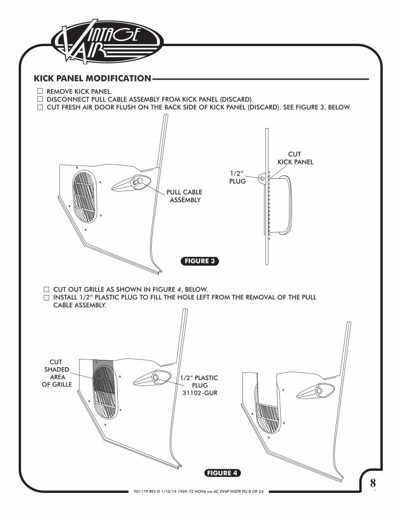
KICK PANEL MODIFICATION
FIGURE 3
FIGURE 4
REMOVE KICK PANEL. DISCONNECT PULL CABLE ASSEMBLY FROM KICK PANEL (DISCARD).CUT FRESH AIR DOOR FLUSH ON THE BACK SIDE OF KICK PANEL (DISCARD). SEE FIGURE 3, BELOW.
CUT OUT GRILLE AS SHOWN IN FIGURE 4, BELOW.INSTALL 1/2” PLASTIC PLUG TO FILL THE HOLE LEFT FROM THE REMOVAL OF THE PULL CABLE ASSEMBLY.
CUT KICK PANEL
1/2” PLUG
PULL CABLE ASSEMBLY
CUT SHADED
AREAOF GRILLE
1/2” PLASTIC PLUG
31102-GUR
9901179 REV D 1/10/19 1969-72 NOVA wo AC EVAP INSTR PG 9 OF 24
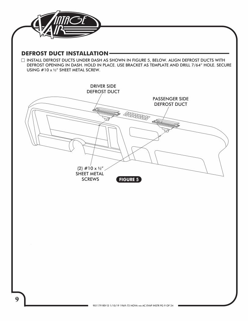
INSTALL DEFROST DUCTS UNDER DASH AS SHOWN IN FIGURE 5, BELOW. ALIGN DEFROST DUCTS WITHDEFROST OPENING IN DASH. HOLD IN PLACE. USE BRACKET AS TEMPLATE AND DRILL 7/64” HOLE. SECUREUSING #10 x ½” SHEET METAL SCREW.
DRIVER SIDEDEFROST DUCT
(2) #10 x ½”SHEET METAL
SCREWS
PASSENGER SIDEDEFROST DUCT
DEFROST DUCT INSTALLATION
FIGURE 5
10901179 REV D 1/10/19 1969-72 NOVA wo AC EVAP INSTR PG 10 OF 24
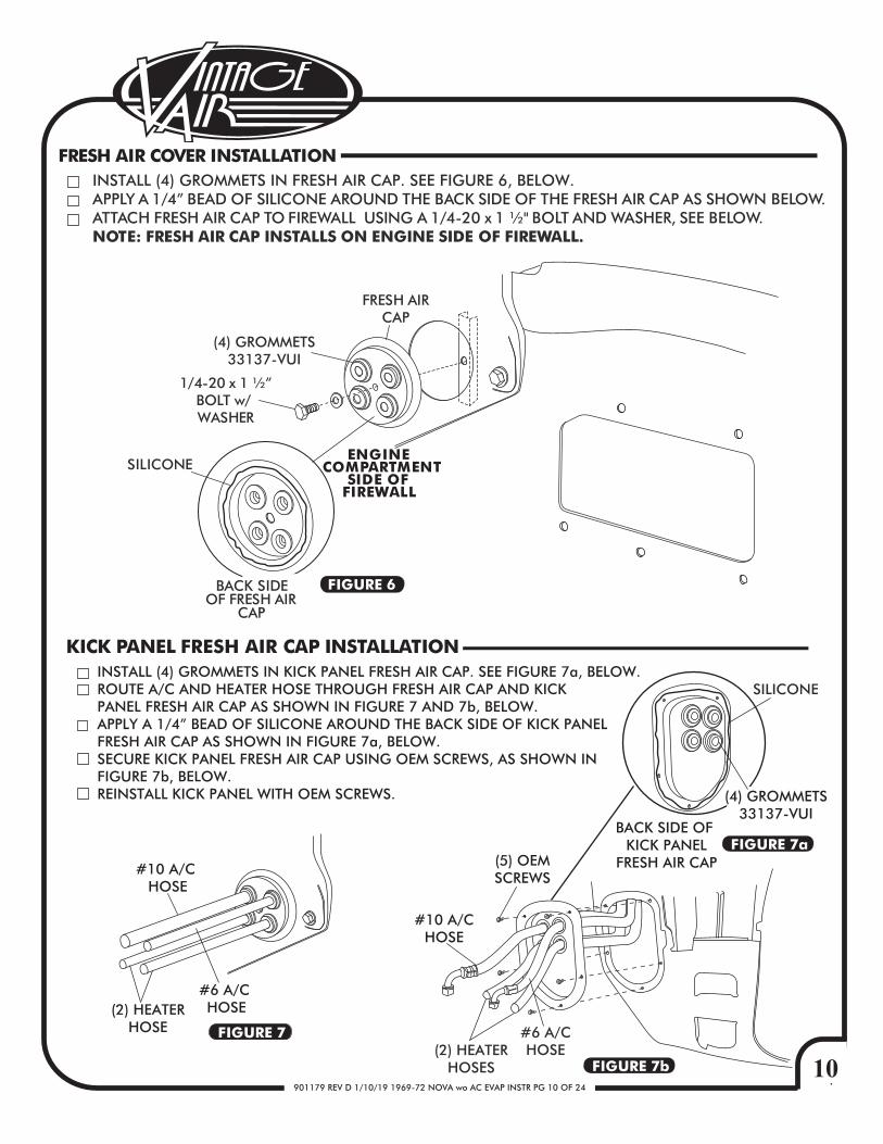
1/4-20 x 1 ½”BOLT w/ WASHER
FRESH AIR COVER INSTALLATION
SILICONE
FRESH AIRCAP
(4) GROMMETS33137-VUI
FIGURE 6BACK SIDEOF FRESH AIR
CAP
ENGINE COMPARTMENT
SIDE OF FIREWALL
INSTALL (4) GROMMETS IN FRESH AIR CAP. SEE FIGURE 6, BELOW.APPLY A 1/4” BEAD OF SILICONE AROUND THE BACK SIDE OF THE FRESH AIR CAP AS SHOWN BELOW.ATTACH FRESH AIR CAP TO FIREWALL USING A 1/4-20 x 1 ½" BOLT AND WASHER, SEE BELOW. NOTE: FRESH AIR CAP INSTALLS ON ENGINE SIDE OF FIREWALL.
FIGURE 7b
FIGURE 7a
FIGURE 7
KICK PANEL FRESH AIR CAP INSTALLATIONINSTALL (4) GROMMETS IN KICK PANEL FRESH AIR CAP. SEE FIGURE 7a, BELOW.ROUTE A/C AND HEATER HOSE THROUGH FRESH AIR CAP AND KICKPANEL FRESH AIR CAP AS SHOWN IN FIGURE 7 AND 7b, BELOW.APPLY A 1/4” BEAD OF SILICONE AROUND THE BACK SIDE OF KICK PANEL FRESH AIR CAP AS SHOWN IN FIGURE 7a, BELOW.SECURE KICK PANEL FRESH AIR CAP USING OEM SCREWS, AS SHOWN IN FIGURE 7b, BELOW.REINSTALL KICK PANEL WITH OEM SCREWS.
(5) OEMSCREWS
SILICONE
BACK SIDE OF KICK PANEL
FRESH AIR CAP
#10 A/CHOSE
#6 A/CHOSE(2) HEATER
HOSES
#10 A/C HOSE
#6 A/C HOSE(2) HEATER
HOSE
(4) GROMMETS33137-VUI
11901179 REV D 1/10/19 1969-72 NOVA wo AC EVAP INSTR PG 11 OF 24
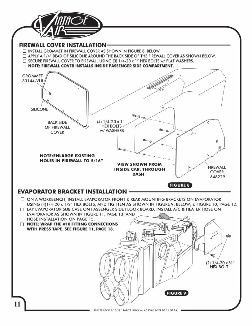
INSTALL GROMMET IN FIREWALL COVER AS SHOWN IN FIGURE 8, BELOW APPLY A 1/4“ BEAD OF SILICONE AROUND THE BACK SIDE OF THE FIREWALL COVER AS SHOWN BELOW.SECURE FIREWALL COVER TO FIREWALL USING (3) 1/4-20 x 1” HEX BOLTS w/ FLAT WASHERS. NOTE: FIREWALL COVER INSTALLS INSIDE PASSENGER SIDE COMPARTMENT.
FIREWALL COVER INSTALLATION
NOTE:ENLARGE EXISTING HOLES IN FIREWALL TO 5/16”
FIGURE 8
FIREWALLCOVER648229
VIEW SHOWN FROMINSIDE CAR, THROUGH
DASH
SILICONE
GROMMET33144-VUI
BACK SIDEOF FIREWALL
COVER
(4) 1/4-20 x 1”HEX BOLTS
w/ WASHERS
EVAPORATOR BRACKET INSTALLATION
(2) 1/4-20 x ½”HEX BOLT
FIGURE 9
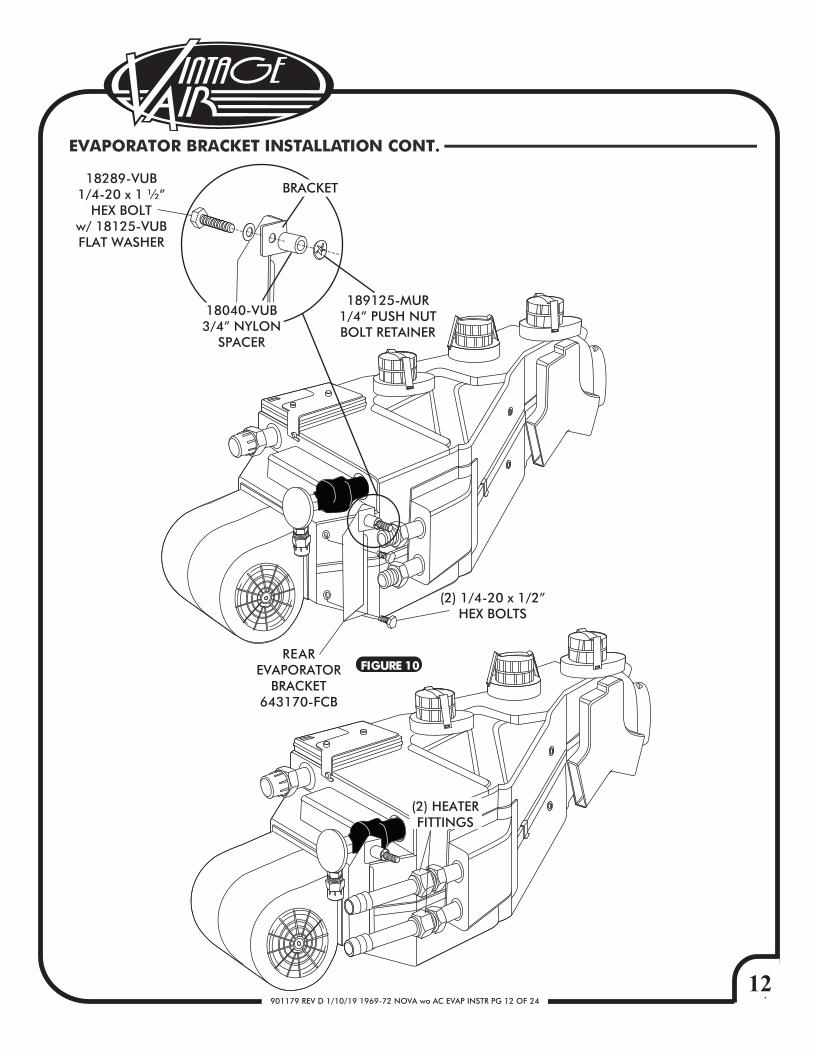
ON A WORKBENCH, INSTALL EVAPORATOR FRONT & REAR MOUNTING BRACKETS ON EVAPORATOR USING (4)1/4-20 x 1/2” HEX BOLTS, AND TIGHTEN AS SHOWN IN FIGURE 9, BELOW, & FIGURE 10, PAGE 12.LAY EVAPORATOR SUB CASE ON PASSENGER SIDE FLOOR BOARD. INSTALL A/C & HEATER HOSE ON EVAPORATOR AS SHOWN IN FIGURE 11, PAGE 13, AND HOSE INSTALLATION ON PAGE 15.NOTE: WRAP THE #10 FITTING CONNECTIONS WITH PRESS TAPE. SEE FIGURE 11, PAGE 13.
12901179 REV D 1/10/19 1969-72 NOVA wo AC EVAP INSTR PG 12 OF 24
REAREVAPORATOR
BRACKET643170-FCB
(2) 1/4-20 x 1/2”HEX BOLTS
(2) HEATERFITTINGS
EVAPORATOR BRACKET INSTALLATION CONT.
FIGURE 10
18040-VUB3/4” NYLON
SPACER
189125-MUR1/4” PUSH NUTBOLT RETAINER
BRACKET18289-VUB
1/4-20 x 1 ½”HEX BOLT
w/ 18125-VUBFLAT WASHER
13901179 REV D 1/10/19 1969-72 NOVA wo AC EVAP INSTR PG 13 OF 24
LIFT EVAPORATOR UNIT UP UNDER THE DASHBOARD. SECURE LOOSELY TO THE FIREWALL FROM THE ENGINE COMPARTMENT SIDE USING 1/4-20 NUT w/ STAR WASHER AND FLAT WASHER. SEE FIGURE 12 BELOW. NOTE: TO ENSURE PROPER DRAINAGE, IT IS VERY IMPORTANT THAT THE EVAPORATOR IS LEVEL, BOTH LEFT-RIGHT AND FORE-AFT. CHECK FOR LEVEL ON THE FLAT PORTIONS OF THE CASE AROUND THE DRAIN, BLOCK THE UNITUP, THEN DRILL FOR FRONT BRACKET SCREWS.USING (2) #14 x ¾ SHEET METAL SCREWS, SECURE THE FRONT EVAPORATOR MOUNTING BRACKET TO THE INNER COWL. SEE FIGURE 12a BELOW.VERIFY THAT EVAPORATOR UNIT IS LEVEL AND SQUARE TO THE DASH, THEN TIGHTEN ALL MOUNTING BOLTS.NOTE: TIGHTEN THE BOLT ON FIREWALL FIRST, THEN THE FRONT MOUNTING BRACKET SCREWS.
INNER COWL
DRILL (2)3/16” HOLES (2)#14 x ¾”
SHEET METALSCREWS
FIGURE 11
FIGURE 12
FIGURE 12a
EVAPORATOR INSTALLATION
#10 A/C HOSE
HOSECLAMPSHEATER
HOSE
#6 A/C HOSE
PRESSTAPE
1/4-20 NUTw/ STAR WASHERw/ FLAT WASHER
KICK PANELFRESH AIR
CAP
14901179 REV D 1/10/19 1969-72 NOVA wo AC EVAP INSTR PG 14 OF 24
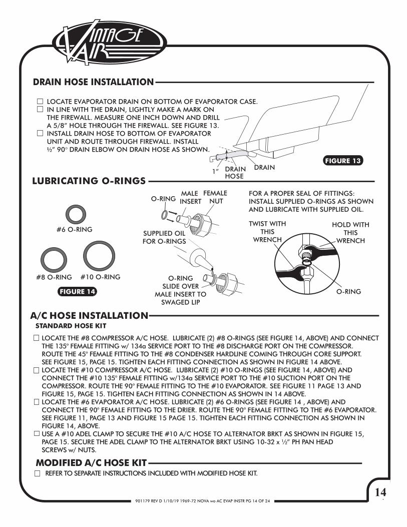
DRAIN HOSE INSTALLATION
FIGURE 13
O-RINGMALE INSERT
FEMALE NUT
SUPPLIED OILFOR O-RINGS
O-RINGSLIDE OVER
MALE INSERT TOSWAGED LIP
TWIST WITHTHIS
WRENCH
HOLD WITHTHIS
WRENCH
FOR A PROPER SEAL OF FITTINGS:INSTALL SUPPLIED O-RINGS AS SHOWNAND LUBRICATE WITH SUPPLIED OIL.
LOCATE EVAPORATOR DRAIN ON BOTTOM OF EVAPORATOR CASE.IN LINE WITH THE DRAIN, LIGHTLY MAKE A MARK ONTHE FIREWALL. MEASURE ONE INCH DOWN AND DRILLA 5/8” HOLE THROUGH THE FIREWALL. SEE FIGURE 13.INSTALL DRAIN HOSE TO BOTTOM OF EVAPORATORUNIT AND ROUTE THROUGH FIREWALL. INSTALL½” 90° DRAIN ELBOW ON DRAIN HOSE AS SHOWN.
O-RING
#6 O-RING
#8 O-RING #10 O-RING
FIGURE 14
LUBRICATING O-RINGS
DRAINDRAINHOSE
1”
LOCATE THE #8 COMPRESSOR A/C HOSE. LUBRICATE (2) #8 O-RINGS (SEE FIGURE 14, ABOVE) AND CONNECTTHE 135° FEMALE FITTING w/ 134a SERVICE PORT TO THE #8 DISCHARGE PORT ON THE COMPRESSOR.ROUTE THE 45° FEMALE FITTING TO THE #8 CONDENSER HARDLINE COMING THROUGH CORE SUPPORT. SEE FIGURE 15, PAGE 15. TIGHTEN EACH FITTING CONNECTION AS SHOWN IN FIGURE 14 ABOVE.LOCATE THE #10 COMPRESSOR A/C HOSE. LUBRICATE (2) #10 O-RINGS (SEE FIGURE 14, ABOVE) ANDCONNECT THE #10 135° FEMALE FITTING w/134a SERVICE PORT TO THE #10 SUCTION PORT ON THECOMPRESSOR. ROUTE THE 90° FEMALE FITTING TO THE #10 EVAPORATOR. SEE FIGURE 11 PAGE 13 ANDFIGURE 15, PAGE 15. TIGHTEN EACH FITTING CONNECTION AS SHOWN IN 14 ABOVE. LOCATE THE #6 EVAPORATOR A/C HOSE. LUBRICATE (2) #6 O-RINGS (SEE FIGURE 14 , ABOVE) ANDCONNECT THE 90° FEMALE FITTING TO THE DRIER. ROUTE THE 90° FEMALE FITTING TO THE #6 EVAPORATOR. SEE FIGURE 11, PAGE 13 AND FIGURE 15 PAGE 15. TIGHTEN EACH FITTING CONNECTION AS SHOWN IN FIGURE 14, ABOVE.USE A #10 ADEL CLAMP TO SECURE THE #10 A/C HOSE TO ALTERNATOR BRKT AS SHOWN IN FIGURE 15, PAGE 15. SECURE THE ADEL CLAMP TO THE ALTERNATOR BRKT USING 10-32 x ½” PH PAN HEAD SCREWS w/ NUTS.
A/C HOSE INSTALLATIONSTANDARD HOSE KIT
REFER TO SEPARATE INSTRUCTIONS INCLUDED WITH MODIFIED HOSE KIT. MODIFIED A/C HOSE KIT
15901179 REV D 1/10/19 1969-72 NOVA wo AC EVAP INSTR PG 15 OF 24
NO
TE:
VIN
TAG
E A
IR S
YSTE
MS
REQ
UIR
E(2
) 5
/8”
HO
SE N
IPPL
ES (
NO
T SU
PPLI
ED)
CO
MPR
ESSO
RSA
FETY
SW
ITC
H(B
INA
RY T
YPE)
SCRE
W O
N D
RIER
(REF
ER T
OC
ON
DEN
SER
INST
RUC
TIO
NS)
#8 C
ON
DEN
SER/
CO
MP
HA
RDLI
NE
091165
#8
CO
ND
ENSE
R/H
ARD
LIN
E0
9169-F
FD#
6 H
ARD
LIN
ED
RIER
/ C
ON
DEN
SER
09
11
64
#6
A/C
HO
SE0
96
06
6
A/C
& H
EATE
R H
OSE
RO
UTI
NG
FIG
UR
E 1
5
#1
0 A
DEL
CLA
MP
w/
10
-32
x 1
/2”
PAN
H
EAD
SC
REW
w/
NU
TTI
E W
RAP
R
#1
0 S
UC
TIO
NH
OSE
09
60
73
#8
DIS
CH
ARG
EH
OSE
09
01
67
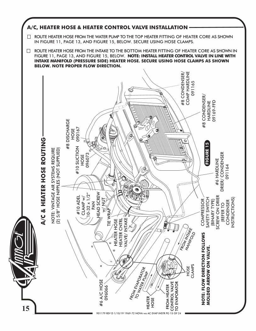
A/C, HEATER HOSE & HEATER CONTROL VALVE INSTALLATION
ROUTE HEATER HOSE FROM THE WATER PUMP TO THE TOP HEATER FITTING OF HEATER CORE AS SHOWN IN FIGURE 11, PAGE 13, AND FIGURE 15, BELOW. SECURE USING HOSE CLAMPS.
ROUTE HEATER HOSE FROM THE INTAKE TO THE BOTTOM HEATER FITTING OF HEATER CORE AS SHOWN IN FIGURE 11, PAGE 13, AND FIGURE 15, BELOW. NOTE: INSTALL HEATER CONTROL VALVE IN LINE WITH INTAKE MANIFOLD (PRESSURE SIDE) HEATER HOSE. SECURE USING HOSE CLAMPS AS SHOWN BELOW. NOTE PROPER FLOW DIRECTION.
HEA
TER
HO
SEH
EATE
R C
NTR
LV
ALV
E/ IN
TAK
E
FRO
M IN
TAKE
MAN
IFO
LD
FRO
M E
VAPO
RATO
R
TO W
ATER
PU
MP HO
SEC
LAM
PS
FRO
M H
EATE
R C
ON
TRO
L VA
LVE
TO E
VA
PORA
TOR
HEA
TER
HO
SE
NO
TE:
FLO
W D
IREC
TIO
N F
OLL
OW
S M
OLD
ED A
RR
OW
ON
VA
LVE.
16901179 REV D 1/10/19 1969-72 NOVA wo AC EVAP INSTR PG 16 OF 24
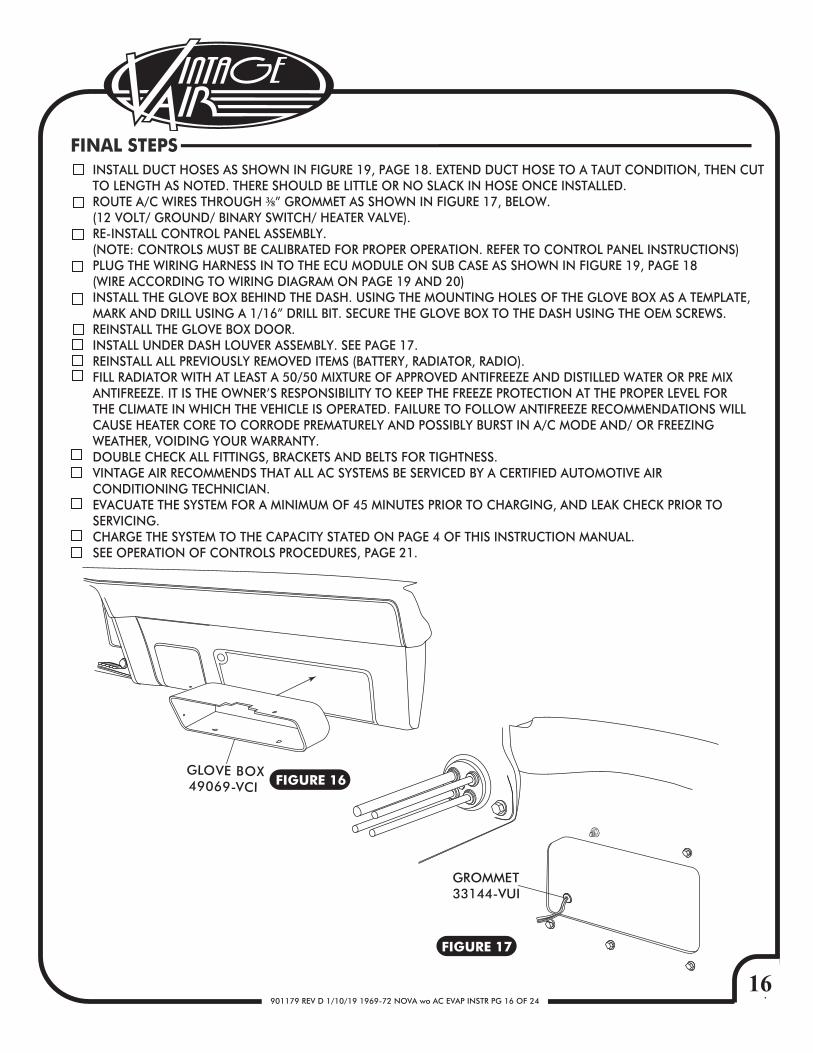
INSTALL DUCT HOSES AS SHOWN IN FIGURE 19, PAGE 18. EXTEND DUCT HOSE TO A TAUT CONDITION, THEN CUTTO LENGTH AS NOTED. THERE SHOULD BE LITTLE OR NO SLACK IN HOSE ONCE INSTALLED.ROUTE A/C WIRES THROUGH ⅜” GROMMET AS SHOWN IN FIGURE 17, BELOW.(12 VOLT/ GROUND/ BINARY SWITCH/ HEATER VALVE).RE-INSTALL CONTROL PANEL ASSEMBLY.(NOTE: CONTROLS MUST BE CALIBRATED FOR PROPER OPERATION. REFER TO CONTROL PANEL INSTRUCTIONS)PLUG THE WIRING HARNESS IN TO THE ECU MODULE ON SUB CASE AS SHOWN IN FIGURE 19, PAGE 18(WIRE ACCORDING TO WIRING DIAGRAM ON PAGE 19 AND 20)INSTALL THE GLOVE BOX BEHIND THE DASH. USING THE MOUNTING HOLES OF THE GLOVE BOX AS A TEMPLATE,MARK AND DRILL USING A 1/16” DRILL BIT. SECURE THE GLOVE BOX TO THE DASH USING THE OEM SCREWS.REINSTALL THE GLOVE BOX DOOR.INSTALL UNDER DASH LOUVER ASSEMBLY. SEE PAGE 17.REINSTALL ALL PREVIOUSLY REMOVED ITEMS (BATTERY, RADIATOR, RADIO).FILL RADIATOR WITH AT LEAST A 50/50 MIXTURE OF APPROVED ANTIFREEZE AND DISTILLED WATER OR PRE MIX ANTIFREEZE. IT IS THE OWNER’S RESPONSIBILITY TO KEEP THE FREEZE PROTECTION AT THE PROPER LEVEL FOR THE CLIMATE IN WHICH THE VEHICLE IS OPERATED. FAILURE TO FOLLOW ANTIFREEZE RECOMMENDATIONS WILL CAUSE HEATER CORE TO CORRODE PREMATURELY AND POSSIBLY BURST IN A/C MODE AND/ OR FREEZING WEATHER, VOIDING YOUR WARRANTY.DOUBLE CHECK ALL FITTINGS, BRACKETS AND BELTS FOR TIGHTNESS.VINTAGE AIR RECOMMENDS THAT ALL AC SYSTEMS BE SERVICED BY A CERTIFIED AUTOMOTIVE AIR CONDITIONING TECHNICIAN.EVACUATE THE SYSTEM FOR A MINIMUM OF 45 MINUTES PRIOR TO CHARGING, AND LEAK CHECK PRIOR TO SERVICING.CHARGE THE SYSTEM TO THE CAPACITY STATED ON PAGE 4 OF THIS INSTRUCTION MANUAL.SEE OPERATION OF CONTROLS PROCEDURES, PAGE 21.
FINAL STEPS
FIGURE 16
FIGURE 17
GROMMET33144-VUI
GLOVE BOX49069-VCI
17901179 REV D 1/10/19 1969-72 NOVA wo AC EVAP INSTR PG 17 OF 24
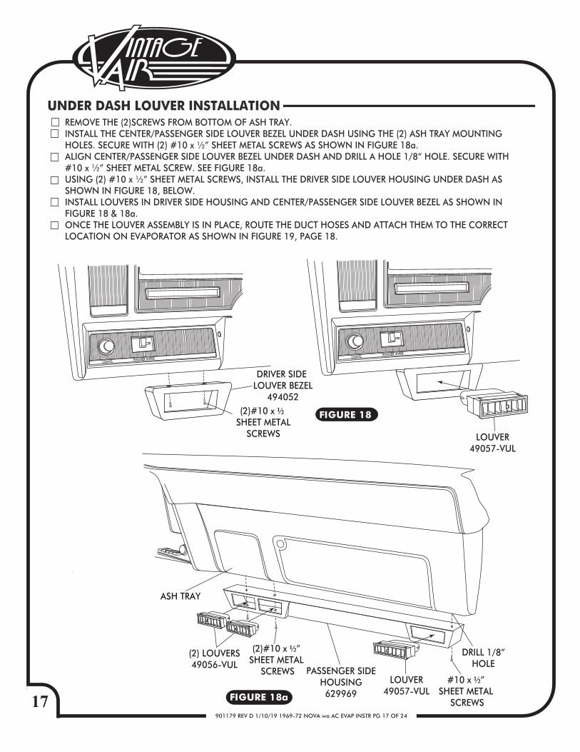
PASSENGER SIDEHOUSING629969
DRILL 1/8”HOLE
(2) LOUVERS49056-VUL
FIGURE 18a
FIGURE 18
(2)#10 x ½” SHEET METAL
SCREWS
ASH TRAY
(2)#10 x ½ SHEET METAL
SCREWS
DRIVER SIDE LOUVER BEZEL
494052
LOUVER49057-VUL
LOUVER49057-VUL
REMOVE THE (2)SCREWS FROM BOTTOM OF ASH TRAY.INSTALL THE CENTER/PASSENGER SIDE LOUVER BEZEL UNDER DASH USING THE (2) ASH TRAY MOUNTINGHOLES. SECURE WITH (2) #10 x ½” SHEET METAL SCREWS AS SHOWN IN FIGURE 18a.ALIGN CENTER/PASSENGER SIDE LOUVER BEZEL UNDER DASH AND DRILL A HOLE 1/8“ HOLE. SECURE WITH #10 x ½” SHEET METAL SCREW. SEE FIGURE 18a.USING (2) #10 x ½” SHEET METAL SCREWS, INSTALL THE DRIVER SIDE LOUVER HOUSING UNDER DASH AS SHOWN IN FIGURE 18, BELOW.INSTALL LOUVERS IN DRIVER SIDE HOUSING AND CENTER/PASSENGER SIDE LOUVER BEZEL AS SHOWN INFIGURE 18 & 18a.ONCE THE LOUVER ASSEMBLY IS IN PLACE, ROUTE THE DUCT HOSES AND ATTACH THEM TO THE CORRECT LOCATION ON EVAPORATOR AS SHOWN IN FIGURE 19, PAGE 18.
UNDER DASH LOUVER INSTALLATION
LIGHTS WASHER WIPER LIGHTS WASHER WIPER
#10 x ½” SHEET METAL
SCREWS
18901179 REV D 1/10/19 1969-72 NOVA wo AC EVAP INSTR PG 18 OF 24
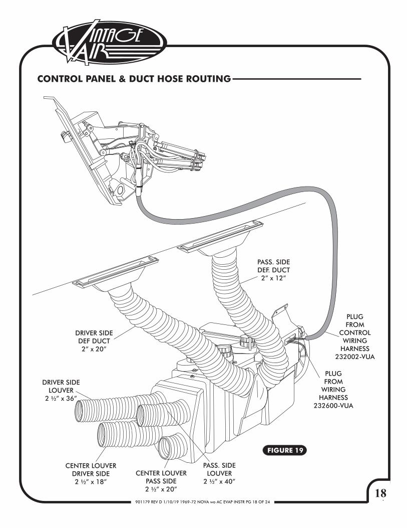
FIGURE 19
CONTROL PANEL & DUCT HOSE ROUTING
PLUGFROM
CONTROLWIRING
HARNESS232002-VUA
PLUGFROM
WIRINGHARNESS
232600-VUA
PASS. SIDELOUVER
2 ½” x 40”
DRIVER SIDELOUVER
2 ½” x 36”
CENTER LOUVERDRIVER SIDE2 ½” x 18”
CENTER LOUVERPASS SIDE2 ½” x 20”
PASS. SIDEDEF. DUCT2” x 12”
DRIVER SIDEDEF DUCT2” x 20”
19901179 REV D 1/10/19 1969-72 NOVA wo AC EVAP INSTR PG 19 OF 24
WHT/GRN
WHT/YELWHT/RED
RED
WHTBACKLIGHT NEG
FAN WIPER
MODE WIPER
TEMP WIPER
5V-SW
GND
BACKLIGHT POS
AC ANNUNCIATOR
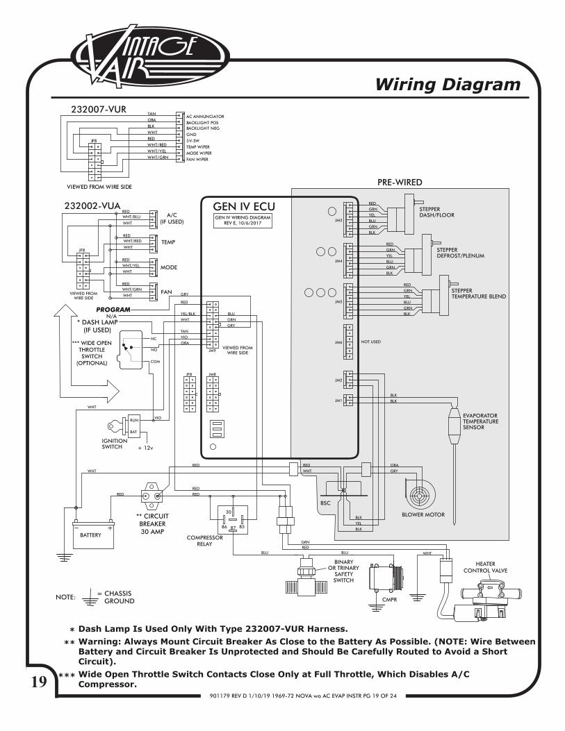
PRE-WIRED
GEN IV WIRING DIAGRAMREV E, 10/6/2017
GEN IV ECU
PROGRAM
Wiring Diagram
TEMP
MODE
FAN
A/C(IF USED)
232007-VUR
232002-VUA
** CIRCUITBREAKER30 AMP
*** WIDE OPENTHROTTLESWITCH
(OPTIONAL)
* DASH LAMP(IF USED)
Dash Lamp Is Used Only With Type 232007-VUR Harness.Warning: Always Mount Circuit Breaker As Close to the Battery As Possible. (NOTE: Wire BetweenBattery and Circuit Breaker Is Unprotected and Should Be Carefully Routed to Avoid a ShortCircuit).Wide Open Throttle Switch Contacts Close Only at Full Throttle, Which Disables A/C Compressor.
JF8
BLK
ORA
TAN
VIEWED FROM WIRE SIDE
* **
***
HEATERCONTROL VALVE
20901179 REV D 1/10/19 1969-72 NOVA wo AC EVAP INSTR PG 20 OF 24
RED
CIRCUIT BREAKER30 AMP
+
+
-
BLACK
REDWHITE
RED
CHASSIS GROUND
A/CCOMPRESSOR
RELAY
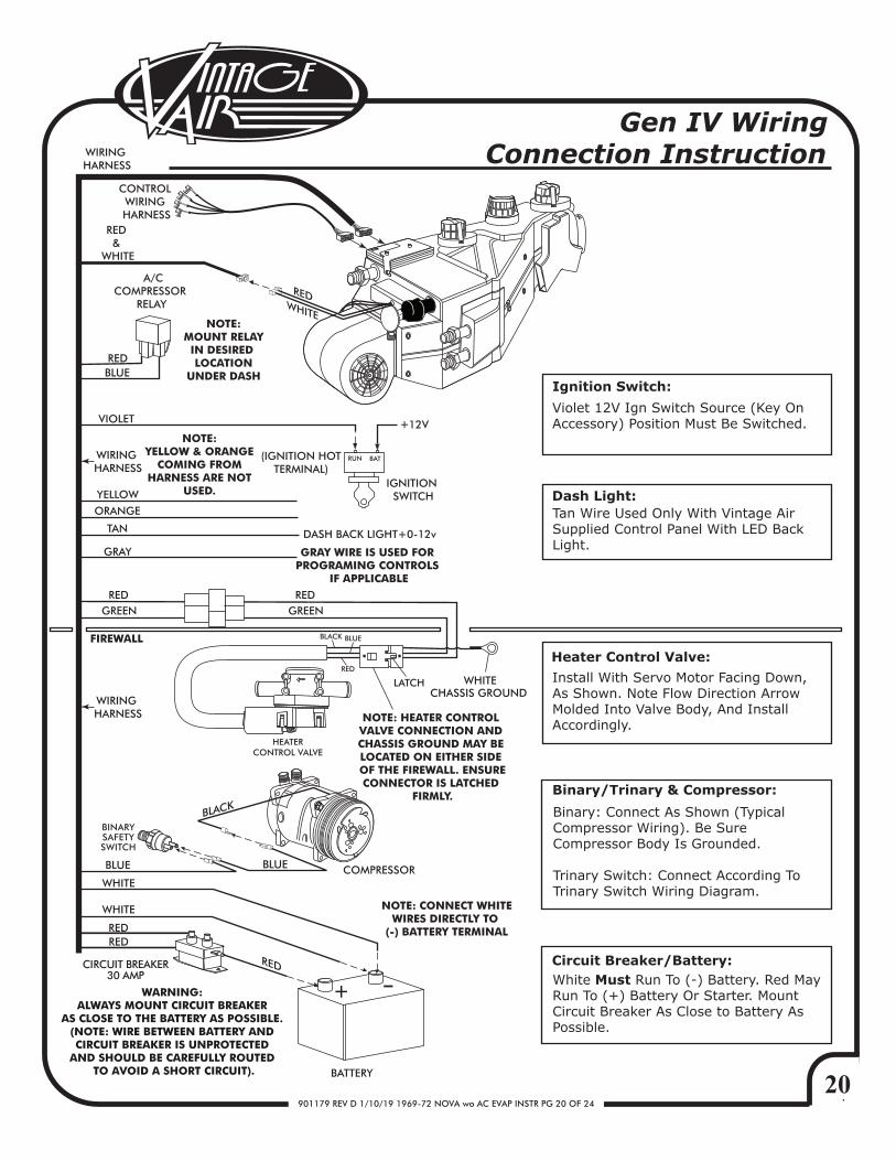
Ignition Switch:
Dash Light:
NOTE: MOUNT RELAYIN DESIRED LOCATION
UNDER DASH
GREEN
FIREWALL
BLUE
BLUE
RED &
WHITE
VIOLET
(IGNITION HOTTERMINAL)
IGNITION SWITCH
DASH BACK LIGHT+0-12vTAN
GRAY
BLUE
WHITE
WHITE
REDRED
WHITE
COMPRESSOR
BATTERY
NOTE: CONNECT WHITEWIRES DIRECTLY TO
(-) BATTERY TERMINAL
BATRUN
12V
RED GREEN
RED
RED
BLUE
LATCH
BLACK
BINARYSAFETYSWITCH
YELLOW
ORANGE
WIRING HARNESS
Violet 12V Ign Switch Source (Key On Accessory) Position Must Be Switched.
Tan Wire Used Only With Vintage Air Supplied Control Panel With LED Back Light.
Binary: Connect As Shown (Typical Compressor Wiring). Be Sure Compressor Body Is Grounded.
Trinary Switch: Connect According To Trinary Switch Wiring Diagram.
Install With Servo Motor Facing Down, As Shown. Note Flow Direction Arrow Molded Into Valve Body, And Install Accordingly.
White Must Run To (-) Battery. Red May Run To (+) Battery Or Starter. Mount Circuit Breaker As Close to Battery As Possible.
Heater Control Valve:
Binary/Trinary & Compressor:
Circuit Breaker/Battery:
CONTROL WIRING HARNESS
NOTE: YELLOW & ORANGE
COMING FROM HARNESS ARE NOT
USED.
WIRING HARNESS
GRAY WIRE IS USED FOR PROGRAMING CONTROLS
IF APPLICABLE
WIRING HARNESS
Gen IV Wiring Connection Instruction
HEATERCONTROL VALVE
WARNING: ALWAYS MOUNT CIRCUIT BREAKER
AS CLOSE TO THE BATTERY AS POSSIBLE. (NOTE: WIRE BETWEEN BATTERY AND CIRCUIT BREAKER IS UNPROTECTED
AND SHOULD BE CAREFULLY ROUTED TO AVOID A SHORT CIRCUIT).
NOTE: HEATER CONTROL VALVE CONNECTION AND CHASSIS GROUND MAY BE LOCATED ON EITHER SIDE OF THE FIREWALL. ENSURECONNECTOR IS LATCHED
FIRMLY.
21901179 REV D 1/10/19 1969-72 NOVA wo AC EVAP INSTR PG 21 OF 24
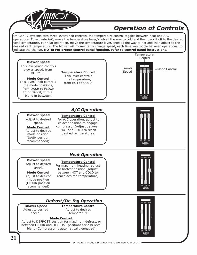
Operation of Controls
Adjust to desiredspeed.
Blower SpeedAdjust to desired
speed.
Adjust to desiredmode position (DASH position recommended).
Adjust to desiredspeed.
Adjust to DEFROST position for maximum defrost, or between FLOOR and DEFROST positions for a bi-level
blend (Compressor is automatically engaged).
Adjust to desired temperature.
For A/C operation, adjust tocoldest position to engage
compressor (Adjust between HOT and COLD to reachdesired temperature).
A/C Operation
Heat Operation
Defrost/De-fog Operation
Blower Speed
Blower Speed
This lever/knob controlsblower speed, from
OFF to HI.
This lever/knob controls the mode positions,from DASH to FLOORto DEFROST, with a blend in between.
This lever controlsthe temperature,
from HOT to COLD.
Blower Speed
Mode Control
Temperature ControlBlower Speed
Temperature Control
Mode Control
Temperature Control
Temperature Control
Temperature Control
Mode Control
Mode Control
Mode Control
For maximum heating, adjust to hottest position (Adjust between HOT and COLD to reach desired temperature).Adjust to desired
mode position(FLOOR position recommended).
On Gen IV systems with three lever/knob controls, the temperature control toggles between heat and A/C operations. To activate A/C, move the temperature lever/knob all the way to cold and then back it off to the desired vent temperature. For heat operation, move the temperature lever/knob all the way to hot and then adjust to the desired vent temperature. The blower will momentarily change speed, each time you toggle between operations, to indicate the change. NOTE: For proper control panel function, refer to control panel instructions.
COLD
HOT
HI
OFF
DASH
DEF
FLR
COLD
HOT
HI
OFF
DASH
DEF
FLR
HOTOFF
DASH
DEF
FLR
COLDHI
HOTOFF
DASH
DEF
FLR
COLDHI
22901179 REV D 1/10/19 1969-72 NOVA wo AC EVAP INSTR PG 22 OF 24
Sym
pto
m
C
on
dit
ion
C
heck
s
Act
ion
s
N
ote
s
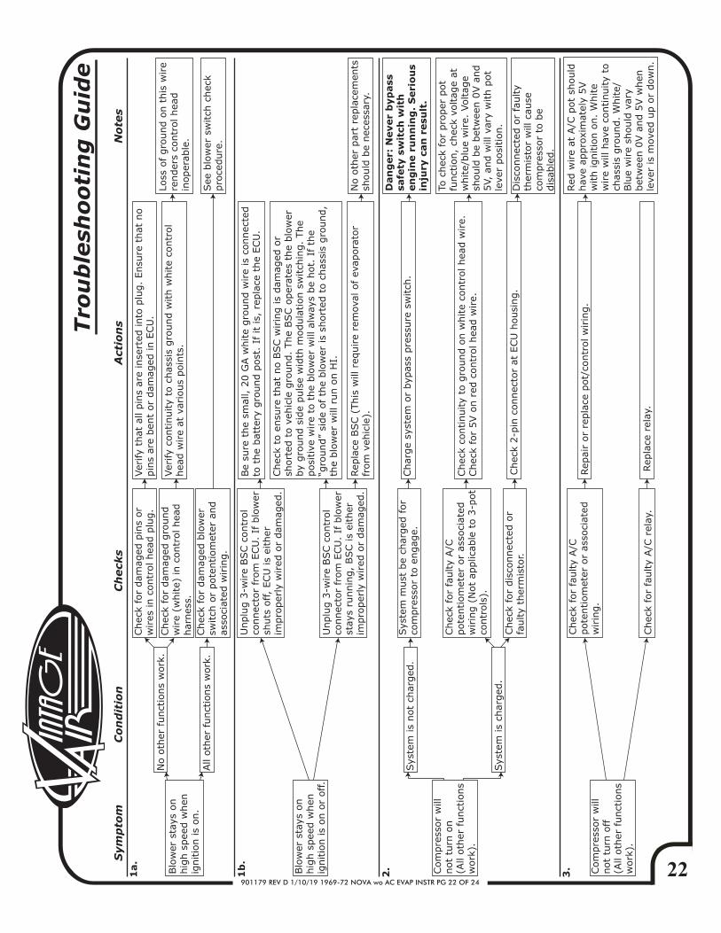
Blo
wer
sta
ys o
n
hig
h s
pee
d w
hen
ig
nitio
n is
on.
1a.
No o
ther
funct
ions
work
.
Chec
k fo
r dam
aged
pin
s or
wires
in c
ontr
ol hea
d p
lug.
Ver
ify
that
all
pin
s ar
e in
sert
ed into
plu
g.
Ensu
re t
hat
no
pin
s ar
e ben
t or
dam
aged
in E
CU
.
Chec
k fo
r dam
aged
gro
und
wire
(white)
in c
ontr
ol hea
d
har
nes
s.
Ver
ify
continuity
to c
has
sis
gro
und w
ith w
hite
contr
ol
hea
d w
ire
at v
ario
us
poin
ts.
Loss
of gro
und o
n t
his
wire
render
s co
ntr
ol hea
d
inoper
able
.
All
oth
er f
unct
ions
work
.Chec
k fo
r dam
aged
blo
wer
sw
itch
or
pote
ntiom
eter
and
asso
ciat
ed w
irin
g.
Blo
wer
sta
ys o
n
hig
h s
pee
d w
hen
ig
nitio
n is
on o
r off.
Unplu
g 3
-wire
BSC c
ontr
ol
connec
tor
from
ECU
. If
blo
wer
sh
uts
off,
ECU
is
eith
er
impro
per
ly w
ired
or
dam
aged
.
Be
sure
the
smal
l, 2
0 G
A w
hite
gro
und w
ire
is c
onnec
ted
to t
he
bat
tery
gro
und p
ost
. If
it
is,
repla
ce t
he
ECU
.
Unplu
g 3
-wire
BSC c
ontr
ol
connec
tor
from
ECU
. If
blo
wer
st
ays
runnin
g,
BSC is
eith
er
impro
per
ly w
ired
or
dam
aged
.
Chec
k to
ensu
re t
hat
no B
SC w
irin
g is
dam
aged
or
short
ed t
o v
ehic
le g
round.
The
BSC o
per
ates
the
blo
wer
by
gro
und s
ide
puls
e w
idth
modula
tion s
witch
ing.
The
posi
tive
wire
to t
he
blo
wer
will
alw
ays
be
hot.
If th
e “g
round”
side
of
the
blo
wer
is
short
ed t
o c
has
sis
gro
und,
the
blo
wer
will
run o
n H
I.
Rep
lace
BSC (
This
will
req
uire
rem
oval
of ev
apora
tor
from
veh
icle
).N
o o
ther
par
t re
pla
cem
ents
sh
ould
be
nec
essa
ry.
Com
pre
ssor
will
not
turn
on
(All
oth
er funct
ions
work
).
2.
Sys
tem
is
not
char
ged
.Sys
tem
must
be
char
ged
for
com
pre
ssor
to e
ngag
e.Char
ge
syst
em o
r byp
ass
pre
ssure
sw
itch
.
Dan
ger:
Never
byp
ass
sa
fety
sw
itch
wit
h
en
gin
e r
un
nin
g.
Seri
ou
s in
jury
can
resu
lt.
Sys
tem
is
char
ged
.
1b
.
Tro
ub
lesh
oo
tin
g G
uid
e
Chec
k fo
r fa
ulty
A/C
pote
ntiom
eter
or
asso
ciat
ed
wirin
g (
Not
applic
able
to 3
-pot
contr
ols
).
Chec
k fo
r dis
connec
ted o
r fa
ulty
ther
mis
tor.
Chec
k co
ntinuity
to g
round o
n w
hite
contr
ol hea
d w
ire.
Chec
k fo
r 5V o
n r
ed c
ontr
ol hea
d w
ire.
Chec
k 2-p
in c
onnec
tor
at E
CU
housi
ng.
To c
hec
k fo
r pro
per
pot
funct
ion,
chec
k vo
ltag
e at
w
hite/
blu
e w
ire.
Voltag
e sh
ould
be
bet
wee
n 0
V a
nd
5V,
and w
ill v
ary
with p
ot
leve
r posi
tion.
Dis
connec
ted o
r fa
ulty
ther
mis
tor
will
cau
se
com
pre
ssor
to b
e dis
able
d.
Red
wire
at A
/C p
ot
should
hav
e ap
pro
xim
atel
y 5V
with ignitio
n o
n.
White
wire
will
hav
e co
ntinuity
to
chas
sis
gro
und.
White/
Blu
e w
ire
should
var
y bet
wee
n 0
V a
nd 5
V w
hen
le
ver
is m
oved
up o
r dow
n.
3. Com
pre
ssor
will
not
turn
off
(A
ll oth
er funct
ions
work
).
Chec
k fo
r fa
ulty
A/C
pote
ntiom
eter
or
asso
ciat
ed
wirin
g.
Chec
k fo
r fa
ulty
A/C
rel
ay.
Rep
air
or
repla
ce p
ot/
contr
ol w
irin
g.
Rep
lace
rel
ay.
See
blo
wer
sw
itch
chec
k pro
cedure
.
23901179 REV D 1/10/19 1969-72 NOVA wo AC EVAP INSTR PG 23 OF 24
Sym
pto
m
C
on
dit
ion
C
heck
s
Act
ion
s
N
ote
s
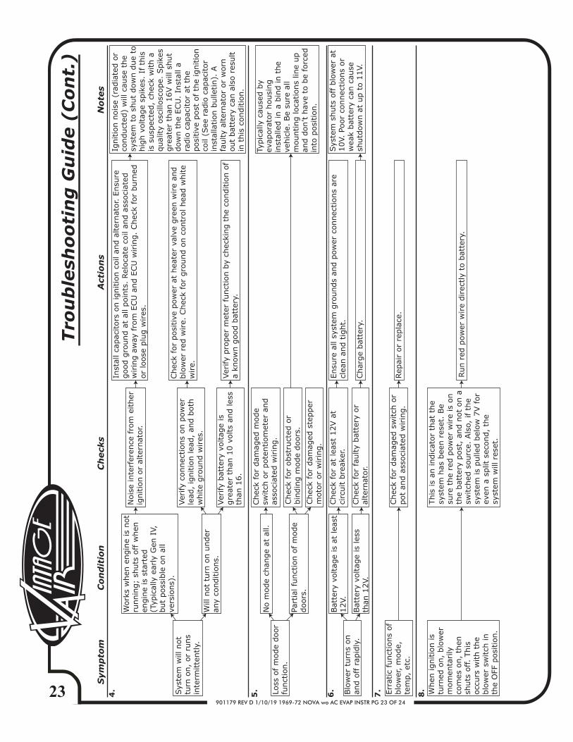
Sys
tem
will
not
turn
on,
or
runs
inte
rmitte
ntly.
4.
Work
s w
hen
engin
e is
not
runnin
g;
shuts
off w
hen
en
gin
e is
sta
rted
(T
ypic
ally
ear
ly G
en I
V,
but
poss
ible
on a
ll ve
rsio
ns)
.
Nois
e in
terf
eren
ce f
rom
either
ig
nitio
n o
r al
tern
ator.
Inst
all ca
pac
itors
on ignitio
n c
oil
and a
lter
nat
or. E
nsu
re
good g
round a
t al
l poin
ts.
Rel
oca
te c
oil
and a
ssoci
ated
w
irin
g a
way
fro
m E
CU
and E
CU
wirin
g.
Chec
k fo
r burn
edor
loose
plu
g w
ires
.
Ver
ify
connec
tions
on p
ow
er
lead
, ig
nitio
n lea
d,
and b
oth
white
gro
und w
ires
.
Ver
ify
pro
per
met
er f
unct
ion b
y ch
ecki
ng t
he
conditio
n o
f a
know
n g
ood b
atte
ry.
Ignitio
n n
ois
e (r
adia
ted o
rco
nduct
ed)
will
cau
se t
he
syst
em t
o s
hut
dow
n d
ue
tohig
h v
oltag
e sp
ikes
. If
this
is s
usp
ecte
d,
chec
k w
ith a
qual
ity
osc
illosc
ope.
Spik
esgre
ater
than
16V w
ill s
hut
dow
n t
he
ECU
. In
stal
l a
radio
cap
acitor
at t
he
posi
tive
post
of th
e ig
nitio
nco
il (S
ee r
adio
cap
acitor
inst
alla
tion b
ulle
tin).
A
faulty
alte
rnat
or
or
worn
out
bat
tery
can
als
o r
esult
in t
his
conditio
n.
Will
not
turn
on u
nder
an
y co
nditio
ns.
Ver
ify
bat
tery
voltag
e is
gre
ater
than
10 v
olts
and les
sth
an 1
6.
Loss
of m
ode
door
funct
ion.
No m
ode
chan
ge
at a
ll.Chec
k fo
r dam
aged
mode
switch
or
pote
ntiom
eter
and
asso
ciat
ed w
irin
g.
Part
ial fu
nct
ion o
f m
ode
doors
.
Typic
ally
cau
sed b
y ev
apora
tor
housi
ng
inst
alle
d in a
bin
d in t
he
vehic
le.
Be
sure
all
mounting loca
tions
line
up
and d
on’t h
ave
to b
e fo
rced
in
to p
osi
tion.
Blo
wer
turn
s on
and o
ff r
apid
ly.
6.
Bat
tery
voltag
e is
at
leas
t 12V.
Chec
k fo
r at
lea
st 1
2V a
t ci
rcuit b
reak
er.
Ensu
re a
ll sy
stem
gro
unds
and p
ow
er c
onnec
tions
are
clea
n a
nd t
ight.
Bat
tery
voltag
e is
les
s th
an 1
2V.
5.
Tro
ub
lesh
oo
tin
g G
uid
e (
Co
nt.
)
Chec
k fo
r fa
ulty
bat
tery
or
alte
rnat
or.
Char
ge
bat
tery
.
Sys
tem
shuts
off b
low
er a
t 10V.
Poor
connec
tions
or
wea
k bat
tery
can
cau
se
shutd
ow
n a
t up t
o 1
1V.
7. When
ignitio
n is
turn
ed o
n,
blo
wer
m
om
enta
rily
co
mes
on,
then
sh
uts
off.
This
occ
urs
with t
he
blo
wer
sw
itch
in
the
OFF
posi
tion.
This
is
an indic
ator
that
the
syst
em h
as b
een r
eset
. Be
sure
the
red p
ow
er w
ire
is o
nth
e bat
tery
post
, an
d n
ot
on a
sw
itch
ed s
ourc
e. A
lso,
if
the
syst
em is
pulle
d b
elow
7V f
or
even
a s
plit
sec
ond,
the
syst
em w
ill r
eset
.
Run r
ed p
ow
er w
ire
direc
tly
to b
atte
ry.
Chec
k fo
r posi
tive
pow
er a
t hea
ter
valv
e gre
en w
ire
and
blo
wer
red
wire.
Chec
k fo
r gro
und o
n c
ontr
ol hea
d w
hite
wire.
Chec
k fo
r obst
ruct
ed o
r bin
din
g m
ode
doors
.
Chec
k fo
r dam
aged
ste
pper
m
oto
r or
wirin
g.
Err
atic
funct
ions
of
blo
wer
, m
ode,
te
mp,
etc.
Chec
k fo
r dam
aged
sw
itch
or
pot
and a
ssoci
ated
wirin
g.
Rep
air
or
repla
ce.
8.
901179 REV D 1/10/18 1969-72 NOVA wo AC EVAP INSTR PG 24 OF 24
EVAPORATOR KIT 561072
CHECK BY:PACKED BY:
DATE:
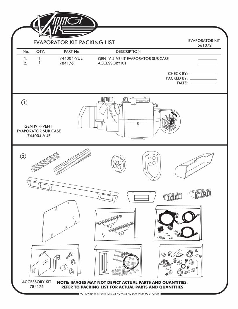
EVAPORATOR KIT PACKING LIST
No. QTY. PART No. DESCRIPTION
1.2.
11
744004-VUE784176
GEN IV 4-VENT EVAPORATOR SUB CASEACCESSORY KIT
GEN IV 4-VENT EVAPORATOR SUB CASE
744004-VUE
1
ACCESSORY KIT784176
NOTE: IMAGES MAY NOT DEPICT ACTUAL PARTS AND QUANTITIES.REFER TO PACKING LIST FOR ACTUAL PARTS AND QUANTITIES