ROTORBURST PROTECTIONPROGRAM: EXPERIMENTATION TO PROVIDE GUIDELINESFOR THE DESIGN OF TURBINE ROTOR BURST FRAGMENT CONTAINMENT RINGS* G. J. Mangano J. T. Salvlno R. A. DeLucla Naval Air Propulslon Test Center Princeton, New Jersey 08628 ABSTRACT ABSTRACT Presented are the results ofapro_am ofrotor burst containment experi- mentation that provides guldellnes for the design of optlmumwelght turblne rotor disk fragment containment rlngs. These guidelines were derived by estab- llshlng the relatlonshlps between a measure of the ring's capabillty to contain fragment energywith respect to it's weight (the specific contained fragment energy - SCFE - derived bydlvldlng the rotorburst energy by the weightof rlng required tocontain this energy) andother slgnlflcant rln8 and rotor t variables such as the: rotor tipdla_eter; number of rotor fragments; and ring radlal thickness and axial length. Theexperiments consi_'_d malnly of bursting 14 and 31 inch diameter turbine rotors into encirclinb containment rlngs made from centrifugally cast 4130 steel. Rules are given for achieving optlmumwelght rlng designs. _'-. *Prepared under NASA Defense Purchase Request C-41581-B, ._odification .. No. 6, for the NASA Lew_.s Research Center. Solomon Weiss, Robert D. Siewert, and Arthur G. Holms o5 the Levis Research Center served ea prosran uanasars and technical consultants for this program. Also published 88 NASA CR-135166, 1977. 107 https://ntrs.nasa.gov/search.jsp?R=19780002134 2018-09-20T12:02:24+00:00Z
Transcript
ROTORBURST PROTECTIONPROGRAM: EXPERIMENTATIONTO PROVIDE
GUIDELINES FOR THE DESIGN OF TURBINE ROTOR
BURST FRAGMENT CONTAINMENT RINGS*
G. J. Mangano
J. T. Salvlno
R. A. DeLucla
Naval Air Propulslon Test Center
Princeton, New Jersey 08628
ABSTRACT ABSTRACT
Presented are the results of a pro_am of rotor burst containment experi-
mentation that provides guldellnes for the design of optlmumwelght turblnerotor disk fragment containment rlngs. These guidelines were derived by estab-
llshlng the relatlonshlps between a measure of the ring's capabillty to containfragment energy with respect to it's weight (the specific contained fragment
energy - SCFE - derived by dlvldlng the rotor burst energy by the weight ofrlng required to contain this energy) and other slgnlflcant rln8 and rotor tvariables such as the: rotor tip dla_eter; number of rotor fragments; and
ring radlal thickness and axial length. The experiments consi_'_d malnly ofbursting 14 and 31 inch diameter turbine rotors into encirclinb containmentrlngs made from centrifugally cast 4130 steel. Rules are given for achieving
optlmumwelght rlng designs.
_'-. *Prepared under NASA Defense Purchase Request C-41581-B, ._odification.. No. 6, for the NASA Lew_.s Research Center. Solomon Weiss, Robert D. Siewert,
and Arthur G. Holms o5 the Levis Research Center served ea prosran uanasarsand technical consultants for this program. Also published 88 NASA CR-135166,1977.
The 9rogram of parametric rotor burst containment experimentationbeing reported was developed and conducted by the Naval Air PropulsionTest Center (NAPTC) under National Aeronautics and Space Administration_NASA) sponsorship. The program was structured to develop guideiines1or the design of optimum weight turbine rotor disk fragment contain-,_ent rings. The design guidelines were generated by experimentallyestablishing the relationship between a specific energy variable thatprovides a measure of ring containamnt capabiliw, and several selectvariables wi,ich characterize those configurationai aspects of thecontalnEent rings and rotor fragments that significantly influence thefragment containment process.
The program consisted of a series of rotor burst containmentexperiments in which rotors of two different diameters were modifiedto burst at their respective design speeds into various numbers (2,3 and 6) 9f pie-sector shaped fragments. These fragments impactedrings made from 4130 cast steel that encircled the rotors at a radialclearance of 0.5 inches (0.0127 m). The ring axial lengths werevaried in three discrete steps of 1/2, 1, and 2 times the rtr axiallength of the rotors used. The radial thicknesses of the rings werevaried until fragment containment was achieved, thus establishing theweight of rZng required. The results of test provided the guidelinesnecessary to design an optimum weight steel containment ring forsmall rotors. The optimum weight ring was 8.6 lbs (3.9 kg) for a14 inch (0.356 m) diameter rotor having a burst energy of 106 in-lbs(3511.6 J) at its deslgn speed of 20,000 rpm (2094 rad/s). This wetg_.tdecreased slightly with the numbex of fragments generated at burstin the range of from 2 to 6. The results also indicated that theweight of steel ring required to contain the pie-sector fragmentsfrom an average size conserclal engine turbine rotor (31 inch(0.787 m) diameter) having a burst energy of 10 g 106 in-lbs (. "16 J)would b__ in excess of 168 lbs (76.2 ks) for 2 and 3-fragment burstsand in the neighborhood of 150 lbs (68 kg) for a 6-fragment burst.Unlike the suall rotor containment ring characteristics, the weight
of ring required to contain these larger rotors was clearly dependenton the number of fragments generated at burst.
• -/ It was also found that a coiposite ring made from boron carbidebacked with filament wound fiberglass in an epoxy matrix containedthe fragments from the small rotor burst at a weight reduction of30% compared to steel. This represents • significant weight re-duction configuration that warrants further exploration.
: It would appear from the results of this effort that the steel"- rings required to contain the fragments generated by the burst of
an average size turbine rotor (the largnr of the two rotors tested)from a commercial engine would be heavy for aircraft appllcatlon.However, the use of optlmally configured composite rings for fragment
containment and partial rings for frapmnt deflection, which are systemschat show great promise for light-weight protection, should be thoroughlyinvestigated.
i 108
i "
1978002125-111
INTRODUCTION
This is a report on the Rotor Burst Protection Program (RBPP),which is sponsored by the National Aeronautics and Space Administration(NASA) and conducted by the Naval Air Propulsion Test Center (NAPTC).
The objective of this progrdm is to develop guidelines for the designof devices that will be used on aircraft to protect passengers and theaircraft structure from the lethal and devastating fragments that aregenerated by gas turbine engine rotor bursts.
Presented in this report are the results of a parametric testprogram that was conducted by the NAPTC to provide guidelines for thedesign of turbine rotor fragment containment rings. This program wasa sequel to, and to a large extend guided by, the exploratory testingthat was conducted by NAPTC and reported in reference (a).
CONCLUSIONS
I. Regarding tile containment of typical, relatively smll (14 inch(0.356 m)) diameter, axial flow turbine rotors that burst at their
design speeds into various numbers of pie-sector shaped fragmentshaving a total energy of approximately 106 in-lbs (3511.6 J):
a. Containment of these fragments can be achieved using rings: described as follows:
(1) Rings made from 6130 cast steel weighing 8.6 lbs (3.9 kg).!
b. Optimumweight for the steel containment ring configuration iwas achieved when the ring axial length was made equal to that of therotor; making the ring twice or half as long as the rotor axial lengthresulted in containment rings that were heavier and therefore lessthan optimmwtth respect to weight.
c. With the steel ring axial length at it's optimum value withrespect to weight, the ring thickness and therefore Its weight is,
/" for practical purposes, independent of the number (ranging from 2 to_ 6) of equal pie-sector shaped rotor fragments generated at burst.
2. Regarding the containment of typical relatively large (31 inchL_
(0.787 m)) axlal flow turbine rotors that burst at their designspeeds into various numbers of ple-sector shaped fragments havinga total energy of approximately 10 X 106 tn-lbs (35116 J):
_, 109
• .t s _ T '" '_ t ." t '
1978002125-112
a. Rings made from relatively brittle 4130 cast-steel weighingin excess of 168 Ibs (76.2 kg) will be required to contain 2 and 3
fragment rotor bursts. A ring of the same material weighing in theneighborhood of 150 Ibs (68 kg) will be required to contain a 6-
fragment burst.
b. The optimum weight of 4130 cast-steel ring required for con-
tainment is dependent on the number of ple-sector shaped fragments
generated at burst in the range of from 2 tO 6 fragments. The weightwill increase as the number of such fragments decreases.
RECOMMENDATIONS
I. Experimentation and analysis should be continued on a limited
basis to establish the baseline or reference steel ring weight
required to contain 2 and 3 fragment large rotor bursts.
2. Because the weight of steel rings required to contain the pie-sector shaped burst fragments from an average size comercial engineturbine rotor appears to be excessively high, the following twofacets of rotor burst protection should be further Investigated and ,°'
• design guidelines developed:
a. The use of multi-layered, multl-materlal rings for contain- '' merit applications, and
b. The use of partial rings to control the trajectories of rotorburst fragments (directing them away from the more vital areas ofthe aircraft Into the less or negligibly sensitive areas) as a means
• of providing a "degree" of protection at reduced weight.
PROGRANDESCRIPTION
A. Concept Development
•_ 1. The program of parametric turbine rotor fragment containmenttesting that is being reported was structured to develop empirical
•. j gnldellnes for the design of minimum weight turbine rotor d/sk.._ fragment containment rings made from a monolithic metal.
., The empirical design guidelines were generated by experimentallyestablishing the relationship between a variable that provides ameasure of containment ring capability and several other variablesthat both characterized the conflguratlonal aspects of the rotor
_ fragments and containment ring; and had been found from exploratory- testing to have had significant influence on the containment process.
110
1978002125-113
o.,
The variable that provided this measure of containment ringpotential or capability was termed the Specific Contained FragmentEnergy (SCFE) and was derived by dividing the rotor fragment energyat burst by the ring weight required to contain this energy. TheSCFE was the dependent variable of test.
2. The four ring and rotor characteristics that were chosen fortest because of their suspected influence on the containment process,and varied during test to establish what this influence was (as mea-sured by the SCFE) were as follows:
a. The ring inner diameter. Two diameters, one approximatelytwice as large as the other (31.64 and 15 inches) were used for testwith rotors having correspondingly larger and s_aller tip diameters(the CWJ65 and GEY58 engine turbine rotors having tip diameters of30.64 (.778 m) and 14 (0.356 m) inches, respectively). The burstenergies of these rotors at their nominal design speeds wereI0 X 106 and 106 in-lbs (35116 and 3511.6J) for the larger andsmaller rotor, respectively. Burst fragment energy (speed) was heldconstant from test to test as a function of rotor size; the largerrotor having the higher energy.
b. The rin& axial length. Three lengths were used thatcorresponded to 1/2, I end 2 times the rim axial lengths of thelarge and small rotors which were nominally 1.25 and 1 inch (.032and .0254 m), respectively.
c. The number of rotor fragments generated at burst. Therotors were modified to fail at their respective design speeds of8,500 rpm (890. tad/s) (J65 rotor) and 20,000 rpm (2094 tad/s) (T58rotor) and produce pie-sector shaped fragments having included anglesof 60" (1.0472 tad), 120" (2.0964 tad) and 180" (3.1416 tad). Thesewere termed 6, 3 end 2-fragment rotor bursts, respectively.
d. The ring radial thickness. The ring thickness was varieduntil fragment containment was achieved for the different combinationsof ring (rOtor) diameter; ring axial length; and number of rotorfragments.
/The resultant test matr/x for this test program is shown
in Figure I; and the procedure for rln8 thickness variation to._ achieve containment 18 shown sche_atlcally in Figure 2.
3. Other variables which wouId, in some way, influence themagnitude end orientation of the forces chat create the deformations
_, end displacements of the ring end rotor fragments, and thereforegovern the containment process are as foUows:
a. The mechanical properties of the rotor and ring mater/ale.
, ' 111
i
1978002125-114
'7_a,";
b. The fragment velocities.
c. The fragment masses and mass distributions.
d. The rotor-to-ring radial tip clearance.
e. The rotor tip-to-hub diameter or radius ratio.
Although these factors would significantly influence the contain-
ment process, with the exception of the ring material used forcontainment, the variability of these factors, as a function of rotor
size, are constrained within relatively narrow limits by the dictates
of rotor aerothermal and structural design. For all practical purposes
then, for a given rotor size, these factors would be essentially
invariate and the results generated by the experiments conducted would
be generally applicable to all turbines as a function of rotor size.
This would be so because the experimental scheme presented incorporates,
either purposely through the variables of test or inherently becauseactual rotors are used, all of the factors that could (with the
exception of ring material properties) significantly influence the
rotor fragment containment process.
Although the mechanical properties of the materials used to make
a containment ring can vary widely and are considered to be importantfactors in containment ring design, the ring material used in mostof the tests conducted was the same from one test to another. The
. material was 4130 cast steel. This was done to generate a baselinefor materials comparison in subsequent tests, and to establish theeffects of the other variables on the containment process exclusiveof material influences. Later when these effects are firmlyestabll_'_ed, the influence of ring materials will be more fullyexplo=_d. In fact, during the tests conducted the use of compositerings as containment devices were cursorily investigated.
B. Desigu Guidelines Synthesi=
/ 1. The conceptual functional relationship between the dependent/ (SCFE) and independent (t, ALR, NF, ID) variables of test are
: / presented cunceptually in Figure 3. Once these relationships areestablt, h,_d through test,they provide all the information that isneeded to design an optimum weight steel ring £or a turbine rotorfr_cent containment application. Given these relationships, thepzocedure would be as follows:
a. Three basic things would have to be known about therotor to proceed with the design analysis:
(1) The kinetic energy (KER) of the rotor at burst
(2) The rotor tip diameter, and
112
1978002125-115
(3) The rotor rim axial length.
These are characteristics that are usually known or can beeasily calculated by a designer.
b. The relationships between the SCFE, the number of frag-ments and rotor diameter, with the ratio of ring to rotor rim axiallength as the parameter, provide an indication of the worst tcombiv.,tion of burst conditions for the size rotor beingconsidered; i.e., the lowest SCFEo For a given analysis, this valueof SCFE would be obtained from the curves in Figure 3 (or equationsderived from regression analyses of the data points developed throughtest) for the size rotor being considered; the number of rotor
_ fragments that result in producing the most adverse containmentcondition with respect to weight of ring (the lowest SCFE value inthe SCFE-NF plane; and the optimum ring to rotor rim axial lengthratio (LRG/LRT -= ALR)), which is represented by the highest contourline. The SCFE value that is obtained by this exercise is divided
" into the total antic_.pated energy of the rotor to yield theoptimum (lowest) weight steel ring that will be required to containthe fragments. This procedure is expressed in equation (i).
?
(I) Wt = _KERSCFE
i ,- The weight so derived is then used in the following equation (2) _ b
which expresses the thickness of ring required for containment as afunction of all the other known dimensional variables.
lOf course the value of weight derived in equation (1) can be sub- I"stituted in equation (2) to yield perhaps a more useful form;
T
equation (Ta)
[ ]'(2a) t = RI2 + I{_l - RI
o,L'G
t = ring radial thickness required for containsent
: Ri - ring inner radius, which, for practical considerations,-" equals the rotor tip radius because rotor-to-e_in8 operational
clearances and considerations of atn/mm ring weight dictate that the? ring and rotor radius be equivalent as possible. !
LRG = ring axial length: Derived by the multiplication of
the optimum ALR (parameter of highest contour in Figure 3) and therotor rim axial length LRT.
c. This data synthesis and d_slgn analysis would providethe lightest weight steel ring configuration (IV, radial thickness,and axial length) chat would be needed to contain the fragmentsgenerated by a turbine rotor burst of known size and energy. Theanalysis is generally applicable co axial flow turbines from aircraftgas turbine engines because, as mentioned previously, of the inherentoperational and conflguraclonal sln_larltles between turbJ-nes of agiven size.
C. Test Procedures and Nethods of Analysis
I. Test Procedures
Testing was conducted in the NAPTC Rotor Spin Facility (RSF),the detailed capabilities and description of which are contained inreference (b). The test set-up and procedures were basically thesane for each test conducted: Rings being evaltmted for their con-tainNent capability as measured by the SCFE were sandwiched bet_leenrigid steel plates and positioned so that they concentricallyencircled rotors that were vertically suspended (plane of rotationL
horizontal) in the spin chamber from the output shaft of the airturbine motor used to spin the rotors to their burst speed. This _set-up is shown in Figure 4. The radial tip clearance between therotor and ring was maintained at 0.50 inch (1.27 cm). The twodifferent size rotors described previously were modi|ied, asshown in Figure 5, to fail into 2, 3 and 6 pie-sector shaped {frasments at their nominal operational desisn speeds.
During test, the spin chamber vas evacuated to a vacuumpreuure of 10mm HS to minimize the drive power required toaccelerate the rotors to burst speed.
i
: / 2. Nethods of Analysis
_ Because of the nature of the Cut program conducted, the._
analysis of results was relatively strai8ht forward; it depended ,_' on two things:
a. Whether or not the ring being subjected to testcontained the rotor frasnent_ generated. !
b. And if it did contain, what was the associated rinkSCFE (by definition no SCFS could be derived for a ring thgt didnot contain the fragmentS)o-
As previously mentioned, the SCFE for a ring is derived by
dividing the rotor fragment burst energy by the ring weight requiredfor containment. For the tests conducted, two axial flow _urblne
rotor configurations having different tip diameters (14 and 30,64
inches) bursting at their respective operational design speeds (20,000
and 8,500 rpm_ were used. Therefore, from test to test, the rotor
burst energy was held constant as a function of rotor size. However,
variations in burst energy for a given rotor size did occur duringtest because of small unpredictable variations in rotor burst speed.
These variations stemmed from such factors as: material property
: scatter; dimensional tolerance differences; flaws or cracks (scrapturbine rotors from high time military engines were used); and othersuch inherent and induced rotor to rotor anomalies. To account for
these "experimental" variations in analyzing the burst test results,the policy was adopted whereby results which had a speed variation
greater than + 2.5% of the design burst speed were not used foranalytical purposes; i.e., assessment of a ring's SCFE. The reason
for not using the results of a low burst speed (and therefore lowenergy) test is obvious: It would _tstakenly give a lower andtherefore erroneously conservative SCFE value for a particular ringconfiguration. The reason for rejecting the results of a higher burstspeed was more subtle and was based on the fact that materials exhibit strainrate sensitivity. Under slngularly optimum conditions, it might bepossible to derive an erroneously high SCFE from a higher than "rated"burst speed because of a favorable material rate sensitivity. Thlswould indicate that a lighter than required rlng would be suitablefor containment when In fact at rated speed it would not.
3. In this reports the results of analysis will be presentedgraphically by indicating the range of SCFE based on the acceptablespeed variation (_+2.5%) and the SCFE based on the actual burst speed.
?
4. The other element beside speed that established the rotorenergy at burst was the mass mement of inertia of the two turbinerotors used for test. The values of inertia for each rotor were
determlned experimentally using the well known torsional pendulummethod (reference c).
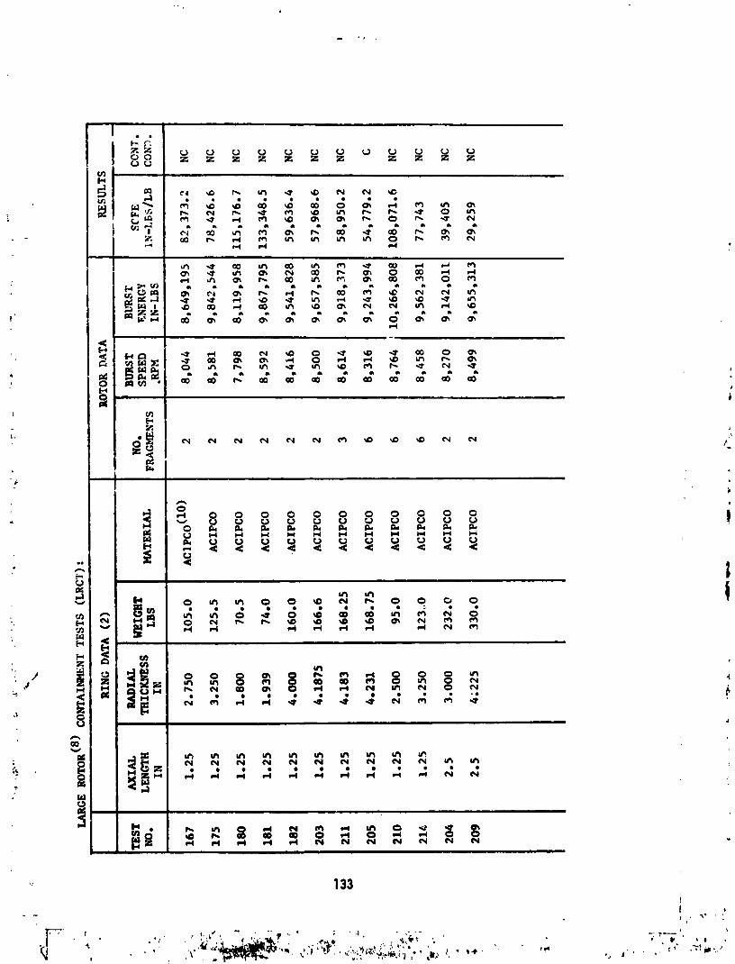
.! / RESULTS AND DISCUSSION_"
_ A compendium of the pertinent test and calculated data used inthis report are presented in Appendix A.
The results of test are presented in plotted form in Figures 6_
: 7, 8, 14 and 15. These plots are actually p]2me sections of eheconceptual three dimensional (variable) plot shown In Figure 3, but .:
,_, in these instances using the test data developed. The intent hereis to clearly show, vhere possible, the functional relationshipbetween the SCFE and the significant test varinbles: inner ring
: dlaneter (IDR); number of fraliments (NF)! and rlng axial length (ALR).
a. SCFE - NF Relationship for Small Rotors; Figure 6. Itcan be seen from these curves that for small rotor containment the
SCFE is for all practical purposes independent of the number of pie-sector shaped fragments generated at burst. This indicates that
rings of the same weight would be required for contalnment regardless
of the number of fragments generated at rotor burst in the range of
from 2 to 6 fragments and having a total (translational and rotational)
energy contest of approximately 106 In-lbs. A corollary to this would
be that a worst fragment number condition for small rotor contain-ment with respect to ring weight does not exist.
b. bCFE - ALR _[elationship for Small Rotors; Figure 7. The
relationship shown in this Figure indicates that an optimum
value for ring axial length exists. For the size rotor tested, an
optimum lightweight ring for containment is derived when the axialiengtt,of the ring is made equal to that of the rotor; that iswhere ALR = i.
c. SCFE - IDR Relationship for 2, 3 and 6 Fragment Bursts
at ALR = i; Figure 8. First of all, these relationships are
_ incomplete except for the 6-fragment data because the radial thicknessrequired for large rotor containment of the 2 and 3-fragment bursts
exceeded that which was available from inventory (4130 cast steel
circular rings with an ID of 31.64 inches (0.804 m) and having a
'_ maximum radial thickness of 4.1875 inches (.106 m)). The relation- i
ship shown in Figure 8 indicates that the amount of fragment energy ithat a pound of ring material can contain decreases when the rotor
f
size and energy content increases; that is for the same ring to
rotor axial length ratio, ring materials and number of fragmentsgenerated at burst, the containment capability of the larger ring,
: as measured by the SCFE (on a contained energy per unit weightbasis) is lower than a small ring. This indicates that the practice
of extrapolating small rotor containment ring results to large rotor
containment ring applications would be very tenuous. To provide some, feel for the ring and fragment distortions that normally accompany
the containment process, the post-test conditions of rings and rotors"' from several selected tests (both contained and uncoatained) are
: shown photographically in Figures 9 through 13./
/_ d. SCFE - NF Relationship for Large Rotor Containment at, ALR = I; Figure 14. The relationship in this figure, though noto definitive because containment was not achieved for the 2 and 3
fragment burst, indicates that the SCFE is dependent on the number
of fragments (NF) generated at burst. This differs from the smell
rotor results, which indicated that the SCFE and NF were almost In-
dependent. The trend of this relationship indicates that the capability; of a ring increases as the number of fragments generated increases
or in other words, as th,e number of fragments generated at burstdecreases the containment situation with respect to ring weightbecome more adverse, i.e., more weight is required.
!
' " 116
._. , , v. _ . _ ...._V -_ _ ' n, _ :_Z-.--'---- • • ._ _ -_.
"1978002"125-'1"19
e. SCFE - ALR Relationship for Large Rotor Containment of
2_Fragment Bursts; Figure 15. Only limited tests were conducted to
expJore this relationship because trends indicated that the weightsof ring required for containment were becoming very high. Figure 15
tends to show that an optimum axial length might exist in the
neighborhood of ALR = i. This is consistent with the results
of the small rotor results, which because of the abundance of
test data, was more conclusive in indicating an optimum ALR = I.
f. General Observations and Results:
(I) Comparison Between Large and Small Rotor Containment
Ring Deformation/Displacement Characteristics During Fragment Impact:
Figure 16 shows high-speed photographic results that depict themechanics of large and small rotor containment in which a 3-fragmentrotor burst is involved. It can be seen from these data that the
gross deformations and displacements experienced by the steel rings
are quite independent of size. In fact, in a general sense, the
deformation/displacement characteristics for the large and small rotor
containment rings are approximately identical. On the basis of this
data, it was anticipated that a functional relationship between SCFEand rotor diameter/ring ID could be experimentally derived and be
generally applicable.
(2) Exploratory Tests of a Small Rotor Composite Contain-ment Ring: Data for these tests can be found in Appendix A under
test numbers 143, 144, 183 and 208. These tests were conducted using
the smaller T58 engine turbine rotors modified to burst into three
fragments at their design speed of 20,000 rpm and impact concentri-
cally, encircling rings that were made from three types of materials
or material configurations: (a) filament wound fiberglass in anepoxy matrix; (b) circular boron carbide segments backed by filament
wound fiberglass in an epoxy matrix; and (c) a segmented, hardened
4130 steel ring backed by filament wound fiberglass in an epoxymatrix. The fiberglass and steel-flberglass rings did not contain
the fragments; however, the boron carblde-fiberglass ring did
contain at a weight savings of 30% over an optimally configured
/ steel ring subjected to identical burst conditions° Post-test photo-_ graphs of these rings are shown in Figures 17 through 19o On the
basis of these exploratory tests, it appears that composite rings
may serve to reduce the weight penalty associated with rotor disk
fragment containment. To determine what these weight reductions
might be, will require an extensive program of experimentationusing multi-layered material rings.
l 117
, ,' _ ._,;"_"_'_' _ 1,,,. t l. _" I ' ,, I) " .I , ' ' I" ' )
• • ,_. _e_:' "',_ . , • _ ';, ' . , , . ' --,
"1978002"125-'120
REFERENCES
i. REPORT - Mangano, G. J., "Rotor Burst Protection Program - Phases
VI and VII; Exploratory Experimentation to Provide Data For The
Design of Rotor Burst Fragment Containment Rings", Naval Air
Propulsion Test Center, NAPTC-AED-1968 of March 1972 J
2. REPORT - Martino, A. A. and Mangano, G. J., "Turbine Disk Burst
Protection Study", Final Phase II-III Report on Problem Assign-
ment NASA DPR #RIO5, Naval Air Propulsion Test Center, NAPTC-AEL-
1848 of February 1967.
3. TEXT - Freberg, C. R. and Kemler, E. N., "Elements of Mechanical
V-_-h_ation", John Wiley & Sonce, Inc., New York, 1949 (Page 23).
4
g118 i
t,, 0
1978002125-121
ID 15 ! ID 32
' I"NF2 NF3 NF_ NF 2 I NF3 NFe
ALR'_ Ii I I
_ t--L 1
ALR JL I
t4 _ . I lIt.._L
ALR t_2 t__L
,_ t 4!
WHERE: ALR = RING TO ROTOR RIM AXIAL LENGTH RATIO(NUMBER DENOTES RATIO)
IO = RING INNER DIAMETER.i
(SUBSCRIPT DENOTES NOMINAL DIAMETER ,_IN INCHES)
t : RING RADIAL THICKNESS(SUBSCRIPT REFERS TO NO. OF TRIALS TO t
ESTABLISH CONTAINMENT THICKNESS)NF = NO. PIE SECTOR SHAPED ROTOR FRAGMENTS
(I) GE T58 Engine Power Turbine Rotor - Refer to Figure A-I fordimensional and physical details.
(2) SRCT Ring Diameter = 15.0 inches.
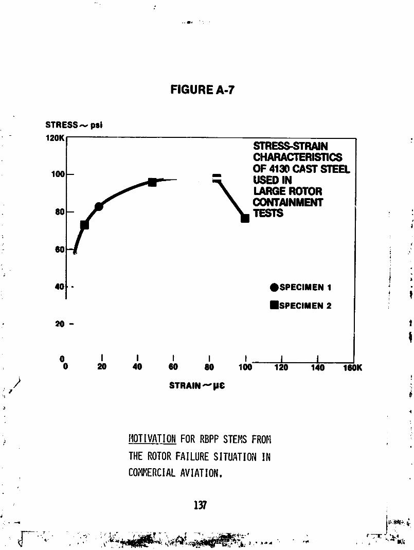
(3) NF - Centrifugally cast 4130 steel billet produced by NationalForge Company, refer =o Figure A-2 for stress-strain char.
(4) ACIPCO - C_ntrlfugally cast 4130 steel billet produced byACIPCO, refer to Figure A-3 for stress-straln char.
(5) Fiber Glass - Composite ring manufactured by Eshbaugh Cor-poratlon; construction - E-glass roving in an epoxy resin matrix.
(6) B/C-Glass - Composite ring manufactured by Reflective Laminates/Fansteel; construction - Boron Carbide segments backed wlthE-glass tape in an epoxy resin matrix (see Figure A-4).
First, was the Kevlar ring made with epoxy binding? Second, did you
ever test these rings with radial s,,_l)orts;don't you feel that not having
radial supports could be unconservative inasmuch as you allow the ring to
deform to a much greater manner than if it were part of a "long" container?
G.J. Man_ano, NAPTC
In answer to the first question, the Kevlar that we used was a fabric
wound on a diagonal with no binder. A thin inner aluminum cylinder was used
to provide shape.
Concerning the second question, some preliminary tests in which we
purposely added radial constraints were conducted. We found that it wasn't
a weight-effective configuration. That is, it weighed more than a freely-
supported ring that provided the same degree of containment for identicalburst conditions.
J. Meaney, Rohr
Well, the point I was trying to get at was that some of the rings that
you showed that actually contained the fragments were greatly deformed. But
if the ring had a "large axial length" and was supported on casing or bracket
; structure, would not this support influence the containment ability? '
G.J. Man_ano, NAPTC
That was why we went through the exercise of trying to determine the
optimum ring axial length with respect to weight. An optimum was found when
the axial length ratio between the rotor axial length and the ring axial length
was one. Ratios of one-half, one, and two were investigated for a one-inch wide
rotor. We evaluated the effect of axial length on the containment process and
found an optimum with respect to weight at a rotor to ring axial length ratioratio of one.
R. Bristow, Boeing
I would like to make a comment on that last question. A Kevlar shield
/ must deform quite a bit more than a steel shield, and we were worried about how# some of the aircraft structure might r_strain the Kevlar shield such that the ,
fragment punches a hole or chews its way through. We put some honeycomb material
._ behind the Kevlar on some of our tests to simulate the sound suppression material. !
On some of these, we had two layers of sixteenth inch aluminum with honeycomb iin between, so that the whole honeycomb panel was about an inch thick. The
Kevlar did not fail under that condition; it blew the honeycomb apart and
% continued to expand. These were ballistic type impact tests, not engine rotorburst" impacts.
B.L. Koff, GE-Cincinnati
These disk impact tests were conducted by bursting a rotor between two
' 143
L _ • ¢" " ' '
4 ; .,_; _ • ,_ '_ ",
1978002125-146
steel plates and having the segments impact on a steel ring. In an actual engine,
that ring cross-section is not held rigidly and would roll and let the disk segmentsslip by. As a result, it would take three or four tLmes the ring weight if the
axial length effect is included to achieve containment, because in the engine the
disk is not guided between two solid steel plates. The disk moves radially out-
ward but the fragment could twist the ring and deflect right past it. That'sone point.
The second point is that if you're talking about containing turbine disks,
it seems that you should only experiment with materials (if you're going to
pack it down tight around the rotor) that can take the temperature environmentin the turbine section of the engine.
G.J. Mangano, NAPTC
Yes, I agree. These tests are somewhat abstract; they are not intended
to provide final design information, but rather to explore containment ring
behavior under conditions of actual engine rotor fragment attack. Because
this was a first attempt at providing general design guidelines, it didn't
take into account more specific variables such as engine mounting effects,temperature effects, etc. i
S. Sattar, P&W
To follow up the previous question -- in an engine, you may not get an
axisymmetric failure where fragments are trying to load the ring in a hydrostatic
pressure manner. Quite often the fragments want to apply not only hydrostatic
pressure on the ring, but want to twist it. If you had supported the contain-ment ring in the manner that the engine sees it, quite often I think a Kevlar
ring which might be very effective to contain pressure, may buckle under the _very large torque loads that these pieces will impart. An engine rotor may
not burst perfectly; all the pieces may not be released. You might lose maybe
one-third of it in pieces, and the other two-thirds might stay on the rotor.
. I wonder if you'd like to comment on that. _
G.J. Man_ano, NAPTC
High-speed photo results taken of the containment process and examination
of the rings after testing indicate that ring loading by a symmetrical rotor
• burst is not hydrostatic. In fact, highly local and considerable bending of
the ring occurs outwardly at the disk impact sites and inwardly at points
approximately midway between the impact sites. A symmetrical three-fragment/iA
/ burst, for example, will cause six local bending sites: three inward and
' _ three outward. For two-, three-, and six-fragment sywmetrical bursts, the '_
loading is symmetrical to be sure but is far from being what can be considered
hydrostatic. This is evident from Figs. 9, I0, II, and 16 of our paper. As
the numbers of fragments involved in the burst increases much beyond six, the
ring loading would tend to be hydrostatic, but within the scope of our experience,
highly fragmented disk bursts in service tend to be the exception rather than the_- rule.
I have no direct experience with the mechanics of asymmetric burst contain-
ment, but it would seem that this type of failure would more likely load larger
areas of the ring in a hydrostatic manner than would a symmetric burst.
In order to minimize the weight of ring used for containment, whether
it is made of steel or Kevlar, the ring should be allowed to deform and
displace freely during the fragment interactions so as to take maximum
advantage of the energy that can be absorbed in the distortion process.
Where weight is to be minimized, this concept dictates that the ring installa-
tions on an engine should approach that which was used for test; namely, freely
supported. Under these conditions the Kevlar ring did admirably well in con-
taining the fragments at minimum weight.
P. Gardner, Norton Co.
Why did you limit your studies of Kevlar to Kevlar 29 and not 497
G.J. Man_ano, NAPTC
We did only exploratory testing of Kevlar: Boeing has provided us with
the rings. We have conducted only four or five tests to date. Kevlar 29 was
supplied and used.
• J.H. Gerstle, Boein_ #
I might just add a comment to that. Boeing has tested both Kevlar 29and 49. We did not see substantial differences.
J
i A. Weaver, P&W ! /
" Concerning the weight effectiveness, with the increased axial widths of
your rings, above the ratio of I:I that you cited, although the long rings are _!i
heavier, did the actual thickness for threshold containment decrease when icompared with the I:i ratio case?
!G.J. Man@ano, NAPTC
Thickness required for containment at an axial length ratio of 2 was
greater than for a ratio of I. This is a surprising result, i
• Sol Weiss, NASA-Lewis
AS you presented the containment data on the small wheel, I got the
impression (I think you said this) that apparently #/le threshold containment
weight did not depend upon the number of equal-size fragments. I think
yesterday we heard some people intuitively say (and I think we all believe
this) that if you decrease the size of the fragments and increase the number
of fragments, you may have a better opportunity for containment at lower
containment ring weight. Now, when you went to a large wheel, it seems thate,
? _ the number of fragments did have an effect upon containment .capability. Now,with what we've done so far, can we conclusively say, that the number of
fragments did not affect containment in _e small wheel tests, but did in the
large wheel tests?
G.J. Sag_ano_ NAPTC
For the small-rotor containment tests, the results definitely indicate
an independence between the weight of ring required for containment (or SCFE)and the number of fragments generated at burst. The large rotor test results
tend to indicate the opposite. ,
l
p
i 145
:'!%[-,7--7....... ,..,..,......,. ,,- .. ,
i
1978002125-148
A.K. Forney, FAA
Guy, if I may, I'd like to go back to the motivation portion of your
presentation because I'd hate to have these experts leave here with an
incorrect impression about the FAA sitting on all of this beautiful data.
First, I'd like if you could, to put your slide back up that shows the causes
of the uncontained rotor bursts. Could you, I'm going to ask you to show two
things: one that SDR, and second: your causes.
Now, since he's found the SDR I'll go ahead with it first. I wanted youp
to see that you get very little info_.ation on an SDR; here you see just about
all that you really ever get. Now, a few things about it that maybe you wanted
to know. This one is "open"; it does me_ that there will be a subsequent report.
It says "under investigation" so that theze will be another one that will close
it. All three of these happen to be open and so we do get a subsequent report;
it's interesting what some of these subsequent ones say. This one could very
well say "engine torn down and inspected, insufficient stall margin". We have
a little difficulty determining how the airline's overhaul shop determines b)"
inspection that the hardware had an insufficient stall margin (that it obviously i
did have insufficient stall margin under the conditions that caused it'to stall).
We in FAA engineering have found that we cannot use the SDR's to provide us with _ ;
any engineering information. All the SDR's can do is tell us that something
happened, and if we want to get details, we really do not depend on the SDR. J
Now there are several reasons. One is they don't have very much more detail ,,
than you see here. Secondly, all of this is fed into a computer and the computer
is not programmed, for example, to :et us pull out "uncontained failures". So
- if it does not specifically happen to mention it (and frequently you can't tell •
from the SDR whether the rotor failure was contained or not) the SDR really is
of no value there. Then (and maybe I should have started out here) these things
are submitted by an air carrier (that's the FAA term for airlines). They are
required by the regulations to report certain things that occur, and one of the
things they are req-:red to report is all of the in-flight shutdowns of engines.
NOW, it's interesting, what is in-flight; there's a fuzzy area. If somethingrequires them to shut an engine down before rotation, then some of the airlines
don't record it; it wasn't in-flight so it wasn't an in-flight shutdown. But
you know, we're interested in what happens to the engines just the same but
we don't often get the reports. So having made my comment, I would like to
ask you how you determined the causes. Did you attempt to determine the causes
from SDR's, or did you do it like we do, use the SDR to alert yourself to an
incident and then go back not even to the airline but to the engine company?
; / Experience has shown us that we get the best information on what really happened
•_:J and what the causes were by going back to the engine manufacturer whose enginewas involved. I do not know enough of your work to know how you' re doing that.
6
G.J. Man_ano_ NAPTC
Let me explain our procedures to you. I agree with you, there isn't
very much information in the SDR, but there is enough to give us some measure _J
/ of what's happening. When there's any controversy as to whether or not afragment was contained or if fragments were generated, we just don't include
it in our analysis. We operate to the limits of what the SDR has to offer,
nothing more. If the SDR doesn't have the cause (and this is FAR data), if it
doesn't stipulate what the cause is, then we do not use it. This is evidenced
, 4
1 146
]978002]25-]49
by the preponderance of "unknowns" that we nave here; the "unknown" category
is far and away the largest category. We compile data to the level of what
the SDR provides. However, this compilation gives a reasonably good indication
of what's going on. I do not think that our compilation is nearly as extensive
as that of the SAE committee; theirs is a very fine effort, and a very welcome
one. Our tabulation is intended to keep our finger on the pulse of the situa-
tion; the data are no better than the information provided by the FAA. Now,
Bob DeLucia is in charge of reducing this information, I would like to ask if
he has any comments to make.
R. DeLucia, NAPTC
I'd just like to address one point. As of June of last year we got
together with the FAA in Washington and explained the problem that we're
having identifying uncontained rotor bursts. They are sympathetic and as of
last year, they have included a code letter T, which means "engine case punc-
tured". So any subsequent SDR, say from about last June to the present will
have a code letter "T" in the computer runoff sheet if a fragment penetrated
the engine ca_ing and came out.
f
A.K. Fornez, F._A_
I would like to express publicly my appreciation to the Navy for that.
First of all, I didn't know that; I'd be interested in knowing who in FAA ,/L
headquarters you talked to. But our maintenance people, not engineering,
looked after this program. When the SAE Committee's activities started, we
asked them to pull out of the computer all of the uncontained failures, and . .
,: they couldn't.. We tried officially from engineering and maintenace to getthe program changed to identify uncontained failures, and we were unsuccessful. , 'So the fact that you now have done it, I want to express my appreciaticr "
. publicly, but I'd like to know who you did it with so I can find out thedetails of it.
G. Gunstone, CAA-FAA; l
I would just like to say that the last question reinforces yesterday's
plea that the constructors should get together to supply a consistent set of
data which could be used by all. We are all fumbling around with insufficient,
incomplete,, inaccurate data. It is quite silly that we should be "_n that
position, and I hope that a strong recomm_endation for a consistent data input
will come from this meeting.4
y / H. Garten, GE-Lynn k
•_. I would just like to reinforce some of the other technical comments about_ the tests. It seems to me that the first series of tests with the small turbine
"' wheel were really hydrostatic tests. If you had bothered to measure the length
of the shield after testing, you might have found that it was quite long, (oircum-
ferentially long) as compared to the original circumference, because most of the
strain energy went into tension. Now, when you got to the larger rotor, you had
_" to build your ring shield very deep, and the shield failed before it ever could
: support the hydrostatic load in tension, and it failed in bending. So I Just
wonder if you had considered comparing a metal shield with a Keval shield, build-
ing a metal shield in layers so that you would get more strain energy, into tension
: and less strain energy into bending?
, 147
• _.
, ,._ .... _ _ ., _-_ ,, , .,
1978002125-150
!
'9'#,;e
G.J. Man_ano, NAPTC
Herb, in fact, we did run layered rings. The results were not presented
here because those tests were exploratory and not part of a systematic testing
effort. As an abstract idea they worked well but appear not to be a practical
configuration.
J.H. Gerstle, Boeingj
I'd like to make a comment about the separate-rings tests -- I happen to
have se._ those three concentric rings which the Navy tested, and which worked.
I believe that the three rings responded similarly to a Hopkinson bar apparatus
with the outer ring doing the momentum trapping. That is, the stress waves will
first propagate in the thickness direction of the three rings and will be
trapped in the outer ring after it separates, causing it to break while leavingthe second rang intact. However, this is not a practical method.
G.J. Man_ano, NAPTC
There was a qu£stion about the relative ductility of the ring material
for the small rotor vs. the large rotor containment tests./
As a matter of fact, I think the materials used for the large rotor tests
were less ductile. We have some curves and t_zey're contained in the paper.
The material was centrifugal cast 4130 steel Mandom samples of the material
- were taken and subjected to standard ASTM X-ray tests for defects -- none were
found. We were concerned about porosity problems. We ran some containment tests
on wrought steel rings, and found large rotor threshold containment at a weight
of about 135 pounds vs. about 168 pounds for the cast 4130 steel. We did not
use titanium for containment tests. As someone mentioned, containment testing
under high temperature conditions would be useful.
What we'd like to do to close the loop is, perhaps, run a few more base-
line tests using a better steel, perhaps such as a wrought alloy that isn't
subject to defects and has better ductility. Then we plan to go on to composites,
which Art Holms is going to cover, in a paper later on. We shall explore Kevlar.
We are not looking at a particular design but want to provide generally applicable
guideline information that will be useful. We would welco,e your comments on how
we can make the tests more realistic without incurring excessive costs, and with-
out focussing on a particular application or problem. We are looking for rules
._ / that will be generally applicable and useful to the aircraft community.
H. Garten, GE-Lynn
I don't know why you're not looking at titanium because titanium is incorpo-
rated in some of the fan engines.
; G.J. Man_ano_ NAPTC%
We agree with you and Denis McCarthy that titanium does appear to merit
: attention for containment applications. Some selected testing would be useful.
A. Holms_ NASA-Lewis
I have a comment. One question dealt with unsymmetrical bursts. It seems
!
to me that the symmetrical burst is the more severe test of the ring. Mainly
with an unsymmetrical burst, you probably have one piece flying out with a
lot of translational energy and velocity, but the big piece has a lot of
stored rotational energy which it can give up over a longer period of time,
dissipating its energy with rubbing friction. So it seems to me that an
unsymmetrical burst would be a less severe test than a symmetrical burst.
On the question of the X-rays of the castings, the pieces that were
X-rayed were about one and a quarter inch thick with the X-ray beam going
through the one and a quarter inch direction. I think that was a reasonable
nondestructive test of the material. It is true that the larger castings
were more difficult castings than the small castings. The elongation in the
tensile specimens from the small casting was quite a bit larger than theLelongation from the large casting specimens. That may explain our size
effect. But, on the other hand, workers in fracture mechanics often do find
size effects in the work they do.
The body armor data that's been gathered by the Dept. of Defense shows
that titanium is much superior to most steels for high velocity impact in therange of 2,000 or 3,000 feet per second. Put if you get down around 500 feet