HIGHLY RECOMMENDED FOR THIS PROJECT:Service Manual or Assembly instruction manual for year of car getting the gauge installation. Wiring diagram for that year Corvette
STEP 1. Remove your factory LCD gauge unit from your dash panel.
a. Remove the headlight switch
b. Position steering wheel tilt all the way down
c. Remove tilt lever arm
d. Remove the seven screws on side and front of steering and gauge bezel.
e. Remove the five screw holding the information and radio bezel in place.
f. Remove the four screws holding in the gauge cluster.
12V
Part Includes Digital Dash PanelSmoked Lenses1 - Water Temperature Sending Unit
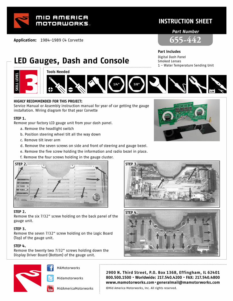
STEP 2. Remove the six 7/32” screw holding on the back panel of the gauge unit.
STEP 3.Remove the seven 7/32” screw holding on the Logic Board (Top) of the gauge unit.
STEP 4. Remove the twenty two 7/32” screws holding down the Display Driver Board (Bottom) of the gauge unit.
STEP 5. Remove the stencils and rubber blocks from the edges of the LCD displays.
STEP 6.Remove the six rubber clips holding the lenses down.
STEP 7. Remove the protective paper coating from both sides of the plexiglass lens.
STEP 6.
STEP 7.
STEP 5.
STEP 8.Insert lens into housing and reattach rubber lens clips.
STEP 9.Mount the Gauge Panel into the housing using the stock screws.
STEP 10.Pass the wires through the back of the housing through the now vacant odometer cutout and reattach the back of the housing.
STEP 11. Wire gauges and sending units into designated areas as instructed below.
WIRING INSTRUCTIONSConnect the BLACK ground wire to a designated ground.
Connect the RED wire to a switched +12 volt source (ignition switch).
Connect the PURPLE wire to the parking lights switch to dim the LEDs 50% when the headlights are on.
Warning - Do not connect to the headlight rheostat control wire, nor the existing dimmer switch; the dimming feature will not work properly if you connect to these.
Connect the GREEN wire directly to the negative terminal of the ignition coil or a direct tach output lead from the distributor or electronic control module. If you are using an aftermarket capacitive discharge ignition system, such as MSD, you must use the designated “tach output” connection on the electronic box. Do not make any connections directly to the coil with this type of high performance ignition system. The default tach setting is for an 8-cylinder engine.
Connect the ORANGE wire on the dash panel to your factory oil pressure sending unit.
Insert the new water temperature sending unit in place of the original temperature sender. Do not use Teflon tape or other sealer on the new sending unit threads to avoid inaccurate temperature readings. Connect the BLUE wire on the Intellitronix dash panel to the new temperature sending unit.
Connect the WHITE wire from the Intellitronix panel to the sending wire from the original gauge harness. Connect the black wire to Ground and the Red wire to switched +12 volts.
On the 16 Pin Connector, C15 is the pickup wire for the speedo. You must use the small wire provided as a ground loop connecting D11 to D3 for the speedo to function properly. The speedo is factory calibrated for 8000 ppm.
Connect the two TAN/WHITE STRIPED wires to one of the two included push button switches. Mount the switch in a convenient location such as under the steering column, so that you can reset your trip odometer and access your other speedometer functions.
Connect the YELLOW wire to the factory fuel sending unit.
Connect the BROWN wire to the high beam indicator wire.
Connect the GREY wires to the corresponding turn signal indicator wire.
DIGITAL PERFORMANCE SPEEDOMETERYour Intellitronix dash panel is equipped with our Digital Performance Speedometer. This electronic speedometer displays speed and includes an odometer, trip meter, high speed recall, 0-60 time and V4 mile elapsed time (ET). It can be calibrated with the push of a button to adjust the speedometer for different tire sizes, wheel sizes and gear ratios. The single pushbutton is used by a quick “TAP” to switch from odometer to trip meter and then back again if so desired. The microprocessor can distinguish from a quick “Tap” to a press and hold which will reset the trip meter in trip mode or it will display the performance data if in odometer mode.
CALIBRATIONThe speedometer leaves the factory with an industry standard pre-set setting of 8000 pulses per mile. Chances are high that you may not need to recalibrate your speedometer. You may need to recalibrate the speedometer if you have changed the original tire size or rear end gear ratio. NOTE, Do not attempt to recalibrate your speedometer until after it is working properly and you have determined that the speed is incorrect. The calibration procedure will NOT correct a faulty installation or improper wiring. If you attempt to recalibrate your speedometer without making sure the speedometer is receiving pulses from the sending unit, the speedometer will display “Err” and go back to the factory default setting of 8000 pulses per mile.
To recalibrate, locate a measured mile where you can safely start and stop your vehicle. By running the vehicle over this measured distance, the speedometer will learn the number of pulses output by the speedometer sensor during a specific measured distance. It will then use this acquired data to calibrate itself for accurate reading. There is a small recall pushbutton in the center of the panel used to calibrate and read all of the data stored in the speedometer. After installing your speedometer according to the wiring instructions, with the ignition on it should immediately display the default screen of 0 MPH. You will then need to drive your vehicle to the predetermined measured mile. During this trip, the speedometer should read something other than 0 MPH. If it does not, return and locate the problem. Otherwise proceed with the calibration by stopping at the beginning of the measured mile with your vehicle running and in odometer mode and not trip mode, press and “hold” the pushbutton until the odometer displays “HI-SP”.
On its own, the gauge will then cycle through the recorded performance data in the following order: “0-60,” “1/4,” and “CAL.” While “CAL” is being displayed, quickly TAP the pushbutton briefly one time. This will put the speedometer in Program Mode. The letters “CAL” will be displayed on the 3 large digits and 0 will be displayed on the odometer digits. If you did not tap the button when the word cal was displayed, the pulses per mile will be displayed on the odometer and the display will go back to MPH mode. If you did TAP the button, you will now be setting this to a new number. This quick tap will let the microprocessor know that you wish to enter a new number and 0 will now be displayed. It is very important that you drive to the end of the measured mile and tap the button again.
WARNINGIf while in “CAL” mode you do not move at all and press the button again, the microprocessor will NOT have received any data whatsoever and the unit will display “Err” and revert back to the factory setting of 8000 pulses per mile. At a minimum, drive some distance and you can always go back and start again if need be.
If you miss stopping the display at “CAL”, simply repeat the steps. With “CAL” displayed, the speedometer is now waiting to record the pulse count data accumulated over the measured mile. When you are ready, begin driving and you will notice that the reading will start counting up. The odometer will display the incoming pulse count. Drive the vehicle through the measured mile (speed is not important). As you move, the odometer will begin showing the speedometer pulses as they are being counted. At the end of the mile, stop and press the pushbutton again. The odometer will now display the new number of speedometer pulses that were registered over the distance. The odometer will continue to display the pulse reading for a few seconds. Once it reverts to the default mode, you have calibrated the speedometer.
TRIP DISTANCEA single tap of the recall button will activate the trip meter in the odometer display. A decimal point will appear to indicate that you are in trip meter mode. Holding the recall button down for several seconds will clear the trip distance. To return to the default odometer display, “TAP” the recall button again. The decimal point will disappear to indicate that you are back in the default odometer display.
RECORDING AND VIEWING PERFORMANCE DATAFollow these steps to record and recall Performance Data (high speed, 1/4 mile ET and 0-60 time):
STEP 1.Before each run your car must be at a complete stop at the starting position. Press and hold the pushbutton as it cycles through the performance data. At the end, the odometer will “RESET” and all performance data will be cleared from memory. This will not affect your stored calibration value or the odometer reading.
STEP 2.Now press the pushbutton until “HI-SP” is displayed. On its own, the gauge will cycle through the performance data that it records in the following order “0-60”, “1/4’”, “CAL”
STEP 3. Start the run, pass, session, etc.
STEP 4.When finished, repeat Step 2 to view the data gathered from this run. While stopped, you can view this data as many times as you wish. However, once it finishes scrolling one time, the memory is ready to record new data for the 1/4 mile and 0-60 mph times and will begin recording again once the vehicle starts moving.
STEP 5.The highest speed measured over multiple runs will be retained in memory.