FAILURE OF CONCRETE DAMS by Dr. Charles L. Bartholomew* INTRODUCTION : There have been several studies of dam failures published in the last 30 years. Of these, the most comprehensive is the 1983 volume by Jansen 1 published by the U. S. Bureau of Reclamation. That study listed and discussed dam failures that have occurred over the past 900 years. Of the more than 150,000 dams worldwide that represented significant hazards to life or property, only about 2000 have failed over the last 9 centuries, and most of those failures were not major dams. During the 20th century, there have been about 200 notable failures resulting in the loss of over 8000 lives. Of these 200 dam failures, less than 40 have been concrete or masonry dams. HISTORICAL FAILURES: Tables 1 and 2 list information on significant concrete and masonry dam failures. Many of these failed facilities have been successfully rebuilt and are operating in a satisfactory manner. The tables show that (eliminating acts of war) nearly all of *professor and Chairman, Dept. of Civil Engineering, Widener University, Chester, Pennsylvania 19013= I)Numbers refer to entries i.nthe BibliwraPhY 428
Transcript
FAILURE OF CONCRETE DAMS
by
Dr. Charles L. Bartholomew*
INTRODUCTION :
There have been several studies of dam failures published in
the last 30 years. Of these, the most comprehensive is the 1983
volume by Jansen 1 published by the U. S. Bureau of Reclamation.
That study listed and discussed dam failures that have occurred
over the past 900 years. Of the more than 150,000 dams worldwide
that represented significant hazards to life or property, only
about 2000 have failed over the last 9 centuries, and most of
those failures were not major dams.
During the 20th century, there have been about 200 notable
failures resulting in the loss of over 8000 lives. Of these 200
dam failures, less than 40 have been concrete or masonry dams.
HISTORICAL FAILURES:
Tables 1 and 2 list information on significant concrete and
masonry dam failures. Many of these failed facilities have been
successfully rebuilt and are operating in a satisfactory manner.
The tables show that (eliminating acts of war) nearly all of
*professor and Chairman, Dept. of Civil Engineering, Widener
University, Chester, Pennsylvania 19013=
I)Numbers refer to entries i.n the BibliwraPhY
428
Name of Dam
Alla Sclla Z.crbino
Austin
Bouzcy (masonry)
Dujeproatroj
E&r
Eigiau
Khadakwasla(masonry)
Mohne
Puentc5(masonry)
~gm (masonry)
TABLE 1
CONCREE! AND MASONRY GRAVITY DAMS
Location Heitit [Ftl Year of Failure
Italy
Pennsylvania
France
Russia
Germany
Wales
India
Germany
Spain
India
39 1935
so 1911
72 189s
131 1941
157 1943
35 1925
131 1%1
132 1943
164 1802
86 1917
Aw at Failure firs)
12
1.8
14
unkncnvn
29
17
82
32
11
0.2s
Probable Cause of Failure
Foundation seepage, sliding and overturning
Foundation sliding and concrete cracking
Uplift andinternalhydrostaticpressures
Destroyed in war
Destroyed in war
seepage under dam
Uplift pressures and internal cracking
Destroyed in war
Seepage under dam
overtopping and sliding
Name of Dam
Gknol
Malpassct2
abutment
St.Francis3
&Vaiont4
wo
Vega de TeraS
TABLE 2
CONCR151’EDAMS OTHER THAN GRAVllY TYPE
LOcatioq lMJWI!) Y=r of Failurq Probable Cause of Faihq
Italy 143 1923 05 Poor dcaign and workmanship
France m 1%9 5 Weak abutment roclGhigh water pressure in
1-Multiplearchandgravity
2-Arch
3-Amhed/gravity
4-Arch
5- Buttress, ma.wnry,and slab
California 20S lm 2 Poor foundation, internalcracking
Italy 869 1963 3 Overtoppingcaused by rockslide in resewoir
Spain 112 1959 2 Leakage in joints, foundation sliding
these failures resulted either directly or indirectly from
foundation or abutment problems.
The fact that there are many more failures of earth dams
than concrete dams is primarily due to three factors: (1) There
are many more earth dams; (2) Concrete dams are typically built
on more stable foundations; and (3) Concrete is an inherently
stronger material than earth fill.
Concrete dam failures do, however, occur and typically
result i.nmassive property damage and significant loss of life.
FAILURE CLASSIFICATION:
It is important to distinguish between types of failure.
The failure may be either structural or functional (or both). A
structural failure refers to active failure by cracking,
breaking, sliding or overturning such that the dam itself is
damaged, while a functional failure refers to a condition wherein
the dam is no longer able to perform its function (i.e. retain
water) . Structural failures commonly are very newsworthy and
typically result in damage downstream, while functional failures
usually are scheduled for repair or modifications. Functional
failures include situations such as excessive seepage,
malfunctioning valves or gates, etc. A functional failure can
become a structural failure and all structural failures are also
functional failures.
EVIDENCES OF DEFICIENCIES:
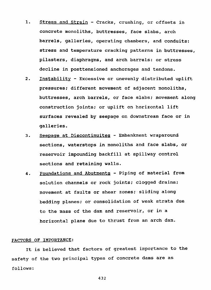
Common evidences of deficiencies in concrete dams include:
431
1. Stress and Strain - Cracks, crushing, or offsets in
concrete monoliths, buttresses, face slabs, arch
barrels, galleries, operating chambers, and conduits:
stress and temperature cracking patterns in buttresses,
pilasters, diaphragms, and arch barrels: or stress
decline in posttensioned anchorages and tendons.
2. Instability - Excessive or unevenly distributed uplift
pressures; different movement of adjacent monoliths,
buttresses, arch barrels, or face slabs; movement along
construction joints; or uplift on horizontal lift
surfaces revealed by seepage on downstream face or in
galleries.
3. SeeDaqe at Discontinuites - Embankment wraparound
sections, waterstops i.nmonoliths and face slabs, or
reservoir impounding backfill at spillway control
sections and retaining walls.
4. Foundations and Abutments - Piping of material from
solution channels or rock joints; clogged drains;
movement at faults or shear zones; sliding along
bedding planes; or consolidation of weak strata due
to the mass of the dam and reservoir, or in a
horizontal plane due to thrust from an arch dam.
FACTORS OF IMPORTANCE:
It is believed that factors of greatest importance to the
safety of the two principal types of concrete dams are as
follows:
432
1. Concrete Arch Dams - Because of the monolithic behavior
of arch dams, horizontal displacement due to arching
thrust forces against the abutments is of great
importance. Also important are seepage flows,
foundation movement and relative movement at any joint
in the dam or foundation.
2. Concrete Gravitv Dams - It is important for a gravity
or buttress dam to maintain its structural integrity
and remain stable against sliding. Relative movement
at joints and cracks, seepage flows, and hydrostatic
uplift are also very important.
EXAMPLE - AUSTIN DAM:
As indicated in Tables 1 and 2, only two major failures of
concrete dams in the United States have resulted in significant
loss of life and massive property damage. Those dams are the
St. Francis Dam in California which failed i.n 1928 resulting in
the loss of 450 lives and the Austin Dam in Pennsylvania which
failed in 1911 with about 80 lives lost. Much has been written
about the St. Francis failure, but relatively litte attention has
been paid to the Austin Dam failure. A detailed discussion of
that failure follows.
Austin Dam is located in western Potter County in north-
central Pennsylvania as shown in Figure 1. The dam was built
across Freeman’s Run in mountainous terrain about 1.5 miles north
of the town of Austin. The town of Costello is located about 3
miles south of Austin. Freeman’s Run has a drainage area of
433
New York
Ohio/\
%3-’I/
\\
I \pottercOunt Y
Freeman’s Run
f?
N.J.
Narth
Austin I
Costel 10 First Fork
BranchSusquehanna R.
LOCATION MAP
FIG. ~434
about 35 square miles upstream from the dam. Waters from
Freeman~s Run eventually enter the Susquehanna River and then
flow to Chesapeake Bay.
As shown in Figure 2, an earlier dam was built on Freeman’s
Run in 1899. This old dam was about 20 feet high and was
constructed of timber grillage filled with rock and soil and then
topped with compacted earth. The old dam impounded about 25
million gallons of water for use at the Bayless Pulp and Paper
Co. Mill located in the valley between the dam and the town of
Austin. The valley walls are relatively steep, rising about two
hundred feet above the valley floor. The Bayless Co. needed
additional water reserves for dry weather, so in 1909,
Mr. T. Chalkley Hatton, a noted engineer from Wilmington,
Delaware was hired to design a new high dam to impound at least
200 million gallons of water. The dam was designed and
construction was completed on Dec. 1, 1909. Statistics on the
dam are given in Table 3. This data was obtained from an
Engineering News2 article published in 1910.
It is interesting to note that the original design called
for an 8-foot deep keyway, but the owner, in an effort to reduce
costs reduced the size to only 4 feet. The designer then
required the compacted earth fill on the upstream face in an
attempt to reduce underseepage. The foundation rock was hard
sandstone, but contained many thin interbedded shale layers which
appeared to soften rapidly when exposed to free water. The
foundation was cleaned to a hard sandstone surface prior to
placement of concrete. Good workmanship was reported.