8
1995 Nissan-Datsun Sentra L4-1998cc 2.0L DOHC MFI (SR20DE) Timing Chain: Service and Repair Fig. 5 Timing Chain Replacement (Part 1 Of 2) Refer to Fig. 5 when replacing the timing chain.

1995 Nissan-Datsun Sentra L4-1998cc 2.0L DOHC MFI (SR20DE)
Timing Chain: Service and Repair
Fig. 5 Timing Chain Replacement (Part 1 Of 2)
Refer to Fig. 5 when replacing the timing chain.

Fig. 16 Valve Cover Bolt Removal Sequence
Fig. 17 Camshaft Timing Mark Alignment
Fig. 18 Camshaft Bracket Bolt Removal Sequence

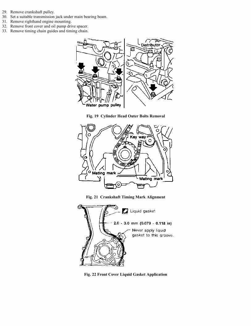
Fig. 19 Cylinder Head Outer Bolts Removal
Fig. 20 Cylinder Head Bolt Removal Sequence
REMOVAL1. Release fuel system pressure as outlined under Technician Safety Information.2. Remove engine undercover.3. Remove righthand wheel and engine side cover.4. Drain engine coolant and oil.5. Remove radiator and shroud assembly.6. Remove air duct to intake manifold.7. Remove drive belts.8. Remove water pump pulley, alternator and power steering pump.9. Remove necessary vacuum, fuel and electrical connections. Label hoses and connectors for installation reference.
10. Remove spark plugs and cables.11. Remove valve cover and oil separator, Fig. 16.12. Remove intake manifold supports.13. Remove oil filter and power steering pump brackets.14. Set No. 1 cylinder at TDC on its compression stroke, then rotate crankshaft until mating marks on camshaft sprockets are aligned as shown in
Fig. 17.15. Remove chain tensioner.16. Remove distributor, then the timing chain guide.17. Remove camshaft sprockets.18. Using sequence shown in Fig. 18, remove camshaft brackets.19. Remove camshafts, oil tube and baffle plate.20. Remove water hose for cylinder block and hose from heater.21. Remove starter motor, then the water pipe bolt.22. Disconnect knock sensor harness connector.23. Remove EGR tube.24. Remove cylinder head outside bolts, Fig. 19.25. Using sequence shown in Fig. 20, remove cylinder head bolts in two or three steps.26. Remove cylinder head with manifolds attached.27. Remove oil pan as outlined under Oil Pan, Engine.28. Remove oil pan strainer and baffle plate.
29. Remove crankshaft pulley.30. Set a suitable transmission jack under main bearing beam.31. Remove righthand engine mounting.32. Remove front cover and oil pump drive spacer.33. Remove timing chain guides and timing chain.
Fig. 19 Cylinder Head Outer Bolts Removal
Fig. 21 Crankshaft Timing Mark Alignment
Fig. 22 Front Cover Liquid Gasket Application

Fig. 23 Cylinder Head Bolt Measurement
Fig. 24 Cylinder Head Bolt Tightening Sequence
Fig. 25 Lefthand Camshaft End Bracket Liquid Gasket Application
Fig. 26 Camshaft Bracket Installation Direction

Fig. 26 Camshaft Bracket Bolt Tightening Sequence
Fig. 27 Installing Chain Tensioner

Fig. 29 Valve Cover Bolt Tightening Sequence
INSTALLATION1. Install crankshaft sprocket on crankshaft.2. Position crankshaft so that No. 1 cylinder is at TDC.3. Align gold mating mark on timing chain to crankshaft sprocket, then install timing chain on crankshaft sprocket, Fig. 21.4. Install timing chain guides.5. Before installing front cover, remove all traces of gasket material on all mounting surfaces.6. Apply a bead of liquid gasket to mounting surface of front cover, Fig. 22.7. Install oil pump drive spacer and front cover. Ensure mating marks on timing chain and crankshaft sprocket align.8. Remove excess liquid gasket.9. Install front engine mounting bracket.
10. Install crankshaft pulley and set No. 1 cylinder at TDC on its compression stroke.11. Install oil strainer and oil pan baffle plate.12. Install oil pan as outlined under Oil Pan, Engine.13. Remove all traces of gasket material from mating surfaces of cylinder head and cylinder block.14. Prior to installing cylinder head bolts, ensure dimension "A" shown in Fig. 23 is less than 6.23 inches.15. Install cylinder head bolts, then using sequence shown in Fig. 24, tighten as follows:
a. Torque bolts to 29 ft. lbs.b. Torque bolts to 58 ft. lbs.c. Loosen bolts completely.d. Torque bolts to 25-33 ft. lbs.e. Turn bolts 90-100° clockwise.f. Turn bolts an additional 90-100° clockwise.
16. Install cylinder head outside bolts, Fig. 19.17. Install EGR tube.18. Connect knock sensor harness connector.19. Install water pipe bolt.20. Install starter motor.21. Install water hoses.22. Remove all traces of gasket material from lefthand camshaft end bracket and apply a bead of liquid gasket to area shown in Fig. 25.23. Install camshafts by positioning lefthand camshaft keyway at about the 12 o'clock position and righthand camshaft keyway at about the 10
o'clock position. Install oil tube and baffle plate.24. Install camshaft brackets as shown in, Fig. 26.25. Using sequence shown in Fig. 27, tighten bolts as follows:
a. On righthand camshaft, torque bolts 9 and 10 to 1.4 ft. lbs., then bolts 1 through 8 to 1.4 ft. lbs.b. On lefthand camshaft, torque bolts 11 and 12 to 1.4 ft. lbs., then bolts 1 through 10 to 1.4 ft. lbs.c. On both camshafts, torque bolts described in steps a or b to 4.3 ft. lbs.d. Torque, bolts marked A, B and C to 8.7 ft. lbs.e. Torque bolts marked D to 13-19 ft. lbs.
26. Align silver mating mark on timing chain with marks on camshaft sprockets, then install camshaft sprockets.27. Lock camshaft using a suitable wrench on flats of camshaft and torque camshaft bolts in two steps to 101-116 ft. lbs.28. Install timing chain guide.29. Install distributor. Ensure after installing distributor, distributor rotor is positioned at No. 1 cylinder spark position.30. Press cam stopper down and press in sleeve until hook of chain tensioner can be engaged on pin, Fig. 28. Ensure arrow marked A faces front
of the engine.

31. Install filter and power steering pump bracket.32. Install intake manifold supports.33. Install valve cover, then using sequence shown in Fig. 29, tighten nuts as follows:
a. Torque nuts 1, 10, 11 and 8 to 2.9 ft. lbs.b. Torque nuts 1 through 13 to 7.2 ft. lbs.
34. Reverse remaining removal steps for installation procedures.


