100
V-GLIDE 36-VOLT VEHICLES MANUAL NUMBER 101968406 EDITION CODE 0199A00000 1998-1999 MAINTENANCE SERVICE SUPPLEMENT

V-GLIDE36-VOLT VEHICLES
MANUAL NUMBER 101968406EDITION CODE 0199A00000
1998-1999
MAINTENANCES E RV I C ESUPPLEMENT


FOREWORD
The Club Car V-Glide 36-volt electric vehicle is engineered and built to provide the ultimate in performanceefficiency. However, timely and appropriate vehicle maintenance and repair is essential for long-term vehicleperformance and continued safe and reliable service.
This supplement provides detailed information for the maintenance and repair of V-Glide 36-Volt electric vehi-cles and should be used in conjunction with the 1998/1999 DS Golf Car Maintenance and Service Manual,Publication Part No. 101968401. If you do not have a 1998/1999 DS Golf Car Maintenance and Service Man-ual, you may order one from your local Club Car representative. This supplement and the 1998/1999 DS GolfCar Maintenance and Service Manual should be thoroughly reviewed prior to servicing the vehicle. The pro-cedures provided herein must be properly implemented, and the CAUTION, WARNING, and DANGER state-ments must be heeded.
This supplement was written for the vehicle mechanic who already possesses basic knowledge and skills inelectrical and mechanical repair. If the mechanic does not have such basic knowledge and skills, attemptedservice or repairs to the vehicle may render the vehicle unsafe. For this reason, Club Car advises all repairsand/or service be performed by an authorized Club Car distributor/dealer representative or by a Club Carfactory trained technician.
This service supplement, along with the 1998/1999 DS Golf Car Maintenance and Service Manual, covers allaspects of typical service requirements for the V-Glide 36-Volt electric vehicle. If you need additional informa-tion, you may write to us at: Club Car, Inc., P.O. Box 204658, Augusta, GA 30917 or contact a Club Car tech-nical service representative at (706) 863-3000, extension 3580.
©1999 Club Car, Inc.
Club Car and Armorflex are registered trademarks of Club Car, Inc.
This manual effective August 1, 1997
1998/1999 V-Glide 36-Volt Vehicle Maintenance and Service Supplement Page i

• READ SECTION 1–SAFETY, IN THE MAINTENANCE AND SERVICE MANUAL BEFOREATTEMPTING ANY SERVICE ON THIS VEHICLE.
• BEFORE SERVICING VEHICLE, READ COMPLETE SECTION(S) AND ANY REFERENCEDINFORMATION RELEVANT TO SERVICE OR REPAIR TO BE PERFORMED.
• THIS SUPPLEMENT REPRESENTS THE MOST CURRENT INFORMATION AT THE TIME OFPUBLICATION. CLUB CAR, INC. IS CONTINUALLY WORKING TO IMPROVE OUR VEHICLESAND OTHER PRODUCTS. THESE IMPROVEMENTS MAY AFFECT SERVICING PROCEDURES.ANY MODIFICATION AND/OR SIGNIFICANT CHANGE IN SPECIFICATIONS OR PROCEDURESWILL BE FORWARDED TO ALL CLUB CAR DISTRIBUTORS AND DEALERS AND WILL, WHENAPPLICABLE, APPEAR IN FUTURE EDITIONS OF THIS MANUAL.
• DAMAGE TO A VEHICLE OR COMPONENT THEREOF NOT RESULTING FROM A DEFECT ORWHICH OCCURS DUE TO UNREASONABLE OR UNINTENDED USE, OVERLOADING, ABUSE,OR NEGLECT (INCLUDING FAILURE TO PROVIDE REASONABLE OR NECESSARYMAINTENANCE AS INSTRUCTED IN THE VEHICLE OWNER’S MANUAL), ACCIDENT ORALTERATION, INCLUDING INCREASING VEHICLE SPEED BEYOND FACTORYSPECIFICATIONS OR MODIFICATIONS WHICH AFFECT THE STABILITY OF THE VEHICLE ORTHE OPERATION THEREOF, WILL VOID THE WARRANTY.
• CLUB CAR, INC. RESERVES THE RIGHT TO CHANGE SPECIFICATIONS AND DESIGNS ATANY TIME WITHOUT NOTICE AND WITHOUT INCURRING ANY OBLIGATION OR LIABILITYWHATSOEVER.
• THERE ARE NO WARRANTIES EXPRESSED OR IMPLIED IN THIS MANUAL. SEE THE LIMITEDWARRANTY FOUND IN THE VEHICLE OWNER’S MANUAL OR WRITE TO CLUB CAR, INC.
WARNING
NOTE
Page ii 1998/1999 V-Glide 36-Volt Vehicle Maintenance and Service Supplement

10
11
12
13
14
CONTENTS
PERIODIC MAINTENANCE SECTION
General Information ......................................................................................................................... 10-1
Lubrication ........................................................................................................................................ 10-3
Periodic Service Schedule ............................................................................................................... 10-2
Vehicle Capacities ........................................................................................................................... 10-4
ELECTRICAL SYSTEM AND TESTING SECTION
General Information ......................................................................................................................... 11-2
Electrical Circuits ............................................................................................................................. 11-2
Troubleshooting ............................................................................................................................... 11-5
Circuit Testing .................................................................................................................................. 11-7
ELECTRICAL COMPONENTS SECTION
Key Switch ....................................................................................................................................... 12-2
Forward/Reverse (F&R) Anti-Arcing Limit Switch ............................................................................ 12-2
Accelerator Pedal Limit Switch ........................................................................................................ 12-3
Reverse Buzzer ............................................................................................................................... 12-4
The Solenoid ................................................................................................................................... 12-4
Resistors .......................................................................................................................................... 12-6
V-Glide Wiper Switch ....................................................................................................................... 12-6
Forward/Reverse (F&R) Switch ....................................................................................................... 12-13
BATTERIES SECTION
General Information ......................................................................................................................... 13-1
Common Misconceptions About Batteries ....................................................................................... 13-3
Replacing Batteries ......................................................................................................................... 13-4
Battery Care .................................................................................................................................... 13-5
Battery Charging .............................................................................................................................. 13-6
Battery Testing ................................................................................................................................. 13-7
Battery Storage ................................................................................................................................ 13-13
ACCU-POWER BATTERY CHARGER SECTION
General Information ......................................................................................................................... 14-1
Charge Circuit .................................................................................................................................. 14-2
Charger Installation and Use ........................................................................................................... 14-3
Troubleshooting ............................................................................................................................... 14-5
Test Procedures ............................................................................................................................... 14-6
Plug and Receptacle Replacement ................................................................................................. 14-14
Charger Repairs .............................................................................................................................. 14-17
1998/1999 V-Glide 36-Volt Vehicle Maintenance and Service Supplement Page iii

15
16
MOTOR SECTION
General Information .......................................................................................................................... 15-2
External Motor Testing ..................................................................................................................... 15-2
Motor Removal and Disassembly ..................................................................................................... 15-3
Testing and Inspecting Individual Components ................................................................................ 15-5
Reconditioning the Motor ................................................................................................................. 15-8
Motor Assembly ............................................................................................................................... 15-9
Motor Installation .............................................................................................................................. 15-11
TRANSAXLE SECTION
General Information ......................................................................................................................... 16-1
Lubrication ....................................................................................................................................... 16-1
Axle Bearing and Shaft .................................................................................................................... 16-2
Transaxle .......................................................................................................................................... 16-7
Transaxle Disassembly, Inspection and Assembly ........................................................................... 16-9
Page iv 1998/1999 V-Glide 36-Volt Vehicle Maintenance and Service Supplement

10
SECTION 10–PERIODIC MAINTENANCE
GENERAL INFORMATION
To ensure continuing reliable performance of the 36-volt electric vehicle, a Preventive Maintenance programshould be established and followed. Preventive Maintenance consists of the regular performance of sched-uled vehicle service and maintenance procedures, and is the only way to ensure the vehicle provides thesafe, reliable, and economical service it is designed to deliver. The following charts provide recommendedservice intervals for the lubrication and maintenance of the 36-volt vehicle. Note that critical areas such asbrake operation, accelerator operation, steering and tires should be performed daily. These checks can eas-ily be performed when moving the vehicle from the storage facility to the starting line. Any vehicle that is notfunctioning properly should be removed from service until it has been repaired.
• ONLY TRAINED TECHNICIANS SHOULD REPAIR OR SERVICE VEHICLE. ANYONE DOING EVENSIMPLE REPAIRS OR SERVICE SHOULD HAVE KNOWLEDGE AND EXPERIENCE IN GENERALELECTRICAL AND MECHANICAL REPAIR.
• FOLLOW ALL PROCEDURES EXACTLY AS STATED IN THIS MANUAL, AND HEED ALL DANGER,WARNING AND CAUTION STATEMENTS LISTED IN THIS MANUAL, AS WELL AS, THOSE AFFIXEDTO THE VEHICLE.
• CHECK THE VEHICLE OWNER’S MANUAL FOR PROPER LOCATION OF ALL VEHICLE WARNINGDECALS AND MAKE SURE THEY ARE IN PLACE AND ARE EASY TO READ.
• IF PROBLEMS ARE FOUND DURING SCHEDULED INSPECTION OR SERVICE, DO NOT OPERATETHE VEHICLE UNTIL REPAIRS ARE MADE. FAILURE TO MAKE NECESSARY REPAIRS COULDRESULT IN FIRE, PROPERTY DAMAGE, SEVERE PERSONAL INJURY, OR DEATH.
• ALWAYS WEAR SAFETY GLASSES OR APPROVED EYE PROTECTION WHILE SERVICINGVEHICLE. WEAR A FULL FACE SHIELD WHEN WORKING WITH BATTERIES.
• DO NOT WEAR LOOSE CLOTHING. REMOVE JEWELRY SUCH AS RINGS, WATCHES, CHAINS,ETC. BEFORE SERVICING VEHICLE.
• MOVING PARTS! - DO NOT ATTEMPT TO SERVICE THE VEHICLE WHILE IT IS RUNNING.
• HOT! - DO NOT ATTEMPT TO SERVICE HOT MOTOR OR RESISTORS. FAILURE TO HEED THISWARNING COULD RESULT IN SEVERE BURNS.
• ALWAYS USE INSULATED TOOLS WHEN WORKING NEAR BATTERIES OR ELECTRICALCONNECTIONS.
• TO AVOID UNINTENTIONALLY STARTING THE VEHICLE, DISCONNECT BATTERIES AS SHOWN INFIGURE 10-2, PAGE 10-3.
• TURN KEY SWITCH TO OFF, REMOVE THE KEY, PLACE THE FORWARD/REVERSE HANDLE INTHE NEUTRAL POSITION, AND CHOCK WHEELS PRIOR TO SERVICING.
• IMPROPER USE OF THE VEHICLE OR FAILURE TO PROPERLY MAINTAIN THE VEHICLE COULDRESULT IN DECREASED VEHICLE PERFORMANCE OR SEVERE PERSONAL INJURY.
• LIFT ONLY ONE END OF THE VEHICLE AT A TIME. BEFORE LIFTING, LOCK THE BRAKES ANDCHOCK THE WHEELS THAT REMAIN ON THE FLOOR. USE A SUITABLE LIFTING DEVICE (CHAINHOIST OR HYDRAULIC FLOOR JACK) WITH 1000 LBS. (454 KG.) MINIMUM LIFTING CAPACITY. DONOT USE LIFTING DEVICE TO HOLD VEHICLE IN RAISED POSITION. ALWAYS USE APPROVEDJACKSTANDS OF PROPER WEIGHT CAPACITY TO SUPPORT VEHICLE.
WARNING
1998/1999 V-Glide 36-Volt Vehicle Maintenance and Service Supplement Page 10-1

PERIODIC MAINTENANCE Daily Pre-Operation Safety Checklist
10
DAILY PRE-OPERATION SAFETY CHECKLIST
Inspect and drive the vehicle, using the Pre-operation Checklist and Performance Inspection in Section 3 in theMaintenance and Service Manual as guides to check the following items.
• Vehicle warning decals • Brake system• Park brake• Reverse warning buzzer• Steering and linkages• Proper acceleration and maximum speed• Batteries• Accelerator Switch
In addition, check the items listed below:
• Tires: Visually inspect for wear, damage and proper inflation.• Forward/Reverse switch: Check for proper operation. See Controls, Section 3–General Information
in the 1998/1999 DS Golf Car Maintenance and Service Manual .
PERIODIC SERVICE SCHEDULE
Figure 10-1 V-Glide Battery Configuration
• SERVICE, REPAIRS, AND ADJUSTMENTS MUST BE MADE PER INSTRUCTIONS IN THEMAINTENANCE AND SERVICE MANUAL AND THIS SUPPLEMENT.
• IF THE VEHICLE IS CONSTANTLY SUBJECTED TO HEAVY USE OR SEVERE OPERATINGCONDITIONS, THE PREVENTIVE MAINTENANCE PROCEDURES SHOULD BE PERFORMEDMORE OFTEN THAN RECOMMENDED IN THE PERIODIC SERVICE AND LUBRICATIONSCHEDULES.
• BOTH THE PERIODIC SERVICE SCHEDULE AND THE PERIODIC LUBRICATION SCHEDULEMUST BE FOLLOWED TO KEEP THE VEHICLE IN OPTIMUM OPERATING CONDITION.
1
2
3
46
5
FRONTOF VEHICLE
DISCONNECT THESE BATTERY CABLES BEFORE
WORKING ON VEHICLE
WARNING
NOTE
Page 10-2 1998/1999 V-Glide 36-Volt Vehicle Maintenance and Service Supplement

PERIODIC MAINTENANCE Lubrication
10
LUBRICATION
PERIODIC SERVICE SCHEDULEREGULAR INTERVAL SERVICE
Daily Service by Owner Batteries Charge batteries (after each use only).
Weekly Service by Owner Batteries Check electrolyte level. Add water as necessary per Maintenance and Service Manual.
Monthly Service by Owner or Trained Technician
Batteries Wash battery tops and clean terminals with baking soda/water solution. Dispose of waste water properly .
Tires Check air pressure and adjust as necessary(See Vehicle Capacities Chart on Page 4).
Wiper SwitchCheck for cracks or other damage; make sure switch is securely fastened to frame. Check movable contact for correct operation.
General Vehicle Wash battery compartment and underside of vehicle.Dispose of waste water properly .
Semi-annual Service byTrained Technician Only(Every 50 hours of operation or 100 rounds of golf)
Brake System
Check brake shoes; replace if necessary. (See DS Maintenance and Service Manual).
Lubricate brake slides per Lubrication Schedule. (See DS Maintenance and Service Manual).
Check brake cables for damage; replace as required.
Electrical Wiring and connections Check for tightness and damage.
Forward and Reverse Switch Check condition of contacts and wire connections; Make sure connections are tight.
Front Wheel Alignment and Camber Check and adjust as required. (See Maintenance & Service Manual, Section 7).
Annual Service by Trained Technician Only (Every 100 hours of operation or 200 rounds of golf)
Batteries If batteries are not performing as expected, refer to Section 13–Batteries.
• IF ANY PROBLEMS ARE FOUND DURING SCHEDULED INSPECTION OR SERVICE, DO NOTOPERATE THE VEHICLE UNTIL REPAIRS ARE MADE. FAILURE TO MAKE NECESSARY REPAIRSCOULD RESULT IN FIRE, PROPERTY DAMAGE, SEVERE PERSONAL INJURY, OR DEATH.
PERIODIC LUBRICATION SCHEDULE
REGULAR INTERVAL SERVICE PLACE* RECOMMENDED LUBRICANT
Semi-Annually by Owner or Trained Technician (Every 50 hours of operation or every 100 rounds for golf cars)
Brake pedal shaft bearings 1. Dry Moly Lube - Club Car Part No. 1012151
Brake Linkage and Pivots 2. Dry Moly Lube - Club Car Part No. 1012151
Accelerator push rod pivots and mounts 3. Dry Moly Lube - Club Car Part No. 1012151
Forward/Reverse Switch Contacts and charger receptacle 4. WD 40
Brake Slides 5. Dry Moly Lube - Club Car Part No. 1012151
Front Suspension (5 fittings) 6. Chassis Lube - EP NLGI Grade 2
Periodic Lubrication Schedule continued on next page .
WARNING
1998/1999 V-Glide 36-Volt Vehicle Maintenance and Service Supplement Page 10-3

PERIODIC MAINTENANCE Vehicle Capacities
10
*See Figure 10-2 .
VEHICLE CAPACITIES
Annually by Trained Technician Only (Every 100 hours of operation or 200 rounds of golf)
Check/fill transaxle to plug level 7. 22 oz. (.67 liter) SAE 30 WT.
Inspect front wheel bearings(Repack as necessary) 8. Chassis Lube - EP NLGI Grade 2
Figure 10-2 V-Glide 36-Volt Vehicle Lubrication Points
CAPACITIES
Transaxle Oil 22 oz. (.67 liters)
Tire Pressure 18-20 psi (124-138 kPa)
PERIODIC LUBRICATION SCHEDULE
REGULAR INTERVAL SERVICE PLACE* RECOMMENDED LUBRICANT
1
3
6 6
8
8
6
6
6
FLOORBOARD
3
2
1
4
3
7
4
5
53
2
Page 10-4 1998/1999 V-Glide 36-Volt Vehicle Maintenance and Service Supplement

11
SECTION 11–ELECTRICAL SYSTEM AND TESTING
• THE BATTERY WIRES MUST REMAIN CONNECTED WHILE PERFORMING SOME TESTPROCEDURES.
• RAISE THE REAR END OF THE VEHICLE AND SUPPORT ON JACKSTANDS. REARWHEELS SHOULD BE OFF THE GROUND WHILE PERFORMING ALL TEST PROCEDURES.
• BATTERY - EXPLOSIVE GASES! DO NOT SMOKE. KEEP ALL SPARKS AND FLAMESAWAY. VENTILATE WHEN CHARGING OR USING IN AN ENCLOSED SPACE. ALWAYSWEAR FULL FACE SHIELD WHEN WORKING ON OR NEAR BATTERIES.
• USE EXTREME CAUTION WHEN USING TOOLS, WIRES, OR METAL OBJECTS NEARBATTERIES! A SHORT CIRCUIT AND (OR) SPARK COULD CAUSE AN EXPLOSION.
• BATTERY! - POISON! CONTAINS ACID! CAUSES SEVERE BURNS. AVOID CONTACT WITHSKIN, EYES, OR CLOTHING. ANTIDOTES:- EXTERNAL: FLUSH WITH WATER. CALL A PHYSICIAN IMMEDIATELY.- INTERNAL: DRINK LARGE QUANTITIES OF WATER OR MILK. FOLLOW WITH MILK OF
MAGNESIA OR VEGETABLE OIL. CALL A PHYSICIAN IMMEDIATELY.- EYES: FLUSH WITH WATER FOR 15 MINUTES. CALL A PHYSICIAN IMMEDIATELY.
• ONLY TRAINED TECHNICIANS SHOULD REPAIR OR SERVICE THIS VEHICLE. ANYONE DOINGEVEN SIMPLE REPAIRS OR SERVICE SHOULD HAVE KNOWLEDGE AND EXPERIENCE INGENERAL ELECTRICAL REPAIR. FOLLOW ALL PROCEDURES EXACTLY AND HEED ALLWARNINGS STATED IN THIS MANUAL.
• ALWAYS WEAR SAFETY GLASSES OR APPROVED EYE PROTECTION WHILE SERVICINGVEHICLE. WEAR A FULL FACE SHIELD WHEN WORKING WITH BATTERIES.
• TURN KEY SWITCH OFF, PLACE FORWARD/REVERSE HANDLE IN THE NEUTRAL POSITION,AND REMOVE KEY PRIOR TO SERVICING.
• DO NOT WEAR LOOSE CLOTHING. REMOVE JEWELRY SUCH AS RINGS, WATCHES, CHAINS,ETC. BEFORE SERVICING VEHICLE.
• ALWAYS USE INSULATED TOOLS WHEN WORKING NEAR BATTERIES OR ELECTRICALCONNECTIONS.
• TO AVOID UNINTENTIONALLY STARTING THE VEHICLE, DISCONNECT BATTERIES, NEGATIVECABLE FIRST, AS SHOWN IN FIGURE 11-1, PAGE 11-1.
Figure 11-1 V-Glide Battery Configuration
DANGER
WARNING
BATTERYBANK FOR
V-GLIDE 36 VOLTVEHICLE
1
2
3
46
5
FRONTOF VEHICLE
DISCONNECT THESE BATTERY CABLES BEFORE
WORKING ON VEHICLE
1998/1999 V-Glide 36-Volt Vehicle Maintenance and Service Supplement Page 11-1

ELECTRICAL SYSTEM AND TESTING General Information
11
GENERAL INFORMATION
To properly service and maintain the V-Glide 36-volt vehicle, it is necessary to understand the electrical circuitry andthe functions of all the electrical components (Figure 11-3, Page 11-4) . On the V-Glide 36-volt vehicle, there arethree separate circuits: 1) the control circuit, 2) the power circuit, and 3) the charge circuit. A reverse buzzer is alsoincluded on every vehicle.
ELECTRICAL CIRCUITS
CONTROL CIRCUITThe control circuit consists of the key switch, Forward and Reverse (F&R) anti-arcing limit switch, acceleratorpedal limit switch, solenoid, and connecting wires.
The key switch has two positions, ON and OFF and is used to disable (open) the control circuit when thevehicle is not in use. With the key in the OFF position, the vehicle will not operate.
The F&R anti-arcing limit switch prevents arcing on the contacts of the F&R switch. When the vehicle is inNEUTRAL, the limit switch is open. The F&R anti-arcing limit switch closes only after full contact has beenmade on the F&R switch. As the F&R switch is disengaged, the F&R anti-arcing limit switch opens the powercircuit by opening the control circuit before the contacts are separated. By using the F&R anti-arcing limitswitch to control power to the F&R switch, arcing is prevented on the contacts of the F&R switch.
As the accelerator pedal is depressed, the lever of the accelerator pedal limit switch is released by the V-Glidewiper arm, closing that portion of the control circuit. When the accelerator pedal is fully upright, the V-Glide wiperarm depresses the accelerator pedal limit switch lever and keeps that portion of the control circuit open.
When the accelerator pedal is depressed (which closes the accelerator pedal limit switch) and the Forward/Reverse handle is in FORWARD or REVERSE (which closes F&R anti-arcing limit switch), and key switch isin the ON position, the control circuit is complete. The solenoid coil (enclosed in the solenoid) will then beactivated and the solenoid power contacts will close, allowing power to reach the V-Glide wiper switch.
The reverse buzzer is a warning device that is activated when the Forward/Reverse handle is placed inREVERSE. The reverse buzzer will sound continuously until the vehicle is shifted to NEUTRAL or FORWARD.
THE POWER CIRCUITThe power circuit consists of the V-Glide wiper switch contacts, resistors, F&R switch, solenoid power con-tacts, motor, batteries, and all connecting wires. The motor and batteries will be discussed in separate sec-tions in this manual (Section 15–Motor and Section 13–Batteries) .
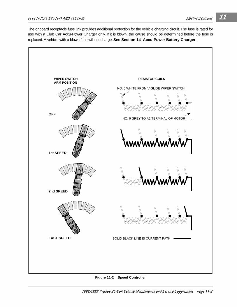
When the control circuit is closed, the vehicle will start in first speed. As the accelerator pedal is depressed,the brush on the wiper switch arm moves across the contacts until the last contact is reached and full speedis attained. The V-Glide wiper switch brush and contacts conduct the motor current through or around eachresistor, thereby controlling the speed (Figure 11-2, Page 11-3) .
The F&R switch changes the direction of vehicle movement by changing the direction of electrical currentthrough the motor, and consequently, the direction the motor turns. By limiting maximum voltage available inREVERSE to one-half that available in FORWARD, maximum vehicle speed in REVERSE is limited to one-half the maximum vehicle speed in FORWARD.
THE CHARGE CIRCUITThe charge circuit consists of the battery charger, charger plug, charger receptacle, onboard fuse link, andthe batteries. The batteries and the battery charger are discussed in separate sections in this manual (Sec-tion 13–Batteries and Section 14–Accu-Power Battery Charger) .
The charger plug and receptacle connection is a critical link between the charger and the vehicle battery cir-cuit. The contacts in the receptacle must grip the plug blades well enough to create enough pressure or dragfor an adequate electrical connection. If little or no drag is felt, the receptacle or plug must be replaced. Ifeither the plug or receptacle is damaged or feels hot when charging, one or both must be replaced. See Sec-tion 14–Accu-Power Battery Charger .
Page 11-2 1998/1999 V-Glide 36-Volt Vehicle Maintenance and Service Supplement
ELECTRICAL SYSTEM AND TESTING Electrical Circuits
11
The onboard receptacle fuse link provides additional protection for the vehicle charging circuit. The fuse is rated foruse with a Club Car Accu-Power Charger only. If it is blown, the cause should be determined before the fuse isreplaced. A vehicle with a blown fuse will not charge. See Section 14–Accu-Power Battery Charger .
Figure 11-2 Speed Controller
NO. 6 WHITE FROM V-GLIDE WIPER SWITCH
NO. 6 GREY TO A2 TERMINAL OF MOTOR
SOLID BLACK LINE IS CURRENT PATH
OFF
1st SPEED
2nd SPEED
LAST SPEED
WIPER SWITCHARM POSITION
RESISTOR COILS
1998/1999 V-Glide 36-Volt Vehicle Maintenance and Service Supplement Page 11-3

ELECTRICAL SYSTEM AND TESTING Electrical Circuits
11
Figure 11-3 Vehicle Wiring Diagram
-
+
+
-
-
-+
+
+
+
-
-
A1S2
A2
S1
1
2
3
46
5
1
1
2
+
-
WHITE
GREEN
14
19
2513
17
BULLETCONNECTOR
RED
RED
BLACK
BLACK
WH
ITE
SPEEDSWITCH
WHITE
18
FORWARD / REVERSESWITCH
REVERSEBUZZER
FUSE AND RECEPTACLE
ORANGE
15BLUE
RED
WHITE
WHITE21
SOLENOID
GREEN
12
GREEN
BLUE
BLACK
WHITE
RED
GREEN
WH
ITE
OR
AN
GE
YE
LLOW
GR
EE
N
BLU
E
BLA
CK
11
9
8
6
5
7
10
23
BROWNPURPLE
GREENRED
1
2
LIMITSWITCH
YELLOW
24
KEYSWITCH
ORANGE
RED
WHITE
2220
16
BLUE
BATTERYBANK
BLACK
GREENWHITE
TYPICAL5 PLACES
26
3
GRAY
BLACK
RESISTORBOARD
4
MOTOR
BROWNPURPLE
GRAY
RED
SOLENOID
SNUBBER
WHITE
BLACKRED
YELLOW
GREEN
WHITE
WHITE
DIODE
Page 11-4 1998/1999 V-Glide 36-Volt Vehicle Maintenance and Service Supplement

ELECTRICAL SYSTEM AND TESTING Troubleshooting
11
TROUBLESHOOTING
V-GLIDE 36-VOLT TROUBLESHOOTING GUIDE
SYMPTOM PROBLEM POSSIBLE CAUSES REFER TO
1. Vehicle will not operate - no solenoid click.
Batteries 1) Battery connections Test Procedure 1, Page 11-7
2) Batteries discharged Test Procedure 1, Page 11-7
Key Switch 1) Loose wires. Test Procedure 2, Page 11-7
2) Failed switch. Test Procedure 2, Page 11-7
F&R Anti-arching limit switch 1) Loose wires Test Procedure 3, Page 11-7
2) Failed Switch Test Procedure 3, Page 11-7
3) Cam is not activating switch Test Procedure 3, Page 11-7
Accelerator 1) Accelerator rod disconnected Accelerator and Brake Pedal, Section 5
Accelerator Pedal Limit Switch
1) Loose wire Test Procedure 4, Page 11-8
2) Disconnected or improperly connected wires.
Test Procedure 4, Page 11-8
3) Failed switch. Test Procedure 4, Page 11-8
Solenoid 1) Loose switch Test Procedures 10 & 11, Pages 11-12 & 11-13
2) Failed coil Test Procedure 5, Page 11-8
2. Vehicle will not operate - solenoid clicks.
F&R Switch 1) Loose wires. Test Procedure 8, Page 11-10
2) Failed contacts Test Procedure 10, Page 11-12
Solenoid 1) Failed contacts Test Procedure 10, Page 11-12
V-Glide Wiper Switch 1) Loose wires or broken wire connections
Test Procedure 12, Page 11-14
2) Brush or contacts are dirty, burned, corroded, shorted, or worn.
Test Procedure 12, see also Electrical Components, Sec-tion 12
3) Improperly wired Figure 11-3, Page 11-4
Motor 1) Loose wires Test Procedure 9, Page 11-11
2) Open circuits Test Procedure 9, see also Motor, Section 15
3) Worn brushes Test Procedure 9, Page 11-11
3. Vehicle skips one or more speeds.
V-Glide Wiper Switch 1) Loose or broken wire connec-tions.
Test Procedure 12, Page 11-14
2) Brush or contacts are dirty, burned, corroded, shorted or worn.
Test Procedure 12, see also Electrical Components, Sec-tion 12.
3) Improperly wired. Figure 11-3, Page 11-4
Resistors 1) Loose or broken resistor. Test Procedure 7, Page 11-10
Troubleshooting Guide continued on next page.
1998/1999 V-Glide 36-Volt Vehicle Maintenance and Service Supplement Page 11-5

ELECTRICAL SYSTEM AND TESTING Troubleshooting
11
V-GLIDE 36-VOLT TROUBLESHOOTING GUIDE
SYMPTOM PROBLEM POSSIBLE CAUSES REFER TO
4. Vehicle operates slowly. V-Glide Wiper Switch 1) Poor wire connections Figure 11-3, Page 11-4
2) Dirty or worn contact points Test Procedure 12, Page 11-14
Batteries 1) Loose terminals or corrosion. Test Procedure 1, see alsoBatteries, Section 13
2) Improperly wired. Figure 11-3, Page 11-4
3) Batteries failed See Batteries, Section 13
4) Batteries not fully charged. See Charger, Section 14
Accelerator Push Rod 1) Accelerator rod is improperlyadjusted.
V-Glide Wiper Switch,Section 12, Components
Motor 1) Loose wire. Test Procedure 9, Page 11-11
2) Worn or misaligned brushes. Motor, Section 15
3) Dirty or rough commutator. Motor, Section 15
Brakes 1) Dragging brakes. Brakes, Section 6, and Accelerator, Section 5
Tires 1) Under-inflated or flat tires. Wheels and Tires, Section 8.
5. Vehicle operates in first speedwhen the F&R switch isplaced in Forward or Reversewith the keyswitch OFF.
Solenoid 1) Solenoid contacts are welded closed.
Test Procedure 10, Page 11-12
6. Vehicle operates in first speed when the F&R switch is placed in Forward or Reverse with keyswitch ON.
Accelerator Pedal Limit Switch
1) V-Glide Wiper Switch is wired wrong.
Accelerator Limit Switch, page 11-2.
2) Accelerator Limit Switch failed in the closed position.
Test Procedure 4, Page 11-8
Accelerator Rod 1) Accelerator Rod is bent or improperly adjusted.
Accelerator and Brake Pedal, Section 5.
V-Glide Wiper Switch 1) Wiper switch brush or accel-erator pedal is stuck.
Accelerator and Brake Pedal, Section 5.
2) Wiper Switch is improperly adjusted.
Accelerator and Brake Pedal, Section 5.
7. Vehicle will operate in Forward but not in Reverse, or will oper-ate in Reverse but not in For-ward.
F&R Anti-arching Limit Switch 1) Improper actuation or faulty switch.
Test Procedure 3, Page 11-7
F&R Switch 1) Dirty or corroded contacts on the F&R switch.
Section 12, Electrical Compo-nents
Battery Wires 1) Improperly wired. Figure 11-3, Page 11-4
8. Vehicle not being fully charged.
Charger connections 1) Loose wires at receptacle, batteries or F&R switch
Accu-Power Charger, Section 14
2) Improper engagement of charger plug and receptacle.
Accu-Power Charger, Section 14
Onboard receptacle fuse link 1) Fuse is blown Accu-Power Charger, Section 14
Charger 1) Incorrect incoming AC volt-age.
Accu-Power Charger, Section 14
2) Charger output is low. Accu-Power Charger, Section 14
3) Charger cord and plugs. Accu-Power Charger, Section 14
Page 11-6 1998/1999 V-Glide 36-Volt Vehicle Maintenance and Service Supplement

ELECTRICAL SYSTEM AND TESTING Circuit Testing
11
CIRCUIT TESTING
Read DANGER and WARNING on page 11-1.
Using the following procedures, the entire electrical system of the V-Glide vehicle can be tested without majordisassembly, however, a multimeter will be necessary to perform these tests.
CONTROL CIRCUIT TEST PROCEDURES
Read DANGER and WARNING on page 11-1.
Test Procedure 1 - Batteries/Voltage Check1. With batteries connected and using a multimeter set to 200 volts DC, place red (+) probe on the positive
post of battery No. 1, and black (-) probe on the negative post of battery No. 6 (Figure 11-4, Page 11-7) . Ifmultimeter does not indicate at least 36 volts with battery fully charged, check for loose battery connectionsor a battery installed in reverse polarity. Refer to Section 13–Batteries for further details on battery testing.
Test Procedure 2 - Key Switch1. With batteries disconnected, place the red (+) probe of a multimeter (set at Ω) on the forward ter-
minal of the F&R switch (Figure 11-5, Page 11-7) and place the black (-) probe on the upper (COM)terminal of the F&R anti-arcing limit switch (Figure 11-5, Page 11-7) . With the key in the OFF posi-tion, the reading should be no continuity.
2. Insert the key and turn the key switch to the ON position. The reading should be continuity.
3. If the reading is incorrect at either of steps one or two, check the wires and terminals. If no problemsare found with the wires or terminals, replace the key switch. See Section 12–Components .
Test Procedure 3 - Forward and Reverse Anti-Arcing Limit Switch
1. With batteries disconnected, place the red (+) probe of the multimeter (set to Ω) on the common termi-nal of the limit switch, and place the black (-) probe on the normally open (NO) terminal. The readingshould be continuity when the limit switch lever is depressed and no continuity when the lever isreleased (Figure 11-6, Page 11-8) .
• IF WIRES ARE REMOVED OR REPLACED MAKE SURE WIRING AND/OR WIRING HARNESS ISPROPERLY ROUTED AND SECURED TO VEHICLE FRAME. FAILURE TO PROPERLY ROUTE ANDSECURE WIRING COULD RESULT IN VEHICLE MALFUNCTION, PROPERTY DAMAGE ORPERSONAL INJURY.
Figure 11-4 Batteries/Voltage Test Figure 11-5 Key Switch Test
CAUTION
- +
2m
20m
200m
2k200
200
200200
20
2
200m
500
20k
200k
2000k
Ω
Ω
1000OFF
WAVETEK 5XLV
V
V
A
! !COM 200nA
MAX1000 ---
750VFUSED
1
2
3
46
5
BATTERYBANK FOR
V-GLIDE 36 VOLTVEHICLE
- +
2m
20m
200m
2k200
200
200200
20
2
200m
500
20k
200k
2000k
Ω
Ω
1000OFF
WAVETEK 5XLV
V
V
A
! !COM 200nA
MAX1000 ---
750VFUSED
RED WIRE
BLUE WIRE
1998/1999 V-Glide 36-Volt Vehicle Maintenance and Service Supplement Page 11-7

ELECTRICAL SYSTEM AND TESTING Circuit Testing
11
Test Procedure 3 - F&R Anti-Arching Limit Switch, Continued:
2. If the reading is incorrect at either lever position, replace switch. If readings are correct, check thewires, terminals and cam actuator on the F&R switch rotor. If no problems are found, the problem is notin the switch. See Section 12–Components .
Test Procedure 4 - Accelerator Pedal Limit Switch1. With batteries disconnected, place the red (+) probe of the multimeter (set to 200 Ω) on the terminal of
the green wire at its connection on the activating coil post of the solenoid, and place the black (-) probeon the negative (-) post of battery number 6 (Figure 11-7, Page 11-8) . With the accelerator pedal fullyup (not depressed), the reading should be no continuity.
2. Depress the accelerator pedal. The reading should be continuity.
3. If either reading is incorrect, remove the V-Glide wiper switch housing cover and check for proper acti-vation of the limit switch by the wiper arm.
4. Also make sure the 18 gauge green wire is connected to the normally closed (NC) terminal of the limitswitch, and the 18 gauge black wire is connected to the common (COM) terminal. There should be nowire attached to the normally open (NO) terminal.
Test Procedure 5 - Solenoid Activating Coil
1. With batteries disconnected, place the red probe (+) of the multimeter (set to 200 Ω) on one of thesmall activating coil posts of the solenoid and place the black (-) probe on the other small post. Thereshould be a reading of 55-60 ohms (Figure 11-8, Page 11-8) .
2. If the reading is incorrect, replace the solenoid.
Figure 11-6 F&R Anti-arcing Limit Switch Test Figure 11-7 Accelerator Pedal Limit Switch Test
Figure 11-8 Solenoid Activating Coil Test
- +
2m
20m
200m
2k200
200
200200
20
2
200m
500
20k
200k
2000k
Ω
Ω
1000OFF
WAVETEK 5XLV
V
V
A
! !COM 200nA
MAX1000 ---
750VFUSED
YELLOW WIRE
BLUE WIRE
ANTI-ARCING LIMITSWITCH
- +
2m
20m
200m
2k200
200
200200
20
2
200m
500
20k
200k
2000k
Ω
Ω
1000OFF
WAVETEK 5XLV
V
V
A
! !COM 200nA
MAX1000 ---
750VFUSED
1
2
3
46
5
BATTERYBANK FOR
V-GLIDE 36 VOLTVEHICLE
SOLENOID
- +
2m
20m
200m
2k200
200
200200
20
2
200m
500
20k
200k
2000k
Ω
Ω
1000OFF
WAVETEK 5XLV
V
V
A
! !COM 200nA
MAX1000 ---
750VFUSED
SOLENOID
Page 11-8 1998/1999 V-Glide 36-Volt Vehicle Maintenance and Service Supplement

ELECTRICAL SYSTEM AND TESTING Circuit Testing
11
Test Procedure 6 - Reverse Buzzer1. Disconnect the batteries, negative cable first (Figure 11-1, Page 11-1) .
2. Remove the center dash:
2.1. Remove the plastic cap covering the screw on each side of the center dash. Loosen (but do notremove) the screws.
2.2. Insert a flat blade screwdriver at top center of the dash between the dash and the cowl brace.Gently pry the center dash out slightly from under the edge of the cowl brace.
2.3. Pull dash out approximately 1 in. from the frame and then bend the top right corner of the dashpanel inward while pulling the top of the panel out and down. See following NOTE.
3. Slide center dash panel up steering column by snapping the top out and then rotating the panel out and up.
4. Disconnect the 18 gauge white wire at the reverse buzzer. Place the red (+) probe of a multimeter (setto 200 Ω) on the large post of the solenoid (with the 6 gauge and the 18 gauge white wires attached),and place the black (-) probe on the terminal end of the 18 gauge white wire at the reverse buzzer. Thereading should be continuity. If it is not, replace the 18 gauge white wire (Figure 11-9, Page 11-9) .
5. Disconnect the 18 gauge orange wire at the reverse buzzer. Place the black (-) probe of a multimeter(set to Ω) on the receptacle fuse assembly at the 10 gauge red wire and 18 gauge orange wire connec-tion, and place the red (+) probe on the terminal end of the 18 gauge orange wire at the reverse buzzer.The multimeter should indicate continuity. If not, replace the 18 gauge orange wire (Figure 11-10,Page 11-9).
6. If there is continuity in both wires, but the buzzer will not sound, replace the buzzer.
7. Reconnect the batteries, positive cable first. Tighten terminal hardware to 110 in.lb (12.4 N-m). Coatterminals with Battery Protector Spray (Club Car Part No. 1014395).
• BENDING THE TOP RIGHT CORNER OF THE CENTER DASH INWARD DURING REMOVALWILL PREVENT THE CONTACTS ON THE BACK OF THE KEY SWITCH FROM TOUCHING THEMETAL FRAME AROUND THE DASH.
Figure 11-9 Reverse Buzzer Test - White Wire Figure 11-10 Reverse Buzzer Test - Orange Wire
NOTE
- +
2m
20m
200m
2k200
200
200200
20
2
200m
500
20k
200k
2000k
Ω
Ω
1000OFF
WAVETEK 5XLV
V
V
A
! !COM 200nA
MAX1000 ---
750VFUSED
SOLENOIDREVERSE BUZZER
18 GAUGE WHITE WIRE
18 GAUGE ORANGE WIRE
- +
2m
20m
200m
2k200
200
200200
20
2
200m
500
20k
200k
2000k
Ω
Ω
1000OFF
WAVETEK 5XLV
V
V
A
! !COM 200nA
MAX1000 ---
750VFUSED
RECEPTACLE
REVERSE BUZZER
18 GAUGE WHITE WIRE
18 GAUGE ORANGE WIRE
1998/1999 V-Glide 36-Volt Vehicle Maintenance and Service Supplement Page 11-9

ELECTRICAL SYSTEM AND TESTING Circuit Testing
11
POWER CIRCUIT TEST PROCEDURES
Read DANGER and WARNING on page 11-1.
Test Procedure 7 - Resistors
1. Inspect the resistors for loose connections, damaged coils or wiring, or problems of any kind. 2. If there are no problems, place the red (+) probe of the multimeter (set to 200 Ω) on the first resistor
connection, and place the black (-) probe on the last resistor connection. The reading should be conti-nuity or approximately .9 ohms (Figure 11-11, Page 11-10) .
3. If the reading is incorrect, check the resistors again for loose connections or damage. Replace anydamaged parts.
Test Procedure 8 - Forward and Reverse (F&R) Switch
1. Disconnect the batteries and use a multimeter (set to 200 Ω) to test the F&R switch in both directions:
1.1. With the F&R switch in the FORWARD position, place the red (+) probe on the common terminal lugof the switch (with brown wire attached), and place the black (-) probe on the movable contact (withthe purple wire attached) on the forward and reverse rotor (Figure 11-12, Page 11-11) . The readingshould be continuity.
1.2. With the F&R switch in FORWARD, place the red (+) probe on the forward terminal lug (with the sixgauge red wire attached) of the F&R switch, and place the black (-) probe on the movable contact(with the white wire attached) on the forward and reverse rotor (Figure 11-13, Page 11-11) . Thereading should be continuity.
• DO NOT TOUCH HOT RESISTORS! HOT RESISTORS CAN CAUSE SEVERE BURNS.
Figure 11-11 Resistor Test
• IF YOUR VEHICLE HAS A SERIAL NUMBER BETWEEN A9501-417833 AND A9926-773264,VISUALLY INSPECT THE F&R SWITCH TO MAKE SURE IT IS THE SAME DESIGN AS SHOWN INFIGURE 11-16, PAGE 11-12. IF IT IS NOT, CONTACT YOUR LOCAL DISTRIBUTOR/DEALER ORA CLUB CAR TECHNICAL SERVICE REPRESENTATIVE FOR INFORMATION REGARDING AREPLACEMENT KIT FOR THIS COMPONENT.
WARNING
- +
2m
20m
200m
2k200
200
200200
20
2
200m
500
20k
200k
2000k
Ω
Ω
1000OFF
WAVETEK 5XLV
V
V
A
! !COM 200nA
MAX1000 ---
750VFUSED
FRONT OF CAR
RESISTOR
NOTE
Page 11-10 1998/1999 V-Glide 36-Volt Vehicle Maintenance and Service Supplement

ELECTRICAL SYSTEM AND TESTING Circuit Testing
11
1.3. With the F&R switch in the REVERSE position, place the red (+) probe on the common termi-nal lug (with brown wire attached) of the F&R switch, and place the black (-) probe on themovable contact (with the white wire attached) on the forward and reverse rotor (Figure 11-14, Page 11-11). The reading should be continuity.
1.4. With the Forward/Reverse handle in the REVERSE position, place the red (+) probe on thereverse terminal lug of the F&R switch (with green wire attached), and place the black (-) probe onthe movable contact (with the purple wire attached) on forward and reverse rotor (Figure 11-15,Page 11-11). Reading should be continuity.
2. If the reading is incorrect at any position in Step 1, refer to Section 12–Components .
Test Procedure 9 - Motor1. Disconnect batteries and use a multimeter (set to 200 Ω) to test motor armature and motor stator as follows:
1.1. To test the motor armature place the Forward/Reverse handle in the NEUTRAL position, placethe red (+) probe on the terminal (with the heavy purple wire attached) on the forward and reverserotor, and place the black (-) probe on the last resistor coil connection (black and gray wires). Thereading should be continuity (Figure 11-17, Page 11-12) .
Figure 11-12 F&R Switch Test - Step 1.1 Figure 11-13 F&R Switch Test - Step 1.2
Figure 11-14 F&R Switch Test - Step 1.3 Figure 11-15 F&R Switch Test - Step 1.4
- +
2m
20m
200m
2k200
200
200200
20
2
200m
500
20k
200k
2000k
Ω
Ω
1000OFF
WAVETEK 5XLV
V
V
A
! !COM 200nA
MAX1000 ---
750VFUSED
FORWARD/REVERSESWITCH
- +
2m
20m
200m
2k200
200
200200
20
2
200m
500
20k
200k
2000k
Ω
Ω
1000OFF
WAVETEK 5XLV
V
V
A
! !COM 200nA
MAX1000 ---
750VFUSED
FORWARD/REVERSESWITCH
- +
2m
20m
200m
2k200
200
200200
20
2
200m
500
20k
200k
2000k
Ω
Ω
1000OFF
WAVETEK 5XLV
V
V
A
! !COM 200nA
MAX1000 ---
750VFUSED
FORWARD/REVERSESWITCH
- +
2m
20m
200m
2k200
200
200200
20
2
200m
500
20k
200k
2000k
Ω
Ω
1000OFF
WAVETEK 5XLV
V
V
A
! !COM 200nA
MAX1000 ---
750VFUSED
FORWARD/REVERSESWITCH
1998/1999 V-Glide 36-Volt Vehicle Maintenance and Service Supplement Page 11-11
ELECTRICAL SYSTEM AND TESTING Circuit Testing
11
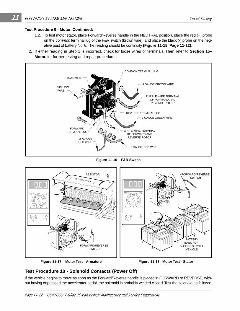
Test Procedure 9 - Motor, Continued:1.2. To test motor stator, place Forward/Reverse handle in the NEUTRAL position, place the red (+) probe
on the common terminal lug of the F&R switch (brown wire), and place the black (-) probe on the neg-ative post of battery No. 6. The reading should be continuity (Figure 11-18, Page 11-12) .
2. If either reading in Step 1 is incorrect, check for loose wires or terminals. Then refer to Section 15–Motor, for further testing and repair procedures.
Test Procedure 10 - Solenoid Contacts (Power Off)If the vehicle begins to move as soon as the Forward/Reverse handle is placed in FORWARD or REVERSE, with-out having depressed the accelerator pedal, the solenoid is probably welded closed. Test the solenoid as follows:
Figure 11-16 F&R Switch
Figure 11-17 Motor Test - Armature Figure 11-18 Motor Test - Stator
6 GAUGE GREEN WIRE
6 GAUGE RED WIRE
18 GAUGE RED WIRE
6 GAUGE BROWN WIREYELLOW WIRE
BLUE WIRE
COMMON TERMINAL LUG
FORWARDTERMINAL LUG
REVERSE TERMINAL LUG
WHITE WIRE TERMINALOF FORWARD ANDREVERSE ROTOR
PURPLE WIRE TERMINALOF FORWARD ANDREVERSE ROTOR
- +
2m
20m
200m
2k200
200
200200
20
2
200m
500
20k
200k
2000k
Ω
Ω
1000OFF
WAVETEK 5XLV
V
V
A
! !COM 200nA
MAX1000 ---
750VFUSED
FRONT OF CAR
FORWARD/REVERSESWITCH
RESISTOR
- +
2m
20m
200m
2k200
200
200200
20
2
200m
500
20k
200k
2000k
Ω
Ω
1000OFF
WAVETEK 5XLV
V
V
A
! !COM 200nA
MAX1000 ---
750VFUSED
1
23
46
5
FORWARD/REVERSESWITCH
BATTERYBANK FOR
V-GLIDE 36 VOLTVEHICLE
Page 11-12 1998/1999 V-Glide 36-Volt Vehicle Maintenance and Service Supplement

ELECTRICAL SYSTEM AND TESTING Circuit Testing
11
1. Heed all WARNING statements. Failure to do so could result in unexpected vehicle acceleration.
2. Place the red (+) probe of a multimeter (set at Ω) on one of the large terminal posts on the solenoid, and placethe black (-) probe on the other large terminal post on the solenoid. The reading should be no continuity (Fig-ure 11-19, Page 11-13) .
3. If the reading is incorrect, replace the solenoid and snubber. See Section 12–Components.
Test Procedure 11 - Solenoid Contacts (Power On)
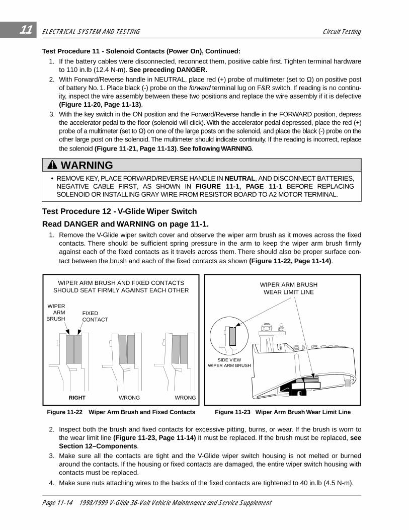
• BEFORE CONNECTING THE BATTERIES, DISCONNECT THE GRAY WIRE FROM THE RESISTORBOARD TO THE A2 MOTOR TERMINAL AND REMOVE THE WIRE FROM THE VEHICLE. THENRAISE THE REAR END OF THE VEHICLE UNTIL THE REAR WHEELS ARE OFF THE FLOOR (SEEWARNING ON PAGE 11-1). WITH THE GRAY WIRE REMOVED, THE SOLENOID CAN BE ACTIVATEDWITHOUT SUPPLYING POWER TO THE REAR WHEELS. FAILURE TO DISCONNECT THE GRAYWIRE CAN CAUSE THE VEHICLE TO START ABRUPTLY.
Figure 11-19 Solenoid Contacts - Power Off
Figure 11-20 Solenoid Contacts - Power On, Step 1 Figure 11-21 Solenoid Contacts - Power On, Step 2
DANGER
- +
2m
20m
200m
2k200
200
200200
20
2
200m
500
20k
200k
2000k
Ω
Ω
1000OFF
WAVETEK 5XLV
V
V
A
! !COM 200nA
MAX1000 ---
750VFUSED
SOLENOID
- +
2m
20m
200m
2k200
200
200200
20
2
200m
500
20k
200k
2000k
Ω
Ω
1000OFF
WAVETEK 5XLV
V
V
A
! !COM 200nA
MAX1000 ---
750VFUSED
1
23
46
5
FORWARD/REVERSESWITCH
BATTERYBANK FOR
V-GLIDE 36 VOLTVEHICLE
- +
2m
20m
200m
2k200
200
200200
20
2
200m
500
20k
200k
2000k
Ω
Ω
1000OFF
WAVETEK 5XLV
V
V
A
! !COM 200nA
MAX1000 ---
750VFUSED
SOLENOID
1998/1999 V-Glide 36-Volt Vehicle Maintenance and Service Supplement Page 11-13
ELECTRICAL SYSTEM AND TESTING Circuit Testing11
Test Procedure 11 - Solenoid Contacts (Power On), Continued:
1. If the battery cables were disconnected, reconnect them, positive cable first. Tighten terminal hardwareto 110 in.lb (12.4 N-m). See preceding DANGER.
2. With Forward/Reverse handle in NEUTRAL, place red (+) probe of multimeter (set to Ω) on positive postof battery No. 1. Place black (-) probe on the forward terminal lug on F&R switch. If reading is no continu-ity, inspect the wire assembly between these two positions and replace the wire assembly if it is defective(Figure 11-20, Page 11-13) .
3. With the key switch in the ON position and the Forward/Reverse handle in the FORWARD position, depressthe accelerator pedal to the floor (solenoid will click). With the accelerator pedal depressed, place the red (+)probe of a multimeter (set to Ω) on one of the large posts on the solenoid, and place the black (-) probe on theother large post on the solenoid. The multimeter should indicate continuity. If the reading is incorrect, replacethe solenoid (Figure 11-21, Page 11-13) . See following WARNING .
Test Procedure 12 - V-Glide Wiper Switch
Read DANGER and WARNING on page 11-1.1. Remove the V-Glide wiper switch cover and observe the wiper arm brush as it moves across the fixed
contacts. There should be sufficient spring pressure in the arm to keep the wiper arm brush firmlyagainst each of the fixed contacts as it travels across them. There should also be proper surface con-tact between the brush and each of the fixed contacts as shown (Figure 11-22, Page 11-14) .
2. Inspect both the brush and fixed contacts for excessive pitting, burns, or wear. If the brush is worn tothe wear limit line (Figure 11-23, Page 11-14) it must be replaced. If the brush must be replaced, seeSection 12–Components .
3. Make sure all the contacts are tight and the V-Glide wiper switch housing is not melted or burnedaround the contacts. If the housing or fixed contacts are damaged, the entire wiper switch housing withcontacts must be replaced.
4. Make sure nuts attaching wires to the backs of the fixed contacts are tightened to 40 in.lb (4.5 N-m).
• REMOVE KEY, PLACE FORWARD/REVERSE HANDLE IN NEUTRAL, AND DISCONNECT BATTERIES,NEGATIVE CABLE FIRST, AS SHOWN IN FIGURE 11-1, PAGE 11-1 BEFORE REPLACINGSOLENOID OR INSTALLING GRAY WIRE FROM RESISTOR BOARD TO A2 MOTOR TERMINAL.
Figure 11-22 Wiper Arm Brush and Fixed Contacts Figure 11-23 Wiper Arm Brush Wear Limit Line
WARNING
RIGHT WRONG WRONG
WIPER ARM BRUSH AND FIXED CONTACTSSHOULD SEAT FIRMLY AGAINST EACH OTHER
WIPERARM
BRUSHFIXED CONTACT
WIPER ARM BRUSHWEAR LIMIT LINE
SIDE VIEWWIPER ARM BRUSH
Page 11-14 1998/1999 V-Glide 36-Volt Vehicle Maintenance and Service Supplement

12
SECTION 12–ELECTRICAL COMPONENTS
• BATTERY - EXPLOSIVE GASES! DO NOT SMOKE. KEEP SPARKS AND FLAMES AWAY.VENTILATE WHEN CHARGING OR USING IN AN ENCLOSED SPACE. ALWAYS WEAR FULLFACE SHIELD WHEN WORKING ON OR NEAR BATTERIES.
• USE EXTREME CAUTION WHEN USING TOOLS, WIRES, OR METAL OBJECTS NEARBATTERIES! A SHORT CIRCUIT AND (OR) SPARK COULD CAUSE AN EXPLOSION.
• BATTERY - POISON! CONTAINS ACID! CAUSES SEVERE BURNS. AVOID CONTACT WITHSKIN, EYES, OR CLOTHING. ANTIDOTES:
- EXTERNAL: FLUSH WITH WATER. CALL A PHYSICIAN IMMEDIATELY.
- INTERNAL: DRINK LARGE QUANTITIES OF MILK OR WATER. FOLLOW WITH MILK OFMAGNESIA OR VEGETABLE OIL. CALL A PHYSICIAN IMMEDIATELY.
- EYES: FLUSH WITH WATER FOR FIFTEEN MINUTES. CALL PHYSICIAN IMMEDIATELY.
• ONLY TRAINED TECHNICIANS SHOULD REPAIR OR SERVICE THIS VEHICLE. ANYONE DOINGEVEN SIMPLE REPAIRS OR SERVICE SHOULD HAVE KNOWLEDGE AND EXPERIENCE INGENERAL MECHANICAL AND ELECTRICAL REPAIR. FOLLOW ALL PROCEDURES EXACTLYAND HEED ALL WARNINGS STATED IN THIS MANUAL.
• ALWAYS WEAR SAFETY GLASSES OR APPROVED EYE PROTECTION WHILE SERVICINGVEHICLE. WEAR A FULL FACE SHIELD WHEN WORKING WITH BATTERIES.
• DO NOT WEAR LOOSE CLOTHING. REMOVE JEWELRY SUCH AS RINGS, WATCHES, CHAINS,ETC. BEFORE SERVICING VEHICLE.
• ALWAYS USE INSULATED TOOLS WHEN WORKING NEAR BATTERIES OR ELECTRICALCONNECTIONS. WHEN BATTERIES ARE CONNECTED, USE EXTREME CAUTION TO AVOIDSHORT CIRCUITS IN COMPONENTS OR WIRING.
• TO AVOID UNINTENTIONALLY STARTING THE VEHICLE, DISCONNECT BATTERIES, NEGATIVECABLE FIRST, AS SHOWN IN FIGURE 12-1, PAGE 12-1 WHEN PERFORMING TESTS THAT DONOT REQUIRE THE ELECTRICAL SYSTEM TO BE ENERGIZED.
Figure 12-1 V-Glide Battery Configuration
DANGER
WARNING
1
2
3
46
5
FRONTOF VEHICLE
DISCONNECT THESE BATTERY CABLES BEFORE
WORKING ON VEHICLE
1998/1999 V-Glide 36-Volt Vehicle Maintenance and Service Supplement Page 12-1

ELECTRICAL COMPONENTS Key Switch
12
KEY SWITCH
Read DANGER and WARNING on page 12-1.The key switch is mounted to the right of the steering column on the center dash panel.
Testing the Key Switch
See Section 11, Test Procedure 2, Page 11-7.
Key Switch Removal1. Disconnect the batteries, negative cable first (Figure 12-1, Page 12-1) .
2. Remove the center dash:
2.1. Remove the plastic cap covering the screw on each side of the center dash. Loosen (but do notremove) the screws.
2.2. Insert a flat blade screwdriver at top center of the dash between the dash and the cowl brace.Gently pry the center dash out slightly from under the edge of the cowl brace.
2.3. Pull dash out approximately 1 in. from the frame and then bend the top right corner of the dashpanel inward while pulling the top of the panel out and down. See following NOTE.
3. Slide center dash panel up the steering column by snapping the top out and then rotating the panel outand up.
4. Disconnect the wires from the key switch. Do not allow the wires to touch.
5. From the back of the dash panel, push down on the retaining tabs surrounding the key switch andremove the key switch cap (8). Hold the key switch and remove the switch retaining nut (6) from the out-side of the dash panel (Figure 12-2, Page 12-3) .
Key Switch Installation1. Position the key switch in the center dash and install the switch retaining nut. Press the plastic cap into
place on the outside of the center dash (Figure 12-2, Page 12-3) .
2. Connect the wires to the key switch terminals (see Section 11, Figure 11-3, Vehicle Wiring Diagram,Page 11-4) and then coat the terminals with Battery Protector Spray (Club Car Part No. 1014305).
3. Install the center dash by reversing the removal procedure. Make sure the key switch terminals cannot touchthe frame and that the panel is properly seated and snapped into place.
4. Reconnect battery cables, positive cable first, and tighten terminal hardware to 110 in.lb (12.4 N-m).
FORWARD/REVERSE (F&R) ANTI-ARCING LIMIT SWITCH
Read DANGER and WARNING on page 12-1.The F&R Anti-arcing Limit switch is located on the F&R switch and is activated by a cam on the F&R switch rotor.
Testing the Anti-arcing Limit SwitchSee Section 11, Test Procedure 3, Page 11-7.
• BENDING THE TOP RIGHT CORNER OF THE CENTER DASH INWARD DURING REMOVALWILL PREVENT THE CONTACTS ON THE BACK OF THE KEY SWITCH FROM TOUCHING THEMETAL FRAME AROUND THE DASH.
NOTE
Page 12-2 1998/1999 V-Glide 36-Volt Vehicle Maintenance and Service Supplement

ELECTRICAL COMPONENTS Accelerator Pedal Limit Switch
12
Anti-arcing Limit Switch Removal1. Remove the nuts, lock washers, and screws attaching the anti-arcing limit switch to the F&R switch
(Figure 12-3, Page 12-3) .
Anti-arcing Limit Switch Installation1. Position the anti-arcing limit switch (2) on the F&R switch housing and install the screws, lock washers,
and nuts. Tighten the screws to 5 in.lb (0.6 N-m) (Figure 12-3, Page 12-3) .
2. Connect the blue wire (9) to the common (COM) terminal (6) and the yellow wire (8) to the normally open(NO) terminal (7) (Figure 12-3, Page 12-3) .
3. After installation, make sure the switch makes an audible click (makes and breaks contact) when theforward and reverse rotor is turned. If it does not click, inspect the forward and reverse rotor and limitswitch for damage.
ACCELERATOR PEDAL LIMIT SWITCH
Read DANGER and WARNING on page 12-1.Testing the Accelerator Pedal Limit SwitchSee Section 11, Test Procedure 4, Page 11-8.
Accelerator Pedal Limit Switch Removal1. Disconnect battery cables, negative cable first. Remove No. 5 and No. 6 batteries from vehicle (Figure 12-1,
Page 12-1).2. Remove the cover (10) from the V-Glide wiper switch housing (1) (Figure 12-8, Page 12-10) .
3. Disconnect the accelerator rod from the ball stud (5) on the wiper switch (Figure 12-8, Page 12-10) .
4. Remove and retain the screws (19), lock washers (16), and nuts (22) attaching the limit switch (20) tothe wiper switch (Figure 12-8, Page 12-10) .
5. Disconnect the green (35) and black wires (36) from the limit switch (Figure 12-8, Page 12-10) .
Figure 12-2 Key Switch Figure 12-3 F&R Anti-arcing Limit Switch
4
5
6
8
9
7
FRONT PANEL
2
3 TYPICAL 2PLACES
45
TYPICAL 2PLACES
1
7
6
9
8
1998/1999 V-Glide 36-Volt Vehicle Maintenance and Service Supplement Page 12-3

ELECTRICAL COMPONENTS Reverse Buzzer
12
Accelerator Pedal Limit Switch Installation1. Position accelerator pedal limit switch (20) on V-Glide wiper switch body and install mounting screws
(19), lock washers (16), and nuts (22). Tighten screws to 5 in.lb (0.6 N-m) (Figure 12-8, Page 12-10) .
2. Connect the accelerator rod ball joint to the ball stud (5) on the wiper switch (Figure 12-8, Page 12-10) .
3. Connect the green wire (35) to the normally closed (NC) terminal and the black wire (36) to the com-mon (COM) terminal of the limit switch. The normally open (NO) terminal should have no wire attachedto it (Figure 12-8, Page 12-10) .
4. Install cover (10) on V-Glide wiper switch (make sure all three tabs snap into place) (Figure 12-8, Page 12-10) .
5. Install the No. 5 and No. 6 batteries and connect battery cables, positive cable first. Tighten terminal hardwareto 110 in.lb (12.4 N-m) (Figure 12-1, Page 12-1) .
REVERSE BUZZER
Read DANGER and WARNING on page 12-1.
Testing the Reverse BuzzerSee Section 11,Test Procedure 6, Page 11-9.
Reverse Buzzer Removal1. Disconnect the batteries, negative cable first, (Figure 12-1, Page 12-1) and remove the center dash.
See Remove Center Dash, Page 12-2.2. Remove the orange and white wires from the buzzer terminals. See Section 11, Figure 11-3, Vehicle
Wiring Diagram, Page 11-4. Remove the screws attaching the buzzer to the center dash.
Reverse Buzzer Installation1. Install reverse buzzer and center dash by reversing removal procedures. Tighten screws to 4 in.lb (0.45 N-m).
2. Reconnect battery cables, positive cable first. Tighten battery hardware to 110 in.lb (12.4 N-m).
THE SOLENOID
Read DANGER and WARNING on page 12-1.The solenoid is mounted in front of the No. 3 and No. 4 batteries (Figure 12-1, Page 12-1) . It has two sets ofterminal posts. The two large terminal posts are power contact terminals and the two small posts are activat-ing coil terminals.
Testing the SolenoidSee Section 11, Test Procedure 5, Page 11-8, and Test Procedures 10 and 11, Page 11-12.
Solenoid Removal1. Disconnect battery cables, negative cable first (Figure 12-1, Page 12-1) . Disconnect wires from solenoid.
2. Remove the two thread rolling screws attaching the solenoid to the vehicle.
Solenoid Installation1. Position the solenoid with the small posts toward the front of the vehicle and install one of the mounting
screws through the driver side hole on the solenoid base and into the corresponding hole in the mountingplate (Figure 12-4, Page 12-5). Tighten screw to 50 in.lb (7.3 N-m).
2. Install passenger side screw and tighten to 50 in.lb (5.6 N-m) (Figure 12-4, Page 12-5).3. Install diode assembly onto small solenoid posts. Make sure the direction of the diode is correct. The red
insulated terminal of the diode assembly should be installed on the same post to which the 18 gauge yellowwire is attached, and the clear insulated terminal of the diode assembly should be installed on the same postto which the 18 gauge green wire is attached (Figure 12-5, Page 12-5) .
Page 12-4 1998/1999 V-Glide 36-Volt Vehicle Maintenance and Service Supplement

ELECTRICAL COMPONENTS The Solenoid
12
4. Attach snubber assembly to frame on either the passenger or the driver side of the solenoid using awire tie and cable tie mounting base (Figure 12-4, Page 12-5) .
5. Attach wiring to solenoid. Connect black wire from snubber to the same large solenoid post to which the6 gauge white wire (from the speed switch) is attached. Connect red wire from the snubber to the samelarge post to which the 18 gauge and 6 gauge white wires are attached. See following CAUTION .
6. Using a low profile wrench to hold the inner nuts on the solenoid posts in place, tighten the outer nutsof the large posts to 75 in.lb (8.5 N-m). Tighten the outer nuts of the small solenoid posts to 18 in.lb (2N-m) (Figure 12-5, Page 12-5) . See following WARNING.
• DO NOT DAMAGE SNUBBER WHEN MOUNTING SOLENOID.• INSTALL BOTH MOUNTING SCREWS. FAILURE TO INSTALL BOTH SCREWS CAN RESULT IN
SOLENOID AND ELECTRICAL SYSTEM DAMAGE AND FAILURE.
Figure 12-4 Mount Solenoid Figure 12-5 Connect Solenoid Wires
• MAKE SURE THE WIRES ARE ROUTED SO THE WIRE FROM THE FORWARD AND REVERSEROTOR DOES NOT PULL ON OTHER WIRES AS THE FORWARD/REVERSE HANDLE IS SHIFTED.
• FAILURE TO HOLD THE INNER NUTS ON THE SOLENOID POSTS WHILE TIGHTENING THEOUTER NUTS OR NOT TIGHTENING THE OUTER NUTS TO THE PROPER SPECIFICATIONSCAN RESULT IN SOLENOID DAMAGE AND FAILURE.
WARNING
FRONTOF VEHICLE
SNUBBER MOUNTED ON THE DRIVER SIDE OF THE SOLENOID
WIRE TIE
CABLE TIE MOUNTING BASE
18 GAUGE WHITE WIRE
RED WIRE FROM SNUBBER
BLACK WIRE FROM SNUBBER
6 GAUGE WHITE WIREFROM SPEED SWITCH
6 GAUGE WHITE WIREFROM F&R SWITCH
18 GAUGE YELLOW WIRE
18 GAUGE GREEN WIRE
TORQUE WRENCH
OPEN-END WRENCH
DIODE
RED TERMINAL
CAUTION
WARNING
1998/1999 V-Glide 36-Volt Vehicle Maintenance and Service Supplement Page 12-5

ELECTRICAL COMPONENTS Resistors
12
Solenoid SnubberThe solenoid snubber circuit is an arc suppression device that reduces the amount of sparking created asthe solenoid contacts open while under a current load. This device minimizes pitting of the contacts andincreases solenoid life. There is no method for troubleshooting the snubber circuit. If the solenoid fails, thesnubber should also be replaced.
RESISTORS
Read DANGER and WARNING on page 12-1.The resistors are attached to the resistor mounting board which is located behind the batteries.
Testing the ResistorsSee Section 11, Test Procedure 7, Page 11-10.
Resistor Removal1. Disconnect battery cables, negative cable first (Figure 12-1, Page 12-1) . Loosen (do not remove) the
nuts (1) that secure the resistors (R1 - R5) to the mounting board and then slide the resistors out fromunder the washers (3) (Figure 12-6, Page 12-7) .
Resistor Installation1. Position resistor ends under washers (3) and tighten nuts to 95 in.lb (11 N-m) (Figure 12-6, Page 12-7) .
Reconnect battery cables, positive cable first. Tighten terminal hardware to 110 in.lb (12.4 N-m). See fol-lowing CAUTION and NOTE .
V-GLIDE WIPER SWITCH
Read DANGER and WARNING on page 12-1.The V-Glide wiper switch is located in the battery compartment next to battery No. 6 (Figure 12-8, Page 12-10). The wiper switch arm adjustment should be checked if the brush on the V-Glide wiper switch is replaced.The pedal group adjustments (see Section 5–Accelerator and Brake Pedal) should to be checked if any ofthe pedal group or the accelerator rod has been adjusted, removed, or replaced. See following WARNING.
• BE SURE THE MOTOR WIRES ARE SECURED IN WIRE TIES SO THEY CANNOT COME INTOCONTACT WITH THE RESISTORS.
• BE SURE RESISTORS ARE NO CLOSER THAN ONE INCH TO RESISTOR SHIELD. IFRESISTORS ARE CLOSER THAN ONE INCH TO RESISTOR SHIELD, ADJUST THE RESISTORS.
• IF A 3-1/2 HORSEPOWER MOTOR IS BEING USED IN CONJUNCTION WITH A V-GLIDE WIPERSWITCH, THE FOURTH AND FIFTH SPEED RESISTOR COILS MUST BE REPLACED WITH NEWCOILS (CLUB CAR PART NOS. 1014654 AND 1014655).
• MAKE SURE RESISTOR COILS DO NOT TOUCH EACH OTHER. THE VEHICLE WILL NOT RUNPROPERLY IF ANY COILS ARE TOUCHING.
• MAKE SURE THE RESISTOR COILS ARE INSTALLED IN THE PROPER ORDER (FIGURE 12-6,PAGE 12-7). RESISTOR 1 HAS THE SMALLEST DIAMETER WIRE AND THE GREATESTNUMBER OF COILS. RESISTOR 5 HAS THE LARGEST DIAMETER WIRE AND THE SMALLESTNUMBER OF COILS.
CAUTION
NOTE
Page 12-6 1998/1999 V-Glide 36-Volt Vehicle Maintenance and Service Supplement

ELECTRICAL COMPONENTS V-Glide Wiper Switch
12
The V-Glide wiper switch assembly should be inspected on a monthly basis for cracks or damage and to ver-ify it is securely attached to the vehicle frame.
• BE SURE THE V-GLIDE WIPER SWITCH ARM SHAFT ROTATES FREELY IN THE HOUSING. IFTHE WIPER SWITCH ARM SHAFT BINDS OR STICKS, IT MUST BE REPLACED.
• MAKE SURE THE V-GLIDE WIPER SWITCH ASSEMBLY IS SECURELY FASTENED TO THEFRAME AFTER INSTALLATION.
Figure 12-6 Mounting Board and Resistors
• INSPECT THE V-GLIDE WIPER SWITCH HOUSING FOR CRACKS OR DAMAGE BEFOREINSTALLATION. IF THE HOUSING IS CRACKED OR DAMAGED, THE ENTIRE HOUSING WITHFIXED CONTACTS MUST BE REPLACED.
• WHEN WASHING THE VEHICLE, DO NOT DIRECT THE WATER STREAM AT THE WIPER SWITCH.• DO NOT OPERATE THE VEHICLE WITHOUT THE V-GLIDE WIPER SWITCH COVER IN PLACE.
WARNING
FRONT OF CAR
1
3
2
1
2
6
12
4
7 89
1011
5
12
13
TYPICAL6 PLACES
TYPICAL6 PLACES
TYPICAL2 PLACES
TYPICAL2 PLACES
TYPICAL6 PLACES
FRONT OF CAR
1
3
2
1
2
6
12
4
7 89
1011
5
12
13
TYPICAL6 PLACES
TYPICAL6 PLACES
TYPICAL2 PLACES
TYPICAL2 PLACES
TYPICAL6 PLACES
CAUTION
1998/1999 V-Glide 36-Volt Vehicle Maintenance and Service Supplement Page 12-7

ELECTRICAL COMPONENTS V-Glide Wiper Switch
12
V-GLIDE WIPER SWITCH ARM ADJUSTMENTThe contact surfaces on the wiper switch arm brush and the fixed contacts must be parallel to ensure effi-cient operation of the V-Glide wiper switch (Figure 12-7, Page 12-8) . Adjust arm contact as follows:
1. Disconnect battery cables, negative cable first. Remove the No. 5 and No. 6 batteries from the vehicle(Figure 12-1, Page 12-1) and remove the cover from the V-Glide wiper switch.
2. Test the wiper switch arm and fixed contacts for proper adjustment:
2.1. With a dry erase marker, completely color each of the fixed contacts.
2.2. Sweep the V-Glide wiper switch arm brush back and forth across the fixed contacts. Scraping ofthe ink should show contact on at least 30% of the surface on each fixed contact. If 30% contactis not shown, surface contact should be adjusted.
3. To adjust surface contact, remove the spring cotter pin (24) and turn the adjustment screw (14) until thesurfaces of the wiper switch arm brush and fixed contacts are parallel. (Figure 12-8, Page 12-10). Seefollowing NOTE .
4. After adjustment has been made, apply one drop of Loctite® 290 thread locking compound to theadjustment screw (14) at the hex nut (11). Then install the spring cotter pin (24) through the hole in theadjustment screw (Figure 12-8, Page 12-10) . See following NOTES.
Figure 12-7 Wiper Switch Arm Brush and Fixed Contacts
• A MID-MODEL YEAR (1998) DESIGN CHANGE RESULTED IN THE REMOVAL OF THE SPRINGCOTTER PIN (24) AND THE REPLACEMENT OF THE HEX NUT (11) WITH A NYLON LOCK NUT(FIGURE 12-8, PAGE 12-10).
• USE OF A LOCKING COMPOUND IS NOT NECESSARY IN CONJUNCTION WITH A NYLONLOCK NUT.
CORRECT INCORRECT INCORRECT
WIPER ARM BRUSH AND FIXED CONTACTS SHOULDSEAT FIRMLY AGAINST EACH OTHER
WIPER ARM
BRUSH FIXED CONTACT
NOTE
NOTE
Page 12-8 1998/1999 V-Glide 36-Volt Vehicle Maintenance and Service Supplement

ELECTRICAL COMPONENTS V-Glide Wiper Switch
12
V-GLIDE WIPER SWITCH ADJUSTMENT
Each of the adjustments listed in the following WARNING affects V-Glide wiper switch adjustment. To ensureproper vehicle operation, if any one item requires adjustment, all must be checked, and adjusted if neces-sary, in the order listed.
V-GLIDE WIPER SWITCH ARM BRUSH REPLACEMENT1. Disconnect battery cables, negative cable first. Remove battery Nos. 5 and 6 from the vehicle (Figure
12-1, Page 12-1).2. Disconnect the accelerator rod from the V-Glide wiper switch ball stud (5) and place the wiper switch
arm on the topmost fixed contact (Figure 12-8, Page 12-10) .
3. Remove the cap protector (25), nut (30), and lock washer (31) from the bolt (9) and remove the two 6gauge white wires (32 and 33) (Figure 12-8, Page 12-10) .
4. Remove the second nut (3) from the bolt (9) and then remove the bolt from the V-Glide wiper switchhousing (1) (Figure 12-8, Page 12-10) .
5. Remove the third nut (3) and lock washer (23) and wire (34) from the bolt (9) (Figure 12-8, Page 12-10) .
6. Replace the wiper switch arm brush (18) as follows (Figure 12-8, Page 12-10) .
6.1. Remove screw (15), lock washer (16) and pull the arm assembly (17) away from the fixed con-tacts (Figure 12-8, Page 12-10) .
6.2. Remove brush (18) by pulling wire through hole in wiper switch arm (17) (Figure 12-8, Page 12-10) .
6.3. Install the new wiper switch arm brush assembly (18) into the wiper switch arm assembly (17)(Figure 12-8, Page 12-10) .
6.4. Install the screw (15) and lock washer (16) through the wiper switch arm into the brush. Tightenthe screw to 7 in.lb (0.8 N-m).
7. Install the arm brush wire terminal (34) onto the bolt (9) and then install the nut (3) and lockwasher(23). Thread the nut against the arm brush wire terminal and tighten it to 40 in.lb (4.5 N-m) (Figure 12-8, Page 12-10).
8. Install the bolt (9) through the wiper switch housing (1) and then install the nut (3) onto the bolt. Tightenthe nut to 40 in.lb (4.5 N-m) (Figure 12-8, Page 12-10).
• IF THE WIPER SWITCH ARM BRUSH IS WORN TO OR BEYOND THE WEAR LIMIT LINE, ITSHOULD BE REPLACED. IF ANY OF THE FIXED CONTACTS ARE EXCESSIVELY WORN,PITTED, OR BURNED, THE ENTIRE WIPER SWITCH HOUSING WITH FIXED CONTACTS MUSTBE REPLACED.
• A THREAD LOCKING COMPOUND HAS BEEN PLACED ON THE THREADS OF THE CONTACTSTUDS TO PREVENT REMOVAL OF THE FIXED CONTACTS.
• TO PROPERLY ADJUST WIPER SWITCH, CHECK, AND ADJUST IF NECESSARY, THEFOLLOWING ITEMS IN THE ORDER LISTED:- BRAKE PEDAL AND CABLE ADJUSTMENT. SEE SECTION 5.- ACCELERATOR ROD ADJUSTMENT. SEE SECTION 5.- ACCELERATOR PEDAL STOP ADJUSTMENT. SEE SECTION 5.- PARK BRAKE ADJUSTMENT. SEE SECTION 6.
• FAILURE TO CHECK ALL ADJUSTMENTS IN THE ORDER LISTED COULD RESULT INIMPROPER VEHICLE OPERATION, PROPERTY DAMAGE, OR SEVERE PERSONAL INJURY.
NOTE
WARNING
1998/1999 V-Glide 36-Volt Vehicle Maintenance and Service Supplement Page 12-9

ELECTRICAL COMPONENTS V-Glide Wiper Switch12
V-Glide Wiper Switch Arm Brush Replacement, Continued :9. Install the 6 gauge white wire from the first resistor and the 6 gauge white wire from the solenoid onto the bolt(9), then install the lock washer (31) and nut (30). Tighten nut to 40 in.lb (4.5 N-m) (Figure 12-8, Page 12-10).
10. Check wiper switch arm brush contact for proper adjustment. See Page 12-8.
11. Connect the accelerator rod to the V-Glide wiper switch ball stud (5) (Figure 12-8, Page 12-10) .
12. Install the V-Glide wiper switch cover (10) (Figure 12-8, Page 12-10) .
13. Install the No. 5 and No. 6 batteries. Reconnect batteries, positive cable first. Tighten terminal hard-ware to 110 in.lb (12.4 N-m) (Figure 12-1, Page 12-1) .
Figure 12-8 V-Glide Wiper Switch
3130
TYPICAL8 PLACES
TYPICAL5 PLACES
Club Car
37
13
12
11
24
10
8
9
1
3
30
46
8
7
3
5
2
16
1918
17
16
15
14
TYPICAL2 PLACES
21
20
22
23
25
26
TYPICAL2 PLACES
29
28
MOUNTINGDETAIL
TYPICAL2 PLACES
27
31
3233
34
36
35
Page 12-10 1998/1999 V-Glide 36-Volt Vehicle Maintenance and Service Supplement

ELECTRICAL COMPONENTS V-Glide Wiper Switch 12
V-GLIDE WIPER SWITCH REMOVAL1. Remove battery Nos. 5 and 6 from the vehicle (Figure 12-1, Page 12-1) .
2. Remove nuts (30) and lock washers (31), then remove resistor wires from wiper switch (Figure 12-8,Page 12-10).
3. Remove the cover (10) from the wiper switch (Figure 12-8, Page 12-10) .
4. Disconnect the black wire (36) from the charger receptacle (Figure 12-8, Page 12-10) .
5. Disconnect the green wire (35) from the small post on the solenoid (Figure 12-8, Page 12-10) .
6. Remove nuts (28) and lock washers (27) securing V-Glide wiper switch to vehicle frame and thenremove the wiper switch from vehicle (Figure 12-8, Page 12-10) . Re-secure shim (29) to vehicle frame.
V-GLIDE WIPER SWITCH DISASSEMBLY1. Remove the nut (3) and slide the bolt (9) out of the wiper switch housing (Figure 12-8, Page 12-10) .
2. Remove the nut (4) and bell crank (6) (Figure 12-8, Page 12-10) .
3. Slide wiper switch arm assembly out of the V-Glide wiper switch housing (1) (Figure 12-8, Page 12-10) .
4. Remove the spring cotter pin (24) (if present) and disassemble the wiper switch arm assembly.Unscrew the adjustment screw (14), retainer nut (11), and spring (13). Remove all thread locking com-pound from the threads using gasket remover (Figure 12-8, Page 12-10) . See NOTES on page 12-8.
5. To remove the bearings (8) (Figure 12-8, Page 12-10) lightly tap them from the back with a punch.
V-GLIDE WIPER SWITCH ASSEMBLY1. Install bearings (8) into the wiper switch housing by lightly tapping them with a plastic hammer. Make sure
that the collars of the bearings are flush against the wiper switch housing (Figure 12-8, Page 12-10) .2. With the spring (13) in place, hold the V-Glide wiper switch arm shaft (17) and carrier (12) together
(Figure 12-8, Page 12-10) . See following CAUTION .
3. Install the adjustment screw (14) and nut (11) (Figure 12-8, Page 12-10) .
4. Slide the wiper switch arm assembly into the wiper switch housing and install the bell crank with the ballstud down and away from the housing.
5. While holding the bell crank so the arm does not exert a load on the wiper switch housing, install thenut (4) and tighten to 9 ft.lb (12 N-m) (Figure 12-8, Page 12-10) .
6. If the ball stud (5) was removed, insert it through the bell crank with the ball facing away from the wiperswitch housing and install the lock nut (7). While holding the ball stud with a wrench, tighten the lock nutto 5 ft.lb (7 N-m) (Figure 12-8, Page 12-10) .
7. Install bolt (9) with wire terminal, lock washer, and nut through switch housing (Figure 12-8, Page 12-10) .
8. Install the nut (3) onto the bolt and tighten to 40 in.lb (4.5 N-m). See following WARNING.
9. Adjust the wiper switch. See Page 12-9.
• MAKE SURE THE SPRING IS IN THE GROOVE ON THE WIPER SWITCH. IF IT IS NOT IN PLACE,THE WIPER SWITCH ARM MAY BREAK IF FORCED.
• WIPER SWITCH ARM SHOULD BE ADJUSTED AFTER WIPER SWITCH IS FULLY ASSEMBLED.
• MAKE SURE THE WIPER SWITCH ARM ROTATES FREELY IN THE HOUSING. IF THE ARMBINDS OR STICKS, IT MUST BE REPLACED.
CAUTION
NOTE
WARNING
1998/1999 V-Glide 36-Volt Vehicle Maintenance and Service Supplement Page 12-11

ELECTRICAL COMPONENTS V-Glide Wiper Switch12
V-GLIDE WIPER SWITCH INSTALLATION
1. Position shim plate (29) on I-beam and then place V-Glide wiper switch assembly in position on shim plate.Install mounting bolts (26), lock washers (27) and nuts (28) (Figure 12-8, Page 12-10) . Make sure squareshoulders on the bolts fit squarely into the wiper switch housing. Tighten nuts to 36 in.lb (4.0 N-m).
2. Install the accelerator rod onto the ball stud.
3. Connect 18 gauge green wire from limit switch to the small post on the solenoid that does not have the18 gauge yellow wire attached. See Section 11, Figure 11-3, Vehicle Wiring Diagram, Page 11-4 .
4. Connect the 18 gauge black wire to black lead from charger receptacle (Figure 12-9, Page 12-12) .
5. Connect the 6 gauge white wire from the resistor coil and the 6 gauge white wire from the solenoid tothe bolt (9) in the wiper switch housing. Install the lock washer (31) and nut (30) onto the bolt andtighten to 40 in.lb (4.5 N-m). Install cap protector (25) (Figure 12-8, Page 12-10) .
6. Connect the 6 gauge orange wire to the fourth contact from the bottom and tighten the nut to 40 in.lb(4.5 N-m). Please note, the first three contacts have NO wires attached to them.
7. Connect the 6 gauge yellow wire to the fifth contact from the bottom and tighten the nut to 40 in.lb (4.5 N-m).
8. Connect the 6 gauge green wire to the sixth contact from the bottom and tighten the nut to 40 in.lb (4.5 N-m).
9. Connect the 6 gauge blue wire to the seventh contact from the bottom and tighten nut to 40 in.lb (4.5 N-m).
10. Connect the 6 gauge black wire to the eighth contact from the bottom and tighten the nut to 40 in.lb (4.5N-m). See following WARNING and CAUTION.
• BEFORE INSTALLING THE WIPER SWITCH, INSPECT THE HOUSING FOR CRACKS ORDAMAGE. IF THE HOUSING IS DAMAGED, THE ENTIRE HOUSING WITH FIXED CONTACTSMUST BE REPLACED.
Figure 12-9 V-Glide Wiper Switch Wires
• AFTER INSTALLING THE V-GLIDE WIPER SWITCH, MAKE SURE IT IS SECURELY FASTENEDTO THE VEHICLE FRAME.
CAUTION
BLACK
GREEN
WHITE
ORANGE
YELLOW
GREEN
BLUE
BLACK
WARNING
Page 12-12 1998/1999 V-Glide 36-Volt Vehicle Maintenance and Service Supplement

ELECTRICAL COMPONENTS Forward/Reverse (F&R) Switch 12
11. Make sure the wiper switch and pedal group are properly adjusted. See Section 5–Accelerator andBrake Pedal in the 1998/1999 DS Golf Car Maintenance and Service Manual . See also WARNINGon Page 12-9.
12. Reconnect battery cables, positive cable first. Tighten terminal hardware to 110 in.lb (12.4 N-m). Drivethe vehicle and inspect it for proper operation.
FORWARD/REVERSE (F&R) SWITCH
Read DANGER and WARNING on page 12-1.
The F&R switch is mounted on the front panel of the rear body, in front of the two center batteries.
Testing the F&R SwitchVisually inspect the forward and reverse movable contact and stationary contacts. Make sure the stationarycontacts are in good condition. If they are not, replace the entire forward and reverse assembly. If severe arc-ing has occurred, check the forward and reverse anti-arcing limit switch for proper operation. Keep the F&Rswitch clean. If the F&R switch is stiff or binds in operation, lubricate the contact face of the switch with WD-
40® spray lubricant. See Section 11, Test Procedure 8, Page 11-10 . See following WARNING.
F&R Switch Removal1. Remove F&R handle (2) by removing screw (3) (Figure 12-10, Page 12-14).
2. Disconnect the wires from the F&R switch.
3. Remove screws (4) and nuts (5) that mount F&R switch to the rear body (Figure 12-10, Page 12-14).
4. Remove F&R switch.
F&R Switch Installation
1. Connect the wires to the terminal lugs of the F&R switch as shown (Figure 12-10, Page 12-14) .Tighten the nuts to 45 in.lb (5.1 N-m). See following NOTE.
• MAKE SURE WIRES ARE CONNECTED TO V-GLIDE WIPER SWITCH CONTACTS EXACTLY ASSTATED. IF THEY ARE NOT, THE VEHICLE COULD START IN A SPEED OTHER THAN FIRST.
• DO NOT OPERATE VEHICLE WITHOUT V-GLIDE WIPER SWITCH COVER IN PLACE.OPERATING VEHICLE WITHOUT THE COVER ALLOWS DIRT, DUST, AND WATER TOCONTAMINATE WIPER SWITCH, WHICH COULD CAUSE SWITCH TO FAIL OR MALFUNCTION.
• IF YOUR VEHICLE HAS A SERIAL NUMBER BETWEEN A9501-417833 AND A9926-773264,VISUALLY INSPECT THE F&R SWITCH TO MAKE SURE IT IS THE SAME DESIGN AS SHOWN INFIGURE 12-10, PAGE 12-14. IF IT IS NOT, CONTACT YOUR LOCAL DISTRIBUTOR/DEALER ORA CLUB CAR TECHNICAL SERVICE REPRESENTATIVE FOR INFORMATION REGARDING AREPLACEMENT KIT FOR THIS COMPONENT.
• DO NOT GREASE CONTACTS. THIS COULD CAUSE THE SWITCH TO MALFUNCTION OR BURN.
WARNING
CAUTION
NOTE
WARNING
1998/1999 V-Glide 36-Volt Vehicle Maintenance and Service Supplement Page 12-13

ELECTRICAL COMPONENTS Forward/Reverse (F&R) Switch12
F&R Switch Installation, Continued:
2. Secure the F&R switch to rear body. Tighten hardware to 25 in.lb (2.8 N-m) (Figure 12-10, Page 12-14).
3. Connect the two 6 gauge wires to the movable contact on the back of the F&R switch. Tighten bolts to27 in.lb (3.0 N-m) (Figure 12-10, Page 12-14) . See following NOTE.
4. Reconnect the 18 gauge wires to the limit switch. See following WARNING.
5. Place handle (2) on F&R switch. Tighten screw (3) to 14 in.lb (1.6 N-m) (Figure 12-10, Page 12-14) .
6. Reconnect battery cables, positive cable first. Tighten terminal hardware to 110 in.lb (12.4 N-m).
• IF THE VEHICLE HAD A 10 GAUGE RED WIRE FROM THE CHARGER RECEPTACLE TO THEF&R SWITCH, THE 10 GAUGE RED WIRE WILL NOT BE RECONNECTED TO THE F&R SWITCHAND CAN BE DISCARDED.
• MAKE SURE THE 6 GAUGE RED AND GREEN WIRES ARE ANGLED 45° TOWARD THEPASSENGER SIDE OF THE VEHICLE AS SHOWN FIGURE 12-10, PAGE 12-14.
• USE A 7/16 IN. WRENCH TO PREVENT MOVABLE CONTACT FROM TURNING.
• MAKE SURE WIRES ARE PROPERLY CONNECTED TO F&R SWITCH. IF WIRES ARE NOTPROPERLY CONNECTED, THE VEHICLE MAY OPERATE IN AN UNEXPECTED MANNER,RESULTING IN PROPERTY DAMAGE, SEVERE PERSONAL INJURY OR DEATH.
Figure 12-10 Removal and Installation of the F&R Switch
NOTE
NOTE
WARNING
PURPLE WIRE
GREEN WIRE
6 GAUGE RED WIRE18 GAUGE
RED WIRE
BROWN WIRE
WHITE WIRE
5
23
4
TYPICAL 3 PLACES
7 TYPICAL 3 PLACES
8
6TYPICAL 3 PLACES
YELLOW WIRE
BLUE WIRE
Page 12-14 1998/1999 V-Glide 36-Volt Vehicle Maintenance and Service Supplement

13
SECTION 13–BATTERIES
GENERAL INFORMATION
The batteries supplied with a V-Glide 36-volt vehicle are different from those supplied with an automobile.The outward appearance of these two batteries is similar, but the operating characteristics are very different.The V-Glide 36-volt vehicle battery is known as a “deep cycle” battery, and the automotive battery is knownas a “starting, lighting and ignition” (SLI) battery. They should never be substituted for one another.
An automotive battery has to deliver high cranking currents of 300-400 amperes at a sufficient voltage forseveral seconds and maintain an accessory load of 10-25 amperes in stop and go driving. The energyremoved from an automotive battery is immediately replaced by the alternator or generator of the car. As aresult, the automotive battery operates at 90 to 100% of full charge at all times.
The batteries supplied with a V-Glide 36-volt electric vehicle must supply 100% of the energy required tomove the vehicle. These batteries therefore receive deep discharge down to 30% to 40% of their full chargecapacity. Then they must be recharged, hence their name “deep cycle.” The average amperage draw is con-sidered to be 75 amps, although it varies greatly depending on the vehicle and how it is operated. V-Glide36-volt batteries are specifically designed to handle this type of service.
• BATTERY - EXPLOSIVE GASES! DO NOT SMOKE. KEEP SPARKS AND FLAMES AWAY.VENTILATE WHEN CHARGING OR USING IN AN ENCLOSED SPACE. ALWAYS WEAR FULLFACE SHIELD AND RUBBER GLOVES WHEN WORKING ON BATTERIES.
• USE EXTREME CAUTION WHEN USING TOOLS, WIRES, OR METAL OBJECTS NEARBATTERIES! A SHORT CIRCUIT AND (OR) SPARK COULD CAUSE AN EXPLOSION.
• BATTERY - POISON! CONTAINS ACID! CAUSES SEVERE BURNS. AVOID CONTACT WITHSKIN, EYES, OR CLOTHING. ANTIDOTES:
- EXTERNAL: FLUSH WITH WATER. CALL A PHYSICIAN IMMEDIATELY.- INTERNAL: DRINK LARGE QUANTITIES OF MILK OR WATER. FOLLOW WITH MILK OF
MAGNESIA OR VEGETABLE OIL. CALL A PHYSICIAN IMMEDIATELY.- EYES: FLUSH WITH WATER FOR FIFTEEN MINUTES. CALL PHYSICIAN IMMEDIATELY.
• ONLY TRAINED TECHNICIANS SHOULD REPAIR OR SERVICE THIS VEHICLE. ANYONE DOINGEVEN SIMPLE REPAIRS OR SERVICE SHOULD HAVE KNOWLEDGE AND EXPERIENCE INGENERAL ELECTRICAL REPAIR. FOLLOW ALL PROCEDURES EXACTLY AND HEED ALLWARNINGS STATED IN THIS MANUAL.
• ALWAYS WEAR APPROVED EYE PROTECTION WHILE SERVICING VEHICLE.
• TURN KEY SWITCH OFF, PLACE FORWARD/REVERSE HANDLE IN THE NEUTRAL POSITION,AND REMOVE KEY PRIOR TO SERVICING.
• DO NOT WEAR LOOSE CLOTHING. REMOVE JEWELRY SUCH AS RINGS, WATCHES, CHAINS,ETC. BEFORE SERVICING VEHICLE.
• ALWAYS USE INSULATED TOOLS WHEN WORKING NEAR BATTERIES OR ELECTRICALCONNECTIONS.
• TO AVOID UNINTENTIONALLY STARTING THE VEHICLE, DISCONNECT BATTERIES, NEGATIVECABLE FIRST, AS SHOWN IN FIGURE 13-5, PAGE 13-4.
DANGER
WARNING
1998/1999 V-Glide 36-Volt Vehicle Maintenance and Service Supplement Page 13-1

BATTERIES General Information
13
General Information, Continued:
The rechargeable lead-acid battery turns chemical energy into electrical energy and vice versa. The mainactive elements within a battery are the positive plates, the negative plates and the electrolyte (sulfuric acid).Another very important element (but inactive) is the separator. The separator does exactly what its nameimplies - it separates the material of the positive and negative plates and prevents them from touching eachother and creating electrical shorts. It is porous enough to allow charged ions to pass through between thepositive and the negative plates, but not allow the two materials to contact each other.
Whenever two unlike metals are immersed in an acid solution, an electric current is generated. In a “deepcycle” battery, the negative plates contain lead (Pb) and the positive plates contain lead dioxide (PbO2).
These plates are immersed in a sulfuric acid solution (H2SO4) (Figure 13-1, Page 13-2) .
Figure 13-1 Charged Battery Figure 13-2 Discharging Battery
Figure 13-3 Discharged Battery Figure 13-4 Battery Charging
+
PbO2 Pb
H SO2 4
CHARGED BATTERY
+
Pb Pb
H 2
2
4
BATTERY IN USE (DISCHARGING)
SO
O
MOTOR
+
PbSO4 4PbSO
H O2
DISCHARGED BATTERY
+
Pb Pb
H 2
4
2
BATTERY CHARGING
O
SO
CHARGER
Page 13-2 1998/1999 V-Glide 36-Volt Vehicle Maintenance and Service Supplement

BATTERIES Common Misconceptions About Batteries
13
During discharge, the chemical reaction inside the battery causes the sulfate (SO4) to break away from the
H2 (Figure 13-2, Page 13-2) .
The sulfate (SO4) combines with the lead (Pb) on both plates, forming lead sulfate (PbSO4). Oxygen (O2) from the
positive plates combines with the hydrogen (H) from the electrolyte to form water (H2O) (Figure 13-3, Page 13-2) .
The result is two similar metals, lead sulfate (PbSO4), immersed in water (H2O). This, of course, will not gen-
erate electricity since the battery is completely discharged.
When a discharged battery is connected to a charger, the process is reversed. The sulfate (SO4) is forced
from the plates back into the electrolyte to make sulfuric acid (H2SO4). The oxygen returns to the positive
plate to make lead dioxide (PbO2) (Figure 13-4, Page 13-2) .
The result is a charged battery that is again capable of generating electricity (Figure 13-1, Page 13-2) .
COMMON MISCONCEPTIONS ABOUT BATTERIES
This chart below describes some of the more common misconceptions that are associated with the V-Glide36-volt battery set and battery care.
PROBLEM MISCONCEPTION AND REALITY
1. Deep Discharge Misconception- “This vehicle is running slowly, but we can run it until it stops.” Reality- This statement is wrong. Avoid deep discharge of batteries whenever possible.See Deep Discharge, Page 13-7.
2. Early ExcessiveDischarging
Misconception- “These are new batteries. They can run all day.”Reality- This statement is wrong also. New batteries do not reach their full capacity until they have been used and recharged 20 to 50 times.
3. Mineral Content Misconception- “Tap water will do for our batteries.”Reality- Your tap water might be OK, but have it checked first.See Mineral Content, Page 13-6
4. Self-Discharge Misconception- “Dirt and corrosion on the battery won’t hurt anything.”Reality- Wrong again. Dirt and corrosion might provide a path for current to flow and allow the bat-teries to self-discharge.See Self-Discharge, Page 13-5.
5. Overwatering Misconception- “Batteries can be filled to the level indicator at night, so it won’t have to be done in the morning.”Reality- Under most circumstances, water should be added after charging.See Water Level, Page 13-5.
6. Underwatering Misconception- “Checking the water takes too much time; it can be checked once a month.”Reality- Insufficient watering can ruin batteries. Water level should be checked weekly.See Water Level, Page 13-5.
7. Vibration Damage Misconception- “You should tighten battery hold-downs as tight as you can.”Reality- Battery hold-downs should be tightened to specification. Hold-downs that are too tight or too loose can cause battery damage.See Vibration Damage, Page 13-6.
1998/1999 V-Glide 36-Volt Vehicle Maintenance and Service Supplement Page 13-3

BATTERIES Replacing Batteries
13
REPLACING BATTERIES
Read DANGER and WARNING on page 13-1.
1. Before removing batteries, note orientation of batteries and the connecting wires. Disconnect the bat-teries, negative cable first. Then remove remaining wires and batteries. See Figure 13-5, Page 13-4for V-Glide 36-volt vehicle battery wiring .
2. Inspect the new batteries for any damage that may have occurred in transit.
3. If the old battery cables are going to be reused, inspect them for broken or frayed wires, damaged ter-minals, or worn insulation. Remove any corrosion on the connectors. One cup of bicarbonate of soda(baking soda) in a gallon of water and a bristle brush do an excellent job of neutralizing and removingthe corrosion. Be careful not to allow this baking soda solution to enter the battery.
4. Check and clean the battery rack and hold-downs. The nuts and bolts on the hold-downs may corrode.It is therefore advised that they be cleaned periodically and replaced as necessary.
5. Install batteries in the proper orientation (Figure 13-5, Page 13-4) . Install the battery hold-downs. Thehold-downs should be tight enough so the batteries do not move while the vehicle is in motion, but notso tight as to crack or buckle the battery case. Tighten to 40 in.lb (4.5 N-m), alternating between hold-down bolts.
6. Install wires in proper sequence (Figure 13-5, Page 13-4). See also Section 11, Page 11-3, VehicleWiring Diagram . Install black wire to negative post of battery No. 6 last. Make sure all connections aretight. Tighten to 110 in.lb (12.4 N-m). Coat all terminals with Battery Protector Spray (CLUB CAR PartNo.1014305) to minimize future corrosion.
7. Give the batteries a full charge prior to sending them out into service. This ensures that all the batteriesare fully charged and the cells are equalized prior to use.
• TO PREVENT ELECTROLYTE LEAKAGE FROM THE BATTERY VENTS, BATTERIES MUST BEKEPT IN AN UPRIGHT POSITION. TIPPING A BATTERY BEYOND A 45° ANGLE IN ANYDIRECTION CAN ALLOW A SMALL AMOUNT OF ELECTROLYTE TO LEAK OUT THE VENTHOLE. DO NOT EXCEED THIS 45° ANGLE WHEN LIFTING, CARRYING, OR INSTALLINGBATTERIES. BATTERY ACID CAN CAUSE SEVERE PERSONAL INJURY TO SKIN OR EYES,AND CAN DAMAGE CLOTHING.
Figure 13-5 V-Glide 36-volt Battery Configuration
WARNING
1
2
3
46
5
FRONTOF VEHICLE
DISCONNECT THESE BATTERY CABLES BEFORE
WORKING ON VEHICLE
Page 13-4 1998/1999 V-Glide 36-Volt Vehicle Maintenance and Service Supplement

BATTERIES Battery Care
13
BATTERY CARE
Read DANGER and WARNING on page 13-1.
PREVENTIVE MAINTENANCETo keep batteries in good operating condition, follow these steps on a regular basis.
1. Any corrosion build-up on or around batteries should be removed immediately. Terminal connectionsshould be clean and tight. Any frayed or worn wires should be replaced. After all cables have been con-nected, coat all terminals with Battery Protector Spray (CLUB CAR Part No.1014305) to help preventfuture corrosion.
2. Batteries should be kept clean and dry to prevent self-discharge. Any dirt, grime or acid spillage shouldbe removed. Wash batteries with a bristle brush using water and bicarbonate of soda (baking soda - 1cup per gallon of water). Rinse with water. Do not allow solution to enter battery through the vent capholes. See Self-Discharge below .
3. Maintain proper water level. See Water Level below .
4. Batteries should be properly charged every day they are used. Check the batteries periodically to seethat they are in a full state of charge. See Battery Charging, Figure 13-6, Page 13-5 .
5. Keep hold-downs tight. See Vibration Damage, Figure 13-6, Page 13-5 .
SELF-DISCHARGEDirty batteries can provide a path for a small current draw that can slowly discharge batteries, thus wastingvaluable energy. To prevent self-discharge, batteries should always be kept clean.
Hot weather also has an effect on a battery’s self-discharge rate. The higher the temperature, the quicker aset of batteries will discharge. In hotter climates, batteries should be checked more often. When storing bat-teries, keep in a cool place. See Battery Storage, page 13-13 .
WATER LEVEL
• DO NOT ALLOW BATTERY ACID FROM BATTERY CAPS OR HYDROMETER TO DRIP ONTOTHE FRONT OR REAR BODY OF THE VEHICLE. BATTERY ACID WILL CAUSE PERMANENTDAMAGE. WASH OFF IMMEDIATELY.
Figure 13-6 Battery Electrolyte Level
CAUTION
ELECTROLYTE LEVEL AT LEAST
1/2 IN. ABOVE PLATES OR TO
LEVEL INDICATOR
PLATES
LEVEL INDICATOR
BATTERYCAP
1998/1999 V-Glide 36-Volt Vehicle Maintenance and Service Supplement Page 13-5

BATTERIES Battery Charging
13
Water Level, Continued:
Add water only after charging unless the water is below the level of the plates. If the electrolyte level is belowthe level of the plates, add just enough water to cover the plates and then charge the batteries. After charg-ing, fill with water to the level indicator. Filling a battery to the level indicator before charging will result inoverfilling because the electrolyte level will rise during charging and some of the electrolyte may bubble outof the cap. This reduces its capacity and corrodes the metal parts around it. The electrolyte level should bechecked weekly to be sure electrolyte is at its proper level (Figure 13-6, Page 13-5) . Never allow the electro-lyte level to fall below the tops of the plates because this will cause the exposed part of the plate to becomepermanently inactive. For best results, use a battery watering gun to add water to batteries. Check the elec-trolyte level more frequently in hot weather or when batteries are old.
Mineral ContentFor the longest battery life, use distilled water in batteries. However, if tap water is used, be sure the mineralcontents are below these levels:
VIBRATION DAMAGEThe battery hold-downs should always be tight enough to keep the batteries from bouncing. Battery life maybe severely shortened if the battery hold-downs are too loose. Excessive vibration causes the plates to shedprematurely and shortens the life of the battery. It may also cause acid to leak out of the vent caps and corro-sion to build up on surrounding metal parts. The acid which is lost reduces the capacity of the battery andcannot be replaced. Battery hold-downs should not be so tight as to crack or buckle the battery case. Thismay cause leaks which would dry up a cell or cause internal shorts. See Replacing Batteries, Page 13-4 .
BATTERY CHARGING
Read DANGER and WARNING on page 13-1.
General InformationThe charger supplied with the V-Glide 36-volt electric vehicle resolves the most common problems associ-ated with battery charging. Undercharging and overcharging are prevented provided the charger is allowedto shut off by itself. Also, all cells are automatically given an equalization charge at low current, which pro-longs battery life. Batteries should never be left in a discharged state as this can reduce the capacity of thebattery. The batteries should be charged every day they are used, even if only for ten minutes or after nineholes. However, the batteries should not be charged if they have not been used. If running 36 holes per day,it is recommended to put the vehicles on charge after the first 18 holes. Even if the charger is only on for anhour or two, it will prevent the batteries from being deeply discharged. If a charger is still on in the morningand it becomes necessary to send the vehicle out before charging is complete, be sure the vehicle gets acatch-up charge sometime during operation. As soon as practical, this vehicle must get a full charge.
IMPURITYALLOWABLE CONTENTIN PARTS PER MILLION
Suspended Matter Trace
Total Solids 100.00
Calcium and Magnesium Oxides 40.0
Iron 5.0
Ammonia 8.0
Organic Matter 50.0
Nitrates 10.0
Nitrites 5.0
Chloride 5.0
Contact your local water department for this analysis.
Page 13-6 1998/1999 V-Glide 36-Volt Vehicle Maintenance and Service Supplement

BATTERIES Battery Testing
13
CHARGER DOES NOT SHUT OFF AUTOMATICALLY
This may be due to one of the following factors:
1. New batteries
2. Hard use
3. Cold temperatures
4. Short charging times (e.g., in late at night, out early in the morning)
A catch-up charge may be necessary when these conditions are present. On an off day, when all or some ofthe vehicles are not in use, check the batteries in the vehicles for state of charge. Any batteries with a spe-cific gravity lower than 1.250 need a catch-up charge. If the problem continues after a catch-up charge hasbeen performed, refer to Section 14–Accu-Power Battery Charger .
DEEP DISCHARGENever discharge a vehicle’s batteries to the point the vehicle will no longer operate. This will considerablyshorten the cycle life of the batteries, and may permanently damage the batteries. It is possible the batterieswill not accept a charge if they are completely discharged. The deeper the discharge, the harder it is on thebatteries. For this reason, it is recommended that vehicles be charged after each use. Placing the batterieson charge after each use reduces the depth of discharge and prolongs battery life.
EARLY EXCESSIVE DISCHARGINGWhen vehicle batteries are new, they do not reach their full capacity until they have been used and charged20 to 50 times. If they are excessively discharged early in their life, their effective service life will be short-ened. It is advisable to limit the use of any vehicle with new batteries to 18 holes for at least the first 4 weeksand then gradually increase their service range.
INCOMING AC SERVICEMake sure the incoming AC line service is sufficient. If circuit breakers are tripping, fuses blow during thenight or the charger does not give the required starting rate when perfectly good batteries are put on charge,an AC line problem exists. The electrical service to the vehicle storage facility should be sufficient to deliver115 volts (minimum 105 volts, maximum 128 volts) and 10.7 amps per charger with all the chargers turnedON. If not, consult your local power company or electrical contractor.
FLEET ROTATIONRotate your vehicles. Use different vehicles first each morning. It is very hard on batteries if the last vehiclesin at night are the first ones out in the morning. Spread the workload evenly, giving all vehicles the sameamount of use. This will keep your fleet in balance and will not overwork certain sets of batteries.
NUMBERING VEHICLES AND CHARGERSReturn vehicles to the same chargers each night if possible. If the vehicles are put in a storage facility at ran-dom and a vehicle dies while in use and testing shows the batteries are sound, then the problem is mostlikely with the charger. However, finding the problem charger may prove to be quite time consuming. Num-bering the vehicles and the chargers and returning each vehicle to its designated charger each night can sig-nificantly reduce the amount of time spent in troubleshooting this type of problem.
BATTERY TESTING
Read DANGER and WARNING on page 13-1.The following four tests have been developed to help diagnose problems with batteries that have not per-formed as expected. Each test becomes progressively more detailed and time-consuming. It is thereforesuggested to begin with the first test and follow through with the other tests until the problem has been iden-tified as outlined in the Battery Troubleshooting Chart (Figure 13-7, Page 13-9) .
1998/1999 V-Glide 36-Volt Vehicle Maintenance and Service Supplement Page 13-7

BATTERIES Battery Testing
13
BATTERY CHARGER TESTThe easiest way to monitor the condition of a vehicle’s batteries is simply to observe the reading on the bat-tery charger ammeter at the end of the charge cycle. After a full charge, disconnect and reconnect thecharger DC plug. The ammeter needle will jump to 15 amps or more and then taper into the 5 to 8 amp areawithin 10 to 20 minutes, indicating sound, fully charged batteries.
Continued poor performance may indicate a problem in the vehicle electrical system, brakes or batterycharger. If the problem is not found in the vehicle or charging system, proceed to the on-charge voltage test.Batteries that remain at 8 amps or higher should be tested further using the on-charge voltage test.
ON-CHARGE VOLTAGE TESTWhen batteries are fully charged, disconnect and reconnect charger DC plug to restart the charger. After 5minutes, record the voltage of the battery set as well as the individual batteries, using a multimeter. Set themeter on 200 volts DC. Place the red (+) probe at the positive terminal and the black (-) probe at the negativeterminal of each battery. Record reading. The on-charge voltage for the set should read between 42.0 voltsand 47.4 volts depending on the make, size and age of the battery being tested. If the individual batteriesread between 7.4 and 7.9 volts, the vehicle may not have been fully charged when the problem occurred.Send the vehicle back out to see if the problem reoccurs. If the problem persists, check the voltage of eachbattery. If any battery reads below 7.0 volts or differs by more than 0.5 volts from the other batteries, have itreplaced. If readings are below 7.4 volts but within 0.5 volts of each other, the batteries are old. However,they may have enough capacity left to last several more months. Go to hydrometer test. See Troubleshoot-ing Chart, Figure 13-7 and the examples on the following pages .
HYDROMETER TESTA hydrometer measures specific gravity. The higher the specific gravity, the higher the state of charge of thebatteries. A fully charged battery should read between 1.250 and 1.280 at 80°F. Never add acid to batteriesto obtain a higher specific gravity.
Performing the Hydrometer Test1. Be sure the batteries have sufficient water to cover the plates by approximately 1/2 in. and are fully
charged prior to beginning the test. If water must be added, recharge the batteries before performingthe hydrometer test.
2. Remove the vent cap.
3. Using a battery thermometer (CLUB CAR part No.1011767), record the electrolyte temperature of theNo. 2 cell.
4. Squeeze the rubber bulb of the hydrometer and insert into the cell. Slowly release the bulb, drawingelectrolyte up into the glass tube of the hydrometer.
5. When the float rises off the bottom, adjust the electrolyte level so the float rides free of the bottom butdoes not strike the top of the glass tube. Remove the hydrometer from the cell and release the pres-sure from the bulb.
6. Hold the hydrometer vertically, making sure the float is not contacting the sides of the barrel. Hold thehydrometer at eye level and read the scale at the level of electrolyte (Figure 13-8, Page 13-10).
7. Record the reading.
8. Return the electrolyte to the cell from which it was taken. Replace vent cap.
9. Repeat steps 2-8 on all cells.
Hydrometer CalibrationMost hydrometers are calibrated to read correctly at 80°F. The readings obtained as described above mustbe corrected for temperature. For each 10°F above 80°F, add .004 to the reading. For each 10°F below 80°F,subtract .004 from the reading.
Page 13-8 1998/1999 V-Glide 36-Volt Vehicle Maintenance and Service Supplement

BATTERIES Battery Testing
13
BATTERY TROUBLESHOOTING CHART
Figure 13-7 Battery Troubleshooting Flow Chart
Battery Charger TestPage 13-8
On-Charge Voltage TestPage 13-8
Hydrometer TestPage 13-8
Discharge TestPage 13-11
Vehicle not operating to expectation
Reading 8 Amps or more
Fully Charge Batteries
Reading below 8 Amps
No apparent problems
All readings above 7.4V and within 0.5V. Readings below 7.4V but within 0.5V.Old batteries, go to hydrometer test.
Check electrical system and chargerfor problems.
See Troubleshooting Guide, Section 14,Accu-Power Battery Charger.
If problem is not found, go toon-charge voltage test.
Battery reads below 7.0V or differs more than 0.5V. Replace battery.
Vehicle may not have been fully charged.Send it back out to see if problem
reoccurs.
If still having problems, go to hydrometer testing.
Very low reading or no reading at all.Battery has a dead cell. Replace battery.
Battery with variation of more than.050 between cells. Replace battery.
If discharge time is 60 minutes ormore, problem is not with the batteries.
Go to Section 14, Accu-Power Battery Charger.
Discharge time is low and battery shows a variance greater than 0.4V at
end of discharge. Replace battery.
Within 0.3 volts of each other, butlow discharge time. End of battery set
useful life. Replace set.
1998/1999 V-Glide 36-Volt Vehicle Maintenance and Service Supplement Page 13-9

BATTERIES Battery Testing
13
Interpreting the Results of the Hydrometer Test
The approximate state of charge can be determined from the following table:
If the difference between the cells is .020 or more, the low cell should be suspected. It may require a catch-up charge or it may be a weak cell. When the variations between cells reach .050 or more, the battery withthe low cell should be replaced.
Figure 13-8 Hydrometer
SPECIFIC GRAVITY AT 80° STATE OF CHARGE
1.250 - 1.280 100%
1.220 - 1.240 75%
1.190 - 1.210 50%
1.160 - 1.180 25%
CARNO.
BATTERYNO.
ELECTROLYTETEMP.
CORRECTIONFACTOR
CORRECTED SPECIFIC GRAVITYREQUIRED
ACTIONPOSITIVE CELL CENTER CELL NEGATIVE CELL
12 1 20°F -.024 1.275-.024=1.251 1.280-.024=1.256 1.280-.024=1.256 Good Battery-Fully Charged
35 6 90°F +.004 1.155+.004=1.159 1.165+.004=1.169 1.160+.004=1.164 Discharged Battery-Recharge
54 3 50°F -.012 1.260-.012=1.248 1.200-.012=1.188 1.270-.012=1.258 Bad Center Cell
69 5 80°F .000 1.250-0=1.250 1.255-0=1.255 1.230-0=1.230 Weak Negative Cell-Catch-up Charge
38 2 100°F +.008 1.200+.008=1.208 1.180+.008=1.188 1.170+.008=1.178 Discharged Battery-Recharge and Recheck
22 4 80°F .000 1.240-0=1.240 1.245-0=1.245 Float DoesNot Rise
Negative Cell Dead-Replace Battery
4 0
2 0
6 0
8 0
13 0
0
1.250
1.280
VIEW ATEYE LEVEL
Page 13-10 1998/1999 V-Glide 36-Volt Vehicle Maintenance and Service Supplement

BATTERIES Battery Testing
13
DISCHARGE TESTIf the previous tests have failed to identify the problem with a set of batteries, conduct a discharge test. Thedischarge test comes closest to simulating actual vehicle operating conditions by continuously drawing ampsfrom the batteries until voltage drops to 1.75 volts per cell. The discharge tester draws 75 amps until the bat-teries drop to 31.5 volts.
The discharge test is the hardest test on the batteries and the most time-consuming to perform. Use the bat-tery discharge tester (CLUB CAR Part No.101831901).
Performing the Discharge Test1. Be sure the batteries are fully charged and the electrolyte level is correct in all cells.
2. Connect the tester leads to the positive (+) post of battery No.1 and negative (-) post of battery No. 6(Figure 13-9, Page 13-11) .
3. Check and record the electrolyte temperature of the battery packs. Check center cell of each battery.
4. Reset discharge machine (or reset timer if using older discharge machine with 36-volt vehicle).
5. Turn the tester ON.
6. When the batteries have been discharging for approximately 60 minutes, set the discharge machine tofunction 3 and check voltage of the battery set. Check battery set voltage every 10 minutes from thispoint through the rest of the test. As soon as the battery set voltage reaches .50 volts above shut-offpoint (31.5 volts), use a multimeter to measure individual battery voltages. Measure and record thevoltage of each battery to the nearest .01 volt.
Interpreting Discharge Test Results1. If discharge time is 60 minutes or higher, the problem is not with the batteries.
2. If discharge times are low, compare individual battery voltages recorded in step 6 above. If any batteryshows a 0.4 volt or greater variance, the battery is bad or nearing the end of its useful life and shouldbe discarded or grouped with other batteries at or around same voltage. The voltage of a bad batterywill drop more rapidly near the end of the discharge than that of a good battery.
Figure 13-9 Discharge Test
• THE TESTER WILL TURN OFF AUTOMATICALLY WHEN SHUT-OFF VOLTAGE IS REACHED.
+
+
+ +
+
+
1
2
34
6
5
FRONT OF VEHICLE
TESTER
NOTE
1998/1999 V-Glide 36-Volt Vehicle Maintenance and Service Supplement Page 13-11

BATTERIES Battery Testing
13
Interpreting Discharge Test Results, Continued:
3. If all the batteries are within 0.30 volts of each other, but the discharge time is low, the batteries areapproaching the end of their life and the whole set will have to be replaced. In general, cars that dis-charge in less than 60 minutes at 78°F on the discharge test will not normally make 36 holes. However,discharge time is dependent on the electrolyte temperature. The table shown gives the discharge timesat various temperatures of a set of batteries that delivers 62 minutes at 80°F.
BATTERY TROUBLESHOOTING EXAMPLESThe following information represent a few examples of troubleshooting battery problems.
Example 1
Vehicle No. 68 was suspected of having a faulty battery due to its performance. As a result, the batterycharger test was performed. After a full charge, the battery charger ammeter read 8.0 amps. Next, the on-charge voltage test was performed and the following results were recorded:
*Battery No. 3 appears to be suspect. Battery Nos. 1 and 4 are also suspect. Next, a hydrometer test shouldbe conducted on all batteries.
Hydrometer test results:
*After the hydrometer test, it appears that battery No. 1 is the problem.
BATTERY VOLTAGES
BATTERY CONDITION1 2 3 4 5 6
5.25 5.25 5.25 5.25 5.25 5.25 EXCELLENT
5.3 5.3 5.4 4.9 5.3 5.3 BATTERY NO. 4 IS NEAR END OF USEFUL LIFE
5.4 5.4 5.0 5.5 4.7 5.5 BATTERY NOS. 3 AND 5 ARE NEAR END OF USEFUL LIFE
ELECTROLYTETEMP. °F
DISCHARGE TIME TOSHUT-OFF POINT
ELECTROLYTETEMP. °F
DISCHARGE TIME TOSHUT-OFF POINT
40 - 49 40 Minutes 85 - 89 64 Minutes
50 - 59 45 Minutes 89 - 99 66 Minutes
60 - 64 50 Minutes 100 - 109 68 Minutes
65 - 69 54 Minutes 110 - 119 70 Minutes
70 - 74 57 Minutes 120 - 129 72 Minutes
75 - 79 60 Minutes 130 - 150 74 Minutes
80 - 84 62 Minutes
BATTERY NO. 1 2 3 4 5 6
ON-CHARGE VOLTAGE 7.61 7.95 7.36* 7.62 7.92 7.96
BATTERY NO. 1 2 3 4 5 6
SPECIFIC GRAVITY
POSITIVE POST CELL 1.200* 1.265 1.300 1.250 1.280 1.260
CENTER CELL 1.285 1.275 1.290 1.270 1.295 1.265
NEGATIVE POST CELL 1.275 1.270 1.285 1.265 1.275 1.275
Page 13-12 1998/1999 V-Glide 36-Volt Vehicle Maintenance and Service Supplement

BATTERIES Battery Storage 13
*After a discharge test which lasted 65 minutes, battery No. 1 is clearly shown to be the problem. Battery No.4 should be watched a little more closely but appears to be functioning properly. Battery No. 1 should bereplaced with a battery that has about the same age and usage as the other batteries.
Example 2
Vehicle No. 70 was also suspected of having a faulty battery due to its performance. The battery charger testshowed 7.0 amps after a full charge. After confirming there were no problems with the electrical system,charger or brakes, the on-charge voltage was recorded as follows:
*Battery No. 2 was clearly identified as the problem. After checking the No. 2 battery with a hydrometer, itwas discovered the negative post cell was completely dead. Battery No. 2 should be replaced with a batterythat has the same age and usage as the other batteries.
BATTERY STORAGE
Read DANGER and WARNING on page 13-1.When storing batteries during the off-season or when maintaining a replacement stock, follow these guide-lines to keep batteries in good condition.
1. Keep the batteries clean and free of corrosion as outlined in the Battery Care section.
2. Batteries should be wired in series so they can be connected to the charger. Batteries that are in vehi-cles for winter storage can be left in the vehicles.
3. Fully charge the batteries prior to storage.
4. Store in a cool area. The colder the area in which the batteries are stored, the less the batteries willself-discharge. Batteries stored at 0°F will discharge very little over a four-month period. Batteriesstored at 80°F will have to be recharged every few weeks.
5. Check the state of charge periodically. Batteries that are discharged and left in a cold environment canfreeze and crack. If the specific gravity drops below 1.220, the batteries should be recharged. See thefollowing chart .
6. The frequency of recharging required will depend on the temperature of the storage area, but it is rec-ommended the batteries be monitored for state of charge every month. Also, if the storage area isunheated in a cold climate and recharge is required, it is recommended the area be heated to at least60°F prior to charge. Batteries do not charge effectively in cold temperatures for the same reasons theydo not discharge as rapidly in cold temperatures.
BATTERY NO. 1 2 3 4 5 6
DISCHARGE VOLTAGE 4.08* 5.50 5.80 5.36 5.57 5.56
BATTERY NO. 1 2 3 4 5 6
ON-CHARGE VOLTAGE 7.86 7.33* 7.90 7.93 7.91 7.75
SPECIFIC GRAVITY FREEZING POINT
1.260 -70°F
1.230 -39°F
1.200 -16°F
1.170 -2°F
1.110 +17°F
1998/1999 V-Glide 36-Volt Vehicle Maintenance and Service Supplement Page 13-13

13

14
SECTION 14–ACCU-POWER BATTERYCHARGER
GENERAL INFORMATION
Each Club Car V-Glide 36-volt electric vehicle is equipped with a fully automatic Accu-Power battery charger. Thereare no knobs to turn or buttons to push. The charger will turn ON two to five seconds after it is plugged in, and it willautomatically turn OFF when the batteries are fully charged. The charger automatically compensates for a variableAC voltage supply between 105 to 128 volts and then tapers the charge rate for longer battery life. Charging timedepends on the age of the batteries and on the amount of use they have experienced. The charger compensatesfor these factors by measuring the voltage increase versus time, and turns OFF when the batteries are fullycharged. As long as the charger is allowed to turn OFF by itself, overcharging and undercharging should be pre-vented (Figure 14-1) . See following WARNING and CAUTION .
• BATTERY - EXPLOSIVE GASES! DO NOT SMOKE. KEEP SPARKS AND FLAMES AWAY.VENTILATE WHEN CHARGING OR USING IN AN ENCLOSED SPACE. ALWAYS WEAR FULLFACE SHIELD AND RUBBER GLOVES WHEN WORKING ON BATTERIES.
• USE EXTREME CAUTION WHEN USING TOOLS, WIRES, OR METAL OBJECTS NEARBATTERIES! A SHORT CIRCUIT AND (OR) SPARK COULD CAUSE AN EXPLOSION.
• BATTERY - POISON! CONTAINS ACID! CAUSES SEVERE BURNS. AVOID CONTACT WITHSKIN, EYES, OR CLOTHING. ANTIDOTES:- EXTERNAL: FLUSH WITH WATER. CALL A PHYSICIAN IMMEDIATELY.- INTERNAL: DRINK LARGE QUANTITIES OF MILK OR WATER. FOLLOW WITH MILK OF
MAGNESIA OR VEGETABLE OIL. CALL A PHYSICIAN IMMEDIATELY.- EYES: FLUSH WITH WATER FOR FIFTEEN MINUTES. CALL PHYSICIAN IMMEDIATELY.
• ONLY TRAINED TECHNICIANS SHOULD REPAIR OR SERVICE THIS VEHICLE. ANYONE DOINGEVEN SIMPLE REPAIRS OR SERVICE SHOULD HAVE KNOWLEDGE AND EXPERIENCE INGENERAL ELECTRICAL REPAIRS. FOLLOW ALL PROCEDURES EXACTLY AND HEED ALLWARNING STATEMENTS IN THIS MANUAL.
• ALWAYS WEAR APPROVED EYE PROTECTION WHILE SERVICING VEHICLE. WEAR A FULLFACE SHIELD AND RUBBER GLOVES WHEN WORKING WITH BATTERIES.
• TURN KEY SWITCH OFF, PLACE FORWARD/REVERSE HANDLE IN THE NEUTRAL POSITION,AND REMOVE KEY PRIOR TO SERVICING.
• DO NOT WEAR LOOSE CLOTHING. REMOVE JEWELRY SUCH AS RINGS, WATCHES, CHAINS,ETC. BEFORE SERVICING VEHICLE.
• ALWAYS USE INSULATED TOOLS WHEN WORKING NEAR BATTERIES OR ELECTRICALCONNECTIONS.
• TO AVOID UNINTENTIONALLY STARTING THE VEHICLE, DISCONNECT BATTERIES, NEGATIVECABLE FIRST, AS SHOWN IN FIGURE 14-4, PAGE 14-3.
• BECOME FAMILIAR WITH WIRING AND TERMINOLOGY OF CHARGER BEFORE ATTEMPTINGANY REPAIR TO THE CHARGER (FIGURE 14-2, PAGE 14-2 AND FIGURE 14-3, PAGE 14-3) .
DANGER
WARNING
WARNING
1998/1999 V-Glide 36-Volt Vehicle Maintenance and Service Supplement Page 14-1

ACCU-POWER BATTERY CHARGER Charge Circuit
14
General Information, Continued:
CHARGE CIRCUIT
The charge circuit consists of the charger receptacle, receptacle fuse link, and the batteries. The negative terminalof the receptacle is connected to the No. 6 battery by a 10 gauge white wire, and the positive terminal of the recep-tacle is connected to the fuse link. A 10 gauge red wire from the receptacle fuse link connects to the positive post ofbattery No. 1. If the charger operates properly with one vehicle, but will not operate properly with another, check thispath to be sure the receptacle fuse link has not failed and all connections, including battery connections, are cleanand tight (Figure 14-4, Page 14-3) .
• DO NOT LEAVE THE DC CORD PLUGGED INTO A VEHICLE RECEPTACLE WHILEUNATTENDED FOR MORE THAN TWO DAYS IN A ROW. SEVERE OVERHEATING ANDDAMAGE TO THE BATTERIES MAY RESULT IF THE CHARGER DOES NOT TURN OFF.
Figure 14-1 Accu-Power Battery Charger
Figure 14-2 Charger Wiring Diagram
CAUTION
Club Car
ACCUPOWER
RE
LAY
PRIMARY
SECONDARY
TR
AN
SF
OR
ME
R
GREEN
BLACK (-)
BLA
CK
BLA
CK
TO BATTERIES
DC CORDSET
WHITE (+)
ORANGE BROWN
BLACK
BLACK
GREEN
GREEN
CASE GROUND
WHITE
TAN
TAN
RED
TAN
CAPACITOR
AC INPUTPLUG
AC CORDSET
ELECTRONICTIMER ASS'Y
CO
NT
RO
LC
AB
LE A
SS
'Y
1
2
3
4
5
1
23
4
FUSE ASSEMBLY AMMETER
TAN TAN
RED
BLACK
Page 14-2 1998/1999 V-Glide 36-Volt Vehicle Maintenance and Service Supplement

ACCU-POWER BATTERY CHARGER Charger Installation and Use
14
CHARGER INSTALLATION AND USE
Read DANGER and WARNING on page 14-1.The AC line to which the charger is to be connected must be capable of supplying at least 15 amperes toeach charger.
Figure 14-3 Charger Wiring
Figure 14-4 Charge Circuit
WHITE WIREOF DC CORD
CAPACITOR LEADS
GREEN WIREFROM ELECTRONIC
TIMER KIT
RED WIREFROM ELECTRONIC
TIMER KIT
SECONDARY COILLEADS (TAN)
SECONDARY COILLEADS (BLACK)
BLACK WIREOF DC CORD
BLACK WIREFROM ELECTRONIC
TIMER KIT
PRIMARY COILCAPACITOR
CAPACITOR COIL(SECONDARY COIL
UNDERNEATH)
+-
WHITE TONEGATIVETERMINAL
ONBOARDFUSE
CHARGERRECEPTACLE
BATTERIES
RED
WHITE
RED
1
2
3
4
6
5
DISCONNECT THESE BATTERY CABLES BEFORE
WORKING ON VEHICLE
RED TOPOSITIVETERMINAL
GREEN TOPOSITIVETERMINAL
1998/1999 V-Glide 36-Volt Vehicle Maintenance and Service Supplement Page 14-3

ACCU-POWER BATTERY CHARGER Charger Installation and Use
14
Charger Installation and Use, Continued:
To reduce the risk of electric shock, the battery charger must be grounded. The charger is equipped with anAC electric cord with an equipment-grounding conductor and a grounding type plug. It is for use on a nominal120 volt, 60 hertz circuit. The AC plug must be connected to an appropriate receptacle that is properlyinstalled and grounded in accordance with the National Electric Code and all local codes and ordinances.
The use of an extension cord with the charger is not recommended. If an extension cord must be used, use athree conductor No. 12 AWG cord with ground, properly wired and in good electrical condition. Keep it asshort as possible (no more than twelve feet). Place all cords so they will not be stepped on, tripped over, orotherwise subject to damage or stress. See following WARNING .
Provide adequate ventilation for the charger. Keep all charger ventilation openings at least 2 in. away fromwalls and other objects.
NORMAL CHARGER OPERATION
• EACH CHARGER SHOULD HAVE ITS OWN 15 OR 20 AMPERE BRANCH CIRCUIT PROTECTION(CIRCUIT BREAKER OR FUSE), IN ACCORDANCE WITH THE NATIONAL ELECTRICAL CODEANSI/NFPA 70, AND LOCAL CODES AND ORDINANCES. IMPROPER AC SUPPLY CIRCUITPROTECTION MAY RESULT IN A FIRE.
• DO NOT USE AN ADAPTER TO PLUG A CHARGER WITH A THREE-PRONG PLUG INTO A TWO-PRONG OUTLET. IMPROPER CONNECTION OF THE EQUIPMENT-GROUNDING CONDUCTORCAN RESULT IN A FIRE OR AN ELECTRICAL SHOCK.
• AN EXTENSION CORD OR ELECTRICAL OUTLET MUST ACCEPT A THREE-PRONG PLUG. THEUSE OF AN IMPROPER EXTENSION CORD COULD RESULT IN FIRE OR AN ELECTRICAL SHOCK.
• DO NOT OPERATE THE CHARGER IF IT HAS RECEIVED A SHARP BLOW, WAS DROPPED, OROTHERWISE DAMAGED IN ANY WAY. CHECK IT TO BE SURE IT IS OPERATING PROPERLYBEFORE PUTTING IT BACK IN USE.
• DO NOT USE THIS CHARGER IF:
- THE PLUG IS TOO LOOSE OR DOES NOT MAKE A GOOD CONNECTION.
- THE PLUG AND/OR RECEPTACLE BECOME HOTTER THAN NORMAL DURING CHARGE.
- THE PLUG BLADES OR RECEPTACLE CONTACTS ARE BENT OR CORRODED.
- THE PLUG, RECEPTACLE, OR CORDS ARE CUT, WORN, HAVE EXPOSED WIRES, OR AREDAMAGED IN ANY WAY.
• USING THE CHARGER WITH ANY OF THE ABOVE CONDITIONS COULD RESULT IN A FIRE,PROPERTY DAMAGE, PERSONAL INJURY, OR DEATH. REPAIR OR REPLACE WORN ORDAMAGED PARTS BEFORE USING THE CHARGER.
• DO NOT ROCK OR BEND THE PLUG. TO CONNECT THE CHARGER PLUG TO THE VEHICLERECEPTACLE, GRASP THE PLUG (NOT THE CORD) AND PUSH IT STRAIGHT INTO THERECEPTACLE.
• TO DISCONNECT THE CHARGER PLUG FROM THE VEHICLE, GRASP THE PLUG (NOT THECORD) AND PULL IT STRAIGHT OUT OF THE RECEPTACLE. DO NOT PULL ON THE CORD. DONOT TWIST, ROCK, OR BEND THE PLUG SIDEWAYS.
WARNING
WARNING
Page 14-4 1998/1999 V-Glide 36-Volt Vehicle Maintenance and Service Supplement

ACCU-POWER BATTERY CHARGER Troubleshooting
14
1. With the charger DC output cord disconnected from the batteries, connect the power supply cord to a120 volt, 60 hertz outlet.
2. Connect the charger DC plug to the charger receptacle located on the seat support panel (Figure 14-5,Page 14-5). The charger will turn ON automatically within 2 to 5 seconds after the DC plug is connected.
3. Monitor the ammeter for the correct charge rate. The initial charge rate will vary from 16 to 25 amps,depending upon the condition and depth of discharge of the batteries. Slight variations in the initialcharge rate may also result from AC line input voltages which are higher or lower than 120 volts. Higherline voltages increase the initial charge rate and lower line voltages reduce the initial charge rate.
TROUBLESHOOTING
Read DANGER and WARNING on page 14-1.
Figure 14-5 Charger Receptacle
• WHEN AIR TEMPERATURES FALL BELOW 65°F (18.3°C), BATTERIES CHARGED INUNHEATED AREAS SHOULD BE PLACED ON CHARGE AS SOON AS POSSIBLE AFTER USE.BATTERIES ARE WARMEST IMMEDIATELY AFTER USE, AND COLD BATTERIES REQUIREMORE TIME TO FULLY CHARGE.
• HIGH VOLTAGE! WITH THE CHARGER ON, THE VOLTAGE OF THE CAPACITOR INSIDE THECHARGER IS APPROXIMATELY 650 VOLTS. USE EXTREME CAUTION WHEN WORKINGNEAR CAPACITOR TERMINALS.
• BEFORE ATTEMPTING ANY REPAIRS TO THE CHARGER, ALWAYS UNPLUG THEELECTRICAL CORDS, FIRST FROM THE AC OUTLET AND THEN FROM THE VEHICLERECEPTACLE.
NOTE
DANGER
WARNING
1998/1999 V-Glide 36-Volt Vehicle Maintenance and Service Supplement Page 14-5
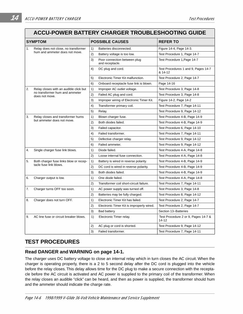
ACCU-POWER BATTERY CHARGER Test Procedures
14
TEST PROCEDURES
Read DANGER and WARNING on page 14-1.The charger uses DC battery voltage to close an internal relay which in turn closes the AC circuit. When thecharger is operating properly, there is a 2 to 5 second delay after the DC cord is plugged into the vehiclebefore the relay closes. This delay allows time for the DC plug to make a secure connection with the recepta-cle before the AC circuit is activated and AC power is supplied to the primary coil of the transformer. Whenthe relay closes an audible “click” can be heard, and then as power is supplied, the transformer should humand the ammeter should indicate the charge rate.
ACCU-POWER BATTERY CHARGER TROUBLESHOOTING GUIDE
SYMPTOM POSSIBLE CAUSES REFER TO
1. Relay does not close, no transformer hum and ammeter does not move.
1) Batteries disconnected. Figure 14-4, Page 14-3.
2) Battery voltage is too low. Test Procedure 1, Page 14-7
3) Poor connection between plugand receptacle.
Test Procedure 1,Page 14-7
4) DC plug and cord. Test Procedures 1 and 9, Pages 14-7 & 14-12
5) Electronic Timer Kit malfunction. Test Procedure 2, Page 14-7
6) Onboard receptacle fuse link is blown. Page 14-16
2. Relay closes with an audible click but no transformer hum and ammeter does not move.
1) Improper AC outlet voltage. Test Procedure 3, Page 14-8
2) Failed AC plug and cord. Test Procedure 3, Page 14-8
3) Improper wiring of Electronic Timer Kit. Figure 14-2, Page 14-2
4) Transformer primary coil. Test Procedure 7, Page 14-11
5) Relay. Test Procedure 9, Page 14-12
3. Relay closes and transformer hums but ammeter does not move.
1) Blown charger fuse. Test Procedure 4-B, Page 14-9
2) Both diodes failed. Test Procedure 4-B, Page 14-9
3) Failed capacitor. Test Procedure 6, Page 14-10
4) Failed transformer. Test Procedure 7, Page 14-11
5) Defective charger relay. Test Procedure 9, Page 14-12
6) Failed ammeter. Test Procedure 9, Page 14-12
4. Single charger fuse link blows. 1) Diode failed. Test Procedure 4-A, Page 14-8
2) Loose internal fuse connection. Test Procedure 4-A, Page 14-8
5. Both charger fuse links blow or recep-tacle fuse link blows.
1) Battery is wired in reverse polarity. Test Procedure 4-B, Page 14-9
2) DC cord is wired in reverse polarity. Test Procedure 4-B, Page 14-9
3) Both diodes failed. Test Procedure 4-B, Page 14-9
6. Charger output is low. 1) One diode failed. Test Procedure 4-A, Page 14-8
2) Transformer coil short-circuit failure. Test Procedure 7, Page 14-11
7. Charger turns OFF too soon. 1) AC power supply was turned off. Test Procedure 3, Page 14-8
2) Batteries may be fully charged. Test Procedure 8, Page 14-12
8. Charger does not turn OFF. 1) Electronic Timer Kit has failed. Test Procedure 2, Page 14-7
2) Electronic Timer Kit is improperly wired. Test Procedure 2, Page 14-7
3) Bad battery. Section 13–Batteries
9. AC line fuse or circuit breaker blows. 1) Electronic Timer relay. Test Procedure 2 or 9, Pages 14-7 & 14-12
2) AC plug or cord is shorted. Test Procedure 9, Page 14-12
3) Failed transformer. Test Procedure 7, Page 14-11
Page 14-6 1998/1999 V-Glide 36-Volt Vehicle Maintenance and Service Supplement

ACCU-POWER BATTERY CHARGER Test Procedures
14
Test Procedure 1 - Battery Voltage is Too Low or Faulty DC Plug Connection1. Check the DC plug and the receptacle for damage, dirt, corrosion, etc., that might prevent a sound
electrical connection.
2. Measure the voltage at the receptacle using a multimeter set to 200 volts DC (Figure 14-6, Page 14-7) .
3. Measure battery terminal voltage between the positive post on battery No. 1 and the negative post onbattery No. 6 (Figure 14-7, Page 14-7) . The voltage reading should be the same as at the receptacle.
4. If the voltage readings obtained at the receptacle and at the batteries are not the same, check the wireconnections at the receptacle and at the batteries. If the DC voltages are the same and within limits,remove the charger cover and verify that the charger is properly wired. With the AC cord disconnected,insert the DC plug into the charger receptacle. With a multimeter set to 200 volts DC, measure batteryvoltage at the white and black wires from the DC cord inside the charger (Figures 14-2 and 14-3,Pages 14-2 and 14-3) . The voltage reading should be the same as at the receptacle. See Test Proce-dure 9 . See DANGER and WARNING on page 14-5 .
Test Procedure 2 - Electronic Timer Kit1. Connect the charger AC plug to an outlet, then connect the DC plug to the vehicle. After a 2 to 5 sec-
ond delay, the charger should start. If the charger starts immediately (without a 2 to 5 second delay),the electronic timer relay has failed.
2. If the charger does not turn off automatically when batteries are fully charged, check the connections ofthe green wire on the heat sink and check the relay (see Test Procedure 9) . If the wire connections aresecure and the relay has not failed, the electronic timer kit must be replaced. To verify the timer is mal-functioning:
2.1. Unplug AC and DC cords and remove the cover from the charger. See DANGER on page 14-5.
2.2. Locate and carefully remove the two black wires connected to the contact terminals of the relay.
• TO CLOSE THE CHARGER RELAY, BATTERY VOLTAGE MUST BE BETWEEN 24 AND 50 VOLTS.
Figure 14-6 Voltage at Receptacle Figure 14-7 Battery Terminal Voltage
NOTE
MEASURE VOLTAGEAT RECEPTACLE
1
2
3
46
5
DISCONNECT THESE BATTERY CABLES BEFORE
WORKING ON VEHICLE
- +
2m
20m
200m
2k200
200
200200
20
2
200m
500
20k
200k
2000k
Ω
Ω
1000OFF
WAVETEK 5XLV
V
V
A
! !COM 200nA
MAX1000 ---
750V FUSED
FRONTOF VEHICLE
1998/1999 V-Glide 36-Volt Vehicle Maintenance and Service Supplement Page 14-7

ACCU-POWER BATTERY CHARGER Test Procedures
14
Test Procedure 2, Continued:
2.3. Place a relay bypass wire (14 AWG minimum) between the two black wires (Figure 14-13, Page 14-12) .
2.4. The power supply cord is now connected directly to the primary transformer coil and the trans-former should hum when the AC cord is plugged into a live outlet.
2.5. Charger operation may now be checked by connecting the DC plug into the receptacle, and thenconnecting the AC cord into an outlet. If normal charging current is indicated on the ammeter, theelectronic timer and/or the relay is defective and must be replaced. See Test Procedure 9 forrelay testing . See following CAUTION.
2.6. If the transformer does not hum and the ammeter still does not register with the relay bypassed, itwill be necessary to check the continuity of the charger AC circuit. See Test Procedure 3 .
Test Procedure 3 - AC Power and Continuity Check of AC Circuit1. Unplug AC and DC cords.
2. Check the AC line fuse or circuit breaker in the storage facility.
3. Insert the probes of a multimeter, set to 500 volts AC, into the AC outlet to check incoming AC voltage.A reading of 105 to 128 volts should be obtained.
4. If AC power is not present, have a licensed electrical contractor check the building wiring and ser-vice panel.
5. Check continuity of the AC circuit: See DANGER on page 14-5.
5.1. Carefully disconnect the two black wires attached to the contact terminals of the relay.
5.2. Connect a jumper wire between the two black wires.
5.3. With relay bypassed, check the circuit across the AC cord plug blades (Figure 14-8, Page 14-9) .
5.4. If the reading is no continuity, check the wiring of the AC cord, the transformer primary coil leads,and the jumper wire. If the charger is wired correctly, check, individually, the continuity of the ACcord, the transformer primary coil, and the jumper wire.
Test Procedure 4 - Diodes
Use Test Procedure 4-A for single diode failures and diode testing. If both diodes have failed, use Test Proce-dure 4-B.
Test Procedure 4A - Single Diode Failure
A single diode failure is indicated by the failure of one fuse link (short circuited diode) or by low charger output (opencircuit diode). If a diode has failed, the entire heat sink assembly must be replaced. To check the diodes:
1. Unplug the AC cord from its outlet and unplug the DC cord from the vehicle receptacle.
2. Disconnect one transformer secondary coil lead from the diode terminal (Figure 14-2, Page 14-2) .
3. Using a low voltage continuity tester or multimeter set to diode, place one tester probe on thediode mounting plate and the other probe on a diode terminal and note the reading (Figure 14-9,Page 14-10).
• DO NOT CHARGE BATTERIES WITH THE ELECTRONIC TIMER KIT BYPASSED. IF THE TIMERKIT IS BYPASSED, THE CHARGER WILL REMAIN OPERATING AS LONG AS THE AC CORD ISPLUGGED INTO AN OUTLET. SEVERE OVERCHARGING AND EVENTUAL DAMAGE TO THEBATTERIES WILL RESULT.
CAUTION
Page 14-8 1998/1999 V-Glide 36-Volt Vehicle Maintenance and Service Supplement

ACCU-POWER BATTERY CHARGER Test Procedures
14
4. Reverse the tester probes and check each diode again (Figure 14-10, Page 14-10) . A diode isdesigned to conduct current in only one direction. If a diode shows continuity in both directions, theentire heat sink assembly with diodes must be replaced. If a diode shows no continuity in either direc-tion, the entire heat sink assembly must be replaced.
5. Check all three fuse connections inside the charger to be sure they are clean and tight. It is possiblethat a loose internal fuse connection could create enough heat to cause a single fuse link to melt. Theproper torque on all fuse link connections is 20 in.lb. (2.3 N-m).
6. Be sure the charger is wired properly and all connections are clean and tight.
Test Procedure 4B - Both Diodes FailedUse Test Procedure 4A to test diodes. If both diodes have failed closed (shorted), both charger fuse links willbe blown. If both diodes have failed open, the relay will close and the transformer will hum, but the ammeterwill indicate no output. If both diodes have failed open or have shorted, the entire heat sink assembly must bereplaced. To determine why both diodes failed:
1. Check the batteries and the receptacle to be sure they are wired in the correct polarity. Use a multi-meter to check the voltage and polarity at the receptacle.
2. Make sure the charger DC plug is wired correctly. The white wire should be connected to the center ter-minal of the heat sink assembly and the black wire should be connected to the left side of the ammeterwhen viewed from inside the charger. Whether or not the AC cord is plugged into an outlet, both fuselinks will blow if a reversed polarity connection is made between the charger and the batteries.
3. Although it is a rare occurrence, both diodes may fail due to a lightning strike at the charging location.
4. Excessive heat due to a loose connection could also cause both fuse links to melt. Be sure fuse con-nections are tightened to 20 in.lb (2.3 N-m).
5. Make sure the charger is wired properly and all connections are clean and tight.
Test Procedure 5 - Continuity Test of Charger DC Circuit1. Connect the probes of a continuity tester (Club Car Part No. 1011273) to the blades of the charger DC
plug and note the reading (Figure 14-11, Page 14-10) .
• IF CONNECTIONS ARE NOT CLEAN AND TIGHT, EXCESSIVE HEAT WILL BE CREATED ANDTHE CHARGER MAY BE DAMAGED.
Figure 14-8 Test AC Plug Blades
CAUTION
1998/1999 V-Glide 36-Volt Vehicle Maintenance and Service Supplement Page 14-9

ACCU-POWER BATTERY CHARGER Test Procedures
14
Test Procedure 5, Continued:
2. Reverse the probes (Figure 14-12, Page 14-10) and note the reading.
3. Continuity should be observed in only one direction. If the circuit shows no continuity in either directionand the fuse is functional, check the continuity of the DC plug and cord (Test Procedure 9) , the amme-ter (Test Procedure 9) , the diodes (Test Procedure 4A) , and all connections.
4. If the circuit indicates continuity in both directions, a short circuit exists in the charger DC circuit, proba-bly caused by failed diodes (see Test Procedure 4) . If the diodes have not failed, check the DC outputcord for a short circuit between the two wires (Test Procedure 9) .
5. If the test shows the charger DC circuit is functional, check the capacitor (Test Procedure 6) .
Test Procedure 6 - Capacitor
Figure 14-9 Single Diode Test Figure 14-10 Reverse Tester Leads
Figure 14-11 Charger DC Plug Figure 14-12 Charger DC Plug, Reverse Probes
• HIGH VOLTAGE! WITH THE CHARGER ON, THE VOLTAGE OF THE CAPACITOR INSIDE THECHARGER IS APPROXIMATELY 650 VOLTS. USE EXTREME CAUTION WHEN WORKINGNEAR CAPACITOR TERMINALS.
• TO AVOID BREAKING WIRES, DISCONNECT CAPACITOR LEADS CAREFULLY.
DISCONNECTSECONDARYCOIL LEAD
PULL HEREPULL HEREPULL HERE++++
PULL HEREPULL HEREPULL HERE++++
DANGER
CAUTION
Page 14-10 1998/1999 V-Glide 36-Volt Vehicle Maintenance and Service Supplement

ACCU-POWER BATTERY CHARGER Test Procedures
14
1. Disconnect both transformer coil leads from the capacitor terminals.
2. Using insulated pliers, place uninsulated tips onto capacitor terminal ends to discharge controller.
3. Place probes of a multimeter, set to 2000k ohms (Ω), on the capacitor terminals and note the reading.
4. Reverse the probes and note the reading.
5. Interpret the readings as follows:
• Functional Capacitor - When the multimeter probes are connected to the capacitor terminals, initiallymeter indicates low resistance then rapidly moves to high resistance and eventually to open circuit.
• Open Capacitor - When the multimeter leads are connected to the capacitor terminals, and the meterdoes not indicate any initial resistance and only open circuit, the capacitor has failed open. A bulge inthe top of the capacitor may be visible if the capacitor has failed open.
• Shorted Capacitor - When the multimeter probes are connected to the capacitor terminals, and themeter indicates a closed circuit and does not change, the capacitor has failed closed.
6. If the capacitor is open or shorted, it must be replaced.
Test Procedure 7 - TransformerFailure of the transformer could be caused by natural aging or premature shorting of adjacent coil turns. If thetransformer has failed, ammeter would indicate no output or low output even though the transformer mighthum. A failed transformer could cause an AC line fuse to blow or a circuit breaker to trip in the storage facility.To check the transformer:
1. Disconnect the transformer secondary coil leads (1) and (4) from the diode terminals (Figure 14-13,Page 14-12). Remount nuts on diode assembly. See following DANGER .
2. Disconnect the transformer capacitor coil leads (5) and (6) from the capacitor terminals (Figure 14-13,Page 14-12). See following DANGER.
3. In order to supply AC power directly to transformer coil, relay must be bypassed. Refer to Test Procedure 2.4. Make sure the capacitor coil leads and the secondary coil leads are not touching one another. Then, with
the relay by-passed, plug the AC cord into an outlet. If the AC line fuse blows or the circuit breaker trips, thetransformer has failed internally and must be replaced.
5. If this does not occur, use a multimeter, set to 500 volts AC, to check transformer secondary voltage acrosslead Nos. 1 and 4, and capacitor coil voltage across lead Nos. 5 and 6 (Figure 14-13, Page 14-12). If mea-sured voltages are approximately 48 volts or lower for secondary coil, or less than approximately 385 voltsfor capacitor, the transformer is shorted internally and must be replaced. See previous DANGER .
6. If the transformer output voltages are correct, disconnect the AC cord from the outlet and proceed as follows:
• USE A CLUB CAR CAPACITOR (PART NO. 1015910) ONLY. THE USE OF A DIFFERENT VALUECAPACITOR MAY RESULT IN IMPROPER CHARGING, CAPACITOR FAILURE, TRANSFORMERBURNOUT, AND/OR BATTERY DAMAGE.
• DO NOT ALLOW THE SECONDARY COIL LEADS TO TOUCH EACH OTHER. THERE AREAPPROXIMATELY 61 VOLTS AC PRESENT.
• DO NOT ALLOW THE CAPACITOR COIL LEADS TO TOUCH EACH OTHER. THERE AREAPPROXIMATELY 650 VOLTS AC PRESENT.
• HIGH VOLTAGE! WITH THE CHARGER ON, THE VOLTAGE OF THE CAPACITOR INSIDE THECHARGER IS APPROXIMATELY 650 VOLTS. USE EXTREME CAUTION WHEN WORKINGNEAR CAPACITOR TERMINALS.
WARNING
DANGER
1998/1999 V-Glide 36-Volt Vehicle Maintenance and Service Supplement Page 14-11

ACCU-POWER BATTERY CHARGER Test Procedures14
Test Procedure 7, Continued :
6.1. Check the capacitor to be sure its rating is 3 microfarads (capacitor should be marked), 660 voltsAC, and then carefully reconnect the capacitor coil lead Nos. 5 and 6 to the capacitor terminals.
6.2. After making sure the secondary coil leads are not touching one another, connect the AC cord toan outlet and measure the transformer secondary voltage across lead Nos. 1 and 4.
6.3. If the voltage reading is the same as the voltage reading in step 5 (which eliminates the capacitorfrom the circuit), the capacitor may be defective or the coil leads may not be making proper elec-trical contact (see Test Procedure 6) . If the voltage readings are correct, both the transformerand the capacitor are functional; refer to Test Procedure 5 for further tests of the DC circuit.
Test Procedure 8 - Battery State of Charge Test1. When the charger has turned off after a charge cycle, disconnect and then reconnect the charger AC
plug. The ammeter should jump to 18-22 amps and taper to below 12 amps within 15 minutes. If ittapers to below 12 amps within 15 minutes, the batteries are fully charged and the charger is function-ing properly.
2. If the charger does not taper to below 12 amps within 15 minutes, the batteries may not be receiving afull charge and the Electronic Timer Kit should be checked. See Test Procedure 2 .
Test Procedure 9 - Continuity Tests
AC Cord and Plug1. Disconnect black wire (1) of AC cord from the contact terminal of the relay (Figure 14-14, Page 14-13) .
2. Disconnect the green wire (2) from the charger case (Figure 14-14, Page 14-13) .
3. Connect the alligator clip of a continuity tester (Club Car Part No. 1011273) to the end of the black wire(1) and check for continuity on both flat blades and on the ground blade of the AC plug (Figure 14-14,Page 14-13). Continuity should be shown on only one flat blade. If continuity is indicated on more thanone blade or on no blade, the AC cord and plug must be replaced.
Figure 14-13 Relay Bypass Wire Placement
• OLD BATTERIES NEAR THE END OF THEIR USEFUL LIVES MAY NOT TAPER TO BELOW 12AMPS. SEE SECTION 13–BATTERIES .
RE
LAY
TR
AN
SF
OR
ME
R
RED
RED
BLACK (-)
BLA
CK
BLA
CK
TO BATTERIES
DC CORDSET
WHITE OR RED (-)
ORANGE BROWN
BLACK
BLACK
BLACK
GREEN
GREEN
CASE GROUND
WHITE
TAN
TAN
TANTAN
TAN
CAPACITOR
AC INPUTPLUG
AC CORDSET
ELECTRONICTIMER ASS'Y
CO
NT
RO
LC
AB
LE A
SS
'Y1
2
3
4
5
FUSE ASSEMBLY AMMETER
RELAYBYPASS
SECONDARY
PRIMARY
56 1
4
3 2
NOTE
Page 14-12 1998/1999 V-Glide 36-Volt Vehicle Maintenance and Service Supplement

ACCU-POWER BATTERY CHARGER Test Procedures 14
4. Disconnect white wire terminal connector (4) at the transformer lead. Insert red probe into the whitewire terminal end (4). Place black probe on each flat blade and then on the ground pin and check forcontinuity. Continuity should be shown on only one flat blade. If tester indicates continuity on more thanone blade or on no blade, the AC cord and plug must be replaced (Figure 14-14, Page 14-13) .
5. Attach alligator clip to end of green wire (2) and check for continuity on both flat blades and ground pin of ACplug (Figure 14-14, Page 14-13) . Continuity should be shown on only ground pin. If continuity is indicatedon flat blades or is not indicated on ground pin, AC cord and plug must be replaced.
DC Cord and Plug1. Disconnect the black wire (5) of the DC cord from the ammeter, and disconnect the white wire of the
DC cord from the heat sink assembly (Figure 14-15, Page 14-15) .
2. Attach alligator clip of continuity tester to the white wire (6) of the DC cord (Figure 14-15, Page 14-15) .
3. Place the probe of the continuity tester on the positive (+) blade of the DC plug (the positive and nega-tive blades are identified on the plug). The tester should indicate continuity. If the tester does not indi-cate continuity, the DC cord and plug must be replaced.
4. Place the probe of the tester on the negative (-) blade of the DC plug. The tester should indicate nocontinuity. If the tester indicates continuity, the cord and plug must be replaced.
5. Attach alligator clip to the black wire (5) of the DC cord and then place the probe on the negative (-)blade of the DC plug (Figure 14-15, Page 14-15) . The tester should indicate continuity. Place the probeon the positive (+) side. The reading should be no continuity. If the readings are not correct, the cordand plug must be replaced.
TransformerThe transformer has three coils that must be tested (Figure 14-3, Page 14-3) .
1. Test the Primary Coil:
1.1. Disconnect the transformer primary coil leads from the terminals.
1.2. Place the continuity tester probes on the primary coil leads. The tester should indicate continuity.If the tester indicates no continuity, replace the transformer.
2. Test the Secondary Coil:
2.1. Disconnect the transformer secondary coil lead from the upper terminal of the heat sink assembly.
2.2. Disconnect the other transformer secondary coil lead from the upper terminal of the heat sinkassembly, then place the tester probes on the secondary coil leads (tan wires). The readingshould be continuity. If the reading is no continuity, replace the transformer. Be sure the fuse isintact and has not failed. See DANGER on page 14-11 .
Figure 14-14 AC Plug
- +
2m
20m
200m
2k200
200
200200
20
2
200m
500
20k
200k
2000k
Ω
Ω
1000OFF
WAVETEK 5XLV
V
V
A
! !COM 200nA
MAX1000 ---
750VFUSED
2
1
34
1998/1999 V-Glide 36-Volt Vehicle Maintenance and Service Supplement Page 14-13

ACCU-POWER BATTERY CHARGER Plug and Receptacle Replacement14
Transformer, Continued:3. Test the Capacitor Coil:
3.1. Disconnect the transformer capacitor coil leads from the capacitor terminals.
3.2. Place the tester probes on the capacitor coil leads. The reading should be continuity. If the read-ing is no continuity, replace the transformer.
Relay
1. Disconnect the two black wires from the contact terminals of the relay.
2. Place the continuity tester probes on the contact terminals of the relay. The reading should be no con-tinuity. If the tester shows continuity, the relay contacts are welded shut and the relay must be replaced.
3. Plug the DC cord into a vehicle receptacle (make sure the vehicle batteries are connected), then placethe tester probes on the contact terminals of the relay. The reading should be continuity; if the testershows no continuity, the relay must be replaced.
Ammeter1. Disconnect both black wires from the left (when viewed from inside the charger) ammeter post.
2. Attach the alligator clip of the tester to one of the ammeter posts.
3. Place the tester probe on the other ammeter post. The reading should be continuity. If the tester indi-cates no continuity, the ammeter must be replaced.
PLUG AND RECEPTACLE REPLACEMENT
Read DANGER and WARNING on page 14-1.The charger DC cord and plug, and the charger receptacle on the vehicle are wear items that should beinspected daily. They must be replaced when worn or damaged. If the charger plug and receptacle showsigns of corrosion or are becoming difficult to insert and remove, the receptacle contacts and plug blades canbe cleaned with a good electrical contact cleaner or lightly sprayed with WD-40® brand spray lubricant.
TESTING THE RECEPTACLE1. Inspect the receptacle for cracks, loose connections and frayed wiring.
2. Insert the tapered end of a test blade (Club Car Part No. 1013930) approximately 1-1/2 in. (38 mm) into oneside of the receptacle, then withdraw the blade from the contact, pulling straight out from the receptacle.
3. Repeat for the other contact. Both contacts must grip the test blade well enough to create sufficient pressure(or drag) for an adequate electrical connection. If little or no drag is felt, the receptacle must be replaced.
CHARGER DC CORD REPLACEMENT
DC Cord Removal1. Unplug the AC and DC cords and remove the charger cover. See DANGER and WARNING on page 14-5.
2. Disconnect the black lead of the DC cord from the ammeter by loosening the nut (1). Support the termi-nal as the nut is loosened to prevent rotation of the connection. Leave the black wire from the electronictimer (4) on the terminal post (Figure 14-15, Page 14-15) .
3. Remove the nut that retains the white lead of the DC cord on the heat sink assembly. Leave the redwire from the electronic timer on the screw at the heat sink assembly.
4. Using pliers, squeeze the strain relief bushing and remove the cord set.
• BEFORE PERFORMING THIS TEST, MAKE SURE THE AC PLUG IS NOT PLUGGED IN.
WARNING
Page 14-14 1998/1999 V-Glide 36-Volt Vehicle Maintenance and Service Supplement

ACCU-POWER BATTERY CHARGER Plug and Receptacle Replacement 14
DC Cord Installation1. Insert the leads of the new cord through the hole in the charger base.
2. Make sure the red wire of the electronic timer is on the middle terminal of the heat sink assembly, thenplace the white lead of the new cord on the terminal and tighten the nut to 14 in.lb (1.5 N-m).
3. Make sure the black wire (4) of the electronic timer is on the ammeter post. Attach the black lead (5) ofthe new cord and tighten nut (1) on the post until finger tight (Figure 14-15, Page 14-15). See follow-ing CAUTION .
4. While holding the outside of the nut (1), turn the inside nut (2) counterclockwise 1/4 turn (Figure 14-15,Page 14-15). See previous CAUTION and following NOTE.
5. Place the strain relief bushing on the cord and use pliers to insert bushing into the charger base.
6. Place the charger cover in position and install the mounting screws, starting with the bottom holes.Tighten the screws to 11 in.lb (1.2 N-m).
RECEPTACLE REPLACEMENT
Figure 14-15 DC Cord
• DO NOT ALLOW AMMETER POST TO ROTATE AS NUT IS TIGHTENED. IF IT ROTATES, THEAMMETER COULD BE DAMAGED.
• CHECK THE POSITIONS OF THE TERMINALS TO MAKE SURE THEY ARE NOT TOUCHING THEAMMETER BUS BAR (3) OR THE AMMETER POST (FIGURE 14-15, PAGE 14-15).
• REMOVE KEY AND PLACE FORWARD/REVERSE HANDLE IN THE NEUTRAL POSITION.
• DISCONNECT THE BATTERIES AS SHOWN IN FIGURE 14-4, PAGE 14-3.
5
4
2
3
1
6
CAUTION
NOTE
WARNING
1998/1999 V-Glide 36-Volt Vehicle Maintenance and Service Supplement Page 14-15

ACCU-POWER BATTERY CHARGER Plug and Receptacle Replacement14
Receptacle Removal1. Disconnect the small black wire (15) and the white wire (14) (to the negative battery post) from the neg-
ative terminal of the receptacle (Figure 14-16, Page 14-16).2. Disconnect the red wire (11) (to the fuse link) from the positive terminal of the receptacle and remove
the four screws (1) from the bezel (2) (Figure 14-16, Page 14-16). See following WARNING .
3. Remove screws (3 and 18) attaching receptacle to the fuse link bracket (4) (Figure 14-16, Page 14-16) .
Receptacle Installation 1. Install the screws (3 and 18) which attach the receptacle (13) to the fuse link bracket (4) (Figure 14-16,
Page 14-16). Tighten the screws to 20 in.lb (2.2 N-m).
2. Install red wire of fuse link to positive (+) terminal of receptacle (the positive (+) and negative (-) termi-nals are labeled on face of receptacle) (Figure 14-16, Page 14-16) . Tighten nut to 23 in.lb (2.6 N-m).
3. Install the small black wire (from wiper switch) and the white wire (from negative battery post) on thenegative (-) terminal of the receptacle (Figure 14-16, Page 14-16) . Tighten nut to 23 in.lb (2.6 N-m).
4. Position bezel (2) and fuse link bracket (4) and install the four mounting screws (1) through the bezeland into the fuse link bracket (Figure 14-16, Page 14-16) . Tighten the screws to 20 in.lb (2.2 N-m).
ONBOARD RECEPTACLE FUSE LINKIf the receptacle fuse link has failed, the vehicle cannot be charged until the fuse has been replaced. Thefuse link (7) is located on the fuse link bracket (4) in the battery compartment (rear portion of the chargerreceptacle) (Figure 14-16, Page 14-16) . See also Figure 14-4, Page 14-3 .
Figure 14-16 Receptacle
• MAKE SURE THE BLACK AND WHITE WIRES DO NOT TOUCH.
1
218
5
6
7
17
8
19
20
1116
13
4
12
TYPICAL2 PLACES
TYPICAL2 PLACES
TYPICAL2 PLACES
TYPICAL2 PLACES
TYPICAL4 PLACES
TYPICAL2 PLACES
VEHICLEBODY
3
15
14
109
WARNING
Page 14-16 1998/1999 V-Glide 36-Volt Vehicle Maintenance and Service Supplement
ACCU-POWER BATTERY CHARGER Charger Repairs 14
Receptacle Fuse Link Removal1. Remove the two screws (5) and then the lens (6) (Figure 14-16, Page 14-16) .
2. Remove the outer nuts (20), lockwashers (19), and wires (9, 10, and 11) (Figure 14-16, Page 14-16) .
3. Remove the remaining nuts (8) (Figure 14-16, Page 14-16) .
4. Remove the fuse link (7) from the base (17) (Figure 14-16, Page 14-16).
Receptacle Fuse Link Installation1. Install a new fuse link (7) (Club Car Part No. 1014516) into the base (17) (Figure 14-16, Page 14-16).
2. Install nuts (8) which attach fuse link to base and tighten to 18 in.lb (2.0 N-m) (Figure 14-16, Page 14-16).
3. Connect the red wire (9) (from the forward and reverse switch) and the orange wire (10) (from the reversebuzzer) to the passenger side of the fuse assembly and install the lock washer (19) and outer nut (20).Tighten the nut to 23 in.lb. (2.5 N-m) (Figure 14-16, Page 14-16). See also Figure 14-4, Page 14-3.
4. Connect the red wire (11) (from the charger receptacle) to the driver’s side of the fuse assembly andinstall the lock washer (19) and nut (20). Tighten the nut to 23 in.lb (2.5 N-m).
5. Install fuse link assembly and cover (6). Tighten screws (5) to 20 in.lb (2.2 N-m) (Figure 14-16, Page 14-16) .
CHARGER REPAIRS
Read DANGER and WARNING on page 14-1.
ELECTRONIC TIMER KIT
Electronic Timer Kit Removal1. Remove the two screws attaching the electronic timer assembly to the face of the charger.
2. Slide the electronic timer assembly from the charger and carefully remove the control cable connectorfrom the timer.
Electronic Timer Kit Installation1. Carefully connect the control cable connector to the new timer and slide the timer assembly into the charger.
2. Install the two timer assembly retaining screws in the face of the charger.
Electronic Timer Relay WiringIf the wires from the relay were disconnected, connect them to the numbered relay terminals as follows:
1. Attach the orange wire to terminal No. 6.
2. Attach the brown wire to terminal No. 1.
3. Attach the black wire from the AC cord to terminal No. 3.
4. Attach the black extension wire from the transformer primary coil to terminal No. 5.
• UNDER NORMAL OPERATING CONDITIONS, THE RECEPTACLE FUSE LINK SHOULD NEVERFAIL UNLESS THERE IS AN ELECTRICAL PROBLEM. IF THE FUSE BLOWS, DETERMINE THECAUSE OF THE PROBLEM AND CORRECT IT BEFORE REPLACING THE FUSE.
• MAKE SURE ALL CONNECTIONS ARE CLEAN AND TIGHT. MAKE SURE ALL WIRES ANDTERMINALS ARE POSITIONED SO THEY DO NOT SHORT TOGETHER OR TO CHARGER BASE.
WARNING
WARNING
1998/1999 V-Glide 36-Volt Vehicle Maintenance and Service Supplement Page 14-17
ACCU-POWER BATTERY CHARGER Charger Repairs14
Checking Proper Operation of Electronic Timer Kit1. With the DC plug disconnected from the receptacle, plug the AC cord into an outlet. The relay on the
electronic timer kit should not close. A multimeter set to 200 volts DC and connected across the DCplug should indicate zero volts. The transformer should not hum.
2. Unplug the AC cord from its outlet and connect the DC plug to the receptacle. The relay, located next tothe electronic timer kit, should close with an audible “click” after a two to five second delay.
3. If the electronic timer kit does not operate as in step one or two above, refer to the wiring diagram (Fig-ure 14-2, Page 14-2) and make sure the charger is wired correctly. If the electronic timer kit operatesproperly, the charger is ready for use. Always monitor the first charge cycle to verify the charger is turn-ing OFF properly.
CAPACITOR
Capacitor Removal1. Remove the charger cover. See DANGER on page 14-5.2. Loosen the mounting band screw (Figure 14-17, Page 14-18) . See CAUTION on page 14-10 .3. Remove the connectors from the capacitor terminals.
4. Pull the capacitor out of the band.
Capacitor Installation1. Route the capacitor wires through the band and then slide the capacitor into the band.
2. Tighten the mounting band screw.
3. Connect the terminal connectors to the capacitor terminals.
4. Install the charger cover and check the charger for proper operation.
HEAT SINK ASSEMBLY
Heat Sink Assembly Removal1. Remove the charger cover. See DANGER on page 14-5.
2. Disconnect both secondary transformer leads (tan) from the heat sink assembly.
3. Disconnect the red, green, and white wires from the heat sink assembly.
4. Remove the nuts and bolts which secure the heat sink assembly to the case.
Figure 14-17 Capacitor
MOUNTING BAND SCREW
CAPACITOR
Page 14-18 1998/1999 V-Glide 36-Volt Vehicle Maintenance and Service Supplement

ACCU-POWER BATTERY CHARGER Charger Repairs 14
Heat Sink Assembly Installation1. Mount the heat sink assembly to the charger case. Make sure the clear plastic strip, which is coated
with a white di-electric grease, is against the charger case and install the nuts and bolts that secure theassembly to the charger case. Tighten the bolts to 13 in.lb (1.4 N-m).
2. Connect the white wire from the DC cord and the red wire of the control cable to the center connectorof the heat sink assembly. Tighten the nut to 13 in.lb (1.4 N-m).
3. Connect the green wire of the control cable and one of the secondary transformer leads (tan) to thebottom connector of the heat sink assembly. Tighten the nut to 13 in.lb (1.4 N-m).
4. Connect the other secondary transformer lead (tan) to the top connector of the heat sink assembly.
5. Install the charger cover and check the charger for proper operation.
TRANSFORMER
Transformer Removal1. Remove the charger cover (Figure 14-3, Page 14-3) . See DANGER on page 14-5.2. Disconnect the black extension wire and the transformer primary coil lead, then disconnect the white
wire in the AC cord and the transformer coil lead.
3. Disconnect the secondary transformer leads from the heat sink assembly.
4. Disconnect the secondary transformer leads from the fuse assembly.
5. Disconnect the capacitor coil leads from the capacitor. See DANGER on page 14-11.
6. Remove the plastic wire tie holding the red and green wires of the control cable and one secondarytransformer lead (from the heat sink assembly) together.
7. Remove the four bolts and nuts from the transformer and remove the transformer.
Transformer Installation1. Position the transformer in the charger, oriented with the secondary coil lead to the rear. Install the four
mounting bolts and nuts and tighten them to 28 in.lb (3.0 N-m).
2. Connect one secondary transformer lead (tan) to the top of the heat sink assembly. Tighten the nut to13 in.lb (1.4 N-m).
3. Connect the green wire of the control cable and the other secondary transformer lead (tan) to the bot-tom terminal of the heat sink assembly. Tighten the nut to 23 in.lb (2.5 N-m).
4. Connect one secondary transformer lead (black) to one terminal of the fuse assembly. Tighten the nutto 23 in.lb (2.5 N-m).
5. Connect the other secondary transformer lead (black) to the remaining terminal of the fuse assembly.Tighten the nut to 23 in.lb (2.5 N-m).
6. Connect the capacitor coil leads to the capacitor.
7. Tie the wires together as they were before the wire tie was removed.
8. Install the charger cover and check the charger for proper operation. See following WARNING .
AMMETER
Ammeter Removal1. Remove the charger cover. See DANGER on page 14-5 .2. Disconnect all wires (4 and 5) and the bus bar (3) from the ammeter posts (Figure 14-18, Page 14-20) .
3. Remove nuts (2) attaching ammeter to charger face, and remove the ammeter (Figure 14-18, Page 14-20) .
• MAKE SURE WIRING OR WIRING HARNESS IS PROPERLY SECURED TO THE VEHICLEFRAME. FAILURE TO PROPERLY SECURE WIRING COULD RESULT IN VEHICLEMALFUNCTION, PROPERTY DAMAGE OR SEVERE PERSONAL INJURY.
WARNING
1998/1999 V-Glide 36-Volt Vehicle Maintenance and Service Supplement Page 14-19

ACCU-POWER BATTERY CHARGER Charger Repairs14
Ammeter Installation1. Position the ammeter in the charger face and install the mounting nuts. See DANGER on page 14-5.
2. Install the ammeter bracket on the back of the ammeter.
3. Connect the black wire (4) of the electronic timer kit and the black wire (5) of the DC cord to the left postof the ammeter (when viewed from the rear of the charger) (Figure 14-18, Page 14-20) .
4. Connect the bus bar (3) from the fuse link to the right post of the ammeter. Make sure there is a washeron each side of the bus bar.
5. Install the nuts on both posts of the ammeter and tighten slightly more than finger tight. Then whileholding the outside nut, turn the inside nut counterclockwise 1/4 turn. See CAUTION on page 14-15.
6. Install the charger cover.
7. Plug the charger into a vehicle and make sure the ammeter is operating properly.
CHARGER FUSE LINK
Fuse Link Assembly Removal1. Remove the charger cover. See DANGER on page 14-5 .2. Remove both secondary transformer leads and the bus bar from the back of the fuse link assembly.
3. Remove the fuse link retaining screws from the face of the charger and remove the fuse link assembly.
Fuse Link Assembly Installation1. Place the plastic cover over the fuse assembly and position the assembly on the charger face, then
install the mounting screws from the front of the charger face.
2. Install the bus bar over center branch of fuse assembly and ammeter post. Tighten to 23 in.lb (2.6 N-m).
3. Connect one of the secondary transformer leads (black) to one of the remaining terminals on the backof the fuse assembly. Connect the remaining secondary transformer lead (black) to the remaining ter-minal. Tighten to 23 in.lb (2.6 N-m).
4. Install the charger cover.
Figure 14-18 Ammeter
5
6
4
2
3
1
Page 14-20 1998/1999 V-Glide 36-Volt Vehicle Maintenance and Service Supplement

15
SECTION 15–MOTOR
• BATTERY - EXPLOSIVE GASES! DO NOT SMOKE. KEEP SPARKS AND FLAMES AWAY.VENTILATE WHEN CHARGING OR USING IN AN ENCLOSED SPACE. ALWAYS WEARFULL FACE SHIELD WHEN WORKING ON OR NEAR BATTERIES.
• USE EXTREME CAUTION WHEN USING TOOLS, WIRES, OR METAL OBJECTS NEARBATTERIES! A SHORT CIRCUIT AND (OR) SPARK COULD CAUSE AN EXPLOSION.
• BATTERY - POISON! CONTAINS ACID! CAUSES SEVERE BURNS. AVOID CONTACT WITHSKIN, EYES, OR CLOTHING. ANTIDOTES:- EXTERNAL: FLUSH WITH WATER. CALL A PHYSICIAN IMMEDIATELY.- INTERNAL: DRINK LARGE QUANTITIES OF MILK OR WATER. FOLLOW WITH MILK OF
MAGNESIA OR VEGETABLE OIL. CALL A PHYSICIAN IMMEDIATELY.- EYES: FLUSH WITH WATER FOR FIFTEEN MINUTES. CALL PHYSICIAN IMMEDIATELY.
• ONLY TRAINED TECHNICIANS SHOULD REPAIR OR SERVICE THIS VEHICLE. ANYONE DOINGEVEN SIMPLE REPAIRS OR SERVICE SHOULD HAVE KNOWLEDGE AND EXPERIENCE INGENERAL ELECTRICAL REPAIR. FOLLOW ALL PROCEDURES EXACTLY AND HEED ALLWARNINGS STATED IN THIS MANUAL.
• WEAR SAFETY GLASSES OR APPROVED EYE PROTECTION WHILE SERVICING VEHICLE.
• TURN KEY SWITCH OFF, PLACE FORWARD/REVERSE HANDLE IN THE NEUTRAL POSITION,AND REMOVE KEY PRIOR TO SERVICING.
• DO NOT WEAR LOOSE CLOTHING. REMOVE JEWELRY SUCH AS RINGS, WATCHES, CHAINS,ETC. BEFORE SERVICING VEHICLE.
• ALWAYS USE INSULATED TOOLS WHEN WORKING NEAR BATTERIES OR ELECTRICALCONNECTIONS.
• TO AVOID UNINTENTIONALLY STARTING THE VEHICLE, DISCONNECT BATTERIES AS SHOWNIN FIGURE 15-1, PAGE 15-1.
Figure 15-1 V-Glide 36-Volt Battery Configuration
DANGER
WARNING
1
2
3
46
5
FRONTOF VEHICLE
DISCONNECT THESE BATTERY CABLES BEFORE
WORKING ON VEHICLE
1998/1999 V-Glide 36-Volt Vehicle Maintenance and Service Supplement Page 15-1

MOTOR General Information
15
GENERAL INFORMATION
All DS V-Glide electric vehicles are equipped with 36-volt DC, series wound, reversible traction motors. If themotor should require major repair, it should be sent to a qualified motor repair shop. There are, however, manyminor repairs that can be made by a trained mechanic.
EXTERNAL MOTOR TESTING
Using a multimeter or a continuity tester, the following tests can be performed without disassemblingthe motor.
Test Procedure 1 - Internal Short Circuits
1. Disconnect the wires from the terminals on the motor. See following NOTE.
2. Using a multimeter set to ohms, place the black (-) probe on the motor housing (it may be necessary toscrape the paint from the area to insure a sound connection). Place the red (+) probe on the A1, A2,S1, and S2 terminals respectively (Figure 15-2, Page 15-2) . Multimeter should indicate no continuity. Ifthe readings are incorrect, the motor will need to be removed from the vehicle and repaired by a quali-fied technician. See Motor Removal .
2.1. An incorrect reading from the A1 or A2 terminal indicates three possible problems; a grounded A1or A2 terminal, a grounded wire in the brush area, or a grounded armature/commutator. If the S1or S2 reading is incorrect, it could be due to a grounded S1 or S2 terminal or a grounded field coil.
Test Procedure 2 - Armature Circuit Open1. Using two wrenches to prevent the post from turning, disconnect the wires from the A1 and A2 terminals.
Using a multimeter set to ohms, place red (+) probe on the A1 terminal and the black (-) probe on the A2terminal (Figure 15-2, Page 15-2) . The reading should be continuity. If the reading is incorrect, a possibleopen or poor contact in a brush assembly and/or open armature windings may be the cause. The motorwill need to be removed from the vehicle and repaired by a qualified technician. See Motor Removal .
Test Procedure 3 - Field Circuit Open1. Using two wrenches to prevent the post from turning, disconnect the wires from the S1 and S2 termi-
nals. Using a multimeter set to ohms, place the red (+) probe on the S1 terminal and the black (-) probe
• TAG THE MOTOR WIRES FOR IDENTIFICATION BEFORE DISCONNECTING.
Figure 15-2 Test for Motor Short Circuits
NOTE
S1A1
S2A2
Page 15-2 1998/1999 V-Glide 36-Volt Vehicle Maintenance and Service Supplement

MOTOR Motor Removal and Disassembly
15
on the S2 terminal (Figure 15-2, Page 15-2) . The reading should be continuity. If the reading is incor-rect, there may be an open field coil or bad connections at terminals. Remove motor from vehicle andsend to a qualified technician for repair. See Motor Removal .
MOTOR REMOVAL AND DISASSEMBLY
Read DANGER and WARNING on page 15-1.
MOTOR REMOVAL1. Disconnect the battery cables, negative cable first (Figure 15-1, Page 15-1) .
2. Using two wrenches to prevent the post from turning, disconnect motor wires. Label the wires to ensureproper reconnection. See NOTE on page 15-1. Slightly loosen all lug nuts on both rear wheels.
3. Place floor jack under transaxle and raise rear of vehicle (Figure 15-3, Page 15-3) then place jackstandsunder frame cross-member between spring mount and side stringer, just forward of each rear wheel. Lowerthe vehicle to let jackstands support vehicle (Figure 15-4, Page 15-3) . See following WARNING .
• LIFT ONLY ONE END OF THE VEHICLE AT A TIME. BEFORE LIFTING, LOCK THE BRAKES ANDCHOCK THE WHEELS THAT REMAIN ON THE FLOOR. USE A SUITABLE LIFTING DEVICE(CHAIN HOIST OR HYDRAULIC FLOOR JACK) WITH 1000 LBS. (454 KG.) MINIMUM LIFTINGCAPACITY. DO NOT USE LIFTING DEVICE TO HOLD VEHICLE IN RAISED POSITION. ALWAYSUSE APPROVED JACKSTANDS OF PROPER WEIGHT CAPACITY TO SUPPORT THE VEHICLE.
Figure 15-3 Support Transaxle on Floor Jack Figure 15-4 Support Vehicle on Jackstands
Figure 15-5 Lower Axle
WARNING
Club Car
1998/1999 V-Glide 36-Volt Vehicle Maintenance and Service Supplement Page 15-3

MOTOR Motor Removal and Disassembly
15
Motor Removal, Continued:4. Remove both rear wheels.
5. Remove the nut, cup washer, and bushing from the bottom side of the shock absorber. Compress theshock absorber (pushing upwards) to move it out of the way.
6. With the floor jack underneath the transaxle, remove the nuts and bolts mounting the rear leaf springsto the shackles.
7. To gain easier access to the motor, lower the transaxle as low as it will go. If more room is needed, removethe jack from beneath the transaxle and allow the springs to rest on the floor (Figure 15-5, Page 15-3) .
8. Remove the four bolts that mount the motor to the transaxle.
9. Carefully slide the motor away from the transaxle until the motor spline disengages the input shaft.Remove the motor from the vehicle.
MOTOR DISASSEMBLY1. Before beginning disassembly, match mark motor end shield and stator shell. Place motor in vice with
wooden blocks as shown (Figure 15-9, Page 15-6) .
2. Remove the four bolts (8) securing the end shield (10) to the stator shell (2) (Figure 15-9, Page 15-6) .
3. Remove two screws (9) attaching the end shield to the bearing retainer (16) (Figure 15-14, Page 15-10) .
4. Slide the stator shell (2) off the armature (17) (Figure 15-9, Page 15-6). 5. Remove the two screws (11) attaching the brush rigging (12) to the stator shell (Figure 15-14, Page 15-10) .
6. Mark the brush terminal posts (A1 and A2) (27, 28) to identify their positions in the stator shell.Remove the nuts (6) and flat washers (5) (Figure 15-14, Page 15-10) . From the outside, push theposts through the stator shell wall and into the interior of the stator shell.
7. Carefully remove the brush rigging and the terminal posts from the stator shell.
8. To remove the brush springs (14) from the rigging, lift the spring extensions out of and over the brushmounts and then slide the springs off their mounting tabs (Figure 15-14, Page 15-10). See also Fig-ure 15-7, Page 15-4 .
• DO NOT PLACE FINGERS OR HANDS UNDER MOTOR DURING REMOVAL. SEVERE INJURYCOULD RESULT IF FINGERS OR HANDS ARE CAUGHT BETWEEN MOTOR AND AXLE TUBE.
Figure 15-6 Brush Spring Tension Figure 15-7 Brush Spring Removal
CAUTION
REPLACE SPRINGS WHICH APPLY A FORCE OF LESS
THAN 16 OUNCES
05
101520253035404550
Page 15-4 1998/1999 V-Glide 36-Volt Vehicle Maintenance and Service Supplement

MOTOR Testing and Inspecting Individual Components
15
TESTING AND INSPECTING INDIVIDUAL COMPONENTS
Read DANGER and WARNING on page 15-1.
ARMATURE1. Disassemble the motor and carefully inspect the armature. Look for these defects:
• Burned, charred or cracked insulation.
• Improperly cured varnish.
• Thrown solder.
• Flared armature windings.
• Damaged armature core laminations.
• Worn, burned or glazed commutators.
• Dirty or oily commutators.
• Raised commutator bars.
• Worn armature bearing or shaft.
If dirt or oil is discovered on commutator, commutator should be cleaned and wiped dry. Make note of anydefects discovered during inspection. This information will be useful when determining actual cause of fail-ure. Slight roughness on the commutator can be polished smooth with 400 grit or finer sandpaper.
ARMATURE GROUND TEST
1. With multimeter set to ohms, place one probe on commutator and the other on the armature core.Tester should indicate no continuity (Figure 15-8, Page 15-6) . If reading is incorrect, replace the motor.
WINDINGSBurned or scorched insulation on the windings indicates the motor has overheated due to overloads or to groundedor shorted coil windings. If the insulation on the windings is scorched, replace the motor or the stator shell.
MOTOR COMPONENTS1. Inspect the insulators (4 and 7) for cracks or other damage (Figure 15-14, Page 15-10) .
2. Inspect brushes (13) for damage or excessive wear (Figure 15-14, Page 15-10) . If brushes need to bereplaced, see NOTE on page 15-6 .
• NEVER USE EMERY CLOTH TO SMOOTH THE COMMUTATOR. PARTICLES OF EMERY ARECONDUCTIVE AND MAY SHORT-CIRCUIT THE COMMUTATOR BARS. NEVER USE OIL ORLUBRICANTS ON THE COMMUTATOR OR BRUSHES.
• OIL ON THE COMMUTATOR MAY INDICATE A FAULTY TRANSAXLE INPUT SHAFT OIL SEAL.
• DO NOT SUBMERGE THE ARMATURE IN SOLVENT.
• BEFORE TESTING THE ARMATURE, WIPE IT CLEAN WITH A CLEAN CLOTH. REMOVE ANYCARBON DUST AND METAL PARTICLES FROM BETWEEN THE COMMUTATOR BARS.
CAUTION
NOTE
CAUTION
NOTE
1998/1999 V-Glide 36-Volt Vehicle Maintenance and Service Supplement Page 15-5

MOTOR Testing and Inspecting Individual Components
15
Motor Components, Continued:
3. Inspect brush springs (14) (Figure 15-14, Page 15-10) . Replace springs that are discolored (light goldor blue tinted). Replace springs which apply a force of less than 16 oz. (Figure 15-6, Page 15-4). Seefollowing CAUTION.
BEARING1. Using a clean cloth, wipe the carbon dust off the bearing. Inspect the bearing by spinning it by hand
and checking for both axial (A) and radial (B) play (Figure 15-13, Page 15-8) .
2. Replace the bearing if it is noisy, does not spin smoothly, or has excessive play. Check the bearing andreplace if rusted, worn, cracked, or if there is an abnormal color change in the metal of the bearing. Thebearing should be replaced if there is wear or pitting on the balls or on the rolling surfaces. Do notremove the bearing from the armature shaft unless it is to be replaced.
Figure 15-8 Armature Figure 15-9 Motor Disassembly
• WHEN CHECKING BRUSH SPRING TENSION, DO NOT OVER EXTEND THE SPRING. USINGEXCESSIVE FORCE WILL DAMAGE THE SPRING.
• WHEN INSTALLING NEW BRUSHES, REMOVE AND REPLACE BRUSHES ONE AT A TIME. THISMETHOD ENSURES THE TERMINALS AND BRUSHES WILL BE PROPERLY POSITIONED INTHE RIGGING. SEE PAGE 15-9 FOR BRUSH INSTALLATION.
• ALWAYS REPLACE ALL FOUR BRUSHES. NEVER REPLACE ONLY TWO.
• INSTALL THE BRUSHES IN THE SAME RIGGING 180° FROM EACH OTHER.
COMMUTATORARMATURE CORE
S1A1
S2A2
MATCHMARKS
ARMATURE
8
9
10
2
17
CAUTION
NOTE
Page 15-6 1998/1999 V-Glide 36-Volt Vehicle Maintenance and Service Supplement

MOTOR Testing and Inspecting Individual Components
15
Bearing Removal1. Place the wedge attachment tool (Club Car Part No. 1012812) between the bearing (15) and the arma-
ture (17) (Figure 15-14, Page 15-10) . Make sure the wedge attachment tool is supporting the innerrace of the bearing. If a press is not available, secure a bearing puller (Club Car Part No. 1012811) tothe bearing and pull the bearing off the end of the armature shaft. Support the shaft so it will not dropwhen the bearing is removed (Figure 15-10, Page 15-7) . Do not reuse bearing.
Bearing Installation1. Press on a new bearing, using an arbor press with an outside diameter of less than 5/8 in. (16mm), that
exerts pressure on the inner race only. Make sure the bearing retainer (16) is positioned on the arma-ture shaft before the bearing is pressed on (Figure 15-14, Page 15-10).
GUIDE RING INSPECTION
1. Insert the installation and alignment tool (Figure 15-12, Page 15-8) into the output end of the motor shaft andinto the guide ring, stopping the tool before it reaches the armature splines. Turn the alignment tool in theshaft. If the guide ring moves and the armature does not move, the guide ring must be replaced.
Guide Ring Removal1. Using snap ring pliers, remove the snap ring (20) (Figure 15-14, Page 15-10) .
Figure 15-10 Bearing Removal Figure 15-11 Guide Ring Removal
• ON SOME LATE MODEL 1999 VEHICLES, THE GUIDE RING (18) AND SNAP RING (20) WEREELIMINATED (FIGURE 15-14, PAGE 15-10).
PRESS RAM
WEDGE ATTACHMENT TOOL (CLUB CAR PART NO. 1012812)
BEARING PULLER (CLUB CAR PART NO. 1012811)
ADUSTINGBLOCK
SEAL PULLER (CLUB CAR NO. 1012809)
NOTE
1998/1999 V-Glide 36-Volt Vehicle Maintenance and Service Supplement Page 15-7

MOTOR Reconditioning the Motor
15
Guide Ring Removal, Continued:
2. Insert fingers of a seal puller (Club Car Part No. 1012809) through guide ring (18) (approximately 3/4 in. (19mm) into shaft) (Figure 15-14, Page 15-10) . Turn adjusting block to expand fingers until they are wedgedunder bottom edge of guide ring. Remove guide ring by quickly and forcefully sliding ram up the tool shaftand against the stop (Figure 15-11, Page 15-7). See following NOTE.
Guide Ring Installation1. Coat the outside surface of the new guide ring with a thin film of guide ring adhesive (Club Car Part No.
101813202), then slide the guide ring onto the input shaft next to the guide ring already in place. Mat-ing the splines of the input shaft with the splines in the armature shaft, insert the input shaft into thearmature shaft until the new guide ring is seated against the end of the armature splines. Remove theinput shaft from the armature. Make sure the guide ring remains seated. See previous NOTE .
2. After guide ring (18) is installed, allow the glue to set for 24 hours before installing the snap ring (20).Install the motor onto the transaxle (Figure 15-14, Page 15-10) .
RECONDITIONING THE MOTOR
Motor reconditioning must be performed by a qualified motor repair technician. The use of proper tools andprocedures is absolutely essential. See following CAUTION .
Motor SpecificationsAny rework must be performed by a qualified technician. Motor service specifications are listed in the fol-lowing table.
• A GUIDE RING ALIGNMENT AND INSTALLATION TOOL CAN BE FABRICATED USING A TRANS-AXLE INPUT SHAFT (CLUB CAR PART NUMBER 1013764) AND AN EXTRA GUIDE RING (CLUBCAR PART NUMBER 101789101). SEE FIGURE 15-12, PAGE 15-8.
Figure 15-12 Guide Ring Figure 15-13 Bearing
NOTE
TRANSAXLEINPUT SHAFT
GUIDE RING(GLUED TO INPUT SHAFT)
GUIDE RINGWITH ADHESIVE
(TO BE INSTALLED)
ARMATURESHAFT
A B
Page 15-8 1998/1999 V-Glide 36-Volt Vehicle Maintenance and Service Supplement

MOTOR Motor Assembly
15
MOTOR ASSEMBLY
Read DANGER and WARNING on page 15-1.1. If the bearing has been removed, replace the bearing. See Bearing Installation, page 15-7.
2. Install the brushes. See NOTE on page 15-6 . 3. With brush rigging (12) facing down and held slightly above the stator shell (2), insert the two terminal posts
through the insulators in the stator shell wall at the A1 and A2 positions. Insert the brush holder screws (11)through the rubber sealed holes in the rigging and into the threaded holes in the mounting tab (2) (Figure15-14, Page 15-10). Tighten the screws to 20 in.lb (2.3 N-m). See also Figure 15-15, Page 15-11 .
4. One at a time, push the brush spring extensions back from the brushes and slide the brushes back untilthey are completely retracted into their mounting slots. Then position the brush springs against thesides of the brushes so that spring pressure will hold them in the retracted position.
5. Slide the armature, bearing end first, into the stator shell. Make sure the brushes are held back while posi-tioning the armature for proper commutator/brush contact. Release the brushes and place the springs out-side the brushes so the brushes are being held against the commutator. See following CAUTION.
6. Install end shield onto the stator shell.
7. Attach the bearing retainer (16) to the end shield (10). Align the holes in the bearing retainer withthe two holes in the end shield and install the screws (9) (Figure 15-14, Page 15-10) . Tighten thescrews to 17 in.lb (1.9 N-m). See following NOTE.
8. Align match marks on end shield and stator shell. Install the four screws (8) (Figure 15-14, Page 15-10). Tighten the screws to 90 in.lb (10.2 N-m).
9. Make sure the armature turns freely. If it does not turn freely, disassemble the motor to find the prob-lem. Make sure the bearing is properly seated in the end shield when assembling the motor.
• CLUB CAR RECOMMENDS ALL MOTOR RECONDITIONING BE PERFORMED BY A QUALIFIEDMOTOR REPAIR TECHNICIAN.
ITEM SERVICE LIMIT
Commutator diameter (minimum) 2.265 in. (66.675 mm)
Commutator concentric with armature shaft within .001 in. (0.0508 mm)
Limit depth of cut when machining commutator .005 in. (0.127 mm)
Bar to bar run out should not exceed .0002 in. (.00508 mm)
If undercut of segment insulator is less than .016 in. (.406 mm), it should be undercut to .031 in. (0.8 mm)
Machined face of commutator 8-16 micro in.
Field coil resistance (V-Glide 36-volt, 2.97 Hp) .00711Ω
• MAKE SURE THE BRUSHES ARE HELD BACK TO PREVENT DAMAGING BRUSHES. DO NOTALLOW BRUSHES TO SUPPORT THE WEIGHT OF THE ARMATURE.
• USE A LONG SCREW WITH THE SAME THREAD SPECIFICATIONS AS THE MOUNTINGSCREWS TO MAINTAIN HOLE ALIGNMENT WHILE STARTING THE FIRST MOUNTING SCREW.SEE FIGURE 15-16, PAGE 15-11.
CAUTION
CAUTION
NOTE
1998/1999 V-Glide 36-Volt Vehicle Maintenance and Service Supplement Page 15-9

MOTOR Motor Assembly15
Figure 15-14 Motor
2425
1
2
3
4
6
8
1615
7
14
13
12
9
17
20 18
TYPICAL4 PLACES
TYPICAL2 PLACES
TYPICAL2 PLACES
1110
5
19
27
28
22
23
TYPICAL3 PLACES
S1 A1
S2 A2
Page 15-10 1998/1999 V-Glide 36-Volt Vehicle Maintenance and Service Supplement

MOTOR Motor Installation 15
MOTOR INSTALLATION
Read DANGER and WARNING on page 15-1.1. Apply “Molykote G” lubricant to the female splines of the motor armature shaft.
2. Slide motor onto the transaxle input shaft. Rotate the motor until the locating bolt mounting hole on the motor isaligned with its mounting hole in the transaxle case. Install, but do not tighten, the bolt (24) (threading in only afew turns) with lock washer (25) (Figure 15-14, Page 15-10). See also Figure 15-17, Page 15-11 .
3. Install, but do not tighten the three bolts (22) with lock washers (23) that mount the motor to the transaxle(Figure 15-14, Page 15-10). See following CAUTION.
• MAKE SURE THE MOTOR IS PROPERLY SEATED ON THE TRANSAXLE HOUSING.
Figure 15-15 Brush Installation Figure 15-16 End Shield Installation
Figure 15-17 Motor Installation Figure 15-18 Motor Mount
CAUTION
MOUNTINGBRACKET
S1A1
S2A2
RIGGING
TERMINALPOST
BEARING RETAINER
END SHIELDMOUNTING SCREW
INSTALL MOTOR ON TRANSAXLE,ALIGN AND INSTALL MOUNTING BOLT
2425
VIEWED FROMDRIVER SIDE
A B
C
D
1998/1999 V-Glide 36-Volt Vehicle Maintenance and Service Supplement Page 15-11
MOTOR Motor Installation15
Motor Installation, Continued:4. Finger tighten the four screws, moving from screw (C) to screws (A, B, and D) until the motor is seated. Raiseone rear wheel off the floor (making sure the other rear wheel remains immobilized on the floor) and rotate theaxle to make sure the motor is not binding on the transaxle input shaft (Figure 15-18, Page 15-11) .
5. Using a torque wrench, tighten the lower 1/4 in. screw (C). Now tighten the screw (A) across from thefirst screw, then tighten the center screw (B) at the top. Tighten these screws to 65 in.lb (7.3 N-m).Tighten the screw (D) to 155 in.lb (17.5 N-m) (Figure 15-18, Page 15-11) .
6. Install the motor wires, making sure they are connected to the correct terminals. Tighten the terminalretaining nuts to 65 in.lb (7.3 N-m). See following CAUTION and NOTE .
7. With a floor jack, lift the transaxle while, at the same time, guiding the leaf springs into the shackles.
8. Insert the mounting bolts through the spring shackles and bushings in the leaf spring eyes, and install thelocknuts. Tighten the bolts to 23 ft.lb (31 N-m). See Section 9–Rear Suspension, in the 1998/1999 DSGolf Car Maintenance and Service Manual.
9. Install the shock absorbers. See Section 9–Rear Suspension, in the 1998/1999 DS Golf Car Mainte-nance and Service Manual.
10. Install the wheels and finger tighten lug nuts.
11. Lift vehicle and remove jack stands. Lower vehicle to the floor and tighten lug nuts (using a criss-crosspattern) to 55 ft.lb (74.6 N-m).
12. Connect the battery cables, positive cable first. Tighten terminal hardware to 110 in.lb (12.4 N-m). Coatterminals with Battery Protector Spray (Club Car Part No. 10114305) to minimize corrosion (Figure 15-1,Page 15-1).
• MAKE SURE THE MOTOR WIRES ARE ROUTED THROUGH THE WIRE TIE THAT PREVENTSTHEM FROM MAKING CONTACT WITH THE RESISTORS.
• IF MOTOR WIRES WERE NOT TAGGED FOR IDENTIFICATION BEFORE BEING DISCONNECTED,SEE WIRING DIAGRAM, SECTION 11, FIGURE FIGURE 11-3, PAGE 11-4.
CAUTION
NOTE
Page 15-12 1998/1999 V-Glide 36-Volt Vehicle Maintenance and Service Supplement

16
SECTION 16–TRANSAXLE
GENERAL INFORMATION
There are two types of transaxles used in the manufacture of the electric vehicle. The different transaxles are iden-tified by the orientation of the gear case bolt heads. The Type G transaxle has gear case bolt heads oriented towardthe passenger side of the vehicle. The Type K transaxle has gear case bolt heads oriented toward the driver side ofthe vehicle. Please note that parts used in these transaxles are not interchangeable with one another. Service andrepair procedures specific to each transaxle are noted throughout this section.
LUBRICATION
There are two plugs located on the lower half of the transaxle housing. The upper plug (as viewed when thetransaxle is in a horizontal position), is used as a lubricant level indicator. When the vehicle is parked on a
• BATTERY - EXPLOSIVE GASES! DO NOT SMOKE. KEEP SPARKS AND FLAMES AWAY.VENTILATE WHEN CHARGING OR USING IN AN ENCLOSED SPACE. ALWAYS WEAR FULLFACE SHIELD WHEN WORKING ON OR NEAR BATTERIES.
• USE EXTREME CAUTION WHEN USING TOOLS, WIRES, OR METAL OBJECTS NEARBATTERIES! A SHORT CIRCUIT AND (OR) SPARK COULD CAUSE AN EXPLOSION.
• BATTERY - POISON! CONTAINS ACID! CAUSES SEVERE BURNS. AVOID CONTACT WITHSKIN, EYES, OR CLOTHING. ANTIDOTES:- EXTERNAL: FLUSH WITH WATER. CALL A PHYSICIAN IMMEDIATELY.- INTERNAL: DRINK LARGE QUANTITIES OF MILK OR WATER. FOLLOW WITH MILK OF
MAGNESIA OR VEGETABLE OIL. CALL A PHYSICIAN IMMEDIATELY.- EYES: FLUSH WITH WATER FOR FIFTEEN MINUTES. CALL PHYSICIAN IMMEDIATELY.
• ONLY TRAINED TECHNICIANS SHOULD REPAIR OR SERVICE THIS VEHICLE. ANYONE DOINGEVEN SIMPLE REPAIRS OR SERVICE SHOULD HAVE KNOWLEDGE AND EXPERIENCE INGENERAL ELECTRICAL AND MECHANICAL REPAIR. FOLLOW ALL PROCEDURES EXACTLYAND HEED ALL WARNINGS STATED IN THIS MANUAL.
• ALWAYS WEAR SAFETY GLASSES OR APPROVED EYE PROTECTION WHILE SERVICINGVEHICLE. WEAR A FULL FACE SHIELD WHEN WORKING WITH BATTERIES.
• TURN KEY SWITCH OFF, PLACE FORWARD/REVERSE HANDLE IN THE NEUTRAL POSITION,AND REMOVE KEY BEFORE SERVICING THE VEHICLE.
• MOVING PARTS! - DO NOT ATTEMPT TO SERVICE THE VEHICLE WHILE IT IS RUNNING.
• ALWAYS USE INSULATED TOOLS WHEN WORKING NEAR BATTERIES OR ELECTRICALCONNECTIONS.
• LIFT ONLY ONE END OF THE VEHICLE AT A TIME. BEFORE LIFTING, LOCK THE BRAKES ANDCHOCK THE WHEELS THAT REMAIN ON THE FLOOR. USE A SUITABLE LIFTING DEVICE(CHAIN HOIST OR HYDRAULIC FLOOR JACK) WITH 1000 LBS. (454 KG.) MINIMUM LIFTINGCAPACITY. DO NOT USE LIFTING DEVICE TO HOLD VEHICLE IN RAISED POSITION. ALWAYSUSE APPROVED JACKSTANDS OF PROPER WEIGHT CAPACITY TO SUPPORT THE VEHICLE.
• TO AVOID UNINTENTIONALLY STARTING VEHICLE, DISCONNECT BATTERIES AS SHOWN INSECTION 11, FIGURE 11-1, PAGE 11-1.
DANGER
WARNING
1998/1999 V-Glide 36-Volt Vehicle Maintenance and Service Supplement Page 16-1

TRANSAXLE Axle Bearing and Shaft
16
Lubrication, Continued:level surface, the lubricant level should be even with the bottom of the hole. The lower plug is for draining thelubricant. When draining the lubricant, the upper plug should be removed so the lubricant will drain faster. Besure the drain plug is reinstalled before filling.
AXLE BEARING AND SHAFT
Read DANGER and WARNING on page 16-1.
AXLE SHAFT AND OIL SEALAxle Shaft and Oil Seal Removal
1. Place chocks at the front wheels. Loosen lug nuts on rear wheels and lift the rear of the vehicle with achain hoist or floor jack. Place jackstands under the axle tubes to support the vehicle.
2. Remove the rear wheel and brake drum. See Section 6–Wheel Brake Assemblies and Section 8–Wheels and Tires in the 1998/1999 DS Maintenance and Service Manual.
3. Using 90° internal snap ring pliers, remove the internal retaining ring (6) from the axle tube (Figures16-3 or 16-4, Pages 16-3 or 16-4). See also Figure 16-1 .
4. Remove the axle, retaining ring, and bearing assembly by pulling the axle straight out of the housing.
5. Use a 16 in. (40 centimeter) rolling wedge bar (Figure 16-2, Page 16-2) to remove the oil seal. Insert thewedge bar underneath the seal lip and pry out oil seal (Figure 16-5, Page 16-5) . See following CAUTION.
6. Inspect the axle shaft assembly to be sure the bearing and collar have not slipped and are still seatedagainst the shoulder on the axle shaft.
7. Inspect bearing (5) (Figure 16-3 or 16-4, Page 16-3 or 16-4) . If the bearing in a Type K transaxle isworn or damaged, replace bearing. If the bearing in a Type G transaxle is worn or damaged, see NOTEat Axle Bearing on Page 16-5.
• RECYCLE OR DISPOSE OF USED OIL OR LUBRICANT IN ACCORDANCE WITH LOCAL, STATEAND FEDERAL REGULATIONS.
Figure 16-1 Axle Tube Figure 16-2 Rolling Wedge Bar
• DO NOT SCAR OR DAMAGE THE INSIDE SURFACES OF THE TUBE WHEN REMOVING THEOIL SEAL. A DAMAGED TUBE MIGHT HAVE TO BE REPLACED.
NOTE
CAUTION
Page 16-2 1998/1999 V-Glide 36-Volt Vehicle Maintenance and Service Supplement

TRANSAXLE Axle Bearing and Shaft
16
Figure 16-3 Transaxle - Type K
13
12
37
34
36
37
34
33
31
3029
28 27
41
24
26
65
17
4
740
2
3
89
15
2021
23
18
18
18
19
13
89
10
11
42 43
14
15
4
16
7
17
56
25TYPICAL2 PLACES
22
38
35
32 39
14
REFERENCEMOTOR—SECTION 15
1998/1999 V-Glide 36-Volt Vehicle Maintenance and Service Supplement Page 16-3
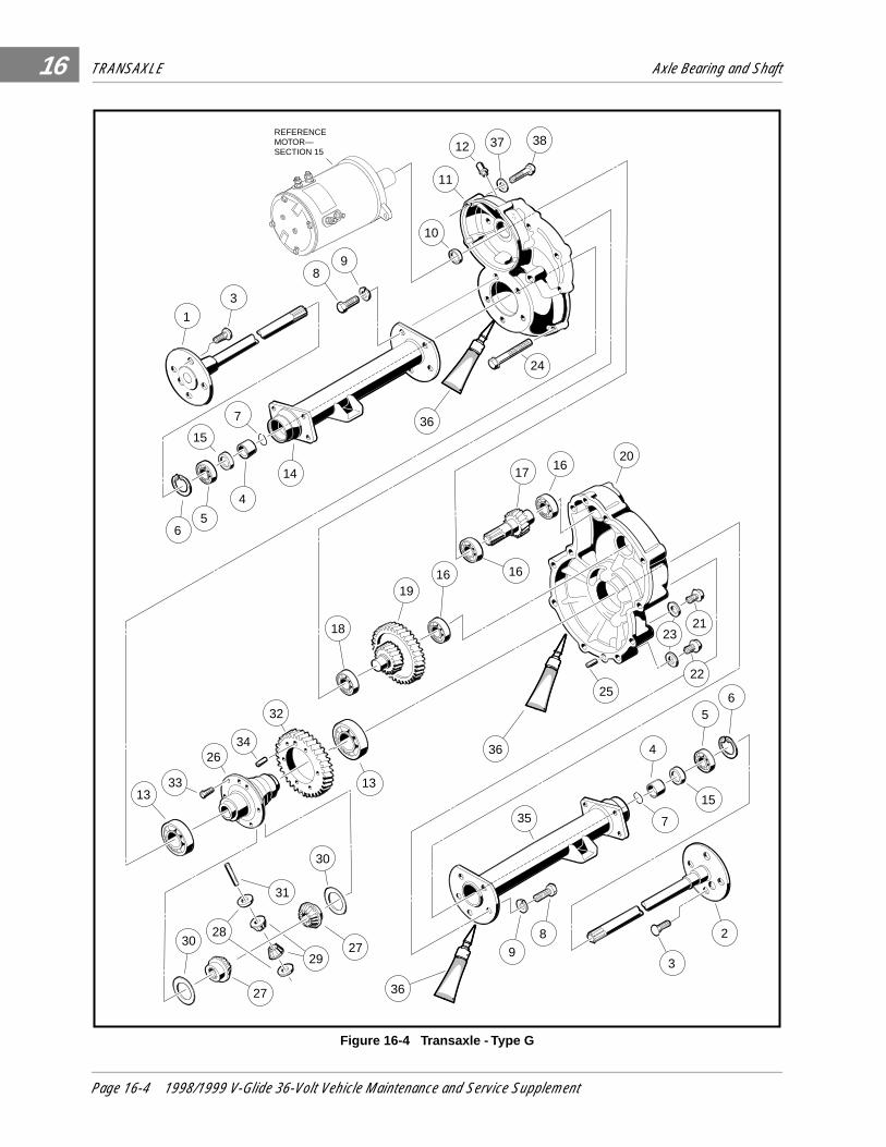
TRANSAXLE Axle Bearing and Shaft
16
Figure 16-4 Transaxle - Type G
12
25
20
65
15
4
735
2
3
89
18
1916 16
1617
1
3
89
10
11
37 38
4
14
7
15
56
2123
22
13
REFERENCEMOTOR—SECTION 15
24
2634
1333
36
36
36
32
27
30 27
30
31
29
28
Page 16-4 1998/1999 V-Glide 36-Volt Vehicle Maintenance and Service Supplement

TRANSAXLE Axle Bearing and Shaft
16
AXLE BEARING
Axle Bearing Removal (Type K Transaxle Only)1. Remove the retaining ring (7) from the axle shaft (Figure 16-3, Page 16-3) .
2. Place a bearing puller wedge attachment (Club Car Part No. 1012812) on the axle shaft between thewheel mounting flange and the bearing.
3. Press bearing (5) and collar (4) off together (Figure 16-6) . See following CAUTION and NOTE.
Figure 16-5 Seal Lip
• DO NOT REMOVE THE AXLE BEARING FROM A TYPE G TRANSAXLE. IF THE BEARING IS WORN,THE ENTIRE AXLE SHAFT ASSEMBLY (1 OR 2) MUST BE REPLACED (FIGURE 16-4, PAGE 16-4).
• DO NOT TIGHTEN THE BEARING PULLER WEDGE ATTACHMENT AGAINST THE AXLE SHAFT.THIS COULD DAMAGE THE AXLE SHAFT WHEN PRESSING OFF THE BEARING AND COLLAR.
• IT MAY BE NECESSARY TO HEAT THE COLLAR BEFORE THE COLLAR CAN BE REMOVED.
Figure 16-6 Bearing and Collar Figure 16-7 Axle Seal Tool
NOTE
CAUTION
NOTE
PRESS RAM
BEARINGPULLERWEDGEATTACHMENT
4
5
AXLE SEALTOOL
AXLE SEAL
1998/1999 V-Glide 36-Volt Vehicle Maintenance and Service Supplement Page 16-5

TRANSAXLE Axle Bearing and Shaft
16
Axle Bearing Installation (Type K Transaxles Only)1. If removed, place retaining ring (6) on axle shaft (1 or 2) (Figure 16-3, Page 16-3). The retaining ring
will be loose on the axle shaft until it is installed into the axle tube.
2. Apply two drops of Loctite® 271 to the inside of the collar. See following CAUTION.
3. Place the bearing and the collar on the shaft (note, this is a sealed bearing). See following CAUTION.
4. Place the bearing puller wedge attachment against the collar and, using a hydraulic press, press onboth the bearing and collar. See CAUTION on page 16-5.
5. Install retaining ring (7) into the groove on the axle shaft (Figure 16-3, Page 16-3) .
Axle Shaft and Oil Seal Installation1. Clean the bearing and seal seats in the axle tube (16 or 40) (Figure 16-3, Page 16-3) or (14 or 35)
(Figure 16-4, Page 16-4) .
2. Place a new seal (17) (Figure 16-3) or (15) (Figure 16-4) in the axle tube with the seal lip facing away fromthe bearing. Use an axle seal tool (Club Car Part No. 1014162) and mallet to tap it in until it seats firmly inposition (Figure 16-7, Page 16-5) . A hydraulic press may also be used with the axle seal tool.
3. Clean the shaft splines and then insert the shaft, splined end first, through the seal and into the axletube. Be careful not to damage the seal. Then advance the shaft through the inner bearing and rotate itto align the shaft splines with the splined bore of the differential side gear. Continue advancing the shaftuntil the bearing seats against the axle tube shoulder.
4. Using snap ring pliers, install retaining ring (6) inside axle tube (Figure 16-3 or 16-4, Page 16-3 or 16-4) .See following NOTE.
5. Place a 1/4 in. to 3/8 in. (6 to 10 mm) diameter rod against the retaining ring and tap lightly at four tofive locations around the retaining ring to ensure ring is properly seated. See following WARNING.
• APPLY LOCTITE 271® TO INSIDE OF COLLAR ONLY, NOT TO SHAFT, SO THAT THE LOCTITEWILL BE PUSHED AWAY FROM THE BEARING AS THE COLLAR AND BEARING ARE PRESSEDON. IF LOCTITE GETS ON OR IN THE BEARING, THE BEARING MUST BE REPLACED.
• THE COLLAR SHOULD BE REMOVED NO MORE THAN TWO TIMES. IF A BEARING ISREMOVED A THIRD TIME, THE SHAFT AND COLLAR WILL NOT GIVE A PROPER FIT.
• IF THE BEARING WAS REMOVED FROM THE SHAFT, REPLACE BEARING WITH A NEW ONE.
• TYPE G TRANSAXLES : IF RETAINING RING (6) MUST BE REPLACED, THE ENTIRE AXLESHAFT ASSEMBLY (1 OR 2) MUST BE REPLACED (FIGURE 16-4, PAGE 16-4).
• BE SURE THE RETAINING RING IS PROPERLY SEATED IN ITS GROOVE. IF THE RING IS NOTPROPERLY INSTALLED, THE AXLE ASSEMBLY WILL SEPARATE FROM THE TRANSAXLE ANDDAMAGE THE AXLE ASSEMBLY AND OTHER COMPONENTS. LOSS OF VEHICLE CONTROLCOULD RESULT, CAUSING SEVERE PERSONAL INJURY.
CAUTION
CAUTION
NOTE
WARNING
Page 16-6 1998/1999 V-Glide 36-Volt Vehicle Maintenance and Service Supplement

TRANSAXLE Transaxle
16
TRANSAXLE
Read DANGER and WARNING on page 16-1.
TRANSAXLE REMOVAL1. Place chocks at the front wheels and loosen the lug nuts on the rear wheels. Lift the rear of the vehicle
with a chain hoist or with a floor jack placed under the transaxle. Position jackstands under the framecross-member between the spring mount and the side stringer, just forward of each rear wheel. Lowerthe vehicle to let the jackstands support the vehicle (Figure 16-8, Page 16-7).
2. Remove the rear wheels, then thread one lug nut onto a stud on each rear hub. This will keep the brakedrums on the hubs.
3. Remove the cotter pins (1), brake cable clevis pins (2), and cable retaining E-clips (3). Disconnect thebrake cables (4) (Figure 16-9 ).
4. Disconnect the shock absorbers from their lower mounts (Figure 16-10) .
5. Disconnect the four motor wires. Use two wrenches to prevent the posts from turning.
6. With a floor jack supporting the transaxle, remove lower spring shackle nuts and bolts. Position shackles sothey are clear of springs (Figure 16-11) .
Figure 16-8 Support Vehicle on Jackstands Figure 16-9 Disconnect Brakes
Figure 16-10 Disconnect Shocks Figure 16-11 Shackles
1
2
4
3
DISCONNECT SHOCKABSORBERS FROMLOWER MOUNTS
REMOVE BOLTS, THENROTATE SHACKLESUP AND AWAYFROM SPRING
1998/1999 V-Glide 36-Volt Vehicle Maintenance and Service Supplement Page 16-7

TRANSAXLE Transaxle
16
Transaxle Removal, Continued:
7. If a chain hoist was used to raise the vehicle, lift the vehicle high enough to permit easy access andclearance for removal of the motor. If a floor jack was used to raise the vehicle, lower the transaxleenough to permit easy access and clearance for removal of the motor.
8. Remove the three motor mounting bolts (Figure 16-13, Page 16-8) and the motor positioning bolt (Fig-ure 16-14, Page 16-8) mounting the motor to the transaxle. See following WARNING.
9. Carefully remove the motor from the transaxle. Slide the motor away from the transaxle until the motorspline becomes disengaged from the input shaft, then lift motor out. See WARNING on page 16-7.
10. If a floorjack was used, pull floorjack from beneath the transaxle and allow the springs to rest on the floor.
11. Remove the U-bolts attaching the transaxle to the leaf springs (Figure 16-12, Page 16-8) .
12. Carefully lift each end of the transaxle off its positioning pin (on the leaf spring) and slide the transaxleto the rear and out of the vehicle.
13. Drain the lubricant from the transaxle and remove the axle shafts as instructed on page 16-2. See alsoNOTE on page 16-2.
14. If removal of the brake assemblies is required, see Section 6–Brakes in the Maintenance & Service Manual.
• DO NOT HOLD FINGERS UNDER MOTOR WHEN SLIDING MOTOR OFF INPUT SHAFT.FINGERS MAY GET PINCHED WHEN MOTOR DISENGAGES.
Figure 16-12 Leaf Springs Figure 16-13 Motor Mounting Bolts
Figure 16-14 Motor Positioning Bolt
WARNING
INTERMEDIATEGEAR ASSEMBLY
DIFFERENTIALGEAR CASE
MOTOR MOUNTINGBOLTS
INPUTPINIONGEAR
Page 16-8 1998/1999 V-Glide 36-Volt Vehicle Maintenance and Service Supplement

TRANSAXLE Transaxle Disassembly, Inspection and Assembly
16
TRANSAXLE DISASSEMBLY, INSPECTION AND ASSEMBLY
Read DANGER and WARNING on page 16-1.
TRANSAXLE DISASSEMBLY AND INSPECTION 1. To detach the axle tubes (16 and 40) (Figure 16-3, Page 16-3) or (14 and 35) (Figure 16-4, Page 16-4)
from the transaxle housing, remove the bolts and lock washers (8 and 9) (Figure 16-3 or 16-4) . See fol-lowing NOTE .
2. Remove 10 bolts (26) (Figure 16-3, Page 16-3) or 11 bolts, (24) (Figure 16-4, Page 16-4) holdinghousing together.
3. Pull the halves of the housing apart. If necessary, tap lightly on the spline of the input pinion.
4. Remove input pinion gear by pulling gear out while rocking intermediate gear assembly. Lift intermediate gearassembly and differential gear case unit out simultaneously (Figure 16-15).
5. Use a bearing puller or arbor press to remove bearings (18) (Figure 16-3, Page 16-3) or (16) (Figure16-4, Page 16-4) from the input pinion gear. If the oil seal (10) is damaged, replace it (Figures 16-3 or16-4, Pages 16-3 or 16-4) . See following CAUTION .
• TYPE K TRANSAXLES ONLY: SHIMS ARE LOCATED BETWEEN THE DRIVER SIDE AXLE TUBEAND DIFFERENTIAL CASE BEARING. DO NOT DAMAGE SHIMS. IF SHIMS ARE REMOVED, SETTHEM ASIDE FOR REINSTALLATION.
• TO PREVENT DAMAGE TO THE HOUSING MATING SEAL SURFACES, USE CAUTION WHENSEPARATING HALVES.
• DO NOT DAMAGE GEARS. USE EXTREME CARE WHEN HANDLING THEM.
Figure 16-15 Intermediate Gear Assembly Figure 16-16 Remove Key
• DO NOT REUSE BEARINGS AFTER REMOVING THEM. REPLACE BEARINGS WITH NEW ONES.
NOTE
CAUTION
CAUTION
ARBOR
PRESS RAMREMOVE KEY
CAUTION
1998/1999 V-Glide 36-Volt Vehicle Maintenance and Service Supplement Page 16-9

TRANSAXLE Transaxle Disassembly, Inspection and Assembly
16
Transaxle Disassembly and Inspection, Continued:6. To disassemble the intermediate gear assembly, press off together bearing (18) (Figure 16-3, Page 16-3) or
(16) (Figure 16-4, Page 16-4) and gear (23) (Figure 16-3, Page 16-3) or (19) (Figure 16-4, Page 16-4).See also Figure 16-15 .
7. Type K transaxles: Remove key (22) (Figure 16-3, Page 16-3). See also Figure 16-16, Page 16-9 .8. Press the bearing (20) (Figure 16-3, Page 16-3) or (18) (Figure 16-4, Page 16-4) off the intermediate
gear assembly.9. Disassemble the differential gear case:
9.1. Type K transaxles: Bend the bolt lock plates (29) down onto the ring gear (30) (Figure 16-3,Page 16-3). See also Figure 16-17, Page 16-10 .
9.2. Remove the eight hex bolts (28) (Figure 16-3, Page 16-3) or four hex bolts (33) (Figure 16-4,Page 16-4) that secure the ring gear to the differential case.
9.3. Remove the ring gear. Retain dowel pin from between the ring gear and differential case for reassembly.9.4. Separate the differential gear case housing. If necessary, reinstall two of the hex bolts (removed
previously in step 9.2.) into the differential gear unit and, while holding the unit slightly above thework area, lightly tap the bolt heads (Figure 16-18, Page 16-10) . Remove the two bolts.
9.5. Remove the differential pin (31) by pushing pin through differential gear case from one side (Fig-ures 16-3 or 16-4, Pages 16-3 or 16-4). See also Figure 16-19 .
9.6. Remove the idler gears and thrust plates (38 and 35), (Figure 16-3, Page 16-3) or (29 and 28)(Figure 16-4, Page 16-4) .
Figure 16-17 Lock Plate (Type K Only) Figure 16-18 Separate Housing
Figure 16-19 Differential Pin Figure 16-20 Left Differential
DOWEL PIN LOCK PLATE
TO SEPARATE HOUSING, IT MAY BE NECESSARY TO INSERT HEX HEAD BOLTS
INTO HOUSING ANDTAP LIGHTLY
DIFFERENTIALPIN
PUSH DIFFERENTIAL PIN THROUGHDIFFERENTIAL
GEAR CASE
THRUSTWASHER
SIDEGEAR
LEFTDIFFERENTIAL
GEARCASE
12
4
3
Page 16-10 1998/1999 V-Glide 36-Volt Vehicle Maintenance and Service Supplement
TRANSAXLE Transaxle Disassembly, Inspection and Assembly 16
9.7. Remove the differential gears and thrust plates (34 and 37) (Figure 16-3, Page 16-3) or (30 and27) (Figure 16-4, Page 16-4). See also Figure 16-20 .
9.8. Inspect the bearings (14) (Figure 16-3, Page 16-3) or (13) (Figure 16-4, Page 16-4) of the differ-ential case and replace them if they are damaged. To remove them, press them off. See CAU-TION at bottom of page 16-9.
10. Inspect all parts for wear or damage. Any worn or damaged parts should be replaced. See following NOTE.
TRANSAXLE ASSEMBLY
1. If bearings (14) (Figure 16-3, Page 16-3) or (13) (Figure 16-4, Page 16-4) were removed during disas-sembly, install new bearings using an arbor press.
2. Assemble the differential gear case.
2.1. Install the pin (31) (Figures 16-3 or 16-4, Pages 16-3 or 16-4) . Apply a small amount of oil to allthrust plates and to both ends of the pin.
• Type K transaxles:
2.2. While aligning the dowel pin, assemble the two halves of the differential gear case (33 and 36)and reinstall the output gear (30) (Figure 16-3, Page 16-3).
2.3. Install eight hex bolts (28) and the bolt lock plates (29) (Figure 16-3, Page 16-3) . Tighten the boltsto 18 ft.lb (24 N-m).
2.4. Bend the edges of the bolt locking tabs securely against the flats of the bolt heads to prevent thebolts from loosening and possibly causing damage (Figure 16-17, Page 16-10) .
2.5. If the large gear (23) was removed from the intermediate gear, insert key (22) into the keyway in the shaftand then press the large gear and the bearing (18) onto the shaft. Be sure the key is properly positionedin the keyway before attempting to press on the large gear and bearing (Figure 16-3, Page 16-3) .
• Type G transaxles:
2.6. Install four hex bolts (33) and output gear (32) (Figure 16-4, Page 16-4) . Tighten bolts to 51 ft.lb (69 N-m).
• All transaxles:
3. Press a new bearing (20) (Figure 16-3, Page 16-3) or (18) (Figure 16-4, Page 16-4) onto the interme-diate gear assembly.
4. Press new bearing (18) (Figure 16-3, Page 16-3) or (16) (Figure 16-4, Page 16-4) onto input pinion gear.
5. Apply grease to the lip of the new oil seal (10) (Figures 16-3 or 16-4, Pages 16-3 or 16-4) and installthe seal using a transaxle pinion seal tool (Club Car Part No. 1014161). The lip of the oil seal shouldface the inside of the transaxle housing. Make sure the seal is firmly seated.
6. Install the differential assembly, the intermediate gear assembly, and the input pinion gear simulta-neously. Be sure all bearings are seated properly in the housing. Rotate the input shaft to check forsmooth gear operation (Figure 16-13, Page 16-8) .
7. Install dowel pin (27) (Figure 16-3, Page 16-3) or (25) (Figure 16-4, Page 16-4) in the transaxle hous-ing (24 or 20) (Figures 16-3 or 16-4, Pages 16-3 or 16-4).
• DAMAGED OR WORN GEARS SHOULD BE REPLACED AS SETS.
• DO NOT PRESS AGAINST THE BEARING OUTER RACE.• TYPE K TRANSAXLES: GASKET FACES OF THE HOUSING MUST BE CLEAN AND SMOOTH.
USE ONLY A NEW GASKET (13) THAT IS NOT TORN OR DAMAGED. THE GASKET MUST LIEFLAT AGAINST THE HOUSING FACES (FIGURE 16-3, PAGE 16-3).
• THE HOUSING AND ALL PARTS MUST BE WIPED CLEAN AND DRY BEFORE REASSEMBLY.
NOTE
CAUTION
1998/1999 V-Glide 36-Volt Vehicle Maintenance and Service Supplement Page 16-11

TRANSAXLE Transaxle Disassembly, Inspection and Assembly16
Transaxle Assembly, Continued:8. Install left half of transaxle housing:
• For Type K transaxles:
8.1. Place a new gasket (13) (Figure 16-3, Page 16-3) in position on the mating face of the housing.Use the dowel pin to position the gasket. Make sure all holes are aligned.
8.2. Install left half of transaxle housing (24) (Figure 16-3, Page 16-3).
8.3. Install the ten bolts (26) and tighten to 69 in.lb (7.8 N-m) (Figure 16-3, Page 16-3).8.4. If the axle tube (16 and 40) was removed, install the shims (39), (if the shims were removed) and
a new gasket. Install the axle tube with five lock washers and bolts (9 and 8) (Figure 16-3, Page16-3). Tighten the bolts to 22 ft.lb (30 N-m).
• For Type G Transaxles:
8.1. Place 1/8 in. bead of three bond liquid gasket on mating face of housing. See following NOTE.
8.1. Install left half of transaxle housing (20) (Figure 16-4, Page 16-4).
8.1. Install eleven bolts in the case housing and tighten to 19 ft.lb (25.7 N-m). Type G transaxles have noshims or gasket.
8.2. Install axle tube with lock washers and bolts (9 and 8) (Figure 16-4, Page 16-4). Tighten the boltsto 36 ft.lb (49 N-m).
• For all transaxles:
9. Install the brake assemblies as instructed in Section 6–Brakes in the Maintenance & Service Manual.
10. Apply a small amount of grease to the lip of the oil seal (17) (Figure 16-3, Page 16-3) or (15) (Figure16-4, Page 16-4).
11. Clean the splines on the axle shaft assembly (1 and 2). Rotate the axle to align the shaft splines withthe splined bore of the differential side gear. Push the shaft in until the bearing seats against the shoul-der in the axle tube (Figures 16-3 and 16-4, Pages 16-3 and 16-4) .
12. Install the retaining ring (6) (Figures 16-3 and 16-4, Pages 16-3 and 16-4) in the axle tube. SeeWARNING on Page 16-6.
13. Make sure the drain plug is installed in the transaxle and tightened to 23 ft.lb (31 N-m). Fill the tran-saxle, through the level indicator hole, with 22 ounces of SAE 30 API Class SE, SF, or SG oil (a highergrade may also be used). Install and tighten the level indicator plug to 23 ft.lb (31 N-m).
SHIMMING THE TRANSAXLEType K Transaxles OnlyIf differential case (36 and 33), transaxle housing (11 and 24), or axle tube (16 and 40) has been replaced,transaxle may need new shims. To determine whether new shims are necessary, transaxle must be com-pletely assembled except for short axle tube (40) and both axle shafts (1 and 2) (Figure 16-3, Page 16-3) .
1. Stand the transaxle on end, on the axle tube.
• TYPE K TRANSAXLES: IF THE DIFFERENTIAL CASE (33 AND 36), THE TRANSAXLE HOUSING(11 AND 24) OR AXLE TUBE (16 AND 40) (FIGURE 16-3, PAGE 16-3) WAS REPLACED, SEESHIMMING THE TRANSAXLE ON PAGE 16-12.
• TYPE G TRANSAXLES DO NOT USE A GASKET ON THE MATING FACE OF THE HOUSING. USEAN 1/8 IN. BEAD OF THREE BOND LIQUID GASKET INSTEAD.
NOTE
NOTE
Page 16-12 1998/1999 V-Glide 36-Volt Vehicle Maintenance and Service Supplement

TRANSAXLE Transaxle Disassembly, Inspection and Assembly 16
2. Using a depth gauge, measure the distance from the gasket seal surface of the axle tube (gasket mustbe removed) to the outer race of the bearing (14) on the differential case (33) (Figure 16-3, Page 16-3) .See also Figure 16-21 .
3. Use the following chart to determine whether shimming is required and, if so, how many shims (ClubCar Part No. 1013781) should be used.
TRANSAXLE INSTALLATION1. If using a chain hoist, raise the vehicle and place transaxle in position on the jackstands. If using a floor
jack, lower the jackstands to their lowest settings and place the transaxle in position on the jackstands.See DANGER and WARNING on page 16-1.
2. Align the center hole in the saddle of the transaxle with the pilot bolt in the leaf spring assembly.
3. Install the two U-bolts, lockwashers, and nuts. Tighten the nuts to 25 ft.lb (34 N-m). Tighten the U-boltnuts so an equal amount of thread is visible on each leg of the bolt.
4. Install motor. See Motor–Section 15.
5. If using a chain hoist, lower the vehicle while guiding the leaf springs into the rear spring shackles. Ifusing a floor jack, raise the differential while guiding the leaf springs into the rear spring shackles. Thenraise the jackstands to support the transaxle.
6. Reconnect the four motor wires. When tightening the retaining nuts, use two wrenches to prevent themotor studs from turning. See following NOTE.
Distance from gasket seal surfaceto outer race or bearing -
INCHES (MM)
SHIMSREQUIRED
Up to .134 inches (3.4 mm) 0
.134 - .142 inches (3.4 - 3.6 mm) 1
.142 - .150 inches (3.6 - 3.8 mm) 2
.150 - .155 inches (3.8 - 3.9 mm) 3
Figure 16-21 Depth Gauge
• IF THE MOTOR WIRES WERE NOT TAGGED WHEN DISCONNECTED, SEE SECTION 11,FIGURE 11-3, PAGE 11-4, VEHICLE WIRING DIAGRAM FOR PROPER CONNECTIONS.
110
20 30
4050
607080
90
NOTE
1998/1999 V-Glide 36-Volt Vehicle Maintenance and Service Supplement Page 16-13

TRANSAXLE Transaxle Disassembly, Inspection and Assembly16
Transaxle Installation, Continued:7. Insert bolts through the spring shackles and bushings in the leaf spring eyes. Secure bolts with lock nuts.
8. Connect the brake cables.
9. Install the shock absorbers. Tighten shock absorber retaining nuts until the rubber bushings expand tothe same size as the cup washers.
10. Install the rear wheels and finger tighten the lug nuts.
11. Lift the vehicle and remove the jackstands. Lower vehicle and tighten rear wheel lug nuts (using a criss-cross pattern) to 55 ft.lb (74.6 N-m).
12. Test drive the vehicle to check for proper operation.
Page 16-14 1998/1999 V-Glide 36-Volt Vehicle Maintenance and Service Supplement


Golf CarsClub Car Inc.P.O. Box 204658Augusta, GA 30917-4658


