67
AIR FORCE HANDBOOK 10-222, Volume 5 1 October 1998 GUIDE TO BARE BASE POWER PLANT INSTALLATION WWW.SURVIVALEBOOKS.COM
| Date post: | 04-Jun-2018 |
| Category: |
Documents |
| Upload: | lo-shun-fat |
| View: | 217 times |
| Download: | 0 times |

8/13/2019 1998 Us Air Force Guide to Bare Base Power Plant Installation 67p
http://slidepdf.com/reader/full/1998-us-air-force-guide-to-bare-base-power-plant-installation-67p 1/67
AIR FORCE HANDBOOK 10-222, Volume 5
1 October 1998
GUIDE TO BARE BASE POWER
PLANT INSTALLATION
WWW.SURVIVALEBOOKS.COM

8/13/2019 1998 Us Air Force Guide to Bare Base Power Plant Installation 67p
http://slidepdf.com/reader/full/1998-us-air-force-guide-to-bare-base-power-plant-installation-67p 2/67
WWW.SURVIVALEBOOKS.COM

8/13/2019 1998 Us Air Force Guide to Bare Base Power Plant Installation 67p
http://slidepdf.com/reader/full/1998-us-air-force-guide-to-bare-base-power-plant-installation-67p 3/67
BY ORDER OF THE AIR FORCE HANDBOOK 10-222, VOLUME 5
SECRETARY OF THE AIR FORCE 1 OCTOBER 1998
Operations
GUIDE TO BARE BASE POWER PLANT
INSTALLATION ___________________________________________________________________
NOTICE: This publication is available digitally on the SAF/AAD WWW site at:
http://afpubs.hq.af.mil. If you lack access, contact your Publishing DistributionOffice (PDO).
OPR: HQ AFCESA/CEXR (Major Gregory A. Cummings)
Certified by: HQ AFCESA/CEX (Colonel Bruce F. Mc Connell)
Pages 65/Distribution: F
This handbook is designed to assist you in establishing a power plant
network at a bare base or remote location. It discusses in a generic sense
bare base power requirements, site selection and layout, primary electrical
connections, safety considerations, and basic maintenance and emergency
planning requirements. When coupled with information contained in
AFPAM 10-219, Vol 5, Bare Base Conceptual Planning Guide, and
instruction received at Silver Flag training sites, electrical and power
production personnel should be capable of effectively setting up a bare base
primary power generation system.
INTRODUCTION ............. ............. ............. ............. ............. ............. ........5
REQUIREMENTS AND OPERATIONAL FEATURES........... ............. .....6
TOOLS, EQUIPMENT AND SAFETY ............ ............. ............. ............. .21
SITE SELECTION AND LAYOUT ............. ............. ............. ............. .....31
CONNECTIONS ............. ............. ............. ............. ............. ............. ........44
MAINTENANCE AND EMERGENCY PLANNING............... ............. ...63
Figures
1. Harvest Falcon Electrical Assets....................................................5
2. Taps On A Secondary Distribution Center...................................17
3. Typical Power Plant Layouts .......................................................19
4. Use of Rubber Gloves During Electrical System Maintenance. ....21
WWW.SURVIVALEBOOKS.COM

8/13/2019 1998 Us Air Force Guide to Bare Base Power Plant Installation 67p
http://slidepdf.com/reader/full/1998-us-air-force-guide-to-bare-base-power-plant-installation-67p 4/67
AFH 10-222 Volume 5 1 October 1998 2
5. Air Testing of Rubber Gloves......................................................22
6. Visual Inspection of Rubber Gloves.............................................23
7. Using Hot Sticks To Close Protective Switching Devices.............24
8. Grip-All Clamp Stick..................................................................25
9. Burying Of Electrical Cables.......................................................27
10. Harvest Falcon Trencher .............................................................28
11. Typical Bare Base Power Plant....................................................31
12. Movement of Power Plant Assets.................................................33
13. 750-kW Generator ......................................................................34
14. Typical Generator Layout............................................................3515. Primary Distribution Center........................................................36
16. Typical PDC Location .................................................................36
17. Fuel Bladder Supporting 750-kW Generator................................38
18. Fuel Bladder Placement...............................................................38
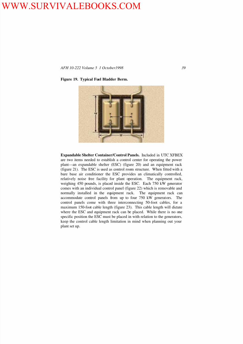
19. Typical Fuel Bladder Berm .........................................................39
20. Expandable Shelter Container.....................................................40
21. Equipment Rack..........................................................................40
22. 750-kW Generator Control Panel ................................................41
23. Control Panel Cable ....................................................................41
24. Remote Area Lighting Set ...........................................................42
25. Typical Vertical Ground Rod Installation ....................................45
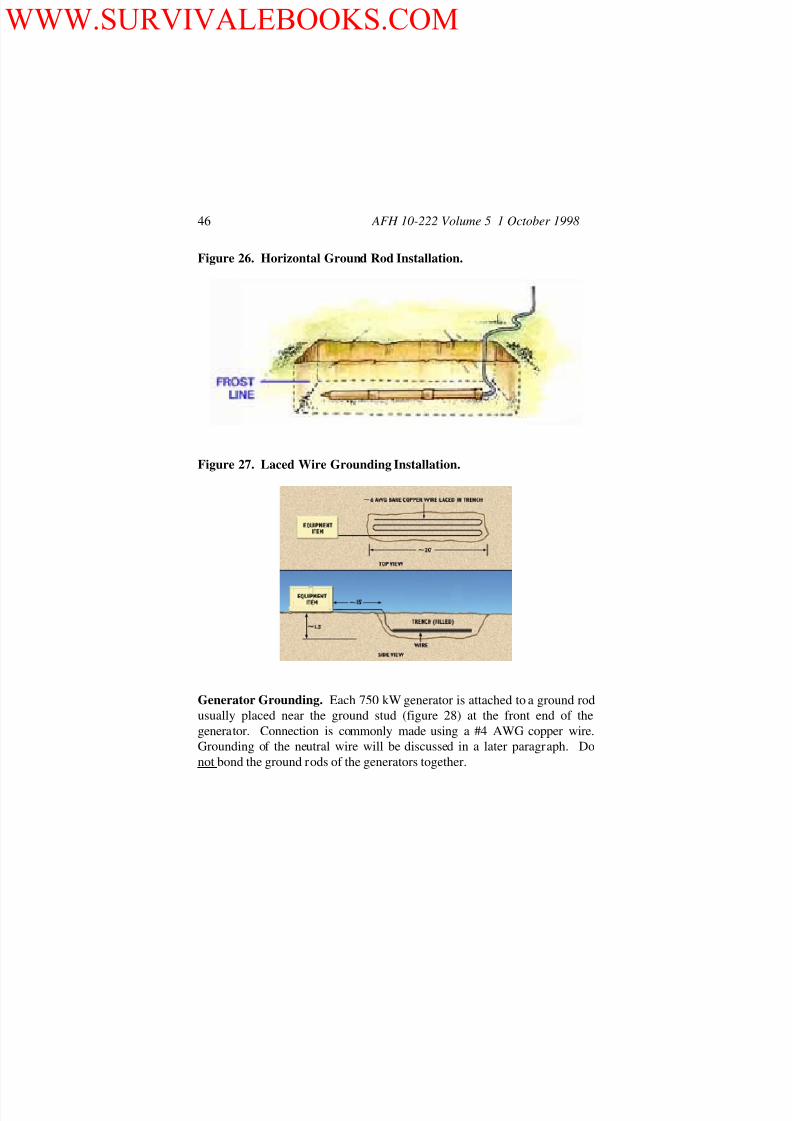
26. Horizontal Ground Rod Installation.............................................46
27. Laced Wire Grounding Installation .............................................46
28. 750-kW Generator Ground Stud..................................................47
29. PDC Ground Rod Installation......................................................47
30. Grounding Connection For An SDC............................................48
31. Cable Skids.................................................................................49
32. Load Break Elbow.......................................................................50
33. Black, Red and Blue Marking Of Primary Cables........................50
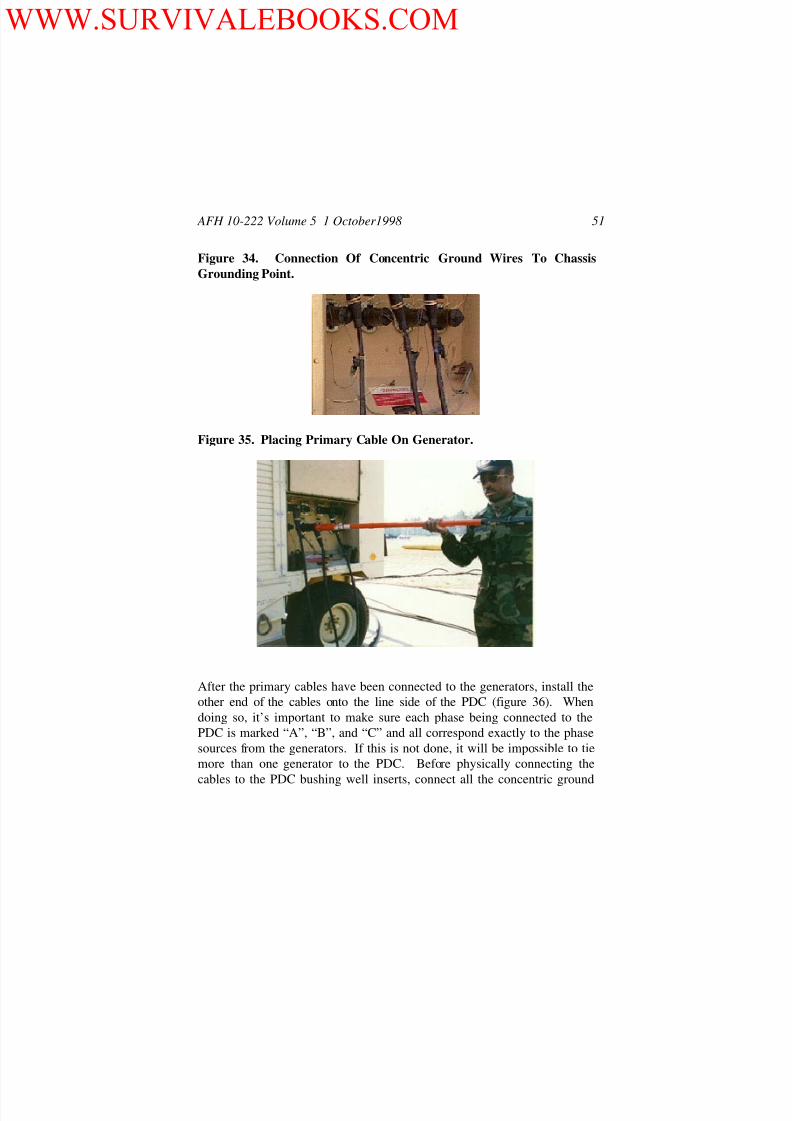
34. Connection Of Concentric Ground Wires To Chassis
Grounding Point .........................................................................51
35. Placing Primary Cable On Generator ..........................................51
36. Primary Cable PDC Line Side Connection ..................................52
37. Connection Of Concentric Ground Wires On Line Side Of PDC .53
38. Connection Of Concentric Grounds On Load Side Of PDC .........54
WWW.SURVIVALEBOOKS.COM

8/13/2019 1998 Us Air Force Guide to Bare Base Power Plant Installation 67p
http://slidepdf.com/reader/full/1998-us-air-force-guide-to-bare-base-power-plant-installation-67p 5/67
AFH 10-222 Volume 5 1 October1998 3
39. PDC Load Side Feeder Connections ............................................54
40. PDC With Arc Strangler Switches Removed From Unused
Feeders........................................................................................55
41. High Voltage Input Cables Connected To SDC Bushings............56
42. Removal Of Electric Fusible Disconnect Switch Center Pole .......56
43. Concentric Ground Wire Connection At SDC .............................57
44. Input And Output Cables On An SDC.........................................58
45. Control Panel Cables Leaving Generator .....................................59
46. Fuel Storage Bladder...................................................................60
47. Fuel System Manifold .................................................................6048. Fuel Hose Connected To 750-kW Generator................................61
49. Power Plants Interconnected Through SDCs ...............................62
Tables
1. Harvest Falcon Deployment Packages ...........................................6
2. Harvest Falcon Power Generation And Distribution Assets............7
3. Connected Load Table ................................................................11
4. Demand Factors ..........................................................................15
5. Task Responsibilities ..................................................................20
6. Harvest Falcon Electrical System Technical Orders.....................63
WWW.SURVIVALEBOOKS.COM

8/13/2019 1998 Us Air Force Guide to Bare Base Power Plant Installation 67p
http://slidepdf.com/reader/full/1998-us-air-force-guide-to-bare-base-power-plant-installation-67p 6/67
AFH 10-222 Volume 5 1 October 1998 4
THIS PAGE INTENTIONALLY LEFT BLANK.
WWW.SURVIVALEBOOKS.COM

8/13/2019 1998 Us Air Force Guide to Bare Base Power Plant Installation 67p
http://slidepdf.com/reader/full/1998-us-air-force-guide-to-bare-base-power-plant-installation-67p 7/67
AFH 10-222 Volume 5 1 October1998 5
INTRODUCTION
GUIDE TO BARE BASE POWER PLANT
INSTALLATION
PURPOSE OF HANDBOOK
This handbook addresses the actions necessary to establish a primary power
generation system at a bare base location using existing Harvest Falcon
electrical assets (figure 1). It is meant to be used by civil engineering power
production and electrical personnel responsible for installation, operations
and maintenance of the bare base electrical system. Users of this booklet
are assumed to have a basic knowledge of bare base assets and their use—
readers without this fundamental knowledge should review AFPAM 10-
219, Volume 5, Bare Base Conceptual Planning Guide; AFH 10-222,
Volume 1, Guide To Bare Base Development; and AFH 10-222, Volume 2,
Guide To Bare Base Assets.
Figure 1. Harvest Falcon Electrical Assets.
WWW.SURVIVALEBOOKS.COM
8/13/2019 1998 Us Air Force Guide to Bare Base Power Plant Installation 67p
http://slidepdf.com/reader/full/1998-us-air-force-guide-to-bare-base-power-plant-installation-67p 8/67
AFH 10-222 Volume 5 1 October 1998 6
REQUIREMENTS AND
REQUIREMENTS AND
OPERATIONAL FEATURES
Planning Factors
In the Harvest Falcon system much of the electrical planning is
“preordained” by the quantities of electrical assets contained in the various
deployment sets. Assuming the engineer and logistics planners on the
Unified and Component Command staffs have properly identified HarvestFalcon needs, sufficient assets should flow into a beddown location.
Deployed engineer personnel essentially set up the electrical equipment
items when they are received and do not normally have to be concerned
with whether generation capacity will satisfy base demands.
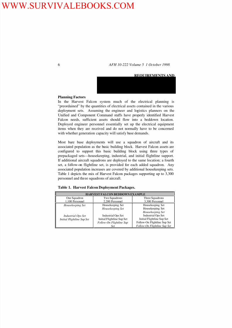
Most bare base deployments will use a squadron of aircraft and its
associated population as the basic building block. Harvest Falcon assets are
configured to support this basic building block using three types of
prepackaged sets—housekeeping, industrial, and initial flightline support.
If additional aircraft squadrons are deployed to the same location; a fourth
set, a follow-on flightline set, is provided for each added squadron. Any
associated population increases are covered by additional housekeeping sets.
Table 1 depicts the mix of Harvest Falcon packages supporting up to 3,300
personnel and three squadrons of aircraft.
Table 1. Harvest Falcon Deployment Packages.
HARVEST FALCON BEDDOWN EXAMPLE
One Squadron
1,100 Personnel
Two Squadrons
2,200 Personnel
Three Squadrons
3,300 Personnel
Housekeeping Set
Industrial Ops Set
Initial Flightline Sup Set
Housekeeping Set
Housekeeping Set
Industrial Ops Set
Initial Flightline Sup Set
Follow-On Flightline Sup
Set
Housekeeping Set
Housekeeping Set
Housekeeping Set Industrial Ops Set
Initial Flightline Sup Set
Follow-On Flightline Sup Set
Follow-On Flightline Sup Set
WWW.SURVIVALEBOOKS.COM

8/13/2019 1998 Us Air Force Guide to Bare Base Power Plant Installation 67p
http://slidepdf.com/reader/full/1998-us-air-force-guide-to-bare-base-power-plant-installation-67p 9/67
AFH 10-222 Volume 5 1 October1998 7
Within these deployment packages are contained various quantities of the
electrical system assets necessary to establish the base’s electrical power
generation and distribution network. Types and quantities of major
components used in the power plant set up are shown in table 2. Note that
these items are included in the housekeeping and industrial operations
packages. There are also electrical assets (primarily secondary distribution
centers (SDC)) contained in the flightline sets but these generally pertain to
the distribution system rather than power generation. While the
housekeeping and industrial operations sets should normally be among the
first packages to arrive at a bare base, be aware that there are many aircraftsorties required to move these two packages in and electrical components
account for only a fraction of the total items moved. You will likely not see
all electrical components arrive at the same time. The quantities of cable
skids and remote area light sets shown in table 2 are meant to serve the
entire generation and distribution system, not just the power plant(s).
Table 2. Harvest Falcon Power Generation and Distribution Assets.
Asset Type Prepackaged Set
Housekeeping Industrial Operations
750-kW Generator 4 1
Primary Distribution Center 2
Cable Skids 6
Fuel Bladders 2 1
Expandable Shelter Container 1
Remote Area Light Set 6
Equipment Rack 1
The basic planning factors used in developing the Harvest Falcon electrical
package were 1.5 kW per person for the housekeeping set raising to 2.7 kW
per person when the industrial and flightline packages were added. If you
are faced with expanding the electrical system on your installation, these
same planning factors can be used as a starting point. Once you have
calculated the potential added load, you can request additional Harvest
Falcon assets to be shipped in. Most Falcon electrical components can be
WWW.SURVIVALEBOOKS.COM

8/13/2019 1998 Us Air Force Guide to Bare Base Power Plant Installation 67p
http://slidepdf.com/reader/full/1998-us-air-force-guide-to-bare-base-power-plant-installation-67p 10/67
AFH 10-222 Volume 5 1 October 1998 8
requested singularly. For example, unit type code (UTC) XFBE7 contains
one 750 kW generator and XFBEF contains one primary distribution center.
See AFH 10-222, Volume 2, Annex F for additional UTCs.
Basic Concepts
Before you begin work it is important to brush up on some basic
fundamentals. The current required by induction motors, transformers and
any other device consists of two separate components: magnetizing current
and power-producing current . This concept of two types of current is
particularly helpful in understanding what power factor is and the problemsassociated with low power factors. Power-producing current is converted by
the equipment into work. This working power is measured in kilowatts
(kW). Magnetizing current is required by the equipment to produce the
magnetic flux necessary for operation of all inductive devices. This is
referred to as reactive power and is measured in kilovolt-amperes-reactive
(KVAR). Total current is what would be read on an ammeter, and has both
a reactive and working component. The unit of measurement of this
apparent power is the kilovolt-ampere (KVA).
Power Factor
You should also be aware of what power factor is as well as the influence it
has on your power generating system. Power factor is the relationship
between working (active) power and total power consumed (apparent
power). Essentially, power factor is a measurement of how effectively
electrical power is being used. The higher the power factor, the more
effectively electrical power is being used and vice versa.
The Harvest Falcon distribution system’s operating power is composed of
two parts: Active (working) power and reactive (non-working magnetizing)
power. The ACTIVE power performs the useful work….the REACTIVE
power does not. Its only function is to develop magnetic fields required by
inductive devices.
A great deal of equipment utilized in the Harvest Falcon set as well as unit
and personal equipment people bring with them during a deployment cause
WWW.SURVIVALEBOOKS.COM

8/13/2019 1998 Us Air Force Guide to Bare Base Power Plant Installation 67p
http://slidepdf.com/reader/full/1998-us-air-force-guide-to-bare-base-power-plant-installation-67p 11/67
AFH 10-222 Volume 5 1 October1998 9
poor generating plant power factor. One of the worst offenders is the lightly
loaded induction motor. Generally, the power factor at the power plant
decreases with increased motor (reactive power) loads. Therefore when
more inductive reactive power is produced, more apparent power is also
needed to compensate. Because of the inductive reactance placed in the
system by air conditioner compressor and fan motors, fluorescent light
ballasts, and lightly loaded SDC transformers; the system power factor often
ranges between 0.70 and 0.90. At some locations during the Gulf War, the
power factor of the Harvest Falcon electrical system dropped as low as 0.45
and averaged only 0.68. The effect of the power factor on your generationcapability could be substantial. The lower the power factor the more
generation capacity is needed to support a given load. For example, if your
power factor is 0.70 to support a load of 100 kW (real power), you will need
to generate 143 KVA (apparent power). Unless you have the ability to add
capacitor banks (not part of Harvest Falcon equipage) to your system or
capacitors to your inductive devices, this power factor effect must be
considered when planning and establishing power plants. Use a power
factor of 0.80 as a starting point for planning activities.
Removing system KVAR improves the power factor. Improving the power
factor releases system capacity and permits additional loads to be added
without overloading the system. As power factor increases, KVAR
decreases better utilizing the electrical power you’re producing. For
example, in a typical system with a 0.80 power factor, 800 kW of real power
is available for the load while 1,000 KVA of apparent power is being
generated. By correcting the system to unity (1.0 power factor), the kW will
equal the KVA. Now your system will support 1,000 kW, versus the 800
kW at the 0.80 power factor; an increase of 200 kW of productive power.
Layout of Distribution System
Now it is time to go to work. Draw a rough layout of your Harvest Falcon
electrical distribution system showing the location of generators, primary
distribution centers (PDCs), and SDCs. In laying out the system, your chief
concern will be supplying electric energy at voltages necessary to operate
the consuming equipment. Electric power from host nation sources is used
WWW.SURVIVALEBOOKS.COM

8/13/2019 1998 Us Air Force Guide to Bare Base Power Plant Installation 67p
http://slidepdf.com/reader/full/1998-us-air-force-guide-to-bare-base-power-plant-installation-67p 12/67
AFH 10-222 Volume 5 1 October 1998 10
if available, unless inadequate or subject to frequent interruption. On
deployments where it is not possible to connect to host nation commercial
sources, bare base generators are used.
Load Estimation
The entire layout of the distribution depends on load estimation. Load
estimation covers both location of the load and magnitude of the load.
Location of the Load. To estimate the load, first obtain a rough drawing or
layout of the designated area for beddown of the force. Now locate on it
where you plan to set up your generating plant(s) and mark the various
facilities to be connected to the distribution system. Identify each shelter,
such as billeting tents, command posts, warehouses, and shops.
Determining Magnitude of Load. If time permits, you should take the
extra effort to be more precise in determining your electrical requirements
by applying demand and diversity factors. Application of these factors
provides a closer estimate of actual potential load on a power plant. From a
bare base perspective this could prevent shipping in redundant equipment
and free airlift sorties for other important bare base support items.
The starting point for your load determination should be calculating theconnected load on the system. The connected load is the sum of the rated
capacities of all electrical appliances, lamps, motors, etc., connected to all
the circuits of the system. Many times this data can be found on name
plates of motors, air conditioners, and electrical equipment. If time does
not permit or you do not have access to the data, you can use table 3 as a
guide for determining connected loads.
WWW.SURVIVALEBOOKS.COM

8/13/2019 1998 Us Air Force Guide to Bare Base Power Plant Installation 67p
http://slidepdf.com/reader/full/1998-us-air-force-guide-to-bare-base-power-plant-installation-67p 13/67
AFH 10-222 Volume 5 1 October1998 11
Table 3. Connected Load Table.
Type of Facility
Basic Function
Connected Power
(KVA)
Connected Air Conditioners
(KVA)
Temper/Admin/Command 5.7 10
Temper/Billets 4.5 10
ESC/Power Plant 5.8 10
GP/Warehousing 6.9 20
Temper/ 9-1Kitchen 100 40
Temper/Shower-Shave 6.0
Temper/Latrine 6.0
Temper/Laundry 10 10
ESC/Avionics Shop 15 10
GP/Avionics Shop 15 20
Temper/Engr Util Shop 5.8 10
Temper/Engr Struct Shop 11.6 10
Temper/Engr HVAC Shop 7.8 10
Temper/Engr Elect Shop 7.3 10
Temper/Engr Fuels Shop 7.2 10
GP/Engr Power Pro Shop 9.7 20
GP/Engr Equip Shop 6.9 20
ESC/Pneudraulics Shop 28.1 10
ESC/NDI Shop 7.7 10
FSTFS/Propulsion Shop 36
GP/Propulsion Shop 15 20
ESC/Elect Shop 15.6 10
ESC/Bearings Shop 5.8 10
GP/AGE Shop 8.2 20
ESC/Parachute Shop 6.6 10
ACH/Hanger 36
ESC/Wheel/Tire Shop 6.0 10
WWW.SURVIVALEBOOKS.COM

8/13/2019 1998 Us Air Force Guide to Bare Base Power Plant Installation 67p
http://slidepdf.com/reader/full/1998-us-air-force-guide-to-bare-base-power-plant-installation-67p 14/67
AFH 10-222 Volume 5 1 October 1998 12
Type of Facility
Basic Function
Connected Power
(KVA)
Connected Air Conditioners
(KVA)
GP/Gen Maint Shop 10 20
ESC/Gen Maint Shop 8.0 10
Temper/Sqd Ops 5.9 10
ESC/Life Support Shop 5.7 10
GP/Sqd Ops Support Shop 6.5 20
Temper/Base Admin 5.6 10
Temper/Post Office 3.9 10Temper/Legal Office 4.9 10
Temper/BX 6.0 10
ESC/BX 8.0 10
GP/Gen Support 7.0 20
Temper/MWRS 4.6 10
ESC/Comm Facility 9.0 10
ESC/Armory 4.5 10
ESC/SRC 4.5 10
Temper/Fire Ops 4.5 10
Temper/Fire Tech Svs 5.0 10
Temper/Security Force 4.5 10
Temper/EOD 6.2 10Temper/Base Ops 4.5 10
Temper/Engr Readiness 4.5 10
Temper/Mortuary 6.3 10
Temper/Aerial Port 4.5 10
GP/Aerial Port 6.5 20
GP/Munitions Maint 8.2 20
ESC/POL Lab 4.5 10
Temper/Alert Facility 5.4 10
ESC/Supply Processing 5.1 10
FSTFS/Supply Storage 10
Temper/Vehicle Ops 4.5 10
Temper/TMO 4.5 10
WWW.SURVIVALEBOOKS.COM

8/13/2019 1998 Us Air Force Guide to Bare Base Power Plant Installation 67p
http://slidepdf.com/reader/full/1998-us-air-force-guide-to-bare-base-power-plant-installation-67p 15/67
AFH 10-222 Volume 5 1 October1998 13
Type of Facility
Basic Function
Connected Power
(KVA)
Connected Air Conditioners
(KVA)
FSTFS/Vehicle Maint 18.5
FSTFS/Packing/Crating 12.0
Temper/Briefing 7.0 10
Temper/Ops/Plans 4.6 10
Temper/Intel 5.6 10
Temper/Maint/Job Cont 4.8 10
Temper/Maint Mat Cont 6.3 10Temper/Maint QC 6.3 10
ESC/Intel 5.6 10
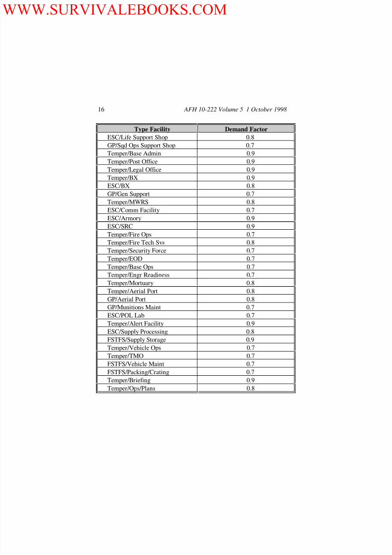
A connected load must be converted to a demand load. Demand is the
maximum KVA required to serve a given connected load. Demand is less
than connected load because all connected equipment seldom is operating
simultaneously. The ratio between demand and connected load is the
demand factor. Therefore, the demand factor is usually less than 1.0. Your
more senior power production personnel should be able to provide realistic
estimation of the demand factor for various facilities based on the mission
of the facilities and what electrical equipment is installed. Table 4 can also
be used as a guide for determining demand loads. Compute the demand for
each facility and record it on your layout drawing at the proper location
(multiply connected load estimate by demand factor). This data could prove
invaluable if demand loads increase beyond the capacity of the number of
generators provided in your Harvest Falcon set and you must request
additional support. Once beddown operations are complete, it is advisable
to take actual demand readings at each facility. These more accurate data
should be recorded so that they will be available in the case of a future base
expansion.
Diversity Factor
Once demand loads on all facilities and supporting equipment items are
identified, the maximum demand of all facilities as a whole is determined.
The maximum demand of all facilities as a group is less than the sum of the
WWW.SURVIVALEBOOKS.COM

8/13/2019 1998 Us Air Force Guide to Bare Base Power Plant Installation 67p
http://slidepdf.com/reader/full/1998-us-air-force-guide-to-bare-base-power-plant-installation-67p 16/67
AFH 10-222 Volume 5 1 October 1998 14
individual facility demands. This is true because at no time would the
lights, appliances or motors in all the facilities be used at exactly the same
time. The maximum demand of all facilities as a group is calculated by
applying a diversity factor against the demand load of individual facilities
and totaling the resultant figures. Like the demand factor, the diversity
factor is based on experience and is usually less than 1.0. The Harvest
Falcon electrical system was built using a diversity factor of 0.7. An
indication of a diversity factor to use at your location could be obtained from
power plant logs. The ratio obtained when comparing average daily peak
KVA against the total of the individual facility demands should provide aninitial estimate. Use common sense when applying the diversity factor,
however. It should not be applied to those equipment items that would
likely operate in unison, for example, air conditioning units. In developing
the Harvest Falcon system, the demand load for air conditioners was left at
100% rather than being reduced using the 0.7 diversity factor. Once you
have applied the demand and diversity factors to the connected load at your
installation, you should have a relatively realistic idea of the power plant
requirement.
Voltage Drop and Regulation
Even though the Harvest Falcon electrical system is normally set up as a looped
network, voltage drop will occur, primarily through line loss from impedance.
Voltage drop in a system has a detrimental effect on equipment and resistance-typedevices. Motors run with less efficiency and tend to overheat and lighting becomes
dimmer or may not work at all in the case of fluorescents. To reduce the effects of
voltage drop on lighting and equipment, primary runs should be kept to 4000 feet or
less and secondary circuit runs limited to 800 feet or less if possible. The 4000 feet
primary run assumes load concentrated at end of circuit. If load is evenly spaced
along the run, the run can go up to approximately 1.5 miles. The transformer taps
on secondary distribution centers (figure 2) also can be used to adjust for voltage
drop. Several tap settings (two for high voltage, four for low voltage) exist on the
primary side of an SDC permitting the secondary voltage to be maintained relatively
steady. Changing the tap settings, however, is not a quick task. You will have
to remove panels from the SDC and rewire the tap connections.
WWW.SURVIVALEBOOKS.COM

8/13/2019 1998 Us Air Force Guide to Bare Base Power Plant Installation 67p
http://slidepdf.com/reader/full/1998-us-air-force-guide-to-bare-base-power-plant-installation-67p 17/67
AFH 10-222 Volume 5 1 October1998 15
Table 4. Demand Factors.
Type Facility Demand Factor
Temper/Admin/Command 0.9
Temper/Billets 1.0
ESC/Power Plant 1.0
GP/Warehousing 0.6
Temper/ 9-1Kitchen 0.9
Temper/Shower-Shave 0.9
Temper/Latrine 0.8
Temper/Laundry 0.9
ESC/Avionics Shop 0.7
GP/Avionics Shop 0.7
Temper/Engr Util Shop 0.6
Temper/Engr Struct Shop 0.6
Temper/Engr HVAC Shop 0.6
Temper/Engr Elect Shop 0.6
Temper/Engr Fuels Shop 0.6
GP/Engr Power Pro Shop 0.6
GP/Engr Equip Shop 0.6
ESC/Pneudraulics Shop 0.7
ESC/NDI Shop 0.7
FSTFS/Propulsion Shop 0.8
GP/Propulsion Shop 0.7
ESC/Elect Shop 0.7
ESC/Bearings Shop 0.7
GP/AGE Shop 0.7
ESC/Parachute Shop 0.8
ACH/Hanger 0.9
ESC/Wheel/Tire Shop 0.7
GP/Gen Maint Shop 0.8
ESC/Gen Maint Shop 0.7
Temper/Sqd Ops 0.9
WWW.SURVIVALEBOOKS.COM
8/13/2019 1998 Us Air Force Guide to Bare Base Power Plant Installation 67p
http://slidepdf.com/reader/full/1998-us-air-force-guide-to-bare-base-power-plant-installation-67p 18/67
AFH 10-222 Volume 5 1 October 1998 16
Type Facility Demand Factor
ESC/Life Support Shop 0.8
GP/Sqd Ops Support Shop 0.7
Temper/Base Admin 0.9
Temper/Post Office 0.9
Temper/Legal Office 0.9
Temper/BX 0.9
ESC/BX 0.8
GP/Gen Support 0.7Temper/MWRS 0.8
ESC/Comm Facility 0.7
ESC/Armory 0.9
ESC/SRC 0.9
Temper/Fire Ops 0.7
Temper/Fire Tech Svs 0.8
Temper/Security Force 0.7
Temper/EOD 0.7
Temper/Base Ops 0.7
Temper/Engr Readiness 0.7
Temper/Mortuary 0.8
Temper/Aerial Port 0.8GP/Aerial Port 0.8
GP/Munitions Maint 0.7
ESC/POL Lab 0.7
Temper/Alert Facility 0.9
ESC/Supply Processing 0.8
FSTFS/Supply Storage 0.9
Temper/Vehicle Ops 0.7
Temper/TMO 0.7
FSTFS/Vehicle Maint 0.7
FSTFS/Packing/Crating 0.7
Temper/Briefing 0.9
Temper/Ops/Plans 0.8
WWW.SURVIVALEBOOKS.COM

8/13/2019 1998 Us Air Force Guide to Bare Base Power Plant Installation 67p
http://slidepdf.com/reader/full/1998-us-air-force-guide-to-bare-base-power-plant-installation-67p 19/67
AFH 10-222 Volume 5 1 October1998 17
Type Facility Demand Factor
Temper/Intel 0.8
Temper/Maint/Job Cont 0.8
Temper/Maint Mat Cont 0.7
Temper/Maint QC 0.8
ESC/Intel 0.8
Loading of Transformers
The secondary distribution centers at the load end of the Harvest Falcondistribution system feed 120/208 volt, three-phase power to facilities and
equipment throughout the base. How these facilities and equipment items
are loaded on the three phases has serious implications on the power
generation system. All attempts should be made to balance the loads on
each of the lines from the individual SDCs. For example, spread lighting
loads across all three phases of the low voltage supply. Furthermore, you
should attempt to evenly spread the loads across all SDCs fed from a single
PDC. Having unbalanced loads placed on the SDC transformers and
generators causes voltage variations between phases and could eventually
damage primary generators.
Figure 2. Taps on a Secondary Distribution Center.
WWW.SURVIVALEBOOKS.COM
8/13/2019 1998 Us Air Force Guide to Bare Base Power Plant Installation 67p
http://slidepdf.com/reader/full/1998-us-air-force-guide-to-bare-base-power-plant-installation-67p 20/67
AFH 10-222 Volume 5 1 October 1998 18
Threat Influence
A major consideration in establishing power generation capabilities at an
austere location is the anticipated threat our forces might be facing. The
degree of threat dictates the steps taken to protect power plant assets. As a
rule of thumb, if you are facing a medium or high threat, disperse your
power plants, i.e., have more than one plant on your installation. In this
way the loss of one plant will not totally shut down electrical service to your
installation or completely wipe out all your primary power generation
assets. If the threat is low, one central plant should be satisfactory. Threat
information can be obtained from your local Office of Special Investigation
(OSI), Security Force, and Wing Intelligence personnel.
When choosing a power plant dispersal tactic, keep in mind you will have
to man each plant in some fashion and you will not have unlimited
equipment available. Basically you will have multiples of the equipment
shown for the housekeeping set in table 2 (plus the one generator from the
industrial package) depending upon the population at your base. There are
several variants of power plant layouts that can be set up with the
equipment assets. Figure 3 shows typical examples. At most bare base
locations a closed looped electrical distribution system will be installed.
Dispersed plants should be tied into the distribution system via connections
through primary distribution centers. When tied into a ringed or closed
looped distribution system, power plants can provide power in two
directions increasing the operational survivability of the power network.
To further increase survivability of electrical generation and distribution
assets, consideration should be given to hardening main generators, standby
generators, PDCs and SDCs. Such hardening can be accomplished by
reveting these assets using sandbags; earth berms; or B-1, sandgrid, or
concertainer revetment materials. See AFPAM 10-219, Volume 2,
Preattack and Predisaster Preparations, for details on construction of these
types of facilities.
WWW.SURVIVALEBOOKS.COM

8/13/2019 1998 Us Air Force Guide to Bare Base Power Plant Installation 67p
http://slidepdf.com/reader/full/1998-us-air-force-guide-to-bare-base-power-plant-installation-67p 21/67
AFH 10-222 Volume 5 1 October1998 19
Figure 3. Typical Power Plant Layouts.
1100-Person Installation (1 Housekeeping Set,
1 Industrial Set 1 Initial Flightline Set)
PLANT A PLANT B
2200-Person Installation (2 Housekeeping, 1
Industrial, 1 Initial Flightline, 1 Follow-On
Flightline)
PLANT A PLANT B
3300-Person Installation (3 Housekeeping, 1
Industrial, 1 Initial Flightline, 2 Follow-On
Flightline)
PLANT A PLANT B PLANT C
LEGEND
750 kW GENERATOR
10,000-GAL FUEL BLADDER
PRIMARY DISTRIBUTION CENTER
WWW.SURVIVALEBOOKS.COM

8/13/2019 1998 Us Air Force Guide to Bare Base Power Plant Installation 67p
http://slidepdf.com/reader/full/1998-us-air-force-guide-to-bare-base-power-plant-installation-67p 22/67
AFH 10-222 Volume 5 1 October 1998 20
Responsibilities of 3E0X1 and 3E0X2 Personnel
Multiskilling of power production and electrical personnel is critical for
installation and operation of bare base power generation and distribution
systems. Neither specialty has sufficient numbers of people on our standard
mobility teams to accomplish all beddown and recovery tasks following
traditional skill breakouts. Contingency training programs direct several
training activities meant to enable engineer personnel to perform beyond
traditional peacetime-related skill requirements. In the context of power
plant and electrical distribution system installation and operation, table 5
highlights the responsibilities of power production and electrical personnel:
Table 5. Task Responsibilities.
Task Primary Multiskilling
Set Up Power Plant Power Production Electrical
Operate Power Plant Power Production Electrical
Set Up Distribution
System
Electrical Power
Production
Connect Tactical
Generators
Power Production Electrical
Install RALS Electrical Power
Production
Phase/Parallel Generators Power Production Electrical
Install Grounding System Electrical/Power
Production
Set Up Telescopic Light
Set
Electrical/Power
Production
Construct Revetments Electrical/Power
Production
WWW.SURVIVALEBOOKS.COM

8/13/2019 1998 Us Air Force Guide to Bare Base Power Plant Installation 67p
http://slidepdf.com/reader/full/1998-us-air-force-guide-to-bare-base-power-plant-installation-67p 23/67
AFH 10-222 Volume 5 1 October1998 21
TOOLS, EQUIPMENT AND SAFETY
Rubber Protective Equipment
When establishing a bare base power plant probably the most important
item of rubber protective equipment you will need is a pair of rubber gloves.
For use on the Harvest Falcon electrical system the gloves must be rated at
not less than 7,500 volts. Leather protector gloves must always be worn
over the rubber gloves to prevent physical damage to the rubber while work is being performed (figure 4). When rubber gloves are not in use, they
should be stored in a canvas bag to protect them from mechanical damage
or deterioration from ozone generated by sun rays. Rubber gloves should
Figure 4. Use of Rubber Gloves During Electrical System Maintenance.
WWW.SURVIVALEBOOKS.COM

8/13/2019 1998 Us Air Force Guide to Bare Base Power Plant Installation 67p
http://slidepdf.com/reader/full/1998-us-air-force-guide-to-bare-base-power-plant-installation-67p 24/67
AFH 10-222 Volume 5 1 October 1998 22
always be given an air test by the using electrician each day before work is
started or if the electrician encounters an object that may have damaged the
rubber gloves. While rubber gloves are not part of the electrician’s
consolidated tool kit, two pairs (with leather protectors) are included in the
Prime BEEF team kit. These are rated at 17 kV, more than adequate for
support of the Harvest Falcon electrical system. Electrical team chiefs must
ensure that the required periodic laboratory testing of these gloves is
performed before deployment. During deployment it is important for the
electricians to perform air tests and visual inspections of rubber gloves
(figures 5 and 6). If there is any reason to suspect the electrical integrity of the rubber gloves, they must be removed from service immediately.
Figure 5. Air Testing of Rubber Gloves.
WWW.SURVIVALEBOOKS.COM

8/13/2019 1998 Us Air Force Guide to Bare Base Power Plant Installation 67p
http://slidepdf.com/reader/full/1998-us-air-force-guide-to-bare-base-power-plant-installation-67p 25/67
AFH 10-222 Volume 5 1 October1998 23
Figure 6. Visual Inspection of Rubber Gloves.
Hot Line Tools
For safety purposes common hot sticks must be used for making high
voltage connections and performing maintenance actions on the system
(figure 7). Most common actions include making cable connections to the
main generators and the load and line sides of primary distribution centers.Removing and closing fuse switch assemblies are also tasks requiring a hot
stick. Whereas a standard hot stick is used for the switching tasks, a more
specialized stick is used for cable connecting. Typical of such a specialized
tool is the Grip-All Clamp Stick (figure 8). This device features the
capability to firmly grasp the load break elbows on the installation/removal
pulling rings. The Prime BEEF team kit contains a Grip-All Clamp Stick
and a fiberglass telescoping hot stick. It is critical to keep these two items
in good condition since similar tools may not always be included in the
Harvest Falcon electrical package. It is also advisable to include a
grounding stick in the team kit since these are not available in the Harvest
Falcon package.
WWW.SURVIVALEBOOKS.COM

8/13/2019 1998 Us Air Force Guide to Bare Base Power Plant Installation 67p
http://slidepdf.com/reader/full/1998-us-air-force-guide-to-bare-base-power-plant-installation-67p 26/67
AFH 10-222 Volume 5 1 October 1998 24
Figure 7. Using Hot Sticks To Close Protective Switching Devices.
Proper care of hot line tools is also critical. It will not only result in longer
life of the tool, but will result in greater safety and produce added
confidence on the part of the craftsman using the tool. One of the most
important factors in the care and use of hot line tools is to keep them dry.
They should never be laid on the ground; they should be kept in a padded
rack in a truck, tool trailer, or appropriate container until ready for use. If it
is necessary to lay the tool on the ground; a clean, dry tarpaulin should be
spread to prevent the tool from contacting the ground. Wood tools that
have been subjected to moisture should be dried as soon as possible. Check
each hot line tool before use for indications that the tool may have been
damaged or overstressed; this type of damage is evidenced by bent or
cracked parts. Never permit an obviously damaged tool to be used, and do
not exceed the manufacturer’s ratings in the use of hot line tools. The
craftsman should always become accustomed to the use of a new tool before
handling energized conductors or devices with it. Lastly, electrical team
chiefs must ensure that the required periodic testing of hot line tools is
performed before deployment. During deployment, hot line tools is
performed before deployment. During deployment, hot line tools must be
tested after repairs, refinishing, or waxing using a Chance LS-80 Hot Stick
Tester.
WWW.SURVIVALEBOOKS.COM

8/13/2019 1998 Us Air Force Guide to Bare Base Power Plant Installation 67p
http://slidepdf.com/reader/full/1998-us-air-force-guide-to-bare-base-power-plant-installation-67p 27/67
AFH 10-222 Volume 5 1 October1998 25
Figure 8. Grip-All Clamp Stick.
Meters
One of the most critical tasks that must be accomplished during the
installation of the Harvest Falcon electrical distribution system is testing of
cable and equipment prior to system energizing. As a minimum, you will
need a megohmmeter for conducting these checks. This meter is not
included in the Harvest Falcon package, therefore you will have to bring
one with you from home station. Test all primary cable runs for continuity
prior to energizing to ensure cable insulation has not been damaged either
through shipment or handling. PDCs also need to be checked to ensure
internal components have not been damaged during shipment. You should
test all three phase-to-phase and three phase-to-ground connections. You
are looking for infinite readings; see TO 35CA1-2-6-1 for details.
High Voltage Safety
Although the Harvest Falcon electrical system is configured for field
operation and differs greatly in appearance from permanently installed
electrical systems, it is, nevertheless, a high voltage power generation and
distribution network. The same safety principles and practices must prevail.
The following are major safety guidelines to be considered:
WWW.SURVIVALEBOOKS.COM

8/13/2019 1998 Us Air Force Guide to Bare Base Power Plant Installation 67p
http://slidepdf.com/reader/full/1998-us-air-force-guide-to-bare-base-power-plant-installation-67p 28/67
AFH 10-222 Volume 5 1 October 1998 26
Use only qualified electrical personnel on high voltage distribution
system maintenance and repair work.
Use only qualified power production personnel on maintenance and
repair of high voltage power generation equipment.
Ensure only electrical and power production personnel participate in the
installation and set up of the Harvest Falcon electrical system components.
Review single line drawings of any in-place host nation electrical system
or previously deployed Harvest Falcon electrical assets prior to commencing
high voltage work (assumes tie in with existing systems). Use crew size appropriate to the task and safety requirements (normally
at least two personnel).
Conduct an on-site review of task requirements and safety precautions.
De-energize lines and components whenever possible before starting
work.
Follow standard lockout/tagout procedures for isolating lines and
systems.
Provide temporary grounding on systems being worked on.
Ensure all workers know and understand minimum working distances
for high voltage work.
Keep unqualified personnel at least 10’ away from work on high voltage
components.
Ensure all workers wear/use safety equipment and tools appropriate to
the task.
Ensure work on live systems is performed under the direction of a full
time supervisor.
Excavation Safety
During the initial stages of an operation using Harvest Falcon assets, the
electrical distribution network is an above-ground system. If the
contingency matures and an extended situation develops, above-ground
electrical lines are normally buried. No manholes or long conduit runs are
used; the lines are merely placed in trenches about 18-inches deep with a 6-
inch separation between cables (figure 9). At locations where cables cross
WWW.SURVIVALEBOOKS.COM

8/13/2019 1998 Us Air Force Guide to Bare Base Power Plant Installation 67p
http://slidepdf.com/reader/full/1998-us-air-force-guide-to-bare-base-power-plant-installation-67p 29/67
AFH 10-222 Volume 5 1 October1998 27
Figure 9. Burying Of Electrical Cables.
roadways the lines are given a little more attention. They are
buried even in the initial phases of the operation. If burial of
the entire distribution system takes place, consideration should
be given to running the lines in conduit under roadways and
improving roads over these cables with gravel or hard surface.
Within the power plant areas cables are also buried. Mosttrenching is accomplished using the trencher (figure 10) included
in the Harvest Falcon set although some hand work will be
required near generators, PDCs and SDCs. Electrical personnel
must be prepared to operate this piece of equipment if they want
uninterrupted progress in completing cable burial. The trencher
is part of the bare base vehicle support package, not part of the
electrical system. Keep alert for its arrival and familiarize
yourself with its operation immediately. With any trenching
operation, some preparatory work is necessary. If on an
installation with existing electrical and communications systems,
check host nation base utility prints for utility line locations and
WWW.SURVIVALEBOOKS.COM

8/13/2019 1998 Us Air Force Guide to Bare Base Power Plant Installation 67p
http://slidepdf.com/reader/full/1998-us-air-force-guide-to-bare-base-power-plant-installation-67p 30/67
AFH 10-222 Volume 5 1 October 1998 28
coordinate with the communications folks on locations of their
cables. In the immediate power plant areas this should not be a
major concern but remember that if multiple plants are used,
lines will have to be run between them. These could be
relatively long, traversing much of the camp area and contact
with other utility systems is probable. When using the trencher,
keep personnel at a safe distance from the tractor and cutting
wheel and if an obstruction is encountered, shut down themachine before investigating the situation. Be especially safety
conscious when trenching in the proximity of live electrical lines.
Mark areas to be trenched clearly and use a spotter.
Figure 10. Harvest Falcon Trencher.
Switching and Tagging
Even though we are working in a deployed mode with the Harvest Falcon
system, maintenance and repair activities must adhere to traditional safety
practices to protect both our people and the equipment. If work has to be
performed on the system once established, strict switching and tagging
WWW.SURVIVALEBOOKS.COM

8/13/2019 1998 Us Air Force Guide to Bare Base Power Plant Installation 67p
http://slidepdf.com/reader/full/1998-us-air-force-guide-to-bare-base-power-plant-installation-67p 31/67
AFH 10-222 Volume 5 1 October1998 29
procedures must be followed. The procedures used in our daily peacetime
home station operations work equally well with contingency equipage.
Electrical supervisors must ensure that all personnel having occasion to
work on the system know what they are doing and are supervised closely.
When performing work on the high voltage portion of the system, the
following procedures and guidelines must be followed:
Ensure all workers understand what is to be done, what hazards are
prevalent, and what has to be been done to eliminate/mitigate the hazards.
Ensure all workers have functional and proper equipment and safetygear.
Develop step-by-step instructions and annotate them on a facilities safe
clearance form (AF Form 269) (ensure copies of AF Form 269 and the
warning tag forms listed below are included in the Prime BEEF team kit).
Shut down the system by isolation of all energy sources.
Secure all applicable switches/controls by removing fuses/opening cut
outs/etc. Typical actions would be to remove arc strangler switches from
PDCs and fuses from SDCs.
Lock/block switches if feasible. Secure removed switches and fuses
under supervisors control.
Affix appropriate warning tags (AF Forms 979, 980 and 982) to
switches and controls.
Check to assure all necessary switches have in fact been rendered
inoperative.
Perform voltage tests to assure lines are actually de-energized (be sure to
use the appropriate high voltage tester, not your everyday voltmeter).
Install temporary grounding on de-energized lines.
Perform repairs or maintenance as required.
Inspect work to ensure all is complete and proper, remove tools and
materials from immediate worksite.
Notify all personnel that the system will be re-energized and to stand
clear.
Remove temporary grounding.
WWW.SURVIVALEBOOKS.COM

8/13/2019 1998 Us Air Force Guide to Bare Base Power Plant Installation 67p
http://slidepdf.com/reader/full/1998-us-air-force-guide-to-bare-base-power-plant-installation-67p 32/67
AFH 10-222 Volume 5 1 October 1998 30
Remove tags from switches and unlock controls/switches.
Verify all personnel are clear of worksite.
Reinsert switches/fuses and restore service.
First Aid
Personnel in the electrical and power production career fields receive
considerable instruction in emergency actions and first aid, both as part of
their peacetime skill proficiency training and as part of the contingency
Prime BEEF training. Although emergency tasks such as pole-top rescue ormanhole rescue are not usually encountered with the use of the Harvest
Falcon electrical system, the critical hazard of electrical shock obviously
still exists. Personnel installing, operating and maintaining the Harvest
Falcon electrical generation and distribution system must be capable of
responding to the effects of electrical shock on fellow workers quickly and
properly. All personnel must continue to receive training in
cardiopulmonary resuscitation (CPR), bleeding and wound control, shock
management and burn treatment. Such training is even more important
under deployed conditions. The new unfamiliar surroundings, unique
Harvest Falcon equipment, extended work hours, and pressure to get the job
done all increase the potential for serious accident and injury.
WWW.SURVIVALEBOOKS.COM

8/13/2019 1998 Us Air Force Guide to Bare Base Power Plant Installation 67p
http://slidepdf.com/reader/full/1998-us-air-force-guide-to-bare-base-power-plant-installation-67p 33/67
AFH 10-222 Volume 5 1 October1998 31
SITE SELECTION AND LAYOUT
Topography
The general location of the primary power plant (figure 11) is determined
by bare base facility planners (primarily engineer officers and engineering
personnel) with input from electrical personnel. If dispersed plant
operation is called for, all plant locations will be identified. With general
locations decided, specific sites can then be picked out by on-the-groundphysical inspection. In determining the specific sites consider the
following:
Ensure the area is large enough area to accommodate all equipment
assets (generators, fuel bladders, berms, PDC, expanded shelter container
(ESC), etc.
Plan for security fencing (concertina wire or similar) around the
perimeter
Look for relatively level land to minimize site preparation
Figure 11. Typical Bare Base Power Plant.
Plan for some site preparation to provide extremely level ground for fuel
bladders and PDC
WWW.SURVIVALEBOOKS.COM

8/13/2019 1998 Us Air Force Guide to Bare Base Power Plant Installation 67p
http://slidepdf.com/reader/full/1998-us-air-force-guide-to-bare-base-power-plant-installation-67p 34/67
AFH 10-222 Volume 5 1 October 1998 32
Plan on site preparation to provide berms for fuel bladders
Check area for reasonable drainage patterns
Make sure access to site is not inhibited by drainage ditches, swales or
irregular terrain
Allow trees on site to provide shade and some camouflage but not block
air flow
Leave low ground cover undisturbed as much as possible to minimize
blowing dust and dirt
Noise Considerations
Part of the site selection process includes consideration of the noise
generated by power plants. Bare base planners normally take this into
account by placing power plants at locations as distant as possible from
cantonment and administrative type areas. Besides distance, the use of tree
lines and natural ground contours between power plants and highly
populated areas can reduce noise interference. In barren regions manmade
revetments and baffles have also been used as noise barriers. Lastly, to the
extent practicable, plants should be situated in such a manner as to use the
prevailing winds at an installation to reduce the noise factor. Locate power
plants downwind of high use areas.
Vehicle Access
Of critical importance to primary power plant operation is vehicle access,
particularly for larger trucks and heavy equipment (figure 12). Once a plant
is established, large vehicles will still require access for delivery of
operating supplies and repair parts and refueling vehicles will visit the
plants virtually daily. Sufficient space should be allowed to enable removal
of an entire generator unit for depot level repair without tearing up plant
equipment or moving assets around. Also remember there may be a time
when burial of electrical cables will be desired—it’s much easier to bring in
the trenching machine rather than hand-dig hundreds of feet of trench in
desert hardpan or rock filled frozen earth. If an extended contingency
operation appears probable, it is advisable to build hard surface vehicle
accessways at least to the refueling points. If blacktop roads are not
WWW.SURVIVALEBOOKS.COM

8/13/2019 1998 Us Air Force Guide to Bare Base Power Plant Installation 67p
http://slidepdf.com/reader/full/1998-us-air-force-guide-to-bare-base-power-plant-installation-67p 35/67
AFH 10-222 Volume 5 1 October1998 33
possible, go with soil cement or gravel. Also be sure to consider fire
fighting access. Get with your base fire chief to determine realistic space
requirements, different bases have different fire fighting vehicle sets. As a
minimum, plan your plant layout so as to allow complete accessibility to its
entire perimeter.
Figure 12. Movement of Power Plant Assets.
Equipment Layout
Although the same basic equipment is used in all bare base power plants,
there are many possible equipment layout configurations. Theseconfigurations are influenced by two basic factors—the size of the bare base
population (determines quantities of assets received) and whether dispersed
or non-dispersed operations are required (dictates number of plants set up).
Within these configurations, there is no mandatory way to layout individual
equipment items. Individual equipment item layout will be driven by land
area available, vehicle access needs, available lengths of cable and piping
and, to some extent, operational requirements.
Generators. Harvest Falcon high voltage generators are the MEP-012A,
750 kW diesel driven units providing 3-phase, 4,160-volt, 60-cycle power
(figure 13). The MEP-012A consumes 55 gallons of fuel per hour at full
load and normal environmental conditions. It weights 25,000 pounds and
completely loads a C-130 cargo aircraft. Each unit comes with switch gear
WWW.SURVIVALEBOOKS.COM

8/13/2019 1998 Us Air Force Guide to Bare Base Power Plant Installation 67p
http://slidepdf.com/reader/full/1998-us-air-force-guide-to-bare-base-power-plant-installation-67p 36/67
AFH 10-222 Volume 5 1 October 1998 34
controls and output power conductors (high voltage) and is fully enclosed
with weatherproof access panels to all areas. They are towable by most bare
base vehicles. The Harvest Falcon housekeeping set supporting the first
1,100 personnel on site contains four 750 kW generators. The Industrial
Set contains one additional unit. For each 1,100-person increment added to
the base population you can expect at least three additional generators. It is
unlikely, however, that you will see more than one Industrial Set arrive at
your installation. Layout of the generators at most bare base power plants
tends to follow a similar pattern (figure 14). They are normally lined up
parallel with each other and at least 20 feet apart. As is shown in figure 14,the generators are also positioned so that prevailing winds aid in cooling by
blowing along the long axis of the generators. For long duration
deployments in hot regions consider building sunshades over the generator
sets to reduce solar heat buildup. Maintain at least a 2’ clearance between
the sunshade and the top-mounted muffler on the generator.
Figure 13. 750-kW Generator.
WWW.SURVIVALEBOOKS.COM

8/13/2019 1998 Us Air Force Guide to Bare Base Power Plant Installation 67p
http://slidepdf.com/reader/full/1998-us-air-force-guide-to-bare-base-power-plant-installation-67p 37/67
AFH 10-222 Volume 5 1 October1998 35
Figure 14. Typical Generator Layout.
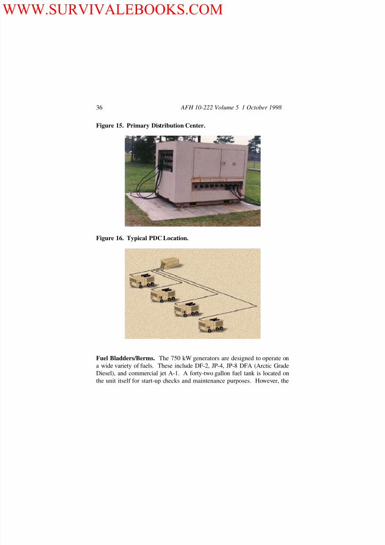
Primary Distribution Centers (PDC). The PDC (figure 15) receives and
distributes 4,160 volt, 3-phase 3-wire delta electrical power from up to four
generators. Six outputs, three on each side of the PDC, distribute high
voltage power to other components of the bare base electrical distribution
system. The use of load break elbows with the PDC allows a feeder or
generator to be easily disconnected when maintenance is needed. There are
no measuring devices on the PDC to assist the operator in determiningoverload, phase balance, power factor or underload conditions for the
individual feeders. Each PDC weights 6,660 pounds. These other
components include other PDCs or secondary distribution centers (SDCs).
Two PDCs are included in the Harvest Falcon Housekeeping Set. One PDC
is included as part of the power production facility unit type code (UTC)
XFBEX; a second PDC arrives as a separate entity under UTC XFBEF. To
ease communication and coordination between power plant operators and
minimize cable runs inside the plant, PDCs are normally positioned no
more than 80 feet from the generators. Figure 16 illustrates the typical PDC
location in relation to the primary generators. PDCs must be placed on
level ground, no more than 1% gradient. Ten feet of clearance around the
PDC and 6 feet of clearance above the PDC must be maintained. This
provides working room and allows heat dissipation.
WWW.SURVIVALEBOOKS.COM
8/13/2019 1998 Us Air Force Guide to Bare Base Power Plant Installation 67p
http://slidepdf.com/reader/full/1998-us-air-force-guide-to-bare-base-power-plant-installation-67p 38/67
AFH 10-222 Volume 5 1 October 1998 36
Figure 15. Primary Distribution Center.
Figure 16. Typical PDC Location.
Fuel Bladders/Berms. The 750 kW generators are designed to operate on
a wide variety of fuels. These include DF-2, JP-4, JP-8 DFA (Arctic Grade
Diesel), and commercial jet A-1. A forty-two gallon fuel tank is located on
the unit itself for start-up checks and maintenance purposes. However, the
WWW.SURVIVALEBOOKS.COM

8/13/2019 1998 Us Air Force Guide to Bare Base Power Plant Installation 67p
http://slidepdf.com/reader/full/1998-us-air-force-guide-to-bare-base-power-plant-installation-67p 39/67
AFH 10-222 Volume 5 1 October1998 37
750 kW generator consumes fuel at a rate of approximately 55 gallons per
hour at full load. This equates to the consumption of about 440 gallons
during an eight-hour period of operation. To ensure an adequate
continuous fuel supply, connections are provided to accept fuel from
external fuel sources, such as fuel trailers or fuel bladders. In the Harvest
Falcon system, generator fuel storage is handled by 10,000-gallon fuel
bladders (figure 17). The Housekeeping Set includes two bladders in the
power production facility UTC XFBEX. An additional bladder is part of
the Industrial Set under UTC XFBF1. Each bladder weights 230 pounds.
When setting up a power plant, normally one bladder is provided for everytwo 750 kW generators. Figure 18 depicts the common placement of the
fuel bladder with respect to the generators. The 10,000-gallon fuel bladders
have a footprint of approximately 12 feet by 42 feet when empty and a
height when filled of about 4 feet. The ground under the fuel bladders
requires some preparation, however, before bladders can be positioned. An
area 16 feet by 46 feet must be well leveled and any debris or sharp objects
must be removed. Leveling is important to prevent the bladder from
“creeping”. To prevent a massive fuel spillage in case of a tank rupture, a 3
½ foot high berm must be built around each bladder. The inside ground
dimensions of the berm should be 16 feet by 46 feet to allow a two foot
working area around the entire bladder. If sufficient material is available, a
4-inch thick sand bed should be provided under the bladder. A drain with
valve should also be installed in the berm wall to allow draining of surface
water. See figure 19 for berm details. Carefully consider where you place
the fuel bladders. Don’t put them in a location that would permit fuel from
a ruptured bladder and berm to flow downhill into other base areas or
waterways. Lastly, be sure you have developed a plan for fuel containment
in case a bladder and berm rupture or refueling operations result in major
spillage.
WWW.SURVIVALEBOOKS.COM

8/13/2019 1998 Us Air Force Guide to Bare Base Power Plant Installation 67p
http://slidepdf.com/reader/full/1998-us-air-force-guide-to-bare-base-power-plant-installation-67p 40/67
AFH 10-222 Volume 5 1 October 1998 38
Figure 17. Fuel Bladder Supporting 750-kW Generator.
Figure 18. Fuel Bladder Placement.
WWW.SURVIVALEBOOKS.COM
8/13/2019 1998 Us Air Force Guide to Bare Base Power Plant Installation 67p
http://slidepdf.com/reader/full/1998-us-air-force-guide-to-bare-base-power-plant-installation-67p 41/67

8/13/2019 1998 Us Air Force Guide to Bare Base Power Plant Installation 67p
http://slidepdf.com/reader/full/1998-us-air-force-guide-to-bare-base-power-plant-installation-67p 42/67
AFH 10-222 Volume 5 1 October 1998 40
Figure 20. Expandable Shelter Container.
Figure 21. Equipment Rack.
WWW.SURVIVALEBOOKS.COM

8/13/2019 1998 Us Air Force Guide to Bare Base Power Plant Installation 67p
http://slidepdf.com/reader/full/1998-us-air-force-guide-to-bare-base-power-plant-installation-67p 43/67
AFH 10-222 Volume 5 1 October1998 41
Figure 22. 750-kW Generator Control Panel.
Figure 23. Control Panel Cable.
WWW.SURVIVALEBOOKS.COM

8/13/2019 1998 Us Air Force Guide to Bare Base Power Plant Installation 67p
http://slidepdf.com/reader/full/1998-us-air-force-guide-to-bare-base-power-plant-installation-67p 44/67
AFH 10-222 Volume 5 1 October 1998 42
Remote Area Lighting Set (RALS). Another item included in UTC
XFBEX is a remote area lighting set (figure 24). This set is one of several
that will usually be deployed to a contingency location but this particular set
is meant to be dedicated to power plant support. It is used at a power plant
to provide overall general lighting for safety and security and specific
lighting for more critical or technical operations such as refueling. The
RALS includes a panel box/receptacle container, 13 light pole and fixture
assemblies, cables to connect the lights to the panel box, and cables to
connect the panel box to an SDC. The panel box/receptacle container also
serves as the storage and shipping container for the cables and lights.
Although the lights work using photocells, the panel box/receptacle
container should be placed within the power plant compound (perimeter
fence) for security purposes and in case manual operation is ever desired.
The cable provided for connection to an SDC is only 250 feet long,
therefore you’ll have to ensure an SDC is nearby. The same SDC should
also provide service to the power plant ESC and air conditioner. Twelve of
the 13 lights are connected to four 375-foot cable sections. Normally two
strings of six lights are set up, each string 750 feet long. Each string is
plugged into the panel box/receptacle container. The thirteenth light fixture
Figure 24. Remote Area Lighting Set.
WWW.SURVIVALEBOOKS.COM

8/13/2019 1998 Us Air Force Guide to Bare Base Power Plant Installation 67p
http://slidepdf.com/reader/full/1998-us-air-force-guide-to-bare-base-power-plant-installation-67p 45/67
AFH 10-222 Volume 5 1 October1998 43
is mounted on the panel box itself. Remember, however, that the RALS
does not have an internal power source; it relies on getting power from an
SDC. For emergency purposes, it is wise to have one or two of the TF-1
floodlight sets provided in the Harvest Falcon package immediately
available to support power plant operations.
WWW.SURVIVALEBOOKS.COM

8/13/2019 1998 Us Air Force Guide to Bare Base Power Plant Installation 67p
http://slidepdf.com/reader/full/1998-us-air-force-guide-to-bare-base-power-plant-installation-67p 46/67
AFH 10-222 Volume 5 1 October 1998 44
CONNECTIONS
Grounding of Equipment
Proper grounding of the Harvest Falcon electrical system is crucial for the
safety of our electrical and power production personnel. Procedures for
grounding of this deployable system differ little from those used in standard
electrical system installations. The grounding system for the Harvest
Falcon electrical system basically consists of ground rods at majorcomponents and grounded neutral wire throughout the high voltage
distribution portion of the system. See the applicable equipment technical
orders for specific grounding methods.
Ground rods are normally driven vertically into the earth near equipment
items to be grounded and connected to the chassis or frame of the
component with #2 AWG or #4 AWG copper wire (figure 25). Drive the
rod to a depth of at least eight feet. Soil characteristics play a large part in
the suitability of the grounding network. Ideally, a soil resistivity of 25
ohms or less is required for satisfactory grounding results. The type of soil,
its chemical contents, and the moisture level surrounding the ground rod
will determine the resistance. For example, clay and loam soils with no
rocks or stones will have a much lower resistance than clay or loam soilswith many rocks or stones. Sand and stones alone will have a much higher
resistance. Moisture content also affects resistance readings dramatically.
As moisture content increases, soil resistivity decreases. This is especially
true at the lower moisture content levels. For good grounding you basically
want the ground rod to reach a depth where the surrounding soil is always
moist. Not all locations, however, will have soil conditions favorable for
ground rod installation. You may encounter areas where a ground rod
cannot be driven deep enough. In such cases you may have to use a
horizontal ground rod installation (figure 26) or a laced wire grounding
installation (figure 27). Dig the trench as deep as feasible but be sure you
go below the frost line if you’re in a climatic zone where freezing is
possible. If soil freezes around a ground rod, the resistivity readings will
increase substantially and the suitability of the ground could be lost.
WWW.SURVIVALEBOOKS.COM

8/13/2019 1998 Us Air Force Guide to Bare Base Power Plant Installation 67p
http://slidepdf.com/reader/full/1998-us-air-force-guide-to-bare-base-power-plant-installation-67p 47/67
AFH 10-222 Volume 5 1 October1998 45
Because you aren’t as deep in the earth, you may have to place more than
one rod assembly in the trench to obtain decent resistance readings. If
ground rods are in short supply, you can use copper wire as a substitute.
The copper wire is laced up and down the bottom of the trench. When
backfilling the trench, compact as much as possible to maximize soil
contact with the wire or rods. To keep resistance readings low under
extremely adverse soil conditions, you may have to continuously keep the
grounding area damp using water or salt water solutions. Lastly, the
Harvest Falcon electrical system does not include any ground testing
equipment; bring a testing instrument with you.
Figure 25. Typical Vertical Ground Rod Installation.
WWW.SURVIVALEBOOKS.COM
8/13/2019 1998 Us Air Force Guide to Bare Base Power Plant Installation 67p
http://slidepdf.com/reader/full/1998-us-air-force-guide-to-bare-base-power-plant-installation-67p 48/67
AFH 10-222 Volume 5 1 October 1998 46
Figure 26. Horizontal Ground Rod Installation.
Figure 27. Laced Wire Grounding Installation.
Generator Grounding. Each 750 kW generator is attached to a ground rod
usually placed near the ground stud (figure 28) at the front end of the
generator. Connection is commonly made using a #4 AWG copper wire.
Grounding of the neutral wire will be discussed in a later paragraph. Do
not bond the ground rods of the generators together.
WWW.SURVIVALEBOOKS.COM

8/13/2019 1998 Us Air Force Guide to Bare Base Power Plant Installation 67p
http://slidepdf.com/reader/full/1998-us-air-force-guide-to-bare-base-power-plant-installation-67p 49/67
AFH 10-222 Volume 5 1 October1998 47
Figure 28. 750 kW Generator Ground Stud.
PDC Grounding. Ground rod installation is also required for PDC set up.
Two ground rods are driven, one on each load side of the unit. They are
connected to chassis grounding lugs located on the left front and right rear
corners of the PDC using either #2 or #4 AWG copper wire. Drive the rods
close to the grounding lugs to reduce tripping hazards (figure 29). Bond the
two ground rods together with additional copper wire.
Figure 29. PDC Ground Rod Installation.
WWW.SURVIVALEBOOKS.COM

8/13/2019 1998 Us Air Force Guide to Bare Base Power Plant Installation 67p
http://slidepdf.com/reader/full/1998-us-air-force-guide-to-bare-base-power-plant-installation-67p 50/67
AFH 10-222 Volume 5 1 October 1998 48
SDC Grounding. The grounding system for an SDC requires a single
ground rod be placed on the high voltage side of the unit. After attaching
the grounding cable (#2 or #4 AWG copper) to the rod, feed it through the
opening at the bottom of the high voltage compartment and attach it to the
ground bus located at the bottom of the primary mounting panel (figure 30).
Figure 30. Grounding Connection For An SDC.
Connections From Generators To PDCsConductors from 750kW generators to PDCs are fabricated on-site since not
all power plants will look identical or have the same “floor plan.” Included
in the Harvest Falcon housekeeping set are six cable skids (figure 31) (two
under UTC XFBEX and four under UTC XFBEG). Primary cable (#1/0
aluminum, 5-kV, cross linked polyethylene) is shipped on these skids, about
9000 feet per skid. You will have to cut this cable to length and install the
load break elbows (figure 32) which fit the 750 kW generators, PDCs and
SDCs. Follow the directions for installing the elbows carefully and be sure
that 3-4 feet of the concentric ground wire extends below each one. You
WWW.SURVIVALEBOOKS.COM

8/13/2019 1998 Us Air Force Guide to Bare Base Power Plant Installation 67p
http://slidepdf.com/reader/full/1998-us-air-force-guide-to-bare-base-power-plant-installation-67p 51/67
AFH 10-222 Volume 5 1 October1998 49
will need one cable for each of the three phases from a generator to a PDC.
Be sure to use the standard color coding for each phase so connections are
made properly. Color coding is as follows: phase A—black, phase B—red,
and phase C—blue. You can use colored tape or spray paint to mark the
cables (figure 33). If you are connecting more than one generator to a PDC,
you must ensure all cables are connected correctly by phase otherwise a
direct short will occur with accompanying equipment damage.
Figure 31. Cable Skids.
Start connecting the primary cables to the generator by first attaching each
cable’s concentric ground wire to the grounding point on the chassis of the
generator (figure 34). Physical connection of the primary cables to the
generator’s bushing well inserts must be made using the Grip-All
clamp stick. After removing the red dust caps from the bushings, position
a load break elbow over one of the bushing well inserts and push it into
place being sure that the elbow is completely seated (figure 35). This
process will need to be repeated for all three phases. Before installing load
break elbows, it is worthwhile to coat the connection points with silicone
grease. This often makes it easier to install the elbows and helps prevent
moisture and dirt from entering the connection. Repeat this process for
each generator that is to be connected to the PDC.
WWW.SURVIVALEBOOKS.COM

8/13/2019 1998 Us Air Force Guide to Bare Base Power Plant Installation 67p
http://slidepdf.com/reader/full/1998-us-air-force-guide-to-bare-base-power-plant-installation-67p 52/67
AFH 10-222 Volume 5 1 October 1998 50
Figure 32. Load Break Elbow.
Figure 33. Black, Red and Blue Markings Of Primary Cables.
WWW.SURVIVALEBOOKS.COM
8/13/2019 1998 Us Air Force Guide to Bare Base Power Plant Installation 67p
http://slidepdf.com/reader/full/1998-us-air-force-guide-to-bare-base-power-plant-installation-67p 53/67
AFH 10-222 Volume 5 1 October1998 51
Figure 34. Connection Of Concentric Ground Wires To Chassis
Grounding Point.
Figure 35. Placing Primary Cable On Generator.
After the primary cables have been connected to the generators, install the
other end of the cables onto the line side of the PDC (figure 36). When
doing so, it’s important to make sure each phase being connected to the
PDC is marked “A”, “B”, and “C” and all correspond exactly to the phase
sources from the generators. If this is not done, it will be impossible to tie
more than one generator to the PDC. Before physically connecting the
cables to the PDC bushing well inserts, connect all the concentric ground
WWW.SURVIVALEBOOKS.COM

8/13/2019 1998 Us Air Force Guide to Bare Base Power Plant Installation 67p
http://slidepdf.com/reader/full/1998-us-air-force-guide-to-bare-base-power-plant-installation-67p 54/67
AFH 10-222 Volume 5 1 October 1998 52
wires from each cable to the grounding lugs across from each connection
point (figure 37). Then connect the cables to the bushings using the Grip-
All clamp stick. Install high voltage terminal caps on all the line side
bushing well inserts that are not being used for generator connections. Any
bushing well insert not being used on the line side is energized because they
are connected to a common bus bar. When making high voltage cable
connections, work with the equipment in the unenergized state.
Figure 36. Primary Cable PDC Line Side Connection.
WWW.SURVIVALEBOOKS.COM

8/13/2019 1998 Us Air Force Guide to Bare Base Power Plant Installation 67p
http://slidepdf.com/reader/full/1998-us-air-force-guide-to-bare-base-power-plant-installation-67p 55/67
AFH 10-222 Volume 5 1 October1998 53
Figure 37. Connection Of Concentric Ground Wires On Line Side Of
PDC.
Connections From PDCs To SDCs.
High voltage connections from PDCs to SDCs are similar to those from the
generators to the PDCs. Cabling is cut to length, load break elbows are
installed on both ends of each cable, and cables are marked according to
phase. Grip-All clamp sticks are used to make all connections. The PDC
has six output feeders, three on each side of the unit. Each feeder has three
phases marked “A”, “B”, and “C.” The concentric grounds from each cable
are connected to grounding lugs below the bushing well inserts of the output
feeders (figure 38). Then the load break elbows of each cable are connected
to the bushing well inserts making sure phase coding is followed (figure
39). If any feeder circuits of the PDC are not going to be used, the arc
strangler switches (figure 40) protecting these circuits should be removed
thus totally isolating them from the power source. Additionally, red dust
WWW.SURVIVALEBOOKS.COM

8/13/2019 1998 Us Air Force Guide to Bare Base Power Plant Installation 67p
http://slidepdf.com/reader/full/1998-us-air-force-guide-to-bare-base-power-plant-installation-67p 56/67
AFH 10-222 Volume 5 1 October 1998 54
caps should be placed on all of the unused bushing well inserts to protect
them from dust, dirt, and adverse weather. Again, work with the equipment
in an unenergized state.
Figure 38. Connection Of Concentric Grounds On Load Side Of PDC.
Figure 39. PDC Load Side Feeder Connections.
WWW.SURVIVALEBOOKS.COM

8/13/2019 1998 Us Air Force Guide to Bare Base Power Plant Installation 67p
http://slidepdf.com/reader/full/1998-us-air-force-guide-to-bare-base-power-plant-installation-67p 57/67
AFH 10-222 Volume 5 1 October1998 55
Figure 40. PDC with Arc Strangler Switches Removed From Unused
Feeders.
Cables from high voltage sources are connected to the bushing well inserts
on the high voltage side of the SDCs. A single SDC can accept a three-wire
high voltage input either from a generator, PDC or another SDC. When
facing the high voltage end of the SDC, the commonly used input
connection bushings are on the left side of the panel face (figure 41).
Normally the bushings are marked as input connections and have their
proper phase identified on adjacent nameplates. Before connecting the
cables to the SDC, remove the center pole of each of the three electric
fusible disconnect switches by sliding it out of the switch using a hot stick
(figure 42). This isolates the SDC transformers from the incoming power
source. The concentric ground wires from each of the high voltage input
cables must be connected to the ground bus plates at the bottom of the panel
face (figure 43). Once the ground connections are made, the primary
cables can be placed on the input bushing well connectors (be sure correct
phase order is maintained). Any bushing well connectors on the SDC that
are not going to be used should be covered with protective insulated caps.
Once connections are made on the load side of the SDC and post-
installation checks are completed, the electric fusible disconnect center
WWW.SURVIVALEBOOKS.COM

8/13/2019 1998 Us Air Force Guide to Bare Base Power Plant Installation 67p
http://slidepdf.com/reader/full/1998-us-air-force-guide-to-bare-base-power-plant-installation-67p 58/67
AFH 10-222 Volume 5 1 October 1998 56
poles can be reinstalled (see specific equipment and distribution system
technical orders for details).
Figure 41. High Voltage Input Cables Connected to SDC Bushings.
Figure 42. Removal Of Electric Fusible Disconnect Switch Center Pole.
WWW.SURVIVALEBOOKS.COM

8/13/2019 1998 Us Air Force Guide to Bare Base Power Plant Installation 67p
http://slidepdf.com/reader/full/1998-us-air-force-guide-to-bare-base-power-plant-installation-67p 59/67
AFH 10-222 Volume 5 1 October1998 57
Figure 43. Concentric Ground Wire Connection At SDC.
Several SDCs can be connected to one feeder circuit coming from a
generator or PDC. The other two sets of bushing well inserts on the line
side panel face of an SDC are commonly used as output terminals. Cables
can be connected from these bushings and run to input bushings of other
SDCs (figure 44). Make sure proper phase order is maintained and
concentric ground wires are connected at both ends of any SDC-to-SDC
cabling.
WWW.SURVIVALEBOOKS.COM

8/13/2019 1998 Us Air Force Guide to Bare Base Power Plant Installation 67p
http://slidepdf.com/reader/full/1998-us-air-force-guide-to-bare-base-power-plant-installation-67p 60/67
AFH 10-222 Volume 5 1 October 1998 58
Figure 44. Input and Output Cables On An SDC.
Connections From Generators To Control Panels
Generator control panels are an integral component of each generator unit.
For long term operation or plant operation where several generators are in
use simultaneously, control panels are removed from the units and installed
in the control rack inside an ESC or similar facility (see figure 22). Six
control cables, each 50 feet long (see figure 23), are used to connect the
control panel to the generator. Because two cable runs are needed between
the panel and the generator, the panel location is limited to 150 feet from
the generator. Cable-to-cable connections are basic cannon plugs. One end
of each of the cable lines is attached to the wiring harnesses that the control
panel was originally connected to in the generator (figure 45); the other end
of each cable is attached to the top of the control panel in the equipment
rack.
WWW.SURVIVALEBOOKS.COM

8/13/2019 1998 Us Air Force Guide to Bare Base Power Plant Installation 67p
http://slidepdf.com/reader/full/1998-us-air-force-guide-to-bare-base-power-plant-installation-67p 61/67

8/13/2019 1998 Us Air Force Guide to Bare Base Power Plant Installation 67p
http://slidepdf.com/reader/full/1998-us-air-force-guide-to-bare-base-power-plant-installation-67p 62/67
AFH 10-222 Volume 5 1 October 1998 60
Figure 46. Fuel Storage Bladder.
Figure 47. Fuel System Manifold.
WWW.SURVIVALEBOOKS.COM

8/13/2019 1998 Us Air Force Guide to Bare Base Power Plant Installation 67p
http://slidepdf.com/reader/full/1998-us-air-force-guide-to-bare-base-power-plant-installation-67p 63/67
AFH 10-222 Volume 5 1 October1998 61
Figure 48. Fuel Hose Connected To 750-kW Generator.
Connections Between Plants
At high threat beddown locations, facility dispersal is the norm. This also
applies to power plants. Two or more plants should be established (quantity
is predicated on population and size of the installation) to ensure some
degree of electrical generation capability is retained after an attack or
similar hostile act. These plants should be part of a loop electricaldistribution network. Connections between plants can be accomplished by
interconnecting the PDCs at each plant. The #1/0 aluminum, 5-KV
primary cable and associated load break elbow connectors are used. This
cable is of the optimum size for the load requirements and provides both
adequate insulation and mechanical integrity when buried to the proper
depth. The external neutral provides additional grounding capability and
generally ensures that if personnel hit the cable with digging devices, a
short circuit will occur at the point of contact, blowing a fuse at the PDC
and hopefully avoiding injury to personnel. This cable weighs 4,603
pounds for three reels on a skid which equates to about ½ pound per linear
foot of cable. Physical connection can be made from the output bushings of
one PDC to the output bushings of another. Definitely be sure, however,
WWW.SURVIVALEBOOKS.COM

8/13/2019 1998 Us Air Force Guide to Bare Base Power Plant Installation 67p
http://slidepdf.com/reader/full/1998-us-air-force-guide-to-bare-base-power-plant-installation-67p 64/67
AFH 10-222 Volume 5 1 October 1998 62
that correct phasing is maintained and concentric grounds are properly
connected. Plants can also be interconnected through SDCs on feeder
circuits (figure 49). In figure 49, plant A feeds SDCs 1, 2, and 3 and plant
B feeds SDCs 4, 5, and 6. The cables running from SDC 1 to SDC 4 are
connected to a set of output bushings on SDC 1 and placed on parking
stands next to a set of output bushings on SDC 4. If plant A is put out of
service for some reason, it is isolated from the system and the cables at SDC
4 are removed from the parking stands and placed on the output bushings to
energize SDCs 1, 2, and 3. Alternatively, the links between SDCs 1 and 4
and 3 and 6 can be made as the system is initially installed. In any case,again ensure correct phasing is maintained and concentric grounds are
connected properly.
Figure 49. Power Plants Interconnected Through SDCs.
WWW.SURVIVALEBOOKS.COM
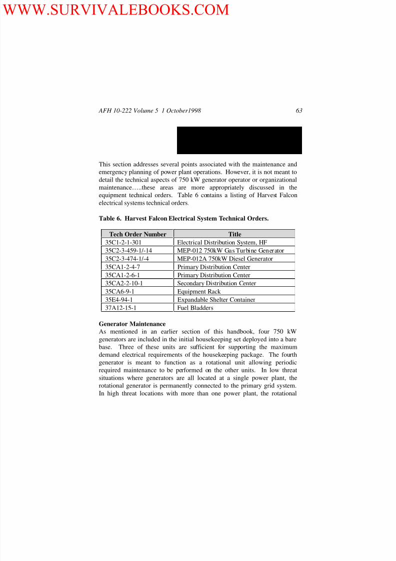
8/13/2019 1998 Us Air Force Guide to Bare Base Power Plant Installation 67p
http://slidepdf.com/reader/full/1998-us-air-force-guide-to-bare-base-power-plant-installation-67p 65/67
8/13/2019 1998 Us Air Force Guide to Bare Base Power Plant Installation 67p
http://slidepdf.com/reader/full/1998-us-air-force-guide-to-bare-base-power-plant-installation-67p 66/67
AFH 10-222 Volume 5 1 October 1998 64
generator is moved to the proper location when one generator is taken out of
service. When more than one power plant is required, generators are
interconnected in a loop system so that failure of a generator at one location
does not interrupt service.
Maintaining data logs is often regarded as a nuisance factor in the day-to-
day operational atmosphere. Nevertheless, these logs serve an important
purpose. They assist you in keeping track of required maintenance needs,
furnish trend information on operating characteristics, and often provide
key data for analysis of power production problems.
PDC Maintenance
Since a PDC is basically a static device, maintenance is relatively minimal,
a worthy attribute in a deployed situation. Several visual inspection tasks
should be periodically performed however, and some preventive
maintenance is required. See TO 35CA1-2-6-1 for details. Major items
that require inspection and maintenance attention include:
Fused switch assemblies
Grounds and concentric conductors
Case and doors
Bushing well insert assemblies
Internal components—dielectric testing
Emergency PlanningUnder routine conditions power plant operations can become very
methodical and predictable. When emergency situations arise, however,
one must be prepared for many situations and be able to respond rapidly and
correctly. This capability must be preplanned and not based on instinct.
An emergency operating plan is crucial for ensuring our people know what
to do when a crisis occurs. This plan should include procedures to be
followed under any of the following conditions:
Major trouble on the primary distribution system.
Partial outage of the electrical supply.
Prolonged outage of the electrical supply.
Major fuel/hazardous chemical spill.
WWW.SURVIVALEBOOKS.COM

8/13/2019 1998 Us Air Force Guide to Bare Base Power Plant Installation 67p
http://slidepdf.com/reader/full/1998-us-air-force-guide-to-bare-base-power-plant-installation-67p 67/67
AFH 10-222 Volume 5 1 October1998 65
The plan should also include or address the following:
A single line drawing of the total electrical distribution network. Major
feeder circuits should be identified and each power plant, PDC and SDC
location clearly marked. If cables have been buried, their locations should
also be clearly delineated.
Facility priority list (used for determining MEP generator placement
priorities in case of facility damage).
Refueling under emergency conditions. Procedures for refueling both
low voltage MEP generators and 750 kW units should be spelled out toinclude responsibilities, timing, types and quantities of fuel, etc.)
Movement of low voltage MEP generators under emergency conditions.
This includes vehicle requirements, tools, cabling requirements, etc.
Location and availability of spare parts and consumable items.
Contact points and procedures for ordering government-furnished
supplies and equipment.
Local sources of resupply, fuel, and generating equipment.
Procedures for emergency load shedding identifying what circuits to
isolate and in what priority.
WILLIAM P. HALLIN, Lt General, USAF
DCS/Installations & Logistics
WWW.SURVIVALEBOOKS.COM


