ANDREAS MAIER FELLBACH ∙ www.amf.de 3 1A 4 2 1B LOCKING CONTROL AUTOMATION SOLUTIONS FROM AMF The enormous capability and flexibility of use of modern processing machines is undisputed. To be able to use these capabilities in reality requires more than just fast machines. An automation solution consists today of a number of multiply linked, versatile products and technologies. Through the possibility of a fully automatic and process-sure machine configuration, our automation solutions meet the requirements for seamless integration into the automation system. Numerous sensing options, optional media ducts and blow-out and blow-off of the modules speak for themselves! Persuade yourself of the automation potential of the AMF zero-point clamping modules! _1A IS THE MODULE LOCKED? Through the direct monitoring of the piston position (opened) by means of pneumatic back pressure, the position can be sensed by means of a differential pressure switch. _1B IS THE MODULE LOCKED? With an open module, the integrated stop valve creates a pneumatic or hydraulic static pressure, which is sensed via a differential pressure switch. LOCKING CONTROL SUPPORT CONTROL BLOW OUT CENTRAL LOCK 1A LOCKING CONTROL
Transcript
ANDREAS MAIER FELLBACH ∙ www.amf.de Zero-Point-SyStemS 67
3
1A
4
2
1b lOCKing COntrOl
autOmatiOn sOlutiOns frOm amf
The enormous capability and flexibil ity of use of modern processing
machines is undisputed. To be able to use these capabilities in reality
requires more than just fast machines. An automation solution consists
today of a number of multiply l inked, versatile products and technologies.
Through the possibility of a fully automatic and process-sure machine
configuration, our automation solutions meet the requirements for
seamless integration into the automation system. Numerous sensing
options, optional media ducts and blow-out and blow-off of the modules
speak for themselves!
Persuade yourself of the automation potential of the
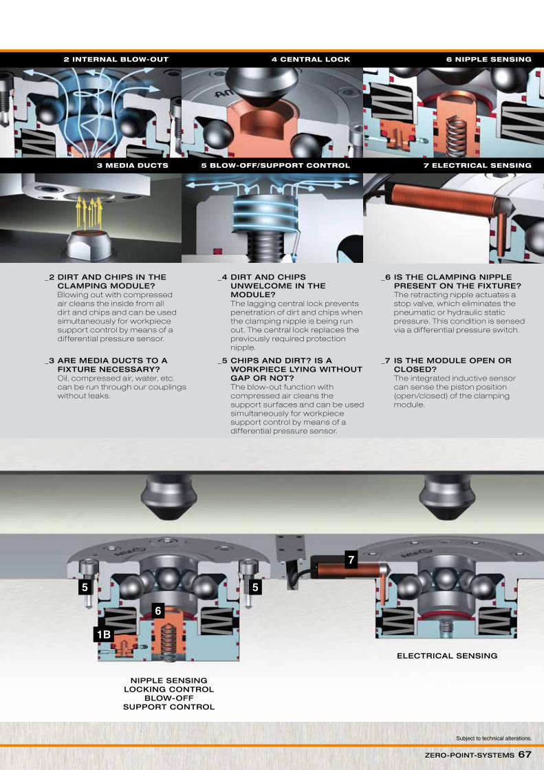
Amf zero-point clamping modules! _1A iS tHe moduLe LoCKed? Through the direct monitoring of the piston position (opened) by means of pneumatic back pressure, the position can be sensed by means of a dif ferential pressure switch.
_1b iS tHe moduLe LoCKed? With an open module, the integrated stop valve creates a pneumatic or hydraulic static pressure, which is sensed via a dif ferential pressure switch.
LoCKinG ControLSuPPort ControL
bLoW out CentrAL LoCK
1a lOCKing COntrOl
ANDREAS MAIER FELLBACH ∙ www.amf.de Zero-Point-SyStemS 67
Subject to technical alterations.
6
7
1B
5 5
_2 dirt And CHiPS in tHe CLAmPinG moduLe? Blowing out with compressed air cleans the inside from all dirt and chips and can be used simultaneously for workpiece support control by means of a dif ferential pressure sensor.
_5 CHiPS And dirt? iS A WorKPieCe LyinG WitHout GAP or not?
The blow-out function with compressed air cleans the support surfaces and can be used simultaneously for workpiece support control by means of a dif ferential pressure sensor.
_3 Are mediA duCtS to A fiXture neCeSSAry?
Oil, compressed air, water, etc. can be run through our couplings without leaks.
_4 dirt And CHiPS unWeLCome in tHe moduLe? The lagging central lock prevents penetration of dirt and chips when the clamping nipple is being run out. The central lock replaces the previously required protection nipple.
_7 iS tHe moduLe oPen or CLoSed? The integrated inductive sensor can sense the piston position (open/closed) of the clamping module.
_6 iS tHe CLAmPinG niPPLe PreSent on tHe fiXture? The retracting nipple actuates a stop valve, which eliminates the pneumatic or hydraulic static pressure. This condition is sensed via a dif ferential pressure switch.
3 media duCts 5 blOW-Off/suppOrt COntrOl 7 eleCtriCal sensing
niPPLe SenSinGLoCKinG ControL
bLoW-offSuPPort ControL
eLeCtriCAL SenSinG
1a lOCKing COntrOl 2 internal blOW-Out 4 Central lOCK 6 nipple sensing
ANDREAS MAIER FELLBACH ∙ www.amf.de Zero-Point-SyStemS 69
5 - 6 5 - 6Operating pressure for pneum. re-clamping. min. - max. [bar]
50 - 60 60 - 70 25 - 50Operating pressure for hydr. opening min. - max. [bar]
20Operating pressure for hydr. re-clamping. min. - max. [bar]
● ● ● ● ● Pneum. blow-out
● ● ● ● ● ● Pneum. support control
● ● ● ● ● Pneum. locking control
● ● Hydr. locking control
● ● ● Pneum. clamping nipple sensing
● Hydr. clamping nipple sensing
● ● ● Sensor monitor opened
● ● ● Sensor monitor closed
Sensor monitor clamping nipple
● Central lock with pneum. turbine blow-out
● ● Central lock with pneum. blow-out
Subject to technical alterations.
70 Zero-Point-SyStemS ANDREAS MAIER FELLBACH ∙ www.amf.de
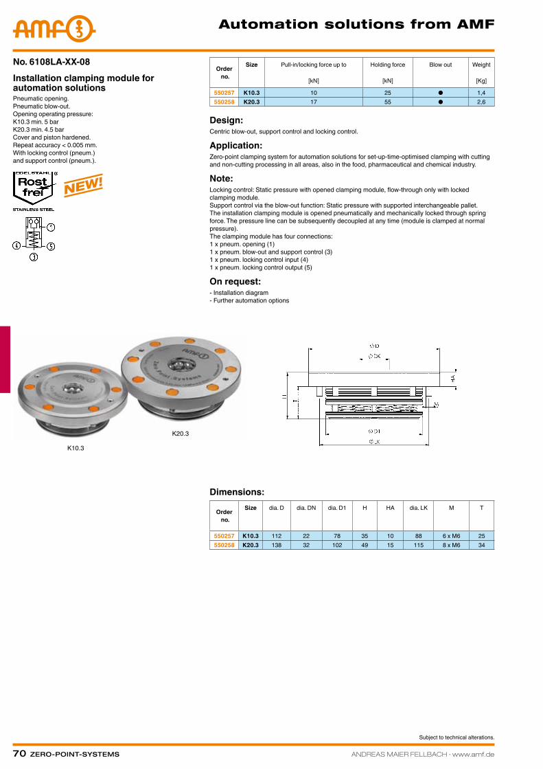
Pneumatic opening. Pneumatic blow-out. Opening operating pressure: K10.3 min. 5 bar K20.3 min. 4.5 bar Cover and piston hardened. Repeat accuracy < 0.005 mm. With locking control (pneum.) and support control (pneum.).
Installation clamping module for automation solutions
No. 6108LA-XX-08Order no.
Size Pull-in/locking force up to
[kN]
Holding force
[kN]
Blow out Weight
[Kg]
550257 K10.3 10 25 ● 1,4550258 K20.3 17 55 ● 2,6
Design:Centric blow-out, support control and locking control.
Application:Zero-point clamping system for automation solutions for set-up-time-optimised clamping with cutting and non-cutting processing in all areas, also in the food, pharmaceutical and chemical industry.
Note:Locking control: Static pressure with opened clamping module, flow-through only with locked clamping module. Support control via the blow-out function: Static pressure with supported interchangeable pallet. The installation clamping module is opened pneumatically and mechanically locked through spring force. The pressure line can be subsequently decoupled at any time (module is clamped at normal pressure). The clamping module has four connections: 1 x pneum. opening (1) 1 x pneum. blow-out and support control (3) 1 x pneum. locking control input (4) 1 x pneum. locking control output (5)
On request:- Installation diagram - Further automation options
ANDREAS MAIER FELLBACH ∙ www.amf.de Zero-Point-SyStemS 71
Pneumatic opening. Pneumatic blow-out. Opening operating pressure: K10.3 min. 5 bar K20.3 min. 4.5 bar Cover and piston hardened. Repeat accuracy < 0.005 mm. With locking control (pneum.) and support control (pneum.) and clamping nipple sensing (pneum.).
Installation clamping module for automation solutions
No. 6108LA-XX-08Order
no.
Size Pull-in/locking force up to
[kN]
Holding force
[kN]
Blow out Weight
[Kg]
550259 K10.3 10 25 ● 1,4550260 K20.3 17 55 ● 2,6
Design:Centric blow-out, support control, locking control and clamping nipple sensing.
Application:Zero-point clamping system for automation solutions for set-up-time-optimised clamping with cutting and non-cutting processing in all areas, also in the food, pharmaceutical and chemical industry.
Note:Locking control: Static pressure with opened clamping module, flow-through only with locked clamping module. Clamping nipple sensing: Static pressure with clamping nipple present, flow-through if clamping nipple is not present. Support control via the blow-out function: Static pressure with supported interchangeable pallet. The installation clamping module is opened pneumatically and mechanically locked through spring force. The pressure line can be subsequently decoupled at any time (module is clamped at normal pressure). The clamping module has five connections: 1 x pneum. opening (1) 1 x pneum. blow-out and support control (3) 1 x pneum. locking control inlet (4) 1 x pneum. locking control output (5) 1 x pneum. clamping nipple sensing input (6) 1 x pneum. clamping nipple sensing output (5)
On request:- Installation diagram - Further automation options
72 Zero-Point-SyStemS ANDREAS MAIER FELLBACH ∙ www.amf.de
automation solutions from amf
Pneumatic opening. Pneumatic blow-out. Opening operating pressure: K10.3 min. 5 bar K20.3 min. 4.5 bar Cover and piston hardened. Repeat accuracy < 0.005 mm. With locking control (pneum.) and support control (pneum.) and clamping nipple sensing (pneum.) and isolated solution.
Installation clamping module for automation solutions
No. 6108LA-XX-10Order no.
Size Pull-in/locking force up to
[kN]
Holding force
[kN]
Blow out Weight
[Kg]
550261 K10.3 10 25 ● 1,4550262 K20.3 17 55 ● 2,6
Design:Support surfaces as isolated design with integrated blow-out, centric blow-out, support control, locking control and clamping nipple sensing.
Application:Zero-point clamping system for automation solutions for set-up-time-optimised clamping with cutting and non-cutting processing in all areas, also in the food, pharmaceutical and chemical industry.
Note:Locking control: Static pressure with opened clamping module, flow-through only with locked clamping module. Clamping nipple sensing: Static pressure with clamping nipple present, flow-through if clamping nipple is not present. Support control: Static pressure with supported interchangeable pallet. The installation clamping module is opened pneumatically and mechanically locked through spring force. The pressure line can be subsequently decoupled at any time (module is clamped at normal pressure). The clamping module has 6 connections: 1 x pneum. opening (1) 1 x pneum. blow-out (3) 1 x pneum. locking control inlet (4) 1 x pneum. locking control output (5) 1 x pneum. clamping nipple sensing input (6) 1 x pneum. clamping nipple sensing output (5) 1 x pneum. Support control (7)
On request:- Installation diagram - Further automation options
ANDREAS MAIER FELLBACH ∙ www.amf.de Zero-Point-SyStemS 73
Hydraulic opening. Pneumatic blow-out. Opening operating pressure: min. 60 bar - max. 70 bar Cover and piston hardened. Repeatability < 0.005 mm. With locking control (pneumatic) and support control (pneumatic).
Installation clamping module for automation solutions
No. 6103HA-20-05Order
no.
Size Pull-in/locking force up to
[kN]
Holding force
[kN]
Blow out Weight
[Kg]
428409 K20 20 55 ● 1,4
Design:Centrical blow-out, support control and locking control.
Application:Zero-point clamping system for automation solutions for set-up-time-optimized clamping with cutting and non-cutting processing in all areas, also in the food, pharmaceutical and chemical industry.
Note:Locking control: Static pressure with opened clamping module, flow-through only with locked clamping module. Support control via the blow-out function: Static pressure with supported change pallet. The installation clamping module is opened hydraulically (1) and mechanically locked through spring force. Subsequent uncoupling of the pressure lines is possible at all times (module is tensioned pressure-free). The clamping module has four connections: 1x hydr. opening (1) / 1x pneum. blow-out and support control (3) / 1x pneum. locking control input (4) / 1x pneum. locking control output (5).
On request:- Installation diagrams - Additional automation options
Dimensions:
Order no.
Size dia. D dia. DN dia. D1 H HA M dia. LK T
428409 K20 112 32 78 44 10 M6 88 34
Hydraulic opening. Opening operating pressure: min. 50 bar - max. 60 bar Cover and piston hardened. Repeatability < 0.005 mm. With locking control (hydraulic or pneumatic), support control (pneumatic) and nipple sensing.
Installation clamping module for automation solutions
No. 6100H-20-06Order
no.
Size Pull-in/locking force up to
[kN]
Holding force
[kN]
Weight
[Kg]
427161 K20 20 55 2,8
Design:Support surfaces as island design with integrated blow-out, locking control and nipple sensing.
Application:Zero-point clamping system for automation solutions for set-up-time-optimized clamping with cutting and non-cutting processing in all areas, also in the food, pharmaceutical and chemical industry.
Note:Locking control: Static pressure with opened clamping module, flow-through only with locked clamping module and presence of clamping nipple. Support control: Static pressure with supported change pallet. This is opened hydraulically (1) and mechanically locked through spring force. Subsequent uncoupling of the pressure lines is possible at all times (module is tensioned pressure-free). The clamping module has four connections: 1x hydr. opening (1) / 1x pneum. support control (3) / 1x hydr. or pneum. locking control and nipple sensing input (4) / 1x hydr. or pneum. locking control and nipple sensing output (5).
On request:- Installation diagrams - Additional automation options
Dimensions:
Order no.
Size dia. D dia. DN dia. D1 H HA dia. LK M T
427161 K20 112 32 78 57 10 88 M6 47
automation solutions from amf
CAD
CAD
Subject to technical alterations.
74 Zero-Point-SyStemS ANDREAS MAIER FELLBACH ∙ www.amf.de
Hydraulic opening. Pneumatic blow-out. Operating pressure: 60 bar - 70 bar Cover and piston hardened. Repeat accuracy < 0.005 mm. With locking control (pneum.) and support control (pneum.).
Installation clamping module with central lock for automation solutions
No. 6107HA-20-07Order no.
Size Pull-in/locking force up to
[kN]
Holding force
[kN]
Blow out Weight
[Kg]
550279 K20 20 55 ● 1,4
Design:With central lock, blow-out, support control and locking control.
Application:Zero-point clamping system for automation solutions for set-up-time-optimised clamping with cutting and non-cutting processing in all areas, also in the food, pharmaceutical and chemical industry.
Note:Central lock with pneum. cleaning function of support surfaces. Locking control: Static pressure with opened clamping module, flow-through only with locked clamping module. Support control via the blow-out function: Static pressure with supported interchangeable pallet. The installation clamping module is opened hydraulically and mechanically locked through spring force. The pressure line can be subsequently decoupled at any time (module is clamped at normal pressure). The clamping module has four connections: 1 x hydr. opening (1) 1 x pneum. blow-out and support control (3) 1 x pneum. locking control inlet (4) 1 x pneum. locking control output (5)
Dimensions:
Order no.
Size dia. D dia. DN dia. D1 H HA dia. LK M T
550279 K20 112 32 78 44 10 88 M6 34
neW!
automation solutions from amf
Subject to technical alterations.
ANDREAS MAIER FELLBACH ∙ www.amf.de Zero-Point-SyStemS 75
Automation solution (order no. 427161) with lock and support control as well as nipple sensing in use in a fully automated production process with robot loading.
„Turbine“ high-end clamping module (order no. 420919) in use in a fully automated production process with robot loading.
automation solutions from amf
Subject to technical alterations.
76 Zero-Point-SyStemS ANDREAS MAIER FELLBACH ∙ www.amf.de
Hydraulic opening. Opening operating pressure: 25-50 bar Retensioning operating pressure: 20 bar Cover and piston hardened. Repeatability < 0.005 mm.
„Turbine“ high-end clamping module for full automation
No. 6102HOrder no.
Size Pull-in/locking force up to
[kN]
Holding force
[kN]
Weight
[Kg]
420919 K23 23 23 4,8
Application:For fully automatic clamping solutions for use as machine table support in processing centres with automatic pallet changing system or robot loading and for installation in pallets, machine tables, clamping brackets and cubes. Many possible versatile uses in automation.
Note:Hardened support surfaces as island design with integrated support control. Additional blowing off of the support surfaces by centrically running-out turbine spindles and blowing out of the sphere space Additional hydraulic 6 mm lift-out of the pallet to be changed for easier pallet removal. Sensing options: - Support control (pneumatic) - Locking control (hydraulic)Turbine has six connections: 1x hydr. opening (1) / 1x hydr. retensioning (2) / 1x pneum. support control (3) / 1x blow-off, blow-out and pneum. turbine blow-off (4) / 1x hydr. locking control (5) / 1x run out short stroke piston (6).
On request:- Installation diagrams
„turbine“ high-end clamping module
Dimensions:
Order no.
Size dia. D dia. DN dia. D1 H HA dia. LK T
420919 K23 129 32 99 70 30 115 40CAD
Subject to technical alterations.
ANDREAS MAIER FELLBACH ∙ www.amf.de Zero-Point-SyStemS 77
„turbine“ high-end Clamping mOdule fOr full autOmatiOnThis high-end clamping module is used for
optimised tool clamping times in fully automatic
processing centres with pallet changing systems or
robot loading.
> Turbine blow-off of the hardened support and
housing surface
> Pneumatic support control
> Hydraulic unlocking control
> Hydraulic lif ting of the pallet (6 mm) after opening
of the clamping module
> Material: stainless steel
> Hardened support surface on the connection
fitting with defined, measurable height
Subject to technical alterations.
78 Zero-Point-SyStemS ANDREAS MAIER FELLBACH ∙ www.amf.de
Application:Zero point clamping system for automation solutions for time-optimised clamping during cutting and non-cutting machining in all sectors, as well as in the food, pharmaceutical and chemical industries.
Note:The clamping module has two inductive sensors (connection type: connector S8, cable length 150 mm) for the status check (opened / locked). This is opened pneumatically (1) and mechanically locked through spring force. The pressure line can be subsequently decoupled at any time (module is clamped depressurised). The clamping module has one connection: 1 x pneum. opening (1).
On request:- Installation diagrams - Further automation solutions.
Pneumatic opening. Opening operating pressure: min. 5 bar - max. 12 bar Cover and piston hardened. Flange housing: Aluminium Repeat accuracy < 0.005 mm.
Clamping module with sensor monitor and mounting flange
No. 6104LOrder no.
Size Pull-in/locking force up to
[kN]
Holding force
[kN]
Weight
[Kg]
526574 K10.3 10 25 2,6526590 K20.3 17 55 5,0
Dimensions:
Order no.
Size dia. DA dia. D dia. DN H HA K dia. LK dia. M dia. N H7 R
ANDREAS MAIER FELLBACH ∙ www.amf.de Zero-Point-SyStemS 79
Pneumatic opening. Opening operating pressure: min. 5 bar - max. 12 bar Cover and piston hardened. Flange housing: Aluminium Repeat accuracy < 0.005 mm.
Clamping module with sensor monitor and nipple sensing
No. 6105L
Application:Zero point clamping system for automation solutions for time-optimised clamping during cutting and non-cutting machining in all sectors, as well as in the food, pharmaceutical and chemical industries.
Note:The clamping module has two inductive sensors (connection type: connector S8, cable length 150 mm) for the status check for opened/locked and the presence of the clamping nipple. This is pneumatically opened (1) and mechanically locked by spring force. The pressure line can be subsequently decoupled at any time (module is clamped depressurised). The clamping module has one connection: 1 x pneum. opening (1).
On request:- Installation diagrams - Further automation solutions.
Order no.
Size Pull-in/locking force up to
[kN]
Holding force
[kN]
Weight
[Kg]
526616 K10.3 10 25 2,6
Dimensions:
Order no.
Size dia. DA dia. D dia. DN H HA K dia. LK dia. M dia. N H7 R
526616 K10.3 142 112 22 38 48 23 127 6,6 8 G1/8
neW!
automation solutions from amf
CAD
Subject to technical alterations.
80 Zero-Point-SyStemS ANDREAS MAIER FELLBACH ∙ www.amf.de
Pneumatic opening. Opening operating pressure: min. 8 bar - max. 12 bar Re-clamping operating pressure: min. 5 bar - max. 6 bar Cover and piston hardened. Flange housing: Aluminium Repeat accuracy < 0.005 mm.
Clamping module with sensor monitor and nipple sensing
No. 6106L
Application:Zero point clamping system for automation solutions for time-optimised clamping during cutting and non-cutting machining in all sectors, as well as in the food, pharmaceutical and chemical industries.
Note:The clamping module has two inductive sensors (connection type: connector S8, cable length 150 mm) for the status check for opened/locked and the presence of the clamping nipple. This is pneumatically opened (1) and mechanically locked by spring force. The pressure line can be subsequently decoupled at any time (module is clamped depressurised). The clamping module has two connections: 1 x pneum. opening (1) / 1 x pneum. re-clamping (turbo) (2).
On request:- Installation diagrams - Further automation solutions.
Order no.
Size Pull-in/locking force up to
[kN]
Holding force
[kN]
Weight
[Kg]
526632 K10 8 25 1,0
Dimensions:
Order no.
Size dia. DA dia. D dia. DN H HA K dia. LK dia. M dia. N H7 R
526632 K10 104 78 22 37 44 28 90 6,6 8 G1/8
neW!
automation solutions from amf
CAD
Subject to technical alterations.
ANDREAS MAIER FELLBACH ∙ www.amf.de Zero-Point-SyStemS 81
Pneumatic opening. Opening operating pressure: min. 8 bar - max. 12 bar Retensioning operating pressure (turbo): min. 5 bar - max. 6 bar Cover and piston hardened. Repeatability < 0.005 mm.
Clamping module with sensor monitor and mounting flange
Application:Zero-point clamping system for automation solutions for set-up-time-optimized clamping with cutting and non-cutting processing in all areas, also in the food, pharmaceutical and chemical industry.
Note:The installation clamping module with sensor monitor contains 2 inductive sensors (connection type: S8 plug, cable length: 150 mm) for condition control (open / locked). This is pneumatically opened (1) and mechanically locked through spring force. To achieve the specified pull-in and locking forces, it must be briefly retensioned pneumatically (turbo) (2). Subsequent uncoupling of the pressure lines is possible at all times (module is tensioned pressure-free).Use of the pneumatic pressure intensifier 6370ZVL is recommended.Clamping module has two connections: 1x pneum. opening (1) / 1x pneum. retensioning (turbo) (2).
On request:- Installation diagrams - Additional automation options
Dimensions:
Order no.
Size dia. DA dia. D dia. DN H HA K dia. LK dia. M dia. N H7 R