166

Table 1-1:
SIMODRIVE 611, SIMOVERT MASTERDRIVES MC
1FK7 Synchronous Motors
Configuration Manual
10/2005 Edition
Table 1-10:
Foreword
Table 1-2:
Motor Description 1Table 1-3:
Electrical Connections 2Table 1-4:
Technical Data and Charac-teristics 3Table 1-5:
Motor Components (Options) 4Table 1-6:
Gearboxes 5Table 1-7:
Dimension Drawings 6Table 1-8:
Appendix ATable 1-9:
Safety information/instructionsThis manual contains information which you should carefully observe to ensure your own personal safety and to prevent material damage. The notices referring to your personal safety are highlighted in the manual by a safety alert symbol, notices referring to property damage only, have no safety alert symbol The warnings appear in decreasing order of risk as given below.
If several hazards of different degrees occur, the hazard with the highest degree must always be given priority. If a warning note with a warning triangle warns of personal injury, the same warning note can also contain a warning of material damage.
Qualified personnelThe associated device/system may only be set up and operated using this documentation. Commissioning and operation of a device/system may only be performed by qualified personnel. Qualified persons are defined as persons who are authorized to commission, to ground, and to tag circuits, equipment, and systems in accordance with established safety practices and standards.
Correct usagePlease note the following:
Registered trademarksAll designations with the trademark symbol ® are registered trademarks of Siemens AG. Other designations in this documentation may be trademarks whose use by third parties for their own purposes can violate the rights of the owner.
Disclaimer of liabilityWe have checked the contents of this manual for agreement with the hardware and software described. Since devi-ations cannot be precluded entirely, we cannot guarantee full agreement. The information given in this publication is reviewed at regular intervals and any corrections that might be necessary are made in the subsequent editions.
Danger
indicates that death or severe personal injury will result if proper precautions are not taken.
Warning
indicates that death or severe personal injury may result if proper precautions are not taken.
Caution
with a warning triangle indicates that minor personal injury can result if proper precautions are not taken.
Caution
without a warning triangle means that material damage can occur if the appropriate precautions are not taken.
Notice
indicates that an unwanted result or situation can result if the appropriate advice is not taken into account.
Warning
The device may be used only for the applications described in the catalog and in the technical description, and only in combination with the equipment, components and devices of other manufacturers where recommended or per-mitted by Siemens. Correct transport, storage, installation and assembly, as well as careful operation and mainte-nance, are required to ensure that the product operates safely and without faults.
Siemens AGAutomation and DrivesPostfach 48 48D-90437 NUREMBERGGERMANY
Document Order No. 6SN1197-0AD06-0BP110/2005 Edition
Copyright © Siemens AG 2003 - 2005.Subject to change without prior notice
1FK7 Synchronous MotorsConfiguration Manual (PFK7), 10/2005 Edition, 6SN1197-0AD06-0BP1 iii
ForewordTable -1: Information on the documentation
Information on the documentationThis document is part of the Technical Customer Documentation which has been developed for SIMODRIVE and SIMOVERT MASTERDRIVES MC (Motion Control). All of the docu-ments are available individually. The documentation list, which includes all Advertising Brochures, Catalogs, Overviews, Short Descriptions, Operating Instructions and Technical Descriptions with Order No., ordering address and price can be obtained from your local Siemens office.
This document does not purport to cover all details or variations in equipment, nor to provide for every possible contingency to be met in connection with installation, operation or mainte-nance.
We would also like to point-out that the contents of this document are neither part of nor modify any prior or existing agreement, commitment or contractual relationship. The sales contract contains the entire obligations of Siemens. The warranty contained in the contract between the parties is the sole warranty of Siemens. Any statements contained herein neither create new warranties nor modify the existing warranty.
Table -2: Structure of the documentation
Structure of the documentation for 1FK and 1FT motors
Table: Configuration Manual, individual sections
Title Order number (MLFB) LanguageSynchronous Motors, General Section for SIMODRIVE 611, SIMOVERT MASTERDRIVES MC
6SN1197–0AD07–0BP English
Synchronous Motors, 1FK7 Motor Section for SIMODRIVE 611 and MASTERDRIVES MC
6SN1197–0AD06–0BP English
Synchronous Motors, 1FK7 Motor Section for SIMODRIVE 611 and MASTERDRIVES MC
6SN1197–0AD05–0BP English
Synchronous Motors, 1FK7 Motor Section for SIMODRIVE 611 and MASTERDRIVES MC
6SN1197–0AD02–0BP English
Synchronous Motors, 1FT5 Motor Section for SIMODRIVE 611
6SN1197–0AD01–0BP English
Foreword
1FK7 Synchronous Motorsiv Configuration Manual (PFK7), 10/2005 Edition, 6SN1197-0AD06-0BP1
Target group of the Configuration ManualThe Configuration Manual addresses planners and design engineers. It supports you when selecting motors, calculating the drive components, selecting the required accesso-ries as well as when selecting line and motor-side power options.
Table -1: Technical Support_normal
Technical supportIf you have any questions, please contact the following Hotline:
Please send any questions about the documentation (e.g. suggestions for improvement, corrections) to the following fax number or email address:
Information on the productsUp-to-date information about our products can be found on the Internet at the following address:
Tel.: +49 (0) 180 5050–222
Fax: +49 (0) 180 5050–223
Internet: http://www.siemens.com/automation/support-request
Fax: +49 (0) 9131 98–63315
Fax form: Refer to the correction sheet at the end of the document
E-mail: [email protected]
http://www.siemens.com/motioncontrol
1FK7 Synchronous MotorsConfiguration Manual (PFK7), 10/2005 Edition, 6SN1197-0AD06-0BP1 v
Foreword
Table -2: Danger and warning information
Danger and warning information
DangerStart-up/commissioning is absolutely prohibited until it has been completely ensured that the machine, in which the components described here are to be installed, is in full compliance with the specifications of Directive 98/37/EC.
Only appropriately qualified personnel may commission SIMODRIVE and SIMOVERT MASTERDRIVES drive units and the motors.
This personnel must carefully observe the technical customer documentation associated with this product and be knowledgeable about and carefully observe the danger and warning infor-mation.
Operational electrical equipment and motors have parts and components which are at hazardous voltage levels.
When the machine or system is operated, hazardous axis movements can occur.
All of the work carried-out on the electrical machine or system must be carried-out with it in a no-voltage condition.
SIMODRIVE and SIMOVERT MASTERDRIVES drive units have been designed to be con-nected to line supplies grounded through a low-ohmic connection (TN line supplies). For addi-tional information please refer to the appropriate documentation for the drive converter systems.
WarningThe successful and safe operation of this equipment and motors is dependent on professional transport, storage, installation and mounting as well as careful operator control, service and maintenance.
For special versions of the drive units and motors, information and data in the catalogs and quotations additionally apply.
In addition to the danger and warning information/instructions in the technical customer docu-mentation supplied, the applicable domestic, local and plant-specific regulations and require-ments must be carefully taken into account.
CautionThe motors can have surface temperatures of over +100 °C.
This is the reason that temperature-sensitive components, e.g. cables or electronic compo-nents may neither be in contact nor be attached to the motor.
When connecting-up cables, please observe that they– are not damaged– are not subject to tensile stress– cannot be touched by rotating components.
Foreword
1FK7 Synchronous Motorsvi Configuration Manual (PFK7), 10/2005 Edition, 6SN1197-0AD06-0BP1
Table -3: ESDS information and instructions
CautionMotors should be connected-up according to the circuit diagram provided. They must not be connected directly to the three-phase supply because this will damage them.
SIMODRIVE and SIMOVERT MASTERDRIVES drive units with AC motors are subject, as part of the type test, to a voltage test corresponding to EN 50178. According to EN 60204-1, Section 19.4, while electrical equipment of industrial machines are being subject to a voltage test, all of the SIMODRIVE and SIMOVERT MASTERDRIVES drive unit connections must be disconnected/withdrawn in order to avoid damaging the SIMODRIVE and SIMOVERT MASTERDRIVES drive units.
NoteSIMODRIVE and SIMOVERT MASTERDRIVES drive units with motors fulfill, when opera-tional and in dry equipment rooms, the Low-Voltage Directive 73/23/EEC.
SIMODRIVE and SIMOVERT MASTERDRIVES drive units with motors fulfill, in the configura-tions specified in the associated EC Declaration of Conformity, EMC Directive 89/336/EEC.
1FK7 Synchronous MotorsConfiguration Manual (PFK7), 10/2005 Edition, 6SN1197-0AD06-0BP1 vii
Foreword
ESDS instructions
Standards, regulationsThe appropriate standards, regulations are directly assigned to the functional requirements.
CautionAn electrostatic-sensitive device (ESDS) is an individual component, integrated circuit, or module that can be damaged by electrostatic fields or discharges.
ESDS regulations for handling boards and equipment:
When handling components, make sure that personnel, workplaces, and packaging are well earthed.
Personnel in ESD zones with conductive floors may only touch electronic components if they are – grounded through an ESDS bracelet and– wearing ESDS shoes or ESDS shoe grounding strips.
Electronic boards should only be touched if absolutely necessary.
Electronic boards must not come into contact with plastics or items of clothing containing synthetic fibers.
Electronic boards may only be placed on conductive surfaces (table with ESDS surface, conductive ESDS foam rubber, ESDS packing bag, ESDS transport containers).
Electronic boards may not be brought close to data terminals, monitors or television sets. (minimum clearance >10 cm).
Measurements may only be carried-out on electronic boards and modules if– the measuring instrument is grounded (e.g. via a protective conductor) or– before making measurements with a potential-free measuring device, the measuring head is briefly discharged (e.g. by touching an unpainted blank piece of metal on the control cabinet).
Foreword
1FK7 Synchronous Motorsviii Configuration Manual (PFK7), 10/2005 Edition, 6SN1197-0AD06-0BP1
1FK7 Synchronous MotorsConfiguration Manual (PFK7), 10/2005 Edition, 6SN1197-0AD06-0BP1 ix
Table of Contents
Foreword ................................................................................................................................................... iii
1 Motor Description .................................................................................................................................. 1-1
1.1 Overview................................................................................................................................... 1-1
1.2 Technical data .......................................................................................................................... 1-2
1.3 Selection and ordering data...................................................................................................... 1-41.3.1 1FK7 Compact motors - core type, natural cooling .................................................................. 1-41.3.2 1FK7 High Dynamic motors - core type, natural cooling .......................................................... 1-6
1.4 Cooling, 1FK7........................................................................................................................... 1-8
1.5 Coupling output ........................................................................................................................ 1-91.5.1 Description of functions ............................................................................................................ 1-91.5.2 Assignment of the coupling outputs to the motors .................................................................. 1-101.5.3 Ordering data .......................................................................................................................... 1-11
1.6 Armature short-circuit braking ................................................................................................ 1-121.6.1 Description of functions .......................................................................................................... 1-12
2 Electrical Connections .......................................................................................................................... 2-1
2.1 Connector assignment.............................................................................................................. 2-1
2.2 Rotating the connector at the motor ......................................................................................... 2-2
3 Technical Data and Characteristics ..................................................................................................... 3-1
3.1 Introduction............................................................................................................................... 3-1
3.2 Speed-torque diagrams 1FK7 CT............................................................................................. 3-2
3.3 Speed-torque diagrams 1FK7 HD .......................................................................................... 3-28
3.4 Cantilever force diagrams....................................................................................................... 3-44
3.5 Axial forces ............................................................................................................................. 3-48
4 Motor Components (Options) ............................................................................................................... 4-1
4.1 Thermal motor protection ......................................................................................................... 4-1
4.2 Encoders .................................................................................................................................. 4-34.2.1 Encoder overview ..................................................................................................................... 4-34.2.2 Incremental encoder ................................................................................................................ 4-44.2.3 Absolute encoder ...................................................................................................................... 4-64.2.4 Resolvers .................................................................................................................................. 4-8
Table of Contents
1FK7 Synchronous Motorsx Configuration Manual (PFK7), 10/2005 Edition, 6SN1197-0AD06-0BP1
4.3 Holding brake.......................................................................................................................... 4-104.3.1 Features ................................................................................................................................ 4-104.3.2 Brake types ............................................................................................................................. 4-114.3.3 Protective circuitry for the brake ............................................................................................. 4-124.3.4 Technical data of the holding brake ....................................................................................... 4-14
5 Gearboxes .............................................................................................................................................. 5-1
5.1 Selecting/dimensioning gearboxes and important parameters/quantities ................................ 5-15.1.1 Overview ................................................................................................................................... 5-15.1.2 Dimensioning for S3 duty for natural cooling ............................................................................ 5-15.1.3 Dimensioning for S1 duty for naturally cooled systems ............................................................ 5-25.1.4 Change to the S1 characteristic when a gearbox is mounted .................................................. 5-35.1.5 Starting characteristics ............................................................................................................. 5-35.1.6 Rating plate data ...................................................................................................................... 5-4
5.2 Helical and angled gearboxes .................................................................................................. 5-55.2.1 Features .................................................................................................................................. 5-55.2.2 Selection and ordering data ...................................................................................................... 5-9
5 Gearbox ................................................................................................................................................ 5-35
5.3 Planetary gearbox .................................................................................................................. 5-355.3.1 Motors with mounted planetary gearboxes ............................................................................. 5-355.3.2 Series SP+ .............................................................................................................................. 5-355.3.3 LP+ series ............................................................................................................................... 5-42
6 Dimension Drawings ............................................................................................................................. 6-1
6.1 1FK7 CT ................................................................................................................................... 6-2
6.2 1FK7 HD................................................................................................................................. 6-10
6.3 1FK7 motors with planetary gearbox...................................................................................... 6-156.3.1 Dimension drawings 1FK7 Compact with single-stage planetary gearbox, SP+ series ......... 6-156.3.2 Dimension drawings 1FK7 High Dynamic with single-stage planetary gearbox, SP+ series . 6-166.3.3 Dimension drawings 1FK7 Compact with 2-stage planetary gearbox, SP+ series ................. 6-176.3.4 Dimension drawings 1FK7 High Dynamic with 2-stage planetary gearbox, SP+ series ......... 6-196.3.5 Dimension drawings 1FK7 Compact with single-stage planetary gearbox, LP+ series .......... 6-206.3.6 Dimension drawings 1FK7 High Dynamic with single-stage planetary gearbox, LP+ series .. 6-22
A Appendix .................................................................................................................................................A-1
A.1 References ............................................................................................................................... A-1
Index ......................................................................................................................................................... I-1
1FK7 Synchronous MotorsConfiguration Manual (PFK7), 10/2005 Edition, 6SN1197-0AD06-0BP1 1-1
Motor Description 11.1 OverviewTable 1-1: Overview
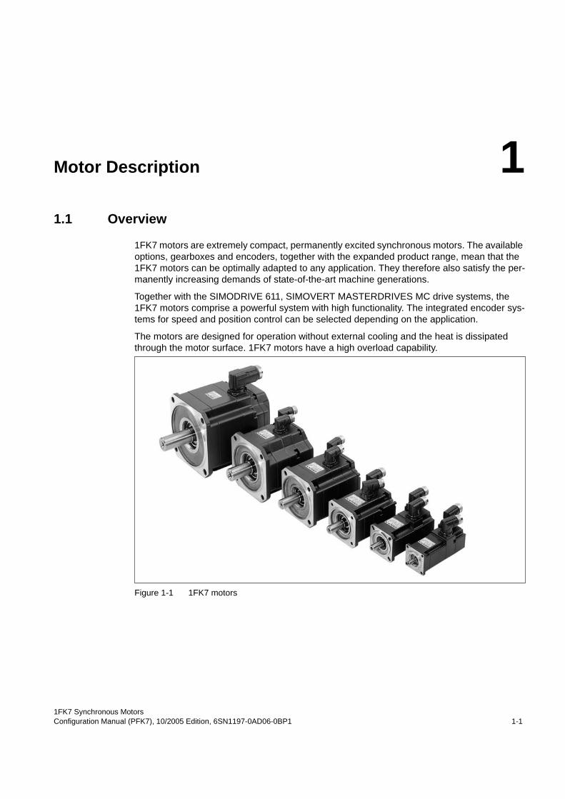
1FK7 motors are extremely compact, permanently excited synchronous motors. The available options, gearboxes and encoders, together with the expanded product range, mean that the 1FK7 motors can be optimally adapted to any application. They therefore also satisfy the per-manently increasing demands of state-of-the-art machine generations.
Together with the SIMODRIVE 611, SIMOVERT MASTERDRIVES MC drive systems, the 1FK7 motors comprise a powerful system with high functionality. The integrated encoder sys-tems for speed and position control can be selected depending on the application.
The motors are designed for operation without external cooling and the heat is dissipated through the motor surface. 1FK7 motors have a high overload capability.
Figure 1-1 1FK7 motorsTable 1-2: Benefits
Motor Description
Technical data
1FK7 Synchronous Motors1-2 Configuration Manual (PFK7), 10/2005 Edition, 6SN1197-0AD06-0BP1
Benefits1FK7 Compact motors offer:
• Space-saving installation thanks to extremely high power/weight ratio
• Can be universally used for many applications
• Wide range of motors
1FK7 High Dynamic motors offer:
• Extremely high dynamic response thanks to low rotor moment of inertiaTable 1-3: Applications
Applications• Machine tools
• Robots and manipulators
• Wood, glass, ceramics and stone working
• Packaging, plastics and textile machines
• Auxiliary axes
1.2 Technical data
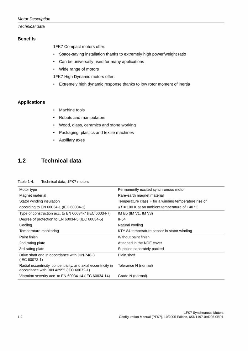
Table 1-4: Technical data, 1FK7 motors
Motor typeMagnet materialStator winding insulationaccording to EN 60034-1 (IEC 60034-1)
Permanently excited synchronous motorRare-earth magnet materialTemperature class F for a winding temperature rise of∆T = 100 K at an ambient temperature of +40 °C
Type of construction acc. to EN 60034-7 (IEC 60034-7)Degree of protection to EN 60034-5 (IEC 60034-5)CoolingTemperature monitoring
IM B5 (IM V1, IM V3)IP64Natural coolingKTY 84 temperature sensor in stator winding
Paint finish2nd rating plate3rd rating plate
Without paint finishAttached in the NDE coverSupplied separately packed
Drive shaft end in accordance with DIN 748-3 (IEC 60072-1)Radial eccentricity, concentricity, and axial eccentricity in accordance with DIN 42955 (IEC 60072-1)Vibration severity acc. to EN 60034-14 (IEC 60034-14)
Plain shaft
Tolerance N (normal)
Grade N (normal)
1FK7 Synchronous MotorsConfiguration Manual (PFK7), 10/2005 Edition, 6SN1197-0AD06-0BP1 1-3
Motor Description
Technical data
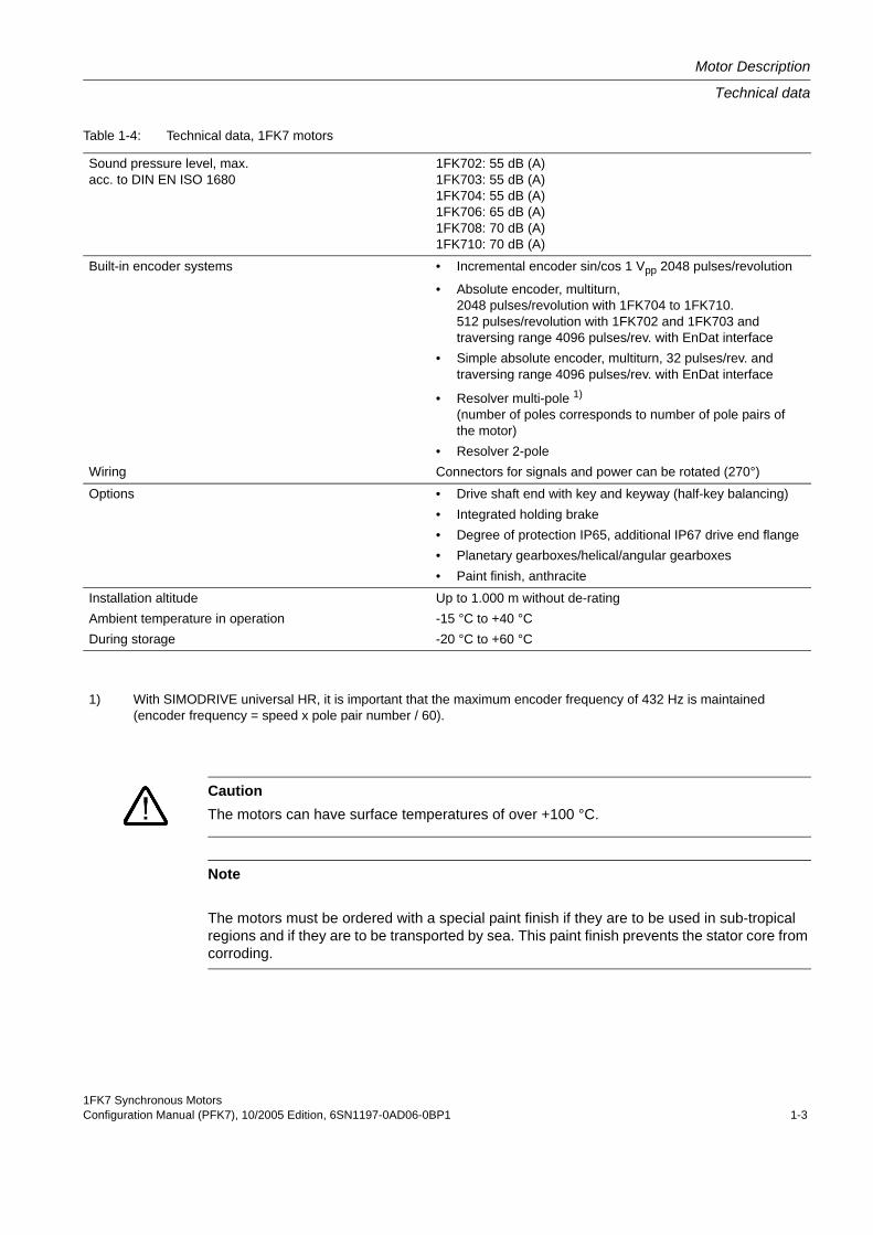
Sound pressure level, max. acc. to DIN EN ISO 1680
1FK702: 55 dB (A)1FK703: 55 dB (A)1FK704: 55 dB (A)1FK706: 65 dB (A)1FK708: 70 dB (A)1FK710: 70 dB (A)
Built-in encoder systems
Wiring
• Incremental encoder sin/cos 1 Vpp 2048 pulses/revolution
• Absolute encoder, multiturn,2048 pulses/revolution with 1FK704 to 1FK710.512 pulses/revolution with 1FK702 and 1FK703 and traversing range 4096 pulses/rev. with EnDat interface
• Simple absolute encoder, multiturn, 32 pulses/rev. andtraversing range 4096 pulses/rev. with EnDat interface
• Resolver multi-pole 1)
(number of poles corresponds to number of pole pairs of the motor)
• Resolver 2-poleConnectors for signals and power can be rotated (270°)
Options • Drive shaft end with key and keyway (half-key balancing)• Integrated holding brake• Degree of protection IP65, additional IP67 drive end flange• Planetary gearboxes/helical/angular gearboxes• Paint finish, anthracite
Installation altitudeAmbient temperature in operationDuring storage
Up to 1.000 m without de-rating -15 °C to +40 °C-20 °C to +60 °C
Table 1-4: Technical data, 1FK7 motors
1) With SIMODRIVE universal HR, it is important that the maximum encoder frequency of 432 Hz is maintained (encoder frequency = speed x pole pair number / 60).
CautionThe motors can have surface temperatures of over +100 °C.
Note
The motors must be ordered with a special paint finish if they are to be used in sub-tropical regions and if they are to be transported by sea. This paint finish prevents the stator core from corroding.
Motor Description
Selection and ordering data
1FK7 Synchronous Motors1-4 Configuration Manual (PFK7), 10/2005 Edition, 6SN1197-0AD06-0BP1
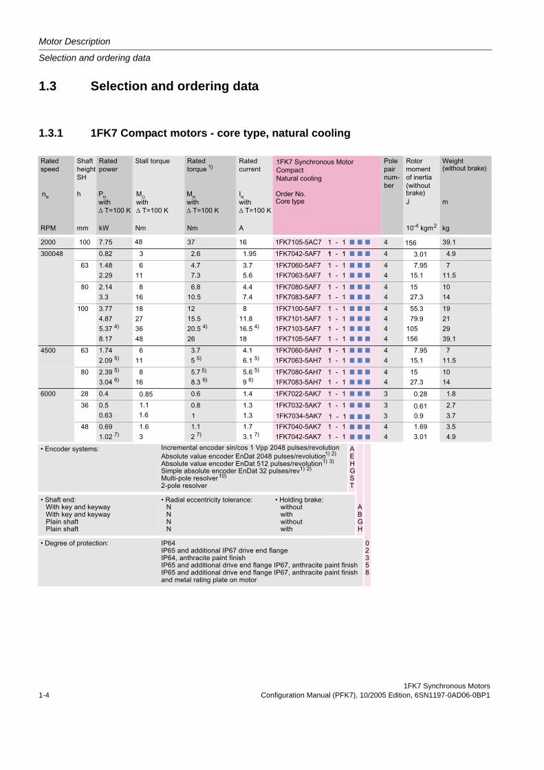
1.3 Selection and ordering data
1.3.1 1FK7 Compact motors - core type, natural cooling
7 7 7
7 7 7
7
7
7
7
7
7
7
7
7
7
7
7
7
7
7
7
7
7
7
7
7
7
7
7
7
7
7
7
7
7
7
7
7
7
7
7
7 7 7
7 7 7
7
7
7
7
7
7
7 7 7
1FK7 Synchronous MotorsConfiguration Manual (PFK7), 10/2005 Edition, 6SN1197-0AD06-0BP1 1-5
Motor Description
Selection and ordering data
7
7
7
7
7
7
7
7
7
7
7
7
7
7
7
7
7
7
7
7 7
Motor Description
Selection and ordering data
1FK7 Synchronous Motors1-6 Configuration Manual (PFK7), 10/2005 Edition, 6SN1197-0AD06-0BP1
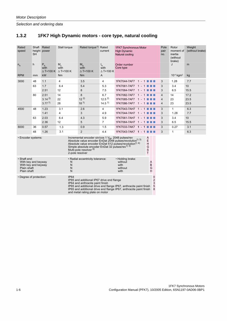
1.3.2 1FK7 High Dynamic motors - core type, natural cooling
7 7 7
7
7
7
7
7
7
7
7
7
7
7
7
7 7 7
7
7
7
7
7
7
7
7
7
7
7
7
7 7 7
7 7 7
1FK7 Synchronous MotorsConfiguration Manual (PFK7), 10/2005 Edition, 6SN1197-0AD06-0BP1 1-7
Motor Description
Selection and ordering data
7
7
7
7
7
7
7
7
7
7
7
7
7 7
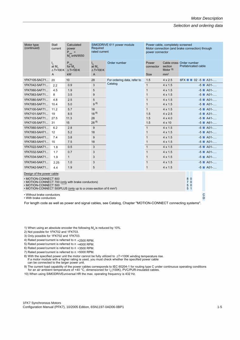
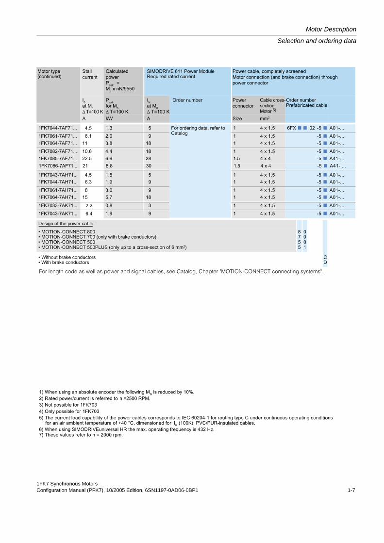
For length code as well as power and signal cables, see Catalog, Chapter "MOTION-CONNECT connecting systems".
Motor Description
Cooling, 1FK7
1FK7 Synchronous Motors1-8 Configuration Manual (PFK7), 10/2005 Edition, 6SN1197-0AD06-0BP1
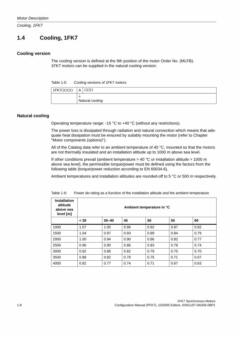
1.4 Cooling, 1FK7
Cooling versionThe cooling version is defined at the 9th position of the motor Order No. (MLFB). 1FK7 motors can be supplied in the natural cooling version:
Natural coolingOperating temperature range: -15 °C to +40 °C (without any restrictions).
The power loss is dissipated through radiation and natural convection which means that ade-quate heat dissipation must be ensured by suitably mounting the motor (refer to Chapter "Motor components (options)").
All of the Catalog data refer to an ambient temperature of 40 °C, mounted so that the motors are not thermally insulated and an installation altitude up to 1000 m above sea level.
If other conditions prevail (ambient temperature > 40 °C or installation altitude > 1000 m above sea level), the permissible torque/power must be defined using the factors from the following table (torque/power reduction according to EN 60034-6).
Ambient temperatures and installation altitudes are rounded-off to 5 °C or 500 m respectively.
Table 1-5: Cooling versions of 1FK7 motors
1FK7 A
↓Natural cooling
Table 1-6: Power de-rating as a function of the installation altitude and the ambient temperature
Installation altitude
above sea level [m]
Ambient temperature in °C
< 30 30–40 45 50 55 60
1000 1.07 1.00 0.96 0.92 0.87 0.82
1500 1.04 0.97 0.93 0.89 0.84 0.79
2000 1.00 0.94 0.90 0.86 0.82 0.77
2500 0.96 0.90 0.86 0.83 0.78 0.74
3000 0.92 0.86 0.82 0.79 0.75 0.70
3500 0.88 0.82 0.79 0.75 0.71 0.67
4000 0.82 0.77 0.74 0.71 0.67 0.63
1FK7 Synchronous MotorsConfiguration Manual (PFK7), 10/2005 Edition, 6SN1197-0AD06-0BP1 1-9
Motor Description
Coupling output
1.5 Coupling output
1.5.1 Description of functionsAfter investigating various coupling outputs for servomotors in conjunction with Siemens drive converters, it was seen, that in many cases, the coupling outputs were the cause of vibration problems. In order to achieve optimum drive output characteristics, ROTEX-GS couplings from the KTR company should be used. The advantages of ROTEX-GS couplings include:
• 2 to 4x torsional stiffness of a belt-driven gearbox
• No intermeshing teeth (when compared to belt gearboxes)
• Low moment of inertia
• Good control behavior
When it comes to mounting, the clamping hub without key is considered to be adequate up to a coupling size of 38 and up to the specified torques that can be transferred (refer to the appropriate motor configuration manual). It must be carefully noted that the friction locked torque must always be adequately dimensioned according to the assignment to the particular motor frame size. The accelerating torque also has to be transferred.
From a coupling size of 42 or as an alternative to the clamping hub, we can recommend the version with clamping ring hub. This means that the maximum coupling torque can be almost reached.
The investigations extend to include the vibration characteristics and behavior. The couplings assigned to the motors permit higher speed control loop gains and therefore result in the highest possible KV values and uniform motion.
ROTEX GS couplings are available with 4 different plastic pinion gears with various Shore hardnesses:
The adaptation to the existing machine masses and stiffness, which becomes possible, must be determined, taking into account the mounted mechanical system.
98 or 95 Shore A (average)
Alternatively: 92 Shore A
Alternatively: 80 Shore A (soft)
Alternatively: 64 Shore D (hard)
Motor Description
Coupling output
1FK7 Synchronous Motors1-10 Configuration Manual (PFK7), 10/2005 Edition, 6SN1197-0AD06-0BP1
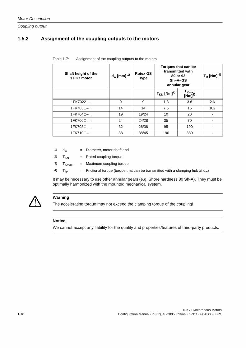
1.5.2 Assignment of the coupling outputs to the motors
It may be necessary to use other annular gears (e.g. Shore hardness 80 Sh-A). They must be optimally harmonized with the mounted mechanical system.
Table 1-7: Assignment of the coupling outputs to the motors
Shaft height of the1 FK7 motor dw [mm] 1) Rotex GS
Type
Torques that can be transmitted with
80 or 92Sh–A–GS
annular gear
TR [Nm] 4)
TKN [Nm]2) TKmax [Nm]3)
1FK7022–... 9 9 1.8 3.6 2.6
1FK703 –... 14 14 7.5 15 102
1FK704 –... 19 19/24 10 20 -
1FK706 –... 24 24/28 35 70 -
1FK708 –... 32 28/38 95 190 -
1FK710 –... 38 38/45 190 380 -
1) dw = Diameter, motor shaft end
2) TKN = Rated coupling torque
3) TKmax = Maximum coupling torque
4) TR: = Frictional torque (torque that can be transmitted with a clamping hub at dw)
WarningThe accelerating torque may not exceed the clamping torque of the coupling!
NoticeWe cannot accept any liability for the quality and properties/features of third-party products.
1FK7 Synchronous MotorsConfiguration Manual (PFK7), 10/2005 Edition, 6SN1197-0AD06-0BP1 1-11
Motor Description
Coupling output
1.5.3 Ordering data
Address: KTRKupplungstechnik GmbHRodder Damm 170D-48432 Rheine
Postal address: Postfach 1763D-48407 Rheine
Tel. engineering Dept.: +49 (0) 5971 / 798 - 465 (337)
Fax: +49 (0) 5971 / 798 - 450
Internet: www.ktr.com
Motor Description
Armature short-circuit braking
1FK7 Synchronous Motors1-12 Configuration Manual (PFK7), 10/2005 Edition, 6SN1197-0AD06-0BP1
1.6 Armature short-circuit braking
1.6.1 Description of functionsFor transistor PWM converters, when the DC link voltage values are exceeded or if the elec-tronics fails, then electrical braking is no longer possible. If the drive which is coasting down, can represent a potential hazard, then the motor can be braked by short-circuiting the arma-ture. Armature short-circuit braking should be initiated at the latest by the limit switch in the traversing range of the feed axis.
The friction of the mechanical system and the switching times of the contactors must be taken into account when determining the distance that the feed axis takes to come to a complete stop. In order to avoid mechanical damage, mechanical stops should be located at the end of the absolute traversing range.
For servomotors with integrated holding brake, the holding brake can be simultaneously applied to create an additional braking torque – however, with some delay.
CautionThe drive converter pulses must first be canceled and this actually implemented before an armature short-circuit contactor is closed or opened. This prevents the contactor contacts from burning and eroding and destroying the drive converter.
WarningThe drive must always be operationally braked using the setpoint input. For additional infor-mation, refer to the Drive Converter Configuration Manual.
1FK7 Synchronous MotorsConfiguration Manual (PFK7), 10/2005 Edition, 6SN1197-0AD06-0BP1 1-13
Motor Description
Armature short-circuit braking
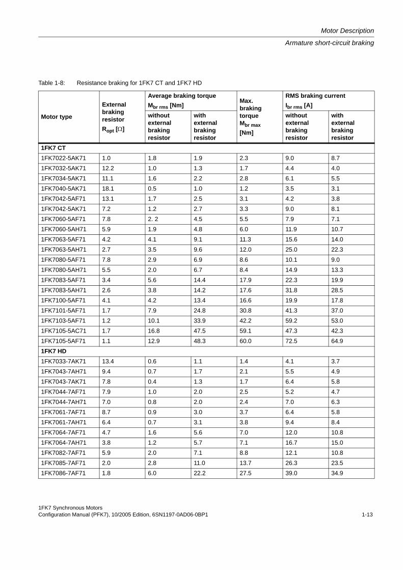
Table 1-8: Resistance braking for 1FK7 CT and 1FK7 HD
Motor type
External braking resistorRopt [Ω]
Average braking torqueMbr rms [Nm]
Max.braking torque Mbr max[Nm]
RMS braking currentIbr rms [A]
without external braking resistor
withexternalbraking resistor
withoutexternalbraking resistor
withexternalbraking resistor
1FK7 CT1FK7022-5AK71 1.0 1.8 1.9 2.3 9.0 8.7
1FK7032-5AK71 12.2 1.0 1.3 1.7 4.4 4.0
1FK7034-5AK71 11.1 1.6 2.2 2.8 6.1 5.5
1FK7040-5AK71 18.1 0.5 1.0 1.2 3.5 3.1
1FK7042-5AF71 13.1 1.7 2.5 3.1 4.2 3.8
1FK7042-5AK71 7.2 1.2 2.7 3.3 9.0 8.1
1FK7060-5AF71 7.8 2. 2 4.5 5.5 7.9 7.1
1FK7060-5AH71 5.9 1.9 4.8 6.0 11.9 10.7
1FK7063-5AF71 4.2 4.1 9.1 11.3 15.6 14.0
1FK7063-5AH71 2.7 3.5 9.6 12.0 25.0 22.3
1FK7080-5AF71 7.8 2.9 6.9 8.6 10.1 9.0
1FK7080-5AH71 5.5 2.0 6.7 8.4 14.9 13.3
1FK7083-5AF71 3.4 5.6 14.4 17.9 22.3 19.9
1FK7083-5AH71 2.6 3.8 14.2 17.6 31.8 28.5
1FK7100-5AF71 4.1 4.2 13.4 16.6 19.9 17.8
1FK7101-5AF71 1.7 7.9 24.8 30.8 41.3 37.0
1FK7103-5AF71 1.2 10.1 33.9 42.2 59.2 53.0
1FK7105-5AC71 1.7 16.8 47.5 59.1 47.3 42.3
1FK7105-5AF71 1.1 12.9 48.3 60.0 72.5 64.9
1FK7 HD1FK7033-7AK71 13.4 0.6 1.1 1.4 4.1 3.7
1FK7043-7AH71 9.4 0.7 1.7 2.1 5.5 4.9
1FK7043-7AK71 7.8 0.4 1.3 1.7 6.4 5.8
1FK7044-7AF71 7.9 1.0 2.0 2.5 5.2 4.7
1FK7044-7AH71 7.0 0.8 2.0 2.4 7.0 6.3
1FK7061-7AF71 8.7 0.9 3.0 3.7 6.4 5.8
1FK7061-7AH71 6.4 0.7 3.1 3.8 9.4 8.4
1FK7064-7AF71 4.7 1.6 5.6 7.0 12.0 10.8
1FK7064-7AH71 3.8 1.2 5.7 7.1 16.7 15.0
1FK7082-7AF71 5.9 2.0 7.1 8.8 12.1 10.8
1FK7085-7AF71 2.0 2.8 11.0 13.7 26.3 23.5
1FK7086-7AF71 1.8 6.0 22.2 27.5 39.0 34.9
Motor Description
Armature short-circuit braking
1FK7 Synchronous Motors1-14 Configuration Manual (PFK7), 10/2005 Edition, 6SN1197-0AD06-0BP1
Ordering address
Ordering address: Fritzlen GmbH & Co.KGGottlieb-Daimler-Str. 61D-71711 MurrGermany
Tel. : +49 (0) 7144 / 2724 - 25
1FK7 Synchronous MotorsConfiguration Manual (PFK7), 10/2005 Edition, 6SN1197-0AD06-0BP1 2-1
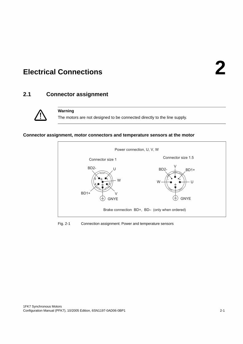
Electrical Connections 22.1 Connector assignment
Connector assignment, motor connectors and temperature sensors at the motor
Fig. 2-1 Connection assignment: Power and temperature sensors
WarningThe motors are not designed to be connected directly to the line supply.
1
24
5 6 - +
Electrical Connections
Rotating the connector at the motor
1FK7 Synchronous Motors2-2 Configuration Manual (PFK7), 10/2005 Edition, 6SN1197-0AD06-0BP1
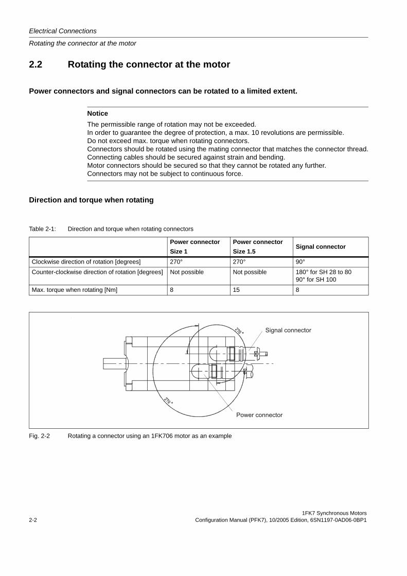
2.2 Rotating the connector at the motor
Power connectors and signal connectors can be rotated to a limited extent.
Direction and torque when rotating
Fig. 2-2 Rotating a connector using an 1FK706 motor as an example
NoticeThe permissible range of rotation may not be exceeded.In order to guarantee the degree of protection, a max. 10 revolutions are permissible.Do not exceed max. torque when rotating connectors.Connectors should be rotated using the mating connector that matches the connector thread.Connecting cables should be secured against strain and bending.Motor connectors should be secured so that they cannot be rotated any further.Connectors may not be subject to continuous force.
Table 2-1: Direction and torque when rotating connectors
Power connectorSize 1
Power connectorSize 1.5
Signal connector
Clockwise direction of rotation [degrees] 270° 270° 90°
Counter-clockwise direction of rotation [degrees] Not possible Not possible 180° for SH 28 to 8090° for SH 100
Max. torque when rotating [Nm] 8 15 8
1FK7 Synchronous MotorsConfiguration Manual (PFK7), 10/2005 Edition, 6SN1197-0AD06-0BP1 3-1
Technical Data and Characteristics 33.1 Introduction
NoteFor converter operation on 480 V line supplies, DC link voltages greater than 600 V occur. The motors are suitable for DC link voltages up to 740 V.
For a description of the shift of the voltage limiting characteristics, refer to the documentation "General Section for synchronous motors".
The specified thermal S3 limiting characteristics are referred to ∆T = 100 K for
- 1 min cycle duration for SH 28 and 36- 10 min cycle duration for SH 48, 63, 80, 100
Technical Data and Characteristics
Speed-torque diagrams 1FK7 CT
1FK7 Synchronous Motors3-2 Configuration Manual (PFK7), 10/2005 Edition, 6SN1197-0AD06-0BP1
3.2 Speed-torque diagrams 1FK7 CT
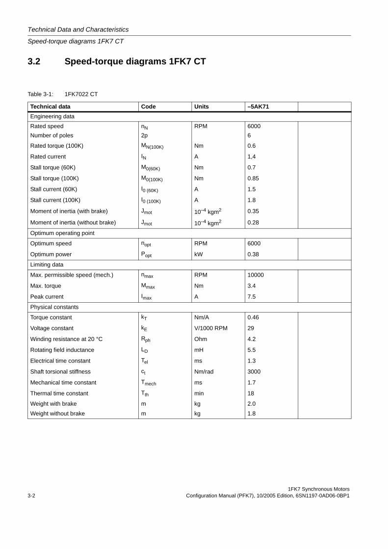
Table 3-1: 1FK7022 CT
Technical data Code Units –5AK71Engineering data
Rated speed nN RPM 6000 Number of poles 2p 6
Rated torque (100K) MN(100K) Nm 0.6
Rated current IN A 1,4
Stall torque (60K) M0(60K) Nm 0.7
Stall torque (100K) M0(100K) Nm 0.85
Stall current (60K) I0 (60K) A 1.5
Stall current (100K) I0 (100K) A 1.8
Moment of inertia (with brake) Jmot 10–4 kgm2 0.35
Moment of inertia (without brake) Jmot 10–4 kgm2 0.28
Optimum operating point
Optimum speed nopt RPM 6000
Optimum power Popt kW 0.38
Limiting data
Max. permissible speed (mech.) nmax RPM 10000
Max. torque Mmax Nm 3.4
Peak current Imax A 7.5
Physical constants
Torque constant kT Nm/A 0.46
Voltage constant kE V/1000 RPM 29
Winding resistance at 20 °C Rph Ohm 4.2
Rotating field inductance LD mH 5.5
Electrical time constant Tel ms 1.3
Shaft torsional stiffness ct Nm/rad 3000
Mechanical time constant Tmech ms 1.7
Thermal time constant Tth min 18
Weight with brake m kg 2.0
Weight without brake m kg 1.8
1FK7 Synchronous MotorsConfiguration Manual (PFK7), 10/2005 Edition, 6SN1197-0AD06-0BP1 3-3
Technical Data and Characteristics
Speed-torque diagrams 1FK7 CT
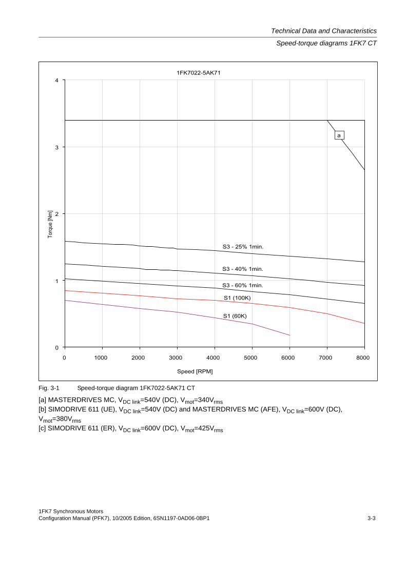
Fig. 3-1 Speed-torque diagram 1FK7022-5AK71 CT
[a] MASTERDRIVES MC, VDC link=540V (DC), Vmot=340Vrms[b] SIMODRIVE 611 (UE), VDC link=540V (DC) and MASTERDRIVES MC (AFE), VDC link=600V (DC), Vmot=380Vrms[c] SIMODRIVE 611 (ER), VDC link=600V (DC), Vmot=425Vrms
Technical Data and Characteristics
Speed-torque diagrams 1FK7 CT
1FK7 Synchronous Motors3-4 Configuration Manual (PFK7), 10/2005 Edition, 6SN1197-0AD06-0BP1
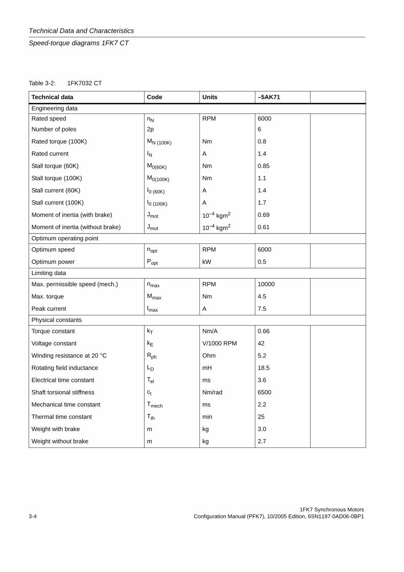
Table 3-2: 1FK7032 CT
Technical data Code Units –5AK71
Engineering data
Rated speed nN RPM 6000
Number of poles 2p 6
Rated torque (100K) MN (100K) Nm 0.8
Rated current IN A 1.4
Stall torque (60K) M0(60K) Nm 0.85
Stall torque (100K) M0(100K) Nm 1.1
Stall current (60K) I0 (60K) A 1.4
Stall current (100K) I0 (100K) A 1.7
Moment of inertia (with brake) Jmot 10–4 kgm2 0.69
Moment of inertia (without brake) Jmot 10–4 kgm2 0.61
Optimum operating point
Optimum speed nopt RPM 6000
Optimum power Popt kW 0.5
Limiting data
Max. permissible speed (mech.) nmax RPM 10000
Max. torque Mmax Nm 4.5
Peak current Imax A 7.5
Physical constants
Torque constant kT Nm/A 0.66
Voltage constant kE V/1000 RPM 42
Winding resistance at 20 °C Rph Ohm 5.2
Rotating field inductance LD mH 18.5
Electrical time constant Tel ms 3.6
Shaft torsional stiffness ct Nm/rad 6500
Mechanical time constant Tmech ms 2.2
Thermal time constant Tth min 25
Weight with brake m kg 3.0
Weight without brake m kg 2.7
1FK7 Synchronous MotorsConfiguration Manual (PFK7), 10/2005 Edition, 6SN1197-0AD06-0BP1 3-5
Technical Data and Characteristics
Speed-torque diagrams 1FK7 CT
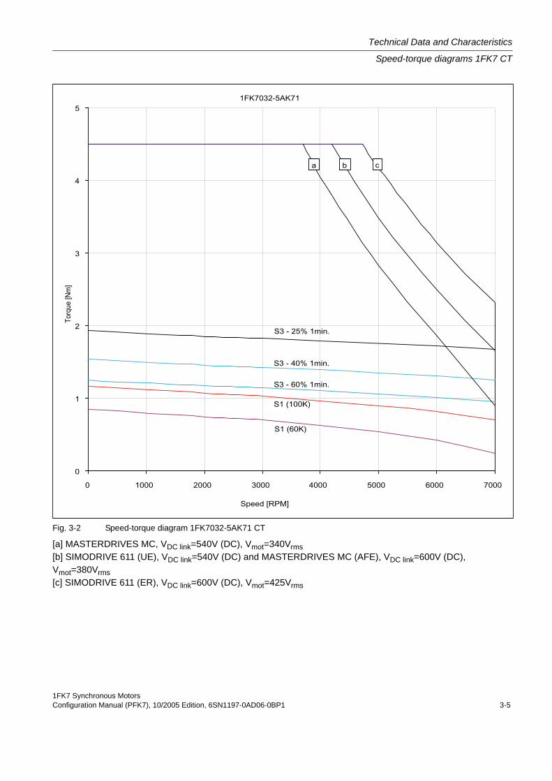
Fig. 3-2 Speed-torque diagram 1FK7032-5AK71 CT
[a] MASTERDRIVES MC, VDC link=540V (DC), Vmot=340Vrms[b] SIMODRIVE 611 (UE), VDC link=540V (DC) and MASTERDRIVES MC (AFE), VDC link=600V (DC), Vmot=380Vrms[c] SIMODRIVE 611 (ER), VDC link=600V (DC), Vmot=425Vrms

Technical Data and Characteristics
Speed-torque diagrams 1FK7 CT
1FK7 Synchronous Motors3-6 Configuration Manual (PFK7), 10/2005 Edition, 6SN1197-0AD06-0BP1
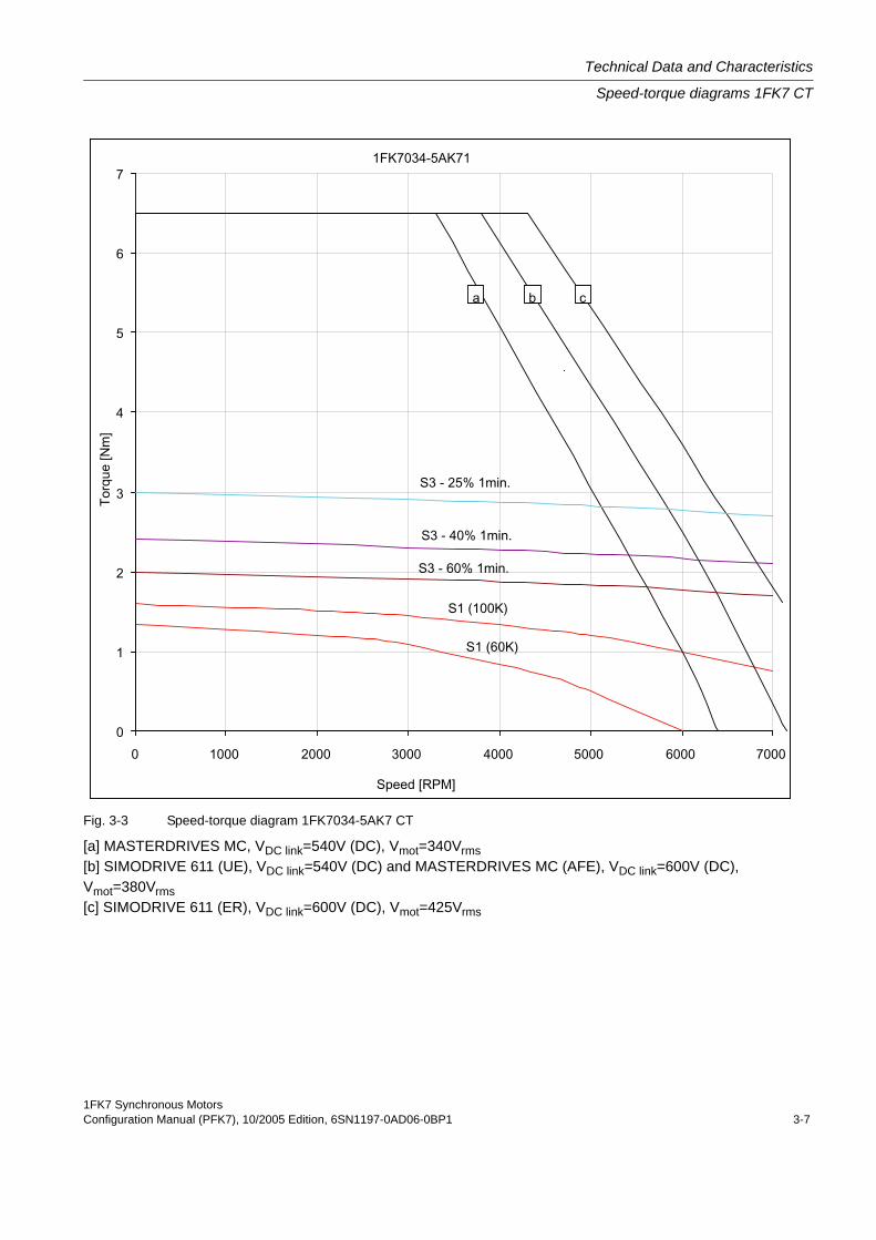
Table 3-3: 1FK7034 CT
Technical data Code Units –5AK71
Engineering data
Rated speed nN RPM 6000
Number of poles 2p 6
Rated torque (100K) MN(100K) Nm 1
Rated current IN A 1.3
Stall torque (60K) M0(60K) Nm 1.35
Stall torque (100K) M0(100K) Nm 1.6
Stall current (60K) I0 (60K) A 1.6
Stall current (100K) I0 (100K) A 1.9
Moment of inertia (with brake) Jmot 10–4 kgm2 0.98
Moment of inertia (without brake) Jmot 10–4 kgm2 0.9
Optimum operating point
Optimum speed nopt RPM 6000
Optimum power Popt kW 0.63
Limiting data
Max. permissible speed (mech.) nmax RPM 10000
Max. torque Mmax Nm 6.5
Peak current Imax A 8
Physical constants
Torque constant kT Nm/A 0.86
Voltage constant kE V/1000 RPM 55
Winding resistance at 20 °C Rph Ohm 4.5
Rotating field inductance LD mH 16.5
Electrical time constant Tel ms 3.7
Shaft torsional stiffness ct Nm/rad 5500
Mechanical time constant Tmech ms 1.6
Thermal time constant Tth min 30
Weight with brake m kg 4.0
Weight without brake m kg 3.7
1FK7 Synchronous MotorsConfiguration Manual (PFK7), 10/2005 Edition, 6SN1197-0AD06-0BP1 3-7
Technical Data and Characteristics
Speed-torque diagrams 1FK7 CT
Fig. 3-3 Speed-torque diagram 1FK7034-5AK7 CT
[a] MASTERDRIVES MC, VDC link=540V (DC), Vmot=340Vrms[b] SIMODRIVE 611 (UE), VDC link=540V (DC) and MASTERDRIVES MC (AFE), VDC link=600V (DC), Vmot=380Vrms[c] SIMODRIVE 611 (ER), VDC link=600V (DC), Vmot=425Vrms
Technical Data and Characteristics
Speed-torque diagrams 1FK7 CT
1FK7 Synchronous Motors3-8 Configuration Manual (PFK7), 10/2005 Edition, 6SN1197-0AD06-0BP1
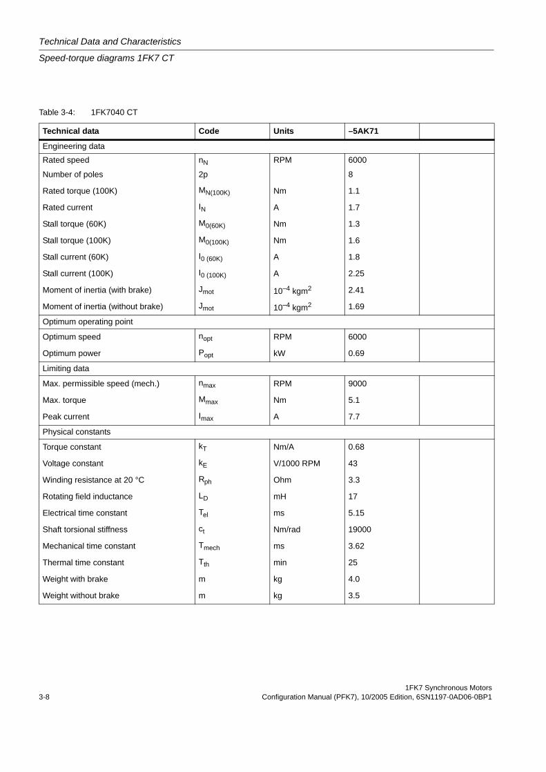
Table 3-4: 1FK7040 CT
Technical data Code Units –5AK71
Engineering data
Rated speed nN RPM 6000
Number of poles 2p 8
Rated torque (100K) MN(100K) Nm 1.1
Rated current IN A 1.7
Stall torque (60K) M0(60K) Nm 1.3
Stall torque (100K) M0(100K) Nm 1.6
Stall current (60K) I0 (60K) A 1.8
Stall current (100K) I0 (100K) A 2.25
Moment of inertia (with brake) Jmot 10–4 kgm2 2.41
Moment of inertia (without brake) Jmot 10–4 kgm2 1.69
Optimum operating point
Optimum speed nopt RPM 6000
Optimum power Popt kW 0.69
Limiting data
Max. permissible speed (mech.) nmax RPM 9000
Max. torque Mmax Nm 5.1
Peak current Imax A 7.7
Physical constants
Torque constant kT Nm/A 0.68
Voltage constant kE V/1000 RPM 43
Winding resistance at 20 °C Rph Ohm 3.3
Rotating field inductance LD mH 17
Electrical time constant Tel ms 5.15
Shaft torsional stiffness ct Nm/rad 19000
Mechanical time constant Tmech ms 3.62
Thermal time constant Tth min 25
Weight with brake m kg 4.0
Weight without brake m kg 3.5
1FK7 Synchronous MotorsConfiguration Manual (PFK7), 10/2005 Edition, 6SN1197-0AD06-0BP1 3-9
Technical Data and Characteristics
Speed-torque diagrams 1FK7 CT
Fig. 3-4 Speed-torque diagram 1FK7040-5AK71 CT
[a] MASTERDRIVES MC, VDC link=540V (DC), Vmot=340Vrms[b] SIMODRIVE 611 (UE), VDC link=540V (DC) and MASTERDRIVES MC (AFE), VDC link=600V (DC), Vmot=380Vrms[c] SIMODRIVE 611 (ER), VDC link=600V (DC), Vmot=425Vrms

Technical Data and Characteristics
Speed-torque diagrams 1FK7 CT
1FK7 Synchronous Motors3-10 Configuration Manual (PFK7), 10/2005 Edition, 6SN1197-0AD06-0BP1
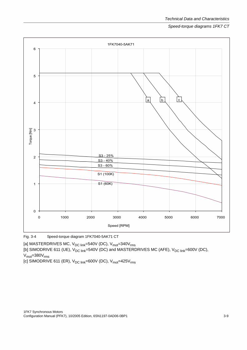
Table 3-5: 1FK7042 CT
Technical data Code Units –5AF71 –5AK71Engineering data
Rated speed nN RPM 3000 6000Number of poles 2p 8 8
Rated torque (100K) MN(100K) Nm 2.6 1.5
Rated current IN A 1.95 2.45
Stall torque (60K) M0(60K) Nm 2.5 2.5
Stall torque (100K) M0(100K) Nm 3.0 3.0
Stall current (60K) I0 (60K) A 1.8 3.6
Stall current (100K) I0 (100K) A 2.2 4.4
Moment of inertia (with brake) Jmot 10–4 kgm2 3.73 3.73
Moment of inertia (without brake) Jmot 10–4 kgm2 3.01 3.01
Optimum operating point
Optimum speed nopt RPM 3000 5000
Optimum power Popt kW 0.82 1.02
Limiting data
Max. permissible speed (mech.) nmax RPM 90000 9000
Max. torque Mmax Nm 10.5 10.5
Peak current Imax A 7.35 15.3
Physical constants
Torque constant kT Nm/A 1.4 0.69
Voltage constant kE V/1000 RPM 89 44
Winding resistance at 20 °C Rph Ohm 5.15 1.2
Rotating field inductance LD mH 29 6.7
Electrical time constant Tel ms 5.6 5.6
Shaft torsional stiffness ct Nm/rad 16000 16000
Mechanical time constant Tmech ms 2.37 2.27
Thermal time constant Tth min 30 30
Weight with brake m kg 5.4 5.4
Weight without brake m kg 4.9 4.9
1FK7 Synchronous MotorsConfiguration Manual (PFK7), 10/2005 Edition, 6SN1197-0AD06-0BP1 3-11
Technical Data and Characteristics
Speed-torque diagrams 1FK7 CT
Fig. 3-5 Speed-torque diagram 1FK7042-5AF71 CT
Fig. 3-6 Speed-torque diagram 1FK7042-5AK71 CT
[a] MASTERDRIVES MC, VDC link=540V (DC), Vmot=340Vrms[b] SIMODRIVE 611 (UE), VDC link=540V (DC) and MASTERDRIVES MC (AFE), VDC link=600V (DC), Vmot=380Vrms[c] SIMODRIVE 611 (ER), VDC link=600V (DC), Vmot=425Vrms

Technical Data and Characteristics
Speed-torque diagrams 1FK7 CT
1FK7 Synchronous Motors3-12 Configuration Manual (PFK7), 10/2005 Edition, 6SN1197-0AD06-0BP1
Table 3-6: 1FK7060 CT
Technical data Code Units –5AF71 –5AH71Engineering data
Rated speed nN RPM 3000 4500Number of poles 2p 8 8
Rated torque (100K) MN(100K) Nm 4.7 3.7
Rated current IN A 3.7 4.1
Stall torque (60K) M0(60K) Nm 5.0 5.0
Stall torque (100K) M0(100K) Nm 6.0 6.0
Stall current (60K) I0 (60K) A 3.7 5.1
Stall current (100K) I0 (100K) A 4.5 6.2
Moment of inertia (with brake) Jmot 10–4 kgm2 10.2 10.2
Moment of inertia (without brake) Jmot 10–4 kgm2 7.95 7.95
Optimum operating point
Optimum speed nopt RPM 3000 4500
Optimum power Popt kW 1.48 1.74
Limiting data
Max. permissible speed (mech.) nmax RPM 7200 7200
Max. torque Mmax Nm 18 18
Peak current Imax A 15 19.5
Physical constants
Torque constant kT Nm/A 1.33 0.95
Voltage constant kE V/1000 RPM 84.5 60.5
Winding resistance at 20 °C Rph Ohm 1.44 0.73
Rotating field inductance LD mH 14.7 7.0
Electrical time constant Tel ms 10.2 9.6
Shaft torsional stiffness ct Nm/rad 42000 42000
Mechanical time constant Tmech ms 1.94 1.93
Thermal time constant Tth min 30 30
Weight with brake m kg 8 8
Weight without brake m kg 7 7
1FK7 Synchronous MotorsConfiguration Manual (PFK7), 10/2005 Edition, 6SN1197-0AD06-0BP1 3-13
Technical Data and Characteristics
Speed-torque diagrams 1FK7 CT
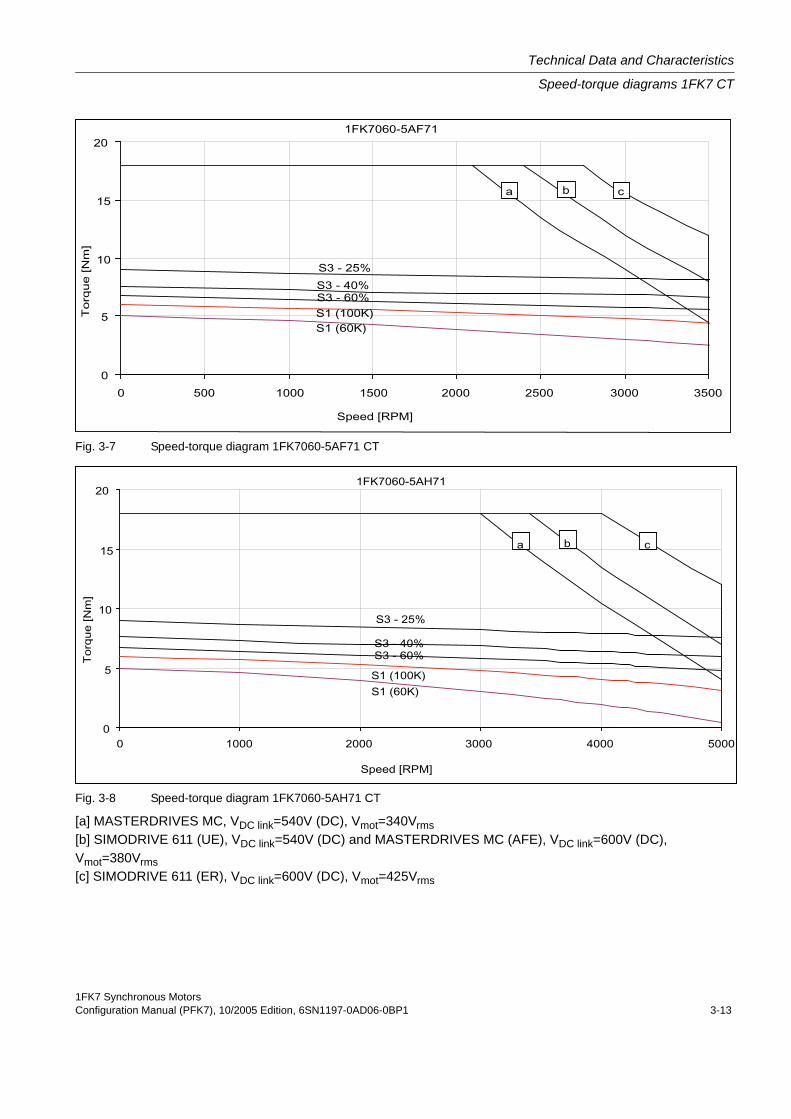
Fig. 3-7 Speed-torque diagram 1FK7060-5AF71 CT
Fig. 3-8 Speed-torque diagram 1FK7060-5AH71 CT
[a] MASTERDRIVES MC, VDC link=540V (DC), Vmot=340Vrms[b] SIMODRIVE 611 (UE), VDC link=540V (DC) and MASTERDRIVES MC (AFE), VDC link=600V (DC), Vmot=380Vrms[c] SIMODRIVE 611 (ER), VDC link=600V (DC), Vmot=425Vrms

Technical Data and Characteristics
Speed-torque diagrams 1FK7 CT
1FK7 Synchronous Motors3-14 Configuration Manual (PFK7), 10/2005 Edition, 6SN1197-0AD06-0BP1
Table 3-7: 1FK7063 CT
Technical data Code Units –5AF71 –5AH71Engineering data
Rated speed nN RPM 3000 4500Number of poles 2p 8 8
Rated torque (100K) MN(100K) Nm 7.3 3
Rated current IN A 5.6 3.8
Stall torque (60K) M0(60K) Nm 9.1 9.1
Stall torque (100K) M0(100K) Nm 11 11
Stall current (60K) I0 (60K) A 6.6 9.9
Stall current (100K) I0 (100K) A 8.0 12.0
Moment of inertia (with brake) Jmot 10–4 kgm2 17.3 17.3
Moment of inertia (without brake) Jmot 10–4 kgm2 15.1 15.1
Optimum operating point
Optimum speed nopt RPM 3000 3300
Optimum power Popt kW 2.29 2.32
Limiting data
Max. permissible speed (mech.) nmax RPM 7200 7200
Max. torque Mmax Nm 35 35
Peak current Imax A 28 42
Physical constants
Torque constant kT Nm/A 1.37 0.91
Voltage constant kE V/1000 RPM 87.5 58
Winding resistance at 20 °C Rph Ohm 0.65 0.29
Rotating field inductance LD mH 7.7 3.2
Electrical time constant Tel ms 11.8 11
Shaft torsional stiffness ct Nm/rad 35000 35000
Mechanical time constant Tmech ms 1.56 1.58
Thermal time constant Tth min 40 40
Weight with brake m kg 12 12
Weight without brake m kg 11.5 11.5
1FK7 Synchronous MotorsConfiguration Manual (PFK7), 10/2005 Edition, 6SN1197-0AD06-0BP1 3-15
Technical Data and Characteristics
Speed-torque diagrams 1FK7 CT
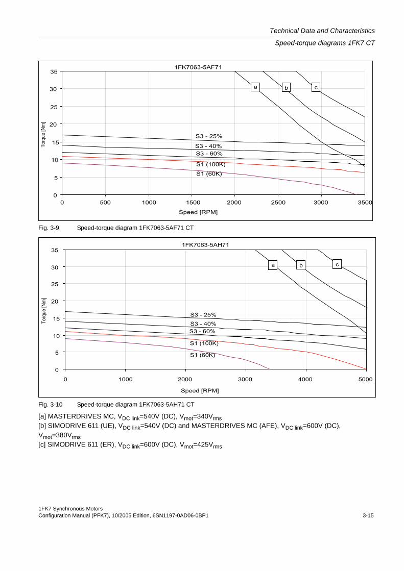
Fig. 3-9 Speed-torque diagram 1FK7063-5AF71 CT
Fig. 3-10 Speed-torque diagram 1FK7063-5AH71 CT
[a] MASTERDRIVES MC, VDC link=540V (DC), Vmot=340Vrms[b] SIMODRIVE 611 (UE), VDC link=540V (DC) and MASTERDRIVES MC (AFE), VDC link=600V (DC), Vmot=380Vrms[c] SIMODRIVE 611 (ER), VDC link=600V (DC), Vmot=425Vrms

Technical Data and Characteristics
Speed-torque diagrams 1FK7 CT
1FK7 Synchronous Motors3-16 Configuration Manual (PFK7), 10/2005 Edition, 6SN1197-0AD06-0BP1
Table 3-8: 1FK7080 CT
Technical data Code Units –5AF71 –5AH71Engineering data
Rated speed nN RPM 3000 4500Number of poles 2p 8 8
Rated torque (100K) MN(100K) Nm 6.8 4.5
Rated current IN A 4.4 4.7
Stall torque (60K) M0(60K) Nm 6.6 6.6
Stall torque (100K) M0(100K) Nm 8 8
Stall current (60K) I0 (60K) A 4 6.1
Stall current (100K) I0 (100K) A 4.8 7.4
Moment of inertia (with brake) Jmot 10–4 kgm2 18.1 18.1
Moment of inertia (without brake) Jmot 10–4 kgm2 15 15
Optimum operating point
Optimum speed nopt RPM 3000 4000
Optimum power Popt kW 2.14 2.39
Limiting data
Max. permissible speed (mech.) nmax RPM 6000 6000
Max. torque Mmax Nm 25 25
Peak current Imax A 18 25
Physical constants
Torque constant kT Nm/A 1.61 1.06
Voltage constant kE V/1000 RPM 102.5 68.0
Winding resistance at 20 °C Rph Ohm 1.04 0.44
Rotating field inductance LD mH 14.0 6.3
Electrical time constant Tel ms 13.5 14.3
Shaft torsional stiffness ct Nm/rad 126000 126000
Mechanical time constant Tmech ms 1.78 1.76
Thermal time constant Tth min 40 40
Weight with brake m kg 12.5 12.5
Weight without brake m kg 10 10
1FK7 Synchronous MotorsConfiguration Manual (PFK7), 10/2005 Edition, 6SN1197-0AD06-0BP1 3-17
Technical Data and Characteristics
Speed-torque diagrams 1FK7 CT
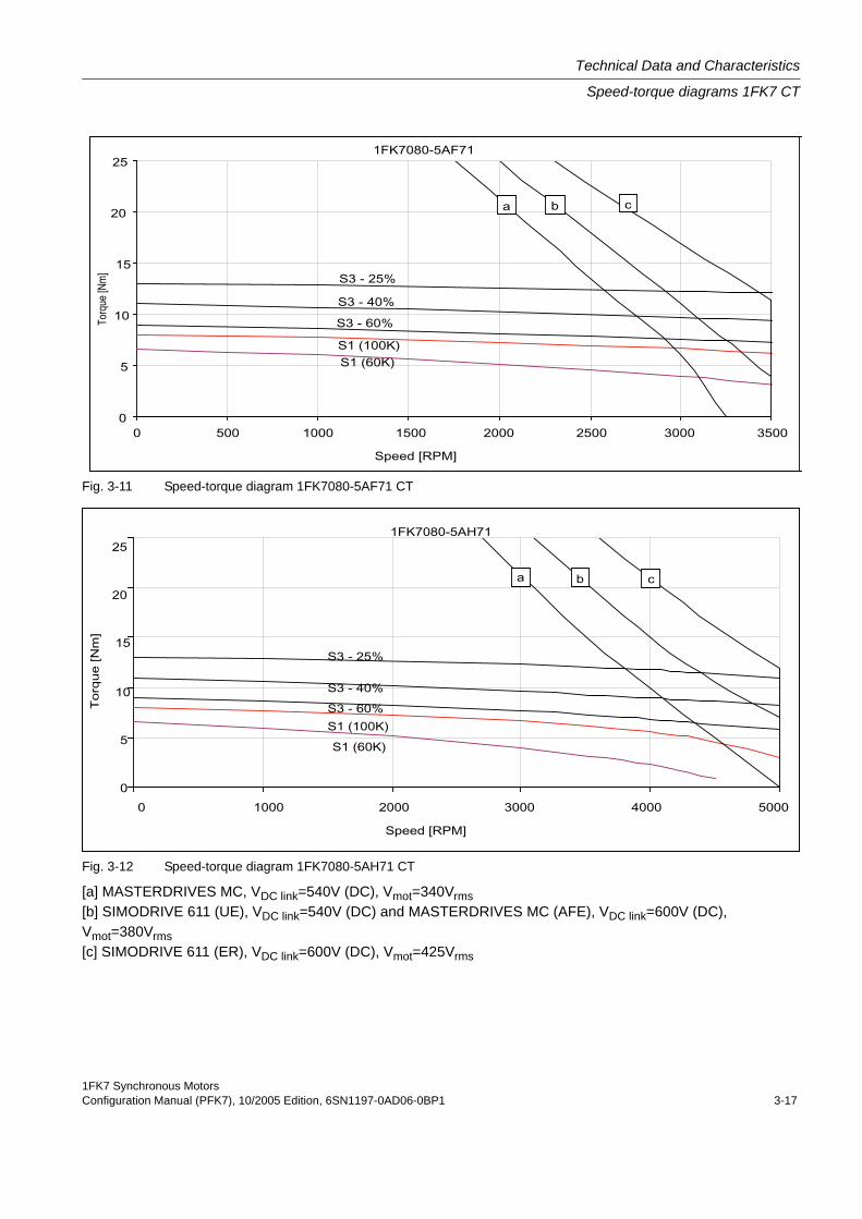
Fig. 3-11 Speed-torque diagram 1FK7080-5AF71 CT
Fig. 3-12 Speed-torque diagram 1FK7080-5AH71 CT
[a] MASTERDRIVES MC, VDC link=540V (DC), Vmot=340Vrms[b] SIMODRIVE 611 (UE), VDC link=540V (DC) and MASTERDRIVES MC (AFE), VDC link=600V (DC), Vmot=380Vrms[c] SIMODRIVE 611 (ER), VDC link=600V (DC), Vmot=425Vrms
Technical Data and Characteristics
Speed-torque diagrams 1FK7 CT
1FK7 Synchronous Motors3-18 Configuration Manual (PFK7), 10/2005 Edition, 6SN1197-0AD06-0BP1
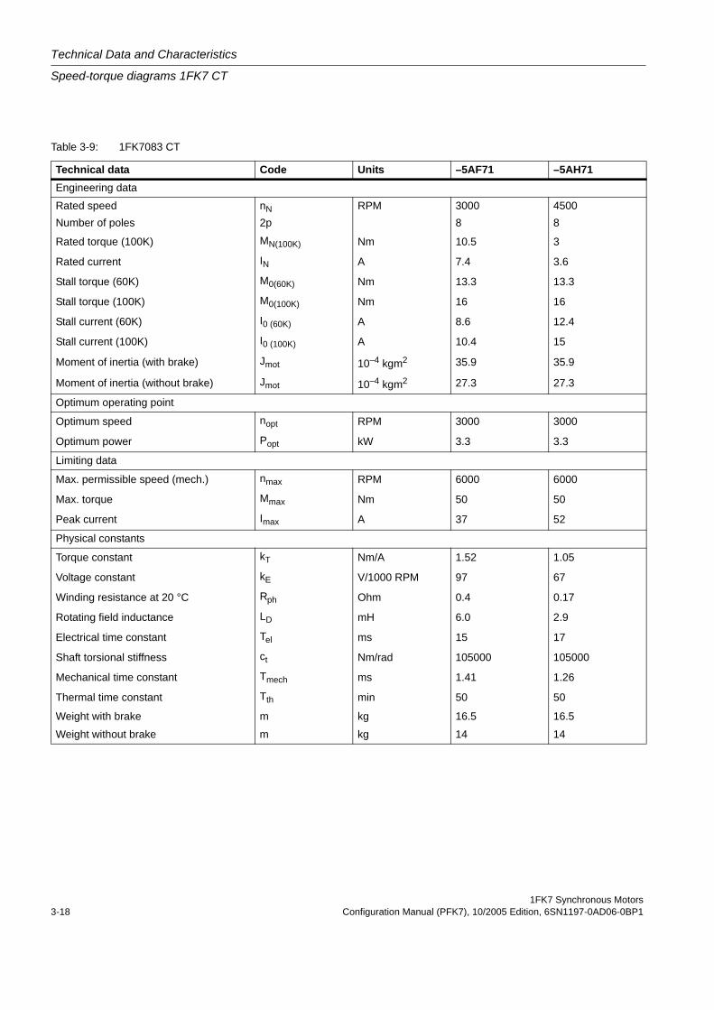
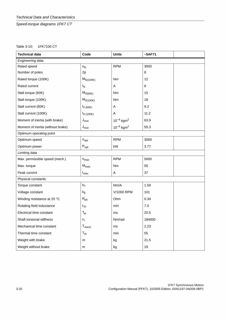
Table 3-9: 1FK7083 CT
Technical data Code Units –5AF71 –5AH71Engineering data
Rated speed nN RPM 3000 4500Number of poles 2p 8 8
Rated torque (100K) MN(100K) Nm 10.5 3
Rated current IN A 7.4 3.6
Stall torque (60K) M0(60K) Nm 13.3 13.3
Stall torque (100K) M0(100K) Nm 16 16
Stall current (60K) I0 (60K) A 8.6 12.4
Stall current (100K) I0 (100K) A 10.4 15
Moment of inertia (with brake) Jmot 10–4 kgm2 35.9 35.9
Moment of inertia (without brake) Jmot 10–4 kgm2 27.3 27.3
Optimum operating point
Optimum speed nopt RPM 3000 3000
Optimum power Popt kW 3.3 3.3
Limiting data
Max. permissible speed (mech.) nmax RPM 6000 6000
Max. torque Mmax Nm 50 50
Peak current Imax A 37 52
Physical constants
Torque constant kT Nm/A 1.52 1.05
Voltage constant kE V/1000 RPM 97 67
Winding resistance at 20 °C Rph Ohm 0.4 0.17
Rotating field inductance LD mH 6.0 2.9
Electrical time constant Tel ms 15 17
Shaft torsional stiffness ct Nm/rad 105000 105000
Mechanical time constant Tmech ms 1.41 1.26
Thermal time constant Tth min 50 50
Weight with brake m kg 16.5 16.5
Weight without brake m kg 14 14
1FK7 Synchronous MotorsConfiguration Manual (PFK7), 10/2005 Edition, 6SN1197-0AD06-0BP1 3-19
Technical Data and Characteristics
Speed-torque diagrams 1FK7 CT
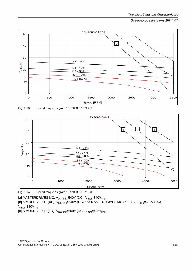
Fig. 3-13 Speed-torque diagram 1FK7083-5AF71 CT
Fig. 3-14 Speed-torque diagram 1FK7083-5AH71 CT
[a] MASTERDRIVES MC, VDC link=540V (DC), Vmot=340Vrms[b] SIMODRIVE 611 (UE), VDC link=540V (DC) and MASTERDRIVES MC (AFE), VDC link=600V (DC), Vmot=380Vrms[c] SIMODRIVE 611 (ER), VDC link=600V (DC), Vmot=425Vrms
Technical Data and Characteristics
Speed-torque diagrams 1FK7 CT
1FK7 Synchronous Motors3-20 Configuration Manual (PFK7), 10/2005 Edition, 6SN1197-0AD06-0BP1
Table 3-10: 1FK7100 CT
Technical data Code Units –5AF71
Engineering data
Rated speed nN RPM 3000
Number of poles 2p 8
Rated torque (100K) MN(100K) Nm 12
Rated current IN A 8
Stall torque (60K) M0(60K) Nm 15
Stall torque (100K) M0(100K) Nm 18
Stall current (60K) I0 (60K) A 9.2
Stall current (100K) I0 (100K) A 11.2
Moment of inertia (with brake) Jmot 10–4 kgm2 63.9
Moment of inertia (without brake) Jmot 10–4 kgm2 55.3
Optimum operating point
Optimum speed nopt RPM 3000
Optimum power Popt kW 3.77
Limiting data
Max. permissible speed (mech.) nmax RPM 5000
Max. torque Mmax Nm 55
Peak current Imax A 37
Physical constants
Torque constant kT Nm/A 1.59
Voltage constant kE V/1000 RPM 101
Winding resistance at 20 °C Rph Ohm 0.34
Rotating field inductance LD mH 7.0
Electrical time constant Tel ms 20.5
Shaft torsional stiffness ct Nm/rad 184000
Mechanical time constant Tmech ms 2.23
Thermal time constant Tth min 55
Weight with brake m kg 21.5
Weight without brake m kg 19
1FK7 Synchronous MotorsConfiguration Manual (PFK7), 10/2005 Edition, 6SN1197-0AD06-0BP1 3-21
Technical Data and Characteristics
Speed-torque diagrams 1FK7 CT
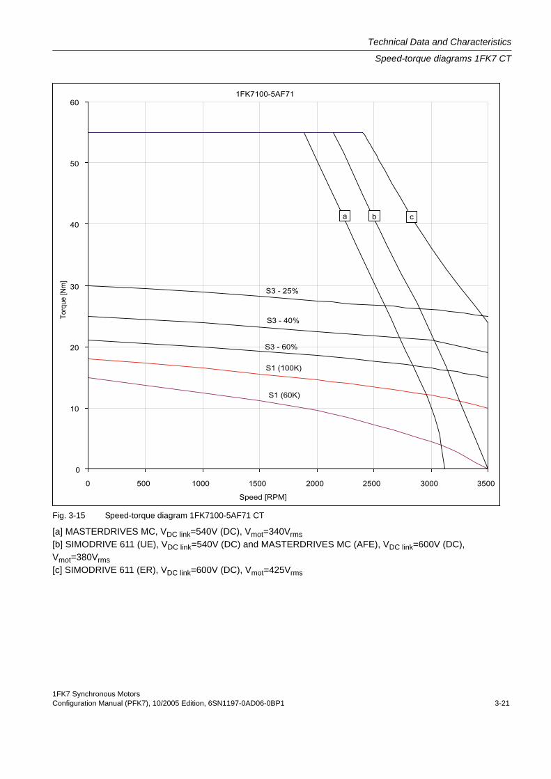
Fig. 3-15 Speed-torque diagram 1FK7100-5AF71 CT
[a] MASTERDRIVES MC, VDC link=540V (DC), Vmot=340Vrms[b] SIMODRIVE 611 (UE), VDC link=540V (DC) and MASTERDRIVES MC (AFE), VDC link=600V (DC), Vmot=380Vrms[c] SIMODRIVE 611 (ER), VDC link=600V (DC), Vmot=425Vrms

Technical Data and Characteristics
Speed-torque diagrams 1FK7 CT
1FK7 Synchronous Motors3-22 Configuration Manual (PFK7), 10/2005 Edition, 6SN1197-0AD06-0BP1
Table 3-11: 1FK7101 CT
Technical data Code Units –5AF71
Engineering data
Rated speed nN RPM 3000
Number of poles 2p 8
Rated torque (100K) MN(100K) Nm 15.5
Rated current IN A 11.8
Stall torque (60K) M0(60K) Nm 22.4
Stall torque (100K) M0(100K) Nm 27
Stall current (60K) I0 (60K) A 15.7
Stall current (100K) I0 (100K) A 19
Moment of inertia (with brake) Jmot 10–4 kgm2 92.3
Moment of inertia (without brake) Jmot 10–4 kgm2 79.9
Optimum operating point
Optimum speed nopt RPM 3000
Optimum power Popt kW 4.87
Limiting data
Max. permissible speed (mech.) nmax RPM 5000
Max. torque Mmax Nm 80
Peak current Imax A 63
Physical constants
Torque constant kT Nm/A 1.41
Voltage constant kE V/1000 RPM 90
Winding resistance at 20 °C Rph Ohm 0.15
Rotating field inductance LD mH 3.0
Electrical time constant Tel ms 20
Shaft torsional stiffness ct Nm/rad 165000
Mechanical time constant Tmech ms 1.80
Thermal time constant Tth min 60
Weight with brake m kg 24
Weight without brake m kg 21
1FK7 Synchronous MotorsConfiguration Manual (PFK7), 10/2005 Edition, 6SN1197-0AD06-0BP1 3-23
Technical Data and Characteristics
Speed-torque diagrams 1FK7 CT
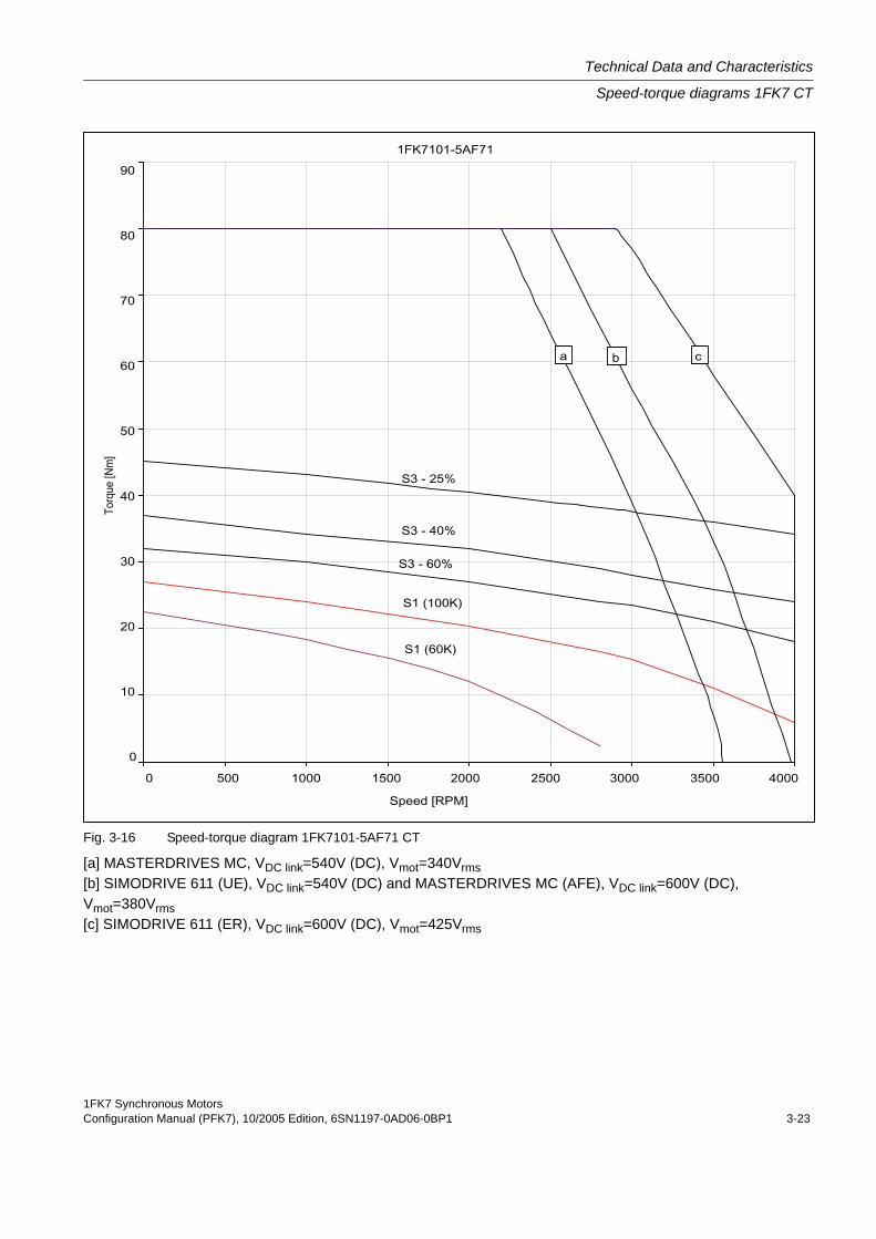
Fig. 3-16 Speed-torque diagram 1FK7101-5AF71 CT
[a] MASTERDRIVES MC, VDC link=540V (DC), Vmot=340Vrms[b] SIMODRIVE 611 (UE), VDC link=540V (DC) and MASTERDRIVES MC (AFE), VDC link=600V (DC), Vmot=380Vrms[c] SIMODRIVE 611 (ER), VDC link=600V (DC), Vmot=425Vrms

Technical Data and Characteristics
Speed-torque diagrams 1FK7 CT
1FK7 Synchronous Motors3-24 Configuration Manual (PFK7), 10/2005 Edition, 6SN1197-0AD06-0BP1
Table 3-12: 1FK7103 CT
Technical data Code Units –5AF71
Engineering data
Rated speed nN RPM 3000
Number of poles 2p 8
Rated torque (100K) MN(100K) Nm 14
Rated current IN A 12
Stall torque (60K) M0(60K) Nm 30
Stall torque (100K) M0(100K) Nm 36
Stall current (60K) I0 (60K) A 22.8
Stall current (100K) I0 (100K) A 27.5
Moment of inertia (with brake) Jmot 10–4 kgm2 118
Moment of inertia (without brake) Jmot 10–4 kgm2 105
Optimum operating point
Optimum speed nopt RPM 2500
Optimum power Popt kW 5.37
Limiting data
Max. permissible speed (mech.) nmax RPM 5000
Max. torque Mmax Nm 108
Peak current Imax A 84
Physical constants
Torque constant kT Nm/A 1.35
Voltage constant kE V/1000 RPM 86
Winding resistance at 20 °C Rph Ohm 0.09
Rotating field inductance LD mH 2.0
Electrical time constant Tel ms 22.2
Shaft torsional stiffness ct Nm/rad 149000
Mechanical time constant Tmech ms 1.55
Thermal time constant Tth min 65
Weight with brake m kg 32
Weight without brake m kg 29
1FK7 Synchronous MotorsConfiguration Manual (PFK7), 10/2005 Edition, 6SN1197-0AD06-0BP1 3-25
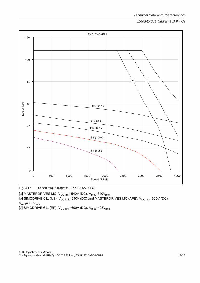
Technical Data and Characteristics
Speed-torque diagrams 1FK7 CT
Fig. 3-17 Speed-torque diagram 1FK7103-5AF71 CT
[a] MASTERDRIVES MC, VDC link=540V (DC), Vmot=340Vrms[b] SIMODRIVE 611 (UE), VDC link=540V (DC) and MASTERDRIVES MC (AFE), VDC link=600V (DC), Vmot=380Vrms[c] SIMODRIVE 611 (ER), VDC link=600V (DC), Vmot=425Vrms

Technical Data and Characteristics
Speed-torque diagrams 1FK7 CT
1FK7 Synchronous Motors3-26 Configuration Manual (PFK7), 10/2005 Edition, 6SN1197-0AD06-0BP1
Table 3-13: 1FK7105 CT
Technical data Code Units –5AC7 –5AF7Engineering data
Rated speed nN RPM 2000 3000Number of poles 2p 8 8
Rated torque (100K) MN(100K) Nm 37 26
Rated current IN A 16 18
Stall torque (60K) M0(60K) Nm 40 40
Stall torque (100K) M0(100K) Nm 48 48
Stall current (60K) I0 (60K) A 17 25
Stall current (100K) I0 (100K) A 20 31
Moment of inertia (with brake) Jmot 10–4 kgm2 169 169
Moment of inertia (without brake) Jmot 10–4 kgm2 156 156
Optimum operating point
Optimum speed nopt RPM 2000 3000
Optimum power Popt kW 7.75 8.17
Limiting data
Max. permissible speed (mech.) nmax RPM 5000 5000
Max. torque Mmax Nm 150 150
Peak current Imax A 72 109
Physical constants
Torque constant kT Nm/A 2.37 1.57
Voltage constant kE V/1000 RPM 151 100
Winding resistance at 20 °C Rph Ohm 0.17 0.074
Rotating field inductance LD mH 4.4 1.9
Electrical time constant Tel ms 26 26
Shaft torsional stiffness ct Nm/rad 125000 125000
Mechanical time constant Tmech ms 14.2 14.1
Thermal time constant Tth min 70 70
Weight with brake m kg 41.5 41.5
Weight without brake m kg 39.1 39.1
1FK7 Synchronous MotorsConfiguration Manual (PFK7), 10/2005 Edition, 6SN1197-0AD06-0BP1 3-27
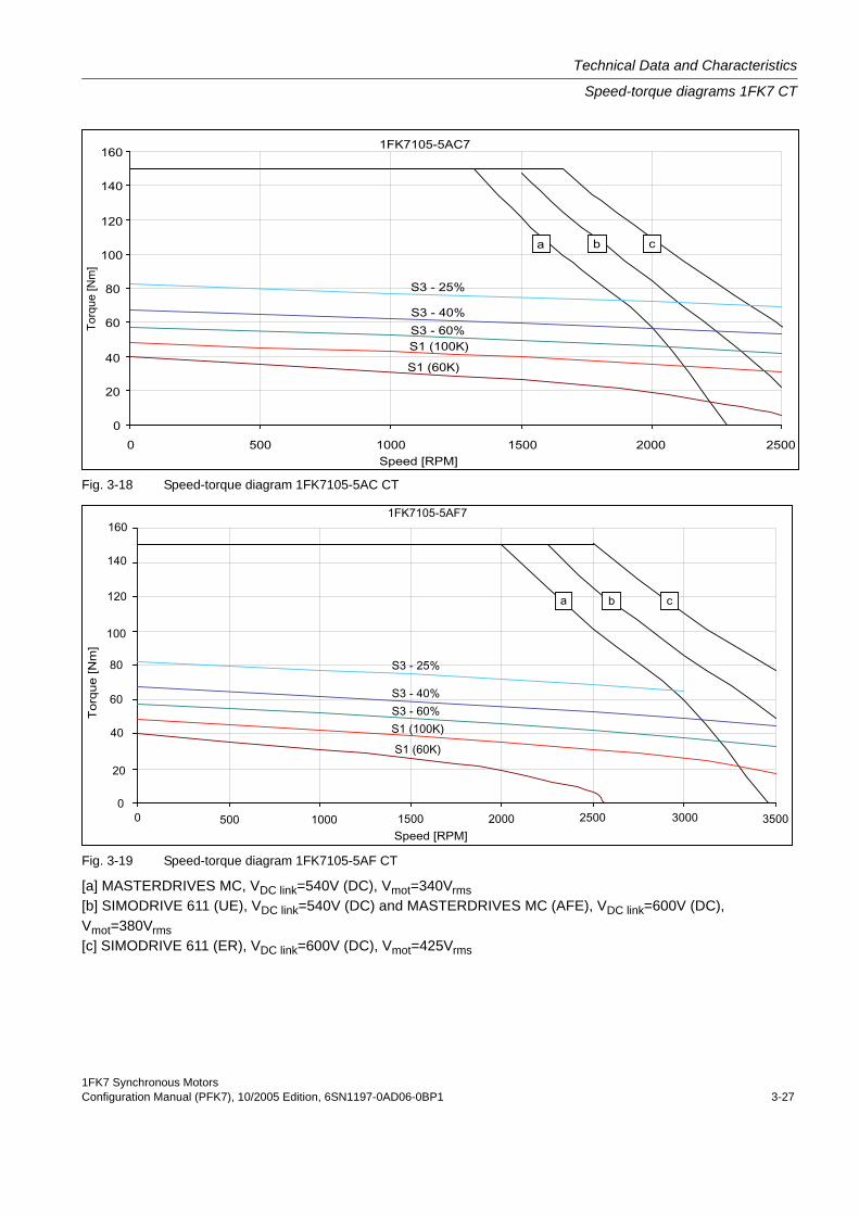
Technical Data and Characteristics
Speed-torque diagrams 1FK7 CT
Fig. 3-18 Speed-torque diagram 1FK7105-5AC CT
Fig. 3-19 Speed-torque diagram 1FK7105-5AF CT
[a] MASTERDRIVES MC, VDC link=540V (DC), Vmot=340Vrms[b] SIMODRIVE 611 (UE), VDC link=540V (DC) and MASTERDRIVES MC (AFE), VDC link=600V (DC), Vmot=380Vrms[c] SIMODRIVE 611 (ER), VDC link=600V (DC), Vmot=425Vrms
Technical Data and Characteristics
Speed-torque diagrams 1FK7 HD
1FK7 Synchronous Motors3-28 Configuration Manual (PFK7), 10/2005 Edition, 6SN1197-0AD06-0BP1
3.3 Speed-torque diagrams 1FK7 HD
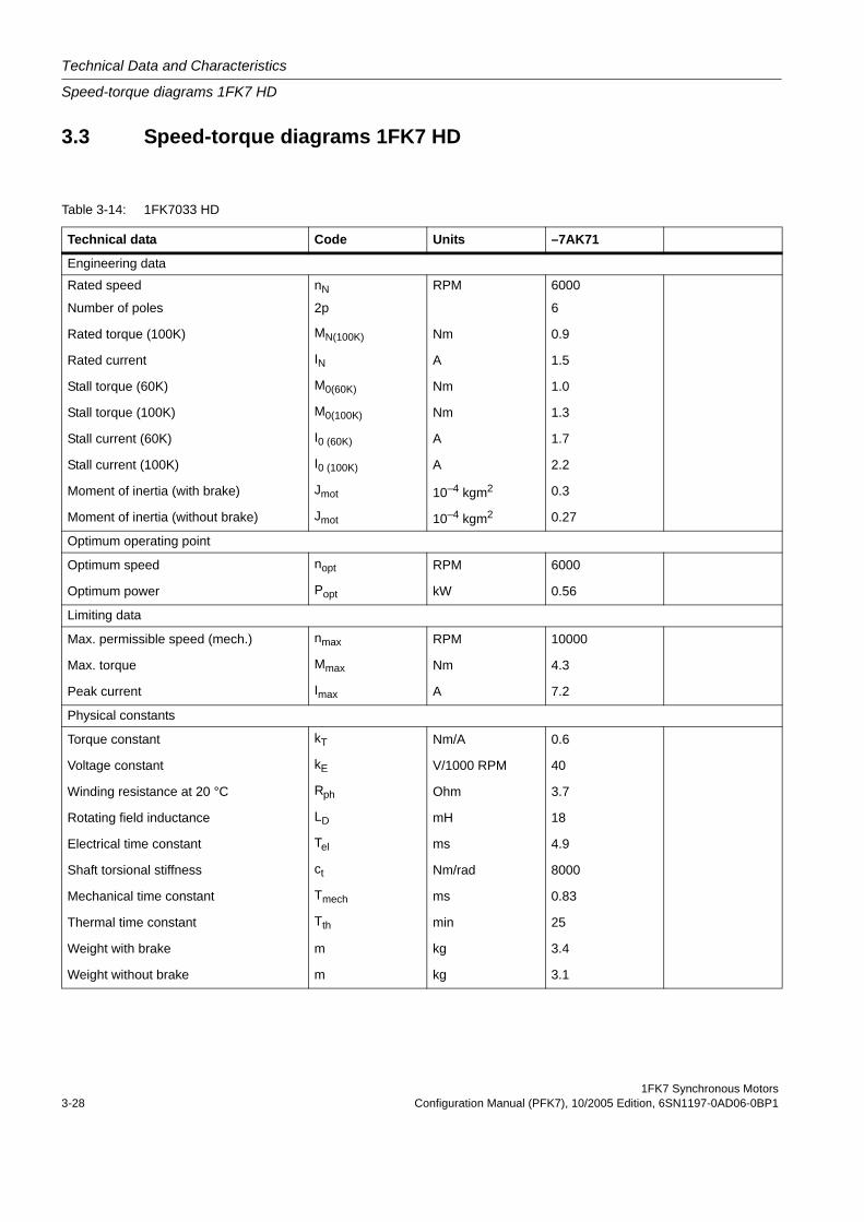
Table 3-14: 1FK7033 HD
Technical data Code Units –7AK71
Engineering data
Rated speed nN RPM 6000
Number of poles 2p 6
Rated torque (100K) MN(100K) Nm 0.9
Rated current IN A 1.5
Stall torque (60K) M0(60K) Nm 1.0
Stall torque (100K) M0(100K) Nm 1.3
Stall current (60K) I0 (60K) A 1.7
Stall current (100K) I0 (100K) A 2.2
Moment of inertia (with brake) Jmot 10–4 kgm2 0.3
Moment of inertia (without brake) Jmot 10–4 kgm2 0.27
Optimum operating point
Optimum speed nopt RPM 6000
Optimum power Popt kW 0.56
Limiting data
Max. permissible speed (mech.) nmax RPM 10000
Max. torque Mmax Nm 4.3
Peak current Imax A 7.2
Physical constants
Torque constant kT Nm/A 0.6
Voltage constant kE V/1000 RPM 40
Winding resistance at 20 °C Rph Ohm 3.7
Rotating field inductance LD mH 18
Electrical time constant Tel ms 4.9
Shaft torsional stiffness ct Nm/rad 8000
Mechanical time constant Tmech ms 0.83
Thermal time constant Tth min 25
Weight with brake m kg 3.4
Weight without brake m kg 3.1
1FK7 Synchronous MotorsConfiguration Manual (PFK7), 10/2005 Edition, 6SN1197-0AD06-0BP1 3-29
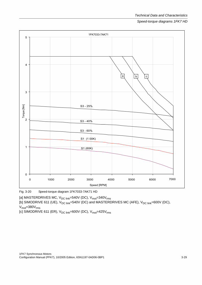
Technical Data and Characteristics
Speed-torque diagrams 1FK7 HD
Fig. 3-20 Speed-torque diagram 1FK7033-7AK71 HD
[a] MASTERDRIVES MC, VDC link=540V (DC), Vmot=340Vrms[b] SIMODRIVE 611 (UE), VDC link=540V (DC) and MASTERDRIVES MC (AFE), VDC link=600V (DC), Vmot=380Vrms[c] SIMODRIVE 611 (ER), VDC link=600V (DC), Vmot=425Vrms

Technical Data and Characteristics
Speed-torque diagrams 1FK7 HD
1FK7 Synchronous Motors3-30 Configuration Manual (PFK7), 10/2005 Edition, 6SN1197-0AD06-0BP1
Table 3-15: 1FK7043 HD
Technical data Code Units –7AH71 –7AK71Engineering data
Rated speed nN RPM 4500 6000Number of poles 2p 6 6
Rated torque (100K) MN(100K) Nm 2.6 2
Rated current IN A 4.0 4.4
Stall torque (60K) M0(60K) Nm 2.5 2.5
Stall torque (100K) M0(100K) Nm 3.1 3.1
Stall current (60K) I0 (60K) A 3.6 4.8
Stall current (100K) I0 (100K) A 4.5 6.4
Moment of inertia (with brake) Jmot 10–4 kgm2 1.14 1.14
Moment of inertia (without brake) Jmot 10–4 kgm2 1.01 1.01
Optimum operating point
Optimum speed nopt RPM 4500 6000
Optimum power Popt kW 1.23 1.26
Limiting data
Max. permissible speed (mech.) nmax RPM 8000 8000
Max. torque Mmax Nm 9.4 9.4
Peak current Imax A 14.8 20
Physical constants
Torque constant kT Nm/A 0.67 0.48
Voltage constant kE V/1000 RPM 44 32
Winding resistance at 20 °C Rph Ohm 1.2 0.65
Rotating field inductance LD mH 15 9
Electrical time constant Tel ms 12.5 13.8
Shaft torsional stiffness ct Nm/rad 11000 11000
Mechanical time constant Tmech ms 0.81 0.85
Thermal time constant Tth min 40 40
Weight with brake m kg 7.0 7.0
Weight without brake m kg 6.3 6.3
1FK7 Synchronous MotorsConfiguration Manual (PFK7), 10/2005 Edition, 6SN1197-0AD06-0BP1 3-31
Technical Data and Characteristics
Speed-torque diagrams 1FK7 HD
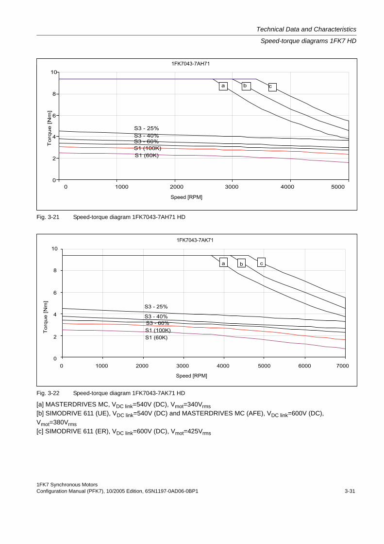
Fig. 3-21 Speed-torque diagram 1FK7043-7AH71 HD
Fig. 3-22 Speed-torque diagram 1FK7043-7AK71 HD
[a] MASTERDRIVES MC, VDC link=540V (DC), Vmot=340Vrms[b] SIMODRIVE 611 (UE), VDC link=540V (DC) and MASTERDRIVES MC (AFE), VDC link=600V (DC), Vmot=380Vrms[c] SIMODRIVE 611 (ER), VDC link=600V (DC), Vmot=425Vrms
Technical Data and Characteristics
Speed-torque diagrams 1FK7 HD
1FK7 Synchronous Motors3-32 Configuration Manual (PFK7), 10/2005 Edition, 6SN1197-0AD06-0BP1
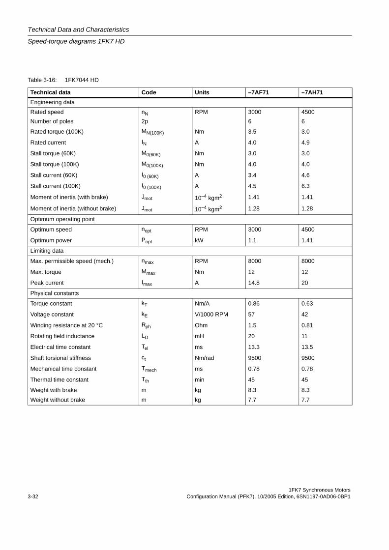
Table 3-16: 1FK7044 HD
Technical data Code Units –7AF71 –7AH71Engineering data
Rated speed nN RPM 3000 4500Number of poles 2p 6 6
Rated torque (100K) MN(100K) Nm 3.5 3.0
Rated current IN A 4.0 4.9
Stall torque (60K) M0(60K) Nm 3.0 3.0
Stall torque (100K) M0(100K) Nm 4.0 4.0
Stall current (60K) I0 (60K) A 3.4 4.6
Stall current (100K) I0 (100K) A 4.5 6.3
Moment of inertia (with brake) Jmot 10–4 kgm2 1.41 1.41
Moment of inertia (without brake) Jmot 10–4 kgm2 1.28 1.28
Optimum operating point
Optimum speed nopt RPM 3000 4500
Optimum power Popt kW 1.1 1.41
Limiting data
Max. permissible speed (mech.) nmax RPM 8000 8000
Max. torque Mmax Nm 12 12
Peak current Imax A 14.8 20
Physical constants
Torque constant kT Nm/A 0.86 0.63
Voltage constant kE V/1000 RPM 57 42
Winding resistance at 20 °C Rph Ohm 1.5 0.81
Rotating field inductance LD mH 20 11
Electrical time constant Tel ms 13.3 13.5
Shaft torsional stiffness ct Nm/rad 9500 9500
Mechanical time constant Tmech ms 0.78 0.78
Thermal time constant Tth min 45 45
Weight with brake m kg 8.3 8.3
Weight without brake m kg 7.7 7.7
1FK7 Synchronous MotorsConfiguration Manual (PFK7), 10/2005 Edition, 6SN1197-0AD06-0BP1 3-33
Technical Data and Characteristics
Speed-torque diagrams 1FK7 HD
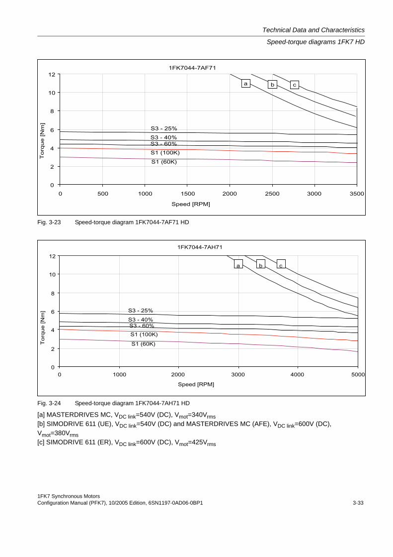
Fig. 3-23 Speed-torque diagram 1FK7044-7AF71 HD
Fig. 3-24 Speed-torque diagram 1FK7044-7AH71 HD
[a] MASTERDRIVES MC, VDC link=540V (DC), Vmot=340Vrms[b] SIMODRIVE 611 (UE), VDC link=540V (DC) and MASTERDRIVES MC (AFE), VDC link=600V (DC), Vmot=380Vrms[c] SIMODRIVE 611 (ER), VDC link=600V (DC), Vmot=425Vrms

Technical Data and Characteristics
Speed-torque diagrams 1FK7 HD
1FK7 Synchronous Motors3-34 Configuration Manual (PFK7), 10/2005 Edition, 6SN1197-0AD06-0BP1
Table 3-17: 1FK7061 HD
Technical data Code Units –7AF71 –7AH71Engineering data
Rated speed nN RPM 3000 4500Number of poles 2p 6 6
Rated torque (100K) MN(100K) Nm 5.4 4.3
Rated current IN A 5.3 5.9
Stall torque (60K) M0(60K) Nm 4.9 4.9
Stall torque (100K) M0(100K) Nm 6.4 6.4
Stall current (60K) I0 (60K) A 4.8 7.0
Stall current (100K) I0 (100K) A 6.1 8.0
Moment of inertia (with brake) Jmot 10–4 kgm2 3.74 3.74
Moment of inertia (without brake) Jmot 10–4 kgm2 3.4 3.4
Optimum operating point
Optimum speed nopt RPM 3000 4500
Optimum power Popt kW 1.7 2.03
Limiting data
Max. permissible speed (mech.) nmax RPM 6000 6000
Max. torque Mmax Nm 17.3 17.3
Peak current Imax A 17.5 25.3
Physical constants
Torque constant kT Nm/A 1.0 0.7
Voltage constant kE V/1000 RPM 66 46
Winding resistance at 20 °C Rph Ohm 0.74 0.36
Rotating field inductance LD mH 20 9.6
Electrical time constant Tel ms 27 27
Shaft torsional stiffness ct Nm/rad 37000 37000
Mechanical time constant Tmech ms 0.75 0.75
Thermal time constant Tth min 45 45
Weight with brake m kg 11.2 11.2
Weight without brake m kg 10 10
1FK7 Synchronous MotorsConfiguration Manual (PFK7), 10/2005 Edition, 6SN1197-0AD06-0BP1 3-35
Technical Data and Characteristics
Speed-torque diagrams 1FK7 HD
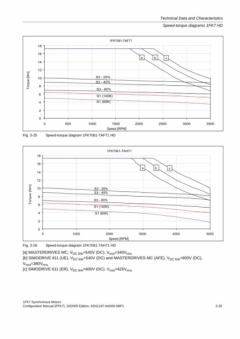
Fig. 3-25 Speed-torque diagram 1FK7061-7AF71 HD
Fig. 3-26 Speed-torque diagram 1FK7061-7AH71 HD
[a] MASTERDRIVES MC, VDC link=540V (DC), Vmot=340Vrms[b] SIMODRIVE 611 (UE), VDC link=540V (DC) and MASTERDRIVES MC (AFE), VDC link=600V (DC), Vmot=380Vrms[c] SIMODRIVE 611 (ER), VDC link=600V (DC), Vmot=425Vrms
Technical Data and Characteristics
Speed-torque diagrams 1FK7 HD
1FK7 Synchronous Motors3-36 Configuration Manual (PFK7), 10/2005 Edition, 6SN1197-0AD06-0BP1
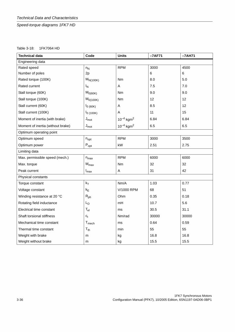
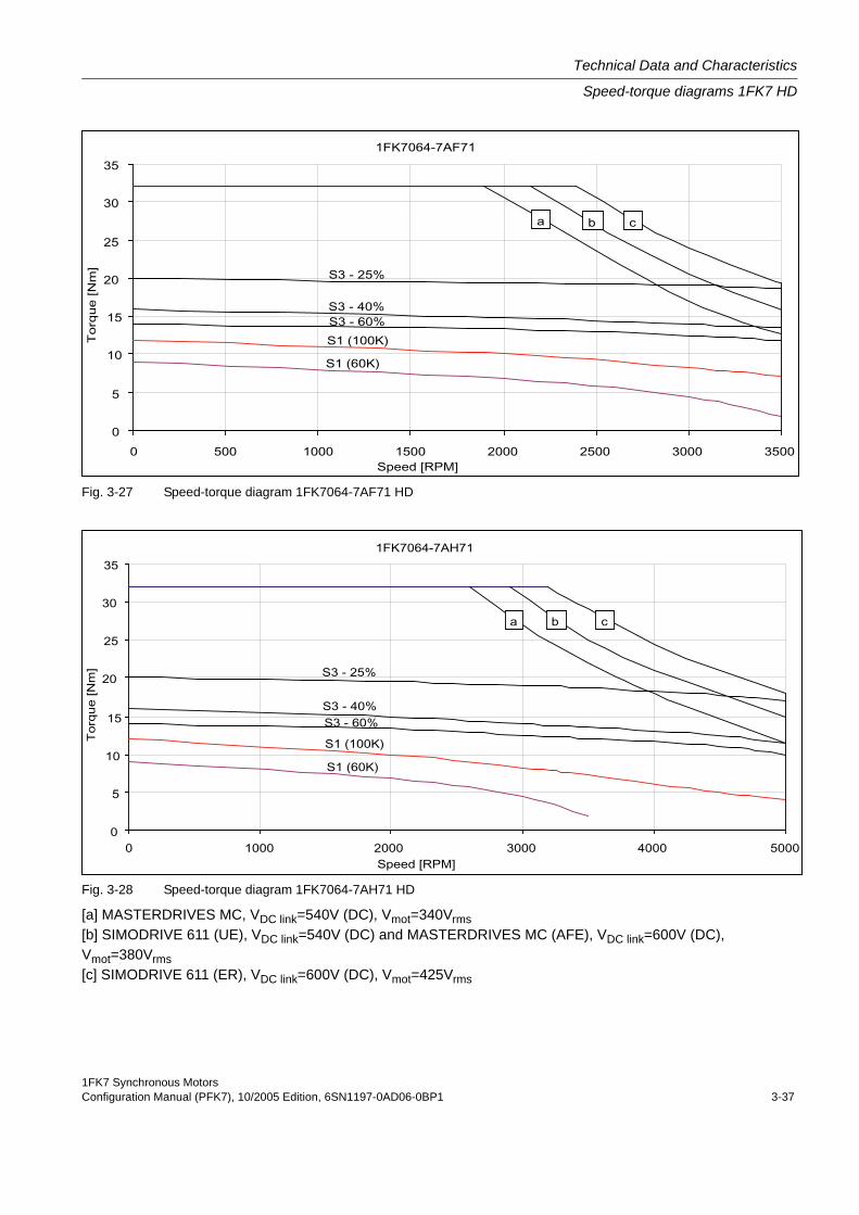
Table 3-18: 1FK7064 HD
Technical data Code Units –7AF71 –7AH71Engineering data
Rated speed nN RPM 3000 4500Number of poles 2p 6 6
Rated torque (100K) MN(100K) Nm 8.0 5.0
Rated current IN A 7.5 7.0
Stall torque (60K) M0(60K) Nm 9.0 9.0
Stall torque (100K) M0(100K) Nm 12 12
Stall current (60K) I0 (60K) A 8.5 12
Stall current (100K) I0 (100K) A 11 15
Moment of inertia (with brake) Jmot 10–4 kgm2 6.84 6.84
Moment of inertia (without brake) Jmot 10–4 kgm2 6.5 6.5
Optimum operating point
Optimum speed nopt RPM 3000 3500
Optimum power Popt kW 2.51 2.75
Limiting data
Max. permissible speed (mech.) nmax RPM 6000 6000
Max. torque Mmax Nm 32 32
Peak current Imax A 31 42
Physical constants
Torque constant kT Nm/A 1.03 0.77
Voltage constant kE V/1000 RPM 68 51
Winding resistance at 20 °C Rph Ohm 0.35 0.18
Rotating field inductance LD mH 10.7 5.6
Electrical time constant Tel ms 30.5 31.1
Shaft torsional stiffness ct Nm/rad 30000 30000
Mechanical time constant Tmech ms 0.64 0.59
Thermal time constant Tth min 55 55
Weight with brake m kg 16.8 16.8
Weight without brake m kg 15.5 15.5
1FK7 Synchronous MotorsConfiguration Manual (PFK7), 10/2005 Edition, 6SN1197-0AD06-0BP1 3-37
Technical Data and Characteristics
Speed-torque diagrams 1FK7 HD
Fig. 3-27 Speed-torque diagram 1FK7064-7AF71 HD
Fig. 3-28 Speed-torque diagram 1FK7064-7AH71 HD
[a] MASTERDRIVES MC, VDC link=540V (DC), Vmot=340Vrms[b] SIMODRIVE 611 (UE), VDC link=540V (DC) and MASTERDRIVES MC (AFE), VDC link=600V (DC), Vmot=380Vrms[c] SIMODRIVE 611 (ER), VDC link=600V (DC), Vmot=425Vrms
Technical Data and Characteristics
Speed-torque diagrams 1FK7 HD
1FK7 Synchronous Motors3-38 Configuration Manual (PFK7), 10/2005 Edition, 6SN1197-0AD06-0BP1
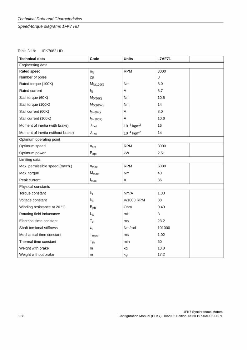
Table 3-19: 1FK7082 HD
Technical data Code Units –7AF71Engineering data
Rated speed nN RPM 3000Number of poles 2p 8
Rated torque (100K) MN(100K) Nm 8.0
Rated current IN A 6.7
Stall torque (60K) M0(60K) Nm 10.5
Stall torque (100K) M0(100K) Nm 14
Stall current (60K) I0 (60K) A 8.0
Stall current (100K) I0 (100K) A 10.6
Moment of inertia (with brake) Jmot 10–4 kgm2 16
Moment of inertia (without brake) Jmot 10–4 kgm2 14
Optimum operating point
Optimum speed nopt RPM 3000
Optimum power Popt kW 2.51
Limiting data
Max. permissible speed (mech.) nmax RPM 6000
Max. torque Mmax Nm 40
Peak current Imax A 36
Physical constants
Torque constant kT Nm/A 1.33
Voltage constant kE V/1000 RPM 88
Winding resistance at 20 °C Rph Ohm 0.43
Rotating field inductance LD mH 8
Electrical time constant Tel ms 23.2
Shaft torsional stiffness ct Nm/rad 101000
Mechanical time constant Tmech ms 1.02
Thermal time constant Tth min 60
Weight with brake m kg 18.8
Weight without brake m kg 17.2
1FK7 Synchronous MotorsConfiguration Manual (PFK7), 10/2005 Edition, 6SN1197-0AD06-0BP1 3-39
Technical Data and Characteristics
Speed-torque diagrams 1FK7 HD
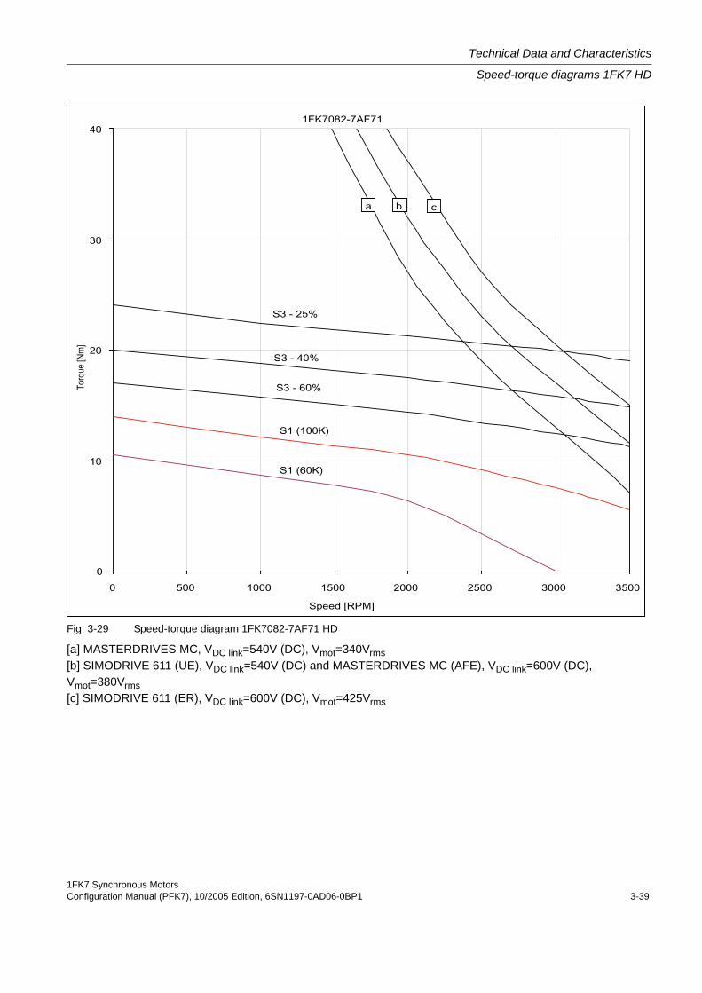
Fig. 3-29 Speed-torque diagram 1FK7082-7AF71 HD
[a] MASTERDRIVES MC, VDC link=540V (DC), Vmot=340Vrms[b] SIMODRIVE 611 (UE), VDC link=540V (DC) and MASTERDRIVES MC (AFE), VDC link=600V (DC), Vmot=380Vrms[c] SIMODRIVE 611 (ER), VDC link=600V (DC), Vmot=425Vrms

Technical Data and Characteristics
Speed-torque diagrams 1FK7 HD
1FK7 Synchronous Motors3-40 Configuration Manual (PFK7), 10/2005 Edition, 6SN1197-0AD06-0BP1
Table 3-20: 1FK7085 HD
Technical data Code Units –7AF71Engineering data
Rated speed nN RPM 3000Number of poles 2p 8
Rated torque (100K) MN(100K) Nm 6.5
Rated current IN A 7.0
Stall torque (60K) M0(60K) Nm 17
Stall torque (100K) M0(100K) Nm 22
Stall current (60K) I0 (60K) A 16.5
Stall current (100K) I0 (100K) A 22.5
Moment of inertia (with brake) Jmot 10–4 kgm2 25
Moment of inertia (without brake) Jmot 10–4 kgm2 23
Optimum operating point
Optimum speed nopt RPM 2500
Optimum power Popt kW 3.14
Limiting data
Max. permissible speed (mech.) nmax RPM 6000
Max. torque Mmax Nm 35
Peak current Imax A 80
Physical constants
Torque constant kT Nm/A 0.96
Voltage constant kE V/1000 RPM 63
Winding resistance at 20 °C Rph Ohm 0.12
Rotating field inductance LD mH 3.3
Electrical time constant Tel ms 27.5
Shaft torsional stiffness ct Nm/rad 83000
Mechanical time constant Tmech ms 0.9
Thermal time constant Tth min 65
Weight with brake m kg 25.7
Weight without brake m kg 23.5
1FK7 Synchronous MotorsConfiguration Manual (PFK7), 10/2005 Edition, 6SN1197-0AD06-0BP1 3-41
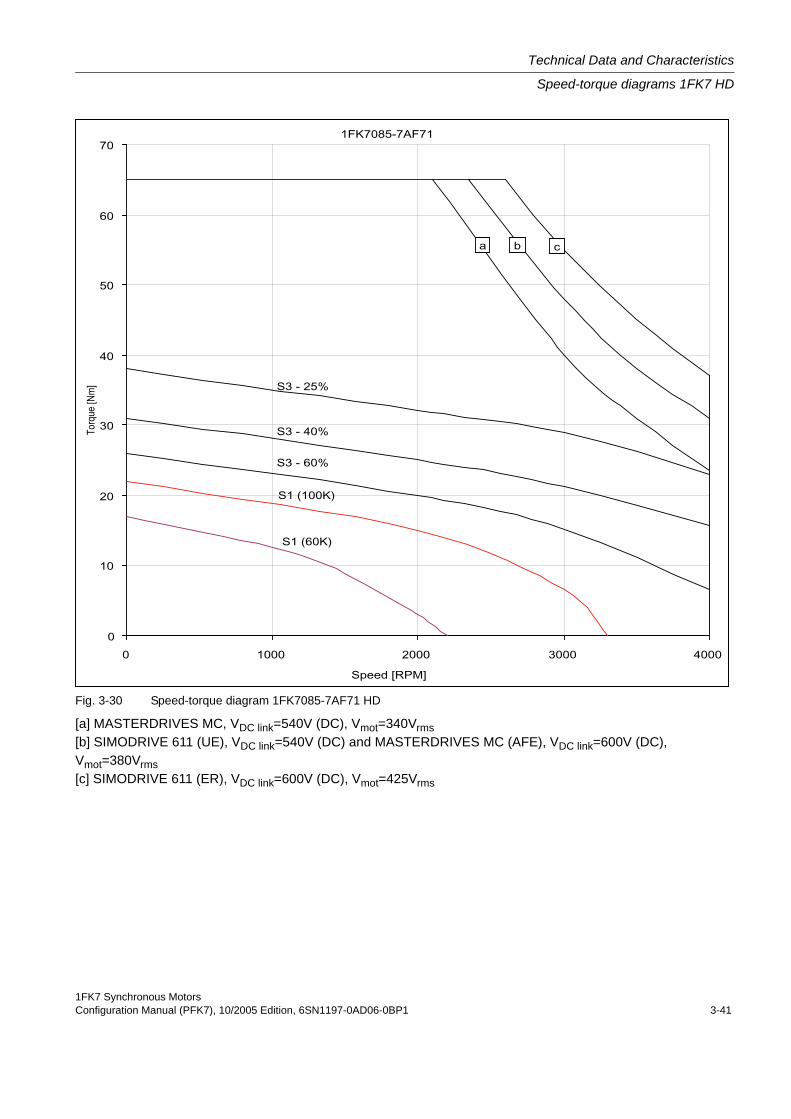
Technical Data and Characteristics
Speed-torque diagrams 1FK7 HD
Fig. 3-30 Speed-torque diagram 1FK7085-7AF71 HD
[a] MASTERDRIVES MC, VDC link=540V (DC), Vmot=340Vrms[b] SIMODRIVE 611 (UE), VDC link=540V (DC) and MASTERDRIVES MC (AFE), VDC link=600V (DC), Vmot=380Vrms[c] SIMODRIVE 611 (ER), VDC link=600V (DC), Vmot=425Vrms

Technical Data and Characteristics
Speed-torque diagrams 1FK7 HD
1FK7 Synchronous Motors3-42 Configuration Manual (PFK7), 10/2005 Edition, 6SN1197-0AD06-0BP1
Table 3-21: 1FK7086 HD
Technical data Code Units –7AF71
Engineering data
Rated speed nN RPM 3000
Number of poles 2p 8
Rated torque (100K) MN(100K) Nm 6.5
Rated current IN A 5.5
Stall torque (60K) M0(60K) Nm 23.5
Stall torque (100K) M0(100K) Nm 28
Stall current (60K) I0 (60K) A 17
Stall current (100K) I0 (100K) A 21
Moment of inertia (with brake) Jmot 10–4 kgm2 25
Moment of inertia (without brake) Jmot 10–4 kgm2 23
Optimum operating point
Optimum speed nopt RPM 2000
Optimum power Popt kW 3.77
Limiting data
Max. permissible speed (mech.) nmax RPM 6000
Max. torque Mmax Nm 105
Peak current Imax A 112
Physical constants
Torque constant kT Nm/A 1.33
Voltage constant kE V/1000 RPM 85
Winding resistance at 20 °C Rph Ohm 0.12
Rotating field inductance LD mH 3
Electrical time constant Tel ms 25
Shaft torsional stiffness ct Nm/rad 83000
Mechanical time constant Tmech ms 0.47
Thermal time constant Tth min 65
Weight with brake m kg 25.7
Weight without brake m kg 23.5
1FK7 Synchronous MotorsConfiguration Manual (PFK7), 10/2005 Edition, 6SN1197-0AD06-0BP1 3-43
Technical Data and Characteristics
Speed-torque diagrams 1FK7 HD
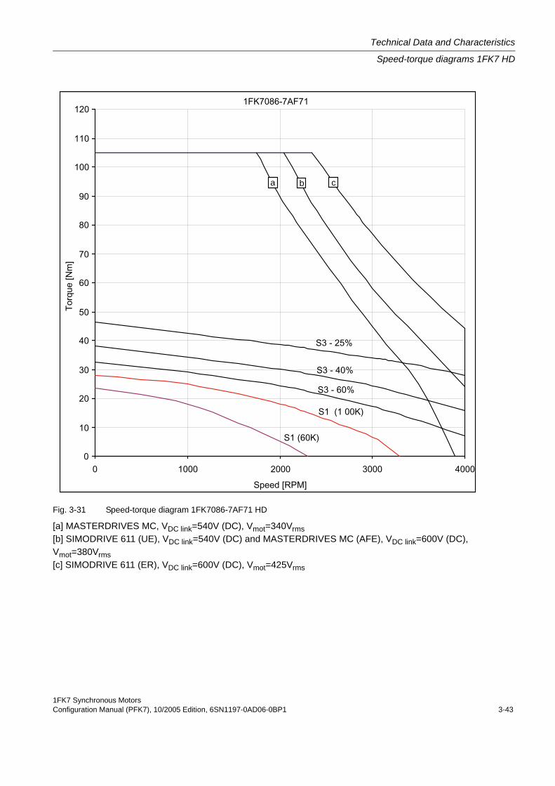
Fig. 3-31 Speed-torque diagram 1FK7086-7AF71 HD
[a] MASTERDRIVES MC, VDC link=540V (DC), Vmot=340Vrms[b] SIMODRIVE 611 (UE), VDC link=540V (DC) and MASTERDRIVES MC (AFE), VDC link=600V (DC), Vmot=380Vrms[c] SIMODRIVE 611 (ER), VDC link=600V (DC), Vmot=425Vrms
c a b
Technical Data and Characteristics
Cantilever force diagrams
1FK7 Synchronous Motors3-44 Configuration Manual (PFK7), 10/2005 Edition, 6SN1197-0AD06-0BP1
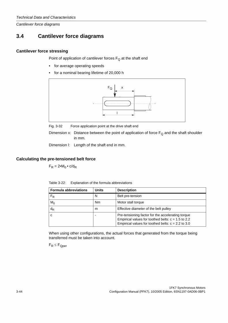
3.4 Cantilever force diagrams
Cantilever force stressingPoint of application of cantilever forces FQ at the shaft end
• for average operating speeds
• for a nominal bearing lifetime of 20,000 h
Fig. 3-32 Force application point at the drive shaft end
Dimension x: Distance between the point of application of force FQ and the shaft shoulder in mm.
Dimension l: Length of the shaft end in mm.
Calculating the pre-tensioned belt forceFR = 2•M0 • c/dR
When using other configurations, the actual forces that generated from the torque being transferred must be taken into account.
FR ≤ FQper
Table 3-22: Explanation of the formula abbreviations
Formula abbreviations Units DescriptionFR N Belt pre-tension
M0 Nm Motor stall torque
dR m Effective diameter of the belt pulley
c - Pre-tensioning factor for the accelerating torqueEmpirical values for toothed belts: c = 1.5 to 2.2Empirical values for toothed belts: c = 2.2 to 3.0
1FK7 Synchronous MotorsConfiguration Manual (PFK7), 10/2005 Edition, 6SN1197-0AD06-0BP1 3-45
Technical Data and Characteristics
Cantilever force diagrams
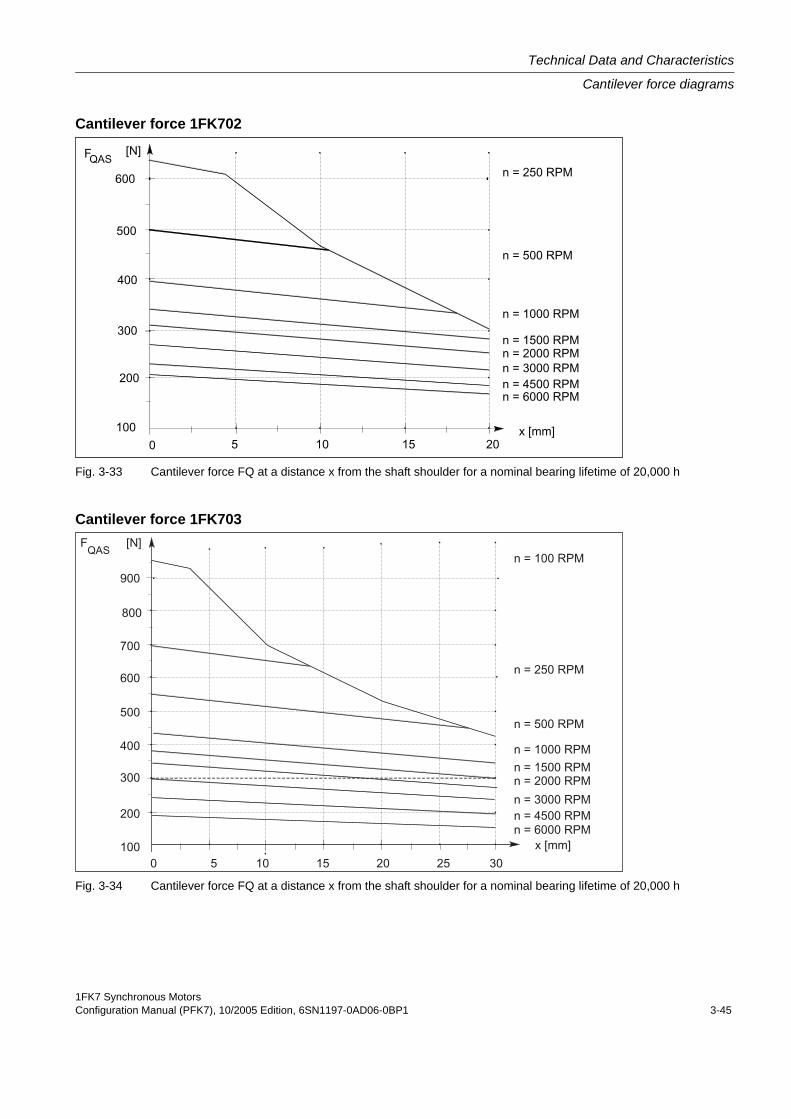
Cantilever force 1FK702
Fig. 3-33 Cantilever force FQ at a distance x from the shaft shoulder for a nominal bearing lifetime of 20,000 h
Cantilever force 1FK703
Fig. 3-34 Cantilever force FQ at a distance x from the shaft shoulder for a nominal bearing lifetime of 20,000 h
Technical Data and Characteristics
Cantilever force diagrams
1FK7 Synchronous Motors3-46 Configuration Manual (PFK7), 10/2005 Edition, 6SN1197-0AD06-0BP1
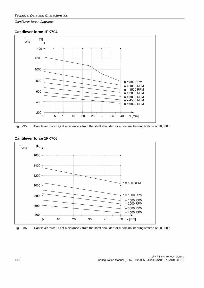
Cantilever force 1FK704
Fig. 3-35 Cantilever force FQ at a distance x from the shaft shoulder for a nominal bearing lifetime of 20,000 h
Cantilever force 1FK706
Fig. 3-36 Cantilever force FQ at a distance x from the shaft shoulder for a nominal bearing lifetime of 20,000 h
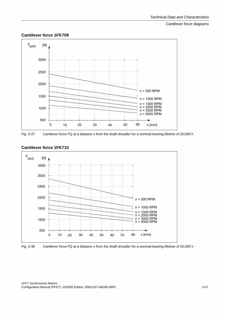
1FK7 Synchronous MotorsConfiguration Manual (PFK7), 10/2005 Edition, 6SN1197-0AD06-0BP1 3-47
Technical Data and Characteristics
Cantilever force diagrams
Cantilever force 1FK708
Fig. 3-37 Cantilever force FQ at a distance x from the shaft shoulder for a nominal bearing lifetime of 20,000 h
Cantilever force 1FK710
Fig. 3-38 Cantilever force FQ at a distance x from the shaft shoulder for a nominal bearing lifetime of 20,000 h
Technical Data and Characteristics
Axial forces
1FK7 Synchronous Motors3-48 Configuration Manual (PFK7), 10/2005 Edition, 6SN1197-0AD06-0BP1
3.5 Axial forces
Axial force stressing
When using, for example, helical toothed wheels as drive element, in addition to the radial force, there is also an axial force on the motor bearings. For axial forces, the spring-loading of the bearings can be overcome so that the rotor moves corresponding to the axial bearing play present (up to 0.2 mm).
The permissible axial force can be approximately calculated using the following formula:
FA = 0.35 • FQ
WarningMotors with integrated holding brake cannot be subject to axial forces!
1FK7 Synchronous MotorsConfiguration Manual (PFK7), 10/2005 Edition, 6SN1197-0AD06-0BP1 4-1
Motor Components (Options) 44.1 Thermal motor protection
A temperature-dependent resistor is integrated as temperature sensor to monitor the motor temperature.
The resistance of the KTY 84 thermistor changes proportionally to the winding temperature change.
The temperature signal is sensed and evaluated in the drive converter whose closed-loop control takes into account the temperature characteristic of the motor resistances.
When a fault occurs, an appropriate message is output at the drive converter. When the motor temperature increases, a message "Alarm motor overtemperature" is output; this must be externally evaluated. If this signal is not observed, the drive converter shuts down with the appropriate fault message when the motor limiting temperature or the shutdown temperature is exceeded.
The temperature sensor is designed so that the DIN/EN requirement for "protective separa-tion" is fulfilled.
Table 4-1: Features and technical data
Type KTY 84
Resistance when cold (20°C) approx. 580 Ohm
Resistance when hot (100°C) approx. 1000 Ohm
Connection via signal cable
WarningIf the user carries-out an additional high-voltage test, then the ends of the temperature sensor cables must be short-circuited before the test is carried-out!
If the test voltage is connected to a temperature sensor terminal, then it will be destroyed.
The polarity must be carefully observed.
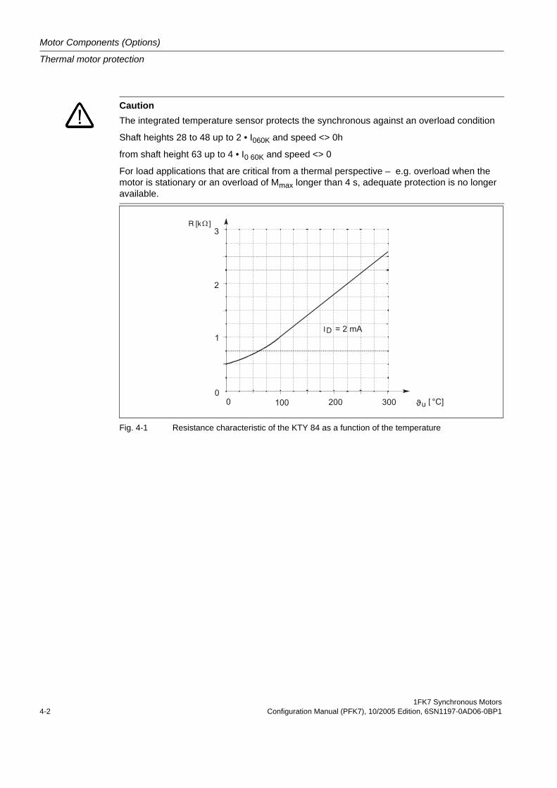
Motor Components (Options)
Thermal motor protection
1FK7 Synchronous Motors4-2 Configuration Manual (PFK7), 10/2005 Edition, 6SN1197-0AD06-0BP1
Fig. 4-1 Resistance characteristic of the KTY 84 as a function of the temperature
CautionThe integrated temperature sensor protects the synchronous against an overload condition
Shaft heights 28 to 48 up to 2 • I060K and speed <> 0h
from shaft height 63 up to 4 • I0 60K and speed <> 0
For load applications that are critical from a thermal perspective – e.g. overload when the motor is stationary or an overload of Mmax longer than 4 s, adequate protection is no longer available.
[
I
R [kΩ
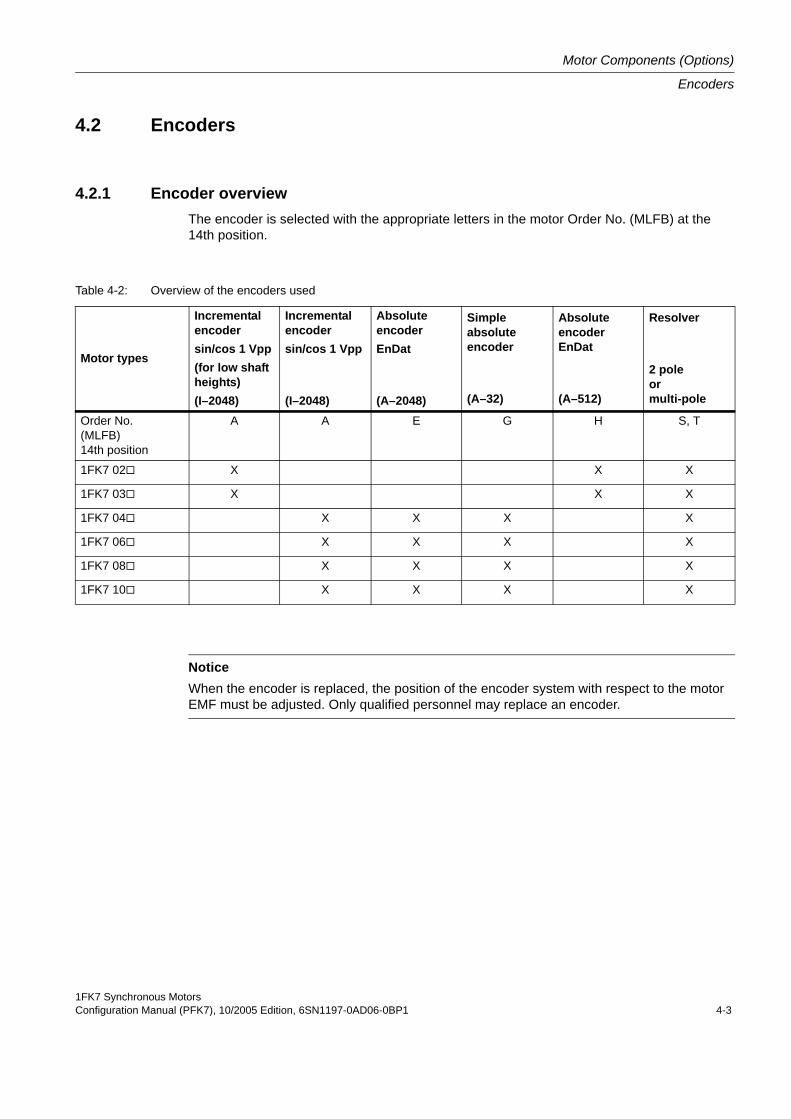
1FK7 Synchronous MotorsConfiguration Manual (PFK7), 10/2005 Edition, 6SN1197-0AD06-0BP1 4-3
Motor Components (Options)
Encoders
4.2 Encoders
4.2.1 Encoder overviewThe encoder is selected with the appropriate letters in the motor Order No. (MLFB) at the 14th position.
Table 4-2: Overview of the encoders used
Motor types
Incremental encodersin/cos 1 Vpp(for low shaft heights)(I–2048)
Incremental encodersin/cos 1 Vpp
(I–2048)
Absolute encoderEnDat
(A–2048)
Simple absolute encoder
(A–32)
AbsoluteencoderEnDat
(A–512)
Resolver
2 pole or multi-pole
Order No. (MLFB) 14th position
A A E G H S, T
1FK7 02 X X X
1FK7 03 X X X
1FK7 04 X X X X
1FK7 06 X X X X
1FK7 08 X X X X
1FK7 10 X X X X
NoticeWhen the encoder is replaced, the position of the encoder system with respect to the motor EMF must be adjusted. Only qualified personnel may replace an encoder.
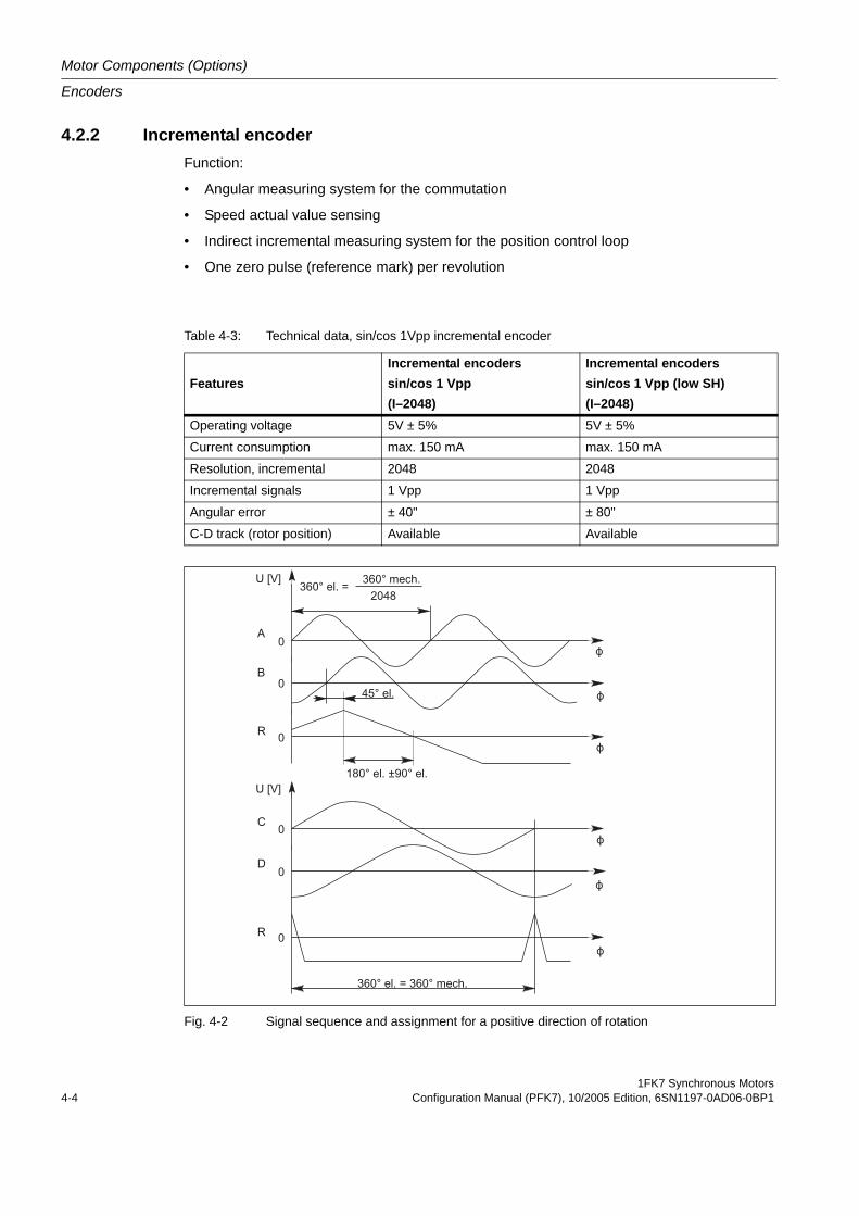
Motor Components (Options)
Encoders
1FK7 Synchronous Motors4-4 Configuration Manual (PFK7), 10/2005 Edition, 6SN1197-0AD06-0BP1
4.2.2 Incremental encoder Function:
• Angular measuring system for the commutation
• Speed actual value sensing
• Indirect incremental measuring system for the position control loop
• One zero pulse (reference mark) per revolution
Fig. 4-2 Signal sequence and assignment for a positive direction of rotation
Table 4-3: Technical data, sin/cos 1Vpp incremental encoder
FeaturesIncremental encoderssin/cos 1 Vpp (I–2048)
Incremental encoderssin/cos 1 Vpp (low SH)(I–2048)
Operating voltage 5V ± 5% 5V ± 5%
Current consumption max. 150 mA max. 150 mA
Resolution, incremental 2048 2048
Incremental signals 1 Vpp 1 Vpp
Angular error ± 40" ± 80"
C-D track (rotor position) Available Available
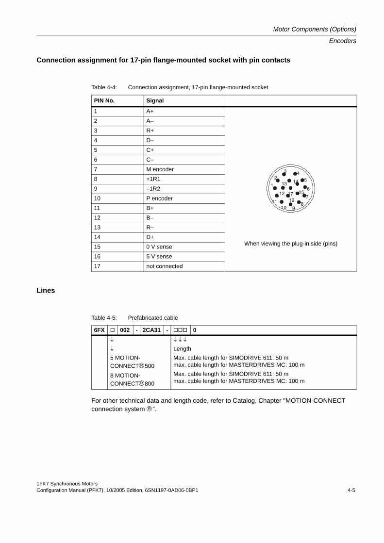
1FK7 Synchronous MotorsConfiguration Manual (PFK7), 10/2005 Edition, 6SN1197-0AD06-0BP1 4-5
Motor Components (Options)
Encoders
Connection assignment for 17-pin flange-mounted socket with pin contacts
Lines
For other technical data and length code, refer to Catalog, Chapter "MOTION-CONNECT connection system ®".
Table 4-4: Connection assignment, 17-pin flange-mounted socket
PIN No. Signal
1 A+
When viewing the plug-in side (pins)
2 A–
3 R+
4 D–
5 C+
6 C–
7 M encoder
8 +1R1
9 –1R2
10 P encoder
11 B+
12 B–
13 R–
14 D+
15 0 V sense
16 5 V sense
17 not connected
45
6
7
8910
11
1
23
14
17 15
1612
13
Table 4-5: Prefabricated cable
6FX 002 - 2CA31 - 0↓
↓
5 MOTION-CONNECT®5008 MOTION-CONNECT®800
↓ ↓ ↓
LengthMax. cable length for SIMODRIVE 611: 50 mmax. cable length for MASTERDRIVES MC: 100 mMax. cable length for SIMODRIVE 611: 50 mmax. cable length for MASTERDRIVES MC: 100 m
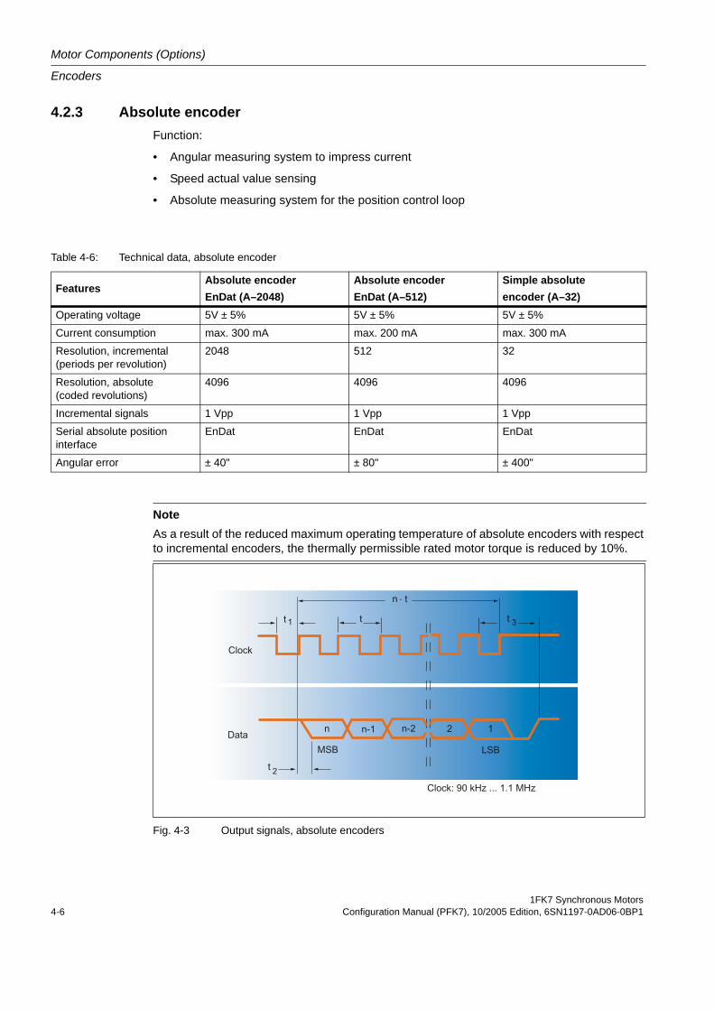
Motor Components (Options)
Encoders
1FK7 Synchronous Motors4-6 Configuration Manual (PFK7), 10/2005 Edition, 6SN1197-0AD06-0BP1
4.2.3 Absolute encoderFunction:
• Angular measuring system to impress current
• Speed actual value sensing
• Absolute measuring system for the position control loop
Fig. 4-3 Output signals, absolute encoders
Table 4-6: Technical data, absolute encoder
FeaturesAbsolute encoderEnDat (A–2048)
Absolute encoderEnDat (A–512)
Simple absoluteencoder (A–32)
Operating voltage 5V ± 5% 5V ± 5% 5V ± 5%
Current consumption max. 300 mA max. 200 mA max. 300 mA
Resolution, incremental (periods per revolution)
2048 512 32
Resolution, absolute (coded revolutions)
4096 4096 4096
Incremental signals 1 Vpp 1 Vpp 1 Vpp
Serial absolute position interface
EnDat EnDat EnDat
Angular error ± 40" ± 80" ± 400"
NoteAs a result of the reduced maximum operating temperature of absolute encoders with respect to incremental encoders, the thermally permissible rated motor torque is reduced by 10%.
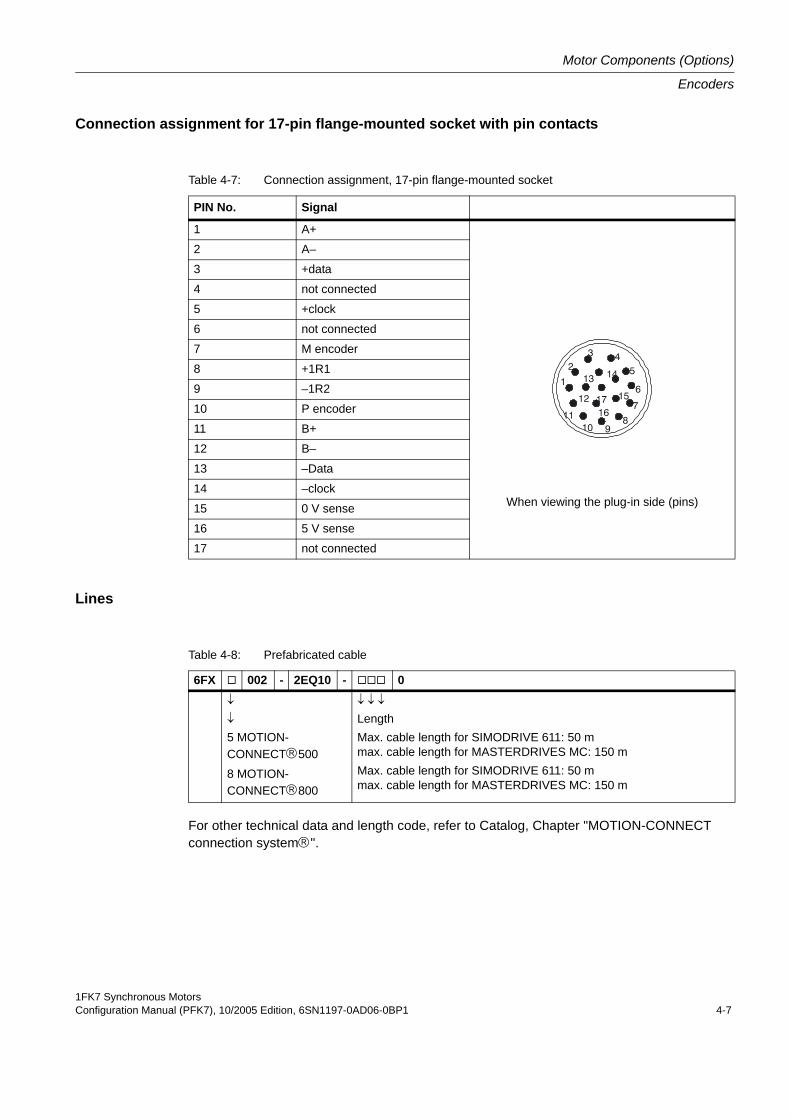
1FK7 Synchronous MotorsConfiguration Manual (PFK7), 10/2005 Edition, 6SN1197-0AD06-0BP1 4-7
Motor Components (Options)
Encoders
Connection assignment for 17-pin flange-mounted socket with pin contacts
Lines
For other technical data and length code, refer to Catalog, Chapter "MOTION-CONNECT connection system®".
Table 4-7: Connection assignment, 17-pin flange-mounted socket
PIN No. Signal
1 A+
When viewing the plug-in side (pins)
2 A–
3 +data
4 not connected
5 +clock
6 not connected
7 M encoder
8 +1R1
9 –1R2
10 P encoder
11 B+
12 B–
13 –Data
14 –clock
15 0 V sense
16 5 V sense
17 not connected
45
6
7
8910
11
1
23
14
17 15
1612
13
Table 4-8: Prefabricated cable
6FX 002 - 2EQ10 - 0↓
↓
5 MOTION-CONNECT®5008 MOTION-CONNECT®800
↓ ↓ ↓
LengthMax. cable length for SIMODRIVE 611: 50 mmax. cable length for MASTERDRIVES MC: 150 mMax. cable length for SIMODRIVE 611: 50 mmax. cable length for MASTERDRIVES MC: 150 m
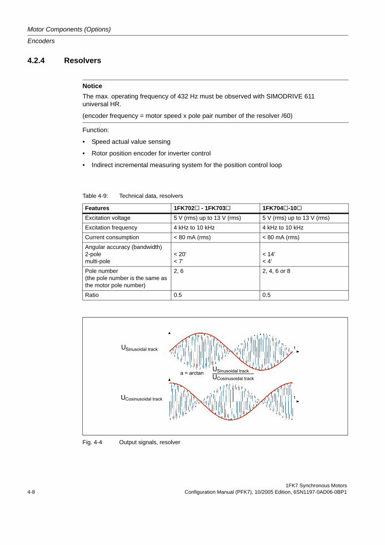
Motor Components (Options)
Encoders
1FK7 Synchronous Motors4-8 Configuration Manual (PFK7), 10/2005 Edition, 6SN1197-0AD06-0BP1
4.2.4 Resolvers
Function:
• Speed actual value sensing
• Rotor position encoder for inverter control
• Indirect incremental measuring system for the position control loop
Fig. 4-4 Output signals, resolver
NoticeThe max. operating frequency of 432 Hz must be observed with SIMODRIVE 611 universal HR.
(encoder frequency = motor speed x pole pair number of the resolver /60)
Table 4-9: Technical data, resolvers
Features 1FK702 - 1FK703 1FK704 -10Excitation voltage 5 V (rms) up to 13 V (rms) 5 V (rms) up to 13 V (rms)
Excitation frequency 4 kHz to 10 kHz 4 kHz to 10 kHz
Current consumption < 80 mA (rms) < 80 mA (rms)
Angular accuracy (bandwidth)2-polemulti-pole
< 20' < 7'
< 14' < 4'
Pole number(the pole number is the same as the motor pole number)
2, 6 2, 4, 6 or 8
Ratio 0.5 0.5
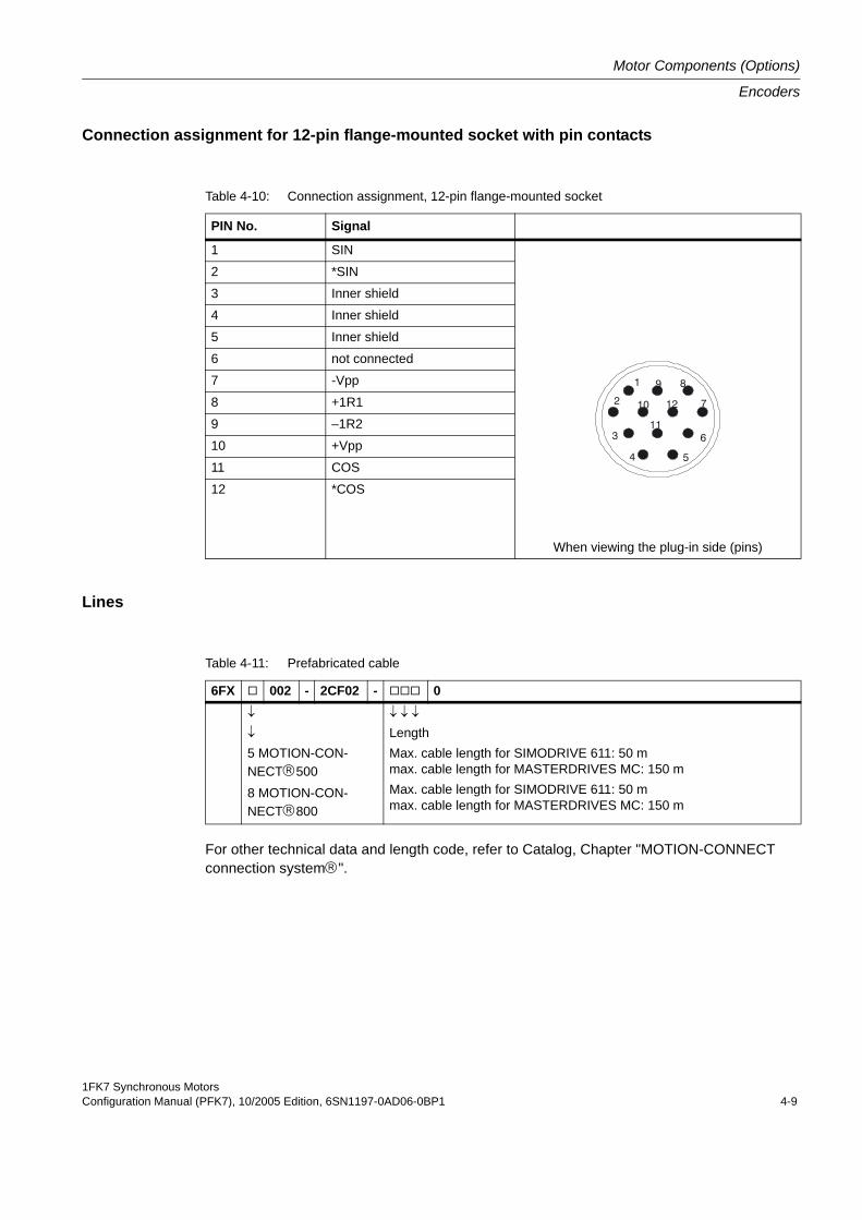
1FK7 Synchronous MotorsConfiguration Manual (PFK7), 10/2005 Edition, 6SN1197-0AD06-0BP1 4-9
Motor Components (Options)
Encoders
Connection assignment for 12-pin flange-mounted socket with pin contacts
Lines
For other technical data and length code, refer to Catalog, Chapter "MOTION-CONNECT connection system®".
Table 4-10: Connection assignment, 12-pin flange-mounted socket
PIN No. Signal
1 SIN
When viewing the plug-in side (pins)
2 *SIN
3 Inner shield
4 Inner shield
5 Inner shield
6 not connected
7 -Vpp
8 +1R1
9 –1R2
10 +Vpp
11 COS
12 *COS
2
1
10 12
1163
9 8
7
4 5
Table 4-11: Prefabricated cable
6FX 002 - 2CF02 - 0↓
↓
5 MOTION-CON-NECT®5008 MOTION-CON-NECT®800
↓ ↓ ↓
LengthMax. cable length for SIMODRIVE 611: 50 mmax. cable length for MASTERDRIVES MC: 150 mMax. cable length for SIMODRIVE 611: 50 mmax. cable length for MASTERDRIVES MC: 150 m
Motor Components (Options)
Holding brake
1FK7 Synchronous Motors4-10 Configuration Manual (PFK7), 10/2005 Edition, 6SN1197-0AD06-0BP1
4.3 Holding brake
4.3.1 Features • The integrated or mounted holding brake is used to clamp the motor shaft when the motor
is at a standstill. The holding brake is not a working brake that is used to brake a motor that is still rotating.
• Motors with or without holding brake cannot be subsequently retrofitted! Motors with holding brake are longer by the mounted space required (refer to the dimen-sion drawing).
• Restricted Emergency Stop operation is permissible. Up to 2000 braking operations can be executed with 300% rotor moment of inertia as external moment of inertia from a speed of 3000 RPM without the brake being subject to an inadmissible amount of wear. The specific highest switching work for each emergency braking operation may not be exceeded.
• The rated voltage of the holding brake is 24 V DC.
CautionThe rated voltage is 24 V DC +/- 10%. Voltages outside this tolerance bandwidth can result in faults.
Inadmissible wear means that the braking function can no longer be guaranteed! It is not permissible to exceed the above specified Emergency Stop conditions or to repeatedly briefly accelerate the motor against a holding brake that is still closed. This means that the switching times of the brakes and relays must be taken into account in the drive control and enable functions.
1FK7 Synchronous MotorsConfiguration Manual (PFK7), 10/2005 Edition, 6SN1197-0AD06-0BP1 4-11
Motor Components (Options)
Holding brake
4.3.2 Brake typesBrakes with different principles of operation are used:
• Permanent-magnet brake
• Spring-operated brake
Both of the brake types operate according to the closed-circuit principle.
Mode of operation of a permanent-magnet brakeThe magnetic field of the permanent magnets results in a pulling force on the brake armature disk. This means that in the no-current condition, the brake is closed and the motor shaft is held. When 24 V DC rated voltage is connected to the brake, the solenoid – through which current flows – establishes an opposing field. This neutralizes the force of the permanent magnets.Permanent magnet brakes have a proportionally stiff connection to the motor rotor. This is the reason that this brake is almost without any play.
Mode of operation of a spring-operated brakeFor a spring-operated brake, instead of the magnetic field of a permanent magnet, the force of a spring is used.In order for a spring-operated brake to operate, the brake armature disk must be able to axially move. Therefore, torsional backlash cannot be avoided. When the brake is closed, the motor shaft can move by up to 1°.
Effect for hanging axes:The motor brakes a hanging (suspended) axis electrically. If the brake is applied and the power is then disconnected, it is possible that the load could continue to move the motor shaft. In this case, the maximum possible motion corresponds to the above mentioned play in the gear meshing. The motion is appropriately stepped-up or stepped-down using a mounted gearbox.
For motors with spring-operated brakes, axial forces are permissible the same as for versions without brake.
CautionMotors with integrated permanent-magnet holding brake cannot be subject to axial forces at the shaft end! This applies when installing the system and during operation.
DangerApplications involving holding brakes for hanging/suspended axes must be especially care-fully investigated as these represent a high potential hazard.
For motors with spring-operated brake, it must be carefully checked that the brake is suitable due to the rotational play.
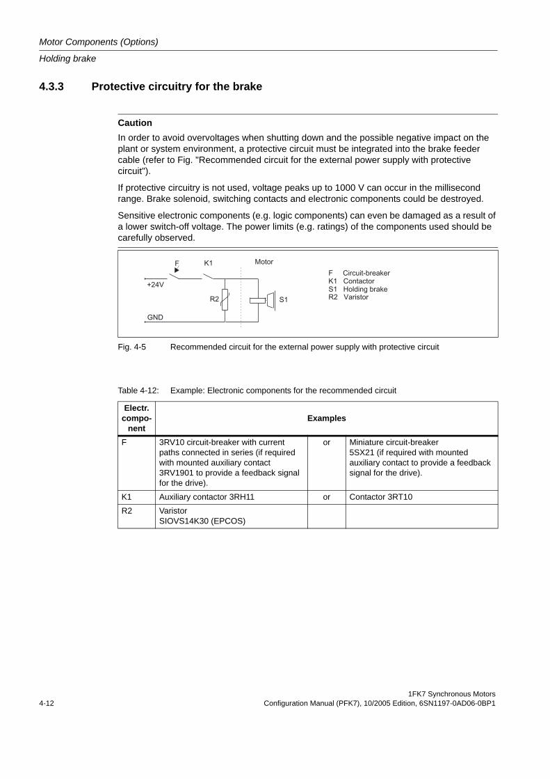
Motor Components (Options)
Holding brake
1FK7 Synchronous Motors4-12 Configuration Manual (PFK7), 10/2005 Edition, 6SN1197-0AD06-0BP1
4.3.3 Protective circuitry for the brake
Fig. 4-5 Recommended circuit for the external power supply with protective circuit
CautionIn order to avoid overvoltages when shutting down and the possible negative impact on the plant or system environment, a protective circuit must be integrated into the brake feeder cable (refer to Fig. "Recommended circuit for the external power supply with protective circuit").
If protective circuitry is not used, voltage peaks up to 1000 V can occur in the millisecond range. Brake solenoid, switching contacts and electronic components could be destroyed.
Sensitive electronic components (e.g. logic components) can even be damaged as a result of a lower switch-off voltage. The power limits (e.g. ratings) of the components used should be carefully observed.
Table 4-12: Example: Electronic components for the recommended circuit
Electr.compo-
nentExamples
F 3RV10 circuit-breaker with current paths connected in series (if required with mounted auxiliary contact 3RV1901 to provide a feedback signal for the drive).
or Miniature circuit-breaker 5SX21 (if required with mounted auxiliary contact to provide a feedback signal for the drive).
K1 Auxiliary contactor 3RH11 or Contactor 3RT10
R2 Varistor SIOVS14K30 (EPCOS)
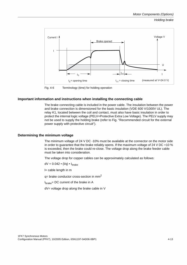
1FK7 Synchronous MotorsConfiguration Manual (PFK7), 10/2005 Edition, 6SN1197-0AD06-0BP1 4-13
Motor Components (Options)
Holding brake
Fig. 4-6 Terminology (time) for holding operation
Important information and instructions when installing the connecting cableThe brake connecting cable is included in the power cable. The insulation between the power and brake connection is dimensioned for the basic insulation (VDE 600 V/1000V UL). The relay K1, located between the coil and contact, must also have basic insulation in order to protect the internal logic voltage (PELV=Protective Extra Low Voltage). The PELV supply may not be used to supply the holding brake (refer to Fig. "Recommended circuit for the external power supply with protective circuit").
Determining the minimum voltageThe minimum voltage of 24 V DC -10% must be available at the connector on the motor side in order to guarantee that the brake reliably opens. If the maximum voltage of 24 V DC +10 % is exceeded, then the brake could re-close. The voltage drop along the brake feeder cable must be taken into consideration.
The voltage drop for copper cables can be approximately calculated as follows:
dV = 0.042 • (l/q) • Ibrake
l= cable length in m
q= brake conductor cross-section in mm2
Ibrake= DC current of the brake in A
dV= voltage drop along the brake cable in V
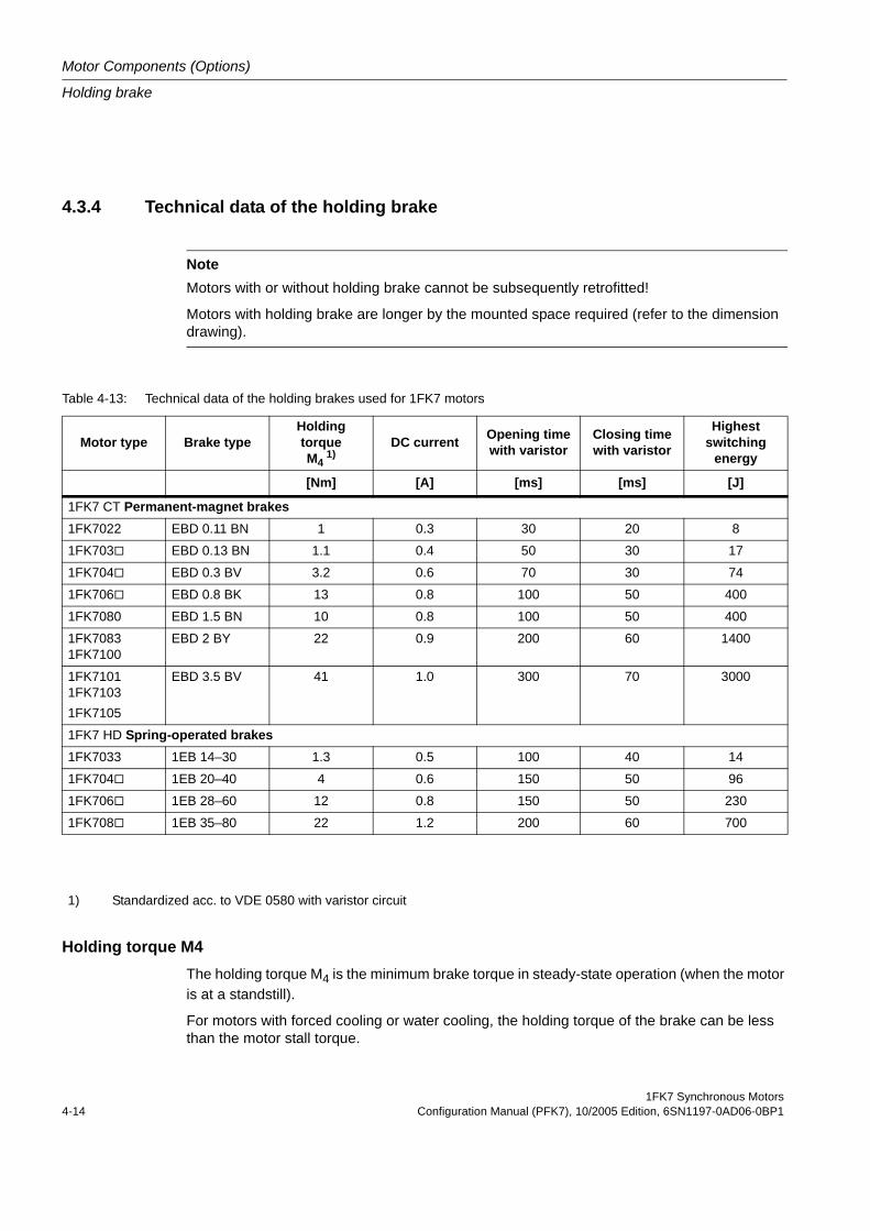
Motor Components (Options)
Holding brake
1FK7 Synchronous Motors4-14 Configuration Manual (PFK7), 10/2005 Edition, 6SN1197-0AD06-0BP1
4.3.4 Technical data of the holding brake
Holding torque M4The holding torque M4 is the minimum brake torque in steady-state operation (when the motor is at a standstill).
For motors with forced cooling or water cooling, the holding torque of the brake can be less than the motor stall torque.
NoteMotors with or without holding brake cannot be subsequently retrofitted!
Motors with holding brake are longer by the mounted space required (refer to the dimension drawing).
Table 4-13: Technical data of the holding brakes used for 1FK7 motors
Motor type Brake typeHolding torqueM4
1)DC current Opening time
with varistorClosing timewith varistor
Highest switching
energy
[Nm] [A] [ms] [ms] [J]
1FK7 CT Permanent-magnet brakes1FK7022 EBD 0.11 BN 1 0.3 30 20 8
1FK703 EBD 0.13 BN 1.1 0.4 50 30 17
1FK704 EBD 0.3 BV 3.2 0.6 70 30 74
1FK706 EBD 0.8 BK 13 0.8 100 50 400
1FK7080 EBD 1.5 BN 10 0.8 100 50 400
1FK70831FK7100
EBD 2 BY 22 0.9 200 60 1400
1FK71011FK71031FK7105
EBD 3.5 BV 41 1.0 300 70 3000
1FK7 HD Spring-operated brakes1FK7033 1EB 14–30 1.3 0.5 100 40 14
1FK704 1EB 20–40 4 0.6 150 50 96
1FK706 1EB 28–60 12 0.8 150 50 230
1FK708 1EB 35–80 22 1.2 200 60 700
1) Standardized acc. to VDE 0580 with varistor circuit
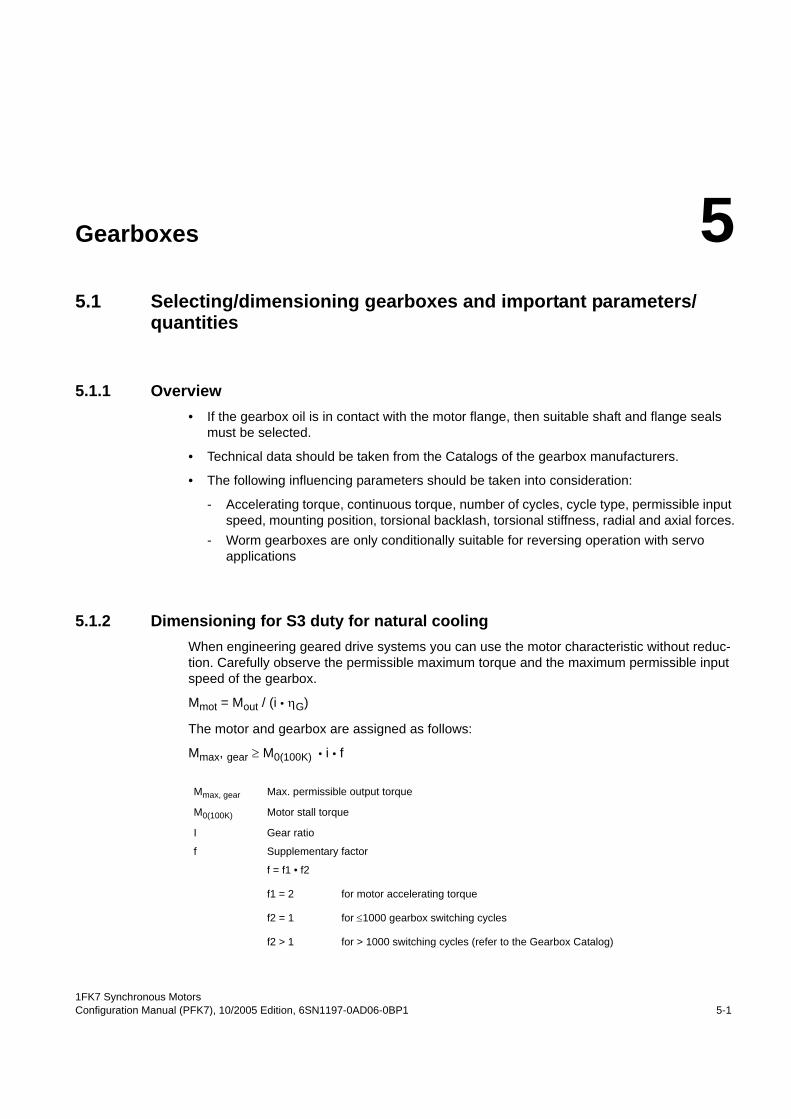
1FK7 Synchronous MotorsConfiguration Manual (PFK7), 10/2005 Edition, 6SN1197-0AD06-0BP1 5-1
Gearboxes 55.1 Selecting/dimensioning gearboxes and important parameters/
quantities
5.1.1 Overview• If the gearbox oil is in contact with the motor flange, then suitable shaft and flange seals
must be selected.
• Technical data should be taken from the Catalogs of the gearbox manufacturers.
• The following influencing parameters should be taken into consideration:
- Accelerating torque, continuous torque, number of cycles, cycle type, permissible input speed, mounting position, torsional backlash, torsional stiffness, radial and axial forces.
- Worm gearboxes are only conditionally suitable for reversing operation with servo applications
5.1.2 Dimensioning for S3 duty for natural coolingWhen engineering geared drive systems you can use the motor characteristic without reduc-tion. Carefully observe the permissible maximum torque and the maximum permissible input speed of the gearbox.
Mmot = Mout / (i • ηG)
The motor and gearbox are assigned as follows:
Mmax, gear ≥ M0(100K) • i • f
Mmax, gear Max. permissible output torque
M0(100K) Motor stall torque
I Gear ratio
f Supplementary factor
f = f1 • f2
f1 = 2 for motor accelerating torque
f2 = 1 for ≤1000 gearbox switching cycles
f2 > 1 for > 1000 switching cycles (refer to the Gearbox Catalog)
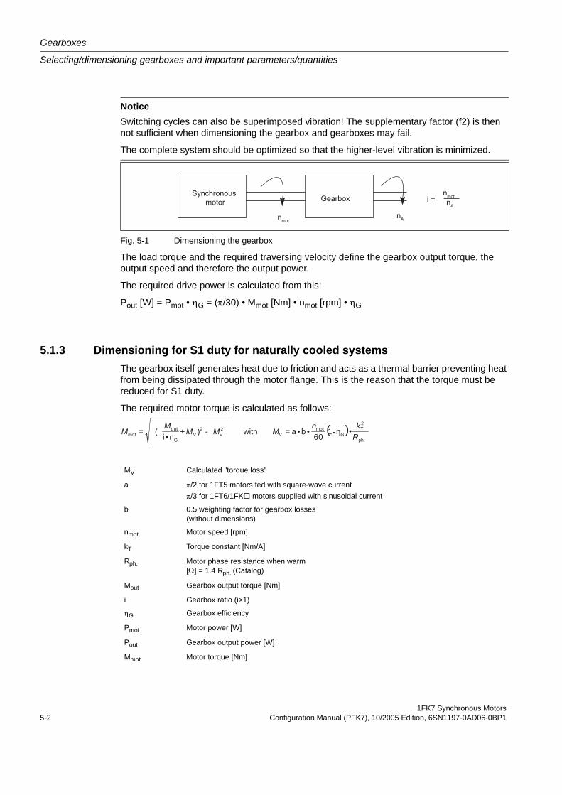
Gearboxes
Selecting/dimensioning gearboxes and important parameters/quantities
1FK7 Synchronous Motors5-2 Configuration Manual (PFK7), 10/2005 Edition, 6SN1197-0AD06-0BP1
Fig. 5-1 Dimensioning the gearbox
The load torque and the required traversing velocity define the gearbox output torque, the output speed and therefore the output power.
The required drive power is calculated from this:
Pout [W] = Pmot • ηG = (π/30) • Mmot [Nm] • nmot [rpm] • ηG
5.1.3 Dimensioning for S1 duty for naturally cooled systemsThe gearbox itself generates heat due to friction and acts as a thermal barrier preventing heat from being dissipated through the motor flange. This is the reason that the torque must be reduced for S1 duty.
The required motor torque is calculated as follows:
NoticeSwitching cycles can also be superimposed vibration! The supplementary factor (f2) is then not sufficient when dimensioning the gearbox and gearboxes may fail.
The complete system should be optimized so that the higher-level vibration is minimized.
MV Calculated "torque loss"
a π/2 for 1FT5 motors fed with square-wave currentπ/3 for 1FT6/1FK motors supplied with sinusoidal current
b 0.5 weighting factor for gearbox losses(without dimensions)
nmot Motor speed [rpm]
kT Torque constant [Nm/A]
Rph. Motor phase resistance when warm [Ω] = 1.4 Rph. (Catalog)
Mout Gearbox output torque [Nm]
i Gearbox ratio (i>1)
ηG Gearbox efficiency
Pmot Motor power [W]
Pout Gearbox output power [W]
Mmot Motor torque [Nm]
( ) 2
2 2 • 1 6 0
• b • a = ) + • i
( = R k n
M M M M
M --
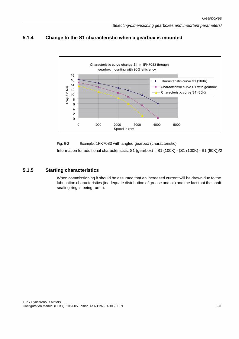
1FK7 Synchronous MotorsConfiguration Manual (PFK7), 10/2005 Edition, 6SN1197-0AD06-0BP1 5-3
Gearboxes
Selecting/dimensioning gearboxes and important parameters/
5.1.4 Change to the S1 characteristic when a gearbox is mounted
Fig. 5-2 Example: 1FK7083 with angled gearbox (characteristic)
Information for additional characteristics: S1 (gearbox) = S1 (100K) - (S1 (100K) - S1 (60K))/2
5.1.5 Starting characteristicsWhen commissioning it should be assumed that an increased current will be drawn due to the lubrication characteristics (inadequate distribution of grease and oil) and the fact that the shaft sealing ring is being run-in.
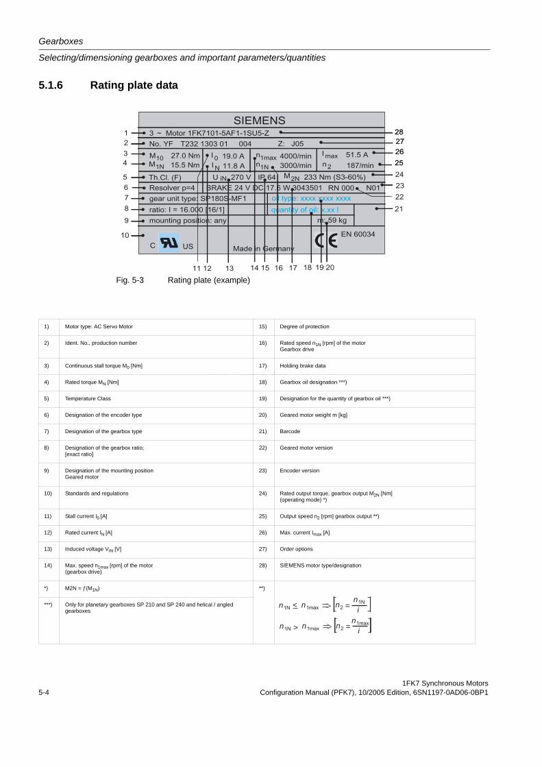
Gearboxes
Selecting/dimensioning gearboxes and important parameters/quantities
1FK7 Synchronous Motors5-4 Configuration Manual (PFK7), 10/2005 Edition, 6SN1197-0AD06-0BP1
n < n n =ni
n > n n =n
i
5.1.6 Rating plate data
Fig. 5-3 Rating plate (example)
1) Motor type: AC Servo Motor 15) Degree of protection
2) Ident. No., production number 16) Rated speed n1N [rpm] of the motorGearbox drive
3) Continuous stall torque M0 [Nm] 17) Holding brake data
4) Rated torque MN [Nm] 18) Gearbox oil designation ***)
5) Temperature Class 19) Designation for the quantity of gearbox oil ***)
6) Designation of the encoder type 20) Geared motor weight m [kg]
7) Designation of the gearbox type 21) Barcode
8) Designation of the gearbox ratio;[exact ratio]
22) Geared motor version
9) Designation of the mounting positionGeared motor
23) Encoder version
10) Standards and regulations 24) Rated output torque, gearbox output M2N [Nm](operating mode) *)
11) Stall current I0 [A] 25) Output speed n2 [rpm] gearbox output **)
12) Rated current IN [A] 26) Max. current Imax [A]
13) Induced voltage VIN [V] 27) Order options
14) Max. speed n1max [rpm] of the motor(gearbox drive)
28) SIEMENS motor type/designation
*) M2N = ƒ(M1N) **)
***) Only for planetary gearboxes SP 210 and SP 240 and helical / angled gearboxes
n < n n =ni
n > n n =n
i
1FK7 Synchronous MotorsConfiguration Manual (PFK7), 10/2005 Edition, 6SN1197-0AD06-0BP1 5-5
Gearboxes
Helical and angled gearboxes
5.2 Helical and angled gearboxes
5.2.1 Features
5.2.1.1 Overview1FK7 geared motors are preassembled as a complete unit and supplied with a gearbox filled with oil. The range of types includes:
• Helical geared motors with 9 gearbox sizes
• Offset shaft geared motors with 5 gearbox sizes
• Bevel geared motors with 8 gearbox sizes, and
• Worm geared motors with 5 gearbox sizes
A wide range of mounting possibilities can be implemented with the numerous options.
1FK7 geared motors are designed for operation without external cooling and the heat is dissi-pated through the motor surface. 1FK7 geared motors can be combined with the SIMOVERT MASTERDRIVES Motion Control drive system to create a powerful system with a high degree of functionality. Integrated encoder systems for speed and position can be selected depending on the application just as for 1FK7 servomotors.
Gearboxes
Helical and angled gearboxes
1FK7 Synchronous Motors5-6 Configuration Manual (PFK7), 10/2005 Edition, 6SN1197-0AD06-0BP1
5.2.1.2 Benefits1FK7 geared motors offer:
• Extremely compact design as a result of the direct mounting (because there is no coupling cage between the motor and gearbox)
• Maintenance-free and lubricated for life (exception, worm gearboxes)
• High efficiency
• Low torsional backlash
• Low running noise thanks to the low running noise due to the helical gearing
• High endurance gearing (exception, worm gearboxes)
• Suitable for cyclic operation with alternating load and continuous operation
• Favorably-priced solution when compared to planetary geared motors
5.2.1.3 Applications1FK7 geared motors are admirably suited for applications in general machinery construction for basic positioning tasks and auxiliary drives with servo quality that continually operate, for example in:
• Packaging machines
• High-bay racking units
• Wood, glass, ceramic and stone working machines
• Beverage filling plants
• Conveyor beltsTable 5-1: Engineering
To engineer geared motors and as selection and ordering tool, a CD-ROM with the program "CAD CREATOR" can be used (Order No. 6SL7033-0AA00-0AG0) or online through the Internet.
www.siemens.com/cad-creator
All data, dimension drawings and 3D-CAD files for the 1FK7 geared motors are provided here.
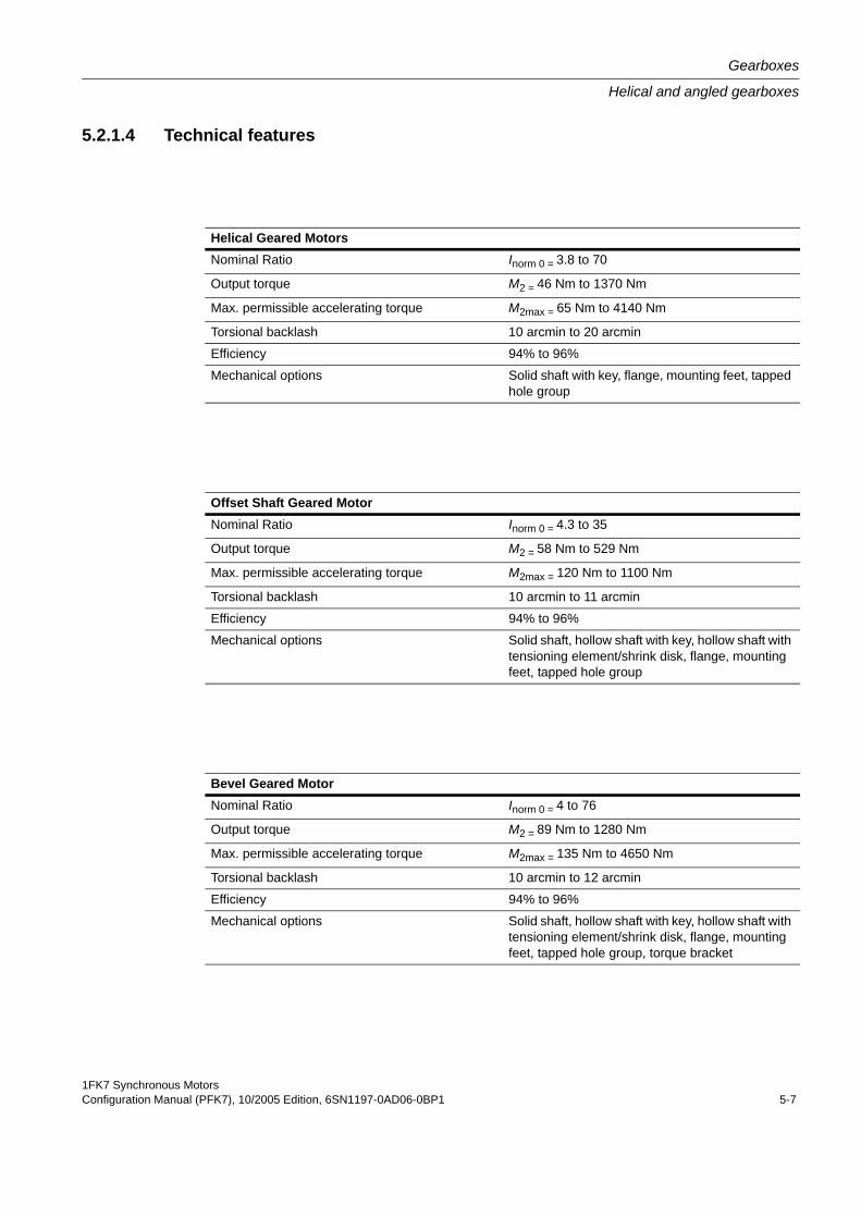
1FK7 Synchronous MotorsConfiguration Manual (PFK7), 10/2005 Edition, 6SN1197-0AD06-0BP1 5-7
Gearboxes
Helical and angled gearboxes
5.2.1.4 Technical features
Helical Geared MotorsNominal Ratio Inorm 0 = 3.8 to 70
Output torque M2 = 46 Nm to 1370 Nm
Max. permissible accelerating torque M2max = 65 Nm to 4140 Nm
Torsional backlash 10 arcmin to 20 arcmin
Efficiency 94% to 96%
Mechanical options Solid shaft with key, flange, mounting feet, tapped hole group
Offset Shaft Geared MotorNominal Ratio Inorm 0 = 4.3 to 35
Output torque M2 = 58 Nm to 529 Nm
Max. permissible accelerating torque M2max = 120 Nm to 1100 Nm
Torsional backlash 10 arcmin to 11 arcmin
Efficiency 94% to 96%
Mechanical options Solid shaft, hollow shaft with key, hollow shaft with tensioning element/shrink disk, flange, mounting feet, tapped hole group
Bevel Geared MotorNominal Ratio Inorm 0 = 4 to 76
Output torque M2 = 89 Nm to 1280 Nm
Max. permissible accelerating torque M2max = 135 Nm to 4650 Nm
Torsional backlash 10 arcmin to 12 arcmin
Efficiency 94% to 96%
Mechanical options Solid shaft, hollow shaft with key, hollow shaft with tensioning element/shrink disk, flange, mounting feet, tapped hole group, torque bracket
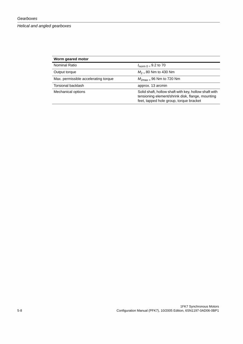
Gearboxes
Helical and angled gearboxes
1FK7 Synchronous Motors5-8 Configuration Manual (PFK7), 10/2005 Edition, 6SN1197-0AD06-0BP1
Worm geared motorNominal Ratio Inorm 0 = 9.2 to 70
Output torque M2 = 80 Nm to 430 Nm
Max. permissible accelerating torque M2max = 96 Nm to 720 Nm
Torsional backlash approx. 13 arcmin
Mechanical options Solid shaft, hollow shaft with key, hollow shaft with tensioning element/shrink disk, flange, mounting feet, tapped hole group, torque bracket
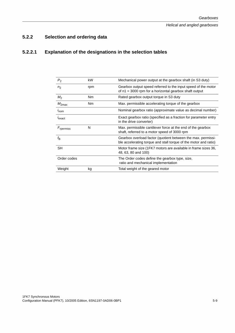
1FK7 Synchronous MotorsConfiguration Manual (PFK7), 10/2005 Edition, 6SN1197-0AD06-0BP1 5-9
Gearboxes
Helical and angled gearboxes
5.2.2 Selection and ordering data
5.2.2.1 Explanation of the designations in the selection tables
P2 kW Mechanical power output at the gearbox shaft (in S3 duty)
n2 rpm Gearbox output speed referred to the input speed of the motor of n1 = 3000 rpm for a horizontal gearbox shaft output
M2 Nm Rated gearbox output torque in S3 duty
M2max Nm Max. permissible accelerating torque of the gearbox
inom Nominal gearbox ratio (approximate value as decimal number)
iexact Exact gearbox ratio (specified as a fraction for parameter entry in the drive converter)
Frpermiss N Max. permissible cantilever force at the end of the gearbox shaft, referred to a motor speed of 3000 rpm
fB Gearbox overload factor (quotient between the max. permissi-ble accelerating torque and stall torque of the motor and ratio)
SH Motor frame size (1FK7 motors are available in frame sizes 36, 48, 63, 80 and 100)
Order codes The Order codes define the gearbox type, size, ratio and mechanical implementation
Weight kg Total weight of the geared motor
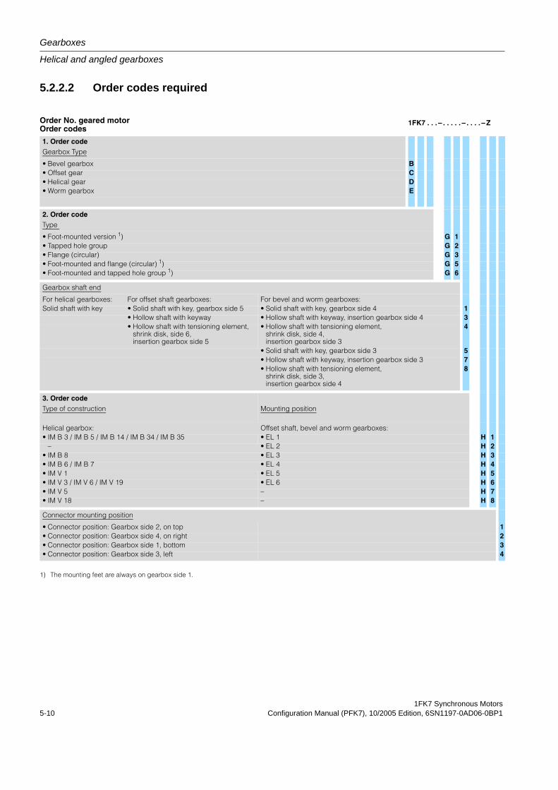
Gearboxes
Helical and angled gearboxes
1FK7 Synchronous Motors5-10 Configuration Manual (PFK7), 10/2005 Edition, 6SN1197-0AD06-0BP1
5.2.2.2 Order codes required
Order No. geared motorOrder codes
1FK7 . . . – . . . . . – . . . . – Z
1. Order codeGearbox Type
• Bevel gearbox B• Offset gear C• Helical gear D• Worm gearbox E
2. Order codeType
• Foot-mounted version 1) G 1• Tapped hole group G 2• Flange (circular) G 3• Foot-mounted and flange (circular) 1) G 5• Foot-mounted and tapped hole group 1) G 6
Gearbox shaft end
For helical gearboxes: For offset shaft gearboxes: For bevel and worm gearboxes:Solid shaft with key • Solid shaft with key, gearbox side 5 • Solid shaft with key, gearbox side 4 1
• Hollow shaft with keyway • Hollow shaft with keyway, insertion gearbox side 4 3• Hollow shaft with tensioning element,
shrink disk, side 6,insertion gearbox side 5
• Hollow shaft with tensioning element, shrink disk, side 4,insertion gearbox side 3
4
• Solid shaft with key, gearbox side 3 5• Hollow shaft with keyway, insertion gearbox side 3 7• Hollow shaft with tensioning element,
shrink disk, side 3,insertion gearbox side 4
8
3. Order codeType of construction Mounting position
Helical gearbox: Offset shaft, bevel and worm gearboxes:• IM B 3 / IM B 5 / IM B 14 / IM B 34 / IM B 35 • EL 1 H 1
– • EL 2 H 2• IM B 8 • EL 3 H 3• IM B 6 / IM B 7 • EL 4 H 4• IM V 1 • EL 5 H 5• IM V 3 / IM V 6 / IM V 19 • EL 6 H 6• IM V 5 – H 7• IM V 18 – H 8
Connector mounting position
• Connector position: Gearbox side 2, on top 1• Connector position: Gearbox side 4, on right 2• Connector position: Gearbox side 1, bottom 3• Connector position: Gearbox side 3, left 4
1) The mounting feet are always on gearbox side 1.
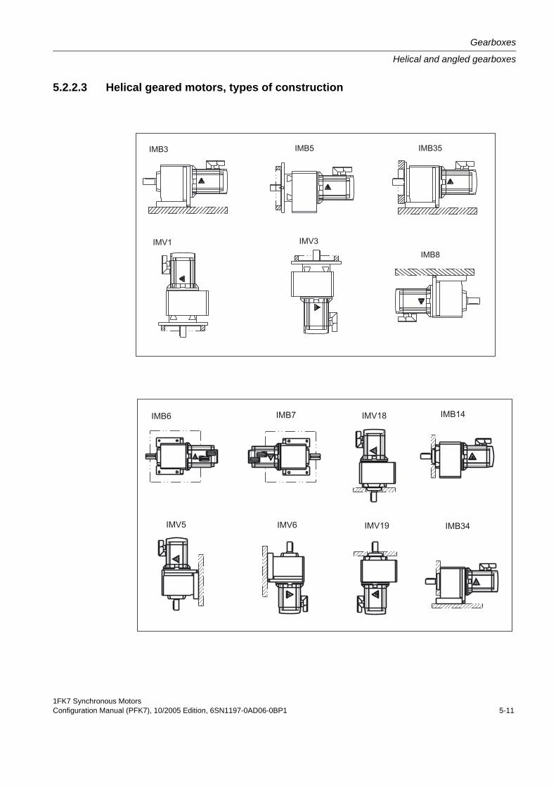
1FK7 Synchronous MotorsConfiguration Manual (PFK7), 10/2005 Edition, 6SN1197-0AD06-0BP1 5-11
Gearboxes
Helical and angled gearboxes
5.2.2.3 Helical geared motors, types of construction
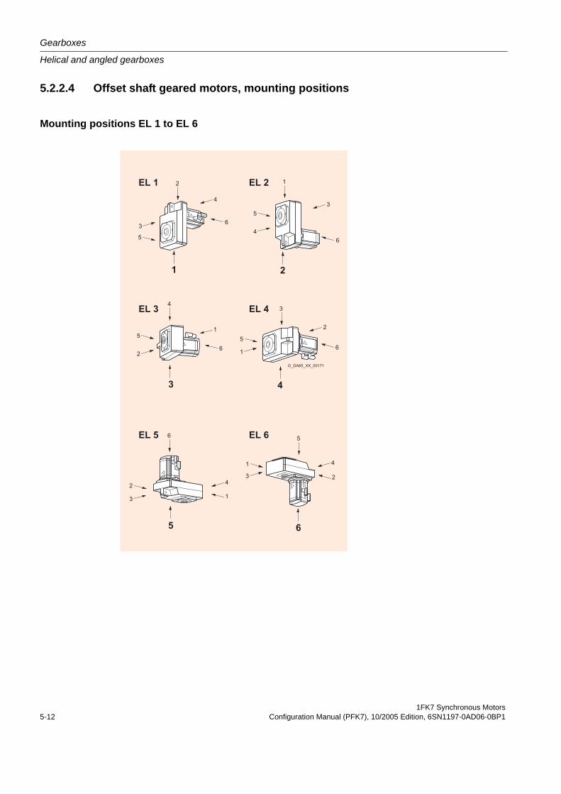
Gearboxes
Helical and angled gearboxes
1FK7 Synchronous Motors5-12 Configuration Manual (PFK7), 10/2005 Edition, 6SN1197-0AD06-0BP1
5.2.2.4 Offset shaft geared motors, mounting positions
Mounting positions EL 1 to EL 6
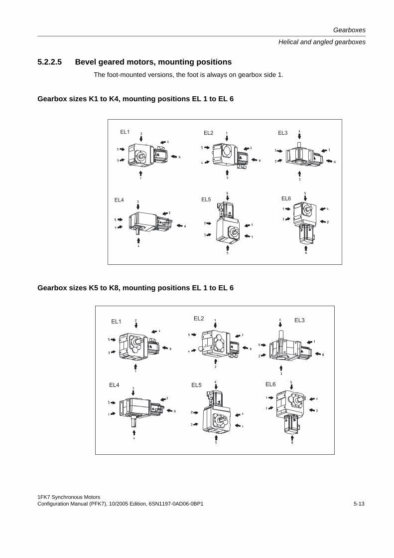
1FK7 Synchronous MotorsConfiguration Manual (PFK7), 10/2005 Edition, 6SN1197-0AD06-0BP1 5-13
Gearboxes
Helical and angled gearboxes
5.2.2.5 Bevel geared motors, mounting positionsThe foot-mounted versions, the foot is always on gearbox side 1.
Gearbox sizes K1 to K4, mounting positions EL 1 to EL 6
Gearbox sizes K5 to K8, mounting positions EL 1 to EL 6
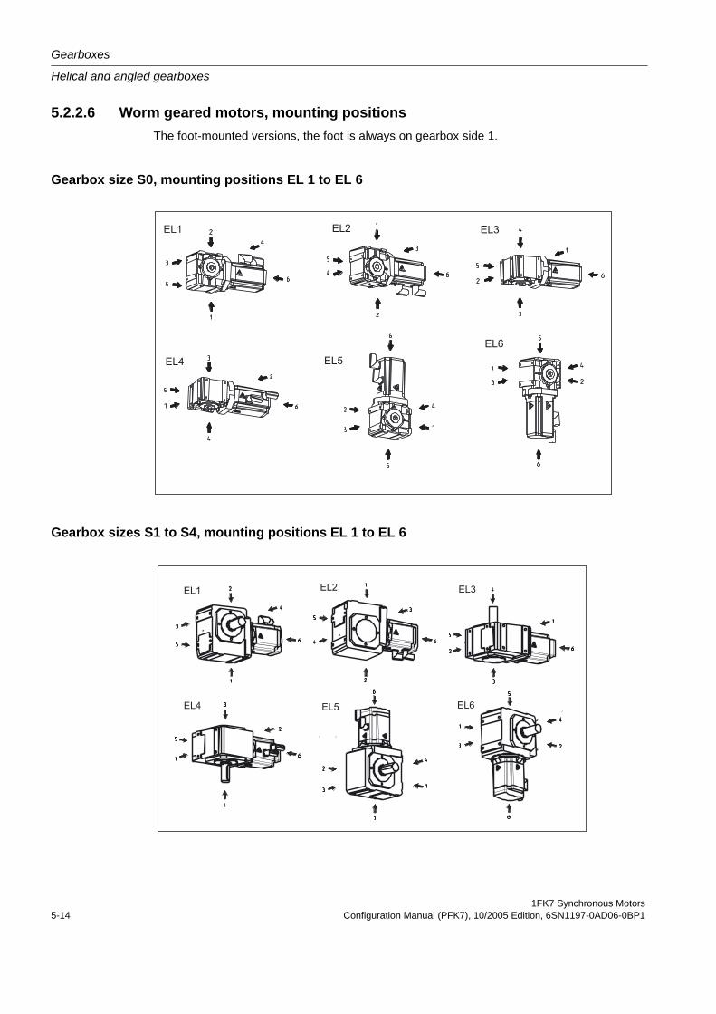
Gearboxes
Helical and angled gearboxes
1FK7 Synchronous Motors5-14 Configuration Manual (PFK7), 10/2005 Edition, 6SN1197-0AD06-0BP1
5.2.2.6 Worm geared motors, mounting positionsThe foot-mounted versions, the foot is always on gearbox side 1.
Gearbox size S0, mounting positions EL 1 to EL 6
Gearbox sizes S1 to S4, mounting positions EL 1 to EL 6
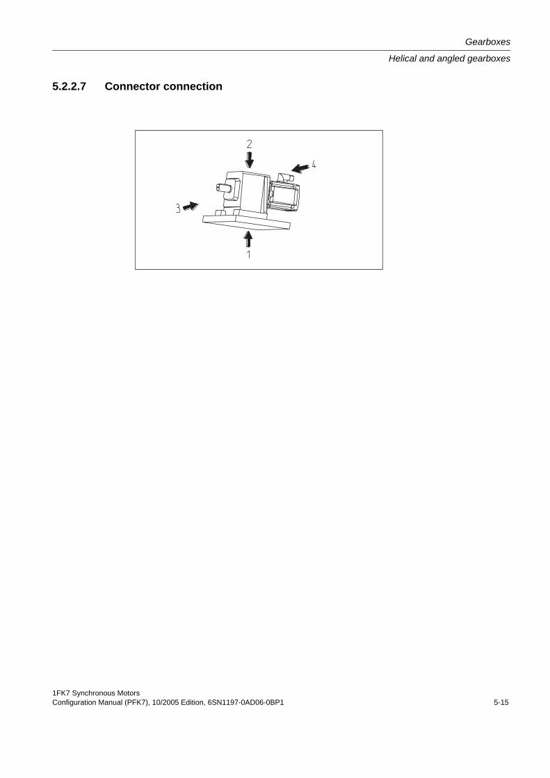
1FK7 Synchronous MotorsConfiguration Manual (PFK7), 10/2005 Edition, 6SN1197-0AD06-0BP1 5-15
Gearboxes
Helical and angled gearboxes
5.2.2.7 Connector connection
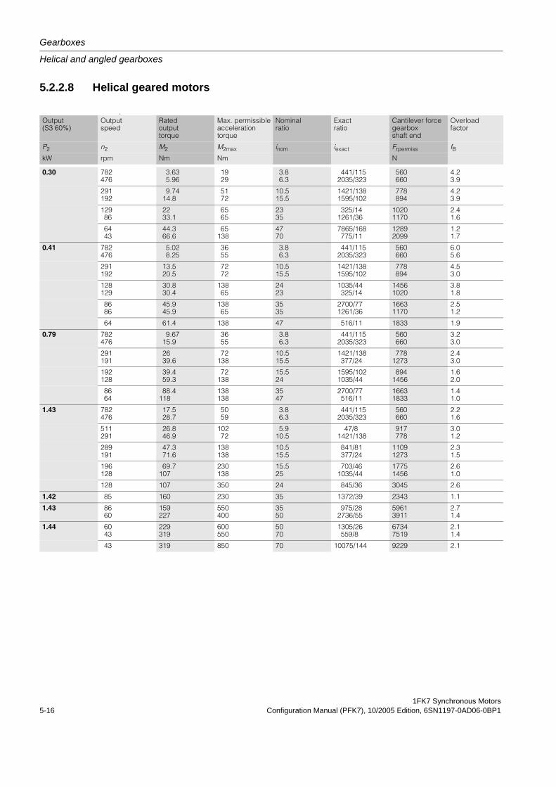
Gearboxes
Helical and angled gearboxes
1FK7 Synchronous Motors5-16 Configuration Manual (PFK7), 10/2005 Edition, 6SN1197-0AD06-0BP1
5.2.2.8 Helical geared motors
A
Output (S3 60%)
Output speed
Rated output torque
Max. permissible acceleration torque
Nominal ratio
Exact ratio
Cantilever force gearbox shaft end
Overload factor
P2 n2 M2 M2max inom iexact Frpermiss fBkW rpm Nm Nm N
0.30 782476
3.635.96
1929
3.86.3
441/1152035/323
560660
4.23.9
291192
9.7414.8
5172
10.515.5
1421/1381595/102
778894
4.23.9
12986
2233.1
6565
2335
325/141261/36
10201170
2.41.6
6443
44.366.6
65138
4770
7865/168775/11
12892099
1.21.7
0.41 782476
5.028.25
3655
3.86.3
441/1152035/323
560660
6.05.6
291192
13.520.5
7272
10.515.5
1421/1381595/102
778894
4.53.0
128129
30.830.4
13865
2423
1035/44325/14
14561020
3.81.8
8686
45.945.9
13865
3535
2700/771261/36
16631170
2.51.2
64 61.4 138 47 516/11 1833 1.9
0.79 782476
9.6715.9
3655
3.86.3
441/1152035/323
560660
3.23.0
291191
2639.6
72138
10.515.5
1421/138377/24
7781273
2.43.0
192128
39.459.3
72138
15.524
1595/1021035/44
8941456
1.62.0
8664
88.4118
138138
3547
2700/77516/11
16631833
1.41.0
1.43 782476
17.528.7
5059
3.86.3
441/1152035/323
560660
2.21.6
511291
26.846.9
10272
5.910.5
47/81421/138
917778
3.01.2
289191
47.371.6
138138
10.515.5
841/81377/24
11091273
2.31.5
196128
69.7107
230138
15.525
703/461035/44
17751456
2.61.0
128 107 350 24 845/36 3045 2.6
1.42 85 160 230 35 1372/39 2343 1.1
1.43 8660
159227
550400
3550
975/282736/55
59613911
2.71.4
1.44 6043
229319
600550
5070
1305/26559/8
67347519
2.11.4
43 319 850 70 10075/144 9229 2.1

1FK7 Synchronous MotorsConfiguration Manual (PFK7), 10/2005 Edition, 6SN1197-0AD06-0BP1 5-17
Gearboxes
Helical and angled gearboxes
Gearbox size Motor frame size Helical geared motors Order codes Total weight, approx.kgSH
Order No. Gearbox type Type Type of construction mounting position
C002C002
3636
1FK7032 – 5AK71 – 11FK7032 – 5AK71 – 1
7
7
7
7
55
––
ZZ
D01D02
GG7
7
7
7
HH7
7
7
7
8.68.6
C002C002
3636
1FK7032 – 5AK71 – 11FK7032 – 5AK71 – 1
7
7
7
7
55
––
ZZ
D03D04
GG7
7
7
7
HH7
7
7
7
8.68.6
C002C002
3636
1FK7032 – 5AK71 – 11FK7032 – 5AK71 – 1
7
7
7
7
55
––
ZZ
D05D06
GG7
7
7
7
HH7
7
7
7
8.68.6
C002C102
3636
1FK7032 – 5AK71 – 11FK7032 – 5AK71 – 1
7
7
7
7
55
––
ZZ
D07D18
GG7
7
7
7
HH7
7
7
7
8.613.5
C002C002
4848
1FK7040 – 5AK71 – 11FK7040 – 5AK71 – 1
7
7
7
7
55
––
ZZ
D01D02
GG7
7
7
7
HH7
7
7
7
9.49.4
C002C002
4848
1FK7040 – 5AK71 – 11FK7040 – 5AK71 – 1
7
7
7
7
55
––
ZZ
D03D04
GG7
7
7
7
HH7
7
7
7
9.49.4
C102C002
4848
1FK7040 – 5AK71 – 11FK7040 – 5AK71 – 1
7
7
7
7
55
––
ZZ
D15D05
GG7
7
7
7
HH7
7
7
7
14.39.4
C102C002
4848
1FK7040 – 5AK71 – 11FK7040 – 5AK71 – 1
7
7
7
7
55
––
ZZ
D16D06
GG7
7
7
7
HH7
7
7
7
14.39.4
C102 48 1FK7040 – 5AK71 – 17 7 5 – Z D17 G7 7 H 7 7 14.3
C002C002
4848
1FK7042 – 5AF71 – 11FK7042 – 5AF71 – 1
7
7
7
7
55
––
ZZ
D01D02
GG7
7
7
7
HH7
7
7
7
10.710.7
C002C102
4848
1FK7042 – 5AF71 – 11FK7042 – 5AF71 – 1
7
7
7
7
55
––
ZZ
D03D14
GG7
7
7
7
HH7
7
7
7
10.715.6
C002C102
4848
1FK7042 – 5AF71 – 11FK7042 – 5AF71 – 1
7
7
7
7
55
––
ZZ
D04D15
GG7
7
7
7
HH7
7
7
7
10.715.6
C102C102
4848
1FK7042 – 5AF71 – 11FK7042 – 5AF71 – 1
7
7
7
7
55
––
ZZ
D16D17
GG7
7
7
7
HH7
7
7
7
15.615.6
C002C002
6363
1FK7060 – 5AF71 – 11FK7060 – 5AF71 – 1
7
7
7
7
55
––
ZZ
D01D02
GG7
7
7
7
HH7
7
7
7
13.413.4
C102C002
6363
1FK7060 – 5AF71 – 11FK7060 – 5AF71 – 1
7
7
7
7
55
––
ZZ
D12D03
GG7
7
7
7
HH7
7
7
7
18.313.4
C102C102
6363
1FK7060 – 5AF71 – 11FK7060 – 5AF71 – 1
7
7
7
7
55
––
ZZ
D13D14
GG7
7
7
7
HH7
7
7
7
18.318.3
C202C102
6363
1FK7060 – 5AF71 – 11FK7060 – 5AF71 – 1
7
7
7
7
55
––
ZZ
D24D15
GG7
7
7
7
HH7
7
7
7
22.318.3
C302 63 1FK7060 – 5AF71 – 1 7 7 5 – Z D35 G7 7 H 7 7 27.4
C202 63 1FK7060 – 5AF71 – 1 7 7 5 – Z D26 G7 7 H 7 7 22.3
C402C302
6363
1FK7060 – 5AF71 – 11FK7060 – 5AF71 – 1
7
7
7
7
55
––
ZZ
D46D37
GG7
7
7
7
HH7
7
7
7
37.627.4
C402C402
6363
1FK7060 – 5AF71 – 11FK7060 – 5AF71 – 1
7
7
7
7
55
––
ZZ
D47D48
GG7
7
7
7
HH7
7
7
7
37.637.6
C502 63 1FK7060 – 5AF71 – 1 7 7 5 – Z D58 G7 7 H 7 7 49.2
• Encoder systemin the motor:
Incremental encoder sin/cos 1 VppAbsolute encoder EnDat 2,048 pulses/revolution (shaft height 48 and higher)Absolute encoder EnDat 512 pulses/revolution(only shaft height 36)Simple absolute encoder EnDat 32 pulses/revolution (shaft height 48 and higher)Resolver, multipole (pole number = pole number for motor)Resolver, 2 pole
AE
H
G
S
T
• Holding brake: Motor without holding brakeMotor with holding brake
UV
Refer to the required Order codes and helical geared motors, types of construction
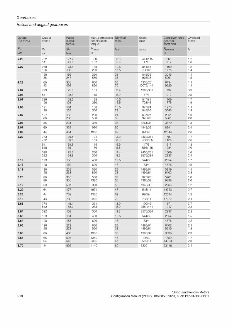
Gearboxes
Helical and angled gearboxes
1FK7 Synchronous Motors5-18 Configuration Manual (PFK7), 10/2005 Edition, 6SN1197-0AD06-0BP1
Output (S3 60%)
Output speed
Rated output torque
Max. permissible acceleration torque
Nominal ratio
Exact ratio
Cantilever force gearbox shaft end
Overload factor
P2 n2 M2 M2max inom iexact Frpermiss fBkW rpm Nm Nm N
2.23 782511
27.241.6
50102
3.85.9
441/11547/8
560917
1.21.6
2.22 289196
73.5108
138230
10.515.5
841/81703/46
11091775
1.21.4
12886
166247
350550
2335
845/36975/28
30455961
1.41.5
2.23 6043
355495
600850
5070
1305/2610075/144
67349229
1.11.1
2.07 773 25.6 101 3.9 1363/351 799 3.3
2.08 511 38.8 115 5.9 47/8 917 2.5
2.07 289196
68.5101
138230
10.515.5
847/81703/46
11091775
1.71.9
2.08 191128
104155
138350
15.523
377/24845/36
12733045
1.11.9
2.07 12786
156230
230550
2435
637/27975/28
20515961
1.32.0
2.08 86 231 350 35 1261/36 3479 1.3
2.07 60 329 920 50 1943/39 8241 2.4
2.09 44 454 1380 69 620/9 12344 2.6
3.20 773772
39.539.6
101154
3.93.9
1363/351486/125
7991125
1.72.5
511518
59.859
115176
5.95.8
47/8666/115
9171284
1.32.0
320322
95.694.8
230350
9.49.3
2450/2613575/384
15092237
1.62.4
3.19 193 158 400 15.5 544/35 2654 1.7
3.18 190 160 600 16 63/4 4576 2.5
3.19 128128
238238
550850
2323
1495/641495/64
52196402
1.52.3
3.20 8686
355355
5501380
3535
975/281360/39
59619838
1.02.6
3.19 60 507 920 50 1943/39 2265 1.2
3.20 64 477 1971 47 515/11 14923 2.7
3.23 44 702 1380 69 620/9 12344 1.3
3.19 43 708 2300 70 765/11 17027 2.1
3.66 774512
45.168.2
251288
3.95.9
190/492584/441
16711917
3.72.8
3.64 322 108 350 9.3 3575/384 2237 2.2
3.66 193 181 400 15.5 544/35 2654 1.5
3.64 190 183 600 16 63/4 4576 2.2
3.65 128128
272272
850550
2323
1495/641495/64
64025219
2.11.3
3.66 86 406 1380 35 1360/39 9838 2.3
3.65 6664
528545
13802300
4547
136/3515/11
185214923
1.72.8
3.70 44 802 4140 69 6209 23146 3.4
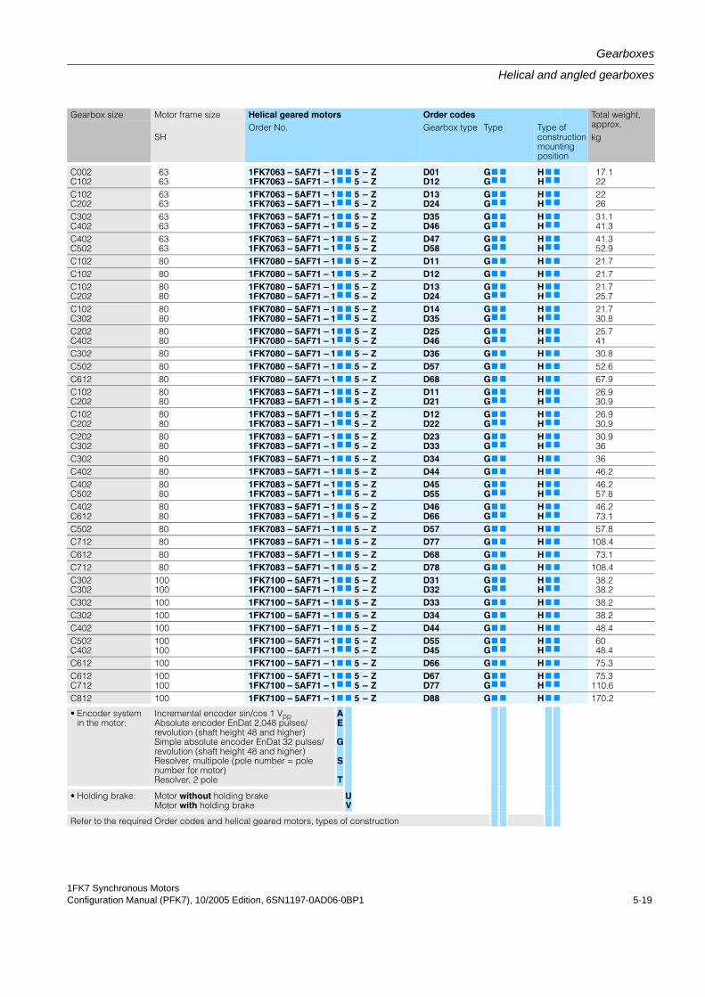
1FK7 Synchronous MotorsConfiguration Manual (PFK7), 10/2005 Edition, 6SN1197-0AD06-0BP1 5-19
Gearboxes
Helical and angled gearboxes
Gearbox size Motor frame size Helical geared motors Order codes Total weight, approx.kgSH
Order No. Gearbox type Type Type of construction mounting position
C002C102
6363
1FK7063 – 5AF71 – 11FK7063 – 5AF71 – 1
7
7
7
7
55
––
ZZ
D01D12
GG7
7
7
7
HH7
7
7
7
17.122
C102C202
6363
1FK7063 – 5AF71 – 11FK7063 – 5AF71 – 1
7
7
7
7
55
––
ZZ
D13D24
GG7
7
7
7
HH7
7
7
7
2226
C302C402
6363
1FK7063 – 5AF71 – 11FK7063 – 5AF71 – 1
7
7
7
7
55
––
ZZ
D35D46
GG7
7
7
7
HH7
7
7
7
31.141.3
C402C502
6363
1FK7063 – 5AF71 – 11FK7063 – 5AF71 – 1
7
7
7
7
55
––
ZZ
D47D58
GG7
7
7
7
HH7
7
7
7
41.352.9
C102 80 1FK7080 – 5AF71 – 17 7 5 – Z D11 G7 7 H 7 7 21.7C102 80 1FK7080 – 5AF71 – 17 7 5 – Z D12 G7 7 H 7 7 21.7C102C202
8080
1FK7080 – 5AF71 – 11FK7080 – 5AF71 – 1
7
7
7
7
55
––
ZZ
D13D24
GG7
7
7
7
HH7
7
7
7
21.725.7
C102C302
8080
1FK7080 – 5AF71 – 11FK7080 – 5AF71 – 1
7
7
7
7
55
––
ZZ
D14D35
GG7
7
7
7
HH7
7
7
7
21.730.8
C202C402
8080
1FK7080 – 5AF71 – 11FK7080 – 5AF71 – 1
7
7
7
7
55
––
ZZ
D25D46
GG7
7
7
7
HH7
7
7
7
25.741
C302 80 1FK7080 – 5AF71 – 17 7 5 – Z D36 G7 7 H 7 7 30.8C502 80 1FK7080 – 5AF71 – 17 7 5 – Z D57 G7 7 H 7 7 52.6C612 80 1FK7080 – 5AF71 – 17 7 5 – Z D68 G7 7 H 7 7 67.9C102C202
8080
1FK7083 – 5AF71 – 11FK7083 – 5AF71 – 1
7
7
7
7
55
––
ZZ
D11D21
GG7
7
7
7
HH7
7
7
7
26.930.9
C102C202
8080
1FK7083 – 5AF71 – 11FK7083 – 5AF71 – 1
7
7
7
7
55
––
ZZ
D12D22
GG7
7
7
7
HH7
7
7
7
26.930.9
C202C302
8080
1FK7083 – 5AF71 – 11FK7083 – 5AF71 – 1
7
7
7
7
55
––
ZZ
D23D33
GG7
7
7
7
HH7
7
7
7
30.936
C302 80 1FK7083 – 5AF71 – 17 7 5 – Z D34 G7 7 H 7 7 36C402 80 1FK7083 – 5AF71 – 17 7 5 – Z D44 G7 7 H 7 7 46.2C402C502
8080
1FK7083 – 5AF71 – 11FK7083 – 5AF71 – 1
7
7
7
7
55
––
ZZ
D45D55
GG7
7
7
7
HH7
7
7
7
46.257.8
C402C612
8080
1FK7083 – 5AF71 – 11FK7083 – 5AF71 – 1
7
7
7
7
55
––
ZZ
D46D66
GG7
7
7
7
HH7
7
7
7
46.273.1
C502 80 1FK7083 – 5AF71 – 17 7 5 – Z D57 G7 7 H 7 7 57.8C712 80 1FK7083 – 5AF71 – 17 7 5 – Z D77 G7 7 H 7 7 108.4C612 80 1FK7083 – 5AF71 – 17 7 5 – Z D68 G7 7 H 7 7 73.1C712 80 1FK7083 – 5AF71 – 17 7 5 – Z D78 G7 7 H 7 7 108.4C302C302
100100
1FK7100 – 5AF71 – 11FK7100 – 5AF71 – 1
7
7
7
7
55
––
ZZ
D31D32
GG7
7
7
7
HH7
7
7
7
38.238.2
C302 100 1FK7100 – 5AF71 – 17 7 5 – Z D33 G7 7 H 7 7 38.2C302 100 1FK7100 – 5AF71 – 17 7 5 – Z D34 G7 7 H 7 7 38.2C402 100 1FK7100 – 5AF71 – 17 7 5 – Z D44 G7 7 H 7 7 48.4C502C402
100100
1FK7100 – 5AF71 – 11FK7100 – 5AF71 – 1
7
7
7
7
55
––
ZZ
D55D45
GG7
7
7
7
HH7
7
7
7
6048.4
C612 100 1FK7100 – 5AF71 – 17 7 5 – Z D66 G7 7 H 7 7 75.3C612C712
100100
1FK7100 – 5AF71 – 11FK7100 – 5AF71 – 1
7
7
7
7
55
––
ZZ
D67D77
GG7
7
7
7
HH7
7
7
7
75.3110.6
C812 100 1FK7100 – 5AF71 – 17 7 5 – Z D88 G7 7 H 7 7 170.2
• Encoder systemin the motor:
Incremental encoder sin/cos 1 VppAbsolute encoder EnDat 2,048 pulses/revolution (shaft height 48 and higher)Simple absolute encoder EnDat 32 pulses/revolution (shaft height 48 and higher)Resolver, multipole (pole number = pole number for motor)Resolver, 2 pole
AE
G
S
T
• Holding brake: Motor without holding brakeMotor with holding brake
UV
Refer to the required Order codes and helical geared motors, types of construction
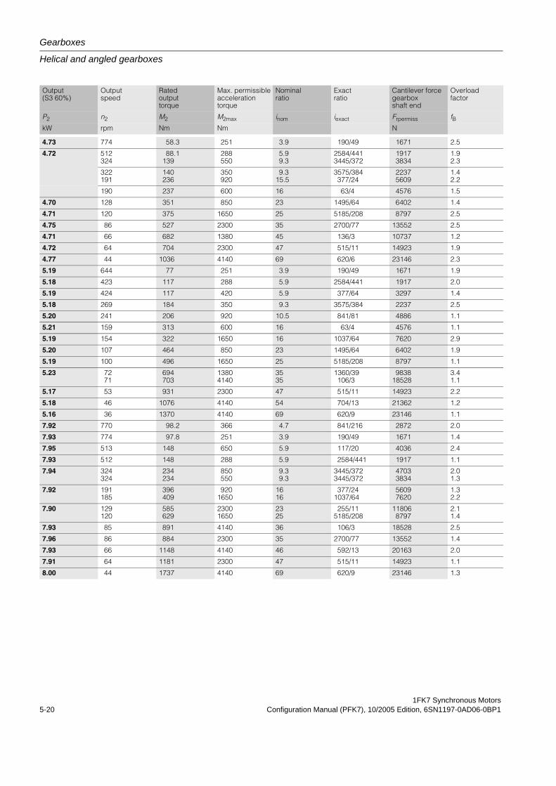
Gearboxes
Helical and angled gearboxes
1FK7 Synchronous Motors5-20 Configuration Manual (PFK7), 10/2005 Edition, 6SN1197-0AD06-0BP1
Output (S3 60%)
Output speed
Rated output torque
Max. permissible acceleration torque
Nominal ratio
Exact ratio
Cantilever force gearbox shaft end
Overload factor
P2 n2 M2 M2max inom iexact Frpermiss fBkW rpm Nm Nm N
4.73 774 58.3 251 3.9 190/49 1671 2.5
4.72 512324
88.1139
288550
5.99.3
2584/4413445/372
19173834
1.92.3
322191
140236
350920
9.315.5
3575/384377/24
22375609
1.42.2
190 237 600 16 63/4 4576 1.5
4.70 128 351 850 23 1495/64 6402 1.4
4.71 120 375 1650 25 5185/208 8797 2.5
4.75 86 527 2300 35 2700/77 13552 2.5
4.71 66 682 1380 45 136/3 10737 1.2
4.72 64 704 2300 47 515/11 14923 1.9
4.77 44 1036 4140 69 620/6 23146 2.3
5.19 644 77 251 3.9 190/49 1671 1.9
5.18 423 117 288 5.9 2584/441 1917 2.0
5.19 424 117 420 5.9 377/64 3297 1.4
5.18 269 184 350 9.3 3575/384 2237 2.5
5.20 241 206 920 10.5 841/81 4886 1.1
5.21 159 313 600 16 63/4 4576 1.1
5.19 154 322 1650 16 1037/64 7620 2.9
5.20 107 464 850 23 1495/64 6402 1.9
5.19 100 496 1650 25 5185/208 8797 1.1
5.23 7271
694703
13804140
3535
1360/39106/3
983818528
3.41.1
5.17 53 931 2300 47 515/11 14923 2.2
5.18 46 1076 4140 54 704/13 21362 1.2
5.16 36 1370 4140 69 620/9 23146 1.1
7.92 770 98.2 366 4.7 841/216 2872 2.0
7.93 774 97.8 251 3.9 190/49 1671 1.4
7.95 513 148 650 5.9 117/20 4036 2.4
7.93 512 148 288 5.9 2584/441 1917 1.1
7.94 324324
234234
850550
9.39.3
3445/3723445/372
47033834
2.01.3
7.92 191185
396409
9201650
1616
377/241037/64
56097620
1.32.2
7.90 129120
585629
23001650
2325
255/115185/208
118068797
2.11.4
7.93 85 891 4140 36 106/3 18528 2.5
7.96 86 884 2300 35 2700/77 13552 1.4
7.93 66 1148 4140 46 592/13 20163 2.0
7.91 64 1181 2300 47 515/11 14923 1.1
8.00 44 1737 4140 69 620/9 23146 1.3

1FK7 Synchronous MotorsConfiguration Manual (PFK7), 10/2005 Edition, 6SN1197-0AD06-0BP1 5-21
Gearboxes
Helical and angled gearboxes
Gearbox size Motor frame size Helical geared motors Order codes Total weight, approx.kgSH
Order No. Gearbox type Type Type of construction mounting position
C302 100 1FK7100 – 5AF71 – 17 7 5 – Z D31 G7 7 H 7 7 43.8
C302C402
100100
1FK7100 – 5AF71 – 11FK7100 – 5AF71 – 1
7
7
7
7
55
––
ZZ
D32D43
GG7
7
7
7
HH7
7
7
7
43.843.8
C302C502
100100
1FK7100 – 5AF71 – 11FK7100 – 5AF71 – 1
7
7
7
7
55
––
ZZ
D33D54
GG7
7
7
7
HH7
7
7
7
5465.6
C402 100 1FK7100 – 5AF71 – 17 7 5 – Z D44 G7 7 H 7 7 54
C502 100 1FK7100 – 5AF71 – 17 7 5 – Z D55 G7 7 H 7 7 65.6
C612 100 1FK7100 – 5AF71 – 17 7 5 – Z D65 G7 7 H 7 7 80.9
C712 100 1FK7100 – 5AF71 – 17 7 5 – Z D76 G7 7 H 7 7 116.2
C612 100 1FK7100 – 5AF71 – 17 7 5 – Z D67 G7 7 H 7 7 80.9
C712 100 1FK7100 – 5AF71 – 17 7 5 – Z D77 G7 7 H 7 7 116.2
C812 100 1FK7100 – 5AF71 – 17 7 5 – Z D88 G7 7 H 7 7 175.8
C302 100 1FK7103 – 5AF71 – 17 7 5 – Z D31 G7 7 H 7 7 50.4
C302 100 1FK7103 – 5AF71 – 17 7 5 – Z D32 G7 7 H 7 7 50.4
C402 100 1FK7103 – 5AF71 – 17 7 5 – Z D42 G7 7 H 7 7 60.6
C302 100 1FK7103 – 5AF71 – 17 7 5 – Z D33 G7 7 H 7 7 50.4
C502 100 1FK7103 – 5AF71 – 17 7 5 – Z D53 G7 7 H 7 7 72.2
C402 100 1FK7103 – 5AF71 – 17 7 5 – Z D44 G7 7 H 7 7 60.6
C612 100 1FK7103 – 5AF71 – 17 7 5 – Z D64 G7 7 H 7 7 87.5
C502 100 1FK7103 – 5AF71 – 17 7 5 – Z D55 G7 7 H 7 7 72.2
C612 100 1FK7103 – 5AF71 – 17 7 5 – Z D65 G7 7 H 7 7 87.5
C612C812
100100
1FK7103 – 5AF71 – 11FK7103 – 5AF71 – 1
7
7
7
7
55
––
ZZ
D66D86
GG7
7
7
7
HH7
7
7
7
87.5182.4
C712 100 1FK7103 – 5AF71 – 17 7 5 – Z D77 G7 7 H 7 7 122.8
C812 100 1FK7103 – 5AF71 – 17 7 5 – Z D87 G7 7 H 7 7 182.4
C812 100 1FK7103 – 5AF71 – 17 7 5 – Z D88 G7 7 H 7 7 182.4
C402 100 1FK7105 – 5AF71 – 17 7 5 – Z D41 G7 7 H 7 7 70.6
C302 100 1FK7105 – 5AF71 – 17 7 5 – Z D31 G7 7 H 7 7 60.4
C502 100 1FK7105 – 5AF71 – 17 7 5 – Z D52 G7 7 H 7 7 82.2
C302 100 1FK7105 – 5AF71 – 17 7 5 – Z D32 G7 7 H 7 7 53.3
C502C402
100100
1FK7105 – 5AF71 – 11FK7105 – 5AF71 – 1
7
7
7
7
55
––
ZZ
D53D43
GG7
7
7
7
HH7
7
7
7
82.270.6
C502C612
100100
1FK7105 – 5AF71 – 11FK7105 – 5AF71 – 1
7
7
7
7
55
––
ZZ
D54D64
GG7
7
7
7
HH7
7
7
7
82.297.5
C712C612
100100
1FK7105 – 5AF71 – 11FK7105 – 5AF71 – 1
7
7
7
7
55
––
ZZ
D75D65
GG7
7
7
7
HH7
7
7
7
132.897.5
C812 100 1FK7105 – 5AF71 – 17 7 5 – Z D86 G7 7 H 7 7 192.4
C712 100 1FK7105 – 5AF71 – 17 7 5 – Z D76 G7 7 H 7 7 132.8
C812 100 1FK7105 – 5AF71 – 17 7 5 – Z D87 G7 7 H 7 7 192.4
C712 100 1FK7105 – 5AF71 – 17 7 5 – Z D77 G7 7 H 7 7 132.8
C812 100 1FK7105 – 5AF71 – 17 7 5 – Z D88 G7 7 H 7 7 192.4
• Encoder systemin the motor:
Incremental encoder sin/cos 1 VppAbsolute encoder EnDat 2,048 pulses/revolution (shaft height 48 and higher)Simple absolute encoder EnDat 32 pulses/revolution (shaft height 48 and higher)Resolver, multipole (pole number = pole number for motor)Resolver, 2 pole
AE
G
S
T
• Holding brake: Motor without holding brakeMotor with holding brake
UV
Refer to the required Order codes and helical geared motors, types of construction
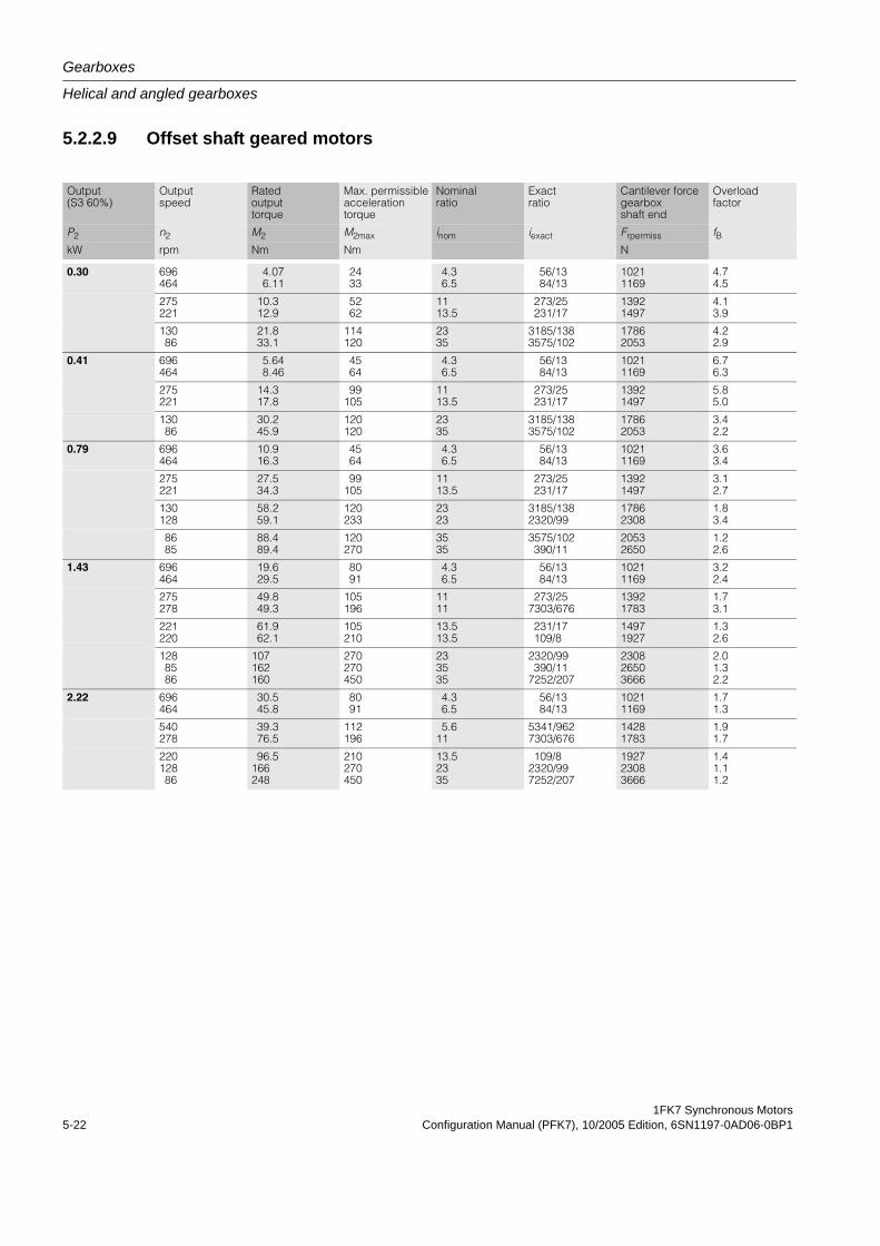
Gearboxes
Helical and angled gearboxes
1FK7 Synchronous Motors5-22 Configuration Manual (PFK7), 10/2005 Edition, 6SN1197-0AD06-0BP1
5.2.2.9 Offset shaft geared motors
Output (S3 60%)
Output speed
Rated output torque
Max. permissible acceleration torque
Nominal ratio
Exact ratio
Cantilever force gearbox shaft end
Overload factor
P2 n2 M2 M2max inom iexact Frpermiss fBkW rpm Nm Nm N
0.30 696464
4.076.11
2433
4.36.5
56/1384/13
10211169
4.74.5
275221
10.312.9
5262
1113.5
273/25231/17
13921497
4.13.9
13086
21.833.1
114120
2335
3185/1383575/102
17862053
4.22.9
0.41 696464
5.648.46
4564
4.36.5
56/1384/13
10211169
6.76.3
275221
14.317.8
99105
1113.5
273/25231/17
13921497
5.85.0
13086
30.245.9
120120
2335
3185/1383575/102
17862053
3.42.2
0.79 696464
10.916.3
4564
4.36.5
56/1384/13
10211169
3.63.4
275221
27.534.3
99105
1113.5
273/25231/17
13921497
3.12.7
130128
58.259.1
120233
2323
3185/1382320/99
17862308
1.83.4
8685
88.489.4
120270
3535
3575/102390/11
20532650
1.22.6
1.43 696464
19.629.5
8091
4.36.5
56/1384/13
10211169
3.22.4
275278
49.849.3
105196
1111
273/257303/676
13921783
1.73.1
221220
61.962.1
105210
13.513.5
231/17109/8
14971927
1.32.6
1288586
107162160
270270450
233535
2320/99390/11
7252/207
230826503666
2.01.32.2
2.22 696464
30.545.8
8091
4.36.5
56/1384/13
10211169
1.71.3
540278
39.376.5
112196
5.611
5341/9627303/676
14281783
1.91.7
22012886
96.5166248
210270450
13.52335
109/82320/997252/207
192723083666
1.41.11.2
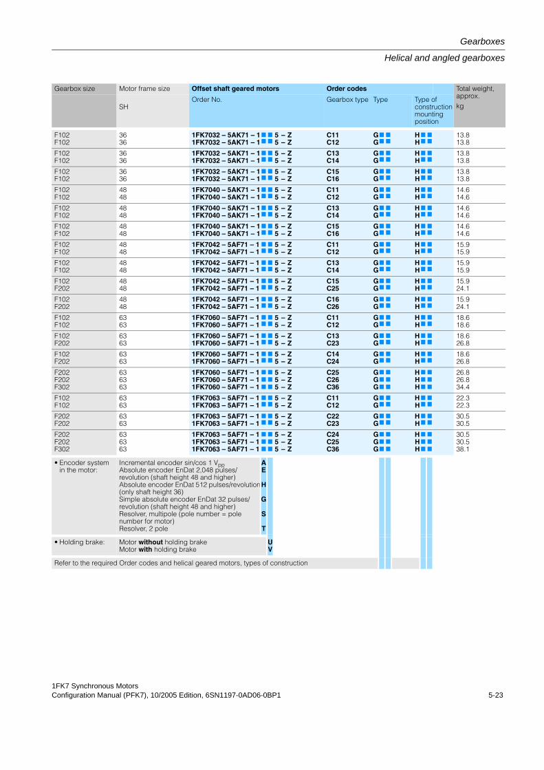
1FK7 Synchronous MotorsConfiguration Manual (PFK7), 10/2005 Edition, 6SN1197-0AD06-0BP1 5-23
Gearboxes
Helical and angled gearboxes
Gearbox size Motor frame size Offset shaft geared motors Order codes Total weight, approx.kgSH
Order No. Gearbox type Type Type of construction mounting position
F102F102
3636
1FK7032 – 5AK71 – 11FK7032 – 5AK71 – 1
7
7
7
7
55
––
ZZ
C11C12
GG7
7
7
7
HH7
7
7
7
13.813.8
F102F102
3636
1FK7032 – 5AK71 – 11FK7032 – 5AK71 – 1
7
7
7
7
55
––
ZZ
C13C14
GG7
7
7
7
HH7
7
7
7
13.813.8
F102F102
3636
1FK7032 – 5AK71 – 11FK7032 – 5AK71 – 1
7
7
7
7
55
––
ZZ
C15C16
GG7
7
7
7
HH7
7
7
7
13.813.8
F102F102
4848
1FK7040 – 5AK71 – 11FK7040 – 5AK71 – 1
7
7
7
7
55
––
ZZ
C11C12
GG7
7
7
7
HH7
7
7
7
14.614.6
F102F102
4848
1FK7040 – 5AK71 – 11FK7040 – 5AK71 – 1
7
7
7
7
55
––
ZZ
C13C14
GG7
7
7
7
HH7
7
7
7
14.614.6
F102F102
4848
1FK7040 – 5AK71 – 11FK7040 – 5AK71 – 1
7
7
7
7
55
––
ZZ
C15C16
GG7
7
7
7
HH7
7
7
7
14.614.6
F102F102
4848
1FK7042 – 5AF71 – 11FK7042 – 5AF71 – 1
7
7
7
7
55
––
ZZ
C11C12
GG7
7
7
7
HH7
7
7
7
15.915.9
F102F102
4848
1FK7042 – 5AF71 – 11FK7042 – 5AF71 – 1
7
7
7
7
55
––
ZZ
C13C14
GG7
7
7
7
HH7
7
7
7
15.915.9
F102F202
4848
1FK7042 – 5AF71 – 11FK7042 – 5AF71 – 1
7
7
7
7
55
––
ZZ
C15C25
GG7
7
7
7
HH7
7
7
7
15.924.1
F102F202
4848
1FK7042 – 5AF71 – 11FK7042 – 5AF71 – 1
7
7
7
7
55
––
ZZ
C16C26
GG7
7
7
7
HH7
7
7
7
15.924.1
F102F102
6363
1FK7060 – 5AF71 – 11FK7060 – 5AF71 – 1
7
7
7
7
55
––
ZZ
C11C12
GG7
7
7
7
HH7
7
7
7
18.618.6
F102F202
6363
1FK7060 – 5AF71 – 11FK7060 – 5AF71 – 1
7
7
7
7
55
––
ZZ
C13C23
GG7
7
7
7
HH7
7
7
7
18.626.8
F102F202
6363
1FK7060 – 5AF71 – 11FK7060 – 5AF71 – 1
7
7
7
7
55
––
ZZ
C14C24
GG7
7
7
7
HH7
7
7
7
18.626.8
F202F202F302
636363
1FK7060 – 5AF71 – 11FK7060 – 5AF71 – 11FK7060 – 5AF71 – 1
7
7
7
7
7
7
555
–––
ZZZ
C25C26C36
GGG
7
7
7
7
7
7
HHH
7
7
7
7
7
7
26.826.834.4
F102F102
6363
1FK7063 – 5AF71 – 11FK7063 – 5AF71 – 1
7
7
7
7
55
––
ZZ
C11C12
GG7
7
7
7
HH7
7
7
7
22.322.3
F202F202
6363
1FK7063 – 5AF71 – 11FK7063 – 5AF71 – 1
7
7
7
7
55
––
ZZ
C22C23
GG7
7
7
7
HH7
7
7
7
30.530.5
F202F202F302
636363
1FK7063 – 5AF71 – 11FK7063 – 5AF71 – 11FK7063 – 5AF71 – 1
7
7
7
7
7
7
555
–––
ZZZ
C24C25C36
GGG
7
7
7
7
7
7
HHH
7
7
7
7
7
7
30.530.538.1
• Encoder systemin the motor:
Incremental encoder sin/cos 1 VppAbsolute encoder EnDat 2,048 pulses/revolution (shaft height 48 and higher)Absolute encoder EnDat 512 pulses/revolution(only shaft height 36)Simple absolute encoder EnDat 32 pulses/revolution (shaft height 48 and higher)Resolver, multipole (pole number = pole number for motor)Resolver, 2 pole
AE
H
G
S
T
• Holding brake: Motor without holding brakeMotor with holding brake
UV
Refer to the required Order codes and helical geared motors, types of construction
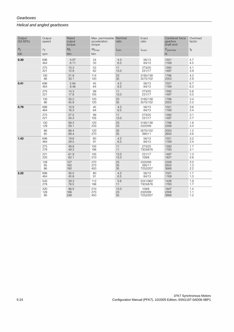
Gearboxes
Helical and angled gearboxes
1FK7 Synchronous Motors5-24 Configuration Manual (PFK7), 10/2005 Edition, 6SN1197-0AD06-0BP1
Output (S3 60%)
Output speed
Rated output torque
Max. permissible acceleration torque
Nominal ratio
Exact ratio
Cantilever force gearbox shaft end
Overload factor
P2 n2 M2 M2max inom iexact Frpermiss fBkW rpm Nm Nm N
0.30 696464
4.076.11
2433
4.36.5
56/1384/13
10211169
4.74.5
275221
10.312.9
5262
1113.5
273/25231/17
13921497
4.13.9
13086
21.833.1
114120
2335
3185/1383575/102
17862053
4.22.9
0.41 696464
5.648.46
4564
4.36.5
56/1384/13
10211169
6.76.3
275221
14.317.8
99105
1113.5
273/25231/17
13921497
5.85.0
13086
30.245.9
120120
2335
3185/1383575/102
17862053
3.42.2
0.79 696464
10.916.3
4564
4.36.5
56/1384/13
10211169
3.63.4
275221
27.534.3
99105
1113.5
273/25231/17
13921497
3.12.7
130128
58.259.1
120233
2323
3185/1382320/99
17862308
1.83.4
8685
88.489.4
120270
3535
3575/102390/11
20532650
1.22.6
1.43 696464
19.629.5
8091
4.36.5
56/1384/13
10211169
3.22.4
275278
49.849.3
105196
1111
273/257303/676
13921783
1.73.1
221220
61.962.1
105210
13.513.5
231/17109/8
14971927
1.32.6
1288586
107162160
270270450
233535
2320/99390/11
7252/207
230826503666
2.01.32.2
2.22 696464
30.545.8
8091
4.36.5
56/1384/13
10211169
1.71.3
540278
39.376.5
112196
5.611
5341/9627303/676
14281783
1.91.7
22012886
96.5166248
210270450
13.52335
109/82320/997252/207
192723083666
1.41.11.2
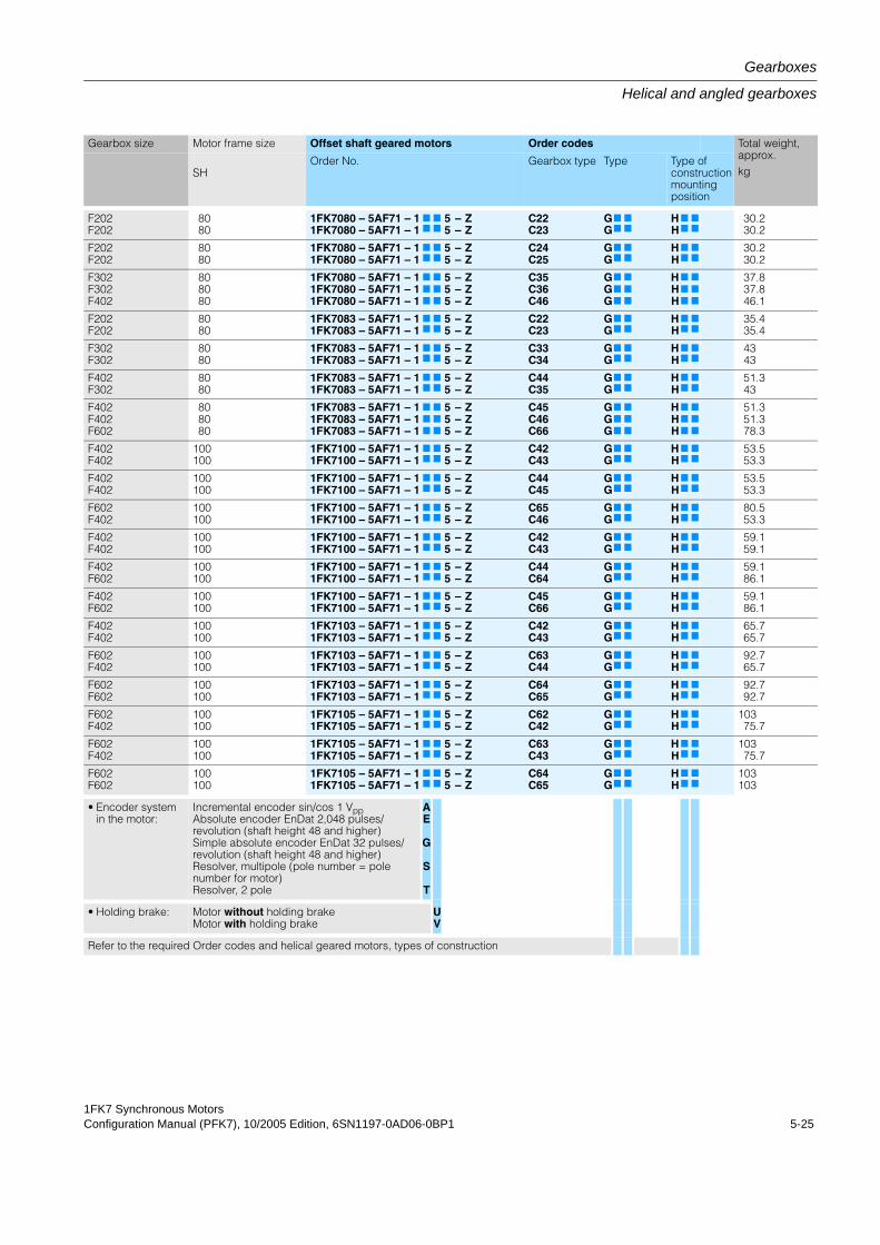
1FK7 Synchronous MotorsConfiguration Manual (PFK7), 10/2005 Edition, 6SN1197-0AD06-0BP1 5-25
Gearboxes
Helical and angled gearboxes
Gearbox size Motor frame size Offset shaft geared motors Order codes Total weight, approx.kgSH
Order No. Gearbox type Type Type of construction mounting position
F202F202
8080
1FK7080 – 5AF71 – 11FK7080 – 5AF71 – 1
7
7
7
7
55
––
ZZ
C22C23
GG7
7
7
7
HH7
7
7
7
30.230.2
F202F202
8080
1FK7080 – 5AF71 – 11FK7080 – 5AF71 – 1
7
7
7
7
55
––
ZZ
C24C25
GG7
7
7
7
HH7
7
7
7
30.230.2
F302F302F402
808080
1FK7080 – 5AF71 – 11FK7080 – 5AF71 – 11FK7080 – 5AF71 – 1
7
7
7
7
7
7
555
–––
ZZZ
C35C36C46
GGG
7
7
7
7
7
7
HHH
7
7
7
7
7
7
37.837.846.1
F202F202
8080
1FK7083 – 5AF71 – 11FK7083 – 5AF71 – 1
7
7
7
7
55
––
ZZ
C22C23
GG7
7
7
7
HH7
7
7
7
35.435.4
F302F302
8080
1FK7083 – 5AF71 – 11FK7083 – 5AF71 – 1
7
7
7
7
55
––
ZZ
C33C34
GG7
7
7
7
HH7
7
7
7
4343
F402F302
8080
1FK7083 – 5AF71 – 11FK7083 – 5AF71 – 1
7
7
7
7
55
––
ZZ
C44C35
GG7
7
7
7
HH7
7
7
7
51.343
F402F402F602
808080
1FK7083 – 5AF71 – 11FK7083 – 5AF71 – 11FK7083 – 5AF71 – 1
7
7
7
7
7
7
555
–––
ZZZ
C45C46C66
GGG
7
7
7
7
7
7
HHH
7
7
7
7
7
7
51.351.378.3
F402F402
100100
1FK7100 – 5AF71 – 11FK7100 – 5AF71 – 1
7
7
7
7
55
––
ZZ
C42C43
GG7
7
7
7
HH7
7
7
7
53.553.3
F402F402
100100
1FK7100 – 5AF71 – 11FK7100 – 5AF71 – 1
7
7
7
7
55
––
ZZ
C44C45
GG7
7
7
7
HH7
7
7
7
53.553.3
F602F402
100100
1FK7100 – 5AF71 – 11FK7100 – 5AF71 – 1
7
7
7
7
55
––
ZZ
C65C46
GG7
7
7
7
HH7
7
7
7
80.553.3
F402F402
100100
1FK7100 – 5AF71 – 11FK7100 – 5AF71 – 1
7
7
7
7
55
––
ZZ
C42C43
GG7
7
7
7
HH7
7
7
7
59.159.1
F402F602
100100
1FK7100 – 5AF71 – 11FK7100 – 5AF71 – 1
7
7
7
7
55
––
ZZ
C44C64
GG7
7
7
7
HH7
7
7
7
59.186.1
F402F602
100100
1FK7100 – 5AF71 – 11FK7100 – 5AF71 – 1
7
7
7
7
55
––
ZZ
C45C66
GG7
7
7
7
HH7
7
7
7
59.186.1
F402F402
100100
1FK7103 – 5AF71 – 11FK7103 – 5AF71 – 1
7
7
7
7
55
––
ZZ
C42C43
GG7
7
7
7
HH7
7
7
7
65.765.7
F602F402
100100
1FK7103 – 5AF71 – 11FK7103 – 5AF71 – 1
7
7
7
7
55
––
ZZ
C63C44
GG7
7
7
7
HH7
7
7
7
92.765.7
F602F602
100100
1FK7103 – 5AF71 – 11FK7103 – 5AF71 – 1
7
7
7
7
55
––
ZZ
C64C65
GG7
7
7
7
HH7
7
7
7
92.792.7
F602F402
100100
1FK7105 – 5AF71 – 11FK7105 – 5AF71 – 1
7
7
7
7
55
––
ZZ
C62C42
GG7
7
7
7
HH7
7
7
7
10375.7
F602F402
100100
1FK7105 – 5AF71 – 11FK7105 – 5AF71 – 1
7
7
7
7
55
––
ZZ
C63C43
GG7
7
7
7
HH7
7
7
7
10375.7
F602F602
100100
1FK7105 – 5AF71 – 11FK7105 – 5AF71 – 1
7
7
7
7
55
––
ZZ
C64C65
GG7
7
7
7
HH7
7
7
7
103103
• Encoder systemin the motor:
Incremental encoder sin/cos 1 VppAbsolute encoder EnDat 2,048 pulses/revolution (shaft height 48 and higher)Simple absolute encoder EnDat 32 pulses/revolution (shaft height 48 and higher)Resolver, multipole (pole number = pole number for motor)Resolver, 2 pole
AE
G
S
T
• Holding brake: Motor without holding brakeMotor with holding brake
UV
Refer to the required Order codes and helical geared motors, types of construction
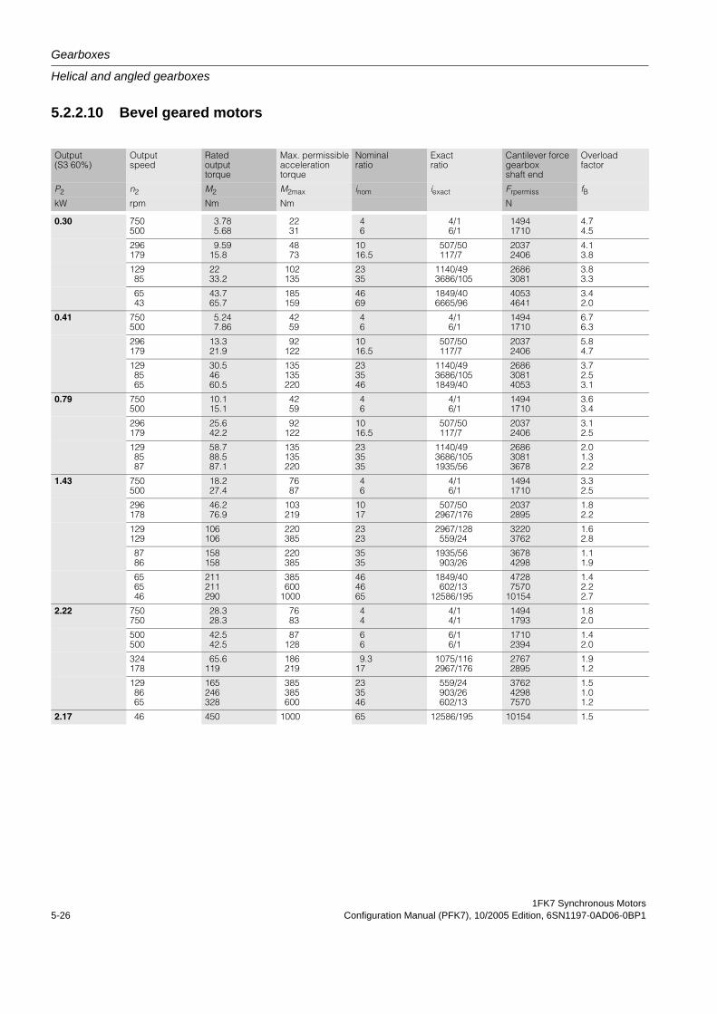
Gearboxes
Helical and angled gearboxes
1FK7 Synchronous Motors5-26 Configuration Manual (PFK7), 10/2005 Edition, 6SN1197-0AD06-0BP1
5.2.2.10 Bevel geared motors
Output (S3 60%)
Output speed
Rated output torque
Max. permissible acceleration torque
Nominal ratio
Exact ratio
Cantilever force gearbox shaft end
Overload factor
P2 n2 M2 M2max inom iexact Frpermiss fBkW rpm Nm Nm N
0.30 750500
3.785.68
2231
46
4/16/1
14941710
4.74.5
296179
9.5915.8
4873
1016.5
507/50117/7
20372406
4.13.8
12985
2233.2
102135
2335
1140/493686/105
26863081
3.83.3
6543
43.765.7
185159
4669
1849/406665/96
40534641
3.42.0
0.41 750500
5.247.86
4259
46
4/16/1
14941710
6.76.3
296179
13.321.9
92122
1016.5
507/50117/7
20372406
5.84.7
1298565
30.54660.5
135135220
233546
1140/493686/1051849/40
268630814053
3.72.53.1
0.79 750500
10.115.1
4259
46
4/16/1
14941710
3.63.4
296179
25.642.2
92122
1016.5
507/50117/7
20372406
3.12.5
1298587
58.788.587.1
135135220
233535
1140/493686/1051935/56
268630813678
2.01.32.2
1.43 750500
18.227.4
7687
46
4/16/1
14941710
3.32.5
296178
46.276.9
103219
1017
507/502967/176
20372895
1.82.2
129129
106106
220385
2323
2967/128559/24
32203762
1.62.8
8786
158158
220385
3535
1935/56903/26
36784298
1.11.9
656546
211211290
385600
1000
464665
1849/40602/13
12586/195
47287570
10154
1.42.22.7
2.22 750750
28.328.3
7683
44
4/14/1
14941793
1.82.0
500500
42.542.5
87128
66
6/16/1
17102394
1.42.0
324178
65.6119
186219
9.317
1075/1162967/176
27672895
1.91.2
1298665
165246328
385385600
233546
559/24903/26602/13
376242987570
1.51.01.2
2.17 46 450 1000 65 12586/195 10154 1.5
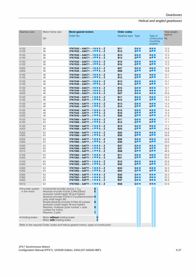
1FK7 Synchronous MotorsConfiguration Manual (PFK7), 10/2005 Edition, 6SN1197-0AD06-0BP1 5-27
Gearboxes
Helical and angled gearboxes
Gearbox size Motor frame size Bevel geared motors Order codes Total weight, approx.kgSH
Order No. Gearbox type Type Type of construction mounting position
K102K102
3636
1FK7032 – 5AK71 – 11FK7032 – 5AK71 – 1
7
7
7
7
55
––
ZZ
B11B12
GG7
7
7
7
HH7
7
7
7
12.312.3
K102K102
3636
1FK7032 – 5AK71 – 11FK7032 – 5AK71 – 1
7
7
7
7
55
––
ZZ
B13B14
GG7
7
7
7
HH7
7
7
7
12.312.3
K102K102
3636
1FK7032 – 5AK71 – 11FK7032 – 5AK71 – 1
7
7
7
7
55
––
ZZ
B15B16
GG7
7
7
7
HH7
7
7
7
12.312.3
K202K202
3636
1FK7032 – 5AK71 – 11FK7032 – 5AK71 – 1
7
7
7
7
55
––
ZZ
B27B28
GG7
7
7
7
HH7
7
7
7
19.819.8
K102K102
4848
1FK7040 – 5AK71 – 11FK7040 – 5AK71 – 1
7
7
7
7
55
––
ZZ
B11B12
GG7
7
7
7
HH7
7
7
7
13.113.1
K102K102
4848
1FK7040 – 5AK71 – 11FK7040 – 5AK71 – 1
7
7
7
7
55
––
ZZ
B13B14
GG7
7
7
7
HH7
7
7
7
13.113.1
K102K102K202
484848
1FK7040 – 5AK71 – 11FK7040 – 5AK71 – 11FK7040 – 5AK71 – 1
7
7
7
7
7
7
555
–––
ZZZ
B15B16B27
GGG
7
7
7
7
7
7
HHH
7
7
7
7
7
7
13.113.120.6
K102K102
4848
1FK7042 – 5AF71 – 11FK7042 – 5AF71 – 1
7
7
7
7
55
––
ZZ
B11B12
GG7
7
7
7
HH7
7
7
7
14.414.4
K102K102
4848
1FK7042 – 5AF71 – 11FK7042 – 5AF71 – 1
7
7
7
7
55
––
ZZ
B13B14
GG7
7
7
7
HH7
7
7
7
14.414.4
K102K102K202
484848
1FK7042 – 5AF71 – 11FK7042 – 5AF71 – 11FK7042 – 5AF71 – 1
7
7
7
7
7
7
555
–––
ZZZ
B15B16B26
GGG
7
7
7
7
7
7
HHH
7
7
7
7
7
7
14.414.421.9
K102K102
6363
1FK7060 – 5AF71 – 11FK7060 – 5AF71 – 1
7
7
7
7
55
––
ZZ
B11B12
GG7
7
7
7
HH7
7
7
7
17.117.1
K102K202
6363
1FK7060 – 5AF71 – 11FK7060 – 5AF71 – 1
7
7
7
7
55
––
ZZ
B13B24
GG7
7
7
7
HH7
7
7
7
17.124.6
K202K302
6363
1FK7060 – 5AF71 – 11FK7060 – 5AF71 – 1
7
7
7
7
55
––
ZZ
B25B35
GG7
7
7
7
HH7
7
7
7
24.629.6
K202K302
6363
1FK7060 – 5AF71 – 11FK7060 – 5AF71 – 1
7
7
7
7
55
––
ZZ
B26B36
GG7
7
7
7
HH7
7
7
7
24.629.6
K302K402K513
636363
1FK7060 – 5AF71 – 11FK7060 – 5AF71 – 11FK7060 – 5AF71 – 1
7
7
7
7
7
7
555
–––
ZZZ
B37B47B58
GGG
7
7
7
7
7
7
HHH
7
7
7
7
7
7
29.643.148.9
K102K202
6363
1FK7063 – 5AF71 – 11FK7063 – 5AF71 – 1
7
7
7
7
55
––
ZZ
B11B21
GG7
7
7
7
HH7
7
7
7
20.828.3
K102K302
6363
1FK7063 – 5AF71 – 11FK7063 – 5AF71 – 1
7
7
7
7
55
––
ZZ
B12B32
GG7
7
7
7
HH7
7
7
7
20.833.3
K302K202
6363
1FK7063 – 5AF71 – 11FK7063 – 5AF71 – 1
7
7
7
7
55
––
ZZ
B33B24
GG7
7
7
7
HH7
7
7
7
33.328.3
K302K302K402
636363
1FK7063 – 5AF71 – 11FK7063 – 5AF71 – 11FK7063 – 5AF71 – 1
7
7
7
7
7
7
555
–––
ZZZ
B35B36B47
GGG
7
7
7
7
7
7
HHH
7
7
7
7
7
7
33.333.346.8
K513 63 1FK7063 – 5AF71 – 1 7 7 5 – Z B58 G7 7 H 7 7 52.6
• Encoder systemin the motor:
Incremental encoder sin/cos 1 VppAbsolute encoder EnDat 2,048 pulses/revolution (shaft height 48 and higher)Absolute encoder EnDat 512 pulses/revolution(only shaft height 36)Simple absolute encoder EnDat 32 pulses/revolution (shaft height 48 and higher)Resolver, multipole (pole number = pole number for motor)Resolver, 2 pole
AE
H
G
S
T
• Holding brake: Motor without holding brakeMotor with holding brake
UV
Refer to the required Order codes and helical geared motors, types of construction
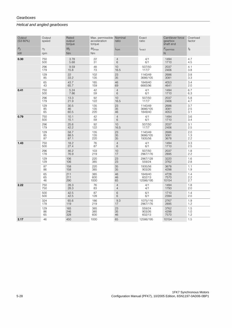
Gearboxes
Helical and angled gearboxes
1FK7 Synchronous Motors5-28 Configuration Manual (PFK7), 10/2005 Edition, 6SN1197-0AD06-0BP1
Output (S3 60%)
Output speed
Rated output torque
Max. permissible acceleration torque
Nominal ratio
Exact ratio
Cantilever force gearbox shaft end
Overload factor
P2 n2 M2 M2max inom iexact Frpermiss fBkW rpm Nm Nm N
0.30 750500
3.785.68
2231
46
4/16/1
14941710
4.74.5
296179
9.5915.8
4873
1016.5
507/50117/7
20372406
4.13.8
12985
2233.2
102135
2335
1140/493686/105
26863081
3.83.3
6543
43.765.7
185159
4669
1849/406665/96
40534641
3.42.0
0.41 750500
5.247.86
4259
46
4/16/1
14941710
6.76.3
296179
13.321.9
92122
1016.5
507/50117/7
20372406
5.84.7
1298565
30.54660.5
135135220
233546
1140/493686/1051849/40
268630814053
3.72.53.1
0.79 750500
10.115.1
4259
46
4/16/1
14941710
3.63.4
296179
25.642.2
92122
1016.5
507/50117/7
20372406
3.12.5
1298587
58.788.587.1
135135220
233535
1140/493686/1051935/56
268630813678
2.01.32.2
1.43 750500
18.227.4
7687
46
4/16/1
14941710
3.32.5
296178
46.276.9
103219
1017
507/502967/176
20372895
1.82.2
129129
106106
220385
2323
2967/128559/24
32203762
1.62.8
8786
158158
220385
3535
1935/56903/26
36784298
1.11.9
656546
211211290
385600
1000
464665
1849/40602/13
12586/195
47287570
10154
1.42.22.7
2.22 750750
28.328.3
7683
44
4/14/1
14941793
1.82.0
500500
42.542.5
87128
66
6/16/1
17102394
1.42.0
324178
65.6119
186219
9.317
1075/1162967/176
27672895
1.91.2
1298665
165246328
385385600
233546
559/24903/26602/13
376242987570
1.51.01.2
2.17 46 450 1000 65 12586/195 10154 1.5
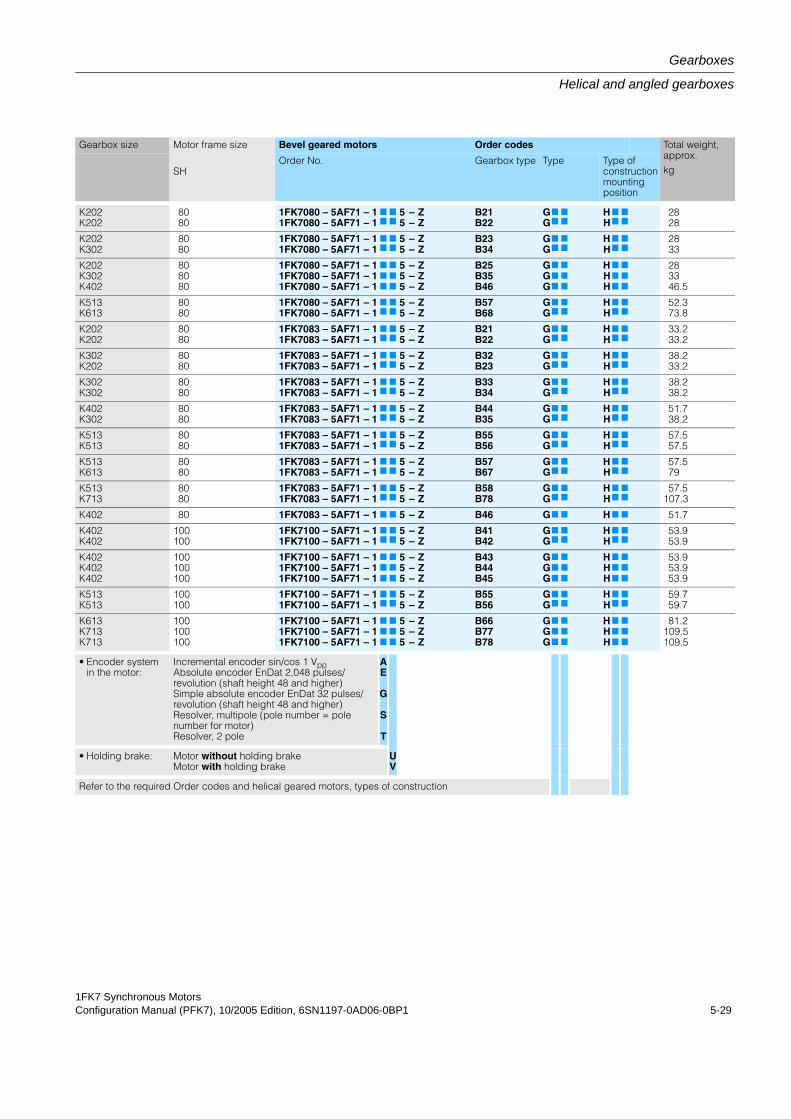
1FK7 Synchronous MotorsConfiguration Manual (PFK7), 10/2005 Edition, 6SN1197-0AD06-0BP1 5-29
Gearboxes
Helical and angled gearboxes
Gearbox size Motor frame size Bevel geared motors Order codes Total weight, approx.kgSH
Order No. Gearbox type Type Type of construction mounting position
K202K202
8080
1FK7080 – 5AF71 – 11FK7080 – 5AF71 – 1
7
7
7
7
55
––
ZZ
B21B22
GG7
7
7
7
HH7
7
7
7
2828
K202K302
8080
1FK7080 – 5AF71 – 11FK7080 – 5AF71 – 1
7
7
7
7
55
––
ZZ
B23B34
GG7
7
7
7
HH7
7
7
7
2833
K202K302K402
808080
1FK7080 – 5AF71 – 11FK7080 – 5AF71 – 11FK7080 – 5AF71 – 1
7
7
7
7
7
7
555
–––
ZZZ
B25B35B46
GGG
7
7
7
7
7
7
HHH
7
7
7
7
7
7
283346.5
K513K613
8080
1FK7080 – 5AF71 – 11FK7080 – 5AF71 – 1
7
7
7
7
55
––
ZZ
B57B68
GG7
7
7
7
HH7
7
7
7
52.373.8
K202K202
8080
1FK7083 – 5AF71 – 11FK7083 – 5AF71 – 1
7
7
7
7
55
––
ZZ
B21B22
GG7
7
7
7
HH7
7
7
7
33.233.2
K302K202
8080
1FK7083 – 5AF71 – 11FK7083 – 5AF71 – 1
7
7
7
7
55
––
ZZ
B32B23
GG7
7
7
7
HH7
7
7
7
38.233.2
K302K302
8080
1FK7083 – 5AF71 – 11FK7083 – 5AF71 – 1
7
7
7
7
55
––
ZZ
B33B34
GG7
7
7
7
HH7
7
7
7
38.238.2
K402K302
8080
1FK7083 – 5AF71 – 11FK7083 – 5AF71 – 1
7
7
7
7
55
––
ZZ
B44B35
GG7
7
7
7
HH7
7
7
7
51.738.2
K513K513
8080
1FK7083 – 5AF71 – 11FK7083 – 5AF71 – 1
7
7
7
7
55
––
ZZ
B55B56
GG7
7
7
7
HH7
7
7
7
57.557.5
K513K613
8080
1FK7083 – 5AF71 – 11FK7083 – 5AF71 – 1
7
7
7
7
55
––
ZZ
B57B67
GG7
7
7
7
HH7
7
7
7
57.579
K513K713
8080
1FK7083 – 5AF71 – 11FK7083 – 5AF71 – 1
7
7
7
7
55
––
ZZ
B58B78
GG7
7
7
7
HH7
7
7
7
57.5107.3
K402 80 1FK7083 – 5AF71 – 1 7 7 5 – Z B46 G7 7 H 7 7 51.7
K402K402
100100
1FK7100 – 5AF71 – 11FK7100 – 5AF71 – 1
7
7
7
7
55
––
ZZ
B41B42
GG7
7
7
7
HH7
7
7
7
53.953.9
K402K402K402
100100100
1FK7100 – 5AF71 – 11FK7100 – 5AF71 – 11FK7100 – 5AF71 – 1
7
7
7
7
7
7
555
–––
ZZZ
B43B44B45
GGG
7
7
7
7
7
7
HHH
7
7
7
7
7
7
53.953.953.9
K513K513
100100
1FK7100 – 5AF71 – 11FK7100 – 5AF71 – 1
7
7
7
7
55
––
ZZ
B55B56
GG7
7
7
7
HH7
7
7
7
59.759.7
K613K713K713
100100100
1FK7100 – 5AF71 – 11FK7100 – 5AF71 – 11FK7100 – 5AF71 – 1
7
7
7
7
7
7
555
–––
ZZZ
B66B77B78
GGG
7
7
7
7
7
7
HHH
7
7
7
7
7
7
81.2109.5109.5
• Encoder systemin the motor:
Incremental encoder sin/cos 1 VppAbsolute encoder EnDat 2,048 pulses/revolution (shaft height 48 and higher)Simple absolute encoder EnDat 32 pulses/revolution (shaft height 48 and higher)Resolver, multipole (pole number = pole number for motor)Resolver, 2 pole
AE
G
S
T
• Holding brake: Motor without holding brakeMotor with holding brake
UV
Refer to the required Order codes and helical geared motors, types of construction
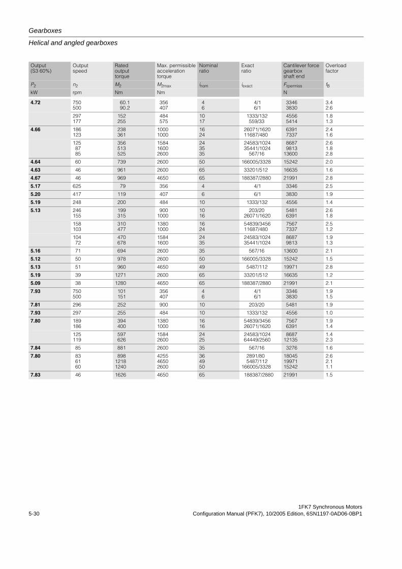
Gearboxes
Helical and angled gearboxes
1FK7 Synchronous Motors5-30 Configuration Manual (PFK7), 10/2005 Edition, 6SN1197-0AD06-0BP1
Output (S3 60%)
Output speed
Rated output torque
Max. permissible acceleration torque
Nominal ratio
Exact ratio
Cantilever force gearbox shaft end
Overload factor
P2 n2 M2 M2max inom iexact Frpermiss fBkW rpm Nm Nm N
4.72 750500
60.190.2
356407
46
4/16/1
33463830
3.42.6
297177
152255
484575
1017
1333/132559/33
45565414
1.81.3
4.66 186123
238361
10001000
1624
26071/162011687/480
63917337
2.41.6
1258785
356513525
158416002600
243535
24583/102435441/1024
567/16
86879813
13600
2.61.82.8
4.64 60 739 2600 50 166005/3328 15242 2.0
4.63 46 961 2600 65 33201/512 16635 1.6
4.67 46 969 4650 65 188387/2880 21991 2.8
5.17 625 79 356 4 4/1 3346 2.5
5.20 417 119 407 6 6/1 3830 1.9
5.19 248 200 484 10 1333/132 4556 1.4
5.13 246155
199315
9001000
1016
203/2026071/1620
54816391
2.61.8
158103
310477
13801000
1624
54839/345611687/480
75677337
2.51.2
10472
470678
15841600
2435
24583/102435441/1024
86879813
1.91.3
5.16 71 694 2600 35 567/16 13600 2.1
5.12 50 978 2600 50 166005/3328 15242 1.5
5.13 51 960 4650 49 5487/112 19971 2.8
5.19 39 1271 2600 65 33201/512 16635 1.2
5.09 38 1280 4650 65 188387/2880 21991 2.1
7.93 750500
101151
356407
46
4/16/1
33463830
1.91.5
7.81 296 252 900 10 203/20 5481 1.9
7.93 297 255 484 10 1333/132 4556 1.0
7.80 189186
394400
13801000
1616
54839/345626071/1620
75676391
1.91.4
125119
597626
15842600
2425
24583/102464449/2560
868712135
1.42.3
7.84 85 881 2600 35 567/16 3276 1.6
7.80 836160
89812181240
425546502600
364950
2891/805487/112
166005/3328
180451997115242
2.62.11.1
7.83 46 1626 4650 65 188387/2880 21991 1.5
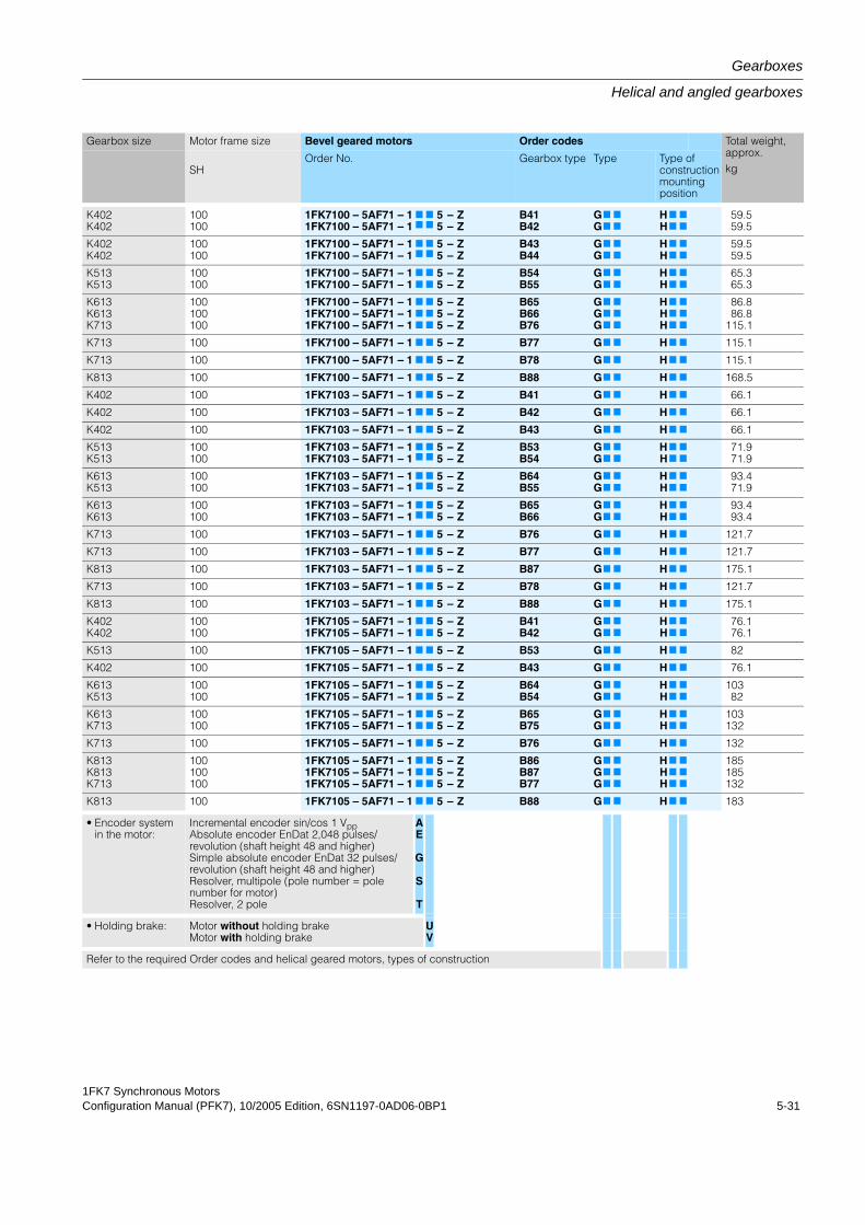
1FK7 Synchronous MotorsConfiguration Manual (PFK7), 10/2005 Edition, 6SN1197-0AD06-0BP1 5-31
Gearboxes
Helical and angled gearboxes
Gearbox size Motor frame size Bevel geared motors Order codes Total weight, approx.kgSH
Order No. Gearbox type Type Type of construction mounting position
K402K402
100100
1FK7100 – 5AF71 – 11FK7100 – 5AF71 – 1
7
7
7
7
55
––
ZZ
B41B42
GG7
7
7
7
HH7
7
7
7
59.559.5
K402K402
100100
1FK7100 – 5AF71 – 11FK7100 – 5AF71 – 1
7
7
7
7
55
––
ZZ
B43B44
GG7
7
7
7
HH7
7
7
7
59.559.5
K513K513
100100
1FK7100 – 5AF71 – 11FK7100 – 5AF71 – 1
7
7
7
7
55
––
ZZ
B54B55
GG7
7
7
7
HH7
7
7
7
65.365.3
K613K613K713
100100100
1FK7100 – 5AF71 – 11FK7100 – 5AF71 – 11FK7100 – 5AF71 – 1
7
7
7
7
7
7
555
–––
ZZZ
B65B66B76
GGG
7
7
7
7
7
7
HHH
7
7
7
7
7
7
86.886.8
115.1
K713 100 1FK7100 – 5AF71 – 1 7 7 5 – Z B77 G7 7 H 7 7 115.1
K713 100 1FK7100 – 5AF71 – 1 7 7 5 – Z B78 G7 7 H 7 7 115.1
K813 100 1FK7100 – 5AF71 – 1 7 7 5 – Z B88 G7 7 H 7 7 168.5
K402 100 1FK7103 – 5AF71 – 1 7 7 5 – Z B41 G7 7 H 7 7 66.1
K402 100 1FK7103 – 5AF71 – 1 7 7 5 – Z B42 G7 7 H 7 7 66.1
K402 100 1FK7103 – 5AF71 – 1 7 7 5 – Z B43 G7 7 H 7 7 66.1
K513K513
100100
1FK7103 – 5AF71 – 11FK7103 – 5AF71 – 1
7
7
7
7
55
––
ZZ
B53B54
GG7
7
7
7
HH7
7
7
7
71.971.9
K613K513
100100
1FK7103 – 5AF71 – 11FK7103 – 5AF71 – 1
7
7
7
7
55
––
ZZ
B64B55
GG7
7
7
7
HH7
7
7
7
93.471.9
K613K613
100100
1FK7103 – 5AF71 – 11FK7103 – 5AF71 – 1
7
7
7
7
55
––
ZZ
B65B66
GG7
7
7
7
HH7
7
7
7
93.493.4
K713 100 1FK7103 – 5AF71 – 1 7 7 5 – Z B76 G7 7 H 7 7 121.7
K713 100 1FK7103 – 5AF71 – 1 7 7 5 – Z B77 G7 7 H 7 7 121.7
K813 100 1FK7103 – 5AF71 – 1 7 7 5 – Z B87 G7 7 H 7 7 175.1
K713 100 1FK7103 – 5AF71 – 1 7 7 5 – Z B78 G7 7 H 7 7 121.7
K813 100 1FK7103 – 5AF71 – 1 7 7 5 – Z B88 G7 7 H 7 7 175.1
K402K402
100100
1FK7105 – 5AF71 – 11FK7105 – 5AF71 – 1
7
7
7
7
55
––
ZZ
B41B42
GG7
7
7
7
HH7
7
7
7
76.176.1
K513 100 1FK7105 – 5AF71 – 1 7 7 5 – Z B53 G7 7 H 7 7 82
K402 100 1FK7105 – 5AF71 – 1 7 7 5 – Z B43 G7 7 H 7 7 76.1
K613K513
100100
1FK7105 – 5AF71 – 11FK7105 – 5AF71 – 1
7
7
7
7
55
––
ZZ
B64B54
GG7
7
7
7
HH7
7
7
7
10382
K613K713
100100
1FK7105 – 5AF71 – 11FK7105 – 5AF71 – 1
7
7
7
7
55
––
ZZ
B65B75
GG7
7
7
7
HH7
7
7
7
103132
K713 100 1FK7105 – 5AF71 – 1 7 7 5 – Z B76 G7 7 H 7 7 132
K813K813K713
100100100
1FK7105 – 5AF71 – 11FK7105 – 5AF71 – 11FK7105 – 5AF71 – 1
7
7
7
7
7
7
555
–––
ZZZ
B86B87B77
GGG
7
7
7
7
7
7
HHH
7
7
7
7
7
7
185185132
K813 100 1FK7105 – 5AF71 – 1 7 7 5 – Z B88 G7 7 H 7 7 183
• Encoder systemin the motor:
Incremental encoder sin/cos 1 VppAbsolute encoder EnDat 2,048 pulses/revolution (shaft height 48 and higher)Simple absolute encoder EnDat 32 pulses/revolution (shaft height 48 and higher)Resolver, multipole (pole number = pole number for motor)Resolver, 2 pole
AE
G
S
T
• Holding brake: Motor without holding brakeMotor with holding brake
UV
Refer to the required Order codes and helical geared motors, types of construction
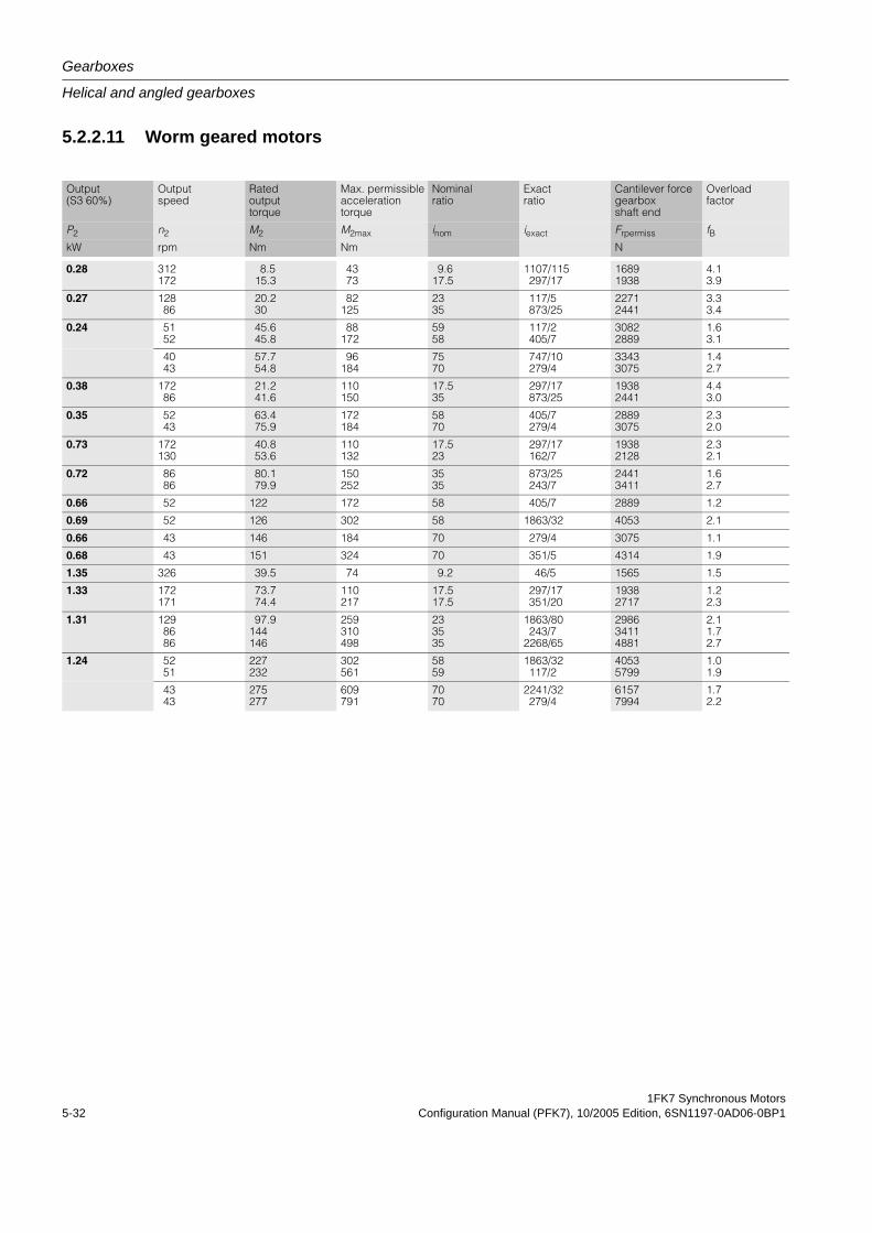
Gearboxes
Helical and angled gearboxes
1FK7 Synchronous Motors5-32 Configuration Manual (PFK7), 10/2005 Edition, 6SN1197-0AD06-0BP1
5.2.2.11 Worm geared motors
Output (S3 60%)
Output speed
Rated output torque
Max. permissible acceleration torque
Nominal ratio
Exact ratio
Cantilever force gearbox shaft end
Overload factor
P2 n2 M2 M2max inom iexact Frpermiss fBkW rpm Nm Nm N
0.28 312172
8.515.3
4373
9.617.5
1107/115297/17
16891938
4.13.9
0.27 12886
20.230
82125
2335
117/5873/25
22712441
3.33.4
0.24 5152
45.645.8
88172
5958
117/2405/7
30822889
1.63.1
4043
57.754.8
96184
7570
747/10279/4
33433075
1.42.7
0.38 17286
21.241.6
110150
17.535
297/17873/25
19382441
4.43.0
0.35 5243
63.475.9
172184
5870
405/7279/4
28893075
2.32.0
0.73 172130
40.853.6
110132
17.523
297/17162/7
19382128
2.32.1
0.72 8686
80.179.9
150252
3535
873/25243/7
24413411
1.62.7
0.66 52 122 172 58 405/7 2889 1.2
0.69 52 126 302 58 1863/32 4053 2.1
0.66 43 146 184 70 279/4 3075 1.1
0.68 43 151 324 70 351/5 4314 1.9
1.35 326 39.5 74 9.2 46/5 1565 1.5
1.33 172171
73.774.4
110217
17.517.5
297/17351/20
19382717
1.22.3
1.31 1298686
97.9144146
259310498
233535
1863/80243/7
2268/65
298634114881
2.11.72.7
1.24 5251
227232
302561
5859
1863/32117/2
40535799
1.01.9
4343
275277
609791
7070
2241/32279/4
61577994
1.72.2
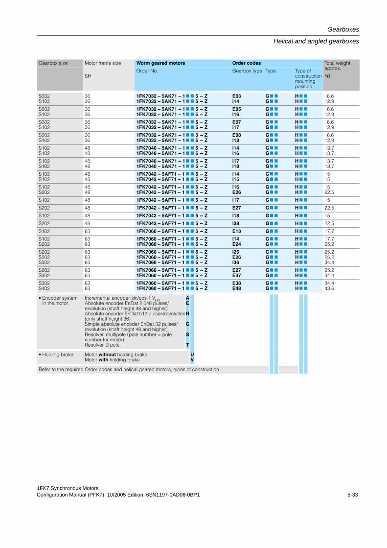
1FK7 Synchronous MotorsConfiguration Manual (PFK7), 10/2005 Edition, 6SN1197-0AD06-0BP1 5-33
Gearboxes
Helical and angled gearboxes
Gearbox size Motor frame size Worm geared motors Order codes Total weight, approx.kgSH
Order No. Gearbox type Type Type of construction mounting position
S002S102
3636
1FK7032 – 5AK71 – 11FK7032 – 5AK71 – 1
7
7
7
7
55
––
ZZ
E03I14
GG7
7
7
7
HH7
7
7
7
6.612.9
S002S102
3636
1FK7032 – 5AK71 – 11FK7032 – 5AK71 – 1
7
7
7
7
55
––
ZZ
E05I16
GG7
7
7
7
HH7
7
7
7
6.612.9
S002S102
3636
1FK7032 – 5AK71 – 11FK7032 – 5AK71 – 1
7
7
7
7
55
––
ZZ
E07I17
GG7
7
7
7
HH7
7
7
7
6.612.9
S002S102
3636
1FK7032 – 5AK71 – 11FK7032 – 5AK71 – 1
7
7
7
7
55
––
ZZ
E08I18
GG7
7
7
7
HH7
7
7
7
6.612.9
S102S102
4848
1FK7040 – 5AK71 – 11FK7040 – 5AK71 – 1
7
7
7
7
55
––
ZZ
I14I16
GG7
7
7
7
HH7
7
7
7
13.713.7
S102S102
4848
1FK7040 – 5AK71 – 11FK7040 – 5AK71 – 1
7
7
7
7
55
––
ZZ
I17I18
GG7
7
7
7
HH7
7
7
7
13.713.7
S102S102
4848
1FK7042 – 5AF71 – 11FK7042 – 5AF71 – 1
7
7
7
7
55
––
ZZ
I14I15
GG7
7
7
7
HH7
7
7
7
1515
S102S202
4848
1FK7042 – 5AF71 – 11FK7042 – 5AF71 – 1
7
7
7
7
55
––
ZZ
I16E26
GG7
7
7
7
HH7
7
7
7
1522.5
S102 48 1FK7042 – 5AF71 – 1 7 7 5 – Z I17 G7 7 H 7 7 15
S202 48 1FK7042 – 5AF71 – 1 7 7 5 – Z E27 G7 7 H 7 7 22.5
S102 48 1FK7042 – 5AF71 – 1 7 7 5 – Z I18 G7 7 H 7 7 15
S202 48 1FK7042 – 5AF71 – 1 7 7 5 – Z I28 G7 7 H 7 7 22.5
S102 63 1FK7060 – 5AF71 – 1 7 7 5 – Z E13 G7 7 H 7 7 17.7
S102S202
6363
1FK7060 – 5AF71 – 11FK7060 – 5AF71 – 1
7
7
7
7
55
––
ZZ
I14E24
GG7
7
7
7
HH7
7
7
7
17.725.2
S202S202S302
636363
1FK7060 – 5AF71 – 11FK7060 – 5AF71 – 11FK7060 – 5AF71 – 1
7
7
7
7
7
7
555
–––
ZZZ
I25E26I36
GGG
7
7
7
7
7
7
HHH
7
7
7
7
7
7
25.225.234.4
S202S302
6363
1FK7060 – 5AF71 – 11FK7060 – 5AF71 – 1
7
7
7
7
55
––
ZZ
E27E37
GG7
7
7
7
HH7
7
7
7
25.234.4
S302S402
6363
1FK7060 – 5AF71 – 11FK7060 – 5AF71 – 1
7
7
7
7
55
––
ZZ
E38E48
GG7
7
7
7
HH7
7
7
7
34.443.6
• Encoder systemin the motor:
Incremental encoder sin/cos 1 VppAbsolute encoder EnDat 2,048 pulses/revolution (shaft height 48 and higher)Absolute encoder EnDat 512 pulses/revolution(only shaft height 36)Simple absolute encoder EnDat 32 pulses/revolution (shaft height 48 and higher)Resolver, multipole (pole number = pole number for motor)Resolver, 2 pole
AE
H
G
S
T
• Holding brake: Motor without holding brakeMotor with holding brake
UV
Refer to the required Order codes and helical geared motors, types of construction
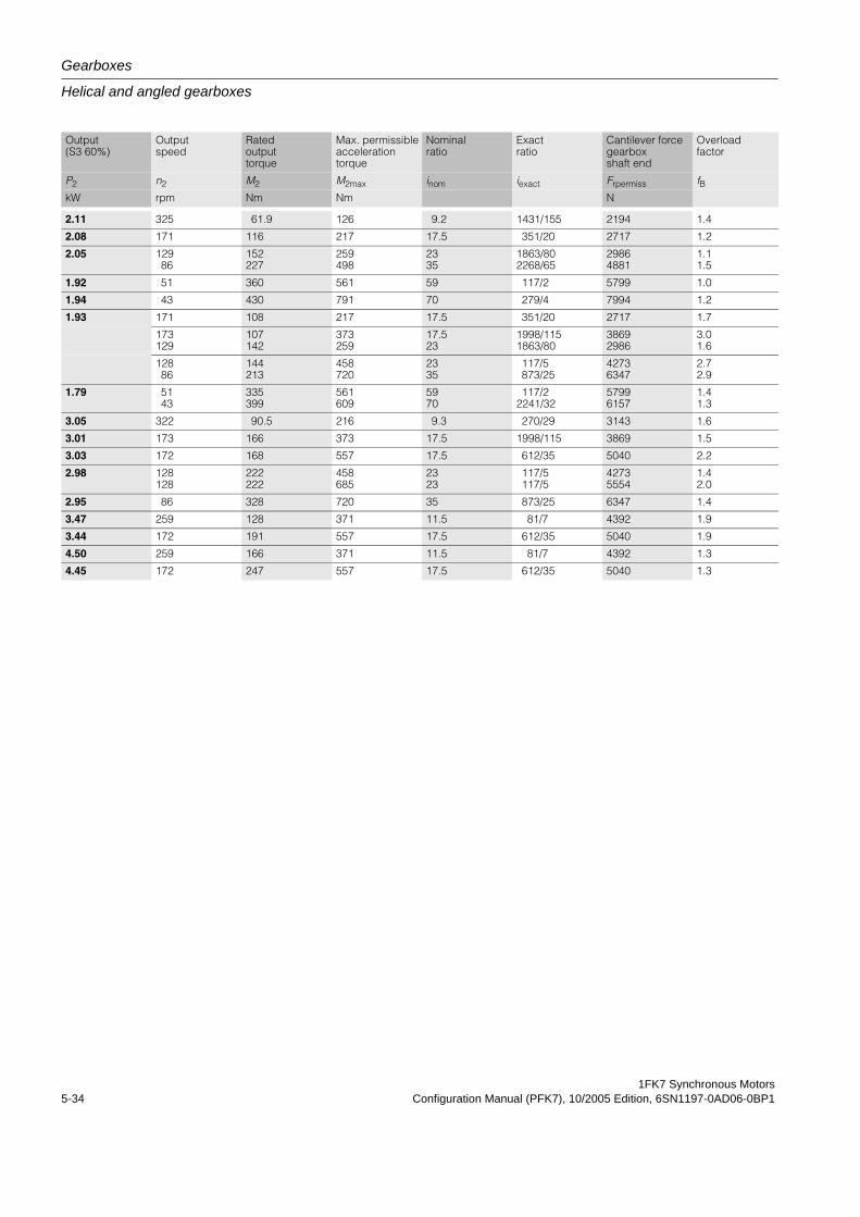
Gearboxes
Helical and angled gearboxes
1FK7 Synchronous Motors5-34 Configuration Manual (PFK7), 10/2005 Edition, 6SN1197-0AD06-0BP1
Output (S3 60%)
Output speed
Rated output torque
Max. permissible acceleration torque
Nominal ratio
Exact ratio
Cantilever force gearbox shaft end
Overload factor
P2 n2 M2 M2max inom iexact Frpermiss fBkW rpm Nm Nm N
2.11 325 61.9 126 9.2 1431/155 2194 1.4
2.08 171 116 217 17.5 351/20 2717 1.2
2.05 12986
152227
259498
2335
1863/802268/65
29864881
1.11.5
1.92 51 360 561 59 117/2 5799 1.0
1.94 43 430 791 70 279/4 7994 1.2
1.93 171 108 217 17.5 351/20 2717 1.7
173129
107142
373259
17.523
1998/1151863/80
38692986
3.01.6
12886
144213
458720
2335
117/5873/25
42736347
2.72.9
1.79 5143
335399
561609
5970
117/22241/32
57996157
1.41.3
3.05 322 90.5 216 9.3 270/29 3143 1.6
3.01 173 166 373 17.5 1998/115 3869 1.5
3.03 172 168 557 17.5 612/35 5040 2.2
2.98 128128
222222
458685
2323
117/5117/5
42735554
1.42.0
2.95 86 328 720 35 873/25 6347 1.4
3.47 259 128 371 11.5 81/7 4392 1.9
3.44 172 191 557 17.5 612/35 5040 1.9
4.50 259 166 371 11.5 81/7 4392 1.3
4.45 172 247 557 17.5 612/35 5040 1.3
1FK7 Synchronous MotorsConfiguration Manual (PFK7), 10/2005 Edition, 6SN1197-0AD06-0BP1 5-35
Gearbox
Planetary gearbox
Gearbox
5.3 Planetary gearbox
5.3.1 Motors with mounted planetary gearboxesThe gearboxes assigned to the individual motors as well as the gearbox ratios, available for these motor-gearbox combinations are listed in the selection tables of the motor-specific Sections. When making a selection, the maximum permissible input speed of the gearbox must be observed (this is the same as the maximum motor speed).
The motor-gearbox combinations, listed in the selection tables, are mainly intended for posi-tioning duty (S3). The manufacturer must be contacted if the motors are to be used in contin-uous duty at high speeds.
The 1FT and 1FK synchronous motors can be supplied ex factory (Siemens) complete with a planetary gearbox mounted through a flange.
5.3.2 Series SP+
5.3.2.1 Overview1FK7 motors can be combined with planetary gearboxes to form compact coaxial drive units. The gearboxes are flanged directly to the drive end of the motors.
When selecting gearboxes ensure that the maximum motor speed does not exceed the per-missible speed of the gearbox. In the case of high operating frequencies, allowance must be made for the withstand ratio f2.
The frictional losses of the gearbox must always be taken into account when engineering geared drives.
The gearboxes are only available in a non-balanced design.
Gearbox
Planetary gearbox
1FK7 Synchronous Motors5-36 Configuration Manual (PFK7), 10/2005 Edition, 6SN1197-0AD06-0BP1
5.3.2.2 Benefits• High efficiency:
> 97% single-stage> 94% 2-stage
• Minimum torsional play:<= 4 arcmin single-stage<= 6 arcmin 2-stage
• Power transmission from the central sun wheel to the planetary pinions
• No shaft deflections in the planetary pinions set due to the symmetrical force distribution
• Very low moment of inertia and hence short acceleration times of the motors
• Output shaft bearings dimensioned for high cantilever and axial loads with preloaded tapered-roller bearings
• The gearboxes are connected to the motor shaft via an integrated clamping hub. A plain motor shaft end is necessary for this purpose. Radial eccentricity tolerance N to DIN 42955 and vibration severity grade N to EN 60034-14 are sufficient. The motor flange is adapted via adapter plates.
• Output shaft of the gearbox exactly coaxial with the motor
• The gearboxes are sealed (seal between gear unit and motor) and filled with grease in the factory. They are lubricated for life and sealed. Gearboxes, frame sizes SP060S to SP 180S are suitable for all mounting positions.
• The quantity of oil in gearboxes, frame sizes SP210 and SP240 depends on the mounting position. The mounting position has to be specified when ordering.
• Gearbox degree of protection IP65 (IP64 for frame sizes SP 210 and SP 240)
• Small dimensions
• Low weight
1FK7 Synchronous MotorsConfiguration Manual (PFK7), 10/2005 Edition, 6SN1197-0AD06-0BP1 5-37
Gearbox
Planetary gearbox
5.3.2.3 IntegrationThe 1FK702 to 1FK710 motors are supplied ex factory (SIEMENS) complete with a plane-tary gearbox mounted through a flange.
The gearboxes assigned to the individual motors and gear ratios i available for these motor/gearbox combinations are listed in the selection table. When making a selection, the maxi-mum permissible input speed of the gearbox must be observed (this is the same as the maxi-mum motor speed).
The motor/gearbox combinations listed in the selection tables are mainly intended for cyclic operation S3 - 60 % (ON time ≤ 60 % and ≤20 min). Reduced maximum motor speeds and output torques apply for use in S1 continuous duty (ON time > 60 % or >20 min).
Gearbox temperatures may not exceed +90 °C, the maximum permissible input speed is limited from a time perspective.
It must be ensured that the geared motors have adequate cooling through convection. The gearbox must be able to dissipate sufficient heat through its flange.
Generally, planetary gearboxes can be used for ambient temperatures of between 0 ° and 40 °C. Temperatures down to -15 °C can be handled when special measures are applied (mechanical design measures, appropriate selection of lubricants etc.).
1FK7 synchronous motors to be implemented as follows for mounting to a gearbox:
• with plain shaft end
• Degree of protection IP65
• Anthracite paint finish
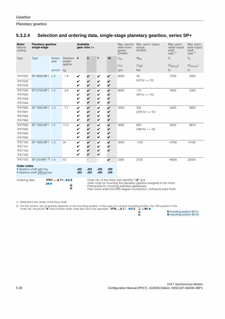
Gearbox
Planetary gearbox
1FK7 Synchronous Motors5-38 Configuration Manual (PFK7), 10/2005 Edition, 6SN1197-0AD06-0BP1
5.3.2.4 Selection and ordering data, single-stage planetary gearbox, series SP+
MotorNaturalcooling
Planetary gearbox single-stage
Available gear ratio i =
Max. permis-sible motor speedS3-60%
Max. perm. outputtorqueS3-60%
Max. perm.radial output shaftload 1)
Max. perm.axial output shaftload 1)
Type Type Rotary play
Gearbox-weight approx.
4 5 7 10 nG1
(n1)
MG2
(T2B)
Fr
(F2Rmax)
Fa
(F2Amax)
arcmin kg rpm Nm N N
1FK7022 SP 060S-MF1 ≤ 4 1.9 4 4 4 4 6000 40(32 for i = 10)
2700 2400
1FK70321FK7033
4
4
4
4
4
4
4
4
1FK70401FK70421FK70431FK7044
SP 075S-MF1 ≤ 4 3.9 4
4
4
4
4
4
4
4
4
4
4
4
4
4
4
4
6000 110(90 for i = 10)
4000 3350
1FK70601FK70611FK70631FK7064
SP 100S-MF1 ≤ 3 7.7 4
4
4
4
4
4
4
4
4
4
4
4
4
4
4
4
4500 300(225 for i = 10)
6300 5650
1FK70801FK70821FK70831FK7085
SP 140S-MF1 ≤ 3 17.2 4
4
4
4
4
4
4
4
4
4
4
4
4
4
4
4
4000 600(480 for i = 10)
9450 9870
1FK71001FK71011FK71031FK7105
SP 180S-MF1 ≤ 3 34 4
4
4
4
4
4
4
4
4
4
4
4
4
4
4–
3500 1100 14700 14150
1FK7105 SP 210-MF1 2) ≤ 4 53 – – – 4 2200 2720 18000 22500
Order codes• Gearbox shaft with key J02 J03 J05 J09• Gearbox shaft without key J22 J23 J25 J29
Ordering data 1FK7...-.A.71-..75-Z Order No. of the motor with identifier "-Z" andorder code for mounting the planetary gearbox assigned to the motorPrerequisite for mounting planetary gearboxes:Plain motor shaft end IP65 degree of protection, anthracite paint finish
J7 7GH
1) Referred to the center of the drive shaft.
2) For this version, the oil quantity depends on the mounting position. In the case of a vertical mounting position, the 12th position in the Order No. should be "9" and a further order code also has to be specified: 1FT6...-.A.79-.. 7 5-Z J.. + M1 7
GH
H mounting position IM V1G mounting position IM V3
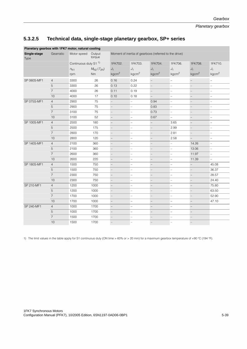
1FK7 Synchronous MotorsConfiguration Manual (PFK7), 10/2005 Edition, 6SN1197-0AD06-0BP1 5-39
Gearbox
Planetary gearbox
5.3.2.5 Technical data, single-stage planetary gearbox, SP+ series
Planetary gearbox with 1FK7 motor, natural cooling
Single-stageType
Gearratio Motor speed Output torque
Moment of inertia of gearboxs (referred to the drive)
Continuous duty S1 1) 1FK702. 1FK703. 1FK704. 1FK706. 1FK708. 1FK710.
nN1 MN2 (T2N) J1 J1 J1 J1 J1 J1
rpm Nm kgcm2 kgcm2 kgcm2 kgcm2 kgcm2 kgcm2
SP 060S-MF1 4 3300 26 0.16 0.24 – – – –
5 3300 26 0.13 0.22 – – – –
7 4000 26 0.11 0.19 – – – –
10 4000 17 0.10 0.18 – – – –
SP 075S-MF1 4 2900 75 – – 0.94 – – –
5 2900 75 – – 0.83 – – –
7 3100 75 – – 0.73 – – –
10 3100 52 – – 0.67 – – –
SP 100S-MF1 4 2500 180 – – – 3.65 – –
5 2500 175 – – – 2.99 – –
7 2800 170 – – – 2.81 – –
10 2800 120 – – – 2.58 – –
SP 140S-MF1 4 2100 360 – – – – 14.26 –
5 2100 360 – – – – 13.06 –
7 2600 360 – – – – 11.97 –
10 2600 220 – – – – 11.39 –
SP 180S-MF1 4 1500 750 – – – – – 45.08
5 1500 750 – – – – – 36.37
7 2300 750 – – – – – 28.57
10 2300 750 – – – – – 24.40
SP 210-MF1 4 1200 1000 – – – – – 75.80
5 1200 1000 – – – – – 63.50
7 1700 1000 – – – – – 52.90
10 1700 1000 – – – – – 47.10
SP 240-MF1 4 1000 1700 – – – – –
5 1000 1700 – – – – –
7 1500 1700 – – – – –
10 1500 1700 – – – – –
1) The limit values in the table apply for S1 continuous duty (ON time > 60% or > 20 min) for a maximum gearbox temperature of +90 °C (194 °F).
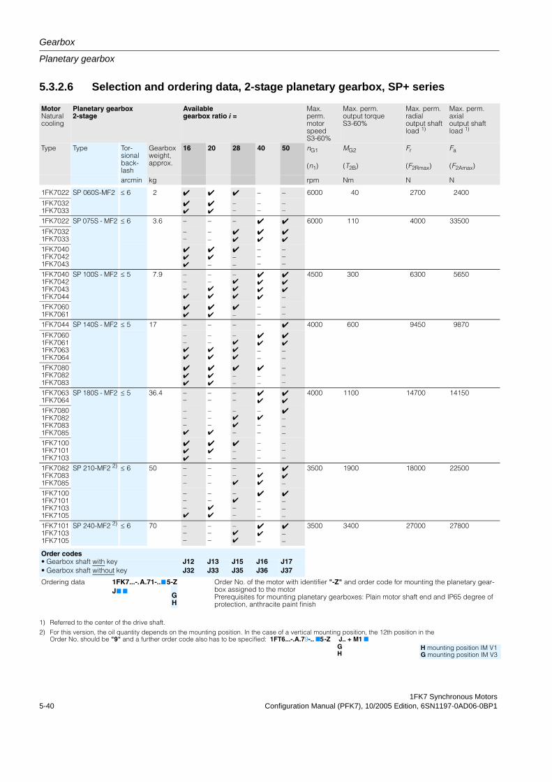
Gearbox
Planetary gearbox
1FK7 Synchronous Motors5-40 Configuration Manual (PFK7), 10/2005 Edition, 6SN1197-0AD06-0BP1
5.3.2.6 Selection and ordering data, 2-stage planetary gearbox, SP+ series
MotorNaturalcooling
Planetary gearbox 2-stage
Available gearbox ratio i =
Max. perm. motorspeed S3-60%
Max. perm. output torqueS3-60%
Max. perm.radial output shaftload 1)
Max. perm.axial output shaftload 1)
Type Type Tor-sional back-lash
Gearbox weight, approx.
16 20 28 40 50 nG1
(n1)
MG2
(T2B)
Fr
(F2Rmax)
Fa
(F2Amax)
arcmin kg rpm Nm N N
1FK7022 SP 060S-MF2 ≤ 6 2 4 4 4 – – 6000 40 2700 2400
1FK70321FK7033
44
44
––
––
––
1FK7022 SP 075S - MF2 ≤ 6 3.6 – – – 4 4 6000 110 4000 33500
1FK70321FK7033
––
––
44
44
44
1FK70401FK70421FK7043
444
44–
4––
–––
–––
1FK70401FK70421FK70431FK7044
SP 100S - MF2 ≤ 5 7.9 –––4
––44
–444
4444
444–
4500 300 6300 5650
1FK70601FK7061
44
44
4–
––
––
1FK7044 SP 140S - MF2 ≤ 5 17 – – – – 4 4000 600 9450 9870
1FK70601FK70611FK70631FK7064
––44
––44
–444
44––
44––
1FK70801FK70821FK7083
444
444
4––
4––
–––
1FK70631FK7064
SP 180S - MF2 ≤ 5 36.4 ––
––
––
44
44
4000 1100 14700 14150
1FK70801FK70821FK70831FK7085
–––4
–––4
–44–
–4––
4–––
1FK71001FK71011FK7103
444
44–
4––
–––
–––
1FK70821FK70831FK7085
SP 210-MF2 2) ≤ 6 50 –––
–––
––4
–44
44–
3500 1900 18000 22500
1FK71001FK71011FK71031FK7105
–––4
––44
–4––
4–––
4–––
1FK71011FK71031FK7105
SP 240-MF2 2) ≤ 6 70 –––
–––
–44
44–
4––
3500 3400 27000 27800
Order codes• Gearbox shaft with key J12 J13 J15 J16 J17• Gearbox shaft without key J32 J33 J35 J36 J37
Ordering data 1FK7...-.A.71-..75-Z Order No. of the motor with identifier "-Z" and order code for mounting the planetary gear-box assigned to the motorPrerequisites for mounting planetary gearboxes: Plain motor shaft end and IP65 degree of protection, anthracite paint finish
J7 7GH
1) Referred to the center of the drive shaft.
2) For this version, the oil quantity depends on the mounting position. In the case of a vertical mounting position, the 12th position in the Order No. should be "9" and a further order code also has to be specified: 1FT6...-.A.79-.. 75-Z J.. + M1 7
GH
H mounting position IM V1G mounting position IM V3
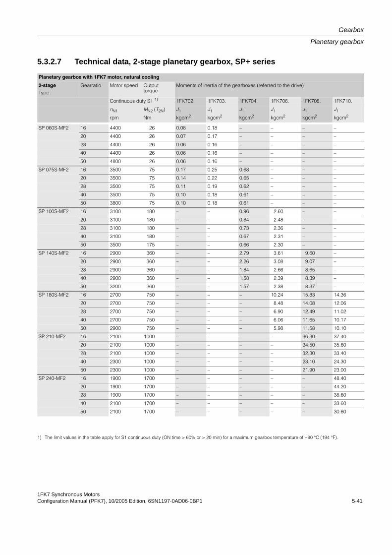
1FK7 Synchronous MotorsConfiguration Manual (PFK7), 10/2005 Edition, 6SN1197-0AD06-0BP1 5-41
Gearbox
Planetary gearbox
5.3.2.7 Technical data, 2-stage planetary gearbox, SP+ series
Planetary gearbox with 1FK7 motor, natural cooling
2-stageType
Gearratio Motor speed Output torque
Moments of inertia of the gearboxes (referred to the drive)
Continuous duty S1 1) 1FK702. 1FK703. 1FK704. 1FK706. 1FK708. 1FK710.
nN1 MN2 (T2N) J1 J1 J1 J1 J1 J1
rpm Nm kgcm2 kgcm2 kgcm2 kgcm2 kgcm2 kgcm2
SP 060S-MF2 16 4400 26 0.08 0.18 – – – –
20 4400 26 0.07 0.17 – – – –
28 4400 26 0.06 0.16 – – – –
40 4400 26 0.06 0.16 – – – –
50 4800 26 0.06 0.16 – – – –
SP 075S-MF2 16 3500 75 0.17 0.25 0.68 – – –
20 3500 75 0.14 0.22 0.65 – – –
28 3500 75 0.11 0.19 0.62 – – –
40 3500 75 0.10 0.18 0.61 – – –
50 3800 75 0.10 0.18 0.61 – – –
SP 100S-MF2 16 3100 180 – – 0.96 2.60 – –
20 3100 180 – – 0.84 2.48 – –
28 3100 180 – – 0.73 2.36 – –
40 3100 180 – – 0.67 2.31 – –
50 3500 175 – – 0.66 2.30 – –
SP 140S-MF2 16 2900 360 – – 2.79 3.61 9.60 –
20 2900 360 – – 2.26 3.08 9.07 –
28 2900 360 – – 1.84 2.66 8.65 –
40 2900 360 – – 1.58 2.39 8.39 –
50 3200 360 – – 1.57 2.38 8.37 –
SP 180S-MF2 16 2700 750 – – – 10.24 15.83 14.36
20 2700 750 – – – 8.48 14.08 12.06
28 2700 750 – – – 6.90 12.49 11.02
40 2700 750 – – – 6.06 11.65 10.17
50 2900 750 – – – 5.98 11.58 10.10
SP 210-MF2 16 2100 1000 – – – – 36.30 37.40
20 2100 1000 – – – – 34.50 35.60
28 2100 1000 – – – – 32.30 33.40
40 2300 1000 – – – – 23.10 24.30
50 2300 1000 – – – – 21.90 23.00
SP 240-MF2 16 1900 1700 – – – – – 48.40
20 1900 1700 – – – – – 44.20
28 1900 1700 – – – – – 38.60
40 2100 1700 – – – – – 33.60
50 2100 1700 – – – – – 30.60
1) The limit values in the table apply for S1 continuous duty (ON time > 60% or > 20 min) for a maximum gearbox temperature of +90 °C (194 °F).
Gearbox
Planetary gearbox
1FK7 Synchronous Motors5-42 Configuration Manual (PFK7), 10/2005 Edition, 6SN1197-0AD06-0BP1
5.3.3 LP+ series
5.3.3.1 Overview1FK7 motors can be combined with planetary gearboxes to form compact coaxial drive units. The gearboxes are flanged directly to the drive end of the motors.
When selecting the gearboxes, ensure that the permissible speed of the gearbox is not exceeded by the maximum speed of the motor. For high operating frequencies an allowance factor f2 must be taken into account, refer to Configuration Manual "General Section for Synchronous Motors". The frictional losses of the gearbox must always be taken into account when engineering geared drives.
The gearboxes are only available in a non-balanced design and with key.
5.3.3.2 Benefits• High efficiency, single-stage: > 97 %
• Torsional backlash, single-stage: ≤ 12 arcmin
• Power transmission from the central sun wheel to the planetary pinions
• No shaft deflections in the planetary gear set due to the symmetrical force distribution
• The gearboxes are connected to the motor shaft via an integrated clamping hub. A plain motor shaft end is required for this, while radial eccentricity tolerance N to DIN 42955 and vibration severity grade N to EN60034-14 are sufficient. The motor flange is adapted via adapter plates.
• Output shaft of gearbox exactly coaxial with the motor
• The gearboxes can be mounted in any position
• The gearboxes are sealed (seal between gearbox and motor) and filled with grease in the factory. They are lubricated and sealed for their service life.
• Gear unit degree of protection IP64
• Small dimensions
• Low weight
1FK7 Synchronous MotorsConfiguration Manual (PFK7), 10/2005 Edition, 6SN1197-0AD06-0BP1 5-43
Gearbox
Planetary gearbox
5.3.3.3 Integration1FK702 to 1FK710 synchronous motors are supplied ex factor (SIEMENS) complete with planetary gearbox mounted through a flange.
The gearboxes assigned to the individual motors as well as the gearbox ratios, available for these motor-gearbox combinations are listed in the Selection and ordering data table. When making a selection, the maximum permissible input speed of the gearbox must be observed (this is the same as the maximum motor speed).
The motor/gearbox combinations listed in the selection tables are mainly intended for cycle operation S3 - 60 % (ON time ≤ 60 % and ≤ 20 min). Reduced maximum motor speeds and output torques apply for use in S1 continuous duty (ON time > 60 % or > 20 min).
The gearbox temperature may not exceed 90 °C and the maximum permissible input speed is limited from a time perspective.
It must be ensured that the geared motors have adequate cooling through convection. The gearbox must be able to dissipate sufficient heat through its flange.
Generally, planetary gearboxes can be used for ambient temperatures of between 0 ° and 40 °C. Temperatures down to -15 °C can be handled when special measures are applied (mechanical design measures, appropriate selection of lubricants etc.).
1FK7 synchronous motors to be implemented as follows for mounting to a gearbox:
• with plain motor shaft end
• Radial eccentricity tolerance N
• Degree of protection IP64
• Anthracite paint finish
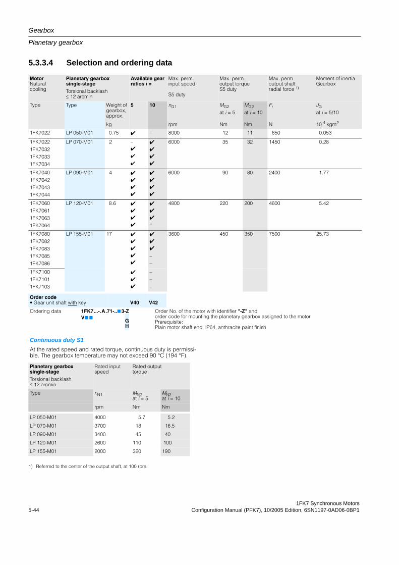
Gearbox
Planetary gearbox
1FK7 Synchronous Motors5-44 Configuration Manual (PFK7), 10/2005 Edition, 6SN1197-0AD06-0BP1
5.3.3.4 Selection and ordering data
MotorNaturalcooling
Planetary gearbox single-stageTorsional backlash ≤ 12 arcmin
Available gear ratios i =
Max. perm. input speed
S5 duty
Max. perm. output torque S5 duty
Max. perm.output shaft radial force 1)
Moment of inertiaGearbox
Type Type Weight of gearbox, approx.
5 10 nG1 MG2
at i = 5MG2
at i = 10Fr JG
at i = 5/10
kg rpm Nm Nm N 10-4 kgm2
1FK7022 LP 050-M01 0.75 4 – 8000 12 11 650 0.053
1FK70221FK70321FK70331FK7034
LP 070-M01 2 –4
4
4
4
4
4
4
6000 35 32 1450 0.28
1FK70401FK70421FK70431FK7044
LP 090-M01 4 4
4
4
4
4
4
4
4
6000 90 80 2400 1.77
1FK70601FK70611FK70631FK7064
LP 120-M01 8.6 4
4
4
4
4
4
4–
4800 220 200 4600 5.42
1FK70801FK70821FK70831FK70851FK7086
LP 155-M01 17 4
4
4
4
4
4
4
4
––
3600 450 350 7500 25.73
1FK71001FK71011FK7103
4
4
4
–––
Order code• Gear unit shaft with key V40 V42
Ordering data 1FK7...-.A.71-..7 3-Z Order No. of the motor with identifier "-Z" andorder code for mounting the planetary gearbox assigned to the motorPrerequisite:Plain motor shaft end, IP64, anthracite paint finish
V7 7GH
Continuous duty S1At the rated speed and rated torque, continuous duty is permissi-ble. The gearbox temperature may not exceed 90 °C (194 °F).
Planetary gearbox single-stageTorsional backlash ≤ 12 arcmin
Rated input speed
Rated outputtorque
Type nN1 MN2at i = 5
MN2at i = 10
rpm Nm Nm
LP 050-M01 4000 5.7 5.2
LP 070-M01 3700 18 16.5
LP 090-M01 3400 45 40
LP 120-M01 2600 110 100
LP 155-M01 2000 320 190
1) Referred to the center of the output shaft, at 100 rpm.
1FK7 Synchronous MotorsConfiguration Manual (PFK7), 10/2005 Edition, 6SN1197-0AD06-0BP1 6-1
Dimension Drawings 6Table 6-1: Introduction
NoteUsing a configuration interface that is very easy to understand, CAD CREATOR allows you to quickly find motor-specific
- dimension drawings
- 2D/3D CAD data
and supports you when generating plant/system documentation regarding project-specific information and parts lists.
Internet: www.siemens.com/cad-creator
NoteSiemens AG reserves the right to change the dimensions of the motors as part of mechanical design improvements without prior notice. This means that dimensions drawings can go out-of-date. Up-to-date dimension drawings can be requested at no charge from your local SIEMENS sales department.
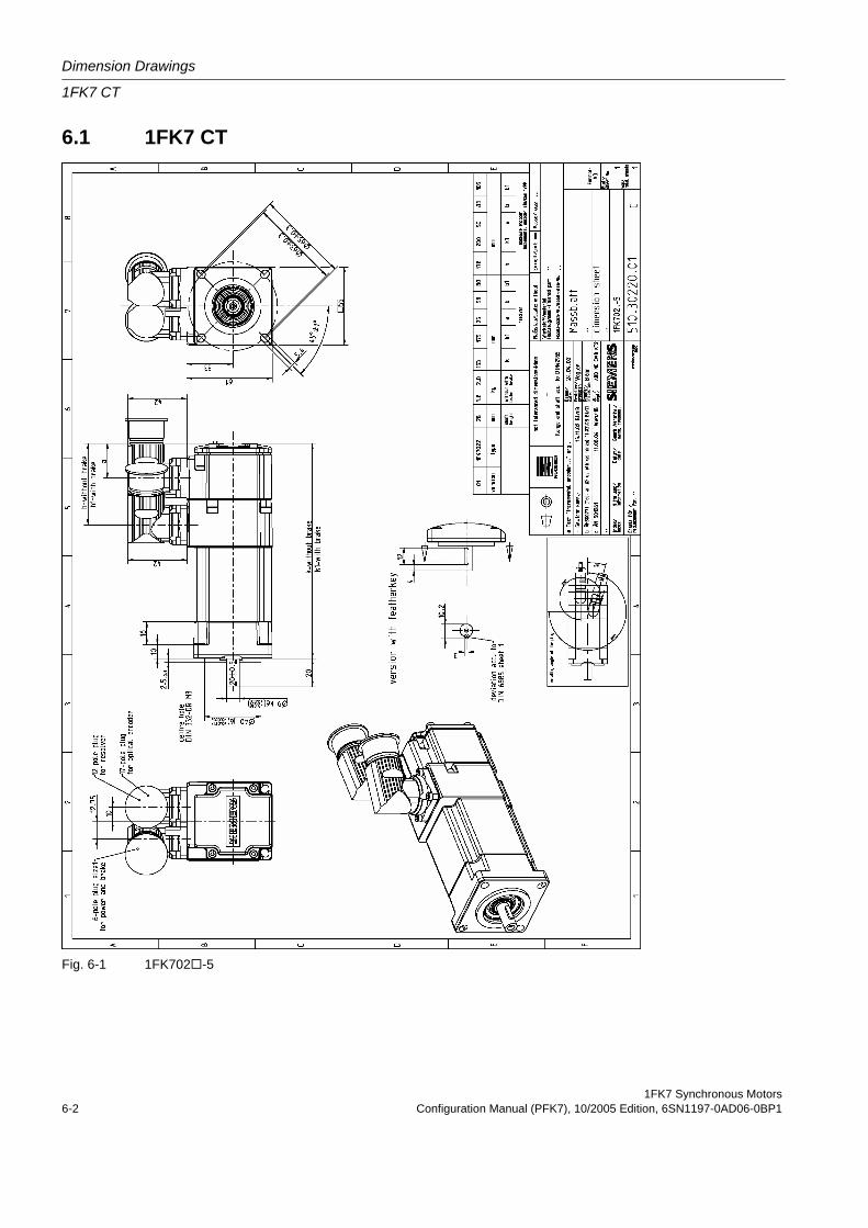
Dimension Drawings
1FK7 CT
1FK7 Synchronous Motors6-2 Configuration Manual (PFK7), 10/2005 Edition, 6SN1197-0AD06-0BP1
6.1 1FK7 CT
Fig. 6-1 1FK702 -5
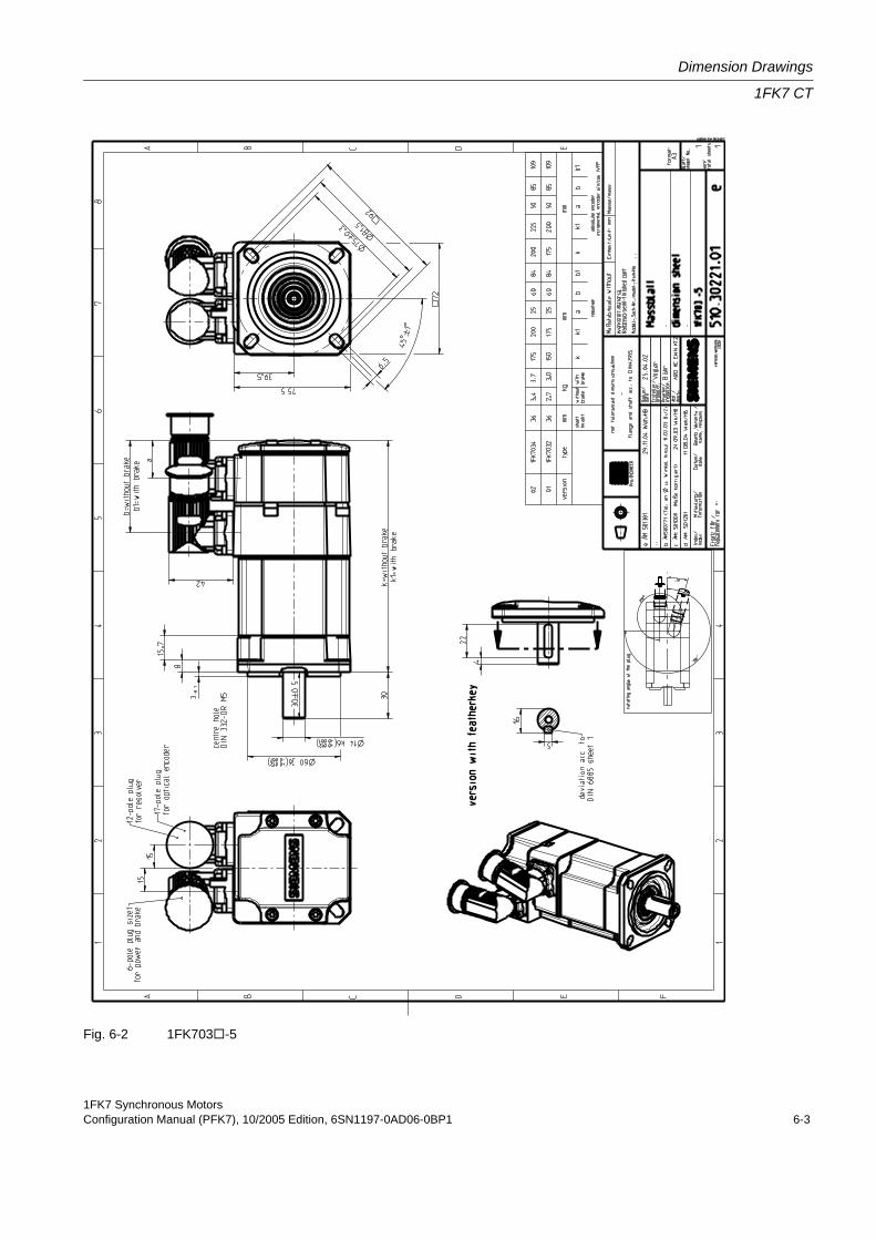
1FK7 Synchronous MotorsConfiguration Manual (PFK7), 10/2005 Edition, 6SN1197-0AD06-0BP1 6-3
Dimension Drawings
1FK7 CT
Fig. 6-2 1FK703 -5
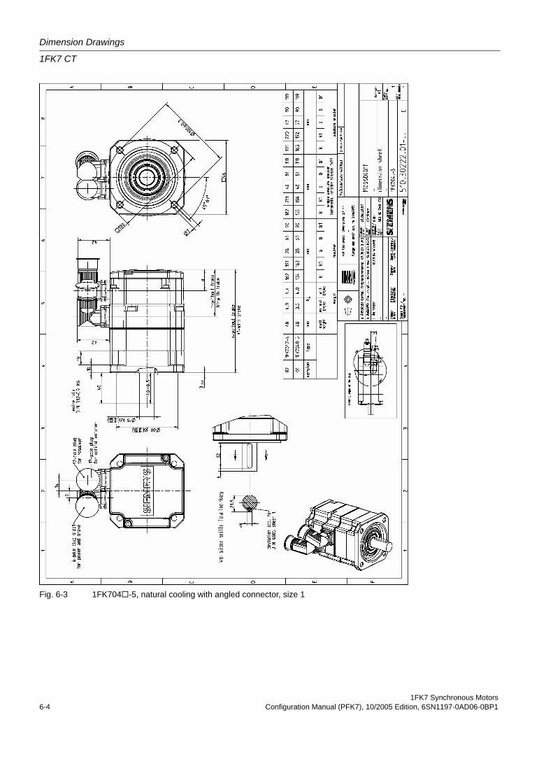
Dimension Drawings
1FK7 CT
1FK7 Synchronous Motors6-4 Configuration Manual (PFK7), 10/2005 Edition, 6SN1197-0AD06-0BP1
Fig. 6-3 1FK704 -5, natural cooling with angled connector, size 1
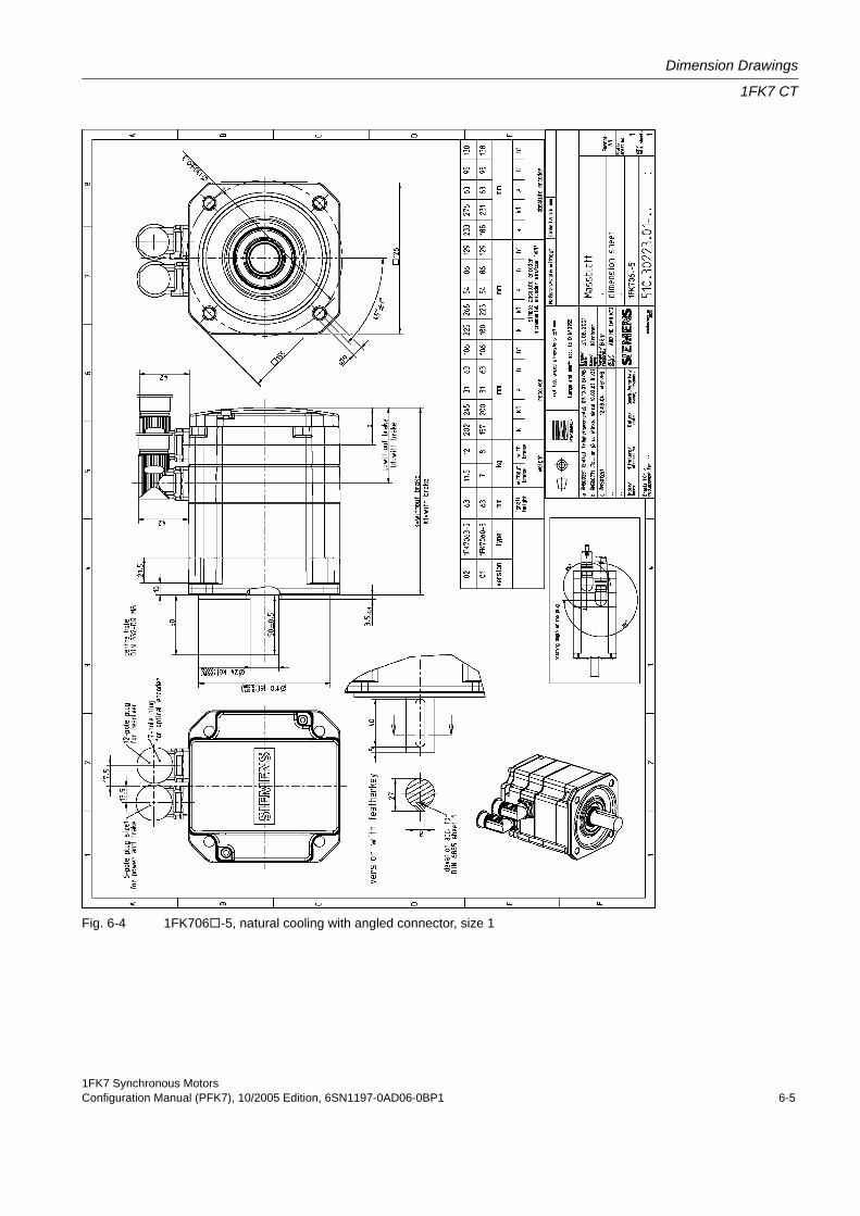
1FK7 Synchronous MotorsConfiguration Manual (PFK7), 10/2005 Edition, 6SN1197-0AD06-0BP1 6-5
Dimension Drawings
1FK7 CT
Fig. 6-4 1FK706 -5, natural cooling with angled connector, size 1
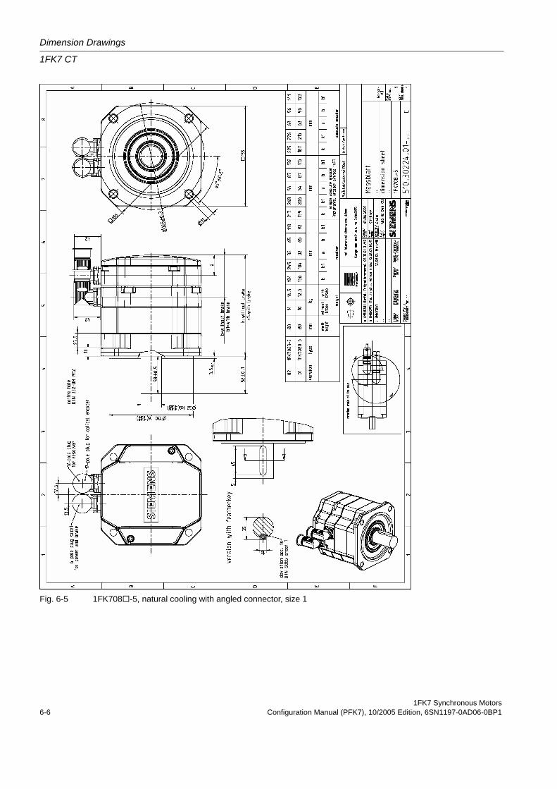
Dimension Drawings
1FK7 CT
1FK7 Synchronous Motors6-6 Configuration Manual (PFK7), 10/2005 Edition, 6SN1197-0AD06-0BP1
Fig. 6-5 1FK708 -5, natural cooling with angled connector, size 1
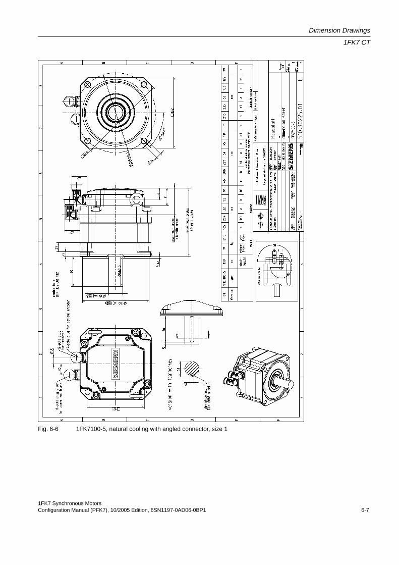
1FK7 Synchronous MotorsConfiguration Manual (PFK7), 10/2005 Edition, 6SN1197-0AD06-0BP1 6-7
Dimension Drawings
1FK7 CT
Fig. 6-6 1FK7100-5, natural cooling with angled connector, size 1
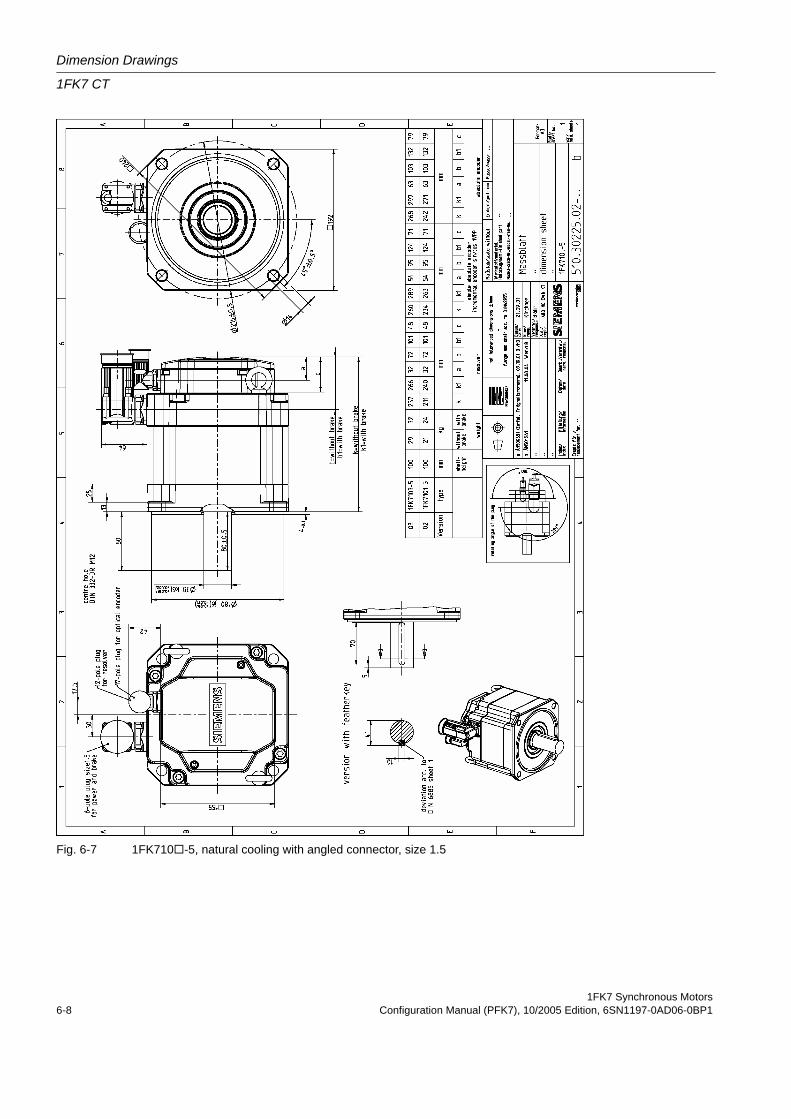
Dimension Drawings
1FK7 CT
1FK7 Synchronous Motors6-8 Configuration Manual (PFK7), 10/2005 Edition, 6SN1197-0AD06-0BP1
Fig. 6-7 1FK710 -5, natural cooling with angled connector, size 1.5
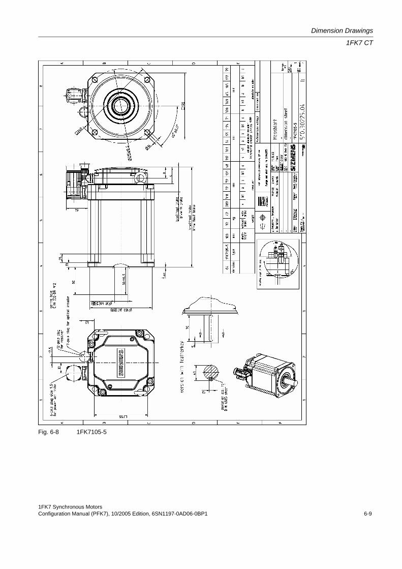
1FK7 Synchronous MotorsConfiguration Manual (PFK7), 10/2005 Edition, 6SN1197-0AD06-0BP1 6-9
Dimension Drawings
1FK7 CT
Fig. 6-8 1FK7105-5
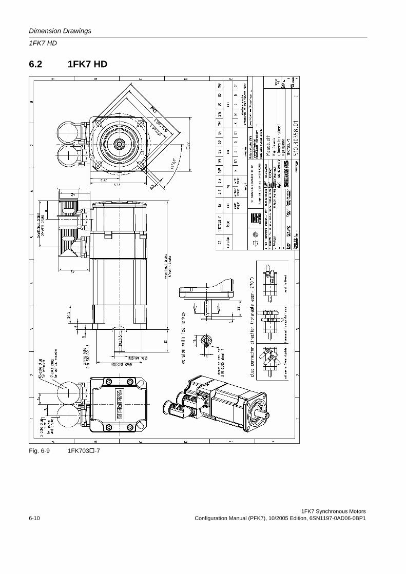
Dimension Drawings
1FK7 HD
1FK7 Synchronous Motors6-10 Configuration Manual (PFK7), 10/2005 Edition, 6SN1197-0AD06-0BP1
6.2 1FK7 HD
Fig. 6-9 1FK703 -7
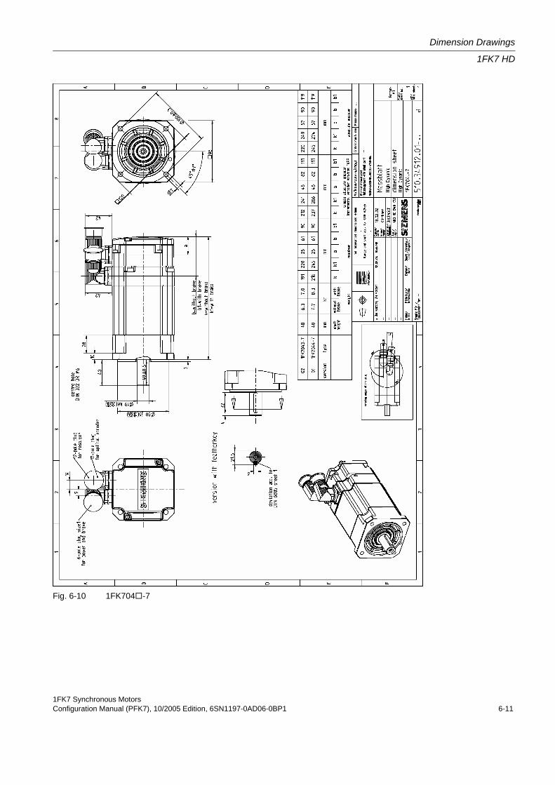
1FK7 Synchronous MotorsConfiguration Manual (PFK7), 10/2005 Edition, 6SN1197-0AD06-0BP1 6-11
Dimension Drawings
1FK7 HD
Fig. 6-10 1FK704 -7
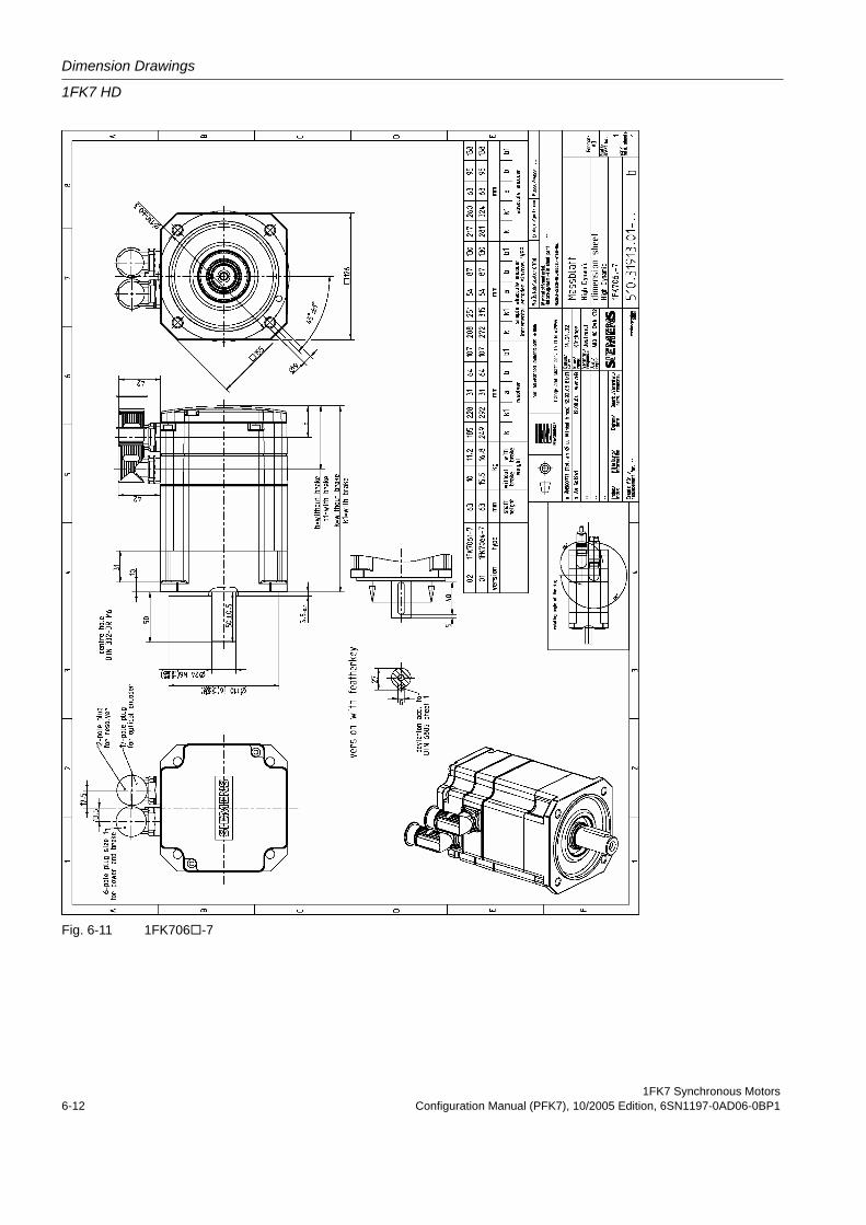
Dimension Drawings
1FK7 HD
1FK7 Synchronous Motors6-12 Configuration Manual (PFK7), 10/2005 Edition, 6SN1197-0AD06-0BP1
Fig. 6-11 1FK706 -7
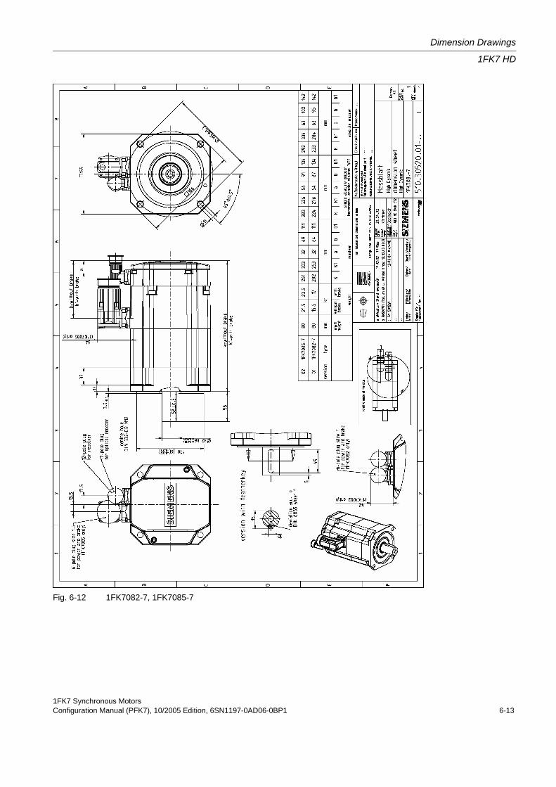
1FK7 Synchronous MotorsConfiguration Manual (PFK7), 10/2005 Edition, 6SN1197-0AD06-0BP1 6-13
Dimension Drawings
1FK7 HD
Fig. 6-12 1FK7082-7, 1FK7085-7
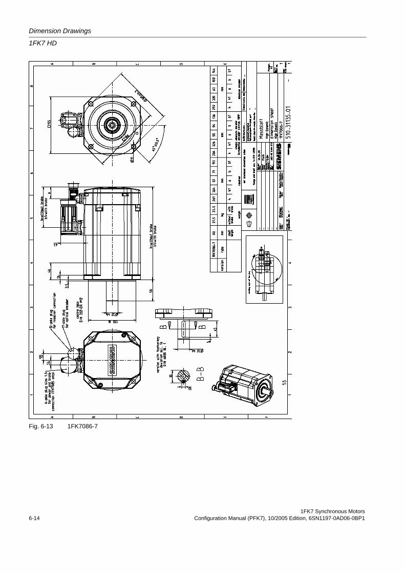
Dimension Drawings
1FK7 HD
1FK7 Synchronous Motors6-14 Configuration Manual (PFK7), 10/2005 Edition, 6SN1197-0AD06-0BP1
Fig. 6-13 1FK7086-7
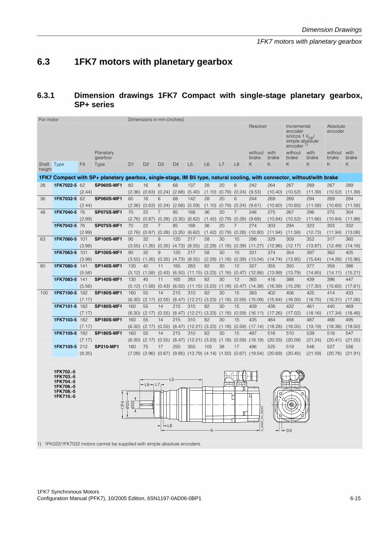
1FK7 Synchronous MotorsConfiguration Manual (PFK7), 10/2005 Edition, 6SN1197-0AD06-0BP1 6-15
Dimension Drawings
1FK7 motors with planetary gearbox
6.3 1FK7 motors with planetary gearbox
6.3.1 Dimension drawings 1FK7 Compact with single-stage planetary gearbox,SP+ series
For motor Dimensions in mm (inches)Resolver Incremental
encoder sin/cos 1 Vpp/simple absolute encoder 1)
Absolute encoder
Planetary gearbox
without brake
with brake
without brake
with brake
without brake
with brake
Shaft height
Type F4 Type D1 D2 D3 D4 L5 L6 L7 L8 K K K K K K
1FK7 Compact with SP+ planetary gearbox, single-stage, IM B5 type, natural cooling, with connector, without/with brake 28 1FK7022-5 62 SP060S-MF1 60 16 6 68 137 28 20 6 242 264 267 289 267 289
(2.44) (2.36) (0.63) (0.24) (2.68) (5.40) (1.10) (0.79) (0.24) (9.53) (10.40) (10.52) (11.39) (10.52) (11.39) 36 1FK7032-5 62 SP060S-MF1 60 16 6 68 142 28 20 6 244 269 269 294 269 294
(2.44) (2.36) (0.63) (0.24) (2.68) (5.59) (1.10) (0.79) (0.24) (9.61) (10.60) (10.60) (11.58) (10.60) (11.58) 48 1FK7040-5 76 SP075S-MF1 70 22 7 85 168 36 20 7 246 275 267 296 275 304
(2.99) (2.76) (0.87) (0.28) (3.35) (6.62) (1.42) (0.79) (0.28) (9.69) (10.84) (10.52) (11.66) (10.84) (11.98)1FK7042-5 76 SP075S-MF1 70 22 7 85 168 36 20 7 274 303 294 323 303 332
(2.99) (2.76) (0.87) (0.28) (3.35) (6.62) (1.42) (0.79) (0.28) (10.80) (11.94) (11.58) (12.73) (11.94) (13.08) 63 1FK7060-5 101 SP100S-MF1 90 32 9 120 217 58 30 10 286 329 309 352 317 360
(3.98) (3.55) (1.26) (0.35) (4.73) (8.55) (2.29) (1.18) (0.39) (11.27) (12.96) (12.17) (13.87) (12.49) (14.18)1FK7063-5 101 SP100S-MF1 90 32 9 120 217 58 30 10 331 374 354 397 362 405
(3.98) (3.55) (1.26) (0.35) (4.73) (8.55) (2.29) (1.18) (0.39) (13.04) (14.74) (13.95) (15.64) (14.26) (15.96) 80 1FK7080-5 141 SP140S-MF1 130 40 11 165 283 82 30 12 327 355 350 377 358 386
(5.56) (5.12) (1.58) (0.43) (6.50) (11.15) (3.23) (1.18) (0.47) (12.88) (13.99) (13.79) (14.85) (14.11) (15.21)1FK7083-5 141 SP140S-MF1 130 40 11 165 283 82 30 12 365 416 388 439 396 447
(5.56) (5.12) (1.58) (0.43) (6.50) (11.15) (3.23) (1.18) (0.47) (14.38) (16.39) (15.29) (17.30) (15.60) (17.61) 100 1FK7100-5 182 SP180S-MF1 160 55 14 215 310 82 30 15 383 402 406 425 414 433
(7.17) (6.30) (2.17) (0.55) (8.47) (12.21) (3.23) (1.18) (0.59) (15.09) (15.84) (16.00) (16.75) (16.31) (17.06)1FK7101-5 182 SP180S-MF1 160 55 14 215 310 82 30 15 409 438 432 461 440 469
(7.17) (6.30) (2.17) (0.55) (8.47) (12.21) (3.23) (1.18) (0.59) (16.11) (17.26) (17.02) (18.16) (17.34) (18.48)1FK7103-5 182 SP180S-MF1 160 55 14 215 310 82 30 15 435 464 458 487 466 495
(7.17) (6.30) (2.17) (0.55) (8.47) (12.21) (3.23) (1.18) (0.59) (17.14) (18.28) (18.05) (19.19) (18.36) (19.50)1FK7105-5 182 SP180S-MF1 160 55 14 215 310 82 30 15 487 516 510 539 518 547
(7.17) (6.30) (2.17) (0.55) (8.47) (12.21) (3.23) (1.18) (0.59) (19.19) (20.33) (20.09) (21.24) (20.41) (21.55)1FK7105-5 212 SP210-MF1 180 75 17 250 350 105 38 17 496 525 519 548 527 556
(8.35) (7.09) (2.96) (0.67) (9.85) (13.79) (4.14) (1.50) (0.67) (19.54) (20.69) (20.45) (21.59) (20.76) (21.91)
1FK702.-51FK703.-51FK704.-51FK706.-51FK708.-51FK710.-5
1) 1FK022/1FK7032 motors cannot be supplied with simple absolute encoders.
L6L5
L7
G_D
A65
_XX
_002
43
D3
D4
KL8
D2
D1
Ø Ø
F4
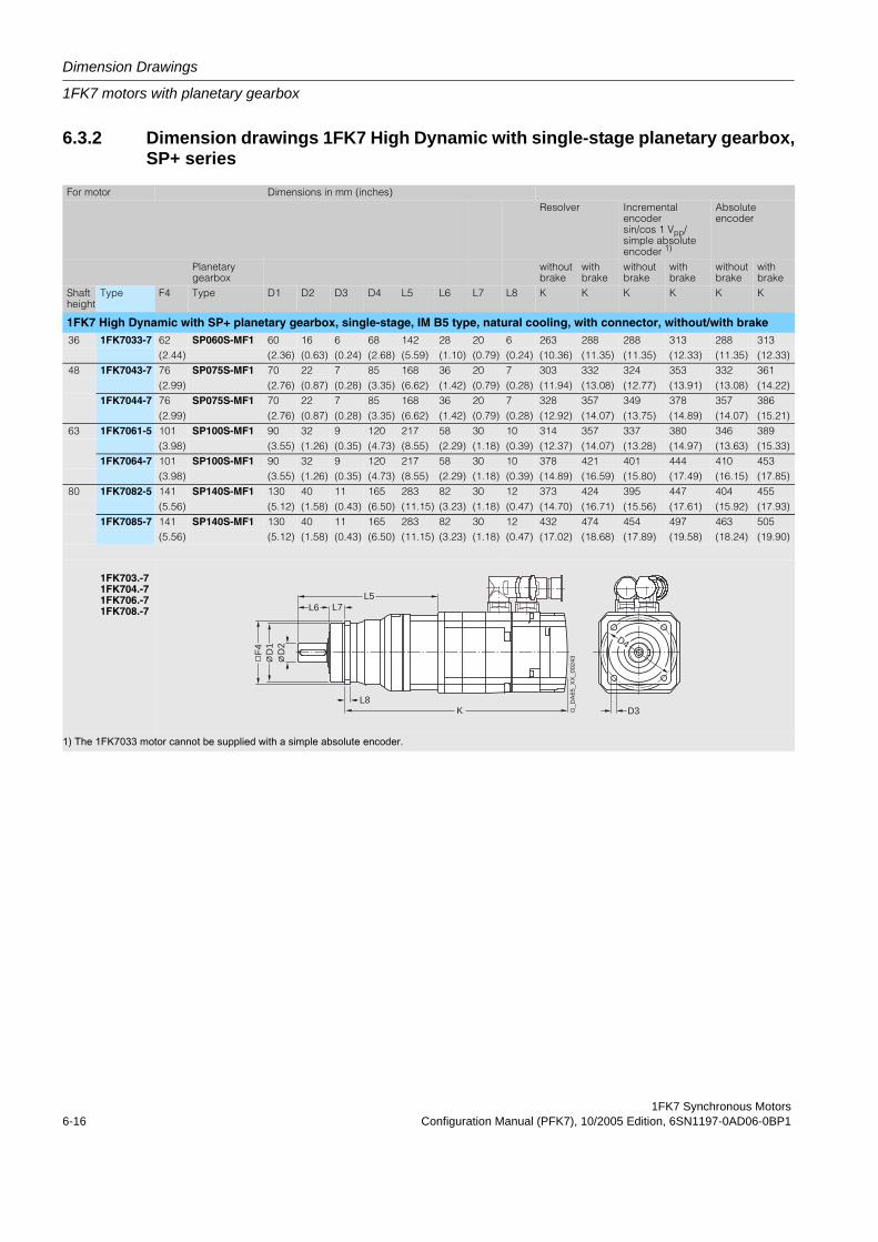
Dimension Drawings
1FK7 motors with planetary gearbox
1FK7 Synchronous Motors6-16 Configuration Manual (PFK7), 10/2005 Edition, 6SN1197-0AD06-0BP1
6.3.2 Dimension drawings 1FK7 High Dynamic with single-stage planetary gearbox,SP+ series
For motor Dimensions in mm (inches)Resolver Incremental
encoder sin/cos 1 Vpp/simple absolute encoder 1)
Absolute encoder
Planetary gearbox
without brake
with brake
without brake
with brake
without brake
with brake
Shaft height
Type F4 Type D1 D2 D3 D4 L5 L6 L7 L8 K K K K K K
1FK7 High Dynamic with SP+ planetary gearbox, single-stage, IM B5 type, natural cooling, with connector, without/with brake 36 1FK7033-7 62 SP060S-MF1 60 16 6 68 142 28 20 6 263 288 288 313 288 313
(2.44) (2.36) (0.63) (0.24) (2.68) (5.59) (1.10) (0.79) (0.24) (10.36) (11.35) (11.35) (12.33) (11.35) (12.33) 48 1FK7043-7 76 SP075S-MF1 70 22 7 85 168 36 20 7 303 332 324 353 332 361
(2.99) (2.76) (0.87) (0.28) (3.35) (6.62) (1.42) (0.79) (0.28) (11.94) (13.08) (12.77) (13.91) (13.08) (14.22)1FK7044-7 76 SP075S-MF1 70 22 7 85 168 36 20 7 328 357 349 378 357 386
(2.99) (2.76) (0.87) (0.28) (3.35) (6.62) (1.42) (0.79) (0.28) (12.92) (14.07) (13.75) (14.89) (14.07) (15.21) 63 1FK7061-5 101 SP100S-MF1 90 32 9 120 217 58 30 10 314 357 337 380 346 389
(3.98) (3.55) (1.26) (0.35) (4.73) (8.55) (2.29) (1.18) (0.39) (12.37) (14.07) (13.28) (14.97) (13.63) (15.33)1FK7064-7 101 SP100S-MF1 90 32 9 120 217 58 30 10 378 421 401 444 410 453
(3.98) (3.55) (1.26) (0.35) (4.73) (8.55) (2.29) (1.18) (0.39) (14.89) (16.59) (15.80) (17.49) (16.15) (17.85) 80 1FK7082-5 141 SP140S-MF1 130 40 11 165 283 82 30 12 373 424 395 447 404 455
(5.56) (5.12) (1.58) (0.43) (6.50) (11.15) (3.23) (1.18) (0.47) (14.70) (16.71) (15.56) (17.61) (15.92) (17.93)1FK7085-7 141 SP140S-MF1 130 40 11 165 283 82 30 12 432 474 454 497 463 505
(5.56) (5.12) (1.58) (0.43) (6.50) (11.15) (3.23) (1.18) (0.47) (17.02) (18.68) (17.89) (19.58) (18.24) (19.90)
1FK703.-71FK704.-71FK706.-71FK708.-7
1) The 1FK7033 motor cannot be supplied with a simple absolute encoder.
L6L5
L7
G_D
A65
_XX
_002
43
D3
D4
KL8
D2
D1
Ø Ø
F4
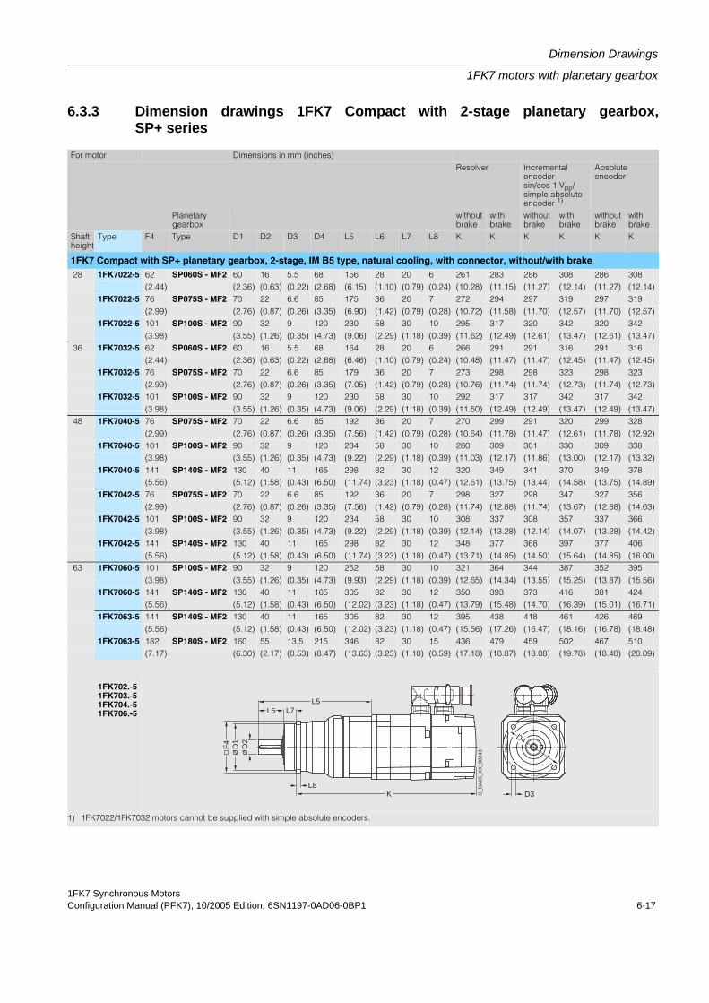
1FK7 Synchronous MotorsConfiguration Manual (PFK7), 10/2005 Edition, 6SN1197-0AD06-0BP1 6-17
Dimension Drawings
1FK7 motors with planetary gearbox
6.3.3 Dimension drawings 1FK7 Compact with 2-stage planetary gearbox,SP+ series
For motor Dimensions in mm (inches)Resolver Incremental
encoder sin/cos 1 Vpp/simple absolute encoder 1)
Absolute encoder
Planetary gearbox
without brake
with brake
without brake
with brake
without brake
with brake
Shaft height
Type F4 Type D1 D2 D3 D4 L5 L6 L7 L8 K K K K K K
1FK7 Compact with SP+ planetary gearbox, 2-stage, IM B5 type, natural cooling, with connector, without/with brake 28 1FK7022-5 62 SP060S - MF2 60 16 5.5 68 156 28 20 6 261 283 286 308 286 308
(2.44) (2.36) (0.63) (0.22) (2.68) (6.15) (1.10) (0.79) (0.24) (10.28) (11.15) (11.27) (12.14) (11.27) (12.14)1FK7022-5 76 SP075S - MF2 70 22 6.6 85 175 36 20 7 272 294 297 319 297 319
(2.99) (2.76) (0.87) (0.26) (3.35) (6.90) (1.42) (0.79) (0.28) (10.72) (11.58) (11.70) (12.57) (11.70) (12.57)1FK7022-5 101 SP100S - MF2 90 32 9 120 230 58 30 10 295 317 320 342 320 342
(3.98) (3.55) (1.26) (0.35) (4.73) (9.06) (2.29) (1.18) (0.39) (11.62) (12.49) (12.61) (13.47) (12.61) (13.47) 36 1FK7032-5 62 SP060S - MF2 60 16 5.5 68 164 28 20 6 266 291 291 316 291 316
(2.44) (2.36) (0.63) (0.22) (2.68) (6.46) (1.10) (0.79) (0.24) (10.48) (11.47) (11.47) (12.45) (11.47) (12.45)1FK7032-5 76 SP075S - MF2 70 22 6.6 85 179 36 20 7 273 298 298 323 298 323
(2.99) (2.76) (0.87) (0.26) (3.35) (7.05) (1.42) (0.79) (0.28) (10.76) (11.74) (11.74) (12.73) (11.74) (12.73)1FK7032-5 101 SP100S - MF2 90 32 9 120 230 58 30 10 292 317 317 342 317 342
(3.98) (3.55) (1.26) (0.35) (4.73) (9.06) (2.29) (1.18) (0.39) (11.50) (12.49) (12.49) (13.47) (12.49) (13.47) 48 1FK7040-5 76 SP075S - MF2 70 22 6.6 85 192 36 20 7 270 299 291 320 299 328
(2.99) (2.76) (0.87) (0.26) (3.35) (7.56) (1.42) (0.79) (0.28) (10.64) (11.78) (11.47) (12.61) (11.78) (12.92)1FK7040-5 101 SP100S - MF2 90 32 9 120 234 58 30 10 280 309 301 330 309 338
(3.98) (3.55) (1.26) (0.35) (4.73) (9.22) (2.29) (1.18) (0.39) (11.03) (12.17) (11.86) (13.00) (12.17) (13.32)1FK7040-5 141 SP140S - MF2 130 40 11 165 298 82 30 12 320 349 341 370 349 378
(5.56) (5.12) (1.58) (0.43) (6.50) (11.74) (3.23) (1.18) (0.47) (12.61) (13.75) (13.44) (14.58) (13.75) (14.89)1FK7042-5 76 SP075S - MF2 70 22 6.6 85 192 36 20 7 298 327 298 347 327 356
(2.99) (2.76) (0.87) (0.26) (3.35) (7.56) (1.42) (0.79) (0.28) (11.74) (12.88) (11.74) (13.67) (12.88) (14.03)1FK7042-5 101 SP100S - MF2 90 32 9 120 234 58 30 10 308 337 308 357 337 366
(3.98) (3.55) (1.26) (0.35) (4.73) (9.22) (2.29) (1.18) (0.39) (12.14) (13.28) (12.14) (14.07) (13.28) (14.42)1FK7042-5 141 SP140S - MF2 130 40 11 165 298 82 30 12 348 377 368 397 377 406
(5.56) (5.12) (1.58) (0.43) (6.50) (11.74) (3.23) (1.18) (0.47) (13.71) (14.85) (14.50) (15.64) (14.85) (16.00) 63 1FK7060-5 101 SP100S - MF2 90 32 9 120 252 58 30 10 321 364 344 387 352 395
(3.98) (3.55) (1.26) (0.35) (4.73) (9.93) (2.29) (1.18) (0.39) (12.65) (14.34) (13.55) (15.25) (13.87) (15.56)1FK7060-5 141 SP140S - MF2 130 40 11 165 305 82 30 12 350 393 373 416 381 424
(5.56) (5.12) (1.58) (0.43) (6.50) (12.02) (3.23) (1.18) (0.47) (13.79) (15.48) (14.70) (16.39) (15.01) (16.71)1FK7063-5 141 SP140S - MF2 130 40 11 165 305 82 30 12 395 438 418 461 426 469
(5.56) (5.12) (1.58) (0.43) (6.50) (12.02) (3.23) (1.18) (0.47) (15.56) (17.26) (16.47) (18.16) (16.78) (18.48)1FK7063-5 182 SP180S - MF2 160 55 13.5 215 346 82 30 15 436 479 459 502 467 510
(7.17) (6.30) (2.17) (0.53) (8.47) (13.63) (3.23) (1.18) (0.59) (17.18) (18.87) (18.08) (19.78) (18.40) (20.09)
1FK702.-51FK703.-51FK704.-51FK706.-5
1) 1FK7022/1FK7032 motors cannot be supplied with simple absolute encoders.
L6L5
L7
G_D
A65
_XX
_002
43
D3
D4
KL8
D2
D1
Ø Ø
F4
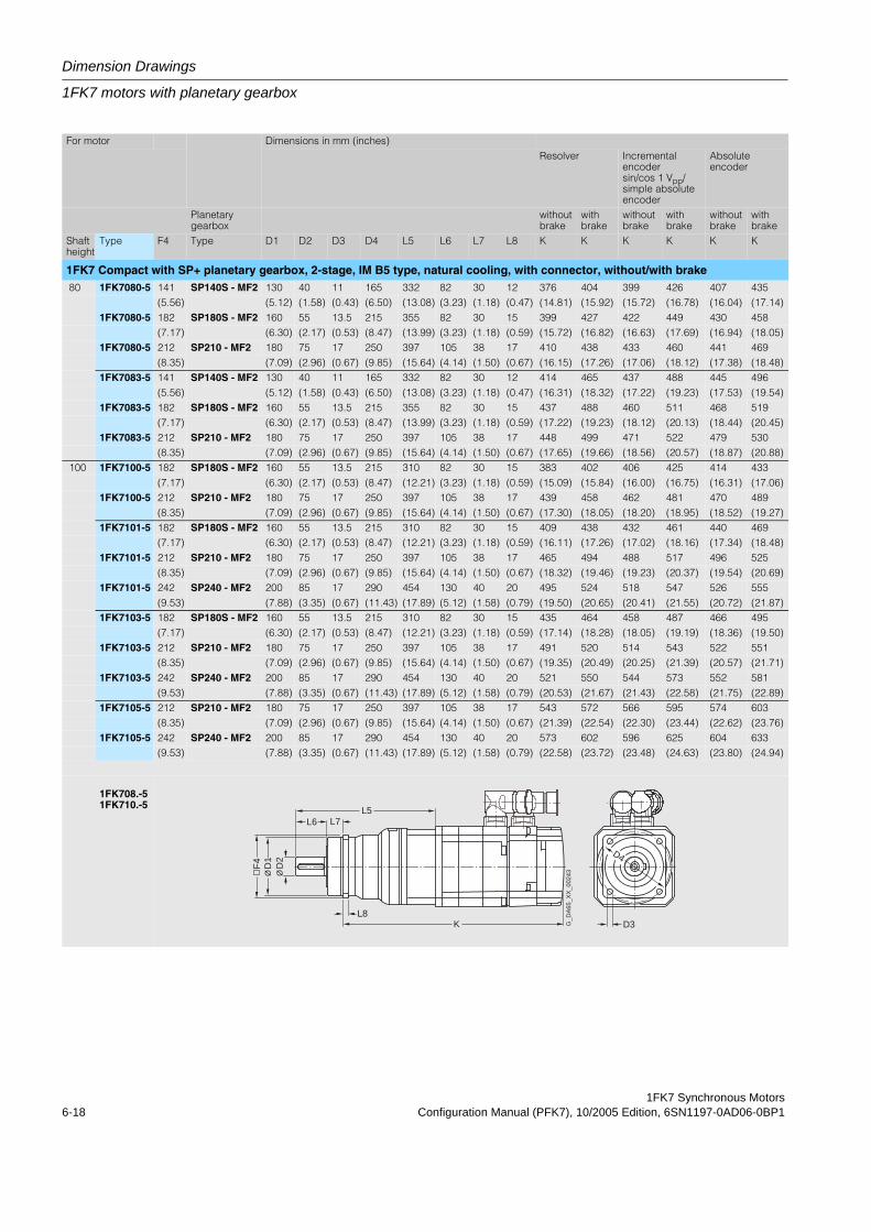
Dimension Drawings
1FK7 motors with planetary gearbox
1FK7 Synchronous Motors6-18 Configuration Manual (PFK7), 10/2005 Edition, 6SN1197-0AD06-0BP1
For motor Dimensions in mm (inches)Resolver Incremental
encoder sin/cos 1 Vpp/simple absolute encoder
Absolute encoder
Planetary gearbox
without brake
with brake
without brake
with brake
without brake
with brake
Shaft height
Type F4 Type D1 D2 D3 D4 L5 L6 L7 L8 K K K K K K
1FK7 Compact with SP+ planetary gearbox, 2-stage, IM B5 type, natural cooling, with connector, without/with brake 80 1FK7080-5 141 SP140S - MF2 130 40 11 165 332 82 30 12 376 404 399 426 407 435
(5.56) (5.12) (1.58) (0.43) (6.50) (13.08) (3.23) (1.18) (0.47) (14.81) (15.92) (15.72) (16.78) (16.04) (17.14)1FK7080-5 182 SP180S - MF2 160 55 13.5 215 355 82 30 15 399 427 422 449 430 458
(7.17) (6.30) (2.17) (0.53) (8.47) (13.99) (3.23) (1.18) (0.59) (15.72) (16.82) (16.63) (17.69) (16.94) (18.05)1FK7080-5 212 SP210 - MF2 180 75 17 250 397 105 38 17 410 438 433 460 441 469
(8.35) (7.09) (2.96) (0.67) (9.85) (15.64) (4.14) (1.50) (0.67) (16.15) (17.26) (17.06) (18.12) (17.38) (18.48)1FK7083-5 141 SP140S - MF2 130 40 11 165 332 82 30 12 414 465 437 488 445 496
(5.56) (5.12) (1.58) (0.43) (6.50) (13.08) (3.23) (1.18) (0.47) (16.31) (18.32) (17.22) (19.23) (17.53) (19.54)1FK7083-5 182 SP180S - MF2 160 55 13.5 215 355 82 30 15 437 488 460 511 468 519
(7.17) (6.30) (2.17) (0.53) (8.47) (13.99) (3.23) (1.18) (0.59) (17.22) (19.23) (18.12) (20.13) (18.44) (20.45)1FK7083-5 212 SP210 - MF2 180 75 17 250 397 105 38 17 448 499 471 522 479 530
(8.35) (7.09) (2.96) (0.67) (9.85) (15.64) (4.14) (1.50) (0.67) (17.65) (19.66) (18.56) (20.57) (18.87) (20.88) 100 1FK7100-5 182 SP180S - MF2 160 55 13.5 215 310 82 30 15 383 402 406 425 414 433
(7.17) (6.30) (2.17) (0.53) (8.47) (12.21) (3.23) (1.18) (0.59) (15.09) (15.84) (16.00) (16.75) (16.31) (17.06)1FK7100-5 212 SP210 - MF2 180 75 17 250 397 105 38 17 439 458 462 481 470 489
(8.35) (7.09) (2.96) (0.67) (9.85) (15.64) (4.14) (1.50) (0.67) (17.30) (18.05) (18.20) (18.95) (18.52) (19.27)1FK7101-5 182 SP180S - MF2 160 55 13.5 215 310 82 30 15 409 438 432 461 440 469
(7.17) (6.30) (2.17) (0.53) (8.47) (12.21) (3.23) (1.18) (0.59) (16.11) (17.26) (17.02) (18.16) (17.34) (18.48)1FK7101-5 212 SP210 - MF2 180 75 17 250 397 105 38 17 465 494 488 517 496 525
(8.35) (7.09) (2.96) (0.67) (9.85) (15.64) (4.14) (1.50) (0.67) (18.32) (19.46) (19.23) (20.37) (19.54) (20.69)1FK7101-5 242 SP240 - MF2 200 85 17 290 454 130 40 20 495 524 518 547 526 555
(9.53) (7.88) (3.35) (0.67) (11.43) (17.89) (5.12) (1.58) (0.79) (19.50) (20.65) (20.41) (21.55) (20.72) (21.87)1FK7103-5 182 SP180S - MF2 160 55 13.5 215 310 82 30 15 435 464 458 487 466 495
(7.17) (6.30) (2.17) (0.53) (8.47) (12.21) (3.23) (1.18) (0.59) (17.14) (18.28) (18.05) (19.19) (18.36) (19.50)1FK7103-5 212 SP210 - MF2 180 75 17 250 397 105 38 17 491 520 514 543 522 551
(8.35) (7.09) (2.96) (0.67) (9.85) (15.64) (4.14) (1.50) (0.67) (19.35) (20.49) (20.25) (21.39) (20.57) (21.71)1FK7103-5 242 SP240 - MF2 200 85 17 290 454 130 40 20 521 550 544 573 552 581
(9.53) (7.88) (3.35) (0.67) (11.43) (17.89) (5.12) (1.58) (0.79) (20.53) (21.67) (21.43) (22.58) (21.75) (22.89)1FK7105-5 212 SP210 - MF2 180 75 17 250 397 105 38 17 543 572 566 595 574 603
(8.35) (7.09) (2.96) (0.67) (9.85) (15.64) (4.14) (1.50) (0.67) (21.39) (22.54) (22.30) (23.44) (22.62) (23.76)1FK7105-5 242 SP240 - MF2 200 85 17 290 454 130 40 20 573 602 596 625 604 633
(9.53) (7.88) (3.35) (0.67) (11.43) (17.89) (5.12) (1.58) (0.79) (22.58) (23.72) (23.48) (24.63) (23.80) (24.94)
1FK708.-51FK710.-5
L6L5
L7
G_D
A65
_XX
_002
43
D3
D4
KL8
D2
D1
Ø Ø
F4

1FK7 Synchronous MotorsConfiguration Manual (PFK7), 10/2005 Edition, 6SN1197-0AD06-0BP1 6-19
Dimension Drawings
1FK7 motors with planetary gearbox
6.3.4 Dimension drawings 1FK7 High Dynamic with 2-stage planetary gearbox,SP+ series
For motor Dimensions in mm (inches)Resolver Incremental en-
coder sin/cos 1 Vpp/simple absolute encoder 1)
Absolute encoder
Planetary gearbox
without brake
with brake
without brake
with brake
without brake
with brake
Shaft height
Type F4 Type D1 D2 D3 D4 L5 L6 L7 L8 K K K K K K
1FK7 High Dynamic with SP+ planetary gearbox, 2-stage, IM B5 type, natural cooling, with connector, without/with brake36 1FK7033-7 62 SP060S - MF2 60 16 5.5 68 164 28 20 6 285 310 310 335 310 335
(2.44) (2.36) (0.63) (0.22) (2.68) (6.46) (1.10) (0.79) (0.24) (11.23) (12.21) (12.21) (13.20) (12.21) (13.20)1FK7033-7 76 SP075S - MF2 70 22 6.6 85 179 36 20 7 292 317 317 342 317 342
(2.99) (2.76) (0.87) (0.26) (3.35) (7.05) (1.42) (0.79) (0.28) (11.50) (12.49) (12.49) (13.47) (12.49) (13.47)1FK7033-7 101 SP100S - MF2 90 32 9 120 230 58 30 10 311 336 336 361 336 361
(3.98) (3.55) (1.26) (0.35) (4.73) (9.06) (2.29) (1.18) (0.39) (12.25) (13.24) (13.24) (14.22) (13.24) (14.22) 48 1FK7043-7 76 SP075S - MF2 70 22 6.6 85 192 36 20 7 327 356 348 377 356 385
(2.99) (2.76) (0.87) (0.26) (3.35) (7.56) (1.42) (0.79) (0.28) (12.88) (14.03) (13.71) (14.85) (14.03) (15.17)1FK7043-7 101 SP100S - MF2 90 32 9 120 234 58 30 10 337 366 358 387 366 395
(3.98) (3.55) (1.26) (0.35) (4.73) (9.22) (2.29) (1.18) (0.39) (13.28) (14.42) (14.11) (15.25) (14.42) (15.56)1FK7043-7 141 SP140S - MF2 130 40 11 165 298 82 30 12 377 406 398 427 406 435
(5.56) (5.12) (1.58) (0.43) (6.50) (11.74) (3.23) (1.18) (0.47) (14.85) (16.00) (15.68) (16.82) (16.00) (17.14)1FK7044-7 101 SP100S - MF2 90 32 9 120 234 58 30 10 362 391 383 412 391 420
(3.98) (3.55) (1.26) (0.35) (4.73) (9.22) (2.29) (1.18) (0.39) (14.26) (15.41) (15.09) (16.23) (15.41) (16.55)1FK7044-7 141 SP140S - MF2 130 40 11 165 298 82 30 12 402 431 432 452 431 460
(5.56) (5.12) (1.58) (0.43) (6.50) (11.74) (3.23) (1.18) (0.47) (15.84) (16.98) (17.02) (17.81) (16.98) (18.12) 63 1FK7061-7 101 SP100S - MF2 90 32 9 120 252 58 30 10 349 392 372 415 381 424
(3.98) (3.55) (1.26) (0.35) (4.73) (9.93) (2.29) (1.18) (0.39) (13.75) (15.44) (14.66) (16.35) (15.01) (16.71)1FK7061-7 141 SP140S - MF2 130 40 11 165 305 82 30 12 378 421 401 444 410 453
(5.56) (5.12) (1.58) (0.43) (6.50) (12.02) (3.23) (1.18) (0.47) (14.89) (16.59) (15.80) (17.49) (16.15) (17.85)1FK7064-7 141 SP140S - MF2 130 40 11 165 305 82 30 12 442 485 465 508 474 517
(5.56) (5.12) (1.58) (0.43) (6.50) (12.02) (3.23) (1.18) (0.47) (17.41) (19.11) (18.32) (20.02) (18.68) (20.37) 80 1FK7082-7 141 SP140S - MF2 130 40 11 165 332 82 30 12 422 473 444 496 453 504
(5.56) (5.12) (1.58) (0.43) (6.50) (13.08) (3.23) (1.18) (0.47) (16.63) (18.64) (17.49) (19.54) (17.85) (19.86)1FK7082-7 182 SP180S - MF2 160 55 13.5 215 355 82 30 15 445 496 467 519 476 527
(7.17) (6.30) (2.17) (0.53) (8.47) (13.99) (3.23) (1.18) (0.59) (17.53) (19.54) (18.40) (20.45) (18.75) (20.76)1FK7082-7 212 SP210 - MF2 180 75 17 250 397 105 38 17 456 507 478 530 487 538
(8.35) (7.09) (2.96) (0.67) (9.85) (15.64) (4.14) (1.50) (0.67) (17.97) (19.98) (18.83) (20.88) (19.19) (21.20)1FK7085-7 141 SP140S - MF2 130 40 11 165 332 82 30 12 481 523 503 546 512 554
(5.56) (5.12) (1.58) (0.43) (6.50) (13.08) (3.23) (1.18) (0.47) (18.95) (20.61) (19.82) (21.51) (20.17) (21.83)1FK7085-7 212 SP210 - MF2 180 75 17 250 397 105 38 17 515 557 537 580 546 588
(8.35) (7.09) (2.96) (0.67) (9.85) (15.64) (4.14) (1.50) (0.67) (20.29) (21.95) (21.16) (22.85) (21.51) (23.17)
1FK 703.-71FK 704.-71FK 706.-71FK 708.-7
1) The 1FK7033 motor cannot be supplied with a simple absolute encoder.
L6L5
L7
G_D
A65
_XX
_002
43
D3
D4
KL8
D2
D1
Ø Ø
F4
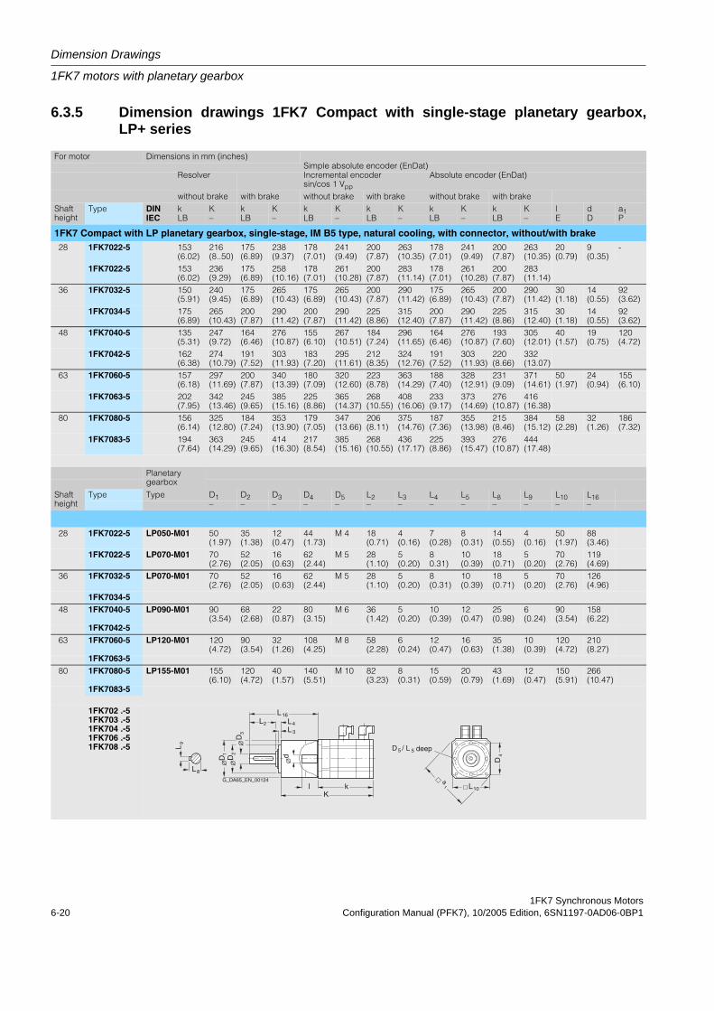
Dimension Drawings
1FK7 motors with planetary gearbox
1FK7 Synchronous Motors6-20 Configuration Manual (PFK7), 10/2005 Edition, 6SN1197-0AD06-0BP1
6.3.5 Dimension drawings 1FK7 Compact with single-stage planetary gearbox,LP+ series
For motor Dimensions in mm (inches)Simple absolute encoder (EnDat)
Resolver Incremental encoder sin/cos 1 Vpp
Absolute encoder (EnDat)
without brake with brake without brake with brake without brake with brakeShaft height
Type DIN k K k K k K k K k K k K l d a1IEC LB – LB – LB – LB – LB – LB – E D P
1FK7 Compact with LP planetary gearbox, single-stage, IM B5 type, natural cooling, with connector, without/with brake28 1FK7022-5 153
(6.02)216(8..50)
175(6.89)
238(9.37)
178(7.01)
241(9.49)
200(7.87)
263(10.35)
178(7.01)
241(9.49)
200(7.87)
263(10.35)
20(0.79)
9(0.35)
-
1FK7022-5 153(6.02)
236(9.29)
175(6.89)
258(10.16)
178(7.01)
261(10.28)
200(7.87)
283(11.14)
178(7.01)
261(10.28)
200(7.87)
283(11.14)
36 1FK7032-5 150(5.91)
240(9.45)
175(6.89)
265(10.43)
175(6.89)
265(10.43)
200(7.87)
290(11.42)
175(6.89)
265(10.43)
200(7.87)
290(11.42)
30(1.18)
14(0.55)
92(3.62)
1FK7034-5 175(6.89)
265(10.43)
200(7.87)
290(11.42)
200(7.87)
290(11.42)
225(8.86)
315(12.40)
200(7.87)
290(11.42)
225(8.86)
315(12.40)
30(1.18)
14(0.55)
92(3.62)
48 1FK7040-5 135(5.31)
247(9.72)
164(6.46)
276(10.87)
155(6.10)
267(10.51)
184(7.24)
296(11.65)
164(6.46)
276(10.87)
193(7.60)
305(12.01)
40(1.57)
19(0.75)
120(4.72)
1FK7042-5 162(6.38)
274(10.79)
191(7.52)
303(11.93)
183(7.20)
295(11.61)
212(8.35)
324(12.76)
191(7.52)
303(11.93)
220(8.66)
332(13.07)
63 1FK7060-5 157(6.18)
297(11.69)
200(7.87)
340(13.39)
180(7.09)
320(12.60)
223(8.78)
363(14.29)
188(7.40)
328(12.91)
231(9.09)
371(14.61)
50(1.97)
24(0.94)
155(6.10)
1FK7063-5 202(7.95)
342(13.46)
245(9.65)
385(15.16)
225(8.86)
365(14.37)
268(10.55)
408(16.06)
233(9.17)
373(14.69)
276(10.87)
416(16.38)
80 1FK7080-5 156(6.14)
325(12.80)
184(7.24)
353(13.90)
179(7.05)
347(13.66)
206(8.11)
375(14.76)
187(7.36)
355(13.98)
215(8.46)
384(15.12)
58(2.28)
32(1.26)
186(7.32)
1FK7083-5 194(7.64)
363(14.29)
245(9.65)
414(16.30)
217(8.54)
385(15.16)
268(10.55)
436(17.17)
225(8.86)
393(15.47)
276(10.87)
444(17.48)
Planetary gearbox
Shaft height
Type Type D1 D2 D3 D4 D5 L2 L3 L4 L5 L8 L9 L10 L16– – – – – – – – – – – – –
28 1FK7022-5 LP050-M01 50(1.97)
35(1.38)
12(0.47)
44(1.73)
M 4 18(0.71)
4(0.16)
7(0.28)
8(0.31)
14(0.55)
4(0.16)
50(1.97)
88(3.46)
1FK7022-5 LP070-M01 70(2.76)
52(2.05)
16(0.63)
62(2.44)
M 5 28(1.10)
5(0.20)
80.31)
10(0.39)
18(0.71)
5(0.20)
70(2.76)
119(4.69)
36 1FK7032-5 LP070-M01 70(2.76)
52(2.05)
16(0.63)
62(2.44)
M 5 28(1.10)
5(0.20)
8(0.31)
10(0.39)
18(0.71)
5(0.20)
70(2.76)
126(4.96)
1FK7034-548 1FK7040-5 LP090-M01 90
(3.54)68(2.68)
22(0.87)
80(3.15)
M 6 36(1.42)
5(0.20)
10(0.39)
12(0.47)
25(0.98)
6(0.24)
90(3.54)
158(6.22)
1FK7042-563 1FK7060-5 LP120-M01 120
(4.72)90(3.54)
32(1.26)
108(4.25)
M 8 58(2.28)
6(0.24)
12(0.47)
16(0.63)
35(1.38)
10(0.39)
120(4.72)
210(8.27)
1FK7063-580 1FK7080-5 LP155-M01 155
(6.10)120(4.72)
40(1.57)
140(5.51)
M 10 82(3.23)
8(0.31)
15(0.59)
20(0.79)
43(1.69)
12(0.47)
150(5.91)
266(10.47)
1FK7083-5
1FK702 .-51FK703 .-51FK704 .-51FK706 .-51FK708 .-5
D
L
a
d
L
D
klK
LLL
L
D
L
8
9
1
3
16
4
3
2
110
4D2
deepD / L5 5
G_DA65_EN_00124
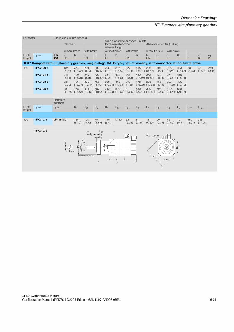
1FK7 Synchronous MotorsConfiguration Manual (PFK7), 10/2005 Edition, 6SN1197-0AD06-0BP1 6-21
Dimension Drawings
1FK7 motors with planetary gearbox
For motor Dimensions in mm (inches)Simple absolute encoder (EnDat)
Resolver Incremental encoder sin/cos 1 Vpp
Absolute encoder (EnDat)
without brake with brake without brake with brake without brake with brakeShaft height
Type DIN k K k K k K k K k K k K l d a1IEC LB – LB – LB – LB – LB – LB – E D P
1FK7 Compact with LP planetary gearbox, single-stage, IM B5 type, natural cooling, with connector, without/with brake100 1FK7100-5 185
(7.28)374(14.72)
204(8.03)
393(15.47)
208(8.19)
396(15.59)
227(8.94)
415(16.34)
216(8.50)
404(15.91)
235(9.25)
423(16.65)
80(3.15)
38(1.50)
240(9.45)
1FK7101-5 211(8.31)
400(15.75)
240(9.45)
429(16.89)
234(9.21)
422(16.61)
263(10.35)
452(17.80)
242(9.53)
430(16.93)
271(10.67)
460(18.11)
1FK7103-5 237(9.33)
426(16.77)
266(10.47)
455(17.91)
260(10.24)
448(17.64)
28911.38)
478(18.82)
268(10.55)
456(17.95)
297(11.69)
486(19.13)
1FK7105-5 289(11.38)
478(18.82)
318(12.52)
507(19.96)
312(12.28)
500(19.69)
341(13.43)
530(20.87)
320(12.60)
508(20.00)
349(13.74)
538(21.18)
Planetary gearbox
Shaft height
Type Type D1 D2 D3 D4 D5 L2 L3 L4 L5 L8 L9 L10 L16– – – – – – – – – – – – –
100 1FK710.-5 LP155-M01 155(6.10)
120(4.72)
40(1.57)
140(5.51)
M 10 82(3.23)
8(0.31)
15(0.59)
20(0.79)
43(1.69)
12(0.47)
150(5.91)
286(11.26)
1FK710.-5
D
L
d
L
DD
klK
LLLL
8
9
1 2
3
16
4
3
2
L10
a
1
D4
D / L deep5 5
G_DA65_EN_00125
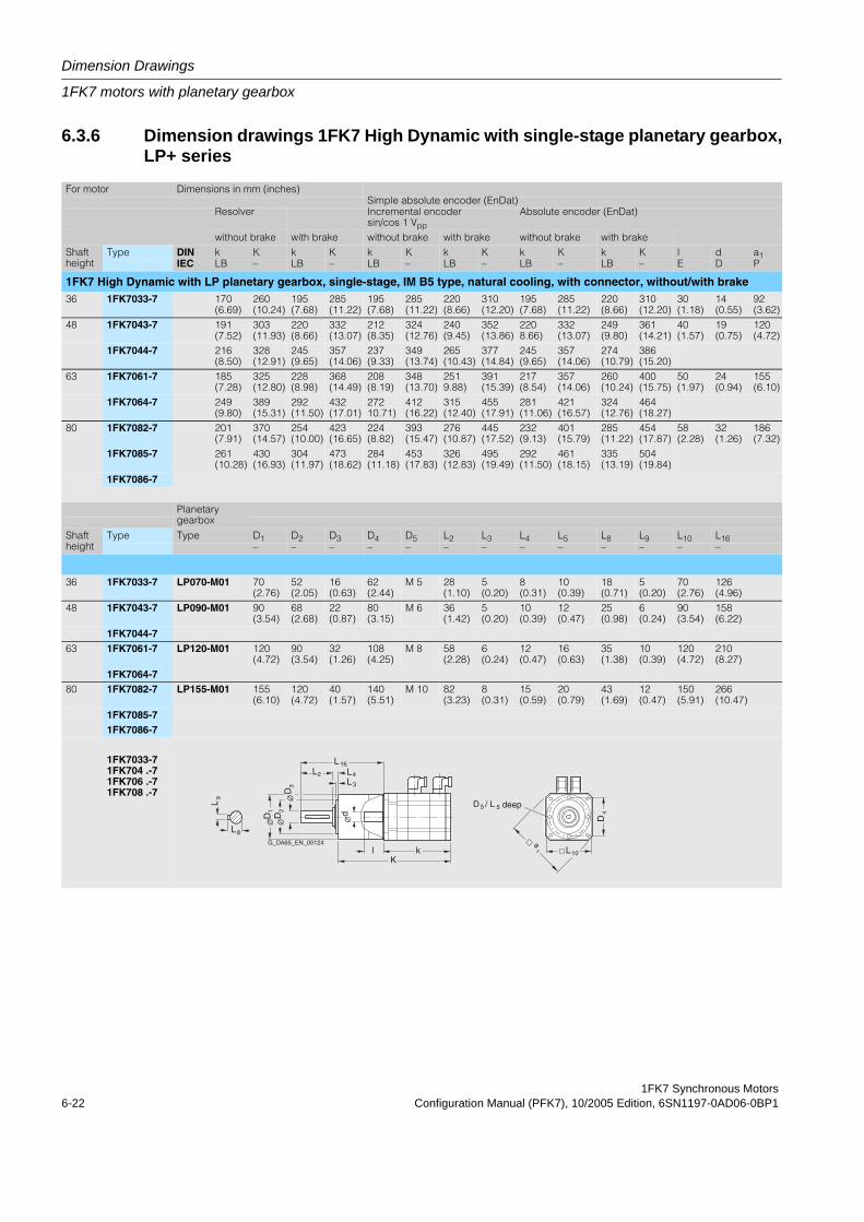
Dimension Drawings
1FK7 motors with planetary gearbox
1FK7 Synchronous Motors6-22 Configuration Manual (PFK7), 10/2005 Edition, 6SN1197-0AD06-0BP1
6.3.6 Dimension drawings 1FK7 High Dynamic with single-stage planetary gearbox,LP+ series
For motor Dimensions in mm (inches)Simple absolute encoder (EnDat)
Resolver Incremental encoder sin/cos 1 Vpp
Absolute encoder (EnDat)
without brake with brake without brake with brake without brake with brakeShaft height
Type DIN k K k K k K k K k K k K l d a1IEC LB – LB – LB – LB – LB – LB – E D P
1FK7 High Dynamic with LP planetary gearbox, single-stage, IM B5 type, natural cooling, with connector, without/with brake36 1FK7033-7 170
(6.69)260(10.24)
195(7.68)
285(11.22)
195(7.68)
285(11.22)
220(8.66)
310(12.20)
195(7.68)
285(11.22)
220(8.66)
310(12.20)
30(1.18)
14(0.55)
92(3.62)
48 1FK7043-7 191(7.52)
303(11.93)
220(8.66)
332(13.07)
212(8.35)
324(12.76)
240(9.45)
352(13.86)
2208.66)
332(13.07)
249(9.80)
361(14.21)
40(1.57)
19(0.75)
120(4.72)
1FK7044-7 216(8.50)
328(12.91)
245(9.65)
357(14.06)
237(9.33)
349(13.74)
265(10.43)
377(14.84)
245(9.65)
357(14.06)
274(10.79)
386(15.20)
63 1FK7061-7 185(7.28)
325(12.80)
228(8.98)
368(14.49)
208(8.19)
348(13.70)
2519.88)
391(15.39)
217(8.54)
357(14.06)
260(10.24)
400(15.75)
50(1.97)
24(0.94)
155(6.10)
1FK7064-7 249(9.80)
389(15.31)
292(11.50)
432(17.01)
27210.71)
412(16.22)
315(12.40)
455(17.91)
281(11.06)
421(16.57)
324(12.76)
464(18.27)
80 1FK7082-7 201(7.91)
370(14.57)
254(10.00)
423(16.65)
224(8.82)
393(15.47)
276(10.87)
445(17.52)
232(9.13)
401(15.79)
285(11.22)
454(17.87)
58(2.28)
32(1.26)
186(7.32)
1FK7085-7 261(10.28)
430(16.93)
304(11.97)
473(18.62)
284(11.18)
453(17.83)
326(12.83)
495(19.49)
292(11.50)
461(18.15)
335(13.19)
504(19.84)
1FK7086-7
Planetary gearbox
Shaft height
Type Type D1 D2 D3 D4 D5 L2 L3 L4 L5 L8 L9 L10 L16– – – – – – – – – – – – –
36 1FK7033-7 LP070-M01 70(2.76)
52(2.05)
16(0.63)
62(2.44)
M 5 28(1.10)
5(0.20)
8(0.31)
10(0.39)
18(0.71)
5(0.20)
70(2.76)
126(4.96)
48 1FK7043-7 LP090-M01 90(3.54)
68(2.68)
22(0.87)
80(3.15)
M 6 36(1.42)
5(0.20)
10(0.39)
12(0.47)
25(0.98)
6(0.24)
90(3.54)
158(6.22)
1FK7044-763 1FK7061-7 LP120-M01 120
(4.72)90(3.54)
32(1.26)
108(4.25)
M 8 58(2.28)
6(0.24)
12(0.47)
16(0.63)
35(1.38)
10(0.39)
120(4.72)
210(8.27)
1FK7064-780 1FK7082-7 LP155-M01 155
(6.10)120(4.72)
40(1.57)
140(5.51)
M 10 82(3.23)
8(0.31)
15(0.59)
20(0.79)
43(1.69)
12(0.47)
150(5.91)
266(10.47)
1FK7085-71FK7086-7
1FK7033-71FK704 .-71FK706 .-71FK708 .-7 D
L
a
d
L
D
klK
LLL
L
D
L
8
9
1
3
16
4
3
2
110
4D2
deepD / L5 5
G_DA65_EN_00124
1FK7 Synchronous MotorsConfiguration Manual (PFK7), 10/2005 Edition, 6SN1197-0AD06-0BP1 A-1
Appendix AA.1 References
An overview of publications that is updated monthly is provided in a number of languages in the Internet at:
<http://www.siemens.com/motioncontrol>through "Support", "Technical Documentation", "Documentation Overview"
General Documentation
Electronic Documentation
/D 21.2/ SINAMICS S120 Catalog
SINAMICS S120 Servo Control Drive System
/NC 61/ SINUMERIK and SIMODRIVE Catalog
Automation Systems for Machine Tools
/DA65.3/ SIMOVERT MASTERDRIVES Catalog
Synchronous and Induction Motors for SIMOVERT MASTERDRIVES
/CD1/ DOC ON CD
The SINUMERIK System (includes all SINUMERIK 840D/810D and SIMODRIVE 611D)
/CD2/ DOC ON CD
The SINAMICS System
Appendix
References
1FK7 Synchronous MotorsA-2 Configuration Manual (PFK7), 10/2005 Edition, 6SN1197-0AD06-0BP1
Manufacturer/Service Documentation
/PJAL/ Configuration Manual, Synchronous Motors
SIMODRIVE 611, SIMOVERT MASTERDRIVES Synchronous Motors General Section
/PFK7S/ Configuration Manual, Synchronous Motors
SINAMICS S1201FK7 Synchronous Motors
/PFT6S/ Configuration Manual, Synchronous Motors
SINAMICS S1201FT6 Synchronous Motors
/APH7S/ Configuration Manual, Asynchronous Motors
SINAMICS S120Servo Control/Vector ControlInduction Motors 1PH7
/PMH2/ Configuration Manual, Hollow-Shaft Measuring System
SINAMICS S120, SIMODRIVE 611, SIMOVERT MASTERDRIVES, SIMAG H2 Hollow-Shaft Measuring System
/PJM2/ Configuration Manual, Synchronous Motors
SIMODRIVE 611, SIMOVERT MASTERDRIVES Synchronous Motors General Section Section, 1FT5, 1FT6, 1FK6, 1FK7
/PFK7/ Configuration Manual, Synchronous Motors
SIMODRIVE 611, SIMOVERT MASTERDRIVES 1FK7 Synchronous Motors
/PFT6/ Configuration Manual, Synchronous Motors
SIMODRIVE 611, SIMOVERT MASTERDRIVES 1FT6 Synchronous Motors
/PFK6/ Configuration Manual, Synchronous Motors
SIMODRIVE 611, SIMOVERT MASTERDRIVES 1FK6 Synchronous Motors
/PFS6/ Configuration Manual, Synchronous Motors
SIMOVERT MASTERDRIVES1FS6 Synchronous Motors, Explosion-Protected
/PFU/ Configuration Manual, Synchronous Motors
SINAMICS S120, SIMOVERT MASTERDRIVES, MICROMASTERSIEMOSYN Synchronous Motors 1FU8
1FK7 Synchronous MotorsConfiguration Manual (PFK7), 10/2005 Edition, 6SN1197-0AD06-0BP1 A-3
Appendix
References
/ASAL/ Configuration Manual, Asynchronous Motors
SIMODRIVE 611, SIMOVERT MASTERDRIVES Asynchronous Motors General Section
/APH2/ Configuration Manual, Asynchronous Motors
SIMODRIVE 6111PH2 Asynchronous Motors
/APH4/ Configuration Manual, Asynchronous Motors
SIMODRIVE 6111PH4 Induction Motors
/APH7/ Configuration Manual, Asynchronous Motors
SIMODRIVE 6111PH7 Induction Motors
/PPM/ Configuration Manual, Hollow-Shaft Motors
SIMODRIVE 611Hollow Shaft Motors for Main Spindle Drives 1PM6 and 1PM4
/PJFE/ Configuration Manual, Synchronous Build-in Motors
SIMODRIVE 611Synchronous Motors for Main Spindle Drives1FE1 Synchronous Build-in Motors
/PJTM/ Configuration Manual, Build-in Torque Motors
SIMODRIVE 611Build-in Torque Motors 1FW6
/PJLM/ Configuration Manual, Linear Motors
SIMODRIVE 611Linear Motors 1FN1 and 1FN3
/PMS/ Configuration Manual, ECO Motor Spindle
SIMODRIVE 611ECO Motor Spindle 2SP1
/APL6/ Configuration Manual, Asynchronous Motors
SIMOVERT MASTERDRIVESInduction Motors 1PL6
Appendix
References
1FK7 Synchronous MotorsA-4 Configuration Manual (PFK7), 10/2005 Edition, 6SN1197-0AD06-0BP1
/APH7M/ Configuration Manual, Asynchronous Motors
SIMOVERT MASTERDRIVES VC/MCAsynchronous Motors 1PH7
/PKTM/ Configuration Manual, Complete Torque Motors
SIMOVERT MASTERDRIVES Complete Torque Motors 1FW3
I-11FK7 Synchronous MotorsConfiguration Manual (PFK7), 10/2005 Edition, 6SN1197-0AD06-0BP1
Index
AAbsolute encoder, 4-6Armature short-circuit braking, 1-12Axial force stressing, 3-48
BBraking Resistor, 1-14
CCantilever force stressing, 3-44Characteristics, 3-1Cooling, 1-8Coupling output, 1-10Coupling outputs, 1-9
DDanger and warning information, vDimension drawings, 6-1
EEncoders, 4-3, 4-4ESDS instructions, vii
HHolding brake, 4-10, 4-14Holding torque, 4-14Hotline, iv
IIncremental encoders, 4-4, 4-7
RResolver, 4-8
SSpeed-torque diagrams
1FK7 CT, 3-21FK7 HD, 3-28
TTechnical data
1FK7022, 3-21FK7032, 3-41FK7033, 3-281FK7040, 3-6, 3-81FK7042, 3-101FK7043, 3-301FK7044, 3-321FK7060, 3-121FK7061, 3-341FK7063, 3-141FK7064, 3-361FK7080, 3-161FK7082, 3-381FK7083, 3-181FK7085, 3-40, 3-421FK7100, 3-201FK7101, 3-221FK7103, 3-241FK7105, 3-26
Technical support, ivTemperature sensor, KTY 84, 4-1Thermal motor protection, 4-1
Index
I-2 1FK7 Synchronous MotorsConfiguration Manual (PFK7), 10/2005 Edition, 6SN1197-0AD06-0BP1
Recommendation
Corrections
To
SIEMENS AG
A&D MC BMS
Postfach 3180
D-91050 Erlangen
Tel.: +49 (0) 180 / 5050 - 222 (Hotline)
Fax.: +49 (0) 9131 / 98 - 63315 (Documentation)
email: [email protected]
for document:
1FK7 Synchronous Motors
SIMODRIVE 611 and
SIMOVERT MASTERDRIVES MC
Manufacturer/Service Documentation
Equipment Manual
Order no.: 6SN1197-0AD06-0BP1
Edition: 10/2005
From
Name
Your company address/dept.
Address
Postal code: City:
Phone: /
Fax: /
Should you come across any printing errors when
reading this publication, please notify us on this
sheet. Suggestions for improvement are also
welcome.
Recommendatinos and/or suggestions


© Siemens AG 2003-2005Subject to change without prior notice
Order No.: 6SN1197-0AD06-0BP1
Printed in the Federal Republic of Germany


