184
Aethra Gateway User Guide
Aethra GatewayUser Guide

NOTICE
© 2000-2006 Aethra SpA. All intellectual property rights in this publication are owned by Aethra SpA and are protected by United States copyright laws, other applicable copyright laws and international treaty provisions. Aethra SpA retains all rights not expressly granted. This publication is Aethra confidential. No part of this publication may be reproduced in any form whatsoever or used to make any derivative work without prior written approval by Aethra SpA. No representation of warranties for fitness for any purpose other than what is specifically mentioned in this guide is made either by Aethra SpA or its agents. Aethra SpA reserves the right to revise this publication and make changes without obligation to notify any person of such revisions or changes. Aethra SpA may make improvements or changes in the product(s) and/or the program(s) described in this documentation at any time. If there is any software on removable media described in this publication, it is furnished under a license agreement included with the product as a separate document. If you are unable to locate a copy, please contact Aethra SpA and a copy will be provided to you. Unless otherwise indicated, Aethra registered trademarks are registered in the United States and other territories. All registered trademarks recognized.For further information contact Aethra or your local distributor or reseller.
Gateway version 5.0, May 2006
http://www.aethra.com
Contents iii
About This ManualRelated Documentation ixConventions Used in this Manual ix
1111 FunctionalityAbout Aethra Gateway Products 1
About the Aethra P20 1About the Aethra B40 1
About Gateway Features 2About Aethra Gateway Applications and Topologies 8
About Multimedia Conferencing 8About Point-to-Point Conferencing 10About Multipoint Conferencing 10About Gateway IP Network Connections 11About Gateway ISDN Network Connections 11
About Aethra Gateway Functionality 14About PRI Gateway Call Handling Capacity 14About BRI Gateway Call handling Capacity 15About Gateway Call Bandwidth Overhead 15Resource Allocation across E1/T1 Lines 15About Peer-to-Peer Connectivity 16
2222 Setting Up Your Aethra GatewayPhysical Description 18
Front Panel 18Aethra P20 Rear Panel 19
CONTENTS
iv Aethra Gateway User Guide
Aethra B40 RTM 20Preparing for Installation 20Verifying the Package Contents 21Mounting the Aethra Gateway Unit in a 19-inch Rack 21Aethra Gateway Unit Initial Configuration 22
Connecting to a PC 23Setting the IP Address 23Changing the Configuration Tool Login Password 26
Connecting the Aethra Gateway Unit to the LAN 27Managing and Monitoring the Aethra Gateway Unit 28
SNMP Management 28Local Port Monitoring Connections 28Performing Software Upgrades 28
Accessing the Aethra Gateway Administrator Interface 29Registering the Online Help 30
Netscape Navigator Users 31
3333 Configuring the Aethra Gateway About Gateway Interface Users 34
Adding Gateway Interface Users 34Editing Gateway Interface Users 34Deleting Gateway Interface Users 35
Viewing LED Information 35Viewing General Information About the Gateway 36
Updating Your License 37Viewing Software Version Details 37Setting the Time and Date on the Gateway 37Setting the Gateway Location 38Resetting Default Device Basic Settings 39
Viewing Address Settings 39Changing Address Settings 40
Changing the Administrator Interface Web Server Port 41Configuring Security 41About the Gateway Administrator Interface 42
Contents v
Viewing the Status Tab 45Viewing B Channel Status 46Refreshing Gateway Status 46
Configuring Gateway Settings 47Configuring Basic Gateway Settings 47Configuring IP Connectivity Settings 48Configuring IVR Settings 55Configuring Outgoing Call Delimiters 56About Encoding/Decoding Protocols 57Configuring Encoding/Decoding Protocols 59Configuring ISDN Channel Bonding Settings for Downspeeding 60Configuring Quality of Service Settings 62Configuring Alert Indications 64Configuring Gateway Resources for Calls 70Configuring Gateway Encryption 72Configuring Advanced Settings 73About DTMF Settings 79Configuring DTMF Settings 82Configuring Advanced Commands 83
About Gateway Services 86Viewing Existing Services 86Adding or Editing Services 87Deleting Gateway Services 89
Configuring Port Settings 89Configuring Basic Port Settings 90Configuring Port Physical Interface Settings 91PRI Ports 91BRI Ports 94About Advanced ISDN Settings for PRI Gateways 97Configuring Port Call Policies 108Configuring Port Supported Services 109
Viewing Call Information 110Refreshing Call Information 111Viewing Call Details 111Disconnecting Calls 113
Viewing Gateway Alarm Events 114Viewing Gateway Statistics 114
vi Aethra Gateway User Guide
Configuring Gateway Maintenance Tasks 115Saving Configuration Settings 115Importing Configuration Files 116
4444 Using the Aethra GatewayAbout Dialing Out to the ISDN Network via the Gateway 119
About Gateway Service Prefixes 119About Second Number Delimiters 120
About Dialing In to the IP Network via the Gateway 122About Incoming Call Routing 122About the IVR Operator 125
5555 Troubleshooting the Aethra GatewayAbout Problems Encountered Setting the IP Address 127About LED Indications 129About Problems with Outbound Calls 131About Problems with Inbound Calls 132Monitoring from a Remote Site 135Using the Hyperterminal Configuration Commands 135
Accessing Device Commands through the Serial Port 135Changing a Global User Name and Password 137Setting Echo Cancellation 137Configuring the Web Server Port 138Setting T.120 Data Collaboration Capability 138Restoring the Factory Default Settings 139Configuring the Ethernet Port 139
6666 Using the Aethra Audio Message UtilityIntroduction 142About Gateway Call Routing 142Launching the Utility 142Playing a Message 143
Contents vii
Gateway version 5.0 Messages 143Recording a Message 144Replacing a Message 145Uploading a Message to a Device 146Viewing Message Details 147Exiting the Utility 147About Express Setup 147Using Express Setup 148
7777 Using the Aethra Software Upgrade UtilityIntroduction 151Launching the Utility 152Upgrading Device Software 152
8888 Cable Connections and Pin-outsUnit RS-232 9-Pin Serial Port 156RJ-45 8-Pin IP Network Port 157RJ-45 Serial Port Adapter Cable 157ISDN Port 158
9999 Technical SpecificationsTechnical Specifications Table 159
10101010 Compliance and CertificationsSafety Compliance 163EMC 163
FCC Part 15 Notice 164Telecom 165
ACTA Part 68 Notice 165Industry Canada 166
viii Aethra Gateway User Guide
Environment 166
11111111 SafetyElectrical Safety 167
Grounding 168High Voltage 168
ESD Procedures 168

About This Manual ix
ABOUT THIS MANUAL
The Aethra Gateway User Guide describes how to install, configure and monitor Aethra Gateways.
RELATED DOCUMENTATION
The Aethra Gateway documentation set is available on the Aethra Utilities and Documentation CD and includes manuals and online helps. The manuals are available in PDF format.
Note You require Adobe Acrobat Reader version 4.0 or later to open the PDF files. You can download Acrobat Reader free of charge from www.adobe.com.
CONVENTIONS USED IN THIS MANUAL
The Aethra Gateway is sometimes referred to as “the Gateway” throughout this manual.

Functionality 1
1FUNCTIONALITY
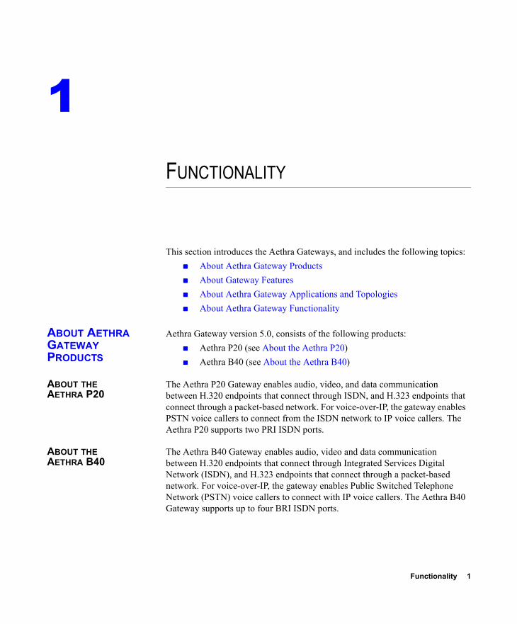
This section introduces the Aethra Gateways, and includes the following topics: About Aethra Gateway Products About Gateway Features About Aethra Gateway Applications and Topologies About Aethra Gateway Functionality
ABOUT AETHRA GATEWAY PRODUCTS
Aethra Gateway version 5.0, consists of the following products: Aethra P20 (see About the Aethra P20) Aethra B40 (see About the Aethra B40)
ABOUT THE AETHRA P20
The Aethra P20 Gateway enables audio, video, and data communication between H.320 endpoints that connect through ISDN, and H.323 endpoints that connect through a packet-based network. For voice-over-IP, the gateway enables PSTN voice callers to connect from the ISDN network to IP voice callers. The Aethra P20 supports two PRI ISDN ports.
ABOUT THE AETHRA B40
The Aethra B40 Gateway enables audio, video and data communication between H.320 endpoints that connect through Integrated Services Digital Network (ISDN), and H.323 endpoints that connect through a packet-based network. For voice-over-IP, the gateway enables Public Switched Telephone Network (PSTN) voice callers to connect with IP voice callers. The Aethra B40 Gateway supports up to four BRI ISDN ports.

2 Aethra Gateway User Guide
About Gateway Features
ABOUT GATEWAY FEATURES
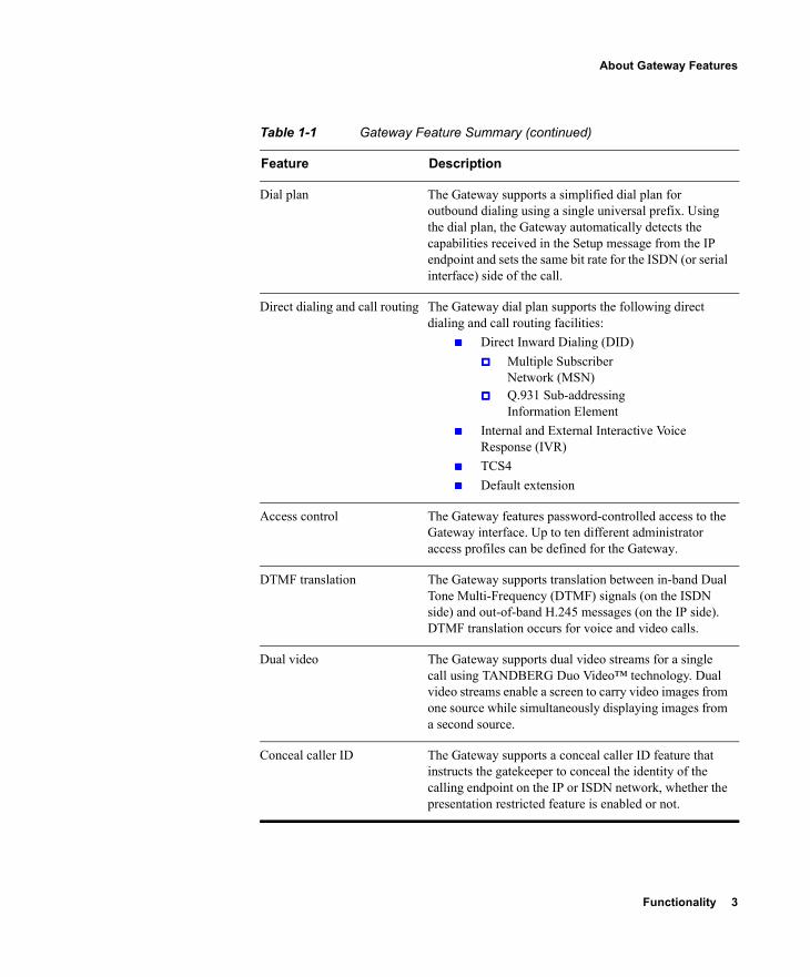
Table 1-1 lists the major features of the Aethra Gateways.
Table 1-1 Gateway Feature Summary
Feature Description
Interoperability The Gateway provides a high degree of interoperability with other H.323 compliant gateways, gatekeepers, terminals, proxy, and Multipoint Control Unit (MCU) products by being based on the H.320 standard and H.323 protocol stack.
Web-based management The Gateway features the Gateway interface. This is a web interface used to configure and monitor the Gateway. You can view and modify all aspects of the Gateway configuration from a remote location using a Java-enabled web browser.
SNMP management The Gateway features Simple Network Management Protocol (SNMP) management that supports all aspects of monitoring, diagnostics, configuration, and trapping.
Diagnostics The Gateway features front and rear panel LED indicators that display status for the unit. You can also access remote diagnostics of the unit through the Gateway interface, Telnet, SNMP, or a serial port.
Network load balancing The Gateway supports load balancing on the network by communicating with a gatekeeper through H.323 RAI (Resource Available Indication)/RAC (Resource Available Confirmation) messages.
T.120 data collaboration The Gateway supports data transfers in calls between ISDN and IP by using high speed T.120 in HMLP and VarMLP formats.
Quality of service (QoS) The Gateway features configurable coding of media packets to achieve QoS routing priority on the Internet Protocol (IP) network. The Type of Service (ToS) bits of the IP datagram header can be configured for priority level.
Functionality 3
About Gateway Features
Dial plan The Gateway supports a simplified dial plan for outbound dialing using a single universal prefix. Using the dial plan, the Gateway automatically detects the capabilities received in the Setup message from the IP endpoint and sets the same bit rate for the ISDN (or serial interface) side of the call.
Direct dialing and call routing The Gateway dial plan supports the following direct dialing and call routing facilities:
Direct Inward Dialing (DID) Multiple Subscriber
Network (MSN) Q.931 Sub-addressing
Information Element Internal and External Interactive Voice
Response (IVR) TCS4 Default extension
Access control The Gateway features password-controlled access to the Gateway interface. Up to ten different administrator access profiles can be defined for the Gateway.
DTMF translation The Gateway supports translation between in-band Dual Tone Multi-Frequency (DTMF) signals (on the ISDN side) and out-of-band H.245 messages (on the IP side). DTMF translation occurs for voice and video calls.
Dual video The Gateway supports dual video streams for a single call using TANDBERG Duo Video™ technology. Dual video streams enable a screen to carry video images from one source while simultaneously displaying images from a second source.
Conceal caller ID The Gateway supports a conceal caller ID feature that instructs the gatekeeper to conceal the identity of the calling endpoint on the IP or ISDN network, whether the presentation restricted feature is enabled or not.
Table 1-1 Gateway Feature Summary (continued)
Feature Description
4 Aethra Gateway User Guide
About Gateway Features
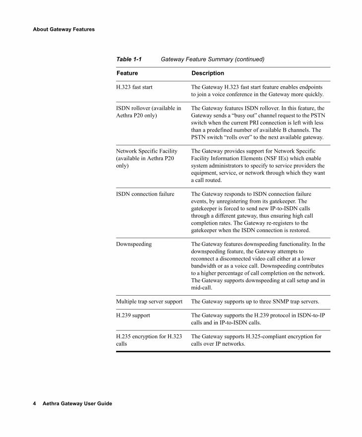
H.323 fast start The Gateway H.323 fast start feature enables endpoints to join a voice conference in the Gateway more quickly.
ISDN rollover (available in Aethra P20 only)
The Gateway features ISDN rollover. In this feature, the Gateway sends a “busy out” channel request to the PSTN switch when the current PRI connection is left with less than a predefined number of available B channels. The PSTN switch “rolls over” to the next available gateway.
Network Specific Facility (available in Aethra P20 only)
The Gateway provides support for Network Specific Facility Information Elements (NSF IEs) which enable system administrators to specify to service providers the equipment, service, or network through which they want a call routed.
ISDN connection failure The Gateway responds to ISDN connection failure events, by unregistering from its gatekeeper. The gatekeeper is forced to send new IP-to-ISDN calls through a different gateway, thus ensuring high call completion rates. The Gateway re-registers to the gatekeeper when the ISDN connection is restored.
Downspeeding The Gateway features downspeeding functionality. In the downspeeding feature, the Gateway attempts to reconnect a disconnected video call either at a lower bandwidth or as a voice call. Downspeeding contributes to a higher percentage of call completion on the network. The Gateway supports downspeeding at call setup and in mid-call.
Multiple trap server support The Gateway supports up to three SNMP trap servers.
H.239 support The Gateway supports the H.239 protocol in ISDN-to-IP calls and in IP-to-ISDN calls.
H.235 encryption for H.323 calls
The Gateway supports H.325-compliant encryption for calls over IP networks.
Table 1-1 Gateway Feature Summary (continued)
Feature Description
Functionality 5
About Gateway Features
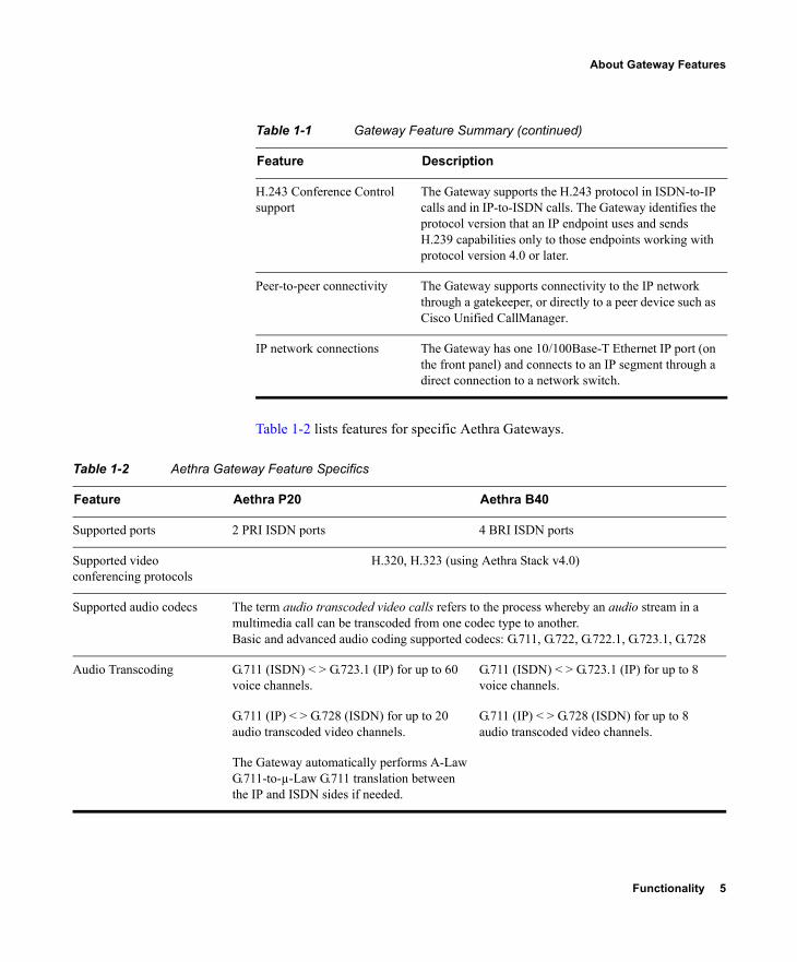
Table 1-2 lists features for specific Aethra Gateways.
H.243 Conference Control support
The Gateway supports the H.243 protocol in ISDN-to-IP calls and in IP-to-ISDN calls. The Gateway identifies the protocol version that an IP endpoint uses and sends H.239 capabilities only to those endpoints working with protocol version 4.0 or later.
Peer-to-peer connectivity The Gateway supports connectivity to the IP network through a gatekeeper, or directly to a peer device such as Cisco Unified CallManager.
IP network connections The Gateway has one 10/100Base-T Ethernet IP port (on the front panel) and connects to an IP segment through a direct connection to a network switch.
Table 1-1 Gateway Feature Summary (continued)
Feature Description
Table 1-2 Aethra Gateway Feature Specifics
Feature Aethra P20 Aethra B40
Supported ports 2 PRI ISDN ports 4 BRI ISDN ports
Supported video conferencing protocols
H.320, H.323 (using Aethra Stack v4.0)
Supported audio codecs The term audio transcoded video calls refers to the process whereby an audio stream in a multimedia call can be transcoded from one codec type to another.Basic and advanced audio coding supported codecs: G.711, G.722, G.722.1, G.723.1, G.728
Audio Transcoding G.711 (ISDN) < > G.723.1 (IP) for up to 60 voice channels.
G.711 (ISDN) < > G.723.1 (IP) for up to 8 voice channels.
G.711 (IP) < > G.728 (ISDN) for up to 20 audio transcoded video channels.
G.711 (IP) < > G.728 (ISDN) for up to 8 audio transcoded video channels.
The Gateway automatically performs A-Law G.711-to-µ-Law G.711 translation between the IP and ISDN sides if needed.

6 Aethra Gateway User Guide
About Gateway Features
Note When your Aethra unit includes both a Gateway and an MCU, G.728 transcoding is supported on the MCU only.
Supported video protocols H.261, H.263, H.263+ (Annexes F, J and N), H.263++ (Annex W), H.264
Supported video resolutions VGA, XGA, SVGA, SIF, 4SIF, CIF, QCIF, 4CIF, 16CIF
Supported bandwidths (Kbps)
56, 64, 112, 128, 168, 192, 224, 256, 280, 320, 336, 384, 448, 512, 672, 768, 1288, 1472, 1680 and 1920
56, 64, 112, 128, 224, 256, 336, 384 and 512
Note Bandwidth rates of 256 Kbps and up support the G.722 audio codec.
Call handling capabilities For 1 x PRI T1 line:23 ports (voice)23 ports 1B (video and data)11 ports 2B (video and data)3 ports 6B (video and data)For 2 x PRI T1 lines:46 ports (voice)30 ports 1B (video and data)23 ports 2B (video and data)7 ports 6B (video and data)For 1 x PRI E1 line:30 ports (voice)30 ports 1B (video and data)15 ports 2B (video and data)5 ports 6B (video and data)For 2 x PRI E1 lines: 60 ports (voice)30 ports 1B/2B (video and data)10 ports 6B (video and data)
For 4 x BRI lines:8 voice-only calls or 8 video calls or any combination of the two:1 call x 512 Kbps1 call x 384 Kbps +2 calls x 256 Kbps4 calls x 128 Kbps8 calls x 64 Kbps
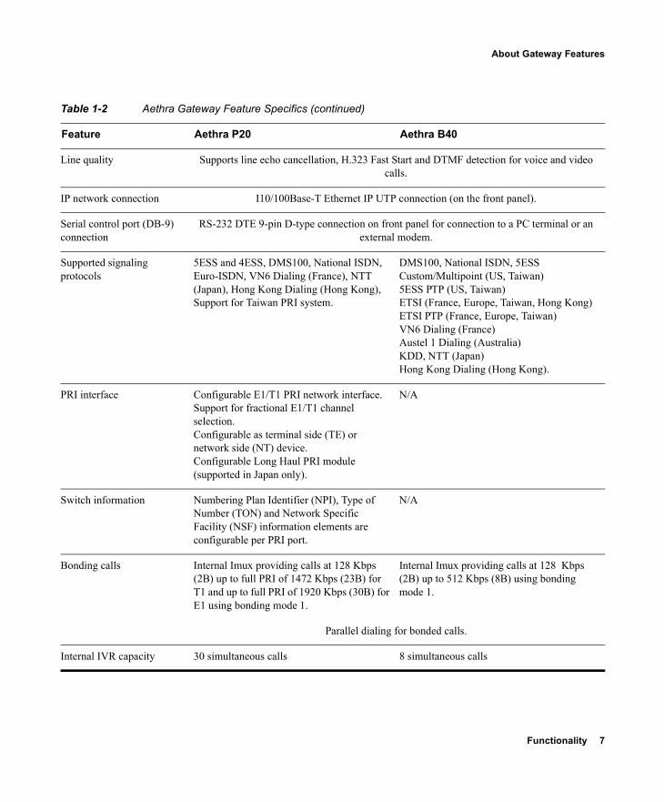
Table 1-2 Aethra Gateway Feature Specifics (continued)
Feature Aethra P20 Aethra B40
Functionality 7
About Gateway Features
Line quality Supports line echo cancellation, H.323 Fast Start and DTMF detection for voice and video calls.
IP network connection I10/100Base-T Ethernet IP UTP connection (on the front panel).
Serial control port (DB-9) connection
RS-232 DTE 9-pin D-type connection on front panel for connection to a PC terminal or an external modem.
Supported signaling protocols
5ESS and 4ESS, DMS100, National ISDN, Euro-ISDN, VN6 Dialing (France), NTT (Japan), Hong Kong Dialing (Hong Kong), Support for Taiwan PRI system.
DMS100, National ISDN, 5ESS Custom/Multipoint (US, Taiwan)5ESS PTP (US, Taiwan)ETSI (France, Europe, Taiwan, Hong Kong)ETSI PTP (France, Europe, Taiwan)VN6 Dialing (France)Austel 1 Dialing (Australia)KDD, NTT (Japan)Hong Kong Dialing (Hong Kong).
PRI interface Configurable E1/T1 PRI network interface.Support for fractional E1/T1 channel selection.Configurable as terminal side (TE) or network side (NT) device.Configurable Long Haul PRI module (supported in Japan only).
N/A
Switch information Numbering Plan Identifier (NPI), Type of Number (TON) and Network Specific Facility (NSF) information elements are configurable per PRI port.
N/A
Bonding calls Internal Imux providing calls at 128 Kbps (2B) up to full PRI of 1472 Kbps (23B) for T1 and up to full PRI of 1920 Kbps (30B) for E1 using bonding mode 1.
Internal Imux providing calls at 128 Kbps (2B) up to 512 Kbps (8B) using bonding mode 1.
Parallel dialing for bonded calls.
Internal IVR capacity 30 simultaneous calls 8 simultaneous calls
Table 1-2 Aethra Gateway Feature Specifics (continued)
Feature Aethra P20 Aethra B40
8 Aethra Gateway User Guide
About Aethra Gateway Applications and Topologies
ABOUT AETHRA GATEWAY APPLICATIONS AND TOPOLOGIES
The Aethra Gateway supports multimedia conferencing by translating between H.323 and H.320 protocols. Examples of network applications that use the Gateway include:
Multimedia conferencing (see About Multimedia Conferencing on page 8)
Point-to-Point conferencing (see About Point-to-Point Conferencing on page 10)
Multipoint conferencing (see About Multipoint Conferencing on page 10)
IP networking (see About Gateway IP Network Connections on page 11)
ISDN networking (see About Gateway ISDN Network Connections on page 11)
ABOUT MULTIMEDIA CONFERENCING
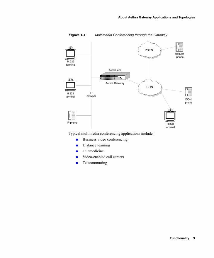
The Aethra PRI gateway and BRI Gateway enable H.323 endpoints on the IP network to communicate with an H.320 terminal, an ISDN phone, or a regular phone on a circuit-switched public network without having to connect directly to these networks. The Gateway allows all IP network terminals to support video conferences without connecting every desktop computer to an ISDN line (see Figure 1-1).
Functionality 9
About Aethra Gateway Applications and Topologies
Figure 1-1 Multimedia Conferencing through the Gateway
Typical multimedia conferencing applications include: Business video conferencing Distance learning Telemedicine Video-enabled call centers Telecommuting
IP phone
H.323 terminal
ISDN
ISDNphone
Regularphone
PSTN
Aethra unit
Aethra Gateway
IPnetwork
H.323 terminal
H.320 terminal
10 Aethra Gateway User Guide
About Aethra Gateway Applications and Topologies
ABOUT POINT-TO-POINT CONFERENCING
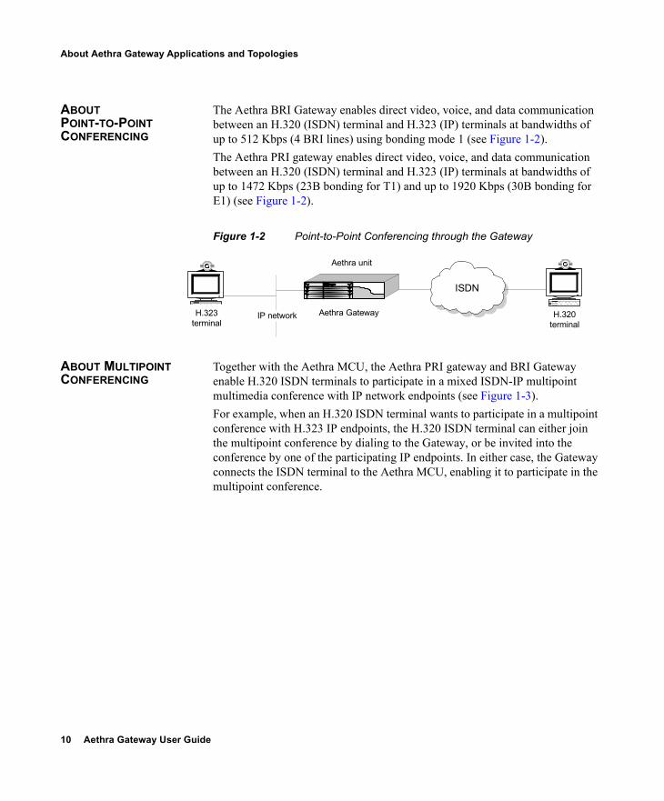
The Aethra BRI Gateway enables direct video, voice, and data communication between an H.320 (ISDN) terminal and H.323 (IP) terminals at bandwidths of up to 512 Kbps (4 BRI lines) using bonding mode 1 (see Figure 1-2).The Aethra PRI gateway enables direct video, voice, and data communication between an H.320 (ISDN) terminal and H.323 (IP) terminals at bandwidths of up to 1472 Kbps (23B bonding for T1) and up to 1920 Kbps (30B bonding for E1) (see Figure 1-2).
Figure 1-2 Point-to-Point Conferencing through the Gateway
ABOUT MULTIPOINT CONFERENCING
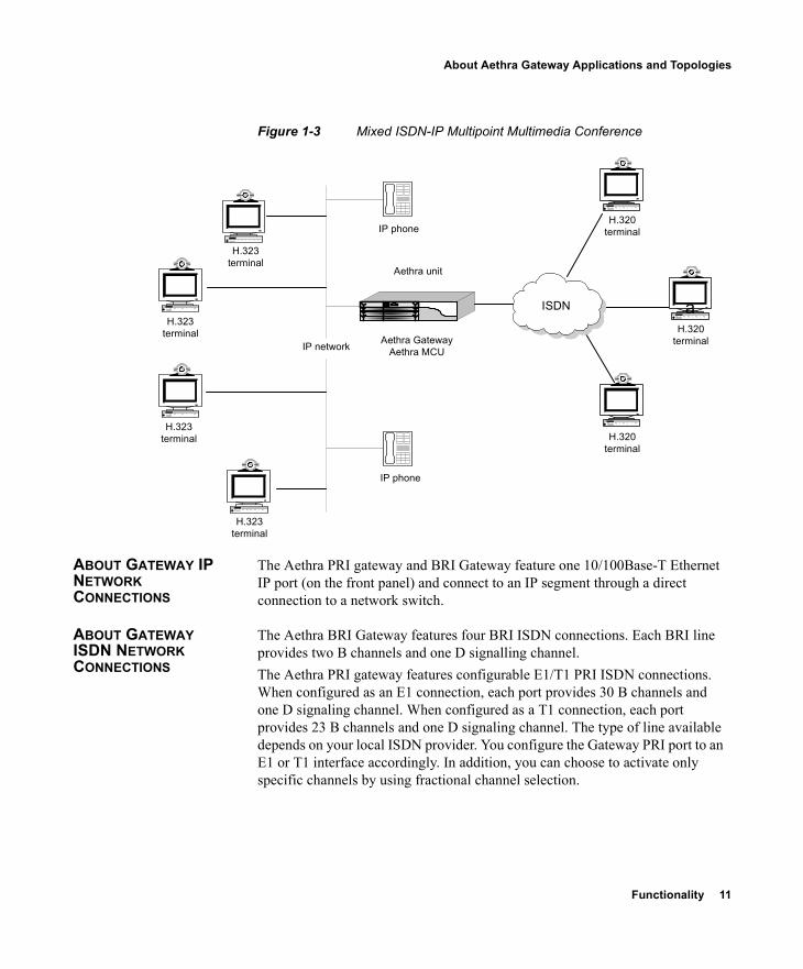
Together with the Aethra MCU, the Aethra PRI gateway and BRI Gateway enable H.320 ISDN terminals to participate in a mixed ISDN-IP multipoint multimedia conference with IP network endpoints (see Figure 1-3).For example, when an H.320 ISDN terminal wants to participate in a multipoint conference with H.323 IP endpoints, the H.320 ISDN terminal can either join the multipoint conference by dialing to the Gateway, or be invited into the conference by one of the participating IP endpoints. In either case, the Gateway connects the ISDN terminal to the Aethra MCU, enabling it to participate in the multipoint conference.
IP network
Aethra unit
Aethra Gateway
ISDN
H.323 terminal
H.320 terminal
Functionality 11
About Aethra Gateway Applications and Topologies
Figure 1-3 Mixed ISDN-IP Multipoint Multimedia Conference
ABOUT GATEWAY IP NETWORK CONNECTIONS
The Aethra PRI gateway and BRI Gateway feature one 10/100Base-T Ethernet IP port (on the front panel) and connect to an IP segment through a direct connection to a network switch.
ABOUT GATEWAY ISDN NETWORK CONNECTIONS
The Aethra BRI Gateway features four BRI ISDN connections. Each BRI line provides two B channels and one D signalling channel.The Aethra PRI gateway features configurable E1/T1 PRI ISDN connections. When configured as an E1 connection, each port provides 30 B channels and one D signaling channel. When configured as a T1 connection, each port provides 23 B channels and one D signaling channel. The type of line available depends on your local ISDN provider. You configure the Gateway PRI port to an E1 or T1 interface accordingly. In addition, you can choose to activate only specific channels by using fractional channel selection.
IP network
IP phone
ISDN
Aethra unit
Aethra GatewayAethra MCU
IP phone
H.323 terminal
aH.323
terminal
H.323 terminal
H.323 terminal
H.320 terminal
H.320 terminal
H.320 terminal
12 Aethra Gateway User Guide
About Aethra Gateway Applications and Topologies
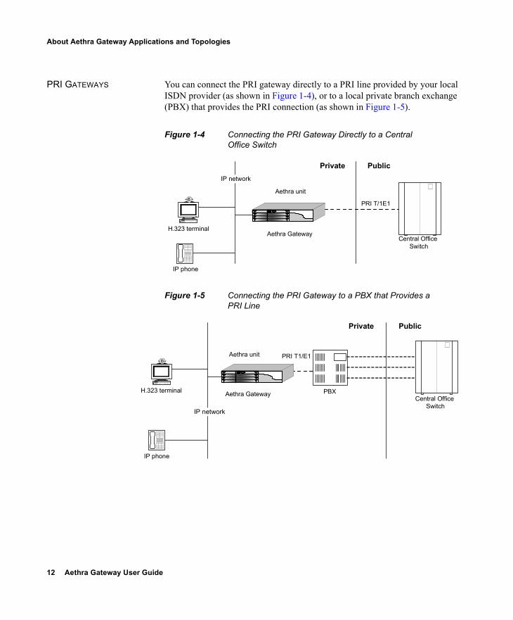
PRI GATEWAYS You can connect the PRI gateway directly to a PRI line provided by your local ISDN provider (as shown in Figure 1-4), or to a local private branch exchange (PBX) that provides the PRI connection (as shown in Figure 1-5).
Figure 1-4 Connecting the PRI Gateway Directly to a Central Office Switch
Figure 1-5 Connecting the PRI Gateway to a PBX that Provides a PRI Line
PRI T 1/ E1
Central OfficeSwitch
Private Public
H.323 terminal
Aethra unit
Aethra Gateway
IP phone
IP network
PRI T1/E1
Central OfficeSwitch
Private Public
H.323 terminal
IP phone
Aethra Gateway
Aethra unit
IP network
PBX

Functionality 13
About Aethra Gateway Applications and Topologies
BRI GATEWAYS You can connect the BRI Gateway to a local private branch exchange (PBX) that provides the BRI connection (as shown in Figure 1-6), or to a public phone network using an NT1 device (as shown in Figure 1-7).
Figure 1-6 Connecting the BRI Gateway Directly to a PBX that Provides a BRI Line
Figure 1-7 Connecting the BRI Gateway Directly to a Central Office Switch
BRI
Central OfficeSwitch
Private Public
H.323 terminal
IP phone
Aethra Gateway
Aethra unit
IP network
PBX
BRI
Central Office Switch
Private Public
H.323 terminal
Aethra unit
Aethra Gateway
IP phone
IP network
NT1 device
14 Aethra Gateway User Guide
About Aethra Gateway Functionality
ABOUT AETHRA GATEWAY FUNCTIONALITY
This section discusses the following topics: About PRI Gateway Call Handling Capacity on page 14 About Gateway Call Bandwidth Overhead on page 15 About Peer-to-Peer Connectivity on page 16
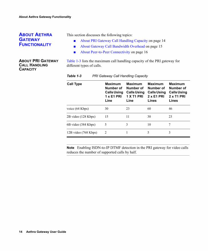
ABOUT PRI GATEWAY CALL HANDLING CAPACITY
Table 1-3 lists the maximum call handling capacity of the PRI gateway for different types of calls.
Note Enabling ISDN-to-IP DTMF detection in the PRI gateway for video calls reduces the number of supported calls by half.
Table 1-3 PRI Gateway Call Handling Capacity
Call Type Maximum Number of Calls Using 1 x E1 PRI Line
Maximum Number of Calls Using 1 X T1 PRI Line
Maximum Number of Calls Using 2 x E1 PRI Lines
Maximum Number of Calls Using 2 x T1 PRI Lines
voice (64 Kbps) 30 23 60 46
2B video (128 Kbps) 15 11 30 23
6B video (384 Kbps) 5 3 10 7
12B video (768 Kbps) 2 1 5 3
Functionality 15
About Aethra Gateway Functionality
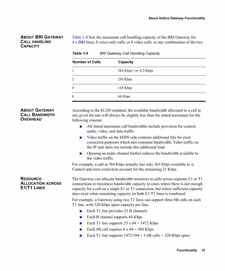
ABOUT BRI GATEWAY CALL HANDLING CAPACITY
Table 1-4 lists the maximum call handling capacity of the BRI Gateway for 4 x BRI lines, 8 voice-only calls, or 8 video calls, or any combination of the two.
ABOUT GATEWAY CALL BANDWIDTH OVERHEAD
According to the H.320 standard, the available bandwidth allocated to a call at any given bit rate will always be slightly less than the stated maximum for the following reasons:
All stated maximum call bandwidths include provision for control, audio, video, and data traffic.
Video traffic on the ISDN side contains additional bits for error correction purposes which also consume bandwidth. Video traffic on the IP side does not include this additional load.
Opening an audio channel further reduces the bandwidth available to the video traffic.
For example, a call at 384 Kbps actually has only 363 Kbps available to it. Control and error correction account for the remaining 21 Kbps.
RESOURCE ALLOCATION ACROSS E1/T1 LINES
The Gateway can allocate bandwidth resources to calls across separate E1 or T1 connections to maximize bandwidth capacity in cases where there is not enough capacity for a call on a single E1 or T1 connection, but where sufficient capacity does exist when remaining capacity on both E1/T1 lines is combined. For example, a Gateway using two T1 lines can support three 6B calls on each T1 line, with 320 Kbps spare capacity per line:
Each T1 line provides 23 B channels. Each B channel supports 64 Kbps Each T1 line supports 23 x 64 = 1472 Kbps Each 6B call requires 6 x 64 = 384 Kbps Each T1 line supports 1472/384 = 3 6B calls + 320 Kbps spare
Table 1-4 BRI Gateway Call Handling Capacity
Number of Calls Capacity
1 384 Kbps+ or 412 Kbps
2 256 Kbps
4 128 Kbps
8 64 Kbps
16 Aethra Gateway User Guide
About Aethra Gateway Functionality
The Gateway processes an additional 6B call requiring a further 384 Kbps by taking bandwidth resources from each of the two T1 lines, both of which have 320 Kbps available. In this way, the Gateway spreads the call over both T1 lines.
ABOUT PEER-TO-PEER CONNECTIVITY
The Gateway supports the following types of connectivity to the IP network Through a gatekeeper Directly to a peer device such as Cisco Unified CallManager without
the need for a gatekeeper.
Setting Up Your Aethra Gateway 17
2SETTING UP YOUR AETHRA GATEWAY
This section introduces the Aethra MCU solution and details the components that Aethra MCU includes, and includes the following topics:
Physical Description Preparing for Installation Verifying the Package Contents Mounting the Aethra Gateway Unit in a 19-inch Rack Aethra Gateway Unit Initial Configuration Connecting the Aethra Gateway Unit to the LAN Managing and Monitoring the Aethra Gateway Unit Accessing the Aethra Gateway Administrator Interface Registering the Online Help
18 Aethra Gateway User Guide
Physical Description
PHYSICAL DESCRIPTION
This section provides a physical description of the Aethra Gateway units.
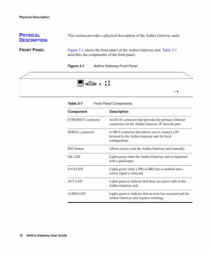
FRONT PANEL Figure 2-1 shows the front panel of the Aethra Gateway unit. Table 2-1 describes the components of the front panel.
Figure 2-1 Aethra Gateway Front Panel
Table 2-1 Front Panel Components
Component Description
ETHERNET connector An RJ-45 connector that provides the primary Ethernet connection for the Aethra Gateway IP network port.
SERIAL connector A DB-9 connector that allows you to connect a PC terminal to the Aethra Gateway unit for local configuration.
RST button Allows you to reset the Aethra Gateway unit manually.
GK LED Lights green when the Aethra Gateway unit is registered with a gatekeeper.
D-Ch LED Lights green when a PRI or BRI line is enabled and a carrier signal is detected
ACT LED Lights green to indicate that there are active calls in the Aethra Gateway unit.
ALRM LED Lights green to indicate that an error has occurred and the Aethra Gateway unit requires resetting.
Setting Up Your Aethra Gateway 19
Physical Description
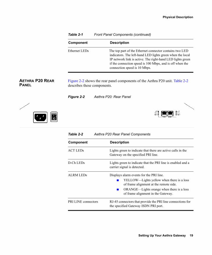
AETHRA P20 REAR PANEL
Figure 2-2 shows the rear panel components of the Aethra P20 unit. Table 2-2 describes these components.
Figure 2-2 Aethra P20: Rear Panel
Ethernet LEDs The top part of the Ethernet connector contains two LED indicators. The left-hand LED lights green when the local IP network link is active. The right-hand LED lights green if the connection speed is 100 Mbps, and is off when the connection speed is 10 Mbps.
Table 2-1 Front Panel Components (continued)
Component Description
Table 2-2 Aethra P20 Rear Panel Components
Component Description
ACT LEDs Lights green to indicate that there are active calls in the Gateway on the specified PRI line.
D-Ch LEDs Lights green to indicate that the PRI line is enabled and a carrier signal is detected.
ALRM LEDs Displays alarm events for the PRI line. YELLOW—Lights yellow when there is a loss
of frame alignment at the remote side. ORANGE—Lights orange when there is a loss
of frame alignment in the Gateway.
PRI LINE connectors RJ-45 connectors that provide the PRI line connections for the specified Gateway ISDN PRI port.
20 Aethra Gateway User Guide
Preparing for Installation
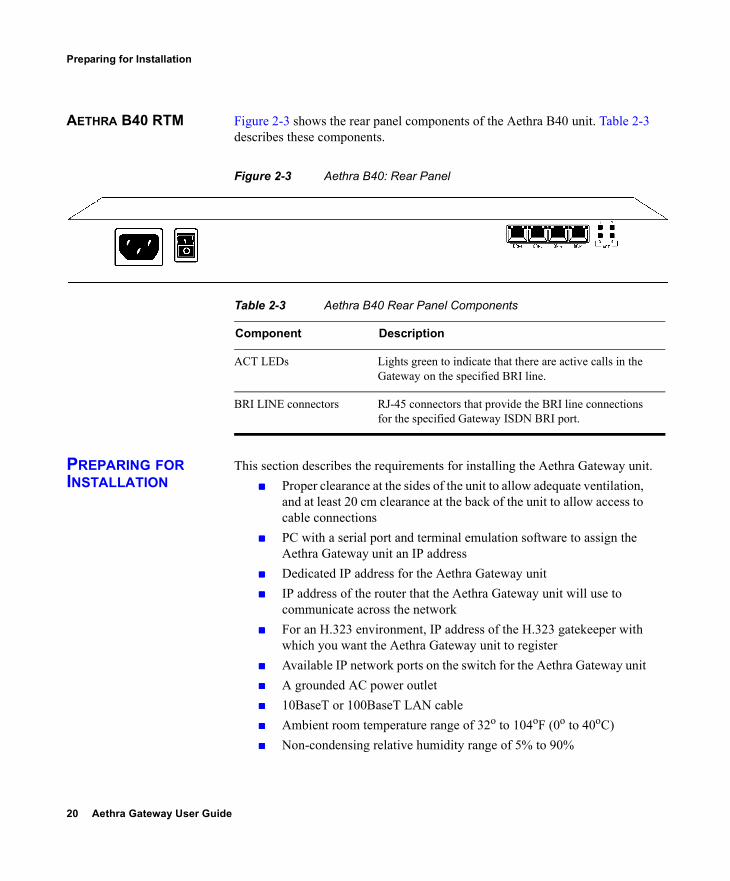
AETHRA B40 RTM Figure 2-3 shows the rear panel components of the Aethra B40 unit. Table 2-3 describes these components.
Figure 2-3 Aethra B40: Rear Panel
PREPARING FOR INSTALLATION
This section describes the requirements for installing the Aethra Gateway unit. Proper clearance at the sides of the unit to allow adequate ventilation,
and at least 20 cm clearance at the back of the unit to allow access to cable connections
PC with a serial port and terminal emulation software to assign the Aethra Gateway unit an IP address
Dedicated IP address for the Aethra Gateway unit IP address of the router that the Aethra Gateway unit will use to
communicate across the network For an H.323 environment, IP address of the H.323 gatekeeper with
which you want the Aethra Gateway unit to register Available IP network ports on the switch for the Aethra Gateway unit A grounded AC power outlet 10BaseT or 100BaseT LAN cable Ambient room temperature range of 32o to 104oF (0o to 40oC) Non-condensing relative humidity range of 5% to 90%
Table 2-3 Aethra B40 Rear Panel Components
Component Description
ACT LEDs Lights green to indicate that there are active calls in the Gateway on the specified BRI line.
BRI LINE connectors RJ-45 connectors that provide the BRI line connections for the specified Gateway ISDN BRI port.
Setting Up Your Aethra Gateway 21
Verifying the Package Contents
VERIFYING THE PACKAGE CONTENTS
Inspect the contents of the box for shipping damage. Report any damage or missing items to your distributor or reseller. Table 2-4 lists the package contents for the Aethra Gateway unit.
MOUNTING THE AETHRA GATEWAY UNIT IN A 19-INCH RACK
You can optionally mount the Aethra Gateway unit in a standard 19-inch rack. Two mounting brackets and a set of screws are included in the Aethra Gateway unit shipping box.
Procedure
1 Disconnect all cables including the power cables.2 Place the Aethra Gateway unit right-side up on a hard flat
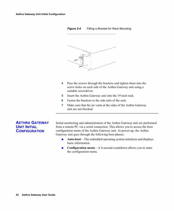
surface, with the front panel facing you.3 Position a mounting bracket over the mounting holes on each
side of the Aethra Gateway unit, as shown in Figure 2-4.
Table 2-4 Package Contents with Aethra Gateway Unit
Product Contents
Aethra P20 or Aethra B40 unit
Aethra Gateway Unit Power cable (depending on customer location) Terminal cable LAN cable Rack mounting kit (two brackets and six screws) Four rubber feet Aethra Gateway User Guide (in PDF format only) Aethra Gateway Quick Start Aethra Gateway Release Notes Utilities and Documentation CD-ROM containing
product documentation, utilities and online help files.
22 Aethra Gateway User Guide
Aethra Gateway Unit Initial Configuration
Figure 2-4 Fitting a Bracket for Rack Mounting
4 Pass the screws through the brackets and tighten them into the screw holes on each side of the Aethra Gateway unit using a suitable screwdriver.
5 Insert the Aethra Gateway unit into the 19-inch rack.6 Fasten the brackets to the side rails of the rack.7 Make sure that the air vents at the sides of the Aethra Gateway
unit are not blocked.
AETHRA GATEWAY UNIT INITIAL CONFIGURATION
Initial monitoring and administration of the Aethra Gateway unit are performed from a remote PC via a serial connection. This allows you to access the boot configuration menu of the Aethra Gateway unit. At power-up, the Aethra Gateway unit goes through the following boot phases:
Auto-boot—The embedded operating system initializes and displays basic information.
Configuration menu—A 6-second countdown allows you to enter the configuration menu.

Setting Up Your Aethra Gateway 23
Aethra Gateway Unit Initial Configuration
Initialization—The Aethra Gateway unit completes its boot sequence and is ready for operation.
Note You can perform serial port configuration of the Aethra Gateway unit only at startup, during a short period indicated by a 6-second countdown. Once the initialization phase is complete, the only way you can access the configuration menu is by restarting the Aethra Gateway unit.
CONNECTING TO A PC This section describes how to use the serial port connection to configure the Aethra Gateway unit with an IP address.
Procedure
1 Locate the terminal cable shipped with the Aethra Gateway unit.
2 Connect the end labeled PC to the serial port on the computer.3 Connect the end labeled Unit to the serial port connector on the
Aethra Gateway unit front panel.
Note The PC terminal should have an installed terminal emulation application, such as HyperTerminal.
SETTING THE IP ADDRESS
This section describes how to use the serial port to configure the unit with an IP address and other address information.The serial port on the Aethra Gateway unit front panel is used to assign a new IP address to your Aethra Gateway unit. You must assign the IP address before you connect the Aethra Gateway unit to the network.
Before You Begin
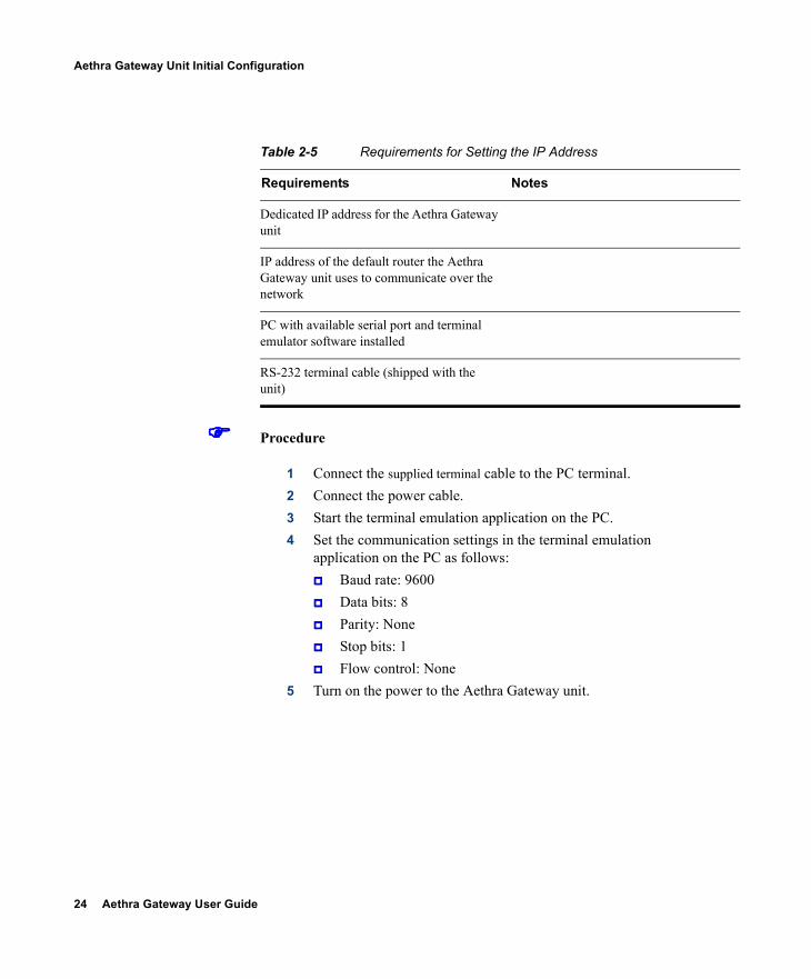
Gather the items listed in Table 2-5 to assign an IP address to the Aethra Gateway unit.
24 Aethra Gateway User Guide
Aethra Gateway Unit Initial Configuration
Procedure
1 Connect the supplied terminal cable to the PC terminal.2 Connect the power cable.3 Start the terminal emulation application on the PC.4 Set the communication settings in the terminal emulation
application on the PC as follows: Baud rate: 9600 Data bits: 8 Parity: None Stop bits: 1 Flow control: None
5 Turn on the power to the Aethra Gateway unit.
Table 2-5 Requirements for Setting the IP Address
Requirements Notes
Dedicated IP address for the Aethra Gateway unit
IP address of the default router the Aethra Gateway unit uses to communicate over the network
PC with available serial port and terminal emulator software installed
RS-232 terminal cable (shipped with the unit)

Setting Up Your Aethra Gateway 25
Aethra Gateway Unit Initial Configuration
6 After the terminal emulator session starts, press the RST button on the Aethra Gateway unit front panel to reset the module.A log of the auto-boot events and a VxWorks banner scrolls across the computer monitor.
Note When the Aethra Gateway unit is started for the first time, two VxWorks banners appear. The configuration option appears after the second banner.
7 When the message “Press any key to start configuration” appears on the screen, press any key within 6 seconds. The Network Configuration menu displays: Press any Key To start configuration...
6
Enter <N> to configure default network port values
Enter <P> to change the configuration software password
Enter <A> to display advanced configuration menu
Enter <Q> to quit configuration menu and start GW
Caution If you do not press a key before the countdown ends, the device continues its initialization and you can only configure the device by pressing the RST button on the front panel.
8 At the prompt, type N to configure default network port values and press Enter.
9 At the Enter IP address for default interface prompt, type the IP address you want to assign to the Aethra Gateway unit and press Enter.
Caution Do not use leading zeros in the IP address.

26 Aethra Gateway User Guide
Aethra Gateway Unit Initial Configuration
10 At the Enter Default Router IP Address prompt, type the IP address of the router associated with the segment in which the unit will be installed and press Enter.
Caution Do not use leading zeros in the IP address.
11 At the Enter IP Mask <HEX> for default device prompt, type the subnet mask as follows: Convert the subnet mask IP address to hexadecimal
notation, type the hexadecimal number at the prompt, and press Enter. For example, for the subnet mask 255.255.255.0 the hexadecimal value you type is FFFFFF00.
Note You can use the computer’s desktop calculator to convert the subnet mask ID to hexadecimal notation.
If a subnet mask is not used, press Enter.12 Allow the unit to complete the reboot process. A new emulator
session begins.13 Close the terminal emulator session.
CHANGING THE CONFIGURATION TOOL LOGIN PASSWORD
You can use the terminal emulator to change the default password of the default login user before others can use the Aethra Gateway interface.
Procedure
1 Start a terminal emulator session for the Aethra Gateway unit.2 Press the RST button on the front panel of the Aethra Gateway
unit.After 60 seconds, a new terminal emulator session begins on the computer monitor.
Setting Up Your Aethra Gateway 27
Connecting the Aethra Gateway Unit to the LAN
3 After the second VxWorks banner scrolls across the screen, the following message appears: “Press any Key to start the configuration.”
4 Press any key and then press Enter.The default network properties screen appears.
5 At the prompt, enter P and press Enter to select “change the configuration software password.”The “Enter user name” prompt appears.
6 Enter the user login name for which you want to change the password and press Enter. The default user name is admin. This is the user name that allows you to access the Aethra Gateway interface.The Enter new password prompt appears.
7 Enter the password you want the user to use to log in to the Gateway interface and press Enter.There is no default password.
8 The configuration menu re-appears.9 Enter Q and press Enter to exit.
CONNECTING THE AETHRA GATEWAY UNIT TO THE LAN
This section describes how to connect the Aethra Gateway unit to the Local Area Network (LAN).
Procedure
1 Connect the supplied LAN cable from your network hub to the 10/100BaseT Ethernet port on the front panel of the Aethra Gateway unit. The 10/100BaseT port accepts an RJ-45 connector.
2 Connect a separate ISDN or serial line to each PRI or BRI port in the rear panel of the Aethra Gateway unit. The port accepts an RJ-45 connector.
28 Aethra Gateway User Guide
Managing and Monitoring the Aethra Gateway Unit
MANAGING AND MONITORING THE AETHRA GATEWAY UNIT
You can manage and monitor the Aethra Gateway unit locally or from remote connections. You can also upgrade Aethra Gateway software.
SNMP MANAGEMENT The Aethra Gateway unit is equipped with an SNMP agent. You can access the Aethra Gateway unit using an SNMP management client.
LOCAL PORT MONITORING CONNECTIONS
You should access the Aethra Gateway unit using a local port connection for preliminary configuration and monitoring.
SERIAL PORT The Aethra Gateway unit includes a DB-9 serial port connector and an RJ-45 serial port connector. The DB-9 serial port is used to access the boot sequence menu from a local PC. Using a terminal emulation application running on the PC, you can assign an IP address and subnet mask to the Aethra Gateway unit. The RJ-45 serial port is used to connect a PC terminal to the Aethra Gateway unit.
Note A special adapter cable for connecting between a standard DB-9 serial cable and the RJ-45 serial port is supplied with the Aethra Gateway unit.
SVGA PORT The Aethra Gateway unit is equipped with an SVGA port for connecting to a standard PC monitor screen. The SVGA port allows you to view the operating system desktop and to monitor the applications that are active on the desktop.
PERFORMING SOFTWARE UPGRADES
You can perform software upgrades by using the Aethra Upgrade Utility to upload files via a network or modem connection to the Aethra Gateway unit. For more information, see the Using the Aethra Software Upgrade Utility chapter.
Setting Up Your Aethra Gateway 29
Accessing the Aethra Gateway Administrator Interface
ACCESSING THE AETHRA GATEWAY ADMINISTRATOR INTERFACE
The Aethra Gateway Administrator is a web interface that allows you to configure general Aethra Gateway unit settings, monitor Aethra Gateway unit operation, create or edit services and perform maintenance.You access the Aethra Gateway Administrator web interface in the Aethra Gateway unit access window by signing in as an Administrator.You can use your web browser from any remote PC station to monitor and to configure the Aethra Gateway unit. A web server is installed in the Aethra Gateway unit to facilitate the use of the remote web-based monitoring and management.Access to the Aethra Gateway configuration interface is controlled by a user name and a password. Once you have entered the settings you want, you should upload them to the unit for them to take effect, or you can save them to a configuration file to be loaded at a later time.
Before You Begin
The following requirements are necessary to access the Gateway Administrator web interface:
A Java-compliant browser. Microsoft Internet Explorer version 5.5 or later is recommended.
The Aethra Gateway unit IP address or a web link to the Aethra Gateway unit.
Administrator level-access The required user name and password.
Note For first-time installation, you must assign an IP address to the Aethra Gateway unit using a serial port connection before you can access the web interface. For more information, see Setting the IP Address on page 23.
Procedure
1 Launch your browser and type the IP address or the name of the Aethra Gateway unit.For example, http://125.221.23.44 or board_name.The Aethra Gateway login page appears.
30 Aethra Gateway User Guide
Registering the Online Help
2 Type the Administrator user name and password in the appropriate fields and click Login. The default global user name is admin. The default password is <null>.The Gateway Administrator interface appears.
Note If you try to sign in as an Administrator and another Administrator is currently signed in, the Aethra Gateway signs you in as a Read only user and the words Read Only appear at the top of the window. Read only users cannot edit any of the Aethra Gateway settings.
REGISTERING THE ONLINE HELP
The online help files for the Aethra Gateway Administrator interface are shipped on the Aethra Utilities and Documentation CD-ROM. To use the online help, you must install the help files for the appropriate Gateway in a shared directory on your network and register the directory location in the Administrator interface.
Procedure
1 Ensure that you have installed the online help library from the Aethra Utilities and Documentation CD-ROM on your PC.
2 Open a Java-compliant web browser and access the Aethra Gateway Administrator web interface. The Administrator login page appears.
3 In the Name field, type you user name.4 In the Password field, type your password.5 Click Go.6 On the sidebar, click Device. 7 Click the Web tab.8 In the Online Help URL field, type the path to the directory in
which the MCU online help files that you want to use are stored as follows: If the directory is located on a file server, type:
file://.../shared_directory_name /program_folder
Setting Up Your Aethra Gateway 31
Registering the Online Help
If the directory is located on a web server, type:http://.../shared_directory_name /program_folder
9 On the toolbar, click Upload.
NETSCAPE NAVIGATOR USERS
Online help files located on the local network and accessed using Netscape Navigator 4.x must be located on a mapped network drive.

Configuring the Aethra Gateway 33
3CONFIGURING THE AETHRA GATEWAY
This section describes what you can configure and how to configure Aethra Gateways, and includes the following topics:
About Gateway Interface Users Viewing LED Information Viewing General Information About the Gateway Viewing Address Settings Changing the Administrator Interface Web Server Port Configuring Security About the Gateway Administrator Interface Viewing the Status Tab Configuring Gateway Settings About Gateway Services Configuring Port Settings Viewing Call Information Viewing Gateway Alarm Events Viewing Gateway Statistics Configuring Gateway Maintenance Tasks Saving Configuration Settings Importing Configuration Files
34 Aethra Gateway User Guide
About Gateway Interface Users
ABOUT GATEWAY INTERFACE USERS
Users must have the appropriate access level to log in to the Gateway interface. With Administrator-level access, a user can configure the Gateway and monitor Gateway activity. You can view and manage the list of Gateway users in the Users tab of the Device section of the Gateway interface. The Users tab displays all currently configured users and their access levels.There are three types of Gateway interface users:
Administrator—Full access to the Gateway interface to configure Gateway settings.
Operator—User can monitor or disconnect calls but otherwise only has read-only access to the Gateway interface.
Read-only—User has read-only access to the Gateway interface.
ADDING GATEWAY INTERFACE USERS
In the Users tab of the Device section of the Gateway interface, you can add Gateway interface users.
Procedure
1 In the Gateway interface, on the sidebar, click Device.2 Click the Users tab.3 Click Add to add a new user.
The Add User dialog box appears.4 In the User name field, enter the user login name.5 In the Access Level field, choose one of the following access
levels: Administrator, Operator or Read only.6 In the Password field, enter the password that the user uses to
login to the Gateway interface.7 In the Confirm Password field, re-enter the password.8 Click Upload.
EDITING GATEWAY INTERFACE USERS
In the Users tab of the Device section of the Gateway interface, you can edit Gateway interface users.
Procedure
1 In the Gateway interface, on the sidebar, click Device.2 Click the Users tab.
Configuring the Aethra Gateway 35
Viewing LED Information
3 Select an existing user and click Edit.The Edit User dialog box appears.
4 In the User name field, edit the user login name.5 In the Access Level field, choose one of the following access
levels: Administrator, Operator or Read only.6 In the Password field, edit the password that the user uses to
login to the Gateway interface.7 In the Confirm Password field, re-enter the password.8 Click Upload.
DELETING GATEWAY INTERFACE USERS
In the Users tab of the Device section of the Gateway interface, you can delete Gateway interface users.
Procedure
1 In the Gateway interface, on the sidebar, click Device.2 Click the Users tab.3 Select a user and click Delete.
VIEWING LED INFORMATION
In the LED Monitoring tab in the Device interface, you can monitor the status of all the Gateway front and rear panel LED indicators. The LEDs are displayed in diagrams reproducing the layout of the Gateway front and rear panels.
Procedure
1 In the Gateway interface, on the sidebar, click Device.2 Click the LED Monitoring tab.3 Place the mouse cursor over the required LED in the LED
Monitoring tab to view a description of that LED.
36 Aethra Gateway User Guide
Viewing General Information About the Gateway
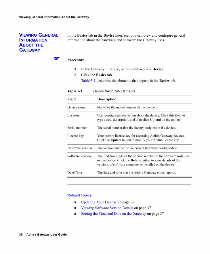
VIEWING GENERAL INFORMATION ABOUT THE GATEWAY
In the Basics tab in the Device interface, you can view and configure general information about the hardware and software the Gateway uses.
Procedure
1 In the Gateway interface, on the sidebar, click Device.2 Click the Basics tab.
Table 3-1 describes the elements that appear in the Basics tab.
Related Topics
Updating Your License on page 37 Viewing Software Version Details on page 37 Setting the Time and Date on the Gateway on page 37
Table 3-1 Device Basic Tab Elements
Field Description
Device name Identifies the model number of the device.
Location User-configured description about the device. Click this field to type a new description, and then click Upload on the toolbar.
Serial number The serial number that the factory assigned to the device.
License key Your Aethra license key for accessing Aethra Gateway devices. Click the Update button to modify your Aethra license key.
Hardware version The version number of the current hardware configuration.
Software version The first two digits of the version number of the software installed on the device. Click the Details button to view details of the versions of software components installed on the device.
Date/Time The date and time that the Aethra Gateway clock reports.
Configuring the Aethra Gateway 37
Viewing General Information About the Gateway
Setting the Gateway Location on page 38 Resetting Default Device Basic Settings on page 39
UPDATING YOUR LICENSE
You use the Basics tab to update your Gateway license.
Procedure
1 On the sidebar, click Device.2 Click the Basics tab.
The Licensing and Registration dialog box appears.3 Access the Aethra web site to register before requesting a new
license key by clicking the Click here to register at the web site link, or by copying the URL that appears in the lower half of the screen into your browser.
4 Type your new license key in the New license key field and click Upload to activate the new license key.
VIEWING SOFTWARE VERSION DETAILS
You use the Basics tab to view expanded software version information.
Procedure
1 On the sidebar, click Device.2 Click the Basics tab.3 Locate the Software version field and click Details.
The Version Details dialog box appears.
SETTING THE TIME AND DATE ON THE GATEWAY
You use the Basics tab to choose how your Gateway tracks the date and time.
Procedure
1 On the sidebar, click Device.2 Click the Basics tab.
38 Aethra Gateway User Guide
Viewing General Information About the Gateway
3 Locate the Date/Time field and click Change.The Change Time dialog box appears. The date and time the Gateway reports appear in the Set time to field.
4 In the Change field, select the unit of time that you want to change.
Note There is no unit to change AM and PM. This designation rolls automatically when the hour rolls past 12 backward or forward. Similarly, seconds roll minutes, minutes roll hours, hours roll days, and days roll months.
5 In the Set time to field, choose the up or down arrow to change that unit.The unit you choose changes in the direction you choose: higher (up) or lower (down).
6 Repeat step 4 and 5 for as many units as you want to change.7 On the toolbar, click Upload.
SETTING THE GATEWAY LOCATION
You can install the Gateway anywhere on your network including at a remote site. In the Basics tab, you can describe the current location of the Gateway.
Procedure
1 On the sidebar, click Device.2 Click the Basics tab.3 In the Location field, enter the location information about the
Gateway that you want to display.The field displays up to 23 characters.
4 On the toolbar, click Upload to save to configuration memory.
Configuring the Aethra Gateway 39
Viewing Address Settings
RESETTING DEFAULT DEVICE BASIC SETTINGS
In the Basics tab, you can restore board basic settings to factory defaults.
Procedure
1 On the sidebar, click Device.2 Click the Basics tab.3 Select the Reset to default settings check box.
VIEWING ADDRESS SETTINGS
In the Addressing tab, you can view address information for the Gateway such as IP address informations, Domain Name Server (DNS) information and Ethernet port speed and duplex. Table 3-2 describes the elements that appear on the Addressing tab.
Table 3-2 Addressing Tab Elements
Field Description
IP Address
IP Address The IP address assigned to the Gateway.
Router IP The address of the router that the Gateway uses.
Subnet Mask The subnet address that the Gateway uses.
DNS
DNS Server IP The IP address of the Domain Name Server (DNS) that the Gateway accesses.
Device DNS name The device name of the Domain Name Server (DNS) that the Gateway accesses (read-only).
Ethernet
Port type Displays information about the Ethernet connection (read-only).
Port settings The Ethernet speed and duplex that the Gateway uses.
40 Aethra Gateway User Guide
Viewing Address Settings
Related Topics
Changing Address Settings on page 40
CHANGING ADDRESS SETTINGS
In the Addressing tab, you can change the following address information for the Gateway—IP address information, DNS information and the Ethernet port speed and duplex.
Procedure
1 In the Administrator interface, on the sidebar, click Device.2 Click the Addressing tab.3 To change an IP address setting, do any of the following steps:
In the IP Address field, type the IP address you want to assign to the Gateway.
In the Router IP field, type the IP address of the router you want the Gateway to use.
In the Subnet Mask field, type the subnet mask you want the Gateway to use.
4 In the DNS Server IP field, type the IP address of the DNS server that you want the Gateway to use.
5 In the Port settings field, choose the Ethernet port and duplex speed value you want to set.
6 On the toolbar, click Upload.
MAC address Displays the Mandatory Access Control (MAC) code assigned to the Gateway (read-only).
Port status Displays the actual Ethernet speed and duplex the Gateway uses on the network (read-only).
Table 3-2 Addressing Tab Elements (continued)
Field Description
Configuring the Aethra Gateway 41
Changing the Administrator Interface Web Server Port
Related Topics
Viewing Address Settings on page 39
CHANGING THE ADMINISTRATOR INTERFACE WEB SERVER PORT
Port 80 is the default Administrator interface web server port. For additional security, you can modify the web server port in the Web tab.
Procedure
1 In the Gateway interface, on the sidebar, click Device. 2 Click the Web tab.3 In the Web server port field, enter the port number.4 On the toolbar, click Upload.
CONFIGURING SECURITY
You can configure the access that external programs have to the Gateway. These external programs include Telnet, Simple Network Management Protocol (SNMP), File Transfer Protocol (FTP), and ICMP (Internet Control Message Protocol, or ping).
Procedure
1 In the Gateway interface, on the sidebar, click Device.2 Click the Security tab.3 From the Security mode field, choose the access level you
want the Gateway to support: Standard—Enables SNMP, Telnet, FTP, and ICMP to
access the Gateway. High (no Telnet or Ftp)—Enables access to the
Gateway only through SNMP and ICMP. Maximum (no Telnet, ftp, SNMP, or ICMP)—
Disallows external programs to access the Gateway.
42 Aethra Gateway User Guide
About the Gateway Administrator Interface
4 In the SNMP Read community and Write community fields, enter default strings used to enable SNMP communication between the Gateway and a external application.
5 On the toolbar, click Upload.
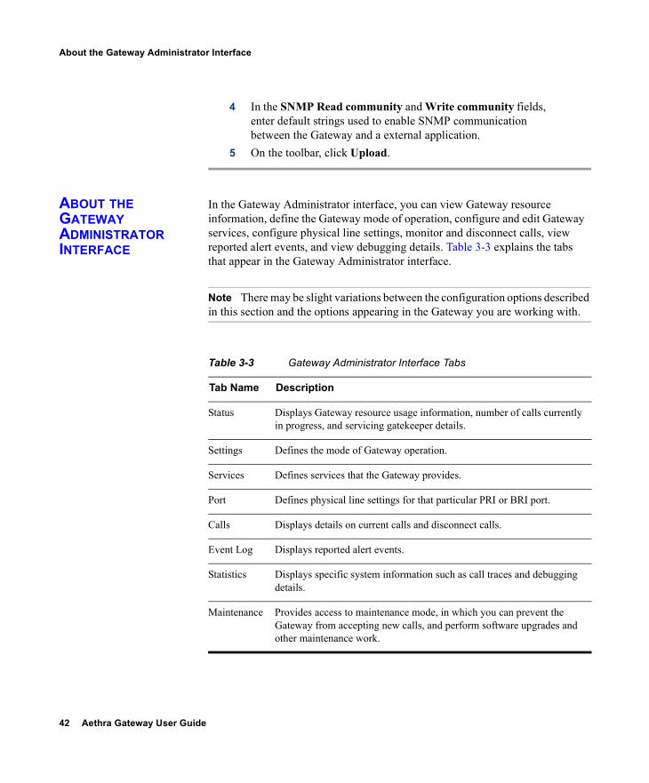
ABOUT THE GATEWAY ADMINISTRATOR INTERFACE
In the Gateway Administrator interface, you can view Gateway resource information, define the Gateway mode of operation, configure and edit Gateway services, configure physical line settings, monitor and disconnect calls, view reported alert events, and view debugging details. Table 3-3 explains the tabs that appear in the Gateway Administrator interface.
Note There may be slight variations between the configuration options described in this section and the options appearing in the Gateway you are working with.
Table 3-3 Gateway Administrator Interface Tabs
Tab Name Description
Status Displays Gateway resource usage information, number of calls currently in progress, and servicing gatekeeper details.
Settings Defines the mode of Gateway operation.
Services Defines services that the Gateway provides.
Port Defines physical line settings for that particular PRI or BRI port.
Calls Displays details on current calls and disconnect calls.
Event Log Displays reported alert events.
Statistics Displays specific system information such as call traces and debugging details.
Maintenance Provides access to maintenance mode, in which you can prevent the Gateway from accepting new calls, and perform software upgrades and other maintenance work.
Configuring the Aethra Gateway 43
About the Gateway Administrator Interface
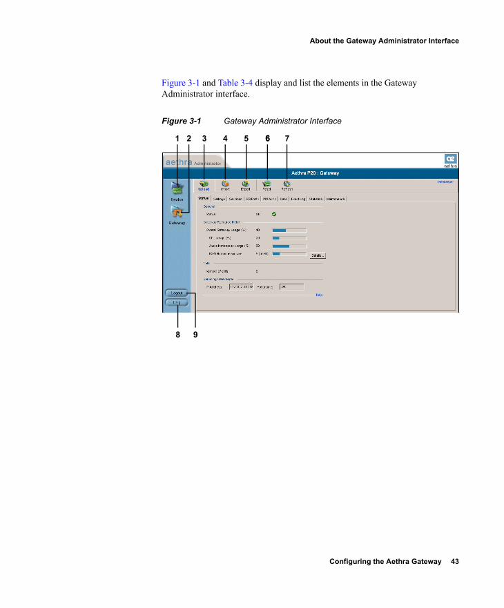
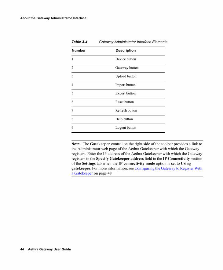
Figure 3-1 and Table 3-4 display and list the elements in the Gateway Administrator interface.
Figure 3-1 Gateway Administrator Interface
8 9
1 2 3 4 5 6 76
44 Aethra Gateway User Guide
About the Gateway Administrator Interface
Note The Gatekeeper control on the right side of the toolbar provides a link to the Administrator web page of the Aethra Gatekeeper with which the Gateway registers. Enter the IP address of the Aethra Gatekeeper with which the Gateway registers in the Specify Gatekeeper address field in the IP Connectivity section of the Settings tab when the IP connectivity mode option is set to Using gatekeeper. For more information, see Configuring the Gateway to Register With a Gatekeeper on page 48
Table 3-4 Gateway Administrator Interface Elements
Number Description
1 Device button
2 Gateway button
3 Upload button
4 Import button
5 Export button
6 Reset button
7 Refresh button
8 Help button
9 Logout button

Configuring the Aethra Gateway 45
Viewing the Status Tab
VIEWING THE STATUS TAB
The Status tab displays the current rate of use of Gateway resources, the total number of current calls, and servicing details. Table 3-5 lists the information in the Status tab.
Related Topics
Viewing B Channel Status Refreshing Gateway Status
Table 3-5 Status Tab Sections
Section Name Description
General Status—Indicates the operational status of the Gateway: OK or Failure. In cases of failure, a text description of the problem appears. For example, “PRI connection, remote side: loss of frame alignment.”
Gateway Resource Meter
Overall Gateway usage (%)—Displays the rate of Gateway resources currently in use.
CPU usage (%)—Displays the rate of CPU resources currently in use.
Audio transcoder usage (%)—Displays the rate of audio transcoding resources currently used for video calls.
ISDN B channels in use—Displays the total number of Integrated Services Digital Network (ISDN) B channels currently in use.
Calls Number of calls—Displays the total number of calls currently in progress in the Gateway.
Servicing Gatekeeper
IP address—Displays the IP address of the gatekeeper to which the Gateway is currently registered.
Host name—Displays the name of the servicing gatekeeper.
46 Aethra Gateway User Guide
Viewing the Status Tab
VIEWING B CHANNEL STATUS
Note This section applies only to Aethra P20.
From the Status tab in the Gateway interface, you can view detailed status information for each B channel.
Procedure
1 In the Gateway interface, on the sidebar, click Gateway (if not already selected).
2 Click the Status tab (if not already selected).3 Click Details.
The Details dialog box appears, displaying the following information: Port 1 and Port 2—Displays the status of each of the
B channels and of the D channel for each of the PRI ports.
Disabled—Displays the number of disabled B channels for each port.
Used—Displays the number of B channels currently in use for each port.
Free—Displays the number of B channels currently available for each port.
D channel—Displays the number of D channels for each port.
REFRESHING GATEWAY STATUS
You can refresh the information that appears in the Status tab.
Procedure
1 In the Gateway interface, on the sidebar, click Gateway (if not already selected).
2 Click the Status tab (if not already selected).3 On the toolbar, click Refresh.
The information that appears in the Status tab is now refreshed.
Configuring the Aethra Gateway 47
Configuring Gateway Settings
CONFIGURING GATEWAY SETTINGS
In the Settings tab of the Gateway interface, you can configure gatekeeper and Interactive Voice Response (IVR) addressing, the type of connection to the IP network, dialing delimiters, media encoding/decoding protocols, Quality of Service levels, which events cause the Gateway to send SNMP traps, Gateway resource levels for T.120 enabled and audio transcoded video calls, security settings, and advanced settings such as load balancing support.The following topics discuss the settings you can configure in the Settings tab:
Configuring Basic Gateway Settings on page 47 Configuring IP Connectivity Settings on page 48 Configuring IVR Settings on page 55 Configuring Outgoing Call Delimiters on page 56 About Encoding/Decoding Protocols on page 57 Configuring Encoding/Decoding Protocols on page 59 Configuring ISDN Channel Bonding Settings for Downspeeding on
page 60 Configuring Quality of Service Settings on page 62 Configuring Alert Indications on page 64 Configuring Gateway Resources for Calls on page 70 Configuring Gateway Encryption on page 72 Configuring Advanced Settings on page 73 About DTMF Settings on page 79 Configuring Advanced Commands on page 83
CONFIGURING BASIC GATEWAY SETTINGS
In the Basics section of the Settings tab, you can set the Gateway identifier, which is the name that the Gateway uses when registering to a gatekeeper and when dialing to endpoints.
Procedure
1 In the Gateway interface, on the sidebar, click Gateway (if not already selected).
2 Click the Settings tab.3 Click the Basics button (if not already selected).4 In the Gateway Identifier field, type the Gateway identifier.
48 Aethra Gateway User Guide
Configuring Gateway Settings
CONFIGURING IP CONNECTIVITY SETTINGS
In the IP Connectivity section of the Settings tab, you can select the IP connectivity mode in which the Gateway operates, set the address of the gatekeeper with which the Gateway registers, and define the way in which the Gateway interacts with the gatekeeper.You can configure the IP connectivity mode in the following two ways:
Using a gatekeeper—The Gateway registers with a gatekeeper and uses the gatekeeper for every call (see Configuring the Gateway to Register With a Gatekeeper on page 48).
Peer-to-Peer—The Gateway connects directly to a peer device without the need for a gatekeeper (see Configuring the Gateway for Peer-to-Peer IP Connectivity on page 50).
Caution Changing the IP connectivity mode setting causes the Gateway to reset.
CONFIGURING THE GATEWAY TO REGISTER WITH A GATEKEEPER
In the IP Connectivity section of the Settings tab, you can configure the Gateway to register with a gatekeeper.
Procedure
1 In the Gateway interface, on the sidebar, click Gateway (if not already selected).
2 Click the Settings tab.3 Click the IP Connectivity button.4 In the IP connectivity mode field, choose Using gatekeeper.5 Make one of the following selections:
Select the Gatekeeper auto discover and register option button for the Gateway to automatically search for and attempt to register to a gatekeeper.
Select the Specify Gatekeeper address option button to specify the gatekeeper to which the Gateway registers.
6 In the Gatekeeper address field, do one of the following: Type the IP address of the gatekeeper to which the
Gateway registers.—or—
Configuring the Aethra Gateway 49
Configuring Gateway Settings
Click Browse.The Discovered Gatekeepers dialog box appears, displaying all gatekeepers located on the same network segment as the Gateway.
Select a discovered gatekeeper. Click OK.
7 In the Gatekeeper port field, type the port number of the gatekeeper. The default setting is 1719.
8 Select the Registration refresh every n seconds check box to set the Time To Live interval (in seconds) that determines how often the Gateway sends a “keep alive” message to the gatekeeper to ensure that the Gateway registration is listed with the gatekeeper and does not expire. Enter a value in seconds in the field.
9 In the Gateway registration mode field, choose the method of registration of services with the gatekeeper: Version 1—For gatekeepers that support H.323
version 1. Version 2—For gatekeepers that support H.323
version 2 or later.10 (PRI gateways only) Select the Unregister from Gatekeeper
on ISDN connection failure check box to force the Gateway to unregister from its gatekeeper when both ISDN D-channel connections are no longer active. The gatekeeper is forced to send new IP-to-ISDN calls through a different Gateway, thus ensuring high call completion rates. The Gateway re-registers to the gatekeeper when the ISDN connected is restored.
11 Select the Send load balancing messages (RAI) check box to enable the sending of RAI messages to the gatekeeper for the purpose of load balancing on the network. If you select this option, perform step 12 and step 13.Gatekeepers can perform load balancing on the network using feedback from the Gateway in the form of Resource Available Indication (RAI) messages that inform the gatekeeper of
50 Aethra Gateway User Guide
Configuring Gateway Settings
Gateway resource availability. If the Gateway is unavailable, the gatekeeper performs line hunting operations to route the call to an alternative gateway.When you set the Gateway for RAI/RAC, it sends periodic RAI messages that inform the gatekeeper of the current resource availability in the Gateway. The gatekeeper responds with Resource Available Confirmation (RAC) messages to acknowledge receipt of the RAI messages. In step 12 and step 13, you can configure the upper and lower threshold for triggering RAI messages according to resource availability in the Gateway.
12 In the Send ‘busy’ when load is more than field, enter the upper threshold for Gateway resource utilization as a percentage of total resources. When resource use is greater than the threshold, the Gateway sends the gatekeeper a ‘busy’ RAI message, indicating to the gatekeeper that it should stop routing calls to this Gateway.
13 In the Send ‘free’ when load is more than field, enter the lower threshold for Gateway resource utilization as a percentage of total resources. When resource use is less than the threshold, the Gateway sends the gatekeeper a ‘free’ RAI message, indicating to the gatekeeper that it can resume routing calls to this Gateway.
CONFIGURING THE GATEWAY FOR PEER-TO-PEER IP CONNECTIVITY
In the IP Connectivity section of the Settings tab, you can configure the Gateway for peer-to-peer IP connectivity.
Procedure
1 In the Gateway interface, on the sidebar, click Gateway (if not already selected).
2 Click the Settings tab.3 Click the IP Connectivity button.
Configuring the Aethra Gateway 51
Configuring Gateway Settings
4 In the IP connectivity mode field, choose Peer-to-Peer.
Note Changing this setting causes the Gateway to reset.
5 In the Peer hunting mode field, choose one of the following options: Always start from first peer—The Gateway attempts
to connect a call to the first peer device on the Peer list section. If the call fails due to one of the H.323 call disconnect reasons (see About Peer-to-Peer H.323 Call Disconnect Reasons on page 54), the Gateway tries each peer device in the Peer list section in order until the call is successfully connected. If the Gateway fails to connect the call after trying all the peer devices on the list, it rejects the call.
Always start from last successful peer—The Gateway attempts to connect a call to the last peer device in the Peer list section with which a call was successfully established. An arrow in the Peer list section indicates with which of the peer devices a call was last connected successfully. If the call fails due to one of the H.323 call disconnect reasons (see About Peer-to-Peer H.323 Call Disconnect Reasons on page 54), the Gateway tries each peer device in the Peer list section in order until the call is successfully connected. The arrow moves to the peer device with which the call connection is successful. If the Gateway fails to connect the call after trying all the peer devices on the list, it rejects the call and the arrow indicates with which peer device a call was last connected successfully. This is the default setting.
52 Aethra Gateway User Guide
Configuring Gateway Settings
Round Robin—As for the Always start from last successful peer setting, except that the arrow advances to the next peer device in the Peer list section even if the call connection succeeds.
Note The peer hunting process starts when any of the following events occur: the Gateway fails to establish a Transmission Control Protocol (TCP) connection to the specified peer device after a timeout; the Gateway receives a “Release Complete” message from a peer device with a “No Resources” call rejection reason, or one of the other reasons that the Peer-to-Peer disconnect reason add advanced command specifies; or the Gateway establishes a TCP connection to the specified peer device, but does not receive a valid H.323 message from the peer device after a timeout.
6 In the Peer list section, you can configure peer devices currently configured to work with the Gateway. The Peer list section displays all configured peer devices in a table with the following columns: Peer #—The sequential number of the peer in the list. Description—The description of the peer device. IP Address—The peer IP address. IP Port—The peer IP port number. Calls—Displays “Yes” or “No” to indicate whether or
not there are currently any active calls between the peer and Gateway.
To change the order of peer devices used in peer hunting, select a peer device and click the up or down arrow button to change its order.To add or edit a peer device, click Add or select the peer device and click Edit. Perform the following steps in the Add peer or Edit peer dialog box: In the IP Address field, type or edit the peer IP
address.
Note Two peers cannot have the same IP address or host name/Uniform Resource Locator (URL).
Configuring the Aethra Gateway 53
Configuring Gateway Settings
In the IP Port field, enter or edit the peer IP port number.
In the Description field, enter or edit the description of the peer.
Click Upload.
Note You cannot add a single peer to the Peer list section more than once.
To delete a peer device, select the peer device and click Delete. Deleting a peer does not cause its active calls to disconnect, but no new calls are routed to the deleted peer.
Note The peer hunting process stops when one of the peer devices accepts the call or when the call is rejected with a disconnect reason. When a Gateway has scanned the Peer list section and still cannot connect a call, the following rules apply: if at least one of the peers rejected the call due to capacity overload, the call rejection reason (towards the call originator) is “No Resources”; in all other cases, the call rejection reason is “Unreachable Destination.”
7 In the Peer hunting timeout (sec) field, enter the length of time (between 1 and 10 seconds) for which the Gateway waits for a Transmission Control Protocol (TCP) response from each peer device contacted. The default value is 5 seconds.
8 Select the Accept calls from defined peers only check box if you want the Gateway to reject incoming calls from IP-side entities not defined in the peer list. If deselected, the Gateway allows incoming calls from IP-side entities not defined in the Peer list section.
9 In the Reject calls from peer devices when less than n B channels are free field, type the lower capacity threshold for rejecting calls from H.323 peer devices. The default setting is 6.
54 Aethra Gateway User Guide
Configuring Gateway Settings
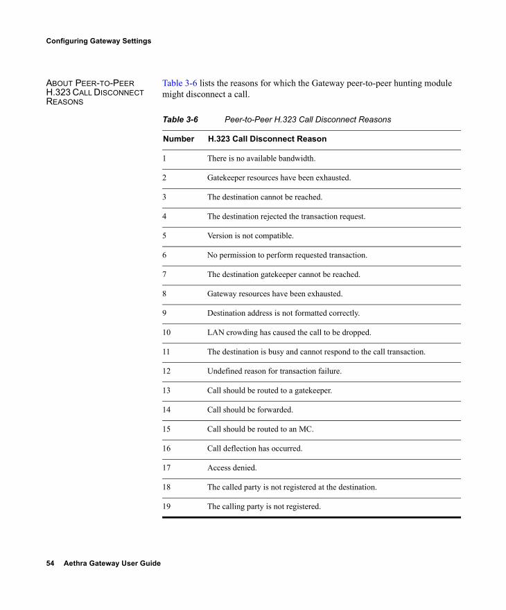
ABOUT PEER-TO-PEER H.323 CALL DISCONNECT REASONS
Table 3-6 lists the reasons for which the Gateway peer-to-peer hunting module might disconnect a call.
Table 3-6 Peer-to-Peer H.323 Call Disconnect Reasons
Number H.323 Call Disconnect Reason
1 There is no available bandwidth.
2 Gatekeeper resources have been exhausted.
3 The destination cannot be reached.
4 The destination rejected the transaction request.
5 Version is not compatible.
6 No permission to perform requested transaction.
7 The destination gatekeeper cannot be reached.
8 Gateway resources have been exhausted.
9 Destination address is not formatted correctly.
10 LAN crowding has caused the call to be dropped.
11 The destination is busy and cannot respond to the call transaction.
12 Undefined reason for transaction failure.
13 Call should be routed to a gatekeeper.
14 Call should be forwarded.
15 Call should be routed to an MC.
16 Call deflection has occurred.
17 Access denied.
18 The called party is not registered at the destination.
19 The calling party is not registered.
Configuring the Aethra Gateway 55
Configuring Gateway Settings
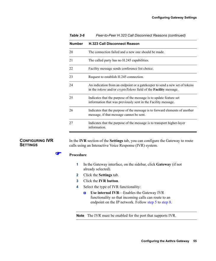
CONFIGURING IVR SETTINGS
In the IVR section of the Settings tab, you can configure the Gateway to route calls using an Interactive Voice Response (IVR) system.
Procedure
1 In the Gateway interface, on the sidebar, click Gateway (if not already selected).
2 Click the Settings tab.3 Click the IVR button.4 Select the type of IVR functionality:
Use internal IVR—Enables the Gateway IVR functionality so that incoming calls can route to an endpoint on the IP network. Follow step 5 to step 8.
Note The IVR must be enabled for the port that supports IVR.
20 The connection failed and a new one should be made.
21 The called party has no H.245 capabilities.
22 Facility message sends conference list choice.
23 Request to establish H.245 connection.
24 An indication from an endpoint or a gatekeeper to send a new set of tokens in the tokens and/or cryptoTokens field of the Facility message.
25 Indicates that the purpose of the message is to update feature set information that was previously sent in the Facility message.
26 Indicates that the purpose of the message is to forward elements of another message, if that message cannot be sent.
27 Indicates that the purpose of the message is to transport higher-layer information.
Table 3-6 Peer-to-Peer H.323 Call Disconnect Reasons (continued)
Number H.323 Call Disconnect Reason
56 Aethra Gateway User Guide
Configuring Gateway Settings
Use external IVR—Select to set the IP address and port number for an IVR system in another device. Follow step 9 and step 10.
5 In the IVR registration name field, type the IVR registration alias used with the gatekeeper.
6 Deselect the Transfer to Operator when ‘*’ pressed during IVR check box to ignore the IVR operator digit (which is currently “*”) and make it part of the dial string.
7 In the IVR Operator Extension field, set the E.164 number of an endpoint that is registered with the gatekeeper to function as an IVR operator for incoming calls. To do this, type the same number for the IVR operator extension for each of the IP terminals that you want to include in the single number access. You can also use an ISDN endpoint as the IVR operator extension. To do this, define the IVR operator extension using the format <Gateway service><ISDN number>.
8 Select the IVR registers with gatekeeper check box to enable the internal IVR to register with the gatekeeper.
9 In the IVR address field, type the IP address for the IVR system on the external device.
10 In the Port field, type the port number for the IVR system on the external device. The default port setting is 1620.
CONFIGURING OUTGOING CALL DELIMITERS
In the Delimiters section of the Settings tab, you can configure outgoing call delimiter characters.
Procedure
1 In the Gateway interface, on the sidebar, click Gateway (if not already selected).
2 Click the Settings tab.3 Click the Delimiters button.4 In the Second number delimiter field, type the character used
as a second number delimiter for dialing more than one ISDN number in setting up a 2B call. You can use the pound sign (#), asterisk (*) or comma (,) as a delimiter in outgoing calls only.
Configuring the Aethra Gateway 57
Configuring Gateway Settings
5 In the TCS4 extension delimiter field, type the character used as an extension number for TCS4 outgoing IP-to-ISDN call routing. You can use the pound sign (#), asterisk (*) or comma (,) as a delimiter in outgoing calls only. This setting does not apply for voice calls.
Note Since the comma cannot be used in the Party number field of the MCU Conference Control interface, we recommend that you do not use the comma as a second number delimiter or as a TCS4 extension delimiter.
ABOUT ENCODING/DECODING PROTOCOLS
A number of video conferencing terminal applications require the G.722 and G.722.1 audio compression codecs to provide high quality voice communications. The G.722 and G.722.1 formats, using a digital sampling rate of 7 KHz, provide higher quality voice sampling with a greater dynamic range. The Gateway does not transcode G.722 or G.722.1, but supports them transparently. Since the G.722 codec is of a much higher audio quality than other codecs and requires higher bandwidths, the Gateway supports G.722 and G.722.1 at the following call bit rates:
G.722 is supported in calls at 224, 256, 336, 384, 448, 512 Kbps (all Gateways) and 768, 1472 and 1920 Kbps (PRI gateways only).
G.722.1 is supported in calls at 64, 2B, and 128 Kbps.
Both endpoints in a call must support G.722 and G.722.1 audio codecs.
ABOUT AUDIO TRANSCODING
The Aethra P20 supports audio transcoding through the Audio Transcoder Module (TCM). Other Aethra Gateways support audio transcoding through on-board Digital Signal Processing (DSP).The TCM is a PCI mezzanine card (PMC) that implements Digital Signal Processing (DSP). The TCM has a processing capacity of up to 20 channels for audio transcoding in video calls.The Gateway TCM can perform audio transcoding between the following types of audio protocols:
G.711 (ISDN) to G.723.1 (IP) G.723.1 (IP) to G.711 (ISDN)
58 Aethra Gateway User Guide
Configuring Gateway Settings
G.728 (ISDN) to G.711 (IP) G.711 (IP) to G.728 (ISDN)
Note When your unit includes both a Gateway and MCU, G.728 transcoding is supported on the MCU only.
Each audio codec differs in the audio quality, compression, and bit rates that it provides. The G.711 codec provides toll quality audio at 64 Kbps, the G.728 codec provides near toll quality audio at 16 Kbps, and the G.723.1 codec provides voice quality audio at 5.3 or 6.4 Kbps. Endpoints on the ISDN network usually support the G.711 and G.728 codecs. Endpoints on IP networks support G.711 and G.723.1 codecs. By performing transcoding between these audio protocols, the Gateway can support communication between endpoints with codecs that are incompatible with each other. Audio transcoding can also optimize the audio bandwidth usage either on the IP network (G.723.1 < > G.711) or on the ISDN network (G.728 < > G.711). Transcoding is particularly useful for ISDN codecs, where bandwidth can be limited to 128 Kbps for a video call. For example, when transcoding between G.728 and G.711 takes place, the audio bandwidth usage is compressed to 16 Kbps. This provides an additional 40 Kbps of bandwidth to the existing video bit rate on the ISDN network, contributing to improved video quality.
Note The Gateway automatically performs A-Law G.711-to-µ-Law G.711 translation between the IP and ISDN sides if needed.
You can configure the Gateway to prioritize the transcoding, giving preference to a particular codec that is applied to calls, thus optimizing the resource allocation utilized by each call.
ABOUT T.120 DATA COLLABORATION SUPPORT
The Gateway provides full end-to-end support for T.120 data collaboration sessions, provided all terminals support the T.120 standard in their conferencing applications. In video calls with data transfer, the Gateway accepts whatever bandwidth the ISDN connection defines for the data and dynamically adjusts the outgoing bandwidth used for data by using the MLP, HMLP and VarMLP formats.
Configuring the Aethra Gateway 59
Configuring Gateway Settings
If transcoding or T.120 capabilities are required, the Gateway has to reserve resources for these. The Gateway can differentiate between those calls that support T.120 and those that do not. When receiving calls, the Gateway can check whether you are reserving resources for transcoding or for T.120 capabilities. The Gateway enables the user to determine the trade-off between the number of non-T.120 calls that the Gateway can support and the number of calls sent with T.120 capabilities. The total number of calls that the Gateway can support is accordingly reduced by this reallocation of resources.The H.320 standard defines space allocation within a call. The H.320 standard defines the logic for bit rate allocation among audio, video and data channels in the context of the overall bit rate of a call. If you work with T.120, reallocation of bandwidth is always at the expense of available video resources. The requirements of the H.320 standard govern this reallocation—it is not configured in the Gateway. The Gateway simply decides whether or not to send T.120 capabilities. You configure T.120 capabilities in the Advanced section of the Gateway interface Settings tab.
CONFIGURING ENCODING/DECODING PROTOCOLS
In the Media Modes section of the Settings tab, you can configure and prioritize encoding and decoding protocols.
Procedure
1 In the Gateway interface, on the sidebar, click Gateway (if not already selected).
2 Click the Settings tab.3 Click the Media Modes button.4 In the Transcoding priority field, choose the priority that
determines the order of requested audio transcoding or choose Disable to disable audio transcoding priority.
Note When your unit includes both a Gateway and an MCU, G.728 transcoding is supported on the MCU only.
5 You can configure the following audio codec settings: Select the Enable G.722 check box to enable
transparent support for the G.722 audio codec.
60 Aethra Gateway User Guide
Configuring Gateway Settings
Select the Enable G.722.1 check box to enable transparent support for the G.722.1 audio codec.
Select the Enable G.728 check box to enable transparent support for the G.728 audio codec.
6 You can configure the following video codec settings: Select the Enable H.263 check box to enable
transparent support for the H.263 video codec. Select the Enable H.263+ check box to enable
transparent support for the H.263+ video codec. Select the Enable H.264 check box to enable
transparent support for the H.264 video codec.7 You can configure the following data settings:
Select the Enable T.120 check box to enable transparent support for T.120 capabilities.
Select the Enable FECC check box to enable transparent support for Far End Camera Control (FECC) capabilities.
CONFIGURING ISDN CHANNEL BONDING SETTINGS FOR DOWNSPEEDING
In the Bonding section of the Settings tab, you can configure ISDN channel bonding parameters that affect downspeeding functionality. Downspeeding is the ability to complete and maintain a call when ISDN conditions are bad. In downspeeding, call capabilities are automatically renegotiated when a call fails. Downspeeding contributes to a higher percentage of call completion on the network. The Gateway supports downspeeding at call setup and in mid-call.With downspeeding, when connection problems occur at call setup, the Gateway attempts to connect a call at a lower bit rate than that requested. Administrators can configure the Gateway to attempt to connect a video call at a specified minimum bit rate, or to attempt to connect the call as a voice call.In downspeeding, when connection problems occur in mid-call, the Gateway attempts to connect a video call at the specified lower bit rate. When downspeeding is complete and the call is connected at the specified lower bit rate, the Gateway notifies the Internet Protocol (IP) endpoint of the new call rate.
Configuring the Aethra Gateway 61
Configuring Gateway Settings
Procedure
1 In the Gateway interface, on the sidebar, click Gateway (if not already selected).
2 Click the Settings tab.3 Click the Bonding button.4 Select the Enable bonding check box to enable ISDN bonding
support.5 In the Maximum B channels for bonded call field, choose the
maximum number of B channels—3, 4, 5, 6, 8, 12, 23 or 30—that you want to allow for a single bonded call. The default setting for PRI gateways is 30. The default setting for BRI Gateways is 8. When the number of B channels required to process a bonded call exceeds the number specified in this field, the Gateway performs downspeeding as shown in Table 3-7.
6 In the For bonded calls, allow downspeeding down to n B channels field, choose the minimum number of B channels that must be available before the Gateway attempts to reconnect a video call.
Table 3-7 Downspeeding Policy Operation
Call Direction Downspeed Advanced Command Parameter
If Call B Channels Exceed the Maximum:
IP (LAN) to WAN (ISDN) enable (default)
Gateway tries to call at the maximum number of B channels
IP (LAN) to WAN (ISDN) disable Call disconnects
WAN (ISDN) to LAN (IP) enable (default)
Call disconnects
WAN (ISDN) to LAN (IP) disabled Call disconnects.
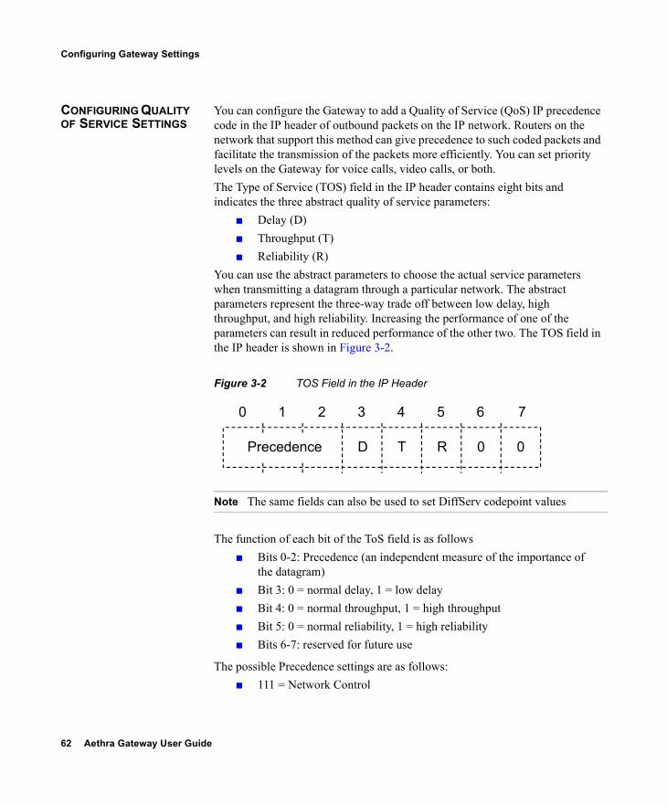
62 Aethra Gateway User Guide
Configuring Gateway Settings
CONFIGURING QUALITY OF SERVICE SETTINGS
You can configure the Gateway to add a Quality of Service (QoS) IP precedence code in the IP header of outbound packets on the IP network. Routers on the network that support this method can give precedence to such coded packets and facilitate the transmission of the packets more efficiently. You can set priority levels on the Gateway for voice calls, video calls, or both.The Type of Service (TOS) field in the IP header contains eight bits and indicates the three abstract quality of service parameters:
Delay (D) Throughput (T) Reliability (R)
You can use the abstract parameters to choose the actual service parameters when transmitting a datagram through a particular network. The abstract parameters represent the three-way trade off between low delay, high throughput, and high reliability. Increasing the performance of one of the parameters can result in reduced performance of the other two. The TOS field in the IP header is shown in Figure 3-2.
Figure 3-2 TOS Field in the IP Header
Note The same fields can also be used to set DiffServ codepoint values
The function of each bit of the ToS field is as follows Bits 0-2: Precedence (an independent measure of the importance of
the datagram) Bit 3: 0 = normal delay, 1 = low delay Bit 4: 0 = normal throughput, 1 = high throughput Bit 5: 0 = normal reliability, 1 = high reliability Bits 6-7: reserved for future use
The possible Precedence settings are as follows: 111 = Network Control
Precedence D T R 0 0
0 1 2 3 4 5 6 7

Configuring the Aethra Gateway 63
Configuring Gateway Settings
110 = Internetwork Control 101 = CRITIC/ECP 100 = Flash Override 011 = Flash 010 = Immediate 001 = Priority 000 = Routine
In the Quality of Service section of the Settings tab, you can assign a priority level to video and voice calls.
Procedure
1 In the Gateway interface, on the sidebar, click Gateway (if not already selected).
2 Click the Settings tab.3 Click the Quality of Service button.4 In the Quality of service support field, select one of the
following option buttons: None—Select to disable quality of service support. Default (recommended)—Select to assign the default
IP Type of Service (ToS) value for each media type. Custom—Select to assign your own IP ToS value for
each media type. You can configure the following additional settings: In the Control Priority (0-63) field, enter a
whole number from 0 to 63 to set the priority level of signaling packets that the Gateway sends out. The default value is 26.
In the Video Calls section Voice Priority (0-63) field, enter a whole number from 0 to 63 to set the priority level of voice packets that the Gateway sends out. The default value is 46.
In the Video Priority (0-63) field, enter a whole number from 0 to 63 to set the priority level of video packets that the Gateway sends out. The default value is 34.
64 Aethra Gateway User Guide
Configuring Gateway Settings
In the Data Priority (0-63) field, enter a whole number from 0 to 63 to set the priority level of data packets that the Gateway sends out. The default value is 26.
In the Voice Calls section Voice Priority (0-63) field, enter a whole number from 0 to 63 to set the priority level of voice packets that the Gateway sends out. The default value is 46.
Note You can click Restore Defaults to restore all default settings.
CONFIGURING ALERT INDICATIONS
In the Alert Indications section of the Settings tab, you can select which events trigger Simple Network Management Protocol (SNMP) traps. You can also define multiple SNMP servers to which the Gateway sends the SNMP traps.
Note The Gateway supports traps in the SNMPv1 format.
Procedure
1 In the Gateway interface, on the sidebar, click Gateway (if not already selected).
2 Click the Settings tab.3 Click the Alert Indications button.4 In the Events section, select events in the Disabled events
field and click Add to select an event to monitor. Or, select an event in the Enabled events field and click Remove to remove that event from monitoring.
5 Select the Send SNMP Traps check box to configure the IP address of the SNMP server to which the Gateway sends SNMP trap notifications of the events selected in the Enabled events field. You can configure up to three different SNMP trap servers.
6 In the Trap server IP and Port fields, enter the IP address and port number for each SNMP server to which you want the Gateway to send SNMP trap notifications. To remove an
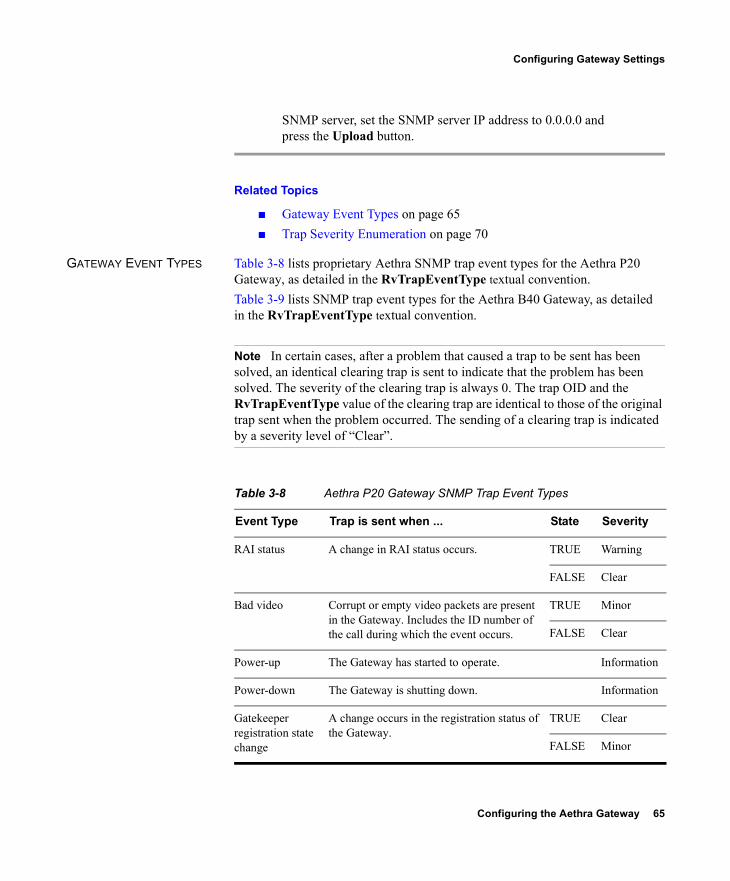
Configuring the Aethra Gateway 65
Configuring Gateway Settings
SNMP server, set the SNMP server IP address to 0.0.0.0 and press the Upload button.
Related Topics
Gateway Event Types on page 65 Trap Severity Enumeration on page 70
GATEWAY EVENT TYPES Table 3-8 lists proprietary Aethra SNMP trap event types for the Aethra P20 Gateway, as detailed in the RvTrapEventType textual convention.Table 3-9 lists SNMP trap event types for the Aethra B40 Gateway, as detailed in the RvTrapEventType textual convention.
Note In certain cases, after a problem that caused a trap to be sent has been solved, an identical clearing trap is sent to indicate that the problem has been solved. The severity of the clearing trap is always 0. The trap OID and the RvTrapEventType value of the clearing trap are identical to those of the original trap sent when the problem occurred. The sending of a clearing trap is indicated by a severity level of “Clear”.
Table 3-8 Aethra P20 Gateway SNMP Trap Event Types
Event Type Trap is sent when ... State Severity
RAI status A change in RAI status occurs. TRUE Warning
FALSE Clear
Bad video Corrupt or empty video packets are present in the Gateway. Includes the ID number of the call during which the event occurs.
TRUE Minor
FALSE Clear
Power-up The Gateway has started to operate. Information
Power-down The Gateway is shutting down. Information
Gatekeeper registration state change
A change occurs in the registration status of the Gateway.
TRUE Clear
FALSE Minor
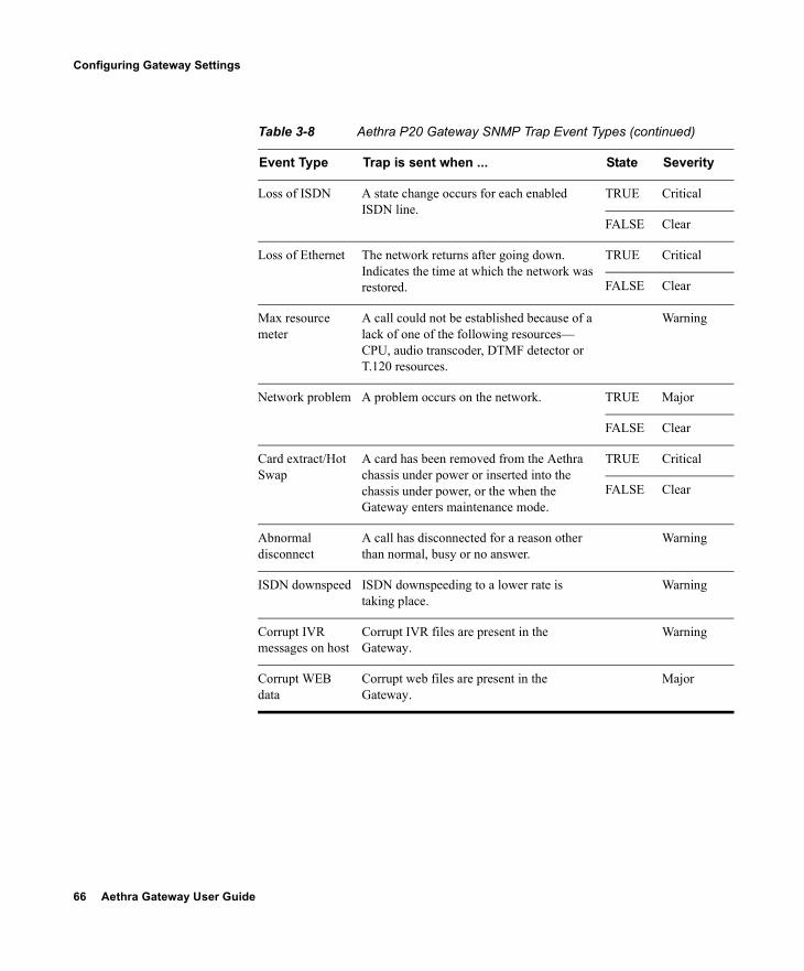
66 Aethra Gateway User Guide
Configuring Gateway Settings
Loss of ISDN A state change occurs for each enabled ISDN line.
TRUE Critical
FALSE Clear
Loss of Ethernet The network returns after going down. Indicates the time at which the network was restored.
TRUE Critical
FALSE Clear
Max resource meter
A call could not be established because of a lack of one of the following resources—CPU, audio transcoder, DTMF detector or T.120 resources.
Warning
Network problem A problem occurs on the network. TRUE Major
FALSE Clear
Card extract/Hot Swap
A card has been removed from the Aethra chassis under power or inserted into the chassis under power, or the when the Gateway enters maintenance mode.
TRUE Critical
FALSE Clear
Abnormal disconnect
A call has disconnected for a reason other than normal, busy or no answer.
Warning
ISDN downspeed ISDN downspeeding to a lower rate is taking place.
Warning
Corrupt IVR messages on host
Corrupt IVR files are present in the Gateway.
Warning
Corrupt WEB data
Corrupt web files are present in the Gateway.
Major
Table 3-8 Aethra P20 Gateway SNMP Trap Event Types (continued)
Event Type Trap is sent when ... State Severity
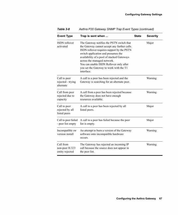
Configuring the Aethra Gateway 67
Configuring Gateway Settings
ISDN rollover activated
The Gateway notifies the PSTN switch that the Gateway cannot accept any further calls.ISDN rollover requires support by the PSTN switch application and presumes the availability of a pool of stacked Gateways across the managed network.You can enable ISDN Rollover only after you set the Gateway to work with the T1 interface.
Major
Call to peer rejected - trying alternate
A call to a peer has been rejected and the Gateway is searching for an alternate peer.
Warning
Call from peer rejected due to capacity
A call from a peer has been rejected because the Gateway does not have enough resources available.
Warning
Call to peer rejected by all listed peers
A call to a peer has been rejected by all listed peers.
Major
Call to peer failed - peer list empty
A call to a peer has failed because the peer list is empty.
Major
Incompatible sw version install
An attempt to burn a version of the Gateway software onto incompatible hardware occurs.
Warning
Call from non-peer H.323 entity rejected
The Gateway has rejected an incoming IP call because the source does not appear in the peer list.
Warning
Table 3-8 Aethra P20 Gateway SNMP Trap Event Types (continued)
Event Type Trap is sent when ... State Severity
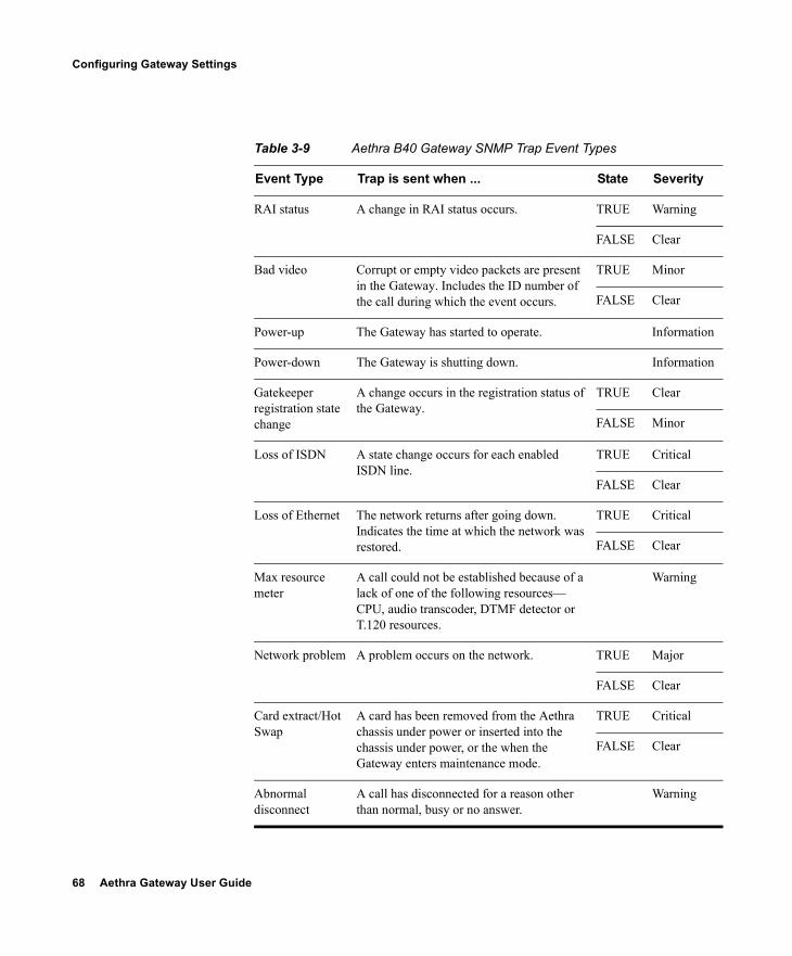
68 Aethra Gateway User Guide
Configuring Gateway Settings
Table 3-9 Aethra B40 Gateway SNMP Trap Event Types
Event Type Trap is sent when ... State Severity
RAI status A change in RAI status occurs. TRUE Warning
FALSE Clear
Bad video Corrupt or empty video packets are present in the Gateway. Includes the ID number of the call during which the event occurs.
TRUE Minor
FALSE Clear
Power-up The Gateway has started to operate. Information
Power-down The Gateway is shutting down. Information
Gatekeeper registration state change
A change occurs in the registration status of the Gateway.
TRUE Clear
FALSE Minor
Loss of ISDN A state change occurs for each enabled ISDN line.
TRUE Critical
FALSE Clear
Loss of Ethernet The network returns after going down. Indicates the time at which the network was restored.
TRUE Critical
FALSE Clear
Max resource meter
A call could not be established because of a lack of one of the following resources—CPU, audio transcoder, DTMF detector or T.120 resources.
Warning
Network problem A problem occurs on the network. TRUE Major
FALSE Clear
Card extract/Hot Swap
A card has been removed from the Aethra chassis under power or inserted into the chassis under power, or the when the Gateway enters maintenance mode.
TRUE Critical
FALSE Clear
Abnormal disconnect
A call has disconnected for a reason other than normal, busy or no answer.
Warning
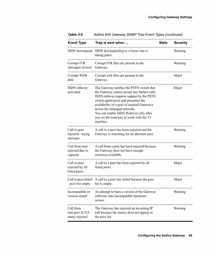
Configuring the Aethra Gateway 69
Configuring Gateway Settings
ISDN downspeed ISDN downspeeding to a lower rate is taking place.
Warning
Corrupt IVR messages on host
Corrupt IVR files are present in the Gateway.
Warning
Corrupt WEB data
Corrupt web files are present in the Gateway.
Major
ISDN rollover activated
The Gateway notifies the PSTN switch that the Gateway cannot accept any further calls.ISDN rollover requires support by the PSTN switch application and presumes the availability of a pool of stacked Gateways across the managed network.You can enable ISDN Rollover only after you set the Gateway to work with the T1 interface.
Major
Call to peer rejected - trying alternate
A call to a peer has been rejected and the Gateway is searching for an alternate peer.
Warning
Call from peer rejected due to capacity
A call from a peer has been rejected because the Gateway does not have enough resources available.
Warning
Call to peer rejected by all listed peers
A call to a peer has been rejected by all listed peers.
Major
Call to peer failed - peer list empty
A call to a peer has failed because the peer list is empty.
Major
Incompatible sw version install
An attempt to burn a version of the Gateway software onto incompatible hardware occurs.
Warning
Call from non-peer H.323 entity rejected
The Gateway has rejected an incoming IP call because the source does not appear in the peer list.
Warning
Table 3-9 Aethra B40 Gateway SNMP Trap Event Types (continued)
Event Type Trap is sent when ... State Severity
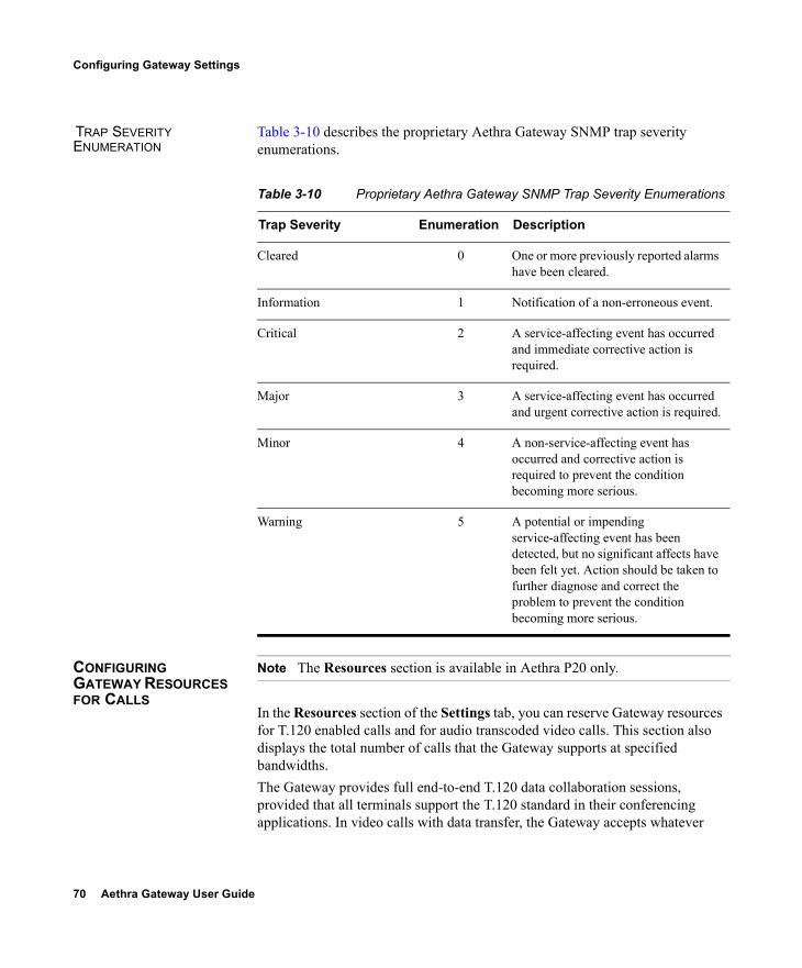
70 Aethra Gateway User Guide
Configuring Gateway Settings
TRAP SEVERITY ENUMERATION
Table 3-10 describes the proprietary Aethra Gateway SNMP trap severity enumerations.
CONFIGURING GATEWAY RESOURCES FOR CALLS
Note The Resources section is available in Aethra P20 only.
In the Resources section of the Settings tab, you can reserve Gateway resources for T.120 enabled calls and for audio transcoded video calls. This section also displays the total number of calls that the Gateway supports at specified bandwidths.The Gateway provides full end-to-end T.120 data collaboration sessions, provided that all terminals support the T.120 standard in their conferencing applications. In video calls with data transfer, the Gateway accepts whatever
Table 3-10 Proprietary Aethra Gateway SNMP Trap Severity Enumerations
Trap Severity Enumeration Description
Cleared 0 One or more previously reported alarms have been cleared.
Information 1 Notification of a non-erroneous event.
Critical 2 A service-affecting event has occurred and immediate corrective action is required.
Major 3 A service-affecting event has occurred and urgent corrective action is required.
Minor 4 A non-service-affecting event has occurred and corrective action is required to prevent the condition becoming more serious.
Warning 5 A potential or impending service-affecting event has been detected, but no significant affects have been felt yet. Action should be taken to further diagnose and correct the problem to prevent the condition becoming more serious.
Configuring the Aethra Gateway 71
Configuring Gateway Settings
bandwidth the ISDN connection defines for the data and dynamically adjusts the outgoing bandwidth used for data by using the MLP, HMLP and VarMLP formats.You can also configure the Gateway to prioritize the transcoding, giving preference to a particular codec that is applied to calls, thus optimizing the resource allocation utilized by each call. The Gateway supports up to 30 video calls on two B channels. If transcoding or T.120 capabilities are required, the Gateway has to reserve resources for these. The Gateway can differentiate between those calls that support T.120 and those that do not. When receiving calls, the Gateway can check whether you are reserving resources for transcoding or for T.120 capabilities.
Procedure
1 In the Gateway interface, on the sidebar, click Gateway (if not already selected).
2 Click the Settings tab.3 Click the Resources button.4 In the Maximum number of T.120 calls field, enter the
number of T.120 enabled calls that you want to reserve Gateway resources for. The maximum number is 18.
5 In the Maximum number of video calls with audio transcoding field, enter the number of audio transcoded video calls you want to reserve Gateway resources for. The maximum number is 20.
Note The term audio transcoded video calls refers to the process whereby an audio stream in a multimedia call is transcoded from one codec type to another.
6 In the Total call capacity: n calls of n Kbps field, choose a bandwidth.
7 Click Update total call capacity.The number of calls that the Gateway can support at that bandwidth automatically appears.
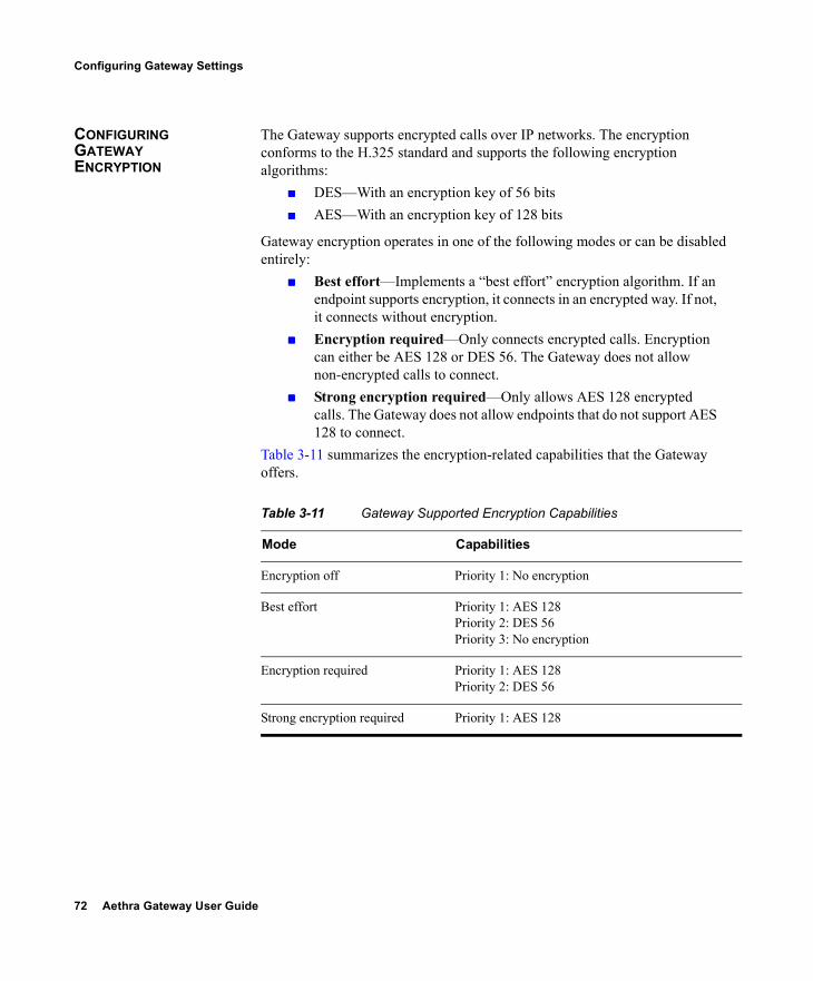
72 Aethra Gateway User Guide
Configuring Gateway Settings
CONFIGURING GATEWAY ENCRYPTION
The Gateway supports encrypted calls over IP networks. The encryption conforms to the H.325 standard and supports the following encryption algorithms:
DES—With an encryption key of 56 bits AES—With an encryption key of 128 bits
Gateway encryption operates in one of the following modes or can be disabled entirely:
Best effort—Implements a “best effort” encryption algorithm. If an endpoint supports encryption, it connects in an encrypted way. If not, it connects without encryption.
Encryption required—Only connects encrypted calls. Encryption can either be AES 128 or DES 56. The Gateway does not allow non-encrypted calls to connect.
Strong encryption required—Only allows AES 128 encrypted calls. The Gateway does not allow endpoints that do not support AES 128 to connect.
Table 3-11 summarizes the encryption-related capabilities that the Gateway offers.
Table 3-11 Gateway Supported Encryption Capabilities
Mode Capabilities
Encryption off Priority 1: No encryption
Best effort Priority 1: AES 128Priority 2: DES 56Priority 3: No encryption
Encryption required Priority 1: AES 128Priority 2: DES 56
Strong encryption required Priority 1: AES 128
Configuring the Aethra Gateway 73
Configuring Gateway Settings
The following channels support encryption: Audio channel Video Channel Far End Camera Control (FECC)
Note All channels (audio, video and FECC, incoming, outgoing) on the same call must have the same encryption levels. If the same encryption on all channels is not achieved, the call disconnects.
In the Security section of the Settings tab, you can configure Gateway encryption settings.
Procedure
1 In the Gateway interface, on the sidebar, click Gateway (if not already selected).
2 Click the Settings tab.3 Click the Security button.4 Select the Support encryption check box to enable Gateway
support for H.235 encryption for H.323 calls.5 In the Encryption mode field, choose one of the following
settings: Best effort Encryption required Strong encryption required
CONFIGURING ADVANCED SETTINGS
In the Advanced section of the Settings tab, you can configure, enable, and disable various advanced Gateway settings.
Procedure
1 In the Gateway interface, on the sidebar, click Gateway (if not already selected).
2 Click the Settings tab.
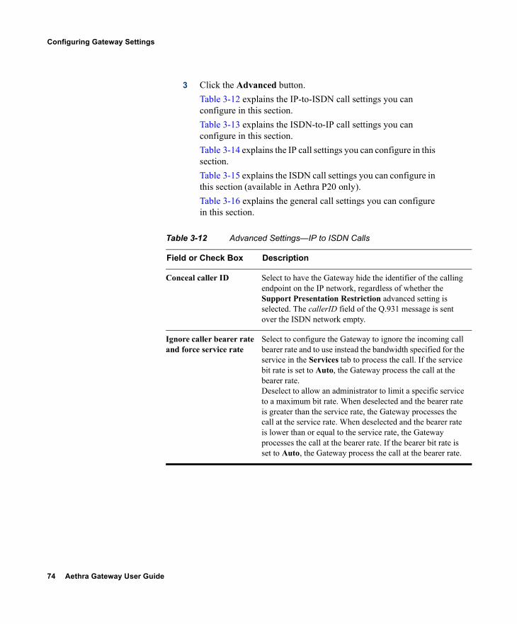
74 Aethra Gateway User Guide
Configuring Gateway Settings
3 Click the Advanced button.Table 3-12 explains the IP-to-ISDN call settings you can configure in this section.Table 3-13 explains the ISDN-to-IP call settings you can configure in this section.Table 3-14 explains the IP call settings you can configure in this section.Table 3-15 explains the ISDN call settings you can configure in this section (available in Aethra P20 only).Table 3-16 explains the general call settings you can configure in this section.
Table 3-12 Advanced Settings—IP to ISDN Calls
Field or Check Box Description
Conceal caller ID Select to have the Gateway hide the identifier of the calling endpoint on the IP network, regardless of whether the Support Presentation Restriction advanced setting is selected. The callerID field of the Q.931 message is sent over the ISDN network empty.
Ignore caller bearer rate and force service rate
Select to configure the Gateway to ignore the incoming call bearer rate and to use instead the bandwidth specified for the service in the Services tab to process the call. If the service bit rate is set to Auto, the Gateway process the call at the bearer rate.Deselect to allow an administrator to limit a specific service to a maximum bit rate. When deselected and the bearer rate is greater than the service rate, the Gateway processes the call at the service rate. When deselected and the bearer rate is lower than or equal to the service rate, the Gateway processes the call at the bearer rate. If the bearer bit rate is set to Auto, the Gateway process the call at the bearer rate.
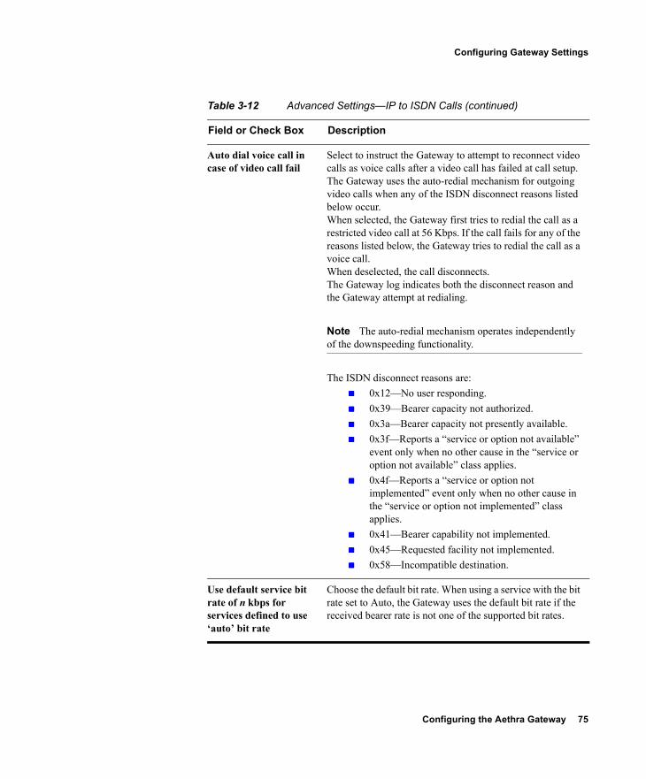
Configuring the Aethra Gateway 75
Configuring Gateway Settings
Auto dial voice call in case of video call fail
Select to instruct the Gateway to attempt to reconnect video calls as voice calls after a video call has failed at call setup. The Gateway uses the auto-redial mechanism for outgoing video calls when any of the ISDN disconnect reasons listed below occur.When selected, the Gateway first tries to redial the call as a restricted video call at 56 Kbps. If the call fails for any of the reasons listed below, the Gateway tries to redial the call as a voice call.When deselected, the call disconnects.The Gateway log indicates both the disconnect reason and the Gateway attempt at redialing.
Note The auto-redial mechanism operates independently of the downspeeding functionality.
The ISDN disconnect reasons are: 0x12—No user responding. 0x39—Bearer capacity not authorized. 0x3a—Bearer capacity not presently available. 0x3f—Reports a “service or option not available”
event only when no other cause in the “service or option not available” class applies.
0x4f—Reports a “service or option not implemented” event only when no other cause in the “service or option not implemented” class applies.
0x41—Bearer capability not implemented. 0x45—Requested facility not implemented. 0x58—Incompatible destination.
Use default service bit rate of n kbps for services defined to use ‘auto’ bit rate
Choose the default bit rate. When using a service with the bit rate set to Auto, the Gateway uses the default bit rate if the received bearer rate is not one of the supported bit rates.
Table 3-12 Advanced Settings—IP to ISDN Calls (continued)
Field or Check Box Description
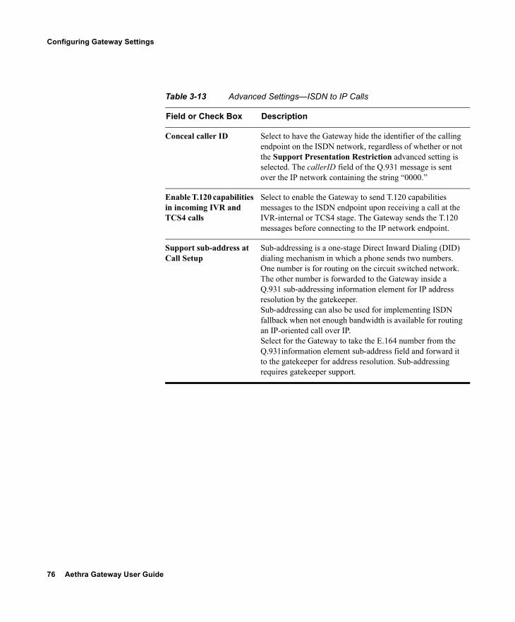
76 Aethra Gateway User Guide
Configuring Gateway Settings
Table 3-13 Advanced Settings—ISDN to IP Calls
Field or Check Box Description
Conceal caller ID Select to have the Gateway hide the identifier of the calling endpoint on the ISDN network, regardless of whether or not the Support Presentation Restriction advanced setting is selected. The callerID field of the Q.931 message is sent over the IP network containing the string “0000.”
Enable T.120 capabilities in incoming IVR and TCS4 calls
Select to enable the Gateway to send T.120 capabilities messages to the ISDN endpoint upon receiving a call at the IVR-internal or TCS4 stage. The Gateway sends the T.120 messages before connecting to the IP network endpoint.
Support sub-address at Call Setup
Sub-addressing is a one-stage Direct Inward Dialing (DID) dialing mechanism in which a phone sends two numbers. One number is for routing on the circuit switched network. The other number is forwarded to the Gateway inside a Q.931 sub-addressing information element for IP address resolution by the gatekeeper. Sub-addressing can also be used for implementing ISDN fallback when not enough bandwidth is available for routing an IP-oriented call over IP.Select for the Gateway to take the E.164 number from the Q.931information element sub-address field and forward it to the gatekeeper for address resolution. Sub-addressing requires gatekeeper support.
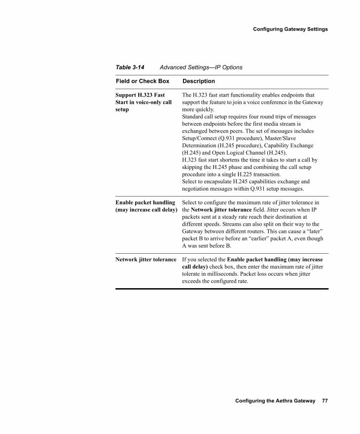
Configuring the Aethra Gateway 77
Configuring Gateway Settings
Table 3-14 Advanced Settings—IP Options
Field or Check Box Description
Support H.323 Fast Start in voice-only call setup
The H.323 fast start functionality enables endpoints that support the feature to join a voice conference in the Gateway more quickly.Standard call setup requires four round trips of messages between endpoints before the first media stream is exchanged between peers. The set of messages includes Setup/Connect (Q.931 procedure), Master/Slave Determination (H.245 procedure), Capability Exchange (H.245) and Open Logical Channel (H.245).H.323 fast start shortens the time it takes to start a call by skipping the H.245 phase and combining the call setup procedure into a single H.225 transaction. Select to encapsulate H.245 capabilities exchange and negotiation messages within Q.931 setup messages.
Enable packet handling (may increase call delay)
Select to configure the maximum rate of jitter tolerance in the Network jitter tolerance field. Jitter occurs when IP packets sent at a steady rate reach their destination at different speeds. Streams can also split on their way to the Gateway between different routers. This can cause a “later” packet B to arrive before an “earlier” packet A, even though A was sent before B.
Network jitter tolerance If you selected the Enable packet handling (may increase call delay) check box, then enter the maximum rate of jitter tolerate in milliseconds. Packet loss occurs when jitter exceeds the configured rate.
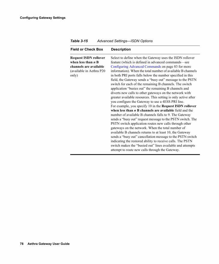
78 Aethra Gateway User Guide
Configuring Gateway Settings
Table 3-15 Advanced Settings—ISDN Options
Field or Check Box Description
Request ISDN rollover when less than n B channels are available (available in Aethra P20 only)
Select to define when the Gateway uses the ISDN rollover feature (which is defined in advanced commands—see Configuring Advanced Commands on page 83 for more information). When the total number of available B channels in both PRI ports falls below the number specified in this field, the Gateway sends a “busy out” message to the PSTN switch for each of the remaining B channels. The switch application “busies out” the remaining B channels and diverts new calls to other gateways on the network with greater available resources. This setting is only active after you configure the Gateway to use a 4ESS PRI line. For example, you specify 10 in the Request ISDN rollover when less than n B channels are available field and the number of available B channels falls to 9. The Gateway sends a “busy out” request message to the PSTN switch. The PSTN switch application routes new calls through other gateways on the network. When the total number of available B channels returns to at least 10, the Gateway sends a “busy out” cancellation message to the PSTN switch indicating the restored ability to receive calls. The PSTN switch makes the “busied out” lines available and attempts attempt to route new calls through the Gateway.
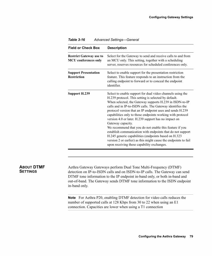
Configuring the Aethra Gateway 79
Configuring Gateway Settings
ABOUT DTMF SETTINGS
Aethra Gateway Gateways perform Dual Tone Multi-Frequency (DTMF) detection on IP-to-ISDN calls and on ISDN-to-IP calls. The Gateway can send DTMF tone information to the IP endpoint in-band only, or both in-band and out-of-band. The Gateway sends DTMF tone information to the ISDN endpoint in-band only.
Note For Aethra P20, enabling DTMF detection for video calls reduces the number of supported calls at 128 Kbps from 30 to 22 when using an E1 connection. Capacities are lower when using a T1 connection
Table 3-16 Advanced Settings—General
Field or Check Box Description
Restrict Gateway use to MCU conferences only
Select for the Gateway to send and receive calls to and from an MCU only. This setting, together with a scheduling server, reserves resources for scheduled conferences only.
Support Presentation Restriction
Select to enable support for the presentation restriction feature. This feature responds to an instruction from the calling endpoint to forward or to conceal the endpoint identifier.
Support H.239 Select to enable support for dual video channels using the H.239 protocol. This setting is selected by default.When selected, the Gateway supports H.239 in ISDN-to-IP calls and in IP-to-ISDN calls. The Gateway identifies the protocol version that an IP endpoint uses and sends H.239 capabilities only to those endpoints working with protocol version 4.0 or later. H.239 support has no impact on Gateway capacity.We recommend that you do not enable this feature if you establish communication with endpoints that do not support H.245 generic capabilities (endpoints based on H.323 version 2 or earlier) as this might cause the endpoints to fail upon receiving these capability exchanges.
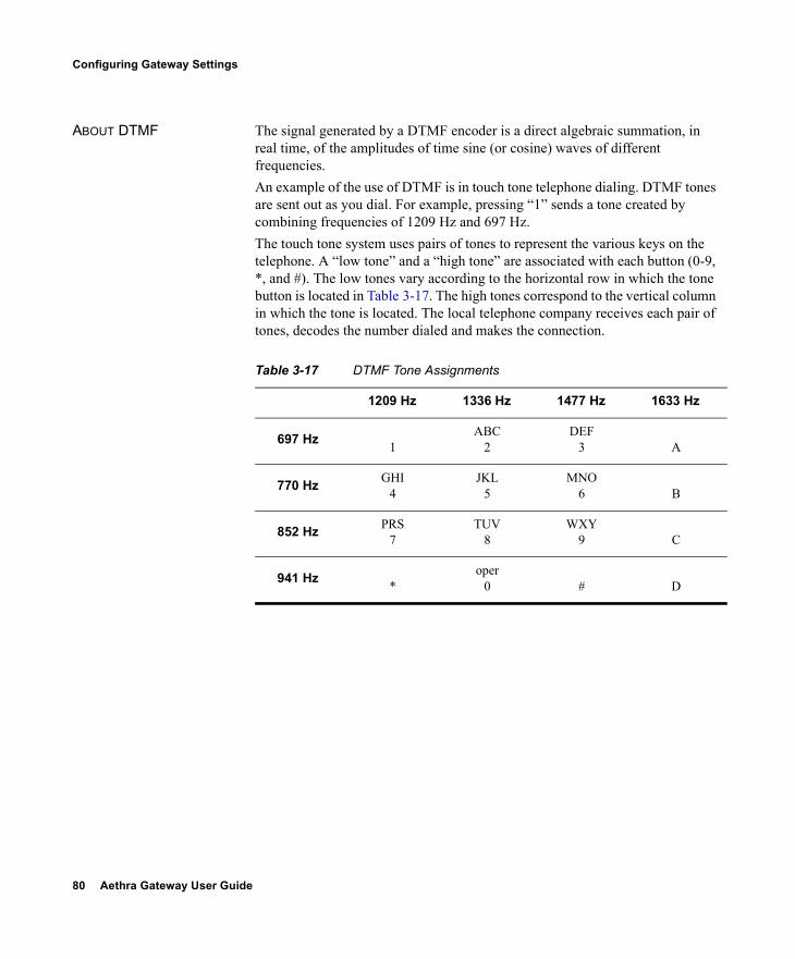
80 Aethra Gateway User Guide
Configuring Gateway Settings
ABOUT DTMF The signal generated by a DTMF encoder is a direct algebraic summation, in real time, of the amplitudes of time sine (or cosine) waves of different frequencies.An example of the use of DTMF is in touch tone telephone dialing. DTMF tones are sent out as you dial. For example, pressing “1” sends a tone created by combining frequencies of 1209 Hz and 697 Hz.The touch tone system uses pairs of tones to represent the various keys on the telephone. A “low tone” and a “high tone” are associated with each button (0-9, *, and #). The low tones vary according to the horizontal row in which the tone button is located in Table 3-17. The high tones correspond to the vertical column in which the tone is located. The local telephone company receives each pair of tones, decodes the number dialed and makes the connection. Table 3-17 DTMF Tone Assignments
1209 Hz 1336 Hz 1477 Hz 1633 Hz
697 Hz 1ABC
2DEF
3 A
770 Hz GHI4
JKL5
MNO6 B
852 Hz PRS7
TUV8
WXY9 C
941 Hz *oper
0 # D
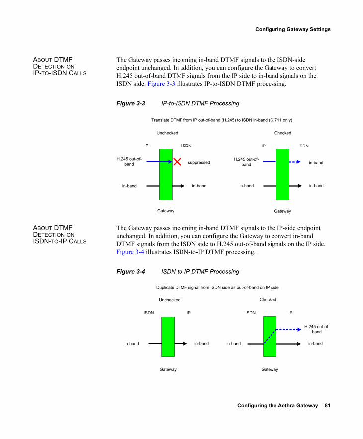
Configuring the Aethra Gateway 81
Configuring Gateway Settings
ABOUT DTMF DETECTION ON IP-TO-ISDN CALLS
The Gateway passes incoming in-band DTMF signals to the ISDN-side endpoint unchanged. In addition, you can configure the Gateway to convert H.245 out-of-band DTMF signals from the IP side to in-band signals on the ISDN side. Figure 3-3 illustrates IP-to-ISDN DTMF processing.
Figure 3-3 IP-to-ISDN DTMF Processing
ABOUT DTMF DETECTION ON ISDN-TO-IP CALLS
The Gateway passes incoming in-band DTMF signals to the IP-side endpoint unchanged. In addition, you can configure the Gateway to convert in-band DTMF signals from the ISDN side to H.245 out-of-band signals on the IP side. Figure 3-4 illustrates ISDN-to-IP DTMF processing.
Figure 3-4 ISDN-to-IP DTMF Processing
Gateway
IP ISDN
H.245 out-of-
band
in-band in-band
suppressed
Gateway
IP ISDN
H.245 out-of-
band
in-band in-band
in-band
Translate DTMF from IP out-of-band (H.245) to ISDN in-band (G.711 only)
Unchecked Checked
Gateway
ISDN IP
in-band in-band
Gateway
ISDN IP
H.245 out-of-
band
in-band in-band
Duplicate DTMF signal from ISDN side as out-of-band on IP side
Unchecked Checked
82 Aethra Gateway User Guide
Configuring Gateway Settings
CONFIGURING DTMF SETTINGS
You can enable DTMF detection and settings in the Advanced section of the Settings tab.
Procedure
1 In the Gateway interface, on the sidebar, click Gateway (if not already selected).
2 Click the Settings tab.3 Click the Advanced button.4 In the IP to ISDN Calls section of the PRI gateway and the
BRI Gateway, you can select the Translate DTMF from IP out-of-band (H.245) to ISDN in-band (G.711 only) check box. When selected, the Gateway performs the following: Converts H.245 out-of-band DTMF signals coming
from the H.323 IP-side endpoint to in-band signals on the ISDN side.
Passes incoming in-band DTMF signals to the ISDN-side endpoint unchanged.
This setting is selected by default. If deselected, the Gateway passes in-band DTMF signals to the ISDN-side endpoint unchanged.
5 In the ISDN to IP Calls section of the PRI gateway and the BRI Gateway, you can select the Duplicate DTMF signal from ISDN side as out-of-band on IP side check box. When selected, the Gateway performs the following: Converts in-band DTMF signals from the ISDN-side
endpoint to out-of-band H.245 signals if the IP-side endpoint is located on an H.323 network.
Passes incoming in-band DTMF signals to the IP-side endpoint unchanged.
This setting is selected by default. If deselected, the Gateway passes in-band DTMF signals to the IP-side endpoint unchanged. If you do select this setting, perform step 6.
6 In the Apply to field of the PRI gateway and the BRI Gateway, choose the type of calls to which ISDN-to-IP DTMF
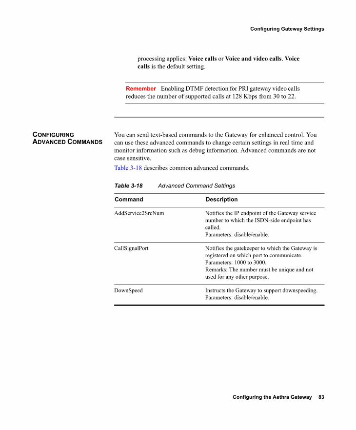
Configuring the Aethra Gateway 83
Configuring Gateway Settings
processing applies: Voice calls or Voice and video calls. Voice calls is the default setting.
Remember Enabling DTMF detection for PRI gateway video calls reduces the number of supported calls at 128 Kbps from 30 to 22.
CONFIGURING ADVANCED COMMANDS
You can send text-based commands to the Gateway for enhanced control. You can use these advanced commands to change certain settings in real time and monitor information such as debug information. Advanced commands are not case sensitive.Table 3-18 describes common advanced commands.
Table 3-18 Advanced Command Settings
Command Description
AddService2SrcNum Notifies the IP endpoint of the Gateway service number to which the ISDN-side endpoint has called.Parameters: disable/enable.
CallSignalPort Notifies the gatekeeper to which the Gateway is registered on which port to communicate.Parameters: 1000 to 3000.Remarks: The number must be unique and not used for any other purpose.
DownSpeed Instructs the Gateway to support downspeeding.Parameters: disable/enable.

84 Aethra Gateway User Guide
Configuring Gateway Settings
EnhancedBillingForVoiceCalls Instructs the Gateway to support the Aethra Aethra Gatekeeper CDR Real Connect Time field. Real Connect Time indicates the actual time at which an IP-to-ISDN voice call connects to the ISDN terminal. When disabled, the Aethra Gatekeeper uses the Connect Time field for CDR billing purposes. Connect Time indicates the time at which the Connect message is sent to the source endpoint. Parameters: disable/enable.Remarks: Default value is disable. Relevant to voice calls only. Operational only when the Gateway is registered to an Aethra Gatekeeper working in Routed Mode.
ForceG711ForMcu Instructs the Gateway to open only a G.711 channel in Gateway-to-MCU calls. Parameters: disable/enable.
NotifyLevel Changes the type and number of debug messages that are generated.Parameters: 0—Disables Gateway logs. 3 (default)—Fatal error (Gateway can no longer provide service), a problem affecting user functionality (for example, call connect failure or no resources available), or status prints for Customer Support use. 6—Debugging. 8—Extended debugging.Remarks: We recommend that you do not exceed a NotifyLevel of 6 as this might overload the system with a very large debug message output. Level 3 should be sufficient for normal usage.
Peer-to-Peer disconnect reason add Instructs the Gateway under which circumstances to reroute a call to different peer device.Parameters: Enter a number representing the required H.323 call disconnect reason, as listed in Table 3-6.
Table 3-18 Advanced Command Settings (continued)
Command Description
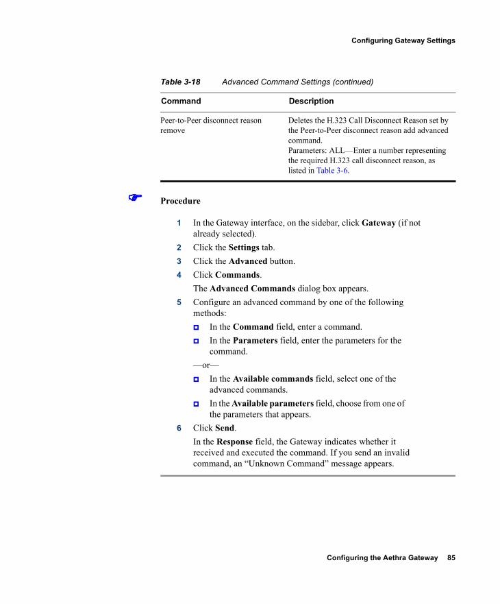
Configuring the Aethra Gateway 85
Configuring Gateway Settings
Procedure
1 In the Gateway interface, on the sidebar, click Gateway (if not already selected).
2 Click the Settings tab.3 Click the Advanced button.4 Click Commands.
The Advanced Commands dialog box appears.5 Configure an advanced command by one of the following
methods: In the Command field, enter a command. In the Parameters field, enter the parameters for the
command.—or— In the Available commands field, select one of the
advanced commands. In the Available parameters field, choose from one of
the parameters that appears.6 Click Send.
In the Response field, the Gateway indicates whether it received and executed the command. If you send an invalid command, an “Unknown Command” message appears.
Peer-to-Peer disconnect reason remove
Deletes the H.323 Call Disconnect Reason set by the Peer-to-Peer disconnect reason add advanced command. Parameters: ALL—Enter a number representing the required H.323 call disconnect reason, as listed in Table 3-6.
Table 3-18 Advanced Command Settings (continued)
Command Description
86 Aethra Gateway User Guide
About Gateway Services
ABOUT GATEWAY SERVICES
Gateway services are the mechanism that allows IP network endpoints to choose the type of connection they want to establish with a terminal or telephone on a circuit-switched network. A Gateway service defines the maximum bit rate for each channel, the media content of the stream (voice or data), and the mode of the call (restricted or non-restricted).A service prefix identifies a service. The service prefix is an identifier string that can have up to 31 characters. Valid characters are 0 to 9, pound (#), asterisk (*), or comma (,). You access a service by dialing the service prefix before the phone number of the destination. For example, 9* would be identified by the Gateway as a service prefix if you dialed 9*5673994.
Note If the Ignore caller bearer rate and force service rate setting in the Advanced section of the Settings tab is selected, a service uses the defined bit rate. If the Ignore caller bearer rate and force service rate setting is deselected, the bit rate defined in the service serves as the maximum limit for the service.
The Gateway has two types of services: default and user-defined. Default services come pre-configured on the Gateway. User-defined services are services that you can define at any time using the Gateway interface. Upon registration with a gatekeeper, the Gateway provides the gatekeeper with a list of Gateway services.The following topics discuss how you can configure services in the Services tab:
Viewing Existing Services on page 86 Adding or Editing Services on page 87 Deleting Gateway Services on page 89
VIEWING EXISTING SERVICES
The Services tab in the Gateway interface displays a list of currently defined services for the Gateway in a table format with the following columns and fields:
Prefix—Displays the prefix that identifies the service. Description—Description of the service. Call Type—Media type of the call. Bit Rate—Total bandwidth requested for the service.
Configuring the Aethra Gateway 87
About Gateway Services
PRI Port 1 or 2/BRI Port 1 to 4—Indicates whether or not the service is enabled for the specified port.
Total—Displays the total number of services currently defined in the Gateway.
ADDING OR EDITING SERVICES
In the Services tab, you can add a new service or edit an existing one.
Procedure
1 In the Gateway interface, on the sidebar, click Gateway (if not already selected).
2 Click the Services tab.3 To add a new service, click Add. To edit an existing service,
select it and then click Edit.4 In the Prefix field, enter or edit the prefix number of the
service. The prefix can be up to 31 characters long. Valid characters are 0 to 9 and pound sign (#), asterisk (*), and comma (,).
Note Since the comma cannot be used in the Party number field of the Aethra MCU Conference Control interface, we recommend that you do not use the comma as a prefix in Gateway fields.
5 In the Description field, enter or edit the description of the service (up to 31 characters in length).
6 In the Call type field, select the call type for this service: Video or Voice.
7 In the Bit rate field, select the maximum bit rate you want for this service. If you select Auto, the Gateway determines the
88 Aethra Gateway User Guide
About Gateway Services
ISDN call rate according to the bearer capability received in the setup message from the IP network endpoint.
Note The Auto setting is for video calls only.
If the IP network endpoint has a configured bit rate that is not one of the options listed in this field, the Gateway uses the default bit rate configured in the Default Service Bit Rate field in the Advanced section of the Settings tab.
Note If the Ignore caller bearer rate and force service rate field is selected when you define a bit rate for a service, the service uses the defined bit rate. If the Ignore caller bearer rate and force service rate is deselected, the bit rate you define serves as the maximum limit for that service.
Related Topics
Bonding Synchronization
BONDING SYNCHRONIZATION
The Advanced dialog box enables you to configure a bonding synchronization setting for the specified service.
Procedure
1 Send the ServiceOption advanced command with a parameter of enable to activate the Advanced button.For information on sending advanced commands, see Configuring Advanced Commands on page 83.
2 Click Advanced to configure bonding synchronization settings.The Advanced dialog box appears.
3 In the Bonding Synchronization field, choose a bonding synchronization setting. Select Prolong only for endpoints that use non-standard synchronization mechanisms.

Configuring the Aethra Gateway 89
Configuring Port Settings
4 Click OK to save your setting and close the Advanced dialog box.
5 Click the Port Specific tab.6 In the Enable service in ports section, select the BRI or PRI
ports that are enabled for this service.7 Click OK.
The Gateway interface uploads your settings to the services database.
DELETING GATEWAY SERVICES
In the Settings tab, you can delete existing services.
Procedure
1 In the Gateway interface, on the sidebar, click Gateway (if not already selected).
2 Click the Services tab.3 Select a service and click Delete.
CONFIGURING PORT SETTINGS
In the PRI Port or BRI Port tabs, you can configure physical line settings for Gateway ports. The following topics discuss the settings you can configure.
Configuring Basic Port Settings on page 90 Configuring Port Physical Interface Settings on page 91 About Advanced ISDN Settings for PRI Gateways on page 97 Configuring Port Call Policies on page 108 Configuring Port Supported Services on page 109
Note Some configuration options are unavailable in Gateways that support only one PRI port.

90 Aethra Gateway User Guide
Configuring Port Settings
CONFIGURING BASIC PORT SETTINGS
In the Basics section of the PRI Port or BRI Port tabs, you can configure basic settings for the specified port.
Note (PRI gateways only) A frame alignment failure message will appear when you enable a port that is not in use (no cable is attached to the PRI line connector).
Procedure
1 In the Gateway interface, on the sidebar, click Gateway (if not already selected).
2 Click the applicable PRI Port or BRI Port tab.3 Select the Port enabled check box to enable this port. For PRI
gateways, if this setting is deselected, the CD LED light on the rear panel of the Gateway is disabled.
4 (PRI gateways only) In the Port phone numbers section, choose one of the following option buttons: Single Number—Defines a single number for this
PRI port. Enter a phone number in the field. Range—In the two fields, enter a range of numbers for
this PRI line. If the line has a range of numbers, you only need to enter the digits necessary to indicate the range. For example, if the phone numbers assigned to this line are 6775380 to 6775411, enter 380-411. You can type a maximum of 31 digits in each text field.
5 (PRI gateways only—optional) In the Local Area Code field, enter the local area code for the phone numbers. You can enter up to 16 digits.
6 (PRI gateways only—optional) Select the Strip Local Area Code check box if you want the Gateway to strip local area codes for outbound calls to the ISDN network.
Note The type of line connected to this PRI or BRI port appears in the Physical standard field.
Configuring the Aethra Gateway 91
Configuring Port Settings
CONFIGURING PORT PHYSICAL INTERFACE SETTINGS
This section describes the available configuration options for Gateway ports. PRI Ports BRI Ports
PRI PORTS Note This section applies only to Aethra P20.
In the Physical Interface section of the PRI Port tabs, you can configure the physical line properties of the specified PRI port.
Procedure
1 In the Gateway interface, on the sidebar, click Gateway (if not already selected).
2 Click the applicable PRI Port tab.3 Click the Physical Interface button.4 Select the Same as Port check box if you want to duplicate
physical interface settings from another PRI port that you choose from the field. When selected, you cannot modify any settings in this section. This option is not available in Gateways that support only one PRI port.
5 In the Interface field, choose the line interface: T1 or E1.6 In the Country field, choose the nation where the ISDN
service is installed.7 In the Signaling protocol field, choose the signaling protocol
used to set up and tear down the calls through the signaling (D) channel. Depending on the interface used, different signaling protocols are available.
8 In the Network access field, choose the Gateway national access type: TE (Terminal Equipment) or NT (Network Terminator) device.
9 In the Clock source field, choose the Gateway clock source: Master (the Gateway provides the clock signal)
92 Aethra Gateway User Guide
Configuring Port Settings
Slave (the Gateway receives the clock signal)10 In the Line Build Out field, choose Long Haul or Short
Haul.
Note You can configure this setting only if you select Japan in the Country field. Skip to step 4 otherwise.
.
Related Topics
Configuring Fractional Channels Configuring Line Coding, Framing and Signaling Type
CONFIGURING FRACTIONAL CHANNELS
In the Physical Interface section of the PRI Port tabs, you can configure fractional channels as part of the physical line properties of the specified PRI port.
Procedure
1 In the Gateway interface, on the sidebar, click Gateway (if not already selected).
2 Click the applicable PRI Port tab.3 Click the Physical Interface button.4 Click Fractional to select fractional channels.
The Fractional dialog box appears.5 Select the Fractional line check box to enable the fractional
selection of channels.6 In the Select the channels field, select the check boxes for the
individual channels you want to use for fractional E1 or T1
Configuring the Aethra Gateway 93
Configuring Port Settings
distribution. The table contains 24 check boxes for T1 or 31 check boxes for E1.
Note You cannot select channel 24 of the T1 settings and channel 16 of the E1 settings. These are reserved as the signaling (D) channels that are essential for communication.
Note You can click Select All to select all fractional channels or Deselect All to deselect all fractional channels.
7 Click OK to close the Fractional dialog box.
CONFIGURING LINE CODING, FRAMING AND SIGNALING TYPE
In the Physical Interface section of the PRI Port tabs, you can configure coding, framing, and signaling type settings as part of the physical line properties of the specified PRI port.
Procedure
1 In the Gateway interface, on the sidebar, click Gateway (if not already selected).
2 Click the applicable PRI Port tab.3 Click the Physical Interface button.4 Click Advanced to configure line coding, framing, and
signaling type.The Advanced dialog box appears.
5 In the Line coding field, choose the type of modulation used to encode the data.
6 In the Framing field, choose the framing and error detection method.
Note The ESF CRC6JT framing option is available only if you select Japan in the Country field and Long Haul in the Line Build Out field.
94 Aethra Gateway User Guide
Configuring Port Settings
7 In the Signaling type field, choose the signaling type.8 Click OK to close the Advanced dialog box.
BRI PORTS Note This section applies only to Aethra B40.
In the Physical Interface section of the BRI Port tabs, you can configure the physical line properties of the specified BRI port.
Procedure
1 In the Gateway interface, on the sidebar, click Gateway (if not already selected).
2 Click the applicable BRI Port tab.3 Click the Physical Interface button.4 Select the Same as Port check box if you want to duplicate
physical interface settings from another BRI port that you choose from the field. When selected, you cannot modify the Signaling Protocol or Country settings. This setting is selected by default.
5 In the Country field, choose the country where the ISDN service is installed.
6 In the Signaling Protocol field, choose the signaling protocol used to setup and tear down calls through the signaling (D) channel. Depending on the interface used, different signaling protocols are available for selection.
7 In the PCM Audio Format field, choose the desired G.711 audio standard: A-Low or U-Low.
Note You can only configure this setting if you select Taiwan in the Country field. Skip to step 8 otherwise.
8 In the Directory Numbers section, enter the phone numbers for the BRI line in the Number 1 and Number 2 fields.
Configuring the Aethra Gateway 95
Configuring Port Settings
9 Click Advanced to enable or disable alerting, Layer 1 line hunting, or configure a static Terminal Equipment Identifier (TEI).The Advanced dialog box appears.
10 Select the Enable Alerting check box for the Gateway to connect a voice call that is not rejected (instead of sending alert messages to the caller).The alerting feature is relevant for incoming voice calls routed directly to an endpoint (through DID) or to a default extension. When you select this option, the Gateway sends an alert message to the dialing ISDN terminal if the call is not connected within a few seconds. This informs the ISDN terminal that the call is not yet connected to the local IP endpoint. As a result, the ISDN terminal continues to hear a ringing sound until the Gateway connects to the call.
Note The Gateway connects the call even if the endpoint on the local IP network has not yet accepted it. If the IP endpoint does not accept the call, the call is rejected and immediately disconnects from the ISDN terminal.
This setting is selected by default. Deselect it to prevent the Gateway from sending an alert message.
11 Select the Enable Layer 1 Line Hunting check box if you do not want the Gateway to hunt BRI lines whose Layer 1 is not activated. This setting is deselected by default.
Note In European networks, Layer 1 is usually only activated during a call. In such a system, Layer 1 line hunting is not effective and should not be enabled. However, when the Gateway BRI port is connected to a private branch exchange (PBX) for some PBXs, Layer 1 always activates.
96 Aethra Gateway User Guide
Configuring Port Settings
12 Select the Enable static TEI check box to configure a static TEI. TEI values are supplied by the telecom company. If you select this option, perform step 13. Otherwise, skip to step 14.
Note You can only configure this setting if you select 5ESS PTP or ETSI PTP in the Signaling Protocol field of the Physical Interface section.
13 In the TEI Value (0-63) field, enter a value from 0 to 63 for this BRI line.
14 Click OK to upload your changes to the Gateway database and close the Advanced dialog box.
Related Topics
Configuring Service Profile Identification (SPID) Values
CONFIGURING SERVICE PROFILE IDENTIFICATION (SPID) VALUES
In the Physical Interface section of the BRI Port tabs, you can configure Service Profile Identification (SPID) values as part of the physical line properties of the specified BRI port.
Procedure
1 In the Gateway interface, on the sidebar, click Gateway (if not already selected).
2 Click the applicable BRI Port tab.3 Click the Physical Interface button.4 Click SPIDs to configure Service Profile Identification (SPID)
values for this BRI line. The SPID value is provided by the telecom company and indicates which services a specified BRI
Configuring the Aethra Gateway 97
Configuring Port Settings
line supports (for example, phone, fax, or videoconferencing facilities).
Note You can only configure SPID values if you select DMS100, National ISDN, or 5ESS Custom/Multipoint options in the Signaling Protocol field of the Physical Interface section, and when the Country field is set to US. Skip to step step 9 otherwise.
The SPIDs dialog box appears.5 In the Number of SPIDs field, choose the required number of
SPID values.6 In the SPID 1 field, enter the first SPID value.7 In the SPID 2 field, enter the second SPID value.8 Click OK to upload these changes to the Gateway database and
close the SPIDs dialog box.
ABOUT ADVANCED ISDN SETTINGS FOR PRI GATEWAYS
Note This section applies only to Aethra P20.
In the Advanced ISDN section of the PRI Port tabs, you can view and configure ISDN settings for Aethra P20. Table 3-19 explains the information that this tab displays.
Table 3-19 Advanced ISDN Tab Details
Column or Field Description
Prefix Displays the prefix of the advanced ISDN entry.
Description Displays a brief description of the advanced ISDN entry.
NPI Displays the Numbering Plan Identification (NPI) classification for the ISDN phone number.
TON Displays the Type of Number (TON) code for the advanced ISDN entry.

98 Aethra Gateway User Guide
Configuring Port Settings
The following topics discuss how you can configure Advanced ISDN Settings: About NSF Settings on page 98 Adding or Editing ISDN Information Elements on page 104 Deleting ISDN Information Elements on page 108
Note You can select the Same as Port check box and select another PRI port to duplicate advanced ISDN settings from that port. When you select this option, you cannot make any edits to the configuration settings. This option is unavailable in Gateway that support only one PRI port.
ABOUT NSF SETTINGS The NSF Information Element (IE) feature enables system administrators to coordinate network and service requirements with service providers. Service providers supply the information that you enter in the NSF Configuration dialog box. System administrators can either select any of the pre-configured NSF settings, or choose to configure their own NSF Information Element using service provider information.
NSF Indicates whether the Network Specific Facility feature is enabled or disabled for the Advanced ISDN entry.
Max Digits Displays the maximum number of digits allowed for outbound dialing.
DN Manipulation Indicates whether advanced ISDN prefix number is enabled. For default prefix entries where TON is local, this field indicates whether the DN Manipulation setting is set to Append Local Area Code in the Add or Edit ISDN Information Elements dialog box (see Adding or Editing ISDN Information Elements on page 104 for more information).
Total Displays the total number of ISDN information elements currently listed in the Gateway database.
Table 3-19 Advanced ISDN Tab Details (continued)
Column or Field Description

Configuring the Aethra Gateway 99
Configuring Port Settings
You can specify the following information in the NSF: The service providers with which you want their network to work. The specific network plan and equipment with which you want your
network to work (for example, switches and bandwidth). The specific services available to their network (for example,1-800
phone numbers).Instructions are contained in the NSF IE fields of outgoing Q.931 setup messages in the format shown in Figure 3-5.
Figure 3-5 Network Specific Facility Information Element Format
NSF Information Elements contain a number of configurable Octet fields. The values entered in these fields represent instructions contained in outgoing Q.931 Setup messages. Figure 3-5 represents the format of such instructions. Table 3-20 describes the function of each of the Octet fields.
Table 3-20 Octet Field Functions
Octet Function
Octet 3 Octet 3 represents the total number of Octet 3.X fields required for the specific information element, including the Octet 3 field itself.
Network Specific Facilities
Information Element identifier
Length of network specific facilities contents
Length of network identification
1ext
0spare
Parameterized/Binary
0spare
Type of network identification Network identification plan
Network Identification (IA5 characters)
1Exp
Feature/Service
8 7 6 5 4 3 2 1
0 1 0 0 0 0 00
Facility coding value
Parameterized Field
Octet 1
Octet 2
Octet 3
Octet 3.1
Octet 3.2
Octet 4
Octet 5
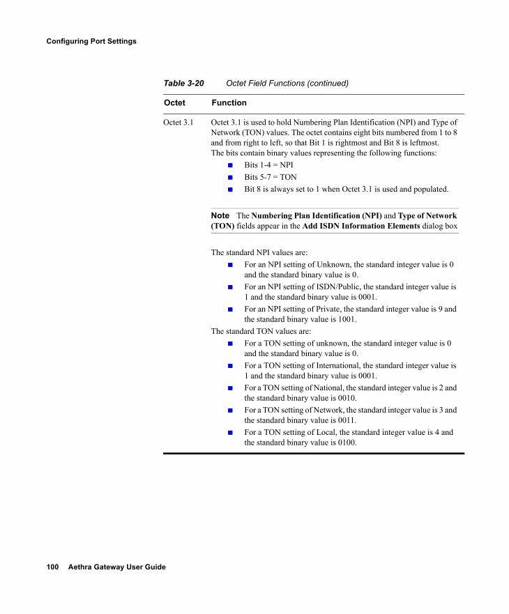
100 Aethra Gateway User Guide
Configuring Port Settings
Octet 3.1 Octet 3.1 is used to hold Numbering Plan Identification (NPI) and Type of Network (TON) values. The octet contains eight bits numbered from 1 to 8 and from right to left, so that Bit 1 is rightmost and Bit 8 is leftmost.The bits contain binary values representing the following functions:
Bits 1-4 = NPI Bits 5-7 = TON Bit 8 is always set to 1 when Octet 3.1 is used and populated.
Note The Numbering Plan Identification (NPI) and Type of Network (TON) fields appear in the Add ISDN Information Elements dialog box
The standard NPI values are: For an NPI setting of Unknown, the standard integer value is 0
and the standard binary value is 0. For an NPI setting of ISDN/Public, the standard integer value is
1 and the standard binary value is 0001. For an NPI setting of Private, the standard integer value is 9 and
the standard binary value is 1001.The standard TON values are:
For a TON setting of unknown, the standard integer value is 0 and the standard binary value is 0.
For a TON setting of International, the standard integer value is 1 and the standard binary value is 0001.
For a TON setting of National, the standard integer value is 2 and the standard binary value is 0010.
For a TON setting of Network, the standard integer value is 3 and the standard binary value is 0011.
For a TON setting of Local, the standard integer value is 4 and the standard binary value is 0100.
Table 3-20 Octet Field Functions (continued)
Octet Function
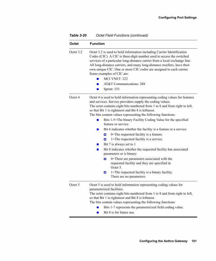
Configuring the Aethra Gateway 101
Configuring Port Settings
Octet 3.2 Octet 3.2 is used to hold information including Carrier Identification Codes (CIC). A CIC is three-digit number used to access the switched services of a particular long-distance carrier from a local exchange line. All long-distance carriers, and many long-distance resellers, have their own unique CIC. One or more CIC codes are assigned to each carrier. Some examples of CIC are:
MCI VNET: 222 AT&T Communications: 288 Sprint: 333
Octet 4 Octet 4 is used to hold information representing coding values for features and services. Service providers supply the coding values. The octet contains eight bits numbered from 1 to 8 and from right to left, so that Bit 1 is rightmost and Bit 8 is leftmost.The bits contain values representing the following functions:
Bits 1-5=The binary Facility Coding Value for the specified feature or service.
Bit 6 indicates whether the facility is a feature or a service: 0=The requested facility is a feature. 1=The requested facility is a service.
Bit 7 is always set to 1 Bit 8 indicates whether the requested facility has associated
parameters or is binary: 0=There are parameters associated with the
requested facility and they are specified in Octet 5.
1=The requested facility is a binary facility. There are no parameters.
Octet 5 Octet 5 is used to hold information representing coding values for parameterized facilities.The octet contains eight bits numbered from 1 to 8 and from right to left, so that Bit 1 is rightmost and Bit 8 is leftmost.The bits contain values representing the following functions:
Bits 1-7 represents the parameterized field coding value. Bit 8 is for future use.
Table 3-20 Octet Field Functions (continued)
Octet Function
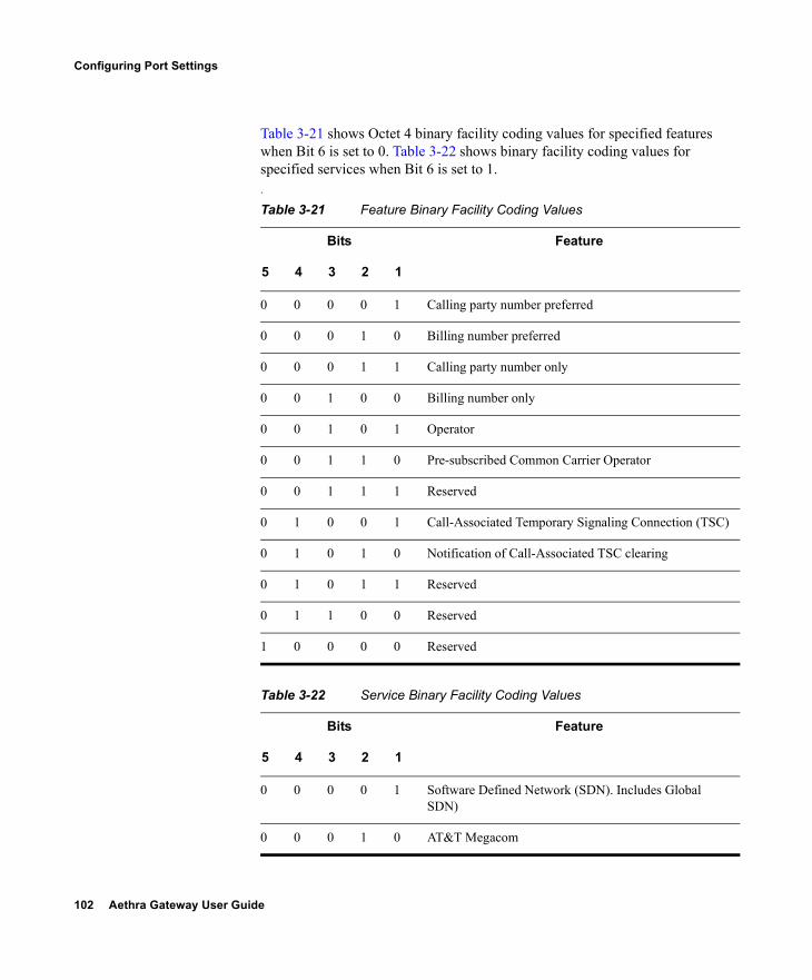
102 Aethra Gateway User Guide
Configuring Port Settings
Table 3-21 shows Octet 4 binary facility coding values for specified features when Bit 6 is set to 0. Table 3-22 shows binary facility coding values for specified services when Bit 6 is set to 1..
Table 3-21 Feature Binary Facility Coding Values
Bits Feature
5 4 3 2 1
0 0 0 0 1 Calling party number preferred
0 0 0 1 0 Billing number preferred
0 0 0 1 1 Calling party number only
0 0 1 0 0 Billing number only
0 0 1 0 1 Operator
0 0 1 1 0 Pre-subscribed Common Carrier Operator
0 0 1 1 1 Reserved
0 1 0 0 1 Call-Associated Temporary Signaling Connection (TSC)
0 1 0 1 0 Notification of Call-Associated TSC clearing
0 1 0 1 1 Reserved
0 1 1 0 0 Reserved
1 0 0 0 0 Reserved
Table 3-22 Service Binary Facility Coding Values
Bits Feature
5 4 3 2 1
0 0 0 0 1 Software Defined Network (SDN). Includes Global SDN)
0 0 0 1 0 AT&T Megacom
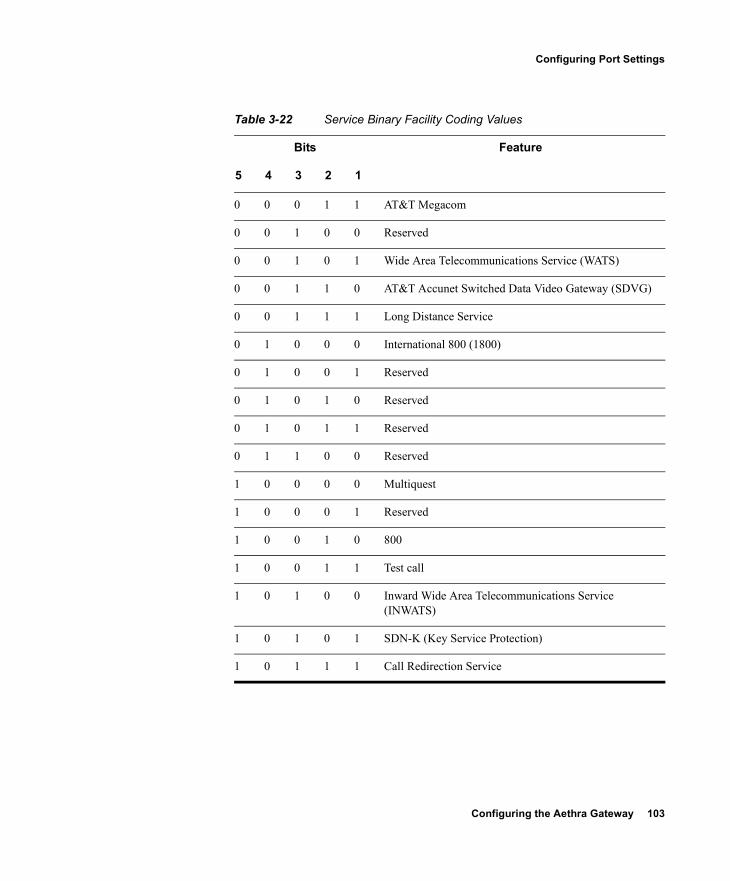
Configuring the Aethra Gateway 103
Configuring Port Settings
0 0 0 1 1 AT&T Megacom
0 0 1 0 0 Reserved
0 0 1 0 1 Wide Area Telecommunications Service (WATS)
0 0 1 1 0 AT&T Accunet Switched Data Video Gateway (SDVG)
0 0 1 1 1 Long Distance Service
0 1 0 0 0 International 800 (1800)
0 1 0 0 1 Reserved
0 1 0 1 0 Reserved
0 1 0 1 1 Reserved
0 1 1 0 0 Reserved
1 0 0 0 0 Multiquest
1 0 0 0 1 Reserved
1 0 0 1 0 800
1 0 0 1 1 Test call
1 0 1 0 0 Inward Wide Area Telecommunications Service (INWATS)
1 0 1 0 1 SDN-K (Key Service Protection)
1 0 1 1 1 Call Redirection Service
Table 3-22 Service Binary Facility Coding Values
Bits Feature
5 4 3 2 1
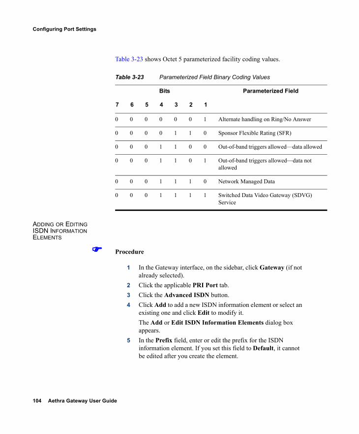
104 Aethra Gateway User Guide
Configuring Port Settings
Table 3-23 shows Octet 5 parameterized facility coding values.
ADDING OR EDITING ISDN INFORMATION ELEMENTS
Procedure
1 In the Gateway interface, on the sidebar, click Gateway (if not already selected).
2 Click the applicable PRI Port tab.3 Click the Advanced ISDN button.4 Click Add to add a new ISDN information element or select an
existing one and click Edit to modify it.The Add or Edit ISDN Information Elements dialog box appears.
5 In the Prefix field, enter or edit the prefix for the ISDN information element. If you set this field to Default, it cannot be edited after you create the element.
Table 3-23 Parameterized Field Binary Coding Values
Bits Parameterized Field
7 6 5 4 3 2 1
0 0 0 0 0 0 1 Alternate handling on Ring/No Answer
0 0 0 0 1 1 0 Sponsor Flexible Rating (SFR)
0 0 0 1 1 0 0 Out-of-band triggers allowed—data allowed
0 0 0 1 1 0 1 Out-of-band triggers allowed—data not allowed
0 0 0 1 1 1 0 Network Managed Data
0 0 0 1 1 1 1 Switched Data Video Gateway (SDVG) Service
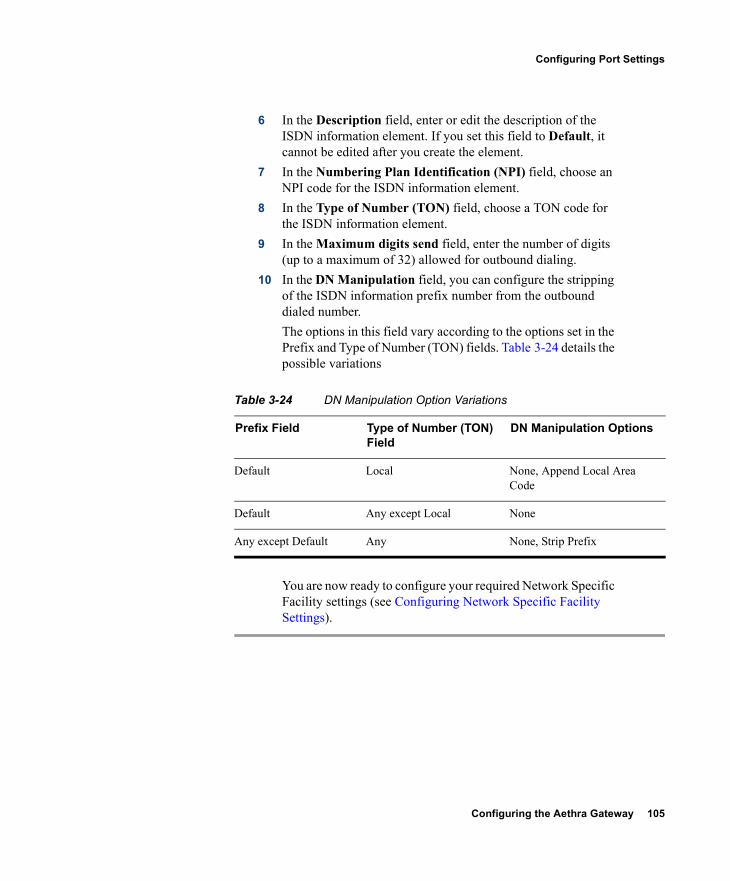
Configuring the Aethra Gateway 105
Configuring Port Settings
6 In the Description field, enter or edit the description of the ISDN information element. If you set this field to Default, it cannot be edited after you create the element.
7 In the Numbering Plan Identification (NPI) field, choose an NPI code for the ISDN information element.
8 In the Type of Number (TON) field, choose a TON code for the ISDN information element.
9 In the Maximum digits send field, enter the number of digits (up to a maximum of 32) allowed for outbound dialing.
10 In the DN Manipulation field, you can configure the stripping of the ISDN information prefix number from the outbound dialed number.The options in this field vary according to the options set in the Prefix and Type of Number (TON) fields. Table 3-24 details the possible variations
You are now ready to configure your required Network Specific Facility settings (see Configuring Network Specific Facility Settings).
Table 3-24 DN Manipulation Option Variations
Prefix Field Type of Number (TON) Field
DN Manipulation Options
Default Local None, Append Local Area Code
Default Any except Local None
Any except Default Any None, Strip Prefix
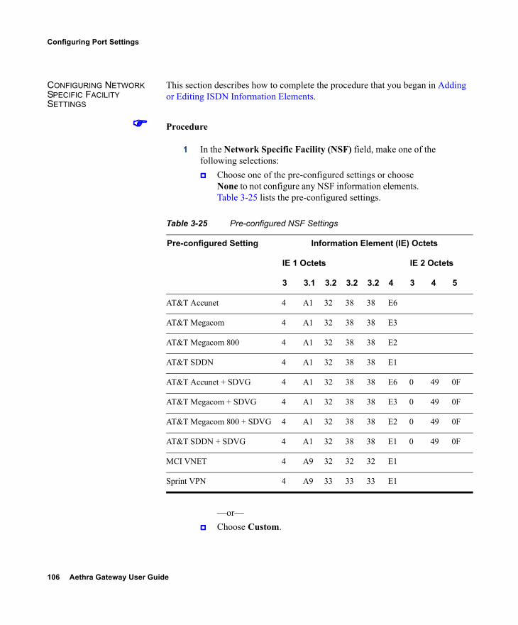
106 Aethra Gateway User Guide
Configuring Port Settings
CONFIGURING NETWORK SPECIFIC FACILITY SETTINGS
This section describes how to complete the procedure that you began in Adding or Editing ISDN Information Elements.
Procedure
1 In the Network Specific Facility (NSF) field, make one of the following selections: Choose one of the pre-configured settings or choose
None to not configure any NSF information elements. Table 3-25 lists the pre-configured settings.
—or— Choose Custom.
Table 3-25 Pre-configured NSF Settings
Pre-configured Setting Information Element (IE) Octets
IE 1 Octets IE 2 Octets
3 3.1 3.2 3.2 3.2 4 3 4 5
AT&T Accunet 4 A1 32 38 38 E6
AT&T Megacom 4 A1 32 38 38 E3
AT&T Megacom 800 4 A1 32 38 38 E2
AT&T SDDN 4 A1 32 38 38 E1
AT&T Accunet + SDVG 4 A1 32 38 38 E6 0 49 0F
AT&T Megacom + SDVG 4 A1 32 38 38 E3 0 49 0F
AT&T Megacom 800 + SDVG 4 A1 32 38 38 E2 0 49 0F
AT&T SDDN + SDVG 4 A1 32 38 38 E1 0 49 0F
MCI VNET 4 A9 32 32 32 E1
Sprint VPN 4 A9 33 33 33 E1
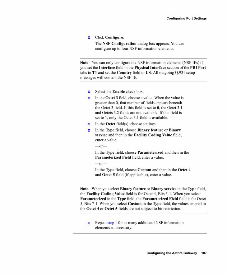
Configuring the Aethra Gateway 107
Configuring Port Settings
Click Configure.The NSF Configuration dialog box appears. You can configure up to four NSF information elements.
Note You can only configure the NSF information elements (NSF IEs) if you set the Interface field in the Physical Interface section of the PRI Port tabs to T1 and set the Country field to US. All outgoing Q.931 setup messages will contain the NSF IE.
Select the Enable check box. In the Octet 3 field, choose a value. When the value is
greater than 0, that number of fields appears beneath the Octet 3 field. If this field is set to 0, the Octet 3.1 and Octets 3.2 fields are not available. If this field is set to 1, only the Octet 3.1 field is available.
In the Octet field(s), choose settings. In the Type field, choose Binary feature or Binary
service and then in the Facility Coding Value field, enter a value.—or—In the Type field, choose Parameterized and then in the Parameterized Field field, enter a value.—or—In the Type field, choose Custom and then in the Octet 4 and Octet 5 field (if applicable), enter a value.
Note When you select Binary feature or Binary service in the Type field, the Facility Coding Value field is for Octet 4, Bits 5-1. When you select Parameterized in the Type field, the Parameterized Field field is for Octet 5, Bits 7-1. When you select Custom in the Type field, the values entered in the Octet 4 or Octet 5 fields are not subject to bit restriction.
Repeat step 1 for as many additional NSF information elements as necessary.
108 Aethra Gateway User Guide
Configuring Port Settings
DELETING ISDN INFORMATION ELEMENTS
In the Advanced ISDN section of the PRI Port tabs, you can delete an ISDN information element.
Procedure
1 In the Gateway interface, on the sidebar, click Gateway (if not already selected).
2 Click the applicable PRI Port tab.3 Click the Advanced ISDN button.4 Select an ISDN information element and click Delete.
CONFIGURING PORT CALL POLICIES
In the Call Policies section of the PRI Port or BRI Port tabs, you can configure the incoming call routing methods available in the Gateway for each specified port. You can define each port with different settings.
Procedure
1 In the Gateway interface, on the sidebar, click Gateway (if not already selected).
2 Click the applicable PRI Port or BRI Port tab.3 Click the Call Policies button.4 Select the Same as Port check box to duplicate call policies
settings from another Gateway port that you choose from the field. When selected, you cannot modify any settings in this section. This option is unavailable in Gateways that support only one PRI port.
5 In the Enable inbound routing methods section, you can select incoming call routing methods in the following order of priority: DID—When selected, enables Direct Inward Dialing
to an endpoint. TCS4—When selected, enables TCS4 dialing. This
setting does not apply to voice calls. IVR—When selected, enables the Interactive Voice
Response operator.
Configuring the Aethra Gateway 109
Configuring Port Settings
Default extension—When selected, enables the use of the default extension number that you enter in the field.
6 Select the Overlap Receiving check box to enable overlap receiving functionality. In this functionality, the Gateway can receive consecutive digits until the dialing is complete, instead of receiving the entire phone number as a block of digits. The Gateway recognizes that an overlap receiving dialing is completed when it receives a fixed, predefined, incoming number of digits. If the Gateway receives a complete indication notification from the switch (PSTN) or a timeout before all the digits have been dialed, the call might connect to a different address or rejected. If you select this setting, perform step 7, otherwise skip to step 8.
7 In the Incoming number of digits field, enter the number of digits you want the Gateway to expect during overlap receiving. The Gateway waits until this number of specified digits is received and then processes the whole number. You can enter any value up to 32.
8 In the Outgoing Calling Party Number field, enter a number that the Gateway automatically provides if the calling IP network endpoint does not provide a calling party number. Valid digits are 0 through 9 You can enter up to 11 digits.
CONFIGURING PORT SUPPORTED SERVICES
In the Supported Services section of the PRI Port or BRI Port tabs, you can enable or disable specific Gateway services on each port. The Supported Services section displays the following information in table form:
Prefix—Displays the prefix for this service. Description—Displays a brief description of the service. Call Type—Displays the call media type: Voice or Video. Bit Rate—Displays the maximum total bit rate allowed for this
service. Support—Displays the status of the service: enabled or
disabled.
110 Aethra Gateway User Guide
Viewing Call Information
Procedure
1 In the Gateway interface, on the sidebar, click Gateway (if not already selected).
2 Click the applicable PRI Port or BRI Port tab.3 Click the Supported Services button.4 Select the Same as Port check box if you want to duplicate
settings from another Gateway port that you choose from the field. When selected, you cannot modify any settings in this section. This option is unavailable in Gateways that support only one PRI port.
5 To enable or disable a service for this port, select it and click Enable or Disable.
VIEWING CALL INFORMATION
The Calls tab displays a list of the calls currently defined in the Gateway and the basic details of each call. The Calls tab displays the following information in table format:
Call ID—Displays the call identifier. Source Party Number—Displays the alias that identifies the source
endpoint of the call. Destination Party Number—Displays the alias that identifies the
destination endpoint of the call. Start Time—Displays the time at which the call began. Total Call Bandwidth—Displays the total bandwidth (in Kbps) used
for this call on both sides. Encryption—Indicates the level of encryption currently in use for
the specified participant: best effort, encryption required, or strong encryption required.
Total—Field indicates the total number of calls currently defined in the Gateway.
The following topics discuss the tasks you can perform in this tab: Refreshing Call Information on page 111 Viewing Call Details on page 111 Disconnecting Calls on page 113
Configuring the Aethra Gateway 111
Viewing Call Information
REFRESHING CALL INFORMATION
You can configure the Gateway interface to refresh information that appears in the Calls tab every ten seconds.
Procedure
1 In the Gateway interface, on the sidebar, click Gateway (if not already selected).
2 In the Calls tab, select the Auto Refresh check box.
VIEWING CALL DETAILS In the Calls tab, you can view detailed information for each call currently defined in the Gateway.
Procedure
1 In the Gateway interface, on the sidebar, click Gateway (if not already selected).
2 In the Calls tab, select a call and click Details.The Call Details window appears. Table 3-26 explains the information that this window provides.
Table 3-26 Call Details Window Fields
Field Description
Start Displays the time at which the call began.
Duration Displays the length of time that the call has been in progress.
Bandwidth (Kbps) Displays the total bandwidth (in Kbps) used for this call on both sides.
Source
Source Indicates whether the source endpoint of the call is located on an ISDN or IP network.
Number Displays the alias that identifies the source endpoint of the call.
B channels Displays the B channels currently in use for this call.
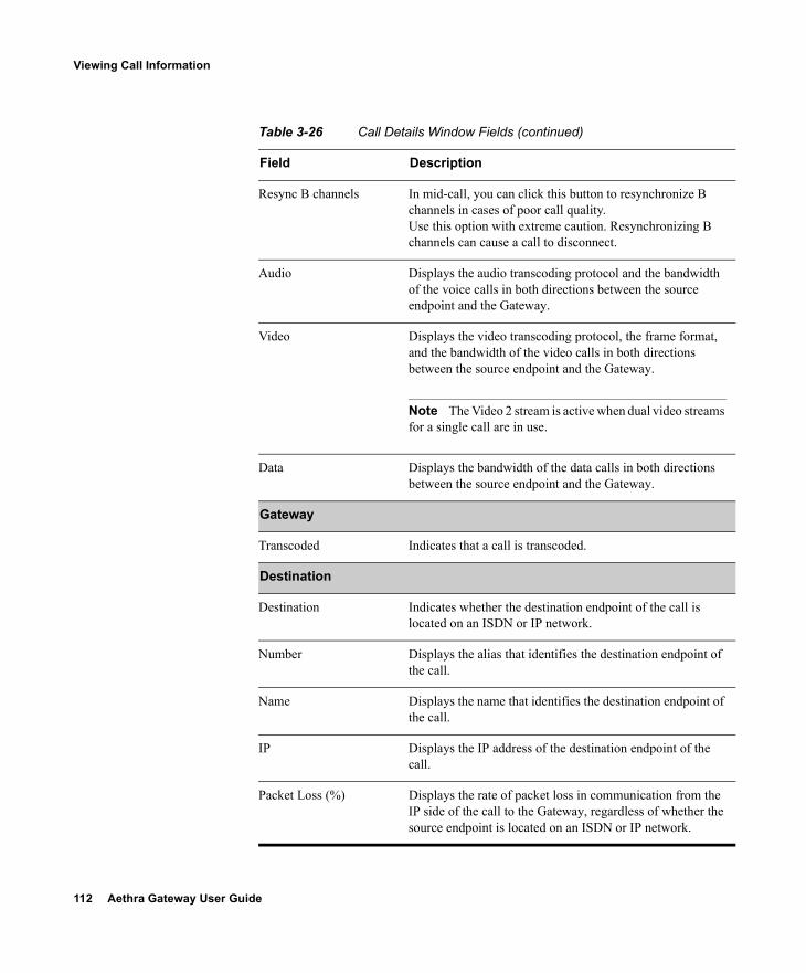
112 Aethra Gateway User Guide
Viewing Call Information
Resync B channels In mid-call, you can click this button to resynchronize B channels in cases of poor call quality.Use this option with extreme caution. Resynchronizing B channels can cause a call to disconnect.
Audio Displays the audio transcoding protocol and the bandwidth of the voice calls in both directions between the source endpoint and the Gateway.
Video Displays the video transcoding protocol, the frame format, and the bandwidth of the video calls in both directions between the source endpoint and the Gateway.
Note The Video 2 stream is active when dual video streams for a single call are in use.
Data Displays the bandwidth of the data calls in both directions between the source endpoint and the Gateway.
Gateway
Transcoded Indicates that a call is transcoded.
Destination
Destination Indicates whether the destination endpoint of the call is located on an ISDN or IP network.
Number Displays the alias that identifies the destination endpoint of the call.
Name Displays the name that identifies the destination endpoint of the call.
IP Displays the IP address of the destination endpoint of the call.
Packet Loss (%) Displays the rate of packet loss in communication from the IP side of the call to the Gateway, regardless of whether the source endpoint is located on an ISDN or IP network.
Table 3-26 Call Details Window Fields (continued)
Field Description
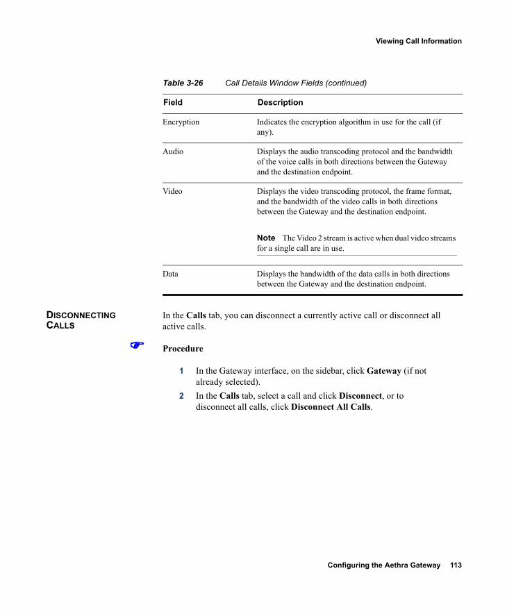
Configuring the Aethra Gateway 113
Viewing Call Information
DISCONNECTING CALLS
In the Calls tab, you can disconnect a currently active call or disconnect all active calls.
Procedure
1 In the Gateway interface, on the sidebar, click Gateway (if not already selected).
2 In the Calls tab, select a call and click Disconnect, or to disconnect all calls, click Disconnect All Calls.
Encryption Indicates the encryption algorithm in use for the call (if any).
Audio Displays the audio transcoding protocol and the bandwidth of the voice calls in both directions between the Gateway and the destination endpoint.
Video Displays the video transcoding protocol, the frame format, and the bandwidth of the video calls in both directions between the Gateway and the destination endpoint.
Note The Video 2 stream is active when dual video streams for a single call are in use.
Data Displays the bandwidth of the data calls in both directions between the Gateway and the destination endpoint.
Table 3-26 Call Details Window Fields (continued)
Field Description
114 Aethra Gateway User Guide
Viewing Gateway Alarm Events
VIEWING GATEWAY ALARM EVENTS
In the Event Log tab, you can view a list of reported alarm events. The Event Log tab displays the following information:
Event ID—Displays the identifier for the specified alarm event. Type—Displays the type of event. Time—Displays the time at which the reported event occurred. Severity—Displays the severity of the reported event. Message—Displays the error message used to report the event. Total—Displays the total number of reported alarm events. Clear All—Click to clear all events from the Event Log tab.
See Table 3-8 for a list of PRI gateway SNMP events. See Table 3-9 for a list of BRI Gateway SNMP events.
VIEWING GATEWAY STATISTICS
In the Statistics tab, you can view system-specific information such as call traces and debugging details. The Statistics tab displays the following:
Gateway start-up counter—Displays the number of times that the Gateway has reset.
Details button—Click to display the Details window, which lists the last three reasons for Gateway power failure.
ISDN LOF event counter (PRI gateways only)—Displays the total number of ISDN Loss of Frame (LoF) errors recorded on both Gateway PRI ports.
CRC error/event counter on ISDN (PRI gateways only)—Displays the total number of CRC errors on the ISDN network recorded on both Gateway PRI ports.
ICMP-in-message counter—Displays the number of Internet Control Message Protocol (ICMP) packets received.
UDP-in-datagram counter—Displays the number of User Datagram Protocol (UDP) packets received.
Packet loss counter—Displays the number of lost packets. Packet late counter—Displays the number of late packets. Accumulated time of B channel usage—Displays the total B
channel usage (in minutes). Counter reset time—Displays the last time at which the counters
were reset. Reset Counters button—Click to reset all counters to zero.
Configuring the Aethra Gateway 115
Configuring Gateway Maintenance Tasks
CONFIGURING GATEWAY MAINTENANCE TASKS
In the Maintenance tab, you can enter maintenance mode. In maintenance mode, you can perform maintenance work on the Gateway, such as upgrading software. In maintenance mode, the Gateway cannot accept new calls. You can disconnect all calls currently active in the Gateway, or wait for them to disconnect. In maintenance mode, you can only modify the following configuration settings:
Services (see About Gateway Services on page 86 for more information)
Fractional B channel status (PRI gateways only) (see Viewing B Channel Status on page 46 for more information)
Gatekeeper IP connectivity (see Configuring IP Connectivity Settings on page 48 for more information).
Resource allocation IVR (see Configuring IVR Settings on page 55 for more information)
To enter maintenance mode, click Enter Maintenance Mode. To exit maintenance mode, click Exit Maintenance Mode.
SAVING CONFIGURATION SETTINGS
You can save Gateway configuration settings to a file and then export this file to a storage device on your network. You can use the saved configuration file to restore the settings to the current Gateway unit or to configure a similar Gateway unit.An exported configuration file saves most of the current Device section settings and all of the current Gateway section settings.
Note You cannot save configuration settings in the System category.
You must use the Export button on the toolbar to save the configuration settings to a file. The Export button appears only when Gateway section settings are activated. When you save a configuration file, the current Device section settings are saved in the file. If you want to change these settings for export, click Upload on the toolbar to save these settings to configuration memory prior to saving the configuration file.
116 Aethra Gateway User Guide
Importing Configuration Files
Procedure
1 In the Gateway interface, on the sidebar, click Device.2 Make sure that the settings in the Basics, Addressing, Web
and Users tabs are correct.
Note Date parameters are not saved to the configuration file.
3 Click Upload to save these settings.4 On the sidebar, click Gateway.5 Make sure that the settings in the Status, Settings, PRI or
Serial Ports, Calls, Event Log and Statistics tabs are correct.6 Click Upload to save these settings.7 On the toolbar, click Export.
Note A dialog box appears indicating that you are navigating away from the page without saving the changes. Select the option to continue.
The File Download dialog box appears. 8 Save the configuration settings file to your chosen location.
The file extension .ini is automatically appended to the file name.
IMPORTING CONFIGURATION FILES
You can import the settings of a saved Gateway unit configuration file from a storage device on your network. You can use the saved configuration file to restore the settings to the current Gateway unit or to configure another Gateway unit.
Procedure
1 In the Gateway interface, on the sidebar, click Gateway.2 On the toolbar, click Import.
The Import a Configuration File page appears.
Configuring the Aethra Gateway 117
Importing Configuration Files
3 Click Browse.The Choose file dialog box appears.
4 Navigate to and select the configuration file you want to import.
Note The file must have an .ini extension.
5 Click Open.The file path appears in the File Name field.
6 Click Import.The file appears in the Gateway category window, and the Upload button is active.
Note You can open and change settings in any of the Gateway category options without losing the original settings in the configuration file. However, you must click Upload on the toolbar to retain these setting before selecting another category.
7 Click Upload to save the settings in configuration memory.
Note Uploading the file resets the device.

Using the Aethra Gateway 119
4USING THE AETHRA GATEWAY
This section provides sample scenarios for using the Aethra Gateway with configuration details and dialing examples, including the following:
About Dialing Out to the ISDN Network via the Gateway About Dialing In to the IP Network via the Gateway
ABOUT DIALING OUT TO THE ISDN NETWORK VIA THE GATEWAY
This section describes how to dial between IP and ISDN networks using the Gateway. When you dial out from an IP network to an ISDN network, you dial a service prefix followed by a string that usually includes the destination area code, the destination phone number and any required extra characters such as an asterisk (*), pound sign (#) or delimiter. The service prefix indicates that the call is to go through the Gateway, and also indicates the properties of the call such as the call type or bandwidth requirements.
ABOUT GATEWAY SERVICE PREFIXES
Gateway services define different call types and bandwidths for IP network endpoints. The services are identified by service prefixes. The network administrator in charge of the H.323 network is responsible for defining services and informing users of available services. See About Gateway Services on page 86 for more information.
Note A service prefix should not be the same as the first digits of an IP endpoint phone number.
120 Aethra Gateway User Guide
About Dialing Out to the ISDN Network via the Gateway
Dialing Example 1: Voice calls
The number string 912015294300 is a voice call from an IP network terminal to an H.323 endpoint on another IP network or to a terminal on the ISDN network. This number string consists of:
9—The service prefix for a voice call. 12015294300—The destination phone number including the area
code.
Dialing Example 2: Voice calls with the auto bit-rate setting service
The number string 712015294300 is a voice call from an IP network terminal to an H.323 endpoint on another IP network or to a terminal on the ISDN network using a service with the bit rate setting of auto. This number string consists of:
7—The auto bit-rate setting service prefix for a voice call. 12015294300—The destination phone number including the area
code.The bit rate of the call is fixed according to the setting in the source IP network terminal.
Dialing Example 3: 1B video calls
The number string 821816455318 is a 1B video call from an IP network terminal to an H.323 endpoint on another IP network or to a terminal on the ISDN network. This number string consists of:
82—The service prefix for a 1B video call. 1816455318—The destination phone number including the area
code.
ABOUT SECOND NUMBER DELIMITERS
To dial an outgoing 2B call, you dial the service prefix for 1B calls and the two B channel phone numbers. Because some H.323 endpoints do not support dialing long number strings or two phone numbers, you can use a delimiter to indicate to the Gateway the end of one number and the beginning of the other. See Configuring Outgoing Call Delimiters on page 56 for more information.
Dialing Example 4: 2B video calls
The number string 821816455318* is a 2B video call from an IP network terminal to an H.323 endpoint on another IP network or to a terminal on the ISDN network. Both B channels have the same number. This number string consists of:
Using the Aethra Gateway 121
About Dialing Out to the ISDN Network via the Gateway
82—The service prefix for a 2B video call. 1816455318—The destination phone number including the area
code. *—The second number delimiter. The second number delimiter tells
the Gateway to dial the destination phone number a second time.
Dialing Example 5: 2B video calls
The number string 821816455318*1816455319 is a 2B video call from an IP network terminal to an H.323 endpoint on another IP network or to a terminal on the ISDN network. The B channels have different numbers (or your endpoint does not have two phone number fields). This number string consists of:
82—The service prefix for a 2B video call. 1816455318—The destination phone number including the area
code. *—The second number delimiter. 1816455319—The second B channel number including the area
code.
Dialing Example 6: 6B bonded high quality video calls
The number string 867455001 is a 6B bonded high quality video call from an IP network terminal to an ISDN network terminal. This number string consists of:
86—The service prefix for 6B bonded calls. 7455001—The phone number of the destination terminal.
Dialing Example 7: IP-ISDN-IP direct dialing—Gateway supports TCS4
The number string 9825645000^3333 is a call from an IP network endpoint (Endpoint 1) to an IP network endpoint in another zone (Endpoint 2), through a public ISDN network, as shown in Figure 4-1. Gateway A dials using TCS4, while Gateway B is set to receive calls in TCS4 mode.

122 Aethra Gateway User Guide
About Dialing In to the IP Network via the Gateway
Figure 4-1 TCS4 Dialing
This number string consists of: 9—The voice call service prefix in Gateway A in Zone A. 82—The service prefix for a 2B video call in Gateway A in Zone A. 5645000—The number of the destination Gateway B on the public
ISDN network. ^—The TCS4 delimiter configured in Gateway A. 3333—The E.164 number of the destination IP Endpoint 2.
ABOUT DIALING IN TO THE IP NETWORK VIA THE GATEWAY
The Gateway is responsible for routing incoming calls to the requested H.323 endpoints on the IP network.When a terminal or phone on the ISDN network wants to reach an IP endpoint, it has to dial at least one of the phone numbers assigned to the ISDN line connected to the Gateway PRI or BRI ISDN port.
ABOUT INCOMING CALL ROUTING
When a call originating on the ISDN network reaches the Gateway, the Gateway routes it to an IP network endpoint. This is achieved through one of several incoming call routing methods that the Gateway supports. You can enable any number of routing methods for each port, but at least one method must be enabled for incoming calls to be routed through that port. The Gateway routes an incoming call from the ISDN network according to the routing methods enabled for the ISDN port, following this order of priority: DID −>TCS4 −>IVR−>Default Extension.If a routing method fails, the Gateway automatically tries to route the call through the next routing method in line. If all methods fail, the call is rejected. The call might also be rejected if the Gateway routes the call to an endpoint that is busy or not available.Table 4-1 explains the routing methods.
PublicISDN
IP
Gateway A Gateway B5645000
IP
Endpoint 1 Endpoint 23333
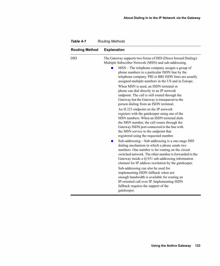
Using the Aethra Gateway 123
About Dialing In to the IP Network via the Gateway
Table 4-1 Routing Methods
Routing Method Explanation
DID The Gateway supports two forms of DID (Direct Inward Dialing): Multiple Subscriber Network (MSN) and sub-addressing.
MSN—The telephone company assigns a group of phone numbers to a particular ISDN line by the telephone company. PRI or BRI ISDN lines are usually assigned multiple numbers in the US and in Europe.When MSN is used, an ISDN terminal or phone can dial directly to an IP network endpoint. The call is still routed through the Gateway but the Gateway is transparent to the person dialing from an ISDN terminal. An H.323 endpoint on the IP network registers with the gatekeeper using one of the MSN numbers. When an ISDN terminal dials the MSN number, the call routes through the Gateway ISDN port connected to the line with the MSN service to the endpoint that registered using the requested number.
Sub-addressing—Sub-addressing is a one-stage DID dialing mechanism in which a phone sends two numbers. One number is for routing on the circuit switched network. The other number is forwarded to the Gateway inside a Q.931 sub-addressing information element for IP address resolution by the gatekeeper.Sub-addressing can also be used for implementing ISDN fallback when not enough bandwidth is available for routing an IP-oriented call over IP. Implementing ISDN fallback requires the support of the gatekeeper.
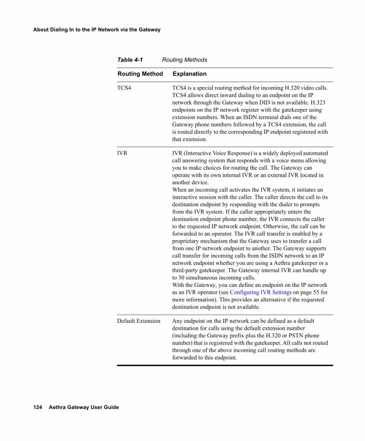
124 Aethra Gateway User Guide
About Dialing In to the IP Network via the Gateway
TCS4 TCS4 is a special routing method for incoming H.320 video calls. TCS4 allows direct inward dialing to an endpoint on the IP network through the Gateway when DID is not available. H.323 endpoints on the IP network register with the gatekeeper using extension numbers. When an ISDN terminal dials one of the Gateway phone numbers followed by a TCS4 extension, the call is routed directly to the corresponding IP endpoint registered with that extension.
IVR IVR (Interactive Voice Response) is a widely deployed automated call answering system that responds with a voice menu allowing you to make choices for routing the call. The Gateway can operate with its own internal IVR or an external IVR located in another device.When an incoming call activates the IVR system, it initiates an interactive session with the caller. The caller directs the call to its destination endpoint by responding with the dialer to prompts from the IVR system. If the caller appropriately enters the destination endpoint phone number, the IVR connects the caller to the requested IP network endpoint. Otherwise, the call can be forwarded to an operator. The IVR call transfer is enabled by a proprietary mechanism that the Gateway uses to transfer a call from one IP network endpoint to another. The Gateway supports call transfer for incoming calls from the ISDN network to an IP network endpoint whether you are using a Aethra gatekeeper or a third-party gatekeeper. The Gateway internal IVR can handle up to 30 simultaneous incoming calls.With the Gateway, you can define an endpoint on the IP network as an IVR operator (see Configuring IVR Settings on page 55 for more information). This provides an alternative if the requested destination endpoint is not available.
Default Extension Any endpoint on the IP network can be defined as a default destination for calls using the default extension number (including the Gateway prefix plus the H.320 or PSTN phone number) that is registered with the gatekeeper. All calls not routed through one of the above incoming call routing methods are forwarded to this endpoint.
Table 4-1 Routing Methods
Routing Method Explanation
Using the Aethra Gateway 125
About Dialing In to the IP Network via the Gateway
ABOUT THE IVR OPERATOR
You can define an IP network endpoint as an IVR operator and configure the Gateway ports accordingly. See Configuring IVR Settings on page 55 for more information.
Dialing Example 8: Direct dialing to an IP network endpoint (Gateway supports DID)
The number string 5645001 is a call from an ISDN network terminal to an IP network endpoint. This number string consists of:
5645001—The destination endpoint phone number. The call is routed to the requested endpoint according to its registration identity in the gatekeeper.
Dialing Example 9: Direct dialing to an IP network endpoint (Gateway supports TCS4 but not DID)
The number string 5645000^5776 is a call from an ISDN terminal to an IP network endpoint. The dialing endpoint must also support TCS4. This number string consists of:
5645000—The Gateway phone number. ^—The TCS4 delimiter of the dialing endpoint (if required). 5776—The extension number of the requested endpoint.
Note TCS4 only routes H.320 video calls.
ABOUT DIALING THROUGH THE IVR
When the Gateway does not support DID or TCS4, you can reach an endpoint using the Interactive Voice Response (IVR) routing mechanism. When IVR is enabled, you are answered by a recorded message prompting you to enter the destination endpoint phone number followed by the pound (#) sign. If you enter the number of an endpoint that is online and currently not busy, the IVR connects the call to the requested endpoint.
Dialing Example 10: Dialing to an IP network endpoint through the IVR
The number string 5645000 <wait for the IVR to respond> 5561# is a call through an IVR routing mechanism. This number string consists of:
5645000—The Gateway phone number. 5561—The number of the requested endpoint. #—This is required by the IVR for call completion.
126 Aethra Gateway User Guide
About Dialing In to the IP Network via the Gateway
ABOUT DIALING INDIRECTLY THROUGH AN OPERATOR
If you do not dial the number of a destination endpoint when requested to do so by the IVR, the IVR automatically passes you to an operator. You can define any endpoint on the IP network as the IVR operator (see Configuring IVR Settings on page 55 for more information).When IVR is enabled, you are answered by a recorded message prompting you to enter the destination endpoint phone number. If you do not know the destination endpoint number, the IVR routes the call from the Gateway using ISDN to the IP network endpoint that is defined as the IVR operator.
Dialing Example 11: Dialing to an IP network endpoint through an operator
The number string 5645000 <wait for the IVR to respond>* is a call to an IP network through an IVR operator. This number string consists of:
5645000—The Gateway phone number. *—This character is optional.
Troubleshooting the Aethra Gateway 127
5TROUBLESHOOTING THE AETHRA GATEWAY
This section covers problems you might encounter when configuring, operating and managing the Aethra Gateway. This chapter provides suggested actions you can use to solve the problems, and includes the following topics.This chapter discusses the following topics:
About Problems Encountered Setting the IP Address About LED Indications About Problems with Outbound Calls About Problems with Inbound Calls Monitoring from a Remote Site Using the Hyperterminal Configuration Commands
ABOUT PROBLEMS ENCOUNTERED SETTING THE IP ADDRESS
This section identifies problems that you can have assigning an IP address to a new Gateway, and suggests possible solutions.
Symptom Cannot access the Gateway through the serial port. Information from the Gateway does not appear on the terminal
emulator screen.
128 Aethra Gateway User Guide
About Problems Encountered Setting the IP Address
Recommended Action Make sure that the terminal emulator modem is set using the
parameters as follows: Baud rate: 9600 Data bits: 8 Parity: None Stop bits: 1 Flow control: None
Make sure that the terminal cable that is shipped with the unit or a null cable is securely connected to the Gateway serial port and to the computer serial port.
Verify that the Gateway can communicate with the terminal by using the procedure below.
Procedure
1 Launch the terminal emulation software installed on the computer you have connected to the Gateway serial port.A prompt appears.
2 Press Enter. If the prompt moves, the terminal emulator is communicating with the Gateway.
3 Restart the Gateway. A log of the start up events appears on the computer monitor. If nothing appears, check the cable connection between the Gateway and the computer. You must use the terminal cable that is shipped with the unit or a null cable. If the problem persists, contact Aethra Technical Support for assistance.
Troubleshooting the Aethra Gateway 129
About LED Indications
SymptomThe terminal emulator does not display the configuration menu.
Possible CauseAfter the power to the Gateway is turned on, the terminal emulator connection displays a countdown. Pressing any key causes the Gateway to begin initialization and you see the “Main application started. Please wait ...” message. When initialization is complete the “Press any Key To start configuration ...” prompt should display.
Recommended ActionTo reset the Gateway, press the RST button on the Gateway front panel.
ABOUT LED INDICATIONS
This section identifies problems that the LEDs can indicate, and suggests possible solutions.
Symptom The 10/100BaseT link LED does not light up.The 10/100BaseT link LED is embedded in the 10/100BaseT jack on your left as you face the Gateway front panel. When this LED is lit, it indicates that the Gateway is connected to the network.
Recommended Action Make sure that the LAN cable is connected to the 10/100BaseT-1 jack
on the front panel of the Gateway. Make sure that the devices at both ends of the link are powered-up. Make sure that you use a RJ-45 jack with standard wiring to connect
the LAN cable to the Gateway 10/100BaseT-1 jack. Reset the Gateway by pressing the RST button on the front panel or
by clicking Reset in the toolbar of the Administrator interface. After the Gateway restarts, check the link LED.
130 Aethra Gateway User Guide
About LED Indications
Perform a ping test from a PC terminal to the Gateway IP address. If the Gateway is connected to the network, the ping returns the message “Reply from …”. If the Gateway does not respond to the ping, the ping returns the message “Request timeout.”If you receive a “Request timeout” message, try replacing the cable and repeat the ping test. Also, make sure that you properly configure the Gateway IP address and subnet mask, and the router IP address.
Symptom Why doesn’t the GK LED light up?
Possible Cause The GK LED indicates that the Gateway has an active registration with the gatekeeper.
Recommended Action Make sure that you specify the gatekeeper with which you want the
Gateway to register in the Gateway Administrator interface. Make sure that the IP address of the gatekeeper the Gateway is to
register with is correct. Make sure that the gatekeeper is working.
Symptom Why is the ALRM LED on?
Possible Cause The ALRM LEDs light up when there is a data transmission error during a call. Errors that trigger the alarm include loss of signal, loss of frame, excessive errors and incorrect configuration.The Gateway has an ALRM LED on the front panel and an alarm for each port on the rear panel. The ALRM LED on the front panel indicates that there is a line error. The ALRM LEDs on the rear panel are associated with an ISDN or serial line and indicate whether the error is from the LAN endpoint (local) or Public Switched Telephone Network (PSTN) endpoint (remote).
Recommended Action Make sure you use the correct cable. Make sure that the LAN cable is connected.
Troubleshooting the Aethra Gateway 131
About Problems with Outbound Calls
Make sure that the Gateway port configuration is compatible with how the ISDN line is configured.
If the Gateway is connected to a PBX, make sure that the PBX is properly connected and configured.
If the Gateway is connected directly to a central office switch, make sure that the BRI service is provisioned to support the Gateway (for BRI Gateways) or that the PSTN line is configured to support the Gateway (for PRI gateways).
ABOUT PROBLEMS WITH OUTBOUND CALLS
This section identifies problems that users can have making calls through the Gateway and suggests possible solutions.
Symptom Why are end users unable to make outbound calls?
Possible Cause Data is not being transported to the call participants.
Recommended Action Make sure that the call initiator is using a valid Gateway service
prefix to dial the call. Make sure that the call initiator is using the correct service for the
call. (If the call is a voice call, the service should be configured for voice-only.)
Make sure that the call initiator is correctly dialing the number. Make sure that the dialing endpoint is registered with a gatekeeper. For long distance calls, make sure that the BRI or PRI service is
configured to support long distance calls. Make sure that the service is registered with the gatekeeper.
Possible Cause The BRI or PRI line might have been connected to the Gateway in the wrong order.
Recommended Action Make sure that the PRI or BRI lines are connected before the
Gateway is turned on. If the Gateway is turned on before the lines are connected, the service is not available.
132 Aethra Gateway User Guide
About Problems with Inbound Calls
Make sure that the terminal cable is properly connected to the Gateway. When working with an IMUX, make sure that the IMUX is properly configured.
Reset the Gateway to activate the service.
ABOUT PROBLEMS WITH INBOUND CALLS
This section identifies problems users can have receiving calls through the Gateway, and suggests possible solutions.
Symptom Why are end users unable to receive incoming calls?
Possible Cause The Gateway might not be configured correctly.
Recommended Action Make sure that at least one routing method is defined for each active
PRI or BRI port. See Configuring Port Call Policies on page 108 for information about configuring routing for incoming calls.
Make sure that parameters for Interactive Voice Response (IVR) or the default extension is set to provide assistance for incoming calls that cannot be directly routed. See Configuring Port Call Policies on page 108 for information about configuring routing for incoming calls.
Make sure that the endpoint on the LAN that is designated to process incoming calls that require assistance is registered with the gatekeeper and the Gateway.
Make sure that the PRI or BRI numbers are properly configured in the Gateway.

Troubleshooting the Aethra Gateway 133
About Problems with Inbound Calls
Symptom Why are direct-dial calls not reaching the intended endpoint and why is the IVR not invoked?
Possible Cause The endpoint of the call recipient might not be registered with a gatekeeper or the telephone line is not working properly.
Recommended Action For PRI or BRI ports, make sure that the DID number is associated
with an endpoint registered with a gatekeeper and that the number is included in the registration profile of the endpoint. Incoming calls the Gateway receives for unused BRI or PRI phone numbers are disconnected.
Make sure that the BRI or PRI line is in working order. Disconnect the BRI or PRI line from the Gateway and connect it to a
regular PSTN phone. Dial the number. If the phone does not ring, the DID line is out of order.
Possible Cause There is a mismatch between the number of digits in the dial number that the service provider sends in DID calls and the number of digits in the corresponding E.164 addresses registered with the gatekeeper.
Recommended Action Make sure that the service provider is sending the same number of digits in calls as specified for the DID service.Make sure that the service provider is sending the same number of digits in calls as specified for the DID service.For example, if the service specifies four significant digits in the number, the service provider must send four-digit numbers. If the service specifies seven significant digits in the number, the service provider must sends seven-digit numbers.
134 Aethra Gateway User Guide
About Problems with Inbound Calls
Symptom When TCS4 is used, why do TCS4 calls not reach the requested terminal?
Possible Cause The TCS4 number might not be registered with the gatekeeper or the Gateway is improperly configured.
Recommended Action Make sure that theTCS4 number is associated with an endpoint in the
gatekeeper registration table. Make sure that the TCS4 option is enabled for the PRI or BRI port.
See Configuring Port Call Policies on page 108 for information about configuring routing for incoming calls.
Symptom Why is the IVR not responding to incoming calls?
Possible Cause Endpoints placing calls to the Gateway must support DTMF to use the internal IVR. If the dialing endpoint does not support Dual Tone Multi-Frequency (DTMF) tones, the IVR forwards the call to the IVR operator or default extension operator if one is defined (see Configuring Port Call Policies on page 108 for more information).When the volume of the DTMF tones generated by the dialing endpoint is low, the IVR might not recognize one or more of the tones. If the Gateway does not find an endpoint with a phone number corresponding to the tones dialed, the IVR treats this string as an incorrect number and disconnects the call.
Recommended Action Make sure that the parameter that allows the Gateway to accept
DTMF for incoming calls is enabled. See Configuring IVR Settings on page 55 for information about how to set the IVR parameter.
Make sure that the dialing terminal supports DTMF tones. Make sure that the DTMF tones generated are loud enough. Make sure that the IVR operator number is associated with the
endpoint that is registered with the gatekeeper.
Troubleshooting the Aethra Gateway 135
Monitoring from a Remote Site
MONITORING FROM A REMOTE SITE
You can use the Gateway interface to monitor Gateway functions from a remote site. The LEDs on the Gateway front and rear panels are replicated in the LED Monitoring section of the Gateway Device interface. You can access this page from any computer on the LAN and monitor the module for connectivity or communication problems.
Procedure
1 Launch a Java-based web browser.2 In the address or URL field, enter the IP address of the
Gateway that you want to monitor.The Gateway interface appears.
3 In the User Name field, enter a valid user name.4 In the Password field, enter the user password.
The Gateway Settings page appears.5 On the sidebar, click Device.6 Click the LED Monitoring tab (if not already selected).
The LED Monitoring tab appears.
USING THE HYPERTERMINAL CONFIGURATION COMMANDS
This section describes configuration commands that you can access through the Gateway serial port. You can use some of these commands to set device parameters that are unavailable in the Gateway interface. This section describes how to use the hyperterminal do the following:
Accessing Device Commands through the Serial Port on page 135 Changing a Global User Name and Password on page 137 Setting Echo Cancellation on page 137 Configuring the Web Server Port on page 138 Setting T.120 Data Collaboration Capability on page 138 Restoring the Factory Default Settings on page 139 Configuring the Ethernet Port on page 139
ACCESSING DEVICE COMMANDS THROUGH THE SERIAL PORT
You can access device commands through the Gateway serial port. You can use these commands to configure networking information, set factory defaults, or configure Ethernet port settings.
136 Aethra Gateway User Guide
Using the Hyperterminal Configuration Commands
Procedure
1 Connect the appropriate ends of the terminal cable to the serial port on the computer and the serial port on the Gateway.
Note The terminal cable is a null cable that is shipped with the Gateway module.
2 Launch the terminal emulator on the computer.3 Set the communication values for the terminal emulator as
follows: Baud rate: 9600 Data bits: 8 Parity: None Stop bits: 1 Flow control: None
4 After the terminal emulator session starts, press the RST button on the Gateway front panel, or click the Reset button on the toolbar of the LED Monitoring tab of the Gateway Device interface.A log of the auto-boot events appears.
5 When the message “Press any key to start configuration” appears on the screen, press any key within 6 seconds. The following command line options appear. Enter <N> to configure default network port values Enter <P> to change the configuration software
password Enter <A> to display advanced configuration menu Enter <Q> to quit configuration menu and start the
Gateway6 Select an option to execute.
Troubleshooting the Aethra Gateway 137
Using the Hyperterminal Configuration Commands
CHANGING A GLOBAL USER NAME AND PASSWORD
Several applications use the same global user name and password to log in to the Gateway. These applications include the Upgrade Utility that allows you to change the Gateway software, the Upload Utility that allows you to change the IVR messages, and the Telnet utility that allows you to monitor the Gateway operations. This user name and password are also used to log in to the Gateway interface. A newly-added administrator automatically has access to these utilities.
Procedure
1 At the prompt for the command line options, press P to change the software password and then press Enter.
2 At the Enter user name prompt, enter the name that you want to use and then press Enter. The user name is case sensitive.
3 At the Enter new password prompt, enter the password that you want to use and then press Enter. The password is case sensitive.A message appears verifying that the password is changed and the command line options appear.
4 Enter Q to continue the Gateway module boot cycle and then press Enter.
SETTING ECHO CANCELLATION
You can use these advanced commands to set echo cancellation for the Gateway. To set echo cancellation, perform the following steps:
Procedure
1 At the prompt for the command line options, press A to display the advanced command menu.
2 Press 1 to enable or disable echo cancellation for voice-only calls and then press Enter.
3 At the “0/1-disable/enable echo cancellation (voice calls)” prompt, do one of the following: Press 0 to disable echo cancellation. Press 1 to enable echo cancellation.
4 Press Enter.
138 Aethra Gateway User Guide
Using the Hyperterminal Configuration Commands
CONFIGURING THE WEB SERVER PORT
You can set the port number that the Gateway uses for posting its web pages. The default value is 80, which is the standard for web server ports. If another port is used in your environment, you can use this command to change the Gateway module web server port setting.
Procedure
1 At the prompt for the command line options, press A to display the advanced command menu.
2 Press 2 and then press Enter to configure the web server port.3 At the Enter a new port number for the web server prompt,
enter the value that you want to use and then press Enter.
SETTING T.120 DATA COLLABORATION CAPABILITY
From the command line, you can use advanced commands to set the T.120 data collaboration capability for the Gateway.
Procedure
1 At the prompt for the command line options, press A to display the advanced command menu.
2 Press 4 to enable or disable echo cancellation for voice-only calls and then press Enter.
3 At the 0/1-disable/enable echo cancellation (voice calls) prompt, do one of the following: Press 0 to disable T.120. Press 1 to enable T.120.
4 Press Enter.
Troubleshooting the Aethra Gateway 139
Using the Hyperterminal Configuration Commands
RESTORING THE FACTORY DEFAULT SETTINGS
You can restore the factory default settings to the Gateway from the command line.
Procedure
1 At the prompt for the command line options, press A to display the advanced command menu.
2 Press 5 to restore the factory defaults.3 At the Are you sure you want to restore factory configuration?
[y, n] prompt, enter y and then press Enter.
CONFIGURING THE ETHERNET PORT
You can use the command line commands to configure the speed of the Gateway Ethernet port.
Procedure
1 At the prompt for the command line options, press A to display the advanced command menu.
2 Press 6 to change the network working mode.A list of Ethernet configuration options appear.
3 At the Choose working mode prompt, select one of the following: Press 1 to configure the Gateway for half-duplex
operation. Press 2 to configure the Gateway for full-duplex
operation. Press 3 to configure the Gateway to negotiate the
working mode with the router or switch. This is the default setting.
Press any other key to return to the main menu without making changes.
4 Press Enter.5 At the Choose Speed working mode prompt, select one of the
following: Press 1 to configure the Gateway to support 100 Mbps
Ethernet speed.
140 Aethra Gateway User Guide
Using the Hyperterminal Configuration Commands
Press 2 to configure the Gateway to support 10 Mbps Ethernet speed.
Press 3 to allow the Gateway module to negotiate the Ethernet speed with the router or switch. This is the default setting.
Press any other key to return to the configuration menu without changing the setting.
6 Press Enter.
Using the Aethra Audio Message Utility 141
6USING THE AETHRA AUDIO MESSAGE UTILITY
This section describes the Aethra Audio Message Utility, and includes the following topics:
Introduction About Gateway Call Routing Launching the Utility Playing a Message Recording a Message Replacing a Message Uploading a Message to a Device Viewing Message Details Exiting the Utility About Express Setup Using Express Setup
142 Aethra Gateway User Guide
Introduction
INTRODUCTION The Aethra Audio Message Utility is an interactive GUI that enables you to record and replace messages and upload new messages to the call routing mechanisms in Aethra devices. Each Aethra device has a built-in set of audio messages. The default messages are in English. The Aethra Audio Message Utility allows you to record new messages in a different language or with different content to suit your requirements. The Aethra Audio Message Utility also enables you to replace and upload new messages to the target Aethra device.There are two ways of using the Aethra Audio Message Utility. The standard utility functions enable you to play, record or replace messages. The Express Setup guides you through the recording, replacing and upload procedure for each of the voice messages.
Before You Begin
Before you can record, play and upload messages to the target Aethra device, you must
Save recorded messages as WAV files. Know the IP address of the target device.
ABOUT GATEWAY CALL ROUTING
The Aethra Audio Message Utility provides audio messages for the call routing mechanism in Aethra Gateways. The call routing mechanism initiates a series of voice messages that allow you to make choices and respond via the keypad through dial tones (DTMF). The routing mechanism enables you to dial through the Aethra Gateway to an IP network-based H.323/SIP/RTSP terminal when you do not know the extension number of the destination terminal.
LAUNCHING THE UTILITY
This section describes how to install and launch the Aethra Audio Message Utility.
Procedure
1 Download the Setup.exe file from the distribution CD.2 Launch the utility from the Start menu by selecting Programs
and clicking Audio Message Utility.
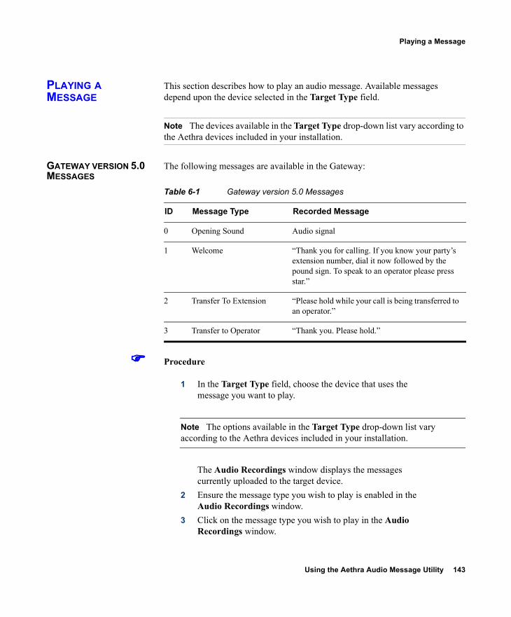
Using the Aethra Audio Message Utility 143
Playing a Message
PLAYING A MESSAGE
This section describes how to play an audio message. Available messages depend upon the device selected in the Target Type field.
Note The devices available in the Target Type drop-down list vary according to the Aethra devices included in your installation.
GATEWAY VERSION 5.0 MESSAGES
The following messages are available in the Gateway:
Procedure
1 In the Target Type field, choose the device that uses the message you want to play.
Note The options available in the Target Type drop-down list vary according to the Aethra devices included in your installation.
The Audio Recordings window displays the messages currently uploaded to the target device.
2 Ensure the message type you wish to play is enabled in the Audio Recordings window.
3 Click on the message type you wish to play in the Audio Recordings window.
Table 6-1 Gateway version 5.0 Messages
ID Message Type Recorded Message
0 Opening Sound Audio signal
1 Welcome “Thank you for calling. If you know your party’s extension number, dial it now followed by the pound sign. To speak to an operator please press star.”
2 Transfer To Extension “Please hold while your call is being transferred to an operator.”
3 Transfer to Operator “Thank you. Please hold.”
144 Aethra Gateway User Guide
Recording a Message
4 From the Message menu, select Play Message.The Play Recording dialog box appears. You can stop or replay the message you have selected to play.
RECORDING A MESSAGE
This section describes how to record a new audio message.
Procedure
1 From the Message menu, select New Recording.The New Recording confirmation box appears and the MSsound recording utility is invoked.
Note MSsound is invoked by default. You can use any recording software that supports the WAV format.
The new message must be recorded in the following formats: WAV file G.711 (CCITT) µ-Law 8-bit Sampling rate 8kHz
2 Use the recording software, to record a new message and save it to the Aethra Audio Message Utility directory.
Using the Aethra Audio Message Utility 145
Replacing a Message
REPLACING A MESSAGE
This section describes how to replace an audio message.
Procedure
1 In the Target Type field, choose the device that uses the message you want to replace.
Note The options available in the Target Type drop-down list vary according to the Aethra devices included in your installation.
2 The Audio Recordings window displays the messages currently uploaded to the target device. Click the message type in the Audio Recordings window you wish to replace.
3 From the Message menu, select Properties.The Properties dialog box appears showing the name of the message you selected in the Message Type field.
4 (Optional) Enter the text that you want to appear in the Message Type field in the Audio Recordings window.
5 Click the Browse button to choose the new message you wish to use.The Replace Recording dialog box appears.
6 Select the file with which you wish to replace the current message and click Open to confirm your selection.
7 Click OK in the Properties dialog box.8 The new message appears in the Audio Recordings window.
146 Aethra Gateway User Guide
Uploading a Message to a Device
UPLOADING A MESSAGE TO A DEVICE
This section describes how to upload audio messages from the Audio Message Utility to a target device.
Procedure
1 From the Actions menu, select Upload Messages To Target.The Upload dialog box appears.
2 In the General Information section, enter the IP address of the target device.
3 In the Login Information section, enter the user name and password of the target device, as configured in the device network configuration settings.
4 (Optional) Modify the read and write community settings for the target device as follows: Click the Customize SNMP Settings button.
The Customize SNMP Settings dialog box displays. Enter the required read community and write
community values and click OK.5 Click the Upload Messages button.
The Upload in progress window appears, and the message files are uploaded and burned onto the target device.
Using the Aethra Audio Message Utility 147
Viewing Message Details
VIEWING MESSAGE DETAILS
You can view the file name and length of the audio messages listed in the Audio Recordings window.
Procedure
1 Click the Target Type drop-down list.2 Choose the device that uses the message you want to replace.
Note The options available in the Target Type drop-down list vary according to the Aethra devices included in your installation.
The names of audio message files currently uploaded to the target device appear in the Recorded Message field of the Audio Recordings window.The lengths of audio message files currently uploaded to the target device appear in the Message Length (sec) field of the Audio Recordings window.
EXITING THE UTILITY
This section describes how to exit the Audio Message Utility.
Procedure
1 Open the Actions menu.2 Select Exit.
ABOUT EXPRESS SETUP
The Express Setup is an alternative way of recording, replacing and uploading messages. The Express Setup guides you through the recording, replacing and uploading procedure for each audio message.You proceed through the Express Setup sequentially for each message type. You are alternately prompted to select to record a new message and to navigate a path to a new message file with which you wish to replace a current file.
148 Aethra Gateway User Guide
Using Express Setup
As you proceed through the Express Setup, the dialog box displays the name the current message type and the associated message file.
Note You can skip the recording and replacing sequence for each message by clicking Next at each step in the Express Setup. You can return to any step in the procedure to change the setup for a particular message by clicking Back.
USING EXPRESS SETUP
This section describes how to use the Express Setup.
Procedure
1 Click Express Setup in the Tools menu. The Express Setup dialog box is displayed informing you of the name of the first message file in the selection and provides a check box for indicating whether you wish to create a new recording for the message.
2 Check the Create a new recording check box and click Next. The Express Setup dialog box displays the required format settings for the new message and the MSsound recorder is displayed. Use the MSsound recorder or other recording software to record the new message and save it to the Audio Message Utility directory.
3 When you have finished recording a new message, click Next. The Express Setup dialog box displays the path of the current file for the specified message type and the Replace button.
4 Click Replace. The Replace Recording window appears showing the directory containing the current sound files for the device.
5 Select the required file and click Open to replace this file with the current message file for the specified message.When you have completed the recording and replacement procedure, the Express Setup dialog box displays the new list of message types and message files associated with each type.
6 Click Upload. The Upload dialog box appears.
Using the Aethra Audio Message Utility 149
Using Express Setup
7 Type the IP address of the target device.8 Type the user name and password as defined in the network
configuration settings of the Aethra device. 9 Click the Upload Messages button to complete the upload
procedure.The Upload in progress window displays. The message files are uploaded and burned onto the target device.

Using the Aethra Software Upgrade Utility 151
7USING THE AETHRA SOFTWARE UPGRADE UTILITY
This section describes the Aethra Software Upgrade Utility, and includes the following topics:
Introduction Launching the Utility Upgrading Device Software
INTRODUCTION The Aethra Software Upgrade Utility is an interactive GUI interface that enables you to upgrade Aethra software installed on Aethra devices.The Aethra Software Upgrade Utility enables you to select files to be uploaded via a network or modem connection to the Aethra device. You can select either to perform a typical upgrade which includes all the new files or a customized upgrade which enables you to select which files to upload.The upgrade files are uploaded and then burned into the memory of the Aethra device.
Before You Begin
Aethra devices automatically save configuration settings before a software upgrade takes place. However, it is recommended that you save all configuration information using the Export button in the Aethra device web interface toolbar. You can retrieve all these settings after the software upgrade is complete by using the Import button in the Aethra device web interface toolbar.
152 Aethra Gateway User Guide
Launching the Utility
LAUNCHING THE UTILITY
This section describes how to install and launch the Aethra Software Upgrade Utility.
Procedure
1 From the network, locate the self-extracting executable file.2 Double click the self-extracting executable file to run the
Software Upgrade Utility.The upgrade files are extracted and the Upgrade Utility dialog box appears.
UPGRADING DEVICE SOFTWARE
This section describes how to use the Software Upgrade Utility to upgrade Aethra software installed on Aethra devices.
Procedure
1 In the General Information section of the Upgrade Utility dialog box, enter the IP address of the device you want to upgrade.
2 In the Login Information section, enter the administrator user name and password for the target device, as configured in the device network configuration settings.
3 (Optional) Modify the read and write community settings for the target device as follows: Click the Customize SNMP Settings button.
The Customize SNMP Settings dialog box displays. Enter the required read community and write
community values.
Note We recommend that you modify the default settings for security purposes.
Click OK to return to the Upgrade Utility dialog box.4 (Optional) Select the components of the target device you want
to upgrade as follows:
Using the Aethra Software Upgrade Utility 153
Upgrading Device Software
Click the Customize button.The Customize dialog box appears.
Check the device components you want to upgrade in the Select the components you want to upgrade list.
Note The components displayed vary according to the Aethra device upgraded.
Click OK to return to the Upgrade Utility dialog box.5 Click the Upgrade button to upgrade all components of the
Aethra device software (or only those components you manually selected via the Customize option).The Aethra Software Upgrade Utility informs you whether or not the upgrade is successful.
Note When the upgrade is complete, the Aethra device automatically resets itself and starts operation with the new software version.

Cable Connections and Pin-outs 155
8CABLE CONNECTIONS AND PIN-OUTS
This section describes the pin-to-pin and pin-out configurations of the connectors and cables of the Aethra Gateway unit, including the following topics:
Unit RS-232 9-Pin Serial Port RJ-45 8-Pin IP Network Port RJ-45 Serial Port Adapter Cable ISDN Port

156 Aethra Gateway User Guide
Unit RS-232 9-Pin Serial Port
UNIT RS-232 9-PIN SERIAL PORT
Table 8-1 describes the Aethra Gateway unit RS-232 9-pin D-type serial port pin-out configuration.
Table 8-1 RS-232 9-pin D-Type Serial Port Pin-out
Pin Function I/O1 NC
2 RXD Input
3 TXD Output
4 NC
5 GND
6 NC
7 NC
8 NC
9 NC
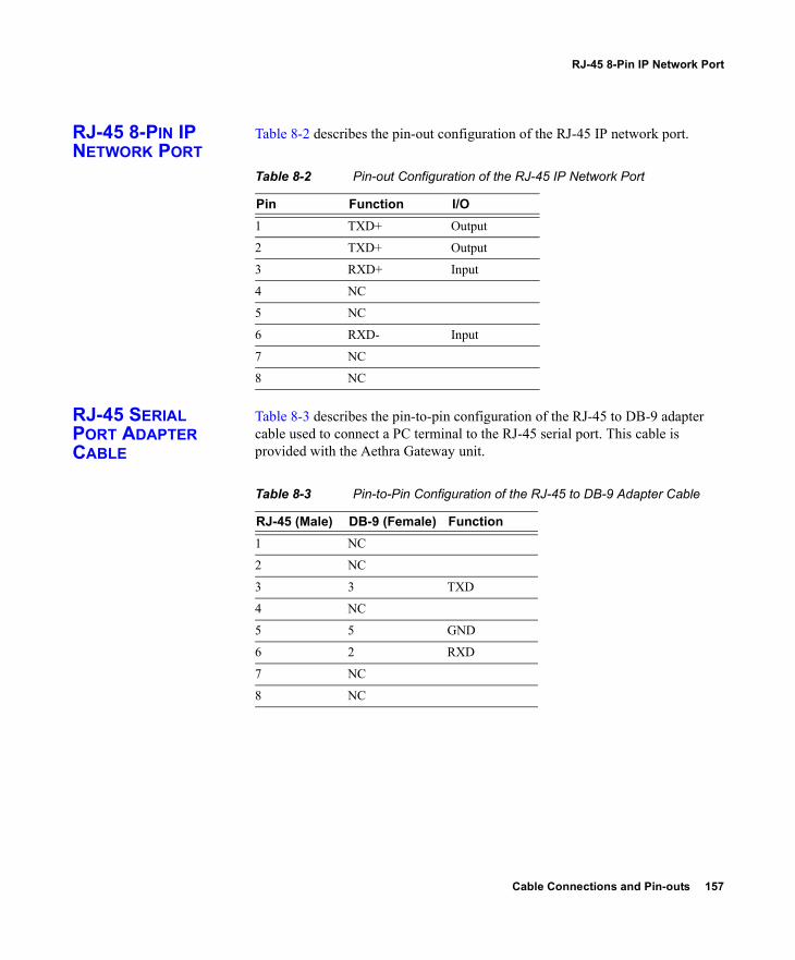
Cable Connections and Pin-outs 157
RJ-45 8-Pin IP Network Port
RJ-45 8-PIN IP NETWORK PORT
Table 8-2 describes the pin-out configuration of the RJ-45 IP network port.
Table 8-2 Pin-out Configuration of the RJ-45 IP Network Port
RJ-45 SERIAL PORT ADAPTER CABLE
Table 8-3 describes the pin-to-pin configuration of the RJ-45 to DB-9 adapter cable used to connect a PC terminal to the RJ-45 serial port. This cable is provided with the Aethra Gateway unit.
Table 8-3 Pin-to-Pin Configuration of the RJ-45 to DB-9 Adapter Cable
Pin Function I/O1 TXD+ Output
2 TXD+ Output
3 RXD+ Input
4 NC
5 NC
6 RXD- Input
7 NC
8 NC
RJ-45 (Male) DB-9 (Female) Function1 NC
2 NC
3 3 TXD
4 NC
5 5 GND
6 2 RXD
7 NC
8 NC
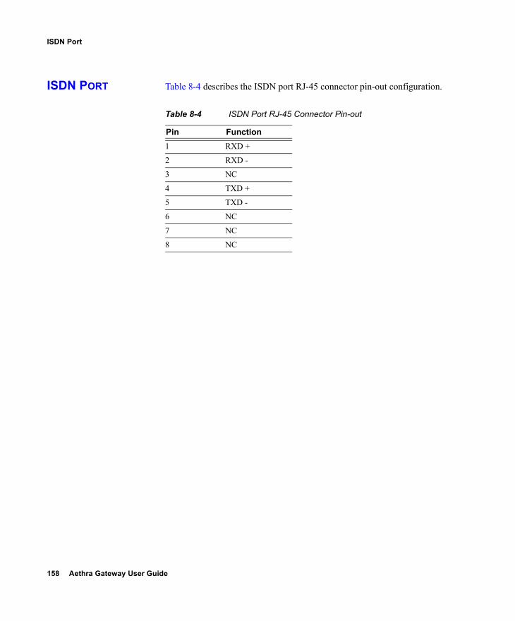
158 Aethra Gateway User Guide
ISDN Port
ISDN PORT Table 8-4 describes the ISDN port RJ-45 connector pin-out configuration.
Table 8-4 ISDN Port RJ-45 Connector Pin-out
Pin Function1 RXD +
2 RXD -
3 NC
4 TXD +
5 TXD -
6 NC
7 NC
8 NC
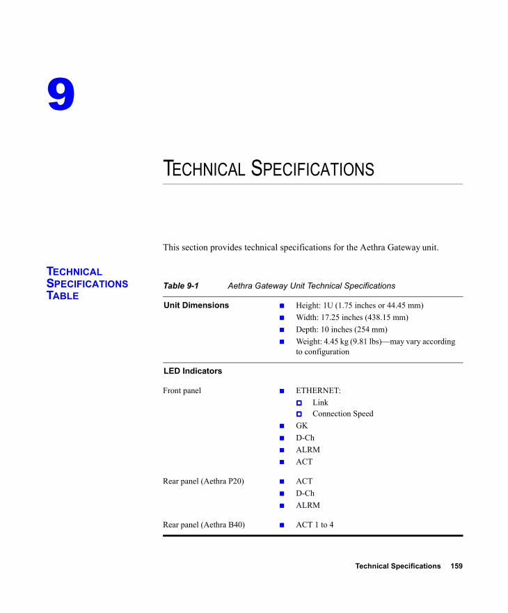
Technical Specifications 159
9TECHNICAL SPECIFICATIONS
This section provides technical specifications for the Aethra Gateway unit.
TECHNICAL SPECIFICATIONS TABLE
Table 9-1 Aethra Gateway Unit Technical Specifications
Unit Dimensions Height: 1U (1.75 inches or 44.45 mm) Width: 17.25 inches (438.15 mm) Depth: 10 inches (254 mm) Weight: 4.45 kg (9.81 lbs)—may vary according
to configuration
LED Indicators
Front panel ETHERNET: Link Connection Speed
GK D-Ch ALRM ACT
Rear panel (Aethra P20) ACT D-Ch ALRM
Rear panel (Aethra B40) ACT 1 to 4
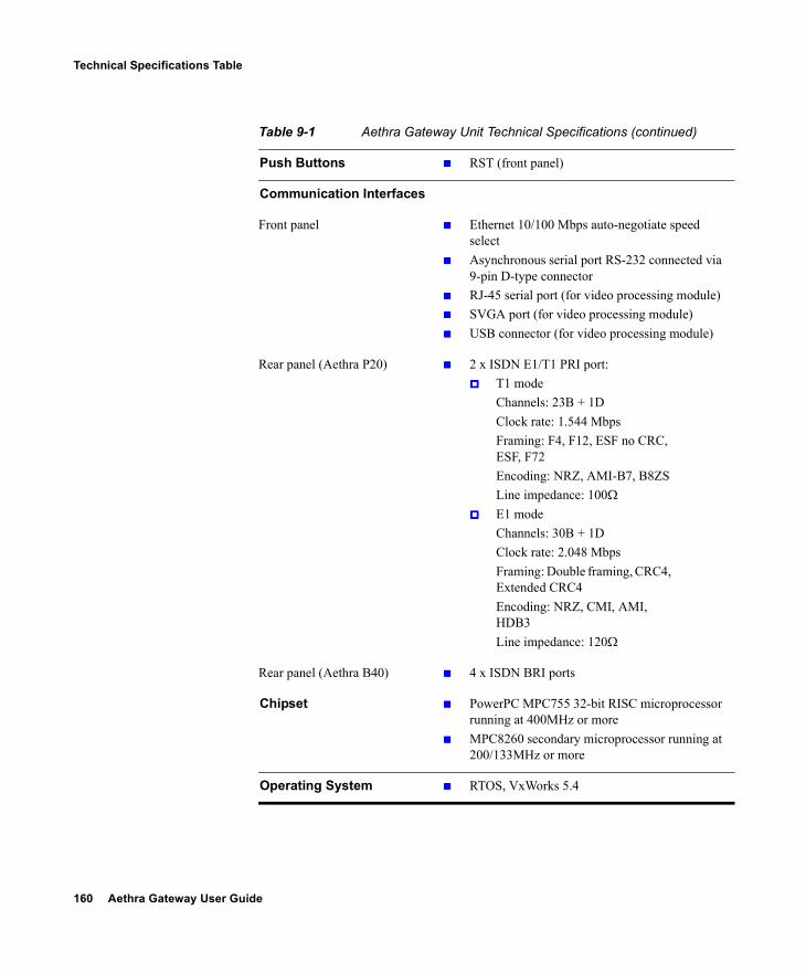
160 Aethra Gateway User Guide
Technical Specifications Table
Push Buttons RST (front panel)
Communication Interfaces
Front panel Ethernet 10/100 Mbps auto-negotiate speed select
Asynchronous serial port RS-232 connected via 9-pin D-type connector
RJ-45 serial port (for video processing module) SVGA port (for video processing module) USB connector (for video processing module)
Rear panel (Aethra P20) 2 x ISDN E1/T1 PRI port: T1 mode
Channels: 23B + 1D Clock rate: 1.544 MbpsFraming: F4, F12, ESF no CRC, ESF, F72Encoding: NRZ, AMI-B7, B8ZS Line impedance: 100Ω
E1 modeChannels: 30B + 1D Clock rate: 2.048 MbpsFraming: Double framing, CRC4, Extended CRC4Encoding: NRZ, CMI, AMI, HDB3Line impedance: 120Ω
Rear panel (Aethra B40) 4 x ISDN BRI ports
Chipset PowerPC MPC755 32-bit RISC microprocessor running at 400MHz or more
MPC8260 secondary microprocessor running at 200/133MHz or more
Operating System RTOS, VxWorks 5.4
Table 9-1 Aethra Gateway Unit Technical Specifications (continued)
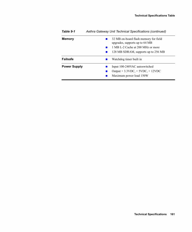
Technical Specifications 161
Technical Specifications Table
Memory 32 MB on-board flash memory for field upgrades, supports up to 64 MB
1 MB L-2 Cache at 200 MHz or more 128 MB SDRAM, supports up to 256 MB
Failsafe Watchdog timer built in
Power Supply Input 100-240VAC autoswitched Output + 3.3VDC, + 5VDC, + 12VDC Maximum power load 150W
Table 9-1 Aethra Gateway Unit Technical Specifications (continued)

Compliance and Certifications 163
10COMPLIANCE AND CERTIFICATIONS
This section provides certifications that have been approved for the Aethra Gateway, including the following topics:
Safety Compliance EMC Telecom Environment
SAFETY COMPLIANCE
This section lists the safety standards supported by the Aethra Gateway unit. UL 60950: 2000 CAN/CSA C22.2 No. 60950-00 GS Approval (EN 60950: 2000) EN 60950: 2000 ACA TS001-1997 AS/NZS 3260: 1993, A4: 1997 AS/NZS 60950: 2000 IEC 60950: 1999 (CB test report)
EMC This section lists the EMC compliance for the Aethra Gateway unit. FCC Part 15, Subpart B, Class A ICES-003 EN 55022: 1998, Class A EN 55024: 1998
164 Aethra Gateway User Guide
EMC
EN 61000-3-2: 1995, Amendment A14: 2000 EN 61000-3-3: 1995 IEC 61000-4-2: 1995 IEC 61000-4-3: 1995 IEC 61000-4-4: 1995 IEC 61000-4-5: 1995 IEC 61000-4-6: 1996 IEC 61000-4-8: 1993 IEC 61000-4-11: 1994 AS/NZS 3548: 1995, Class A, Amendment 1: 1997, Amendment 2:
1997
Warning This is a class A product. In a domestic environment this product may cause radio interference in which case the user may be required to take adequate measures.
FCC PART 15 NOTICE This section provides RF interference information for the user. This equipment has been tested and found to comply with the limits for a Class A digital device, pursuant to Part 15 of the FCC rules. These limits are designed to provide reasonable protection against harmful interference when the equipment is operated in a commercial environment. This equipment generates, uses, and can radiate radio frequency energy and, if not installed and used in accordance with the instruction manual, may cause harmful interference to radio communications. Operation of this equipment in a residential area is likely to cause harmful interference, in which case the user will be required to correct the interference at one’s own expense.
Warning Changes or modifications to the device that are not approved by the party responsible for compliance could void the user’s authority to operate the equipment.
Compliance and Certifications 165
Telecom
TELECOM This section lists standards compliance for products that connect to ISDN lines. ACTA Part 68 Industry Canada CE CTR3, CE CTR4
ACTA PART 68 NOTICE
1 This equipment complies with ACTA Part 68. On the cover of this equipment is a label that contains, among other information, the ACTA registration number. If requested, this information must be provided to the telephone company.
2 Applicable registration jack USOCs (Universal Service Order Codes) for the equipment is RJ48C for PRI interfaces and RJ49C for BRI interfaces.
3 An FCC compliant telephone cord and modular plug is provided with equipment. This equipment is designated to be connected to the telephone network or premises wiring using a compatible modular jack which is Part 68 compliant. See Installation Instructions for details.
4 If the terminal equipment Aethra Gateway causes harm to the telephone network, the telephone company will notify you in advance that temporary discontinuance of service may be required. But if advance notice is not practical, the telephone company will notify the customer as soon as possible. Also, you will be advised of your right to file a complaint with the FCC if you believe it is necessary.
5 The telephone company may make changes in its facilities, equipment, operations or procedures that could affect the operation of the equipment. If this happens, the telephone company will provide advance notice in order for you to make necessary modifications to maintain uninterrupted service.
6 If trouble is experienced with the Aethra Gateway equipment, please contact Aethra SpA customer support at (+39) 0712189900 for information on service or repairs. If the equipment is causing harm to the telephone network, the telephone company may request that you disconnect the equipment until the problem is resolved.
7 The Facility Interface Codes are: 04DU9-BN; 04DU9-DN; 04DU9-1SN. The Service Order Code is: 6.0N.
166 Aethra Gateway User Guide
Environment
8 Only Aethra SpA qualified service personnel may repair the equipment.
INDUSTRY CANADA The Industry Canada (IC) label identifies certified equipment. This certification means that the equipment meets certain telecommunications network protective, operational and safety requirements. The IC does not guarantee the equipment will operate to the user's satisfaction.Before installing this equipment, users should ensure that it is permissible to be connected to the facilities of the local telecommunications company. The equipment must also be installed using an acceptable method of connection. In some cases, the company's inside wiring associated with a single line individual service may be extended by means of a certified connector assembly (telephone extension cord). The customer should be aware that compliance with the above condition may not prevent degradation of service in some situations.Repairs to some certified equipment should be made by an authorized maintenance facility designated by the supplier. Any repairs or alterations made by the user to this equipment, or equipment malfunctions, may give the telecommunications company cause to request the user to disconnect the equipment.Users should ensure for their own protection that the ground connections of the power utility, telephone lines and internal metallic water pipe system, are connected together. This precaution may be particularly important in rural areas.The abbreviation, IC, before the registration number signifies that registration was performed based on a Declaration of Conformity indicating that Industry Canada technical specifications were met. It does not imply that Industry Canada approved the equipment.
Warning Users should not attempt to make such connections themselves, but should contact the appropriate electric inspection authority, or electrician, as appropriate.
ENVIRONMENT Aethra complies with the following EU Directives: Restrictions on the Use of Hazardous Substances (RoHS) Directive
2002/95/EC Waste Electrical and Electronic Equipment (WEEE) Directive
2002/96/EC

Safety 167
11SAFETY
This section describes safety procedures and requirements for operating the Aethra Gateway, including the following topics:
Electrical Safety ESD Procedures
ELECTRICAL SAFETY
To avoid an electric shock or damage to the Aethra Gateway unit, servicing should be performed by qualified service personnel only. To reduce the risk of damaging power surges, Aethra recommends installing an AC surge arrestor in the AC outlet from which the Aethra Gateway unit is powered.
Warning Do not attempt to open the Aethra Gateway unit.
Warning Changes or modifications to the device that are not approved by the party responsible for compliance could void the user’s authority to operate the equipment.
168 Aethra Gateway User Guide
ESD Procedures
GROUNDING The power cable of the Aethra Gateway unit should only be connected to a power outlet that has a protective earth contact. Do not use an extension cord that does not have a protective conductor (ground). The Aethra Gateway unit can become dangerous if you interrupt any of the protective conductors (grounding) or disconnect any of the protective earth terminals.
HIGH VOLTAGE Disconnect the Aethra Gateway unit from the power line before removing the cover. Avoid any adjustment, maintenance, or repair of an opened chassis under voltage. These actions should only be carried out by a skilled person who is aware of the dangers involved. Capacitors inside the chassis may still be charged, even if the unit has been disconnected from the power source.
ESD PROCEDURES To prevent damage to the Aethra Gateway unit by random electrostatic discharge (ESD), the use of wrist straps is highly recommended.
Index 169
AAAAaccess control 3access levels 34ACT LED 18, 19, 20Add ISDN Information Elements dialog box
98, 100, 104Add peer dialog box 52Add User dialog box 34address information 40Addressing tab 39, 40administrator access level 34Administrator interface 29advanced commands 83–85Advanced Commands dialog box 85Advanced dialog box 88, 89, 93, 94, 95, 96advanced settings 73AES See encryptionalert indications 64ALRM LED 18, 19audio codecs 5, 57
enable 59Audio Message Utility procedures
exit 147install and launch utility 142play message 143record message 144replace message 145upload message 146use Express Setup 148view message details 147
audio messages available 143audio transcoding 5, 45, 57, 59, 71, 113auto dial 75
auto-boot 22
BBBBbandwidth 71, 86, 110
call overhead 15resource allocation 15supported 6
basic settings 47Basics tab 36, 37, 38, 39board basic settings 39bonding
calls 7synchronization 88
boot configuration menu 22BRI
call handling capacity 15connecting gateway directly to central office
switch 13connecting gateway directly to PBX 13ISDN connections 11ports 94
BRI LINE connectors 20
CCCCcables
RJ-45 8-pin IP network port 157RJ-45 serial port adapter 157RS-232 9-pin serial port 156
call bandwidth overhead 15call bearer rate 74call details 111–113call handling
BRI gateway capacity 15
INDEX
170 Aethra Gateway User Guide
capabilities 6PRI gateway capacity 14
Calls tab 110, 111, 113Certifications
EMC 163Telecom 165
Change Time dialog box 38chipset 160Choose file dialog box 117communication interfaces 160conceal caller ID 3, 74, 76configuration procedures
add interface users 34add service 87change address settings 40change Administrator interface web server
port 41configure advanced commands 85configure advanced settings 73configure basic port settings 90configure basic settings 47configure bonding synchronization 88configure downspeeding 61configure DTMF settings 82configure encoding and decoding
protocols 59configure encryption settings 73configure fractional channels 92configure framing 93configure incoming call routing methods
108configure IVR 55configure line coding 93configure NSF settings 106configure outgoing call delimiters 56configure peer- to-peer connectivity 50configure physical line properties for BRI
port 94configure port call policies 108configure port physical line properties 91configure port supported services 110configure QoS settings 63configure security 41configure signaling type 93
configure SPID values 96delete interface users 35delete ISDN information elements 108delete services 89detect DTMF 82disconnect calls 113edit interface users 34edit service 87import configuration files 116refresh call information 111refresh information 46register with gatekeeper 48reserve resources 71restore board basic settings 39save configuration settings 116select events for SNMP traps 64set location 38set time and date 37update license 37
connectorsBRI line 20Ethernet 18PRI line 19serial port 18, 28
DDDDdata collaboration 2, 58, 70
enable T.120 60DB-9 7, 18, 28D-Ch LED 18, 19decoding 59default bit rate 75default extension 3, 95, 109, 124default services 86delimiters
outgoing calls 56second number 56, 120
DES See encryptionDetails dialog box 46diagnostics 2dial plan 3dialing
indirectly through an operator 126
Index 171
into IP 122out from IP 119through IVR 125
dialing examples 120–126DID 3, 76, 95, 108, 123direct dialing 3Discovered Gatekeepers dialog box 49downspeeding 4, 60, 66, 69, 83DTMF 3, 66, 68, 79, 80
convert signals 81detection 81tone assignments 80
dual video 3, 79, 112, 113
EEEEE1/T1 11, 15, 91, 92Edit ISDN Information Elements dialog box
98, 104Edit peer dialog box 52Edit User dialog box 35EMC 163encoding 59encryption 72
H.235 4, 73Ethernet
10/100Base-T 7connector 18
Ethernet LED 19Event Log tab 114Express Setup 147external program access 41
FFFFfailsafe 161fast start 4, 77feature summary
general features 2FECC 60File Download dialog box 116first-time installation 29fractional channels 92
Fractional dialog box 92, 93framing 93front panel 18FTP 41
GGGGgatekeeper
registering 48GK LED 18
HHHHH.239 4, 79H.243 5H.323
call disconnect reason 54, 84fast start 4, 77version 1 49version 2 or later 49
IIIIICMP 41importing files 116incoming call routing methods 108, 122initial configuration 22installation requirements 20interoperability 2IP address assign 24IP network connection 5, 7ISDN
connection failure 4rollover 4
IVR 3, 55, 76corrupt files 66, 69internal capacity 7operator 125routing 108, 124
LLLLLAN 18, 27
10/100Base-T 7
172 Aethra Gateway User Guide
LED indicators 18, 19, 20, 159troubleshooting 129
LED Monitoring tab 35license
update 37Licensing and Registration dialog box 37line coding 93line quality 7local
configuration 28monitoring 28
location 38
MMMMmaintenance mode 115Maintenance tab 115MCU 79memory 161MSN 3, 123multimedia conferencing 8multipoint conferencing 10
NNNNNetscape Navigator 31network jitter tolerance field 77network load balancing 2Network Specific Facility (NSF) 4, 106NSF Configuration dialog box 98, 107
OOOOonline help 30operating system 160operator access level 34
PPPPpackage contents 21password
default login user 26peer-to-peer
connectivity 5, 16, 48, 50disconnect 54, 84hunting module 54peer hunting mode 51
physical descriptiongateway 18
physical line properties 94pin-out configuration
ISDN port RJ-45 connector 158RJ-45 IP network port 157RS-232 9-pin D-type serial port 156
pin-to-pin configurationRJ-45 to DB-9 adapter cable 157
point-to-point conferencing 10Port Specific tab 89Port tabs 89ports
BRI 94IRJ-45 8-pin ISDN 157physical line properties 91PRI 91RJ-45 IP 157RJ-45 serial 157RS-232 9-pin serial 156settings 90supported 5supported services 109SVGA 28
power supply 161presentation restriction 74, 76, 79PRI
call handling capacity 14connecting gateway directly to central office
switch 12connecting gateway to a PBX 12interface features 7ISDN connections 11ports 91
PRI LINE connectors 19PRI Port tab 97push buttons 160
Index 173
QQQQQ.931 3, 74, 76, 77, 99, 107Quality of Service (QoS) 2, 62
RRRRrack mounting 21read-only access level 34rear panel 19rear panel components 20refresh 46remote
management 28requirements 24
installation 20resources 71RJ-45 18, 19, 20, 28rollover 4, 67, 69, 78routing 3, 108, 122RS-232
DTE 9-pin D-type connection 7RST button 18, 160
SSSSSafety
compliance 163electrical 167ESD procedures 168
saving configuration settings 116second number delimiter 56, 120security 41Security tab 41serial control port 7serial port connector 18, 28
DB-9 28services 86, 109
default 86prefix 86, 109, 119user defined 86
Services tab 74, 86, 87
Settings tab 44, 47, 48, 50, 55, 56, 59, 60, 63, 64, 70, 73, 82, 88, 89
setup proceduresaccess Administrator interface 29change default password 26connect to a PC 23connect unit to LAN 27mount unit on a 19-inch rack 21register online help 30set IP address 24
signaling protocols 7, 91, 94signaling type 93SNMP 41
management 2, 28trap events 64, 65, 68trap servers 4trap severity enumerations 70
software upgrade utility proceduresinstall and launch 152use utility 152
software upgrades 28SPID 96SPIDs dialog box 97Statistics tab 114Status tab 45, 46stripping 105sub-addressing 76, 123SVGA 28switch information 7
TTTTT.120 58, 70
data collaboration 2enable 76
TCS4 3, 57, 108, 122, 124Telecom 165time and date 37troubleshooting
echo cancellation 137Ethernet port settings 135Ethernet port speed 139factory defaults 135, 139
174 Aethra Gateway User Guide
global user name and password 135, 137IP address problems 127LED indication problems 129making calls 131networking information 135receiving calls 132remote monitoring 135T.120 data collaboration 138web server port setting 138
troubleshooting proceduresaccess device commands through serial
port 136assign IP address to a new gateway 128change global user name and password
137configure speed of Ethernet port 139configure web server port 138monitor gateway functions from remote
site 135restore factory default settings 139set echo cancellation 137set T.120 data collaboration capability 138
Type of Number (TON) fields 105Type of Service (TOS) 62
UUUUunit dimensions 159upgrade software 151user-defined services 86Users tab 34, 35
VVVVVersion Details dialog box 37video conferencing protocols 5video protocols 6
enable H.263, H.263+,H.264 60video resolutions 6viewing
audio message details 147B channel status 46call details 111call information 110
general information 36LED information 35reported alarm events 114service details 86services on each port 109software version details 37system-specific information 114
WWWWweb files 66, 69web server 41Web tab 30, 41web-based management 2


