24
Transformer bushings GOE 2600 for rated voltage 1200 kV Installation and maintenance guide 1ZSC000563-AAF en, Rev. 2

Transformer bushings GOE 2600 for rated voltage 1200 kVInstallation and maintenance guide
1ZSC000563-AAF en, Rev. 2

Original instruction
The information provided in this document is intended to be general and does not cover all possible applications. Any specific application not covered should be referred directly to ABB, or its authorized representative.
ABB makes no warranty or representation and assumes no liability for the accuracy of the information in this document or for the use of such information. All information in this document is subject to change without notice.
This document must not be copied without our written permission, and the contents thereof must not be imparted to a third party nor be used for any unauthorized purpose. Contravention will be prosecuted.

Safety informationKeep this instruction available to those responsible for the installation, maintenance, and operation of the bushing.
The installation, operation, and maintenance of a bushing present numerous potential unsafe conditions, including, but not limited to, the following:
– High pressures – Lethal voltages – Moving machinery – Heavy components – Slip, stumble or fall
Specialized procedures and instructions are required and must be adhered to when working on such apparatus. Failure to follow the instructions could result in severe personal injury, death, and/or product or property damage.
Additionally, all applicable safety procedures such as regional or local safety rules and regulations, safe working practices, and good judgement must be used by the personnel when installing, operating, maintaining and/or disposing such equipment.
Safety, as defined in this instruction, involves two conditions:
1. Personal injury or death.2. Product or property damage (includes damage to the
bushing or other property, and reduced bushing life).
Safety notations are intended to alert personnel of possible personal injury, death or property damage. They have been inserted in the instructional text prior to the step in which the condition is cited.
The following warnings and notes are used in the manual:
WARNING
WARNING indicates an imminently hazardous situation, which if not avoided, will result in death or serious injury. This signal word is to be limited to the most extreme situations.
WARNING also indicates a potentially hazardous situation which, if not avoided, could result in death or serious injury.
CAUTION
CAUTION indicates a potentially hazardous situation,which if not avoided, may result in minor or moderate injury. It may also be used to alert of unsafe practices.
CAUTION may also indicate property-damage-only hazards.
INFO provides additional information to assist in carrying out the work described and to provide trouble-free operation.


Content1 Description ........................................................................................................... 6
1.1 Design ......................................................................................................... 61.2 Operating conditions ..................................................................................... 81.3 Mechanical loading ....................................................................................... 81.4 Spare parts .................................................................................................. 8
2 Lifting equipment and installation ........................................................................... 92.1 Lifting equipment .......................................................................................... 9
2.1.1 Overview ................................................................................................ 92.1.2 Handling of the lifting equipment ............................................................. 102.1.3 Erection on the reactor/transformer ......................................................... 112.1.2.1 Vertical mounting ................................................................................. 122.1.2.2 Inclined mounting ................................................................................ 122.1.3 Maintenance ........................................................................................... 13
2.2 Transport box ............................................................................................... 132.3 Transport and handling ................................................................................. 142.4 Inspection of the bushing when lifting it from the transport box ....................... 142.5 Bottom contact with threaded holes (N1= 4) for cable lugs ...............................142.6 Draw rod ...................................................................................................... 162.7 Mounting of outer terminal ............................................................................ 192.8 Flange earthing ............................................................................................. 202.9 Waiting time before energizing ....................................................................... 202.10 Recommended tests before energizing ........................................................ 20
2.10.1 Tightness test between transformer and bushing flange .......................... 202.10.2 Tightness test of bushing outer terminal ................................................. 202.10.3 Measurement of capacitance and tan δ .................................................. 212.10.4 Check of through resistance .................................................................. 21
3 Maintenance ......................................................................................................... 223.1 Recommended maintenance and supervision ................................................. 22
3.1.1 Cleaning of insulator surface ................................................................... 223.1.2 Measurement of capacitance and tan δ .................................................... 223.1.3 Thermovision (infrared camera) check for local overheating on connectors 223.1.4 Check for leakage ................................................................................... 223.1.5 Checking and adjustment of the oil level .................................................. 22
3.2 Oil sampling from bushing ............................................................................. 223.3 Disposal after end of service life ................................................................. 23

6 Installation and maintenance guide GOE 2600 | 1ZSC000563-AAF en, Rev. 2
1
3
2
1 Description
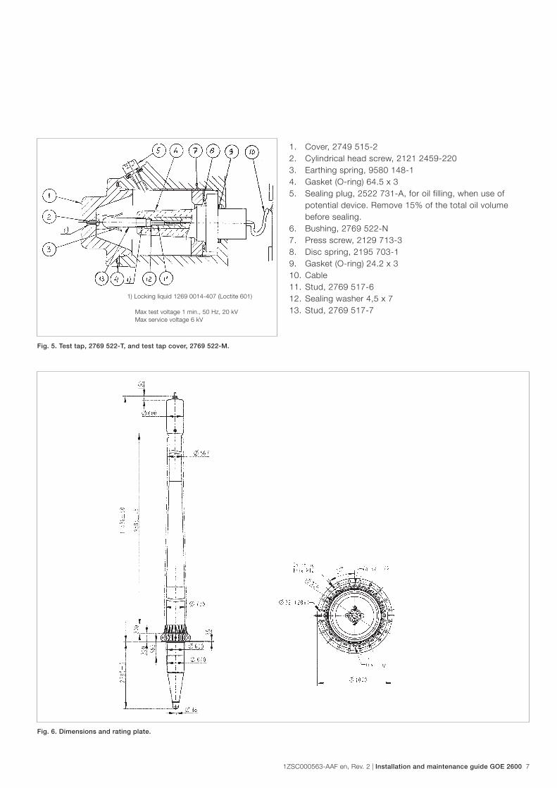
1.1 DesignThe design principle of bushing type GOE 2600 is shown in Figs. 1-4. GOE bushings have a voltage test tap, according to Fig. 5, which can be used for checking of the bushing insulation by capa citance and dissipation factor measurements in service. The test tap is earthed via the test tap cover.
Fig. 1. Design principle.Top end nut
1. Top end nut2. Flexible connection3. Top housing4. Oil level gauge (complete with gasket and screws),
Magnetic type, 2744 322-B5. Porcelain insulator, air side6. Pre-stressed tubes7. Transformer oil8. Condenser body10. Mounting flange11. Extension for current transformers12. Porcelain insulator, oil side13. Bottom end nut14. Sealing plug (not for oil sampling!)
a. M8; 2522 731-Ab. M16; 2522 731-B
Fig. 2. Air side porcelain shed shape.
Oil level, A, see section 3.1.5
Fig. 4. Sealing plug, 2522 731-B.
1. Bolt, 2121 2033-5922. Conical spring washer, 2154 725-73. Gasket, 2152 045-513
Fig. 3. Sealing plug, 2522 731-A.
1. Bolt with flange DIN 6921, 2121 738-182. Gasket, 2152 899-132
1ZSC000563-AAF en, Rev. 2 | Installation and maintenance guide GOE 2600 7
Fig. 5. Test tap, 2769 522-T, and test tap cover, 2769 522-M.
1) Locking liquid 1269 0014-407 (Loctite 601) Max test voltage 1 min., 50 Hz, 20 kV Max service voltage 6 kV
1. Cover, 2749 515-22. Cylindrical head screw, 2121 2459-2203. Earthing spring, 9580 148-14. Gasket (O-ring) 64.5 x 35. Sealing plug, 2522 731-A, for oil filling, when use of
potential device. Remove 15% of the total oil volume before sealing.
6. Bushing, 2769 522-N7. Press screw, 2129 713-38. Disc spring, 2195 703-19. Gasket (O-ring) 24.2 x 3 10. Cable11. Stud, 2769 517-612. Sealing washer 4,5 x 713. Stud, 2769 517-7
Fig. 6. Dimensions and rating plate.

8 Installation and maintenance guide GOE 2600 | 1ZSC000563-AAF en, Rev. 2
1.2 Operating conditionsThe table below show the standard technical specifications for the GOE oil - air bushings. For conditions exceeding the below values, please contact ABB.
Application: Transformers, reactors
Classification: Oil impregnated paper, capacitance
graded, outdoor-immersed bushing
Ambient temperature: +40 to -40 °C, minimum value as per
temperature class 2 of IEC 60137
Altitude of site: < 1 000 m
Level of rain and humidity: 1-2 mm rain/min horizontally and vertically,
as per
IEC 60060-1
Type of immersion medium: Transformer oil. Maximum daily mean oil
temperature 90 °C. Maximum temporary oil
temperature 115 °C.
Oil level in transformer: Not lower than 30 mm from the bushing
flange.
Max. pressure of
surrounding medium:
100 kPa overpressure
Markings: Conforming to IEC
1.3 Mechanical loadingThe bushings are designed for the following cantilever loads applied to the midpoint of the top terminal, perpendicularly to the bushing axis. In axial direction the GOE bushing can withstand 20 kN continuously. The maximum torque on the outer terminal stud is 250 Nm.
Table 1. Mechanical loading.
Bushing Max. test load
1 minute (N)
Max. permissible load (N) in
operation at mounting angle 0°
GOE 2600 8000 2500
1.4 Spare partsIn case of major damage to the bushing we recommend that it is sent back to ABB for possible repair and re-testing. Certain parts which may be damaged or lost during transport or installation, can be ordered from ABB.

1ZSC000563-AAF en, Rev. 2 | Installation and maintenance guide GOE 2600 9
2 Lifting equipment and installation
Fig. 7. Placement of lifting devices for GOE 2600.
Fig. 8. Lifting devices.
2.1 Lifting equipment2.1.1 Overview
PDV1909-1PDV1909-2
PDV1909-4

10 Installation and maintenance guide GOE 2600 | 1ZSC000563-AAF en, Rev. 2
2.1.2 Handling of the lifting equipmentLifting equipment is intended for raising and lifting in connection with mounting of bushing type GOE2600 (ABB Power Products, Components). Two cranes are needed for erection of the bushing. The maximum bushing weight of 6000 kg is not allowed to exceed.
Fig. 9. Lifting equipment PDV1909-2 is fixed to the bushings flange with four screws and nuts dimension M30x90 of min strength 8.8.
Fig. 10. Liftting bushing horizontally. Lifting equipment PDV1909-2 range of use to lift bushings horizontal.
1ZSC000563-AAF en, Rev. 2 | Installation and maintenance guide GOE 2600 11
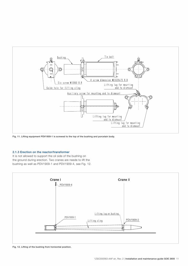
Fig. 11. Lifting equipment PDV1909-1 is screwed to the top of the bushing and porcelain body.
2.1.3 Erection on the reactor/transformerIt is not allowed to support the oil side of the bushing on the ground during erection. Two cranes are neede to lift the bushing as well as PDV1909-1 and PDV1909-4, see Fig. 12.
Fig. 12. Lifting of the bushing from horizontal position.

12 Installation and maintenance guide GOE 2600 | 1ZSC000563-AAF en, Rev. 2
2.1.2.1 Vertical mountingIf the bushing is to be placed vertically, crane II and PDV1909-2 should be removed when the bushing has been placed in vertical position, see Fig. 13.
Fig. 13. Vertical mounting of the bushing.
Fig. 14. Inclined mounting of the bushing, when PDV1909-2 and crane II
have been removed.
2.1.2.2 Inclined mountingIf the bushing is to be mounted inclined, a tackle should be mounted already before the bushing is lifted. Everything else should be as per Fig. 12. After lifting to horizontal, the bushing should be inclined with the cranes and the tackle should be used to place the bushing in the final position. Dismount PDV1909-2 and crane II before mounting the bushing.
1ZSC000563-AAF en, Rev. 2 | Installation and maintenance guide GOE 2600 13
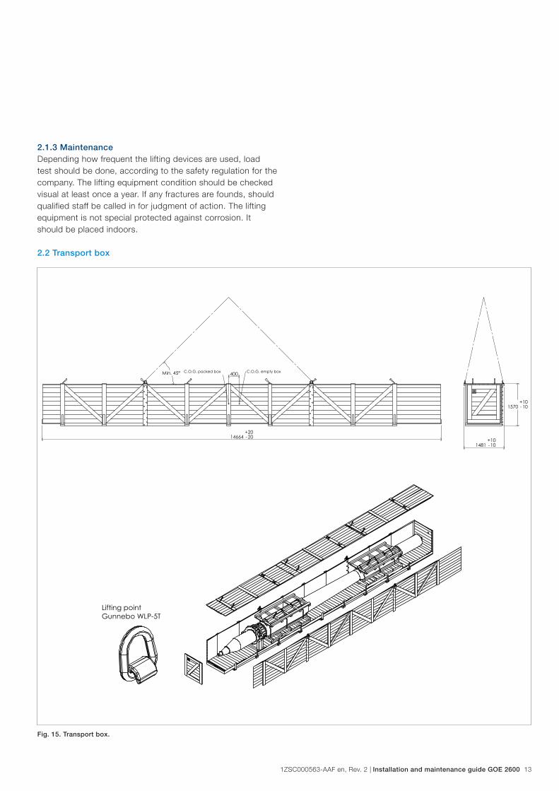
Fig. 15. Transport box.
2.1.3 MaintenanceDepending how frequent the lifting devices are used, load test should be done, according to the safety regulation for the company. The lifting equipment condition should be checked visual at least once a year. If any fractures are founds, should qualified staff be called in for judgment of action. The lifting equipment is not special protected against corrosion. It should be placed indoors.
2.2 Transport box
14 Installation and maintenance guide GOE 2600 | 1ZSC000563-AAF en, Rev. 2
2.3 Transport and handlingAll transports of the bushing shall be made in the transport box.
The bushing may be transported and stored horizontally up to 6 months. For storing over 6 months it is recommended to raise the bushing to vertical position with the top end upwards or inclined position with the top end upwards and at an angle of at least 7°. Keep the bushings dry and clean and protected against mechanical damage.
Keep the bushings protected from penetrating water when stored outdoors. This means that the case must not be stored in areas where it can be foreseen that the ground will be wet and muddy during heavy rains. Shelter the case from rain and snow with a tarpaulin or roofing.
Carefully inspect the bushing on receiving with regard to shipping damage. Please note that the bushing has been routine tested partly submerged in oil and some oil may be left. Vaseline is used for lubrication of threads, and at some temperatures the vaseline may appear as oil.
The bushings are normally delivered from ABB in boxes with the bushing supported by cellular plastic blocks and fibre boards. The boxes are marked with "Top End".
2.4 Inspection of the bushing when lifting it from the transport box1. Maker a visual inspection of the transport box for
damages.2. After opening the transport box check that bushing is still
in position and not moved axial direction.3. After lifting the bushing out of the transport box check if
any transport damages can be seen on the bushing. 4. Check that the oil conservator is centrally placed in
relation to the air side porcelain. 5. Check if there is any oil at the gaskets or at any other
place. If oil is found, the place should be carefully cleaned and rechecked after 6 hours.
If transport damages have been found, check the impact recorder by pressing the button on it to see if any impacts are above the acceptance criteria. If the impact level has been exceeded the following should also be made:
1. Check that the K1 distance is 14 mm ± 2 mm. See Fig. 17.
2. Check bushing tan δ.3. Check bushing capacitance C1.
2.5 Bottom contact with threaded holes (N1= 4) for cable lugsConnect the cable lugs to the bottom contact. Tightening torque 68 ± 6 Nm.
It is extremely important that the cables do not provide any tension and thus do not apply any extra force to the bottom contact.

1ZSC000563-AAF en, Rev. 2 | Installation and maintenance guide GOE 2600 15
Fig. 16. Long-term storage.
Min. 7°
"Top End"
Fig. 17. K1 dimension.
Fig. 18. Connecting to bottom contact.
6. Cable lugs8. Connections to the winding9. Shielding tube10. Bottom contact with holes M12, thread insert with locking
turn

16 Installation and maintenance guide GOE 2600 | 1ZSC000563-AAF en, Rev. 2
Fig. 19. Draw rod system.
2.6 Draw rod
Mounting of the draw rod must be performed according to the procedure below. The contact surfaces must be clean.
The parts below the transformer cover are usually supported in the transport cover as shown in Fig. 20. At erection the smaller cover shall be opened first and the support for the connection parts loosened. The bigger transport cover is then removed.
1. As shown in Fig. 21, the compensating device is placed on top of the bushing inner tube.
2. The additional jointing sleeve shall be locked with locking fluid (Loctite 242 and activator Loctite T747) at site in order to avoid an unintended loosening of this joint at an eventual dismounting of the draw rod system later on. Fig. 22 shows how the joints are locked by delivery.
3. The cord, pulled through the bushing with the compensating device (7), the washer (4), the nut (3), and the box spanner (2) in place, is used for lowering of the upper part of the draw rod to the correct position for jointing with the threaded sleeve to the lower end part.
4. The bushing is then lowered into the transformer with the cord well stretched.
If fixed stud bolts are used for fastening of the bushing flange, it is recommended to apply plastic sleeves on 2 or 3 of the studs in order to guide the flange and prevent cutting of metal chips, which may fall down into the transformer.

1ZSC000563-AAF en, Rev. 2 | Installation and maintenance guide GOE 2600 17
Fig. 20. Example of suspension for inner terminals for draw rod during
transport.
1. Smaller cover2. Transport cover3. Transformer cover4. Draw rod5. Spacer tube6. Bottom contact7. Connection to the winding
Fig. 21. Assembly of draw rod system.
1. Flexible pull-through cord acc. to Fig. 82. Box spanner acc. to Fig. 93. Hexagon nut M164. Washer 17 x 45 x 35. Extension acc. to Fig. 86. Draw rod7. Compensating device8. Lifting gear acc. to Fig. 69. Hexagon head screw M10 x 5010. Jointing sleeve, 2126 739-3
Top end of bushing
5 washers
Mount according to section "Draw rod"
18 Installation and maintenance guide GOE 2600 | 1ZSC000563-AAF en, Rev. 2
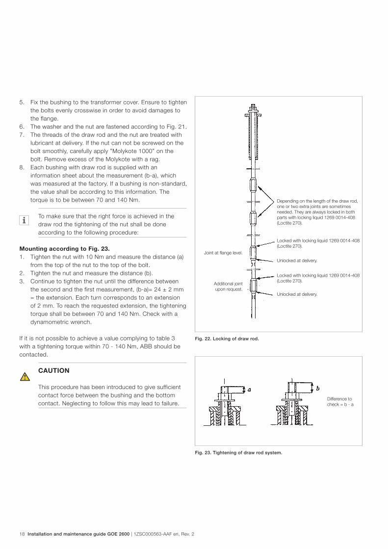
Fig. 22. Locking of draw rod.
Depending on the length of the draw rod, one or two extra joints are sometimes needed. They are always locked in both parts with locking liquid 1269 0014-408 (Loctite 270).
Locked with locking liquid 1269 0014-408 (Loctite 270).
Locked with locking liquid 1269 0014-408 (Loctite 270).
Unlocked at delivery.
Unlocked at delivery.
Joint at flange level.
Additional joint upon request.
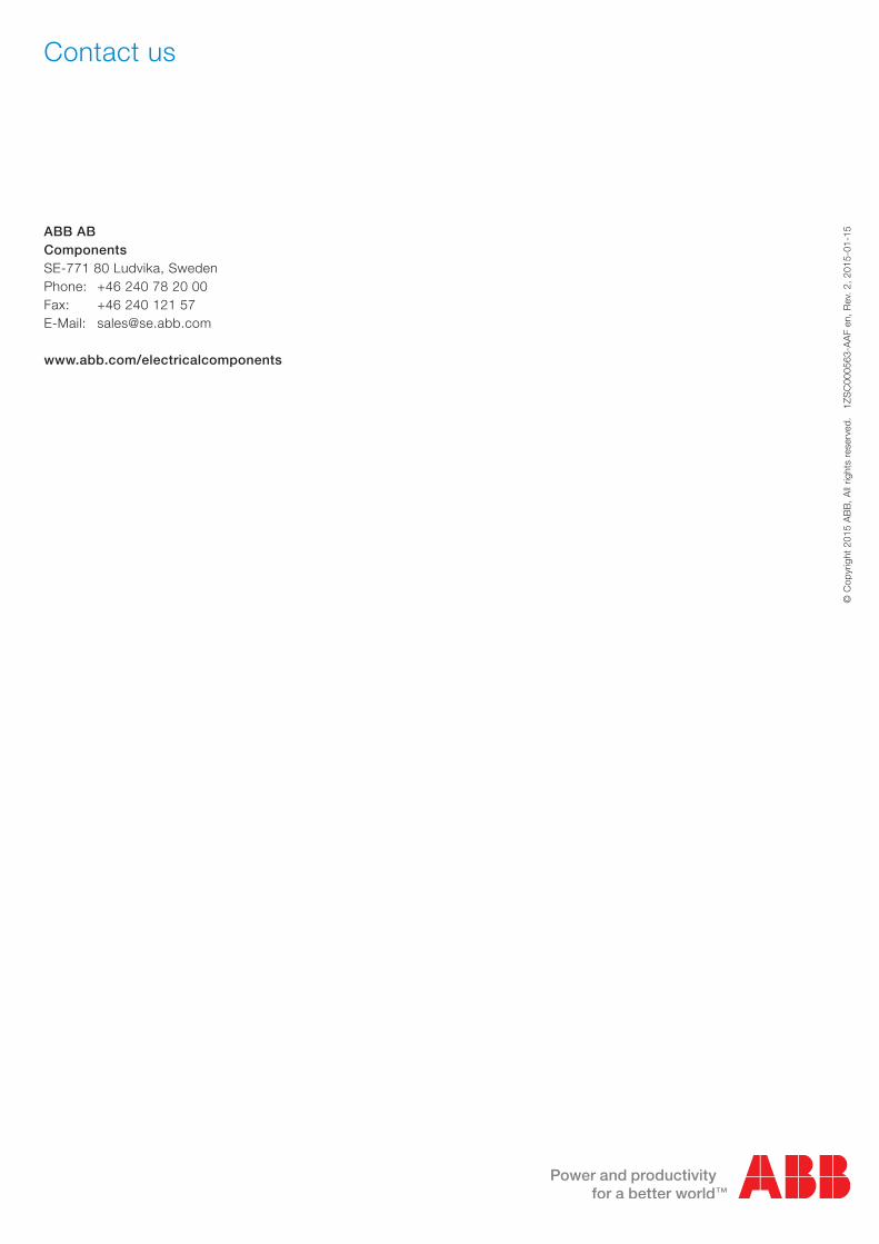
Difference to check = b - a
Fig. 23. Tightening of draw rod system.
5. Fix the bushing to the transformer cover. Ensure to tighten the bolts evenly crosswise in order to avoid damages to the flange.
6. The washer and the nut are fastened according to Fig. 21.7. The threads of the draw rod and the nut are treated with
lubricant at delivery. If the nut can not be screwed on the bolt smoothly, carefully apply ”Molykote 1000” on the bolt. Remove excess of the Molykote with a rag.
8. Each bushing with draw rod is supplied with an information sheet about the measurement (b-a), which was measured at the factory. If a bushing is non-standard, the value shall be according to this information. The torque is to be between 70 and 140 Nm.
To make sure that the right force is achieved in the draw rod the tightening of the nut shall be done according to the following procedure:
Mounting according to Fig. 23.1. Tighten the nut with 10 Nm and measure the distance (a)
from the top of the nut to the top of the bolt.2. Tighten the nut and measure the distance (b).3. Continue to tighten the nut until the difference between
the second and the first measurement, (b-a)= 24 ± 2 mm = the extension. Each turn corresponds to an extension of 2 mm. To reach the requested extension, the tightening torque shall be between 70 and 140 Nm. Check with a dynamometric wrench.
If it is not possible to achieve a value complying to table 3 with a tightening torque within 70 - 140 Nm, ABB should be contacted.
CAUTION
This procedure has been introduced to give sufficient contact force between the bushing and the bottom contact. Neglecting to follow this may lead to failure.

1ZSC000563-AAF en, Rev. 2 | Installation and maintenance guide GOE 2600 19
2.7 Mounting of outer terminal
The inner contact surfaces of aluminium, both on the bushing tube and on the terminal stud, are tin plated and wire brushing must thus not be carried out.
In order to obtain the correct pressure and a low contact resistance, the following must be carried out:
1. Clean the contact and gasket surfaces carefully.2. Lubricate the O-ring (6) with Mobilgrease 28.3. Assemble the retainer ring, the gasket (O-ring) (6), and the
terminal stud on the bushing tube.4. Grease all bolts on thread and underneath the head with
Molykote 1000, or other suitable compound.
Fig. 24. Mounting of outer terminal with corona ring.
1. Terminal stud2. Hexagon screw, M8 x 403. Hexagon screw, M10 x 65, ABB article no. 9ADA 58-304. Conical spring washer, 8.4 x 18 x 1 (Belleville)5. Plane washer, 10.5 x 22 x 26. Gasket (O-ring), 99.1 x 5.77. Retainer ring for gasket
5. Mount the corona ring on the terminal stud.6. Mount the plane washers and the new, longer screws
M10 x 65, which press the stud against the bushing tube. Tighten the screws by steps to a final torque of 40 ±4 Nm.
7. Mount the conical spring washers (4) and the screws M8, which hold the retainer ring. Tighten the screws to press the gasket into place. Tighten by steps to a final torque of 20 ±2 Nm.
It is extremely important in both cases to tighten evenly. The bolts shall thus be tightened by steps, alternately on both sides.

20 Installation and maintenance guide GOE 2600 | 1ZSC000563-AAF en, Rev. 2
2.8 Flange earthing
CAUTION
Proper earthing is essential.
The bushing flange is provided with a tapped hole M12. After tightening the bolts fixing the bushing to the transformer tank, the flange should be earthed. This prevents electrical discharges between bushing flange and transformer tank under normal service conditions.
Alternative 1Insert a heavily greased (Mobilgrease 28 recommended) pointed set screw M12 (stainless steel A4-80 preferrably). Tighten to 40 Nm, penetrating the paint of the transformer tank down to the metal underneath. This makes an electrical connection between the bushing and the transformer tank, keeping them at the same voltage.
Alternative 2Apply a flexible cable between the M12 earthing hole in the bushing flange and a corresponding connection point in the transformer. Grease the screw (Mobilgrease 28 recommended) and tighten the M12 in the bushing to 40 Nm. Connect the other end of the cable to the transformer.
2.9 Waiting time before energizing
When a bushing has been stored horizontally, it must be raised with the top up for at least 12 hours before service voltage is applied and 24 hours before test voltage is applied. If, by mistake, the bushing has been stored horizontally more than one year, it must be placed in the vertical position for at least one week before energizing. Some waiting time may be necessary before energizing in order to avoid flashovers or partial discharges due to airbubbles at the bushing surface. Choose a suitable procedure below.
Vacuum filled transformerNo waiting time is necessary from the bushing point of view.
De-gassed oil-filled transformerDuring mounting, use a clean and dry paintbrush to release surface bubbles. Wait 6 hours before energizing.
Gas-saturated oil-filled transformerDuring mounting, use a clean and dry paintbrush to release surface bubbles. Wait 24 hours before energizing.
De-gassed oil filled transformer with reduced oil-levelAfter restoring the oil-level, wait 24 hours before energizing.
For all alternatives except vacuum-filled transformer, the oil should be allowed to enter the centre tube to at least flange height by releasing the outer terminal sealing system and allowing air to escape this way.
2.10 Recommended tests before energizingThe following tests may be performed to check the insulation, sealing and current path of the bushing. The tests should be made after mounting, but before connecting the outer terminal of the bushing to the rest of the switchyard power circuit.
2.10.1 Tightness test between transformer and bushing flangeSeveral different methods may be used and we thus refer to instructions given by the company responsible for the field erection. As a simple example, the tightness of the seal between transformer and bushing flange may be checked when the transformer is oil-filled by using chalk or, perhaps easier, with paper strips.
2.10.2 Tightness test of bushing outer terminalSince the top terminal is often situated above the oil level of the transformer expansion system, a leak at this point is extremely serious, because water could enter directly into the transformer insulation this way. It is thus recommended to make a tightness test after assembly, preferably both with vacuum and over-pres sure. Several different methods may be used and we refer to instructions given by the firm responsible for the field erection.
One possible method is the tracer gas method:
1. Put a tracer gas into the centre tube before mounting the outer terminal. The oil level of the transformer must be above the bottom end of the bushing but below the bushing flange.
2. Increase the pressure in the center tube by increasing the oil level as much as possible.
3. Search with a gas detector (sniffer) for leaking gas at the gasket.

1ZSC000563-AAF en, Rev. 2 | Installation and maintenance guide GOE 2600 21
2.10.3 Measurement of capacitance and tan δ
CAUTION
Since C2 usually is relatively small, the test tap must never be open-circuited when applying a voltage to the bushing. It must always be earthed or connected to an external impedance.
After testing, check that the test tap cover is mounted correctly on the bushing.
After mounting, a capacitance measurement is recommended. A measu ring bridge is connected between the outer terminal and the test tap. This is possible without removing the bushing from the transformer as the bushing has an insulated test tap, see Fig. 4. More details can be found in product information 2750 515-142, "Bushing diagnostics and conditioning".
With the transformer de-energised and the bushing outer terminal dis connected, the test tap cover is removed. The measuring equip ment is connected to the test tap and the measuring voltage source is connected to the bushing terminal.
The capacitances C1 between the bushing conductor and the tap, and the capacitance C2, between the test tap and earth are marked on the nameplate. C2 is highly dependent on the surrounding parts inside the transformer and it is not possible to give a nominal value valid for all service conditions.
C1 = 740 pF ±10 %
C2 = only as information = 6000 pF ±50 %
The dissipation factor varies with the temperature of the bushing body and the measured value should thus be multiplied with the correction factor (multiplier) given in Table 2.
Table 2. Dissipation factor variations as a function of temperature.
Bushing body temperature °C Multiplier to 20 °C
3-7 0.85
8-12 0.90
13-17 0.95
18-22 1.00
23-27 1.05
28-32 1.10
33-37 1.15
38-42 1.20
43-47 1.25
48-52 1.30
2.10.4 Check of through resistanceThis method can be used to detect very large faults in the current path, such as disruptions, and is not a tool for diagnostic of the bushing.
The through-resistance measurement method depends on the design of the transformer. Generally, a current is applied from bushing to bushing. The voltage drop from outer terminal to outer terminal is measured. The resistance is calculated with Ohm’s law, U = R·I. (U: Measured voltage drop. I: Through current. R: Total circuit resistance.)
The total through resistance is the sum of the transformer winding and lead resistance and the bushing conductor and contact resistance. The additional resistance from the bushing conductor should not be more than 200 µΩ. Since the through resistance of the HV winding of a typical power transformer is in the order of 0.1 ..1 Ω, this is a very rough method that can only be used to detect very large faults in the current path, such as disruptions.
Less-than-perfect contacts can only be detected by making a sensitive measurement across each connection point, or by measuring the temperature increase during operation with an infrared sensitive camera (thermovision).

22 Installation and maintenance guide GOE 2600 | 1ZSC000563-AAF en, Rev. 2
3 Maintenance
The GOE bushings are maintenance-free. For bushings with oil-level indicator, it is recommended to note the oil level during normal routine inspections in the plant.
WARNING
No work at all can be performed on the bushing while it is energized or not earthed.
3.1 Recommended maintenance and supervision3.1.1 Cleaning of insulator surface
Avoid having solvent on the bushing gasket and porcelain joints
Under conditions of extreme pollution it may be necessary to clean the porcelain insulator surface. This should be done by water-jet or by wiping with a moist cloth. If necessary, ethyl-alcohol or ethyl-acetate may be used.
3.1.2 Measurement of capacitance and tan δPlease refer to Chapter 2.10.3.
3.1.3 Thermovision (infrared camera) check for local overheating on connectors At maximum rated current, the bushing outer terminal normally takes a temperature of about 35 to 45 °C above the ambient air. Significantly higher temperatures, especially at lower current loading, can be a sign of bad connections.
3.1.4 Check for leakageMake a visual inspection for oil leakage during normal station supervision.
3.1.5 Checking and adjustment of the oil levelBushings with magnetic oil level indication have the indication arrranged to show that the oil level does not reach the minimum level. The oil level at normal and high temperatures should always be above the red area on the indicator. If the oil level is too low, clean and dry transformer oil must be added. For the correct oil level A, according to Fig. 3, please contact ABB. Adjustment of oil level is allowed only when the temperature of the bushing is +5 °C to +35 °C. It is recommended that the sealing plug be provided with a new gasket after the check. The sealing plug is to be tightened with 20 Nm.
3.2 Oil sampling from bushingThe bushing flange is equipped with an oil sampling valve that has a 1/2" connection. The connection on this valve should be used for oil sampling so that no pressure from the bushing is released.
Oil samples shall preferable be taken during dry weather conditions. If, by some urgent reason, the sample is taken at any other condition the following shall be taken into account:
– Dry and clean the area around the sampling valve carefully before the sampling.
– Protect the area around the sampling valve from rain.
The internal pressure of the bushing must not be altered before and after the sampling as the bushing is supposed to work within a specified interval.
The time when the bushing is unsealed shall be as short as possible. Flushing with dry air or nitrogen is normally not necessary.
Maximum 2 dm3 oil as allowed to take out from the housing during its liftetime. If more oil is taken out it must be replaced by the same volume of new transformer oil. The new oil shall comply to IEC 60296 and shall be clean and dry.
Fig. 25. Checking of the oil level.

1ZSC000563-AAF en, Rev. 2 | Installation and maintenance guide GOE 2600 23
Fig. 26. Oil sampling valve with a R 1/2" connection.
3.3 Disposal after end of service lifeThe bushing consists of the following material:
– Conductor tube of low-alloy aluminium. – Terminals of copper, brass or low-alloy aluminium may be
plated with for instance silver, tin, gold or nickel in layer thickness up to 20 µm.
– Transformer oil as per IEC 60296. – Transformer oil impregnated condenser body consists of
paper and 1 % Al foils. – Top housing, top end nut, test tap and flexible connection
consist of Al alloys. – Flange may be designed of aluminium or welded steel. – Press ring for oil level glass consists of plated brass. – Prism glass consists of glass. – Insulators consist of quartz or alumino silicate based
porcelain.
Sampling procedure for bushings with sampling valve on the flange:Connect the end of the hose to a suitable nipple and connect the nipple to the valve on the flange. The thread in the valve is (R 1/2") BSPT 1/2". Suck out the oil. After the sampling is finished the bushing shall not be energized within 12 hours.
For more information and interpretation of the oil samples, see IEC 61464.
Contact us
© C
opyr
ight
201
5 A
BB
, A
ll rig
hts
rese
rved
.
1ZS
C00
0563
-AA
F en
, R
ev.
2, 2
015-
01-1
5ABB AB ComponentsSE-771 80 Ludvika, Sweden Phone: +46 240 78 20 00 Fax: +46 240 121 57 E-Mail: [email protected] www.abb.com/electricalcomponents


