Page 1
© A. Benso - all rights reserved Version 1.0 2.1.1
2.1 – Introduction to Complex FSMs DesignCSE 142
Introduction to Complex FSMs
DesignAlfredo BENSO
Politecnico di Torino (Italy)UCSD, CA
[email protected]
22.1
Goal
• This section presents a design methodology to perform Manual Synthesis of Complex Finite State Machines.
Page 2
© A. Benso - all rights reserved Version 1.0 2.1.2
2.1 – Introduction to Complex FSMs DesignCSE 142
32.1
Prerequisites
• Simple FSM• RT-level design
42.1
Outline
• Introduction
• The concept of RT-state
• RT-state based synthesis
• Some examples
• The concept of macro RT-state.
Page 3
© A. Benso - all rights reserved Version 1.0 2.1.3
2.1 – Introduction to Complex FSMs DesignCSE 142
52.1
Levels of abstraction in VLSI design
• A design of a digital circuit requires a transformation from a "concept" to an "implementation“, in a series of ordered levels.
• From the highest level to lower levels of design "abstraction", a design is iteratively refined.
• The design description is verified and validated at each level, often cycling between levels of abstraction.
• Design descriptions are described using one or more domain representations (Behavior, Structure, Physical).
62.1
Levels of abstraction in VLSI design
Architectural Algorithm
Behavioral
RTL
Structural
Geometrical
Queuing networkBlock diagramPetri Nets
Flowchart
State equationState diagram
RTL notationDatapathTruth tables
Schematic diagramNetlist
Layoutmasks
Page 4
© A. Benso - all rights reserved Version 1.0 2.1.4
2.1 – Introduction to Complex FSMs DesignCSE 142
72.1
What’s a Complex FSM?
There isn’t a formal definition of Complex Finite State Machine.We can say that we need a Complex FSM when the simple FSM formalism or the RT-level approach are not powerful enough to describe the circuit we want to design.
82.1
Simple FSM formalism
The behavior of a simple FSM is specified using states in order to implement a Mealy or a Moore machine.
This formalism is very powerful for small designs, but it becomes too complex when dealing with complex designs.
For example, imagine the complexity of designing a system requiring a memory, a counter, a comparator, and a timer, just using Moore or Mealy states.
Page 5
© A. Benso - all rights reserved Version 1.0 2.1.5
2.1 – Introduction to Complex FSMs DesignCSE 142
92.1
RT-level approach
Designing an RT-level circuit, means to connect together standard components (memories, registers, counters, etc…) in order to obtain a system that behaves as desired.
This approach is useful for simple designs involving standard functionalities, but it is very limited if we want to design custom circuits with not standard functionalities.
102.1
What’s a Complex FSM?
A Complex FSM is a system including a Control Unit (designed as a FSM) and a Data Path(designed as an RT-level circuit) that are integrated together in order to implement complex functionalities.
The final description will include a structural (RTL) view of the Data Path + a logic-level specification of the Control Unit)
Page 6
© A. Benso - all rights reserved Version 1.0 2.1.6
2.1 – Introduction to Complex FSMs DesignCSE 142
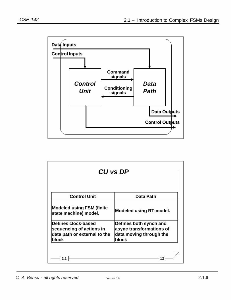
ControlUnit
DataPath
Data Inputs
Data Outputs
ControI Inputs
Control Outputs
Commandsignals
Conditioningsignals
122.1
CU vs DP
Defines both synch and async transformations of data moving through the block
Defines clock-based sequencing of actions in data path or external to the block
Modeled using RT-model.Modeled using FSM (finite state machine) model.
Data PathControl Unit
Page 7
© A. Benso - all rights reserved Version 1.0 2.1.7
2.1 – Introduction to Complex FSMs DesignCSE 142
132.1
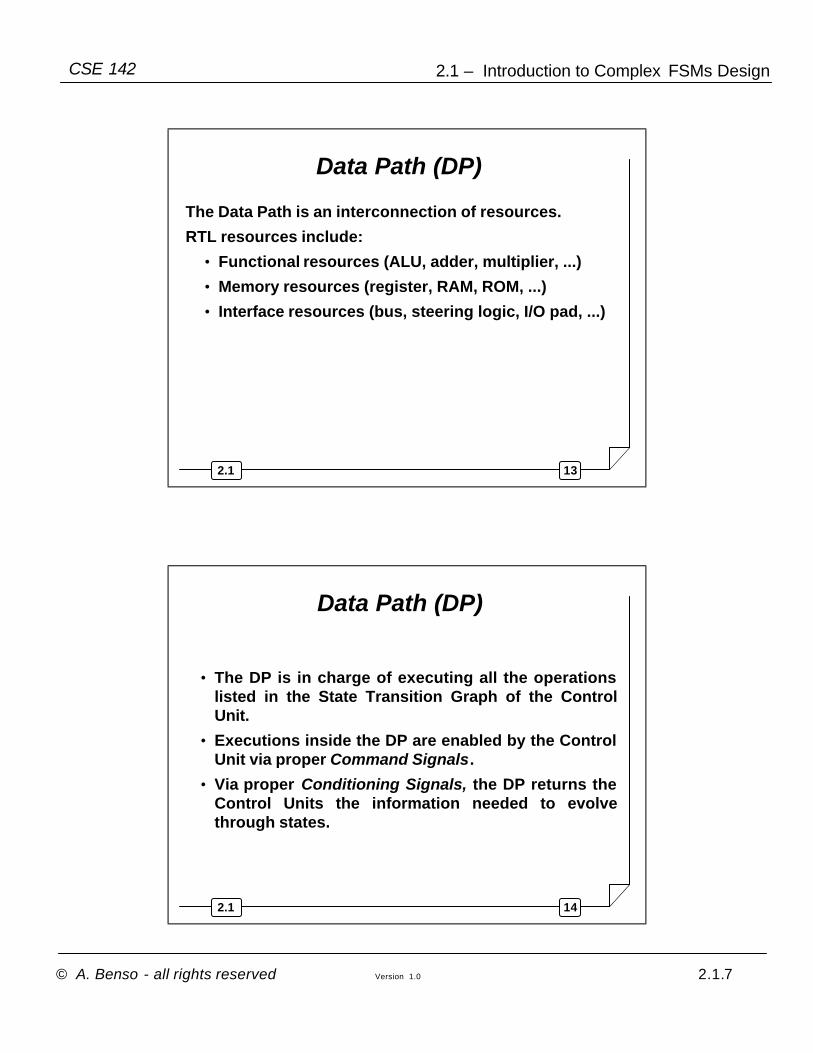
Data Path (DP)
The Data Path is an interconnection of resources.
RTL resources include:
• Functional resources (ALU, adder, multiplier, ...)
• Memory resources (register, RAM, ROM, ...)
• Interface resources (bus, steering logic, I/O pad, ...)
142.1
Data Path (DP)
• The DP is in charge of executing all the operations listed in the State Transition Graph of the Control Unit.
• Executions inside the DP are enabled by the Control Unit via proper Command Signals.
• Via proper Conditioning Signals, the DP returns the Control Units the information needed to evolve through states.
Page 8
© A. Benso - all rights reserved Version 1.0 2.1.8
2.1 – Introduction to Complex FSMs DesignCSE 142
152.1
Data Path (DP)
• Data Path and Control Unit are synchronized using clock signals
• Benefits of synchronization:
• Eliminate unpredictability of output behavior due to timing skew.
• Create signal stability, as they must have stable values for certain period of time.
• Better isolate signals from noise transients.
• Controller sequences operations in the data path.
162.1
Control Unit
• On the basis of the values of
− Present state
− Control Inputs
− Conditioning signal provided by the DP
on each state it determines:
− its next state
− the set of Command Signals needed to enable the set of concurrent operations the DP has to perform on the next rising edge of the clock.
Page 9
© A. Benso - all rights reserved Version 1.0 2.1.9
2.1 – Introduction to Complex FSMs DesignCSE 142
172.1
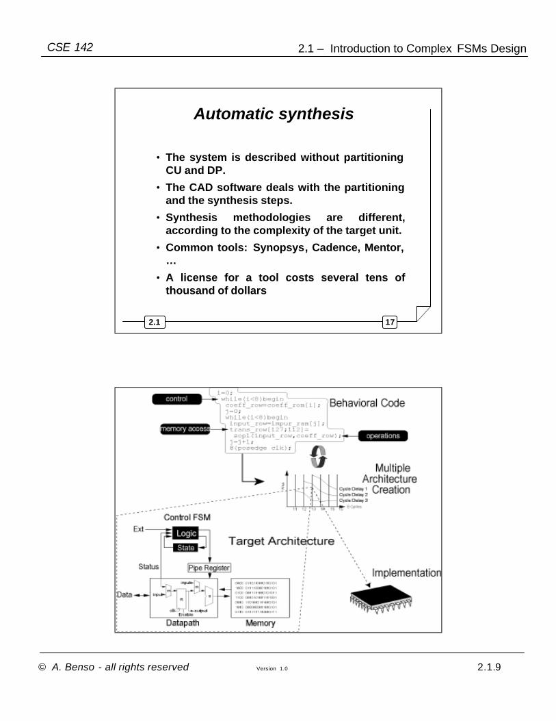
Automatic synthesis
• The system is described without partitioning CU and DP.
• The CAD software deals with the partitioning and the synthesis steps.
• Synthesis methodologies are different, according to the complexity of the target unit.
• Common tools: Synopsys, Cadence, Mentor, …
• A license for a tool costs several tens of thousand of dollars
182.1
Page 10
© A. Benso - all rights reserved Version 1.0 2.1.10
2.1 – Introduction to Complex FSMs DesignCSE 142
192.1
202.1
Manual synthesis
• Each Unit is synthesized independently.
• Synthesis methodologies are different, according to the complexity of the target unit.
• The Data Path is synthesized first.
• The Control Unit is synthesized later, to guarantee the Data Path performs the required operations.
Page 11
© A. Benso - all rights reserved Version 1.0 2.1.11
2.1 – Introduction to Complex FSMs DesignCSE 142
212.1
Outline
• Introduction
• The concept of RT-state
• RT-state based synthesis
• Some examples
• The concept of macro RT-state.
222.1
Introduction
In targeting system level behavioral descriptions, it may be helpful resorting to the introduction of “states” the process evolves though.
Page 12
© A. Benso - all rights reserved Version 1.0 2.1.12
2.1 – Introduction to Complex FSMs DesignCSE 142
232.1
Introduction (cont’d)
• In each state, hereinafter referred to as RT-state, the system can perform several complex concurrent RT level operations
• The evolution between states is triggered by the master clock signal.
242.1
RT-state
A new graphical representation formalism needs to be introduced.
Page 13
© A. Benso - all rights reserved Version 1.0 2.1.13
2.1 – Introduction to Complex FSMs DesignCSE 142
252.1
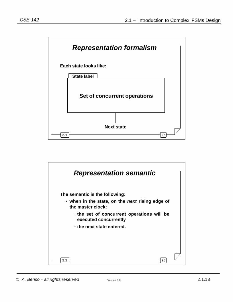
Representation formalism
Each state looks like:
Set of concurrent operations
State label
Next state
262.1
Representation semantic
The semantic is the following:• when in the state, on the next rising edge of
the master clock:
− the set of concurrent operations will be executed concurrently
− the next state entered.
Page 14
© A. Benso - all rights reserved Version 1.0 2.1.14
2.1 – Introduction to Complex FSMs DesignCSE 142
272.1
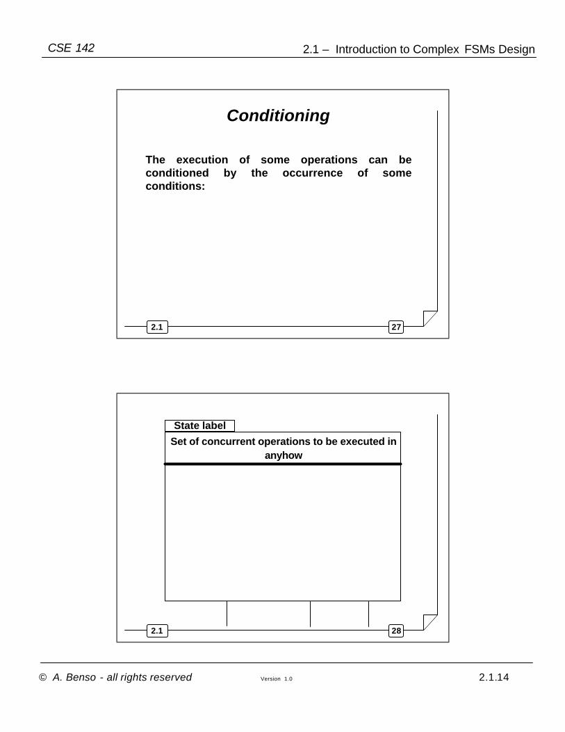
Conditioning
The execution of some operations can be conditioned by the occurrence of some conditions:
282.1
State label
Set of concurrent operations to be executed in anyhow
Page 15
© A. Benso - all rights reserved Version 1.0 2.1.15
2.1 – Introduction to Complex FSMs DesignCSE 142
292.1
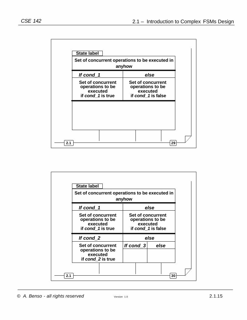
State label
Set of concurrent operations to be executed in anyhow
If cond_1 else Set of concurrent operations to be
executed if cond_1 is true
Set of concurrent operations to be
executed if cond_1 is false
302.1
State label
Set of concurrent operations to be executed in anyhow
If cond_1 else Set of concurrent operations to be
executed if cond_1 is true
Set of concurrent operations to be
executed if cond_1 is false
If cond_2
If cond_3
else
else Set of concurrent operations to be
executed if cond_2 is true
Page 16
© A. Benso - all rights reserved Version 1.0 2.1.16
2.1 – Introduction to Complex FSMs DesignCSE 142
312.1
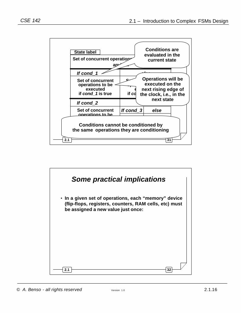
State label
Set of concurrent operations to be executed in anyhow
If cond_1 else Set of concurrent operations to be
executed if cond_1 is true
Set of concurrent operations to be
executed if cond_1 is false
If cond_2
If cond_3
else
else Set of concurrent operations to be
executed if cond_2 is true
Conditions are evaluated in the
current state
Operations will be executed on the
next rising edge of the clock, i.e., in the
next state
Conditions cannot be conditioned by the same operations they are conditioning
322.1
Some practical implications
• In a given set of operations, each “memory” device (flip-flops, registers, counters, RAM cells, etc) must be assigned a new value just once:
Page 17
© A. Benso - all rights reserved Version 1.0 2.1.17
2.1 – Introduction to Complex FSMs DesignCSE 142
332.1
Some practical implications
• In a given set of operations, each “memory” device (flip-flops, registers, counters, RAM cells, etc) must be assigned a new value just once:
…
A <= f( )
…
A <= g( )
…
342.1
Warning !!
• All the operations listed in a given set must be executed concurrently and in just one clock cycle !!
Page 18
© A. Benso - all rights reserved Version 1.0 2.1.18
2.1 – Introduction to Complex FSMs DesignCSE 142
352.1
Warning !!
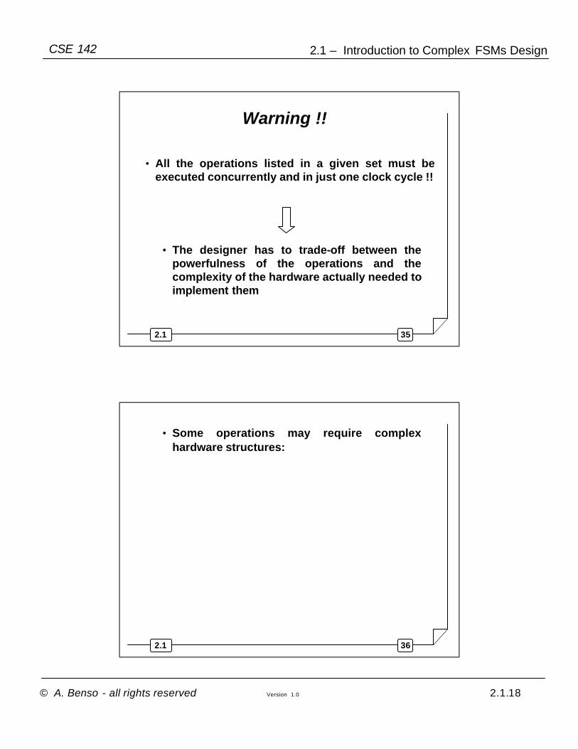
• All the operations listed in a given set must be executed concurrently and in just one clock cycle !!
• The designer has to trade-off between the powerfulness of the operations and the complexity of the hardware actually needed to implement them
362.1
• Some operations may require complex hardware structures:
Page 19
© A. Benso - all rights reserved Version 1.0 2.1.19
2.1 – Introduction to Complex FSMs DesignCSE 142
372.1
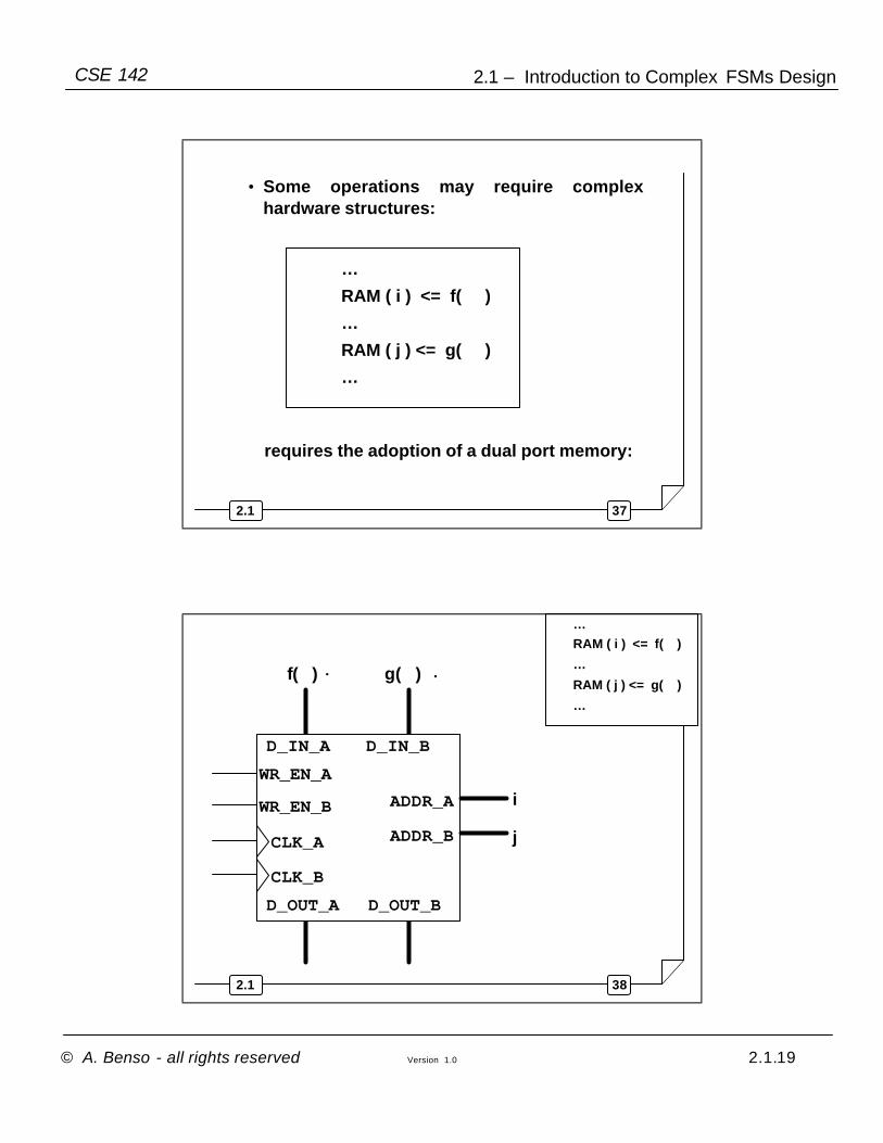
requires the adoption of a dual port memory:
…
RAM ( i ) <= f( )
…
RAM ( j ) <= g( )
…
• Some operations may require complex hardware structures:
382.1
ADDR_B
WR_EN_A
D_OUT_A
D_IN_A
CLK_A
ADDR_A
D_OUT_B
D_IN_B
WR_EN_B
CLK_B
…RAM ( i ) <= f( )
…
RAM ( j ) <= g( )
…
f( )
i
g( )
j
Page 20
© A. Benso - all rights reserved Version 1.0 2.1.20
2.1 – Introduction to Complex FSMs DesignCSE 142
392.1
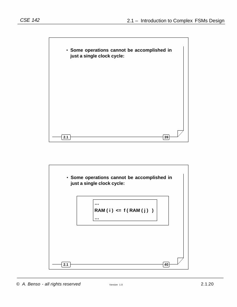
• Some operations cannot be accomplished in just a single clock cycle:
402.1
…
RAM ( i ) <= f ( RAM ( j ) )
…
• Some operations cannot be accomplished in just a single clock cycle:
Page 21
© A. Benso - all rights reserved Version 1.0 2.1.21
2.1 – Introduction to Complex FSMs DesignCSE 142
412.1
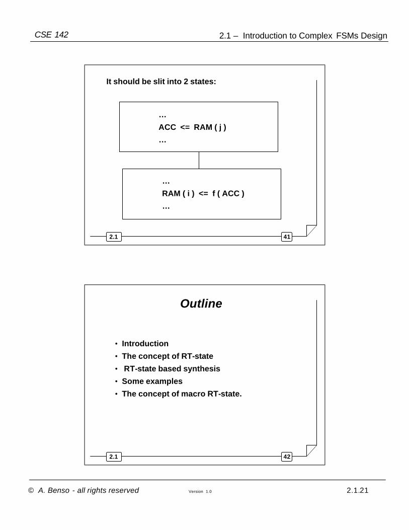
…
ACC <= RAM ( j )
…
…
RAM ( i ) <= f ( ACC )
…
It should be slit into 2 states:
422.1
Outline
• Introduction
• The concept of RT-state
• RT-state based synthesis
• Some examples
• The concept of macro RT-state.
Page 22
© A. Benso - all rights reserved Version 1.0 2.1.22
2.1 – Introduction to Complex FSMs DesignCSE 142
432.1
RT-state based synthesis
Several design methodologies exist for RT-state based system descriptions.There are two main approaches:
• VHDL-based :
− it relies on the availability of a VHDL synthesis tool. It will be not be covered in this course
• Purely manual:− it will be covered in this course
442.1
Outline
• Introduction
• The concept of RT-state
• RT-state based synthesis
• Some examples
• The concept of macro RT-state.
Page 23
© A. Benso - all rights reserved Version 1.0 2.1.23
2.1 – Introduction to Complex FSMs DesignCSE 142
452.1
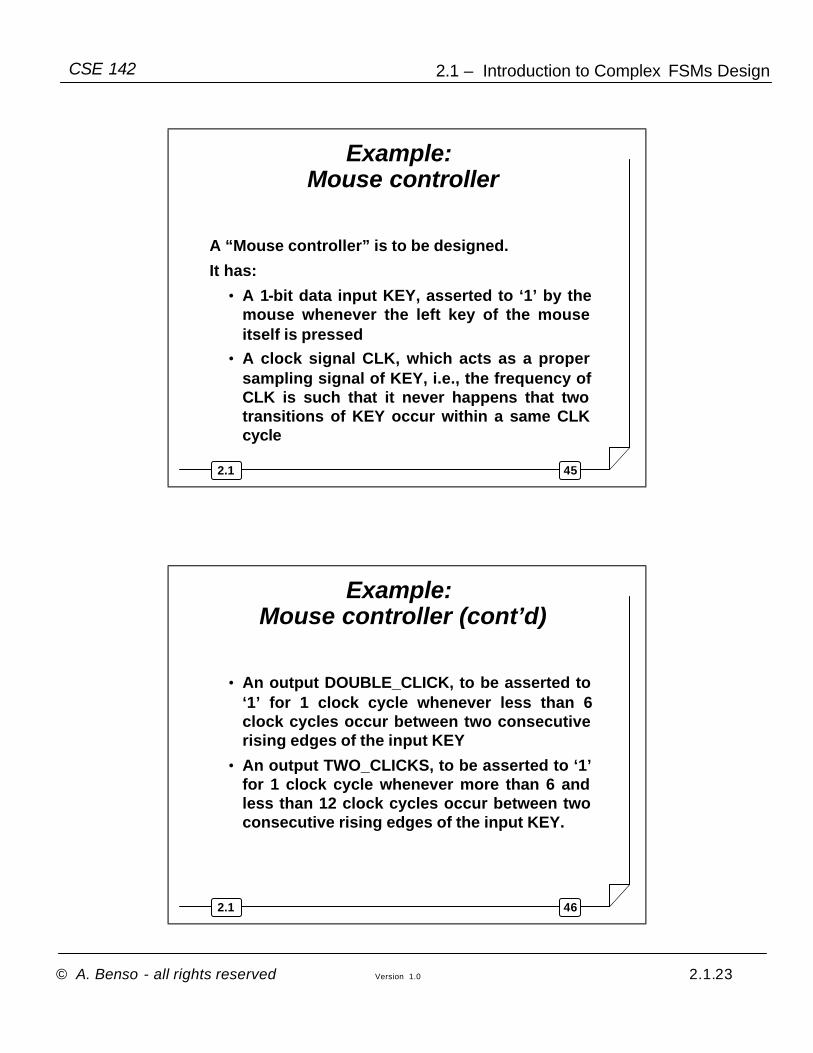
Example: Mouse controller
A “Mouse controller” is to be designed.
It has:
• A 1-bit data input KEY, asserted to ‘1’ by the mouse whenever the left key of the mouse itself is pressed
• A clock signal CLK, which acts as a proper sampling signal of KEY, i.e., the frequency of CLK is such that it never happens that two transitions of KEY occur within a same CLK cycle
462.1
Example: Mouse controller (cont’d)
• An output DOUBLE_CLICK, to be asserted to ‘1’ for 1 clock cycle whenever less than 6 clock cycles occur between two consecutive rising edges of the input KEY
• An output TWO_CLICKS, to be asserted to ‘1’ for 1 clock cycle whenever more than 6 and less than 12 clock cycles occur between two consecutive rising edges of the input KEY.
Page 24
© A. Benso - all rights reserved Version 1.0 2.1.24
2.1 – Introduction to Complex FSMs DesignCSE 142
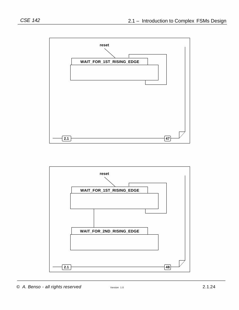
472.1
WAIT_FOR_1ST_RISING_EDGE
reset
482.1
WAIT_FOR_1ST_RISING_EDGE
WAIT_FOR_2ND_RISING_EDGE
reset
Page 25
© A. Benso - all rights reserved Version 1.0 2.1.25
2.1 – Introduction to Complex FSMs DesignCSE 142
492.1
WAIT_FOR_1ST_RISING_EDGE
WAIT_FOR_2ND_RISING_EDGE
reset
502.1
WAIT_FOR_1ST_RISING_EDGE
WAIT_FOR_2ND_RISING_EDGE
reset
Page 26
© A. Benso - all rights reserved Version 1.0 2.1.26
2.1 – Introduction to Complex FSMs DesignCSE 142
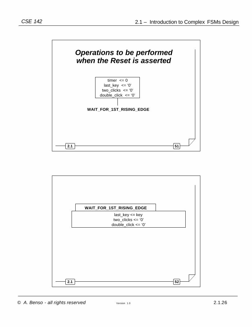
512.1
timer <= 0last_key <= ‘0’
two_clicks <= ‘0’double_click <= ‘0’
WAIT_FOR_1ST_RISING_EDGE
Operations to be performed when the Reset is asserted
522.1
WAIT_FOR_1ST_RISING_EDGE
last_key <= keytwo_clicks <= ‘0’
double_click <= ‘0’
Page 27
© A. Benso - all rights reserved Version 1.0 2.1.27
2.1 – Introduction to Complex FSMs DesignCSE 142
532.1
WAIT_FOR_1ST_RISING_EDGE
If rising edge on key[ key =‘1’ and last_key=‘0’ ]
else
last_key <= keytwo_clicks <= ‘0’
double_click <= ‘0’
542.1
WAIT_FOR_1ST_RISING_EDGE
If rising edge on key[ key =‘1’ and last_key=‘0’ ]
else
last_key <= keytwo_clicks <= ‘0’
double_click <= ‘0’
WAIT_FOR_2ND_RISING_EDGE
timer ++
Page 28
© A. Benso - all rights reserved Version 1.0 2.1.28
2.1 – Introduction to Complex FSMs DesignCSE 142
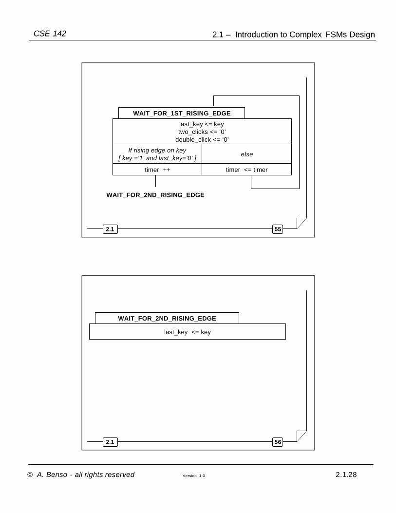
552.1
WAIT_FOR_1ST_RISING_EDGE
If rising edge on key[ key =‘1’ and last_key=‘0’ ]
else
last_key <= keytwo_clicks <= ‘0’
double_click <= ‘0’
WAIT_FOR_2ND_RISING_EDGE
timer ++ timer <= timer
562.1
WAIT_FOR_2ND_RISING_EDGE
last_key <= key
Page 29
© A. Benso - all rights reserved Version 1.0 2.1.29
2.1 – Introduction to Complex FSMs DesignCSE 142
572.1
WAIT_FOR_2ND_RISING_EDGE
If rising edge on key [ key =‘1’ and last_key=‘0’ ]
else
last_key <= key
582.1
If timer < 6 else
WAIT_FOR_2ND_RISING_EDGE
If rising edge on key [ key =‘1’ and last_key=‘0’ ]
else
last_key <= key
Page 30
© A. Benso - all rights reserved Version 1.0 2.1.30
2.1 – Introduction to Complex FSMs DesignCSE 142
592.1
If timer < 6 else
WAIT_FOR_1ST_RISING_EDGE
WAIT_FOR_2ND_RISING_EDGE
If rising edge on key [ key =‘1’ and last_key=‘0’ ]
else
double_click <= ‘1’ two_clicks <= ‘1’
last_key <= key
602.1
If timer < 6 else
WAIT_FOR_2ND_RISING_EDGE
If rising edge on key [ key =‘1’ and last_key=‘0’ ]
else
double_click <= ‘1’ two_clicks <= ‘1’
If timer < 12 else
last_key <= key
WAIT_FOR_1ST_RISING_EDGE
Page 31
© A. Benso - all rights reserved Version 1.0 2.1.31
2.1 – Introduction to Complex FSMs DesignCSE 142
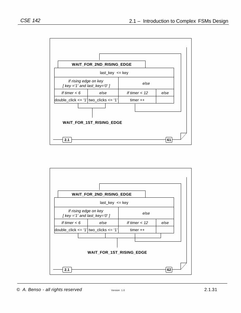
612.1
If timer < 6 else
WAIT_FOR_2ND_RISING_EDGE
If rising edge on key [ key =‘1’ and last_key=‘0’ ]
else
double_click <= ‘1’ two_clicks <= ‘1’
If timer < 12 else
timer ++
last_key <= key
WAIT_FOR_1ST_RISING_EDGE
622.1
If timer < 6 else
WAIT_FOR_1ST_RISING_EDGE
WAIT_FOR_2ND_RISING_EDGE
If rising edge on key [ key =‘1’ and last_key=‘0’ ]
else
double_click <= ‘1’ two_clicks <= ‘1’
If timer < 12 else
timer ++
last_key <= key
Page 32
© A. Benso - all rights reserved Version 1.0 2.1.32
2.1 – Introduction to Complex FSMs DesignCSE 142
632.1
Remarks
• The proposed solution requires much less states than a simple FSM
• The reason is that RT-states are more “powerful” in terms of expressiveness than STG-states (e.g., they can include conditions, counters, etc)
642.1
And the Data Path?
The Data Path has to be “extracted” from the RT-statesFrom the operations performed on the memory elements, we can choose the best RT component to use in the DP
Page 33
© A. Benso - all rights reserved Version 1.0 2.1.33
2.1 – Introduction to Complex FSMs DesignCSE 142
652.1
WAIT_FOR_1ST_RISING_EDGE
If rising edge on key[ key =‘1’ and last_key=‘0’ ]
else
last_key <= keytwo_clicks <= ‘0’
double_click <= ‘0’
WAIT_FOR_2ND_RISING_EDGE
timer ++ timer <= timer
662.1
If timer < 6 else
WAIT_FOR_1ST_RISING_EDGE
WAIT_FOR_2ND_RISING_EDGE
If rising edge on key [ key =‘1’ and last_key=‘0’ ]
else
double_click <= ‘1’ two_clicks <= ‘1’
If timer < 12 else
timer ++
last_key <= key
Page 34
© A. Benso - all rights reserved Version 1.0 2.1.34
2.1 – Introduction to Complex FSMs DesignCSE 142
672.1
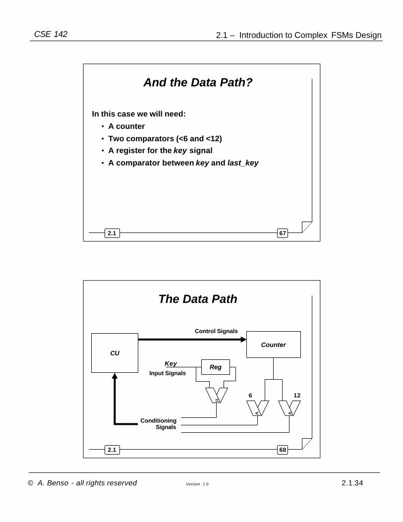
And the Data Path?
In this case we will need:
• A counter
• Two comparators (<6 and <12)• A register for the key signal
• A comparator between key and last_key
682.1
The Data Path
Counter
6 12
Control Signals
CU
ConditioningSignals
< <
RegInput Signals
Key
=
Page 35
© A. Benso - all rights reserved Version 1.0 2.1.35
2.1 – Introduction to Complex FSMs DesignCSE 142
692.1
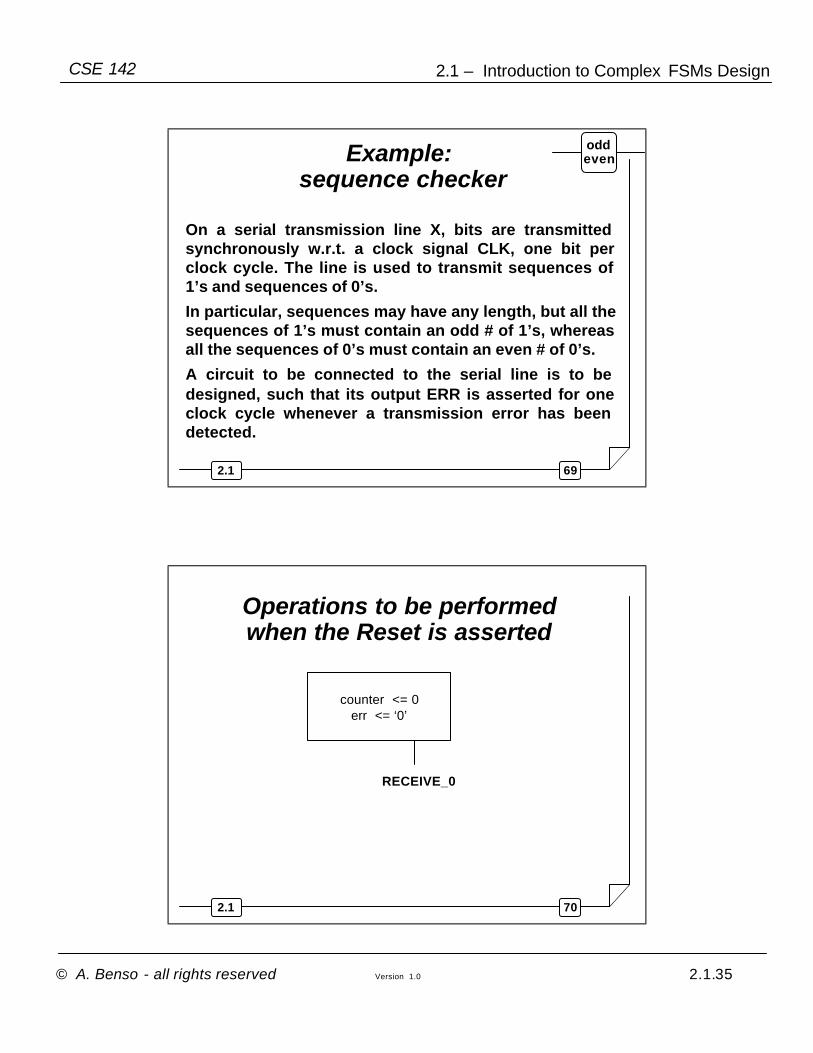
Example: sequence checker
On a serial transmission line X, bits are transmitted synchronously w.r.t. a clock signal CLK, one bit per clock cycle. The line is used to transmit sequences of 1’s and sequences of 0’s.
In particular, sequences may have any length, but all the sequences of 1’s must contain an odd # of 1’s, whereas all the sequences of 0’s must contain an even # of 0’s.
A circuit to be connected to the serial line is to be designed, such that its output ERR is asserted for one clock cycle whenever a transmission error has been detected.
oddeven
702.1
counter <= 0err <= ‘0’
RECEIVE_0
Operations to be performed when the Reset is asserted
Page 36
© A. Benso - all rights reserved Version 1.0 2.1.36
2.1 – Introduction to Complex FSMs DesignCSE 142
712.1
RECEIVE_0
If x=‘0’ else
If counter = ODD else
RECEIVE_1
counter <=1
err <=‘1’ err <=‘0’
counter <= ++
err <=‘0’
722.1
RECEIVE_0
RECEIVE_1
If x=‘0’ else
counter <=1
If counter = EVEN else
err <=‘1’ err <=‘0’
counter <= ++
err <=‘0’
Page 37
© A. Benso - all rights reserved Version 1.0 2.1.37
2.1 – Introduction to Complex FSMs DesignCSE 142
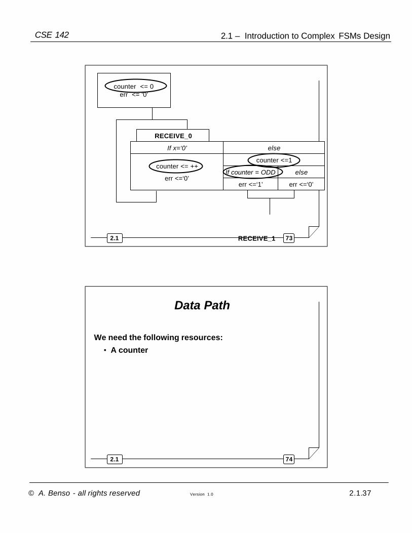
732.1
counter <= 0err <= ‘0’
RECEIVE_0
If x=‘0’ else
If counter = ODD else
RECEIVE_1
counter <=1
err <=‘1’ err <=‘0’
counter <= ++
err <=‘0’
742.1
Data Path
We need the following resources:
• A counter
Page 38
© A. Benso - all rights reserved Version 1.0 2.1.38
2.1 – Introduction to Complex FSMs DesignCSE 142
752.1
The Data Path
Counter
Control Signals
CU
ConditioningSignals
762.1
The Data Path
In this case the only conditioning signal I need is an even/odd signal that tells me if the value of the counter is even or odd.
It is a simple T or D Flip-Flop, enabled by the CU!