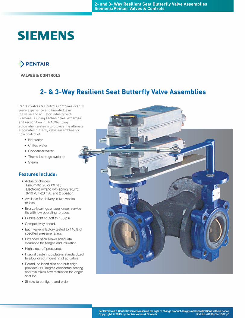
Pentair Valves & Controls combines over 50years experience and knowledge in the valve and actuator industry withSiemens Building Technologies’ expertiseand recognition in HVAC/buildingautomation systems to provide the ultimateautomated butterfly valve assemblies forflow control of:
Features and Benefits• Molded-in resilient seat provides bubble-tight shutoff to 250 psi.
• Offered in two body styles: wafer and lug.The lugged body is drilled and tapped forisolation and removal of downstreampiping at full rated pressure.
• Round, polished disc and hub edgeprovides 360 degree concentric seating,minimum flow restriction, lower torquesand longer seat life.
• Upper and lower inboard bronze bearingsensure longer service life with lowoperating torques.
• Thru-stem design provides high strengthand positive disc control with standardizedend connection for operatorinterchangeability.
• Extended neck allows adequate clearancefor flanges and insulation.
• Bi-directional, self-adjusting stem seal,located in the upper journal, is suitable forvacuum and pressure while also preventingexternal contamination of the stem area.
• Heavy-duty corrosion resistant topbushing, located in the upper journal,absorbs actuator side thrust.
• Cast-in top plate is an integral part of thebody and is standardized to allow directmounting of all Keystone actuators.
• Each valve is factory tested to 110 percentof specified pressure rating.
• Temperature rating for standard EPDM: -40°F -250°F.
• Flange standard is ANSI 125/150
Keystone Figure 222 and Figure AR2 Resilient Seat Butterfly Valves
Materials - Figure 222Part Material Material Standards1 Body Cast iron ASTM-A 126 Class B2 Disc 304 Stainless steel ASTM-A 148 UNS C95200 Grade A3 Stem 416 Stainless steel ASTM-A 582 UNS S416004 Molded-in liner EPDM (-40°F – 250°F)5 Inboard bearings Bronze6 Upper bushing Polyester7 Upper stem seal NBR
Materials - Figure AR2Part Material Material Standards1 Body Cast iron ASTM-A 126 Class B2 Disc Aluminum bronze ASTM B 148, UNS C95200 Grade A3 Stem 316 Stainless steel ASTM A 276 UNS S31600
18-8 Stainless steel (14 – 20-inch) ASTM A 276 UNS S304004 Seat EPDM food grade (-40°F – 250°F)5 Upper stem bushing Polyester (2 – 20-inch)6 Stem packing NBR7 Torque plug (2 – 12-inch) 316 Stainless steel ASTM A 276 UNS S31600 cond. A
Disc screws (14 – 20-inch) 316 Stainless steel ASTM F 593 Group 2 cond. CW18 Bearings (2 – 12-inch) Sintered metal
Standard• Standard actuator accepts 100 to 240 VoltDC or AC single phase input, 50 and 60 Hz. Three phase is optional.
• Separate terminal enclosure isolated fromthe electronics and motor compartment.Only the wiring terminal is exposed duringfield installation.
• Standard adjustable torque switches, from40 to 100% of rated torque output.
• Manual override does not require a de-clutchable mechanism - alwaysengaged.
• NEMA 4 / 4X / 6 UL and CSA enclosures.Optional Explosion Proof FM and CSAenclosures.
• Anodized aluminum with epoxy powdercoat to protect unit in most aggressiveenvironments.
• Visual mechanical position indicator foraccurate visual reference of valve position.
• Direct mounting to Keystone valves orreadily adaptable to other quarter-turnvalves; minimizes costs associated withadaptation.
• Permanently lubricated self-locking geartrain eliminates the need for motor brakes.
• Mechanical travel stops prevent over-travelduring hand wheel or motor operation.
• Over temperature Motor thermostat.• Integral speed control independentlyadjustable in open and closing directions.
Optional• Analog control modules offer 4 to 20 mAinput/output. Complete with additionaloutput relays and monitor relay. Alternate 0 to 10 VDC input/output.
• Communication Modules for moststandard communication bus protocols.Bluetooth™ modules allow for non-intrusive access to the EPI2 forconfiguration, operation and interrogationvia a Bluetooth™ enabled handheld PDAor PC.
General applicationsQuarter-turn ball, butterfly, or rotary plugvalves, dampers, etc.
Technical dataTemperature: Units available for
-40°F to 158°F[-40°C to 70°C]
Output torque: up to 17,700 lb. in.[2000 Nm]
Voltage: Standard Unit: Universal for - 100 to 240 VAC, 1 phase 60/50hertz
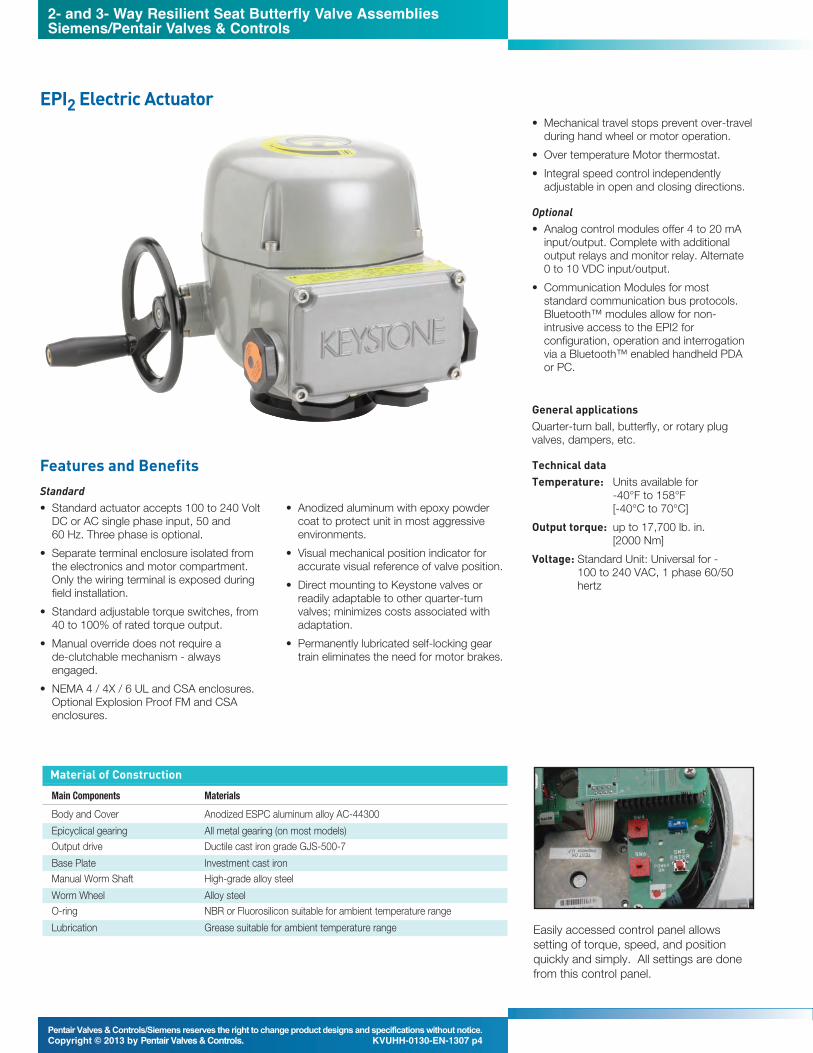
EPI2 Electric Actuator
Easily accessed control panel allowssetting of torque, speed, and positionquickly and simply. All settings are donefrom this control panel.
Material of ConstructionMain Components MaterialsBody and Cover Anodized ESPC aluminum alloy AC-44300Epicyclical gearing All metal gearing (on most models)Output drive Ductile cast iron grade GJS-500-7Base Plate Investment cast ironManual Worm Shaft High-grade alloy steelWorm Wheel Alloy steelO-ring NBR or Fluorosilicon suitable for ambient temperature rangeLubrication Grease suitable for ambient temperature range
Features and Benefits
2- and 3- Way Resilient Seat Butterfly Valve AssembliesSiemens/Pentair Valves & Controls
EPI2 Basic Unit Technical DetailVoltage Ratings100 to 240 Volts DC or AC single phase50/60 Hz. +/- 10% voltage tolerances; +/- 5% Frequency.
Working TemperatureStandard Range: -40°F to 140°F
[-40°C to 60°C]Optional Ranges Covering From:
-40°F to 158°F [-40°C to 70°C]
Environmental ProtectionStandard Weather Tight EnclosureNEMA 4/4X/6 according to NEMA ICS6/NEMA 250IP68 according to EN 60529Standard unit is UR (UL Recognized per UL873/XAPX2)
Optional Explosion Proof EnclosureFM/CSA NEC 505 (Class 1, Zone 1 & 2)NEC 500 (Class 1, Div. 2)
Electric motor and universal power supplyInnovative POWER SUPPLY MODULE™ toaccept 100 V to 240 V DC and AC 1-phase input voltages at 50 and 60 Hz provides flexibility for a broadrange of applications.Over temperature device to protect themotor and electronics is included.
Local IndicatorStandard "Window" type located in thecover.
Travel StopsMechanical stops on the base of theactuator provide +/- 10° over/under travelin each direction (70° minimum to 110°maximum angular stroke).
Anti-condensation HeaterStandard with 10 Watt thermostat willactivate the heater when the ambienttemperature drops below +59°F.
Terminal EnclosureTerminal board is in a separatecompartment.Removal of the actuator’s control cover to do field wiring is no longer required.Four 1” NPT conduit openings allow flexibilityin wiring access.
Electronic Controls“Push-to-Run” 3 wire(Open/Close/Common) remote controlsignals.Torque sensing in both directions of travel,adjustable in 10 steps from 40% to 100% of the actuator’s rated torque output.Absolute encoder is used for positionfeedback.Output speed adjustment with ratio of 1 to 9; Speed independently adjustablefor the opening and closing directions.Four SPST (NO/NC) latching contacts areprovided for fully Open/ fully Closed remoteindication. Contact ratings are 5 Amp at120 VAC and 5 Amp at 30 VDC.
Base Unit Default SettingsThe actuators are provided with thefollowing default values:- Closing limit by Position- Opening limit by Position- Stroking time for closing and opening; 15 seconds for models E006, E013,E025, and E051, 30 seconds for theE091, and 66 seconds for the E171.- Torque Limiting for closing and openingset at 100% of nominal torque.
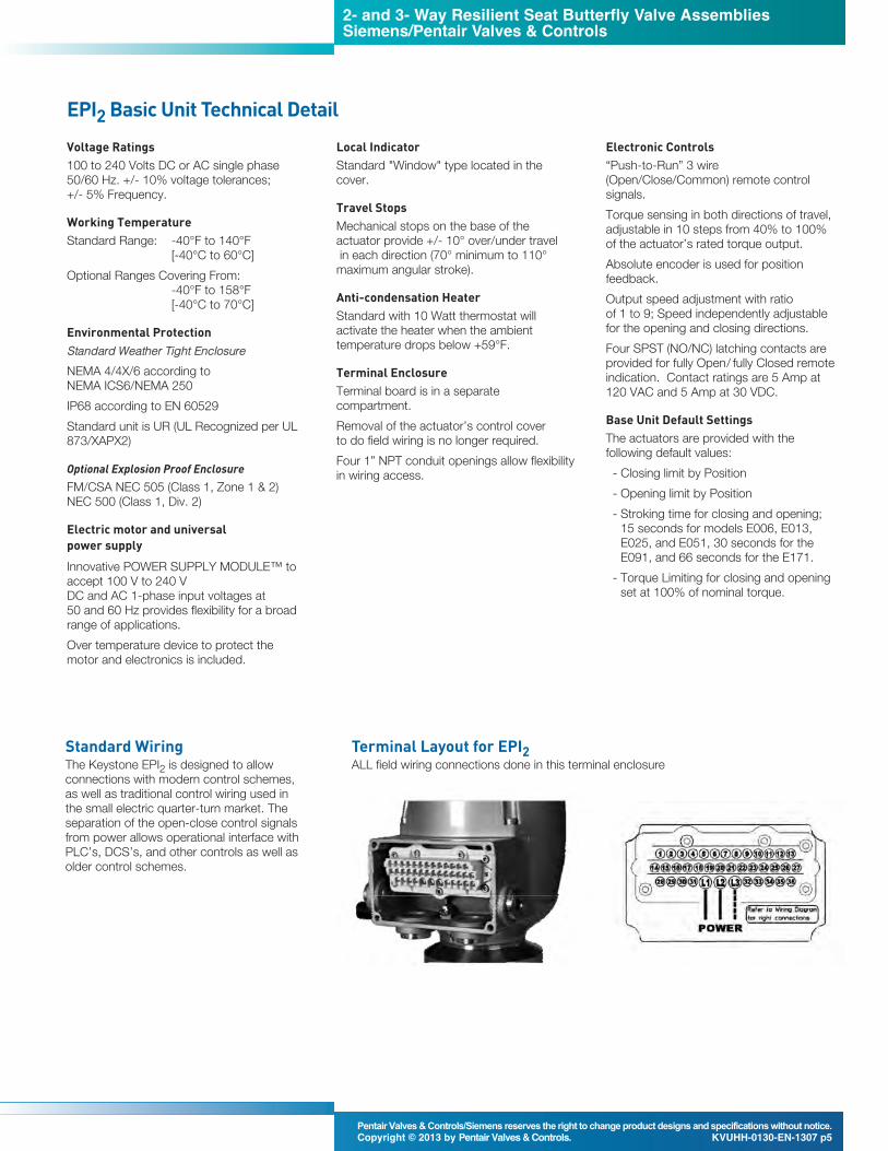
Terminal Layout for EPI2ALL field wiring connections done in this terminal enclosure
Standard WiringThe Keystone EPI2 is designed to allowconnections with modern control schemes,as well as traditional control wiring used inthe small electric quarter-turn market. Theseparation of the open-close control signalsfrom power allows operational interface withPLC’s, DCS’s, and other controls as well asolder control schemes.
2- and 3- Way Resilient Seat Butterfly Valve AssembliesSiemens/Pentair Valves & Controls
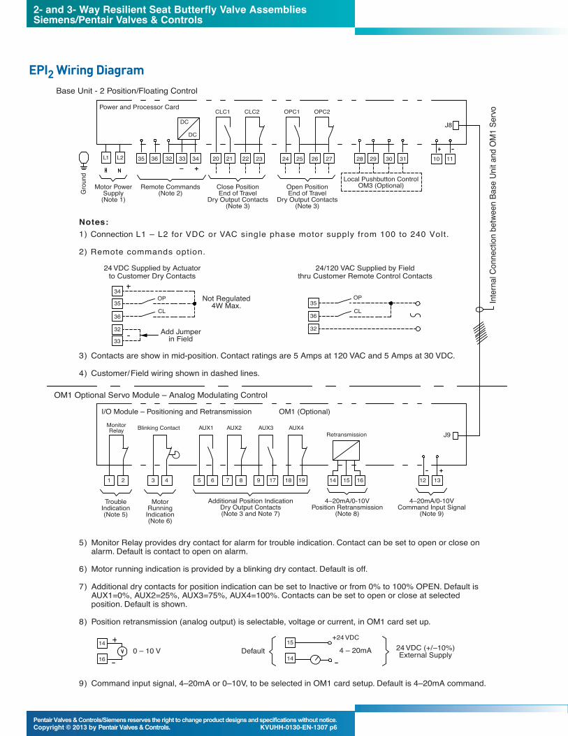
Monitor Relay provides dry contact for alarm for trouble indication. Contact can be set to open or close onalarm. Default is contact to open on alarm.
Motor running indication is provided by a blinking dry contact. Default is off.
Additional dry contacts for position indication can be set to Inactive or from 0% to 100% OPEN. Default isAUX1=0%, AUX2=25%, AUX3=75%, AUX4=100%. Contacts can be set to open or close at selectedposition. Default is shown.
Position retransmission (analog output) is selectable, voltage or current, in OM1 card set up.
Command input signal, 4–20mA or 0–10V, to be selected in OM1 card setup. Default is 4–20mA command.
L1 L2
DC
DC
35 36 32 33 34– +
20 21 22 23
CLC1 CLC2 OPC1 OPC2
24 25 26 27 28 29 30 31
Local Pushbutton ControlOM3 (Optional)
10 11
J8
Grou
nd
Motor PowerSupply
(Note 1)Remote Commands
(Note 2)Close PositionEnd of Travel
Dry Output Contacts(Note 3)
Open PositionEnd of Travel
Dry Output Contacts(Note 3)
Power and Processor Card
Base Unit - 2 Position/Floating Control
5)
6)
7)
8)
9)
Inter
nal C
onne
ction
betw
een B
ase U
nit an
d OM1
Ser
vo
Connection L1 – L2 for VDC or VAC single phase motor supply from 100 to 240 Volt.
Remote commands option.
Contacts are show in mid-position. Contact ratings are 5 Amps at 120 VAC and 5 Amps at 30 VDC.
Customer/Field wiring shown in dashed lines.
1)
2)
Notes:
3)
4)
32
33
36
35
34
24 VDC Supplied by Actuatorto Customer Dry Contacts
Not Regulated4W Max.
Add Jumperin Field
OP
CL
24/120 VAC Supplied by Fieldthru Customer Remote Control Contacts
OP
CL
32
36
35
OM1 Optional Servo Module – Analog Modulating Control
TroubleIndication(Note 5)
MotorRunning
Indication(Note 6)
Additional Position IndicationDry Output Contacts(Note 3 and Note 7)
Features and Benefits• Self-centering shaft coupling• Rugged all metal housing, rated NEMA 2• Accepts shaft diameters up to 1” [25 mm]• Available input signals-0 to 10 Vdc-4 to 20 mA
• 3-position (floating) control• Quiet,low-power operation• Brushless DC motor technology with stallprotection
• Assembled in USA• Manual overrideGCA onlyThe GCA Series spring return actuators aredesigned to return to a fail-safe position whenthere is a power failure.• Bi-directional fail-safe spring return• 2-position (on off) control
2- and 3- Way Resilient Seat Butterfly Valve AssembliesSiemens/Pentair Valves & Controls
Features and Benefits• Compact rack and pinion design utilizesthe whole piston area to develop outputtorque.
• Pistons with integral rack drive reduce thenumber of dynamic seals, minimizing airleakage.
• Double pistons nullify sideloads on thepinion shaft, minimizing bearing wear andextending life.
• Internal air porting eliminates externaltubing.
• Hard anodized aluminum body withexternal electrostatic powder coating(ESPC) finish protects against corrosiveenvironments.
• Female output drive enables directmounting of most Keystone valves,eliminating special adaptation connectionsand assuring correct alignment.
• Bottom entry pinion shaft simplifiesassembly and provides anti-blowoutfeature.
• Anti-friction piston pads ensure no metal-to-metal contact, providing smoothoperation. Ideal for modulating or on/offcontrol applications.
• Adjustable travel stops standard in bothdirections on models 065S, 090S and180S.
Materials of ConstructionItem Material US Material Standard UK Material Standard DIN Material Standard1 Body Extruded aluminum ASTM B221 BS1474 6063 DIN 3.33206.51
(hard anodized & ESPC*)2 Spring housing Die-cast aluminum ASTM B85 BS1490 DIN 1725 - 230 or 226
2- and 3- Way Resilient Seat Butterfly Valve AssembliesSiemens/Pentair Valves & Controls
Specifications
Model: 331-2792Effective Diaphragm ............................................ 17.9 in.•[115 cm •]Stroke .............................................................................. 4” [102 mm]Max. Air Pressure .................................................. 30 psig (207 kPa)Ambient Temperature Range
Operating ........................................ -20 to +160°F [-29 to +71°C]Storage ............................................ -20 to +160°F [-29 to +71°C]
Air Connection ............................................................ 1/8” NPT femaleType of Mounting ........................................................................ PivotShipping Weight (Actuator only) ................................ 9.0 lb. (4.08 kg)
Model: MP920Effective Diaphragm.............................................. 24.8 in.•[160 cm •]Stroke .............................................................................. 6” [150 mm]Max. Air Pressure .................................................... 29 psig [200 kPa]Ambient Temperature Range
Operating.......................................... -20 to +160°F [-29 to +71°C]Storage ............................................ -20 to +160°F [-29 to +71°C]
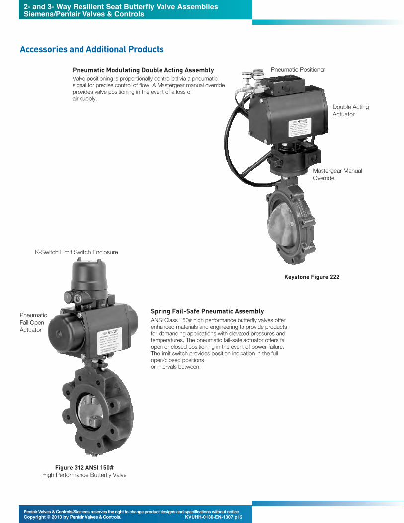
Pneumatic Modulating Double Acting AssemblyValve positioning is proportionally controlled via a pneumaticsignal for precise control of flow. A Mastergear manual overrideprovides valve positioning in the event of a loss of air supply.
Spring Fail-Safe Pneumatic AssemblyANSI Class 150# high performance butterfly valves offerenhanced materials and engineering to provide productsfor demanding applications with elevated pressures andtemperatures. The pneumatic fail-safe actuator offers failopen or closed positioning in the event of power failure.The limit switch provides position indication in the fullopen/closed positions or intervals between.
Keystone Figure 222
Double ActingActuator
Pneumatic Positioner
K-Switch Limit Switch Enclosure
Figure 312 ANSI 150# High Performance Butterfly Valve
Mastergear ManualOverride
2- and 3- Way Resilient Seat Butterfly Valve AssembliesSiemens/Pentair Valves & Controls
Dimensions, inches [mm]Valve Valve A B C D E F G H J L M Actuator NotesModel Size Valve Body CL Pipe to Face/Face Tap Size Bolt No. Actuator Actuator CL Stroke Model
Dimensions, inches [mm] Valve Valve A B C D E F G H J L M N P Actuator NotesModel Size Valve Body CL Pipe to Face/Face Tap Size Bolt No. Actuator Actuator CL Stroke Tee Run Model
Height O.D. Top Plate Circle Bolts Height Width Length Clearance Width Length
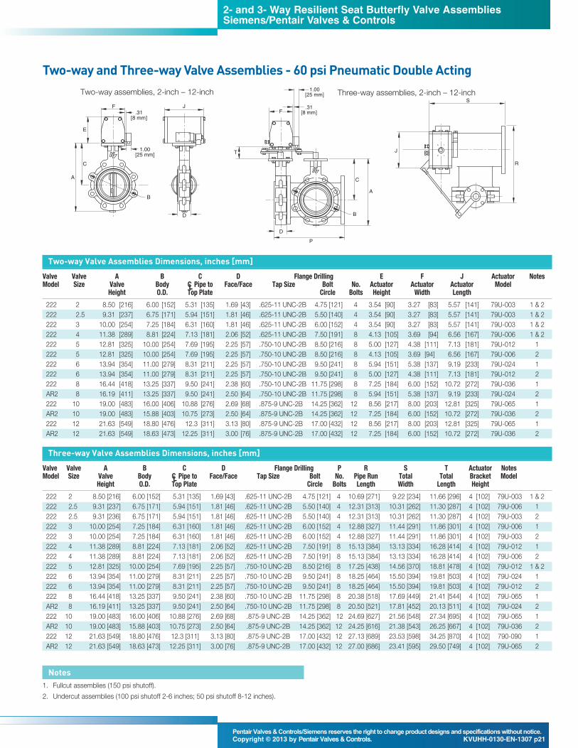
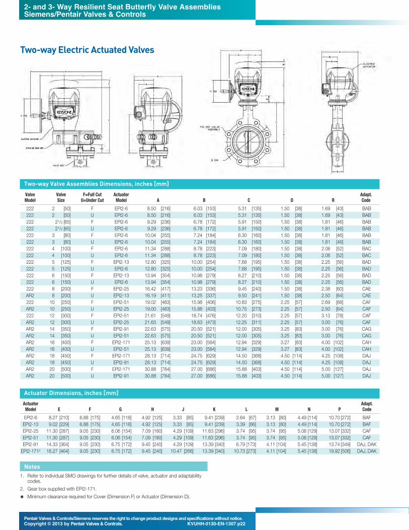
Two-way Valve Assemblies Dimensions, inches [mm] ValveValve A B C D Flange Drilling E F K Actuator NotesModel Size Valve Body CL Pipe to Face/Face Tap Size Bolt No. Actuator Actuator CL Model
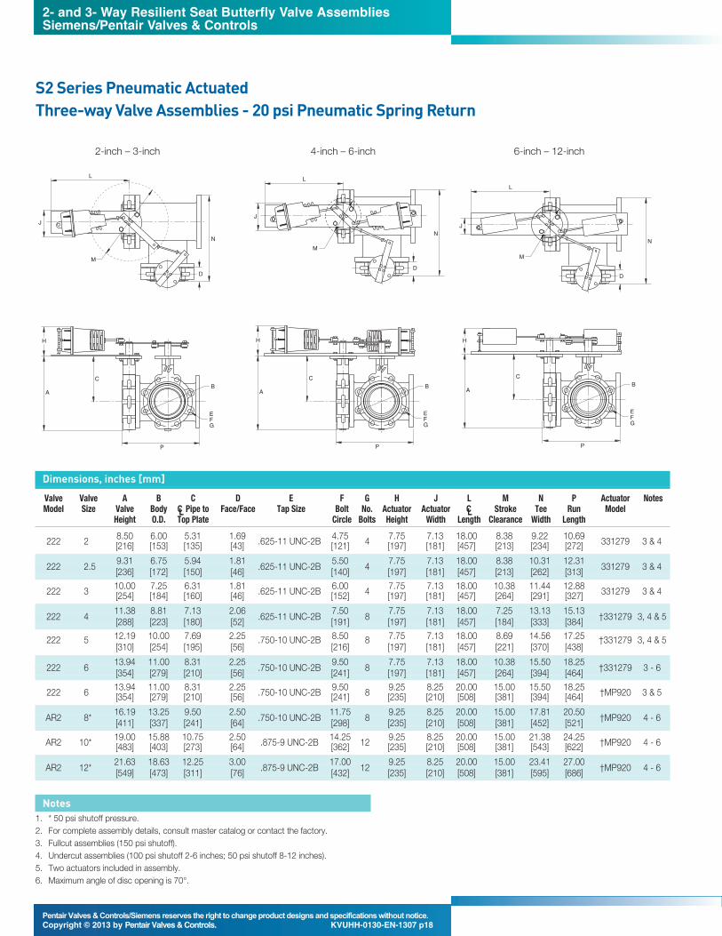
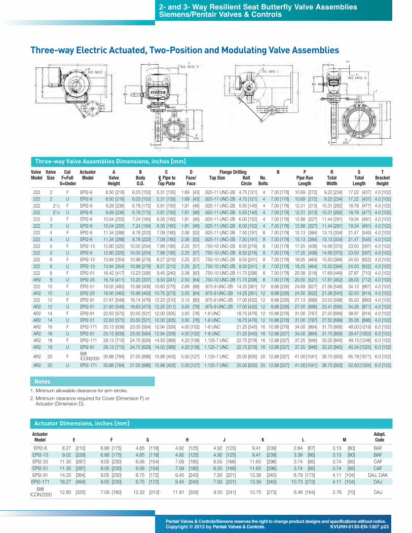
Three-way Valve Assemblies Dimensions, inches [mm] Valve Valve A B C D Flange Drilling P R S T Actuator NotesModel Size Valve Body CL Pipe to Face/Face Tap Size Bolt No. Pipe Run Total Total Bracket Model
Three-way Valve Assemblies Dimensions, inches [mm] Valve Valve A B C D Flange Drilling P R S T Actuator NotesModel Size Valve Body CL Pipe to Face/Face Tap Size Bolt No. Pipe Run Total Total Bracket Model
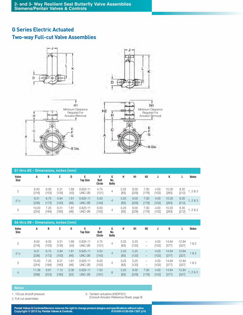
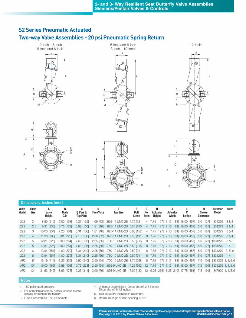
Two-way Valve Assemblies Dimensions, inches [mm] Valve Valve A B C D Flange Drilling E F J Actuator NotesModel Size Valve Body CL Pipe to Face/Face Tap Size Bolt No. Actuator Actuator Actuator Model
Three-way Electric Actuated, Two-Position and Modulating Valve Assemblies
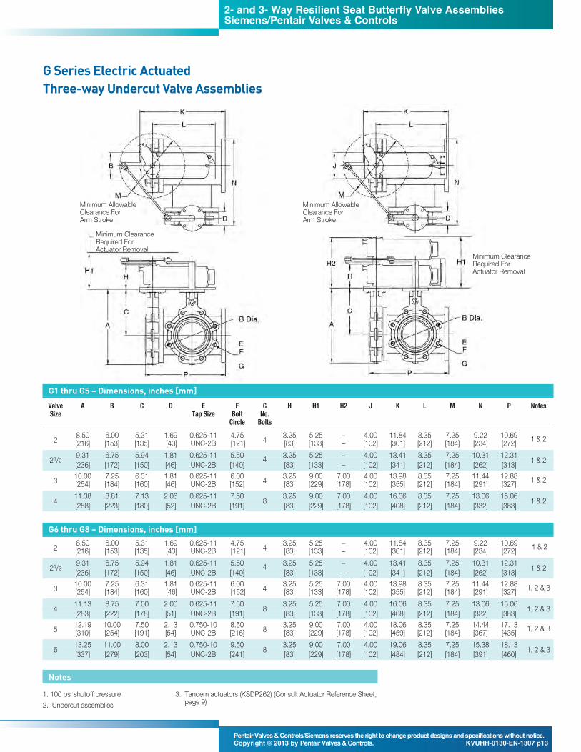
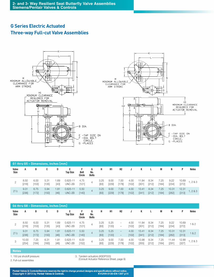
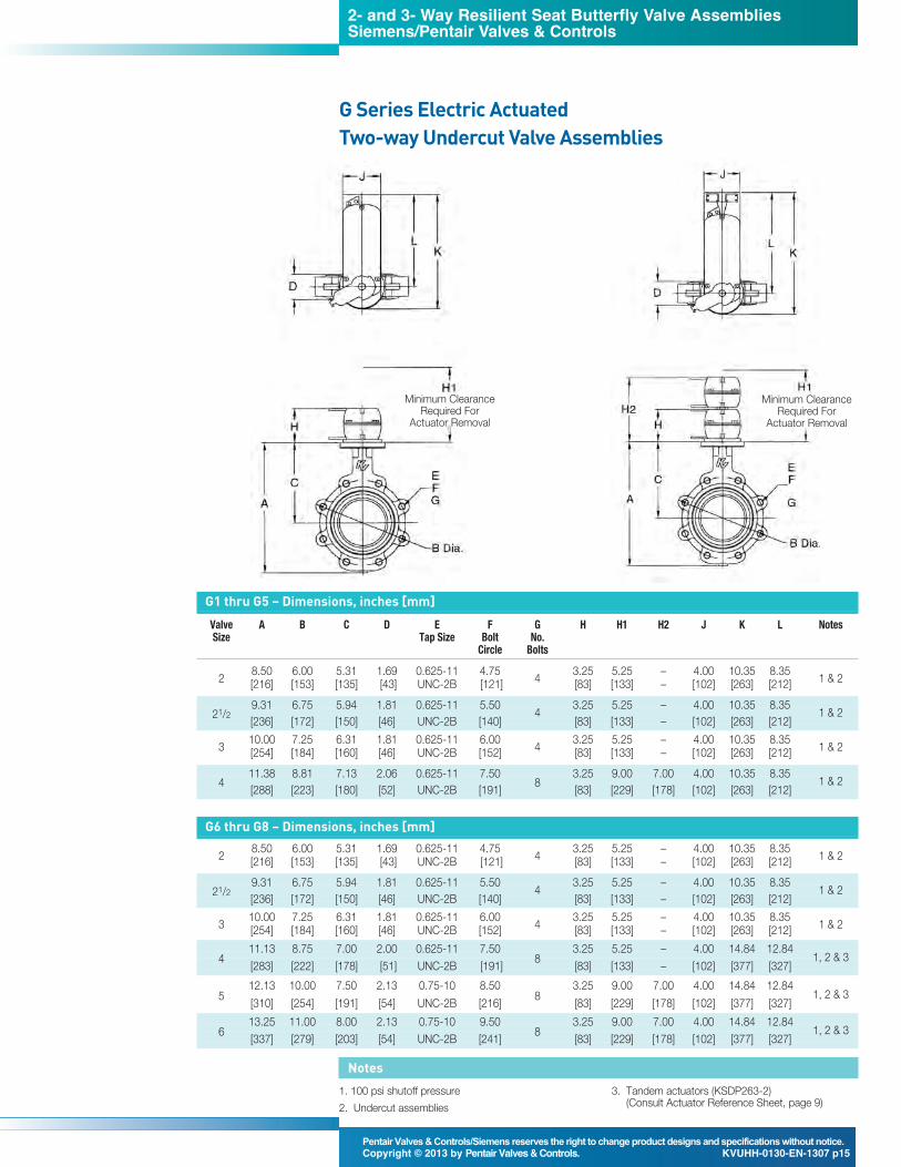
Notes1. Minimum allowable clearance for arm stroke. 2. Minimum clearance required for Cover (Dimension F) orActuator (Dimension D).
Three-way Valve Assemblies Dimensions, inches [mm]Valve Valve Cut Actuator A B C D Flange Drilling N P R S TModel Size F=Full Model Valve Body CL Pipe to Face/ Tap Size Bolt No. Pipe Run Total Total Bracket
(based on max. tee flow, run = 90° and branch = 0°)
6-inch 222/AR2 at Constant Valve Differential Pressure (corrected for tee loss)
Mixing
Branch Leg
Run Leg
Notes1. Three-way valve assemblies Cv’s are correctedfrom published two-way Cv’s to account for line
losses generated by the tee, and are calculatedvalues only. The pipe friction losses are afunction of fluid velocity through the pipe and thethree-way Cv’s listed are apparent for full flowthrough the pipe. Operation at less than fullcapacity (lower velocity) will increase the actualCv’s.
2. The chart is based on percentages and willreflect any valves Cv’s when two butterfly valvesare installed on a tee. This includes all Keystone Valves and all other manufacturer’svalves. The percentages are only a reflection ofthe tee losses.
Position 9 8 7 6 5 4 3 2 1 0Output torque is independently adjustable from 40% to 100% in both directions of travel. Adjustments are in increments of 1 from 0 to 9. The default setting is 100%, position9 on the rotary selector used for configuration.
Position 9 8 7 6 5 4 3 2 1 0Output speed is adjustable from 10% to 100% in both directions of travel. Adjustments are in increments of 1 from 0 to 9. The default settings are: 15 seconds for the E006,E013, E025 & E051 - 30 seconds for the E091 - and 66 seconds for the E171. The tolerance is +/- 10% of nominal.
PerformanceAdjustable torque and stroke time offers flexibility in performance and valve protection unsurpassed in the small electric quarter-turn market.
2- and 3- Way Resilient Seat Butterfly Valve AssembliesSiemens/Pentair Valves & Controls
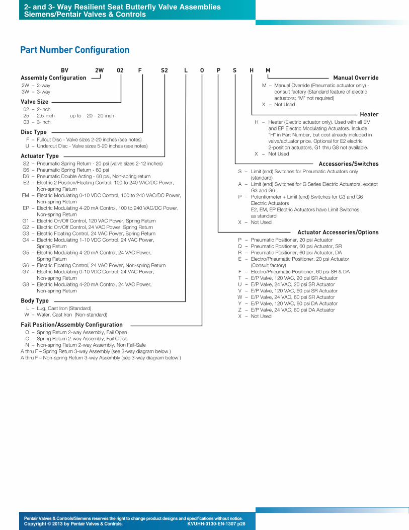
Actuator TypeS2 – Pneumatic Spring Return - 20 psi (valve sizes 2-12 inches)S6 – Pneumatic Spring Return - 60 psiD6 – Pneumatic Double Acting - 60 psi, Non-spring returnE2 – Electric 2 Position/Floating Control, 100 to 240 VAC/DC Power,
Non-spring ReturnEM – Electric Modulating 0-10 VDC Control, 100 to 240 VAC/DC Power,
Non-spring ReturnEP – Electric Modulating 4-20 mA Control, 100 to 240 VAC/DC Power,
Non-spring ReturnG1 – Electric On/Off Control, 120 VAC Power, Spring ReturnG2 – Electric On/Off Control, 24 VAC Power, Spring ReturnG3 – Electric Floating Control, 24 VAC Power, Spring ReturnG4 – Electric Modulating 1-10 VDC Control, 24 VAC Power,
Spring ReturnG5 – Electric Modulating 4-20 mA Control, 24 VAC Power,
Spring ReturnG6 – Electric Floating Control, 24 VAC Power, Non-spring ReturnG7 – Electric Modulating 0-10 VDC Control, 24 VAC Power,
Non-spring ReturnG8 – Electric Modulating 4-20 mA Control, 24 VAC Power,
Non-spring Return
Body TypeL – Lug, Cast Iron (Standard)W – Wafer, Cast Iron (Non-standard)
Fail Position/Assembly ConfigurationO – Spring Return 2-way Assembly, Fail OpenC – Spring Return 2-way Assembly, Fail Close N – Non-spring Return 2-way Assembly, Non Fail-Safe
A thru F – Spring Return 3-way Assembly (see 3-way diagram below )A thru F – Non-spring Return 3-way Assembly (see 3-way diagram below )
consult factory (Standard feature of electricactuators; “M” not required)
X – Not Used
HeaterH – Heater (Electric actuator only). Used with all EM
and EP Electric Modulating Actuators. Include “H” in Part Number, but cost already included invalve/actuator price. Optional for E2 electric 2-position actuators, G1 thru G8 not available.
X – Not Used
Accessories/SwitchesS – Limit (end) Switches for Pneumatic Actuators only
(standard)A – Limit (end) Switches for G Series Electric Actuators, except
G3 and G6 P – Potentiometer + Limit (end) Switches for G3 and G6
Electric Actuators E2, EM, EP Electric Actuators have Limit Switches as standard
(Consult factory)F – Electro/Pneumatic Positioner, 60 psi SR & DA T – E/P Valve, 120 VAC, 20 psi SR Actuator U – E/P Valve, 24 VAC, 20 psi SR Actuator V – E/P Valve, 120 VAC, 60 psi SR Actuator W – E/P Valve, 24 VAC, 60 psi SR Actuator Y – E/P Valve, 120 VAC, 60 psi DA ActuatorZ – E/P Valve, 24 VAC, 60 psi DA Actuator X – Not Used
BV 2W 02 F S2 L O P S H M
2- and 3- Way Resilient Seat Butterfly Valve AssembliesSiemens/Pentair Valves & Controls
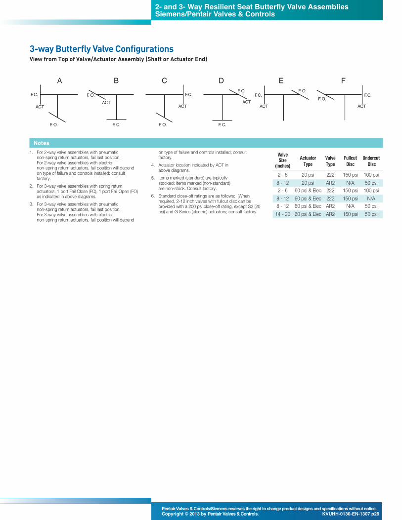
1. For 2-way valve assemblies with pneumatic non-spring return actuators, fail last position. For 2-way valve assemblies with electric non-spring return actuators, fail position will dependon type of failure and controls installed; consultfactory.
2. For 3-way valve assemblies with spring returnactuators, 1 port Fail Close (FC), 1 port Fail Open (FO)as indicated in above diagrams.
3. For 3-way valve assemblies with pneumatic non-spring return actuators, fail last position. For 3-way valve assemblies with electric non-spring return actuators, fail position will depend
on type of failure and controls installed; consultfactory.
4. Actuator location indicated by ACT in above diagrams.
5. Items marked (standard) are typically stocked; items marked (non-standard) are non-stock. Consult factory.
6. Standard close-off ratings are as follows: (Whenrequired, 2-12 inch valves with fullcut disc can beprovided with a 200 psi close-off rating, except S2 (20psi) and G Series (electric) actuators; consult factory.
Notes
3-way Butterfly Valve ConfigurationsView from Top of Valve/Actuator Assembly (Shaft or Actuator End)
The data presented in this bulletin is for general information only. Manufacturer is not responsible for acceptability of these products in relation to systemrequirements. Patents and Patents Pending in U.S. and foreign countries. All rights reserved. Printed in U.S.A. Pentair/Siemens, reserves the right to change productdesigns and specifications without notice.