Remote Controller (Wireless Type) O H 0 8 -1 86 C o n tro l S y s te m s 2 .5 B RC4 C6 5 / B RC4 C6 6 (for F X M Q -P ) 2 .5 .1 F ea tu res B RC4 C6 5 (for H ea t P u mp) B RC4 C6 6 (for Cooling O nly) T he sam e operation m odes and settings as w ith w ire d re m o te c o n tro lle rs a re p o s s ib le . A com p a c t a n d lig h t s ig n a l re c e iv e r u n it to b e m ounted into a w a ll o r c e ilin g is in c lu d e d . T h is u n it s u p p o rts th e th re e -s p e e d a irflo w ra te c o n tro l (H H / H / L ). 2 .5 .2 F u nc tion S ig n a l re c e iv e r u n it M odel B R C 4 C 65 /66 ON/OFF P o s s ib le T em p . s e ttin g P o s s ib le A ir flo w ra te s e ttin g P o s s ib le A ir flo w d ire c tio n s e ttin g P o s s ib le T im e r s e ttin g P o s s ib le M o d e s e ttin g P o s s ib le F ilte r s ig n re s e t P o s s ib le In s p e c tio n /T e s t o p e ra tio n P o s s ib le (N o s u p p o rt fo r s w ing m ode)
Transcript
Remote Controller (Wireless Type) O H 0 8 -1
86 C o n tro l S y s te m s
2 .5 B RC4 C6 5 / B RC4 C6 6 (for F X M Q -P )
2 .5 .1 F ea tu res
B RC4 C6 5 (for H ea t P u mp)
B RC4 C6 6 (for Cooling O nly)
T h e s a m e o p e ra tio n m o d e s a n d s e ttin g s a s w ith w ire d re m o te c o n tro lle rs a re p o s s ib le .
A c o m p a c t a n d lig h t s ig n a l re c e iv e r u n it to b e m o u n te d in to a w a ll o r c e ilin g is in c lu d e d .
T h is u n it s u p p o rts th e th re e -s p e e d a irflo w ra te c o n tro l (H H / H / L ).
2 .5 .2 F u nc tion
S ig n a l re c e iv e r u n it
M o d e l B R C 4 C 65 /66
O N /O F F P o s s ib le
T e m p . s e ttin g P o s s ib le
A ir flo w ra te s e ttin g P o s s ib le
A ir flo w d ire c tio n s e ttin g P o s s ib le
T im e r s e ttin g P o s s ib le
M o d e s e ttin g P o s s ib le
F ilte r s ig n re s e t P o s s ib le
In s p e c tio n /T e s t o p e ra tio n P o s s ib le
(N o s u p p o rt fo r s w in g m o d e )
OH08-1 Remote Controller (Wireless Type)
Control Systems 87
2
2.5.3 D imensions
• RE CE IV E R D E TAIL
(Ceiling Opening)
TRANSMITTING PART
• RE MOTE CONTROLLE R D IME NSIONS
(Ceili
ng O
penin
g)
• RE MOTE CONTROLLE R HOLD E R INSTALLATION PROCE D U RE < INSTALLATION TO W ALL SU RFACE >
Switch box
(Field Supplied parts)
• Service space for ceiling installation(S
ervi
ce s
pace
)
D o not install more than 3 receivers in the vicinity ofone another.W ith 4 or more units, there is always the possibilityof malfunction.
NOTE
mor
e th
an 9
0
0 .57 0
1 7 .5
157
106
72
49
62
83.5
LIQ U ID CRY STALRE MOTE CONTROLLE R(W IRE LE SS)
RE MOTE CONTROLLE RHOLD E R
120
3 51 8
2 -5 × 9 Slot
P1 P2
3 D 0 0 7 89 8B
2.5
BR
C4C
65 / B
RC
4C
66
Remote Controller (Wireless Type) OH08-1
88 Control Systems
2.5.4 Operation Manual
N ames and Functions of th e Operating S ection
1-1
1-2
7
9
12
10
11
13
14
15
8
1
3
4
5
2
6
DOWN
FAN
UP
ON OFF
MH L
C
hr.
hr.
TESTMODE
TIMER
RESERVE CANCEL
DOWN
UP
TEST
FAN
TIMETEMP
ON OFF
MH L
C
hr.
hr.
TEST
1
1-3 2
COOL /HE A T CHA N G E OV E R
RE MOTE CON TROL S WITCH
23
22
18
19
21
20
16
17
OH08-1 Remote Controller (Wireless Type)
Control Systems 89
2
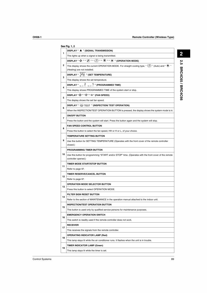
See Fig. 1, 2
1DISPLAY “ ” (SIGNAL TRANSMISSION)
This lights up when a signal is being transmitted.
2
DISPLAY “ ” “ ” “ ” “ ” “ ” (OPERATION MODE)
This display shows the current OPERATION MODE. For straight cooling type, “ ” (Auto) and “ ”
(Heating) are not installed.
3DISPLAY “ ” (SET TEMPERATU RE)
This display shows the set temperature.
4DISPLAY “ ” (PROGRAMMED TIME)
This display shows PROGRAMMED TIME of the system start or stop.
5DISPLAY “ ” “ ” “ ” (FAN SPEED)
The display shows the set fan speed.
6DISPLAY “ ” (INSPECTION/ TEST OPERATION)
When the INSPECTION/TEST OPERATION BUTTON is pressed, the display shows the system mode is in.
7ON/OFF BU TTON
Press the button and the system will start. Press the button again and the system will stop.
8FAN SPEED CONTROL BU TTON
Press this button to select the fan speed, HH or H or L, of your choice.
9
TEMPERATU RE SETTING BU TTON
Use this button for SETTING TEMPERATURE (Operates with the front cover of the remote controller
closed.)
10
PROGRAMMING TIMER BU TTON
Use this button for programming “START and/or STOP” time. (Operates with the front cover of the remote
controller opened.)
11TIMER MODE START/STOP BU TTON
Refer to page 97.
12TIMER RESERVE/CANCEL BU TTON
Refer to page 97.
13OPERATION MODE SELECTOR BU TTON
Press this button to select OPERATION MODE.
14FILTER SIGN RESET BU TTON
Refer to the section of MAINTENANCE in the operation manual attached to the indoor unit.
15INSPECTION/TEST OPERATION BU TTON
This button is used only by q ualified service persons for maintenance purposes.
16EMERGENCY OPERATION SWITCH
This switch is readily used if the remote controller does not work .
17RECEIVER
This receives the signals from the remote controller.
18OPERATING INDICATOR LAMP (Red)
This lamp stays lit while the air conditioner runs. It flashes when the unit is in trouble.
19TIMER INDICATOR LAMP (Green)
This lamp stays lit while the timer is set.
MH L
C
hr. hr.
TEST
2.5
BR
C4C
65 / B
RC
4C
66
Remote Controller (Wireless Type) OH08-1
90 Control Systems
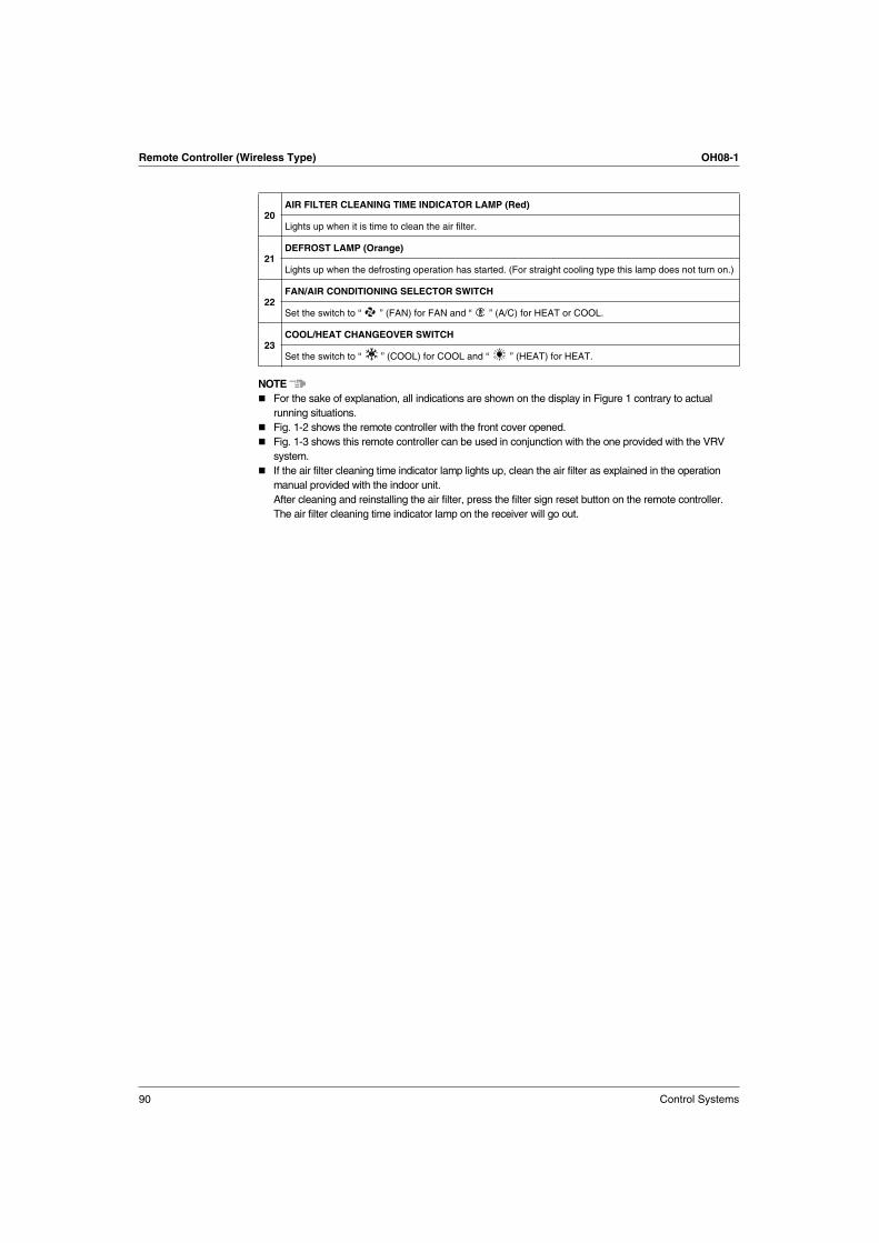
NOTE
For the sake of explanation, all indications are shown on the display in Figure 1 contrary to actual
running situations.
Fig. 1-2 shows the remote controller with the front cover opened.
Fig. 1-3 shows this remote controller can be used in conjunction with the one provided with the VRV
system.
If the air filter cleaning time indicator lamp lights up, clean the air filter as explained in the operation
manual provided with the indoor unit.
After cleaning and reinstalling the air filter, press the filter sign reset button on the remote controller.
The air filter cleaning time indicator lamp on the receiver will go out.
20AIR FILTER CLEANING TIME INDICATOR LAMP (Red)
Lights up when it is time to clean the air filter.
21DEFROST LAMP (Orange)
Lights up when the defrosting operation has started. (For straight cooling type this lamp does not turn on.)
22FAN/AIR CONDITIONING SELECTOR SWITCH
Set the switch to “ ” (FAN) for FAN and “ ” (A/C) for HEAT or COOL.
23COOL/HEAT CHANGEOVER SWITCH
Set the switch to “ ” (COOL) for COOL and “ ” (HEAT) for HEAT.
OH08-1 Remote Controller (Wireless Type)
Control Systems 91
2
3
4
MODE
TIMER
RESERVE CANCEL
DOWN
UP
/TEST
FAN
TIMETEMP
2 5
4
1
ON OFF
C
DOWN
FAN
UP
ON OFF
3
3
C
MODE
TIMER
RESERVE CANCEL
DOWN
UP
/TEST
FAN
TIMETEMP
ON OFF
C
4
4-1
4-2
4-3
2 51
1
1
1
1
DOWN
FAN
UP
ON OFF
C 3
3
2.5
BR
C4C
65 / B
RC
4C
66
Remote Controller (Wireless Type) OH08-1
92 Control Systems
5
7 8
MODE
TIMER
RESERVE CANCEL
DOWN
UP
/TEST
FAN
TIMETEMP
ON OFF
1
2 3
MODE
TIMER
RESERVE CANCEL
DOWN
UP
/TEST
FAN
TIMETEMP
ON OFF
2
3 41
1
MODE
TIMER
RESERVE CANCEL
DOWN
UP
/TEST
FAN
TIMETEMP
ON OFF
C
hr.
hr.
1
( )43
22
UNIT NO.
CODE
MODE
TIMER
RESERVE CANCEL
DOWN
UP
/TEST
FAN
TIMETEMP
1
2 46
3 57
ON OFF
2 46
6
OH08-1 Remote Controller (Wireless Type)
Control Systems 93
2
Handling for Wireless Remote Controller
Precautions in handling remote controller
Direct the transmitting part of the remote controller to the receiv ing part of the air conditioner.
If something blocks the transmitting and receiving path of the indoor unit and the remote controller as curtains, it
will not operate.
Transmitting distance is approx imately 7m.
Do not drop or get it w et.
It may be damaged.
Nev er press the b utton of the remote controller w ith a hard, pointed ob ject.
The remote controller may be damaged.
Installation site
It is possible that signals will not be received in rooms that have electronic fluorescent lighting. Please
consult with the salesman before buying new fluorescent lights.
If the remote controller operated some other electrical apparatus, move that machine away or consult
your dealer.
Placing the remote controller in the remote controller holder
Install the remote controller holder to a wall or a pillar with the attached screw. (Make sure it transmits.)
2 short beeps
from the receiver
indicates that
the transmission
is properly done.
Receiver
Placing the remote controller
Slide from above
Remov ing theremote controller
Pull it upward
Remotecontrollerholder
2.5
BR
C4C
65 / B
RC
4C
66
Remote Controller (Wireless Type) OH08-1
94 Control Systems
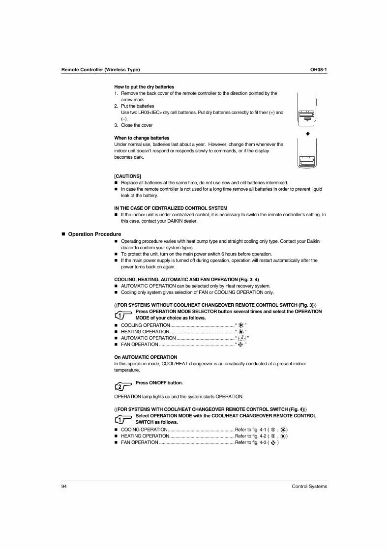
How to put the dry batteries
1. Remove the back cover of the remote controller to the direction pointed by the
arrow mark.
2. Put the batteries
Use two LR03<IEC> dry cell batteries. Put dry batteries correctly to fit their (+ ) and
(– ).
3. Close the cover
When to change batteries
Under normal use, batteries last about a year. However, change them whenever the
indoor unit doesn’t respond or responds slowly to commands, or if the display
becomes dark.
[CAUTIONS]
Replace all batteries at the same time, do not use new and old batteries intermixed.
In case the remote controller is not used for a long time remove all batteries in order to prevent liquid
leak of the battery.
IN THE CASE OF CENTRALIZ ED CONTROL SYSTEM
If the indoor unit is under centraliz ed control, it is necessary to switch the remote controller’s setting. In
this case, contact your DAIK IN dealer.
Operation Procedure
Operating procedure varies with heat pump type and straight cooling only type. Contact your Daikin
dealer to confirm your system types.
To protect the unit, turn on the main power switch 6 hours before operation.
If the main power supply is turned off during operation, operation will restart automatically after the
power turns back on again.
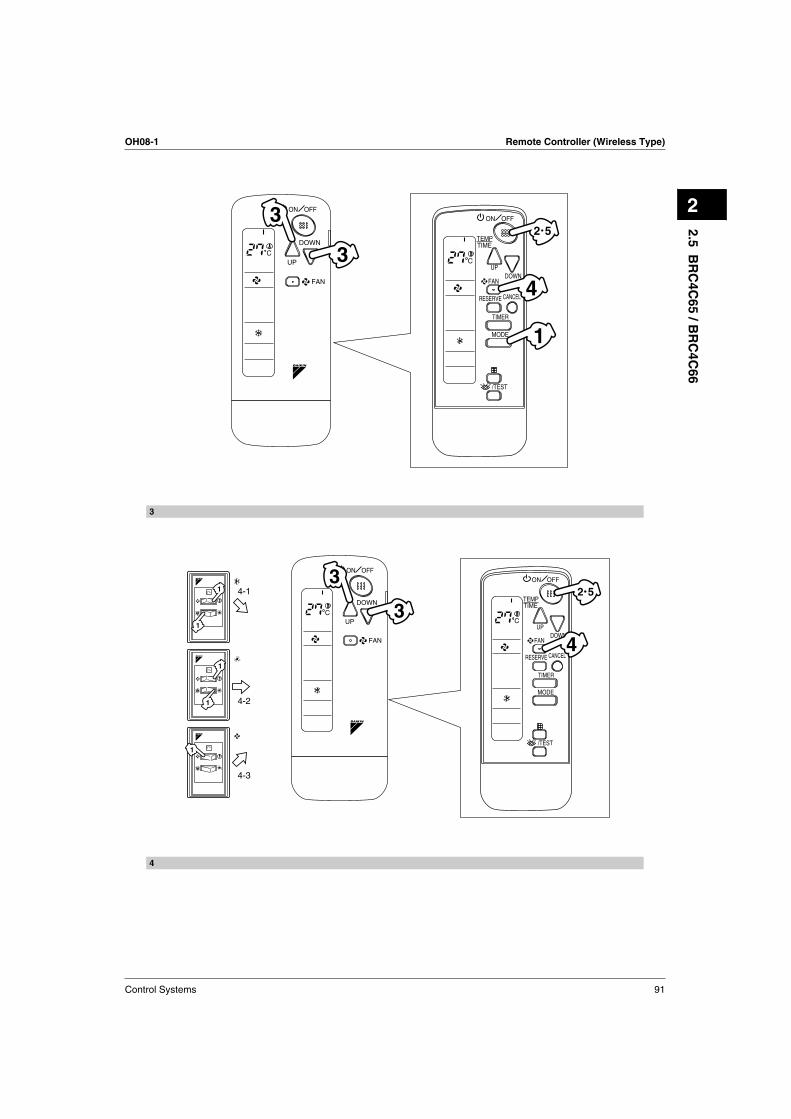
COOLING, HEATING, AUTOMATIC AND FAN OPERATION (Fig. 3, 4)
AUTOMATIC OPERATION can be selected only by Heat recovery system.
Cooling only system gives selection of FAN or COOLING OPERATION only.
⟨⟨FOR SYSTEMS WITHOUT COOL/HEAT CHANGEOVER REMOTE CONTROL SWITCH (Fig. 3)⟩⟩
Press OPERATION MODE SELECTOR button several times and select the OPERATION