DOCUMENTATION SET This document is part of a set. The full list of documents in the set, and the publication numbers under which they can be ordered, is given below. These documents can be provided on request to Siemens Protection Devices Ltd. on +44 191 4015555. They can also be found on our website at www.reyrolle-protection.com.
1.1 Relay Menus And Display.........................................................................................................5 1.2 Operation Guide........................................................................................................................7
1.2.1 User Interface Operation..............................................................................................7 1.3 Settings Display ........................................................................................................................8 1.4 Fault Data Mode......................................................................................................................15 1.5 control mode ...........................................................................................................................15
Section 2: Setting the Relay Using Reydisp Evolution ....................................................................16 2.1 Physical Connection................................................................................................................16
2.1.1 Front USB connection ................................................................................................16 2.1.2 Rear RS485 connection .............................................................................................17 2.1.3 Optional rear fibre optic connection ...........................................................................17 2.1.4 Configuring Relay Data Communication....................................................................18 2.1.5 Connecting to the Relay via Reydisp .........................................................................19
Section 3: Relay Software Upgrade Instructions ..............................................................................20 3.1 General....................................................................................................................................20 3.2 replacing firmware on a product installed on site....................................................................20
3.2.1 Identify Which Software Is Currently Loaded.............................................................20 3.2.2 Overall Software Information......................................................................................20 3.2.3 Product Configuration Information .............................................................................20 3.2.4 Things To Do Before Loading New Firmware/Software.............................................21
3.3 loading code using front usb port............................................................................................21 3.3.1 Solving Software Upload Problems............................................................................23
List of Figures Figure 1.1-1 Menu ....................................................................................................................................5 Figure 1.1-2 Fascia Contrast symbol .......................................................................................................5 Figure 1.1-3 Fascia of a 7SR224 relay (Please note your model may differ from illustration).................6 Figure 3.3-1 PC Reyfresh Window.........................................................................................................22
All relay fascias contain the same access keys although the fascias may differ in appearance from model to model. The basic menu structure is also the same in all products and consists of four main menus, these being,
Settings Mode - allows the user to view and (if allowed via the settings mode password) change settings in the relay.
Instruments Mode - allows the user to view the relay meters e.g. current, voltage etc.
Fault Data Mode - allows the user to view the type and data of any fault detected by the relay.
Control Mode - allows the user to control external plant under the relays control for example the CB (if allowed via the control mode password)
The menus can be viewed via the LCD by pressing the access keys as below,
Figure 1.1-1 Menu
Pressing CANCEL returns to the Identifier screen
LCD Contrast To change the contrast on the LCD insert a flat nosed screwdriver into the screwhead below the contrast symbol, turning the screwhead decreases or increases the contrast of the LCD.
The basic menu structure flow diagram is shown in Figure 1.2-2. This diagram shows the main modes of display: Settings Mode, Instrument Mode, Fault Data Mode and Control Mode.
When the relay leaves the factory all data storage areas are cleared and the settings set to default as specified in settings document.
When the relay is first energised the user is presented with the following message: -
RECLOSER-M 7SR224
_______________________________
ENTER to CONTROL Figure 1.2-1 Relay Identifier Screen
On the factory default setup the relay LCD should display the relay identifier, on each subsequent power-on the screen that was showing before the last power-off will be displayed.
The push-buttons on the fascia are used to display and edit the relay settings via the LCD, to display and activate the control segment of the relay, to display the relays instrumentation and Fault data and to reset the output relays and LED’s.
The five push-buttons have the following functions:
READ DOWN READ UP
Used to navigate the menu structure.
ENTER
The ENTER push-button is used to initiate and accept setting changes.
When a setting is displayed pressing the ENTER key will enter the edit mode, the setting will flash and can now be changed using the▲ or ▼ buttons. When the required value is displayed the ENTER button is pressed again to accept the change.
When an instrument is displayed pressing ENTER will toggle the instruments favourite screen status.
CANCEL
This push-button is used to return the relay display to its initial status or one level up in the menu structure. Pressed repeatedly will return to the Relay Identifier screen. It is also used to reject any alterations to a setting while in the edit mode.
TEST/RESET
This push-button is used to reset the fault indication on the fascia. When on the Relay Identifier screen it also acts as a lamp test button, when pressed all LEDs will momentarily light up to indicate their correct operation. It is also moves the cursor right ► when navigating through menus and settings.
Once the Settings Mode title screen has been located pressing the READ DOWN ▼ button takes the user into the Settings mode sub-menus.
Each sub-menu contains the programmable settings of the relay in separate logical groups. The sub menus are accessed by pressing the TEST/RESET► button. Pressing the ▼ button will scroll through the settings, after the last setting in each sub menu is reached the next sub menu will be displayed. If a particular sub menu is not required to be viewed then pressing ▼ will move directly to the next one in the list.
While a setting is being displayed on the screen the ENTER button can be pressed to edit the setting value. If the relay is setting password protected the user will be asked to enter the password. If an incorrect password is entered editing will not be permitted. All screens can be viewed even if the password is not known.
While a setting is being edited flashing characters indicate the edit field. Pressing the ▲ or ▼ buttons will display the valid field values. If these buttons are held on, the rate of scrolling will increase.
Once editing is complete pressing the ENTER button stores the new setting into the non-volatile memory. The setting change is effective immediately unless any protection element is operating, in which case the change becomes effective when no elements are operating.
The actual setting ranges and default values for each relay model can be found in the appendix to this section of the manual.
The Instrument Mode sub-menu displays key quantities and information to aid with commissioning. The following meters are available and are navigated around by using the ▲,▼and TEST/REST buttons.
Instrument Description
FAVOURITE METERS
→to view
This allows the user to view his previously constructed list of ‘favourite meters’ by pressing TEST/RESET ► button and the READ DOWN button to scroll though the meters added to this sub-group
To construct a sub-group of favourite meters, first go to the desired meter then press ENTER this will cause a message to appear on the LCD ‘Add To Favourites YES pressing ENTER again will add this to the FAVOURITE METERS Sub-menu. To remove a meter from the FAVOURITE METERS sub-menu go to that meter each in the FAVOURITE METERS sub-menu or at its Primary location press ENTER and the message ‘Remove From Favourites’ will appear press ENTER again and this meter will be removed from the FAVOURITE METERS sub-group.
The relay will poll through, displaying each of the meters selected in favourite meters, after no key presses have been detected for a user settable period of time. The time is set in the Setting menu>System Config>Favourite Meters Timer.
CURRENT METERS
→to view
This is the sub-group that includes all the meters that are associated with Current TEST/RESET ► allows access to this sub-group
Primary Current Ia 0.00kA Ib 0.00kA Ic 0.00kA
Displays the 3 phase currents Primary RMS values
Secondary Current Ia 0.00A Ib 0.00A Ic 0.00A
Displays the 3 phase currents Secondary RMS values
Nom Current Ia 0.00xIn ----o Ib 0.00xIn ----o Ic 0.00xIn ----o
Displays the 3 Phase currents Nominal RMS values & phase angles with respect to PPS voltage.
Pri Earth Current IN 0.000kA IG 0.000kA Isef 0.000kA
Displays the 3 Earth currents Primary RMS values
Sec Earth Current IN 0.00A IG 0.00A Isef 0.00A
Displays the 3 Earth currents Secondary RMS values
Nom Earth Current IN 0.000xIn----o IG 0.000xIn----o Isef 0.000xIn----
Displays the 3 Earth currents Nominal RMS values & phase angles with respect to PPS voltage.
I Seq Components Izps 0.00xIn----o Ipps 0.00xIn----o Inps 0.00xIn----o
Displays the Current Sequence components Nominal RMS values & phase angles with respect to PPS voltage.
2nd Harmonic Current Ia 0.00xIn Ib 0.00xIn Ic 0.00xIn
Displays the Voltage Sequence components Nominal RMS values & phase angles with respect to PPS voltage.
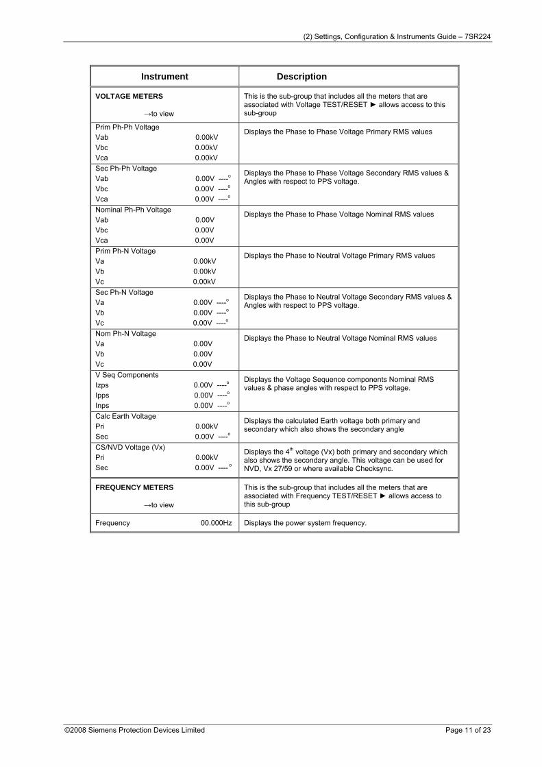
Calc Earth Voltage Pri 0.00kV Sec 0.00V ----o
Displays the calculated Earth voltage both primary and secondary which also shows the secondary angle
CS/NVD Voltage (Vx) Pri 0.00kV Sec 0.00V ---- o
Displays the 4th voltage (Vx) both primary and secondary which also shows the secondary angle. This voltage can be used for NVD, Vx 27/59 or where available Checksync.
FREQUENCY METERS
→to view
This is the sub-group that includes all the meters that are associated with Frequency TEST/RESET ► allows access to this sub-group
Frequency 00.000Hz Displays the power system frequency.
This is the sub-group that includes all the meters that are associated with Power TEST/RESET ► allows access to this sub-group
Phase A 0.0MW Phase B 0.0MW Phase C 0.0MW P (3P) 0.0MW
Displays Real Power
Phase A 0.0MVAr Phase B 0.0MVAr Phase C 0.0MVAr Q (3P) 0.0MVAr
Displays Reactive Power
Phase A 0.0MVA Phase B 0.0MVA Phase C 0.0MVA S (3P) 0.0MVA
Displays Apparent Power
PF A 0.00 PF B 0.00 PF C 0.00 PF (3P) 0.00
Displays Power factor
ENERGY METERS
→to view
This is the sub-group that includes all the meters that are associated with Energy TEST/RESET ► allows access to this sub-group
Active Energy Exp 0.00MWh Imp 0.00MWh
Displays both imported and exported Active Energy
Reactive Energy Exp 0.00MVArh Imp 0.00MVArh
Displays both imported and exported Reactive Energy
DIRECTIONAL METERS
→to view
This is the sub-group that includes all the meters that are associated with Directional elements TEST/RESET ► allows access to this sub-group. Only seen on models that have the 67 option
P/F Dir (67) ------------------------------------------------------ No Dir, PhA Fwd, PhA Rev, PhB Fwd, PhB Rev, PhC Fwd, PhC Rev
The appropriate values from the selection will be displayed.
Calc E/F Dir (67N) ------------------------------------------------------ No Dir, E/F Fwd, E/F Rev
The appropriate values from the selection will be displayed.
Meas E/F Dir (67G) ------------------------------------------------------ No Dir, E/F Fwd, E/F Rev
The appropriate values from the selection will be displayed.
SEF Dir (67SEF) ------------------------------------------------------ No Dir, SEF Fwd, SEF Rev
The appropriate values from the selection will be displayed.
THERMAL METERS
→to view
This is the sub-group that includes all the meters that are associated with Thermal TEST/RESET ► allows access to this sub-group
This is the sub-group that includes all the meters that are associated with Autoreclose TEST/RESET ► allows access to this sub-group. Only seen on models that have the 79 option
79 AR State AR Close Shot 0
MAINTENANCE METERS
→to view
This is the sub-group that includes all the meters that are associated with Maintenance TEST/RESET ► allows access to this sub-group
CB Total Trips Count Target 10000
Displays the number of CB trips experienced by the CB. Increments on each trip command issued
CB Delta Trips Count Target 10000
Additional counter which can be reset independently displays the number of CB trips experienced by the CB after the last visit to the substation
CB Count To AR Block Count Target 10000
Displays the number of CB trips experienced by the CB. When the target is reached the relay will only do 1 Delayed Trip to Lockout.
CB Freq Ops Count Count Target 10000
Displays the number of CB trips experienced by the CB over the last rolling 1 hr period. When the target is reached the relay will only do 1 Delayed Trip to Lockout.
CB Wear Phase A 0.00MA^2s Phase B 0.00MA^2s Phase C 0.00MA^2s
Displays the current measure of circuit breaker wear.
GENERAL ALARM METERS
→to view
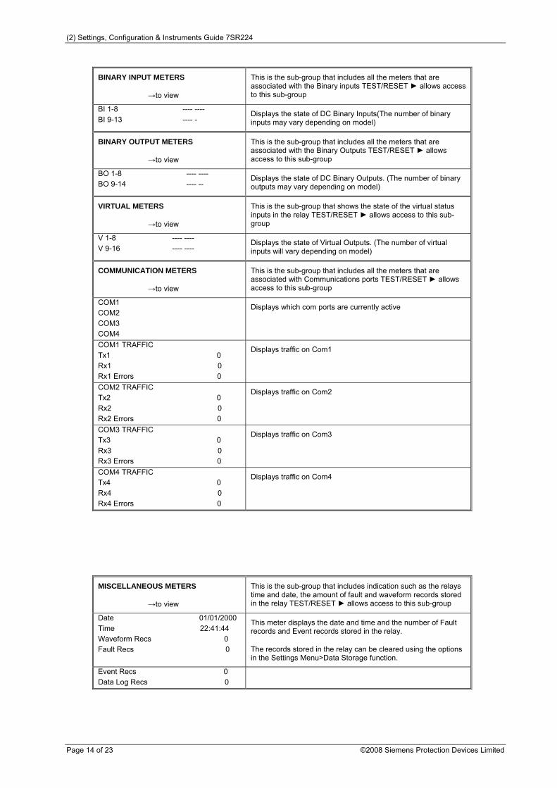
This is the sub-group that includes all the meters that are associated with the Binary inputs TEST/RESET ► allows access to this sub-group
This is the sub-group that includes all the meters that are associated with the Binary inputs TEST/RESET ► allows access to this sub-group
BI 1-8 ---- ---- BI 9-13 ---- -
Displays the state of DC Binary Inputs(The number of binary inputs may vary depending on model)
BINARY OUTPUT METERS
→to view
This is the sub-group that includes all the meters that are associated with the Binary Outputs TEST/RESET ► allows access to this sub-group
BO 1-8 ---- ---- BO 9-14 ---- --
Displays the state of DC Binary Outputs. (The number of binary outputs may vary depending on model)
VIRTUAL METERS
→to view
This is the sub-group that shows the state of the virtual status inputs in the relay TEST/RESET ► allows access to this sub-group
V 1-8 ---- ---- V 9-16 ---- ----
Displays the state of Virtual Outputs. (The number of virtual inputs will vary depending on model)
COMMUNICATION METERS
→to view
This is the sub-group that includes all the meters that are associated with Communications ports TEST/RESET ► allows access to this sub-group
COM1 COM2 COM3 COM4
Displays which com ports are currently active
COM1 TRAFFIC Tx1 0 Rx1 0 Rx1 Errors 0
Displays traffic on Com1
COM2 TRAFFIC Tx2 0 Rx2 0 Rx2 Errors 0
Displays traffic on Com2
COM3 TRAFFIC Tx3 0 Rx3 0 Rx3 Errors 0
Displays traffic on Com3
COM4 TRAFFIC Tx4 0 Rx4 0 Rx4 Errors 0
Displays traffic on Com4
MISCELLANEOUS METERS
→to view
This is the sub-group that includes indication such as the relays time and date, the amount of fault and waveform records stored in the relay TEST/RESET ► allows access to this sub-group
Date 01/01/2000 Time 22:41:44 Waveform Recs 0 Fault Recs 0
This meter displays the date and time and the number of Fault records and Event records stored in the relay.
The records stored in the relay can be cleared using the options in the Settings Menu>Data Storage function.
The Fault Data Mode sub menu lists the time and date of the previous ten protection operations. The stored data about each fault can be viewed by pressing the TEST/RESET► button. Each record contains data on the operated elements, analogue values and LED flag states at the time of the fault. The data is viewed by scrolling down using the ▼ button.
1.5 CONTROL MODE
This mode provides convenient access to commonly used relay control and test functions. When any of the items listed below are selected control is initiated by pressing the ENTER key. The TEST/RESET► button is used to toggle between the available options. The user is prompted to confirm the action, again by pressing the ENTER key, before the command is executed. If the action is not confirmed within a short time the action is automatically cancelled.
Control Mode commands are password protected using the Control Password function
Section 2: Setting the Relay Using Reydisp Evolution To set the relay using the communication port the user will need the following:- PC with REYDISP Evolution Installed. (This can be download from our website www.reyrolle-protection.com and found under the submenu ‘Software’)This software requires windows 2000-service pack 4 or above, or windows XP with service pack 2 or above.
2.1 PHYSICAL CONNECTION
The relay can be connected to Reydisp via any of the communication ports on the relay. Suitable communication Interface cable and converters are required depending which port is being used.
2.1.1 Front USB connection To connect your pc locally via the front USB port.
Figure 2.1-3 Fibre Optic Connection to PC Sigma devices have a 25 pin female D connector with the following pin out.
Pin Function 2 Transmit Data 3 Received Data 4 Request to Send 5 Clear to Send 6 Data set ready 7 Signal Ground 8 Received Line Signal Detector 20 Data Terminal Ready
2.1.4 Configuring Relay Data Communication Using the keys on the relay fascia scroll down the settings menu’s into the ‘communications’ menu and change the settings for the communication port used on the relay. All of the below settings may not be available in all relay types. Reydisp software uses IEC60870-5-103 protocol to communicate.
COM1-RS485 Port
COM2-USB Port
COM3 – Optional Fibre Optic
COM4 – Optional Fibre Optic
Setting name Range Default Units Notes
Station Address 0 … 254 0
Address given to relay to identify that relay from others which may be using the same path for communication as other relays for example in a fibre optic hub
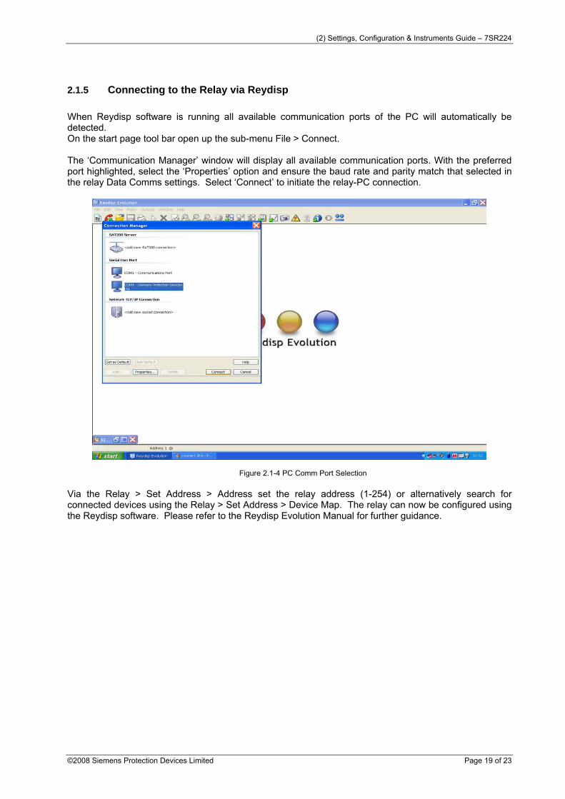
2.1.5 Connecting to the Relay via Reydisp When Reydisp software is running all available communication ports of the PC will automatically be detected. On the start page tool bar open up the sub-menu File > Connect. The ‘Communication Manager’ window will display all available communication ports. With the preferred port highlighted, select the ‘Properties’ option and ensure the baud rate and parity match that selected in the relay Data Comms settings. Select ‘Connect’ to initiate the relay-PC connection.
Figure 2.1-4 PC Comm Port Selection
Via the Relay > Set Address > Address set the relay address (1-254) or alternatively search for connected devices using the Relay > Set Address > Device Map. The relay can now be configured using the Reydisp software. Please refer to the Reydisp Evolution Manual for further guidance.
3.1 GENERAL Please read thoroughly all of these instructions before starting the download process.
• If you are loading firmware into a product that is already installed on site then follow the instructions in section 2, 3 and 4.
• Otherwise skip directly to section 3 to load firmware into the device.
3.2 REPLACING FIRMWARE ON A PRODUCT INSTALLED ON SITE
3.2.1 Identify Which Software Is Currently Loaded With the relay connected to a suitable DC supply. Press CANCEL several times to ensure that you are at the root of the menu system. The relay will typically display the relay model name or circuit name. On newer relay models press CANCEL and TEST to bring up the
menu. On older relay models press and hold CANCEL, press and hold TEST, press and hold ENTER
should appear. Whilst still pressing ENTER release the other keys. Navigate to the software information screen using the TEST/RESET-> button. The following typical information uniquely identifies a particular relay model. (Older relay models may only display a subset of this information).
3.2.2 Overall Software Information Software Art No This is the application software code used which may common to many relay
variants. Build Date This is the date when the software was compiled. Build Time This is time when the software was compiled. Code CRC This is the CRC check code of the software code. Boot Block Art No This is the boot block software code responsible for loading in new application
software code.
3.2.3 Product Configuration Information Product Art No This is the Products unique configuration article number. Product Name This is the Products unique model name. Release Date This is the date when this particular configuration was released. Release Time This is the time when this particular configuration was released.
3.2.4 Things To Do Before Loading New Firmware/Software Please make a hard copy of all relay settings prior to changing the code as all settings will be lost during the code upload process. It is usually possible to download the existing settings into Reydisp Evolution and then reload these settings into the relay. Reydisp will highlight any changes that it cannot automatically resolve for you to manually correct. If the relay is in service then it is advisable to remove any TRIP LINKS to prevent in-advertent mal-operation due to incorrect settings being applied. The attachments are password protected self extracting zip files to prevent email systems discarding them or modifying them which should be saved with the "EX" extension renamed to be "EXE". The password that is applied to this zip file is "REYROLLE" in capital letters.
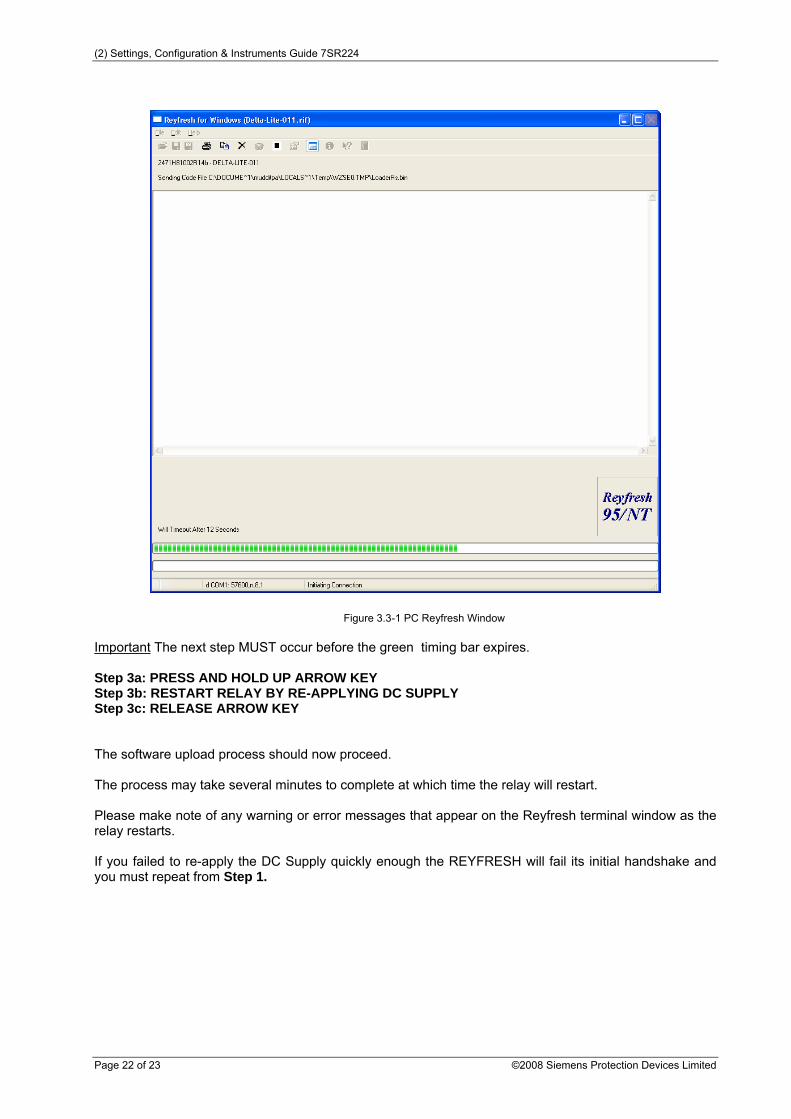
3.3 LOADING CODE USING FRONT USB PORT New firmware/software may be loaded via the USB port on the front Fascia. To load the code, connect up a PC USB to the relay front USB port. The relay will only accept new firmware during RESTART. The easiest way to do this is to firstly remove the DC supply. (See below for alternative techniques if you do not wish to remove the DC supply) Please familiarise yourself with the next three steps BEFORE proceeding. Step 1 : REMOVE DC SUPPLY Step 2 : RUN APPROPRIATE CODE LOADER PROGRAM FOR THIS DEVICE Wait for the REYFRESH window to open and a green timing bar can be seen to be counting down at the bottom of the window (Press the PLAY button '>' if the download does not automatically start).
Figure 3.3-1 PC Reyfresh Window Important The next step MUST occur before the green timing bar expires. Step 3a: PRESS AND HOLD UP ARROW KEY Step 3b: RESTART RELAY BY RE-APPLYING DC SUPPLY Step 3c: RELEASE ARROW KEY The software upload process should now proceed. The process may take several minutes to complete at which time the relay will restart. Please make note of any warning or error messages that appear on the Reyfresh terminal window as the relay restarts. If you failed to re-apply the DC Supply quickly enough the REYFRESH will fail its initial handshake and you must repeat from Step 1.
3.3.1 Solving Software Upload Problems The relay will auto detect the download baud rate and will use whatever baud rate set within Reyfresh. However the default and maximum baud rate of 460800 bits/sec is preferred The download procedure has been tested on Windows 98,NT and XP. On Windows 98 it may be necessary to add the line :- shell=C:\COMMAND.COM C:\ /e:4056 /p to the file C:\CONFIG.SYS to increase the environment space. When the relay restarts, messages appear on the LCD to confirm the number of I/O modules fitted, please press the ENTER key when requested if the details displayed are correct.


![Turnkey Instruments Ltd · Osiris 8 Operating Instructions 9 OSIRIS Settings: the instrument is provided with several settings which can changed by the user . Press [ ] to say YES](https://static.documents.pub/doc/80x56/5f712598b7cbdc55586e0a9f/turnkey-instruments-ltd-osiris-8-operating-instructions-9-osiris-settings-the-instrument.jpg)


