Symbol Example Flow l/min (GPM) Pressure bar (PSI) Type Code Cartridge Size 04; D02 Size 06; D03 Size 10; D05 Line Mounted Page Data Sheet Load Shuttle Valves 8 (2) 500 (7300) LV1-043 X (X) 150 HA 5008 8 (2) 500 (7300) LV2-043 X (X) 152 HA 5028 40 (11) 320 (4600) LV1-063/S X (X) 154 HA 5015 40 (11) 320 (4600) LV1-063/M X 156 HA 5030 15 (4) 210 (3000) VJL2-304 X 158 HA 5007 20 (5) 250 (3600) SH1F-A3 X 160 HA 5029 Check Valves 20 (5) 320 (4600) VJO1-06/S X X 162 HA 5004 80 (21) 350 (5100) VJO1-10/S X X 164 HA 5307 30 (8) 320 (4600) VJO1-04/M X 166 HA 5012 40 (11) 420 (6100) SC1F-A2 X (X) (X) 168 HA 5010 40 (11) 420 (6100) SC1F-A3 X (X) (X) 170 HA 5016 120 (32) 420 (6100) SC1F-B2 X (X) (X) 172 HA 5017 50 (13) 350 (5100) MVJ3-06 X 174 HA 5018 100 (26) 350 (5100) MVJ3-10 X 176 HA 5020 400 (106) 320 (4600) VJ3 X X 178 HA 5009 Check Valves, One-Way Throttling 250 (66) 320 (4600) VJS3 X X 180 HA 5019 Pilot Operated Check Valves, Pilot to Open 20 (5) 250 (3600) RJV1-05 X 182 HA 5111 20 (5) 320 (4600) VJR1-04/M X 184 HA 5023 30 (8) 350 (5100) SC5H-Q3/I X (X) 186 HA 5217 60 (16) 320 (4600) 2RJV1-06/M X 188 HA 5021 90 (24) 350 (5100) SC5H-R3/I X (X) 190 HA 5218 90 (24) 350 (5100) SCD5H-R3/I X (X) 192 HA 5219 140 (37) 350 (5100) VJR3-10/M X 194 HA 5035 120 (32) 350 (5100) SC5H-S3/I X (X) 196 HA 5220 Pilot Operated Check Valves, Pilot to Close 30 (8) 350 (5100) SCC5H-Q3/I X (X) 198 HA 5221 120 (32) 350 (5100) SCC5H-S3/I X (X) 200 HA 5222 Content 2 Check Valves 3 1 2 1 2 3 Page X www.argo-hytos.com Subject to change · EN · 0417 Notes 2 Check Valves Page X www.argo-hytos.com Subject to change · EN · 0417 Page 148 Page 149 2 2 3 4 5 6 7 8 9 10 11 12 13 1 2 3 4 5 6 7 8 9 10 11 12 13 1 2
Characteristics measured at ν = 32 mm2/s (156 SUS)
› Rapid response to changes in load direction
› Hardened precision parts
› Sharp-edged steel seats for dirt-tolerant performance
› Leak-free closing, suitable for fast cycling with long life
› Compact design for limited installation space availability
› In the standard version, the valve is without surface coating
A high pressure shuttle valve in the form of a screw-in cartridge. This valve prioritizes the respective higher pressure signal from either port 1 or 2. Tightness between ports 1 and 3 is ensured by a sharp-edge steel valve seat.
Pre
ssure
dro
p ∆
p [bar
(PSI)]
Flow Q [l/min (GPM)]
Valve size / Cartridge cavity G1/8 / QY3
Max. low l/min (GPM) 8 (2.1)
Max. operating pressure bar (PSI) 500 (7250)
Fluid temperature range (NBR) °C (°F) -30 .... +100 (-22 ... +212)
Fluid temperature range (FPM) °C (°F) -20 .... +120 (-4 ... +248)
Mass kg (Ibs) 0.01 (0.022)
Datasheet Type
General information GI_0060 Products and operating conditions
Characteristics measured at ν = 32 mm2/s (156 SUS)
› Hardened and precision working parts
› Leak-free in closed position
› Fast response to load direction changes
› Compact size with small instalation space
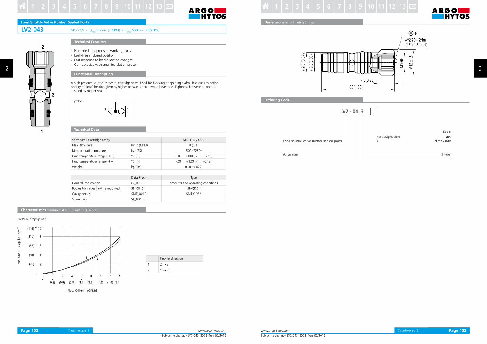
A high pressure shuttle, screw-in, cartridge valve. Used for blocking or opening hydraulic circuits to deine priority of low/direction given by higher pressure circuit over a lower one. Tightness between all ports is ensured by rubber seal.
Pre
ssure
dro
p ∆
p [bar
(PSI)]
Flow Q [l/min (GPM)]
Valve size / Cartridge cavity M12x1,5 / QD3
Max. low rate l/min (GPM) 8 (2.1)
Max. operating pressure bar (PSI) 500 (7250)
Fluid temperature range (NBR) °C (°F) -30 .... +100 (-22 ... +212)
Fluid temperature range (FPM) °C (°F) -20 .... +120 (-4 ... +248)
Weight kg (Ibs) 0,01 (0.022)
Data Sheet Type
General information GI_0060 products and operating conditions
Characteristics measured at ν = 32 mm2/s (156 SUS)
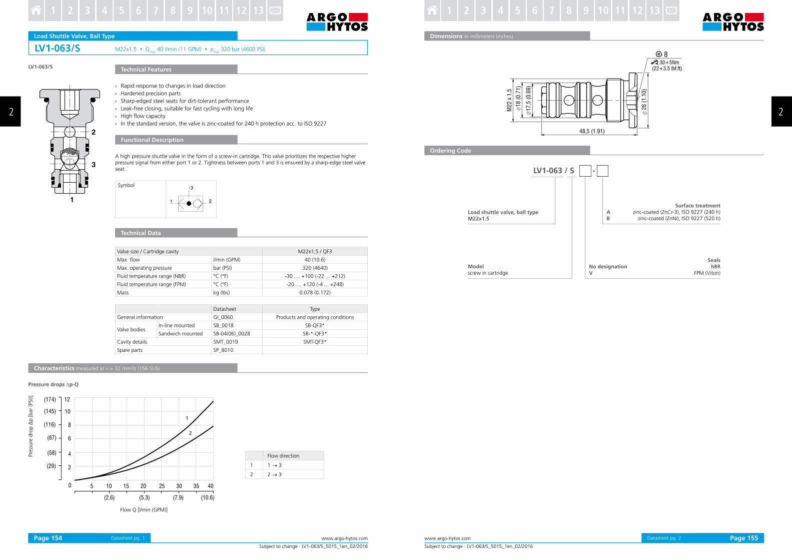
› Rapid response to changes in load direction
› Hardened precision parts
› Sharp-edged steel seats for dirt-tolerant performance
› Leak-free closing, suitable for fast cycling with long life
› High low capacity
› In the standard version, the valve is zinc-coated for 240 h protection acc. to ISO 9227
A high pressure shuttle valve in the form of a screw-in cartridge. This valve prioritizes the respective higher pressure signal from either port 1 or 2. Tightness between ports 1 and 3 is ensured by a sharp-edge steel valve seat.
Pre
ssure
dro
p ∆
p [bar
(PSI)]
Flow Q [l/min (GPM)]
Valve size / Cartridge cavity M22x1,5 / QF3
Max. low l/min (GPM) 40 (10.6)
Max. operating pressure bar (PSI) 320 (4640)
Fluid temperature range (NBR) °C (°F) -30 .... +100 (-22 ... +212)
Fluid temperature range (FPM) °C (°F) -20 .... +120 (-4 ... +248)
Mass kg (Ibs) 0.078 (0.172)
Datasheet Type
General information GI_0060 Products and operating conditions
Valve bodiesIn-line mounted SB_0018 SB-QF3*
Sandwich mounted SB-04(06)_0028 SB-*-QF3*
Cavity details SMT_0019 SMT-QF3*
Spare parts SP_8010
Pressure drops ∆p-Q
Flow direction
1 1 → 3
2 2 → 3
830+5Nm
(22+3.5 Ibf.ft)
∅ 17,5
(0.6
9)
18 (
0.7
1)
M22 x
1,5
48,5 (1.91)
28 (
1.1
0)
∅ ∅
LV1-063 / S -
AB
Subject to change · LV1-063/S_5015_1en_02/2016
www.argo-hytos.com Page 2Datasheet pg. 2
Dimensions in millimeters (inches)
Ordering Code
Load shuttle valve, ball typeM22x1.5
No designationV
Surface treatmentzinc-coated (ZnCr-3), ISO 9227 (240 h)
Characteristics measured at ν = 32 mm2/s (156 SUS)
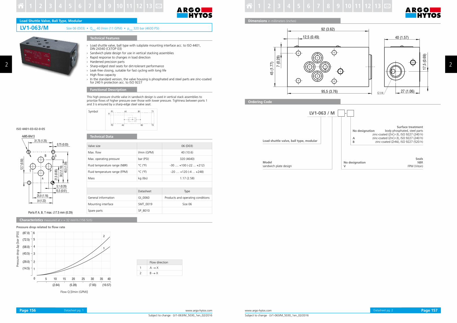
This high pressure shuttle valve in sandwich design is used in vertical stack assemblies to prioritze lows of higher pressure over those with lower pressure. Tightness between ports 1 and 3 is ensured by a sharp-edge steel valve seat.
Pre
ssure
dro
p ∆
p [bar
(PSI)]
Flow Q [l/min (GPM)]
Valve size 06 (D03)
Max. low l/min (GPM) 40 (10.6)
Max. operating pressure bar (PSI) 320 (4640)
Fluid temperature range (NBR) °C (°F) -30 .... +100 (-22 ... +212)
Fluid temperature range (FPM) °C (°F) -20 .... +120 (-4 ... +248)
Mass kg (Ibs) 1.17 (2.58)
Datasheet Type
General information GI_0060 Products and operating conditions
Mounting interface SMT_0019 Size 06
Spare parts SP_8010
Pressure drop related to low rate
› Load shuttle valve, ball type with subplate mounting interface acc. to ISO 4401, DIN 24340 (CETOP 03)
› Sandwich plate design for use in vertical stacking assemblies
› Rapid response to changes in load direction
› Hardened precision parts
› Sharp-edged steel seats for dirt-tolerant performance
› Leak-free closing, suitable for fast cycling with long life
› High low capacity
› In the standard version, the valve housing is phosphated and steel parts are zinc-coated for 240 h protection acc. to ISO 9227
Flow direction
1 A → X
2 B → X
Datasheet pg. 1
95,5 (3.76)
92 (3.62)
40 (1.57)
45
(1
.77
)
12,5 (0.49)
7 (
0.2
8)
27 (1.06)
17
,5 (
0.6
9)
G1/4
LV1-063 / M -
Subject to change · LV1-063/M_5030_1en_02/2016
www.argo-hytos.com Page 2
Dimensions in millimeters (inches)
Ordering Code
Load shuttle valve, ball type, modular
SealsNBR
FPM (Viton)
Modelsandwich plate design
No designation V
No designation
AB
Surface treatmentbody phosphated, steel parts
zinc-coated (ZnCr-3), ISO 9227 (240 h)zinc-coated (ZnCr-3), ISO 9227 (240 h)
Characteristics measured at ν = 32 mm2/s (156 SUS)
› Rapid response to changes in load direction
› Hardened precision parts
› Sharp-edged steel seats for dirt-tolerant performance
› Leak-free closing, suitable for fast cycling with long life
› Compact design for limited installation space availability
› In the standard version, the valve is without surface coating
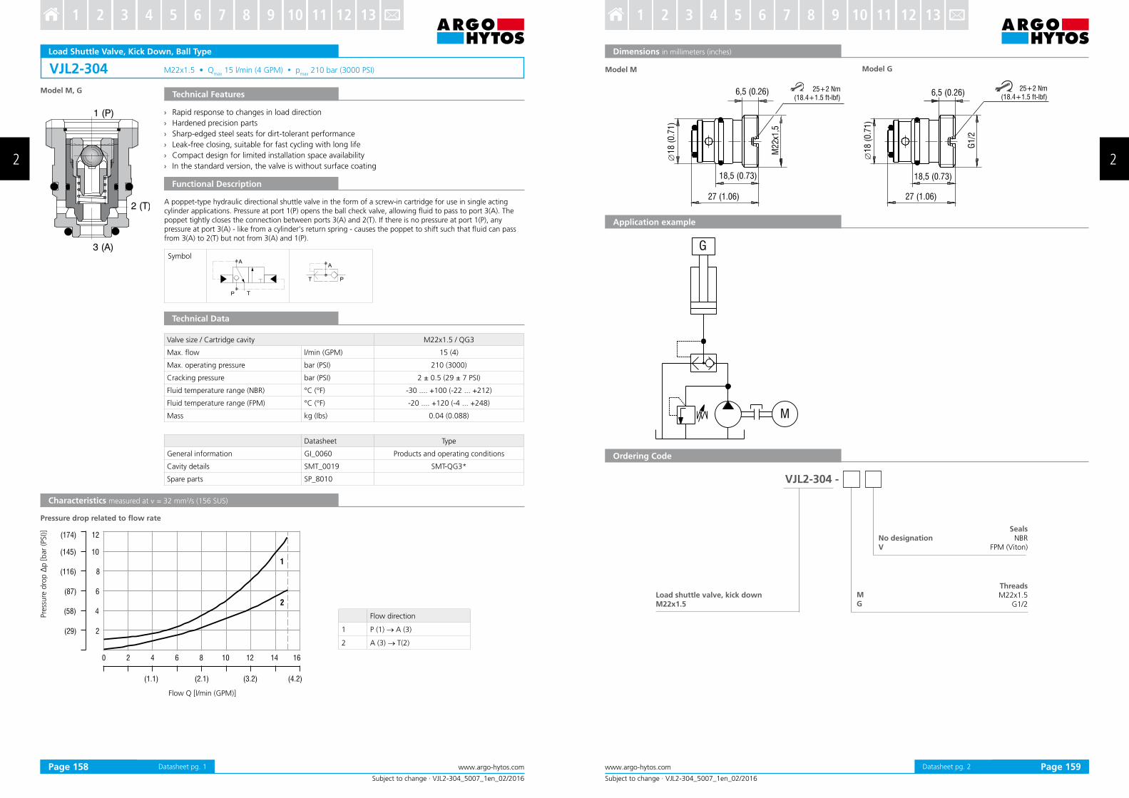
A poppet-type hydraulic directional shuttle valve in the form of a screw-in cartridge for use in single acting cylinder applications. Pressure at port 1(P) opens the ball check valve, allowing luid to pass to port 3(A). The poppet tightly closes the connection between ports 3(A) and 2(T). If there is no pressure at port 1(P), any pressure at port 3(A) - like from a cylinder‘s return spring - causes the poppet to shift such that luid can pass from 3(A) to 2(T) but not from 3(A) and 1(P).
Pre
ssure
dro
p ∆
p [bar
(PSI)]
Flow Q [l/min (GPM)]
Valve size / Cartridge cavity M22x1”5 / QG3
Max. low l/min (GPM) 15 (4)
Max. operating pressure bar (PSI) 210 (3000)
Cracking pressure bar (PSI) 2 ± 0.5 (29 ± 7 PSI)
Fluid temperature range (NBR) °C (°F) -30 .... +100 (-22 ... +212)
Fluid temperature range (FPM) °C (°F) -20 .... +120 (-4 ... +248)
Mass kg (Ibs) 0.04 (0.088)
Datasheet Type
General information GI_0060 Products and operating conditions
› Sharp“edged steel seats for dirt“tolerant performance
› Leak“free closing’ suitable for fast cycling with long life
› High low capacity
› In the standard version’ the valve is zinc“coated for 240 h protection acc” to ISO 9227
Functional Description
A poppet type hydraulic directional shuttle valve in the form of a screw“in cartridge for use in single acting cylinder applications” Pressure at port 1(P) opens the ball check valve’ allowing luid to pass to port 3(A)” The poppet tightly closes the connection between ports 3(A) and 2(T)” If there is no pressure at port 1(P)’ any pressure at port 3(A) “ like from a cylinder s return spring “ causes the poppet to shift such that luid can pass from 3(A) to 2(T) but not from 3(A) and 1(P)”
Characteristics measured at ν = 32 mm2/s (156 SUS)
Pressure drop related to low rate
Pre
ssure
dro
p ∆
p [bar
(PSI)]
Flow Q [l/min (GPM)]
Flow direction
1 P (1) → A (3)
2 A (3) → T (2)
Valve size / Cartridge cavity 3/4-16 UNF-2A / A3
Max” low l/min (GPM) 20 (5”3)
Max” operating pressure bar (PSI) 250 (3630)
Cracking pressure bar (PSI) 2 ± 0’5 (29 ± 7 PSI)
Fluid temperature range (NBR) °C (°F) “30 ”””” ‘100 (“22 ””” ‘212)
Fluid temperature range (FPM) °C (°F) “20 ”””” ‘120 (“4 ””” ‘248)
Mass kg (Ibs) 0”08 (0”18)
Datasheet Type
General information GI_0060 Products and operating conditions
Cartridge cavity / Form tools SMT_0019 SMT“A3
Spare parts SP_8010
Technical Data
3/4
-16
UN
F-2
A
39,5(1.56)
48(1.89)
24
�1
4,2
2(0
.56
)
�1
5,8
2(0
.62
)
6
�2
6,5
(1.0
4)
60+2 Nm(44.3+1.5 ft-lbf)
M
G
SH1F-A3 / -
VersionLightline
AB
L
020
A3
Subject to change · SH1F-A3_5029_1en_02/2016
www.argo-hytos.com Page 2Datasheet pg” 2
Dimensions in millimeters (inches)
Application example
Ordering Code
Load shuttle valve, kick down3/4-16 UNF
SealsNBR
FPM (Viton)
Cracking pressure
2 ± 0”5 bar (29 ± 7 PSI)
Surface treatmentzinc“coated (ZnCr“3)’ ISO 9227 (240 h)
Characteristics measured at ν = 32 mm2/s (156 SUS)
› Hardened precision parts
› Sharp-edged steel seats for dirt-tolerant performance
› Leak-free closing, suitable for fast cycling with long life
› Compact design for limited installation space availability
› High low capacity
› In the standard version, the valve is without surface coating
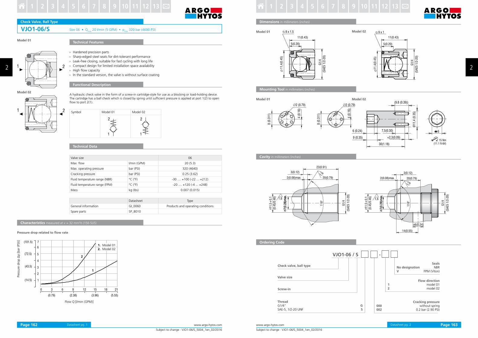
A hydraulic check valve in the form of a screw-in cartridge-style for use as a blocking or load-holding device. The cartridge has a ball check which is closed by spring until suficient pressure is applied at port 1(2) to open low to port 2(1).
Pre
ssure
dro
p ∆
p [bar
(PSI)]
Flow Q [l/min (GPM)]
Valve size 06
Max. low l/min (GPM) 20 (5.3)
Max. operating pressure bar (PSI) 320 (4640)
Cracking pressure bar (PSI) 0.25 (3.62)
Fluid temperature range (NBR) °C (°F) -30 .... +100 (-22 ... +212)
Fluid temperature range (FPM) °C (°F) -20 .... +120 (-4 ... +248)
Mass kg (Ibs) 0.007 (0.015)
Datasheet Type
General information GI_0060 Products and operating conditions
› Sharp-edged steel seats for for dirt-tolerant performance
› Leak-free closing, suitable for fast cycling with long life
› Compact design for limited installation space availability
› High low capacity
› In the standard version, the valve is without surface coating
A hydraulic check valve in the form of a screw-in cartridge-style for use as a blocking or load-holding device. The cartridge has a ball check which is closed by spring until suficient pressure is applied at port 1 to open low to port 2.
Pre
ssure
dro
p ∆
p [bar
(PSI)]
Flow Q [l/min (GPM)]
Valve size 10 / M20x1.5
Max. low l/min (GPM) 80 (21.1)
Max. operating pressure bar (PSI) 350 (5076)
Cracking pressure bar (PSI) 0.5 (7.25)
Fluid temperature range (NBR) °C (°F) -30 .... +100 (-22 ... +212)
Fluid temperature range (FPM) °C (°F) -20 .... +120 (-4 ... +248)
Mass kg (Ibs) 0.017 (0.038)
Datasheet Type
General information GI_0060 Products and operating conditions
Spare parts SP_8010
Characteristics measured at ν = 32 mm2/s (156 SUS)
› Poppet type check valve with subplate mounting interface acc. to ISO 4401, DIN 24340 (CETOP 02)
› Sandwich plate design for use in vertical stacking assemblies
› Leak-free closing in one or two channels, suitable for fast cycling with long life
› Sharp-edged steel seats for dirt-tolerant performance
› High low capacity
› Optional bias spring ranges for back-pressure control
› In the standard version, the valve housing is phosphated and steel parts are zinc-coated for 240 h protection acc. to ISO 9227
Technical Features
Characteristics measured at ν = 32 mm2/s (156 SUS)
Technical Data
Pressure drop related to low rate
Flow Q [l/min (GPM)]
Pre
ssure
dro
p ∆
p [bar
(PSI)]
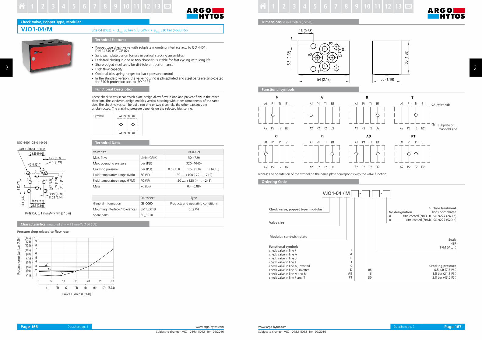
These check valves in sandwich plate design allow low in one and prevent low in the other direction. The sandwich design enables vertical stacking with other components of the same size. The check valves can be built into one or two channels, the other passages are unobstructed. The cracking pressure depends on the selected bias spring.
Functional Description
Valve size 04 (D02)
Max. low l/min (GPM) 30 (7.9)
Max. operating pressure bar (PSI) 320 (4640)
Cracking pressure bar (PSI) 0.5 (7.3) 1.5 (21.8) 3 (43.5)
Fluid temperature range (NBR) °C (°F) -30 .... +100 (-22 ... +212)
Fluid temperature range (FPM) °C (°F) -20 .... +120 (-4 ... +248)
Mass kg (Ibs) 0.4 (0.88)
Datasheet Type
General information GI_0060 Products and operating conditions
Mounting interface / Tolerances SMT_0019 Size 04
Spare parts SP_8010
Datasheet pg. 1
G
16 (0.63)
5,5
(0
.22
)
54 (2.13) 30 (1.18)
35
(1
.38
)
A2
T2
P2
B2
A B
C D AB
P T
PT
P
A
B
T
C
D
ABPT
05
15
30
VJO1-04 / M - -
Subject to change · VJO1-04/M_5012_1en_02/2016
www.argo-hytos.com 2 Page 2
Dimensions in millimeters (inches)
valve side
subplate or manifold side
Functional symbols
Notes: The orientation of the symbol on the name plate corresponds with the valve function.
Ordering Code
Check valve, poppet type, modular
Valve size
Functional symbolscheck valve in line Pcheck valve in line Acheck valve in line Bcheck valve in line Tcheck valve in line A, invertedcheck valve in line B, invertedcheck valve in line A and Bcheck valve in line P and T
SealsNBR
FPM (Viton)
Cracking pressure0.5 bar (7.3 PSI)
1.5 bar (21.8 PSI)3.0 bar (43.5 PSI)
Surface treatmentbody phosphated
zinc-coated (ZnCr-3), ISO 9227 (240 h)zinc-coated (ZnNi), ISO 9227 (520 h)
Characteristics measured at ν = 32 mm2/s (156 SUS)
› Hardened precision parts
› Sharp“edged steel seats for dirt“tolerant performance
› Leak“free closing’ suitable for fast cycling with long life
› High low capacity
› Optional bias spring ranges for back“pressure control
› In the standard version’ the valve is zinc“coated for 240 h protection acc” to ISO 9227
A hydraulic check valve in the form of a screw“in cartridge“style for use as a blocking or load“holding device” The cartridge has a ball check which is closed by spring until suficient pressure is applied at port 1 to open low to port 2”
Pressure drop related to low rate
Pre
ssure
dro
p ∆
p [bar
(PSI)]
Flow Q [l/min (GPM)]
Valve size / Cartridge cavity 3/4-16 UNF-2A / A2
Max” low l/min (GPM) 40 (10”6)
Max” operating pressure bar (PSI) 420 (6090)
Cracking pressurebar 0”5 1”5 3”5 7”0
(PSI) (7”3) (21”8) (50”8) (101”5)
Fluid temperature range (NBR) °C (°F) “30 ”””” ‘100 (“22 ””” ‘212)
Fluid temperature range (FPM) °C (°F) “20 ”””” ‘120 (“4 ””” ‘248)
Mass kg (Ibs) 0”06 (0”13)
Datasheet Type
General information GI_0060 Products and operating conditions
Valvebodies
In-line mounted SB_0018 SB“A2*
Sandwich mounted SB“04(06)_0028 SB“*A2*
Cavity details / Form tools SMT_0019 SMT“A2*
Spare parts SP_8010
Technical Data
27,5 (1.08)
24(0
,94)
12
,65
(0.4
9)
27
(1
.06
)
24
3/4
-16 U
NF-
2A
38,5(1.52)
60+2 Nm
(44.3+1.5 ft-lbf)
SC1F-A2 / -
Check valve, ball type 3/4-16 UNF
High performance
AB
H
000002005015035070
Subject to change · SC1F-A2_5010_1en_02/2016
www.argo-hytos.com 2 Page 2Datasheet pg” 2
Dimensions in millimeters (inches)
Ordering Code
Cracking pressure without spring
0”2 bar (2”92 PSI)0”5 bar (7”3 PSI)
1”5 bar (21”8 PSI) 3”5 bar (50”8 PSI)
7”0 bar (101”5 PSI)
SealsNBR
FPM (Viton)
Surface treatmentzinc“coated (ZnCr“3)’ ISO 9227 (240 h)
Characteristics measured at ν = 32 mm2/s (156 SUS)
› Hardened precision parts
› Sharp-edged steel seats for dirt-tolerant performance
› Leak-free closing, suitable for fast cycling with long life
› Integrated pressure gauge port G 1/4” or SAE
› In the standard version, the valve is zinc-coated for 240 h protection acc. to ISO 9227
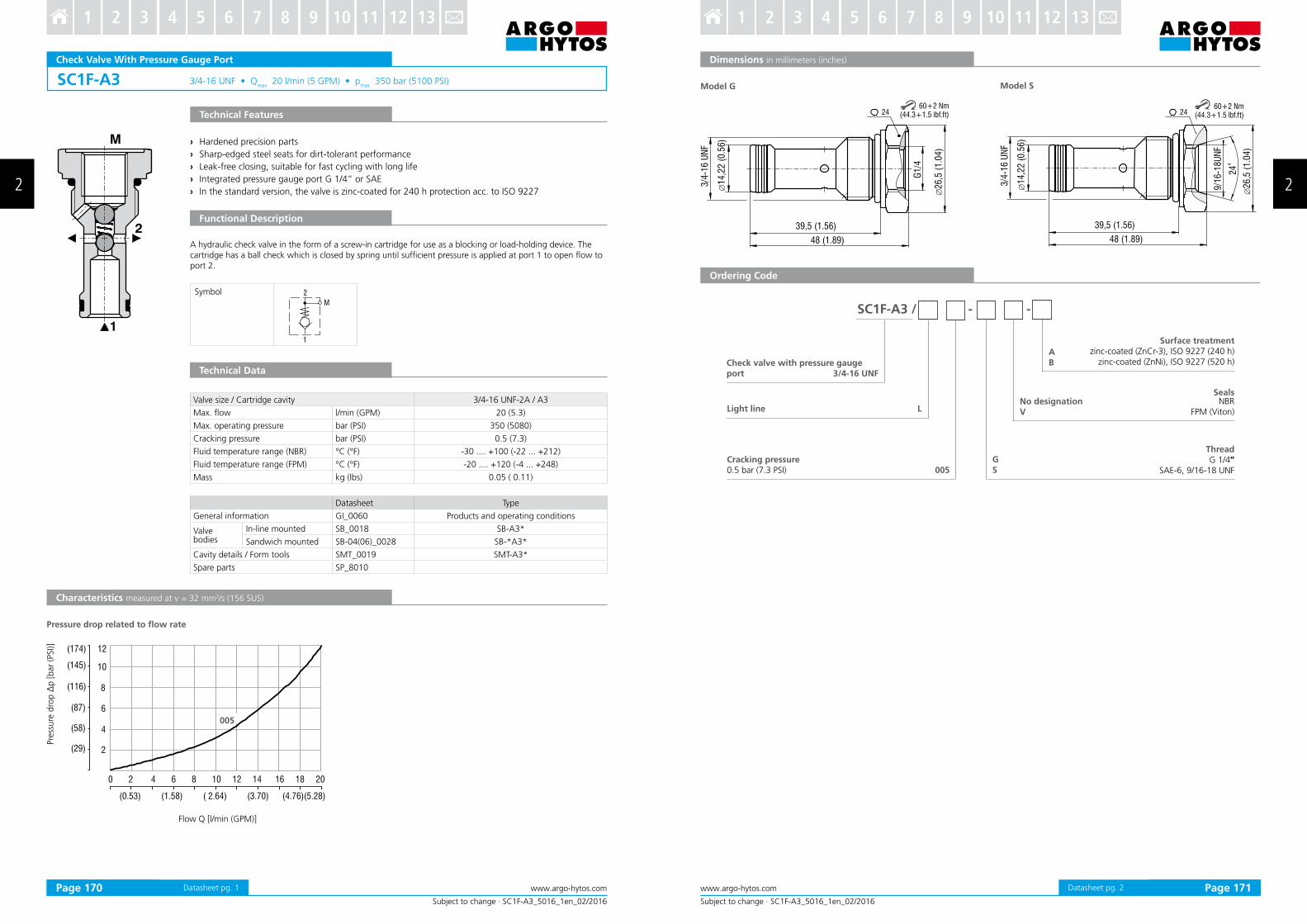
A hydraulic check valve in the form of a screw-in cartridge for use as a blocking or load-holding device. The cartridge has a ball check which is closed by spring until suficient pressure is applied at port 1 to open low to port 2.
Pressure drop related to low rate
Pre
ssure
dro
p ∆
p [bar
(PSI)]
Flow Q [l/min (GPM)]
Valve size / Cartridge cavity 3/4-16 UNF-2A / A3
Max. low l/min (GPM) 20 (5.3)
Max. operating pressure bar (PSI) 350 (5080)
Cracking pressure bar (PSI) 0.5 (7.3)
Fluid temperature range (NBR) °C (°F) -30 .... +100 (-22 ... +212)
Fluid temperature range (FPM) °C (°F) -20 .... +120 (-4 ... +248)
Mass kg (Ibs) 0.05 ( 0.11)
Datasheet Type
General information GI_0060 Products and operating conditions
Valve bodies
In-line mounted SB_0018 SB-A3*
Sandwich mounted SB-04(06)_0028 SB-*A3*
Cavity details / Form tools SMT_0019 SMT-A3*
Spare parts SP_8010
39,5 (1.56)
48 (1.89)
24
�1
4,2
2 (
0.5
6)
3/4
-16
UN
F
G1
/4
�2
6,5
(1
.04
)
24
9/1
6-1
8U
NF
39,5 (1.56)
48 (1.89)
24
�1
4,2
2 (
0.5
6)
3/4
-16
UN
F
�2
6,5
(1
.04
)
60+2 Nm (44.3+1.5 lbf.ft)
60+2 Nm (44.3+1.5 lbf.ft)
SC1F-A3 / - -
GS
LLight line
005
AB
Subject to change · SC1F-A3_5016_1en_02/2016
www.argo-hytos.com Page 2Datasheet pg. 2
Model G Model S
Dimensions in millimeters (inches)
Ordering Code
Check valve with pressure gauge port 3/4-16 UNF
SealsNBR
FPM (Viton)
Cracking pressure0.5 bar (7.3 PSI)
ThreadG 1/4”
SAE-6, 9/16-18 UNF
Surface treatmentzinc-coated (ZnCr-3), ISO 9227 (240 h)
Characteristics measured at ν = 32 mm2/s (156 SUS)
› Hardened precision parts
› Sharp“edged steel seats for dirt“tolerant performance
› Leak“free closing’ suitable for fast cycling with long life
› High low capacity
› Optional bias spring ranges for back“pressure control
› In the standard version’ the valve is zinc“coated for 240 h protection acc” to ISO 9227
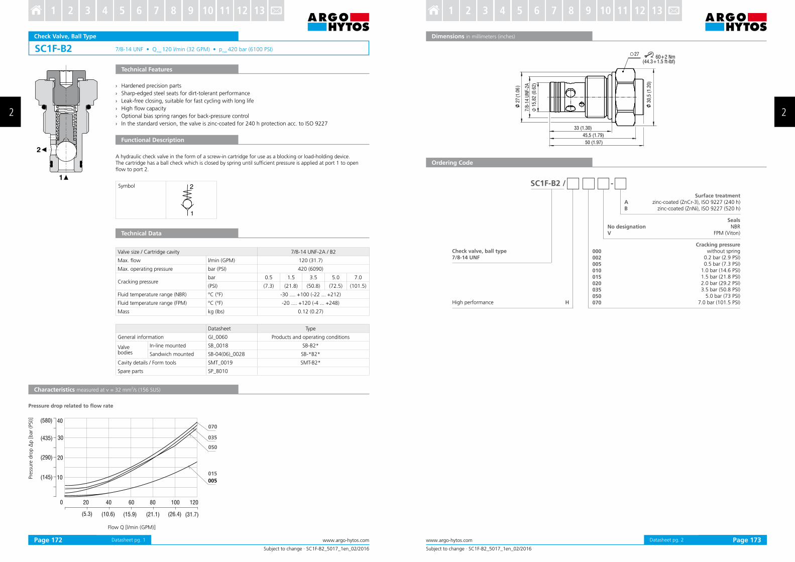
A hydraulic check valve in the form of a screw“in cartridge for use as a blocking or load“holding device” The cartridge has a ball check which is closed by spring until suficient pressure is applied at port 1 to open low to port 2”
Pressure drop related to low rate
Pre
ssure
dro
p ∆
p [bar
(PSI)]
Flow Q [l/min (GPM)]
Technical Data
Valve size / Cartridge cavity 7/8-14 UNF-2A / B2
Max” low l/min (GPM) 120 (31”7)
Max” operating pressure bar (PSI) 420 (6090)
Cracking pressurebar 0”5 1”5 3”5 5”0 7”0
(PSI) (7”3) (21”8) (50”8) (72”5) (101”5)
Fluid temperature range (NBR) °C (°F) “30 ”””” ‘100 (“22 ””” ‘212)
Fluid temperature range (FPM) °C (°F) “20 ”””” ‘120 (“4 ””” ‘248)
Mass kg (Ibs) 0”12 (0”27)
Datasheet Type
General information GI_0060 Products and operating conditions
Valvebodies
In-line mounted SB_0018 SB-B2*
Sandwich mounted SB-04(06)_0028 SB-*B2*
Cavity details / Form tools SMT_0019 SMT-B2*
Spare parts SP_8010
Datasheet pg” 1
45,5 (1.79)
33 (1.30)
50 (1.97)
27
(1.0
6)
7/8
-14
UN
F -2
A
15
,82
(0.6
2)
27
30
,5 (
1.2
0)
60+2 Nm(44.3+1.5 ft-lbf)
Subject to change · SC1F-B2_5017_1en_02/2016
www.argo-hytos.com 2 Page 2
Dimensions in millimeters (inches)
Ordering Code
Check valve, ball type 7/8-14 UNF
SealsNBR
FPM (Viton)
Surface treatmentzinc“coated (ZnCr“3)’ ISO 9227 (240 h)
zinc“coated (ZnNi)’ ISO 9227 (520 h)
No designationV
Cracking pressure without spring
0”2 bar (2”9 PSI)0”5 bar (7”3 PSI)
1”0 bar (14”6 PSI)1”5 bar (21”8 PSI) 2”0 bar (29”2 PSI)3”5 bar (50”8 PSI)
› Poppet type check valve with subplate mounting interface acc. to ISO 4401, DIN 24340 (CETOP 03)
› Sandwich plate design for use in vertical stacking assemblies
› Leak-free closing in one or two service ports , suitable for fast cycling with long life
› Sharp-edged steel seats for dirt-tolerant performance
› High low capacity
› Optional bias spring ranges for back-pressure control
› In the standard version, the valve housing is phosphated and steel parts are zinc-coated for 240 h protection acc. to ISO 9227
Technical Features
Characteristics measured at ν = 32 mm2/s (156 SUS)
Technical Data
Pressure drop related to low rate
Flow Q [l/min (GPM)]
Pre
ssure
dro
p ∆
p [bar
(PSI)]
These check valves in sandwich plate design allow low in one and prevent low in the other direction. The sandwich design enables vertical stacking with other components of the same size. The check valves can be built into one or two channels, the other passages are unobstructed. The cracking pressure depends on the selected bias spring.
Functional Description
Valve size 06 (D03)
Max. low l/min (GPM) 50 (13.2)
Max. operating pressure bar (PSI) 350 (5080)
Cracking pressurebar 0.5 1.5 3 5
(PSI) (7.3) (21.8) (43.5) (72.5)
Fluid temperature range (NBR) °C (°F) -30 .... +100 (-22 ... +212)
Fluid temperature range (FPM) °C (°F) -20 .... +120 (-4 ... +248)
Mass kg (Ibs) 0.8 (1.76)
Datasheet Type
General information GI_0060 Products and operating conditions
Mounting interface / Tolerances SMT_0019 Size 06
Spare parts SP_8010
Symbol
A2 B2
P2
T2
64 (2.52)
6,5
(0.2
6)
11 (0.49)
40 (1.57)
44 (1
.73)
A2 P2 T2 B2
A1 P1 T1 B1
P
A2 P2 T2 B2
A1 P1 T1 B1
T
A2 P2 T2 B2
A1 P1 T1 B1
A
A2 P2 T2 B2
A1 P1 T1 B1
B
A2 P2 T2 B2
A1 P1 T1 B1
C
A2 P2 T2 B2
A1 P1 T1 B1
D
A2 P2 T2 B2
A1 P1 T1 B1
AB
A2 P2 T2 B2
A1 P1 T1 B1
PT
MVJ3-06 - - -
005015030 050
PABTCD
ABPT
Subject to change · MVJ3-06_5018_1en_02/2016
www.argo-hytos.com 2 Page 2Datasheet pg. 2
Dimensions in millimeters (inches)
Ordering Code
Functional Symbols
Note: The orientation of the symbol on the name plate corresponds with the valve function.
valve side
subplate or manifold side
Check valve, poppet type, modular
Valve size
Functional symbolscheck valve in line Pcheck valve in line Acheck valve in line Bcheck valve in line Tcheck valve in line A, invertedcheck valve in line B, invertedcheck valve in line A and Bcheck valve in line P and T
SealsNBR
FPM (Viton)
Cracking pressure0.5 bar ( 7.3 PSI)
1.5 bar ( 21.8 PSI)3.0 bar (43.5 PSI)5.0 bar (72.5 PSI)
Surface treatmentbody phosphated
zinc-coated (ZnCr-3), ISO 9227 (240 h)zinc-coated (ZnNi), ISO 9227 (520 h)
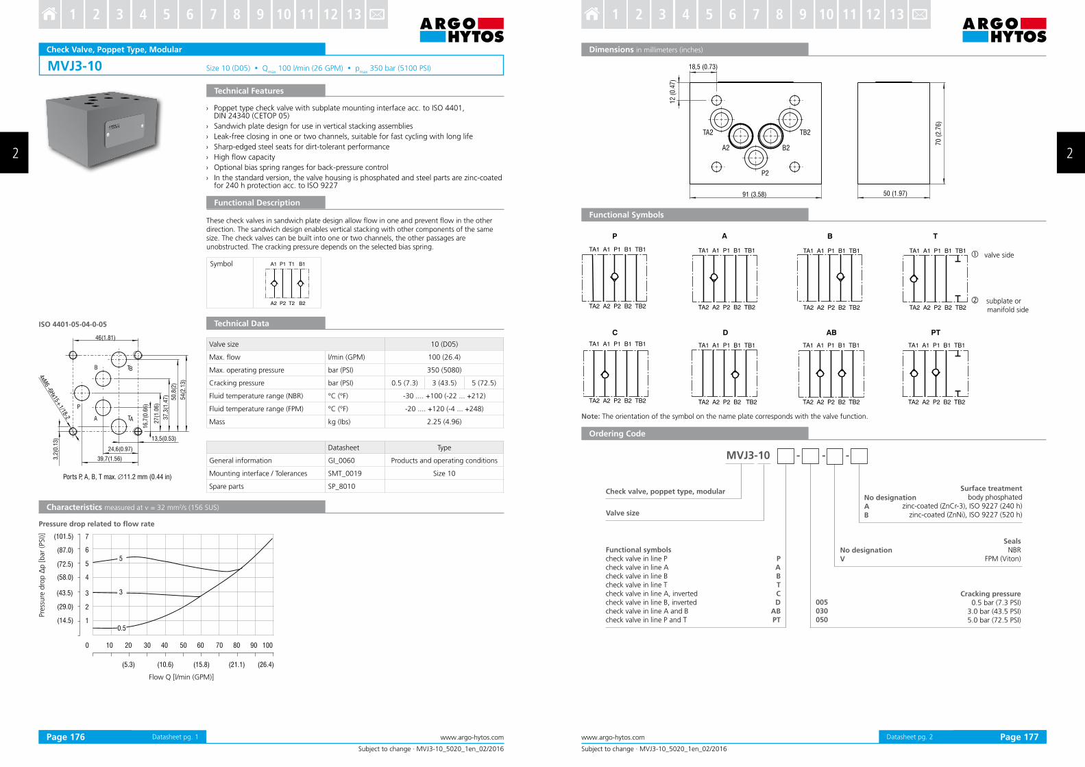
› Poppet type check valve with subplate mounting interface acc. to ISO 4401, DIN 24340 (CETOP 05)
› Sandwich plate design for use in vertical stacking assemblies
› Leak-free closing in one or two channels, suitable for fast cycling with long life
› Sharp-edged steel seats for dirt-tolerant performance
› High low capacity
› Optional bias spring ranges for back-pressure control
› In the standard version, the valve housing is phosphated and steel parts are zinc-coated for 240 h protection acc. to ISO 9227
Technical Features
Characteristics measured at ν = 32 mm2/s (156 SUS)
Technical Data
Pressure drop related to low rate
Flow Q [l/min (GPM)]
Pre
ssure
dro
p ∆
p [bar
(PSI)]
These check valves in sandwich plate design allow low in one and prevent low in the other direction. The sandwich design enables vertical stacking with other components of the same size. The check valves can be built into one or two channels, the other passages are unobstructed. The cracking pressure depends on the selected bias spring.
Functional Description
Valve size 10 (D05)
Max. low l/min (GPM) 100 (26.4)
Max. operating pressure bar (PSI) 350 (5080)
Cracking pressure bar (PSI) 0.5 (7.3) 3 (43.5) 5 (72.5)
Fluid temperature range (NBR) °C (°F) -30 .... +100 (-22 ... +212)
Fluid temperature range (FPM) °C (°F) -20 .... +120 (-4 ... +248)
Mass kg (Ibs) 2.25 (4.96)
Datasheet Type
General information GI_0060 Products and operating conditions
Mounting interface / Tolerances SMT_0019 Size 10
Spare parts SP_8010
Datasheet pg. 1
50 (1.97)
70 (
2.7
6)
91 (3.58)
18,5 (0.73)
12 (
0.4
7)
A2
P2
B2
TB2TA2
P
TA1 A1 P1 B1 TB1
TA2 A2 P2 B2 TB2
A
TA1 A1 P1 B1 TB1
TA2 A2 P2 B2 TB2
B
TA1 A1 P1 B1 TB1
TA2 A2 P2 B2 TB2
C
TA1 A1 P1 B1 TB1
TA2 A2 P2 B2 TB2
D
TA1 A1 P1 B1 TB1
TA2 A2 P2 B2 TB2
AB
TA1 A1 P1 B1 TB1
TA2 A2 P2 B2 TB2
T
TA1 A1 P1 B1 TB1
TA2 A2 P2 B2 TB2
PT
TA1 A1 P1 B1 TB1
TA2 A2 P2 B2 TB2
MVJ3-10 - - -
PABTCD
ABPT
005030050
No designationAB
Subject to change · MVJ3-10_5020_1en_02/2016
www.argo-hytos.com Page 2
Dimensions in millimeters (inches)
valve side
subplate or manifold side
Functional Symbols
Note: The orientation of the symbol on the name plate corresponds with the valve function.
Ordering Code
Check valve, poppet type, modular
Valve size
Functional symbolscheck valve in line Pcheck valve in line Acheck valve in line Bcheck valve in line Tcheck valve in line A, invertedcheck valve in line B, invertedcheck valve in line A and Bcheck valve in line P and T
SealsNBR
FPM (Viton)
Cracking pressure 0.5 bar (7.3 PSI)
3.0 bar (43.5 PSI)5.0 bar (72.5 PSI)
No designationV
Surface treatmentbody phosphated
zinc-coated (ZnCr-3), ISO 9227 (240 h)zinc-coated (ZnNi), ISO 9227 (520 h)
Characteristics measured at ν = 32 mm2/s (156 SUS)
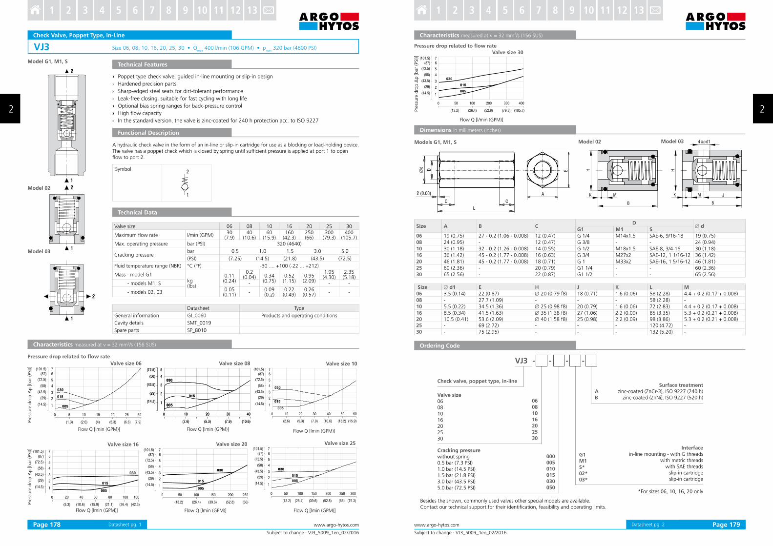
› Poppet type check valve’ guided in“line mounting or slip“in design
› Hardened precision parts
› Sharp“edged steel seats for dirt“tolerant performance
› Leak“free closing’ suitable for fast cycling with long life
› Optional bias spring ranges for back“pressure control
› High low capacity
› In the standard version’ the valve is zinc“coated for 240 h protection acc” to ISO 9227
A hydraulic check valve in the form of an in“line or slip“in cartridge for use as a blocking or load“holding device” The valve has a poppet check which is closed by spring until suficient pressure is applied at port 1 to open low to port 2”
Pressure drop related to low rate
Valve size 06 08 10 16 20 25 30
Maximum low rate l/min (GPM)30
(7”9)40
(10”6)60
(15”9)160
(42”3)250 (66)
300 (79”3)
400 (105”7)
Max” operating pressure bar (PSI) 320 (4640)
Cracking pressurebar 0”5 1”0 1”5 3”0 5”0
(PSI) (7”25) (14”5) (21”8) (43”5) (72”5)
Fluid temperature range (NBR) °C (°F) “30 ”””” ‘100 (“22 ””” ‘212)
Mass “ model G1kg (Ibs)
0”11 (0”24)
0”2 (0”04) 0”34
(0”75)0”52
(1”15)0”95 (2”09)
1”95(4”30)
2”35 (5”18)
“ models M1’ S “ “ “
“ models 02’ 03 0”05 (0”11)
“0”09 (0”2)
0”22 (0”49)
0”26 (0”57)
“ “
Datasheet Type
General information GI_0060 Products and operating conditions
Cavity details SMT_0019
Spare parts SP_8010
Valve size 06
Pre
ssure
dro
p Δ
p [
bar
(PSI)]
Flow Q [lmin (GPM)]
Flow Q [lmin (GPM)]
Flow Q [lmin (GPM)] Flow Q [lmin (GPM)]
Model 02
Model 03
Technical Data
Pre
ssure
dro
p Δ
p [bar
(PSI)]
Valve size 08
Valve size 16
Valve size 10
Valve size 25Valve size 20
Flow Q [lmin (GPM)] Flow Q [lmin (GPM)]
Model G1, M1, S
Symbol
(29)
(43.5)
(14.5)
(87)
(101.5)
(58)
(72.5)
1
2
5
6
3
4
50 100 200 300 400
(13.2) (26.4) (52.8) (79.3) (105.7)
030
005
015
0
7
L
CC
2 (0.08) A
EDd∅
4 x d1∅
H
K JM
B
H
K M
B
VJ3 - - - -
0608
10
16
20
25
30
000
005
010
015
030
050
G1
M1S*
02*
03*
A
B
Subject to change · VJ3_5009_1en_02/2016
www.argo-hytos.com 2 Page 2Datasheet pg” 2
Characteristics measured at ν = 32 mm2/s (156 SUS)
Besides the shown’ commonly used valves other special models are available”Contact our technical support for their identiication’ feasibility and operating limits”
Interfacein“line mounting “ with G threads
with metric threadswith SAE threads
slip“in cartridgeslip“in cartridge
*For sizes 06’ 10’ 16’ 20 only
Check valve, poppet type, in-line
Cracking pressurewithout spring0”5 bar (7”3 PSI)1”0 bar (14”5 PSI)1”5 bar (21”8 PSI)3”0 bar (43”5 PSI)5”0 bar (72”5 PSI)
Valve size06081016202530
Surface treatmentzinc“coated (ZnCr“3)’ ISO 9227 (240 h)
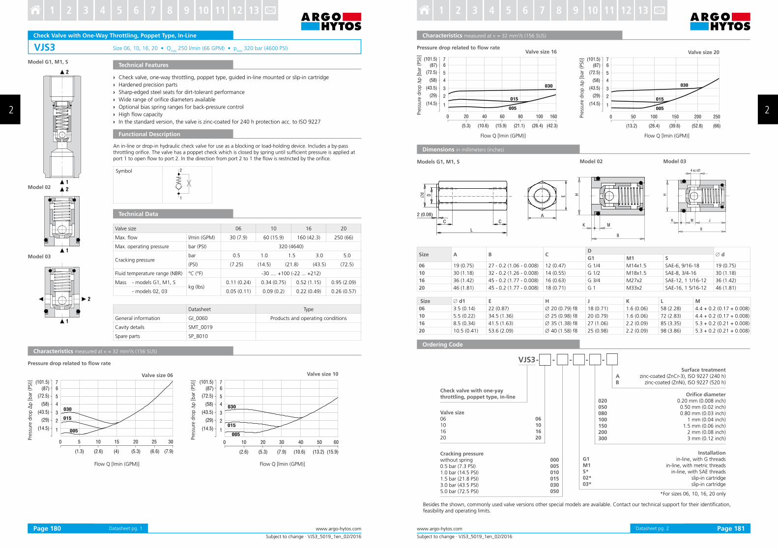
› Sharp“edged steel seats for dirt“tolerant performance
› Wide range of oriice diameters available
› Optional bias spring ranges for back“pressure control
› High low capacity
› In the standard version’ the valve is zinc“coated for 240 h protection acc” to ISO 9227
An in“line or drop“in hydraulic check valve for use as a blocking or load“holding device” Includes a by“pass throttling oriice” The valve has a poppet check which is closed by spring until suficient pressure is applied at port 1 to open low to port 2” In the direction from port 2 to 1 the low is restricted by the oriice”
Besides the shown’ commonly used valve versions other special models are available” Contact our technical support for their identiication’ feasibility and operating limits”
Valve size06101620
Surface treatmentzinc“coated (ZnCr“3)’ ISO 9227 (240 h)
zinc“coated (ZnNi)’ ISO 9227 (520 h)
Characteristics measured at ν = 32 mm2/s (156 SUS)
Pressure drop related to low rateValve size 16 Valve size 20
Pre
ssure
dro
p ∆
p [bar
(PSI)]
Flow Q [lmin (GPM)] Flow Q [lmin (GPM)]
Pre
ssure
dro
p ∆
p [bar
(PSI)]
Installationin-line, with G threads
in-line, with metric threadsin-line, with SAE threads
Characteristics measured at ν = 32 mm2/s (156 SUS)
› Hardened precision parts
› Sharp-edged steel seats for dirt-tolerant performance
› Leak-free closing, suitable for fast cycling with long life
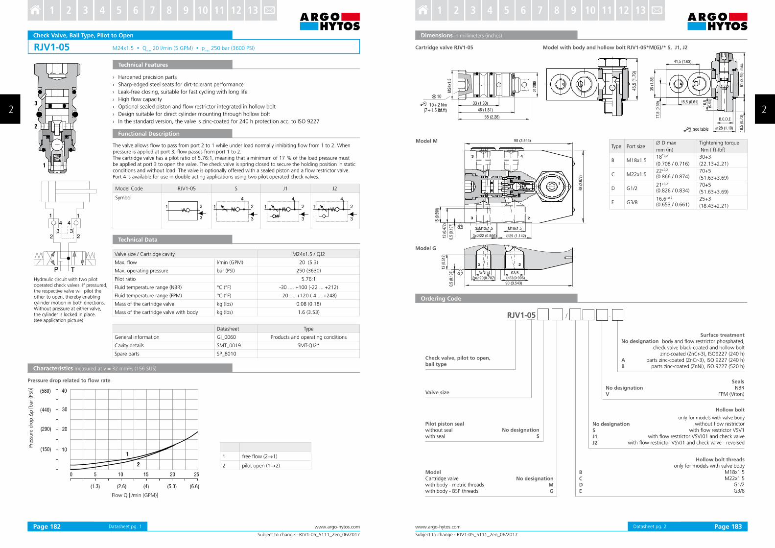
› High low capacity
› Optional sealed piston and low restrictor integrated in hollow bolt
› Design suitable for direct cylinder mounting through hollow bolt
› In the standard version, the valve is zinc-coated for 240 h protection acc. to ISO 9227
The valve allows low to pass from port 2 to 1 while under load normally inhibiting low from 1 to 2. When pressure is applied at port 3, low passes from port 1 to 2.The cartridge valve has a pilot ratio of 5.76:1, meaning that a minimum of 17 % of the load pressure must be applied at port 3 to open the valve. The check valve is spring closed to secure the holding position in static conditions and without load. The valve is optionally offered with a sealed piston and a low restrictor valve. Port 4 is available for use in double acting applications using two pilot operated check valves.
Pre
ssure
dro
p Δ
p [bar
(PSI)]
Flow Q [l/min (GPM)]
Valve size / Cartridge cavity M24x1.5 / QJ2
Max. low l/min (GPM) 20 (5.3)
Max. operating pressure bar (PSI) 250 (3630)
Pilot ratio 5.76:1
Fluid temperature range (NBR) °C (°F) -30 .... +100 (-22 ... +212)
Fluid temperature range (FPM) °C (°F) -20 .... +120 (-4 ... +248)
Mass of the cartridge valve kg (Ibs) 0.08 (0.18)
Mass of the cartridge valve with body kg (Ibs) 1.6 (3.53)
Datasheet Type
General information GI_0060 Products and operating conditions
Cavity details SMT_0019 SMT-QJ2*
Spare parts SP_8010
Pressure drop related to low rate
Hydraulic circuit with two pilot operated check valves. If pressured, the respective valve will pilot the other to open, thereby enabling cylinder motion in both directions. Without pressure at either valve,the cylinder is locked in place.(see application picture)
Model Code RJV1-05 S J1 J2
Symbol
Technical Data
1 free low (2→1)
2 pilot open (1→2)
Datasheet pg. 1
see table
45,5
(1.7
9)
33 (1.30)
46 (1.81)
58 (2.28)
M2
4x1
,5
20
f8
10
∅
∅ 28 (1.10)
15,5 (0.61)
17
,5 (
0.6
9)
18
,5 (
0.7
3)
16
,5(0
.65
)
61
(2
.40
) m
ax.
35
(1
.38
)
B,C,D,E
41,5 (1.63)
10+2 Nm (7+1.5 lbf.ft)
RJV1-05 / -
BC
D
E
Subject to change · RJV1-05_5111_2en_06/2017
www.argo-hytos.com 2 Page 2
Model with body and hollow bolt RJV1-05*M(G)/* S, J1, J2Cartridge valve RJV1-05
Model M
Model G
Type Port size∅ D max Tightening torque
mm (in) Nm ( ft-Ibf)
B M18x1.518
+0,2 30+3
(0.708 / 0.716) (22.13+2.21)
C M22x1.522+0,2 70+5(0.866 / 0.874) (51.63+3.69)
D G1/221+0,2 70+5(0.826 / 0.834) (51.63+3.69)
E G3/816,6+0,2 25+3(0.653 / 0.661) (18.43+2.21)
Dimensions in millimeters (inches)
Ordering Code
Check valve, pilot to open,ball type
Valve size
Pilot piston sealwithout sealwith seal
Hollow bolt threadsonly for models with valve body
M18x1.5M22x1.5
G1/2G3/8
ModelCartridge valvewith body - metric threadswith body - BSP threads
Hollow bolt
only for models with valve body
without low restrictorwith low restrictor VSV1
with low restrictor VSVJ01 and check valvewith low restrictor VSVJ1 and check valve - reversed
No designationV
SealsNBR
FPM (Viton)
No designationSJ1J2
No designation
AB
Surface treatmentbody and low restrictor phosphated,
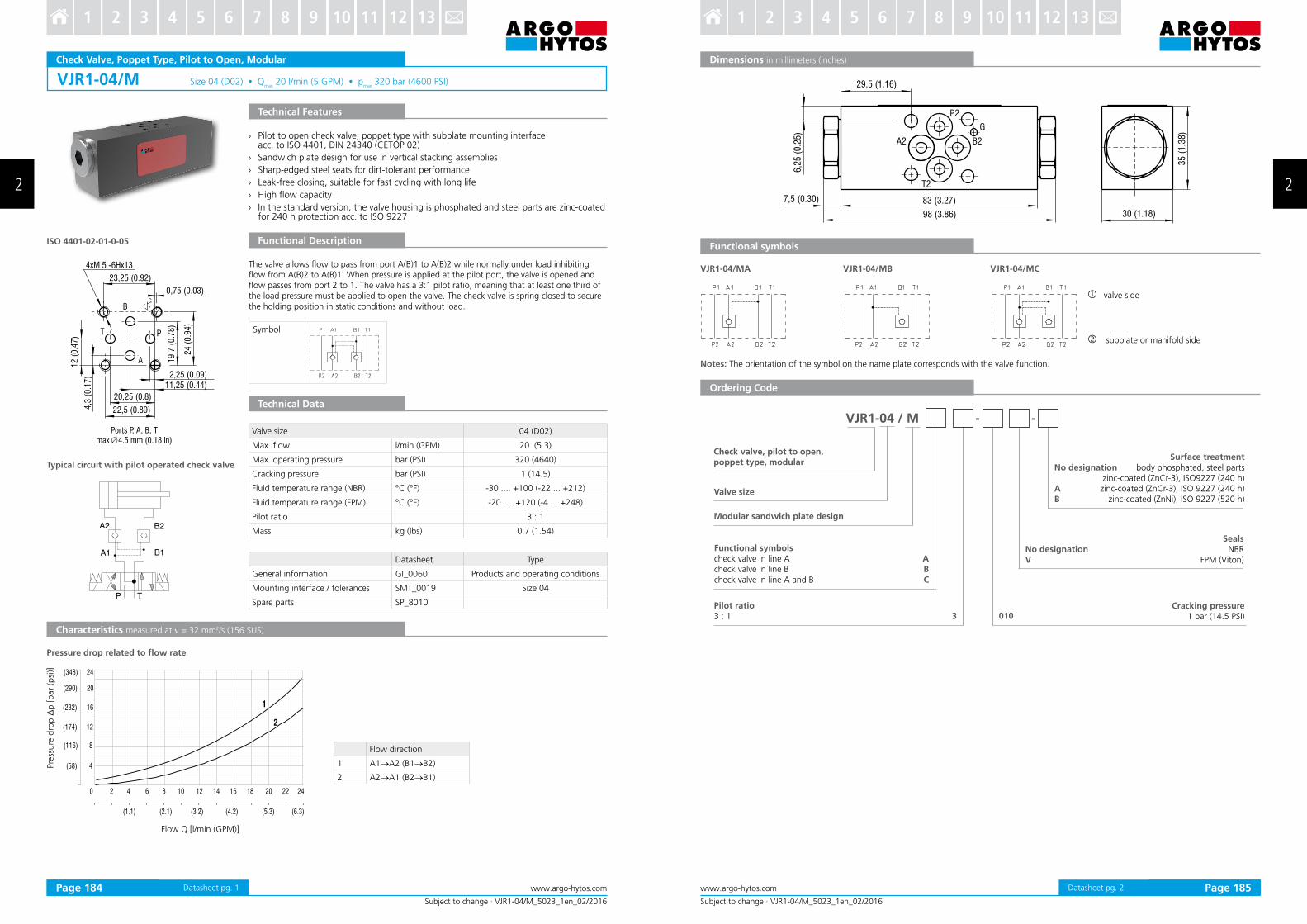
› Pilot to open check valve, poppet type with subplate mounting interface acc. to ISO 4401, DIN 24340 (CETOP 02)
› Sandwich plate design for use in vertical stacking assemblies
› Sharp-edged steel seats for dirt-tolerant performance
› Leak-free closing, suitable for fast cycling with long life
› High low capacity
› In the standard version, the valve housing is phosphated and steel parts are zinc-coated for 240 h protection acc. to ISO 9227
Technical Features
Characteristics measured at ν = 32 mm2/s (156 SUS)
Technical Data
Pressure drop related to low rate
Flow Q [l/min (GPM)]
Pre
ssure
dro
p ∆
p [bar
(psi
)]
Symbol
Typical circuit with pilot operated check valve
The valve allows low to pass from port A(B)1 to A(B)2 while normally under load inhibiting low from A(B)2 to A(B)1. When pressure is applied at the pilot port, the valve is opened and low passes from port 2 to 1. The valve has a 3:1 pilot ratio, meaning that at least one third of the load pressure must be applied to open the valve. The check valve is spring closed to secure the holding position in static conditions and without load.
Functional Description
Valve size 04 (D02)
Max. low l/min (GPM) 20 (5.3)
Max. operating pressure bar (PSI) 320 (4640)
Cracking pressure bar (PSI) 1 (14.5)
Fluid temperature range (NBR) °C (°F) -30 .... +100 (-22 ... +212)
Fluid temperature range (FPM) °C (°F) -20 .... +120 (-4 ... +248)
Pilot ratio 3 : 1
Mass kg (Ibs) 0.7 (1.54)
Datasheet Type
General information GI_0060 Products and operating conditions
Mounting interface / tolerances SMT_0019 Size 04
Spare parts SP_8010
Ports P, A, B, T max ∅4.5 mm (0.18 in)
Flow direction
1 A1→A2 (B1→B2)
2 A2→A1 (B2→B1)
29,5 (1.16)
98 (3.86)
83 (3.27)7,5 (0.30)
6,2
5 (
0.2
5)
35
(1
.38
)
30 (1.18)
B2A2
T2
P2
G
VJR1-04/MA VJR1-04/MB VJR1-04/MC
VJR1-04 / M - -
3
ABC
010
Subject to change · VJR1-04/M_5023_1en_02/2016
www.argo-hytos.com 2 Page 2Datasheet pg. 2
Dimensions in millimeters (inches)
Ordering Code
Functional symbols
Notes: The orientation of the symbol on the name plate corresponds with the valve function.
valve side
subplate or manifold side
Check valve, pilot to open,poppet type, modular
Valve size
Modular sandwich plate design
Functional symbolscheck valve in line Acheck valve in line Bcheck valve in line A and B
Pilot ratio3 : 1
Surface treatmentbody phosphated, steel parts
zinc-coated (ZnCr-3), ISO9227 (240 h)zinc-coated (ZnCr-3), ISO 9227 (240 h)
Characteristics measured at ν = 40 mm2/s (195 SUS)
› Hardened precision parts
› Sharp“edged steel seats for dirt“tolerant performance
› Leak“free closing’ suitable for fast cycling with long life
› High low capacity
› Optional sealed piston
› In the standard version’ the valve is zinc“coated for 240 h protection acc” to ISO 9227
The valve allows low to pass from port 2 to 1 while under load normally inhibiting low from 1 to 2” When pressure is applied at port 3’ low passes from port 1 to 2”The cartridge valve has a pilot ratio of 3:1’ meaning that at least one“third of the load pressure must be applied at port 3 to open the valve” The check valve is spring closed to secure the holding position in static conditions and without load”
Pre
ssure
dro
p ∆
p [bar
(PSI)]
Flow Q [l/min (GPM)]
Valve size / Cartridge cavity M20x1”5 / Q3
Max” low l/min (GPM) 30 (8)
Max” operating pressure bar (PSI) 350 (5080)
Pilot ratio 3:1
Fluid temperature range (NBR) °C (°F) “20 ”””” ‘90 (“4 ””” ‘194)
Mass kg (Ibs) 0.08 (0.18)
Datasheet Type
General information GI_0060 Products and operating conditions
Valve bodiesIn“line mounted SB_0018 SB“Q3*
Sandwich mounted SB“04(06)_0028 SB“*Q3*
Cavity details SMT_0019 SMT“Q3*
Spare parts SP_8010
Technical Data
Pressure drop related to low rate
1 free low (2→1)
2 pilot open (1→2)
Datasheet pg” 1
45+2 Nm
(33+1.5 Ibf.ft)
39,5 (1.56) 7,0 (0.28) MAX
M20x1
,5
24
Subject to change · SC5H-Q3/I_5217_1en_02/2016
www.argo-hytos.com Page 2
Dimensions in millimeters (inches)
Ordering Code
Check valve, pilot to open,poppet type M20x1.5
No designationS
Pilot ratiostandard
Pilot piston sealwithout pilot piston seal
with pilot piston seal
No designation Seals
NBR
Surface treatmentzinc“coated (ZnCr“3)’ ISO 9227 (240 h)
› Pilot to open check valve, poppet type with subplate mounting interface acc. to ISO 4401, DIN 24340 (CETOP 03)
› Sandwich plate design for use in vertical stacking assemblies
› Sharp-edged steel seats for dirt-tolerant performance
› Leak-free closing, suitable for fast cycling with long life
› High low capacity
› Optional bias spring ranges for back-pressure control
› Two pilot ratios available
› In the standard version, the valve housing is phosphated and steel parts are zinc-coated for 240 h protection acc. to ISO 9227
Technical Features
Characteristics measured at ν = 32 mm2/s (156 SUS)
Technical Data
ISO 4401-03-02-0-05
Pressure drop related to low rate
Flow Q [l/min (GPM)]
Pre
ssure
dro
p ∆
p [bar
(PSI)]
The valve allows low to pass from port A(B)1 to A(B)2 while normally closing low from A(B)2 to A(B)1 with load. When pressure is applied at pilot port. The low passes from port 2 to 1.The valve has two pilot ratios option. This requires at least one-third (ratio 3:1) or one-ninth (ratio 9:1) of the load pressure to be applied at the opposite port to open the valve. The check valve is spring closed to secure the holding position in static conditions and without load. The valve is offered with optional bias spring ranges for back-pressure control.
Characteristics measured at ν = 40 mm2/s (195 SUS)
› Hardened precision parts
› Sharp“edged steel seats for dirt“tolerant performance
› Leak“free closing’ suitable for fast cycling with long life
› High low capacity
› Optional sealed piston
› In the standard version’ the valve is zinc“coated for 240 h protection acc” to ISO 9227
Functional Description
The valve allows low to pass from port 2 to 1 while under load normally inhibiting low from 1 to 2” When pressure is applied at port 3’ low passes from port 1 to 2”The cartridge valve has a pilot ratio of 4:1’ meaning at least one fourth of the load pressure must be applied at port 3 to open the valve” The check valve is spring closed to secure the holding position in static conditions and without load”
Pre
ssure
dro
p ∆
p [bar
(PSI)]
Flow Q [l/min (GPM)]
Valve size / Cartridge cavity M27x1.5 / R3
Max” low l/min (GPM) 90 (23.8)
Max” operating pressure bar (PSI) 350 (5080)
Pilot ratio 4:1
Fluid temperature range (NBR) °C (°F) “20 ”””” ‘90 (“4 ””” ‘194)
Mass kg (Ibs) 0.27 (0.60)
Datasheet Type
General information GI_0060 Products and operating conditions
Valve bodies In“line mounted SB_0018 SB“R3*
Cavity details SMT_0019 SMT“R3*
Spare parts SP_8010
Technical Data
Pressure drop related to low rate
1 free low (2→1)
2 pilot open (1→2)
M27
x1,5
51 (2.01) 18,5 (0.73) MAX
32
60+2 Nm
(44+1.5 Ibf.ft)
SC5H-R3/I 4 -
4:1
A
Subject to change · SC5H-R3/I_5218_1en_02/2016
www.argo-hytos.com Page 2Datasheet pg” 2
Dimensions in millimeters (inches)
Ordering Code
Check valve, pilot to open,poppet type M27x1.5
No designationS
Pilot ratiostandard
Optional pilot piston sealwithout seal
with seal
No designation Seals
NBR
Surface treatmentzinc“coated (ZnCr“3)’ ISO 9227 (240 h)
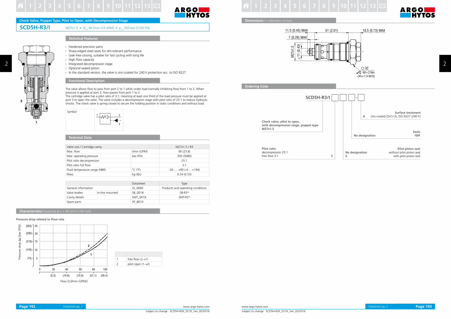
Check Valve, Poppet Type, Pilot to Open, with Decompression Stage
Technical Features
Functional Description
Characteristics measured at ν = 40 mm2/s (195 SUS)
› Hardened precision parts
› Sharp“edged steel seats for dirt“tolerant performance
› Leak“free closing’ suitable for fast cycling with long life
› High low capacity
› Integrated decompression stage
› Optional sealed piston
› In the standard version’ the valve is zinc“coated for 240 h protection acc” to ISO 9227
The valve allows low to pass from port 2 to 1 while under load normally inhibiting low from 1 to 2” When pressure is applied at port 3’ low passes from port 1 to 2”The cartridge valve has a pilot ratio of 3:1’ meaning at least one third of the load pressure must be applied at port 3 to open the valve” The valve includes a decompression stage with pilot ratio of 25:1 to reduce hydraulic shocks” The check valve is spring closed to secure the holding position in static conditions and without load”
Pre
ssure
dro
p ∆
p [bar
(PSI)]
Flow Q [l/min (GPM)]
Valve size / Cartridge cavity M27x1.5 / R3
Max” low l/min (GPM) 90 (23.8)
Max” operating pressure bar (PSI) 350 (5080)
Pilot ratio decompression 25:1
Pilot ratio full low 3:1
Fluid temperature range (NBR) °C (°F) “20 ”””” ‘90 (“4 ””” ‘194)
Mass kg (Ibs) 0.24 (0.53)
Datasheet Type
General information GI_0060 Products and operating conditions
Valve bodies In“line mounted SB_0018 SB“R3*
Cavity details SMT_0019 SMT“R3*
Spare parts SP_8010
Technical Data
Pressure drop related to low rate
1 free low (2→1)
2 pilot open (1→2)
60+2 Nm(44+1.5 Ibf.ft)
11.5 (0.45) MAX
7 (0.28) MAX
51 (2.01) 18.5 (0.73) MAX
32
M2
7x1
,5
�1
1 (
0.4
3)
3
A
SCD5H-R3/I -
Subject to change · SCD5H-R3/I_5219_1en_02/2016
www.argo-hytos.com Page 2Datasheet pg” 2
Dimensions in millimeters (inches)
Ordering Code
Check valve, pilot to open,with decompression stage, poppet typeM27x1.5
No designationS
Pilot ratiodecompression 25:1free low 3:1
Pilot piston sealwithout pilot piston seal
with pilot piston seal
No designation Seals
NBR
Surface treatmentzinc“coated (ZnCr“3)’ ISO 9227 (240 h)
Pilot to Open Operated Check Valve, Poppet Type, Modular
› Pilot to open operated check valve, poppet type with subplate mounting surface acc. to ISO 4401, DIN 24340 (CETOP 05) standards
› Sandwich plate design for use in vertical stacking assemblies
› Sharp-edged ground steel seats for for dirt-tolerant performance
› Leak-free closing and suitable for fast cycling with long life
› High low capacity
› Valve is itted with decompression stage facilitating steady opening without pressure peaks
› In the standard version, the valve housing is phosphated and steel parts zinc coated for 240 h protection acc. to ISO 9227
Technical Features
Characteristics measured at ν = 32 mm2/s (156 SUS)
Technical Data
ISO 4401-05-04-0-05
Pressure drop related to low rate
Flow Q [l/min (GPM)]
Pre
ssure
dro
p ∆
p [bar
(PSI)]
Typical circuit with pilot operated check valve
The valve allows low to pass from port A(B)1 to A(B)2 while normally closing low from A(B)2 to A(B)1 with load. When pressure is applied at pilot port. The low passes from port 2 to 1.The valve has a 6:1 pilot ratio. The check valve is also spring closed to secure holding position in static conditions without the load. The valve is offered with optional bias spring ranges for back-pressure control.
Functional Description
Valve size 10 (D05)
Max. low l/min (GPM) 140 (37)
Max. operating pressure bar (PSI) 350 (5080)
Cracking pressure bar (PSI) 2 (29)
Fluid temperature range (NBR) °C (°F) -30 .... +100 (-22 ... +212)
Fluid temperature range (FPM) °C (°F) -20 .... +120 (-4 ... +248)
Pilot ratio 6:1
Weight kg (Ibs) 2.2 (4.85)
Datasheet Type
General information GI_0060 products and operating conditions
Mounting interface / tolerances SMT_0019 Size 10
Spare parts SP_8010
Ports P, A, B, T - max. ∅11,2 mm (0.44 in)
Flow direction
1 A1→A2 (B1→B2)
2 A2→A1 (B2→B1)
Datasheet pg. 1
P
B
TBTA
A
24,6
(0.9
7)
28 (1.1)
110 (4.33)
69,5
(2.7
4)
10,5 (0.41)
50 (1.97)
VJR3-10/MA VJR3-10/MB VJR3-10/MC
VJR3-10 / M - -
Model ”C„
ABC
0206
Subject to change · VJR3-10/M_5035_1en_05/2017
www.argo-hytos.com Page 2
Dimensions in millimeters (inches)
Ordering Code
Functional symbols
Check valve, pilot to open,poppet type, modular
SealsNBR
FPM (Viton)
Valve size
Modular sandwich plate design
Functional symbolsCheck valve in line ACheck valve in line BCheck valve in line A and B
Notes: The orientation of the symbol on the name plate corresponds with the valve function.
No designationV
Cracking pressure2.0 bar (29 PSI)
Pilot ratio6:1
Surface treatmentbody phosphated, steel parts
zinc-coated (ZnCr-3), ISO9227 (240 h)zinc-coated (ZnCr-3), ISO 9227 (240 h)
Characteristics measured at ν = 40 mm2/s (195 SUS)
› Hardened precision parts
› Sharp“edged steel seats for dirt“tolerant performance
› Leak“free closing’ suitable for fast cycling with long life
› High low capacity
› Optional external pilot port
› Optional sealed piston
› In the standard version’ the valve is zinc“coated for 240 h protection acc” to ISO 9227
The valve allows low to pass from port 2 to 1 while under load normally inhibiting low from 1 to 2”When pressure is applied at port 3’ low passes from port 1 to 2”The cartridge valve has a pilot ratio of 3:1’ meaning at least one third of the load pressure must be applied at port 3 to open the valve” The check valve is spring closed to secure the holding position in static conditions and without load”
Characteristics measured at ν = 40 mm2/s (195 SUS)
› Hardened precision parts
› Sharp“edged steel seats for dirt“tolerant performance
› Leak“free closing’ suitable for fast cycling with long life
› High low capacity
› In the standard version’ the valve is zinc“coated for 240 h protection acc” to ISO 9227
The valve allows low to pass from port 1 to 2 while normally inhibiting low from 2 to 1 under load” When pressure is applied at port 3’ the poppet locks the ball valve in place’ inhibiting low from port 1 to 2”The cartridge valve has a 2:1 pilot ratio” The check valve is spring closed to secure the holding position in static conditions and without load”
Pre
ssure
dro
p ∆
p [
bar
(PSI)]
Flow Q [l/min (GPM)]
Valve size / Cartridge cavity M20x1”5 / Q3
Max” low l/min (GPM) 30 (8)
Max” operating pressure bar (PSI) 350 (5080)
Pilot ratio 2:1
Fluid temperature range (NBR) °C (°F) “20 ”””” ‘90 (“4 ””” ‘194)
Mass kg (Ibs) 0.08 (0.18)
Datasheet Type
General information GI_0060 Products and operating conditions
Valve bodiesIn“line mounted SB_0018 SB“Q3*
Sandwich mounted SB“04(06)_0028 SB“*Q3*
Cavity details SMT_0019 SMT“Q3*
Spare parts SP_8010
Technical Data
Pressure drop related to low rate
1 Free low (1→2)
7 (0.28) MAX39.5 (1.56)
M20x1
,5
24
45+2 Nm
(33+1.5 Ibf.ft)
A
2:1
SCC5H-Q3/I 2 -
Subject to change · SCC5H-Q3/I_5221_1en_02/2016
www.argo-hytos.com Page 2Datasheet pg” 2
Dimensions in millimeters (inches)
Ordering Code
Check valve, pilot to close,poppet type M20x1.5
SealsNBR
Pilot ratiostandard No designation
Surface treatmentzinc“coated (ZnCr“3)’ ISO 9227 (240 h)
Characteristics measured at ν = 40 mm2/s (195 SUS)
› Hardened precision parts
› Sharp“edged steel seats for dirt“tolerant performance
› Leak“free closing’ suitable for fast cycling with long life
› High low capacity
› In the standard version’ the valve is zinc“coated for 240 h protection acc” to ISO 9227
The valve allows low to pass from port 1 to 2 while normally inhibiting low from 2 to 1 under load” When pressure is applied at port 3’ the poppet locks the ball valve in place’ inhibiting low from port 1 to 2”The cartridge valve has a 2:1 pilot ratio” The check valve is spring closed to secure the holding position in static conditions and without load”