16
CAT.ES100-42 B Series ZSE30/ISE30 2-Color Display Type High-Precision Digital Pressure Switch Improved, easy-to-read 2-color display

CAT.ES100-42 B
Series ZSE30/ISE30
2-Color Display TypeHigh-Precision Digital Pressure Switch
Improved, easy-to-read 2-color display

Features 1
Abnormal conditions can be detected at a glance!
SET
kPaPRESSURE
OUT
SET
kPaPRESSURE
OUT
SET
kPaPRESSURE
OUT
SET
kPaPRESSURE
OUT
SET
kPaPRESSURE
OUT
2-color digital display allows you to choosethe setting according to your application requirements.
4 different display settings are available.
Series ZSE30/ISE30 Series ZSE30/ISE30
2-Color Display TypeHigh-Precision Digital Pressure Switch
This photo shows 2 display colors simultaneously for product presentation purposes. In actual application, only one color is displayed at a time.

Features 2
This function allows uniformity in the numbers displayed.
Vacuum/Low pressure (ZSE30) Positive pressure (ISE30)
Blue Gray
High-precisionresolution: 1/1000
Switches for vacuum and positivepressure can be easily distinguished.The different display panel frame colors easily tell them apart.
Variations
In addition to the conventional voltage output type (1 to 5V)
Current output type (4 to 20mA) is now available.
• Convenient when longer wiring is required• Excellent noise resistance
Applicablepanel thickness is up to 6mm.(Panel mounting)
With analog output
Display calibration
Old Model
New Model
Rated pressurerange
Setting/Display resolution 0.2kPa 0.001MPa
OutputSwitch output
Analog output
NPN/PNP open collector (1 output)
Voltage output: 1 to 5V; Current output: 4 to 20mA
45mA or less (70mA or less for current output)
Panel mount/Bracket
Current consumption
Option
Vacuum/Low pressureZSE30
Positive pressureISE30
100kPa
–100kPa
0
1MPa
0
More user-friendly controls
103.5
34
.5
Compact profile
Plug-type connectors take the burden out of wiring work and maintenance.
Raised rubber button controls are clearly set apart, simple to operate, soft to the touch.
Series ZSE30/ISE30
Space-saving improvementEconomical use of space
Old ModelZSE4EISE4E
New ModelZSE30ISE30
Each display required its own panel opening.
126
40
Just one panel opening isrequired for stackable displays, which can be mounted either horizontally or vertically.

1
2-Color Display TypeHigh-Precision Digital Pressure Switch
Series ZSE30/ISE30How to Order
Optional Part Nos.
Option Part no.
ZS-27-A
ZS-27-B
ZS-27-C
Note
Lead wire length: 2mWith mounting screws
(M3 x 5L: 2 pcs.)
Lead wire with connector
Bracket
Panel mount adapter
ZSE30 01
ISE30 01
25 M
25 M
For vacuum/Low pressure
For positive pressure
Unit specificationNilM
With unit switching functionFixed SI unitI (International System of Units) Note)
NPN outputPNP output
1 to 5V output4 to 20mA output
25652628
Option 2Nil
A
NoneBracket
B
Panel mount
Without lead wire
Lead wire with connector(Lead wire length: 2m)
Option 1
Nil
L
R 1/8 (with M5 female thread)NPT 1/8 (with M5 female thread)
01T1
Piping specification
Note) Fixed units: For vacuum/Low pressure: kPAFor positive pressure: MPa
When optional parts are required separately, use the following part numbers to place an order.
Output specification

2
2-Color Display TypeHigh-Precision Digital Pressure Switch Series ZSE30/ISE30
Specifications
Rated pressure rangeRegulating pressure rangeProof pressureSetting/Display resolutionFluidPower supply voltageCurrent consumptionSwitch output Note 1)
Repeatability
Analogoutput
Hysteresis
Display
Display accuracyIndication lightTemperature characteristicsEnclosure
Ambient temperature range
Ambient humidity rangeWithstand voltageInsulation resistanceVibration resistanceImpact resistancePort size
Material
Weight
Max. load currentMax. applied voltageResidual voltageResponse timeShort circuit protection
Voltage output
Current output
Hysteresis modeWindow comparator mode
ZSE30–100 to 100kPa–101 to 101kPa
500kPa0.2kPa
ISE300 to 1MPa
–0.1 to 1MPa1.5MPa
0.001MPaAir, Inert gas, Non-flammable gas
12 to 24VDC ±10%, Ripple (p-p) 10% or less (with power supply polarity protection)45mA or less (70mA or less for current output)
NPN or PNP open collector output: 1 output80mA
30V (with NPN output)1V or less (with load current of 80mA)
2.5ms or less (Response time selections with anti-chattering function: 20ms, 160ms, 640ms, 1280ms)With short circuit protection
±0.2% F.S. ±2 digits or less ±0.2% F.S. ±1 digit or less
Output voltage: 1 to 5V ±2.5% F.S. or less (with rated pressure range)Linearity: ±1% F.S. or less; Output impedance: Approx. 1kΩ
Output current: 4 to 20mA; ±2.5% F.S. or less (with rated pressure range)Linearity: ±1% F.S. or less
Maximum load impedance: 300Ω with power supply voltage of 12V;600Ω with power supply voltage of 24V
Minimum load impedance: 50Ω
Variable
3 1/2-digit, 7-segment indicator, 2-color display (red and green)Sampling cycle: 5 times/s
±2% F.S. ±2 digits (25°C) ±2% F.S. ±1 digit (25°C)Lights up when output is ON (Green)
±2% F.S. or less (based on 25°C)
IP40Operating: 0° to 50°C; Stored: –10° to 60°C
(with no freezing or condensation)
Operating and stored: 35 to 85% RH (with no condensation)1000VAC for 1 min. between live parts and enclosure
50MΩ or more between live parts and enclosure (at 500VDC)10 to 150Hz, 1.5mm amplitude in X, Y, Z directions for 2 hours each
100m/s2 in X, Y, Z directions 3 times each01 type: R 1/8, M5 x 0.8; T1 type: NPT 1/8, M5 x 0.8
Front case: PBT; Rear case: PBT; Piping port: C3602 (electroless nickel plated)Sensor pressure: Silicon; O-ring: NBR
43g (without lead wire)
Note 3)
Note 1) When switch output is selected, analog output is not available.
Note 2) When voltage output is selected, a simultaneous selection of switch output and current output is not available.
Note 3) When current output is selected, a simultaneous selection of switch output and voltage output is not available.
Note 2)
3
Series ZSE30/ISE30
(Standard: Factory setting) (Reversed) (Standard: Factory setting) (Reversed)
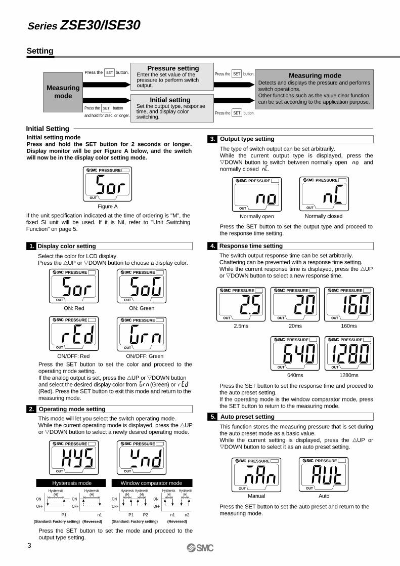
Setting
Initial Setting
Measuringmode
Initial setting
Pressure settingMeasuring mode
Initial setting modePress and hold the SET button for 2 seconds or longer. Display monitor will be per Figure A below, and the switch will now be in the display color setting mode.
If the unit specification indicated at the time of ordering is "M", the fixed SI unit will be used. If it is Nil, refer to "Unit Switching Function" on page 5.
The switch output response time can be set arbitrarily.Chattering can be prevented with a response time setting.While the current response time is displayed, press the UP or DOWN button to select a new response time.
This function stores the measuring pressure that is set during the auto preset mode as a basic value.While the current setting is displayed, press the UP or DOWN button to select it as an auto preset setting.
Press the SET button to set the response time and proceed to the auto preset setting.If the operating mode is the window comparator mode, press the SET button to return to the measuring mode.
The type of switch output can be set arbitrarily.While the current output type is displayed, press the DOWN button to switch between normally open and normally closed .PRESSURE
OUT
Figure A
PRESSURE
OUT
ON: Red
This mode will let you select the switch operating mode.While the current operating mode is displayed, press the UP or DOWN button to select a newly desired operating mode.
Select the color for LCD display.Press the UP or DOWN button to choose a display color.
Press the SET button to set the color and proceed to the operating mode setting.If the analog output is set, press the UP or DOWN button and select the desired display color from (Green) or (Red). Press the SET button to exit this mode and return to the measuring mode.
PRESSURE
OUT
PRESSURE
OUT
PRESSURE
OUT
ON: Green
ON/OFF: Red ON/OFF: Green
PRESSURE
OUT
PRESSURE
OUT
Hysteresis mode Window comparator mode
Normally open Normally closed
PRESSURE
OUT
PRESSURE
OUT
PRESSURE
OUT
PRESSURE
OUT
PRESSURE
OUT
PRESSURE
OUT
PRESSURE
OUT
2.5ms 20ms 160ms
640ms 1280ms
PRESSURE
OUT
PRESSURE
OUT
Manual Auto
Press the SET button.
ON
OFF
Hysteresis(H)
P1
ON
OFF
n1
Hysteresis(H)
ON
OFF
P2P1
Hysteresis(H)
Hysteresis(H)
ON
OFF
n2n1
Hysteresis(H)
Hysteresis(H)
Press the SET button.
Press the SET button.Press the SET button
and hold for 2sec. or longer.
Enter the set value of the pressure to perform switch output.
Set the output type, response time, and display color switching.
Detects and displays the pressure and performs switch operations.Other functions such as the value clear functioncan be set according to the application purpose.
Press the SET button to set the output type and proceed to the response time setting.
3. Output type setting
4. Response time setting
5. Auto preset setting
Press the SET button to set the auto preset and return to the measuring mode.
1. Display color setting
2. Operating mode setting
Press the SET button to set the mode and proceed to the output type setting.

4
Pressure settingManual setting
Press the SET button in the measuring mode to display the set value. and the current set value blink alternately.
Press the SET button to display the next set value. Press the UP or DOWN button to change the value. (Refer to "How to Set Value" on the lower right hand corner of this page.)
Hysteresis modeIn this mode, hysteresis (H) and the set value for hysteresis are displayed alternately after setting P1. Press the SET button to return to the normal measuring mode. Press the UP or DOWN button to change the value.(Refer to "How to Set Value" below right.)
Window comparator modeIn this mode, P2 and the current set value are displayed alternately after setting P1. Press the SET button to display the next set value ( : hysteresis). Press the UP or DOWN button to change the value.(Refer to "How to Set Value" at right.)
Next, and the set vale for hysteresis will be displayed alternately. Press the SET button to return to the normal measuring mode. Press the UP or DOWN button to change the value.(Refer to "How to Set Value" at right.)
1. Auto preset preparation modeWhile in the measuring mode, press the SET button to activate the auto preset preparation mode, and will be displayed. Proceed to prepare the devices to perform the pressure setting. While is still displayed, press both the UP and DOWN buttons simultaneously to return to the measuring mode.
2. Auto preset settingPress the SET button to activate the mode to execute auto preset functions. When is displayed, start the system operation and change the pressure. The set value will be automatically detected and stored.While is still displayed, press the SET button to complete the setting and return to the normal measuring mode.
PRESSURE
OUT
Alternatelydisplayed
PRESSURE
OUT
Normally Open
Normally Closed
PRESSURE
OUT
PRESSURE
OUT
PRESSURE
OUT
1. Press the UP or DOWN button to change the set value. The first digit blinks.
2. Press the UP or DOWN button to set the value arbitrarily. (If there is no button operation for more than 10 seconds, the current value will be automatically set and the function will return to the set value display mode.)
3. With every push of the SET button, the next (higher) digit blinks.
When the left-most digit is zero, " " or " " will blink.If the SET button is pressed while the left-most digit is blinking, the right-most digit will now blink.
4. Press and hold the SET button for 1 second or longer to return to the set value display mode.
How to Set ValueTo enter a value such as the one for pressure setting:
1st digit
2nd digit 3rd digit
Auto preset setting
Pressure set value can be verified without holding or stopping the switch output operation.
2-Color Display TypeHigh-Precision Digital Pressure Switch Series ZSE30/ISE30

5
0 Applied pressure +
: Factory setting display valueset prior to shipment
: Display calibration range
±5% R.D.(±2.5% R.D.)
Dis
play
ed p
ress
ure
valu
eSetting
Function setting Display calibration
During measuring mode, press the SET and DOWN buttons simultaneously and hold for 2 seconds or longer. and current measured value will be displayed.Press the UP or DOWN button to change the set value. If there is no button operation for more than 2 seconds after changing the set value, the display mode returns to displaying and the current measured value.
Press the SET button to display the adjusted value (percent).The adjusted value and will be alternately displayed.
Peak/Bottom hold functionThis function constantly detects and updates the maximum and minimum pressure values and allows to hold the display value.To use a peak hold function, press and hold the UP button for 1 second or longer. The maximum pressure value is held and blinks repeatedly. Press and hold the UP button again for 1 second or longer to release this function and return to the measuring mode.To use a bottom hold function, press the DOWN button for 1 second or longer. The minimum pressure value is held and blinks repeatedly. Press and hold DOWN button again for 1 second or longer to release this function and return to the measuring mode.
Key lock functionThis function prevents incorrect operations such as changing the set value accidentally. Press the SET button and hold for 4 seconds or longer to display the current or setting. Press the UP or DOWN button to select the setting and set this function with the SET button. Use the mode to avoid accidental button operation. To release a key lock function, press the SET button and hold for 4 seconds or longer to display the current setting, and select the mode.
Zero out (Zero ADJ) functionThis function clears and resets the displayed value as long as the measuring pressure is within ±70 digits of the atmospheric pressure.(Due to individual product differences, the setting range varies ±10% F.S.)This function is effective in detecting pressure fluctuations that exceed a certain amount without being affected by the supply pressure. Press and hold the UP and DOWN buttons simultaneously to reset the display. Release the buttons to return to the measuring mode.
Press the SET button to return to the normal measuring mode.
Alternatelydisplayed
Alternatelydisplayed
PRESSURE
OUT
PRESSURE
OUT
PRESSURE
OUT
PRESSURE
OUT
PRESSURE
OUT
For vacuum/low pressure Pa⇔kgf/cm2⇔bar⇔psi⇔inchHg⇔mmHgFor positive pressure MPa⇔kgf/cm2⇔bar⇔psi
Current measured value
Adjusted value(Percent)
+
Lock
Selection of lock and unlock
Unlock
Press the SET button
and hold for 4 sec.
or longer
SET
Displayed unitsPakgf/cm²
barpsimmHginchHg
ISE300.001MPa
0.010.010.2——
ZSE300.2kPa0.0020.0020.05
20.2
Indication of units
This function eliminates slight differences in the output values and allows uniformity in the numbers displayed.Displayed values of the pressure sensor can be calibrated to within ±5% for Series ISE and ±2.5% for Series ZSE.
Note) When the display calibration function is used, the regulating pressure value may change ±1 digit.
Press and hold for 1 second or longer.
Mea
surin
g m
ode
Mea
surin
g m
ode
Mea
surin
g m
ode
When not selecting "M" for unit specificationDesired display unit can be selected.Press the UP or DOWN button to switch the unit, and the set value is automatically converted.The conversion order is: PA⇔GF⇔bAr⇔PSi⇔inH⇔mmHPress the SET button to set the unit and proceed to the display color setting.
Unit Conversion Function
Series ZSE30/ISE30
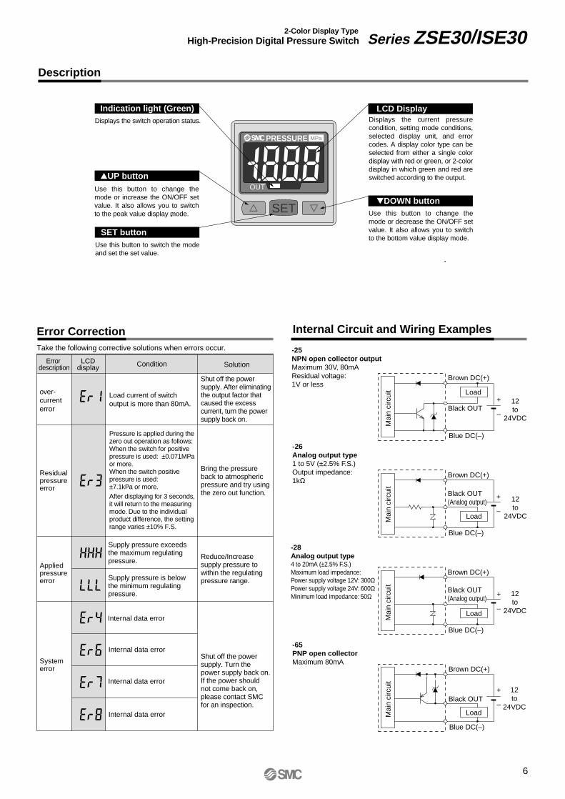
Error description
over-currenterror
Residualpressureerror
Appliedpressureerror
Systemerror
LCDdisplay Condition Solution
Take the following corrective solutions when errors occur.
Load current of switch output is more than 80mA.
Pressure is applied during the zero out operation as follows: When the switch for positive pressure is used: ±0.071MPa or more.When the switch positive pressure is used:±7.1kPa or more.After displaying for 3 seconds, it will return to the measuring mode. Due to the individual product difference, the setting range varies ±10% F.S.
Supply pressure exceeds the maximum regulating pressure.
Supply pressure is below the minimum regulating pressure.
Shut off the power supply. After eliminating the output factor that caused the excess current, turn the power supply back on.
Bring the pressure back to atmospheric pressure and try using the zero out function.
Reduce/Increase supply pressure to within the regulating pressure range.
Shut off the power supply. Turn the power supply back on.If the power should not come back on, please contact SMC for an inspection.
SET
MPaPRESSURE
OUT
6
Description
Error Correction Internal Circuit and Wiring Examples
Indication light (Green) LCD Display
DOWN button
Displays the switch operation status.
UP button
SET button
-25NPN open collector outputMaximum 30V, 80mAResidual voltage: 1V or less
-26Analog output type1 to 5V (±2.5% F.S.)Output impedance:1kΩ
-28Analog output type4 to 20mA (±2.5% F.S.)Maximum load impedance:Power supply voltage 12V: 300ΩPower supply voltage 24V: 600ΩMinimum load impedance: 50Ω
-65PNP open collectorMaximum 80mA
+
–
+
–
+
–
+
–Load
Brown DC(+)
Black OUT
Blue DC(–)
Load
Brown DC(+)
Black OUT(Analog output)
Blue DC(–)
Mai
n ci
rcui
t
Load
Brown DC(+)
Black OUT(Analog output)
Blue DC(–)
Brown DC(+)
Black OUT
Blue DC(–)
Load12to
24VDC
Displays the current pressure condition, setting mode conditions, selected display unit, and error codes. A display color type can be selected from either a single color display with red or green, or 2-color display in which green and red are switched according to the output.
Use this button to change the mode or increase the ON/OFF set value. It also allows you to switch to the peak value display mode.
Use this button to switch the mode and set the set value.
Use this button to change the mode or decrease the ON/OFF set value. It also allows you to switch to the bottom value display mode.
Mai
n ci
rcui
tM
ain
circ
uit
Mai
n ci
rcui
t
2-Color Display TypeHigh-Precision Digital Pressure Switch Series ZSE30/ISE30
Internal data error
Internal data error
Internal data error
Internal data error
12to
24VDC
12to
24VDC
12to
24VDC

7
SET
MPaPRESSURE
OUT
Series ZSE30/ISE30
Dimensions
SM
C
1.5
Width across flats 12
83.6
9.525
10
30
20 ±
0.1
20 ±0.1
01: R 1/8T1: NPT 1/8
2-M3 x 0.5Thread depth 4
Lead wirewith connector
M5 x 0.8
With bracket
Panel mount
20
20
30
35 35
1.8
45
42.5
10
3
22
15
4.2
SM
C
25
30
R 4.5R 4.5
34.5 47.8
21
MADE IN JAPAN
817.87.2
8.75
9.5
Panel thickness 0.5 to 6
SET
MPaPRESSURE
OUT

SET
MPaPRESSURE
OUT
SET
MPaPRESSURE
OUT
SET
MPaPRESSURE
OUT
SET
MPaPRESSURE
OUT
SET
MPaPRESSURE
OUT
SET
MPaPRESSURE
OUT
8
Dimensions
Panel fitting dimension
MADE IN JAPAN
MADE IN JAPAN
MADE IN JAPANMADE IN JAPAN
MADE IN JAPAN
MADE IN JAPAN
31 x n pcs. + 3.5 x (n pcs. – 1)
3124
and
up
0–0.431 24 and up
31 x
n p
cs. +
3.5
x (
n pc
s. –
1)
0–0.4
0–
0.4
31
1-pc. mounting Multiple (2 pcs. or more) horizontal mounting
Multiple (2 pcs. or more) vertical mounting
2-Color Display TypeHigh-Precision Digital Pressure Switch Series ZSE30/ISE30

Series ZSE30/ISE30
Safety Instructions
Note 1) ISO 4414: Pneumatic fluid power -- Recommendations for the application of equipment to transmission and controlsystems
Note 2) JIS B 8370: General Rules for Pneumatic Equipment
Warning
Caution : Operator error could result in injury or equipment damage.
Warning : Operator error could result in serious injury or loss of life.
Danger : In extreme conditions, there is a possible result of serious injury or loss of life.
These safety instructions are intended to prevent a hazardous situation and/or equipment damage. These instructions indicate the level of potential hazard by a label of "Caution", "Warning", or "Danger". To ensure safety, be sure to observe ISO 4414 Note 1), JIS B 8370 Note 2) and other safety practices.
1. The compatibility of pneumatic equipment is the responsibility of the person who designs the pneumatic system or decides its specifications.Since the products specified here are used in various operating conditions, their compatibility with the specific pneumatic system must be based on specifications or after analysis and/or tests to meet your specific requirements.
2. Only trained personnel should operate pneumatically operated machinery and equipment.Compressed air can be dangerous if handled incorrectly. Assembly, handling or maintenance of pneumatic systems should be performed by trained and experienced operators.
3. Do not service machinery/equipment or attempt to remove components until safety is confirmed.1. Inspection and maintenance of machinery/equipment should only be performed after confirmation of
safe locked-out control positions.2. When equipment is to be removed, confirm the safety process as mentioned above. Cut the supply
pressure for this equipment and exhaust all residual compressed air in the system.3. Before machinery/equipment is restarted, take measures to prevent shooting-out of cylinder piston
rod, etc. (Bleed air into the system gradually to create back pressure.)
4. Contact SMC if the product is to be used in any of the following conditions:1. Conditions and environments beyond the given specifications, or if product is used outdoors.2. Installation on equipment in conjunction with atomic energy, railway, air navigation, vehicles, medical
equipment, food and beverages, recreation equipment, emergency stop circuits, press applications, or safety equipment.
3. An application which has the possibility of having negative effects on people, property, or animals, and therefore requires special safety analysis.
9
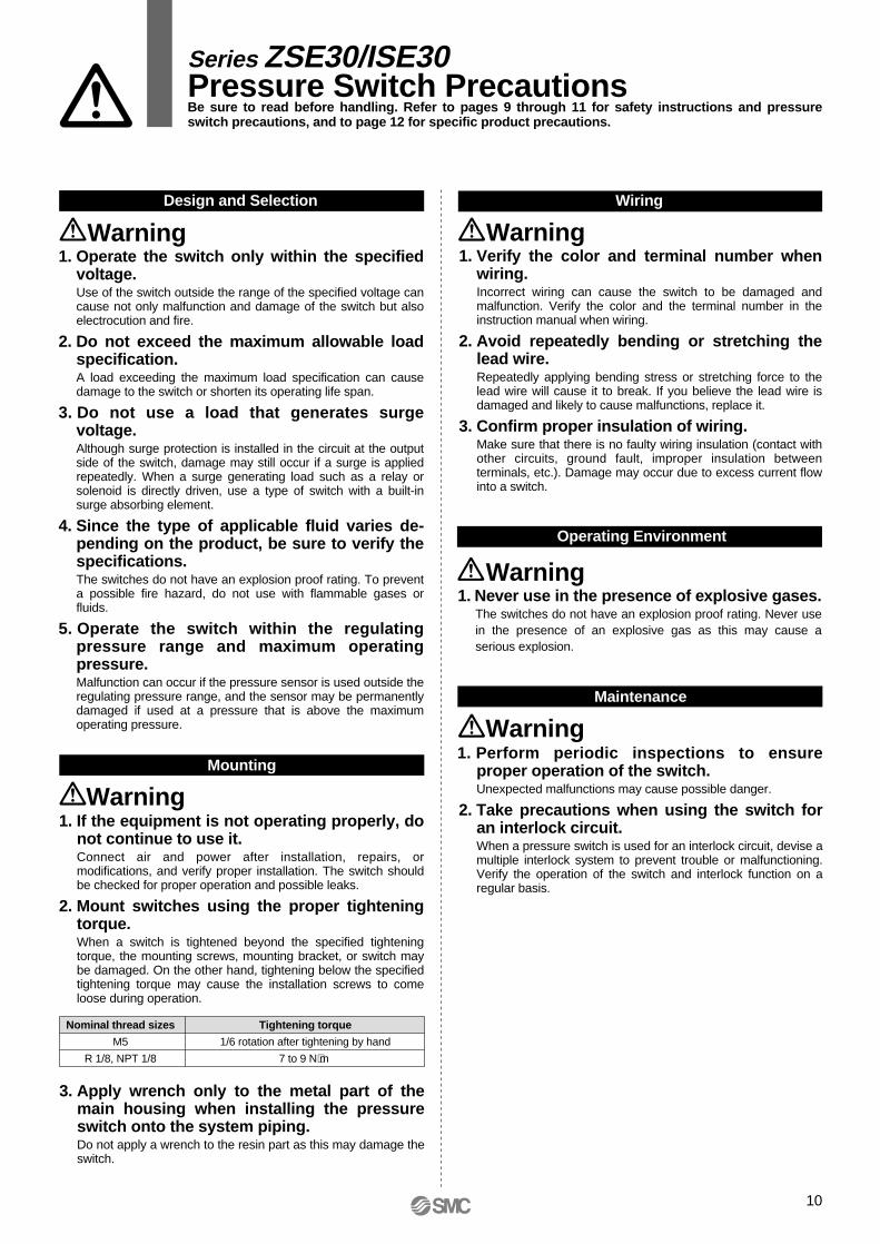
1. Operate the switch only within the specified voltage.Use of the switch outside the range of the specified voltage can cause not only malfunction and damage of the switch but also electrocution and fire.
2. Do not exceed the maximum allowable load specification.A load exceeding the maximum load specification can cause damage to the switch or shorten its operating life span.
3. Do not use a load that generates surge voltage.Although surge protection is installed in the circuit at the output side of the switch, damage may still occur if a surge is applied repeatedly. When a surge generating load such as a relay or solenoid is directly driven, use a type of switch with a built-in surge absorbing element.
4. Since the type of applicable fluid varies de-pending on the product, be sure to verify the specifications.The switches do not have an explosion proof rating. To prevent a possible fire hazard, do not use with flammable gases or fluids.
5. Operate the switch within the regulating pressure range and maximum operating pressure.Malfunction can occur if the pressure sensor is used outside the regulating pressure range, and the sensor may be permanently damaged if used at a pressure that is above the maximum operating pressure.
1. Perform periodic inspections to ensure proper operation of the switch.Unexpected malfunctions may cause possible danger.
2. Take precautions when using the switch for an interlock circuit.When a pressure switch is used for an interlock circuit, devise a multiple interlock system to prevent trouble or malfunctioning. Verify the operation of the switch and interlock function on a regular basis.
Warning Warning
Warning
1. If the equipment is not operating properly, do not continue to use it.Connect air and power after installation, repairs, or modifications, and verify proper installation. The switch should be checked for proper operation and possible leaks.
2. Mount switches using the proper tightening torque.When a switch is tightened beyond the specified tightening torque, the mounting screws, mounting bracket, or switch may be damaged. On the other hand, tightening below the specified tightening torque may cause the installation screws to come loose during operation.
Warning
3. Apply wrench only to the metal part of the main housing when installing the pressure switch onto the system piping.Do not apply a wrench to the resin part as this may damage the switch.
1. Never use in the presence of explosive gases.The switches do not have an explosion proof rating. Never use in the presence of an explosive gas as this may cause a serious explosion.
Warning
Design and Selection Wiring
Operating Environment
Mounting
Maintenance
1. Verify the color and terminal number when wiring.Incorrect wiring can cause the switch to be damaged and malfunction. Verify the color and the terminal number in the instruction manual when wiring.
2. Avoid repeatedly bending or stretching the lead wire.Repeatedly applying bending stress or stretching force to the lead wire will cause it to break. If you believe the lead wire is damaged and likely to cause malfunctions, replace it.
3. Confirm proper insulation of wiring.Make sure that there is no faulty wiring insulation (contact with other circuits, ground fault, improper insulation between terminals, etc.). Damage may occur due to excess current flow into a switch.
Nominal thread sizes
M5
R 1/8, NPT 1/8
Tightening torque
1/6 rotation after tightening by hand
7 to 9 N⋅m
10
Series ZSE30/ISE30 Pressure Switch PrecautionsBe sure to read before handling. Refer to pages 9 through 11 for safety instructions and pressure switch precautions, and to page 12 for specific product precautions.
11
Selection
Warning
Mounting
Warning
Wiring
Warning
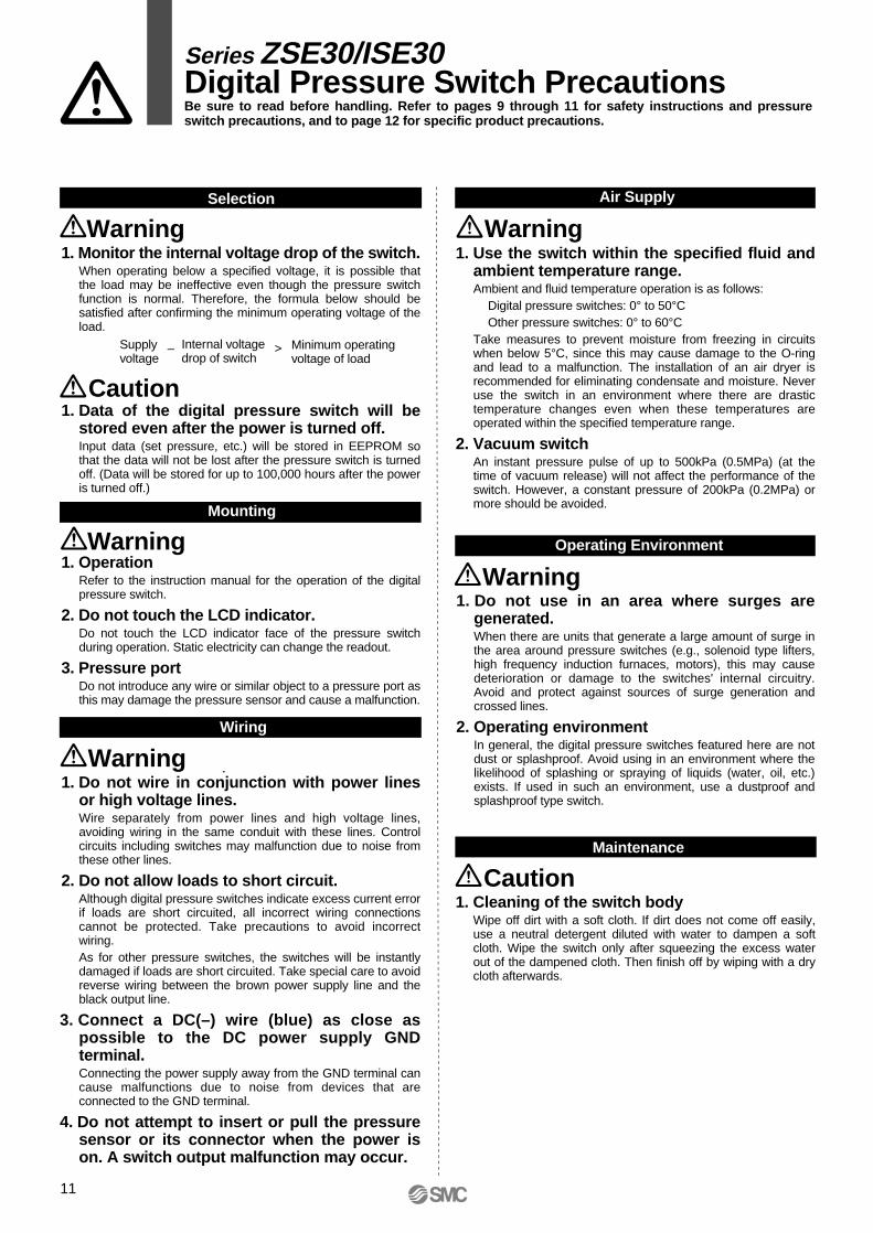
1. Monitor the internal voltage drop of the switch.When operating below a specified voltage, it is possible that the load may be ineffective even though the pressure switch function is normal. Therefore, the formula below should be satisfied after confirming the minimum operating voltage of the load.
1. Data of the digital pressure switch will be stored even after the power is turned off.Input data (set pressure, etc.) will be stored in EEPROM so that the data will not be lost after the pressure switch is turned off. (Data will be stored for up to 100,000 hours after the power is turned off.)
1. OperationRefer to the instruction manual for the operation of the digital pressure switch.
2. Do not touch the LCD indicator.Do not touch the LCD indicator face of the pressure switch during operation. Static electricity can change the readout.
3. Pressure portDo not introduce any wire or similar object to a pressure port as this may damage the pressure sensor and cause a malfunction.
1. Do not wire in conjunction with power lines or high voltage lines.Wire separately from power lines and high voltage lines, avoiding wiring in the same conduit with these lines. Control circuits including switches may malfunction due to noise from these other lines.
2. Do not allow loads to short circuit.Although digital pressure switches indicate excess current error if loads are short circuited, all incorrect wiring connections cannot be protected. Take precautions to avoid incorrect wiring.As for other pressure switches, the switches will be instantly damaged if loads are short circuited. Take special care to avoid reverse wiring between the brown power supply line and the black output line.
3. Connect a DC(–) wire (blue) as close as possible to the DC power supply GND terminal.Connecting the power supply away from the GND terminal can cause malfunctions due to noise from devices that are connected to the GND terminal.
4. Do not attempt to insert or pull the pressure sensor or its connector when the power is on. A switch output malfunction may occur.
Caution
1. Use the switch within the specified fluid and ambient temperature range.Ambient and fluid temperature operation is as follows:
Digital pressure switches: 0° to 50°COther pressure switches: 0° to 60°C
Take measures to prevent moisture from freezing in circuits when below 5°C, since this may cause damage to the O-ring and lead to a malfunction. The installation of an air dryer is recommended for eliminating condensate and moisture. Never use the switch in an environment where there are drastic temperature changes even when these temperatures are operated within the specified temperature range.
2. Vacuum switchAn instant pressure pulse of up to 500kPa (0.5MPa) (at the time of vacuum release) will not affect the performance of the switch. However, a constant pressure of 200kPa (0.2MPa) or more should be avoided.
WarningAir Supply
1. Do not use in an area where surges are generated.When there are units that generate a large amount of surge in the area around pressure switches (e.g., solenoid type lifters, high frequency induction furnaces, motors), this may cause deterioration or damage to the switches' internal circuitry. Avoid and protect against sources of surge generation and crossed lines.
2. Operating environmentIn general, the digital pressure switches featured here are not dust or splashproof. Avoid using in an environment where the likelihood of splashing or spraying of liquids (water, oil, etc.) exists. If used in such an environment, use a dustproof and splashproof type switch.
Operating Environment
Warning
1. Cleaning of the switch bodyWipe off dirt with a soft cloth. If dirt does not come off easily, use a neutral detergent diluted with water to dampen a soft cloth. Wipe the switch only after squeezing the excess water out of the dampened cloth. Then finish off by wiping with a dry cloth afterwards.
Maintenance
Caution
Supplyvoltage
– >Internal voltagedrop of switch
Minimum operatingvoltage of load
Series ZSE30/ISE30 Digital Pressure Switch PrecautionsBe sure to read before handling. Refer to pages 9 through 11 for safety instructions and pressure switch precautions, and to page 12 for specific product precautions.
1. Do not drop, bump, or apply excessive im-pacts (980m/s₂) while handling. Although the body of the sensor may not be damaged, the internal parts of the sensor could be dam-aged and lead to a malfunction.
2. The tensile strength of the cord is 35N. Apply-ing a greater pulling force on it can cause a malfunction. When handling, hold the body of the sensor––do not dangle it from the cord.
3. Do not exceed the screw-in torque of 7 to 9 N⋅m when installing piping. Exceeding this value may cause malfunctioning of the sen-sor.
4. Do not use pressure sensors with corrosive and/or flammable gases or liquids.
WarningHandling
12
1. Incorrect wiring can damage the switch and cause a malfunction or erroneous switch out-put. Connections should be done while the power is turned off.
2. Do not attempt to insert or pull the pressure sensor or its connector when the power is on. A switch output malfunction may occur.
3. Wire separately from power lines and high voltage lines, avoiding wiring in the same conduit with these lines. Malfunctions may occur due to noise from these other lines.
4. If a commercial switching regulator is used, make sure that the F.G. terminal is grounded.
Connection
Warning
1. Our pressure switches are CE marked; however, they are not equipped with surge protection against lightning. Lightning surge countermeasures should be applied directly to system components as necessary.
2. Our pressure switches do not have an explosion proof rating. Never use in the presence of an explosive gas as this may cause a serious explosion.
Operating Environment
Warning
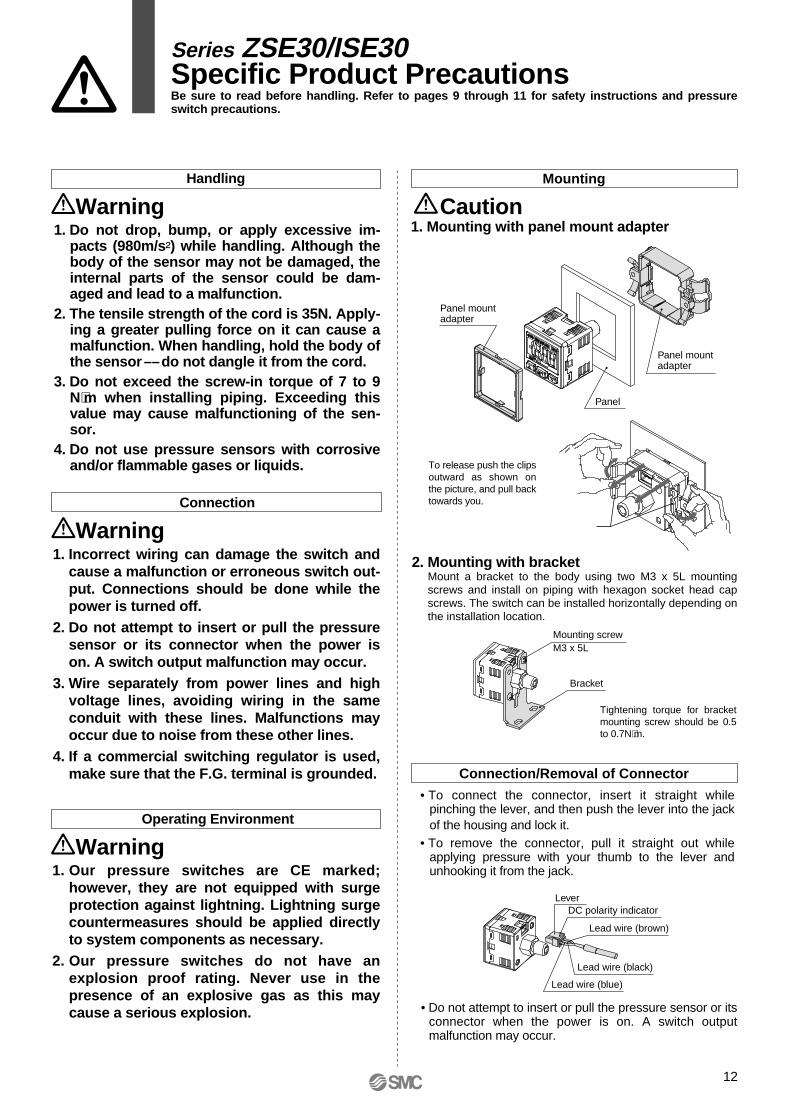
1. Mounting with panel mount adapter
2. Mounting with bracketMount a bracket to the body using two M3 x 5L mounting screws and install on piping with hexagon socket head cap screws. The switch can be installed horizontally depending on the installation location.
CautionMounting
• To connect the connector, insert it straight while pinching the lever, and then push the lever into the jack of the housing and lock it.
• To remove the connector, pull it straight out while applying pressure with your thumb to the lever and unhooking it from the jack.
• Do not attempt to insert or pull the pressure sensor or its connector when the power is on. A switch output malfunction may occur.
Connection/Removal of Connector
Panel mountadapter
Mounting screwM3 x 5L
Bracket
Lever
Lead wire (brown)
DC polarity indicator
Panel
Panel mountadapter
Tightening torque for bracket mounting screw should be 0.5 to 0.7N⋅m.
Lead wire (black)
Lead wire (blue)
Series ZSE30/ISE30Specific Product PrecautionsBe sure to read before handling. Refer to pages 9 through 11 for safety instructions and pressure switch precautions.
To release push the clips outward as shown on the picture, and pull back towards you.
EUROPESLOVENIASMC Industrijska Avtomatika d.o.o.
SPAIN/PORTUGALSMC España, S.A.
SWEDENSMC Pneumatics Sweden AB
SWITZERLANDSMC Pneumatik AG.
UKSMC Pneumatics (U.K.) Ltd.
ASIACHINASMC (China) Co., Ltd.
HONG KONGSMC Pneumatics (Hong Kong) Ltd.
INDIASMC Pneumatics (India) Pvt. Ltd.
MALAYSIASMC Malaysia (S.E.A.) Sdn. Bhd.
PHILIPPINESSMC Pneumatics (Philippines), Inc.
SINGAPORESMC Pneumatics (S.E.A.) Pte. Ltd.SOUTH KOREASMC Pneumatics Korea Co., Ltd.
TAIWANSMC Pneumatics (Taiwan) Co., Ltd.
THAILANDSMC Thailand Ltd.
NORTH AMERICACANADASMC Pneumatics (Canada) Ltd.
MEXICOSMC Corporation (Mexico) S.A. de C.V.USASMC Corporation of America
SOUTH AMERICAARGENTINASMC Argentina S.A.
BOLIVIASMC Pneumatics Bolivia S.R.L.
BRAZILSMC Pneumaticos Do Brazil Ltda.
CHILESMC Pneumatics (Chile) S.A.
VENEZUELASMC Neumatica Venezuela S.A.
OCEANIAAUSTRALIASMC Pneumatics (Australia) Pty. Ltd.
NEW ZEALANDSMC Pneumatics (N.Z.) Ltd.
EUROPEAUSTRIASMC Pneumatik GmbH
CZECHSMC Industrial Automation CZ s.r.o.
DENMARKSMC Pneumatik A/S
FINLANDSMC Pneumatics Finland Oy
FRANCESMC Pneumatique SA
GERMANYSMC Pneumatik GmbH
HUNGARYSMC Hungary Ipari Automatizálási Kft.
IRELANDSMC Pneumatics (Ireland) Ltd.
ITALYSMC Italia S.p.A.
NETHERLANDSSMC Pnuematics BV.
NORWAYSMC Pneumatics Norway A/S
POLANDSMC Industrial Automation Polska Sp.z.o.o.
ROMANIASMC Romania s.r.l.
RUSSIA SMC Pneumatik LLC.
SLOVAKIASMC Priemyselná automatizáciá, s.r.o.
SMC'S GLOBAL MANUFACTURING, DISTRIBUTION AND SERVICE NETWORK
1-16-4 Shimbashi, Minato-ku, Tokyo 105-0004, JAPANTel: 03-3502-2740 Fax: 03-3508-2480URL http://www.smcworld.com© 2001 SMC CORPORATION All Rights Reserved
1st printing September, 2001 D-SMC.L.A. P-80 (YG)This catalog is printed on recycled paper with concern for the global environment.
All specifications in this catalog are subject to change without notice.Printed in Japan.


