MFE 3004 Mechatronics I Designing Mechatronic Systems C. Pace 2.1 MFE 3004 Mechatronics I 2. Designing Mechatronic Systems 2.1 Introduction The design of systems is concerned with the process of taking a customer requirement or need and translating it into a feasible and practical concept design. The initial phases are vital in the design process of any product since errors committed here are difficult to identify until the product is in the hands of the customer. With the need to maintain a competitive edge mainly through better product performance, which in most cases results in higher system complexity, a quality product definition is becoming increasingly important. When an incorrect approach is taken to the design and development of such systems, time over-runs, over-cost, unreliability and failures result, leading to the lack of customer satisfaction. Such failures clearly outline the need to take a correct approach to the design of such complex products by viewing them from a ‘systems’ viewpoint, in order that the complexity can be understood and communicated. The beauty of a systems approach is that it provides a powerful framework for understanding complexity by allowing different engineering disciplines to be portrayed together. Considering the example of the vehicle system mentioned earlier on, the mechanical elements, sensor interfacing, software and microprocessor, interfacing to actuators and the actuators themselves, including various engineering fields and all must cooperate and collaborate if the final product is to be successful. This section delves into the aspects of design that are of primary concern for an engineer designing mechatronic products. A better understanding of a system’s approach is initially taken. This is followed by a brief review of design models adapted for mechatronic products and processes. An insight into aspects of software design, a fundamental element in the design of any mechatronic product, is also given. The relation between mechatronics and concurrent engineering is then depicted, indicated that they are central elements to the philosophy of integrated product development. Since requirements specification and a clear definition of such requirements is of fundamental importance in the design of such complex systems, a review of one technique for mostly handling information requirements will be illustrated towards the end of this chapter. 2.2 Definition of a System from a Mechatronic Perspective There are many definitions of what constitutes a system. A system may be defined as an assembly of components, connected together in an organised way. The components are affected by being part of the system and themselves affect the behaviour of the system. Furthermore, the organisation of the components is expected to do something that the simple sum of the individual components is not capable of doing.
Transcript
MFE 3004 Mechatronics I Designing Mechatronic Systems
C. Pace 2.1
MFE 3004 Mechatronics I
2. Designing Mechatronic Systems
2.1 Introduction The design of systems is concerned with the process of taking a customer requirement or need and translating it into a feasible and practical concept design. The initial phases are vital in the design process of any product since errors committed here are difficult to identify until the product is in the hands of the customer. With the need to maintain a competitive edge mainly through better product performance, which in most cases results in higher system complexity, a quality product definition is becoming increasingly important. When an incorrect approach is taken to the design and development of such systems, time over-runs, over-cost, unreliability and failures result, leading to the lack of customer satisfaction. Such failures clearly outline the need to take a correct approach to the design of such complex products by viewing them from a ‘systems’ viewpoint, in order that the complexity can be understood and communicated. The beauty of a systems approach is that it provides a powerful framework for understanding complexity by allowing different engineering disciplines to be portrayed together. Considering the example of the vehicle system mentioned earlier on, the mechanical elements, sensor interfacing, software and microprocessor, interfacing to actuators and the actuators themselves, including various engineering fields and all must cooperate and collaborate if the final product is to be successful. This section delves into the aspects of design that are of primary concern for an engineer designing mechatronic products. A better understanding of a system’s approach is initially taken. This is followed by a brief review of design models adapted for mechatronic products and processes. An insight into aspects of software design, a fundamental element in the design of any mechatronic product, is also given. The relation between mechatronics and concurrent engineering is then depicted, indicated that they are central elements to the philosophy of integrated product development. Since requirements specification and a clear definition of such requirements is of fundamental importance in the design of such complex systems, a review of one technique for mostly handling information requirements will be illustrated towards the end of this chapter. 2.2 Definition of a System from a
Mechatronic Perspective There are many definitions of what constitutes a system. A system may be defined as an assembly of components, connected together in an organised way. The components are affected by being part of the system and themselves affect the behaviour of the system. Furthermore, the organisation of the components is expected to do something that the simple sum of the individual components is not capable of doing.
MFE 3004 Mechatronics I Designing Mechatronic Systems
C. Pace 2.2
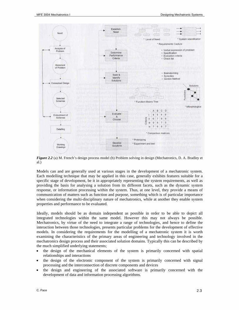
From a mechatronic engineering viewpoint, a system may also be considered to a transformer, which transforms a particular system input into a particular system output (figure 2.1). The inputs and outputs can be either physical (occurring in the energy domain of the system), or information based (occurring in the information domain of the system). The term ‘system’ further emphasises the fact that an overall view is being taken as opposed to a collection of pieces, i.e. for the whole to work the elements must cooperate and do so in a most efficient manner. (Such elements may also include the human being and the external environment). Figure 2.1 A system as a transformer of Inputs to Outputs The examination of any system will show it to be made up of smaller systems, i.e. components that fulfil the system definition. Also any system will be a sub-system of a larger system. This concept helps us to simplify complex systems through the idea of abstraction and information hiding. Abstraction and information hiding simplify the problem of defining and developing a system by allowing for the problem to be broken down into sub-problems. This is provided by the ability to identify only what is useful for the problem at hand, ignoring peripheral information not relevant to the sub-problem (information hiding), and working at a level of detail suitable for the management of the problem (abstraction). This form of representation of systems will be used throughout this chapter, to ensure the avoidance of subdividing systems by their technology rather by their system - sub-system components. 2.3 The Engineering Design Process The Engineering design process may be considered as a goal-oriented problem-solving exercise which has as its objective the conversion of a need, often expressed in the first instance as an abstract concept in terms of general functionality, into a product. Figure 2.2 indicates a basic design process framework suggested by M. French, together with the typical problem solving stages and example techniques used at each stage. Other design process frameworks have been developed which take into consideration several factors of interest. 2.3.1 Modelling as Part of the Design Process The scope of designing a mechatronic system should lie in the ability of the designer to derive an optimal design through the appropriate integration of the various fields and technologies that constitute a mechatronic system. To be able to develop such an optimal design there is the requirement for a sufficient understanding of each of the underlying technologies, thus providing the ability to determine which part of the overall system design problem can best be solved by each of the individual technologies and domains. In order to achieve such an understanding, one must have the ability to model the problem in such a manner that aids in a fuller and more comprehensive understanding of the problem through appropriate analysis, from which potential solutions can be evaluated.
SYSTEM Inputs Outputs
MFE 3004 Mechatronics I Designing Mechatronic Systems
C. Pace 2.3
Figure 2.2 (a) M. French’s design process model (b) Problem solving in design (Mechatronics, D. A. Bradley et al.) Models can and are generally used at various stages in the development of a mechatronic system. Each modelling technique that may be applied in this case, generally exhibits features suitable for a specific stage of development, be it in appropriately representing the system requirements, as well as providing the basis for analysing a solution from its different facets, such as the dynamic system response, or information processing within the system. Thus, at one level, they provide a means of communication of matters such as function and purpose, something which is of particular importance when considering the multi-disciplinary nature of mechatronics, while at another they enable system properties and performance to be evaluated. Ideally, models should be as domain independent as possible in order to be able to depict all integrated technologies within the same model. However this may not always be possible. Mechatronics, by virtue of the need to integrate a range of technologies, and hence to define the interaction between those technologies, presents particular problems for the development of effective models. In considering the requirements for the modelling of a mechatronic system it is worth examining the characteristics of the primary areas of engineering and technology involved in the mechatronics design process and their associated solution domains. Typically this can be described by the much simplified underlying statements; • the design of the mechanical elements of the system is primarily concerned with spatial
relationships and interactions • the design of the electronic component of the system is primarily concerned with signal
processing and the interconnection of discrete components and devices • the design and engineering of the associated software is primarily concerned with the
development of data and information processing algorithms.
(a) (b
MFE 3004 Mechatronics I Designing Mechatronic Systems
C. Pace 2.4
A particular problem highlighted by such an approach, and one that a mechatronics design philosophy aims to solve, is the difficulty of ensuring appropriate communication and understanding of the individual specialists involved in the design of any mechatronic system, since each will think of the problem in terms of their own specialists area. This is depicted in figure 2.3.
Figure 2.3 Communication problem between areas of specialisation (Mechatronics, Bradley et al.) This is particularly a problem at the early stages of design where the mechatronic system and its requirements have to be taken in their entirety. At later detailed design and evaluation stages it may be worth focusing only on parts of the system, but earlier on it is generally necessary to view the system as a whole entity. The role of the mechatronics design approach is to provide such a general system perspective and thus to ensure a clear and unambiguous channel of communication between the specialist areas. 2.3.2 System Representational Models in Design A number of different design models and related system representational tools may be used in support of the design of mechatronic systems. These are reviewed in brief hereunder. It is important to notice that none of the models focuses on the division of technologies. All break down the design problem in terms of system parameters that are not domain specific, upholding the characteristics of abstraction and information hiding. Information and Dataflow models These enable the definition of the flow of information or data throughout the system at a variety of levels and include features such as the flow and storage of data and the definition of processes. Techniques from software engineering include those based on the use of Yourdon/ De Marco and structured analysis. On a different scale, controlled requirements expression (CORE) was developed as a means of managing large systems by allowing the complete system to be viewed from the aspect of each of the individual sub-systems and of defining the resulting connectivity. Power and energy flow models Bond graphs enable the flow of energy between individual multiport networks to be defined. Connections between individual system components are defined in terms of an ‘effort’ (such as a force, voltage or an element which forces a flow change) and a ‘flow’ component (such as velocity, current or an element the value of which changes due to an effort) which are constrained by the nature of the individual system. At a high level the bond graph model permits the description of the sub-systems in terms of their terminal or port characteristics in a form which is reducible for the purpose of simulation.
MFE 3004 Mechatronics I Designing Mechatronic Systems
C. Pace 2.5
State and Transition Diagrams The majority of systems exhibit a variety of states related to their mode of operation. The conditions pertaining to the individual states, the relationships between them and the transitions between individual states are important considerations in the definition of system behaviour. Each system state is clearly defined and the conditions that trigger the change in system state are depicted in state transition diagrams. Sequence Diagrams Sequence diagrams can be used to define the sequential ordering of operations within a system and the associated controlling logic. Morphological Charts A morphological chart provides a means by which available solution options can be presented in a structured format with each row of the chart representing a particular group of options. A complete system or sub-system can then be constructed by selecting one option from each row of the chart and providing the appropriate interfaces. Function-Means Tree The function-means tree supports a top-down strategy for problem decomposition. At each level of the tree, possible solutions are provided for the desired parent function. Individual solutions then lie at the furthest extremities of the tree from the original need. As it is possible for individual means, and indeed functions, to appear at several different points and at several different levels in the tree the problem of the associated ‘combinatorial explosion’ is very real. Hierarchical Diagrams These define the individual operations and activities associated with the operation of the overall system, and indicate how they relate to each other on superior and subordinate levels. Timing Diagrams In many instances, particularly in relation to logic and sequencing, the timing of operations and transitions is a major element in defining the operation of the system and highlighting time constraints on the performance of tasks and activities. Tools such as Petri-nets can be used to investigate the relationship between time dependent operations. 2.4 Defining Mechatronic System
Requirements This section looks at one modelling technique applied for defining Mechatronic System Requirements. The scope in applying a requirements modelling technique should be that of finding a mode by which system requirements can be analysed at a top high-level problem definition down to the more detailed sub-problem analysis. 2.4.1 Analysing and Interpreting Requirements When considering the requirements for a complex system it is important to note that there exist a number of different types of requirements; 1. Operational requirements – which define the major purpose of the product or system, that is,
why the system is required in the first place. 2. Functional requirements – which specify what the system has to do in order to satisfy the
operational requirements 3. Non-functional requirements – which define system constraints or modifying influences on the
system. There are various subsets of non-functional requirements including a) performance requirements that define how a particular function must be performed
MFE 3004 Mechatronics I Designing Mechatronic Systems
C. Pace 2.6
b) system requirements that define modifying influences which effect the whole system. These would typically include safety, conformance to standards, reliability, human factors, cost, size and weight.
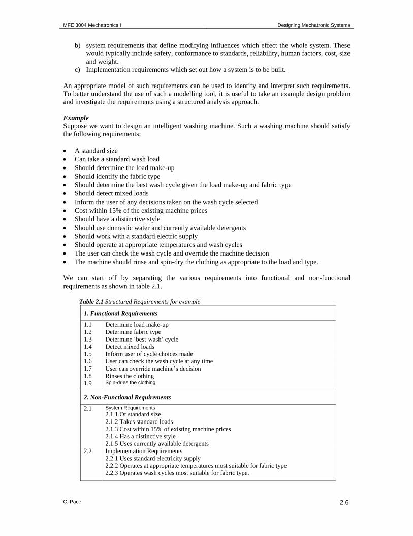
c) Implementation requirements which set out how a system is to be built. An appropriate model of such requirements can be used to identify and interpret such requirements. To better understand the use of such a modelling tool, it is useful to take an example design problem and investigate the requirements using a structured analysis approach. Example Suppose we want to design an intelligent washing machine. Such a washing machine should satisfy the following requirements; • A standard size • Can take a standard wash load • Should determine the load make-up • Should identify the fabric type • Should determine the best wash cycle given the load make-up and fabric type • Should detect mixed loads • Inform the user of any decisions taken on the wash cycle selected • Cost within 15% of the existing machine prices • Should have a distinctive style • Should use domestic water and currently available detergents • Should work with a standard electric supply • Should operate at appropriate temperatures and wash cycles • The user can check the wash cycle and override the machine decision • The machine should rinse and spin-dry the clothing as appropriate to the load and type. We can start off by separating the various requirements into functional and non-functional requirements as shown in table 2.1.
Table 2.1 Structured Requirements for example
1. Functional Requirements
1.1 Determine load make-up 1.2 Determine fabric type 1.3 Determine ‘best-wash’ cycle 1.4 Detect mixed loads 1.5 Inform user of cycle choices made 1.6 User can check the wash cycle at any time 1.7 User can override machine’s decision 1.8 Rinses the clothing 1.9 Spin-dries the clothing
2. Non-Functional Requirements
2.1 System Requirements 2.1.1 Of standard size 2.1.2 Takes standard loads 2.1.3 Cost within 15% of existing machine prices 2.1.4 Has a distinctive style 2.1.5 Uses currently available detergents
2.2 Implementation Requirements 2.2.1 Uses standard electricity supply 2.2.2 Operates at appropriate temperatures most suitable for fabric type 2.2.3 Operates wash cycles most suitable for fabric type.
MFE 3004 Mechatronics I Designing Mechatronic Systems
C. Pace 2.7
The above list of requirements is far from complete. For example certain functional requirements can immediately be noted as missing, such as loading method or detergent determination and loading. Furthermore, there are various constraints, such as system safety and reliability as well as various performance characteristics, which have not been stipulated. These and other requirements can be more easily identified as the requirements are appropriately represented and structured in a requirements analytical model. 2.4.2 Functional Analysis and Modelling Developing a functional model of system requirements is a very powerful method for understanding and clarifying those requirements and the interrelations between them. Moreover, a good functional model of the ‘problem’ can also form a basis for conceptual design since as design decisions are made the model can evolve to reflect them. Since we are using such a technique for modelling mechatronic systems, it is necessary that the functional analysis approach be; • sufficiently abstract to capture both physical and information characteristics • able to include human and other non-technical forms of interaction • able to present the information in a clear and simple fashion.
There are various functional modelling techniques, mostly originating from the software-engineering field that are applicable in this case. The scope of any modelling technique used is that of being able to represent the necessary knowledge in a structured form, which can then make the problem solution more manageable. Here we will consider one such technique that allows us to clearly depict the functionality of the system through the information/energy transfer pattern that would be required. The technique, namely, ‘Yourdon’ or ‘DeMarco’ Analysis, also referred to as ‘Structured Analysis’, is once more a technique developed for software systems and was originally targeted to modelling functionality through the information transfer requirements. This model can, however, be very easily adapted to depicting not only information flow but also the energy transfer. It should be remembered that this technique is useful for analysing the whole system functionality, and that is why it can be so useful from a Mechatronics system perspective. Other design tools should be applied in conjunction to this technique in order to analyse individual design problems, such as problems involving mechanical elements design, electronics design or software design. 2.4.3 Structured Analysis This functional analysis technique offers a number of advantageous characteristics that help structure the system requirements without having to divide the design problem into the individual technologies. In addition the technique provides a mode in which the system problem can be divided into sub-system functionality problems. This technique is based on a diagrammatic representation of the functional requirements and the mode in which such requirements may interact. The basic concepts which form the core of the structured analysis technique, and which make it so suitable for analysing mechatronic system requirements are the following; a. Use of representational diagrams – diagrams are far less ambiguous than natural language for
defining and structuring requirements. In addition, we can present a lot of information in a comparatively simple diagram, contrary to a textual definition. This is very significant when we want to convey the structure and interrelations of requirements.
b. Information Hiding – Information hiding has already been mentioned earlier on. Structured analysis provides us with the ability to only handle the information of relevance when investigating a sub-problem of the system. This is done through a logical hierarchical set of diagrams, where the further we go down the hierarchy, the more the system functional requirements are divided into function sub-problems, and depicted in further detail. On the other hand, the further one goes up the representation hierarchy, the less detailed and more abstract the representation becomes, depicting a level of information that can be easily handled.
c. Abstraction – Abstraction here refers to the ability to represent different technological and physical domains with relative ease. The structured analysis provides a representation that is not
MFE 3004 Mechatronics I Designing Mechatronic Systems
C. Pace 2.8
directly linked to any physical domain, but simply handles the mode in which functional requirements share and convey information and provide for the necessary energy transfer.
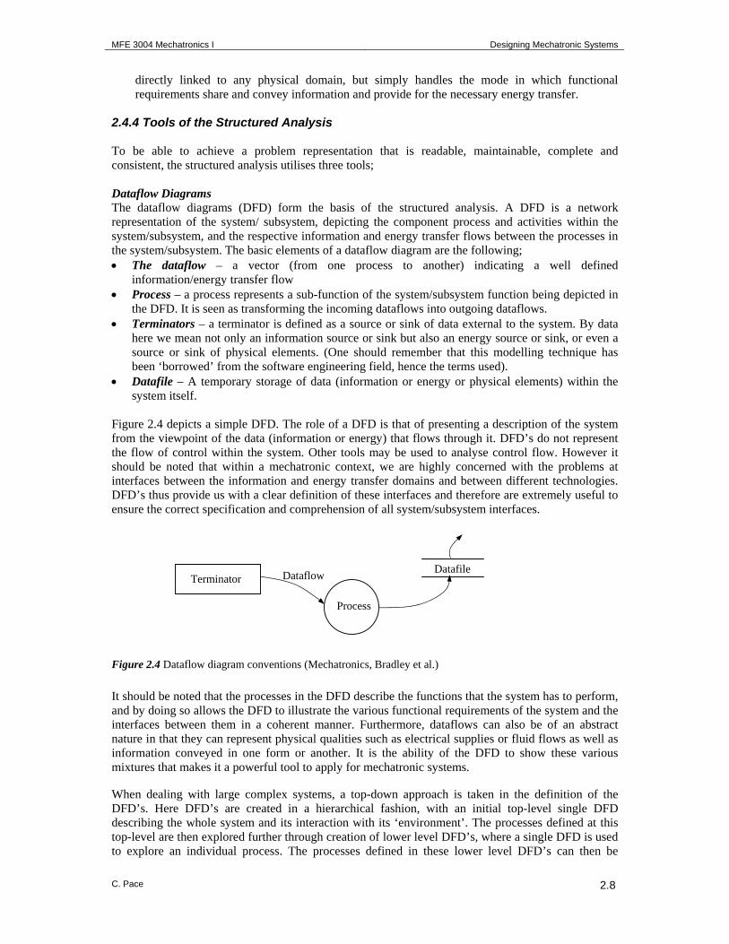
2.4.4 Tools of the Structured Analysis To be able to achieve a problem representation that is readable, maintainable, complete and consistent, the structured analysis utilises three tools; Dataflow Diagrams The dataflow diagrams (DFD) form the basis of the structured analysis. A DFD is a network representation of the system/ subsystem, depicting the component process and activities within the system/subsystem, and the respective information and energy transfer flows between the processes in the system/subsystem. The basic elements of a dataflow diagram are the following; • The dataflow – a vector (from one process to another) indicating a well defined
information/energy transfer flow • Process – a process represents a sub-function of the system/subsystem function being depicted in
the DFD. It is seen as transforming the incoming dataflows into outgoing dataflows. • Terminators – a terminator is defined as a source or sink of data external to the system. By data
here we mean not only an information source or sink but also an energy source or sink, or even a source or sink of physical elements. (One should remember that this modelling technique has been ‘borrowed’ from the software engineering field, hence the terms used).
• Datafile – A temporary storage of data (information or energy or physical elements) within the system itself.
Figure 2.4 depicts a simple DFD. The role of a DFD is that of presenting a description of the system from the viewpoint of the data (information or energy) that flows through it. DFD’s do not represent the flow of control within the system. Other tools may be used to analyse control flow. However it should be noted that within a mechatronic context, we are highly concerned with the problems at interfaces between the information and energy transfer domains and between different technologies. DFD’s thus provide us with a clear definition of these interfaces and therefore are extremely useful to ensure the correct specification and comprehension of all system/subsystem interfaces. Figure 2.4 Dataflow diagram conventions (Mechatronics, Bradley et al.) It should be noted that the processes in the DFD describe the functions that the system has to perform, and by doing so allows the DFD to illustrate the various functional requirements of the system and the interfaces between them in a coherent manner. Furthermore, dataflows can also be of an abstract nature in that they can represent physical qualities such as electrical supplies or fluid flows as well as information conveyed in one form or another. It is the ability of the DFD to show these various mixtures that makes it a powerful tool to apply for mechatronic systems. When dealing with large complex systems, a top-down approach is taken in the definition of the DFD’s. Here DFD’s are created in a hierarchical fashion, with an initial top-level single DFD describing the whole system and its interaction with its ‘environment’. The processes defined at this top-level are then explored further through creation of lower level DFD’s, where a single DFD is used to explore an individual process. The processes defined in these lower level DFD’s can then be
Terminator
Process
Dataflow Datafile
MFE 3004 Mechatronics I Designing Mechatronic Systems
C. Pace 2.9
analysed in turn, in greater detail by depicting their functionality through further lower level DFD’s. The definition of processes and sub-processes through successive DFD’s levels is continued until it is not justifiable to break down a process into its sub-processes via a lower level DFD. These lowest level primitive processes can then be described rigorously enough by a process specification (defined later on as another building block of structured analysis). The mode of labelling and naming DFD’s is handled by a set of structured analysis rules. The labelling rules will be viewed when we consider a specific example of how such an approach is used. Data Dictionary The data dictionary (DD) is used as a way of specifying precisely what is meant by the terms used in the dataflow diagrams. In particular it is concerned with giving exact definitions to dataflows and datafiles, i.e. describing what the dataflow or datafile physically represents. Just as the DFD effects a top-down decomposition of the processes within the system, the data dictionary effects a decomposition of the data. For example, the dataflows and datafiles described at the top level DFD’s would be defined as being groups of subordinate items, where such items may be one or more data items in their own right. As stated earlier, the dataflows and datafiles used in the DFD’s can be abstract in nature and should be clearly defined in the DD. For example there is no reason why a piece of steel bar entering a machine tool cannot be considered as a dataflow and the machine tool as a process. Similarly, the machined part coming off the machine tool constitutes an outgoing dataflow. The data dictionary uses a set of simple relations to define any possible dictionary entry. This set comprises of the following operators; IS EQUIVALENT TO AND EITHER-OR ITERATIONS OF OPTIONAL An example of a DD definition would be: Telephone_directory IS EQUIVALENT TO ITERATIONS OF EITHER : Business_Name OR : Personal_Surname AND : OPTIONAL Initials AND : Address AND : Telephone_number Which can be simplified by using the abbreviated notation which follows; Telephone_Directory = {[Business_Name/Personal_Surname + (Initials)] + Address +
Telephone_Number} Note that this definition uses what is known structured English to ensure that there is no ambiguity in the definition of a dataflow. Process Specification The Process specification (PS) specifies the component processes, in particular the primitive processes which are not broken down further through lower level DFD’s. The PS defines the required function governing the transformation from the input dataflows to the output dataflows but does not represent the method of implementation. It is merely a definition of the required functionality of the process. Furthermore, it is also possible to represent the effect of the non-functional requirements, such as constraints within process specifications. This ensures that the constraints on the system functional requirements are represented in a structured manner.
MFE 3004 Mechatronics I Designing Mechatronic Systems
C. Pace 2.10
Once more, the PS is documented using Structure English to ensure that no ambiguity likely to occur in normal English will appear. Structured English basically consists of the terms described for the data dictionary together with imperative verbs and logic formulations such as IF-THEN, or WHILE. The DFD, DD, and PS (figure 2.5) together allow the construction of the system requirements model that is consistent, complete, and unambiguous. Furthermore, the model also serves as a descriptive document for the system. It also provides a structured problem breakdown that is of particular benefit when coming to the concept selection, design embodiment and detailed design phases. Figure 2.5 A Structured Analysis Model One of the major advantages of such a requirements description model is that it is not technology specific and therefore can be used relatively easily by all members of a design team to represent the system requirements without the need of investigating the individual technological requirements at this early design stage. In addition, this representation ensures that all design members now share a common view of the system requirements. However, it should be noted, that this model on its own does not provide all the requirements analysis necessary, as the model only provides a means of visualising information flow and energy transfer. As mentioned earlier, timing and control aspects are not specifically depicted in this model, and additional tools may be required. 2.4.5 Developing a structured analysis for the washing machine example The following dataflow diagrams and data dictionary and process specification demonstrate typical diagrams and entries that have been applied for the washing machine example described earlier on.
P
Dataflow Datafile
DATA DICTIONARY Datafile ……………. ……………………
PROCESS SPECIFICATION P …………….…………………………
DATAFLOW
MFE 3004 Mechatronics I Designing Mechatronic Systems
C. Pace 2.11
Dataflow Diagrams Figure 2.6 (Top level) Context diagram for washing machine example (Mechatronics, Bradley et al.), outlining operational requirement of system and its interaction with the world. Figure 2.7 Level 0 dataflow diagram - Wash Clothes intelligently, for washing machine example (Mechatronics, Bradley et al.), outlining the main functional subdivisions of the operational requirement outlined in the context diagram. Note that the dataflows flowing in and out of the diagram correspond to the same dataflows flowing between the single process and the terminators in the context diagram.
Wash Clothes
Intelligently
Installers Domestic Services
User Service Providers
INSTALLATION_SERVICE
SERVICES
WASTE
MAINTENANCE_SERVICE
FAULT_CODES
MACHINE_OUTPUTS
USER_INPUTS
SERVICE_REQUEST
Install Washing Machine
1
SERVICES
Maintain Washing Machine
3
Use Washing Machine
2
FAULT_CODES
MAINTENANCE_SERVICE
WASTE MACHINE_OUTPUTS
USER_INPUTS
INSTALLATION_SERVICE
MFE 3004 Mechatronics I Designing Mechatronic Systems
C. Pace 2.12
Figure 2.8. Level 1 dataflow diagram – USE WASHING MACHINE, for washing machine example (Mechatronics, Bradley et al.), outlining the functional subdivisions of the Use Washing Machine process in the level 0 diagram. Note that the dataflows flowing in and out of the diagram correspond to the same dataflows flowing in and out of the ‘Use Washing Machine’ process in the level 0 diagram. This ensures consistency between two levels of diagrams. Note that the above level 1 diagram can be broken down further (by developing dataflow diagrams for the identified processes) to explore further the functional requirements of the processes. Alternatively the processes can be considered as primitive processes and can be defined in a process specification. The same procedure applies for the principle processes identified in the level 0 diagram. Data Dictionary Here are some entries of the data dictionary Level 0 Diagram SERVICES = MAINS_POWER + (WATER_SUPPLIES) MACHINE_OUTPUTS = CLEAN_CLOTHES + USER_INFORMATION USER_INPUTS = USER_COMMANDS + DIRTY_CLOTHES + DETERGENT + (CONDITIONER) FAULT_CODES = D_B_W_C_FAULT + D_L_FAULT + W_C_FAULT WASTE = WASTE_WATER Level 1 Diagram – 2. Use Washing Machine DIRTY_CLOTHES = Up to X kg of clothes to be washed of various types of fabric and colour LOADED_CLOTHES = DIRTY_CLOTHES in Washing Machine MAINS_POWER = 240V A.C. electrical supply DETERGENT_CONDITIONER = loaded Standard Detergent + loaded Standard Conditioner WATER_SUPPLIES = standard flow of Hot water + standard flow of Cold water WASTE_WATER = water flow to be drained in standard drain system LOAD_MAKE_UP = Weight of Load + Fabric Types + Colours BEST_WASH_CYCLE = Automatically Selected Temperature + Automatically Selected Wash cycle steps + Automatically Selected Detergent/ Conditioner amount + Automatically Selected Wash cycle time + Automatically Selected spin speed
Load Dirty Clothes
2.1
LOADED_CLOTHES
Determine Load 2.2 Wash
Clothes 2.4
FAULT_CODES
DETERGENT_CONDITIONER
D_B_W_C_FAULT
MAINS_POWER
WASHED_CLOTHES
DIRTY_CLOTHES
WATER_SUPPLIES
WASTE_WATER
Determine Best Wash
Cycle 2.3
MAINS_POWER
LOAD_MAKE_UP
Communicate
with User 2.5
BEST_WASH_CYCLE
D_L_FAULT
W_C_FAULT
SELECTED_WASH_CYCLE
Unload Clean
Clothes 2.6
CLEAN_CLOTHES MAINS_POWER
USER_COMMANDS
USER_INFORMATION
MFE 3004 Mechatronics I Designing Mechatronic Systems
C. Pace 2.13
SELECTED_WASH_CYCLE = User chosen Temperature + User chosen Wash cycle steps + User chosen detergent/conditioner amount + user chosen wash cycle time + user chosen spin speed The following describes the process specification for process 2.1, COMMUNICATE WITH USER, in the level 2 dataflow diagram; PROCESS SPECIFICATION PROCESS 2.1 COMMUNICATE WITH USER WHILE MAINS_POWER ON DO THE FOLLOWING Generate USER_MESSAGE appropriate to BEST_WASH_CYCLE Display USER_MESSAGE Await USER_COMMAND Determine appropriate action CASE 1 USER_COMMAND = GO Start wash cycle using BEST_WASH_CYCLE CASE 2 USER_COMMAND = MANUAL_OVERRIDE Start wash cycle using MANUAL_OVERRIDE 2.5 Mechatronic Hardware and Software
Design 2.5.1 Designing Mechatronic Hardware The mechatronics environment is substantially concerned with the sensing and actuation requirements of a system. Indeed, these have been indicated as the interfaces between the two principle domains of a mechatronic system – information processing and energy transfer. Through adequate design and development procedures, a design team should achieve a hardware and software set-up that satisfies the required functionality and moreover, that reserve little surprises on first start-up, because the system has been analysed and predicted during the process of design. Even experienced designers, when viewing the design task at an early conceptual stage, will find the choice of mode of operation and implementation to be quite daunting, because of the numerous options that can potentially satisfy such requirements. In addition this is one of the most crucial stages in design, since the major design decisions that will influence the whole design, development process are taken at this stage. What the engineering designer needs is to arrive as quickly as possible to a scheme which will satisfy the functional requirements of the project and which also meets the non-functional requirements such as cost targets. The functional requirements will include basic parameters which can be set in terms of static or steady state conditions such as force, torque, rotational speed, linear velocity, peak acceleration and also requirements which are most appropriately evaluated by simulation, such as frequency response and stability. The non-functional requirements may include commercial constraints together with the manufacturing profile of the organisation. Appropriate modelling of the electro-mechanical system will allow such evaluation of both steady-state and dynamic operational characteristics of the hardware. The design process implies a number of feedback loops with continuous re-evaluation taking place. Here, the emerging partial solutions to the problem can be tested against the partitioned design specification requirements.
MFE 3004 Mechatronics I Designing Mechatronic Systems
C. Pace 2.14
2.5.2 Software Design Figure 2.9 illustrates what is known as the software lifecycle. The software lifecycle emphasises the fact that software when in use, is subject to a process of continuous upgrading to take account of changes in the available processors or to correct errors found in earlier versions.
Figure 2.9 The software lifecycle The phases of development of the software lifecycle can be seen as consisting of four major stages; Requirements Analysis At this stage the performance requirements of the software are established together with the system on which the software is to run. The emphasis here is on the necessity for the software engineer to work with the users of the software, in order to investigate and evaluate the context in which the software is to operate. The focus at this stage is on ‘what’ should be done rather than ‘how’ it should be done.
MFE 3004 Mechatronics I Designing Mechatronic Systems
C. Pace 2.15
Design Here, the software is broken down into modules and sub-modules and the links between the modules are defined. Designing software in a modular form allows the independent development and testing of individual modules prior to assembling the modules together. Implementation At this stage, the code of the individual modules is implemented. A modular design allows different programmers to be involved in the development and implementation of the different modules. Testing The goal of testing is to try and identify and correct as much software errors as possible. Testing of software is a complex process and usually involves a number of stages. The testing needs to be done to verify whether the code does what it is supposed to do and to validate the software against the original requirements. The modular design aids testing by being able to break down tests for the individual modules. Simpler tests can then be performed on the linking up of the individual modules. 2.5.3 Top-Down versus Bottom-Up Design Approaching the design of both system hardware and software can be done in both a top-down or bottom-up fashion. In a top-down approach to design the designer starts at the highest level of the system problem definition and gradually decomposes the problem down into its realisable elements, each of which can then be dealt with individually. This type of approach is most commonly used in software design where the software functionality problem is decomposed into modules each with specific interface requirements. Each of these modules can then be developed individually and ultimately assembled to form the complete system. In a bottom-up approach, a low-level element of the system would initially be identified and defined and the remainder of the system constructed from this basis. Bottom-up design strategies are more typical of electronics design, where there is a need to establish the operation and performance of an element before the rest of the design can proceed. In practice, most design follows a mixture of top-down and bottom-up approaches, with the designer alternating between the two as the design progresses. This need to switch strategies may result from the need to evaluate a particular concept or approach before the design can proceed any further. 2.5.4 Design Support Tools Various design support tools have been developed reflecting the nature and development approaches of the different technologies found in mechatronic systems. Yet, relatively little has been done to integrate these individual tools. Methodologies developed for software engineering, seem to best reflect the systems approach philosophy, with software support tools designed to help modularise the software development. Such tools are generally implemented in the form of Computer Aided Software Engineering (CASE). Electronics has seen the use of computer based design aid tools particularly for VLSI design. Most of these tools include simulation packages. Mechanical engineering also has a wide variety of design support tools in the form of CAD/CAE systems. Packages for simulation include the capability of modelling systems both physically and mathematically for analytical purposes. Detailed 3D physical representations are also possible with more advanced CAD systems. These tools, however useful in the development of a mechatronic system, do not fully represent the integration aspects of Mechatronic systems. In such cases, general system modelling tools such as those mentioned earlier, which allow a full system representation, provide a means of linking the development of the individual technologies which in turn is aided through the use of the technology-specific design support tools.
MFE 3004 Mechatronics I Designing Mechatronic Systems
C. Pace 2.16
2.5.5 Simulation and Design Simulation can be described as the construction of a model of a system in order to better understand the behaviour of that system under a range of conditions and to evaluate various operational modes for the system. Simulation can be extremely useful particularly in analysing complex systems such as mechatronic products and processes, since it offers the possibility of understanding the system before any major physical development costs are committed. Simulation models may be of different forms such as; • Physical models – can be used to demonstrate specific physical features of a system, such as
would be the case of experimenting with models in wind tunnels. Simulations with physical models are generally expensive and are mostly used where other non-physical modelling techniques would get to complex in order to fully represent the actual system under investigation.
• Mathematical models – such models allow the simulation of the static and dynamic behavioural characteristics of a system. Mathematical models can be used for modelling controlled behaviour of systems. However, even though such models give very accurate results, they can become highly complex and difficult to verify when used to model more complex mechatronic systems. Software packages such as Matlab, Simulink and Labview, provide analytical tools for handling such mathematical models.
• Computer graphics models – these models are mostly used for visualisation purposes and include tools such as virtual reality (VR) techniques.
References David Bradley, Derek Seward, David Dawson, Stuart Burge, “Mechatronics and the design of Intelligent Machines and Systems”, Stanley Thornes Publ., 2000 Rolf Isermann, “Mechatronic Systems Fundamentals”, Springer Verlag, 2005.