24
| Date post: | 13-Dec-2015 |
| Category: |
Documents |
| Upload: | millicent-walton |
| View: | 213 times |
| Download: | 0 times |


2
DGS-SEE SEMINAR ON FIRE PROTECTION FOR PHYSICS RESEARCH FACILITIES 07-08 OCTOBER 2015
CERN
FIRE SIMULATIONS IN THE PS ACCELERATOR TUNNEL TO DEFINE A SMOKE EXTRACTION
STRATEGYTRISTAN HEHNEN

3
Table of contents
• Introduction• Introduction• Aim of the study• Tunnel description
• Proposed model• General information• Model overview
• First results• Smoke propagation• Near field of the fire
• Possible Improvements

4
Introduction

5
• Member of the Doctoral Student Programme at CERN
• Work supported by the Wolfgang-Gentner-Programme of the German Federal Ministry of Education and Research (BMBF)
• Doctoral student at the Bergische Universität Wuppertal
• Department: Computer Simulation for Fire Safety and Pedestrian Traffic
Duration of the doctoral programm: from Nov. 2014 to Nov. 2017
Supervisor: Saverio La Mendola
Supervisor: Armin SeyfriedLukas Arnold
Introduction

6
Aim of the study
• Aim: Estimate the amount of radioactive material within the smoke in case of fire.
• Study devided in two parts:– Part I: Fire simulation (by Tristan)
– Part II: Estimate amount of radioactive material in the smoke and possible environmental impact (by Joachim)
• This presentation is on Part I– Aim: Create an envelope case of the fire scenario to further
explore the conditions
– Provide mass release over time, based on heat of combustion, as input for Part II

7
TR 4
TR 3
TR 2
Tunnel description
• Simulation of cable fire in trench• Simplified part of the tunnel,
represented as straight section
• Roughly a quarter of the ring (TR 2 to TR 4)
• No fire propagation over combustible items simulated
• Burnable gas injected into the domain (gasburner)
• Smoke detection after 9 min – ventilation system stopped

8
• Data on ventilation system taken from EDMS 1296553 and EDMS 1224638 (CFD study of PS ventilation system)
• Injection and extraction air volume fluxes are equal
• Representation of Fresh Air Ventilation System (FAVS) and Recirculation Ventilation System (RVS) by according volume fluxes
• Nozzles of RVS represented by larger surface – similar to previous CFD study
Tunnel description

9
• Volume fluxes:– FAVS 2500 m³/h (1250 m³/h in each direction) in
the middle of tunnel segment (TR 3)
– RVS • Section TR 2 – TR 3: 40000 m³/h
• Section TR 3 –TR 4: 35000 m³/h
• Proposal: Three simulations for exploration of the scenario
– Wooden panals stay in place
– No wooden panels
– Panels will disapear gradually
Tunnel description
10
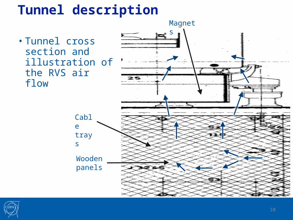
Tunnel description
• Tunnel cross section and illustration of the RVS air flow
Cable trays
Magnets
Wooden panels

11
Proposed model

12
• Simulations conducted with Fire Dynamics Simulator 6.1.2 (FDS)
• Fire simulated with αt²-approach: slow α, progress to 10 MW• Grid resolution changes:
– Two meshes
– Top mesh with 20 cm cubes
– Buttom mesh with 10 cm cubes
• Both tunnel ends opend to account for leakage• Flow through these openings is monitored
General information
13
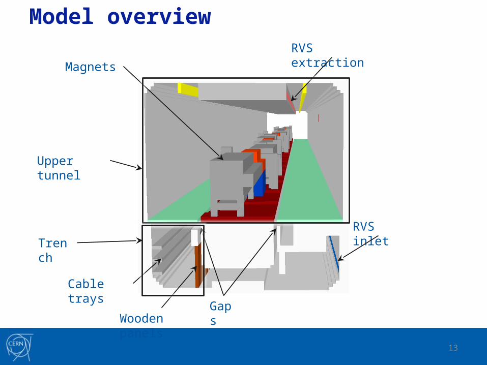
Gaps
RVS inlet
RVS extraction
Magnets
Wooden panels
Cable trays
Model overview
Upper tunnel
Trench

14
Gasburner
RVS inlet
RVS extraction
Magnets
Wooden panels
• Part of the tunnel at the centre
Cable trays
Model overview

15
RVS inlet
RVS extraction
Magnets
Wooden panels
Cable trays
Model overview

16
~ 200 m
FAVS inlet
FAVS extraction
Model overview

17
10 cm cubes
20 cm cubes
• Two Meshes with different cell size to save computational time
Model overview

18
Opend tunnel ends
• Opend tunnel endings (upstream end shown here)
Model overview

19
First results

20
• Smoke distribution ~417 s after ignition– Roughly 100 m propagation in the upper part
– Roughly 60 m propagation in the trench
Smoke propagation

21
Flow through the gap
• Velocity profile, ~417 s after ignition
Near field of the fire

22
• Temperature profile, ~417 s after ignition
Near field of the fire

23
• Possible improvements of the model:– Behaviour of the ventilation system not modelled:
• No duct network, no fans, no dampers ...
• Just fixed volume flux for inflow/outflow
• Turned off after 9 min
– Finer resolution for gap between magnets and trench
– Fire propagation prescribed, no propagation over combustible material
– Leakage of the PS tunnel not known, modelled as openings in the tunnel ends
– No leakage in the ceiling of the trench
– Tunnel modelled as straight section and not in the full extend - change in air volume available
Possible improvements

24
Thank you for your attention!
Do you have any questions?


