2. Flanged gate valves for water 3. Other gate valves for water 4. Combi valves 5. Service connection valves for water 6. Valves and fittings for gas 7. Fire hydrants 8. Check valves 9. Air valves 10. Butterfly valves and other valves 11. Flange adaptors and couplings 12. Tapping saddles and repair clamps 13. Accessories for valves 14. Technical information 15. 1. General company and product information
Transcript
2. Flanged gate valves for water
3. Other gate valves for water
4. Combi valves
5. Service connection valves for water
6. Valves and fittings for gas
7. Fire hydrants
8. Check valves
9. Air valves
10. Butterfly valves and other valves
11. Flange adaptors and couplings
12. Tapping saddles and repair clamps
13. Accessories for valves
14. Technical information
15.
1. General company and product information
22. Flanged gate valves for water
For further specification, see section "Technical information".The designs, materials and specifications shown are subject to change without notice due to our continuing programme of product development.
AVK INTERNATIONAL A/S/99
AVK GATE VALVE PN 10 OR PN 16 02/X0 - 20/30
To DIN 3352 part 4Face to face dimension to DIN 3202 part 1, F5Flanges and drilling to ISO 7005-2 (EN 1092-2: 1997, DIN 2501)
Use:
For water, sewage and neutral liquids tomax. 70°C
Tests:
Hydraulic test to DIN 3230 part 4:Seat: PNBody: 1.5 x PN
Operating torque test
Optional extras:
HandwheelExtension spindleStem capFlange adaptor
Approvals:Series 02/60 and 20/30:DIN-DVGW-Reg.-Nr. 1161
Series 02/50:KIWA - NL
Materials:
Body and bonnet Series 02/60 and 20/30:Ductile iron, GGG-50, to DIN 1693(BS 2789 grade 500 - 7)Series 02/50:Grey cast iron, GG-25, to DIN 1691(BS 1452 grade 220/250)
Coating Series 02/50 and 02/60:Electrostatically applied epoxy resin
to DIN 30677 - Internally and externally
Series 20/30:Electrostatically applied epoxy resin
to DIN 30677 - externally. Enamelled internally.
Stem Stainless steel, DIN X 20 Cr 13Stem sealing NBR wiper ring, 2 NBR O-rings inside
and 2 outside a plastic bearing, EPDM rubber manchette
Wedge Ductile iron, GGG-50, core fullyvulcanised with EPDM rubber,with integral wedge nut ofdezincification resistant brass,CZ 132 to BS 2874
Thrust collar Dezincification resistant brass, CZ 132 to BS 2872
Bonnet bolts Stainless steel A2, sealed with hot melt
Bonnet gasket EPDM rubber
AVK GATE VALVE PN 10 OR PN 16 02/X0 - 20/30
To DIN 3352 part 4Face to face dimension to DIN 3202 part 1, F5Flanges and drilling to ISO 7005-2 (EN 1092-2: 1997, DIN 2501)
1
2
3
4
5
6
7
9
10
11
12
8
L
H
F
ds
Ref. nos. Dh dsGG-25 GGG-50 GGG-50 L H Dt D mm mm Holes F Weight
Internal epoxy Internal epoxy Internal enamel DN mm mm mm mm PN 10 PN 16 PN 10 PN 16 PN 10 PN 16 mm kilos
* Flanges drilled to DIN 2501 350 mm, having an increased (400 mm) bore.** Flanges drilled to DIN 2501 450 mm, having a reduced (400 mm) bore.*** Flanges drilled to DIN 2501 500 mm, having a reduced (400 mm) bore.
For further specification, see section "Technical information".The designs, materials and specifications shown are subject to change without notice due to our continuing programme of product development.
AVK INTERNATIONAL A/S/99
AVK GATE VALVE PN 10 OR PN 16 06/X0 - 26/00
To DIN 3352 part 4 / NF E 29-324Face to face dimension to DIN 3202 Part 1, F4Flanges and drilling to ISO 7005-2 (EN 1092-2: 1997, DIN 2501)
Use:
For water, sewage and neutral liquids tomax. 70°C
Tests:
Hydraulic test to DIN 3230 part 4:Seat: PNBody: 1.5 x PN
Operating torque test
Optional extras:
HandwheelExtension spindleStem capFlange adaptor
Approvals:
Series 06/30:ÖVGW - Reg. Nr.: W1.121Series 26/00:DVGW - Reg. Nr.: 81.03 e 397
Materials:
Body and bonnet Series 06/30 and 26/00:Ductile iron, GGG-50, to DIN 1693(BS 2789 grade 500 - 7)Series 06/40:Grey cast iron, GG-25, to DIN 1691(BS 1452 grade 220/250)
Coating Series 06/30 and 06/40:Electrostatically applied epoxy resinto DIN 30677 - Internally and externallySeries 26/00:Electrostatically applied epoxy resinto DIN 30677 - externally. Enamelled internally.
Stem Stainless steel, DIN X 20 Cr 13Stem sealing NBR wiper ring, 2 NBR O-rings
inside and 2 outside a plastic bearing, EPDM rubber manchette
Wedge Ductile iron, GGG-50, core fullyvulcanised with EPDM rubber,with integral wedge nut ofdezincification resistant brass,CZ 132 to BS 2874
Thrust collar Dezincification resistant brass, CZ 132 to BS 2872
Bonnet bolts Stainless steel A2, sealed with hot melt
X: 0= PN 10 1 = PN 16In the sizes DN 250 and DN 300 the upper bolt holes in the flanges are metric threaded (M20 for PN 10 and M24 for PN 16).
AVK GATE VALVE PN 10 OR PN 16 06/X0 - 26/00
To DIN 3352 part 4 / NF E 29-324Face to face dimension to DIN 3202 Part 1, F4Flanges and drilling to ISO 7005-2 (EN 1092-2: 1997, DIN 2501)
1
2
3
4
5
6
7
9
10
11
12
8
L
H
F
ds
DDhDt
For further specification, see section "Technical information".The designs, materials and specifications shown are subject to change without notice due to our continuing programme of product development.
AVK INTERNATIONAL A/S/99
AVK GATE VALVE PN 25 02/67
To DIN 3352 part 4Face to face dimension to DIN 3202 part 1, F5Flanges and drilling to ISO 7005-2 (EN 1092-2: 1997, DIN 2501)
Use:
For water and neutral liquids to max.70°C
Tests:
Hydraulic test to DIN 3230 part 4:Seat: PNBody: 1.5 x PN
Operating torque test
Optional extras:
HandwheelExtension spindleStem cap
Materials:
Body and bonnet Ductile iron, GGG-50, to DIN 1693(BS 2789 grade 500 - 7)
Coating Electrostatically applied epoxy resinto DIN 30677 - Internally and externally
Stem Stainless steel, DIN X 20 Cr 13Stem sealing *) NBR wiper ring, 2 NBR O-rings inside
and 2 outside a plastic bearing, EPDM rubber manchette
Wedge Ductile iron, GGG-50, core fullyencapsulated with EPDM rubberwith integral wedge nut ofgunmetal RG5 to DIN 1705
Thrust collar Dezincification resistant brass, CZ 132 to BS 2872
Bonnet bolts Stainless steel A2, sealed with hot melt
Bonnet gasket EPDM rubber
*) Optionally:Series 02/68 With exhangeable stem sealing:
NBR wiper ring, 4 NBR O-ringsand a EPDM rubber manchette.Stem seal nut of dezincification resistant brass, CZ 132 to BS 2874
AVK GATE VALVE PN 25 02/67
To DIN 3352 part 4Face to face dimension to DIN 3202 part 1, F5Flanges and drilling to ISO 7005-2 (EN 1092-2: 1997, DIN 2501)
L H Dt D Dh ds Holes F WeightRef. nos. DN mm mm mm mm mm mm mm kilos
For further specification, see section "Technical information".The designs, materials and specifications shown are subject to change without notice due to our continuing programme of product development.
AVK INTERNATIONAL A/S/99
AVK GATE VALVE PN 10 OR PN 16 02/75
To DIN 3352 part 4 / NFE 29-324. Stem sealing exchangeable under pressureFace to face dimension to DIN 3202 part 1, F5Flanges and drilling to ISO 7005-2 (EN 1092-2: 1997, DIN 2501)
Use:
For water, sewage and neutral liquidsto max. 70°C
Tests:
Hydraulic test to DIN 3230 part 4:Seat: PNBody: 1.5 x PN
Operating torque test
Optional extras:
HandwheelExtension spindleStem capFlange adaptor
Materials:
Body and bonnet Ductile iron, GGG-50, to DIN 1693(BS 2789 grade 500 - 7)
Coating Electrostatically applied epoxy resinto DIN 30677 - Internally and externally
Stem Stainless steel, DIN X 20 Cr 13Stem sealing NBR wiper ring, 4 NBR O-rings and
a EPDM rubber manchetteStem seal nut Dezincification resistant brass,
CZ 132 to BS 2874Wedge Ductile iron, GGG-50, core fully
vulcanised with EPDM rubber,with integral wedge nut ofdezincification resistant brass,CZ 132 to BS 2874
Thrust collar Dezincification resistant brass, CZ 132 to BS 2872
Bonnet bolts Stainless steel A2, sealed with hot melt
Bonnet gasket EPDM rubber
Approvals:
DIN-DVGW NW-6202AU2049
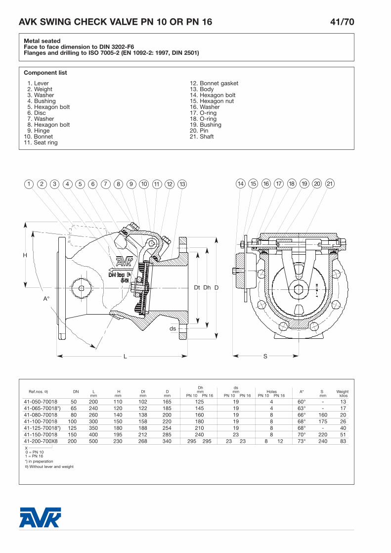
Component list
AVK GATE VALVE PN 10 OR PN 16 02/75
To DIN 3352 part 4 / NFE 29-324. Stem sealing exchangeable under pressureFace to face dimension to DIN 3202 part 1, F5Flanges and drilling to ISO 7005-2 (EN 1092-2: 1997, DIN 2501)
1
2
3
4
5
6
7
9
10
11
12
8
L
H
F
Dt
ds
Dh
Dh dsL H D Dt mm mm Holes F Weight
Ref. nos. DN mm mm mm mm PN 10 PN 16 PN 10 PN 16 PN 10 PN 16 mm kilos
* Flanges drilled to DIN 2501 350 mm, having an increased (400 mm) bore.** Flanges drilled to DIN 2501 450 mm, having a reduced (400 mm) bore.*** Flanges drilled to DIN 2501 500 mm, having a reduced (400 mm) bore.
For further specification, see section "Technical information".The designs, materials and specifications shown are subject to change without notice due to our continuing programme of product development.
AVK INTERNATIONAL A/S/99
AVK GATE VALVE PN 10 OR PN 16 02/40
To BS 5150 / BS 5163 type A / DIN 3230 part 4Face to face dimension to BS 5163Flanges and drilling to ISO 7005-2 (EN 1092-2: 1997, DIN 2501)
Use:
For water, sewage and neutral liquids tomax. 70°C
Tests:
Hydraulic test to DIN 3230 part 4:Seat: PNBody: 1.5 x PN
Operating torque test
Optional extras:
HandwheelExtension spindleStem cap Flange adaptor
Materials:
Body and bonnet Grey cast iron, GG-25, to DIN 1691(BS 1452 grade 220/250)
Coating Electrostatically applied epoxy resinto DIN 30677 - Internally and externally
Stem Stainless steel, DIN X 20 Cr 13Stem sealing NBR wiper ring, 2 NBR O-rings
inside and 2 outside a plastic bearing, EPDM rubber manchette
Wedge Ductile iron, GGG-50, core fullyencapsulated with EPDM rubberwith integral wedge nut ofdezincification resistant brass,CZ 132 to BS 2874
Thrust collar Dezincification resistant brass, CZ 132 to BS 2872
Bonnet bolts Stainless steel A2, sealed with hot melt
To BS 5150 / BS 5163 type A / DIN 3230 part 4Face to face dimension to BS 5163Flanges and drilling to ISO 7005-2 (EN 1092-2: 1997, DIN 2501)
1
2
3
4
5
6
7
9
10
11
12
8
L
H
F
DhDt
ds
D
For further specification, see section "Technical information".The designs, materials and specifications shown are subject to change without notice due to our continuing programme of product development.
AVK INTERNATIONAL A/S/99
AVK GATE VALVE PN 10 OR PN 16 23/30
To BS 5163: 1986 type A. Stem sealing exchangeable under pressureFace to face dimension to BS 5163: 1986Flanges and drilling to ISO 7005-2 (EN 1092-2: 1997, DIN 2501)
Use:
For water, sewage and neutral liquidsto max. 70°C
Tests:
Hydraulic test to BS 5163:Seat: 1.1 x PNBody: 1.5 x PN
Operating torque test
Optional extras:
HandwheelExtension spindleStem capFlange adaptor
Materials:
Body and bonnet Ductile iron, GGG-50, to DIN 1693(BS 2789 grade 500 - 7)
Coating Electrostatically applied epoxy resin- Internally and externally
Stem Stainless steel, DIN X 20 Cr 13Stem sealing NBR wiper ring, 4 NBR O-rings
To BS 5163: 1986 type A. Stem sealing exchangeable under pressureFace to face dimension to BS 5163: 1986Flanges and drilling to ISO 7005-2 (EN 1092-2: 1997, DIN 2501)
1
2
3
4
5
6
7
9
10
11
12
8
L
H
F
ds
DDhDt
For further specification, see section "Technical information".The designs, materials and specifications shown are subject to change without notice due to our continuing programme of product development.
AVK INTERNATIONAL A/S/99
AVK GATE VALVE PN 10 OR PN 16 23/40
To BS 5163: 1986 type A. Stem sealing exchangeable under pressureFace to face dimension to BS 5163: 1986Flanges and drilling to ISO 7005-2 (EN 1092-2: 1997, DIN 2501)
Use:
For water, sewage and neutral liquidsto max. 70°C
Tests:
Hydraulic test to BS 5163:Seat: 1.1 x PNBody: 1.5 x PN
Operating torque test
Optional extras:
HandwheelExtension spindleStem capFlange adaptor
Materials:
Body and bonnet Grey cast iron, GG-25, to DIN 1691(BS 1452 grade 220/250)
Coating Electrostatically applied epoxy resin- Internally and externally
Stem Stainless steel, DIN X 20 Cr 13Stem sealing NBR wiper ring, 4 NBR O-rings
EPDM rubber manchetteStem seal nut Dezincification resistant brass,
CZ 132 to BS 2874Wedge Ductile iron, GGG-50, core fully
vulcanised with EPDM rubber,with integral wedge nut ofdezincification resistant brass,CZ 132 to BS 2874
Thrust collar Dezincification resistant brass, CZ 132 to BS 2872
Bonnet bolts Stainless steel A2, sealed with hot melt
To BS 5163: 1986 type A. Stem sealing exchangeable under pressureFace to face dimension to BS 5163: 1986Flanges and drilling to ISO 7005-2 (EN 1092-2: 1997, DIN 2501)
1
2
3
4
5
6
7
9
10
11
12
8
L
H
F
ds
DDhDt
For further specification, see section "Technical information".The designs, materials and specifications shown are subject to change without notice due to our continuing programme of product development.
AVK INTERNATIONAL A/S/99
AVK GATE VALVE PN 10 OR PN 16 21/00
To BS 5163: 1986 type B. Stem sealing exchangeable under pressureFace to face dimension to BS 5163: 1986Flanges and drilling to ISO 7005-2 (EN 1092-2: 1997, DIN 2501)
Use:
For water, sewage and neutral liquids tomax. 70°C
Tests:
Hydraulic test to BS 5163:Seat: 1.1 x PNBody: 1.5 x PN
Operating torque test
Optional extras:
HandwheelExtension spindleFlange adaptorStem cap
Approvals:
WBS-approved
Materials:
Body and bonnet Grey cast iron, GG-25, to DIN 1691(BS 1452 grade 220/250)
Gland flange Ductile iron, GGG-50, to DIN 1693(BS 2789 grade 500 - 7)
To BS 5163: 1986 type B. Stem sealing exchangeable under pressureFace to face dimension to BS 5163: 1986Flanges and drilling to ISO 7005-2 (EN 1092-2: 1997, DIN 2501)
1
2
3
4
5
6
7
9
10
11
12
13
8
L
H
F
ds
Dt Dh D
For further specification, see section "Technical information".The designs, materials and specifications shown are subject to change without notice due to our continuing programme of product development.
AVK INTERNATIONAL A/S/99
AVK GATE VALVE PN 25 21/60
To BS 5163:1986 type B. Stem sealing exchangeable under pressureFace to face dimension to BS 5163: 1986 Flanges and drilling to ISO 7005-2 (EN 1092-2: 1997, DIN 2501) PN 25
Use:
For water, sewage and neutral liquids tomax. 70°C
Tests:
Hydraulic test to BS 5163:Seat: 1.1 x PNBody: 1.5 x PN
Operating torque test
Optional extras:
HandwheelExtension spindleFlange adaptorStem cap
Approvals:
WBS-approved
Materials:
Gland flange, Ductile iron, GGG-50, to DIN 1693body and bonnet (BS 2789 grade 500 - 7)Gland flange Zinc coated steel 8.8boltsCoating Electrostatically applied epoxy resin
- Internally and externallyStem Stainless steel, DIN X 20 Cr 13Stem sealing NBR wiper ring, 2 NBR O-rings Wedge Ductile iron, GGG-50, core fully
vulcanised with EPDM rubber,with integral wedge nut ofdezincification resistant brass,CZ 132 to BS 2874
Thrust collar and Dezincification resistant brass, stem seal box CZ 132 to BS 2874Bonnet bolts Stainless steel A2, sealed with
To BS 5163:1986 type B. Stem sealing exchangeable under pressureFace to face dimension to BS 5163: 1986 Flanges and drilling to ISO 7005-2 (EN 1092-2: 1997, DIN 2501) PN 25
1
2
3
4
5
6
7
9
10
11
12
13
8
L
H
F
ds
Dt Dh D
For further specification, see section "Technical information".The designs, materials and specifications shown are subject to change without notice due to our continuing programme of product development.
AVK INTERNATIONAL A/S/99
AVK GATE VALVE PN 10 OR PN 16 37/00
To BS 5163: 1986, type B, metal faced. Stem sealing exchangeable under pressureOverall length to BS 5163: 1986Flanges and drilling to ISO 7005-2 (EN 1092-2: 1997, DIN 2501)
Use:
For water, sewage and neutral liquidsto max. 120°C
Tests:
Hydraulic test to BS 5163:Seat: 1.1 x PNBody: 1.5 x PN
Operating torque test
Optional extras:
HandwheelExtension spindleFlange adaptor
Approvals:
WBS - approved
Materials:
Body, bonnet and Grey cast iron, GG-25, to DIN 1691stem cap (BS 1452 grade 220/250)Gland flange Ductile iron, GGG-50, to DIN 1693
To BS 5163: 1986, type B, metal faced. Stem sealing exchangeable under pressureOverall length to BS 5163: 1986Flanges and drilling to ISO 7005-2 (EN 1092-2: 1997, DIN 2501)
Component list
1. Stem 8. Thrust collar2. Gland flange bolt 9. Bonnet bolt3. NBR wiper ring 10. Bonnet gasket4. Gland flange 11. Wedge nut5. Stem seal box 12. Wedge6. NBR O-ring 13. Body and wedge facing rings7. Bonnet 14. Body
1
2
3
4
5
6
7
9
10
11
12
8H
F
ds
DDhDt
L
For further specification, see section "Technical information".The designs, materials and specifications shown are subject to change without notice due to our continuing programme of product development.
AVK INTERNATIONAL A/S/99
AVK GATE VALVE OS&Y PN 16 25/46
To AWWA C509 (OS&Y) with rising stemFace to face dimension to ANSI B16.10-1973 class 125Flanges and drilling to ANSI B16.10-1975 class 125 (See below)
Use:
For water, sewage and neutral liquidsto max. 70°C
Tests:
Hydraulic test to AWWA C509:Seat: 1 x PNBody: 2 x PN
Operating torque test
Optional extras:
Drilling to ISO 7005-2(BS EN 1092-2: 1997, DIN 2501)
Materials:
Body and bonnet DN 65 to 200: Grey cast iron, GG-25, to DIN 1691 (BS 1452 grade 220/250)DN 250 and 300: Ductile iron, GGG- 50, to DIN 1693 (BS 2789 grade 500-7)
Yoke and gland Ductile iron, GGG-50, to DIN 1693follower (BS 2789 grade 500 - 7)Handwheel Grey cast iron, GG-25, to DIN 1691
For further specification, see section "Technical information".The designs, materials and specifications shown are subject to change without notice due to our continuing programme of product development.
AVK INTERNATIONAL A/S/99
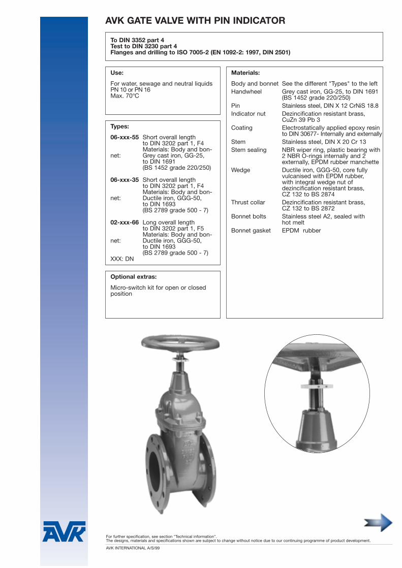
To DIN 3352 part 4Test to DIN 3230 part 4Flanges and drilling to ISO 7005-2 (EN 1092-2: 1997, DIN 2501)
Use:
For water, sewage and neutral liquids PN 10 or PN 16Max. 70°C
Optional extras:
Micro-switch kit for open or closed position
Types:
06-xxx-55 Short overall lengthto DIN 3202 part 1, F4Materials: Body and bon-
To DIN 3352 part 4Test to DIN 3230 part 4Flanges and drilling to ISO 7005-2 (EN 1092-2: 1997, DIN 2501)
1
2
3
4
5
6
7
8
9
10
11
12
13
14
15
Db
L
H
DhDt D
ds
For further specification, see section "Technical information".The designs, materials and specifications shown are subject to change without notice due to our continuing programme of product development.
AVK INTERNATIONAL A/S/99
To DIN 3352 part 4Test to DIN 3230 part 4Flanges and drilling to ISO 7005-2 (EN 1092-2: 1997, DIN 2501)
Use:
For water, sewage and neutral liquids PN 10 or PN 16Max. 70°C
Types:
06-xxx-20 Short overall lengthto DIN 3202 part 1, F4Materials: body and bonnet:Grey cast iron, GG-25,to DIN 1691 (BS 1452 grade 220/250)
06-xxx-76 Short overall lengthto DIN 3202 part 1, F4Materials: body and bonnet:Ductile iron, GGG-50, to DIN 1693 (BS 2789 grade 500 - 7)
02-xxx-76 Long overall lengthto DIN 3202 part 1, F5Materials: body and bonnet:Ductile iron, GGG-50,to DIN 1693 (BS 2789 grade 500 - 7)
XXX: DN
Materials:
Body and bonnet See the different "Types" to the leftHandwheel Grey cast iron, GG-25, to DIN 1691
To DIN 3352 part 4Test to DIN 3230 part 4Flanges and drilling to ISO 7005-2 (EN 1092-2: 1997, DIN 2501)
1
2
3
4
5
6
7
8
9
10
11
12
13
14
15
16
Db
L
H
ds
DhDt D
For further specification, see section "Technical information".The designs, materials and specifications shown are subject to change without notice due to our continuing programme of product development.
AVK INTERNATIONAL A/S/99
PN 10 or PN 16. To DIN 3352 part 4.Face to face dimension to DIN 3202 part 1, F4, Flanges and drilling to ISO 7005-2 (EN 1092-2: 1997, DIN 2501).Mounting flange and stem to ISO 5210, attachment type B3.
Use:
For water, sewage and neutral liquids tomax. 70°C
Test:
Hydraulic test to DIN 3230 part 4:Seat: PNBody: 1.5 x PNOperating torque test
Optional extras:
Adapter for output drive B1
DREHMO actuator, D59, D120,D200, D500
Materials:
Body and bonnet Ductile iron, GGG-50, to DIN 1693(BS 2789 grade 500 - 7 )
Mounting flange Steel st. 52.3Coating Electrostatically applied epoxy
resin to DIN 30677- Internally and externally
Stem Stainless steel, DIN X 20 Cr 13Stem sealing NBR wiper ring, 2 NBR O-rings
inside and 2 outside a plastic bearing, EPDM rubber manchette
Wedge Ductile iron, GGG-50, core fully vulcanised with EPDM rubber and having integral wedge nut of dezincification resistant brass, CZ 132 to BS 2874
Thrust collar Dezincification resistant brass, CZ 132 to BS 2872
Bonnet bolts Stainless steel A2, sealed with hot melt
PN 10 or PN 16. To DIN 3352 part 4.Face to face dimension to DIN 3202 part 1, F4, Flanges and drilling to ISO 7005-2 (EN 1092-2: 1997, DIN 2501).Mounting flange and stem to ISO 5210, attachment type B3.
bød
H1 H2
L
Dt Dh D
D5
D3
D4
D2
Drilling AHoles for socket cap boltsto ISO 5210(attachment to actuator)
PN 10 or PN 16. To DIN 3352 part 4.Face to face dimension to DIN 3202 part 1, F4, Flanges and drilling to ISO 7005-2 (EN 1092-2: 1997, DIN 2501).Mounting flange and stem to ISO 5210, attachment type B3.
DREHMO ACTUATOR 15/40
Type D59, D120, D200 and D500, for short-time dutyClass of enclosure IP67 to DIN 40050Output drive B3
H4D1
Actuator:Closing
Valve DN DREHMO speed H4 H5 D C1 C2 Weight kilosactuator sec. mm mm mm mm mm incl. valve
- Type D59: Torque span 20- 60 Nm, nominal current 1.3 A, max. current 1.7 A, starting current 4.3 AType D120: Torque span 40-120 Nm, nominal current 2.1 A, max. current 2.1 A, starting current 5.2 AType D200: Torque span 80-200 Nm, nominal current 2.1 A, max. current 2.2 A, starting current 5.2 AType D500: Torque span 150-500 Nm, nominal current 2.5 A, max. current 5.3 A, starting current 8.2 A
- Ambient temperature: -0° - +70°C- Speed: AVK recommends: DN 40-80: 40 turns/min., DN 100-300: 25 turns/min., DN 350-500: 10 turns/min.- Corrosion protection: Two-pack primer and two-pack micaceous iron paint (suitable for indoor and outdoor use)- Terminal plan for KD 102-5000-64:
control switches: - On/Off limit switch (defined area) for opening/closing direction- On/Off torque switch (resistance) for opening/closing direction- Indicator for opening/closing direction- Thermo switch, preventing overheating, automatic reset- Automatic space heater, preventing air moisture
- Test after mounting: Seat test to DIN 3230 part 4 - Operation: The actuator is operated by torque switching, but indicates error if the torque switches off the
actuator before the limit switch is activated.Special design: Terminal for indication and changes of the above standard design to be stated on ordering.
For special functions please enclose sized functional sketches.
Supply voltage is ALWAYS to be stated on inquiries or orders, e.g. 3 x 380V~, 50 Hz
For further specification, see section "Technical information".The designs, materials and specifications shown are subject to change without notice due to our continuing programme of product development.
AVK INTERNATIONAL A/S/99
AVK GATE VALVE PN 10 OR PN 16 55/30
To DIN 3352 part 4 / BS 5163 Type B. Stem sealing exchangeable under pressureFace to face dimension to EN 558-1: 1991 / DIN 3202 part 1, F5Flanges and drilling to ISO 7005-2 (EN 1092-2: 1997, DIN 2501)Gland flange to ISO 5210: 1991. Complete By-Pass with DN 80 valve
Use:
For water, neutral liquids and wastewater with max. 10% dry matter Max. 70°C
Tests:
Hydraulic test to DIN 3230 part 4:Seat: PNBody: 1.5 x PN
Operating torque test
Optional extras:
Stem capGearbox with stem capGearbox with handwheelGearbox with extension spindleElectric actuatorFlange adaptor (for DN 500-600)
Materials:
Body, bonnet and Ductile iron, GGG-50, to DIN 1693gland flange (BS 2789 grade 500 - 7)Coating Epoxy coating - internally and
To DIN 3352 part 4 / BS 5163 Type B. Stem sealing exchangeable under pressureFace to face dimension to EN 558-1: 1991 / DIN 3202 part 1, F5Flanges and drilling to ISO 7005-2 (EN 1092-2: 1997, DIN 2501)Gland flange to ISO 5210: 1991. Complete By-Pass with DN 80 valve
For further specification, see section "Technical information".The designs, materials and specifications shown are subject to change without notice due to our continuing programme of product development.
AVK INTERNATIONAL A/S/99
AVK POWERSAVER TM GATE VALVE PN 10 OR PN 16 55/35
Basic design to DIN 3352 part 4 / BS 5163 Type A, with a patented torque reducing featureFace to face dimension to EN 558-1: 1995 basic series 15 / DIN 3202 part 1, F5Flanges and drilling to ISO 7005-2 (EN 1092-2: 1997, DIN 2501)Gland flange to ISO 5210: 1991
Use:
For water, neutral liquids and wastewater with max. 10% dry matter Max. 70°C
For further technical information, see installation and main-tenance instruction.
Tests:
Hydraulic test to DIN 3230 part 4:Seat: PNBody: 1.5 x PN
Operating torque test
Optional extras:
Stem cap Handwheel Extension spindleBevel gearElectric actuatorFlange adaptor Complete By-Pass with DN 80 valve
Materials:
Body, bonnet Ductile iron, GGG-50, to DIN 1693and gland flange (BS 2789 grade 500 - 7)Coating Epoxy coating - internally and
Basic design to DIN 3352 part 4 / BS 5163 Type A, with a patented torque reducing featureFace to face dimension to EN 558-1: 1995 basic series 15 / DIN 3202 part 1, F5Flanges and drilling to ISO 7005-2 (EN 1092-2: 1997, DIN 2501)Gland flange to ISO 5210: 1991
For further specification, see section "Technical information".The designs, materials and specifications shown are subject to change without notice due to our continuing programme of product development.
AVK INTERNATIONAL A/S/99
To DIN 3352 part 4 and DIN 3230 part 4For fusion welded installation in PE-water pipes to BS 3284 (DIN 8074, DS 2119)
Use:
For water and neutral liquids to max. 70°CPE-pipe material to max. 20°C
Tests:
Valve Hydraulic test to DIN 3230 part 4:Seat: PN Body: 1.5 x PNOperating torque test
Optional extras:
HandwheelExtension spindleStem capFoundation of galvanized steel
Materials:
Body and bonnet Ductile iron, GGG-50, to DIN 1693(BS 2789 grade 500 - 7)
Coating Electrostatically applied epoxy resin to DIN 30677 - internally and exter-nally
Stem Stainless steel, DIN X 20 Cr 13Stem sealing NBR wiper ring, 2 NBR O-rings
inside and 2 outside a plastic bearing, EPDM rubber manchette
Wedge Ductile iron, GGG-50, core fullyvulcanised with EPDM rubber,with integral wedge nut ofdezincification resistant brass,CZ 132 to BS 2874
Thrust collar Dezincification resistant brass, CZ 132 to BS 2872
Bonnet bolts Stainless steel A2, sealed with hot melt
Bonnet gasket EPDM rubberSleeves St 52 to DIN 2448/1629Shrink hose Plastic to DIN 30672Pipes PE-water pipes to BS 3284
To DIN 3352 part 4 and DIN 3230 part 4For fusion welded installation in PE-water pipes to BS 3284 (DIN 8074, DS 2119)
1
2
3
4
5
6
7
8
9
10
11
12
13
14
15
H
D.ex.
F
L1
L
XX:10 = PE 80 - PN 1011 = PE 80 - PN 6.312 = PE 100 - PN 1013 = PE 100 - PN 6.316 = PE 100 - PN 16
For further specification, see section "Technical information".The designs, materials and specifications shown are subject to change without notice due to our continuing programme of product development.
AVK INTERNATIONAL A/S/99
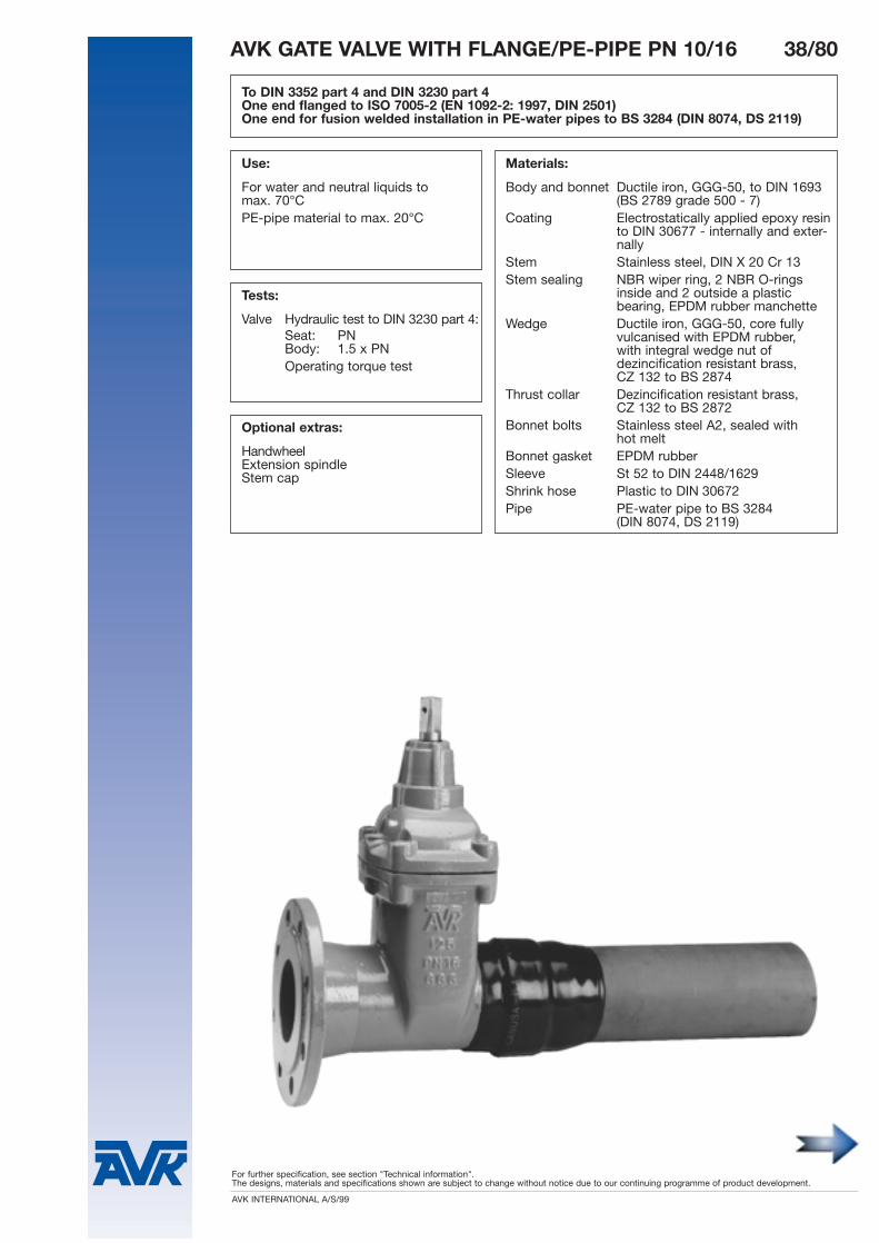
To DIN 3352 part 4 and DIN 3230 part 4One end flanged to ISO 7005-2 (EN 1092-2: 1997, DIN 2501)One end for fusion welded installation in PE-water pipes to BS 3284 (DIN 8074, DS 2119)
Use:
For water and neutral liquids to max. 70°CPE-pipe material to max. 20°C
Tests:
Valve Hydraulic test to DIN 3230 part 4:Seat: PN Body: 1.5 x PNOperating torque test
Optional extras:
HandwheelExtension spindleStem cap
Materials:
Body and bonnet Ductile iron, GGG-50, to DIN 1693(BS 2789 grade 500 - 7)
Coating Electrostatically applied epoxy resin to DIN 30677 - internally and exter-nally
Stem Stainless steel, DIN X 20 Cr 13Stem sealing NBR wiper ring, 2 NBR O-rings
inside and 2 outside a plastic bearing, EPDM rubber manchette
Wedge Ductile iron, GGG-50, core fullyvulcanised with EPDM rubber,with integral wedge nut ofdezincification resistant brass,CZ 132 to BS 2874
Thrust collar Dezincification resistant brass, CZ 132 to BS 2872
Bonnet bolts Stainless steel A2, sealed with hot melt
Bonnet gasket EPDM rubberSleeve St 52 to DIN 2448/1629Shrink hose Plastic to DIN 30672Pipe PE-water pipe to BS 3284
To DIN 3352 part 4 and DIN 3230 part 4One end flanged to ISO 7005-2 (EN 1092-2: 1997, DIN 2501)One end for fusion welded installation in PE-water pipes to BS 3284 (DIN 8074, DS 2119)
1
2
3
4
5
6
7
8
9
10
11 12 13 14 15
H
F
L2
L
D Dh
L1
ds
D.ex.
For further specification, see section "Technical information".The designs, materials and specifications shown are subject to change without notice due to our continuing programme of product development.
AVK INTERNATIONAL A/S/99
To DIN 3352 part 4 and BS 5163 Type AWith "Wavisafe" socket ends for PVC-pipes
Use:
For water, sewage and neutral liquids to max. 70°C
Tests:
Hydraulic test to DIN 3230 part 4:Seat: PNBody: 1.5 x PNOperation torque test
Optional extras:
HandwheelExtension spindleStem cap
Approvals:
KIWA - NL
Materials:
Body and bonnet Ductile iron, GGG-50, to DIN 1693(BS 2789 grade 500 - 7)
Coating *) Electrostatically applied epoxy resin to DIN 30677 - internally and exter-nally
Stem Stainless steel, DIN X 20 Cr 13Stem sealing NBR wiper ring, 2 NBR O-rings inside
and 2 outside a plastic bearing, EPDM rubber manchette
Wedge Ductile iron, GGG-50, core fullyvulcanised with EPDM rubber,with integral wedge nut ofdezincification resistant brass,CZ 132 to BS 2874
Thrust collar Dezincification resistant brass, CZ 132 to BS 2872
Bonnet bolts Stainless steel A2, sealed with hot melt
Bonnet gasket EPDM rubberSockets Fitted with SBR rubber "Wavisafe"
To DIN 3352 part 4 and BS 5163 Type AWith "Wavisafe" socket ends for PVC-pipes
1
2
3
4
5
6
7
8
9
10
11
12
13
LC A
E
F
H
For further specification, see section "Technical information".The designs, materials and specifications shown are subject to change without notice due to our continuing programme of product development.
AVK INTERNATIONAL A/S/99
To DIN 3352 part 4 With "Euro" socket ends for PVC-pipes
Use:
For water, sewage and neutral liquids to max. 70°C
Tests:
Hydraulic test to DIN 3230 part 4:Seat: PNBody: 1.5 X PNOperation torque test
Optional extras:
HandwheelExtension spindleStem capSupport bush
Materials:
Body and bonnet Ductile iron, GGG-50, to DIN 1693(BS 2789 grade 500 - 7)
Coating *) Electrostatically applied epoxy resin to DIN 30677 - internally and exter-nally
Stem Stainless steel, DIN X 20 Cr 13Stem sealing NBR wiper ring, 2 NBR O-rings inside
and 2 outside a plastic bearing, EPDM rubber manchette
Wedge Ductile iron, GGG-50, core fullyvulcanised with EPDM rubber,with integral wedge nut ofdezincification resistant brass,CZ 132 to BS 2874
Thrust collar Dezincification resistant brass, CZ 132 to BS 2872
Bonnet bolts Stainless steel A2, sealed with hot melt
Bonnet gasket EPDM rubberSockets Fitted with SBR rubber "Euro"
sealing rings to suit metric PVC-pipes(To be ordered separately)
*) Sealing rings for the sockets to be ordered separately
**) Socket modified
To DIN 3352 part 4 With "Euro" socket ends for PVC-pipes
1
2
3
4
5
6
7
8
9
10
11
12
13
LC A
E
F
H
For further specification, see section "Technical information".The designs, materials and specifications shown are subject to change without notice due to our continuing programme of product development.
AVK INTERNATIONAL A/S/99
AVK GATE VALVE PN 16 33/00
To DIN 3352 part 4With socket ends for cast iron pipes to DIN 28603
Use:
For water, sewage and neutral liquidsto max. 70°C
Tests:
Hydraulic test to DIN 3230 part 4:Seat: PNBody: 1.5 x PN
Operating torque test
Optional extras:
HandwheelExtension spindleStem capSocket sealing ring
Materials:
Body and bonnet Ductile iron, GGG-50, to DIN 1693(BS 2789 grade 500 - 7)
Coating Electrostatically applied epoxy resinto DIN 30677- externally.
Enamelled internally. Stem Stainless steel, DIN X 20 Cr 13Stem sealing NBR wiper ring, 2 NBR O-rings
inside and 2 outside a plastic bearing, EPDM rubber manchette
Wedge Ductile iron, GGG-50, core fullyvulcanised with EPDM rubber,with integral wedge nut ofdezincification resistant brass,CZ 132 to BS 2874
Thrust collar Dezincification resistant brass, CZ 132 to BS 2872
Bonnet bolts Stainless steel A2, sealed with hot melt
To DIN 3352 part 4With socket ends for cast iron pipes to DIN 28603
L
H
F
1
2
3
4
5
6
7
8
9
10
11
12
E
For further specification, see section "Technical information".The designs, materials and specifications shown are subject to change without notice due to our continuing programme of product development.
AVK INTERNATIONAL A/S/99
AVK GATE VALVE PN 16 32/10
To DIN 3352 part 4With spigot ends for asbestos cement pipes to ISO class 18
Use:
For water, sewage and neutral liquidsto max. 70°C
Tests:
Hydraulic test to DIN 3230 part 4:Seat: PNBody: 1.5 x PN
Operating torque test
Optional extras:
HandwheelExtension spindleStem cap
Materials:
Body and bonnet Ductile iron, GGG-50, to DIN 1693(BS 2789 grade 500 - 7)
Coating Electrostatically applied epoxy resinto DIN 30677 - Internally and externally
Stem Stainless steel, DIN X 20 Cr 13Stem sealing NBR wiper ring, 2 NBR O-rings
inside and 2 outside a plastic bearing, EPDM rubber manchette
Wedge Ductile iron, GGG-50, core fullyvulcanised with EPDM rubber,with integral wedge nut ofdezincification resistant brass,CZ 132 to BS 2874
Thrust collar Dezincification resistant brass, CZ 132 to BS 2872
Bonnet bolts Stainless steel A2, sealed with hot melt
To DIN 3352 part 4With spigot ends for asbestos cement pipes to ISO class 18
1
2
3
4
5
6
7
9
10
11
12
8
L
H
F
A
D.ex.
For further specification, see section "Technical information".The designs, materials and specifications shown are subject to change without notice due to our continuing programme of product development.
AVK INTERNATIONAL A/S/99
AVK GATE VALVE PN 16 32/40
To DIN 3352 part 4With spigot ends for cast iron pipes to ISO 2531
Use:
For water, sewage and neutral liquids tomax. 70°C
Tests:
Hydraulic test to DIN 3230 part 4:Seat: PNBody: 1.5 x PN
Operating torque test
Optional extras:
HandwheelExtension spindleStem capFlange adaptor
Materials:
Body and bonnet Ductile iron, GGG-50, to DIN 1693(BS 2789 grade 500 - 7)
Coating Electrostatically applied epoxy resin
to DIN 30677 - internally and externally
Stem Stainless steel, DIN X 20 Cr 13Stem sealing NBR wiper ring, 2 NBR O-rings
inside and 2 outside a plastic bearing, EPDM rubber manchette
Wedge Ductile iron, GGG-50, core fullyvulcanised with EPDM rubber,with integral wedge nut ofdezincification resistant brass,CZ 132 to BS 2874
Thrust collar Dezincification resistant brass, CZ 132 to BS 2872
Bonnet bolts Stainless steel A2, sealed with hot melt
To DIN 3352 part 4With spigot ends for cast iron pipes to ISO 2531
1
2
3
4
5
6
7
9
10
11
12
8
L
H
F
A
D.ex.
For further specification, see section "Technical information".The designs, materials and specifications shown are subject to change without notice due to our continuing programme of product development.
AVK INTERNATIONAL A/S/99
AVK GATE VALVE PN 16 32/70
To DIN 3352 part 4With spigot ends for cast iron pipes to ISO 2531
Use:
For water, sewage and neutral liquids tomax. 70°C
Tests:
Hydraulic test to DIN 3230 part 4:Seat: PNBody: 1.5 x PN
Operating torque test
Optional extras:
HandwheelExtension spindleStem capFlange adaptor
Materials:
Body and bonnet Ductile iron, GGG-50, to DIN 1693(BS 2789 grade 500 - 7)
Coating Electrostatically applied epoxy resin
to DIN 30677 - internally and externally
Stem Stainless steel, DIN X 20 Cr 13Stem sealing NBR wiper ring, 2 NBR O-rings
inside and 2 outside a plastic bearing, EPDM rubber manchette
Wedge Ductile iron, GGG-50, core fullyvulcanised with EPDM rubber,with integral wedge nut ofdezincification resistant brass,CZ 132 to BS 2874
Thrust collar Dezincification resistant brass, CZ 132 to BS 2872
Bonnet bolts Stainless steel A2, sealed with hot melt
To DIN 3352 part 4With spigot ends for cast iron pipes to ISO 2531
1
2
3
4
5
6
7
9
10
11
12
8
L
H
F
A
D.ex.
5. Service connection valves for water
6. Valves and fittings for gas
7. Fire hydrants
8. Check valves
9. Air valves
10. Butterfly valves and other valves
11. Flange adaptors and couplings
12. Tapping saddles and repair clamps
13. Accessories for valves
14. Technical information
15.
1. General company and product information
4
2. Flanged gate valves for water
3. Other gate valves for water
4. Combi valves
For further specification, see section "Technical information".The designs, materials and specifications shown are subject to change without notice due to our continuing programme of product development.
For further specification, see section "Technical information".The designs, materials and specifications shown are subject to change without notice due to our continuing programme of product development.
AVK INTERNATIONAL A/S/99
AVK COMBI-CROSS, 4 OUTLETS, PN 10 OR PN 16 18/70
To DIN 3352 part 4 Flanges and drilling to ISO 7005-2 (EN 1092-2: 1997, DIN 2501)
Use:
For water, sewage and neutral liquidsto max. 70°C
With facility for insertion/removal of amole in all dimensions through the ver-tical full bore outlet, having same DN as the valves
Test:
Hydraulic test to DIN 3230 part 4:
Seat: PNBody: 1.5 x PNOperating torque test
Materials:
Valve bonnets Ductile iron, GGG-50, to DIN 1693(BS 2789 grade 500 - 7)
Valve bodies DN 100-200:Ductile iron, GGG-50, to DIN 1693(BS 2789 grade 500 - 7)DN 250-300:Cast steel, GS-C25N, to DIN 17245
Coating Electrostatically applied epoxy resin to DIN 30677 - Internally and externally. The bayonet of the combi body is metallized to DS/ISO 2063 Zn 40 and NS 1975 Zn 40 on the joint face to the blank cap and flanged raising piece
Stem Stainless steel, DIN X 20 Cr 13Stem sealing NBR wiper ring, 2 NBR O-rings
inside and 2 outside a plastic bearing, EPDM rubber manchette
Wedge Ductile iron, GGG-50, core fullyvulcanised with EPDM rubber,with integral wedge nut ofdezincification resistant brass,CZ 132 to BS 2874
Thrust collar Dezincification resistant brass, CZ 132 to BS 2872
Bonnet bolts Stainless steel A2, sealed with hot melt
X: 0 = PN 10The upper 4 bolt holes on all flanges are metric threaded. Stud bolts can be factory fitted as an optional extra.
1 = PN 16 Stud bolts for DN 100: AVK no. 18-100-87000, total length 100 mm with 90 mm M16 threadStud bolts for DN 150/200: AVK no. 18-150-87000, total length 110 mm with 100 mm M20 thread
AVK COMBI-CROSS, 4 OUTLETS, PN 10 OR PN 16 18/70
To DIN 3352 part 4 Flanges and drilling to ISO 7005-2 (EN 1092-2: 1997, DIN 2501)
For further specification, see section "Technical information".The designs, materials and specifications shown are subject to change without notice due to our continuing programme of product development.
AVK INTERNATIONAL A/S/99
Use:
For water, sewage and neutral liquids tomax.70°C
With facility for insertion/removal of amole in all dimensions through the ver-tical full bore outlet, having same DN as the valves
Test:
Hydraulic test to DIN 3230 part 4:
Seat: PNBody: 1.5 x PNOperating torque test
Materials:
Valve bonnets Ductile iron, GGG-50, to DIN 1693(BS 2789 grade 500 - 7)
Valve bodies DN 100-200:Ductile iron, GGG-50, to DIN 1693(BS 2789 grade 500 - 7)DN 250-300:Cast steel, GS-C25N, to DIN 17245
Coating Electrostatically applied epoxy resinto DIN 30677 - Internally and externally. The bayonet of the combi body is metallized to DS/ISO 2063 Zn 40 and NS 1975 Zn 40 on the joint face to the blank cap and flanged raising piece
Stem Stainless steel, DIN X 20 Cr 13Stem sealing NBR wiper ring, 2 NBR O-rings
inside and 2 outside a plastic bearing, EPDM rubber manchette
Thrust collar Dezincification resistant brass, CZ 132 to BS 2872
Wedge Ductile iron, GGG-50, core fullyvulcanised with EPDM rubber,with integral wedge nut ofdezincification resistant brass,CZ 132 to BS 2874
Bonnet bolts Stainless steel A2, sealed with hot melt
X: 0 = PN 10 The upper 4 bolt holes on all flanges are metric threaded. Stud bolts can be factory fitted as an optional extra.
1 = PN 16 Stud bolts for DN 100: AVK no. 18-100-87000, total length 100 mm with 90 mm M16 threadStud bolts for DN 150/200: AVK no. 18-150-87000, total length 110 mm with 100 mm M20 thread
AVK COMBI-CROSS, 3-OUTLETS, PN 10 OR PN 16 18/80
To DIN 3352 part 4 Flanges and drillings to ISO 7005-2 (EN 1092-2: 1997, DIN 2501)
For further specification, see section "Technical information".The designs, materials and specifications shown are subject to change without notice due to our continuing programme of product development.
AVK INTERNATIONAL A/S/99
AVK BLANK BONNET FOR VALVE 18/72
Can be delivered factory mounted on the AVK Combi-Cross on requestPosition of blank bonnet and possible outlet is to be stated when ordering
Use:
For blanking valve outlets of the AVKCombi-Cross, for which no integratedvalve unit is required
Materials:
Blank bonnet Ductile iron, GGG-50 to DIN 1693(BS 2789 grade 500 - 7)
DN 100 with 1 1/2" outlet DN 150 and 200 with 2" outlet
Blank bonnetH H1 weight
DN mm mm kilos
100 93 241 4.8150 128 333 7.8200 138 427 11.5
AVK BLANK BONNET FOR VALVE 18/72
Can be delivered factory mounted on the AVK Combi-Cross on requestPosition of blank bonnet and possible outlet is to be stated when ordering
H1
H
B
A
D
A
B
For further specification, see section "Technical information".The designs, materials and specifications shown are subject to change without notice due to our continuing programme of product development.
AVK INTERNATIONAL A/S/99
AVK FLANGED RAISING PIECE, PN 10 OR PN 16 18/73
With bayonet couplingFlanges and drilling to ISO 7005-2 (EN 1092-2: 1997, DIN 2501)
Use:
For mounting on vertical outlet of theAVK Combi-Cross, for connection ofe.g. a fire hydrant.With facility for insertion/removal of a"mole".
Materials:
Flanged raising Ductile iron, GGG-50, to DIN 1693piece (BS 2789 grade 500 - 7)Coating Electrostatically applied epoxy
resin to DIN 30677 - Internally and externally. The flanged raising piece ismetallized to DS/ISO 2063 Zn 40 and NS 1975 Zn 40 on the joint face to the vertical outlet of the AVK Combi-Cross.
D Dh Dt H H1 ds Holes WeightRef. nos. DN mm mm mm mm mm mm PN 10 PN 16 kilos
With bayonet couplingFlanges and drilling to ISO 7005-2 (EN 1092-2: 1997, DIN 2501)
H
D
Dh
Dt
H1
ds
For further specification, see section "Technical information".The designs, materials and specifications shown are subject to change without notice due to our continuing programme of product development.
AVK INTERNATIONAL A/S/99
AVK BLANK CAP WITH LIFTING RING 18/74
Materials:
Blank cap Ductile iron, GGG-50, to DIN 1693(BS 2789 grade 500 - 7)
Coating Electrostatically applied epoxy resin to DIN 30677 - Internally and externally. The blank cap is metallizedto DS/ISO 2063 Zn 40 and NS 1975 Zn 40 on the joint face to the vertical outlet of the AVK Combi Cross.
Use:
For covering the vertical outlet of theAVK Combi-Cross
For further specification, see section "Technical information".The designs, materials and specifications shown are subject to change without notice due to our continuing programme of product development.
AVK INTERNATIONAL A/S/99
AVK BRASS SERVICE CONNECTION VALVE PN 16 16/0X
To DIN 3352 part 4With tensile resistant screw couplings for PE-pipes
Use:
For water and neutral liquids to max.70°CPE-pipe material to max. 20°C
Tests:
Hydraulic test to DIN 3230 part 4:Seat: PNBody: 1.5 x PN
Operating torque test
Types:
Norwegian T-type bayonet connector AVK standard bayonet connector
Optional extras for AVK standard type:
Stem capHandwheelExtension spindleStreet cover
Materials:
Body and bonnet Hot forged dezincification resistant brass, CZ 132 to BS 2872
Stem Stainless steel, DIN X 5 Cr Ni Mo17-12-2 (1.4401, EN 10088)
Stem sealing NBR wiper ring, 2 NBR O-rings
Wedge Dezincification resistant brass, CZ 132 to BS 2874 vulcanized with EPDM rubber
Thrust collar Dezincification resistant brass,CZ 132 to BS 2872
Bonnet sealing NBR rubberCoupling nut and Dezincification resistant brass, tension ring CZ 132 to BS 2872Sealing ring NBR rubber, ring of dezincification
resistant brass, CZ 132 to BS 2872
Series 16/05
Norwegian T-typeSeries 16/00
AVK BRASS SERVICE CONNECTION VALVE PN 16 16/0X
To DIN 3352 part 4With tensile resistant screw couplings for PE-pipes
Pipe L1 F mmRef. nos. Ref. nos. D.ex. L mm H AVK Norwegian Weight
AVK Standard Norwegian T-type DN mm mm PE mm standard T-type kilos
For further specification, see section "Technical information".The designs, materials and specifications shown are subject to change without notice due to our continuing programme of product development.
AVK INTERNATIONAL A/S/99
AVK BRASS SERVICE CONNECTION VALVE PN 16 16/2X
To DIN 3352 part 4With "PRK-System" for PE-pipes, PN 10
Use:
For water and neutral liquids to max. 70°CPE-pipe material to max. 20°C
Tests:
Hydraulic test to DIN 3230 part 4:Seat: PNBody: 1.5 x PN
Operating torque test
Types:
Norwegian T-type bayonet connector AVK standard bayonet connector
Optional extras for AVK standard type:
Stem capHandwheelExtension spindleStreet coverConnection for DN 20/25 mm PE pipes
Materials:
Body and bonnet Hot forged dezincification resistant brass, CZ 132 to BS 2872
Stem Stainless steel, DIN X 5 Cr Ni Mo17-12-2 (1.4401, EN 10088)
Stem sealing NBR wiper ring, 2 NBR O-rings
Wedge Dezincification resistant brass, CZ 132 to BS 2874 vulcanized with EPDM rubber
Thrust collar Dezincification resistant brass,CZ 132 to BS 2872
For further specification, see section "Technical information".The designs, materials and specifications shown are subject to change without notice due to our continuing programme of product development.
AVK INTERNATIONAL A/S/99
AVK SERVICE CONNECTION VALVE PN 16 16/50
To DIN 3352 part 4With tensile resistant socket joints for PE-pipes
Use:
For water and neutral liquids to max.70°CPE-pipe material to max. 20°C
Tests:
Hydraulic test to DIN 3230 part 4:Seat: PNBody: 1.5 x PN
Operating torque test
Optional extras:
HandwheelExtension spindleStem cap
Approvals:
ETA Danmark(in progress)
Materials:
Body, bonnet, POM (Polyoxymethylen)end adaptors andinsertStem Stainless steel, DIN X 5 CrNi 189Stem sealing NBR wiper ring,
For further specification, see section "Technical information".The designs, materials and specifications shown are subject to change without notice due to our continuing programme of product development.
AVK INTERNATIONAL A/S/99
AVK SERVICE CONNECTION VALVE WITH PE-PIPES PN 10 16/80
To DIN 3352 part 4 and DIN 3230 part 4For fusion welded installation in PE-water pipes to BS 3284 (DIN 8074, DS 2119)
Use:
For water and neutral liquids to max.70°CPE-pipe material to max. 20°C
Tests:
Hydraulic test to DIN 3230 part 4:Seat: PNBody: 1.5 x PN
Operating torque test
Optional extras:
HandwheelExtension spindleStem cap
Materials:
Body, bonnet, POM (Polyoxymethylen)end adaptors andinsertStem Stainless steel, DIN X 5 CrNi 189Stem sealing NBR wiper ring,
PE-pipes available in free lenght: 300 or 1000 mm.
AVK SERVICE CONNECTION VALVE WITH PE-PIPES PN 10 16/80
To DIN 3352 part 4 and DIN 3230 part 4For fusion welded installation in PE-water pipes to BS 3284 (DIN 8074, DS 2119)
1
2
3
4
5
6
7
9
8
10
11
12
13
F
H
L
D.ex.
1. Stem 8. Wedge2. NBR wiper ring 9. Body3. EPDM O-ring 10. End adaptor4. Collar insert 11. PE-pipe O-ring5. Thrust collar 12. Support bushing6. Insert 13. PE-pipe7. Bonnet
For further specification, see section "Technical information".The designs, materials and specifications shown are subject to change without notice due to our continuing programme of product development.
AVK INTERNATIONAL A/S/99
AVK SERVICE CONNECTION VALVE PN 16 03/00
To DIN 3352 part 4Internal thread
Use:
For water and neutral liquids to max.70°CPE-pipe material to max. 20°C
Tests:
Hydraulic test to DIN 3230 part 4:Seat: PNBody: 1.5 x PN
Operating torque test
Optional extras:
HandwheelExtension spindleStem capDN 25 and DN 32 available with a1/4" frost drain hole
Materials:
Body and bonnet Ductile iron, GGG-50, to DIN 1693(BS 2789 grade 420 - 12 min.)
Coating Electrostatically applied epoxy resinto DIN 30677 - Internally and externally
Stem Stainless steel, DIN X 20 Cr 13Stem sealing NBR wiper ring, 2 NBR O-rings
inside and 2 outside a plastic bearing, EPDM rubber manchette
Wedge Dezincification resistant brass, CZ 132 to BS 2874 vulcanized with EPDM rubber
Thrust collar Dezincification resistant brass, CZ 132 to BS 2872
Bonnet bolts Stainless steel A2, sealed with hot melt
For further specification, see section "Technical information".The designs, materials and specifications shown are subject to change without notice due to our continuing programme of product development.
AVK INTERNATIONAL A/S/99
AVK SERVICE CONNECTION VALVE PN 10 03/20
To DIN 3352 part 4For +GF+/PVP-System
Use:
For water and neutral liquids to max.70°CPE-pipe material to max. 20°C
Tests:
Hydraulic test to DIN 3230 part 4:Seat: PNBody: 1.5 x PN
Operating torque test
Optional extras:
HandwheelExtension spindleStem cap
Materials:
Body and bonnet Grey cast iron, GG-25, to DIN 1691(BS 1452 grade 220/250)
Coating Electrostatically applied epoxy resinto DIN 30677 - Internally and externally
Stem Stainless steel, DIN X 20 Cr 13Stem sealing NBR wiper ring, 2 NBR O-rings
inside and 2 outside a plastic bearing, EPDM rubber manchette
Wedge Dezincification resistant brass, CZ 132 to BS 2872 vulcanized with SBR rubber
Thrust collar Dezincification resistant brass, CZ 132 to BS 2872
Bonnet bolts Stainless steel A2, sealed with hot melt
For further specification, see section "Technical information".The designs, materials and specifications shown are subject to change without notice due to our continuing programme of product development.
AVK INTERNATIONAL A/S/99
AVK WATER METER VALVE PN 10 03/28
To DIN 3302 part 4Internal pipe thread
Use:
For water and neutral liquids to max.70°CPE-pipe material to max. 20°C
Tests:
Hydraulic test to DIN 3230 Seat: PNBody: 1.5 x PN
Optional extras:
Extension spindleStem cap1/4" frost drain hole
Materials:
Body and bonnet Ductile iron, GGG-40, to DIN 1693(BS 2789 grade 420 - 12 min.)
Coating Electrostatically applied epoxy resinto DIN 30677 - Internally and externally
Stem Stainless steel, DIN X 20 Cr 13Stem sealing NBR wiper ring, 2 NBR O-rings
inside and 2 outside a plastic bearing, NBR rubber manchette
Wedge Dezincification resistant brass, CZ 132 to BS 2874 vulcanized with EPDM rubber
Thrust collar Dezincification resistant brass, CZ 132 to BS 2872
Bonnet bolts Stainless steel A2, sealed with hot melt
For further specification, see section "Technical information".The designs, materials and specifications shown are subject to change without notice due to our continuing programme of product development.
AVK INTERNATIONAL A/S/99
AVK SERVICE CONNECTION VALVE PN 10 03/30
To DIN 3352 part 4With tensile resistant socket joints for PE-pipes
Use:
For water and neutral liquids to max.70°CPE-pipe material to max. 20°C
Tests:
Hydraulic test to DIN 3230 part 4:Seat: PNBody: 1.5 x PN
Operating torque test
Optional extras:
HandwheelExtension spindleStem cap
Approvals:
VA 1.51/DK 5958
Materials:
Body and bonnet Grey cast iron, GG-25, to DIN 1691(BS 1452 grade 220/250)
Coating Electrostatically applied epoxy resinto DIN 30677 - internally and
externallyStem Stainless steel, DIN X 20 Cr 13Stem sealing NBR wiper ring, 2 NBR O-rings
inside and 2 outside a plastic bearing, EPDM rubber manchette
Wedge Dezincification resistant brass, CZ 132 to BS 2872 vulcanized with EPDM rubber
Thrust collar Dezincification resistant brass, CZ 132 to BS 2872
Bonnet bolts Stainless steel A2, sealed with hot melt
Bonnet gasket EPDM rubberSockets Fitted with SBR rubber sealing rings
To DIN 3352 part 4With tensile resistant socket joints for PE-pipes
For further specification, see section "Technical information".The designs, materials and specifications shown are subject to change without notice due to our continuing programme of product development.
AVK INTERNATIONAL A/S/99
AVK SERVICE CONNECTION VALVE PN 10 03/40
To DIN 3352 part 4For side tappingOne end external thread, one end internal thread for drilling equipmentand with a tensile resistant socket joint for PE-pipes
Use:
For water and neutral liquids to max.70°CPE-pipe material to max. 20°C
Tests:
Hydraulic test to DIN 3230 part 4:Seat: PNBody: 1.5 x PN
Operating torque test
Optional extras:
HandwheelExtension spindleStem cap
Materials:
Body and bonnet Grey cast iron, GG-25, to DIN 1691(BS 1452 grade 220/250)
Coating Electrostatically applied epoxy resinto DIN 30677 - Internally and externally
Stem Stainless steel, DIN X 20 Cr 13Stem sealing NBR wiper ring, 2 NBR O-rings
inside and 2 outside a plastic bearing, EPDM rubber manchette
Wedge Dezincification resistant brass, CZ 132 to BS 2874 vulcanized with EPDM rubber
Thrust collar Dezincification resistant brass, CZ 132 to BS 2872
Bonnet bolts Zinc coated steel 8.8, sealed with hot melt
Bonnet gasket EPDM rubberSocket Fitted with a SBR rubber sealing
To DIN 3352 part 4For side tappingOne end external thread, one end internal thread for drilling equipmentand with a tensile resistant socket joint for PE-pipes
For further specification, see section "Technical information".The designs, materials and specifications shown are subject to change without notice due to our continuing programme of product development.
AVK INTERNATIONAL A/S/99
AVK SERVICE CONNECTION VALVE PN 10 03/65
To DIN 3352 part 4With tensile resistant screw couplings for PE-pipes
Use:
For water and neutral liquids to max.70°CPE-pipe material to max. 20°C
Tests:
Hydraulic test to DIN 3230 part 4:Seat: PNBody: 1.5 x PN
Operating torque test
Optional extras:
HandwheelExtension spindleStem cap
Materials:
Body and bonnet Ductile iron, GGG-40, to DIN 1693(BS 2789 grade 420 - 12 min.)
Coating Electrostatically applied epoxy resinto DIN 30677 - Internally and externally
Stem Stainless steel, DIN X 20 Cr 13Stem sealing NBR wiper ring, 2 NBR O-rings
inside and 2 outside a plastic bearing, EPDM rubber manchette
Wedge Dezincification resistant brass, CZ 132 to BS 2872 vulcanized with EPDM rubber
Thrust collar Dezincification resistant brass, CZ 132 to BS 2872
Bonnet bolts Stainless steel A2, sealed with hot melt
Bonnet gasket EPDM rubberCoupling nut and Dezincification resistant brass, tension ring CZ 132 to BS 2872Sealing ring NBR rubber, ring of dezincification
To DIN 3352 part 4With tensile resistant screw couplings for PE-pipes
For further specification, see section "Technical information".The designs, materials and specifications shown are subject to change without notice due to our continuing programme of product development.
AVK INTERNATIONAL A/S/99
AVK SERVICE CONNECTION VALVE PN 10 03/85
To DIN 3352 part 4One end with tensile resistant screw coupling for PE-pipes, one end external thread
Use:
For water and neutral liquids to max.70°CPE-pipe material to max. 20°C
Tests:
Hydraulic test to DIN 3230 part 4:Seat: PNBody: 1.5 x PN
Operating torque test
Optional extras:
HandwheelExtension spindleStem cap
Materials:
Body and bonnet Ductile iron, GGG-40, to DIN 1691(BS 2789 grade 420 - 12 min.)
Coating Electrostatically applied epoxy resinto DIN 30677 - Internally and externally
Stem Stainless steel, DIN X 20 Cr 13Stem sealing NBR wiper ring, 2 NBR O-rings
inside and 2 outside a plastic bearing, EPDM rubber manchette
Wedge Dezincification resistant brass, CZ 132 to BS 2872 vulcanized with EPDM rubber
Thrust collar Dezincification resistant brass, CZ 132 to BS 2872
Bonnet bolts Stainless steel A2, sealed with hot melt
Bonnet gasket EPDM rubberCoupling nut and Dezincification resistant brass, tension ring CZ 132 to BS 2872Sealing ring NBR rubber, ring of dezincification
To DIN 3352 part 4One end with tensile resistant screw coupling for PE-pipes, one end external thread
For further specification, see section "Technical information".The designs, materials and specifications shown are subject to change without notice due to our continuing programme of product development.
AVK INTERNATIONAL A/S/99
AVK SERVICE CONNECTION VALVE PN 10 03/90
To DIN 3352 part 4With »PRK-System« for PE-pipes
Use:
For water and neutral liquids to max.70°CPE-pipe material to max. 20°C
Tests:
Hydraulic test to DIN 3230 part 4:Seat: PNBody: 1.5 x PN
Operating torque test
Optional extras:
HandwheelExtension spindleStem cap
Materials:
Body and bonnet Ductile iron, GGG-40, to DIN 1693(BS 2789 grade 420 - 12 min.)
Coating Electrostatically applied epoxy resinto DIN 30677 - Internally and externally
Stem Stainless steel, DIN X 20 Cr 13Stem sealing NBR wiper ring, 2 NBR O-rings
inside and 2 outside a plastic bearing, EPDM rubber manchette
Wedge Dezincification resistant brass, CZ 132 to BS 2874 vulcanized with EPDM rubber
Thrust collar Dezincification resistant brass, CZ 132 to BS 2872
Bonnet bolts Stainless steel A2, sealed with hot melt
For further specification, see section "Technical information".The designs, materials and specifications shown are subject to change without notice due to our continuing programme of product development.
AVK INTERNATIONAL A/S/99
AVK SERVICE CONNECTION VALVE PN 10 03/95
To DIN 3352 part 4One end with »PRK-System« for PE-pipes, one end external thread
Use:
For water and neutral liquids to max.70°CPE-pipe material to max. 20°C
Materials:
Body and bonnet Ductile iron, GGG-40, to DIN 1691(BS 2789 grade 420 - 12 min.)
Coating Electrostatically applied epoxy resinto DIN 30677- Internally and externally
Stem Stainless steel, DIN X 20 Cr 13Stem sealing NBR wiper ring, 2 NBR O-rings
inside and 2 outside a plastic bearing, EPDM rubber manchette
Wedge Dezincification resistant brass, CZ 132 to BS 2874 vulcanized with EPDM rubber
Thrust collar Dezincification resistant brass, CZ 132 to BS 2872
Bonnet bolts Stainless steel A2, sealed with hot melt
To DIN 3352 part 4One end with »PRK-System« for PE-pipes, one end external thread
For further specification, see section "Technical information".The designs, materials and specifications shown are subject to change without notice due to our continuing programme of product development.
AVK INTERNATIONAL A/S/99
To DIN 3352 part 4 and DIN 3230 part 4For fusion welded installation in PE-water pipes to BS 3284 (DIN 8074, DS 2119)
Use:
For water and neutral liquids to max.70°CPE-pipe material to max. 20°C
Tests:
Valve Hydraulic test to DIN 3230 part 4:Seat: PN Body: 1.5 x PNOperating torque test
Optional extras:
HandwheelExtension spindleStem capFoundation
Materials:
Body and bonnet Ductile iron, GGG-50, to DIN 1693(BS 2789 grade 500 - 7)
Coating Electrostatically applied epoxy resin to DIN 30677 - internally and exter-nally
Stem Stainless steel, DIN X 20 Cr 13Stem sealing NBR wiper ring, 2 NBR O-rings
inside and 2 outside a plastic bearing, EPDM rubber manchette
Wedge Dezincification resistant brass, CZ 132 to BS 2874 vulcanized with EPDM rubber
Thrust collar Dezincification resistant brass, CZ 132 to BS 2872
Bonnet bolts Stainless steel A2, sealed with hot melt
Bonnet gasket EPDM rubberSleeves St 52 to DIN 2448/1629Shrink hose Plastic to DIN 30672Pipes PE-water pipes PN 10 to BS 3284
(DIN 8074, DS 2119)
AVK SERVICE CONNECTION VALVE WITH PE-PIPES PN 10 36/8X
AVK SERVICE CONNECTION VALVE WITH PE-PIPES PN 10 36/8X
To DIN 3352 part 4 and DIN 3230 part 4For fusion welded installation in PE-water pipes to BS 3284 (DIN 8074, DS 2119)
1
2
3
4
5
6
7
8
9
10
11
12
13
14
D.ex.
F
L1
L
H
7. Fire hydrants
8. Check valves
9. Air valves
10. Butterfly valves and other valves
11. Flange adaptors and couplings
12. Tapping saddles and repair clamps
13. Accessories for valves
14. Technical information
15.
1. General company and product information
6
2. Flanged gate valves for water
3. Other gate valves for water
4. Combi valves
5. Service connection valves for water
6. Valves and fittings for gas
For further specification, see section "Technical information".The designs, materials and specifications shown are subject to change without notice due to our continuing programme of product development.
AVK INTERNATIONAL A/S/99
AVK SERVICE CONNECTION VALVE PN 4 03/25
To DIN 3352 part 4Internal threadStem sealing exchangeable under pressure
Use:
For gas to max. 50°C
PE-pipe material to max. 20°C
Tests:Hydraulic test to DIN 3230 part 4:Seat: PN Body: 1.5 x PNAir test to DIN 3230 part 5: 1.1 x PN Operating torque test
Optional extras:
HandwheelExtension spindleStem cap
Approvals:
DVGW (PN 4)
Materials:
Body and bonnet Ductile iron, GGG-40, to DIN 1693(BS 2789 grade 420 -12 min.)
Coating Electrostatically applied epoxy resinto DIN 30677 - Internally and externally
Stem Stainless steel, DIN X 20 Cr 13Stem sealing NBR wiper ring, 4 NBR O-rings,
To DIN 3352 part 4Internal threadStem sealing exchangeable under pressure
For further specification, see section "Technical information".The designs, materials and specifications shown are subject to change without notice due to our continuing programme of product development.
AVK INTERNATIONAL A/S/99
To DIN 3437 and DIN 3230For fusion welded installation in steel pipes to DIN 2470 part 2Stem sealing exchangeable under pressure
Use:
For gas to min. -20°C max. 50°C
Tests:
Test to DIN 3230 part 5:Body: 0.5 bar air
1.5 x PN water1.1 x PN air - (PG3)
Seat: 0.5 bar air1.1 x PN air - (PG3)
Operating torque test
Optional extras:
HandwheelExtension spindleStem cap
Approvals:
DVGW
Materials:
Bonnet Ductile iron, GGG-50, to DIN 1693(BS 2789 grade 500 - 7)
Body Cast steel, GS-C25N, to DIN 17245Coating*) Electrostatically applied epoxy resin
to DIN 30677 - internally and exter-nally
Stem Stainless steel, DIN X 20 Cr 13Stem sealing NBR wiper ring, 4 NBR O-rings and
NBR rubber manchetteStem seal nut Dezincification resistant brass,
CZ 132 to BS 2874Wedge Ductile iron, GGG-50, core fully
encapsulated with NBR rubber,with integral wedge nut ofdezincification resistant brass,CZ 132 to BS 2874
Thrust collar Dezincification resistant brass,CZ 132 to BS 2872
Bonnet bolts Stainless steel A2 sealed with hot melt
Bonnet gasket NBR rubberSteel pipe ends Steel 35.8 to DIN 17175
*) Also available with polyurethane tar externally
To DIN 3437 and DIN 3230For fusion welded installation in steel pipes to DIN 2470 part 2Stem sealing exchangeable under pressure
1
2
3
4
5
6
7
8
9
10
11
12
13
D.ex.
L
H
F
S
For further specification, see section "Technical information".The designs, materials and specifications shown are subject to change without notice due to our continuing programme of product development.
AVK INTERNATIONAL A/S/99
AVK GATE VALVE PN 10 OR PN 16 02/70
To DIN 3352 part 4, stem sealing exchangeable under pressureFace to face dimension to DIN 3202 part 1, F5Flanges and drilling to ISO 7005-2 (EN 1092-2: 1997, DIN 2501)
Use:
For gas to max. 50°C
Tests:
Hydraulic test to DIN 3230 part 4:
Seat: PNBody: 1.5 x PN
Air test to DIN 3230 part 5: 1.1 x PNOperating torque test
Optional extras:
HandwheelExtension spindleStem cap
Approvals:
DVGW - Reg. No.: 91.01e397
Materials:
Body and bonnet Ductile iron, GGG-50, to DIN 1693(BS 2789 grade 500 - 7)
Coating Electrostatically applied epoxy resinto DIN 30677 - Internally and externally
Stem Stainless steel, DIN X 20 Cr 13Stem sealing NBR wiper ring, 4 NBR O-rings and
a NBR rubber manchetteStem seal nut Dezincification resistant brass,
CZ 132 to BS 2874Wedge Ductile iron, GGG-50, core fully
encapsulated with NBR rubberwith integral wedge nut ofdezincification resistant brass,CZ 132 to BS 2874
Thrust collar Dezincification resistant brass, CZ 132 to BS 2872
Bonnet bolts Stainless steel A2, sealed with hot melt
* Flanges drilled to DIN 2501 350 mm, having an increased (400 mm) bore.
AVK GATE VALVE PN 10 OR PN 16 02/70
To DIN 3352 part 4, stem sealing exchangeable under pressureFace to face dimension to DIN 3202 part 1, F5Flanges and drilling to ISO 7005-2 (EN 1092-2: 1997, DIN 2501)
Dt D
For further specification, see section "Technical information".The designs, materials and specifications shown are subject to change without notice due to our continuing programme of product development.
AVK INTERNATIONAL A/S/99
AVK GATE VALVE PN 10 OR PN 16 06/70
To DIN 3352 part 4. Stem sealing exchangeable under pressureFace to face dimension DIN 3202 part 1, F4Flanges and drilling to ISO 7005-2 (EN 1092-2: 1997, DIN 2501)
Use:
For gas to max. 50°C
Tests:Hydraulic test to DIN 3230 part 4:Seat: PN Body: 1.5 x PNAir test to DIN 3230 part 5: 1.1 x PN Operating torque test
Optional extras:
HandwheelExtension spindleStem cap
Materials:
Body and bonnet Ductile iron, GGG-50, to DIN 1693(BS 2789 grade 500 - 7)
Coating Electrostatically applied epoxy resinto DIN 30677 - Internally and externally
Stem Stainless steel, DIN X 20 Cr 13Stem sealing NBR wiper ring, 4 NBR O-rings
NBR rubber manchetteStem seal nut Dezincification resistant brass,
CZ 132 to BS 2874Wedge Ductile iron, GGG-50, core fully
encapsulated with NBR rubberwith integral wedge nut ofdezincification resistant brass,CZ 132 to BS 2874
Thrust collar Dezincification resistant brass, CZ 132 to BS 2872
Bonnet bolts Stainless steel A2, sealed with hot melt
In the sizes DN 250 and DN 300 the upper bolt holes in the flanges are metric threaded (M20 for PN 10 and M24 for PN 16).
AVK GATE VALVE PN 10 OR PN 16 06/70
To DIN 3352 part 4. Stem sealing exchangeable under pressureFace to face dimension DIN 3202 part 1, F4Flanges and drilling to ISO 7005-2 (EN 1092-2: 1997, DIN 2501)
1
2
3
4
5
6
7
9
10
11
12
8
L
H
F
ds
DDhDt
For further specification, see section "Technical information".The designs, materials and specifications shown are subject to change without notice due to our continuing programme of product development.
AVK INTERNATIONAL A/S/99
AVK TRANSITION FITTING PN 4 39/00
For connecting steel and PE-gas pipesFor fusion welded installation in PE-gas pipes max. working pressure 4 barOne end steel, one end PE-gas pipe connected by means of B.G.C. approved coupling
Use:
For gas to max. 20°C
Test:
Pipe joints air test to: 1.5 x PN-pipes
Approvals:
B.G.C./PS/PL3DS 2199 NO. 1064DVGW - VP600
Materials:
Steel-pipe St 37 to DIN 2448/1629PE-pipe PN 2.5 or PN 4 to B.G.C./PS/PL3
For connecting steel and PE-gas pipesFor fusion welded installation in PE-gas pipes max. working pressure 4 barOne end steel, one end PE-gas pipe connected by means of B.G.C. approved coupling
For further specification, see section "Technical information".The designs, materials and specifications shown are subject to change without notice due to our continuing programme of product development.
AVK INTERNATIONAL A/S/99
AVK TRANSITION FITTING PN 4 39/10
For connecting PE-gas pipes to flangesFor fusion welded installation in PE-gas pipes max. working pressure 4 barOne end flanged to ISO 7005-2 (EN 1092-2: 1997, DIN 2501) PN 10, one end PE-gas pipeconnected by means of B.G.C. approved coupling
Use:
For gas to max. 20°C
Tests:
Pipe joint air test to: 1.5 x PN-pipe
Approvals:
B.G.C./PS/PL3DS 2199 No. 1064DVGW - VP600
Materials:
Flange internal Ductile iron, GGG-50, to DIN 1693part (BS 2789 grade 500 - 7)Flange bolt ring St 37 to DIN 17100PE-pipe PN 2.5 or PN 4 to B.G.C./PS/PL2
For connecting PE-gas pipes to flangesFor fusion welded installation in PE-gas pipes max. working pressure 4 barOne end flanged to ISO 7005-2 (EN 1092-2: 1997, DIN 2501) PN 10, one end PE-gas pipeconnected by means of B.G.C. approved coupling
For further specification, see section "Technical information".The designs, materials and specifications shown are subject to change without notice due to our continuing programme of product development.
AVK INTERNATIONAL A/S/99
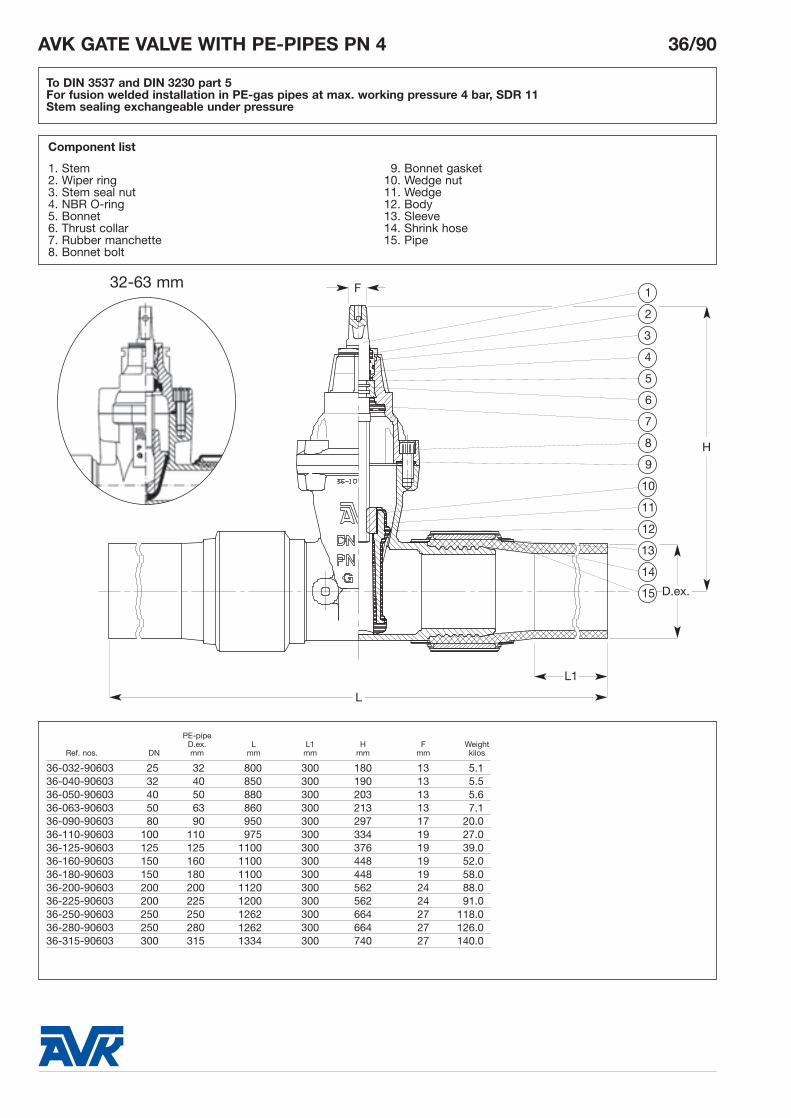
To DIN 3537 and DIN 3230 part 5For fusion welded installation in PE-gas pipes at max. working pressure 4 bar, SDR 11Stem sealing exchangeable under pressure
AVK GATE VALVE WITH PE-PIPES PN 4 36/90
Use:
For gas to max. 20°C
Tests:Valve: Hydraulic test to DIN 3230 part 4:Seat: PN Body: 1.5 x PNAir test to DIN 3230 part 5: 1.1 x PN
Operating torque test
Pipe joints air test to: 1.5 x PN-pipes
Optional extras:
HandwheelExtension spindleStem capFoundation
Approvals:
DVGW - VP 600DVGW - G 89 e 056 to DN 50/63 mm.DS 2199.1, 2 (No 1064A)
Materials:
Body and bonnet Ductile iron, GGG-50, to DIN 1693(BS 2789 grade 500 - 7)
Coating *) Electrostatically applied epoxy resinto DIN 30677 - Internally and externally
Stem Stainless steel, DIN X 20 Cr 13Stem sealing NBR wiper ring, 4 NBR O-rings,
NBR rubber manchetteStem seal nut Dezincification resistant brass,
CZ 132 to BS 2872Wedge**) Ductile iron, GGG-50, core fully
encapsulated with NBR rubberwith integral wedge nut ofdezincification resistant brass,CZ 132 to BS 2874
Thrust collar Dezincification resistant brass, CZ 132 to BS 2872
Bonnet bolts Stainless steel A2, sealed with hot melt
Bonnet gasket NBR rubberSleeves St 52 to DIN 2448/1629Shrink hose Plastic to DIN 30672Pipes PE-gas pipes to B.G.C./PS/PL2
(DS 2131.2)DVGW G 477, to DIN 8074, 8075
*) Also available with polyurethane tar externally
**) 32-63 mm: Dezincification resistant brass, CZ 132 to BS 2872 vulcanized with NBR rubber
To DIN 3537 and DIN 3230 part 5For fusion welded installation in PE-gas pipes at max. working pressure 4 bar, SDR 11Stem sealing exchangeable under pressure
For further specification, see section "Technical information".The designs, materials and specifications shown are subject to change without notice due to our continuing programme of product development.
AVK INTERNATIONAL A/S/99
AVK GATE VALVE WITH FLANGE/PE-PIPE PN 4 38/90
To DIN 3537 and DIN 3230 part 5One end flanged to ISO 7005-2 (EN 1092-2: 1997, DIN 2501)One end for fusion welded installation in PE-gas pipes at max. working pressure 4 bar, SDR 11Stem sealing exchangeable under pressure
Use:
For gas to max. 20°C
Tests:Valve Hydraulic test to DIN 3230 part 4:
Seat: PN Body: 1.5 x PNAir test to DIN 3230 part 5: 1.1 x PNOperating torque test
Pipe joints air test to: 1.5 x PN-pipes
Optional extras:
HandwheelExtension spindleStem cap
Materials:
Body and bonnet Ductile iron, GGG-50, to DIN 1693(BS 2789 grade 500 - 7)
Coating *) Electrostatically applied epoxy resinto DIN 30677 - Internally and externally
Stem Stainless steel, DIN X 20 Cr 13Stem sealing NBR wiper ring, 4 NBR O-rings,
NBR rubber manchetteStem seal nut Dezincification resistant brass,
CZ 132 to BS 2872Wedge Ductile iron, GGG-50, core fully
encapsulated with NBR rubber with integral wedge nut ofdezincification resistant brass, CZ 132 to BS 2874
Thrust collar Dezincification resistant brass, CZ 132 to BS 2872
Bonnet bolts Stainless steel A2, sealed with hot melt
Bonnet gasket NBR rubberSleeve St 52 to DIN 2448/1629Shrink hose Plastic to DIN 30672Pipe PE-gas pipe to B.G.C./PS/PL2
(DS 2131.2)DVGW G 477, to DIN 8074, 8075
*) Also available with polyurethane tar externally
Approvals:
DVGW: VP 600DVGW - G 89 e 056DS 2199.1, 2 (No 1064A)B.G.C. / PS / PL 3
To DIN 3537 and DIN 3230 part 5One end flanged to ISO 7005-2 (EN 1092-2: 1997, DIN 2501)One end for fusion welded installation in PE-gas pipes at max. working pressure 4 bar, SDR 11Stem sealing exchangeable under pressure
Flange PE-pipePN 10 D.ex. L L1 L2 H D Dh ds F Weight
Ref. nos. DN mm mm mm mm mm mm mm mm Holes mm kilos
For further specification, see section "Technical information".The designs, materials and specifications shown are subject to change without notice due to our continuing programme of product development.
AVK INTERNATIONAL A/S/99
AVK FIRE HYDRANT, TYPE B, PN 10 09/X0
Screw-down type, with Storz-couplingManual or automatic drainage Telescopic adjustable in height and 360° revolving outletFlange and drilling to ISO 7005-2 (EN 1092-2: 1997, DIN 2501)
Use:
For water and neutral liquids to max. 20°C
Tests:
Hydraulic test to DIN 3230 part 4:Seat : PNBody: 1.5 x PN
09/20: Aluminium, with UVresistant polyester, red RAL 3000
Isiflo coupling BrassFlange Ductile iron, GGG-50, with SBRadaptor rubber sealing and tensile ring
of acetal plasticPipe PE 80Foot bend and Grey cast iron, GG-25, withvalve body electrostatically applied epoxy
resin to DIN 30677 - internally and externally
Stem and disc Stainless steelDisc sealing SBR rubber
Optional extras:
Traffic flange for automatic typeCombi-flanges
AluminiumManual drainage Automatic drainage
T mm H WeightAVK ref. no. AVK ref. no. DN Type min - max mm Storz kilos Red colour
09-080-203021 09-080-201021 80 B 1050-1550 600 B - 3" 60 Ral 3000Manual drainage with ball valve Automatic drainage with ball valve
T mm H WeightAVK ref. no. AVK ref. no. DN Type min - max mm Storz kilos Red colour
09-080-20302110 09-080-20102110 80 B 1050-1550 600 B - 3" 60 Ral 3000
Cast ironManual drainage Automatic drainage
T mm H WeightAVK ref. no. AVK ref. no. DN Type min - max mm Storz kilos Red colour
09-080-303027 09-080-301027 80 B 1050-1550 600 B - 3" 75 Ral 3013
Manual drainage with ball valve Automatic drainage with ball valveT mm H Weight
AVK ref. no. AVK ref. no. DN Type min - max mm Storz kilos Red colour
09-080-30302710 09-080-30102710 80 B 1050-1550 600 B - 3" 75 Ral 3013
AVK FIRE HYDRANT, TYPE B, PN 10 09/X0
Screw-down type, with Storz-couplingManual or automatic drainage Telescopic adjustable in height and 360° revolving outletFlange and drilling to ISO 7005-2 (EN 1092-2: 1997, DIN 2501)
For further specification, see section "Technical information".The designs, materials and specifications shown are subject to change without notice due to our continuing programme of product development.
AVK INTERNATIONAL A/S/99
AVK FIRE HYDRANT, TYPE A, PN 10 09/50
Screw-down type with Storz-couplingManual or automatic drainage Telescopic adjustable in height and 360° revolving outletFlange and drilling to ISO 7005-2 (EN 1092-2: 1997, DIN 2501)
Use:
For water and neutral liquids to max. 20°C
Tests:
Hydraulic test to DIN 3230 part 4:Seat : PNBody: 1.5 x PN
Optional extras:
Combi-flanges
Approvals:
Danish Fire Inspection
Materials:
Hydrant Aluminium casting with polyester coating, red RAL 3000
Key operating nut Zinc coated grey cast iron, GG-25 Foot bend and Grey cast iron, GG-25, withvalve body electrostatically applied epoxy
resin to DIN 30677 - Internally and externally
Stem and disc Stainless steelDisc sealing SBR rubberPipe PE 80Storz-coupling AluminiumTensile coupling BrassFlange adaptor Ductile iron, GGG-50 with SBR
6. Flange adaptor7. Pipe8. Flange adaptor9. Valve body
10. Foot bend
Ref. nos. TAutomatic Manual mm H Weightdrainage drainage DN Type min - max mm Storz kilos
09-100-5020 09-100-5030 100 A 1050-1550 750 A - 4" 83
AVK FIRE HYDRANT, TYPE A, PN 10 09/50
Screw-down type with Storz-couplingManual or automatic drainage Telescopic adjustable in height and 360° revolving outletFlange and drilling to ISO 7005-2 (EN 1092-2: 1997, DIN 2501)
For further specification, see section "Technical information".The designs, materials and specifications shown are subject to change without notice due to our continuing programme of product development.
AVK INTERNATIONAL A/S/99
AVK FIRE HYDRANT PN 10 09/90
Gate-valve operatedAbove ground outlet through two Storz-Hosecoupling, automatic drainageTelescopic adjustable in height and 360° revolving outletFlange and drilling to ISO 7005-2 (EN 1092-2: 1997, DIN 2501)
Use:
For water and neutral liquids to max.20°C
Tests:
Hydraulic test to DIN 3230 part 4: 1.5 x PN
Optional extras:
Gate valve
Materials:
Foot bend Grey cast iron GG-25 to DIN 1691(BS 1452 grade 220/250)
10. Extension spindle *)11. Foundation *)12. Street-cover *)*) Has to be ordered separately
Tmm H Weight
Ref. nos. DN min-max mm Storz kilos
09-100-90 100 800-1300 870 4" 55
AVK FIRE HYDRANT PN 10 09/90
Gate-valve operatedAbove ground outlet through two Storz-Hosecoupling, automatic drainageTelescopic adjustable in height and 360° revolving outletFlange and drilling to ISO 7005-2 (EN 1092-2: 1997, DIN 2501)
For further specification, see section "Technical information".The designs, materials and specifications shown are subject to change without notice due to our continuing programme of product development.
AVK INTERNATIONAL A/S/99
To BS 750 type 2 - Compact modelScrew-down type with screwed 2 1/2" round thread outletInlet flange to EN 1092-2: 1997 DN 80 (ISO 7005-2, DIN 2501)Universally drilled PN 10/16 and to BS10 Table D/E - PN 10/16
Use:
For water and neutral liquids to max.70°CInsulation essential for installations sub-ject to temperatures of 0°C and lower.
Tests:
Hydraulic test to BS 750:Seat: 1.1 x PNBody: 1.5 x PN
Optional extras:
Fixed or loose stopperKite mark approvalAuto frost valveVarious outletsOutlet lock
Approvals:
WBS LISTEDKite mark (388 version)
Materials:
Body, bonnet, Ductile iron, GGG-50, to DIN 1693stopper (BS 2789 grade 500 - 7)Coating Electrostatically applied epoxy resin
to DIN 30677 - internally and exter-nally
Stem cap Cast iron, GG-25, to DIN 1691(BS 1452 grade 220/250)
Stem Stainless steel X 20 Cr 13388 version:Stainless steel BS 970 Gr 431 S29
Stem sealing High tensile brass, CZ 132 to BS 2874
O-rings NBR rubberStopper rubber EPDM rubberBolts Zinc-coated steel 8.8Safety device Stainless steelThrust collar, Dezincification resistant brassstopper nut CZ 132 to BS 2872Screwed outlet Gunmetal BS 1400 LG2 - C or nylonBody seat ring Gunmetal BS 1400 LG2 - CDust cap PE for screwed outletDrain plug Nylon
To BS 750 type 2 - Compact modelScrew-down type with screwed 2 1/2" round thread outletInlet flange to EN 1092-2: 1997 DN 80 (ISO 7005-2, DIN 2501)Universally drilled PN 10/16 and to BS10 Table D/E - PN 10/16
1
2
3
4
5
6
7
8
22
9
10
11
12
13
14
15
16
17
20
19
18
21
22
23
24
L1L
H
For further specification, see section "Technical information".The designs, materials and specifications shown are subject to change without notice due to our continuing programme of product development.
AVK INTERNATIONAL A/S/99
To BS 750 type 2 - Streamlined modelScrew-down type with screwed 2 1/2" round thread outletInlet flange to EN 1092-2: 1997 DN 80 (ISO 7005-2, DIN 2501)Universally drilled PN 10/16 and to BS10 Table D/E - PN 10/16
Use:
For water and neutral liquids to max.70°CInsulation essential for installations subject to temperatures of 0°C and lower.
Tests:
Hydraulic test to BS 750:Seat: 1.1 x PNBody: 1.5 x PN
Optional extras:
Fixed or loose stopperKite mark approvalAuto frost valveVarious outletsOutlet lock
Approvals:
WBS LISTEDKite mark (389 version)
Materials:
Body, bonnet, Ductile iron, GGG-50, to DIN 1693stopper (BS 2789 grade 500 - 7)Coating Electrostatically applied epoxy resin
to DIN 30677 - internally and exter-nally
Stem cap Cast iron, GG-25, to DIN 1691(BS 1452 grade 220/250)
Stem Stainless steel X 20 Cr 13389 version:Stainless steel BS 970 Gr 431 S29
Stem sealing High tensile brass, CZ 132 to BS 2874
O-rings NBR rubberStopper rubber EPDM rubberBolts Zinc-coated steel 8.8Safety device Stainless steelThrust collar, Dezincification resistant brassstopper nut CZ 132 to BS 2872Screwed outlet Gunmetal BS 1400 LG2 - C or nylonBody seat ring Gunmetal BS 1400 LG2 - CDust cap PE for screwed outletDrain plug Nylon
To BS 750 type 2 - Streamlined modelScrew-down type with screwed 2 1/2" round thread outletInlet flange to EN 1092-2: 1997 DN 80 (ISO 7005-2, DIN 2501)Universally drilled PN 10/16 and to BS10 Table D/E - PN 10/16
1
2
3
4
5
6
7
8
9
10
22
11
12
13
14
15
16
17
18
19
20
21
22
23
24
L1L
H
For further specification, see section "Technical information".The designs, materials and specifications shown are subject to change without notice due to our continuing programme of product development.
AVK INTERNATIONAL A/S/99
AVK UNDERGROUND FIRE HYDRANT PN 16 29/00
To BS 750 type 2Screw-down type with bayonet, screwed 2 1/2" London round thread or instantaneous outletFlange and drilling to ISO 7005-2 (EN 1092-2: 1997, DIN 2501)
Use:
For water and neutral liquids to max.70°C
Tests:
Hydraulic test to BS 750:Seat: 1.1 x PNBody: 1.5 x PNOperating torque test
Approvals:
WBS-approved
Materials:
Body, bonnet Grey cast iron, GG-25, to DIN 1691disc, stem cap (BS 1452 grade 220/250)and bayonet outlet Coating Electrostatically applied epoxy resin
to DIN 30677 - Internally and externally
Stem Stainless steel DIN X 20 Cr 13Stem sealing NBR wiper ring, 2 NBR O-rings
inside and 2 outside a plastic bearing
Bonnet gasket NBR O-ringDisc sealing ring EPDM rubberBolts, nuts and Zinc-coated steel 8.8washerThrust collar, Dezincification resistant brass, seat rings and CZ 132 to BS 2872disc nutScrewed and Gunmetal BS 1400 LG2 - C or nyloninstantaneous outletDust cap PE for screwed outletPlug Nylon
To BS 750 type 2Screw-down type with bayonet, screwed 2 1/2" London round thread or instantaneous outletFlange and drilling to ISO 7005-2 (EN 1092-2: 1997, DIN 2501)
For further specification, see section "Technical information".The designs, materials and specifications shown are subject to change without notice due to our continuing programme of product development.
AVK INTERNATIONAL A/S/99
AVK UNDERGROUND FIRE HYDRANT PN 16 29/60
To BS 750 type 1 with gate valve to BS 5163With bayonet, screwed 2 1/2" London round thread or instantaneous outletFlange and drilling to ISO 7005-2 (EN 1092-2: 1997, DIN 2501)
Use:
For water and neutral liquids to max. 70° C
Materials:
Duck foot bend Grey cast iron, GG-25, to DIN 1691(BS 1452 grade 220/250)
Dust cap PE for screwed outletScrewed and Gunmetal BS 1400 LG2 -C or nyloninstantaneousoutletBayonet outlet Grey cast iron, GG-25, to DIN 1691
Hydraulic test to BS 750:Seat: 1.1 x PNBody: 1.5 x PNOperating torque test
Optional extras:
HandwheelExtension spindle
AVK UNDERGROUND FIRE HYDRANT PN 16 29/60
To BS 750 type 1 with gate valve to BS 5163With bayonet, screwed 2 1/2" London round thread or instantaneous outletFlange and drilling to ISO 7005-2 (EN 1092-2: 1997, DIN 2501)
Drain plug Automatic valve DN mm mm mm (valve incl.)
29-080-60 29-080-50 80 408 206 390 44
Other options available on request
For further specification, see section "Technical information".The designs, materials and specifications shown are subject to change without notice due to our continuing programme of product development.
AVK INTERNATIONAL A/S/99
AVK FIRE HYDRANT PN 16 30/30
To NS 373Flange and drilling to ISO 7005-2 (EN 1092-2:1997, DIN 2501)
Use:
For water and neutral liquids to max.70°C
Tests:
Hydraulic test to DIN 3230 part 4:Seat: PNBody: 1.5 x PN
Materials:
Body and Grey cast iron, GG-25, to DIN 1691bayonet bonnet (BS 1452 grade 220/250)Coating Electrostatically applied epoxy resin
H D Dh ds WeightRef. nos. DN mm mm mm mm Holes kilos
30-100-30 100 208 220 180 18 8 12.4
AVK FIRE HYDRANT PN 16 30/30
To NS 373Flange and drilling to ISO 7005-2 (EN 1092-2:1997, DIN 2501)
H
9. Air valves
10. Butterfly valves and other valves
11. Flange adaptors and couplings
12. Tapping saddles and repair clamps
13. Accessories for valves
14. Technical information
15.
1. General company and product information
8
2. Flanged gate valves for water
3. Other gate valves for water
4. Combi valves
5. Service connection valves for water
6. Valves and fittings for gas
7. Fire hydrants
8. Check valves
For further specification, see section "Technical information".The designs, materials and specifications shown are subject to change without notice due to our continuing programme of product development.
AVK INTERNATIONAL A/S/99
To BS 5153: 1974 (1991)Resilient seatedFace to face dimension to BS 5153: 1974 (1991) shortFlanges and drilling to ISO 7005-2 (EN 1092-2: 1997, DIN 2501)
Use:
For potable water and sewage to max. 70°C
Tests:
Hydraulic test to BS 5153 : 1974 (1991)Seat: 1.1 x PNBody: 1.5 x PN
Optional extras:
Lever and weight:Mounted RHS as standard - can bemounted LHS on requestTapping plug
Additional information:
See technical data sheet for series 41
Materials:
Body, bonnet, Ductile iron, GGG-50, to DIN 1693 weight and hinge (BS 2789 grade 500-7)Coating Electrostatically applied epoxy resin to
DIN 30677 - Internally and externallyShaft Stainless steel to BS 431S29Bonnet gasket EPDM rubberBushing Brass, CZ 132 to BS 2874Hexagon bolt, Stainless steel AISI 304 washer and pinResilient EPDM rubber with a steel insert toseated disc BS 4360 : 1979 43BLever Steel 43B to BS 4360:1979
To BS 5153: 1974 (1991)Resilient seatedFace to face dimension to BS 5153: 1974 (1991) shortFlanges and drilling to ISO 7005-2 (EN 1092-2: 1997, DIN 2501)
AVK SWING CHECK VALVE PN 10 OR PN 16 41/25
10987654321 11 12
A°
H
L
Dt Dh D
ds
13 14 15 16 17 18 19 20
For further specification, see section "Technical information".The designs, materials and specifications shown are subject to change without notice due to our continuing programme of product development.
AVK INTERNATIONAL A/S/99
To BS 5153 : 1974 (1991)Metal seatedFace to face dimension BS 5153 : 1974 (1991) shortFlanges and drilling to ISO 7005-2 (EN 1092-2: 1997, DIN 2501)
Use:
For potable water and sewage to max. 70°C
Tests:
Hydraulic test to BS 5153 : 1974 (1991)Seat: 1.1 x PNBody: 1.5 x PN
Optional extras:
Lever and weight: Mounted RHS as standard - can bemounted LHS on requestTapping plug
Additional information:
See technical data sheet for series 41
Materials:
Body, bonnet, Ductile iron, GGG-50, to DIN 1693 weight and hinge (BS 2789 grade 500-7) Coating Electrostatically applied epoxy resin to
DIN 30677 - Internally andexternallyShaft Stainless steel to BS 431S29Bonnet gasket EPDM rubberBushing Dezincification resistant brass
CZ 132 to BS 2874Washer and pin Stainless steel AISI 304 Seat ring Gunmetal, BS 1400 LG2Metal seated EPDM rubber with a steel insert disc to BS 4360 : 1979 43B
and a disc seat ring of Gunmetal, BS 1400 LG2
Lever Steel to BS 4360:1979 43BHexagon bolt Stainless steel A2
To BS 5153 : 1974 (1991)Metal seatedFace to face dimension BS 5153 : 1974 (1991) shortFlanges and drilling to ISO 7005-2 (EN 1092-2: 1997, DIN 2501)
AVK SWING CHECK VALVE PN 10 OR PN 16 41/30
10987654321 11 12 13
A°
H
L
Dt Dh D
ds
14 15 16 17 18 19 20 21
For further specification, see section "Technical information".The designs, materials and specifications shown are subject to change without notice due to our continuing programme of product development.
AVK INTERNATIONAL A/S/99
Resilient seatedFace to face dimension to DIN 3202-F6Flanges and drilling to ISO 7005-2 (EN 1092-2: 1997, DIN 2501)
Use:
For potable water and sewage to max. 70°C
Tests:
Hydraulic test to BS 5153 : 1974 (1991)Seat: PNBody: 1.5 x PN
Optional extras:
Lever and counterweightLimit-switchTapping plug
Additional information:
See technical data sheet for series 41
Materials:
Body, bonnet, Ductile iron, GGG-50, to DIN 1693 weight and hinge (BS 2789 grade 500-7)Coating Electrostatically applied epoxy resin to
DIN 30677 - Internally andexternallyShaft Stainless steel to Werkstnr. 1.40S7
(BS 431S29)Bonnet gasket EPDM rubberBushing Brass, CZ 132 to BS 2874Hexagon bolt, Stainless steel A2 washer and pinResilient EPDM rubber with a steel insert toseated disc EN 10113:1990 (BS 4360:1990)Lever Steel, EN 10113:1990
For further specification, see section "Technical information".The designs, materials and specifications shown are subject to change without notice due to our continuing programme of product development.
AVK INTERNATIONAL A/S/99
Metal seatedFace to face dimension to DIN 3202-F6Flanges and drilling to ISO 7005-2 (EN 1092-2: 1997, DIN 2501)
Use:
For potable water and sewage to max. 70°C
Tests:
Hydraulic test to BS 5153 : 1974 (1991)Seat: 1.1 x PNBody: 1.5 x PN
Optional extras:
Lever and counterweightLimit-switchTapping plug
Additional information:
See technical data sheet for series 41
Materials:
Body, bonnet, Ductile iron, GGG-50, to DIN 1693 weight and hinge (BS 2789 grade 500-7) Coating Electrostatically applied epoxy resin to
DIN 30677 - Internally andexternallyShaft Stainless steel to
Werkst. No. 1.4057 (BS 431S29)Bonnet gasket EPDM rubberBushing Brass, CZ 132 to BS 2874Hexagon bolt, Stainless steel A2 washer and pinMetal seated EPDM rubber with a steel insert disc to BS 4360:1979 43B
and a seat ring of dezincification resistant brass CZ 132 to BS
For further specification, see section "Technical information".The designs, materials and specifications shown are subject to change without notice due to our continuing programme of product development.
AVK INTERNATIONAL A/S/99
AVK BALL CHECK VALVE PN 10 53/3X
Designed to LGA standardsFace to face dimension to DIN 3202-F6Flanges and drilling to ISO 7005-2 (BS EN 1092-2: 1997, DIN 2501)
Use:
For water and sewage to max. 70°C.
Materials:
Body and Ductile iron, GGG-40 to DIN 1693 cover (BS 2789)Coating Electrostatically applied epoxy
resin to DIN 30677Cover gasket NBR O-ringBall DN 32-100: Aluminium,
The patented design reduces the pressure loss considerablyCmH2O
L
1
2
3
4
5
Dt D
Series 53/35
DN
H
cao l/s 10 20 30 40 50 60 70 L/S
160
140
120
100
80
60
40
20
0
DN100
10. Butterfly valves and other valves
11. Flange adaptors and couplings
12. Tapping saddles and repair clamps
13. Accessories for valves
14. Technical information
15.
1. General company and product information
9
2. Flanged gate valves for water
3. Other gate valves for water
4. Combi valves
5. Service connection valves for water
6. Valves and fittings for gas
7. Fire hydrants
8. Check valves
9. Air valves
For further specification, see section "Technical information".The designs, materials and specifications shown are subject to change without notice due to our continuing programme of product development.
AVK INTERNATIONAL A/S/99
Single acting - small orificeThreaded BSP 1"
Use:
Potable or untreated water (not sewa-ge) to max. 90°CWorking pressure: min. 0.2 bar
max. 16 bar
Tests:
Hydraulic test: 1.5 x PN
Options:
Brass base to BS 2874BSP thread 1/2", 3/4"NPT thread 1"
Orifice size:
12 mm2
Materials:
Body, Reinforced nylonclamping keyRolling seal EPDM rubberFloat Foamed polypropyleneO-ring BUNA - NBase Reinforced nylon
AVK AUTOMATIC AIR VALVE PN 16 701/10
AVK AUTOMATIC AIR VALVE PN 16 701/10
Component list:
1. Body2. Rolling seal3. Clamping key4. Float5. O-ring6. Base
For further specification, see section "Technical information".The designs, materials and specifications shown are subject to change without notice due to our continuing programme of product development.
AVK INTERNATIONAL A/S/99
Single acting - small orificeThreaded BSP 1" male adaptor
Use:
Potable or untreated water (not sewa-ge) to max. 90°CWorking pressure: min. 0.2 bar
max. 16 bar
Tests:
Hydraulic test: 1.5 x PN
Options:
1/2" or 3/4" BSP threaded male adap-tor NPT threaded male adaptors
3/4"- 1" up to 100 bar
Orifice size:
0.8 mm2
Materials:
Body Cast iron, GG-25, to DIN 1691Coating Blue epoxy Basket PolypropyleneFloat Rubber coated polycarbonateCover and Brass CZ 132 to BS 1400nozzleAdaptor Brass CZ 132 to BS 2874O-ring BUNA - NBolt assembly Galvanized steel 4.6Drainage elbow Brass (1/4" BSP)
AVK AUTOMATIC AIR VALVE PN 16 701/20
AVK AUTOMATIC AIR VALVE PN 16 701/20
A B WeightRef. nos. DN BSP mm mm kilos
701-032-2091 25 1" 132,5 199 3.5
Single acting - small orificeThreaded BSP 1" male adaptor
For further specification, see section "Technical information".The designs, materials and specifications shown are subject to change without notice due to our continuing programme of product development.
AVK INTERNATIONAL A/S/99
Single acting - large orificeInlet flange to ISO 7005-2 (EN 1092-2: 1997, DIN 2501) or 2" BSP thread
Use:
Potable or untreated water (not sewa-ge) to max. 90°CWorking pressure: min. 0.2 bar
max. 16 bar
Tests:
Hydraulic test: 1.5 x PN
Options:
Isolating gate valve series 06Isolating butterfly valves series 75
Available up to PN 100
Orifice sizes:
DN 50 794 mm2
DN 80 1809 mm2
DN 100 3317 mm2
DN 150 17662 mm2
DN 200 17662 mm2
Materials:
Body, cover Cast iron, GG-25, to DIN 1691Coating Blue epoxy Basket DN 50: PolypropyleneSeat EPDM on bronzeFloat DN 50-100: Polycarbonate
DN 150-200: Stainless steelO-ring BUNA - NPlug Brass CZ 132 to BS 2874Bolt assembly Galvanized steel 4.6
For further specification, see section "Technical information".The designs, materials and specifications shown are subject to change without notice due to our continuing programme of product development.
AVK INTERNATIONAL A/S/99
Double acting - double orificeThreaded BSP 2"
Use:
Potable or untreated water (not sewa-ge) to max. 90°CWorking pressure: min. 0.2 bar
max. 16 bar
Tests:
Hydraulic test: 1.5 x PN
Options:
Brass base to BS 2874NPT thread
Also available in GG-25
Orifice sizes:
Automatic: 12 mm2
Kinetic: 804 mm2
Materials:
Body, base, Reinforced nylonclamping key,seal supportScrew Stainless steel AISI 303Rolling seal EPDM rubberFloat Foamed polypropyleneO-ring BUNA - NDrainage elbow Polypropylene
AVK COMBINATION AIR VALVE PN 16 701/40
AVK COMBINATION AIR VALVE PN 16 701/40
Component list:
1. Body 6. Clamping key2. Screw 7. Float3. Rolling seal 8. O-ring4. Seal support 9. Base5. Drainage elbow (1 1/2" BSP-female)
For further specification, see section "Technical information".The designs, materials and specifications shown are subject to change without notice due to our continuing programme of product development.
AVK INTERNATIONAL A/S/99
Double acting - double orificeInlet flange to ISO 7005-2 (EN 1092-2: 1997, DIN 2501) or 2" BSP thread
Use:
Potable or untreated water (not sewa-ge) to max. 90°CWorking pressure: min. 0.2 bar
max. 16 bar
Tests:
Hydraulic test: 1.5 x PN
Options:
Isolating gate valve series 06Isolating butterfly valves series 75
Available up to PN 100
Orifice sizes:
DN Automatic Kinetic 50 12 mm2 794 mm2
80 12 mm2 1809 mm2
100 12 mm2 3317 mm2
150 12 mm2 17662 mm2
200 12 mm2 17662 mm2
Materials:
Automatic valve:Body, Reinforced nylonclamping keyRolling seal EPDM rubberFloat Foamed polypropyleneO-ring BUNA - N Base Brass to BS 2874
Kinetic valve:Body, cover Cast iron, GG-25, to DIN 1691Coating Blue epoxy Basket DN 50: PolypropyleneSeat EPDM on bronzeFloat DN 50-100: Polycarbonate
DN 150-200: Stainless steel 304LO-ring BUNA - N Bolt assembly Galvanized steel 4.6
AVK COMBINATION AIR VALVE PN 16 701/50
DN 50
AVK COMBINATION AIR VALVE PN 16 701/50
Component list:
1. Body, automatic 8. Seat2. Rolling seal 9. O-ring3. Clamping key 10. Bolt assembly4. Float 11. Float5. O-ring 12. Basket6. Base 13. Body, kinetic7. Cover
Double acting - double orificeInlet flange to ISO 7005-2 (EN 1092-2: 1997, DIN 2501) or 2" BSP thread
1
2
3
4
5
6
7
D
B C
0
10
50 200
20
100 150
Automatic air valveA
Flow M3/h
Pre
ssur
e B
ar
Kinetic air valve
8
10
11
12
13
9
100
0.1
200 1,000 2,000 10,000 20,0000
0.2
0.3
0.4
0.5
6” 8”4”3”2”
0.6
0.7
0.8
OUTFLOW
Flow m3/h
Pre
ssur
e B
ar
-100
-0.1
-200-1,000-2,000-10,000-20,0000
-0.2
-0.3
-0.4
-0.56” 8”4”3”2”
0
INFLOWFlow m3/h
Pressure B
ar
Flow M3/h
Pre
ssur
e B
ar
Pressure B
ar
Outflow
Outflow
Inflow
Air discharge
8" 6" 4" 3" 2"
Flow M3/h
For further specification, see section "Technical information".The designs, materials and specifications shown are subject to change without notice due to our continuing programme of product development.
AVK INTERNATIONAL A/S/99
Double actingInlet flange to ISO 7005-2 (EN 1092-2: 1997, DIN 2501) or 2" BSP thread
Use:
Potable or untreated water (not sewa-ge) to max. 90°CWorking pressure: min. 0.2 bar
max. 16 bar
Tests:
Hydraulic test: 1.5 x PN
Options:
Isolating gate valve series 06Isolating butterfly valves series 75
Available up to PN 100
Orifice sizes:
DN Automatic Kinetic50 0.8 mm2 794 mm2
80 0.8 mm2 1809 mm2
100 0.8 mm2 3317 mm2
150 0.8 mm2 17662 mm2
200 0.8 mm2 17662 mm2
Materials:
Automatic valve:Body Cast iron, GG-25, to DIN 1691Coating Blue epoxyScrew, Polypropyleneprotection cover,basketCover and nozzle Brass CZ 132 to BS 1400Float Rubber coated polycarbonateAdaptor Brass CZ 132 to BS 2874O-ring BUNA - NBolt, nut Galvanized steel 4.6
Kinetic valve:Body, cover Cast iron, GG-25, to DIN 1691Coating Blue epoxy Basket DN 50: PolypropyleneSeat EPDM on bronzeSeal EPDMFloat DN 50-100: Polycarbonate
Double actingInlet flange to ISO 7005-2 (EN 1092-2: 1997, DIN 2501) or 2" BSP thread
1
2
3
4
5
6
7
8
9
10
12
11
13
14
15
C
B
A
0
10
5 �
20
10�
Automatic air valve
Outflow
Air discharge
Kinetic air valve
100
0.1
200 1,000 2,000 10,000 20,0000
0.2
0.3
0.4
0.5
6” 8”4”3”2”
0.6
0.7
0.8
OUTFLOW
Flow M3/h
Pre
ssur
e B
ar
Flow M3/h
Pre
ssur
e B
ar
Outflow
-100
-0.1
-200-1,000-2,000-10,000-20,0000
-0.2
-0.3
-0.4
-0.56” 8”4”3”2”
0
INFLOWFlow m3/h
Pressure B
arP
ressure Bar
8" 6" 4" 3" 2"
InflowFlow M3/h
For further specification, see section "Technical information".The designs, materials and specifications shown are subject to change without notice due to our continuing programme of product development.
AVK INTERNATIONAL A/S/99
Double acting - double orificeInlet flange to ISO 7005-2 (EN 1092-2: 1997, DIN 2501) or 2" BSP thread
Use:
For sewage, raw water, brine, sludge to max. 90°CWorking pressure: min. 0.2 bar
max. 16 bar
Tests:
Hydraulic test: 1.5 x PN
Options:
Isolating gate valve series 06Isolating butterfly valves series 75DN 80 in cast aluminium DN 50-200 in stainless steel
Orifice sizes:
Automatic: 12 mm2
Kinetic: 804 mm2
Materials:
Float chamber, Fabricated steel to DIN st. 37coverCoating Blue epoxyClamping key, Fibreglass reinforced nylonseal support,base, bodyO-rings BUNA - NRolling seal EPDM rubberFloat Foamed polypropyleneSpring/clip/nut Stainless steel, AISI 303Float assembly Stainless steel, AISI 304LBolt assembly Galvanized steel 4.6Ball valve Brass to BS 2874
AVK COMBINATION AIR VALVE PN 16 701/70
Back
0
0.4
2”0.8
15050 250 350
0
-0.52”
-250 -50-150
OUTFLOW INFLOW
AVK COMBINATION AIR VALVE PN 16 701/70
Component list:
1. Drainage elbow (11/2" BSP-female) 9. O-ring2. Seal support 10. O-ring3. Rolling seal 11. Base4. Clamping key 12. Spring/clip/nut5. Body 13. Bolt assembly6. Float 14. Float assembly7. Cover 15. Ball valve (1" BSP-female)8. O-ring 16. Float chamber
Double acting - double orificeInlet flange to ISO 7005-2 (EN 1092-2: 1997, DIN 2501) or 2" BSP thread
1
2
3
4
5
6
7
8
9
10
11
12
13
14
15
16
B
A
Kinetic air valve
Pressure B
ar
Flow M3/h
Flow M3/h
Pre
ssur
e B
ar
Outflow Inflow
Automatic air valve
150 200
10
20
100 150P
ress
ure
Bar
Outflow
Flow M3/h
Air discharge
11. Flange adaptors and couplings
12. Tapping saddles and repair clamps
13. Accessories for valves
14. Technical information
15.
1. General company and product information
10
2. Flanged gate valves for water
3. Other gate valves for water
4. Combi valves
5. Service connection valves for water
6. Valves and fittings for gas
7. Fire hydrants
8. Check valves
9. Air valves
10. Butterfly valves and other valves
For further specification, see section "Technical information".The designs, materials and specifications shown are subject to change without notice due to our continuing programme of product development.
AVK INTERNATIONAL A/S/99
Wafer typeFace to face dimension to ISO 5752 short, basic series 20 (BS 5155 wafer short, DIN 3202-K1)Flange connection to ISO 7005-2 (EN 1092-2: 1997, DIN 2501)
Use:
For water and neutral liquids to max. 120°C
Tests:
Hydraulic test:Disc sealing: 1.1 x PNDisc strength: 1.1 x PN Body: 1.5 x PN (Min.)Function test: 1 x open/close
Actuation:
LeverWormgear, with handwheelPneumatic actuator (Single/double acting)Electric actuatorExtension spindle
See separate data sheets
Approvals:
DVGW KIWA - NLWRC approvedSVGWJKR
Materials:
Body Cast iron, GG-25, to DIN 1691(BS 1452 grade 250)
External coating Epoxy 200 µ, ral 5017Lining EPDM vulcanized to the bodyDisc DN ≤ 300: Stainless steel AISI 431
(BS 431S29)DN ≥ 350: Ductile iron, GGG-40,
to DIN 1693, (BS 2789 grade 420 - 12 min.),coated with 340 µ epoxy
Shaft and Stainless steel AISI 431(BS 431S29)conical pinTop shaft sealing DN ≤ 350: 2 EPDM O-rings placed in
a bushing of bronze RG10 DN ≥ 400: EPDM O-ring placed
in a bushing fixed with countersunk screws of galvanized steel 8.8
Bottom shaft DN ≤ 350: Plug of galvanized steel 8.8sealing with one copper sealing
ring DN ≥ 400: Axial bearing and ring of
alu bronze, EPDM O-ring.Cover plate and screws of galvanized steel 8.8
Top and bottom Steel permaglide P10 coated with bearing PTFE
Centring between pipe flanges:DN 40 - 300 Bolts around the bodyDN 350 - 600 With centring holesDN 700 - 1000 Centring holes and tapped lugs
For additional information see technical data sheet
Wafer typeFace to face dimension to ISO 5752 short, basic series 20 (BS 5155 wafer short, DIN 3202-K1)Flange connection to ISO 7005-2 (EN 1092-2: 1997, DIN 2501)
1
2
3
4
5
6
7
8
9
10
11
12
17
18
14
13
15
16
1
2
3
DN > 350
DN > 350
C
A B
D
E
F
G
L
KH
J
For further specification, see section "Technical information".The designs, materials and specifications shown are subject to change without notice due to our continuing programme of product development.
AVK INTERNATIONAL A/S/99
Mono flanged typeOverall length DN 80-300 to ISO 5752 long, basic series 16 (BS 5155 wafer long, DIN 3202-K3),Overall length DN 350-1000 to ISO 5752 short, basic series 20 (BS 5155 wafer medium, DIN 3202-K1)Flange connection to ISO 7005-2 (EN 1092-2: 1997, DIN 2501)
Use:
For water and neutral liquids to max. 120°C
Tests:
Hydraulic test:Disc sealing: 1.1 x PNDisc strength: 1.1 x PN Body: 1.5 x PN (Min.)Function test: 1 x open/close
Actuation:
LeverWormgear, with handwheelPneumatic actuator (Single/double acting)Electric actuatorExtension spindleSee separate data sheets
Approvals:
DVGW KIWA - NLWRC approvedSVGWJKR
Materials:
Body Cast iron, GG-25, to DIN 1691(BS 1452 grade 250)
External coating Epoxy 200 µ, ral 5017Lining EPDM vulcanized to the bodyDisc DN ≤ 300: Stainless steel AISI 431
(BS 431S29)DN ≥ 350: Ductile iron, GGG-40,
to DIN 1693, (BS 2789 grade 420 - 12 min.),coated with 340 µ epoxy
Shaft and Stainless steel AISI 431(BS 431S29)conical pinTop shaft sealing DN ≤ 350: 2 EPDM O-rings placed in
a bushing of bronze RG10DN ≥ 400: EPDM O-ring placed
in a bushing fixed with countersunk screws of galvanized steel 8.8
Bottom shaft DN ≤ 350: Plug of galvanized steel 8.8sealing with one copper sealing
ring DN ≥ 400: Axial bearing and ring of
alu bronze, EPDM O-ring.Cover plate and screws of galvanized steel 8.8
Top and bottom Steel permaglide P10 coated with bearing PTFE
For additional information see technical data sheet
Mono flanged typeOverall length DN 80-300 to ISO 5752 long, basic series 16 (BS 5155 wafer long, DIN 3202-K3),Overall length DN 350-1000 to ISO 5752 short, basic series 20 (BS 5155 wafer medium, DIN 3202-K1) Flange connection to ISO 7005-2 (EN 1092-2: 1997, DIN 2501)
1
2
3
4
5
6
7
8
9
10
11
12
17
18
14
13
15
16
1
2
3
DN > 350
DN > 350
C
A B
D
E
F
G
L
KH
J
For further specification, see section "Technical information".The designs, materials and specifications shown are subject to change without notice due to our continuing programme of product development.
AVK INTERNATIONAL A/S/99
Semi lug typeFace to face dimension to ISO 5752 short, basic series 20 (BS 5155 wafer short, DIN 3202-K1)Flange connection to ISO 7005-2 (EN 1092-2: 1997, DIN 2501)
Use:
For water and neutral liquids to max. 120°C
Tests:
Hydraulic test:Disc sealing: 1.1 x PNDisc strength: 1.1 x PN Body: 1.5 x PN (Min.)Function test: 1 x open/close
Actuation:
LeverWormgear, with handwheelPneumatic actuator (Single/double acting)Electric actuatorExtension spindleSee separate data sheets
Approvals:
DVGW KIWA - NLWRC approvedSVGWJKR
Materials:
Body Cast iron, GG-25, to DIN 1691(BS 1452 grade 250)
External coating Epoxy 200 µ, ral 5017Lining EPDM vulcanized to the bodyDisc DN ≤ 300: Stainless steel AISI 431
(BS 431S29)DN ≥ 350: Ductile iron, GGG-40,
to DIN 1693, (BS 2789 grade 420 - 12 min.),coated with 340 µ epoxy
Shaft and Stainless steel AISI 431(BS 431S29)conical pinTop shaft sealing DN ≤ 350: 2 EPDM O-rings placed in
a bushing of bronze RG10
DN ≥ 400: EPDM O-ring placed in a bushing fixed with countersunk screws of galvanized steel 8.8
Bottom shaft DN ≤ 350: Plug of galvanized steel 8.8sealing with one copper sealing
ring. DN ≥ 400: Axial bearing and ring of
alu bronze, EPDM O-ring.Cover plate and screws of galvanized steel 8.8
Top and bottom Steel permaglide P10 coated with bearing PTFE
For additional information see technical data sheet
Semi lug typeFace to face dimension to ISO 5752 short, basic series 20 (BS 5155 wafer short, DIN 3202-K1)Flange connection to ISO 7005-2 (EN 1092-2: 1997, DIN 2501)
1
2
3
4
5
6
7
8
9
10
11
12
C
A B
D
E
F
G
LKH
J
For further specification, see section "Technical information".The designs, materials and specifications shown are subject to change without notice due to our continuing programme of product development.
AVK INTERNATIONAL A/S/99
Double flanged typeFace to face dimension to ISO 5752 short, basic series 13 (BS 5155 flanged short, DIN 3202-F16)Flange connection to ISO 7005-2 (EN 1092-2: 1997, DIN 2501)
Use:
For water and neutral liquids to max. 120°C
Tests:
Hydraulic test:Disc sealing: 1.1 x PNDisc strength: 1.1 x PN Body: 1.5 x PN (Min.)Function test: 1 x open/close
Actuation:
LeverWormgear, with handwheelPneumatic actuator (Single/double acting)Electric actuatorExtension spindleSee separate data sheets
Approvals:
DVGW KIWA - NLWRC approvedSVGWJKR
Materials:
Body Cast iron, GG-25, to DIN 1691(BS 1452 grade 250)
External coating Epoxy 200 µ, ral 5017Lining EPDM vulcanized to the bodyDisc DN ≤ 300: Stainless steel AISI 431
(BS 431S29)DN ≥ 350: Ductile iron, GGG-40,
to DIN 1693, (BS 2789 grade 420 - 12 min.),coated with 340 µ epoxy
Shaft and Stainless steel AISI 431(BS 431S29)conical pinTop shaft sealing DN ≤ 350: 2 EPDM O-rings placed in
a bushing of bronze RG10
DN ≥ 400: EPDM O-ring placed in a bushing fixed with countersunk screws of galvanized steel 8.8
Bottom shaft DN ≤ 350: Plug of galvanized steel 8.8sealing with one copper sealing
ring. DN ≥ 400: Axial bearing and ring of
alu bronze, EPDM O-ring.Cover plate and screws of galvanized steel 8.8
Top and bottom Steel permaglide P10 coated with bearing PTFE
For additional information see technical data sheet
Double flanged typeFace to face dimension to ISO 5752 short, basic series 13 (BS 5155 flanged short, DIN 3202-F16)Flange connection to ISO 7005-2 (EN 1092-2: 1997, DIN 2501)
C
A
D
E
F
G
LK
1
2
3
4
5
6
7
8
9
10
11
12
17
18
14
13
15
16
1
2
3
DN > 350
DN > 350
H
J
For further specification, see section "Technical information".The designs, materials and specifications shown are subject to change without notice due to our continuing programme of product development.
AVK INTERNATIONAL A/S/99
Double flanged typeFace to face dimension to ISO 5752 long, basic series 14 (BS 5155 flanged long, DIN 3202-F4)Flange connection to ISO 7005-2 (EN 1092-2: 1997, DIN 2501)
Use:
For water and neutral liquids to max. 120°C
Tests:
Hydraulic test:Disc sealing: 1.1 x PNDisc strength: 1.1 x PN Body: 1.5 x PN (Min.)Function test: 1 x open/close
Actuation:
LeverWormgear, with handwheelPneumatic actuator (Single/double acting)Electric actuatorExtension spindleSee separate data sheets
Approvals:
DVGW KIWA - NLWRC approvedSVGWJKR
Materials:
Body Cast iron, GG-25, to DIN 1691(BS 1452 grade 250)
External coating Epoxy 200 µ, ral 5017Lining EPDM vulcanized to the bodyDisc DN ≤ 300: Stainless steel AISI 431
(BS 431S29)DN ≥ 350: Ductile iron, GGG-40,
to DIN 1693, (BS 2789 grade 420 - 12 min.),coated with 340 µ epoxy
Shaft and Stainless steel AISI 431(BS 431S29)conical pinTop shaft sealing DN ≤ 350: 2 EPDM O-rings placed in
a bushing of bronze RG10
DN ≥ 400: EPDM O-ring placed in a bushing fixed with countersunk screws of galvanized steel 8.8
Bottom shaft DN ≤ 350: Plug of galvanized steel 8.8sealing with one copper sealing
ring. DN ≥ 400: Axial bearing and ring of
alu bronze, EPDM O-ring.Cover plate and screws of galvanized steel 8.8
Top and bottom Steel permaglide P10 coated with bearing PTFE
For additional information see technical data sheet
Double flanged typeFace to face dimension to ISO 5752 long, basic series 14 (BS 5155 flanged long, DIN 3202-F4)Flange connection to ISO 7005-2 (EN 1092-2: 1997, DIN 2501)
C
A
D
E
F
G
LK
1
2
3
4
5
6
7
8
9
10
11
12
17
18
14
13
15
16
1
2
3
DN > 350
DN > 350
H
J
For further specification, see section "Technical information".The designs, materials and specifications shown are subject to change without notice due to our continuing programme of product development.
AVK INTERNATIONAL A/S/99
Fits all AVK butterfly valves up to and including DN 3503 lengths available according to DIN 3230 With 10 position notchplate
Use:
For butterfly valves DN 40 - 350,for actuation and performance of control functions
Fits all AVK butterfly valves up to and including DN 3503 lengths available according to DIN 3230 With 10 position notchplate
1
2
3
4
5
6
7
A
H
For further specification, see section "Technical information".The designs, materials and specifications shown are subject to change without notice due to our continuing programme of product development.
AVK INTERNATIONAL A/S/99
Fits all AVK butterfly valves, mounting in any positionWeatherproof construction to DIN 40050/BS 5420/IP64Output torque 250 to 500 Nm, travel 90° ± 5% at both endsTop flange connection to ISO 5211
Use:
For AVK butterfly valves DN 40 - 350
For control service and reduction of operating torques
Optional extras:
Chain wheel
Materials:
Gearcase Steel to DIN 1623Worm, Carbon steel C45wormshaft,handwheelIndicator cap, Polypropyleneprotection capQuadrant Ductile iron GGG-40Set screw Steel 8.8Set screw plate Steel Bushing NylonRollpin Spring steel DIN 1481Rivets Stainless steel
WORMGEAR FOR AVK BUTTERFLY VALVES 75
WORMGEAR FOR AVK BUTTERFLY VALVES 75
Component list
1. Gearcase 5. Worm 9. Indicator cap2. Protection cap 6. Quadrant 10. Rivet3. Set screw 7. Rollpin 11. Wormshaft4. Set screw plate 8. Bushing 12. Handwheel
Top flange A B C D E F Turns Torque Torque WeightType nos. Valve DN ISO 5211 mm mm mm mm mm mm to close output Nm input Nm kilos
Fits all AVK butterfly valves, mounting in any positionWeatherproof construction to DIN 40050/BS 5420/IP64Output torque 250 to 500 Nm, travel 90° ± 5% at both endsTop flange connection to ISO 5211
1
2
3
4
5
6
7
8
9
10
11
12
F
B
C
E
D
A
For further specification, see section "Technical information".The designs, materials and specifications shown are subject to change without notice due to our continuing programme of product development.
AVK INTERNATIONAL A/S/99
Fits all AVK butterfly valves, mounting in any positionWeatherproof construction to DIN 40050/BS 5420/IP65Output torque 1970 to 35000 Nm, travel 90° ± 5% at both endsTop flange connection to ISO 5211
Use:
For AVK butterfly valves DN 400 -1600
For control service and reduction of operating torques
Optional extras:
Execution for underground installationLocking deviceChain wheel
NB: For valves DN 600, 700, 1000, 1200 and 1600 for use at a pressure of 16 bar, a larger size of wormgear is necessary, e.g. WK 240 for a DN 600 used at PN 16Valve dimensions based on ∆ P 10 bar
Fits all AVK butterfly valves, mounting in any positionWeatherproof construction to DIN 40050/BS 5420/IP65Output torque 1970 to 35000 Nm, travel 90° ± 5% at both endsTop flange connection to ISO 5211
1
2
3
4
5
6
7
8
9
B
C
ED
F A
For further specification, see section "Technical information".The designs, materials and specifications shown are subject to change without notice due to our continuing programme of product development.
AVK INTERNATIONAL A/S/99
Fits all AVK butterfly valves, movement 90°, limit stop in end capsDouble acting (range ED and PD). Single acting (range ES and PE)Top flange connection to ISO 5211
Use:
Up to 10 bar supply pressureAmbient temperature -20°C to +80°C(dry and non-lubricated)
Actuator Valve Actuator Valve Actuator Valve Actuator Valvetype DN type DN type DN type DN
ED 12 40 - 50 ES 40 40 - 65 PD 280 250 PE 750 200ED 25 65 - 80 ES 100 80 - 100 PD 500 300 - 350 PE 1100 250ED 40 100 ES 200 150 PD 750 400 PE 2500 300 - 400ED 100 125 - 150 PD 1100 450 PE 4000 500ED 200 200 PD 2500 500 - 600
PD 4000 700
NB: Based on 5 bar supply air and ∆ P of 10 bar across the valve. For higher supply air pressure or below 4 bar, please contact AVK. Actuators for larger dimensions on request.
Fits all AVK butterfly valves, movement 90°, limit stop in end capsDouble acting (range ED and PD). Single acting (range ES and PE)Top flange connection to ISO 5211
DEF
A
B
C
See
doc
umen
tatio
n b
utte
rfly
val
ves
G H
For further specification, see section "Technical information".The designs, materials and specifications shown are subject to change without notice due to our continuing programme of product development.
AVK INTERNATIONAL A/S/99
Mounting and operating instructions for butterfly valves
General:
AVK butterfly valves are suitable for in-stallation between almost any type ofpipe flange. The flanges may be flat orraised face. They should be withoutburrs, weld spatters or sharp edges andfree from oil. (EPDM is not oil resistant).
Flange gaskets are not necessary sincethe rubber lining extends onto the facesand therefore acts as a gasket.
During installation of the butterfly valvethe direction of flow is irrelevant becau-se the valves provide 100% bi-directio-nal tight shut off.
Important
For flared flanges to DIN 2642 Reihe1/Table 2, carefully centre the shut-offvalve using a gasket.
With plastic flanges it is advisable touse flat flanges or to fill up the spacebe- tween the short double flangedvalve and the raised face.
It is advisable to mount butterfly valveshaving bores larger than 300 mm withthe valve shaft positioned horizontallyfor the following reasons:- self-cleaning action is ensured; conse-
quently no settling nor any depositson
the lining (see sketch 1).- the weight of the valve disc is evenly
distributed over the bearings.- by centring the valve disc no dis pro-
portionate pressure can be exerted on the lining.
Note: If it is only possible to installverti-
cally, consult AVK.
Centring during installation
Wafer type:
- For wafer types smaller than 350 mm centre by means of bolts placed around the butterfly valve body.
- From 350 to 600 mm 4 centring holes are provided.
- For bores above 600 mm drilled ortap-
ped holes are provided.
For the other types, centre by means ofthe bolt holes in the integrally castflanges of the valve body.
AVK BUTTERFLY VALVES 75
1)
2)
3)
AVK BUTTERFLY VALVES 75
General aspects in installation
- The pipings must be perfectly aligned with their flanges parallel to avoid deformation and material stresses in the valve and the bolts.
- Concentric installation in the pipeline.
- The bore of the connecting flange must not be smaller than the bore of the butterfly valve, the disc must be able to turn freely in the pipe (see sketch 2).
- If the bore of the connecting flange is large it must have sufficient sealing surface in contact with the rub-
ber lining to obtain perfect sealing.
- The flange bolts must be tightened in a diagonal sequence, until the butterfly valve body touches the flange and an even all round contact is obtained (see sketch 3).
- Clean and pressure test the piping before start-up with the valve in the open position. (max. test pressure: 1.5 x PN). Ensure that cleaning chemicals are compatible with the valve materials.
- Avoid heating the rubber lining. Do not weld a flange to a pipe with the butterfly valve installed.
Storage
- Store in dry, dark, and cool conditions.- Open the valve disc approx. 10°.
Maintenance
Routine maintenance is not necessary under normal conditions. Periodically re-tighten the (flange) bolts after a long operating time.
Spare parts
The AVK butterfly valve is designed for a long maintenancefree service life, and if the right materials are chosen, no spare parts are needed. If abrasive media are used or incase of accidents, a rubber-lined body and a valve disc canbe delivered as spare parts for sizes up to 300 mm.
For larger dimensions the whole valve must be replaced.
Note: For aggressive media and where abrasive wear oc-curs, the flow rate in the piping should be as low as possible. Avoid mounting the butterfly valve in or near bends. Lining wear almost certainly means disc wear and repair is rarely an economic option.
Retrofitting or replacement of actuators such as worm-gears, pneumatic, hydraulic or electric actuators
If a drive must be installed on the free shaft of the butterfly valve, the following points are important:
- The drive must fit smoothly onto the square of the butterfly valve, a forced assembly causes leakage at the uppershaft and increased rubber wear on the lower shaft.
- When aligning the drive (using the set bolts for example), the valve disc must be replaced exactly on the body centreline. This can be controlled with a depth gauge.
- The clearance of the valve shaft and the shaft of the drive shall not exceed 0.1 mm.
Mounting and operating instructions for butterfly valves
For further specification, see section "Technical information".The designs, materials and specifications shown are subject to change without notice due to our continuing programme of product development.
AVK INTERNATIONAL A/S/99
Material options
Material selection for butterfly valves, metals and elastomers:
The choice of materials for butterfly valves depends on many factors. The most important are the following, which are to be stated on inquiry:- Working pressure / pressure class / test pressure- Medium- Temperature- Requirements with regard to corrosion and erosion resistance
The correct choice of the rubber is dependant on the duty, i.e. the medium and its temperature. NBR / NBR-DVGWHas good resistance to aliphatic hydrocarbons, animal oils and fat, water and watery media. NBRis excellent for gas applications. Its resistance to ozone and weather influences is however mode-rate and NBR is not resistant to aromatic and chlorine hydrocarbons. NBR has good mechanical aswell as elastic properties and can, depending on the medium, be used within the temperaturerange of 0°C up to 90°C.
EPDMIs extremely resistant to ozone, weather influences and chemicals such as acids, ketones and alco-hol. EPDM is not resistant to aliphatic, aromatic and chloride hydrocarbons. EPDM has goodmechanical as well as elastic properties and can, dependant on the medium be used within thetemperature range of -40°C up to +120°C.
FPM (Viton®, available in B50 and GF quality)Has excellent resistance to aliphatic, aromatic and halogen hydrocarbons as well as oxydatingacids. Also good resistance to ozone and weather influences. FPM has reasonable mechanical andelastic properties and can, depending on the medium, be used from 0°C up to 200°C, howeverstandard FPM should not be used with hot water.
VulcanizingAVK butterfly valves are vulcanized using the "transfer injection moulding method"Inspection, via quality assurance, include the following points:- "peel off" test- homogenity (via ultrasonic test)- compression (amount of elasticity after impression)- hardness (shore)
AVK BUTTERFLY VALVES 75
Material combinations
The standard material combination is stated in the data sheets.Below examples of other material combinations available for AVK butterfly valves.
Main characteristicsAs CC-1, but furthermore:- Excellent resistance to water and crude oil- Excellent rust-inhibiting characteristics- Good resistance to chemically contaminated water- Good resistance to wear- Resistance to high temperature, acid and alkaline
ApplicationSuitable for underground installation.
Additional protection (optional)An extra layer of 150 µ Sigmacover TCP coating gives a totalof 350 µ (with characteristics as the standard coating).
ApplicationSuited for valves immersed in (sea) water and crude oil.
Special applicationsBasic coating:
Main characteristic- Durable in a lightly chemically contaminated
atmosphere- Good impact strength and elasticity characteristics- Immune to spilling and splashing of moderately aggressive
chemicals- Good resistance to aliphatic hydrocarbons, diesel and
lubricating oils- Can easily be repainted with alkyd, polyurethane and
epoxy paints, following adequate preparations
The standard coating CC-1 can be provided with an additio-nal protective coating af Sigmadur HB Finish. It is a high-build two-pack polyurethane coating based on acrylic resinsand an aliphatic isocyanate hardener.
Main characteristicAs CC-1, but furthermore:- Resistant to mineral- and vegetable oils, white spirit,
paraffin and petroleum
HB-2 coatingCoating for valve discsThe HB-2 coating is a three-pack epoxy coating. It is adop-ted as standard for cast iron and spheroidal graphite castiron valve discs and provides almost perfect preservation of the
casting.
Main characteristicsAs CC-1, but furthermore:- Good resistance to chemicals- Waterproof- High gloss and easy cleaning characteristics- Tasteless and odour free- Approval KIWA: V GB15
BAM Berlin (potable water and food)
ApplicationThis system finds its application when it comes to handlingdrinking water, sewage and seawater, and in the food indus-try.
Standard painting system for lever and actuatorsLevers: Polyester epoxy powder coating.
AVK apply as standard a high grade polyester epoxy powdercoating with a film thickness of 60 µ.
Main characteristics- Durable in a moderate chemically contaminated
atmosphere- Good impact strength and elasticity characteristics- Immune to spilling and splashing of moderately aggressive
chemicals- Good resistance to aliphatic hydrocarbons, diesel and
lubricating oils- Can easily be repainted with alkyd, polyurethane and
epoxy paints following adequate preparations
Actuators and componentsActuators and components issued to AVK (such as drivers,valve positioners, ect.) are not coated by AVK. The manufacturer's standard coating remains, unless speci-fied otherwise.
Code Specification Thickness Colour Ral system in µ no.
HP-2 1 x Redox EP 3225 40 White1 x Redox EP 3315 150 Grey 70381 X Redox EP 3315 150 Grey 7038
Total 340
Code Specification Thickness Colour Ral system in µ no.
CC-2 CC-1 60 Blue 5017An additional protective coating:1 x Sigmadur HB-finish * 60 Blue 5017Total 120* Any colour available
Code Specification Thickness Colour Ral system in µ no.
T14/148 1 x Sigmarite Sealer 50 Grey/ 6003Green
1 x Sigmacover TCP 100 Black 80221 X HB-finish epoxy * 50 Blue 5017
Total 200 * Any colour available
Code Specification Thickness Colour Ral system in µ no.
CC-1 1 X Tornol primer 201 x Sigmadur Chassis coating * 40 Blue 5017Total 60* Any colour available
AVK BUTTERFLY VALVES 75
Operating torques
Butterfly valves operating torquesThe operating torque of a centric rubberlined butterfly valveis in general the result of four partial torques.
(Un)-seating torque (Ts)Torque to overcome the rubberseat friction.
Bearing friction torque (Tb)Required torque to overcome the friction between shaft andbearings:
Max. operating torques in Nm (Ts + Tb)
Bigger sizes on request
These torques are valid under following conditions:- fluids (without chemicals)- if gaseous: ± 10%- one operation cycle per month- temperature between 0°C and 80°C
Dynamic torque (Td)Torque, developed by the pressure differential across the disc faces as a result of flow. The dynamic torque acts in theclosing direction and reaches a maximum at about 70-80degrees open.
Td = Ct x D3 x ∆pD = Disc diameter (mm)∆P = Pressure drop across the valve
The maximum value of Ct, at 75° open is 0.32. Provided theliquid flow velocity does not exceed 4 m/sec., this torque Tdneeds not be considered for rubberlined valves.
Hydrostatic torque (Th)This is the torque, caused by the difference in static head ofliquid on the valve disc above and below the valve-shaft,when the valve is in a horizontal pipeline with the shaft alsohorizontal.
Th = 4.81 x 10⁻⁷ x D4
This torque becomes of practical importance only for valveslarger than DN 1000.
DN Top Spindle Maximum working pressure (bar)flange square 2.5 6 10 16
Operating AVK butterfly valvesTo meet the stated operating torques, AVK offers a wide rangeof high quality devices:
- Lever- Wormgear with handwheel- Wormgear with chainwheel- Pneumatic rotary actuators, single or double acting- Electric actuators, for different voltages- Pneumatic actuator, single cylinder- Pneumatic actuator, double cylinder- Pneumatic actuator, 4-double cylinder- Hydraulic actuator- Extension spindle- Extension spindle with wormgear and handwheel- Extension spindle with headstock
AVK also offers a wide range of accessories for the actuators,all in accordance with present international standards:
- Solenoid valve- Speed control- Position indicator- Feedback- Travel limitation- Local control- Emergency manual override
AVK BUTTERFLY VALVES 75
Flow characteristics
Flow velocity
Liquids: Max. 4 m/sGases: Max. 30 m/s
Kv value tableDN: Valve diameter nominal Definition of Kv: Volume in m3/h water (specific gravity = 1) flowing through theα: Valve opening angle valve at ∆ P =1 bar.
For further specification, see section "Technical information".The designs, materials and specifications shown are subject to change without notice due to our continuing programme of product development.
AVK INTERNATIONAL A/S/99
Combi-flange with standard sealing ring or tensile resistant sealing ring for PVC pipes to ISO 161 and ISO 3606 Flange and drilling to ISO 7005-2 (EN 1092-2: 1997, DIN 2501), PN 10 or PN 16For pipes Sigma 100 - PN 6 and PN 10, Sigma 125 - PN 7.5 and PN 10
Use:
For water and neutral liquids.Highest allowable test pressure 1.5 xPN for the PVC pipe used.Highest allowable temperature as for the PVC pipe used, however max. 70°C.
Approvals:
KIWA-kriterium no. 77
Pipe Flange Standard TensileDN D.ex. PN 10/16 sealing ring sealing ring
Combi-flange with standard sealing ring or tensile resistant sealing ring for PVC pipes to ISO 161 and ISO 3606 Flange and drilling to ISO 7005-2 (EN 1092-2: 1997, DIN 2501), PN 10 or PN 16For pipes Sigma 100 - PN 6 and PN 10, Sigma 125 - PN 7.5 and PN 10
DhD
D.ex.
1
2ds
FL
1
2
3
D.ex.
Tensile resistantStandard
For further specification, see section "Technical information".The designs, materials and specifications shown are subject to change without notice due to our continuing programme of product development.
AVK INTERNATIONAL A/S/99
Combi-flange with tensile resistant sealing ring for PE pipes to ISO 161 and ISO 3607 Flange and drilling to ISO 7005-2 (EN 1092-2: 1997, DIN 2501), PN 10 or PN 16For pipes PE 100 - PN 6.3, PN 10 and PN 16 and for PE 80 - PN 6.3 and PN 10 to DIN 8074
Use:
For water and neutral liquids.An AVK support bush is always to beused, whenever using a tensile resistantsealing ring.Highest allowable test pressure 1.5 xPN for the PE pipe used.Highest allowable temperature as for the PE pipe used, however max. 70°C.
Approvals:
KIWA-kriteria no. 77
Materials:
Flange Ductile iron, GGG-50, to DIN 1693(BS 2789 grade 500 - 7)
Coating Electrostatically applied epoxy resinto DIN 30677
Sealing ring SBR rubberTension ring Gunmetal to BS 1400 LG2
AVK COMBI-FLANGE FOR PE PIPES 05
Pipe Flange Tensile resistantDN D.ex. PN 10/16 sealing ring
Combi-flange with tensile resistant sealing ring for PE pipes to ISO 161 and ISO 3607 Flange and drilling to ISO 7005-2 (EN 1092-2: 1997, DIN 2501), PN 10 or PN 16For pipes PE 100 - PN 6.3, PN 10 and PN 16 and for PE 80 - PN 6.3 and PN 10 to DIN 8074
DhD
D. ex.
1
2ds
FL
3
For further specification, see section "Technical information".The designs, materials and specifications shown are subject to change without notice due to our continuing programme of product development.
AVK INTERNATIONAL A/S/99
Combi-flange with standard sealing ring or tensile resistant sealing unit for ductile iron pipes to ISO 2531 (BS 4772, DIN 28600)Flange and drilling to ISO 7005-2 (EN 1092-2: 1997, DIN 2501), PN 10 or PN 16
Use:
For water and neutral liquids to max.70°C
Materials:
Flange Ductile iron, GGG-50, to DIN 1693(BS 2789 grade 500 - 7)
Coating Electrostatically applied epoxy resin to DIN 30677
Sealing ring SBR rubberTension ring Ductile iron, GGG-70, to DIN 1693
(BS 2789 grade 700/2)
AVK COMBI-FLANGE FOR DUCTILE IRON PIPES 05
Pipe Flange Standard Tensile resistantDN D. ex. PN 10/16 sealing ring sealing unit
Combi-flange with standard sealing ring or tensile resistant sealing unit for ductile iron pipes to ISO 2531 (BS 4772, DIN 28600)Flange and drilling to ISO 7005-2 (EN 1092-2: 1997, DIN 2501), PN 10 or PN 16
Tensile resistant Standard
3
1
21
2ds
F
L
D Dh D.ex.
Weight Weightflange and flange and
Flange Flange Pipe Dh ds standard tensile resistant Ref. nos. DN D.ex. D mm mm Holes L F sealing ring sealing unit
PN 10/16 mm mm mm PN 10 PN 16 PN 10 PN 16 PN 10 PN 16 mm mm kilos kilos
For further specification, see section "Technical information".The designs, materials and specifications shown are subject to change without notice due to our continuing programme of product development.
AVK INTERNATIONAL A/S/99
For PE pipes to DIN 8074 (DS 2119, NF T 54-063)
Use:
Is always to be used in PE pipes when-ever using an AVK tensile resistant sealing ring
Materials:
Bush and wedge Stainless steel AISI 304
AVK SUPPORT BUSH 05
PE 80, PN 10Pipe PE 100, PN 6.3 PE 100, PN 10 PE 100, PN 16D.ex. PE 80, PN 6.3 PE 80, PN 12.5mm Ref. nos. Ref. nos. Ref. nos.
PE pipe Pipe D.ex. L1 L2 Weight Colour code material Pressure PE-pipe
Ref. nos. mm mm mm kilos X= colour MRS value Bar standard
05-063-5X000 63 100 100 0.12 *2 Yellow PE 100 PN 6.3 -05-075-5X000 75 100 100 0.14 3 Red PE 100 PN 10 -05-090-5X000 90 140 140 0.29 PE 80 PN 6.3 DS 211905-110-7X000 100 90 160 0.31 4 Blue PE 100 PN 16 -05-125-7X000 125 90 160 0.34 PE 80 PN 10 DS 2119 and DIN 807405-140-74000 140 90 160 0.37 PE 80 PN 12.5 NF T 54-06305-160-7X000 160 100 165 0.6305-200-7X000 200 100 165 0.6805-225-7X000 225 110 180 0.8705-250-7X000 250 110 180 0.9205-280-7X000 280 110 180 1.1405-315-7X000 315 110 180 1.16 * Only for 7X000 ref. nos.
For PE pipes to DIN 8074 (DS 2119, NF T 54-063)
1
2
L1
L2
For further specification, see section "Technical information".The designs, materials and specifications shown are subject to change without notice due to our continuing programme of product development.
AVK INTERNATIONAL A/S/99
Universal coupling up to PN 24For cast iron, ductile iron, steel, PVC and asbestos cement pipes
Use:
For water, gas and sewage applicationsto max. 70°CAllow for a total angular deflection of ±6 degrees Water: 24 bar maximum
working pressureGas: 7 bar maximum
working pressure
Test:
Water: 1.5 x PNGas: 1.5 x PN
Approvals:
All materials are WRC approved
Materials:
Gland rings, Ductile iron, GGG-40, to DIN 1693 center sleeve (BS 2789 grade 420-12) or weldable
steel to BS EN 10025 FE 430 ACoating Nylon 11 (Rilsan)Rubber seals Water: EPDM to BS 2494 type W
Gas: Nitrile to BS 2429 type GBolts, Mild steel, grade 4.6 nuts, with nylon 11 coatingwashers
X: 2 = Gas Gland ring/Centre sleeve4 = Water 1 = DI/DI
2 = DI/St3 = St/St
Universal coupling up to PN 24For cast iron, ductile iron, steel, PVC and asbestos cement pipes
1
2
3
4
5
6
L D
For further specification, see section "Technical information".The designs, materials and specifications shown are subject to change without notice due to our continuing programme of product development.
AVK INTERNATIONAL A/S/99
Universal stepped coupling up to PN 24 For cast iron, ductile iron, steel, PVC and asbestos cement pipes
Use:
For water, gas and sewage applicationsto max. 70°CAllow for a total angular deflection of ±6 degrees Water: 24 bar maximum
working pressureGas: 7 bar maximum
working pressure
Test:
Water: 1.5 x PNGas: 1.5 x PN
Approvals:
All materials are WRC approved
Materials:
Gland rings, Ductile iron, GGG-40, to DIN 1693 center sleeve (BS 2789 grade 420-12) or weldable
steel to BS EN 10025 FE 430 ACoating Nylon 11 (Rilsan)Rubber seals Water: EPDM to BS 2494 type W
Gas: Nitrile to BS 2429 type GBolts, Mild steel, grade 4.6 nuts, with nylon 11 coatingwashers
X: 2= Gas Gland ring/Center sleeve4= Water 1 = DI/DI
2 = DI/St3 = St/St
Universal stepped coupling up to PN 24 For cast iron, ductile iron, steel, PVC and asbestos cement pipes
1
2
3
4
5
6
L
D1D2
For further specification, see section "Technical information".The designs, materials and specifications shown are subject to change without notice due to our continuing programme of product development.
AVK INTERNATIONAL A/S/99
Universal adaptor up to PN 16 For cast iron, ductile iron, PVC and asbetos cement pipesUniversal drilling to ISO 7005-2 (EN 1092-2: 1997, DIN 2501), BS 10 and ANSI B 16.1 Class 125
Use:
For water, gas and sewage applicationsto max. 70°CAllow for a total angular deflection of ±3 degrees
Water: 16 bar maximumworking pressure
Gas: 7 bar maximumworking pressure
Test:
Water: 1.5 x PNGas: 1.5 x PN
Approvals:
All materials are WRC approved
Materials:
Body Ductile iron, GGG-40, to DIN 1693 (BS 2789 grade 420-12)
Gland ring DN 50 to 200: Ductile iron, GGG-40 to DIN 1693 (BS 2789 grade 420-12)DN 250 to 300: Weldable steel to BSEN 10025 FE 430 A
Coating Nylon 11 (Rilsan)Rubber seals Water: EPDM to BS 2494 type W
Gas: Nitrile to BS 2429 type GBolts, Mild steel, grade 4.6 nuts, with nylon 11 coatingwashers
Universal adaptor up to PN 16 For cast iron, ductile iron, PVC and asbetos cement pipesUniversal drilling to ISO 7005-2 (EN 1092-2: 1997, DIN 2501), BS 10 and ANSI B 16.1 Class 125
1
2
3
4
5
6
DL
For further specification, see section "Technical information".The designs, materials and specifications shown are subject to change without notice due to our continuing programme of product development.
AVK INTERNATIONAL A/S/99
Fabricated coupling up to PN 16For cast iron, ductile iron, steel and PVC pipesFor 350 to 1200 mm range
Use:
For water and sewage applications tomax 70°C Water: 16 bar maximum
working pressure
Test:
Water: 1.5 x PN
Options:
Special sizes manufactured to order
Materials:
Gland ring, Mild steel, BS EN 10025 : 1990,body grade FE 430 ACoating Electrostatically applied epoxy resin
to WIS 4-52-01 - internally and externally
Rubber seals EPDM to BS 2494 : 1990, type WBolts Domed headed and oval necked
ST = Steel/PVC Bolts:DI = Ductile iron Y: 0 = Zinc plated and passivatedAB = Cast iron 1 = Hot dip galvanizedCD = Cast iron 2 = Stainless steel
For further specification, see section "Technical information".The designs, materials and specifications shown are subject to change without notice due to our continuing programme of product development.
AVK INTERNATIONAL A/S/99
Fabricated flanged adaptor up to PN 16 - flange drilling PN 16For cast iron, ductile iron, steel and PVC pipesFor 350 to 1200 mm range
Use:
For water and sewage applications tomax 70°C Water: 16 bar maximum
working pressure
Test:
Water: 1.5 x PN
Options:
Special sizes manufactured to orderOther flange drillings can be provided on request
Materials:
Gland ring, Mild steel, BS EN 10025 : 1990,body grade FE 430 ACoating Electrostatically applied epoxy resin
to WIS 4-52-01 - internally and externally
Rubber seals EPDM to BS 2494 : 1990, type WBolts Domed headed and oval necked
Flanged adaptors for cast ironNom O.D. A L B Weight
Ref.nos. DN mm mm mm mm Bolts Kilos
52-260-3-X-0387-Y-Z 14" AB 387 520 190 25 8 32 52-260-3-X-0399-Y-Z 14" CD 399 520 190 25 8 3152-260-3-X-0439-Y-Z 16" AB 439 580 190 25 8 37 52-260-3-X-0453-Y-Z 16" CD 453 580 190 25 8 36 52-260-3-X-0492-Y-Z 18" AB 492 640 190 25 10 42 52-260-3-X-0507-Y-Z 18" CD 507 640 190 25 10 4052-260-3-X-0545-Y-Z 20" AB 545 715 190 25 10 51 52-260-3-X-0560-Y-Z 20" CD 560 715 190 25 10 49 52-260-3-X-0650-Y-Z 24" AB 765 840 190 25 10 64 52-260-3-X-0667-Y-Z 24" CD 667 840 190 25 10 6252-260-3-X-0729-Y-Z 27" AB 729 910 190 25 12 6952-260-3-X-0747-Y-Z 27" CD 747 910 190 25 12 6552-260-3-X-0807-Y-Z 30" AB 807 1025 190 25 12 8952-260-3-X-0826-Y-Z 30" CD 826 1025 190 25 12 8252-260-3-X-0964-Y-Z 36" AB 964 1125 190 25 14 8152-260-3-X-0985-Y-Z 36" CD 985 1125 190 25 14 7552-260-3-X-1121-Y-Z 42" AB 1121 1255 210 30 14 8352-260-3-X-1143-Y-Z 42" CD 1143 1255 210 30 14 7652-260-3-X-1277-Y-Z 48" AB 1277 1485 210 30 16 12452-260-3-X-1300-Y-Z 48" CD 1300 1485 210 30 16 116
Flanged adaptors for ductile ironNom O.D. A L B Weight
Ref.nos. DN mm mm mm mm Bolts Kilos
52-260-3-X-0378-Y-Z 350 DI 378 520 190 25 8 33 52-260-3-X-0429-Y-Z 400 DI 429 580 190 25 8 3852-260-3-X-0480-Y-Z 450 DI 480 640 190 25 10 44 52-260-3-X-0532-Y-Z 500 DI 532 715 190 25 10 53 52-260-3-X-0635-Y-Z 600 DI 635 840 190 25 10 67 52-260-3-X-0738-Y-Z 700 DI 738 910 190 25 12 6752-260-3-X-0842-Y-Z 800 DI 842 1025 190 25 12 79 52-260-3-X-0945-Y-Z 900 DI 945 1125 190 25 14 86 52-260-3-X-1048-Y-Z 1000 DI 1048 1225 210 30 14 10552-260-3-X-1255-Y-Z 1200 DI 1250 1485 210 30 16 133
Flanged adaptors for steel/PVC pipesNom O.D. A L B Weight
Ref.nos. DN mm mm mm mm Bolts Kilos
52-260-3-X-0355-Y-Z 350 ST 355.6 520 190 25 8 3452-260-3-X-0406-Y-Z 400 ST 406.4 580 190 25 8 4052-260-3-X-0457-Y-Z 450 ST 457.2 640 190 25 10 46 52-260-3-X-0508-Y-Z 500 ST 508.0 715 190 25 10 56 52-260-3-X-0609-Y-Z 600 ST 609.6 840 190 25 10 71 52-260-3-X-0711-Y-Z 700 ST 711.2 910 190 25 12 72 52-260-3-X-0812-Y-Z 800 ST 812.8 1025 190 25 12 85 52-260-3-X-0914-Y-Z 900 ST 914.4 1125 190 25 14 94 52-260-3-X-1016-Y-Z 1000 ST 1016.0 1255 210 30 14 11452-260-3-X-1220-Y-Z 1200 ST 1220.0 1485 210 30 16 145
X:0 = Water
ST = Steel/PVC Flange drilling: Bolts:DI = Ductile iron Y: 0 = PN 10 Z: 0 = Zinc plated and passivatedAB = Cast iron 1 = PN 16 1 = Hot dip galvanizedCD = Cement (turned ends) 2 = ANSI b16.5 class 150 2 = Stainless steel
Fabricated flanged adaptor up to PN 16 - flange drilling PN 16For cast iron, ductile iron, steel and PVC pipesFor 350 to 1200 mm range
1
2
3
4
5
6
L
A
��B
For further specification, see section "Technical information".The designs, materials and specifications shown are subject to change without notice due to our continuing programme of product development.
AVK INTERNATIONAL A/S/99
Suitable for all flanged piping materials above ground or in chamber Flange and drillings to ISO 7005-2 (EN 1092-2: 1997, DIN 2501)
AVK DISMANTLING JOINT PN 10/16 59/265
Use:
For water, sewage and neutral liquids tomax. 70°C.
The dismantling joint enables easy installation and dismantling of isolatingvalves, non return valves, flow meteringequipment, pumps etc.It compensates for axial displacement ofthe pipe during installation/dismantling.
Options:
Pressure class PN 16 as standard, PN 10 on request.Can be supplied with and without tierods.
Materiales:
Flanged outer Steel to EN 10025, FE430A body, flangedinner body,gland ringCoating Epoxy resin to DIN 30677 and
WIS 4-52-01, WRC FR-0028 - Internally and externally
Sealing ring EPDM rubber to BS 2494: 1990, type W.
X = 0: PN 16 Y = 0: Without tie rods1: PN 10 1: Tie rods steel 4.8 zinc plated and gold passivated
L1
1 2 3 4 6 7
D
L
E DN
8
5
5
e
14. Technical information
15.
1. General company and product information
12
2. Flanged gate valves for water
3. Other gate valves for water
4. Combi valves
5. Service connection valves for water
6. Valves and fittings for gas
7. Fire hydrants
8. Check valves
9. Air valves
10. Butterfly valves and other valves
11. Flange adaptors and couplings
12. Tapping saddles and repair clamps
13. Accessories for valves
For further specification, see section "Technical information".The designs, materials and specifications shown are subject to change without notice due to our continuing programme of product development.
AVK INTERNATIONAL A/S/99
AVK TAPPING SADDLE PN 16 10
For PVC and PE pipes, metric sizeTapping internally threaded
Use:
For water and neutral liquids to max.20°C
Materials:
Saddle upper part Ductile iron, GGG-50, to DIN 1693(BS 2789 grade 500 - 7)
Saddle lower part Up to 225 mm:Ductile iron GGG-50, to DIN 1693 (BS 2789 grade 500 - 7)From 250 to 315 mm:Stainless steel AISI 304
Coating Electrostatically applied epoxyresin to DIN 30677 - Internally and
For further specification, see section "Technical information".The designs, materials and specifications shown are subject to change without notice due to our continuing programme of product development.
AVK INTERNATIONAL A/S/99
One saddle head can be used for the entire diameter range from DN 80 to DN 300, with bands of stainless steel AISI 304 in a width of 50 mmBSP threads 1/2", 1", 1 1/4", 1 1/2" and 2"
Use:
For water, sewage and gas to max 70 ºC
Optional extras:
Band of stainless steel AISI 316Bolts, nuts and washers of A4Rubber insertion for bandBand width 100 mmOther band sizes
Materials:
Saddle head Ductile iron, GGG-40 to DIN 1693
Coating EpoxyRubber lining, NBR to DIN 3535/3gasketBand Stainless steel AISI 304Bolts, nuts, Stainless steel A2washersSupport washer POM
AVK UNIVERSAL TAPPING SADDLE, PN 16 730/4X
Ref nos. DN Range mm
730-4-050-X00 Saddle head 50-200 -730-4-080-X00 Saddle head 80-300 -730-4-150-X00 Saddle head 150-300 -
730-7-118-0Y1 Band 80 88-118730-7-133-0Y1 Band 100 108-133730-7-156-0Y1 Band 125 133-156730-7-186-0Y1 Band 150 156-186730-7-216-0Y1 Band 175 186-216730-7-244-0Y1 Band 200 210-244730-7-266-0Y1 Band 225 240-266730-7-298-0Y1 Band 250 265-298730-7-330-0Y1 Band 275 299-330730-7-345-0Y1 Band 300 A 315-345730-7-365-0Y1 Band 300 B 325-365
One saddle head can be used for the entire diameter range from DN 80 to DN 300, with bands of stainless steel AISI 304 in a width of 50 mmBSP threads 1/2", 1", 1 1/4", 1 1/2" and 2"
Component list:
1. Saddle head 6. Nut2. Bolt 7. Band3. Washer 8. Rubber lining4. Support washer5. Gasket
For further specification, see section "Technical information".The designs, materials and specifications shown are subject to change without notice due to our continuing programme of product development.
AVK INTERNATIONAL A/S/99
One saddle head can be used for the entire diameter range from DN 80 to DN 300, with bands of stainless steel AISI 304 in a width of 50 mmBSP threads 1/2", 1", 1 1/4", 1 1/2" and 2"
Use:
For water, sewage and gas to max 70 ºC
Optional extras:
Band of stainless steel AISI 316Bolts, nuts and washers of A4Rubber insertion for bandBand width 100 mmOther band sizes
Materials:
Saddle head, Ductile iron, GGG-40 to cover DIN 1693Coating EpoxyRubber lining, NBR to DIN 3535/3O-ring, gasketBand, blade Stainless steel AISI 304Bolts, nuts, Stainless steel A2washersSupport washer, POMcassette
AVK UNIVERSAL TAPPING SADDLE WITH BLADE 730/5X
Ref nos. DN Range mm
730-5-050-X00 Saddle head incl. blade 50-200 -730-5-080-X00 Saddle head incl. blade 80-300 -730-5-150-X00 Saddle head incl. blade 150-300 -
730-7-118-0Y1 Band 80 88-118730-7-133-0Y1 Band 100 108-133730-7-156-0Y1 Band 125 133-156730-7-186-0Y1 Band 150 156-186730-7-216-0Y1 Band 175 186-216730-7-244-0Y1 Band 200 210-244730-7-266-0Y1 Band 225 240-266730-7-298-0Y1 Band 250 265-298730-7-330-0Y1 Band 275 299-330730-7-345-0Y1 Band 300A 315-345730-7-365-0Y1 Band 300B 325-365
One saddle head can be used for the entire diameter range from DN 80 to DN 300, with bands of stainless steel AISI 304 in a width of 50 mmBSP threads 1/2", 1", 1 1/4", 1 1/2" and 2"
Component list:
1. Saddle head 6. O-ring2. Cover 7. Gasket3. Bolt 8. Nut4. Washer 9. Band5. Support washer 10. Rubber lining
1
2
3
4
5
6
7
8
9
10
For further specification, see section "Technical information".The designs, materials and specifications shown are subject to change without notice due to our continuing programme of product development.
AVK INTERNATIONAL A/S/99
In accordance with BG/PS/LC8 part 4 For cast iron, ductile iron and steel pipes
Use:
To provide a universal underpressurebranch connection with an integral shutoff valve cast into the body Allow for a total angular deflection of ±4 degrees
Water: 10 bar maximum working pressure
Gas: 2 bar maximum working pressure
Test:
Water: 1.5 x PNGas: 1.5 x PN
Options:
Designed to suit PN16 connectionsOther flange sizes supplied on request
Approvals:
British Gas Approval BG/PS/LC8 part 4WRC approved
Materials:
Branch half, Ductile iron, GGG-40, to DIN 1693plain half, (BS 2789 grade 420-12)valve cover,safety capCoating Electrostatically applied epoxy resin
to WIS-4-52-01 - internally and externally
Wedge Grey cast iron to BS 1452 grade260, zinc platedRubber seals Water: EPDM to BS 2494, 1990
type WGas: Nitrile rubber to BGC/PS/LC6
grade CBolts, Grade 8.8, zinc plated and stud bolts, passivateddomed headsquare neck boltsDomed cap PlasticNuts Hexagon, grade 8.8, zinc plated
and passivatedWashers Zinc plated and passivatedO-ring BS 1806-1989, NBRValve spindle, Galvanized st. 37.0valve gate
AVK UNIVERSAL TAPPING TEE W/ INTEGRAL VALVE 52/212
AVK UNIVERSAL TAPPING TEE W/ INTEGRAL VALVE 52/212
In accordance with BG/PS/LC8 part 4 For cast iron, ductile iron and steel pipes
14
15
16
17
18
1
2
3
4
5
6
7
8
9
10
11
12
13
W
LH
20
21
19
For further specification, see section "Technical information".The designs, materials and specifications shown are subject to change without notice due to our continuing programme of product development.
AVK INTERNATIONAL A/S/99
Repair clamp and tapping saddleIn accordance with BG/PS/LC8 part 4For cast iron, ductile iron and steel pipes
Use:
To provide a universal leak repair clampbetween DN 80 to DN 300 nom. pipediameterAllow for a total angular deflection of ±4 degrees
Water: 16 bar maximum working pressure
Gas: 7 bar maximum working pressure
Test:
Water: 1.5 x PNGas: 1.5 x PN
Options:
Drilled and tapped 1/2" to 2" BSP
Approvals:
British Gas Approval, BG/PS/LC8 part 4
Materials:
Plain halves Ductile iron, GGG-40, to DIN 1693(BS 2789 grade 420-12)
Coating Electrostatically applied epoxy resin to WIS-4-52-01 - internally and externally
Wedge and seals Water: EPDM to BS 2494, 1990 type W
Gas: Nitrile rubber to BGC/PS/LC6grade C
With cast iron cores BS 1452 Gr 260Domed head Grade 8.8, zinc plated and square neck bolts passivatedDomed head PlasticNuts Hexagon, grade 8.8, zinc plated
and passivatedWashers Zinc plated and passivatedO-ring BS 1806-1989, NBR
Repair clamp and tapping saddleIn accordance with BG/PS/LC8 part 4For cast iron, ductile iron and steel pipes
1
2
3
4
5
6
7WL
H Sealingrange
For further specification, see section "Technical information".The designs, materials and specifications shown are subject to change without notice due to our continuing programme of product development.
AVK INTERNATIONAL A/S/99
In accordance with BG/PS/LC8 part 4For cast iron, ductile iron and steel pipes
Use:
To provide a universal underpressurebranch connection in DN 100 to 300nom. pipe diameterAllow for a total angular deflection of ±4 degrees
Water: 16 bar maximum working pressure
Gas: 7 bar maximum working pressure
Test:
Water: 1.5 x PNGas: 1.5 x PN
Options:
Designed to suit PN 16 connectionsOther flange connections can be supplied on request
Approvals:
British Gas Approval, BG/PS/LC8 part 4
Materials:
Branch half, Ductile iron, GGG-40, to DIN 1693plain half (BS 2789 grade 420-12)Coating Electrostatically applied epoxy resin
to WIS 4-52-01 - internally and externally
Wedge and seals Water: EPDM to BS 2494, 1990 type W
Gas: Nitrile rubber to BGC/PS/LC6grade C
With cast iron cores BS 1452 Gr 260Bolts, Grade 8.8, zinc plated and domed head passivatedsquare neck boltsDomed cap PlasticNuts Hexagon, grade 8.8, zinc plated
and passivatedWashers Zinc plated and passivatedO-ring BS 1806-1989, NBR
In accordance with BG/PS/LC8 part 4For cast iron, ductile iron and steel pipes
1
2
3
4
5
6
7
8
L W
H
Sealingrange
For further specification, see section "Technical information".The designs, materials and specifications shown are subject to change without notice due to our continuing programme of product development.
AVK INTERNATIONAL A/S/99
For repair of cracks, holes and complete breakages in pipes of steel, copper, cast iron, asbestos cement and synthetic materials
Use:
For water, gas and sewage Temperature range: -30°C - +110°C
Options:
Non standard lengths and sizesClamp of stainless steel AISI 316Gasket of EPDM (-50°C - +150°C)Gasket of SBR (-40°C - +85°C)Bolts, nuts and washers of stainlesssteel A4Threaded outlet (1/2" - 4")
X: Length Y: Threaded outlet0 = 100 mm 4 = 300 mm 06 = 1/2” female 07 = 1/2” male 16 = 2” female 17 = 2” male 1 = 150 mm 5 = 400 mm 08 = 3/4” female 09 = 3/4” male 18 = 2 1/2” female 19 = 2 1/2” male2 = 200 mm 6 = 500 mm 10 = 1” female 11 = 1” male 20 = 3” female 21 = 3” male3 = 250 mm 7 = 600 mm 12 = 1 1/4” female 13 = 1 1/4” male 22 = 4” female 23 = 4” male
14 = 1 1/2” female 15 = 1 1/2” male
For repair of cracks, holes and complete breakages in pipes of steel, copper, cast iron, asbestos cement and synthetic materials
1
2
3
4
5
1
2
3
4
5
For further specification, see section "Technical information".The designs, materials and specifications shown are subject to change without notice due to our continuing programme of product development.
AVK INTERNATIONAL A/S/99
For repair of cracks, holes and complete breakages in pipes of steel, copper, cast iron, asbestos cement and synthetic materials
Use:
For water, gas and sewage Temperature range: -30°C - +110°C
Options:
Non standard lengths and sizesClamp of stainless steel AISI 316Gasket of EPDM (-50°C - +150°C)Gasket of SBR (-40°C - +85°C)Bolts, nuts and washers of stainlesssteel A4Flanged outlet (2" - 20")Threaded outlet, male/female (1/2" - 4")
to DIN 30677Protection tube HDPETop and bottom HDPEcoverBottom connector HDPEBolt Zinc coated steel 8.8Split Stainless steel A2
Fixed-length Telescopic
For further specification, see section "Technical information".The designs, materials and specifications shown are subject to change without notice due to our continuing programme of product development.
AVK intetnational A/S/99
Component list
1. Spindle cap2. Bolt3. Top cover4. Protection tube5. Square bar
For further specification, see section "Technical information".The designs, materials and specifications shown are subject to change without notice due to our continuing programme of product development.
AVK INTERNATIONAL A/S/99
AVK EXTENSION SPINDLE 04
Telescopic or fixed-length
Use:
For service connection valves
Materials:
Square bar and Galvanized steelsteel pipeBottom adaptor Ductile iron, GGG-40, to DIN 1693
(BS 2789 grade 420 - 12 min.)Spindle cap Grey cast iron, GG-25, to DIN 1691
For further specification, see section "Technical information".The designs, materials and specifications shown are subject to change without notice due to our continuing programme of product development.
AVK INTERNATIONAL A/S/99
AVK SPINDLE CAP/STEM CAP 04
Use:
For extension spindles, gate and serviceconnection valves
Materials:
Spindle cap, Grey cast iron, GG-25, to DIN 1691Stem cap (BS 1452 grade 220/250)Coating Electrostatically applied epoxy resin to
DIN 30677 - Internally and externallyBolt Zinc coated steel 8.8
For further specification, see section "Technical information".The designs, materials and specifications shown are subject to change without notice due to our continuing programme of product development.
AVK INTERNATIONAL A/S/99
AVK HANDWHEEL 08
Materials:
Handwheel Grey cast iron, GG-25, to DIN 1691(BS 1452 grade 220/250)
Coating Electrostatically applied epoxy resinto DIN 30677
Bolt and washer Zinc coated steel 8.8
Use:For gate valves
According to valve standard
AVK HANDWHEEL 08
Component list
1. Handwheel2. Bolt3. Washer
For gate valves (excl. AVK series 21, 37 and 55) For gate valves AVK series 21 and 37
Valve D F Weight Valve D F WeightRef. nos. DN mm mm kilos Ref. nos. DN mm mm kilos
For further specification, see section "Technical information".The designs, materials and specifications shown are subject to change without notice due to our continuing programme of product development.
AVK INTERNATIONAL A/S/99
AVK STREET-COVERS 04
Fixed street-coverFloating street-coverDistance ring for fixed street coverSquare for fixed street cover
Use:
For all extension spindles
Materials:
»Fixed« street-cover:
Body and lid Grey cast iron GG-25 to DIN 1691 (BS 1452 grade 220/250)
Coating Electrostatically applied epoxy resin to DIN 30677 - Internally and externally
Lid-sealing Vulcanized NBR-rubber gasket for extra sealing
»Floating« street-cover:
Body Ductile iron GGG-40 to DIN 1693 (BS 2789 grade 420-12)
Lid Grey cast iron GG-25 to DIN 1691 (BS 1452 grade 220/250)
Coating Electrostatically applied epoxy resin to DIN 30677 - Internally and externally
For further specification, see section "Technical information".The designs, materials and specifications shown are subject to change without notice due to our continuing programme of product development.
For further specification, see section "Technical information".The designs, materials and specifications shown are subject to change without notice due to our continuing programme of product development.
The valve bodies and bonnets are electrostatically fusion powder coated internally andexternally with epoxy to give excellent resistance to corrosion, wear and abrasion. The coating is approved for use in drinking water systems, meeting all specified toxicological conditions.Types: Akzo Nobel, Resicoat RT 9000 R4 Blue
Jotun Powder, EP 950740 R Blue
Film thickness, According to DIN 30677and mechanicalspecificatioans
The coating is resistant to a wide range af different chemicals and has an excel-lent weather resistance.
Approval: Hygiene-Institute, GermanyKIWA, HollandWRC, England
By this process the valve bodies and bonnets are enamelled internally. This glass lining gives a first class resistance to corrosion, wear and abrasion, and it does not support bacteriologic growth. The enamel is approved for use in drinking water systems, meeting all specified toxicological conditions.Type: »Ferro« blue enamel 2509
Film thickness: 200 my in two layers.Mechanical, physical,and chemical tests: According to DIN 3475The enamel is highly resistant to a wide range of different chemicals and against microbiological attack.Approvals: KIWA-Institut, Holland
Hygiene-Institute, Germany
TEST SPECIFICATIONS
Quality Control, Pressure Test and Operation Torques
PRESSURE TESTS:
Gate valves/Fire hydrants for water
Hydraulic test according to DIN 3230 part 4,and BS 5163 - 1986Shell test: Water test pressure 1.5 x PN (2 x PN acc. to AWWA C509)
Seat test: Water test pressure 1.1 x PN (1 x PN acc. to AWWA C509)Seat tests are done from both sides and with one end open.
Gate valves for gas
According to DIN 2470 part 1,and DIN 3230 part 5.The product shall pass the abovespecified test for water first.Shell test: PG1 0.5 bar
PG2 0.5 barPG3 0.5 bar and 1.1 x PN
Seat test: PG1 0.5 barPG2 0.5 barPG3 0.5 bar and 1.1 x PN
Seat tests are done from both sides and with one end open.
QUALITY ASSURANCEThe production of all series in the AVK-programme are controlled in accordance with the procedures andspecifications laid down in the »AVK-QUALITY MANUAL«.
AVK is certified according to ISO 9001 / EN 29001.
APPENDIX: TECHNICAL INFORMATION
Face to face dimensions and height above center lineStem squaresStandard flange drillings
FACE TO FACE DIMENSIONS AND HEIGHT ABOVE CENTER LINE:Valves to DIN 3352 part 4 Valves to BS 5163
DN Face to face dim. Face to face dim. Height above Face to face dim. Height aboveto DIN 3202, part 1, F4 to DIN 3202, part 1, F5 center line to BS 5163 center line
Field of applicationOperationTorques and number of turns to open
FIELD OF APPLICATION:Fields of application are stated in the data sheet of each valve series.If the solids of the medium make up more than 10% the AVK knife gate valve is recommended.If the medium contains special substances, information of the chemical designation, concentra-tion, and the temperature of the medium must be given on inquiry of the valves.
OPERATION:To avoid a seizure of the internal parts, it is recommended to operate the valves with the followingminimum intervals, which at the same time ensures a long durability:- valves for water and gas: every year- valves for sewage and industry: every third month
After operation the valve must be:- fully open and the stem released from stress or- closed with the closing torque stated in the table
The valve must not be exposed to low temperatures, causing the medium to freeze.
For further specification, see section "Technical information". The designs, materials and specifications shown are subject to changewithout notice due to our continuing programme of product development.
AVK INTERNATIONAL A/S/99
1. Introduction
AVK series 55 gate valves are available in DN 450, 500 and 600. The valve has a full and straightbore corresponding to the nominal diameter and can be installed independent of the flow direction. To keep the advantage of the full and straight bore vertical installation is recommended,however, flow/pressure limitations outlined below should be observed.
The valves are 100% factory tested hydrostatically to DIN 3230 part 4, PN 10 and PN 16.The valves are suitable for installations with flow velocity up to 5 m/sec. with max. 16 bar differential pressure across the closed valve.
The valves have a standard gland flange according to ISO 5210. Various optional extras can be supplied factory fitted or in kit form for retrofitting. See data sheet.
A complete By-Pass system is factory fitted. The By-Pass system secures an optimum installationdue to slow filling and emptying of the pipe line and passing of air.
AVK series 55 gate valves have many applications.IT IS THEREFORE IMPORTANT TO STATE OPERATING TEMPERATURE, PRESSURE, MEDIUM AND OPERATING CONDITIONS WITH ENQUIRIES/ORDERS, SO THE MOST SUITABLE VALVEWILL BE SUPPLIED FOR YOUR SPECIFIC PURPOSE.
2. Installation
2.1. Gasket
To ensure adequate sealing it is important to select the correct type of gasket for the medium concerned. 2 gaskets with the correct flange size must be used.
2.2. Bolts
2.2.1. Bolt size
The following table shows which bolt diameter you should use for which valve dimensions.
2.2.2. Installation and tightening
The flanges should be clean and free of grease to achieve full sealing.Place the valve between the pipe flanges, and insert the bolts. Tighten bolts loosely.Tighten bolts in a diagonal sequence to ensure flanges are pulled parallel.
AVK GATE VALVES 55/30
BoltsDN Working pressure (bar)mm PN 10 PN 16 Quantity
450 M 24 M 27 20500 M 24 M 30 20600 M 27 M 33 20
Installation and Maintenance Instructions
Table 1
AVK GATE VALVES 55/30
Installation and Maintenance Instructions
Finally, tighten bolts to torque levels given in table below:
2.3. Exchange/retrofit a By-Pass system
IMPORTANT! Before mounting a By-Pass system: 1. The main valve must not be under pressure2. The medium must be below the level of the By-Pass flanges on the side of the valve.
Preparation of the main valveClean the flanges of the valve carefully to remove dirt and impurities.
Preparation of the By-Pass systemScrew the 16 stud bolts into the two cast iron bends (8 bolts in each bend), and fit the bends to the By-Pass valve together with the mating gaskets (see drawing).Fasten the nuts loosely to ensure that the bends can move freely in relation to the valve.
Mounting:Mount the By-Pass system on the main valve together with new gaskets, and re-use the nuts and washers removed previously for fastening. Tighten all nuts as shown on the drawing in section 2.2.2. Tighten all nuts with 100 Nm. The By-Pass system is now ready for use.
Max. bolt torqueDimension Torque(Nm)
M 24 200M 27 250M 30 300M 33 450
Table 2
3. Operation
3.1. Right-hand closing valves
3.1.1. Closing
During manual operation the valve is closed by turning the handwheel clockwise until the valve is completely closed, however only up to max. operating torque (see table 3).
For valves supplied with gears, the handwheels are also turned clockwise. It is IMPORTANT that the interchange of the gearis taken into consideration, so that the valve is not operated at a higher torque than the max. operating torque (see table 3).
When closing valves with actuators, adjust the actuator so that the output shaft moves clockwise, and adjust the on/off tor-que switch so that the valve is not operated at a higher torque than the max. operating torque (see table 3).
3.1.2 Opening
The valves are opened by turning the handwheel, gear or actuator anti-clockwise until the valve is completely open. This is recognized by a powerful (and sudden) stop.
3.2. Left-hand closing valves
3.2.1. Closing
During manual operation the valve is closed by turning the handwheel anti-clockwise until the valve is completely closed, however only up to max. operating torque (see table 3).
For valves supplied with gears, the handwheels are turned anti-clockwise. It is IMPORTANT that the interchange of the gearis taken into consideration, so that the valve is not operated at a higher torque than the max. operating torque (see table 3).
When closing valves with actuators, adjust the actuator so that the output shaft moves clockwise, and adjust the on/off tor-que switch so that the valve is not operated at a higher torque than the max. operating torque (see table 3).
3.2.2. Opening
The valves are opened by turning the handwheel, gear or actuator clockwise until the valve is completely open. This is recognized by a powerful (and sudden) stop.
Installation and Maintenance Instructions
AVK GATE VALVES 55/30
Max. closing Turns Free running RuptureDN torque (Nm) to open torque (Nm) torque (Nm)
If the valve is installed according to AVK instructions, it is maintenance-free.
However, every 4-5 years we recommend that you:
1) carry out a routine check of the valve for leaks around the stem and the flange gaskets. All seals will in the course oftime be influenced by air and sunshine, and frequent and careful checks can reveal leaks.
2) adjust the bolts in the flange connections, as the compression of the flange gaskets may be reduced in the course oftime and thus leaks may arise. Please observe the bolt torques and sequence table under section 2.2.
4.2. Replacement of stem sealing
AVK valves are factory lubricated and maintenance-free. If it is neccessary to replace the stem seal the following proceduremust be observed.
4.2.1. Before replacement
Before replacement inform your supplier of the valve size. A gasket set will be delivered consisting of:
IMPORTANT! Before replaceing the stem sealing the valve should be fully opened and not under pressure. This is done byturning the handwheel in opening direction until impact. It is very important to ensure that the wedge is fully open.
1) Unscrew the 4 gland flange bolts (pos. 3), lift out the gland flange (pos. 6) and pill off the stem.
2) Remove wiper ring (pos. 1), O-rings (pos. 2, 5) and bearing (pos. 4) carefully without damaging the gland flange.
4.2.3. Assembling
1) Clean the internal surfaces in the gland flange and check for damage.
2) Lubricate the new O-rings, wiper ring and plastic bearing all over with a thin layer of grease (Molykote 111).
3) Fit the wiper ring, plastic bearing and O-rings carefully in the cleaned gland flange (see figure).
4) Clean the stem and gland flange and check for damage.
5) Apply a thin layer of grease (Molykote 111) to the stem.
6) Fit the gland flange on the valve and fix with the 4 gland flange bolts (pos. 3).Please ensure that the O-ring (pos. 5) is not stuck between bonnet and gland flange. Tighten the bolts with a torque of 100 Nm.
7) The valve can be closed again by turning the handwheel in closing direction.
Installation and Maintenance Instructions
AVK GATE VALVES 55/30
For further specification, see section "Technical information". The designs, materials and specifications shown are subject to changewithout notice due to our continuing programme of product development.
AVK INTERNATIONAL A/S/99
1. Introduction
The AVK PowerSaver TM gate valve is a brand new patented valve generation with 60% reduction ofthe maximum operation torques compared to the norm for gate valves. However, the number ofturns from fully open to fully closed position is only approx. 12% higher than for traditional valves.AVK PowerSaver TM valves therefore need less energy for operation (T-key, handwheel, actuator), which is both a handling and an economic advantage.
The valve has a full and straight bore corresponding to the nominal diameter and can be installedindependently of the flow direction. To keep the advantage of the full and straight bore vertical installation is recommended, however, flow/pressure limitations outlined below should be observed.
The valves are 100% factory tested hydrostatically to DIN 3230 part 4, PN 10 and PN 16.The valves are suitable for installation under the following conditions:Flow velocity up to 5 m/sec. with max. 6 bar differential pressure across the closed valve.Flow velocity up to 0.5 m/sec. with max. 16 bar differential pressure across the closed valve.
The valves comply with the general standard and market needs regarding installation, dimensions,materials, capacity and strength for large diameter valves, combined with the easy, cost saving operation of smaller valves.
The valves have a standard gland flange to ISO 5210. Various optional extras can be supplied factory fitted or in kit form for retrofitting. See data sheet.A complete By-Pass system can be supplied factory fitted or in kit form for a later assembling. See chapter 2.3. The By-Pass system is not necessary for normal valve function, but can be usedwith advantage, if slow filling, or emptying of the pipe line is required.
To minimise water hammer the recommended opening speed is min. 3 min. from fully open to fullyclosed position for valves with electric actuator.
The AVK PowerSaver TM gate valves have many applications.IT IS THEREFORE IMPORTANT TO STATE OPERATING TEMPERATURE, PRESSURE, MEDIUMAND OPERATING CONDITIONS WITH ENQUIRIES/ORDERS, SO THE MOST SUITABLE VALVEWILL BE SUPPLIED FOR YOUR SPECIFIC PURPOSE.
2. Installation
AVK PowerSaver TM gate valves are for above ground or chambered installation. The valves must be protected against freezing by insulation. Ice in the valve or valve bonnet may lead to damage or malfunction.
2.1 Gasket
To ensure tightness it is important to select the correct type of gasket for the medium.2 gaskets with the correct flange size must be used.
2.2. Bolts
2.2.1. Installation and tightening
The flanges should be clean and free of grease to fully tighten. The valve is placed between thepipe flanges and the bolts inserted. Tighten bolts loosely. Tighten bolts in a diagonal sequence toensure flanges are pulled parallel.
AVK POWERSAVER TM GATE VALVES 55/35
BoltsDN Work pressure (bar)
mm PN 10 PN 16 Quantity
450 M 24 M 27 20500 M 24 M 30 20600 M 27 M 33 20
Installation and Maintenance Instructions
Table 1
AVK POWERSAVER TM GATE VALVES 55/35
Installation and Maintenance Instructions
Finally, tighten bolts to torque levels given in table below:
2.3. Mounting of a By-Pass system
IMPORTANT! Before mounting of a By-Pass system the main valve must not be under pressure, and the medium must beunder the level of the By-Pass flanges on the side of the valve.
Preparation of the main valveThe 2 blind flanges on the By-Pass bosses are removed andthe gaskets and flanges of the valve are thoroughly cleaned fordirt and impurities.
Preparation of a By-Pass systemThe 16 studbolts are screwed into the two cast iron bends, 8 pcs. in each, and the bends are fitted to the By-Pass valve,together with the mating gaskets (see drawing).The nuts are loosely fastened to ensure that the bends canmove freely in relation to the valve.
Mounting:The By-Pass system is mounted on the main valve togetherwith the cleaned gaskets, and the previously removed nuts andwashers are re-used for fastening. All nuts are in principle tightened as shown on the drawing under chapter 2.2.2. The nuts are to be tightened with 100 Nm on the valve stem.The By-Pass system is now ready for use.
3. Operation
The valve is equipped with an AVK PowerSaver TM which means that the valve can only be used as an ON/OFF valve. Therefore the valve must be FULLY opened before the AVK PowerSaver TM goes into function. Otherwise the valve will have an operating torque corresponding to a standard valve.The valve can therefore not be used as a control valve and at the same time provide the full advantage of the AVK PowerSaver TM function.
3.1. Right hand closing valves
3.1.1. Closing
IMPORTANT! From factory the valve is delivered with the wedge in almost closed position. Before the valve is put into service it must be FULLY opened to activate the AVK PowerSaver TM (see 3.1.2.).
By manual operation the valve is closed by turning the handwheel clockwise until the valve is completely closed.
Valves with actuators are closed by adjusting the actuator, so that the output shaft moves clockwise. The on/off torque switch should be adjusted, so that the valve is not operated by a higher torque than the operating torque (see table 3).Going to closed position the actuator shall be switched off by means of the on/off torque switch, not the limit switch.
3.1.2. Opening
By manual operation the valve is opened by turning the handwheel anti-clockwise until the wedge is fully open, applying atorque of 100 Nm in the opening direction in the fully open position.
Valves with actuators are opened by adjusting the actuator, so that the output shaft moves anti-clockwise. The on/off torqueswitch shall be adjusted, applying an opening torque of 100 Nm in the fully open position.Going to open position the actuator shall be switched off by means of the on/off torque switch, not the limit switch.
Table 2Max. bolt torque
Dimension Torque (Nm)
M 24 200M 27 250M 30 300M 33 450
Installation and Maintenance Instructions
AVK POWERSAVER TM GATE VALVES 55/35
3.2. Left-hand closing valves
3.2.1. Closing
IMPORTANT! From factory the valve is delivered with the wedge in almost closed position. Before the valve is put into ser-vice it must be FULLY opened to activate the AVK PowerSaver TM. See chapter 3.3.2.
By manual operation the valve is closed by turning the handwheel anti-clockwise until the valve is completely closed.
Valves with actuators are closed by adjusting the actuator, so that the output shaft moves anti-clockwise. The on/off torqueswitch should be adjusted so that the valve is not operated by a higher torque than the operating torque (see table 3).Going to closed position the actuator shall be switched off by means of the on/off torque switch, not the limit switch.
3.2.2. Opening
By manual operation the valve is opened by turning the handwheel or gear clockwise until the wedge is fully open, applyinga torque of 100 Nm on the valve stem in the opening direction in the fully open position.
Valves with actuators are opened by adjusting the actuator, so that the output shaft moves clockwise. The on/off torque switch shall be adjusted, applying an opening torque of 100 Nm in the fully open position.Going to open position the actuator shall be switched off by means of the on/off torque switch, not the limit switch.
3.3. Marking
The valves are marked with a label on the valve bonnet, stating number of turns and operating torques. See below.
Table 3
NOTE! AVK PowerSaver TM gate valve Not for buried service - valve bonnet shall be protected against freezing
Low-Torque valveOperating instruction for hand operated or electric actuated valve:
1. On-Off valveEach operation to be fully opened or fully closed upon reaching end stop torque given below. Number of turns ______
2. Operating torquesOpening end stop: Upon reaching ______NmClosing end stop: Upon reaching ______NmTorque strength: ______Nm, exceedings will damage the valve.
3. Flow/pressure limitationsWater velocity up to 5 m/sec. with max. 6 bar differential pressure Water velocity up to 0.5 m/sec. with max. 16 bar differential pressure
Operating torque (Nm)*) Turns to Free running Rupture torqueDN Close* *) Open stop *** ) open torque Nm Nm
*) For electric actuators the recommended opening speed is min. 3 min. corresponding to max. 19 turns/min.
**) Max. torque value to close and to break loose from closed position.
***) Torque value to be applied in the opening direction in the fully open position to activate the AVK PowerSaver TM
4. Maintenance
4.1. General
If the valve is installed according to AVK's instructions, it is maintenance-free.
Every 4-5 years it is recommended:
1) To make a routine check of the valve for leaks around the stem and the flange gaskets. All seals will in the course of timebe influenced by air and sunlight, and careful checks can reveal such leaks.
2) To adjust the bolts in the flange connections as the compression of the flange gaskets may relax in the course of time and thus leaks may arise. Please observe the bolt torques and sequence table under chapter 2.2.
4.2. Replacement of stem sealing
AVK valves are factory lubricated and maintenance-free. If it should be neccessary to exchange the stem seal the followingprocedure must be observed.
4.2.1. Before replacement
Before replacement, the valve size should be advised to supplier. A gasket set will be delivered consisting of:- 1 wiper ring- 2 internal stem seal O-rings- 1 gland flange O-ring- 1 nylon bearing
4.2.2. Disassembling
IMPORTANT! Before replacement of the stem sealing the valve must be fully opened and not be under pressure. This isdone by turning the handwheel in opening direction until impact. It is very important to ensure that the wedge is fully open.
1) The 4 gland flange bolts (pos. 4) are unscrewed and the gland flange (pos. 6) is lifted out and pulled off the stem.
2) Wiper ring (pos. 1), O-rings (pos. 2, 5) and bearing (pos. 3) are carefully removed without damaging the gland flange.
4.2.3. Assembling
1) The internal surfaces of the gland flange are cleaned and checked for damages.
2) The new O-rings, wiper ring and plastic bearing are lubricated all over with a thin layer of silicone grease (e.g. ROCOL : Mx 22)
3) Wiper ring, plastic bearing and O-rings are carefully fitted in the cleaned gland flange (see figure)
4) Stem and gland flange are cleaned and checked for damages.
5) The stem is applied a thin layer of silicone grease (e.g. ROCOL : Mx 22)
6) The gland flange is fitted on the valve and fixed with the 4 gland flange bolts (pos. 4).Please ensure that the O-ring (pos. 5) is correctly mounted in the recess. The bolts are tightened with a torque of 100 Nm.
7) The valve can be closed again by turning the handwheel in closing direction.