41
2 Port Network analysis 2 Port Network analysis N k h d il d fi i f Not necessary to know the detailed configuration of the network elements. 4/25/2011 Anu Gupta BITS PILANI
| Date post: | 14-Apr-2015 |
| Category: |
Documents |
| Upload: | muhammad-ali |
| View: | 23 times |
| Download: | 3 times |

2 Port Network analysis2 Port Network analysisN k h d il d fi i f Not necessary to know the detailed configuration of the network elements.
4/25/2011 Anu Gupta BITS PILANI

Terminal, portTerminal, port
A pair of terminal at which a signal (current or lta e) ma enter r lea e is called a rtvoltage) may enter or leave is called a port
A network having only one pair of such i l i ll d kterminals is called one port network
No connections can be made to any other node internal to the network
One port network can be modeled by p ythevenin or norton equivalent
4/25/2011 Anu Gupta BITS PILANI

One port networkOne port network--2 terminals2 terminals
For example, the determination of Thevenin'sand Norton's equivalents pertain to one-ports and Norton s equivalents pertain to one-ports, since there is one pair of terminals through which we look into the network
Thevenin or Norton equivalent is sufficient for determining the voltages and currents in g gany branch or circuit connected externally to the one-port.
A network with n ports of entry is called an n-port.
4/25/2011 Anu Gupta BITS PILANI

2 port network2 port network——4 terminals4 terminals
A large number of networks of practical d h f interest and importance have two ports of
entry. An amplifier, for example, has a pair of
input terminals (the input port) and a pair of output terminals (the output port).
There are four variables of interest in a two-port; the current and voltage at the input port and the current and voltage at the output g pport.
4/25/2011 Anu Gupta BITS PILANI

The response of a two-port network is st died b sin arameter matrices that studied by using parameter matrices that express the interdependence of these four variables variables.
The actual configuration of elements is of no i i d l h l i hi interest in order to analyze the relationship between any external connections at the input
d and output ports.
4/25/2011 Anu Gupta BITS PILANI

Need to studyNeed to study The common occurrence of two-ports in
modeling electronic devices, electronic circuits, and communication networks and systems makes it important to study them in some detail.
The attractive feature of two-port theory is p ythat the network is viewed simply as a black box described by certain parameter matrices. y p
We can concentrate on the four variables (currents and voltages at the two ports) and (currents and voltages at the two ports) and any external connections to the two-port.
4/25/2011 Anu Gupta BITS PILANI

Conditions to be metConditions to be met
Th k i h bl k b i d The network in the black box is assumed to consist of linear components, linear dependent
) sources), no independent sources. No stored energy in the network
4/25/2011 Anu Gupta BITS PILANI

The standard convention is to choose both the c rrents I and 1 enterin the siti e the currents I I and 12 entering the positive voltage reference terminals at the input and output ports to introduce symmetry in the output ports to introduce symmetry in the analysis of two-ports.
It is possible to express any two of the four variables, V1, II, V2 , and 12 as linear functions of the other two variables.
4/25/2011 Anu Gupta BITS PILANI

4 types of TWO PORT NW4 types of TWO PORT NW
Open-circuit impedance (Z) parameters. (I1, I2) Hybrid (H) parameters. (I1, V2) Short-circuit admittance (Y) parameters. (V1, V2) Transmission (ABCD)parameters. (V2, I2)Transmission (ABCD)parameters. (V2, I2)
4/25/2011 Anu Gupta BITS PILANI

4 choices of independent variable 4 choices of independent variable
Open-circuit impedance parametersTh I d 1 l d h The current II and 12 are selected as the independent variables,
and the voltages V2 and VI are then expressed as functions of II and 12 .
The parameters that appear in the resulting equations are called open circuit impedance, q p por z parameters.
4/25/2011 Anu Gupta BITS PILANI

ONE PORTONE PORT
4/25/2011 Anu Gupta BITS PILANI

4/25/2011 Anu Gupta BITS PILANI

2 PORT NW2 PORT NW
4/25/2011 Anu Gupta BITS PILANI

4/25/2011 Anu Gupta BITS PILANI

4/25/2011 Anu Gupta BITS PILANI

Z parameter modelZ parameter model
4/25/2011 Anu Gupta BITS PILANI

EXAMPLE EXAMPLE EXAMPLE EXAMPLE
4/25/2011 Anu Gupta BITS PILANI

4/25/2011 Anu Gupta BITS PILANI

4/25/2011 Anu Gupta BITS PILANI

Reciprocal networksReciprocal networks
Reciprocal networks. A network is said to be reci r cal if the lta e a earin at rt 2 be reciprocal if the voltage appearing at port 2 due to a current applied at port 1 is the same as the voltage appearing at port 1 when the as the voltage appearing at port 1 when the same current is applied to port 2. E h i l d l i Exchanging voltage and current results in an equivalent definition of reciprocity.
4/25/2011 Anu Gupta BITS PILANI

Symmetrical networksSymmetrical networks
Symmetrical networks.
A network is symmetrical if its input impedance is equal to its output impedance. Most often, but not necessarily, symmetrical networks are also physically symmetrical.
4/25/2011 Anu Gupta BITS PILANI

EXAMPLE 2EXAMPLE 2
4/25/2011 Anu Gupta BITS PILANI

4/25/2011 Anu Gupta BITS PILANI
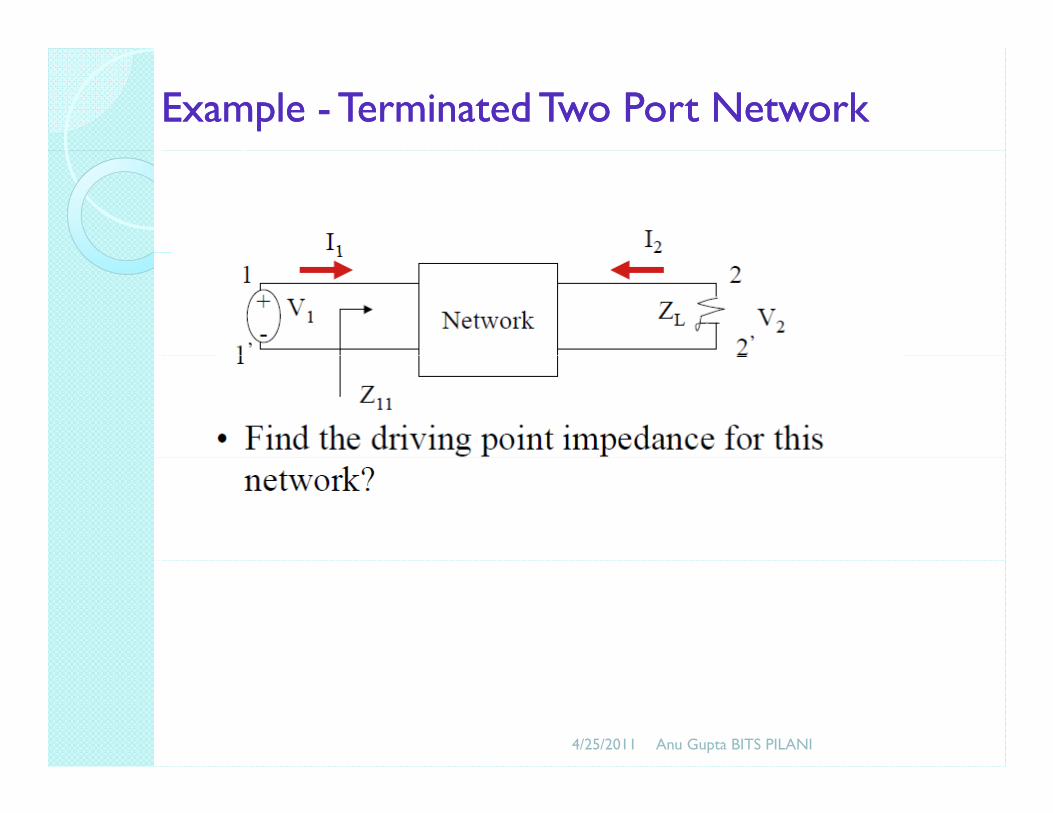
Example Example -- Terminated Two Port NetworkTerminated Two Port Network
4/25/2011 Anu Gupta BITS PILANI

Equations Equations Equations Equations
4/25/2011 Anu Gupta BITS PILANI

Driving point impedanceDriving point impedanceDriving point impedanceDriving point impedance
4/25/2011 Anu Gupta BITS PILANI

EXAMPLEEXAMPLE——DO YOURSELFDO YOURSELF
4/25/2011 Anu Gupta BITS PILANI

System Analysis Using Z ParametersSystem Analysis Using Z Parameters
For Analysis, it is customary to connect a For Analysis, it is customary to connect a signal source with a series impedance to the input port and a load impedance to the output input port and a load impedance to the output port.
4/25/2011 Anu Gupta BITS PILANI

4/25/2011 Anu Gupta BITS PILANI

Hybrid parametersHybrid parameters
4/25/2011 Anu Gupta BITS PILANI

4/25/2011 Anu Gupta BITS PILANI

Example1 Example1
4/25/2011 Anu Gupta BITS PILANI

4/25/2011 Anu Gupta BITS PILANI

Relationship of h and z parametersRelationship of h and z parameters
4/25/2011 Anu Gupta BITS PILANI

ShortShort--circuit Admittance Parameters of a circuit Admittance Parameters of a TTTwoTwo--portport
4/25/2011 Anu Gupta BITS PILANI

4/25/2011 Anu Gupta BITS PILANI

4/25/2011 Anu Gupta BITS PILANI

Y parameter modelY parameter model
4/25/2011 Anu Gupta BITS PILANI

Transmission parametersTransmission parametersTransmission parametersTransmission parameters
4/25/2011 Anu Gupta BITS PILANI

4/25/2011 Anu Gupta BITS PILANI

Cascaded two port Cascaded two port nwnwpp
4/25/2011 Anu Gupta BITS PILANI


![Two-Port Networks [相容模式] - National Chiao Tung University · 2013-01-08 · •One-Port Networks –Two-terminal circuits –Resistors, capacitors, inductors •Two-Port Networks](https://static.documents.pub/doc/80x56/5f7e545495701c2bc316fb60/two-port-networks-c-national-chiao-tung-2013-01-08-aone-port.jpg)