Getting Started with Computing 1 Product Overview 2 Setting Up Computing Software 3 Using Computing to Access Data 4 Accessing the Process Data with the Data Control 5 User Controls 6 S7 Diagnostics Buffer Control (DBuffer) 7 Designing Simple Process Forms with the WinAC SoftContainer 8 Creating Tag Files with the TagFile Configurator 9 Memory Areas of the S7 Controllers A Properties and Methods B Events C Using the Computing Configuration Tool D Using Computing with DCOM E Guidelines for Programming with Computing F Using Control Engine Strings G Edition: 4 C79000–G7076–C218–04 Computing User Manual SIMATIC
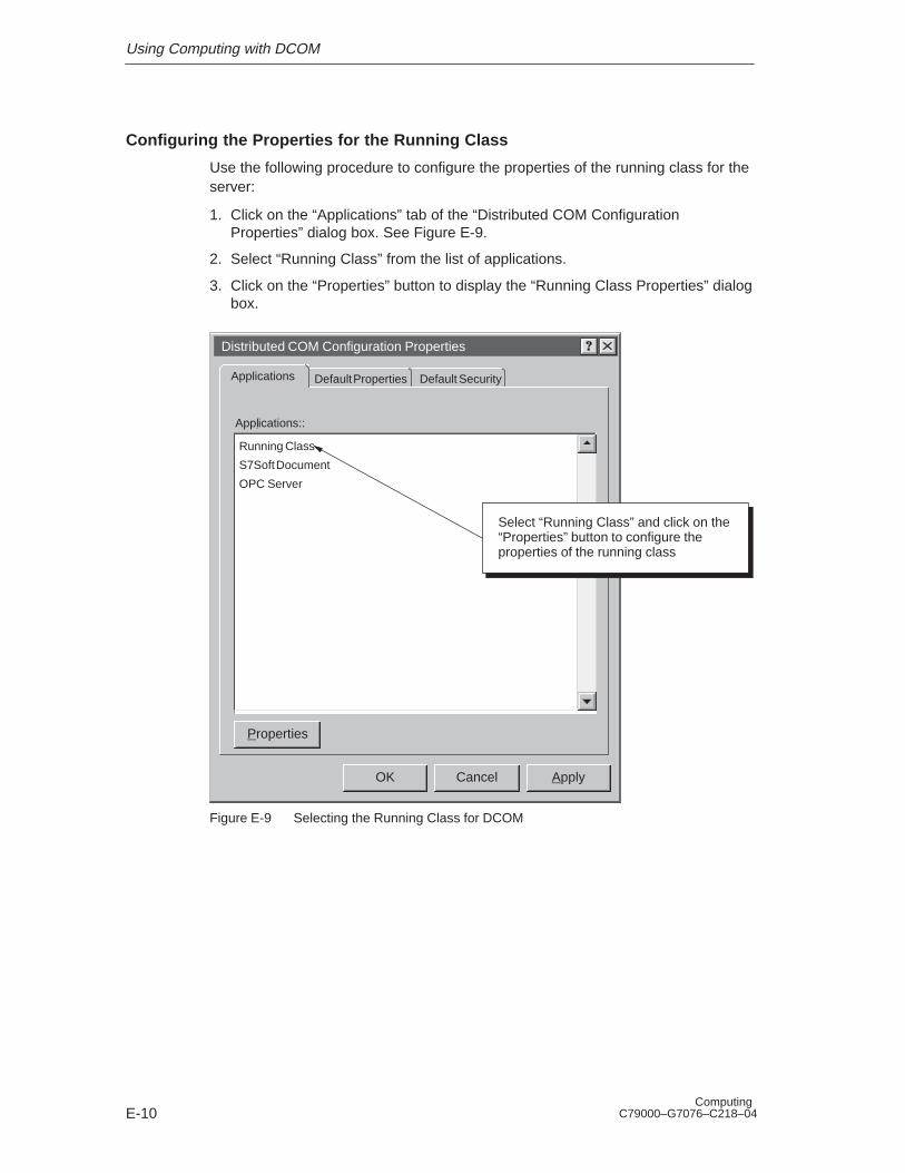
Transcript
Getting Started with Computing 1
Product Overview 2
Setting Up Computing Software 3
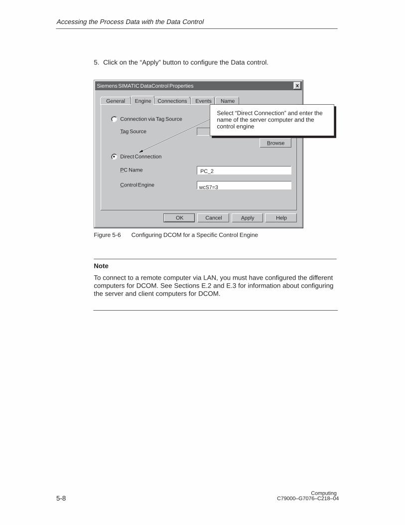
Using Computing to Access Data 4
Accessing the Process Data with theData Control
5
User Controls 6
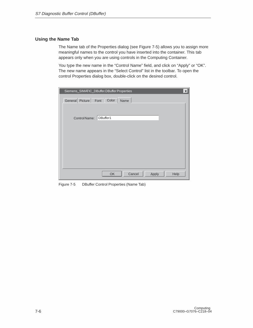
S7 Diagnostics Buffer Control (DBuffer) 7
Designing Simple Process Forms withthe WinAC SoftContainer
8
Creating Tag Files with the TagFileConfigurator
9
Memory Areas of the S7 Controllers A
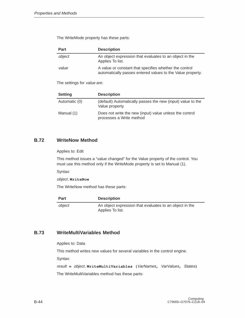
Properties and Methods B
Events C
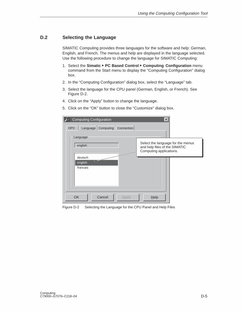
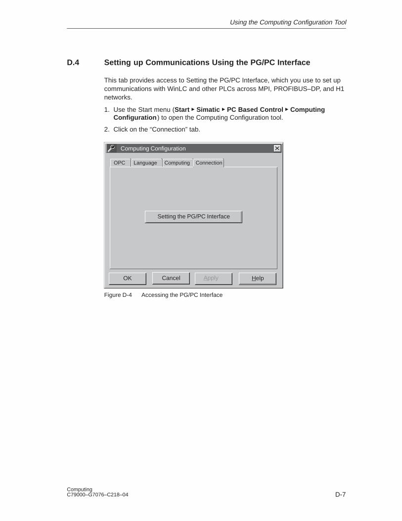
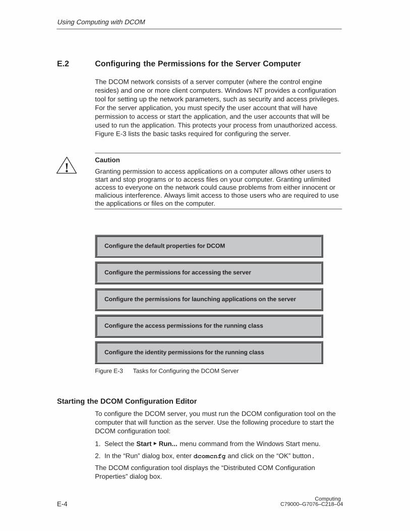
Using the Computing Configuration Tool D
Using Computing with DCOM E
Guidelines for Programming withComputing
F
Using Control Engine Strings G
Edition: 4
C79000–G7076–C218–04
Computing
User Manual
SIMATIC
Index-2Computing
C79000–G7076–C218–04
!Danger
indicates that death, severe personal injury or substantial property damage will result if proper precau-tions are not taken.
!Warning
indicates that death, severe personal injury or substantial property damage can result if proper precau-tions are not taken.
!Caution
indicates that minor personal injury or property damage can result if proper precautions are not taken.
Note
draws your attention to particularly important information on the product, handling the product, or to aparticular part of the documentation.
Qualified PersonnelOnly qualified personnel should be allowed to install and work on this equipment. Qualified persons aredefined as persons who are authorized to commission, to ground, and to tag circuits, equipment, and sys-tems in accordance with established safety practices and standards.
Correct UsageNote the following:
!Warning
This device and its components may only be used for the applications described in the catalog or thetechnical descriptions, and only in connection with devices or components from other manufacturerswhich have been approved or recommended by Siemens.
This product can only function correctly and safely if it is transported, stored, set up, and installed cor-rectly, and operated and maintained as recommended.
TrademarksSIMATIC�, SIMATIC HMI� and SIMATIC NET� are registered trademarks of SIEMENS AG.
Some of other designations used in these documents are also registered trademarks; the owner’s rightsmay be violated if they are used by third parties for their own purposes.
Safety GuidelinesThis manual contains notices which you should observe to ensure your own personal safety, as well as toprotect the product and connected equipment. These notices are highlighted in the manual by a warningtriangle and are marked as follows according to the level of danger:
We have checked the contents of this manual for agreement with the hardware andsoftware described. Since deviations cannot be precluded entirely, we cannot gua-rantee full agreement. However, the data in this manual are reviewed regularly andany necessary corrections included in subsequent editions. Suggestions for impro-vement are welcomed.
Disclaimer of LiabilityCopyright Siemens AG 1999 All rights reserved
The reproduction, transmission or use of this document or its contents is notpermitted without express written authority. Offenders will be liable for damages.All rights, including rights created by patent grant or registration of a utility modelor design, are reserved.
Siemens AGAutomation and Drives (A&D)Industrial Automation Systems (AS)Postfach 4848, D- 90327 Nürnberg
� Siemens AG 1999Technical data subject to change.
Siemens Aktiengesellschaft
iiiComputing C79000–G7076–C218–04
Preface
The Computing software uses the ActiveX (also known as OLE) technology ofMicrosoft to provide you with access to the data provided by your control engine.The Computing software consists of the following:
� A set of SIMATIC controls, which are ActiveX or OCX (OLE custom controls)controls for accessing control engines
� An OPC (OLE for process control) server that allows other OPC applications toaccess the data stored in the control engine (such as WinLC of WinAC Basis orthe CPU 416-2 DP ISA of WinAC Pro)
� TagFile Configurator for creating tag files that allow symbolic addressing andremote access to multiple control engines
� A configuration tool for configuring remote access
� An OLE container (SoftContainer) for creating process forms with the SIMATICcontrols
Note
As used by the Computing software, the term “control engine” applies to aprocessor or program that manages and manipulates data which is used to controla process or machine. The control engine can be can be either software orhardware.
WinAC Basis provides a Windows Logic Controller (WinLC) as its control engine,and WinAC Pro provides a slot PLC as its control engine. (The term “slot PLC” inthe manual refers to a slot PLC such as CPU 416–2 DP ISA or CPU 416–2 DPISA Lite. In the manual, the CPU416–2 DP ISA Lite is treated identically to theCPU416–2 DP ISA.) The ActiveX controls provided by Computing communicatewith these control engines, as well as other SIMATIC S7 controllers.
Audience
This manual is intended for engineers, programmers, and maintenance personnelwho have a general knowledge of programmable logic controllers (PLCs).
Scope of the Manual
This manual describes the features and the operation of version 3.0 of theComputing software.
Preface
ivComputing
C79000–G7076–C218–04
How to Use This Manual
This manual provides information focused for different audiences. Not only arethere two methods for accessing the process data (either using the ActiveXcontrols or the OPC interface), but there are also different levels of complexity foreach method. You can either use the control provided, or you can write programsthat include the controls.
If you will be using the ActiveX (OCX) controls in a container application such asVisual Basic, refer to Getting Started (Chapter 1) and Product Overview(Chapter 2).
The chapters for the specific SIMATIC controls provide information aboutConfiguring the controls. Appendix B describes the properties and methods for thecontrols, and Appendix C describes the events.
If you will be using the OPC interface:
� If you will be connecting an existing (third-party) OPC client application to theWinAC products, refer to the product overview (Chapter 2) for the name of theOPC server object.
� If you will be designing a client application for use with the WinAC products,refer to the OPC specification (OLE for Process Control Data Access Standard,version 2.0 from the OPC Foundation).
Other Manuals
You can find information in the online help for the Computing software. Foradditional information, refer to the following manuals:
Title Content
System Software forS7-300 and S7-400Program DesignProgramming Manual
This manual provides basic information about the structure of theoperating system and how to design a user program for WinLC.Use this manual when creating a user program with the STEP 7automation software.
OPC Server InterfaceManual
This manual describes the browsable OPC server interfaceprovided with the Computing software.
Windows LogicController (WinLC)User Manual
This manual provides basic information about the performancecharacteristics and operation of the WinLC controller.
This manual provides basic information about the performancecharacteristics and operation of the CPU 416–2 DP ISA controller.
Preface
vComputing C79000–G7076–C218–04
Additional Assistance
If you have any questions not answered in this or one of the other STEP 7manuals, if you need information on ordering additional documentation orequipment, or if you need information on training, please contact your Siemensdistributor or sales office.
To contact Customer Service for Siemens in North America:
E-1 Using SIMATIC Computing on a Single Computer E-2. . . . . . . . . . . . . . . . . . . E-2 Using Computing over DCOM E-3. . . . . . . . . . . . . . . . . . . . . . . . . . . . . . . . . . . . . E-3 Tasks for Configuring the DCOM Server E-4. . . . . . . . . . . . . . . . . . . . . . . . . . . . E-4 Distributed COM Configuration Properties E-5. . . . . . . . . . . . . . . . . . . . . . . . . . E-5 Configuring the Default Access Permissions for DCOM E-6. . . . . . . . . . . . . . . E-6 Changing the Access Permissions for Users or Groups E-7. . . . . . . . . . . . . . . E-7 Configuring the Default Launch Permissions for DCOM E-8. . . . . . . . . . . . . . . E-8 Changing the Launch Permissions for Users or Groups E-9. . . . . . . . . . . . . . . E-9 Selecting the Running Class for DCOM E-10. . . . . . . . . . . . . . . . . . . . . . . . . . . . E-10 Configuring the DCOM Access Permissions for the Server E-11. . . . . . . . . . . . E-11 Changing the Access Permissions for Users or Groups E-12. . . . . . . . . . . . . . . E-12 Configuring the DCOM Identity Permissions for the Server E-13. . . . . . . . . . . . E-13 Tasks for Configuring the DCOM Client E-14. . . . . . . . . . . . . . . . . . . . . . . . . . . . . E-14 Distributed COM Configuration Properties E-15. . . . . . . . . . . . . . . . . . . . . . . . . . E-15 Configuring the Default Access Permissions for DCOM E-16. . . . . . . . . . . . . . . E-16 Changing the Access Permissions for Users or Groups E-17. . . . . . . . . . . . . . . E-17 Configuring the Default Launch Permissions for DCOM E-18. . . . . . . . . . . . . . . E-18 Changing the Launch Permissions for Users or Groups E-19. . . . . . . . . . . . . . . F-1 Connecting to the Control Engine (Scrollbar Control Example) F-9. . . . . . . . .
Contents
xviComputing
C79000–G7076–C218–04
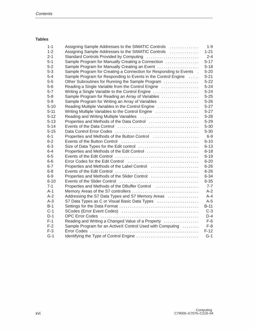
Tables
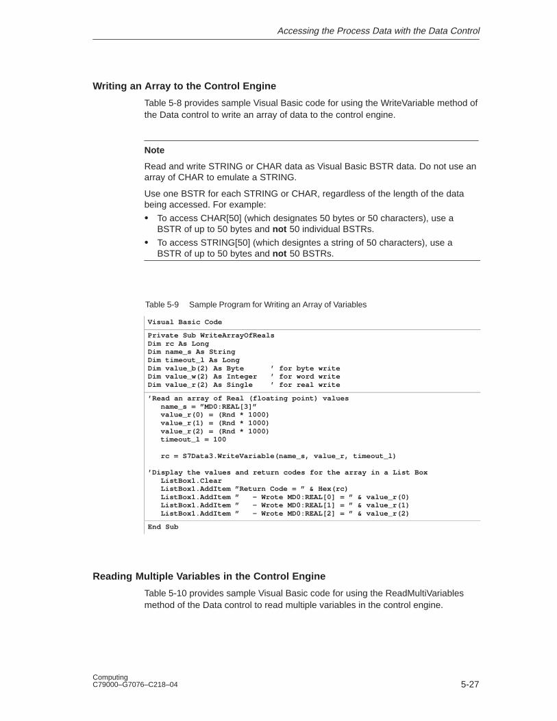
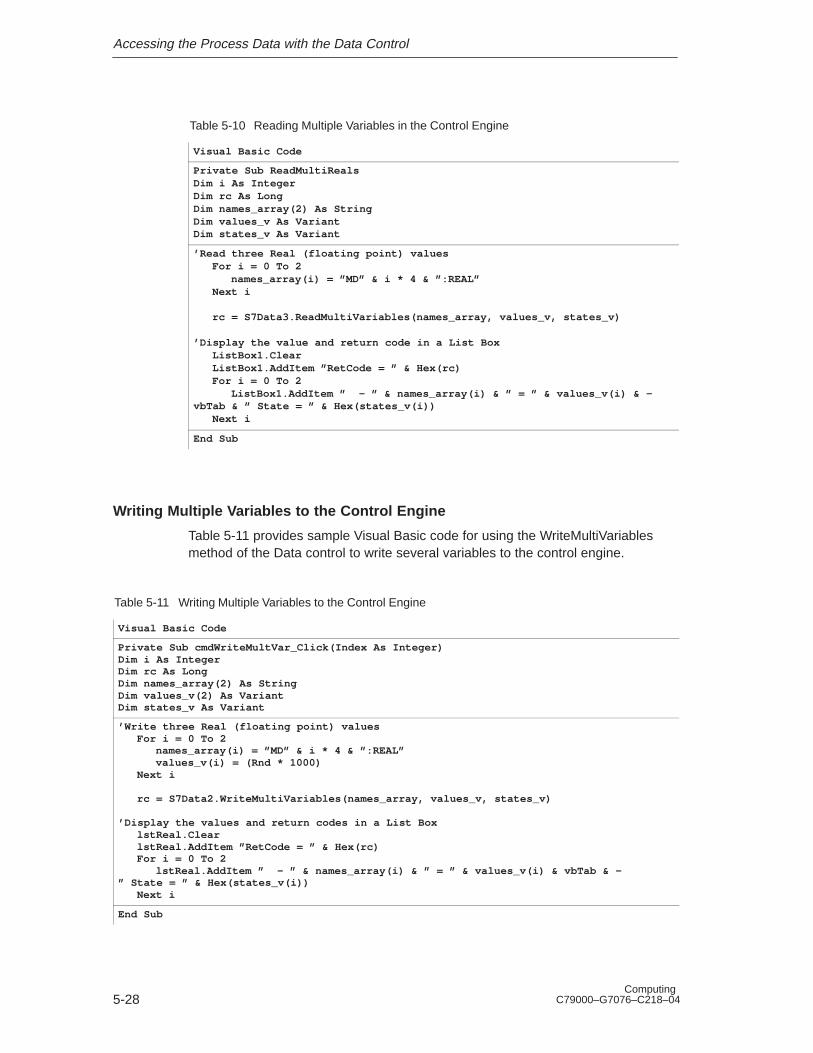
1-1 Assigning Sample Addresses to the SIMATIC Controls 1-9. . . . . . . . . . . . . . 1-2 Assigning Sample Addresses to the SIMATIC Controls 1-21. . . . . . . . . . . . . . 2-1 Standard Controls Provided by Computing 2-4. . . . . . . . . . . . . . . . . . . . . . . . . 5-1 Sample Program for Manually Creating a Connection 5-17. . . . . . . . . . . . . . . . 5-2 Sample Program for Manually Creating an Event 5-18. . . . . . . . . . . . . . . . . . . . 5-3 Sample Program for Creating a Connection for Responding to Events 5-20. 5-4 Sample Program for Responding to Events in the Control Engine 5-21. . . . . 5-5 Other Subroutines for Running the Sample Program 5-22. . . . . . . . . . . . . . . . . 5-6 Reading a Single Variable from the Control Engine 5-24. . . . . . . . . . . . . . . . . . 5-7 Writing a Single Variable to the Control Engine 5-24. . . . . . . . . . . . . . . . . . . . . . 5-8 Sample Program for Reading an Array of Variables 5-25. . . . . . . . . . . . . . . . . . 5-9 Sample Program for Writing an Array of Variables 5-26. . . . . . . . . . . . . . . . . . . 5-10 Reading Multiple Variables in the Control Engine 5-27. . . . . . . . . . . . . . . . . . . . 5-11 Writing Multiple Variables to the Control Engine 5-27. . . . . . . . . . . . . . . . . . . . . 5-12 Reading and Writing Multiple Variables 5-28. . . . . . . . . . . . . . . . . . . . . . . . . . . . 5-13 Properties and Methods of the Data Control 5-29. . . . . . . . . . . . . . . . . . . . . . . . 5-14 Events of the Data Control 5-30. . . . . . . . . . . . . . . . . . . . . . . . . . . . . . . . . . . . . . . 5-15 Data Control Error Codes 5-30. . . . . . . . . . . . . . . . . . . . . . . . . . . . . . . . . . . . . . . . 6-1 Properties and Methods of the Button Control 6-9. . . . . . . . . . . . . . . . . . . . . . 6-2 Events of the Button Control 6-10. . . . . . . . . . . . . . . . . . . . . . . . . . . . . . . . . . . . . 6-3 Size of Data Types for the Edit control 6-13. . . . . . . . . . . . . . . . . . . . . . . . . . . . . 6-4 Properties and Methods of the Edit Control 6-18. . . . . . . . . . . . . . . . . . . . . . . . . 6-5 Events of the Edit Control 6-19. . . . . . . . . . . . . . . . . . . . . . . . . . . . . . . . . . . . . . . . 6-6 Error Codes for the Edit Control 6-20. . . . . . . . . . . . . . . . . . . . . . . . . . . . . . . . . . 6-7 Properties and Methods of the Label Control 6-26. . . . . . . . . . . . . . . . . . . . . . . 6-8 Events of the Edit Control 6-26. . . . . . . . . . . . . . . . . . . . . . . . . . . . . . . . . . . . . . . . 6-9 Properties and Methods of the Slider Control 6-34. . . . . . . . . . . . . . . . . . . . . . . 6-10 Events of the Slider Control 6-35. . . . . . . . . . . . . . . . . . . . . . . . . . . . . . . . . . . . . . 7-1 Properties and Methods of the DBuffer Control 7-7. . . . . . . . . . . . . . . . . . . . . A-1 Memory Areas of the S7 controllers A-2. . . . . . . . . . . . . . . . . . . . . . . . . . . . . . . . A-2 Addressing the S7 Data Types and S7 Memory Areas A-4. . . . . . . . . . . . . . . A-3 S7 Data Types as C or Visual Basic Data Types A-5. . . . . . . . . . . . . . . . . . . . B-1 Settings for the Data Format B-11. . . . . . . . . . . . . . . . . . . . . . . . . . . . . . . . . . . . . . C-1 SCodes (Error Event Codes) C-3. . . . . . . . . . . . . . . . . . . . . . . . . . . . . . . . . . . . . D-1 OPC Error Codes D-4. . . . . . . . . . . . . . . . . . . . . . . . . . . . . . . . . . . . . . . . . . . . . . . F-1 Reading and Writing a Changed Value of a Property F-6. . . . . . . . . . . . . . . . . F-2 Sample Program for an ActiveX Control Used with Computing F-8. . . . . . . . F-3 Error Codes F-12. . . . . . . . . . . . . . . . . . . . . . . . . . . . . . . . . . . . . . . . . . . . . . . . . . . . G-1 Identifying the Type of Control Engine G-1. . . . . . . . . . . . . . . . . . . . . . . . . . . . . .
1-1Computing C79000–G7076–C218–04
Getting Started with Computing
Chapter Overview
The Computing software provides you with a variety of ways to access and to usedata from a control engineer, such as an S7 CPU, the Windows Logic Controller(WinLC) of WinAC Basis, or a slot PLC such as the CPU 416-2 DP ISA ofWinAC Pro.
This chapter provides some easy programming examples to help you becomefamiliar with the power and flexibility that can be achieved by using the ActiveXcontrols provided by SIMATIC Computing. You can find the sample programs inthe following directory on the drive where you installed the Computing software:
[C:]\Siemens\WinAC\Examples
!Warning
After you assign a variable to the Value property of a SIMATIC or a third-partyActiveX control, the control is able to access process data. When you change thevalue that is displayed in the control, you are changing the value in the actualprocess. Do not connect this example to a control engine that is connected toequipment.
Altering process data can cause unpredictable process operation, andunpredictable process operation could result in death or serious injury topersonnel, and/or damage to equipment.
Exercise caution to ensure that you do not access any data that could causeprocess equipment to operate erratically. Always install a physical emergency stopcircuit for your machine or process.
Section Description Page
1.1 Overview 1-2
1.2 Creating a Sample I/O Panel 1-4
1.3 Connecting Third-Party Controls to a Data Control 1-12
1.4 Using Computing with Microsoft Excel 1-15
1.5 Using the SoftContainer Provided by Computing 1-19
1
Getting Started with Computing
1-2Computing
C79000–G7076–C218–04
1.1 Overview
Computing allows you not only to access the data in the control engine, but alsoallows you flexibility in how you access the data and what you you can do with thedata.
The examples in this chapter show some of the ways you can use the ActiveXcontrols provided by Computing. As shown in Figure 1-1, this chapter providessamples of subroutines for the following applications:
� Create a user interface: You can use a the SIMATIC control with a third-partycontainer (such as Microsoft’s Visual Basic) to create an I/O interface panel.See Section 1.2. (You can use this panel to test the other sample programs inthis chapter.)
� Use a standard ActiveX control: You can also use a standard control (such as aLabel control from Visual Basic) to access data in the control engine. SeeSection 1.3.
� Load data from the control engine into standard software packages: You canload data into a Microsoft Office application (such as Microsoft’s Excel). SeeSection 1.4.
Instead of using the third-party container (Section 1.2), you can use theSoftContainer provided by Computing to create a simple I/O panel. SeeSection 1.5.
You can find the sample programs in the following directory on the drive where youinstalled the Computing software: [C:]\Siemens\WinAC\Examples
File CPU HelpWinLC
PS
CPU
ONBATTF
INTFEXTFBUSF1BUSF2FRCERUNSTOP
RUNRUN-P
MRES
STOP
Control engine
I/O Panel
I 0.0
OFF
I 0.1
OFF
I 0.2
OFF
0 0 0
QB0 QB1 QB2
Standard ActiveX Control
Excel
Label control
Interface Panel
Third-party application
Figure 1-1 Using Computing to Access Data in the Control Engine
Getting Started with Computing
1-3Computing C79000–G7076–C218–04
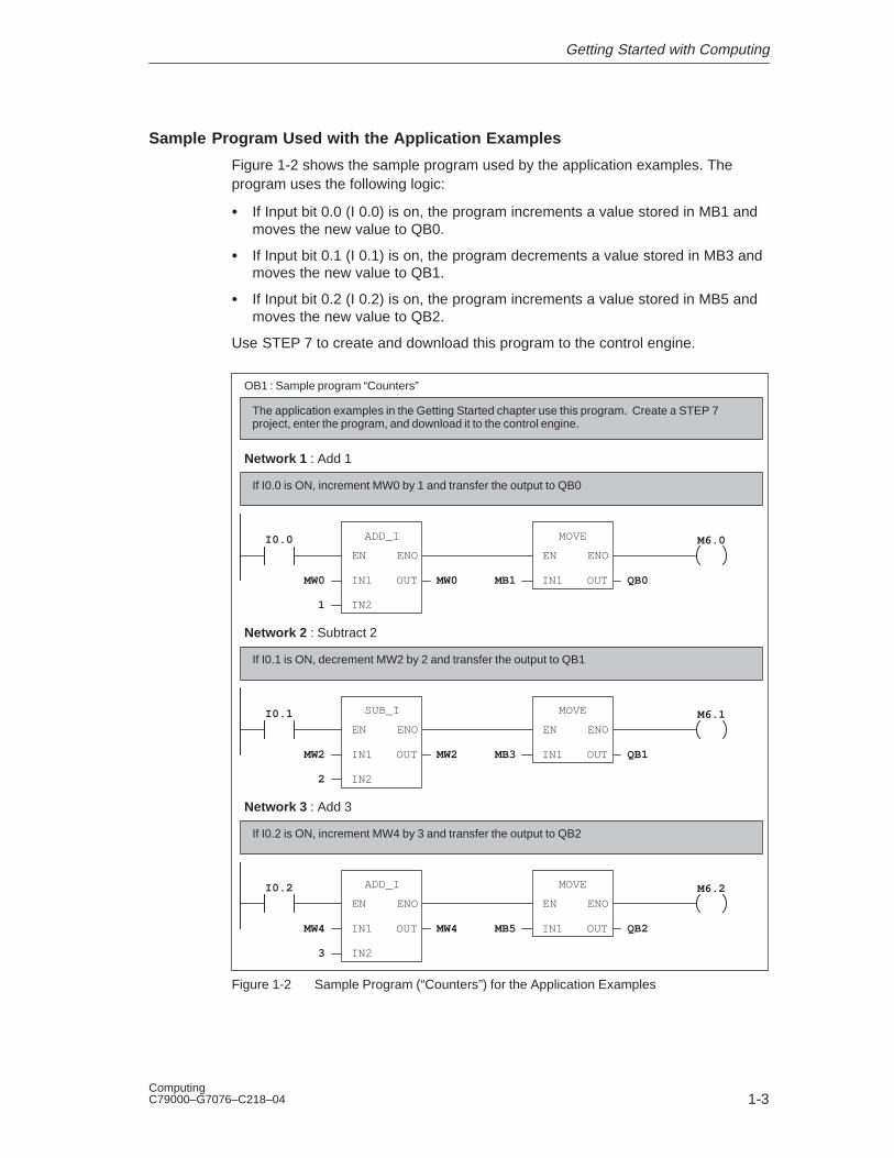
Sample Program Used with the Application Examples
Figure 1-2 shows the sample program used by the application examples. Theprogram uses the following logic:
� If Input bit 0.0 (I 0.0) is on, the program increments a value stored in MB1 andmoves the new value to QB0.
� If Input bit 0.1 (I 0.1) is on, the program decrements a value stored in MB3 andmoves the new value to QB1.
� If Input bit 0.2 (I 0.2) is on, the program increments a value stored in MB5 andmoves the new value to QB2.
Use STEP 7 to create and download this program to the control engine.
OB1 : Sample program “Counters”
M6.0I0.0
EN
IN1MW0
Network 1 : Add 1
MW0
ENO
OUT
IN21
ADD_I
EN
IN1MB1 QB0
ENO
OUT
MOVE
If I0.0 is ON, increment MW0 by 1 and transfer the output to QB0
The application examples in the Getting Started chapter use this program. Create a STEP 7project, enter the program, and download it to the control engine.
M6.1I0.1
EN
IN1MW2
Network 2 : Subtract 2
MW2
ENO
OUT
IN22
SUB_I
EN
IN1MB3 QB1
ENO
OUT
MOVE
If I0.1 is ON, decrement MW2 by 2 and transfer the output to QB1
M6.2I0.2
EN
IN1MW4
Network 3 : Add 3
MW4
ENO
OUT
IN23
ADD_I
EN
IN1MB5 QB2
ENO
OUT
MOVE
If I0.2 is ON, increment MW4 by 3 and transfer the output to QB2
Figure 1-2 Sample Program (“Counters”) for the Application Examples
Getting Started with Computing
1-4Computing
C79000–G7076–C218–04
1.2 Creating a Sample I/O Panel
The Data control allows any ActiveX container (such as Visual Basic 5.0) to accessdata in the control engine. You can use the SIMATIC controls provided byComputing with Visual Basic to create a simple I/O panel that interacts with aprogram running on a control engine
To create this sample application, you need the following items:
� Microsoft Visual Basic 5 or higher
� SIMATIC controls from Computing
� Control engine: for example, WinLC or a slot PLC such as CPU 416-2 DP ISA
� Sample program (see Section 1.1)
� STEP 7 (to download the program to the control engine)
!Caution
Using the timer function improperly or using breakpoints in Visual Basic withComputing can cause problems that could potentially cause your computer orapplication to crash or lock up. Depending on the configuration, this could causethe application to lose communication with the control engine. This could causeunpredictable process operation, which could result in death or serious injury topersonnel, and/or damage to equipment.
Always install a physical emergency stop circuit for your machine or process.
Concerning VB timers: The Timer function in Visual Basic version 5 allows atimer to interrupt code in progress within the same thread, which can causeproblems with potentially serious consequences. If you use VB timers withComputing, observe the following guidelines:
� Always kill (disable) the timers in the Form_Unload subroutine. Otherwise, atimer can trigger an event while the VB program is shutting down; this conditioncould cause your computer or your application to crash, lock up, or to continuerunning invisibly.
� If you start your timer in the Form_Load subroutine, the timer event could occurbefore the other objects have been instantiated. In order to ensure that theobjects have been properly instantiated, always start a timer in the Form_Loadsubroutine with a large interval (such as 1 or 2 seconds) to allow the objects tobe properly instantiated. Subsequent timer intervals can be set to shorterintervals.
Getting Started with Computing
1-5Computing C79000–G7076–C218–04
Inserting the SIMATIC Controls into the Toolbox for Visual Basic
Use the following procedure to create the sample I/O panel:
1. Open a standard Visual Basic project:
– Select the File � New Project menu command to display the “New Project”dialog box.
– Select the “Standard EXE” icon and click on the “Open” button.
2. Select the Project � Components menu command to display the“Components” dialog box.
3. As shown in Figure 1-3, select the following SIMATIC controls in the“Components” dialog box:
– Data control (Siemens SIMATIC Data Control)
– Panel control (Siemens S7 Panel Control, which comes with WinLC or a slotPLC)
– User controls (Siemens SIMATIC UserControls) The icons for Button, Label,Slider, and Edit appear in the Icon tab.
4. Click on the “Apply” button. The SIMATIC controls that you selected appear inthe toolbox for Visual Basic. Click on the “OK” button to close the “Components”dialog box.
Components
Insertable ObjectsControls
OK Cancel Apply
Designers
Browse...
Selected Items Only
� Click on the Data control and theUser controls.
� Click on the “Apply” button to addthe control to the VB toolbox.
� Click on the “OK” button to close the“Components” dialog box.
Siemens SIMATIC Data ControlLocation: C:\SIEMENS\Common\OCX\S7WCDATX.OCX
Third-Party Control...Third-Party Control...
Siemens SIMATIC Data ControlSiemens SIMATIC Diagnostic Buffer CoSiemens SIMATIC User Controls
Figure 1-3 Adding SIMATIC Controls to the VB Toolbox
Getting Started with Computing
1-6Computing
C79000–G7076–C218–04
Creating the VB Form for the Sample I/O Panel
1. Insert one Data control, three Edit controls and three Button controls onto theVisual Basic form. See Figure 1-4.
2. Create standard VB label controls to indicate the address that you haveassigned for each of the controls. See Figure 1-4.
I/O Panel
I 0.0 I 0.1 I 0.2
0 0 0
QB0 QB1 QB2
Data control
VB Label controls
Edit controls
VB Label controls
OFF OFF OFFButton controls
Figure 1-4 Sample I/O Panel Created in Visual Basic
Assigning Variables in the Control Engine to the SIMATIC Controls
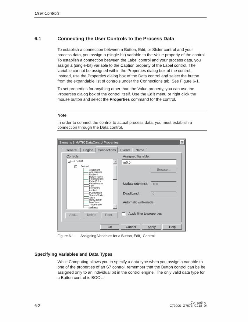
In order to connect the SIMATIC or third-party controls to the process data in thecontrol engine, you must assign a variable (memory location in the control engine)to the Value property (or to other properties) for each control. You use theConnection tab of “Properties” dialog box for the Data control to assign variables inthe control engine. You cannot assign a variable to the Value property of a controlby using the property list of the control itself.
Use the following procedure to assign variables to the SIMATIC controls:
1. Select the Data control and click the right mouse button to bring up the pop-upmenu. From the pop-up menu, select the Properties menu command todisplay the “Properties” dialog box for the Data control.
2. Select the “Connections” tab. Click on the “+” symbol to expand the list ofcontrols.
3. As shown in Figure 1-5, select the control and click on its “+” symbol to expandits properties list.
Getting Started with Computing
1-7Computing C79000–G7076–C218–04
Siemens SIMATIC DataControl Properties
Connections EventsGeneral
Assigned Variable:
Browse...
100
0
Update rate (ms):
Dead ban
Automati
Controls:
Add... Filter...
Button1
OK Cancel Apply Help
Engine
ApplyDelete
Name
Enabled
FalseCaptionFalseColorFalsePicture
TrueCaptionTrueColor
ValueTruePicture
AlignmentAppearance
Border Style
FontForeColor
PushButtonLocked
StretchModeStyle
Figure 1-5 Displaying the Expanded List of Properties
4. As shown in Figure 1-6, click on the “Filter” button.
Siemens SIMATIC DataControl Properties
Connections EventsGeneral
Assigned Variable:
100
0
Update rate (ms):
Dead band:
Automatic write mode:
Controls:
Add... Filter...
S7Data1
S7Soft1
Button1
OK Cancel Apply Help
Engine
Apply filter to propertiesDelete
Click on the “Filter” button to selectthe properties to be displayed
Name
Enabled
FalseCaptionFalseColorFalsePicture
AlignmentAppearance
Border Style
FontForeColor
PushButtonLocked
Figure 1-6 Using the Filter Button
5. As shown in Figure 1-7, enter the properties to display and click on the “Add”button. Use the “Edit” button to correct entries and the “Delete” button toremove entries.
Getting Started with Computing
1-8Computing
C79000–G7076–C218–04
Siemens SIMATIC DataControl Properties
Connections EventsGeneral
100
0
Controls:
Add...
S7Data1
S7Soft1
Button1
OK Cancel Apply Help
Engine
properties
Name
mode:
Property Filter
Visible Properties:
Add... Delete
Enabled
OK Cancel
Edit
Value
Click on the “Add” button to enter aproperty to the filter
Ena
FalFalFal
AligApp
Bor
FontFor
PuLoc
Figure 1-7 Adding Properties to the Filter
6. As shown in Figure 1-8, select the “Apply filter to properties” check box todisplay only the properties listed in the filter. You can use the “Apply filter toproperties” check box to toggle the filter on and off.
Siemens SIMATIC DataControl Properties
Connections EventsGeneral
Assigned Variable:
Browse...
Update rate (m
Dead band:
Automatic write mode:
Controls:
Add... Filter...
S7Data1
S7Soft1
Button2
Edit1
Button1
OK Cancel Apply Help
Engine
Apply filter to propertiesDelete
Enabled
Value
Edit1
Name
Click on the check box to togglethe property filter on and off
Figure 1-8 Applying the Filter to the Property List
Getting Started with Computing
1-9Computing C79000–G7076–C218–04
7. As shown in See Figure 1-9, select the Value property of the control.
Siemens SIMATIC DataControl Properties
Connections EventsGeneral
Assigned Variable:
i0.0
Browse...
100
0
Update rate (ms):
Dead ban
Automati
Controls:
Add... Filter...
OK Cancel Apply Help
Engine
ApplyDelete
N
S7Data1
S7Soft1
Button2
Edit1
Button1
Enabled
Edit1
Value
After you select the Value property,enter the memory location of the variable to be assigned to that property
Select the Value property.
Figure 1-9 Assigning a Variable in the Control Engine to a Property in a Control
8. Refer to Table 1-1 and assign the variables (memory addresses in the controlengine) to the SIMATIC controls.
9. Click on the “Apply” button to enter the assigned variables.
Table 1-1 Assigning Sample Addresses to the SIMATIC Controls
Control Address Description
Edit1 QB0 Output value of first counter
Edit2 QB1 Output value of second counter
Edit3 QB2 Output value of third counter
Button1 I 0.0 Enable bit for first counter
Button2 I 0.1 Enable bit for second counter
Button3 I 0.2 Enable bit for third counter
Getting Started with Computing
1-10Computing
C79000–G7076–C218–04
Selecting a Control Engine
Use the following procedure to configure the Data control for communicating withthe control engine:
1. Select the “Engine” tab to configure the control engine. See Figure 1-10.
2. Select the “Direct Connect” option and enter either the control engine, forexample, WinLC or wcS7=3 (for a slot PLC such as the CPU 416-2 DP ISA).Click on the “Apply” button to enter the data, and then click on the “OK” buttonto close the dialog box.
Note
wcS7=3 is identical to S7DosIntf/MPI=3, which is still enabled for compatibility.
Siemens SIMATIC DataControl Properties
Connections EventsGeneral
Tag Source
Connect via Tag Source
OK Cancel Apply Help
Engine
Direct Connect
PC Name
Control Engine wcS7=3
Browse
Enter WinLC or wcS7=3 as the typeof control engine
Name Select the option for a directconnection
Figure 1-10 Connecting the Data Control to a Control Engine
Getting Started with Computing
1-11Computing C79000–G7076–C218–04
Operating of the I/O Panel Program
Before you run the I/O Panel program, make certain that the control engine isrunning the sample program “Counters”.
Note
If the control engine (for example, WinLC or a slot PLC such as theCPU 416-2 DP ISA) is not active, the Data control cannot make a connection.Before setting Visual Basic into Run Mode, ensure that the control engine isrunning.
1. Select the File � Save Project menu command to save the program beforeswitching Visual Basic from Design mode to Run mode.
2. Click on the “Start” icon or select the Run � Start menu command to switchVisual Basic from Design mode to Run mode to run the I/O panel program.
3. Click on the Button Control for I 0.0 to start the first counter. See Figure 1-11.
– The Button control changes color to show the state of I 0.0.
– The Edit Control for QB0 displays the counter value.
4. Click on the Button control for I 0.1 to start the second counter. SeeFigure 1-11.
– The Button control changes color to show the state of PI 0.1.
– The Edit control for QB1 displays the counter value.
5. Click on the Button control for I 0.2 to start the third counter. See Figure 1-11.
– The Button control changes color to show the state of I 0.2.
– The Edit control for QB2 displays the counter value.
I/O Panel
I 0.0 I 0.1 I 0.2
0 0 0
QB0 QB1 QB2
OFF OFF OFF
Click here to startthe first counter
Click here to startthe second counter
Click here to startthe third counter
Figure 1-11 Operating the Sample I/O Panel
Getting Started with Computing
1-12Computing
C79000–G7076–C218–04
1.3 Connecting Third-Party Controls to a Data Control
You can use the Data control to connect any ActiveX control (such as a VB Labelcontrol) to data in the control engine. To create this sample application, you needthe following items:
� Microsoft Visual Basic 5 or higher
� Data control from Computing
� Control engine: for example, WinLC or a slot PLC such as CPU 416-2 DP ISA
� Sample program (see Section 1.1)
� STEP 7 (to download the program to the control engine and to turn on theperipheral input bits of the sample program)
You can also use the sample I/O Panel application to turn on the peripheralinput bits of the sample program running in the control engine. See Section 1.2for information about the I/O Panel application.
Creating a VB label that Displays a Value in the Control Engine
Use the following procedure to connect a Data control with a Label control:
1. Open a standard Visual Basic project: Use the File � New Project menucommand to display the “New Project” dialog box, then select the “StandardEXE” icon and click on the “Open” button.
2. Add the Data control to the VB toolbox. For information about adding controls tothe VB toolbox, see Section 1.1 and Figure 1-12.
Components
Insertable ObjectsControls
OK Cancel Apply
Designers
Browse...
Selected Items Only
Siemens SIMATIC Data ControlLocation: C:\SIEMENS\Common\OCX\S7WCDATX.OCX
� Click on the “Apply” button to addthe control to the VB toolbox.
� Click on the “OK” button to close the“Components” dialog box.
Figure 1-12 Adding the Data Control to the Visual Basic Toolbox
Getting Started with Computing
1-13Computing C79000–G7076–C218–04
3. Insert a Data control onto the VB form. (For information about inserting controlsonto the VB form, see Section 1.1.)
4. Insert a VB label on your form. Change the Border Style property to “1–FixedSingle.”
5. Select the Data control and click the right mouse button to bring up the pop-upmenu. From the pop-up menu, select Properties to display the “Properties”dialog box for the Data control.
6. From the “Properties” dialog box, select the “Connections” tab. Click on the “+”symbol to expand the list of controls.
7. Select the Label1 control and click on its “+” symbol to expand its properties list.
8. Select the Caption property and enter QB0 in the “Assigned Variable” field. SeeFigure 1-13. Click on the “Apply” and “OK” buttons to enter the data and closethe “Properties” dialog box.
Siemens SIMATIC DataControl Properties
Connections EventsGeneral
Assigned Variable:
qb0
Browse...
100
0
Update rate (ms):
Dead ban
Automati
Controls:
Add... Filter...
Label1
OK Cancel Apply Help
Engine
ApplyDelete
AlignmentAppearanceBackColorBorderStyle
ForeColorSelect the Caption property and enterthe QB0 in the “Assigned Variable”field.
Name
Caption
FontEnabled
Figure 1-13 Assigning a Variable to the Caption Property of a VB Label Control
Getting Started with Computing
1-14Computing
C79000–G7076–C218–04
Running the Sample Program for the Label Control
Save the program before switching Visual Basic from Design mode to Run mode.When the sample program runs, the caption of the label displays the value of QB0in the control engine.
Note
If the control engine (for example, WinLC or a slot PLC such as theCPU 416-2 DP ISA) is not active, the Data control cannot make a connection.Before setting Visual Basic into Run Mode, ensure that the control engine isrunning.
Use the following procedure to configure the Data control for communicating withthe control engine and for running the sample program.
1. Select the “Engine” tab to configure the control engine. See Figure 1-14.
2. Select the “Direct Connect” option and enter either WinLC or wcS7=3 (for a slotPLC such as the CPU 416-2 DP ISA) for the control engine. Click on the“Apply” button to enter the data, and then click on the “OK” button to close thedialog box.
3. Switch Visual Basic from Design mode to Run mode to run the sampleprogram.
Siemens SIMATIC DataControl Properties
Connections EventsGeneral
Tag Source
Connect via Tag Source
OK Cancel Apply Help
Engine
Direct Connect
PC Name
Control Engine wcS7=3
Browse
Enter WinLC or wcS7=3 as thetype of control engine
Name Select the option for a directconnection
Figure 1-14 Connecting to the Control Engine (Label Control Example)
Getting Started with Computing
1-15Computing C79000–G7076–C218–04
1.4 Using Computing with Microsoft Excel
Using the Data control in an Excel spreadsheet allows you to access the values inthe control engine. To create this sample application, you need the following items:
� Microsoft Excel 97 or Excel 2000
� Control engine: either WinLC, an S7 CPU in Excel, or a slot PLC such asCPU 416-2 DP ISA
� Sample program (see Section 1.1)
� STEP 7 (to download the program to the control engine and to turn on theperipheral input bits of the sample program)
This example shows how to use events to call code to update your Excel cells.Events are a means of tying changing data to code within a VBA form.
Note
You can also use the I/O Panel application to turn on the peripheral input bits ofthe sample program running in the control engine. See Section 1.2 for informationabout the I/O Panel application.
Creating a Command Button in Excel
The first step in creating the sample Excel application is to create a commandbutton. Use the following procedure to create a command button:
1. Start the Excel application. (If prompted about whether to enable or disablemacros, select the “Enable Macros” option.)
2. In the following cells of the spreadsheet, enter the following labels:
– In cell A1, enter: qb0
– In cell A2, enter: qb1
– In cell A3, enter: qb2
3. Select the View � Toolbars � Control Toolbox menu command to display theControl toolbox.
4. Click on the “Design Mode” icon in the Control toolbox to put the spreadsheetinto Design mode.
5. Insert a Command Button control onto the spreadsheet by clicking on the“Command Button” icon in the Control toolbox and then clicking the left mousebutton in an empty area of the spreadsheet.
6. Move or size the Command Button control as required.
Getting Started with Computing
1-16Computing
C79000–G7076–C218–04
Using the Visual Basic Editor to Configure the Command Button
After you have created the command button, you use the Visual Basic Editor inExcel to configure the command button for starting and stopping the program.
Use the following procedure to configure the command button:
1. Select the command button (CommandButton1).
2. Select the Tools � Macro � Visual Basic Editor menu command to display theVisual Basic editor.
3. In the Properties window, select the Caption property of CommandButton1 andenter the following caption:
Start Counting
4. Display the Code window by selecting the View � Code menu command. Select“CommandButton1” from the drop-down list for the Object field. Enter thefollowing code for the CommandButton1_Click() event:
UserForm1.show
5. Close the Code window for CommandButton1.
Creating a SIMATIC Data Control
1. Create a new user form by selecting the Insert � UserForm menu command.
2. In the “Toolbox” window, click the right mouse button to bring up a pop-up menuand select the Additional Controls... menu command. (To display the“Toolbox” window, select the View � Toolbox menu command.)
3. Scroll through the list of controls and select the Siemens Data control (byselecting the check box). Click on the “OK” button to insert the Data controlonto the toolbox.
4. Select the “Data control” icon in the “Toolbox” window and insert a Data controlonto UserForm1.
5. Select the Data control and click the right mouse button to bring up the pop-upmenu. From the pop-up menu, select the Properties menu command to displaythe properties for the Data control (S7Data1) in the Properties window.
6. In the Properties window for S7Data1, select the “(Custom)” property field andthen click on the expansion button to display the “Properties” dialog box for theData control.
Adding Events for the Data Control
1. In the “Properties” dialog box for the Data control, select the “Events” tab. In thelist under the “Keys” heading, select S7Data1.
2. Click on the “Add” button to add a new event key. See Figure 1-15. In the “Add”dialog box, enter QB0 in the “Add a new key” field.
After you click on the “OK” button, the event key is added to the S7Data1control.
Getting Started with Computing
1-17Computing C79000–G7076–C218–04
Siemens SIMATIC DataControl Properties
Connections EventsGeneral
Assigned VariaKeys:
S7Soft1
S7Data1
Add...
OK Cancel Apply Help
Engine Name
Add
Add a new key:
CancelOK
QB0
Select the Data control and clickon the “Add” button to display the“Add” dialog box.
Enter QB0 in the “Add new key”field and click on the “OK” button.
Figure 1-15 Adding an Event Key to the Data Control
3. In the “Properties” dialog box, enter memory address QB0 in the “AssignedVariable” field. See Figure 1-16.
4. Click on the “Apply” button to accept the assigned variable. Notice that theevent key “QB0” appears in boldface under S7Data1.
5. Enter new event keys for QB1 (memory address QB1) and QB2 (memoryaddress QB2) by selecting S7Data1 again and repeating steps 2. and 3.
Siemens SIMATIC DataControl Properties
Connections EventsGeneral
Assigned Variable:
QB0
Browse...
100
0
Update rate (ms):
Dead band:
Keys:
S7Soft1
S7Data1
Add... Delete
OK Cancel Apply Help
QB0
Engine Name
Select the event key (QB0).
Enter QB0 in the “AssignedVariable” field and click on the“Apply” button.
Figure 1-16 Assigning a Variable to an Event Key
Getting Started with Computing
1-18Computing
C79000–G7076–C218–04
Configuring the Control Engine for the Data Control
1. In the “Properties” dialog box for the Data control, select the “Engine” tab toconfigure the control engine.
2. Select the “Direct Connect” option and enter either WinLC, an S7 CPU inExcel, or wcS7=3 (for a slot PLC such as the CPU 416-2 DP ISA) as the controlengine. Click on the “Apply” button to enter the data, and then click on the “OK”button to close the dialog box.
Entering a Sample Program for the Data Control
1. Select the Data control in UserForm1.
2. Select the View � Code menu command to display the code window for theData control.
3. Select S7Data1 from the drop-down list of the Object field.
4. For the S7Data1_ValueChanged event, enter the following program:
5. Close the Code window for the Data control and close UserForm1.
Running the Sample Program
1. Select the File � Close and Return to Microsoft Excel menu command toreturn to the spreadsheet.
2. Exit Design mode by clicking on the “Exit Design Mode” icon in the “Toolbox”window.
3. Connect the Excel spreadsheet to the control engine by clicking on the “StartCounting” command button.
4. Use the sample I/O panel (see Section 1.2) to start and stop the sampleprogram in the control engine.
Note
To exit Excel or to activate the Excel menus, you must first close UserForm1.
Getting Started with Computing
1-19Computing C79000–G7076–C218–04
1.5 Using the SoftContainer Provided by Computing
Computing provides a simple OLE container application (SoftContainer) fordisplaying and modifying the data from the control engine. Using this container,you can quickly insert the SIMATIC controls into a process form. (A process formis the SoftContainer document, or file, with the various controls.) No code can bewritten with this tool.
In order to run this sample process form, you need to have downloaded the sampleprogram (see Section 1.1) to the control engine.
Inserting SIMATIC Controls into the Process Form
To start the Computing software, select the Simatic � PC Based Control �
Computing Softcontainer menu command from the Start menu. TheSoftContainer opens with the default process form (S7Soft1). You will insert theSIMATIC controls into this process form. See Figure 1-17.
1. In the toolbar, click on the icon for the Data control. (Moving the arrow pointerover an icon and then keeping it stationary for a second will display a tooltip foridentifying the icon.)
2. Move the arrow pointer to the open process form. Notice that once the cursormoves inside the process form, the arrow pointer changes to a cross-hairpointer.
3. Click the left mouse button to insert the Data control.
The arrow pointer changes toa cross-hair pointer within thecontainer.
Click the left mouse button toinsert the control.
Select the control from thetoolbar.
Figure 1-17 Inserting a SIMATIC Control into the SoftContainer
Getting Started with Computing
1-20Computing
C79000–G7076–C218–04
Repeat these steps to insert three Button controls and three Edit controls. (Formore information about inserting controls into the SoftContainer, see Section 8.2.)Figure 1-18 shows a sample layout for the controls in the process form (S7Soft1).
Figure 1-18 Using the SoftContainer to Create a Sample I/O Panel
Configuring the Properties for the SIMATIC Controls
You use the Properties dialog box of the Data control to connect the otherSIMATIC controls to the control engine.
To assign a variable (memory location in the control engine) to a SIMATIC control,select the Data control and click the right mouse button (“right-click”) to display theshortcut menu. From the shortcut menu, select the Properties menu command forthe Data control to display the Properties dialog box.
Configuring the the Control Engine for the Data Control
This example presumes that you have installed a control engine. For moreinformation about connecting to control engines, see Section 5.3.
Use the following procedure to connect the Data control to the control engine:
1. Select the “Engine” tab of the Properties dialog box for the Data control.
2. Select the “Direct Connect” option and enter either WinLC or wcS7=3 (for aslot PLC such as the CPU 416-2 DP ISA) as the control engine.
3. Click on the “Apply” button to enter this data.
Getting Started with Computing
1-21Computing C79000–G7076–C218–04
Siemens SIMATIC DataControl Properties
Connections EventsGeneral
Tag Source
Connect via Tag Source
OK Cancel Apply Help
Engine
Direct Connect
PC Name
Control Engine wcS7=3
Browse
Enter WinLC or wcS7=3 as thetype of control engine
Name Select the option for a directconnection
Figure 1-19 Connecting to the Control Engine (SoftContainer Example)
Assigning a Variable (Memory Location) to a Property
The Data control establishes a connection between the individual SIMATICcontrols and the control engine. In the Properties Dialog box for the Data control,you assign variables (memory locations in the control engine) to the individualproperties of the controls.
Refer to Table 1-2 and assign the variables (memory addresses in the controlengine) to the SIMATIC controls.
Table 1-2 Assigning Sample Addresses to the SIMATIC Controls
Control Address Description
Edit1 QB0 Output value of first counter
Edit2 QB1 Output value of second counter
Edit3 QB2 Output value of third counter
Button1 I 0.0 Enable bit for first counter
Button2 I 0.1 Enable bit for second counter
Button3 I 0.2 Enable bit for third counter
Getting Started with Computing
1-22Computing
C79000–G7076–C218–04
Use the following procedure to connect the Value property of Button controlButton1 to PI 0.0 in the control engine:
1. Select the “Connections’ tab of the “Properties’ dialog box for the Data control.
2. Click on the “+” beside SIMATIC Data1 (or double-click on SIMATIC Data1) todisplay the listing of the controls in the container.
3. Click on the “+” beside Button1 (or double-click on Button1) to display theproperties for the Button control. See Figure 1-20.
4. Scroll down to and select (click on) the Value property. Notice that when youselect the Value property, the “Assigned Variable” field becomes active.
5. As shown in Figure 1-20, enter “i0.0” in the “Assigned Variable” field. (You canuse either upper case or lower case for designating memory locations.)
6. Click on the “Apply” button to enter the data.
Repeat this procedure for the other Button controls and the three Edit controls,entering the variables listed in Table 1-2. After you have configured theconnections for all of the controls, click on the “OK” button to confirm the changesand close the “Properties“ dialog box.
Siemens SIMATIC DataControl Properties
Connections EventsGeneral
Assigned Variable:
i0.0
Browse...
100
0
Update rate (ms):
Dead ban
Automat
Controls:
Add... Filter...
Button1
OK Cancel Apply Help
Engine
ApplyDelete
After you select the property from thehierarchy, enter the memory locationof the variable to be assigned to thatproperty
Name
Enabled
FalseCaptionFalseColorFalsePicture
TrueCaptionTrueColor
ValueTruePicture
AlignmentAppearance
Border Style
FontForeColor
PushButtonLocked
StretchModeStyle
Figure 1-20 Assigning the Value Property to a Variable
Configuring the Edit Control for Binary Data
The Edit control is able to display data in a variety of formats. For this example,you will configure the Edit controls to display the byte of data (QB0, QB1, or QB2)in decimal format.
Getting Started with Computing
1-23Computing C79000–G7076–C218–04
Note
The “Data type” field of the Edit control determines the size of the data to bedisplayed.
Use the following procedure to configure the Edit control:
1. Select the Edit control (Edit1) and click the right mouse button (“right-click”) todisplay the shortcut menu. From the shortcut menu, select the Propertiesmenu command for the Edit control to display the “Properties” dialog box.
2. Click on the arrow beside the “Data Format” field to display the drop-downmenu.
3. Scroll to the entry for decimal and click on “2 – wDecimal” to display the valuein binary format (0 or 1). See Figure 1-21.
4. Click on the “Apply” button to enter the data and click on the “OK” button toclose the “Properties” dialog box.
Repeat this procedure for the other Edit controls (Edit2 and Edit3).
Siemens_SIMATIC_UserControls.Edit Properties
OK Cancel
General
Apply Help
Precision:
1 – wThreeD
Data Format:
Enabled
ColorScaling Font
2 – wDecimal Locked
Appearance:
1 – wFixedSingleBorderstyle:
WriteMode:
Alignment:
Name
Zer3
0 –wAutomatic
Select “Decimal” from the drop-down list box for “Data Format”
Figure 1-21 Configuring the Display Properties of the Edit control
Getting Started with Computing
1-24Computing
C79000–G7076–C218–04
Connecting the SIMATIC Controls to the Control Engine
If the control engine is not active, your controls have no process to monitor. Whenyou are ready to use the controls to view or modify data, the control engine mustbe running.
Use the following procedure to connect the controls in the container to the controlengine:
1. Click on the “Run” icon (or select the Mode � Run menu command) to switchthe container from Design mode to Run mode. See Figure 1-22.
2. Click on the Button controls to start (or stop) the counters in the sampleprogram. Notice that when the Button control changes state, the valuedisplayed in the corresponding Edit control changes.
3. Click on the “Design” icon (or select the Mode � Design menu command) toswitch the container from Run mode to Design mode (disconnecting thecontrols from the control engine).
Click on the Run button toswitch the container fromDesign mode to Run mode.
OFF OFF OFF
Click on the Button control to change bitI 0.0 from “0” to “1”
The Edit control shows changing countervalue in QB0
Figure 1-22 Placing the Container into Run Mode
2-1Computing C79000–G7076–C218–04
Product Overview
Chapter Overview
The Computing package provides a method for other software applications toaccess the process data of your application. The Computing software providesActiveX controls that can be inserted in any software application that is an ActiveXcontrol container, like Visual Basic or Visual C++.
While the SIMATIC controls provided by Computing have been tested with othercontainers provided by other vendors, some third-party containers may not functionas described in this document. Refer to Appendix F for guidelines about third-partycontainers and about using custom ActiveX controls with the Data control.
!Warning
When you change the value that is displayed in an ActiveX control, whether fromComputing or from a third-party software application, you are changing the valuein your actual process.
Altering process data can cause unpredictable process operation, which couldresult in death or serious injury to personnel, and/or damage to equipment.
Exercise caution to ensure that you do not modify, nor permit unauthorizedpersons to access, any data that could cause process equipment to operateerratically. Always install a physical emergency stop circuit for your machine orprocess.
Section Description Page
2.1 Product Overview 2-2
2.2 Using an ActiveX Control to Access the Process Data 2-4
2.3 Connecting to Your Process with the OPC Server 2-6
2
Product Overview
2-2Computing
C79000–G7076–C218–04
2.1 Product Overview
The Computing software application allows you to access the control engine ofyour process to monitor and modify the process data. Figure 2-1 shows how theComputing software can be used with several control engines, such as theWindows Logic Controller (WinLC), a slot PLC such as the CPU416–2 DP ISA, orS7 systems. Depending upon the communications card in your PC, you canaccess S7 PLCs over an MPI, PROFIBUS–DP, or Industrial Ethernet network.
The Computing software allows you to use symbolic names—instead of absoluteaddresses—to access memory locations or control engines. These symbols arestored in a tag file, which is created automatically from the symbol table of theSTEP 7 project.
OPC Client
OPC Server:
OPCServer.WinAC
Button control
Edit control
Third-party control
Label control
Slider control
Diagnostic Buffercontrol
Distributed I/O
WinLC
Data control
Slot PLC MPI Card PROFIBUSCard
Industrial Ethernet
Card
Computing
WinAC
S7 Systems
Figure 2-1 Accessing the Process Data with Computing
Product Overview
2-3Computing C79000–G7076–C218–04
As shown in Figure 2-1, Computing provides several methods for accessing theprocess data:
� Computing provides standard ActiveX controls through the Data control thataccess the process data. You can use them with the Computing containerprovided by the Computing software, or you can insert these controls intocontainers of other software packages.
� Computing provides a diagnostics buffer of the S7 controllers. This buffer is aring buffer that contains entries written by the operating system of the S7controller. Each entry contains information about a specific diagnostic event.The DBuffer control allows your program to access the diagnostics buffer anddisplay the events.
� Computing provides an OPC (OLE for Process Control) server that allows anyOPC application to access data in the control device. Computing does notprovide the OPC client application.
The OPC server is based on the OLE/COM technology from Microsoft. Formore information about OPC, refer to the OPC specification: OLE for ProcessControl Data Access Standard, version 2.0 from the OPC Foundation.
System Requirements
To run the Computing software, it is recommended that your computer meet thefollowing criteria:
� A personal computer (PC) with the following:
– Pentium processor running at 166 MHz or faster (recommended)
– 64 Mbytes RAM
– Microsoft Windows NT version 4.0 (or higher) with Service Pack 3
� A color monitor, keyboard, and mouse (or other pointing device) which aresupported by Microsoft Windows NT
� A hard drive with 20 Mbytes of free space
� At least 1 Mbyte free memory capacity on drive C for the Setup program (Setupfiles are deleted when the installation is complete.)
The product has been tested, and operated successfully, on machines as slow asa 486 processor running at 66 MHz with 24 Mbytes RAM operating on a WindowsNT platform. Computing has also been successfully tested on high-end PCs withdual Pentium processors.
Product Overview
2-4Computing
C79000–G7076–C218–04
2.2 Using an ActiveX Control to Access the Process Data
Computing provides access through the Data control to the process data beingcontrolled by a control engine such as WinLC (the Windows Logic Controller). Youcan use the standard SIMATIC controls provided with the Computing software (seeTable 2-1), or you can connect any other ActiveX control to the Data control.
Computing does not allow you to write data to timers. You can only read the timervalues.
Table 2-1 Standard Controls Provided by Computing
Control Representation Description
Data Provides the connection to the control engine (forexample, WinLC). Without the Data control, noneof the other controls have access to the processdata.
Button
OFF
Provides access to individual memory bits in thecontrol engine. The Button control accesses onlybits and has two values:
� Off = 0 (default color: red)
� On = 1 (default color: green)
Changing the state of the Button control changesthe state of the variable in your process that isassociated with the control.
If you configure the Button control to be read-only,then it functions like a lamp or LED.
If you configure the button to be a pushbutton,then it functions like a toggle switch
Edit0
Provides access to memory locations in thecontrol engine. You can access bytes, words, ordouble-words, and you can manipulate individualbits of this data.
Entering a new value in the Number controlchanges the data in the control engine.
Label The Label control allows you to display a constantstring. It is also possible to connect the Captionproperty of the Label control with any processvalue. The process value is converted into a stringand displayed.
Slider 1000 Provides access to memory locations in thecontrol engine. You can access bytes, words, ordouble-words.
Adjusting the value of the Slider control changesthe data in the control engine.
Product Overview
2-5Computing C79000–G7076–C218–04
Table 2-1 Standard Controls Provided by Computing, continued
Control Descriptio nRepresentation
DBuffer (S7 Diagnostics Buffer) Displays the diagnostics buffer of the controller.
No. Time Date Event
Details on Event Event X of Y Event ID:
Format: Text Hex
HelpUpdate Language
Help on Event
The DBuffer control connects directly to thecontroller: it does not use the Data control to makethe connection.
!Caution
Using the timer function improperly or using breakpoints in Visual Basic withComputing can cause problems that could potentially cause your computer orapplication to crash or lock up. Depending on the configuration, this could causethe application to lose communication with the control engine. This could causeunpredictable process operation, which could result in death or serious injury topersonnel, and/or damage to equipment.
Always install a physical emergency stop circuit for your machine or process.
Concerning VB timers: The Timer function in Visual Basic version 5 allows atimer to interrupt code in progress within the same thread, which can causeproblems with potentially serious consequences. If you use VB timers withComputing, observe the following guidelines:
� Always kill (disable) the timers in the Form_Unload subroutine. Otherwise, atimer can trigger an event while the VB program is shutting down; this conditioncould cause your computer or your application to crash, lock up, or to continuerunning invisibly.
� If you start your timer in the Form_Load subroutine, the timer event could occurbefore the other objects have been instantiated. In order to ensure that theobjects have been properly instantiated, always start a timer in the Form_Loadsubroutine with a large interval (such as 1 or 2 seconds) to allow the objects tobe properly instantiated. Subsequent timer intervals can be set to shorterintervals.
Product Overview
2-6Computing
C79000–G7076–C218–04
2.3 Connecting to Your Process with the OPC Server
OLE for Process Control (OPC) provides a standard mechanism forcommunicating to numerous data sources, whether they be the devices on yourfactory floor or a database in your control room. You can use the OPC serverprovided with the Computing software to communicate with the control engine (forexample, the WinLC controller) and provide access to the process data.Computing provides an OPC server that allows any OPC client application toaccess data in the control engine; Computing does not provide any OPC clientapplication.
Computing implements only the mandatory interfaces as defined in the version 2.0specification from the OPC Foundation. The interfaces defined in that specificationas “custom” may be implemented at a later date.
OPC is based on the OLE/COM technology from Microsoft. For more informationabout OPC, refer to the OPC specification OLE for Process Control Data AccessStandard, version 2.0 from the OPC Foundation.
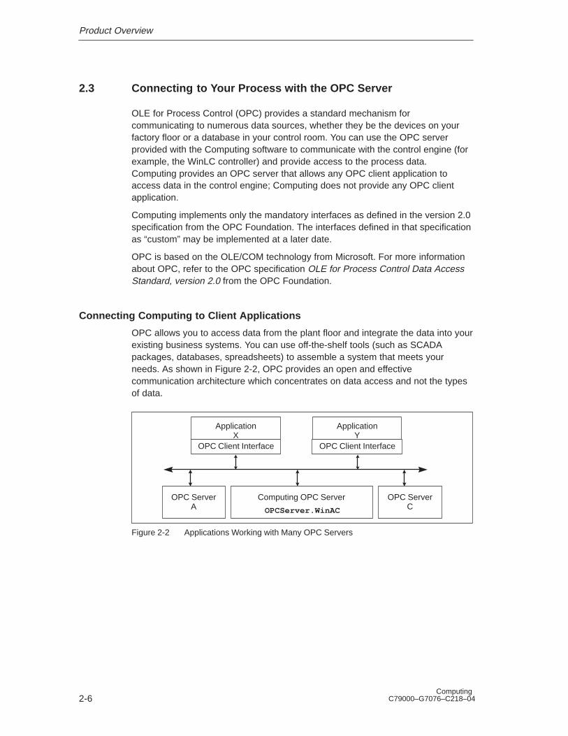
Connecting Computing to Client Applications
OPC allows you to access data from the plant floor and integrate the data into yourexisting business systems. You can use off-the-shelf tools (such as SCADApackages, databases, spreadsheets) to assemble a system that meets yourneeds. As shown in Figure 2-2, OPC provides an open and effectivecommunication architecture which concentrates on data access and not the typesof data.
OPC Client Interface OPC Client Interface
OPC ServerA
Computing OPC Server
OPCServer.WinAC
OPC ServerC
ApplicationX
ApplicationY
Figure 2-2 Applications Working with Many OPC Servers
Product Overview
2-7Computing C79000–G7076–C218–04
Your OPC client connects to the OPC server object provided by Computing. Thisconnection allows you to create and manipulate OPC group objects, whichorganize the data to be accessed. You can activate or deactivate a group as a unit,or you can “subscribe” to the list in a group of items so that you can be notifiedwhen the data change. (A group is a collection of items, like MB0.) Figure 2-3shows the connection from the OPC client application through WinAC to theprocess data.
Third-party OPC client application
Distributed I/O
WinAC
Computing: OPCServer.WinAC
Control engine
Figure 2-3 Using the OPC Server to Access Your Process Data
To access the OPC server and its contents, you must provide your OPC client withthe name (ProgID, or programmatic identifier) of the server object. The name ofthe OPC server object that is provided by Computing is: OPCServer.WinAC
For more information about the OPC server provided by Computing, refer to theOPC Server Interface Manual.
mpiProduct Overview
2-8Computing
C79000–G7076–C218–04
3-1Computing C79000–G7076–C218–04
Setting Up Computing Software
Chapter Overview
This chapter provides the following information:
� Section 3.1 lists the authorization requirements for installing and running theComputing software.
� Section 3.2 describes how to install the authorization.
� Section 3.3 describes how to install and uninstall the Computing software.
� Section 3.4 describes how to use the PG/PC Interface to connect Computing toa slot PLC or a communications card.
Section Description Page
3.1 Overview 3-2
3.2 Authorization 3-3
3.3 Installing and Uninstalling the Computing Software 3-5
3.4 Connecting Computing to a Slot PLC or Communications card 3-7
3
Setting Up Computing Software
3-2Computing
C79000–G7076–C218–04
3.1 Overview
The Computing software provides ActiveX controls, which you can use to create atailored view into your process. Computing lets you use any mix of S7 andthird-party ActiveX controls not only to view, but also to modify, process data.
Follow the guidelines below for authorization for your Computing software.
� For WinAC Basis, use the WinAC authorization
� For SIMATIC Net, use the SIMATIC Net authorization
� For upgrading WinAC Pro with Computing 3.0 standalone, use the Computingauthorization
� For standalone, use the Computing authorization.
Note
To run Computing on a different PC than the WinLC, you must purchase SIMATICComputing standalone.
Setting Up Computing Software
3-3Computing C79000–G7076–C218–04
3.2 Authorization
Computing requires a product-specific authorization (or license for use). Thesoftware is therefore copy-protected and can be used only if the relevantauthorization for the program or software package has been found on the hard diskof the computer.
Note
If you remove the authorization, Computing continues to operate; however, anotification message appears every six minutes to alert you that the authorizationis missing.
Authorization Disk
An authorization diskette is included with the software. It contains the authorizationand the program (AUTHORSW) required to display, install, and remove theauthorization.
There are separate authorization diskettes for each of the SIMATIC automationsoftware products. You must install the authorization for each product as part ofthe installation procedure for that software.
!Caution
If improperly transferred or removed, the authorization for Computing may beirretrievably lost.
The Readme file on the authorization diskette contains guidelines for installing,transferring, and removing the authorization for Computing. If you do not followthese guidelines, the authorization for Computing may be irretrievably lost. Losingthe authorization would prohibit you from modifying any program that wasdownloaded to Computing and from downloading another program to theComputing.
Read the information in the Readme file on the authorization diskette, and followthe guidelines in regard to transferring and removing the authorization.
Setting Up Computing Software
3-4Computing
C79000–G7076–C218–04
Installing the Authorization
When you install your software for the first time, a message prompts you to installthe authorization. Use the following steps to install the authorization for Computing.
1. When prompted, insert the authorization diskette in drive A.
2. Acknowledge the prompt.
The authorization is transferred to the hard drive (C), and your computer registersthe fact that the authorization has been installed.
Note
Always enter drive C as the destination drive for the authorization for Computing.
If you attempt to start Computing and there is no authorization available for thesoftware, a message informs you of this. If you want to install the authorization,use the AUTHORSW program on the authorization diskette. This program allowsyou to display, install, and remove authorizations.
Removing an Authorization
If you should need to repeat the authorization, for example, if you want to reformatthe drive on which the authorization is located, you must remove the existingauthorization first. You need the original authorization diskette to do this.
Use the following steps to transfer the authorization back to the authorizationdiskette:
1. Insert the original authorization diskette in your floppy disk drive.
2. Start the program AUTHORSW.EXE from the authorization diskette.
3. From the list of all authorizations on drive C, select the authorization to beremoved.
4. Select the menu command Authorization � Transfer... .
5. In the dialog box, enter the target floppy drive to which the authorization will betransferred and confirm the dialog box.
6. The window with the list of authorizations remaining on the drive is thendisplayed. Close the AUTHORSW program if you do not want to remove anymore authorizations.
You can then use the diskette again to install an authorization. You must use theauthorization diskette to remove any existing authorizations. If you need to removeComputing completely, you must remove the DP authorization.
If a fault occurs on your hard disk before you can back up the authorization,contact your local Siemens representative.
Setting Up Computing Software
3-5Computing C79000–G7076–C218–04
3.3 Installing and Uninstalling the Computing Software
The Computing software includes a Setup program that executes the installationautomatically. Prompts on the screen guide you step by step through theinstallation procedure.
Note
You must have administrator (“ADMIN”) privileges to install the Computingsoftware.
Starting the Installation Program
The Setup program guides you step by step through the installation process. Youcan switch to the next step or to the previous step from any position. To start theinstallation program, proceed as follows:
1. Insert the CD-ROM in your computer.
2. Use the Windows NT Start menu (select the Start � Run menu command) toopen the “Run” dialog box.
3. Click on the “Browse” button on the “Run” dialog box and select the installationprogram (Setup.exe) on the CD-ROM.
4. Click on the “Open” button to enter the Setup.exe program into the “Run” dialogbox.
5. Click on the “OK” button to start the installation program.
6. Follow the instructions displayed by the installation program.
To install only the Computing software, deselect the other components.
7. When prompted by the software, enter the registration number.
Once the installation has completed successfully, a message to that effect isdisplayed on the screen.
If an Older Version of Computing Is Already Installed
If the installation program finds another version of the Computing software on theprogramming device, the program reports this and prompts you to decide how toproceed by offering the following choices:
� Abort the installation so that you can uninstall the older version of theComputing software under Windows NT and then start the installation again.
� Continue the installation and overwrite the older version with the new version.
Setting Up Computing Software
3-6Computing
C79000–G7076–C218–04
Your software will be better organized if you uninstall any older versions beforeinstalling the new version. Overwriting an old version with a new version has thedisadvantage that if you then uninstall, any remaining components of the oldversion are not removed. If you uninstall the older version of Computing, you mustreboot your computer before installing the new version.
Troubleshooting Any Errors That Occur During Installation
The following errors may cause the installation to fail:
� Initialization error immediately after starting Setup: The Setup.exe program wasprobably not started under Windows NT.
� Not enough memory: You need at least 20 Mbytes of free space on your harddisk.
� Bad disk: Verify that the disk is bad, then call your local Siemensrepresentative.
� Operator error: Start the installation again and read the instructions carefully.
Uninstalling the Computing Software
Use the following procedure to remove the Computing software from yourcomputer:
1. Start the dialog box for installing software under Windows NT by double-clickingon the “Add/Remove Programs” icon in the Control Panel.
2. Select the Computing entry in the displayed list of installed software. Click onthe “Add/Remove...” button to uninstall the software.
Setting Up Computing Software
3-7Computing C79000–G7076–C218–04
3.4 Connecting Computing to a Slot PLC or Communications Card
To connect Computing to a slot PLC or communications card, you must define thenetwork connection over which Computing and the PLC or card communicate bysetting the PG/PC Interface.
Note
You can only view one slot PLC or one communications card at a time.
Follow these steps to configure Computing for communicating with a slot PLC orcommunication card:
1. From the Windows NT Start menu, select Start � Simatic PC Based Control� WinCP Configurator .
2. Select the the Connection tab, then click on the Setting the PG/PC Interfacebutton. The PG/PC Interface dialog box appears.
✂
Cancel HelpOK
InterfacesInstall...
Access PathAccess Point of Application:Micro/WIN ––>PC/PPI cable (PPI)(Standard for Micro/WIN)Interface Parameter set used:PC/PPI cable (PPI)MPI–ISA on board (MPI)
(Assigning Parameters to a PC/PPI Cablefor a PPI Network)
Setting the PG/PC Interface
✂
Cancel HelpOK
Interfaces
Access Path
Access Point of the Application:
Computing ––> CPU416–2 DP ISA card (local)
(Standard for STEP 7)
Interface Parameter Assignment Used:
CP416–2 DP ISA (local)CP5611 (PROFIBUS)CP5412A2(MPI)CP5412A2(PROFIBUS)PC Internal (local)TCP/IP––>3Com Etherlink III Adapter
Properties...
Delete
Copy...
Communication with WinAC components in thisPG/PC)
Set the PG/PC Interface (V5.0)
Add/Remove: Select...
CP416–2 DP ISA (local)
Figure 3-1 Setting the PG/PC Interface for Slot PLC CPU 416–2 DP ISA (local)
3. From the “Access Point of Application” drop-down list, select Computing.
4. Select the interface parameter from the parameter set that corresponds to yournetwork communications path, for example “CPU416–2 DP ISA (local)”. ThePLC or card you selected appears in the Access Point of the Application field(Figure 3-1).
Setting Up Computing Software
3-8Computing
C79000–G7076–C218–04
To set the Computing interface setting for a local slot PLC, select: COMPUTING –> <cardname> (local)
To set the Computing interface setting for an S7 system on a TCP/IP LAN, select:COMPUTING –> <cardname> (TCP/IP)
To set the Computing interface setting for an S7 system on an Industrial Ethernetnetwork (ISO Transport protocol), select: COMPUTING –> <cardname> (ISOTransport)
To set the Computing interface setting for an S7 system on a PROFIBUS network,select COMPUTING –> <cardname>(PROFIBUS).
4-1Computing C79000–G7076–C218–04
Using Computing to Access Data
Chapter Overview
Computing allows you to access data from control engines (either WinLC of WinACBasis, a slot PLC such as the CPU 416–2 DP ISA of WinAC Pro, or other S7PLCs. These control engines can be installed on the same computer asComputing, or Computing can use the local area network to access the controlengine.
Note
The term “slot PLC” in the manual refers to a slot PLC such as CPU 416–2 DPISA or CPU 416–2 DP ISA Lite. In the manual, the CPU416–2 DP ISA Lite istreated identically to the CPU416–2 DP ISA.
Computing allows you to communicate across a local area network using WindowsNT’s Distributed Component Object Model (DCOM). You use DCOM to integratedistributed applications by way of a LAN. A distributed application consists ofmultiple processes or different computers that cooperate to accomplish a singletask.
Computing can also communicate with a local or remote control engine in an MPI,PROFIBUS–DP, or H1 network. You can use the PG/PC Interface to set upconnection with the control engine.
Section Description Page
4.1 Accessing Data in Control Engines 4-2
4.2 Accessing a Local Control Engine 4-4
4.3 Accessing a Remote Control Engine 4-5
4.4 Communicating with Multiple Control Engines 4-6
4
Using Computing to Access Data
4-2Computing
C79000–G7076–C218–04
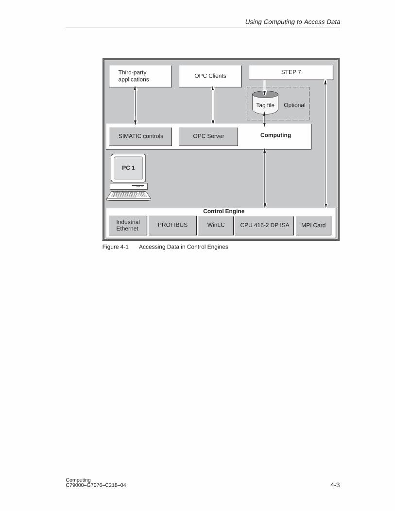
4.1 Accessing Data in Control Engines
A “control engine” is a processor or program that manages and manipulates datawhich is used to control a process or machine. The control engine can be eithersoftware or hardware. As shown in Figure 4-1, the elements of the Computingsoftware allow you to access data in the following control engines:
� Windows Logic Controller (WinLC), a software-based S7 controller that runs onthe RAM of your computer. WinLC communicates with I/O modules over aPROFIBUS–DP network. With release 3.0, SIMATIC Computing can alsoaccess data in WinLC over PROFIBUS–DP, MPI, and H1 networks.
� A slot PLC such as the CPU 416-2 DP ISA, an S7 controller built on an ISAcard that is installed in your computer. This CPU communicates with I/Omodules over a PROFIBUS network.
� Other S7 CPU modules on an MPI, H1, or PROFIBUS network. These CPUshave local and distributed (remote) I/O.
Computing provides SIMATIC controls that utilize Microsoft’s ActiveX technology toallow third-party applications (such as Microsoft’s Excel or Visual Basic) to accessdata in the control engine. In addition to these SIMATIC controls, Computingprovides a server that allows other applications to use an OPC (OLE for ProcessControl) interface.
Using a tag file, you can access the data symbolically on a PC where STEP 7 isnot installed. The TagFile Configurator creates a tag file from the symbol table ofSTEP 7. The tag file also provides you with the capability to connect yourapplication to more than one control engine simultaneously. (See Section 4.4.)
Using Computing to Access Data
4-3Computing C79000–G7076–C218–04
PC 1
Control Engine
MPI CardCPU 416-2 DP ISA
OPC ClientsThird-partyapplications
OptionalTag file
ComputingSIMATIC controls OPC Server
STEP 7
WinLCPROFIBUSIndustrialEthernet
Figure 4-1 Accessing Data in Control Engines
Using Computing to Access Data
4-4Computing
C79000–G7076–C218–04
4.2 Accessing a Local Control Engine
The basic configuration for Computing is to have all of the elements running onone computer, as shown in Figure 4-2. All of the software runs on the localcomputer, and access between the applications is simplified.
Using a tag file, you can access the data in the control engine by using symbolsinstead of absolute addresses. As shown in Figure 4-2, your application programcould use the symbol “Fill_Valve” to access I 0.0 and the symbol “Drain_Valve” toaccess I 0.1 in the control engine. You use the symbol table in STEP 7 to createthe tag file—the same symbol table that you created when you created theprogram for the control engine.
The tag file also provides you with the capability to connect your application tomore than one control engine simultaneously. For information about connecting tomultiple control engines, see Section 4.4.
For more information about creating tag files, see Chapter 9.
Third-party application
Process
PC 1
I/O
Control Engine
Computing
OptionalTag file
STEP 7
Fill_ValveI 0.0
Drain_ValveI 0.1
Figure 4-2 Accessing a Local Control Engine
Using Computing to Access Data
4-5Computing C79000–G7076–C218–04
4.3 Accessing a Remote Control Engine
You can also use Computing to access control engines on remote computers thatare part of your local area network (LAN). As shown in Figure 4-3, a third-party orcustom application which is running on PC 2 can access data in the control enginewhich is running on PC 1.
Using a tag file, you can access the data in the control engine by using symbolsinstead of absolute addresses. As shown in Figure 4-2, your application programcould use the symbol “Fill_Valve” to access I 0.0 and the symbol “Drain_Valve” toaccess I 0.1 in the control engine. You use the symbol table in STEP 7 to createthe tag file—the same symbol table that you created when you created theprogram for the control engine.
To use symbols with the application running on the remote computer, you mustcopy the tag file to the remote computer. The remote computer does not requireSTEP 7 or the symbol table to use the tag file.
For more information about creating tag files, see Chapter 9.
I/O
Process
PC 1
Optional
Tag file
STEP 7Computing
Fill_ValveI 0.0
Drain_ValveI 0.1
PC 2
Optional
Tag file
Third-party application
Network
Control Engine
Computing
Figure 4-3 Accessing a Remote Control Engine
Using Computing to Access Data
4-6Computing
C79000–G7076–C218–04
4.4 Communicating with Multiple Control Engines
You can use Computing over a local area network to access several controlengines simultaneously. By creating a tag file, you can configure the Data controlto access data on multiple control engines.
Note
You can only view one slot PLC or one communication card at a time
By utilizing Microsoft’s DCOM technology and/or other Siemens networks, a tag fileallows you to access a variety of control engines and applications throughout yourlocal area network. As shown in Figure 4-4, a computer running Computing (PC 1)can use a tag file to access data in the control engines running on anothercomputer (PC 2), as well as a third-party application (such as Microsoft’s Excel orVisual Basic).
As with a single control engine (see Sections 4.2 and 4.3), the tag file alsoprovides the capability for using symbols to access the data in the various controlengines.
See Appendix E for information about using DCOM to connect Computing tomultiple control engines. For more information about tag files and the TagFileConfigurator, see Chapter 9.
Using Computing to Access Data
4-7Computing C79000–G7076–C218–04
Process 1
PC 1
Third-party application
I/O
I/O
Tag file
Control Engine
Process 2
PC 2
Network
Control Engine
Computing
ComputingTag file
Figure 4-4 Accessing Data in Several Remote Control Engines
5-1Computing C79000–G7076–C218–04
Accessing the Process Data with the DataControl
Chapter Overview
The Data control provides the connection between your ActiveX controls and thecontrol engine (for example, WinLC or a slot PLC such as theCPU 416-2 DP ISA).
The Data control has specific properties that you can configure:
� For the SoftContainer provided by SIMATIC Computing: double-clicking on theData control displays the Properties dialog box. This dialog box contains thefollowing tabs: General, Engine, Connections, Events, and Name.
� For other container applications (such as Microsoft Visual Basic): access theproperties as for any other control in that container (for example, by using theright mouse button). Open the context menu for the Data control by clicking theright mouse button and selecting the Properties menu command.
Section Description Page
5.1 Connecting the SIMATIC Controls to the Control Engine 5-2
5.2 Configuring the Connection Properties for the Data Control 5-3
5.3 Selecting the Control Engine for the Data Control 5-4
5.4 Connecting the ActiveX Controls to the Control Engine 5-9
5.5 Filtering the Properties for the ActiveX Controls 5-13
5.6 Configuring Custom Events 5-15
5.7 Creating a Connection Table 5-16
5.8 Sample Program for Creating a Connection Table and an EventTable
5-17
5.9 Sample Program for Responding to Events 5-19
5.10 Sample Program for Reading and Writing Data 5-24
5.11 Sample Program for Reading and Writing Boolean Data 5-29
5.12 Properties, Methods, and Events of the Data Control 5-30
5
Accessing the Process Data with the Data Control
5-2Computing
C79000–G7076–C218–04
5.1 Connecting the SIMATIC Controls to the Control Engine
!Caution
Failing to disable the timers in your program could cause timer-generatedconnections to remain connected, allowing these connections to continue to writedata to the control engine. This could cause the control engine to operateerratically, which could potentially cause damage to equipment and injury topersonnel.
To ensure that all connections are disconnected when your program closes,always disable all timers before the End statement in the Form_Unload subroutine.
In order to access process data, the SIMATIC Computing controls (Button, Edit,Label, and Slider) must first establish a connection through the Data control.Figure 5-1 shows the relationship between the Data control and the other SIMATICcontrols.
Note
The Panel control (available with WinLC or a slot PLC) and the DBuffer control (foraccessing the diagnostics buffer of S7 controllers) do not use the Data control forconnecting to the control engine.
You use the “Connections” tab of the Data control to assign a variable (the memorylocation) to the Value property of each control. The Data control configures thecontrol engine to check the memory locations of the assigned variables at aspecified rate (in milliseconds). If there is a change in the value, the new value iswritten to the Data control. The Data control then writes the new value to the othercontrols.
OPC Client
Computing
OPC Server
Button control
Edit control
Third-party control
Label control
Data control
Control engine (such as WinLC)
Distributed I/O
Slider control
Figure 5-1 Using the Data Control for Connecting to a Control Engine
Accessing the Process Data with the Data Control
5-3Computing C79000–G7076–C218–04
5.2 Configuring the Connection Properties for the Data Control
As shown in Figure 5-2, the “General” tab allows you to configure the followingparameters for the connection to the control engine:
� AutoConnect (automatic connection): when this option is enabled, the Datacontrol automatically connects to the memory locations in the control engine.When this option is disabled, the Data control connects to the memory locationsonly when instructed by the program code (using a Connect method) that youassociated with the control.
� AutoConnect Timeout: time-out (in milliseconds) for the automatic connection:specifies the amount of time that the Data control waits between connecting tothe control engine and writing data.
Some containers may not provide a mechanism for telling the Data control towrite to the control engine. After the time-out that you specify, the Data controlstarts writing data.
� Default Update Rate (ms): specifies the rate (in milliseconds) that the controlengine checks the memory locations to see if change has occurred.
� Default Dead Band: specifies to the control engine the amount of change thatmust occur in a value before the control engine writes the new value to the Datacontrol. For example: if the dead band is 10 and the value in the control engineis 22, then the control engine does not write a new value until the valuebecomes either 33 or 11.
� Show Error Boxes: specifies whether to display the default error boxes whenthere is a user-generated error. Computing provides error messages in Englishonly. If you want to display messages in other languages, you must deselectthis option and write program code to react on the error event.
Siemens SIMATIC DataControl Properties
Connections EventsGeneral
100
100
AutoConnect Timeout (ms):
Default Update Rate (ms):
0Default DeadBand:
AutoConnect:
Show Error Boxes:
OK Cancel Apply Help
Engine Name
Figure 5-2 Data Control Properties (General Tab)
Accessing the Process Data with the Data Control
5-4Computing
C79000–G7076–C218–04
5.3 Selecting the Control Engine for the Data Control
Computing allows you to connect either to a single control engine or to severalcontrol engines. You can also connect to the control engine over a network, suchas a local area network (LAN). Use the “Engine” tab (Figure 5-3) of the “Properties”dialog box to select the control engine.
Siemens SIMATIC DataControl Properties
Connections EventsGeneral
Tag Source
Connection via Tag Source
OK Cancel Apply Help
Engine
Direct Connection
PC Name
Control Engine
Browse
Name
WinLC
Figure 5-3 Data Control Properties (Engine Tab)
A control engine may be either a slot PLC, such as the CP 416-2 DP ISA, an S7CPU, or WinLC. The control engine strings for the Data Control are of two types:
� Direct to WinLC
� Over a Siemens network
The control engine string for a direct connection to WinLC is WinLC . It is a COMconnection; you do not need to use the PG/PC Interface to configure it.
Connections for the following network types are configured using the PG/PCInterface settings are as follows:
� access to MPI network: COMPUTING––> <cardname> (MPI)
� access to DP network: COMPUTING––> <cardname> (PROFIBUS)
� access to H1 network: COMPUTING––> TCP/IP––> <cardname> (For accessto the network, the NCM option package and STEP 7 v5 SP3 must beinstalled.)
Accessing the Process Data with the Data Control
5-5Computing C79000–G7076–C218–04
Note
To use WinLC as a control engine, you must also set up the connection in WinLC.Refer to the chapter on connecting STEP 7 to WinLC or PLCs in the SIMATICWindows Logic Controller (WinLC) Manual for directions.
Using a Tag File
The tag file (or tag source) provides symbolic identification that can be used by theData control to access data or control engines. Using a tag file provides thefollowing capabilities:
� You can connect the Data control to several different control engines at thesame time.
� You can use the symbols defined in STEP 7 to access memory locations in thecontrol engine.
The tag file also provides a completion aid for entering the symbols. For moreinformation about tag files, see Chapter 9.
For more information about connecting to multiple control engines, seeSection 4.4. See Section 9.1 for information about using STEP 7 and the TagFileConfigurator for connecting to remote control engines.
Use the following procedure to connect the Data control to the control enginewhich is specified in a tag file:
1. Double-click on the Data control (or use the Edit � Properties menu command)to display the “Properties” dialog box for the Data control.
2. Click on the “Engine” tab to display the configuration choices.
3. Select the “Connection via Tag Source” option.
4. As shown in Figure 5-4, click on the “Browse” button and select the valid tag file(*.tsd).
5. Click on the Apply button to configure the Data control for using the specifiedtag file for connecting to the control engine.
Accessing the Process Data with the Data Control
5-6Computing
C79000–G7076–C218–04
Siemens SIMATIC DataControl Properties
Connections EventsGeneral
Tag Source
Connection via Tag Source
OK Cancel
Engine
Direct Connection
PC Name
Control Engine WinLC
Browse
Click on the Browse button toselect a specific tag file for theSIMATIC controls
Name
Figure 5-4 Selecting a Tag File for the Data Control
Connecting to a Specific Control Engine
As shown in Figure 5-5, you can use the Data control to connect your program to acontrol engine residing either on a local computer or on a different computer.
If you are connecting to a control engine over a LAN via DCOM, you must alsospecify the network name of the server PC in the “PC Name” field.
If you select the “Direct Connection” option, you must specify the name of thecontrol engine in the control engine field. The control engine strings now supportrack and slot location of the CPU at the network node, and include H1 networks,both IP and MAC addresses. Enter the following strings in the “Control Engine”field:
� <local> (to specify the control engine located on the same computer as theComputing software)
� WinLC (to specify the WinLC of WinAC Basis)
� wcS7=3 (to specify a slot PLC such as the CPU 416-2 DP ISA of WinAC Pro)
� wcS7=xx,a,b (to specify other PLCs on the MPI network, where xx is the MPIaddress, a is the rack number, and b is the slot number.) Note that WinLC isalways assigned rack 0, slot 2.
� wcIP=xxx.xxx.xxx.xxx,a,b for a control engine on a TCP/IP LAN orwcMAC–xx.xx.xx.xx.xx.xx,a,b for a control engine on an Industrial Ethernetnetwork with STEP 7 v5 SP3. Refer to Appendix G for more information aboutcontrol engine strings.
Some strings have been simplified for easier entry, but Data Control will acceptlonger strings used by applications that were created with previous versions ofComputing (for example, S7DosIntf\MPI=3).
Accessing the Process Data with the Data Control
5-7Computing C79000–G7076–C218–04
DCOMData control
Other ActiveX controlsPC 1
Data control
Other ActiveX controls
Control Engine
<local>
Direct Connection on a Remote Computer
Control Engine
PC 2
Direct Connection on a Local Computer
Figure 5-5 Direct Connection for a Local or a Remote Computer
Note
When you configure the Data control to connect to a single (specific) controlengine, you cannot connect a tag file. This means that you cannot use symbolnames for the variables in the control engine.
To use symbol names, select the option for connecting to multiple control enginesand browse to a tag file that contains symbols for only one control engine.
Use the following procedure to configure the Data control for connecting to aspecific control engine:
1. Double-click on the Data control (or use the Edit � Properties menu command)to display the “Properties” dialog box for the Data control.
2. Click on the “Engine” tab to display the configuration choices.
3. Select the “Direct Connection” option. See Figure 5-6.
4. To connect to a control engine on the local computer, enter <local> in the “PCName” field. Note that you cannot access WinLC and a slot PLCsimultaneously.
To connect to a control engine on a remote computer:
– In the “PC Name” field, enter the network name of server computer (forexample, “PC_2”).
– In the “Control Engine” field, enter the name of the control engine, such asWinLC or wcS7=3 (for a slot PLC such as the CPU 416-2 DP ISA ofWinAC Pro).
Accessing the Process Data with the Data Control
5-8Computing
C79000–G7076–C218–04
5. Click on the “Apply” button to configure the Data control.
Siemens SIMATIC DataControl Properties
Connections EventsGeneral
Tag Source
Connection via Tag Source
OK Cancel Apply Help
Engine
Direct Connection
PC Name
Control Engine wcS7=3
Browse
PC_2
Name
Select “Direct Connection” and enter thename of the server computer and thecontrol engine
Figure 5-6 Configuring DCOM for a Specific Control Engine
Note
To connect to a remote computer via LAN, you must have configured the differentcomputers for DCOM. See Sections E.2 and E.3 for information about configuringthe server and client computers for DCOM.
Accessing the Process Data with the Data Control
5-9Computing C79000–G7076–C218–04
5.4 Connecting the ActiveX Controls to the Control Engine
The Connections tab shows the ActiveX controls (whether they are SIMATICcontrols or third-party) that can be connected to the control engine.
!Caution
Using the timer function improperly or using breakpoints in Visual Basic withComputing can cause problems that could potentially cause your computer orapplication to crash or lock up. Depending on the configuration, this could causethe application to lose communication with the control engine. This could causeunpredictable process operation, which could result in death or serious injury topersonnel, and/or damage to equipment.
Always install a physical emergency stop circuit for your machine or process.
Concerning VB timers: The Timer function in Visual Basic version 5 allows atimer to interrupt code in progress within the same thread, which can causeproblems with potentially serious consequences. If you use VB timers withComputing, observe the following guidelines:
� Always kill (disable) the timers in the Form_Unload subroutine. Otherwise, atimer can trigger an event while the VB program is shutting down; this conditioncould cause your computer or your application to crash, lock up, or to continuerunning invisibly.
� If you start your timer in the Form_Load subroutine, the timer event could occurbefore the other objects have been instantiated. In order to ensure that theobjects have been properly instantiated, always start a timer in the Form_Loadsubroutine with a large interval (such as 1 or 2 seconds) to allow the objects tobe properly instantiated. Subsequent timer intervals can be set to shorterintervals.
Assigning a Variable to a Property of a Control
To define a connection in the control engine, you assign a variable (memorylocation) in the control engine to a property of a control. See Figure 5-7.
Note
Computing does not allow you to write to timers in the control engine.
Use the following procedure to assign a variable in the control engine to a propertyof the control:
1. On the Connections tab of the Data control, select (click on) the name of theproperty.
Accessing the Process Data with the Data Control
5-10Computing
C79000–G7076–C218–04
2. In the “Assigned Variable” field, enter the memory address in the controlengine:
Note
If you have attached a tag file to the Data control, you can enter the symbolsinstead of the absolute addresses. You can also click on the “Browse” button tonavigate to the symbol. Entering a “.” (dot or period) displays a list of valid tag filesor symbols of each hierarchic level.
– If you selected the “Direct Connection” option for the control engine (notusing symbols), enter the absolute address (such as MB0) for the memorylocation in the control engine. See Appendix A for information about the datatypes and memory areas of the S7 controllers.
– If you selected the “Connection via Tag Source” option to use multiplecontrol engines (but are not using symbols), and the absolute address (suchas MB0) for the memory location in the default control engine. SeeAppendix A for information about the data types and memory areas of theS7 controllers. You can also append an absolute variable address to thesymbolic name of a control engine (for example, ce1.mb0, ce2.mb0). See“Using Absolute Addresses with a Tagfile” in Section 9.3 for informationabout setting the default control engine.
– If you selected the “Connection via Tag Source” option to use symbols(regardless of whether you are connecting either to a single control engineor to multiple control engines) enter the symbolic address for the memorylocation (such as Start_Program ). You can append the address to thesymbolic name of the control engine (such as PC_2_WinLC ).
3. Click on the “Apply” button to assign the variable to the property.
Siemens SIMATIC DataControl Properties
Connections EventsGeneral
Assigned Variable:
PC_2_WinLC.Start_Program
Browse...
100Update rate (ms):
Dead ban
Automati
Controls:
Add... Filter...
S7Data1
Button1
OK Cancel Apply Help
Engine
ApplDelete
After you select the property from thehierarchy, enter the memory locationof the variable to be assigned to thatproperty
Name
–
Enabled
FalseCaptionFalseColorFalsePicture
TrueCaptionTrueColor
ValueTruePicture
AlignmentAppearance
Border Style
FontForeColor
PushButtonLocked
StretchModeStyle
Figure 5-7 Entering a Symbol for the Assigned Variable
Accessing the Process Data with the Data Control
5-11Computing C79000–G7076–C218–04
If you identified a tag source or file, you can browse to a symbol for the variable.Click on the “Browse” button (as shown in Figure 5-8) and select the variable fromthe symbols listed for the tag source or file. Select a symbol or tag and pressEnter. (Figure 5-8 shows the property listing with a filter applied to display only theEnabled and Value properties. for more information about filtering the propertylisting, see Section 5.5.)
Siemens SIMATIC DataControl Properties
Connections EventsGeneral
Assigned Variable:
Browse...
100
0
Update rate (ms):
Dead band:
Automatic writ
Controls:
Add... Filter...
S7Data1
S7Soft1
Button2
Edit1
Button1
OK Cancel Apply Help
Engine
Apply filterDelete
EnabledValue
Click on the “Browse” button tofind a specific symbol name inthe tag file.
Name
Figure 5-8 Browsing to a Symbol in the Tag File
Entering Absolute Addresses Instead of Symbols
If you attached a tag file to the Data control, you can enter absolute addressesinstead of the symbols created by the symbol table of STEP 7. Click on the Browsebutton to navigate to the symbol. Entering a character in the Assigned Variablefield displays a list of valid symbols at the first level (a completion aid). Afterselecting one of these, entering a “.” (dot or period) displays symbols at the nextlevel. Use the following procedure to enter absolute addresses instead of symbolnames:
1. Type the first character of the absolute address.
2. Press the Esc (Escape) key.
3. Type the rest of the absolute address.
Accessing the Process Data with the Data Control
5-12Computing
C79000–G7076–C218–04
Adding a Connection
If you want to configure a connection for an ActiveX control before you place thecontrol into your ActiveX container, you can use the “Add” button to add aninstance of the control to the Controls list. Click on the “Add” button to specify theinstance that you want to connect to the Data control.
After you have added the ActiveX control instance to the Controls list, you canselect the instance from the list, choose the “Add” button again and add anyadditional properties. For instance, you could add an Edit control instance to theconnections list, and then add the Value property to the Edit control in order toassign a variable to the Edit control.
Deleting a Connection
If you remove a control from the ActiveX container, the connection remainsconfigured in the Data control. This means that the next time you place a control ofthe same name into the container, the connection that you configured for theprevious control of that name is automatically applied to the new control. Forinstance, if you remove a control called Edit1, and later insert a new Edit control,the default name for the new control is Edit1, and the new control inherits theexisting Edit1 connection. Use the “Delete” button if you want to prevent newcontrols from inheriting a previously configured connection: from the Controls list,select the instance whose connection you want to delete, and click on the “Delete”button.
Note
If you remove a control, or change your mind about adding a control after youhave already configured a connection for it using the “Add” button, you can onlydelete the connection to it if there is no control in the ActiveX container that usesthe name specified in the connection. Delete the connection before you add anyother control that uses the name that is specified in the connection. You cannotuse the “Delete” button to remove a connection to a control that is present in theActiveX container.
Accessing the Process Data with the Data Control
5-13Computing C79000–G7076–C218–04
5.5 Filtering the Properties for the ActiveX Controls
The Data control provides a filter that allows you to display a subset of theproperties for the controls. For example, you may want to display only the Enabledand Value properties and avoid scrolling through all of the other properties for eachcontrol.
Use the following procedure for filtering the properties:
1. Access the Properties dialog box for the Data control.
2. As shown in Figure 5-9, click on the “Filter” button.
Siemens SIMATIC DataControl Properties
Connections EventsGeneral
Assigned Variable:
100
0
Update rate (ms):
Dead band:
Automatic write mode:
Controls:
Add... Filter...
S7Data1
S7Soft1
Button2
Edit1
Edit2
Button1
OK Cancel Apply Help
Engine
Apply filter to propertiesDelete
Click on the “Filter” button to selectthe properties to be displayed
Name
Figure 5-9 Data Control Properties (Connections Tab)
3. As shown in Figure 5-10, enter the properties to display and click on the “Add”button. Use the “Edit” button to correct entries and the “Delete” button toremove entries.
4. As shown in Figure 5-11, select the “Apply filter to properties” check box todisplay only the properties listed in the filter.
Use the “Apply filter to properties” check box to toggle the filter on and off.
Accessing the Process Data with the Data Control
5-14Computing
C79000–G7076–C218–04
Siemens SIMATIC DataControl Properties
Connections EventsGeneral
100
0
Controls:
Add...
S7Data1
S7Soft1
But
Edi
Edi
But
OK Cancel Apply Help
Engine
properties
Name
mode:
Property Filter
Visible Properties:
Add... Delete
Enabled
OK Cancel
Edit
Value
Click on the “Add” button to enter aproperty to the filter
Figure 5-10 Data Control Properties (Connections Tab)
Siemens SIMATIC DataControl Properties
Connections EventsGeneral
Assigned Variable:
Browse...
Update rate (m
Dead band:
Automatic write mode:
Controls:
Add... Filter...
S7Data1
S7Soft1
Button2
Edit1
Button1
OK Cancel Apply Help
Engine
Apply filter to propertiesDelete
EnabledValue
Click on the check box to togglethe property filter on and off
Edit1
Name
Figure 5-11 Data Control Properties (Connections Tab)
Accessing the Process Data with the Data Control
5-15Computing C79000–G7076–C218–04
5.6 Configuring Custom Events
As shown in Figure 5-12, the “Events” tab allows you to add custom events thatare triggered by the Data control. You enter a key (string) and assign that key to amemory location (variable). If that variable changes, then the Data controlgenerates an event with a parameter that contains the string that you entered inthe “Key” field. Your program can then react to this event.
See Section 5.9 for a sample program that responds to events in the CPU.
Siemens SIMATIC DataControl Properties
Connections EventsGeneral
Assigned Variable:
m17.3
Browse...
100
0
Update rate (ms):
Dead band:
Keys:
S7Soft1
S7Data1
Add... Delete
OK Cancel Apply Help
OverflowWarning
Engine Name
Figure 5-12 Data Control Properties (Events Tab)
Adding an Event
The “Add” button allows you to add user-specified events for controller valuechanges. You can write your own code to handle the event by handling theValueChanged event of a Data control. Select a Data control from the expandablelist under the “Keys” field and click on the “Add” button; then type any name youchoose for the event (for example, OverflowWarning). Next, type a variable in the“Assigned Variable” field to identify the process value that causes the event to befired.
Figure 5-12 shows an sample event that has been added. A change in the value ofM17.3 calls the event handler for the Data control. The input to the event handler isthe text string OverflowWarning .
Deleting an Event
To delete a user-specified event, expand the list under “Keys,” select the desiredevent, and click on the “Delete” button.
Accessing the Process Data with the Data Control
5-16Computing
C79000–G7076–C218–04
5.7 Creating a Connection Table
The Data control uses a connection table for determining which properties of thevarious controls are connected to a specific memory locations of the controlengine. Each connection table contains an entry for each connection. Each entrycontains the following information:
� Property name: this field identifies the property that has an assigned variable.
� Data source: this field identifies the memory location in the control engine forthe connection.
� Update rate: this field defines the update rate for the connection. If no value isentered in this field, the Data control uses the default update rate (which is thevalue stored in the DefaultUpdateRate property).
� Dead band: this field defines the dead band for automatically writing to thecontrol engine or the control. If no value is entered in this field, the Data controluses the default update rate (which is the value stored in the DefaultDeadBandproperty).
When you use the “Properties” dialog box to configure the Data control, the Datacontrol automatically creates a connection table. You can also create a program tomanually create connection tables. See Section 5.8 for a sample program formanually creating a connection table.
Accessing the Process Data with the Data Control
5-17Computing C79000–G7076–C218–04
5.8 Sample Program for Creating a Connection Table and an EventTable
You can write a program to create a table to define the connections (assignedvariables) or events for the control engine.
Using a Connection Table
You can create a connection table to assign a variable in the control engine to aspecific control. The connection table corresponds to the “Connections” tab on the“Properties” dialog box of the Data control.
For each element in the connection table, you must define the property in thecontrol for the connection, the source (memory location of the assigned variable inthe control engine), the update rate, and the dead band value. In order toprogrammatically change connections with a connection table, you must firstdisconnect the data control (ending all connections) before you can reassignconnections and reconnect the Data control.
Note
Instead of creating a connection table, consider using the read and write methodsfor the Data control (ReadVariable, ReadMultipleVariables, WriteVariable, andWriteMultipleVariables). These methods allow you to access more data with justone line of code.
Table 5-1 shows sample Visual Basic code for a Label control called lblChange inyour form to MW2 in the control engine. The value stored in MW2 displays as thecaption in the label control.
Table 5-1 Sample Program for Manually Creating a Connection Table
Visual Basic Code
Dim ControlTable (4) As String
’Define a connection table for lblChangeControlTable (0) = ”Caption” ’PropertyControlTable (1) = ”MW2:WORD” ’Source (memory location)ControlTable (2) = ”100” ’Update rateControlTable (3) = ”0.0” ’Dead band
’Attach the connection table to S7Data1’S7Data1.ConnectObject lblChange, ControlTable
’Connect to the control engineS7Data1.Connect ’Connects to the control engine
Accessing the Process Data with the Data Control
5-18Computing
C79000–G7076–C218–04
Using an Event Table
You can also create an event table to define events for the control engine. Theevent table corresponds to the “Events” tab of the “Properties” dialog box of theData control. Table 5-2 provides the sample Visual Basic code for creating anevent table.
Section 5.9 provides a sample program that responds to events. This sampleprogram uses an event table to define the events for control engine.
Table 5-2 Sample Program for Manually Creating an Event Table
You can create a program that responds to events in the control engine. In thissample program, eight lights correspond to the eight events which are defined in aconnection table. (See Figure 5-13.) The events are connected to the status ofmemory location MB0: a change in the value stored in MB0 generates a set ofevents (named for each bit in the byte).
As shown in Figure 5-13, the program also contains the following elements:
� Data control (S7Data4) for connecting to the control engine
� Timer (Timer1) that increments the value stored in MB0 (which then causes thecontrol engine to generate the events)
� Command button (cmdStartEvent) for starting or stopping the timer (therebystarting or stopping the generation of events)
Start Events
VB5 Programming ExampleLight(0) to Light(7): These VBobjects change color to displaythe events stored in MB0
Timer1: generates aReadVariable and WriteVariableat fixed intervals
S7Data4: Connects theseelements to the control engine
cmdStartEvent: This commandbutton starts (or stops) theevents
Figure 5-13 Sample Program for Responding to Events in the Control Engine
!Caution
Failing to disable the timers in your program could cause timer-generatedconnections to remain connected, allowing these connections to continue to writedata to the control engine. This could cause the control engine to operateerratically, which could potentially cause damage to equipment and injury topersonnel.
To ensure that all connections are disconnected when your program closes,always disable all timers before the End statement in the Form_Unload subroutine.
Accessing the Process Data with the Data Control
5-20Computing
C79000–G7076–C218–04
Creating a Connectio n Table for Responding to Events
Your program can create an event table to define specific events in the controlengine. Table 5-3 lists the code for creating a connection table for defining eventkeys for a control engine.
Table 5-3 Sample Program for Creating a Connection Table for Responding to Events
Responding to the Events Generated by the Sample Program
Table 5-4 provides sample Visual Basic code for responding to different eventsfrom the control engine.
Table 5-4 Sample Program for Responding to Events in the Control Engine
Visual Basic Code
Private Sub S7Data4_ValueChanged(ByVal Property As String, ByVal VarName As String,ByVal Value As Variant, ByVal Quality As Integer)
’Evaluates which event occurredSelect Case Property
Case ”M0_0” ’Event M0_0 turns Light(0) greenIf Value = True Then
Light(0).FillColor = vbGreenElse
Light(0).FillColor = vbRedEnd If
Case ”M0_1” ’Event M0_1 turns Light(1) greenIf Value = True Then
Light(1).FillColor = vbGreenElse
Light(1).FillColor = vbRedEnd If
Case ”M0_2” ’Event M0_2 turns Light(2) greenIf Value = True Then
Light(2).FillColor = vbGreenElse
Light(2).FillColor = vbRedEnd If
Case ”M0_3” ’Event M0_3 turns Light(3) greenIf Value = True Then
Light(3).FillColor = vbGreenElse
Light(3).FillColor = vbRedEnd If
Case ”M0_4” ’Event M0_4 turns Light(4) greenIf Value = True Then
Light(4).FillColor = vbGreenElse
Light(4).FillColor = vbRedEnd If
Case ”M0_5” ’Event M0_5 turns Light(5) greenIf Value = True Then
Light(5).FillColor = vbGreenElse
Light(5).FillColor = vbRedEnd If
Case ”M0_6” ’Event M0_6 turns Light(6) greenIf Value = True Then
Light(6).FillColor = vbGreenElse
Light(6).FillColor = vbRedEnd If
Accessing the Process Data with the Data Control
5-22Computing
C79000–G7076–C218–04
Table 5-4 Sample Program for Responding to Events in the Control Engine, continued
Case ”M0_7” ’Event M0_7 turns Light(7) greenIf Value = True Then
Light(7).FillColor = vbGreenElse
Light(7).FillColor = vbRedEnd If
End SelectEnd Sub
Running the Sample Program (Generating the Events in the Control Engine)
Table 5-5 provides sample Visual Basic code for changing the value stored in MB0.Changing the value of MB0 then causes the control engine to generate the eventsdefined in the connection table (Table 5-3).
� The command button (cmdStartEvents) starts or stops the timer (Timer1).
� The timer (Timer1) reads the value stored in MB0 of the control engine,increments the value, and writes the new value back to the control engine.
The changed value of MB0 causes the control engine to generate the events.
!Caution
Failing to disable the timers in your program could cause timer-generatedconnections to remain connected, allowing these connections to continue to writedata to the control engine. This could cause the control engine to operateerratically, which could potentially cause damage to equipment and injury topersonnel.
To ensure that all connections are disconnected when your program closes,always disable all timers before the End statement in the Form_Unload subroutine.
Accessing the Process Data with the Data Control
5-23Computing C79000–G7076–C218–04
Table 5-5 Other Subroutines for Running the Sample Program
Visual Basic Code
Private Sub cmdStartEvents_Click()If cmdStartEvents.Caption = ”Start Events” Then
You can write a program that initiates access to data (reading or writing) in thecontrol engine.
You can read or write single variables, multiple variables or arrays of variables.(For reading and writing Boolean data, you must use the ReadMultiVariablesmethod or WriteMultiVariables method. See Section 5.11.)
For information about the memory areas of the S7 controllers, see Appendix A.
!Caution
Using the timer function improperly or using breakpoints in Visual Basic withComputing can cause problems that could potentially cause your computer orapplication to crash or lock up. Depending on the configuration, this could causethe application to lose communication with the control engine. This could causeunpredictable process operation, which could result in death or serious injury topersonnel, and/or damage to equipment.
Always install a physical emergency stop circuit for your machine or process.
Concerning VB timers: The Timer function in Visual Basic version 5 allows atimer to interrupt code in progress within the same thread, which can causeproblems with potentially serious consequences. If you use VB timers withComputing, observe the following guidelines:
� Always kill (disable) the timers in the Form_Unload subroutine. Otherwise, atimer can trigger an event while the VB program is shutting down; this conditioncould cause your computer or your application to crash, lock up, or to continuerunning invisibly.
� If you start your timer in the Form_Load subroutine, the timer event could occurbefore the other objects have been instantiated. In order to ensure that theobjects have been properly instantiated, always start a timer in the Form_Loadsubroutine with a large interval (such as 1 or 2 seconds) to allow the objects tobe properly instantiated. Subsequent timer intervals can be set to shorterintervals.
Accessing the Process Data with the Data Control
5-25Computing C79000–G7076–C218–04
Reading a Single Variable in the Control Engine
Table 5-6 provides sample Visual Basic code for using the ReadVariable method ofthe Data control to read a single variable in the control engine.
Table 5-6 Reading a Single Variable from the Control Engine
Visual Basic Code
Private Sub ReadSingleRealVariableDim rc As LongDim name_s As StringDim value_v As VariantDim state_l As LongDim timeout_l As Long
’Read one Real (floating point) valuename_s = ”MD0:REAL”timeout_l = 0
’Display the value and return code in a List BoxListBox1.ClearListBox1.AddItem ”RetCode = ” & Hex(rc)ListBox1.AddItem ” – ” & name_s & ” = ” & value_vListBox1.AddItem ” – State = ” & Hex(state_l)
End Sub
Writing a Single Variable to the Control Engine
Table 5-7 provides sample Visual Basic code for using the WriteVariable method ofthe Data control to write a single variable to the control engine.
Table 5-7 Writing a Single Variable to the Control Engine
Visual Basic Code
Private Sub WriteSingleRealVariableDim rc As LongDim name_s As StringDim value_v As VariantDim timeout_l As Long
’Write one Real (floating point) valuename_s = ”MD0:REAL”value_v = (Rnd * 1000)timeout_l = 100
’Display the value and return code in a List BoxListBox1.ClearListBox1.AddItem ”Wrote ” & name_s & ” = ” & value_vListBox1.AddItem ”Return Code = ” & Hex(rc)
End Sub
Accessing the Process Data with the Data Control
5-26Computing
C79000–G7076–C218–04
Reading an Array in the Control Engine
Table 5-8 provides sample Visual Basic code for using the ReadVariable method ofthe Data control to read an array of data in the control engine.
Note
Read and write STRING or CHAR data as Visual Basic BSTR data. Do not use anarray of CHAR to emulate a STRING.
Use one BSTR for each STRING or CHAR, regardless of the length of the databeing accessed. For example:
� To access CHAR[50] (which designates 50 bytes or 50 characters), use aBSTR of up to 50 bytes and not 50 individual BSTRs.
� To access STRING[50] (which designates a string of 50 characters), use aBSTR of up to 50 bytes and not 50 BSTRs.
Table 5-8 Sample Program for Reading an Array of Variables
Visual Basic Code
Private Sub ReadArrayOfRealsDim rc As LongDim name_s As StringDim value_v As VariantDim state_1 As LongDim timeout_l As LongRandomize
’Read an array of Real (floating point) valuesname_s = ”MD0:Real[3]”timeout_l = 0
’Display the values and return codes for the array in a List BoxListBox1.ClearListBox1.AddItem ”Return Code = ” & Hex(rc)ListBox1.AddItem ” – name_s & “ = ” & value_v(0) & “ “ & value_v(1) & “ “ –
value_v(2)ListBox1.AddItem ” – State = ” & Hex(state_1)
End Sub
Accessing the Process Data with the Data Control
5-27Computing C79000–G7076–C218–04
Writing an Array to the Control Engine
Table 5-8 provides sample Visual Basic code for using the WriteVariable method ofthe Data control to write an array of data to the control engine.
Note
Read and write STRING or CHAR data as Visual Basic BSTR data. Do not use anarray of CHAR to emulate a STRING.
Use one BSTR for each STRING or CHAR, regardless of the length of the databeing accessed. For example:
� To access CHAR[50] (which designates 50 bytes or 50 characters), use aBSTR of up to 50 bytes and not 50 individual BSTRs.
� To access STRING[50] (which designtes a string of 50 characters), use aBSTR of up to 50 bytes and not 50 BSTRs.
Table 5-9 Sample Program for Writing an Array of Variables
Visual Basic Code
Private Sub WriteArrayOfRealsDim rc As LongDim name_s As StringDim timeout_l As LongDim value_b(2) As Byte ’ for byte writeDim value_w(2) As Integer ’ for word writeDim value_r(2) As Single ’ for real write
’Read an array of Real (floating point) valuesname_s = ”MD0:REAL[3]”value_r(0) = (Rnd * 1000)value_r(1) = (Rnd * 1000)value_r(2) = (Rnd * 1000)timeout_l = 100
’Display the values and return codes for the array in a List BoxListBox1.ClearListBox1.AddItem ”Return Code = ” & Hex(rc)ListBox1.AddItem ” – Wrote MD0:REAL[0] = ” & value_r(0)ListBox1.AddItem ” – Wrote MD0:REAL[1] = ” & value_r(1)ListBox1.AddItem ” – Wrote MD0:REAL[2] = ” & value_r(2)
End Sub
Reading Multiple Variables in the Control Engine
Table 5-10 provides sample Visual Basic code for using the ReadMultiVariablesmethod of the Data control to read multiple variables in the control engine.
Accessing the Process Data with the Data Control
5-28Computing
C79000–G7076–C218–04
Table 5-10 Reading Multiple Variables in the Control Engine
Visual Basic Code
Private Sub ReadMultiRealsDim i As IntegerDim rc As LongDim names_array(2) As StringDim values_v As VariantDim states_v As Variant
’Read three Real (floating point) valuesFor i = 0 To 2
Table 5-11 provides sample Visual Basic code for using the WriteMultiVariablesmethod of the Data control to write several variables to the control engine.
Table 5-11 Writing Multiple Variables to the Control Engine
Visual Basic Code
Private Sub cmdWriteMultVar_Click(Index As Integer)Dim i As IntegerDim rc As LongDim names_array(2) As StringDim values_v(2) As VariantDim states_v As Variant
’Write three Real (floating point) valuesFor i = 0 To 2
5.11 Sample Program for Reading and Writing Boolean Data
For reading and writing Boolean data, you must use the ReadMultiVariablesmethod or WriteMultiVariables method. Table 5-12 provides a sample program forreading and writing arrays of Boolean data.
Table 5-12 Reading and Writing Multiple Variables
Visual Basic Code
Private Sub Read_Booleans()Dim mybools(7) As StringDim vals_v As VariantDim states_v As VariantDim rc As Long
rc = S7Data1.WriteMultiVariables(mybools, myvals, states_v)End Sub
Accessing the Process Data with the Data Control
5-30Computing
C79000–G7076–C218–04
5.12 Properties, Methods, and Events of the Data Control
You use the properties and methods listed in Table 5-13 to manipulate the Datacontrol.
Table 5-13 Properties and Methods of the Data Control
Property or Method Description Page
Activated property Specifies whether or not all connections are activated B-1
AutoConnect property Specifies whether or not the configured connectionsare established at runtime
B-3
AutoConnectTimeoutproperty
Specifies a timeout value B-4
Connect method Establishes all configured connections B-7
ConnectName method Establishes connections for the object that isspecified by name
B-8
ConnectObject method Establishes connections for a specified object B-9
ControlEngine property Specifies the control engine for the connection
DefaultDeadbandproperty
Specifies the dead band used by the Data control, ifno dead band is specified in the connection table
B-12
DefaultUpdateRateproperty
Specifies the update rate used by the Data control, ifno update rate is specified in the connection table
B-13
Disconnect method Releases all established connections B-14
MultipleEngines property Specifies whether the connection is to one specificcontrol or to several control engines
B-27
PCName property Specifies the network identification for a remotecomputer (for connecting over a network)
B-28
PropertyChangedNamemethod
Notifies the Data control that the value of a propertyof a connected control, referenced by Name, haschanged
B-30
PropertyChangedObjectmethod
Notifies the Data control that the value of a propertyof a connected control, referenced by Object, haschanged
B-31
ReadMultiVariablesmethod
Reads the status of several variables in the controlengine
B-33
ReadVariable method Reads the status of one specific variable in thecontrol engine
B-33
ShowErrorBoxesproperty
Specifies whether to display the default error boxeswhen there is a user-generated error
B-36
TagSource property Specifies the source (such as a tag file) of symbolicinformation to be used when assigning variables andidentifying control engines
B-39
WriteMultiVariablesmethod
Writes new values to several variables in the controlengine
B-44
WriteVariable method Writes a new value to a specific variable in the controlengine
B-45
Accessing the Process Data with the Data Control
5-31Computing C79000–G7076–C218–04
The Data control responds to the events listed in Table 5-14.
Table 5-14 Events of the Data Control
Event Description Page
ConnectionError Occurs when an error on a connection occurs C-1
ValueChanged Occurs when the value of a connected variable changesand no connected event was specified on the call to theConnect method
C-9
Error Codes for the Data Control (ConnectionError Event)
When an error occurs in the Data control, the control generates a ConnectionErrorevent. Your program can capture this ConnectionError event and respond tospecific situations. The ConnectionError event can detect standard OLE errors,such as E_FAIL or E_OUTOFMEM. Table 5-15 lists some of the error codes.
Table 5-15 Data Control Error Codes
Error Code Description
0x80004005 General OLE failure
0x8007000E Out of available memory
0x80070057 Invalid variable syntax
0xC0040004 Invalid or unknown data type
0xC0040007 Invalid variable type
0xC0040008 Invalid syntax for the item definition
0xC004000B Value passed to WRITE is out of range
6-1Computing C79000–G7076–C218–04
User Controls
Chapter Overview
Computing provides ActiveX User controls for accessing process data. You use theProperties dialog box of the Data control to establish a connection between theuser control and the control engine. Each control has a properties dialog box fordefining the performance of the control.
� Button control allows you to turn individual bits of memory on and off.
� Edit control provides access to the memory locations of the control engine.
� Label control allows you to display a constant string.
� Slider control provides an interface for monitoring and modifying analogvariables.
Section Description Page
6.1 Connecting the User Controls to the Process Data 6-2
6.2 Using the Property Pages of the Button Control 6-4
6.3 Properties and Methods of the Button Control 6-9
6.4 Events of the Button Control 6-10
6.5 Using the Property Pages of the Edit Control 6-11
6.6 Properties and Methods of the Edit Control 6-18
6.7 Events of the Edit Control 6-19
6.8 Error Codes for the Edit Control 6-20
6-21 Using the Property Pages of the Label Control 6-21
6.10 Properties and Methods of the Label Control 6-26
6.11 Events of the Label Control 6-26
6.12 Using the Property Pages of the Slider Control 6-27
6.13 Properties and Methods of the Slider Control 6-34
6.14 Events of the Slider Control 6-35
6
User Controls
6-2Computing
C79000–G7076–C218–04
6.1 Connecting the User Controls to the Process Data
To establish a connection between a Button, Edit, or Slider control and yourprocess data, you assign a (single-bit) variable to the Value property of the control.To establish a connection between the Label control and your process data, youassign a (single-bit) variable to the Caption property of the Label control. Thevariable cannot be assigned within the Properties dialog box of the control.Instead, use the Properties dialog box of the Data control and select the buttonfrom the expandable list of controls under the Connections tab. See Figure 6-1.
To set properties for anything other than the Value property, you can use theProperties dialog box of the control itself. Use the Edit menu or right click themouse button and select the Properties command for the control.
Note
In order to connect the control to actual process data, you must establish aconnection through the Data control.
Siemens SIMATIC DataControl Properties
Connections EventsGeneral
Assigned Variable:
m0.0
Browse...
100
0
Update rate (ms):
Dead band:
Automatic write mode:
Controls:
Add... Filter...
S7Data1
Button1
OK Cancel Apply Help
Engine
Apply filter to propertiesDelete
Name
Enabled
FalseCaptionFalseColorFalsePicture
TrueCaptionTrueColor
ValueTruePicture
AlignmentAppearance
Border Style
FontForeColor
PushButtonLocked
StretchModeStyle
Figure 6-1 Assigning Variables for a Button, Edit, Control
Specifying Variables and Data Types
While Computing allows you to specify a data type when you assign a variable toone of the properties of an S7 control, remember that the Button control can be beassigned only to an individual bit in the control engine. The only valid data type fora Button control is BOOL.
User Controls
6-3Computing C79000–G7076–C218–04
As an option, Computing allows you to specify a data type when you assign avariable to one of the properties of a SIMATIC control. You define the data type byentering the absolute address for the memory location, followed by a colon (:) andthen the data type. Be careful in assigning data types. If you are connecting anEdit control, the values for some S7 datatypes will not display properly unless thedatatype you assign matches the Data Format field in the Edit Control propertiesbox. For example, you can define an assigned variable as a REAL data type byentering “MD100:real” when you assign the variable, but you must be sure to setthe Data Format field in the Edit Control properties box to Real.
Siemens SIMATIC DataControl Properties
Connections EventsGeneral
Assigned Variable:
md100:real
Browse...
100
0
Update rate (ms):
Deadband:
Automatic write mode:
Controls:
Add... Filter...
OK Cancel Apply Help
Engine
Apply filter to propertiesDelete
S7Data1
S7Number1
Name
BackColor
BorderStyleDataFormatDisplayValue
Value
AlignmentAppearance
BackStyle
EnabledFactor
ForeColorFont
Locked
Figure 6-2 Assigning Variables for the Edit Control
User Controls
6-4Computing
C79000–G7076–C218–04
6.2 Using the Property Pages of the Button Control
The Button control allows you to associate a button display with a data bit fromyour process. You associate the button with your process by assigning a variable(namely, the desired bit location) to it. You can then toggle the button display tochange the state of the bit; the button color also changes automatically as the stateof the bit changes within the process.
The Button control provides access to individual memory bits in the control engineand has two states of animation: 0 (off) or 1 (on). Clicking on the Button controlchanges the data in the control engine.
The Button control reads and writes Boolean (single bit) values.
Defining the Caption and Enabling the Control (Using the General Tab)
The General tab of the Properties dialog (see Figure 6-3) allows you to define thetwo captions for the Button control:
� “Alignment” determines the alignment of the text (left, center, or right).
� “TrueCaption”: Enter the text to be displayed in the control when the bit is “true”(equal to 1 or “on”).
� “FalseCaption”: Enter the text to be displayed in the control when the bit is“false” (equal to 0 or “off”).
� “Style” determines the style (standard or graphical) for the control. Graphicalstyle means that a bitmap is used.
� “Appearance”: If you set this property to 3D, the control will have athree-dimensional appearance. (You must also set the border style to FixedSingle to enable the three-dimensional appearance.) The other option is Flat,which displays a two-dimensional, rectangular border around the control.
� “BorderStyle”: If you set this property to Fixed Single, the control is displayedwith a rectangular border; if you set the property to None, no border will bedisplayed.
� “StretchMode” determines the stretch mode of the graphical element for thecontrol.
� “Enabled” checkbox determines whether the Button responds to events. It doesnot generate events while disabled. The default setting for this option is enabled(selected).
� “Locked” checkbox determines whether the control is in a read only state. Inlocked state, you cannot change any values.
� “Pushbutton” determines whether or not the control functions like a pushbutton.It determines the operation mode of the control: if set to “True” or 1, the Truevalue is retained as long as the Button control is “pressed” (mouse down).
User Controls
6-5Computing C79000–G7076–C218–04
Siemens_SIMATIC_UserControls.Button Properties
OK Cancel
General
Apply Help
Font Color
ONTrueCaption:
Enabled:
OFFFalseCaption:
Name
Alignment:
Picture
Style:
0 – wFlatAppearance:
0 – wNoneBorderStyle:
StretchMode: 1 –wResizeImage
Locked
PushButton
1 – wGraphical
Figure 6-3 Button Control Properties (General Tab)
Defining the Picture of the Button Control (Using the Picture Tab)
The Picture tab of the Properties dialog (see Figure 6-4) allows you to browse to apicture for the two states of the Button control. Select the “Off” state (FalsePicture)or the “On” state (TruePicture) and then click on Browse to select the picture to bedisplayed for that state. You can use any pictures for the On and Off states, butgraphics are only allowed if “1 – wGraphical” is selected in the Style field of theGeneral tab. Prefined bitmaps are provided in WinAC\WinCP\bitmaps.
OK Cancel
General
Apply Help
Color
Preview:
FalsePicture
Browse...
TruePicture
Properties:
Siemens_SIMATIC_UserControls.Button Properties
Picture Font Name
Clear
Figure 6-4 Button Control Properties (Picture Tab)
User Controls
6-6Computing
C79000–G7076–C218–04
Defining the Typeface of the Button Control (Using the Font Tab)
The Font tab of the Properties dialog (see Figure 6-5) allows you to define thetypeface and size for the text on the Button control:
� “Font”: select the typeface for the text from a list of standard typefaces.
� “Size”: select the point size or enter a specific point size for the text.
� “Effects”: select other typographical options (boldface, italic, underline, orstrike-through).
The “Sample Text” field displays the selection of the Font property.
Siemens_SIMATIC_UserControls.Button Properties
OK Cancel
General
Apply Help
Font Color
Bold
MS Sans Serif
Effects
Italic
Underline
Strikeout
Font:
MS Sans Serif
Size:
8.25
Sample Text:
Font
Properties:
NamePicture
Figure 6-5 Button Control Properties (Font Tab)
Defining the Color of the Button Control (Using the Color Tab)
The Color tab of the Properties dialog (see Figure 6-6) allows you to define thecolors for the two states, and for the text of the Button control. You can choosefrom a palette of standard colors, or you can create custom colors.
� You select the “Off” state (FalseColor) or the “On” state (TrueColor) and thenselect the color to be displayed for that state from the color palette.
� You can also define the ForeColor which is the color used to display text in anobject.
User Controls
6-7Computing C79000–G7076–C218–04
Note
FalseColor and TrueColor can be changed only if you have selected Style:Standard on the General tab, but ForeColor (Text color) can be changed for bothStyle: Standard and Style: Graphical.
Siemens_SIMATIC_UserControls.Button Properties
OK Cancel
General
Apply Help
Picture
Color Set:
Standard Colors
Color Palette:
FalseColor
Edit Custom Color...
ForeColor
Gray
Green
Magenta
Red
Properties:
TrueColor
Font NameColor
Figure 6-6 Button Control Properties (Color Tab)
User Controls
6-8Computing
C79000–G7076–C218–04
Using the Name Tab
The Name tab of the Properties dialog (see Figure 6-12) allows you to assign moremeaningful names to the control you have inserted into the container. This tabappears only when you are using controls in the Computing Container.
You type the new name in the “Control Name” field, and click on “Apply” or “OK”.The new name appears in the “Select Control” list in the toolbar. To open thecontrol Properties dialog box, double-click on the desired control.
Siemens_SIMATIC_UserControls.Button Properties
OK Cancel
General
Apply Help
Picture
Button1
Font NameColor
Control Name:
Figure 6-7 Button Control Properties (Name Tab)
User Controls
6-9Computing C79000–G7076–C218–04
6.3 Properties and Methods of the Button Control
You use the properties and methods listed in Table 6-1 to manipulate the Buttoncontrol.
Table 6-1 Properties and Methods of the Button Control
Property or Method Description Page
AboutBox method Displays the “About” message box for the control B-1
Alignment property Determines the alignment of the text B-2
Appearance property Determines if the control is displayed with 3D effects B-3
BorderStyle property Selects the border style (fixed single, or none) B-6
Enabled property Determines whether the control responds touser-generated events
B-19
FalseCaption property Determines the text that is displayed in the controlwhen the Value property is False (equal to 0, or “Off”)
B-21
FalseColor property Determines the color of the control when the Valueproperty is False (equal to 0, or “Off”)
B-21
FalsePicture property Determines the graphic element that is displayed bythe control when the Value property is False (equal to0, or “Off”)
B-22
Font property Returns a Font object for the main font of the control B-22
ForeColor property Determines the foreground color used to display thetext of the control
B-23
Locked property Sets the control to a read-only state. By default, thecontrol is not in locked mode, so the user can enternumbers.
B-26
PushButton property Determines the operation mode of the control: if set to“True” or 1, the Value property is inverted as long asthe Button control is “pressed” (MouseDown event)
B-32
StretchMode property Determines the “stretch mode” of the graphic elementfor the control
B-38
Style property Determines the style (standard or graphical) for thecontrol
B-39
TrueCaption property Determines the text that is displayed in the controlwhen the Value property is True (equal to 1, or “On”)
B-40
TrueColor property Determines the color of the control when the Valueproperty is True (equal to 1, or “On”)
B-41
TruePicture property Determines the graphic element that is displayed bythe control when the Value property is True (equal to1, or “On”)
B-42
Value property Contains the value that is linked to the control engine B-43
User Controls
6-10Computing
C79000–G7076–C218–04
6.4 Events of the Button Control
The control responds to the events listed in Table 6-2.
Table 6-2 Events of the Button Control
Event Description Page
Change event Occurs when the value of the Value property changes C-1
Click event Occurs when a mouse button is pressed and releasedwhile the mouse cursor is over the control
C-1
Error event Occurs when a property is set to an illegal value C-2
KeyDown event Occurs when the user presses a key while the control hasthe focus
C-3
KeyPress event Occurs when an ANSI key is pressed and released whilethe control has the focus
C-4
KeyUp event Occurs when a key is released while the control has thefocus
C-5
MouseDown event Occurs when a mouse button is pressed while the mousecursor is over the control
C-6
MouseMove event Occurs when the mouse cursor moves over the control C-7
MouseUp event Occurs when a mouse button is released while the mousecursor is over the control
C-8
Note
In order to connect the Edit control to actual process data, you must establish aconnection through the Data control.
User Controls
6-11Computing C79000–G7076–C218–04
6.5 Using the Property Pages of the Edit Control
The Edit control allows you to display process data in a numeric format and tomodify that data. You associate the number display with your process by assigninga variable (the process value) to it. You can type a new value into the display; thedisplay also updates automatically when the variable associated with it changeswithin the process. The Edit control provides access to the memory locations of thecontrol engine. Entering a new value in the control changes the data in the controlengine.
Note
Computing does not allow you to write to timers.
Defining How the Data is Displayed (Using the General Tab)
The fields on the General tab allow you to define the following propertiesconcerning how the data will be displayed:
� “Alignment” defines how the value will be displayed in the Edit control: alignedto the left side of the field, centered in the field, or aligned to the right side of thefield.
� “Data format” defines the storage type used for converted values. If you areusing a data type for displaying a value which is too large, the value will betruncated.
The data type specified in this field must match any data type specified in the“Assigned Variable” field of the S7Data Control Properties dialog box (seeFigure NO TAG). Table 6-3 shows the data type sizes for the Edit control.
� “Precision” defines the decimal place for the real (floating-point) number. Youenter the number of digits to the right of the decimal. (The default value is threedigits.) This field is enabled only for the Real data type.
� “Appearance” defines the way the control looks. If you set this property to 3D,the control will have a three-dimensional appearance. (You must also set theborder style to Fixed Single to enable the three-dimensional appearance.) Theother option is Flat, which displays a two-dimensional, rectangular borderaround the control.
� “Border Style” defines whether a border is displayed. If you set this property toFixed Single, the control is displayed with a rectangular border; if you set theproperty to None, no border will be displayed.
� “WriteMode” determines how the control responds when the user enters a newvalue. If the write mode is set to Automatic (0), the value (if valid) is writtenautomatically into the Value property (and to the control engine). If the writemode is Manual (1), the value is not written to the value property unless yourprogram code calls the method “Write” at the control.
User Controls
6-12Computing
C79000–G7076–C218–04
Using the check boxes on the General tab, you can define other operations for thecontrol:
� “Enabled” checkbox determines whether the control responds to events. It doesnot generate events while disabled. The default setting for this option is enabled(selected).
� “Locked”: When you enable this option, the control becomes a read-onlydisplay: you can view the value in the memory location of the control engine,but you cannot change the values from this control. The default setting for thisoption is disabled (not selected).
� “Zero Pad”: When you enable this option, the Edit control fills out the data typeby inserting zeroes (0) to the left of the value. The default setting for this optionis disabled (not selected).
Siemens_SIMATIC_UserControls.Edit Properties
OK Cancel
General
Apply Help
Alignment:
Data Format: Locked
Zeropad
ColorScaling Font
Enabled
Name
Precision:
1 – wThreeDAppearance:
1 – wFixedSingleBorderStyle:
WriteMode: 0 – wAutomatic
2 – wReal
3
Figure 6-8 Edit Control Properties (General Tab)
User Controls
6-13Computing C79000–G7076–C218–04
Table 6-3 Size of Data Types for the Edit control
Data Type Setting Size Description
Boolean 0 1 bit Single bit value
Byte 1 1 byte Unsigned single-byte value
Word 2 1 byte Unsigned two-byte value
Integer 3 2 bytes Signed two-byte integer value
Double Word 4 4 bytes Unsigned four-byte value (default)
DoubleInteger
5 4 bytes Signed four-byte integer value
Real 6 4 bytes Signed four-byte real (floating-point) value
Timer 7 2 bytes Unsigned two-byte value
Counter 8 2 bytes Unsigned two-byte value
Using the Scaling Tab
The Scaling tab of the Properties dialog box (see Figure 6-9) allows you to define ascale for displaying the value in the memory location. This scaling factor is usedboth in reading a value from and writing a value to the control engine. You canselect one of three scaling options:
� No scaling of the data (default) (0–wNoScaling)
� Scaling by formula (1–wByFormula)
� Scaling by range (2–wByRange)
No scaling of the data: If you choose the default, the Display Value shows a Maxof 100 and a Min of 0.
Scaling by formula: If you choose to scale by formula, you enter the followinginformation:
� Factor represents a percentage of change (scaling factor) from the value in thecontrol engine to the value in the Edit control.
� Offset represents a fixed value to be added to the scaled result before beingdisplayed.
The Edit control uses the following formula to calculate the scaled value:
(Value � Factor) + Offset = Display Value
where: Value = the value stored in the control engine Factor = the scaling factor Offset = the offset factor Display Value = the value displayed in the Edit control
When the Edit control writes data to the control engine, the inverse of the formulais used to scale the value.
User Controls
6-14Computing
C79000–G7076–C218–04
Scaling by range: If you choose to scale by range transformation, you specifythe upper (RawMax) and lower (RawMin) values for a source range (for the valuein the control engine) and for a destination range (for the value displayed in theEdit control or Display). The Edit control then transforms the value from one rangeinto the equivalent value for the other range.
Siemens_SIMATIC_UserControls.Edit Properties
OK Cancel
General
Apply Help
Display Value
1
Value
x
Factor:
+
Offset:
=
Display Value
0
Scaling Formula
Upper value:
Lower value:
ColorScaling Font
0 –wNoScalingScale mode:
255
0
Upper value:
Lower value:
100
0
Value
Name
Figure 6-9 Edit Control Properties (Scaling Tab)
These ranges define only the relationship between the data in the control engineand the data in the Edit control: if the value is above or below the ranges enteredfor the transformation, the transformation uses the formula to extrapolate thescaled value. The upper and lower limits are not “minimum and maximum values”for the data: there is no “limit checking” with the scaling factors.
User Controls
6-15Computing C79000–G7076–C218–04
Defining the Typeface of the Text (Using the Font Tab)
The Font tab of the Properties dialog (see Figure 6-10) allows you to define thetypeface and size for the text of the Edit control:
� “Font” selects the typeface for the text from a list of standard typefaces.
� “Size” selects the point size or enter a specific point size for the text.
� “Effects” selects other typographical options (boldface, italic, underline, orstrike-through) for the text.
The “Sample Text” field displays the selection of the Font property.
Siemens_SIMATIC_UserControls.Edit Properties
OK Cancel
General
Apply Help
Font Color
Bold
MS Sans Serif
Effects
Italic
Underline
Strikeout
Font:
MS Sans Serif
Size:
8.25
Sample Text:
Font
Properties:
NameScaling
Figure 6-10 Edit Control Properties (Font Tab)
User Controls
6-16Computing
C79000–G7076–C218–04
Defining the Color of the Edit Control (Using the Color Tab)
The Color tab of the Properties dialog (see Figure 6-11) allows you to define thecolors for the two states, and for the text of the Edit control. You select theProperty (“Back Color” or “ForeColor”) and then select the color to be displayedfor that property from the color palette. You can choose from a palette of standardcolors, or you can create custom colors.
Note
BackColor and ForeColor can be changed only if you have selected Style:Standard on the General tab, but ForeColor (Text color) can be changed for bothStyle: Standard and Style: Graphical.
Siemens_SIMATIC_UserControls.Label Properties
OK Cancel
General
Apply Help
Scaling
Color Set:
Standard Colors
Color Palette:
BackColor
Edit Custom Color...
ForeColor
Red
Magenta
White
Yellow
Properties:
Font NameColor
Figure 6-11 Edit Control Properties (Color Tab)
User Controls
6-17Computing C79000–G7076–C218–04
Using the Name Tab
The Name tab of the Properties dialog (see Figure 6-12) allows you to assign moremeaningful names to the control you have inserted into the container. This tabappears only when you are using controls in the Computing Container.
You type the new name in the “Control Name” field, and click on “Apply” or “OK”.The new name appears in the “Select Control” list in the toolbar. To open thecontrol Properties dialog box, double-click on the desired control.
Siemens_SIMATIC_UserControls.Edit Properties
OK Cancel
General
Apply Help
Scaling
Edit1
Font NameColor
Control Name:
Figure 6-12 Edit Control Properties (Name Tab)
User Controls
6-18Computing
C79000–G7076–C218–04
6.6 Properties and Methods of the Edit Control
You use the properties and methods listed in Table 6-4 to manipulate the Editcontrol.
Table 6-4 Properties and Methods of the Edit Control
Property or Method Description Page
AboutBox method Displays the “About” message box for the control B-1
Alignment property Specifies the alignment of the number in the control B-2
Appearance property Specifies whether the control is displayed as 3D orflat
B-3
BackColor property Returns or sets the background color B-5
BorderStyle property Selects the border style (fixed single, or none) B-6
DataFormat property Defines the storage type used for converted values B-11
DisplayValue property Returns the scaled value for the control B-18
Enabled property Determines whether the control reacts to changes ofthe Value property and fires events
B-19
Factor property Specifies the scaling factor used when thescale-by-formula option has been enabled (Used withScaleMode property)
B-20
Font property Returns a Font object for the main font of the control B-22
ForeColor property Returns or sets the foreground color used to displaytext and graphics
B-23
Locked property Sets the control to a read-only state. By default, thecontrol is not in locked mode, so the user can enternumbers.
B-26
Max property Returns/sets the maximum scaled value of the controlif the ScaleMode property is wByRange orwScaleNone
B-26
Min property Returns/sets the minimum scaled value of the controlif the ScaleMode property is wByRange orwScaleNone
B-26
Offset property Specifies the offset used when the scale-by-formulaoption has been enabled (Used with ScaleModeproperty)
B-27
Precision property Selects the precision of the Real number B-30
RawMax property Defines the upper value of the source range forscaling a value. The ScaleMode property must be setto “wByRange”.
B-32
RawMin property Defines the lower value of the source range forscaling a value. The ScaleMode property must be setto “wByRange”.
B-32
ScaleMode property Specifies the scaling mode to be used for scaling thevalues
B-34
Value property Contains the value that is linked to the control engine B-43
User Controls
6-19Computing C79000–G7076–C218–04
Table 6-4 Properties and Methods of the Edit Control, continued
Property or Method PageDescription
WriteMode property Selects whether to write new values automatically ormanually
B-43
WriteNow method Writes the value of the Value property B-44
ZeroPad Determines whether the displayed number is paddedwith zeroes (to the left of the value) to the size of thedata type
B-45
6.7 Events of the Edit Control
The Edit control responds to the events listed in Table 6-5.
Table 6-5 Events of the Edit Control
Event Description Page
Change event Occurs when the value of the Value property changes C-1
Click event Occurs when a mouse button is pressed and releasedwhile the mouse cursor is over the control
C-1
DblClick event Occurs when a mouse button is double-clicked while thecursor is over the control
C-2
Error event Occurs when a property is set to an illegal value C-2
KeyDown event Occurs when the user presses a key while the control hasthe focus
C-3
KeyPress event Occurs when an ANSI key is pressed and released whilethe control has the focus
C-4
KeyUp event Occurs when a key is released while the control has thefocus
C-5
MouseDown event Occurs when a mouse button is pressed while the mousecursor is over the control
C-6
MouseMove event Occurs when the mouse cursor moves over the control C-7
MouseUp event Occurs when a mouse button is released while the mousecursor is over the control
C-8
User Controls
6-20Computing
C79000–G7076–C218–04
6.8 Error Codes for the Edit Control
When an error occurs in the Edit control, the control generates an Error event.Your program can capture this Error event and respond to specific situations.Table 6-6 lists the error codes for the Edit control.
Table 6-6 Error Codes for the Edit Control
Error Code Description
C0040002 The scaling cannot proceed because of an error in the formula used.
This error only appears if you are using the Edit control with range scaling.In this case it is possible that you have specified a raw value range(RawMin)(RawMax) of the length of zero (min equal to max). This wouldlead to a division by zero, which means the scaling is impossible.
To correct the error, specify a raw value range where RawMin is not equal toRawMax.
C0040003 The set value at the Value property is invalid.
The value which came from the control engine or from a script that isaccessing the Value property is not interpretable.
To correct the error, check the values that you have written to the control.
C0040004 The set value at the Text property is invalid.
This is a common error, which occurs if the user enters an incorrect value inthe control. Normally, it means that the entered text contains characters thatare not allowed.
The allowed characters are dependent on the DataType used.
To correct the error, reenter a value that is allowed.
C0040005 The other OLE components could not be found.
An error occurred in the installation of Computing or of Windows itself. Thecontrol is unable to access the other necessary parts that are needed for thesoftware to work properly.
To correct the error, check the installation.
C0040006 The Microsoft standard controls could not be created.
Something went wrong with the installation of Computing or Windows itself.The control is unable to access the other necessary parts that are neededfor the software to work properly.
To correct the error, check the installation.
C0040010 The limit check cannot proceed, because the RawMin is greater than theRawMax.
This error can only appear if you are using the Edit control with limitchecking (checking for upper and lower limit). In this case it is possible thatyou’ve specified a lower limit (RawMin) that is greater than the upper limit(RawMa).
To correct the error, specify a valid range for limit checking. The lower limithas to be less than the upper limit.
User Controls
6-21Computing C79000–G7076–C218–04
6.9 Using the Property Pages of the Label Control
The Label control allows you to display a constant string. It is also possible toconnect the Caption property of the Label control with any process value. Theprocess value is converted into a string and displayed. The Label control cannot beused for input.
Defining the Label and Enabling the Control (Using the General Tab)
The General tab of the Properties dialog (see Figure 6-13) allows you to define thepresentation of the Label control.
� “Alignment” defines how the value will be displayed in the Label control: alignedto the left side of the field, centered in the field, or aligned to the right side of thefield.
� “Caption” specifies the text that is displayed by the control. If the caption isattached to a process value, the process value is displayed instead.
� “Style” determines the style (standard or graphical) for the control.
� “Appearance” defines the way the control looks. If you set this property to 3D,the control will have a three-dimensional appearance. (You must also set theborder style to Fixed Single to enable the three-dimensional appearance.) Theother option is Flat, which displays a two-dimensional, rectangular borderaround the control.
� “Border Style” defines whether a border is displayed. If you set this property toFixed Single, the control is displayed with a rectangular border; if you set theproperty to None, no border will be displayed.
� “StretchMode” determines the stretch mode of the graphical element for thecontrol.
� “Enabled” checkbox determines whether the Label responds to events. It doesnot generate events while disabled. The default setting for this option is enabled(selected).
User Controls
6-22Computing
C79000–G7076–C218–04
Siemens_SIMATIC_UserControls.Label Properties
OK Cancel
General
Apply Help
Font Color
LabelCaption:
Enabled:
Name
Alignment:
Picture
Style:
0 – wFlatAppearance:
0 – wNoneBorderstyle:
StretchMode: 1 –wResizeImage
1 – wGraphical
Figure 6-13 Label Control Properties (General Tab)
Defining the Picture of the Label Control (Using the Picture Tab)
The Picture tab of the Properties dialog (see Figure 6-14) allows you to browse toa picture for the Label control. You select “Picture” and then click on Browse toselect the picture to be displayed for that state. Note that the Picture property canbe used only if you have selected Style: Graphical on the General tab. Prefinedbitmaps are provided in WinAC\WinCP\bitmaps.
OK Cancel
General
Apply Help
Color
Preview:
Browse...
Picture
Properties:
Siemens_SIMATIC_UserControls.Label Properties
Picture Font Name
Clear
Text
Figure 6-14 Label Control Properties (Picture Tab)
User Controls
6-23Computing C79000–G7076–C218–04
Defining the Typeface of the Label Control (Using the Font Tab)
The Font tab of the Properties dialog (see Figure 6-15) allows you to define thetypeface and size for the labels of the Label control:
� “Font”: select the typeface for the label from a list of standard typefaces.
� “Size”: select the point size for the label or enter a specific point size for thelabel.
� “Effects”: select other typographical options (boldface, italic, underline, orstrike-through) for the label.
The “Sample Text” field displays the selection of the Font property.
Siemens_SIMATIC_UserControls.Label Properties
OK Cancel
General
Apply Help
Font Color
Bold
MS Sans Serif
Effects
Italic
Underline
Strikeout
Font:
MS Sans Serif
Size:
8.25
Sample Text:
Font
Properties:
NamePicture
Figure 6-15 Label Control Properties (Font Tab)
User Controls
6-24Computing
C79000–G7076–C218–04
Defining the Color of the Label Control (Using the Color Tab)
The Color tab of the Properties dialog (see Figure 6-16) allows you to define thecolors for the background (BackColor) and for the text (ForeColor) of the Labelcontrol. You select the property (“BackColor” or “ForeColor”) and then select thecolor to be displayed for that property from the color palette. You can choose froma palette of standard colors, or you can create custom colors.
Note
ForeColor (Text color) can be changed for both Style: Standard and Style:Graphical, but the background color (BackColor) may be hidden by the bitmappicture of the label in certain stretchmodes.
Siemens_SIMATIC_UserControls.Label Properties
OK Cancel
General
Apply Help
Picture
Color Set:
Standard Colors
Color Palette:
BackColor
Edit Custom Color...
ForeColor
Gray
Green
Magenta
Red
Properties:
Font NameColor
Figure 6-16 Label Control Properties (Color Tab)
User Controls
6-25Computing C79000–G7076–C218–04
Using the Name Tab
The Name tab of the Properties dialog (see Figure 6-17) allows you to assign moremeaningful names to the control you have inserted into the container. This tabappears only when you are using controls in the Computing Container.
You type the new name in the “Control Name” field, and click on “Apply” or “OK”.The new name appears in the “Select Control” list in the toolbar. To open thecontrol Properties dialog box, double-click on the desired control.
Siemens_SIMATIC_UserControls.Label Properties
OK Cancel
General
Apply Help
Picture
Label1
Font NameColor
Control Name:
Figure 6-17 Label Control Properties (Name Tab)
User Controls
6-26Computing
C79000–G7076–C218–04
6.10 Properties and Methods of the Label Control
You use the properties and methods listed in Table 6-7 to manipulate the Labelcontrol.
Table 6-7 Properties and Methods of the Label Control
Property or Method Description Page
AboutBox method Displays the “About” message box for the control B-1
Alignment property Determines the alignment of the text B-2
Appearance property Determines if the control is displayed with 3D effects B-3
BackColor property Determines the background color for the control B-5
BorderStyle property Selects the border style (fixed single, or none) B-6
Caption property Determines the text that is displayed by the control B-7
Enabled property Determines whether the control responds touser-generated events
B-19
Font property Returns a Font object for the main font of the control B-22
ForeColor property Determines the text color of the control B-23
Picture property Determines the graphic used for the control B-28
StretchMode property Determines the “stretch mode” of the graphic elementfor the control
B-38
Style property Determines the style (standard or graphical) for thecontrol
B-39
6.11 Events of the Label Control
The Label control responds to the events listed in Table 6-8.
Table 6-8 Events of the Edit Control
Event Description Page
Change event Occurs when the value of the Value property changes C-1
Click event Occurs when a mouse button is pressed and releasedwhile the mouse cursor is over the control
C-1
DblClick event Occurs when a mouse button is double-clicked while thecursor is over the control
C-2
Error event Occurs when a property is set to an illegal value C-2
MouseDown event Occurs when a mouse button is pressed while the mousecursor is over the control
C-6
User Controls
6-27Computing C79000–G7076–C218–04
Table 6-8 Events of the Edit Control, continued
Event PageDescription
MouseMove event Occurs when the mouse cursor moves over the control C-7
MouseUp event Occurs when a mouse button is released while the mousecursor is over the control
C-8
6.12 Using the Property Pages of the Slider Control
The Slider control allows you to display process data in a visual format (as a slidingindicator) and to modify that data. You associate the slider with your process byassigning a variable (the process value) to it. You can then adjust the sliderindicator in order to modify the process value; the slider also changes its indicatorposition automatically as the variable associated with it changes within theprocess.
The Slider control provides access to the memory locations of the control engine.Entering a new value in the control changes the data in the control engine.
Note
Computing does not allow you to write to timers.
Defining How the Data is to be Displayed (Using the General Tab)
The General tab of the Properties dialog box (see Figure 6-18) allows you to definethe presentation of the data accessed by the Slider control.
The fields on the General tab allow you to define the following properties:
� “Style” determines the style (standard or graphical) for the control
� “Direction” sets the orientation (horizontal or vertical) of the control. SeeFigure 6-19.
� “StretchMode” determines the stretch mode of the graphical element for thecontrol
� “Ticks” defines the number of interim units between the minimum and maximumvalues
� “SmallChange” and “LargeChange” determine the amount that the valuedisplayed by the Slider control increases or decreases when you press anarrow key (SmallChange) or press the Page Up and Page Down keys(LargeChange).
� “KnobHeight” and “KnobWidth” determines the height and width of the indicatordisplayed by the control.
User Controls
6-28Computing
C79000–G7076–C218–04
Using the check boxes on the General tab, you can define other operations for thecontrol:
� “Show Min. and Max Value” check box determines whether the minimum andmaximum values are displayed.
� “Enabled” checkbox determines whether the control responds to events. It doesnot generate events while disabled. The default setting for this option is enabled(selected).
� “Locked” checkbox determines whether the control is in a read only state. Inlocked state, you cannot change any values.
Siemens_SIMATIC_UserControls.Slider Properties
General
Show Min and Max Value
Ticks:
LargeChange:
SmallChange:
OK Cancel Apply Help
Enabled
Locked
KnobHeight:
KnobWidth:
ColorScaling Picture Name
1 – wGraphical
0 – wHorizontal
StretchMode: 1 – wResizeImage
Direction
Style 10
1
5
450
195
Figure 6-18 Slider Control Properties (General Tab)
VerticalHorizontal
1000
100
0
Figure 6-19 Orientation of the Slider Control
User Controls
6-29Computing C79000–G7076–C218–04
Using the Scaling Tab
The Scaling tab of the Properties dialog box (see Figure 6-21) allows you to definea scale for displaying the value in the memory location. This scaling factor is usedboth in reading a value from and writing a value to the control engine. You canselect one of three scaling options:
� No scaling of the data (default) (0–wNoScaling)
� Scaling by formula (1–wByFormula)
� Scaling by ranges (2–wByRange
No scaling of the data: If you choose the default, the Display Value shows anMax Value of 100 and a Min Value of 0.
Scaling by formula: If you choose to scale by formula, you enter the followinginformation:
� Factor represents a percentage of change (scaling factor) from the value in thecontrol engine to the value in the Slider control.
� Offset represents a fixed value to be added to the scaled result before beingdisplayed.
The Slider control uses the following formula to calculate the scaled value:
(Value � Factor) + Offset = Display Value
where: Value = the value stored in the control engine Factor = the scaling factor Offset = the offset factor Display Value = the value displayed in the control
User Controls
6-30Computing
C79000–G7076–C218–04
When the Slider control writes data to the control engine, the inverse of the formulais used to scale the value.
Scaling by range: If you choose to scale by range transformation, you specifythe upper (RawMax) and lower (RawMin) values for a source range (”Value” fields)and for a destination range (”Display Value” field ). The Slider control thentransforms the value from one range into the equivalent value for the other range.
These ranges define only the relationship between the data in the control engineand the data in the Slider control: if the value is above or below the ranges enteredfor the transformation, the transformation uses the formula to extrapolate thescaled value. The upper and lower limits are not “minimum and maximum values”for the data: there is no “limit checking” with the scaling factors.
Figure 6-20 shows the display values of the Slider control.
1000
Ticks (unit markings)MaxMin
Figure 6-20 Elements of the Slider Control
General
OK Cancel Apply Help
ColorScaling Picture Name
0 – wNoScalingScaleMode:
Display Value
Max:
Min:
255
0
RawMax:
RawMin:
100
0
Value
Scaling Formula
1
Value
x
Factor:
+
Offset:
=
Display Value
1
Siemens_SIMATIC_UserControls.Slider Properties
Figure 6-21 Slider Control Properties (Scaling Tab)
User Controls
6-31Computing C79000–G7076–C218–04
Defining the Picture of the Slider Control (Using the Picture Tab)
The Picture tab of the Properties dialog (see Figure 6-14) allows you to select thepictures for the Slider control. You select “KnobPicture” and then click on Browseto select the picture (graphic) used for the indicator on the control. Next, select“Picture” and then click on Browse to select the picture (graphic) used for thecontrol. Prefined bitmaps are provided in WinAC\WinCP\bitmaps.
Note
Picture can be changed only if you have selected Style: Graphical on the Generaltab, but KnobPicture can be changed for both Style: Standard and Style:Graphical.
OK Cancel
General
Apply Help
Preview:
KnobPicture
Browse...
Picture
Properties:
Siemens_SIMATIC_UserControls.Slider Properties
Clear
Scaling Picture Color Name
Figure 6-22 Slider Control Properties (Picture Tab)
User Controls
6-32Computing
C79000–G7076–C218–04
Defining the Color of the Slider Control (Using the Color Tab)
The Color tab of the Properties dialog (see Figure 6-11) allows you to define thetwo colors (BackColor and ForeColor) and for the text of the Slider control. Youselect the Property (“Back Color” or “ForeColor”) and then select the color to bedisplayed for that property from the color palette. You can choose from a palette ofstandard colors, or you can create custom colors.
� “BackColor” defines the background color of the control.
� “ForeColor” defines the color used to display text and graphics in an object.
Siemens_SIMATIC_UserControls.Slider Properties
OK Cancel
General
Apply Help
Color Set:
Standard Colors
Color Palette:
BackColor
Edit Custom Color...
ForeColor
Green
Magenta
Red
Properties:
NameColorScaling Picture
Gray
Figure 6-23 Slider Control Properties (Color Tab)
Note
BackColor can be changed only if you have selected Style: Standard on theGeneral tab, but ForeColor can be changed for both Style: Standard and Style:Graphical.
User Controls
6-33Computing C79000–G7076–C218–04
Using the Name Tab
The Name tab of the Properties dialog (see Figure 6-24) allows you to assign moremeaningful names to the control you have inserted into the container. This tabappears only when you are using controls in the Computing Container.
You type the new name in the “Control Name” field, and click on “Apply” or “OK”.The new name appears in the “Select Control” list in the toolbar. To open thecontrol Properties dialog box, double-click on the desired control.
Siemens_SIMATIC_UserControls.Slider Properties
OK Cancel
General
Apply Help
Picture
Slider1
Font NameColor
Control Name:
Figure 6-24 Slider Control Properties (Name Tab)
User Controls
6-34Computing
C79000–G7076–C218–04
6.13 Properties and Methods of the Slider Control
You use the properties and methods listed in Table 6-9 to manipulate the Slidercontrol.
Table 6-9 Properties and Methods of the Slider Control
Property or Method Description Page
AboutBox method Displays the “About” message box for the control B-1
BackColor property Determines the background color for the control B-5
Direction property Sets the orientation (horizontal or vertical) B-14
Display Value property Returns the scaled value for the control B-18
Enabled property Determines whether the control responds touser-generated events
B-19
Factor property Specifies the scaling factor used when thescale-by-formula option has been enabled (used withScaleMode property)
B-20
ForeColor property Determines the foreground color for the control B-23
KnobHeight property Determines the height of the indicator displayed bythe control
B-24
KnobPicture property Determines the graphical element (picture) to beused as the indicator for the control
B-24
KnobWidth property Determines the width of the indicator displayed by thecontrol
B-25
LargeChange property Determines how far the slider indicator moves whenthe control has focus and you press the Page Up orPage Down key
B-25
Locked property Sets the control to a read-only state. By default, thecontrol is not in locked mode, so the user can enternumbers.
B-26
Max property Returns/sets the maximum scaled value of the controlif the ScaleMode property is wByRange orwScaleNone
B-26
Min property Returns/sets the minimum scaled value of the controlif the ScaleMode property is wByRange orwScaleNone
B-26
Offset property Specifies the offset used when the scale-by-formulaoption has been enabled (Used with ScaleModeproperty)
B-27
Picture property Determines the graphical element (picture) to beused for the control
B-28
RawMax property Determines the maximum raw value of the control (ifthe ScaleMode property is set to “wByRange”)
B-32
RawMin property Defines the lower value of the source range forscaling a value. The ScaleMode property must be setto “wByRange”.
B-32
User Controls
6-35Computing C79000–G7076–C218–04
Table 6-9 Properties and Methods of the Slider Control, Fortsetzung
Property or Method PageDescription
ScaleMode property Specifies the scaling mode to be used for scalingvalues
B-34
ShowMinMax property Specifies whether the control displays the range(minimum and maximum) of values
B-36
Style property Determines the style (standard or graphical) of thecontrol
B-39
SmallChange property Determines how far the slider indicator moves whenthe control has focus and you press the up/down orright/left arrow keys
B-37
StretchMode property Determines the “stretch mode” of the graphic elementfor the control
B-38
Ticks property Sets the number of ticks (unit markers) B-40
Value property Contains the value that is linked to the control engine B-43
6.14 Events of the Slider Control
The control responds to the events listed in Table 6-10.
Table 6-10 Events of the Slider Control
Event Description Page
Change event Occurs when the value of the Value property changes C-1
Click event Occurs when a mouse button is pressed and releasedwhile the mouse cursor is over the control
C-1
DblClick event Occurs when a mouse button is double-clicked while thecursor is over the control
C-2
Error event Occurs when a property is set to an illegal value C-2
KeyDown event Occurs when the user presses a key while the control hasthe focus
C-3
KeyPress event Occurs when an ANSI key is pressed and released whilethe control has the focus
C-4
KeyUp event Occurs when a key is released while the control has thefocus
C-5
MouseDown event Occurs when a mouse button is pressed while the mousecursor is over the control
C-6
MouseMove event Occurs when the mouse cursor moves over the control C-7
MouseUp event Occurs when a mouse button is released while the mousecursor is over the control
C-8
User Controls
6-36Computing
C79000–G7076–C218–04
7-1Computing C79000–G7076–C218–04
S7 Diagnostic Buffer Control (DBuffer)
The diagnostics buffer of the S7 controllers is a ring buffer that contains entrieswritten by the operating system of the S7 controller. Each entry containsinformation about a specific diagnostic event. These events are displayed in theorder in which they are generated, with the most recent event listed first. TheDBuffer control allows your program to access the diagnostics buffer and displaythe events.
For more information about the diagnostics buffer, refer to the online help for theSTEP 7 programming software and to the documentation for the S7 controllers.
Section Description Page
7.1 Using the S7 Diagnostics Buffer 7-2
7.2 Configuring the DBuffer Control 7-4
7.3 Properties, Methods, and Events of the DBuffer Control 7-7
7
S7 Diagnostic Buffer Control (DBuffer)
7-2Computing
C79000–G7076–C218–04
7.1 Accessing the S7 Diagnostics Buffer
As shown in Figure 7-1, you can use the DBuffer control to access the diagnosticsbuffer of an S7 controller without going through either STEP 7 or the Data control.The DBuffer displays the following information from the diagnostics buffer:
� The control lists the diagnostic events which were generated by the controller,with the date and time that the event occurred. The user can select any event inthe list to display additional information.
� The control provides detailed information about each event. The user can selectto display either:
– Textual description which provides information such as the address of theinstruction that caused the event and the mode transition that was causedby the event
– Hexadecimal values for the 20 bytes of the diagnostics event
� The control displays the hexadecimal event ID.
If you enable the control to sort the events, you can use the buttons in the upperpanel to sort the events by the type of event (either the description or by thehexadecimal event ID) or by the sequence that the event occurred (which isdetermined by the time and date when the event was generated).
The DBuffer control does not use the Data control to access the control engine.You configure the properties of the DBuffer control for the control engine and forother properties.
S7 controller
Applicationprogram DBuffer control
Reads the diagnosticsbuffer in the S7 controller
As the user program executes,events are written to thediagnostics buffer
Diagnostics buffer
Stores the events and associated datawhich were generated as the S7controller executes the user program
STEP 7 (optional)
Provides online help for theselected diagnostics event
Figure 7-1 Accessing the diagnostics Buffer of an S7 Controller
Note
The DBuffer does not automatically read and update the diagnostic buffer in thecontroller: the user must manually request an update by clicking on the “Update”button.
S7 Diagnostic Buffer Control (DBuffer)
7-3Computing C79000–G7076–C218–04
As shown in Figure 7-2, the DBuffer control provides the following elements:
� Upper panel: lists the events of the diagnostics buffer of the controller, includingthe number (starting with the most recent), the date and time of the diagnosticevent, and a short description.
� Lower panel: provides a detailed description of a selected event listed in theupper panel. This information includes the name and event number of theevent, additional description (such as the address of the instruction that causedthe event), and the current event state.
� Update button: reads the diagnostics buffer and updates the informationdisplayed by the control. The DBuffer control does not automatically read theS7 diagnostics buffer and update the events.
� Language: selects the language (German, English, French, Italian, or Spanish)for the descriptions of the events. The language of the column headings andthe buttons (German, English, or French) is selected by the Panel control or thecontainer.
� Help on Event button: displays the STEP 7 online help for the selecteddiagnostic event.
No. Time Date Event
Details on Event
Detailed description of the selected diagnostic event
Event X of Y Event ID: ID in Hex
Format: Text Hex
1 Short description of the event#hh:mm:ss tt# M/d/yy
Help
Help on Event
Update
Displays the online help forthe diagnostics event (fromSTEP 7)
Selects whether the event in the lowerpanel is identified by a textualdescription or hexadecimal values
Reads the diagnostics buffer andupdates the events
Upper panel: displaysthe listing of events
Lower panel: provides a detaileddescription of the selected event
Language English
Selects the language for thedescriptions of the events
Figure 7-2 Elements of the DBuffer Control
S7 Diagnostic Buffer Control (DBuffer)
7-4Computing
C79000–G7076–C218–04
7.2 Configuring the DBuffer Control
Figure 7-3 shows the dialog box for configuring the “Properties” dialog box of theDBuffer Control. To access the “Properties” dialog box, click the right button of themouse and select the DB1 Properties command. You can also access theproperties of the control with your application program. With “Diagnostic Buffer”tab, you can set the following properties:
� Enable Sort: When selected, this property (EnableSort) allows the user to sortthe diagnostic events by clicking on the headings (No., Time, Date, or Event)for the diagnostic buffer. See Figure 7-2.
� Text or Hex(adecimal): This property (FormatDisplay) displays the informationabout the diagnostic event in either hexadecimal numbers or as text.
� Control Engine: This property (ControlEngine) selects the control engine. ForWinLC, enter WinLC, or wcS7=3 for a slot PLC such as theCPU 416-2 DP ISA.
You can also test the connection to the control engine by clicking on the“Connection Test” button.
Siemens_SIMATIC_DBuffer.DBuffer Properties
OK Cancel HelpApply
Diagnostic Buffer Visibility
Enable Sort
Text or Hex dbTextFormat
Specify a Control Engine For Connection
Connection Test
Control Engine:
Connection Status:
Name
Diagnostic Information Display LanguageCurrent Setting in Registry
2
WinLC
Figure 7-3 “Diagnostics Buffer” Tab of the DBuffer Control
S7 Diagnostic Buffer Control (DBuffer)
7-5Computing C79000–G7076–C218–04
Figure 7-4 shows “Visibility” tab of the “Properties” dialog box for the DBuffercontrol. With this tab, you can select the various elements of the DBuffer control tobe displayed:
� Display Upper Panel: When selected, this property (DisplayUpperPanel)displays the upper panel of the diagnostic buffer. This panel displays the listingof the diagnostic buffer.
� Display Lower Panel: When selected, this property (DisplayLowerPanel)displays the lower panel of the diagnostic buffer. This panel provides thedetailed description about the selected event.
� Display Format Buttons: When selected, this property (DisplayFormatButtons)displays format buttons for selecting whether the data for the event is displayedas text or as a hexadecimal value.
� Display Help-On-Event Button: When selected, this property(DisplayHelpOnEvent) displays the “Help on Event” button that allows the userto get online help for the selected diagnostic event. (STEP 7 must be installedon the same computer as the DBuffer control.)
� Display Help Button: When selected, this property (DisplayHelpButton) displaysthe “Help” button that allows the user to get online help about the DBuffercontrol.
� Display Update Button: When selected, this property (DisplayUpdateButton)displays the “Update” button that reads the diagnostic buffer in the S7controller.
Siemens_SIMATIC_DBuffer.DBuffer Properties
OK Cancel HelpApply
Diagnostic Buffer
Display Upper Panel
Visibility
Display Lower Panel
Display Format Buttons
Display Help-On-Event Button
Display Help Button
Display Update Button
Name
Figure 7-4 “Visibility” Tab of the DBuffer Control
S7 Diagnostic Buffer Control (DBuffer)
7-6Computing
C79000–G7076–C218–04
Using the Name Tab
The Name tab of the Properties dialog (see Figure 7-5) allows you to assign moremeaningful names to the control you have inserted into the container. This tabappears only when you are using controls in the Computing Container.
You type the new name in the “Control Name” field, and click on “Apply” or “OK”.The new name appears in the “Select Control” list in the toolbar. To open thecontrol Properties dialog box, double-click on the desired control.
OK Cancel
General
Apply Help
Picture
DBuffer1
Font NameColor
Control Name:
Siemens_SIMATIC_DBuffer.DBuffer Properties
Figure 7-5 DBuffer Control Properties (Name Tab)
S7 Diagnostic Buffer Control (DBuffer)
7-7Computing C79000–G7076–C218–04
7.3 Properties and Methods of the DBuffer Control
You use the properties and methods listed in Table 7-1 to manipulate the DBuffercontrol.
Table 7-1 Properties and Methods of the DBuffer Control
Property or Method Description Page
bDiagBuffOK property Verifies the connection to the diagnostic buffer B-5
bEngineConnected property Verifies the connection to the control engine B-6
ControlEngine property Stores the filename for the control engine B-10
DisplayFormatButtons property Shows or hides the “Text” and “Hexadecimal”buttons
B-15
DisplayHelpButton property Shows or hides the “Help” button B-15
DisplayHelpOnEventButtonproperty
Shows or hides the “Help on Event” button B-16
DisplayLowerPanel property Shows or hides the lower panel of the DBuffercontrol
B-17
DisplayUpdateButton property Shows or hides the “Update” button B-17
DisplayUpperPanel property Shows or hides the upper panel of the DBuffercontrol
B-18
EnableSort property Enables or disables the sorting for thecolumns in the upper panel of the DBuffercontrol
B-19
FormatDisplay property Changes the formatting for the additionalinformation for a particular event
B-23
PopUpHelp method Displays the online help for the DBuffer control B-29
PopUpHelpOnEvent method Displays the online help (from STEP 7) for theselected diagnostic event
B-29
SelectEvent method Selects a specific event from the upper panelof the DBuffer control
B-35
Update method Reads the diagnostic buffer in the controlengine and updates the events listed in thecontrol
B-42
S7 Diagnostic Buffer Control (DBuffer)
7-8Computing
C79000–G7076–C218–04
8-1Computing C79000–G7076–C218–04
Designing Simple Process Forms with theSoftContainer
Chapter Overview
Computing provides an OLE container application (SoftContainer) for receiving anddisplaying the data from the control engine. Using this container, you can insertyour own third-party controls or the SIMATIC controls into a process form.
This chapter provides information about inserting and positioning the controls in thecontainer. For more information about the specific SIMATIC controls, refer to thefollowing chapters:
� For information about the Data control, see Chapter 5.
� For information about the diagnostic buffer control (DBuffer), see Chapter 7.
� For information about the other SIMATIC controls (Button control, Edit control,Label control and Slider control), see Chapters 6, 7, 8 and 9.
Section Description Page
8.1 Starting the Computing SoftContainer 8-2
8.2 Creating a Process Form 8-4
8.3 Switching from Design Mode to Run Mode 8-6
8.4 Saving Your Process Form 8-8
8
Designing Simple Process Forms with the SoftContainer
8-2Computing
C79000–G7076–C218–04
8.1 Starting the Computing SoftContainer
Computing includes a container for the various SIMATIC controls. To create acontainer, select the Simatic � PC Based Control � Computing Softcontainermenu command from the Start menu. You can also double-click on the icon forComputing. Figure 8-1 shows a sample container, which includes the followingelements:
� The toolbar contains buttons for accessing common functions (such as foropening a process form, or for cutting and pasting). It also contains the iconsfor the SIMATIC controls provided by Computing.
� The toolbar also contains a field that contains the name of the selected control.You can use the drop-down list box to select the controls in the process form.
� The status bar contains information about the operating mode of S7Softcontainer (Design or Run). The status bar also provides information aboutwhich control has been selected, including its size and location within within theprocess form.
� A default process form (S7Soft1) to contain the controls.
Allows you to select aspecific control from a list ofcontrols in the process form
Figure 8-1 Container with the Default Process Form
Designing Simple Process Forms with the SoftContainer
8-3Computing C79000–G7076–C218–04
Using the Snap Grid and the Status Bar
The container provides a snap grid to help position or size the controls. As shownin Figure 8-2, the status bar provides information about the selected control:
� Position information. The status bar shows the current coordinates of the snapgrid for the control. (This information is displayed even when the snap grid isdisabled.)
� Size information. The status bar shows the size of the control (width x height).
By selecting several controls, you can use the information in the status bar toadjust the size or position of the controls.
You can turn the status bar and the snap grid on or off:
� To enable the snap grid, select the View � Snap Grid menu command. Thesnap grid is enabled when the menu displays a check mark.
� To display the status bar, select the View � Status Bar menu command. Thestatus bar is displayed when the menu displays a check mark.
Design 248, 109 24 x 26Data1
Coordinates for positioning the control
Size of the controlName of the control selected
Figure 8-2 Elements of the Status Bar
Designing Simple Process Forms with the SoftContainer
8-4Computing
C79000–G7076–C218–04
8.2 Creating a Process Form
A “process form” is a document or file created with the SoftContainer. It containsthe ActiveX controls used for monitoring and modifying data in the control engine.
Inserting a SIMATIC Control in the Process Form
Refer to Figure 8-3 and use the following procedure to insert a SIMATIC controlinto your process form:
1. In the toolbar, select the control to be inserted by clicking on the icon for thecontrol. (Figure 8-3 shows a Data control being inserted into the process form.)
2. Use the mouse to move the arrow pointer to the open process form. Inside theprocess form, the arrow pointer changes to a cross-hair pointer.
3. Click the left mouse button to insert the control that you selected.
The arrow pointer changes toa cross-hair pointer within thecontainer.
Click the left mouse button toinsert the control.
Select the control from thetoolbar.
Figure 8-3 Inserting a Control from the Toolbar
Designing Simple Process Forms with the SoftContainer
8-5Computing C79000–G7076–C218–04
Inserting Third-Party Controls into the Process Form
You can use other ActiveX controls than the SIMATIC controls in your processform. Use the following procedure to insert a custom or a third-party control intoyour process form:
1. Select the Edit � Insert Control menu command to display the “Insert Control”dialog box.
2. As shown in Figure 8-4, select the custom or third party control to be added tothe process form. (You can add the control to the toolbar of the SoftContainerby selecting the “Add control to toolbar” check box. This allows you to use theicon in the toolbar for inserting the control into the process form.)
3. Click on the “OK” button and insert the control into the process form.
Select (click on) the third-party orcustom control.
Select the check box to add the controlto the toolbar of the SoftContainer.
Click on the “OK” button to insert thecontrol.
Figure 8-4 Inserting a Third-Party Control into the Process Form
Configuring the Data Control
Before you can connect to the control engine, you must configure the Data controlfor communicating with a control engine. To configure the Data control, seeChapter 5.
Note
The Diagnostic Buffer control does not use Data control to connect to the PLC.
Designing Simple Process Forms with the SoftContainer
8-6Computing
C79000–G7076–C218–04
8.3 Switching from Design Mode to Run Mode
When you switch the SoftContainer from Design mode to Run mode, you connectthe controls to the control engine. These operating modes define the operation ofthe SoftContainer only and do not apply to the operating modes for the controlengine.
!Warning
After you connect a SIMATIC or a third-party control to your process data byassigning a variable to its Value property, any changes that you make to the valuedisplayed in the control are immediately applied to your process data.
Altering process data can cause unpredictable equipment operation, which couldresult in death or serious injury to personnel, and/or damage to equipment.
Do not perform the exercises in this chapter when your control engine isconnected to a real process. These exercises are for practice only. Do not modifyany data that could cause process equipment to operate erratically. Always installa physical emergency stop circuit for your machine or process.
Changing the Operating Mode of the SoftContainer
The SoftContainer provides two operating modes that are not related to theoperating modes of the control engine:
� Design mode allows you to insert and modify the controls in the process form.You can change the properties in Design mode.
� Run mode connects the controls to the control engine. You can modify values inthe control engine, but you cannot move or modify the properties for thecontrols.
Note
The controls must have an active control engine (such as WinLC) in order toaccess the process data. Be sure that the control engine is running before youswitch the SoftContainer from Design mode to Run mode.
Designing Simple Process Forms with the SoftContainer
8-7Computing C79000–G7076–C218–04
Use the following procedure to change the operating mode of the container:
1. Make certain that the control engine (such as WinLC) is running. Forinformation about starting the control engine, refer to the process formation forthe control engine.
2. Click on the Run button to change from Design mode to Run mode. SeeFigure 8-5. The status bar shows that the container is in Run mode.
Notice that the Data control becomes invisible in Run mode.
In Run mode, you can use the controls to monitor or to modify the values stored inthe control engine. To return to Design mode, click on the Design button.
Designing Simple Process Forms with the SoftContainer
8-8Computing
C79000–G7076–C218–04
8.4 Saving Your Process Form
You can save the process forms you create under any name in any directory that isconvenient. Use the following procedure to save your process form:
1. Select the File � Save As menu command to display the Save As dialog box.See Figure 8-6.
2. Enter the name for the process form.
3. Choose a directory for storing the process form. The default directory for storingprocess forms is in the Computing directory (WinCP).
4. Click on the “Save” button.
Save As
Cancel
Save
Save as type:
File name:
Save in:
S7Soft Files (*.ctr)
S7Soft1
WinCP
Enter the name for the processform.
Figure 8-6 Saving a Process Form for Computing
9-1Computing C79000–G7076–C218–04
Creating Tag Files with the TagFileConfigurator
The TagFile Configurator creates tag files that allow you to use symbols for thememory locations being accessed in the control engine. The tag file provides asource of symbolic information for memory locations and control engines. Linkingto a tag file allows you to use symbolic names instead of absolute addresses whenassigning variables in the Data control.
Multiple STEP 7 programs can be mapped into a single tag file, with each programproviding access to a different computer and control engine. This allowsComputing to access data from different computers and control enginessimultaneously.
Using a tag file also enables the completion aid in the Data control: entering a “.”(dot or period) displays a list of valid tag files or symbols. You can also click on theBrowse button to navigate to the symbol.
Section Description Page
9.1 Connecting to Multiple Control Engines over DCOM 9-2
9.2 Using Symbols to Access Data on Multiple Control Engines 9-5
9.3 Creating a Tag File 9-6
9.4 Configuring a Tag File for Local or Remote Access to a ControlEngine
9-10
9.5 Changing the Control Engine Symbol Name in the Tag File Editor 9-13
9
Creating Tag Files with the TagFile Configurator
9-2Computing
C79000–G7076–C218–04
9.1 Connecting to Multiple Control Engines over DCOM
As shown in Figure 9-1, you can use DCOM to connect your program to controlengines residing on several different computers. You use the TagFile Configuratorto create a tag file that identifies symbol names for the variables of the differentcontrol engines.
Multiple STEP 7 programs can be mapped into a single tag file, with each programproviding access to a different computer and control engine. This allows the Datacontrol to access data from different computers and control enginessimultaneously.
See Section 9.3 for information about creating a tag file. See Section 9.4 forinformation about configuring the control engine for local or remote access.
Note
To maintain the name of a remote computer within a STEP 7 project, create astation name in STEP 7 with the following components:
� @ (Starting the station name with “@” signals the TagFile Configurator that thisstation name refers to a remote computer.)
� Name of the remote computer (DCOM identifier)
For example (as shown in Figure 9-1): @PC 2
PC 1
WinLC
Computing
PC 2
PC 3
WinLC
DCOM
Figure 9-1 Connecting to Multiple Control Engines over DCOM
Creating Tag Files with the TagFile Configurator
9-3Computing C79000–G7076–C218–04
The TagFile Configurator creates a tag file that provides a source of symbolicinformation for the memory locations and control engines. The tag file contains thefollowing information:
� Computer name: identifies the computer where the control engine resides,either the local computer or a networked computer. If you configured the stationname in STEP 7 to begin with an “@” symbol, the TagFile Configuratorrecognizes the station name as a DCOM address name for the computer that isrunning the control engine.
� Control engine: identifies the control engine to be accessed by the Data control.This information typically comes from the CPU configured in STEP 7. Forexample, WinLC (for WinLC), wcS7=3 (for a slot PLC such as theCPU 416-2 DP ISA), or wcS7=xx,a,b (for other PLCs on the network, where xxis the node address of the PLC, a is the rack number, and b is the slot number).See Appendix G for more information about control engine strings.
Creating a Tag File with Multiple Control Engines
Use the following procedure to create a tag file that contains symbols for severalcontrol engines:
1. Use the Start menu (Start � Simatic � PC Based Control � TagFileConfigurator ) to open the TagFile Configurator.
The TagFile Configurator is opened with a new (empty) file.
2. Select the Insert � Program menu command to choose the programs to beadded to the tag file.
3. Select several programs and add them to the tag file by clicking on the “–>”button. Figure 9-2 shows two programs (”Master_Mixer” on PC 2 and“My_Drain” on PC 3) forming a single tag file. When you have added theprograms for the tag file, click on the “OK” button.
The station names must begin with an “@” (such as “@PC 2”) for the TagFileConfigurator to recognize that the connection for the control engine will be overDCOM.
4. Use the File � Save As... menu command to save (and rename) the tag file.
SIMATIC Projects
Master_Mixer@PC 2
WinLCMixer
Tag File
Control Engine Symbol STEP 7 Path
PC_2_WinLCV3.0 WinLCV3\@PC 2\WinLCV3.0\Mixer
SIMATIC Projects
My_Drain@PC 3
WinLCDrain
STEP 7 STEP 7
Computer Name
PC 2
PC_3_WinLCV3.0 WinLCV3\@PC 3\WinLCV3.0\Mixer PC 3
Figure 9-2 Creating a Tag File for Multiple Control Engines
Creating Tag Files with the TagFile Configurator
9-4Computing
C79000–G7076–C218–04
Configuring the Data Control for Multiple Control Engines
Use the following procedure to configure the Data control to use a tag file thatcontains symbols for several control engines:
1. Use the Start menu (Start � Simatic � PC Based Control � SIMATICComputing ) to open the Computing container.
2. Insert a Data control.
3. Double-click on the Data control (or use the Edit � Properties menu command)to display the “Properties” dialog box for the Data control.
4. Click on the “Engine” tab to display the configuration choices. See Figure 9-3.
5. Select the “Connection via Tag Source” option.
6. Click on the “Browse” button and select the tag file that contains the symbolsfor multiple control engines.
7. Click on the “OK” button to configure the Data control for communicating withcontrol engines running on different computers.
All of the controls that you insert and connect through this Data control will accessthe specified variables in the various remote control engines.
Note
You must have configured the different computers for DCOM. See Sections E.2and E.3 for information about configuring the server and client computers forDCOM.
For additional information about DCOM, refer to the online help for Windows NT.
Siemens SIMATIC Data Control Properties
Connections EventsGeneral
Tag Source
Connection via Tag Source
OK Cancel Apply Help
Engine
Direct Connection
PC Name
Control Engine
Browse
Select “Connection via Tag Source”
C:\SIEMENS\ WINAC\WinCP\tag_file
Browse to the tag file that contains theprograms for the different control engines
Figure 9-3 Configuring the Data Control for Multiple Control Engines
Creating Tag Files with the TagFile Configurator
9-5Computing C79000–G7076–C218–04
9.2 Using Symbols to Access Data in the Control Engine
A tag file provides a source of symbolic information for memory locations andcontrol engines. Linking to a tag file allows you to use symbolic names instead ofabsolute addresses when assigning variables in the Data control provided with theComputing software. The TagFile Configurator creates a tag file (*.tsd) thatprovides a source of symbolic information for the memory locations and controlengines. See Figure 9-4.
Note
The TagFile Configurator must be running on a computer that also has STEP 7installed in order for you to insert STEP 7 programs for using symbolic addresses.(STEP 7 does not have to be installed for you to insert a control engine withoutsymbolic information into the tag file.)
To use the tag file with a Data control, the tag file must reside on a computer thatcan be accessed by the Data control.
SIMATIC Projects
Master_Mixer@PC_2
WinLCMixer
Tag File
Control Engine Symbol STEP 7 Path
PC_2_WinLCV3.0 WinLCV3\@PC_2\WinLCV3.0\Mixer
STEP 7
Computer Name
PC_2
PC 2WinLC
Figure 9-4 Using Symbols to Access Data in the Control Engine
The tag file includes the following elements:
� Control engine: identifies the control engine to be accessed by the Data control.This information typically comes from the PLC configured in STEP 7. SeeAppendix G for more information about control engine identifiers.
� Computer name: identifies the computer where the control engine resides,either the local computer or a networked computer. If you configured the stationname in STEP 7 to begin with an “@” symbol, the TagFile Configuratorrecognizes the station name as a DCOM address name for the computer that isrunning the control engine.
Creating Tag Files with the TagFile Configurator
9-6Computing
C79000–G7076–C218–04
9.3 Creating a Tag File
The TagFile Configurator must be running on a computer that also has STEP 7installed for you to insert STEP 7 programs into a tag file that will allow you to usesymbolic addresses. (STEP 7 does not have to be installed for you to insert acontrol engine without symbolic information into the tag file.) To use the tag file witha Data control, the tag file must reside on a computer that can be accessed by theData control.
See Section 9.4 for information about configuring the control engine for local orremote access.
Opening the TagFile Configurator
Use the following procedure to start the TagFile Configurator:
1. Select the Start � Simatic � PC Based Control � TagFile Configurator menucommand.
The TagFile Configurator is opened with a new (empty) file.
Figure 9-5 shows the TagFile Configurator with an empty tag file open. You insertSTEP 7 programs and control engines into the tag file.
File Insert Control Engine View Options Window Help
Tag File Configurator
TagSource 1
3/2/99 4:14 PM
Control Engine S7 Path PC Name Time Stamp Instance Name
Use the Insert menu to insert a STEP 7program or a control engine into the tagfile
Figure 9-5 TagFile Configurator
Creating Tag Files with the TagFile Configurator
9-7Computing C79000–G7076–C218–04
Inserting a Program or a Control Engine into the Tag File
You can insert either a control engine or a STEP 7 program into the tag file:
� Inserting a program with symbolic addressing allows you to access the symbolsfor the control engine (STEP 7 “station”). You can have several stations (controlengines) and programs in the tag file.
� Inserting a control engine without symbolic addressing into the tag file providesthe Data control with the means for accessing multiple control engines;however, you must use absolute addresses when you access the data in thesecontrol engines. Inserting a control engine does not load any symbolicinformation into the tag file.
Use the following procedure to create a tag file with symbolic data:
1. Select the Insert � Program menu command to display the SIMATICProgram(s) browser. See Figure 9-6.
2. Click on the “+” to open the project, station, CPU, and program to be inserted inthe tag file. See Figure 9-6.
3. Click on the “– –>” button (or double-click on the program) to add the programto the tag file.
4. Click on the “OK” to complete the operation.
After you have inserted the program into the tag file, you can edit the “ControlEngine” and “Computer Name” fields. If you change your symbol table in STEP 7,you can also update your tag file by using the the Control Engine � Update menucommand. The configurator uses the program path to update the symbols for thecontrol engine.
SIMATIC Program(s)
Available Program(s)
OK
Available Program(s)
Cancel Help
Remove
SIMATIC Projects
CountersS7_ZEBRA
UserTestCOM_SFBProcessDemoControlDemoSample
-->
Program Program Path
PC Station(1)CPU314(1)
S7-Program(1)
S7-Program(1) S7_ZEBRA\PC Station
Figure 9-6 Inserting a SIMATIC Program into the Tag File
Creating Tag Files with the TagFile Configurator
9-8Computing
C79000–G7076–C218–04
Inserting a Control Engine without STEP 7 Symbols into the Tag File
STEP 7 does not have to be installed for you to insert a control engine withoutsymbolic information into the tag file. You must use absolute addresses whenaccessing data in these control engines.
Note
Do not use these characters in the Control Engine name field: “ / , \ ‘ ’ Thesecharacters are invalid and are not supported by this software.
Use the following procedure to insert a control engine without STEP 7 symbols:
1. Select the Insert � Control Engine menu command to display the “ControlEngine Configuration” dialog box. See Figure 9-7.
2. Enter the name of the computer where the control engine resides.
If the control engine is to be accessed over a local area network (DCOM), enterthe DCOM address for the computer in the “Computer Name” field. Otherwise, use the default address of the local computer (“<local>”). SeeSection 9.4 for information about configuring the control engine for local orremote access.
3. Enter the control engine to be accessed. For example, WinLC (for WinLC),wcS7=3 (for a slot PLC such as the CPU 416-2 DP ISA), or wcS7=xx,a,b (forother PLCs on the network, where xx is the node address of the PLC, a is therack number, and b is the slot number). See Appendix G for more informationabout control engine identifiers.
4. Enter a symbolic name for the control engine. The name defaults to thecomputer name plus the control engine identifier, for example <local>_WinLC.
5. Click on the “OK” button to enter the control engine into the tag file.
Control Engine Configuration
Control Engine
Computer Name
HelpOK
Control Engine Symbol
Enter the name of the control engine andclick on the “OK” button
Cancel
WinLC
<local>
<local>_WinLC
Figure 9-7 Inserting a New Control Engine into the Tag File
Creating Tag Files with the TagFile Configurator
9-9Computing C79000–G7076–C218–04
Using Absolute Addresses with a Tag File
You can also use absolute addresses with a tag file. Absolute addresses accessthe “default” control engine in the tag file. Use the following procedure to designatea default control engine:
1. Select a control engine in the file hierarchy of the tag file browser.
2. Designate the selected control engine as the default control engine by selectingthe Control Engine � Set as Default menu command.
3. Confirm this choice by clicking on the “Yes” button.
If no control engine in the tag file was designated as the default control engine, anyabsolute addresses configured in the Data control access the first control engine inthe file.
Creating Tag Files with the TagFile Configurator
9-10Computing
C79000–G7076–C218–04
9.4 Configuring a Tag File for Local or Remote Access to a ControlEngine
When you insert a control engine into a tag file, you must configure the controlengine as being located either on a local computer (the same computer as theComputing application and the tag file) or on a remote computer (to be accessedthrough DCOM).
When you use the symbols from the STEP 7 program for the control engine, theTagFile Configurator uses the following information from STEP 7 to designate thecontrol engine:
� Computer name: When you use the TagFile Configurator to insert a controlengine into the tag file, the default location for the control engine is the “local”computer (which designates that the control engine is located on the samecomputer that the Computing application and the tag file are located).
You can create a station name when you are creating your project with STEP 7that will be interpreted by the TagFile Configurator as being a remote computer(which then designates the control engine as being located on a differentcomputer from the Computing application and tag file). To designate a controlengine as being located on a remote computer, create a station name thatbegins with an “@” (such as @PC 2 or @PC 3, using the sample configurationshown in Figure 9-1). The TagFile Configurator recognizes a station name inSTEP 7 that begins with “@” as being a remote computer.
� Control engine: The TagFile Configurator reads the type of control engine fromthe STEP 7 project (such as WinLC, a slot PLC such as theCPU 416-2 DP ISA, or other S7 CPU). Based on the type of CPU which wasconfigured in STEP 7, the TagFile Configurator creates an identifier for thecontrol engine in the tag file. See Appendix G for the identifiers for the differenttypes of control engines control engines.
� Control engine symbol: The TagFile Configurator constructs a symbol for thecontrol engine by by combining the following elements, separated by anunderscore (“_”):
– Computer name (the entry in the “Computer Name” field of the “ControlEngine Configuration” dialog box)
– STEP 7 symbol (symbolic name for the control engine that was created inthe symbol table)
A symbol name for the control engine can now be changed. See Section 9.5.
Creating Tag Files with the TagFile Configurator
9-11Computing C79000–G7076–C218–04
Configuring a Control Engine for Local Access
If the control engine is running on the same computer as the Computingapplication, you must configure the control engine in the tag file to access the localcomputer:
Note
Do not use these characters in the Control Engine name field: “ / , \ ‘ ’ Thesecharacters are invalid and are not supported by this software.
1. Open the tag file and select the control engine. (For information about creatingor opening a tag file, see Section 9.3.)
2. Select the Control Engine � Edit menu command to display the “ControlEngine Configuration” dialog box.
3. As shown in Figure 9-8, enter <local> or clear the field in the “ComputerName” field. If you leave the field empty, <local> is inserted automatically.
4. Click on the “OK” button to configure the control engine for local access.
When the Computing application uses the tag file to access the control engine, itconnects to the control engine on the local computer.
Control Engine Configuration
Control Engine
Computer Name
HelpOK
Control Engine Symbol
Enter <local> or leave the field clear inthe “Computer Name” field to designatethe control engine for local access.
Click on the “OK” button to enter thechange.
Cancel
<local>
Figure 9-8 Configuring a Control Engine for Local Access
Creating Tag Files with the TagFile Configurator
9-12Computing
C79000–G7076–C218–04
Configuring a Control Engine for Remote Access
If the control engine is running on a different computer from the Computingapplication, you must configure the control engine in the tag file to access theremote computer:
1. Open the tag file and select the control engine. (For information about creatingor opening a tag file, see Section 9.3.)
2. Select the Control Engine � Edit menu command to display the “ControlEngine Configuration” dialog box.
3. As shown in Figure 9-9, enter the name of the remote control engine in the“Computer Name” field. For example, the name of the remote control engineshown in Figure 9-1 could be either PC 2 or PC 3 .
4. Click on the “OK” button to configure the control engine for remote access.
When the Computing application uses the tag file to access the control engine, itopens a connection through the DCOM network to the control engine that youspecified.
Control Engine Configuration
Control Engine
Computer Name
HelpOK
Control Engine Symbol
Enter the name of the remote computer.
Click on the “OK” button to enter thechange.
Cancel
PC 2
WinLC
PC_2_WinLC
Figure 9-9 Configuring a Control Engine for Remote Access
Creating Tag Files with the TagFile Configurator
9-13Computing C79000–G7076–C218–04
9.5 Changing the Control Engine Symbol Name in the Tag FileEditor
You can change the symbol name in the tag file editor:
1. Open the tag file and select the control engine. (For information about creatingor opening a tag file, see Section 9.3.)
2. Select the Control Engine � Edit menu command to display the “ControlEngine Configuration” dialog box.
3. As shown in Figure 9-10, enter the name of the control engine symbol in the“Control Engine Symbol” field. For example, the name of the control enginesymbol shown in Figure 9-10 could be changed to PC2WinLC.
4. Click on the “OK” button to change the control engine symbol name.
To rename the control engine, change the name in the Control Engine Symbolfield. To reassign the symbol, change the name in the Control Engine field.
Control Engine Configuration
Control Engine
Computer Name
HelpOK
Control Engine Symbol
Enter the name of the control enginesymbol. Click on the “OK” button to enterthe change.
Cancel
PC 2
WinLC
PC_2_WinLC
Figure 9-10 Configuring a Control Engine for Remote Access
Creating Tag Files with the TagFile Configurator
9-14Computing
C79000–G7076–C218–04
A-1Computing C79000–G7076–C218–04
Memory Areas of the S7 Controllers
Overview
Computing provides access to the process data within the control engine, such asan S7 programmable logic controller (PLC). Using the SIMATIC Data Control, youidentify the memory area to be accessed. For more information about the memoryareas, refer to the System Software for S7-300 and S7-400 Program DesignProgramming Manual or to the online help for STEP 7.
Note
Computing does not allow you to write to timers.
Section Description Page
A.1 Memory Areas of S7 Controllers A-2
A.2 Accessing the S7 Data Types A-3
A.3 Descriptions of the S7 Data Types A-6
A
Memory Areas of the S7 Controllers
A-2Computing
C79000–G7076–C218–04
A.1 Memory Areas of S7 Controllers
Table A-1 lists the memory areas (including both the International and SIMATICmnemonics) of the S7 controllers that can be accessed. Remember the followingrules for accessing the peripheral I/O (PI and PQ memory areas):
� PI and PQ memory areas can be accessed only in bytes (or larger, dependingon the device). You cannot access these areas as individual bits.
� The peripheral input (PI) memory area overwrites the input (I) memory area atthe beginning of every scan cycle. If you use an ActiveX control to modify avalue in the I memory area which has a configured peripheral, that valueremains changed only until the beginning of the next scan, when the valuestored in the PI memory area overwrites the changed value.
Table A-1 Memory Areas of the S7 controllers
Memory Area Description
Peripheral input
PI (International)
PE (SIMATIC)
This memory area overwrites the process-image inputmemory at the beginning of every scan. You canaccess PI memory only as a byte, not as a bit.
Peripheral output
PQ (International)
PA (SIMATIC)
This memory area is overwritten by the process-imageoutput area at the end of every scan. You can accessthe peripheral outputs only as a byte, not as a bit.
Process-image input
I (International)
E (SIMATIC)
This memory area is overwritten by the peripheral inputmemory area at the beginning of every scan.
Process-image output
Q (International)
A (SIMATIC)
This memory area overwrites the peripheral outputmemory area at the end of every scan.
Bit memory
M (International and SIMATIC)
This memory area provides storage for interim resultscalculated in the program.
Timer
T (International and SIMATIC)
This memory area provides the timers used by theprogram.
Computing allows you to only read timers. You cannotwrite data to timers.
Counter
C (International)
Z (SIMATIC)
This memory area provides the counters used by theprogram.
Data block
DB (International and SIMATIC)
The DB memory address references the data stored inthe data blocks for the program.
Memory Areas of the S7 Controllers
A-3Computing C79000–G7076–C218–04
A.2 Accessing the S7 Data Types
You access data in the control engine by assigning a property in the object to avariable (memory location) in the control engine. As shown in Figure A-1, the mostsignificant byte for the data is the byte of the address. For example, the mostsignificant byte for MW0 is byte 0, and the most significant byte for MD0 is byte 0.Table A-2 lists the valid data types that you can enter when assigning variables.
Figure A-1 Accessing Data by Byte, Word, and Double Word
Computing also allows you to specify a data type when you assign a variable toone of the properties of a control. You define the data type by entering the absoluteaddress for the memory location, followed by a colon (:) and the data type. Forexample, you can define an assigned variable as a REAL data type by entering“MD100:real” when you assign the variable. If you do not specify a data type,Computing uses the default data types listed in Table A-2.
You can also access data stored in arrays or strings. For example, to access anthe second value in a one-dimensional array of REAL data, enter “MD100:real[2]”.
Note
You can access most of the S7 data types from other applications without havingto provide any external interpretation of the data. These include BOOL, BYTE,CHAR (character), WORD, DWORD, INT (integer), DINT (double integer), andREAL (floating point). Some of the S7 data types are specific to SIMATICproducts: DATE, S5TIME, TIME, TIME_OF_DAY (TOD), and DATE_AND_TIME.
The SIMATIC Number control automatically transforms these data types; however,if you access these S7-specific data types with other controls, you must alsomanually transform the data. Refer to the descriptions of these data types thatfollow Table A-2.
Memory Areas of the S7 Controllers
A-4Computing
C79000–G7076–C218–04
Table A-2 Addressing the S7 Data Types and S7 Memory Areas
Memory Area Address Valid Data Type
PABx (SIMATIC)
PQBx (International)
BYTE (default), CHAR
PeripheralOutput
PAWx (SIMATIC)
PQWx (International)
WORD (default), INT, DATE, S5TIME
PADx (SIMATIC)
PQDx (International)
DWORD (default), DINT, REAL, TOD, TIME
PEBx (SIMATIC)
PIBx (International)
BYTE (default), CHAR
PeripheralInput
PEWx (SIMATIC)
PIWx (International)
WORD (default), INT, DATE, S5TIME
PEDx (SIMATIC)
PIDx (International)
DWORD (default), DINT, REAL, TOD, TIME
Ax.y (SIMATIC)
Qx.y (International)
BOOL (default)
Output
ABx (SIMATIC)
QBx (International)
BYTE (default), CHAR
OutputAWx (SIMATIC)
QWx (International)
WORD (default), INT, DATE, S5TIME
ADx (SIMATIC)
QDx (International)
DWORD (default), DINT, REAL, TOD, TIME
Ex.y (SIMATIC)
I x.y (International)
BOOL (default)
Input
EBx (SIMATIC)
IBx (International)
BYTE (default), CHAR
InputEWx (SIMATIC)
IWx (International)
WORD (default), INT, DATE, S5TIME
EDx (SIMATIC)
IDx (International)
DWORD (default), DINT, REAL, TOD, TIME
Mx.y BOOL (default)
Bit MemoryMBx BYTE (default), CHAR
Bit MemoryMWx WORD (default), INT, DATE, S5TIME
MDx DWORD (default), DINT, REAL, TOD, TIME
DBz.DBx.y
DBz.DBXx.y
BOOL (default)
Data Block(DB)
DBz.DBBx BYTE (default), CHAR(DB)
DBz.DBWx WORD (default), INT, DATE, S5TIME
DBz.DBDx DWORD (default), DINT, REAL, TOD, TIME
Memory Areas of the S7 Controllers
A-5Computing C79000–G7076–C218–04
Table A-2 Addressing the S7 Data Types and S7 Memory Areas, continued
Memory Area Valid Data TypeAddress
Timer
(read-only)
Tx INT (default)
CounterZx (SIMATIC)
Cx (International)
INT (default)
Note
Computing does not allow you to write to timers.
Table A-3 lists the S7 data types and the corresponding data types for C andVisual Basic.
Table A-3 S7 Data Types as C or Visual Basic Data Types
S7 Data Type C Data Type VB Data Type
ARRAY VT_ARRAY Not applicable
BOOL (Boolean) VT_BOOL Boolean
BYTE VT_UI1 Byte
CHAR (character) VT_BSTR String
DATE VT_DATE Date
DATE_AND_TIME VT_DATE Date
DINT (double integer) VT_I4 Long
DT (date and time) VT_DATE Date
DWORD (double word) VT_CY1 Currency 1
INT (integer) VT_I2 Integer
REAL VT_R4 Single
S5TIME VT_I4 Long
STRING VT_BSTR String
TIME VT_I4 Long
TOD (time of day) VT_DATE Date
WORD VT_I4 Long
1 If you are reading DWORD data to Excel, you must reformat the data type for the Excel fileor cell from “General” to the “Number” data type. Otherwise, Excel formats the S7 DWORDdata into a monetary value, using the “Currency” data type for Excel.
Memory Areas of the S7 Controllers
A-6Computing
C79000–G7076–C218–04
!Caution
Using the timer function improperly or using breakpoints in Visual Basic withComputing can cause problems that could potentially cause your computer orapplication to crash or lock up. Depending on the configuration, this could causethe application to lose communication with the control engine. This could causeunpredictable process operation, which could result in death or serious injury topersonnel, and/or damage to equipment.
Always install a physical emergency stop circuit for your machine or process.
Concerning VB timers: The Timer function in Visual Basic version 5 allows atimer to interrupt code in progress within the same thread, which can causeproblems with potentially serious consequences. If you use VB timers withComputing, observe the following guidelines:
� Always kill (disable) the timers in the Form_Unload subroutine. Otherwise, atimer can trigger an event while the VB program is shutting down; this conditioncould cause your computer or your application to crash, lock up, or to continuerunning invisibly.
� If you start your timer in the Form_Load subroutine, the timer event could occurbefore the other objects have been instantiated. In order to ensure that theobjects have been properly instantiated, always start a timer in the Form_Loadsubroutine with a large interval (such as 1 or 2 seconds) to allow the objects tobe properly instantiated. Subsequent timer intervals can be set to shorterintervals.
A.3 Descriptions of the S7 Data Types
Accessing Data in an ARRAY
Each dimension of an array of bits, bytes, or characters is aligned on byteboundaries; for all other arrays, each dimension is aligned on word boundaries.Figure A-2 shows how a sample array is stored in memory. The operating systemcalculates the bit address for the end position of each element in the array. Thearray is then filled to the next word (or byte) address; the next data type starts onthe next word (or byte) boundary.
Multi-dimensional array are stored sequentially For the example shown inFigure A-2, integer [1,1] is followed by integer [1,2], and integer [1,3] is followed byinteger [2,1].
Memory Areas of the S7 Controllers
A-7Computing C79000–G7076–C218–04
1,1
1,2
1,3
2,1
2,2
2,3
ARRAY [1..2,1..3]INT
Integer
Integer
Integer
Integer
Integer
Integer
Figure A-2 Accessing Data in an ARRAY
To read an array from the control engine, use the ReadVariable property of theData control. For example, the following code reads a one-dimensional array ofintegers (starting at MW0) into an array named “MyVariant”:
Refer to Section 5.11 for a sample program that reads and writes arrays.
Accessing the DATE Data Type
The DATE data type is stored as a positive integer which represents the number ofdays since January 1, 1990. See Figure A-3.The valid dates range from January 1,1990 to December 31, 2168.
Sign: always positive (0)
07815
0 0 0 0 0 0 0 0 0 0 1 0 1 1 0 0
DATE
Figure A-3 Accessing the DATE Data Type
Memory Areas of the S7 Controllers
A-8Computing
C79000–G7076–C218–04
Accessing the DATE_AND_TIME Data Type
The DATE_AND_TIME data type is stored as a an 8 byte variant with the formatshown in Figure A-4. The range for each byte is as follows:
� Year: 1990 to1999, 2000 to 2089 (BCD: 90h to 99h, 90h to 99h)???
� Month: 1 to 12 (BCD: h to 12h)
� Day: 1 to 31 (BCD: h to 31h)
� Hour: 00 to 23 (BCD: 00h to 23h)
� Minute: 00 to 59 (BCD: 00h to 59h)
� Second: 00 to 59 (BCD: 00h to 59h)
� Millisecond: 0 to 999 (BCD: 000h to 999h)
� Day of Week: Sunday (1) to Saturday (7) (BCD: h to 7h)
15... ...8 7... ...0
Byte 0 = YearByte 1 = Month
Byte 2 = DayByte 3 = Hour
Byte 4 = MinutesByte 5 = Seconds
Byte 6Byte 7
MillisecondsDay of week
Figure A-4 Accessing the DATE_AND_TIME Data Type
Accessing the S5TIME Data Type
In the S7 controller, the S5TIME data type provides information such as time baseand value (stored in BCD format). However, when you use Computing to readS5TIME data, Computing returns a VB Long variable that contains the timer valuein milliseconds (ms).
Memory Areas of the S7 Controllers
A-9Computing C79000–G7076–C218–04
Accessing STRING Data
A STRING is a grouping (or “string”) of ASCII characters that can be up to 254characters. Each character in the string is stored in one byte. You specify thenumber of characters in the string to be accessed. For example: STRING[25]accesses a string that contains 25 characters.
Note
Read and write STRING or CHAR data as a Visual Basic BSTR data. Do not usean array of CHAR to emulate a STRING.
Use one BSTR for each STRING or CHAR, regardless of the length of the databeing accessed. For example:
� To access CHAR[50] (which designates 50 bytes or 50 characters), use aBSTR of up to 50 bytes and not 50 individual BSTRs.
� To access STRING[50] (which designates a string of 50 characters), use aBSTR of up to 50 bytes and not 50 individual BSTRs.
As shown in Figure A-5, the memory that is allocated for a string includes a header(2 bytes) which include the following information:
� The first byte stores the maximum length of memory for the string (the defaultvalue is 256 bytes).
� The second byte stores the actual amount of memory used for the string.
Byte 0: Maximum number of bytes allowed forthe string (default is 256)
15... ...8 7... ...0
0 0 1 0 0 0 0 1 0 0 1 0 0 1 1 1
Byte 1: Actual number of bytes used by thestring
15... ...8 7... ...0
0 0 1 0 0 0 0 1 0 0 1 0 0 1 1 1
Byte 3Byte 2
Character 2Character 1
Byte 1Byte 0
Figure A-5 Accessing STRING Data
Memory Areas of the S7 Controllers
A-10Computing
C79000–G7076–C218–04
Accessing the TIME Data Types
The TIME data type is stored as a signed, double integer for the number ofmilliseconds (ms), ranging from –24 days, 20 hours, 31 minutes, 23 seconds, and648 ms to +24 days, 20 hours, 31 minutes, 23 seconds, and 647 ms.
Negative values are represented as the two’s complement of the positive number.(To create the two’s complement of the data, invert the signal states of all bits andthen add + 1 to the result.)
The TIME_OF_DAY (TOD) data type is stored as a positive double integer for thenumber of milliseconds (ms) since midnight, ranging from 0:0:0.0 to 23:59:59.999.
Figure A-7 Accessing the TIME_OF_DAY (TOD) Data Type
B-1Computing C79000–G7076–C218–04
Properties and Methods
B.1 AboutBox Method
Applies to: Button, Edit, Label, Slider
This method displays the “About” message box for the control.
Syntax:
object.AboutBox
The AboutBox method has these parts:
Part Description
object An object expression that evaluates to an object in theApplies To list.
B.2 Activated Property
Applies to: Data
This property allows you to specify whether or not all connections are activated.
Syntax:
object.Activated [= value]
The Activated property has these parts:
Part Description
object An object expression that evaluates to an object in theApplies To list.
value A Boolean expression that specifies whether object canrespond to user-generated events.
B
Properties and Methods
B-2Computing
C79000–G7076–C218–04
The settings for value are:
Setting Description
True (default) All connections are activated.
False All connections are deactivated.
Note
The connections remain established, even if they are deactivated.
B.3 Alignment Property
Applies to: Button, Edit, Label
This property specifies the alignment of the text of the control.
Syntax:
object.Alignment [= value]
The Alignment property has these parts:
Part Description
object An object expression that evaluates to an object in theApplies To list.
value A value or constant that determines the alignment.
The settings for value are:
Setting Description
0 or Left (Default for Edit Control) Left-aligned.
1 or Right Right-aligned.
2 or Center (Default for Button and Label Controls) Centered.
Properties and Methods
B-3Computing C79000–G7076–C218–04
B.4 Appearance Property
Applies to: Button, Edit, Label
If this property is set to ThreeD (1) and the BorderStyle property is set to “FixedSingle” (1), then the Appearance property draws controls with three-dimensionaleffects. If the property is set to Flat (0), a flat border will surround the controlsrectangle.
Note
This property only has an effect if the BorderStyle property is set to“Fixed Single” (1).
Syntax:
object.Appearance [= value]
The Appearance property has these parts:
Part Description
object An object expression that evaluates to an object in theApplies To list.
value A value or constant that determines the appearance ofobject.
The settings for value are:
Setting Description
0 or Flat Paints the controls and forms without visual effects.
1 or ThreeD (Default) Paints the controls with three-dimensional (3-D)effects.
B.5 AutoConnect Property
Applies to: Data
This property allows you to specify whether or not the configured connections areestablished at runtime.
Syntax:
object.AutoConnect [= value]
Properties and Methods
B-4Computing
C79000–G7076–C218–04
The AutoConnect property has these parts:
Part Description
object An object expression that evaluates to an object in theApplies To list.
value A boolean expression that specifies whether object canrespond to user-generated events.
The settings for value are:
Setting Description
True (default) All configured connections will be established atruntime.
False The connections will be established with a call to theConnect method.
Note
If you explicitly call the Connect method within your program, disable theAutoConnect property for the Data control. This helps to ensure that the Datacontrol does not connect unexpectedly to the control engine.
B.6 AutoConnectTimeout Property
Applies to: Data
This property allows you to specify a timeout. After the time specified, the Datacontrol issues a call to its Connect method if the AutoConnect property is set toTrue. The value can also be specified at the General Property Tab.
Syntax:
object.AutoConnectTimeout [= value]
The AutoConnectTimeout property has these parts:
Part Description
object An object expression that evaluates to an object in theApplies To list.
value A value of the type Long, which states the timeout inmilliseconds.
Properties and Methods
B-5Computing C79000–G7076–C218–04
B.7 BackColor Property
Applies to: Edit, Label, Slider
This property returns or sets the background color of the control.
Syntax:
object.BackColor [ = color ]
The BackColor property has these parts:
Part Description
object An object expression that evaluates to an object in theApplies To list.
color A value or constant that determines the background colorof an object.
The settings for color are:
Setting Description
Standard Colors Colors specified by using the RGB Color palette
Windows SystemColors
Colors specified by system color constants (depending onthe container); for example, colors listed in the VisualBasic (VB) object library in the Object Browser
B.8 bDiagBuffOK Property
Applies to: DBuffer
This read-only property verifies whether there is a connection to the diagnosticsbuffer of the S7 control engine.
Syntax:
object.bDiagBuffOK [= value]
The bDiagBuffOK property has these parts:
Part Description
object An object expression that evaluates to an object in theApplies To list.
value A Boolean expression that specifies whether there is aconnection to the diagnostic buffer of the S7 controlengine.
Properties and Methods
B-6Computing
C79000–G7076–C218–04
The settings for value are:
Setting Description
True The connection to the diagnostic buffer has been verifiedand is active.
False (default) There is no connection to the diagnostic buffer.
B.9 bEngineConnected Property
Applies to: DBuffer
This read-only property verifies that the control has established a connection withan S7 control engine.
Syntax:
object.bEngineConnected [= value]
The bEngineConnected property has these parts:
Part Description
object An object expression that evaluates to an object in theApplies To list.
value A Boolean expression that specifies whether object isconnected to an S7 control engine.
The settings for value are:
Setting Description
True The connection to the S7 control engine has been verifiedand is active.
False (default) There is no connection to the S7 control engine.
B.10 BorderStyle Property
Applies to: Edit, Button, Label
If the property has the value “1–Fixed Single”, the control is surrounded by arectangular border. If the property has the value “0–wNone”, no border will bedisplayed.
Properties and Methods
B-7Computing C79000–G7076–C218–04
Note
This property determines whether the Appearance property has any effect.
Syntax:
object.BorderStyle [= value]
The BorderStyle property has these parts:
Part Description
object An object expression that evaluates to an object in theApplies To list.
value A value or constant that determines the border style.
The settings for value are:
Setting Description
0 or None (Default) No border or border-related elements
1 or FixedSingle A fixed, single-line border
B.11 Caption Property
Applies to: Label
This property specifies the text that is displayed by the control.
Syntax:
object.Caption [= value]
The Caption property has these parts:
Part Description
object An object expression that evaluates to an object in theApplies To list.
value A String value that specifies the text of the label.
B.12 Connect Method
Applies to: Data
This method establishes all configured connections.
Properties and Methods
B-8Computing
C79000–G7076–C218–04
Note
If your subroutine accesses the Data control programmatically, always disconnectfrom the control engine (using a Disconnect method) in the Form_Unloadsubroutine.
In addition, disable the AutoConnect property for the Data control if you explicitlycall the Connect method within your program. This helps to ensure that the Datacontrol does not connect unexpectedly to the control engine.
Syntax:
result = object .Connect
The Connect method has these parts:
Part Description
object An object expression that evaluates to an object in theApplies To list.
result A long value that indicates whether an error has occurred.The result is zero if no error occurs.
B.13 ConnectName Method
Applies to: Data
This method establishes connections for the object that is specified by the name ofthe object on the form.
If your subroutine accesses the Data control programmatically, always disconnectfrom the control engine (using a Disconnect method) in the Form_Unloadsubroutine.
In addition, disable the AutoConnect property for the Data control if you explicitlycall the Connect method within your program. This helps to ensure that the Datacontrol does not connect unexpectedly to the control engine.
Note
A programmer who uses Visual Basic (or a similar programming language) woulduse the ConnectName method, while a programmer who uses Visual C (or asimilar programming language) would use the ConnectObject method.
Syntax:
result = object.ConnectName ConnectedObject, ConnectionTable
Properties and Methods
B-9Computing C79000–G7076–C218–04
The ConnectName method has these parts:
Part Description
object An object expression that evaluates to an object in theApplies To list.
result A long value that indicates whether an error has occurred.The result is zero if no error occurs.
ConnectedObject A String expression that evaluates to the name of anobject that should be connected. If this parameter is set toan empty String, the control generates the ValueChangedevent if a connected variable changes.
ConnectionTable (optional) Specifies a connection table. If this parameter isomitted, the control reads the ConnectionTable property ofthe ConnectedObject.
The connection table is declared as an array. Eachelement in the array has the following parts:
� Name of the element (such as “Value”)
� Memory location (such as MW100)
� Update rate or time-out value (in ms)
� Deadband value
For more information about the connection table, seeSection 5.7.
Note
If the ConnectedObject and ConnectionTable parameters are both omitted, anerror is reported.
B.14 ConnectObject Method
Applies to: Data
This method establishes connections for a specified object which was declared inthe program.
If your subroutine accesses the Data control programmatically, always disconnectfrom the control engine (using a Disconnect method) in the Form_Unloadsubroutine.
In addition, disable the AutoConnect property for the Data control if you explicitlycall the Connect method within your program. This helps to ensure that the Datacontrol does not connect unexpectedly to the control engine.
Properties and Methods
B-10Computing
C79000–G7076–C218–04
Note
A programmer who uses Visual Basic (or a similar programming language) woulduse the ConnectName method, while a programmer who uses Visual C (or asimilar programming language) would use the ConnectObject method.
Syntax:
result = object.ConnectObject ConnectedObject, ConnectionTable
The ConnectObject method has these parts:
Part Description
object An object expression that evaluates to an object in theApplies To list.
result A long value that indicates whether an error has occurred.The result is zero if no error occurs.
ConnectedObject A String expression that evaluates to the name of anobject that should be connected. If this parameter is set toan empty String, the control generates the ValueChangedevent if a connected variable changes.
ConnectionTable (optional) Specifies a connection table. If this parameter isomitted, the control reads the ConnectionTable property ofthe ConnectedObject.
The connection table is declared as an array. Eachelement in the array has the following parts:
� Name of the element (such as “Value”)
� Memory location (such as MW100)
� Update rate or time-out value
� Deadband value
Note
If the ConnectedObject and ConnectionTable parameters are both omitted, anerror is reported.
B.15 ControlEngine Property
Applies to: Data, DBuffer
This property stores the pathname or identification of the control engine connectedto the control. See Appendix G for more information about control engine strings.
Properties and Methods
B-11Computing C79000–G7076–C218–04
Syntax:
object.ControlEngine [= value]
The ControlEngine property has these parts:
Part Description
object An object expression that evaluates to an object in theApplies To list.
value A String that specifies the pathname or identification of thecontrol engine to be accessed by object.
B.16 DataFormat Property
Applies to: Edit
This property defines the storage type used for converted values. If you are usinga data format for displaying a value which is too large, the value will be truncated.
Note
This property determines whether the Precision property has any effect.
Syntax:
object.DataFormat [= value]
The DataFormat property has these parts:
Part Description
object An object expression that evaluates to an object in theApplies To list.
value A value or constant that determines the data format, asdescribed in Table B-1.
Table B-1 Settings for the Data Format
Constant Setting Description
wBoolean 0 Bit value
wBinary 1 Any bit, byte, word, dword, int or dint value
wOctal 2 Any byte, word, dword, int or dint value
wHexadecimal 3 Any byte, word, dword, int or dint value
wUnsignedDecimal 4 Any byte, word, dword, int or dint value
wSignedDecimal 5 Any byte, word, dword, int or dint value
Properties and Methods
B-12Computing
C79000–G7076–C218–04
Table B-1 Settings for the Data Format
Constant DescriptionSetting
wReal 6 4-byte floating point value
wTimer 7 2-byte signed integer value
wCounter 8 2-byte signed integer value
wTime 9 Signed integer value (IEC Time)
wDate 10 Signed integer value (IEC Date)
wTimeOfDay 11 Signed integer value (IEC Time)
wChar 12 1–byte ASCII character
wString 13 String of characters
Note
If the data size configured to be accessed in the control engine is larger than thedata being displayed in the Edit control and the value of the data from the PLC islarger than can be displayed by the data format, the value is displayed with ‘‘...’’preceding it. Before the value can be changed from the Edit Control, the ‘‘...’’preceding the value must be deleted.
When a value is written from the Edit Control to the PLC with this configuration,the amount of data written to the PLC corresponds to the data size configured inthe Data Control. Therefore, caution must be taken that memory locations are notchanged inadvertently.
B.17 DefaultDeadband Property
Applies to: Data
This property allows you to specify the dead band used by the Data control, if nodead band is specified in the connection table.
Note
If you specify a dead band (such as “10”) for a bit variable (such as M15.5), thecontrol engine will not transmit a changed value for that bit.
Syntax:
object.DefaultDeadBand [= value]
Properties and Methods
B-13Computing C79000–G7076–C218–04
The DefaultDeadband property has these parts:
Part Description
object An object expression that evaluates to an object in theApplies To list.
value A value of the type Single, which must not be negative.
B.18 DefaultUpdateRate Property
Applies to: Data
This property allows you to specify the update rate used by the Data control, if noupdate rate is specified in the connection table.
Note
For WinLC, the minimum default update rate is 0. For CPU 416-2 DP ISA, theminimum default update rate is 100 ms.
Syntax:
object.DefaultUpdateRate [= value]
The DefaultUpdateRate property has these parts:
Part Description
object An object expression that evaluates to an object in theApplies To list.
value A value of type Long.
The settings for value are:
Part Description
0 All changes of the connected variable are reportedimmediately.
> 0 Changes of the connected variable are reported after thistimeout.
Properties and Methods
B-14Computing
C79000–G7076–C218–04
B.19 Direction Property
Applies to: Slider
This property sets the orientation (horizontal or vertical) of the SIMATIC control.Default is 0 – wHorizontal.
Syntax:
object.Direction [= value]
The Direction property has these parts:
Part Description
object An object expression that evaluates to an object in theApplies To list.
value A value or constant that determines the orientation.
The settings for value are:
Setting Description
0 (Default) wHorizontal
1 wVertical
B.20 Disconnect Method
Applies to: Data
This method releases all established connections.
Note
If your subroutine accesses the Data control programmatically, always disconnectfrom the control engine (using a Disconnect method) in the Form_Unloadsubroutine.
In addition, disable the AutoConnect property for the Data control if you explicitlycall the Connect method within your program. This helps to ensure that the Datacontrol does not connect unexpectedly to the control engine.
Syntax:
result = object.Disconnect
Properties and Methods
B-15Computing C79000–G7076–C218–04
The Disconnect method has these parts:
Part Description
object An object expression (identifier for the specific SIMATICcontrol) that evaluates to an object in the Applies To list.
result A long value that indicates whether an error has occurred.The result is zero if no error occurs.
B.21 DisplayFormatButtons Property
Applies to: DBuffer
This property allows you to show or hide the format buttons (Text or Hexadecimal).
Syntax:
object.DisplayFormatButtons [= value]
The DisplayFormatButtons property has these parts:
Part Description
object An object expression that evaluates to an object in theApplies To list.
value A Boolean expression that specifies whether objectdisplays the buttons.
The settings for value are:
Setting Description
True (default) The Text and Hexadecimal (Hex) buttons aredisplayed.
False The Text and Hexadecimal (Hex) buttons are notdisplayed.
B.22 DisplayHelpButton Property
Applies to: DBuffer
This property allows you to show or hide the button for displaying the online helpfor the control.
Syntax:
object.DisplayHelpButton [= value]
Properties and Methods
B-16Computing
C79000–G7076–C218–04
The DisplayHelpButton property has these parts:
Part Description
object An object expression that evaluates to an object in theApplies To list.
value A Boolean expression that specifies whether objectdisplays the button.
The settings for value are:
Setting Description
True (default) The button for the online help of object isdisplayed.
False The button is not displayed.
B.23 DisplayHelpOnEventButton Property
Applies to: DBuffer
This property allows you to show or hide the button for displaying the online helpfor the selected diagnostic event.
Syntax:
object.DisplayHelpOnEventButton [= value]
The DisplayHelpOnEventButton property has these parts:
Part Description
object An object expression that evaluates to an object in theApplies To list.
value A Boolean expression that specifies whether objectdisplays the button.
The settings for value are:
Setting Description
True (default) object displays the button for the online help ofthe selected diagnostic event.
False The button is not displayed.
Properties and Methods
B-17Computing C79000–G7076–C218–04
B.24 DisplayLowerPanel Property
Applies to: DBuffer
This property allows you to show or hide the lower panel of the diagnostics buffer.
Syntax:
object.DisplayLowerPanel [= value]
The DisplayLowerPanel property has these parts:
Part Description
object An object expression that evaluates to an object in theApplies To list.
value A Boolean expression that specifies whether objectdisplays the button.
The settings for value are:
Setting Description
True (default) object displays the lower panel of the diagnosticbuffer.
False The lower panel is not displayed.
B.25 DisplayUpdateButton Property
Applies to: DBuffer
This property allows you to show or hide the button for updating the control byreading the entries of the diagnostics buffer of the control engine. The controlreads the diagnostics buffer only when an update is requested.
Syntax:
object.DisplayUpdateButton [= value]
The DisplayUpdateButton property has these parts:
Part Description
object An object expression that evaluates to an object in theApplies To list.
value A Boolean expression that specifies whether objectdisplays the button.
Properties and Methods
B-18Computing
C79000–G7076–C218–04
The settings for value are:
Setting Description
True (default) object displays the button for updating thediagnostic events.
False The button is not displayed.
B.26 DisplayUpperPanel Property
Applies to: DBuffer
This property allows you to show or hide the upper panel of the diagnostics buffer.
Syntax:
object.DisplayUpperPanel [= value]
The DisplayUpperPanel property has these parts:
Part Description
object An object expression that evaluates to an object in theApplies To list.
value A Boolean expression that specifies whether objectdisplays the button.
The settings for value are:
Setting Description
True (default) object displays the upper panel of the diagnosticsbuffer.
False The upper panel is not displayed.
B.27 DisplayValue Property
Applies to: Edit, Slider
This property is a variant which returns the scaled value for the control.
Syntax:
object.DisplayValue [= value]
Properties and Methods
B-19Computing C79000–G7076–C218–04
The DisplayValue property has these parts:
Part Description
object An object expression that evaluates to an object in theApplies To list.
value A Variant that specifies the value of the control.
B.28 Enabled Property
Applies to: Button, Edit, Label, Slider
When this property is True, the control reacts on changes of the Value propertyand fires events. If this property is False, then the control is disabled and does notreact on changes in the Value property and does not fire any event (except theerror event).
Syntax:
object.Enabled [= boolean ]
The Enabled property has these parts:
Part Description
object An object expression that evaluates to an object in theApplies To list.
boolean A boolean expression that specifies whether object canrespond to user-generated events.
The settings for boolean are:
Setting Description
True (Default) Allows the object to respond to events
False Prevents object from responding to events
B.29 EnableSort Property
Applies to: DBuffer
This property allows you to determine whether the user can cause the entries to besorted. When this property is enabled, the user clicks on a column heading and theentries are sorted according to that column.
Properties and Methods
B-20Computing
C79000–G7076–C218–04
Syntax:
object.EnableSort [= value]
The EnableSort property has these parts:
Part Description
object An object expression that evaluates to an object in theApplies To list.
value A Boolean expression that enables or disables the sortingof the columns in the upper panel of the diagnostics buffer.
The settings for value are:
Setting Description
True (default) The entries in the upper panel of the diagnosticsbuffer are sorted when the user clicks on a columnheading.
False The sorting of entries is disabled.
B.30 Factor Property
Applies to: Edit, Slider
The Factor and Offset properties specify the scaling factor and the offset usedwhen the scale-by-formula option has been enabled.
Note
The ScaleMode property must be set to “wByFormula” (1) for the Factor andOffset properties to have any effect.
You can use a formula to scale the value. In the following formula, “Value” is similarto the contents of the Value property if the control is connected to the controlengine; “Factor” is the value of the Factor property; “Offset” is the value of theOffset property; and “DisplayValue” is also the contents of the Text property.
Value * Factor + Offset = DisplayValue
Syntax:
object.Factor [= value]
Properties and Methods
B-21Computing C79000–G7076–C218–04
The Factor property has these parts:
Part Description
object An object expression that evaluates to an object in theApplies To list.
value A floating-point value that defines the factor for the scalingformula.
Note
The default value of the factor is 1.0, and the default value of the offset is 0.0.
B.31 FalseCaption Property
Applies to: Button
This property determines the text that is displayed in the control when the Valueproperty is False (equal to 0, or “Off”).
Syntax:
object.FalseCaption [= string]
The FalseCaption property has these parts:
Part Description
object An object expression that evaluates to an object in theApplies To list.
string Text that determines the active or inactive text of thecontrol
B.32 FalseColor Property
Applies to: Button
This property determines the color of the control when the Value property is False(equal to 0, or “Off”).
Syntax:
object.FalseColor [= color]
Properties and Methods
B-22Computing
C79000–G7076–C218–04
The FalseColor property has these parts:
Part Description
object An object expression that evaluates to an object in theApplies To list.
color A value or constant that determines the background orforeground colors of an object.
The settings for value are:
Setting Description
Standard Colors Colors specified by using the RGB Color palette
Windows SystemColors
Colors specified by system color constants (depending onthe container); for example, colors listed in the VisualBasic (VB) object library in the Object Browser
B.33 FalsePicture Property
Applies to: Button
This property returns or sets the inactive (off, false, etc.) picture displayed on thecontrol.
Syntax:
object.FalsePicture [= picture]
The FalsePicture property has these parts:
Part Description
object An object expression that evaluates to an object in theApplies To list.
picture A picture that determines the image of an object.
B.34 Font Property
Applies to: Button, Edit, Label
This property returns a Font object for the main font of the control.
Syntax:
object.Font [= font ]
Properties and Methods
B-23Computing C79000–G7076–C218–04
The Font property has these parts:
Part Description
object An object expression that evaluates to an object in theApplies To list.
font A value that returns or sets the font used for the control.
B.35 ForeColor Property
Applies to: Button, Edit, Label, Slider
This property returns or sets the foreground color used to display text and graphicsin an object.
Syntax:
object.ForeColor [= color ]
The ForeColor property has these parts:
Part Description
object An object expression that evaluates to an object in theApplies To list.
color A value or constant that determines the foreground colorsof object.
The settings for color are:
Setting Description
Standard Colors Colors specified by using the RGB Color palette
Windows SystemColors
Colors specified by system color constants (depending onthe container); for example, colors listed in the VisualBasic (VB) object library in the Object Browser
B.36 FormatDisplay Property
Applies to: DBuffer
This property allows you to change the format of the additional information of aselected diagnostic event.
Syntax:
object.FormatDisplay [= value]
Properties and Methods
B-24Computing
C79000–G7076–C218–04
The FormatDisplay property has these parts:
Part Description
object An object expression that evaluates to an object in theApplies To list.
value A Boolean expression that specifies whether objectdisplays the information for the diagnostic event as text orhexadecimal values.
The settings for value are:
Setting Description
True (default) The information for the diagnostic event isdisplayed as text
False The information is displayed as hexadecimal numbers
B.37 KnobHeight Property
Applies to: Slider
This property determines the height of the indicator displayed by the control.
Syntax:
object.KnobHeight [= single]
The KnobHeight property has these parts:
Part Description
object An object expression that evaluates to an object in theApplies To list.
single A value that determines the height of the indicator.
B.38 KnobPicture Property
Applies to: Slider
This property determines the picture (graphic) used for the indicator on the control.
Syntax:
object.KnobPicture [= picture]
Properties and Methods
B-25Computing C79000–G7076–C218–04
The KnobPicture property has these parts:
Part Description
object An object expression that evaluates to an object in theApplies To list.
picture A picture that determines the image for the indicator.
B.39 KnobWidth Property
Applies to: Slider
This property determines the width of the indicator displayed by the control.
Syntax:
object.KnobWidth [= single]
The KnobWidth property has these parts:
Part Description
object An object expression that evaluates to an object in theApplies To list.
single A value that determines the width of the indicator.
B.40 LargeChange Property
Applies to: Slider
This property determines how far the slider indicator moves when the control hasfocus and you press the Page Up or Page Down key. The Value property isincreased by LargeChange if you press the Page Up key or click to the right of(above) the indicator. It is decreased by LargeChange if you press the Page Downkey or click to the left of (below) the indicator.
Syntax:
object.LargeChange [= value]
The LargeChange property has these parts:
Part Description
object An object expression (identifier for the specific SIMATICcontrol) that evaluates to an object in the Applies To list.
value A value or constant that determines the amount of change.
Properties and Methods
B-26Computing
C79000–G7076–C218–04
B.41 Locked Property
Applies to: Button, Edit, Slider
If the control is locked it is in a read-only state. The user is unable to change anyvalues, but the current value is still displayed. By default the control is not in lockedmode, so you can enter numbers.
Syntax:
object.Locked [= boolean]
The Locked property has these parts:
Part Description
object An object expression that evaluates to an object in theApplies To list.
boolean A Boolean expression that specifies whether the controlcan be edited.
The settings for boolean are:
Setting Description
True You can scroll and highlight the text in the control, but youcannot edit it. Changes to the Value property will bereflected. This means that the control still shows values inthe PLC, but the user is unable to change them.
False (Default) You can edit the text in the control.
B.42 Max and Min Properties
Applies to: Edit, Slider
If the ScaleMode property is wByRange or wScaleNone, these propertiesreturn/set the maximum/minimum scaled value of the control.
Syntax:
object.Max [= value]object.Min [= value]
The Max and Min properties have these parts:
Part Description
object An object expression (identifier for the specific SIMATICcontrol) that evaluates to an object in the Applies To list.
value A value or constant that specifies maximum/minimumscaled value of the control.
Properties and Methods
B-27Computing C79000–G7076–C218–04
B.43 MultipleEngines Property
Applies to: Data
This property specifies whether the control connects to a specific control engine orconnects simultaneously to several control engines. See Appendix G for moreinformation about control engine strings.
Syntax:
object.MultipleEngines [= value]
The MultipleEngines property has these parts:
Part Description
object An object expression that evaluates to an object in theApplies To list.
value A Boolean expression that specifies whether objectconnects to one or to several control engines.
The settings for value are:
Setting Description
True object connects to more than one control enginesimultaneously.
False (default) object connects only to the control enginespecified in the ControlEngine property.
B.44 Offset Property
Applies to: Edit, Slider
The Factor and Offset properties specify the scaling factor and the offset usedwhen the scale-by-formula option has been enabled.
Note
The ScaleMode property must be set to “wByFormula” (1) for the Factor andOffset properties to have any effect.
You can use a formula to scale the value. In the following formula, “Value” is similarto the contents of the Value property if the control is connected to the controlengine; “Factor” is the value of the Factor property; “Offset” is the value of theOffset property; and “DisplayValue” is also the contents of the Text property.
Value * Factor + Offset = DisplayValue
Properties and Methods
B-28Computing
C79000–G7076–C218–04
Syntax:
object.Offset [= value]
The Offset property has these parts:
Part Description
object An object expression that evaluates to an object in theApplies To list.
value A floating-point value that defines the factor or the offsetfor the scaling formula.
Note
The default value of the factor is 1.0, and the default value of the offset is 0.0.
B.45 PCName Property
Applies to: Data
This property selects the name of a remote computer (PC) in order to connect to acontrol engine over a network, such as a local area network (LAN). See AppendixG for more information about control engine strings.
Syntax:
object.PCName [= value]
The PCName property has these parts:
Part Description
object An object expression that evaluates to an object in theApplies To list.
value A String that specifies the pathname or identification of theremote computer (PC) for the connection.
B.46 Picture Property
Applies to: Slider, Label
This property determines the picture (graphic) used for the control.
Syntax:
object.Picture [= picture]
Properties and Methods
B-29Computing C79000–G7076–C218–04
The Picture property has these parts:
Part Description
object An object expression that evaluates to an object in theApplies To list.
picture A picture that determines the image of the object.
B.47 PopUpHelp Method
Applies to: DBuffer
This method displays the online help for the S7 control.
Syntax:
result = object.PopUpHelp
The PropertyChangedObject method has these parts:
Part Description
object An object expression that evaluates to an object in theApplies To list.
result A long value that indicates whether an error has occurred.The result is zero if no error occurs.
B.48 PopUpHelpOnEvent Method
Applies to: DBuffer
This method displays the online help for the selected diagnostics event.
Syntax:
result = object.PopUpHelpOnEvent
The PropertyChangedObject method has these parts:
Part Description
object An object expression that evaluates to an object in theApplies To list.
result A long value that indicates whether an error has occurred.The result is zero if no error occurs.
Properties and Methods
B-30Computing
C79000–G7076–C218–04
B.49 Precision Property
Applies to: Edit
This property is available if the DataFormat is set to “Real” (6) (data type withprecision). In that case you can change the precision (number of digits behind thedecimal point) of the number. The number will be rounded at the specifiedprecision.
Note
The DataFormat property must be set to “Real” (6) before this property can havean effect.
Syntax:
object.Precision [= value]
The Precision property has these parts:
Part Description
object An object expression that evaluates to an object in theApplies To list.
value An integer value that defines the precision of the number.The default precision is 3.
B.50 PropertyChangedName Method
Applies to: Data
This method notifies the Data control that the value of a property of a connectedcontrol, referenced by the name of the object in the form, has changed. The Datacontrol reads the value from the property and writes it to the data source.
Note
A programmer who uses Visual Basic (or a similar programming language) woulduse the PropertyChangedName method, while a programmer who uses Visual C(or a similar programming language) would use the PropertyChangedObjectmethod.
Syntax:
result = object.PropertyChangedName ConnectedObject, Property
Properties and Methods
B-31Computing C79000–G7076–C218–04
The PropertyChangedName method has these parts:
Part Description
object An object expression that evaluates to an object in theApplies To list.
result A long value that indicates whether an error has occurred.The result is zero if no error occurs.
ConnectedObject A String expression that evaluates to the name of theconnected control whose property has changed.
Property A String value with the name of the property that haschanged.
B.51 PropertyChangedObject Method
Applies to: Data
This method notifies the Data control that the value of a property of a connectedcontrol (an object which was declared in the program) has changed. The Datacontrol reads the value from the property and writes it to the data source.
Note
A programmer who uses Visual Basic (or a similar programming language) woulduse the PropertyChangedName method, while a programmer who uses Visual C(or a similar programming language) would use the PropertyChangedObjectmethod.
Syntax:
result = object.PropertyChangedObject ConnectedObject, Property
The PropertyChangedObject method has these parts:
Part Description
object An object expression that evaluates to an object in theApplies To list.
result A long value that indicates whether an error has occurred.The result is zero if no error occurs.
ConnectedObject A String expression that evaluates to the name of theconnected control whose property has changed.
Property A String value with the name of the property that haschanged.
Properties and Methods
B-32Computing
C79000–G7076–C218–04
B.52 PushButton Property
Applies to: Button
Determines the operation mode of the control: if set to “True” or 1, the Valueproperty is inverted as long as the Button control is “pressed” (MouseDown event)
Syntax:
object.PushButton [= boolean ]
The PushButton property has these parts:
Part Description
object An object expression that evaluates to an object in theApplies To list.
boolean An boolean expression that specifies the operation modeof the control.
Setting Description
True The button is pressed; the Value property is inverted.
False (default) The button is not pressed.
B.53 RawMax and RawMin Properties
Applies to: Edit, Slider
These properties define the ranges for scaling a value:
� RawMax specifies the maximum raw value of the control if the ScaleMode iswByRange or wScaleNone.
� RawMin specifies the minimum raw value of the control if the ScaleMode iswByRange or wScaleNone.
Note
The ScaleMode property must be set to “wByRange” or “wScaleNone” beforethese properties can have an effect.
When you use a range transformation to scale the value, you specify a sourcerange (for the values in the control engine) and a destination range (for the valuesthat are displayed by the control). The values of one range will be transformed tothe other range. The source and destination ranges define a ratio for thetransformation; they do not define upper or lower limits. A value can be larger orsmaller than the range; the transformation will use the two ranges to extrapolatethe other value.
Properties and Methods
B-33Computing C79000–G7076–C218–04
Syntax:
object.RawMax [= value]object.RawMin [= value]
The RawMin and RawMax properties have these parts:
Part Description
object An object expression that evaluates to an object in theApplies To list.
value A value or constant that determines the maximum orminimum raw value of the control.
B.54 ReadMultiVariables Method
Applies to: Data
This method reads the status of the connected variables in the control engine.
Syntax:
result = object.ReadMultiVariables ( VarNames, VarValues, States)
The ReadMultiVariables method has these parts:
Part Description
object An object expression that evaluates to an object in theApplies To list.
VarNames A Variant that specifies the array of variables (memorylocations) to be read from the control engine.
VarValues A Variant that contains an array of the correspondingvalues of the specified variables in the control engine.
States A Variant that contains an array of the quality code (Long)for each of the variables.
result A Long value that indicates whether an error has occurred.The result is zero if no error occurs.
B.55 ReadVariable Method
Applies to: Data
This method reads the status of one specific variable in the control engine.
Properties and Methods
B-34Computing
C79000–G7076–C218–04
Syntax:
result = object.ReadVariable ( VariableName, Value, State, TimeOut)
The ReadVariable method has these parts:
Part Description
object An object expression that evaluates to an object in theApplies To list.
VariableName A String expression that specifies the variable (memorylocation) in the control engine to be read.
Value A Variant value containing the content of the specifiedvariable in the control engine.
State A Long value that provides the quality code for thevariable.
TimeOut A Long value that determines the length of time (in ms)before generating a time-out error. (Not applicable for thisrelease). For the current release, this value should alwaysbe 0.
result A Long value that indicates whether an error has occurred.The result is zero if no error occurs.
B.56 ScaleMode Property
Applies to: Edit, Slider
This property specifies the scaling mode to be used for scaling values. The valuescan also be specified at the Scaling property tab. There are three choices forscaling mode:
� Scaling by formula (1–wByFormula): Value * Factor + Offset = DisplayValue
where: Value is similar to the contents of the Value property if the control isconnected to the control engine; Factor is the value of the Factor property;Offset is the value of the Offset property; and DisplayValue is the contents ofthe Text property.
� Scaling by range transformation (2–wByRange): you specify a source range (ofPLC values) and a destination range (of displayed values), and the values ofthe one range are transformed to the other range.
Properties and Methods
B-35Computing C79000–G7076–C218–04
Note
The Scale Mode property determines whether the RawMax, RawMin, Factor, andOffset properties have any effect.
Syntax:
object.ScaleMode [= value]
The ScaleMode property has these parts:
Part Description
object An object expression that evaluates to an object in theApplies To list.
value A value or constant that determines the kind of scaling.
The settings for value are:
Setting Description
wNoScaling (0) (default) No scaling
wByFormula (1) Use the formula containing the factor and offset to scalethe value
wByRange (2) Use the range transformation method to scale the value
B.57 SelectEvent Method
Applies to: DBuffer
This method selects a specific diagnostic entry in the upper panel of the control.
Syntax:
result = object.SelectEvent EventNumber
The SelectEvent has these parts:
Part Description
object An object expression that evaluates to an object in theApplies To list.
result A long value that indicates whether an error has occurred.The result is zero if no error occurs.
EventNumber An integer that evaluates to the number (event ID) of thediagnostic event.
Properties and Methods
B-36Computing
C79000–G7076–C218–04
B.58 ShowErrorBoxes Property
Applies to: Data
This property specifies whether to display the default error boxes when there is auser-generated error. Every time an error occurs, an Error event will be generated.If the ShowErrorBoxes property is enabled (selected), a default error message boxwill be displayed.
All errors on connections are reported by the Connection Error event.
Note
Computing provides error messages in English only. If you want to displaymessages in other languages, you must disable (deselect) the ShowErrorBoxesoption and write program code to react on the error event.
Syntax:
object.ShowErrorBoxes [= value]
The ShowErrorBoxes property has these parts:
Part Description
object An object expression that evaluates to an object in theApplies To list.
value A Boolean expression that specifies whether the controldisplays error boxes.
The settings for value are:
Setting Description
True (default) The control shows the default error boxes.
False The error boxes are hidden.
B.59 ShowMinMax Property
Applies to: Slider
This property specifies whether the control displays the range (minimum andmaximum) of values.
Syntax:
object.ShowMinMax [= boolean]
Properties and Methods
B-37Computing C79000–G7076–C218–04
The ShowMinMax property has these parts:
Part Description
object An object expression that evaluates to an object in theApplies To list.
boolean A Boolean expression that specifies whether the controldisplays the range of values.
The settings for boolean are:
Setting Description
True (default) The control displays the minimum and maximumvales.
False The control does not display the range of values.
B.60 SmallChange Property
Applies to: Slider
This property determines how far the indicator moves when the control has focusand you press the up/down or right/left arrow keys. The Value property is increasedby SmallChange if you press the right (or up) arrow key. It is decreased bySmallChange if you press the left (or down) arrow key.
Syntax:
object.SmallChange [= value]
The SmallChange property has these parts:
Part Description
object An object expression that evaluates to an object in theApplies To list.
value A value or constant that determines the amount of change
Properties and Methods
B-38Computing
C79000–G7076–C218–04
B.61 StretchMode Property
Applies to: Button, Slider, Label
This property returns or sets the stretch mode (centered, resize image, resizeframe, smart tile or tile) of the control. This property can only be used if the Styleproperty is set to 1 – wGraphical.
Syntax:
object.StretchMode [= value]
The StretchMode property has these parts:
Part Description
object The identifier for the specific control
value A constant that determines the stretch mode, as describedin Settings
The settings for value are:
Setting Description
0 wCentered The bitmap is centered in the control.
1 wResizeImage (Default) The bitmap is resized (stretchedor shrunk) to fit the control.
2 wResizeFrame The frame of the control is resized to thesize of the bitmap.
3 wSmartTile The bitmap is expanded to fit the controlby replicating adjacent rectangles. This setting works bestwith a single–color bitmap with a border.
4 wTile The bitmap, if smaller than the control, isduplicated and tiled to fill the control.
Properties and Methods
B-39Computing C79000–G7076–C218–04
B.62 Style Property
Applies to: Button, Slider, Label
This property returns or sets the style (standard or graphical) of the control.
Syntax:
object.Style [= value ]
The Style property has these parts:
Part Description
object The identifier for the specific control
value A constant that determines the style, as described inSettings
The settings for value are:
Setting Description
0 wStandard (uses internal drawing methods)
1 wGraphical (Default) (uses bitmaps)
B.63 TagSource Property
Applies to: Data
This property identifies the source of symbolic information to be used whenassigning variables and identifying control engines. The source can be a tag file.See Appendix G for more information about control engine strings.
Syntax:
object.TagSource [= value]
The TagSource property has these parts:
Part Description
object An object expression that evaluates to an object in theApplies To list.
value A String that identifies the pathname to the source (suchas a tag file) of symbolic information to be used whenconfiguring the control for variables and control engines.
Properties and Methods
B-40Computing
C79000–G7076–C218–04
B.64 Text Property
Applies to: Edit
This property determines the text displayed by the control.
Syntax:
object.Text [= value]
The Text property has these parts:
Part Description
object An object expression that evaluates to an object in theApplies To list.
value A String value that specifies the text to be displayed by thecontrol.
B.65 Ticks Property
Applies to: Slider
This property sets the number of ticks, or unit markers, of the control. Forexample, if Ticks = 10, the scale of the control will be divided into 10 sections.
Syntax:
object.Ticks [= value]
The Ticks property has these parts:
Part Description
object An object expression that evaluates to an object in theApplies To list.
value A value or constant that determines the number of unitmarkers to be displayed.
B.66 TrueCaption Property
Applies to: Button
This property determines the text that is displayed in the control when the Valueproperty is True (equal to 1, or “On”).
Syntax:
object.TrueCaption [= string ]
Properties and Methods
B-41Computing C79000–G7076–C218–04
The TrueCaption property has these parts:
Part Description
object An object expression that evaluates to an object in theApplies To list.
string Text that determines the active or inactive text of thecontrol
B.67 TrueColor Property
Applies to: Button
This property determines the color of the control when the Value property is True(equal to 1, or “On”).
Syntax:
object.TrueColor [= color]
The TrueColor property has these parts:
Part Description
object An object expression that evaluates to an object in theApplies To list.
color A value or constant that determines the background orforeground colors of an object, as described in Settings
The settings for value are:
Setting Description
Standard Colors Colors specified by using the RGB Color palette
Windows SystemColors
Colors specified by system color constants (depending onthe container); for example, colors listed in the VisualBasic (VB) object library in the Object Browser
Properties and Methods
B-42Computing
C79000–G7076–C218–04
B.68 TruePicture Property
Applies to: Button
This property returns or sets the active (on, true, etc.) picture displayed on thecontrol.
Syntax:
object.TruePicture [= picture]
The TruePicture property has these parts:
Part Description
object An object expression that evaluates to an object in theApplies To list
picture A picture that determines the image of an object
B.69 Update Method
Applies to: DBuffer
This method reads the diagnostic buffer of the control engine and updates theinformation displayed in the control.
result = object.Update
Syntax:
The Update method has these parts:
Part Description
object An object expression that evaluates to an object in theApplies To list.
result A long value that indicates whether an error has occurred.The result is zero if no error occurs.
Properties and Methods
B-43Computing C79000–G7076–C218–04
B.70 Value Property
Applies to: Button, Edit, Slider
This property should be linked, using the DATA Control to a value in the PLC. It isbindable.
Edit Control – The value property is a a variant which returns/sets the (unscaled)value of the control.
Button Control – The value property reflects the state of the button.
Slider Control – The value property reflects the position of the Slider Controlindicator.
Note
If the value of the Value property changes, the Change event will be generated.
Syntax:
object.Value [= value]
The Value property has these parts:
Part Description
object An object expression that evaluates to an object in theApplies To list.
value A Variant that specifies the value of the control.
B.71 WriteMode Property
Applies to: Edit
This property determines how the control responds when the user enters a newvalue. If the write mode is set to Automatic (0), the value (if valid) is writtenautomatically into the Value property (and to the control engine). If the write modeis Manual (1), the value is not written to the value property unless your programcode calls the method “Write” at the control.
Syntax:
object.WriteMode [= value]
Properties and Methods
B-44Computing
C79000–G7076–C218–04
The WriteMode property has these parts:
Part Description
object An object expression that evaluates to an object in theApplies To list.
value A value or constant that specifies whether the controlautomatically passes entered values to the Value property.
The settings for value are:
Setting Description
Automatic (0) (default) Automatically passes the new (input) value to theValue property
Manual (1) Does not write the new (input) value unless the controlprocesses a Write method
B.72 WriteNow Method
Applies to: Edit
This method issues a “value changed” for the Value property of the control. Youmust use this method only if the WriteMode property is set to Manual (1).
Syntax:
object.WriteNow
The WriteNow method has these parts:
Part Description
object An object expression that evaluates to an object in theApplies To list.
B.73 WriteMultiVariables Method
Applies to: Data
This method writes new values for several variables in the control engine.
Syntax:
result = object.WriteMultiVariables ( VarNames, VarValues, States)
The WriteMultiVariables method has these parts:
Properties and Methods
B-45Computing C79000–G7076–C218–04
Part Description
object An object expression that evaluates to an object in theApplies To list.
VarNames A Variant that specifies the array of variables (memorylocations) in the control engine.
VarValues A Variant that contains an array of the correspondingvalues to be written to the specified variables.
States A Variant that contains an array of the quality code (Long)for each of the variables.
result A Long value that indicates whether an error has occurred.The result is zero if no error occurs.
B.74 WriteVariable Method
Applies to: Data
This method writes a new value to a specific variable in the control engine.
Syntax:
result = object.WriteVariable ( VariableName, Value, TimeOut)
The WriteVariable method has these parts:
Part Description
object An object expression that evaluates to an object in theApplies To list.
VariableName A String expression that specifies the variable (memorylocation) in the control engine.
Value A Variant value containing the content to be written to thespecified variable in the control engine.
TimeOut A Long value that determines the length of time (in ms)before generating a time-out error. (Not applicable for thisrelease). For the current release, this value should alwaysbe 0.
result A Long value that indicates whether an error has occurred.The result is zero if no error occurs.
B.75 Zeropad Property
Applies to: Edit
This property determines whether the number displayed by the control is paddedwith zeros (to the left of the value) to the size of the data type.
Properties and Methods
B-46Computing
C79000–G7076–C218–04
Syntax:
object.Zeropad [= value]
The ZeroPad property has these parts:
Part Description
object An object expression (identifier for the specific SIMATICcontrol) that evaluates to an object in the Applies To list.
value A Boolean expression that specifies whether or not thedisplayed number is filled with leading zeros.
The settings for value are:
Part Description
True Fills the number with leading zeros to the size specified bythe DataType property.
False (default) Does not fill the number with leading zeros.
C-1Computing C79000–G7076–C218–04
Events
C.1 Change Event
Applies to: Button, Edit, Label, Slider
This event occurs when the value of the Value property changes. Either the controlengine or the S7 control object can change the value in the Value property.
Syntax: Change()
C.2 Click Event
Applies to: Button, Edit, Label, DBuffer, Slider
This event occurs when a mouse button is pressed and released while the mousecursor is over the control.
Syntax: Click()
Note
To distinguish between the left, right, and middle mouse buttons, use theMouseDown and MouseUp events. If there is code in the Click event, the DblClickevent will never trigger, because the Click event is the first event to triggerbetween the two. As a result, the mouse click is intercepted by the Click event, sothe DblClick event does not occur.
C.3 ConnectionError Event
Applies to: Data
This event occurs when an error on a connection occurs.
Syntax:
ConnectionError( State As Long, ConnectedObject As Object, _Property As String, Variable As String)
C
Events
C-2Computing
C79000–G7076–C218–04
The ConnectionError event has these parts:
Part Description
State A long value with the state of the connection
ConnectedObject An object expression that evaluates to the connectedobject
Property A string value with the name of the property
Variable A string value with the name of the connected variable
C.4 DblClick Event
Applies to: Edit, Label, Slider
This event occurs when a mouse button is double-clicked while the cursor is overthe control.
Syntax: DblClick()
Note
To distinguish between the left, right, and middle mouse buttons, use theMouseDown and MouseUp events.
If there is code in the Click event, the DblClick event will never trigger, becausethe Click event is the first event to trigger between the two. As a result, the mouseclick is intercepted by the Click event, so the DblClick event does not occur.
C.5 Error Event
Applies to: Button, Edit, Label, Slider
This event occurs when the control encounters an error.
lpszDescription String with a description of the error condition
Events
C-3Computing C79000–G7076–C218–04
Part Description
IpszHelpFileName Name of the Help file in which the error is described
nHelpId Help topic ID with a description of the error
Table C-1 SCodes (Error Event Codes)
Name Value Description
wFACTOR_ZERO 0xC0040002 Factor: Must not be zero.
wRAWMINMAX 0xC0040006 RawMin mustbe less thanRawMax.
wMINMAX 0xC0040009 Min must be less than Max.
wLARGECHANGE_ZERO 0xC004000A Large Change: Must be greaterthan zero and less than...
wTICKS_ZERO_100 0xC004000C Ticks: Must be a number between1 and 100.
wKNOBHEIGHT_ZERO 0xC004000E Knob Height: Must be greater thanzero.
wKNOBWIDTH_ZERO 0xC0040010 Knob Width: Must be greater thanzero.
wSMALLCHANGE_ZERO 0xC0040012 Small Change: Must be greaterthan zero and less than...
wRAWMIN_SCALEMODE 0xC0040014 RawMin may only be set ifScaleMode is wByRange.
wRAWMAX_SCALEMODE 0xC0040015 RawMax may only be set ifScaleMode is wByRange.
wEDIT_OUT_OF_RANGE 0xC0040016 Value out of range.
wEDIT_WRONGVALUE 0xC0040017 A wrong value has been set.
wBIGFONT 0xC0040018 Warning: Font size is too big.
wPREC_RANGE 0xC004001A Precision: Must be a numberbetween 0 and 7.
C.6 KeyDown Event
Applies to: Button, Edit, Slider
This event occurs when the user presses a key while the control has the focus.See also the KeyUp Event.
Syntax: KeyDown(long KeyID, long Shift)
The KeyDown event has these parts:
Events
C-4Computing
C79000–G7076–C218–04
Part Description
KeyID Key code, such as vbKeyF1 (the F1 key) or vbKeyHome(the HOME key)
To specify key codes, use the constants in the VisualBasic (VB) object library in the Object Browser.
Shift An integer that corresponds to the state of the SHIFT,CTRL, and ALT keys at the time of the event
The shift argument is a bit field with the least-significantbits corresponding to the SHIFT key (bit 0), the CTRL key(bit 1), and the ALT key (bit 2). These bits correspond tothe values 1, 2, and 4, respectively. Some, all, or none ofthe bits can be set, indicating that some, all, or none of thekeys have been pressed. For example, if both CTRL andALT are pressed, the value of shift is 6.
Use the KeyDown and KeyUp event procedures if you need to respond to both thepressing and releasing of a key.
KeyDown and KeyUp interpret the uppercase and lowercase of each character bymeans of two arguments: keycode, which indicates the physical key (thus returningA and a as the same key) and shift, which indicates the state of shift+key andtherefore returns either “A” or “a”.
If you need to test for the shift argument, you can use the shift constants thatdefine the bits within the argument. The constants have the following values:
� vbShiftMask (1): SHIFT key bit mask
� vbCtrlMask (2): CTRL key bit mask
� vbAltMask (4): ALT key bit mask
The constants act as bit masks that you can use to test for any combination ofkeys.
You test for a condition by first assigning each result to a temporary integervariable and then comparing Shift to a bit mask. Use the And operator with theShift argument to test whether the condition is greater than 0, indicating that themodifier was pressed.
C.7 KeyPress Event
Applies to: Button, Edit, Slider
This event occurs when an ANSI key is pressed and released while the control hasthe focus.
Syntax: KeyPress (long keyAscii)
The KeyPress event has these parts:
Events
C-5Computing C79000–G7076–C218–04
Part Description
keyAscii ASCII key code of the pressed key, such as vbKeyF1 (theF1 key) or vbKeyHome (the HOME key)
C.8 KeyUp Event
Applies to: Button, Edit, Slider
This event occurs when a key is released while the control has the focus.
Syntax: KeyUp(long KeyID, long Shift)
The KeyDown event has these parts:
Part Description
KeyID Key code, such as vbKeyF1 (the F1 key) or vbKeyHome(the HOME key)
To specify key codes, use the constants in the VisualBasic (VB) object library in the Object Browser.
Shift An integer that corresponds to the state of the SHIFT,CTRL, and ALT keys at the time of the event
The shift argument is a bit field with the least-significantbits corresponding to the SHIFT key (bit 0), the CTRL key(bit 1), and the ALT key (bit 2). These bits correspond tothe values 1, 2, and 4, respectively. Some, all, or none ofthe bits can be set, indicating that some, all, or none of thekeys have been pressed. For example, if both CTRL andALT are pressed, the value of shift is 6.
Use KeyDown and KeyUp event procedures if you need to respond to both thepressing and releasing of a key.
Events
C-6Computing
C79000–G7076–C218–04
KeyDown and KeyUp interpret the uppercase and lowercase of each character bymeans of two arguments: keycode, which indicates the physical key (thus returningA and a as the same key) and shift, which indicates the state of shift+key andtherefore returns either “A” or “a”.
If you need to test for the shift argument, you can use the shift constants whichdefine the bits within the argument. The constants have the following values:
� vbShiftMask (1): SHIFT key bit mask
� vbCtrlMask (2): CTRL key bit mask
� vbAltMask (4): ALT key bit mask
The constants act as bit masks that you can use to test for any combination ofkeys.
You test for a condition by first assigning each result to a temporary integervariable and then comparing Shift to a bit mask. Use the And operator with theShift argument to test whether the condition is greater than 0, indicating that themodifier was pressed.
C.9 MouseDown Event
Applies to: Button, Edit, Label, Slider
This event occurs when a mouse button is pressed while the mouse cursor is overthe control.
Syntax:
MouseDown(short Button, short Shift, OLE_XPOS_PIXELS x, _OLE_YPOS_PIXELS y)
The MouseDown event has these parts:
Events
C-7Computing C79000–G7076–C218–04
Part Description
Button An integer that identifies the button that was pressed tocause the event
The button argument is a bit field with bits correspondingto the left button (bit 0), right button (bit 1), and middlebutton (bit 2). These bits correspond to the values 1, 2,and 4, respectively. Only one of the bits is set, indicatingthe button that caused the event.
Shift An integer that corresponds to the state of the SHIFT,CTRL, and ALT keys when the button specified in thebutton argument is pressed or released
A bit is set if the key is down. The shift argument is a bitfield with the least-significant bits corresponding to theSHIFT key (bit 0), the CTRL key (bit 1), and the ALT key (bit2). These bits correspond to the values 1, 2, and 4,respectively. The shift argument indicates the state ofthese keys. Some, all, or none of the bits can be set,indicating that some, all, or none of the keys are pressed.For example, if both CTRL and ALT were pressed, thevalue of shift would be 6.
x,y returns a number that specifies the current location of themouse pointer
C.10 MouseMove Event
Applies to: Button, Edit, Label, Slider
This event occurs when the mouse cursor moves over the control.
Syntax:
MouseMove(short Button, short Shift, OLE_XPOS_PIXELS x, _OLE_YPOS_PIXELS y)
Events
C-8Computing
C79000–G7076–C218–04
The MouseMove event has these parts:
Part Description
Button An integer that identifies the button that was pressed tocause the event
The button argument is a bit field with bits correspondingto the left button (bit 0), right button (bit 1), and middlebutton (bit 2). These bits correspond to the values 1, 2,and 4, respectively. Only one of the bits is set, indicatingthe button that caused the event.
Shift An integer that corresponds to the state of the SHIFT,CTRL, and ALT keys when the button specified in thebutton argument is pressed or released
A bit is set if the key is down. The shift argument is a bitfield with the least-significant bits corresponding to theSHIFT key (bit 0), the CTRL key (bit 1), and the ALT key (bit2). These bits correspond to the values 1, 2, and 4,respectively. The shift argument indicates the state ofthese keys. Some, all, or none of the bits can be set,indicating that some, all, or none of the keys are pressed.For example, if both CTRL and ALT were pressed, thevalue of shift would be 6.
x,y returns a number that specifies the current location of themouse pointer
C.11 MouseUp Event
Applies to: Button, Edit, Label, Slider
This event occurs when a mouse button is released while the mouse cursor is overthe control.
Syntax:
MouseUp(short Button, short Shift, OLE_XPOS_PIXELS x, _OLE_YPOS_PIXELS y)
Events
C-9Computing C79000–G7076–C218–04
The MouseUp event has these parts:
Part Description
Button An integer that identifies the button that was pressed tocause the event
The button argument is a bit field with bits correspondingto the left button (bit 0), right button (bit 1), and middlebutton (bit 2). These bits correspond to the values 1, 2,and 4, respectively. Only one of the bits is set, indicatingthe button that caused the event.
Shift An integer that corresponds to the state of the SHIFT,CTRL, and ALT keys when the button specified in thebutton argument is pressed or released
A bit is set if the key is down. The shift argument is a bitfield with the least-significant bits corresponding to theSHIFT key (bit 0), the CTRL key (bit 1), and the ALT key (bit2). These bits correspond to the values 1, 2, and 4,respectively. The shift argument indicates the state ofthese keys. Some, all, or none of the bits can be set,indicating that some, all, or none of the keys are pressed.For example, if both CTRL and ALT were pressed, thevalue of shift would be 6.
x,y returns a number that specifies the current location of themouse pointer
C.12 ValueChanged Event
Applies to: Data
This event occurs when the value of a connected variable changes and noconnected event was specified on the call to the Connect method. AValueChangedEvent can also be configured using the Events Property Tab.
Syntax:
ValueChanged( Property As String, Variable As String, Value as _Variant, Quality as Integer)
The ValueChanged event has these parts:
Part Description
Property A string value with the name of the property
Variable A string value with the name of the connected variable
Value A variant with the new value of Variable
Quality Returns an integer with the quality of the new value
Events
C-10Computing
C79000–G7076–C218–04
D-1Computing C79000–G7076–C218–04
Using the Computing Configuration Tool
Chapter Overview
The Computing Configuration tool allows you to direct communications to a controlengine. You can also use the tool to choose a language for for the ComputingSoftware, to set up the OPC server, or to connect applications generated fromolder versions of Computing that did not support tag files.
Note
You can have only one control engine active at a time. Instead of reconfiguring theData Control in your program, you can use the configuration tool to change thecontrol engine for the connection.
Section Description Page
D.1 Configuring the OPC Connection D-2
D.2 Selecting the Language D-5
D.3 Selecting the Control Engine for Older Programs D-6
D.4 Setting Up Communications Using the PG/PC Interface D-7
D
Using the Computing Configuration Tool
D-2Computing
C79000–G7076–C218–04
D.1 Configuring the OPC Connection
Computing allows you to use OPC for connecting either to a single control engineor to several control engines. You can also connect to the control engine over anetwork, such as a local area network (LAN).
As shown in Figure D-1, the OPC Setup application provides the following optionsfor connecting to a control engine:
� The “Connection via Tag Source” option allows you to connect simultaneouslyto several control engines. You enter (or browse to) the tag file that identifiessymbols for the variables and control engines to be accessed.
� The “Direct Connection” option allows you to connect to a specific controlengine on a specific computer. With a direct connection, you cannot connect toa tag file and use symbols to access data in the control engine. For this option,you specify the name of the specific control engine and the name of the targetcomputer.
Use the following strings in the “Control Engine” field to define differentSIMATIC PLCs:
– WinLC (for the WinLC of WinAC Basis)
– wcS7=3 (for a slot PLC such as the CPU 416-2 DP ISA of WinAC Pro)
– wcS7=xx,a,b (for other SIMATIC PLCs on the MPI network, where xx isthe MPI address, a is the rack number, and b is the slot number)
– wcIP=xxx.xxx.xxx.xxx,a,b for a control engine on a TCP/IP network orwcMAC=xx.xx.xx.xx.xx.xx,a,b for a control engine on an IndustrialEthernet with STEP 7 v3 SP3
Refer to Appendix G for more information about control strings.
Configuring the OPC Connection
Use the following procedure to configure the OPC connections with the WinACOPC Setup application:
1. Select the Simatic � PC Based Control � Computing Configuration menucommand from the Start menu to display the “Computing Configuration” dialogbox. Select the OPC tab. See Figure D-1.
2. To connect to a specific control engine without using symbols, select the “DirectConnection” option and enter the name of the target computer and the name ofthe control engine.
Using the Computing Configuration Tool
D-3Computing C79000–G7076–C218–04
3. To use symbols for accessing data in the control engine or to access multiplecontrol engines, select the “Connection via Tag Source” option and enter thename of the tag file. (Click on the “Browse” button to browse to the tag file.)
4. Click on the “Apply” button to enter the data, and click on the “OK” button toclose the dialog box.
Cancel
Computing Configuration
Computing
Direct Connection
Connection
Connection
Connection via Tag Source
OK Help
OPC Language
Browse..
Apply
Tag Source
Computer Name
Control Engine
Figure D-1 Configuring the OPC Connection
OPC Error Codes
Table D-1 lists the error codes for the OPC interface. OPC methods return errorcodes in a HRESULT (a long variables, in hexadecimal format). For Visual C, errorconditions are handled with the HRESULT. For Visual Basic, error handling iswritten to the VB error object (ERR). You must add code to your VB program toaccess the error codes from the OPC interface.
Using the Computing Configuration Tool
D-4Computing
C79000–G7076–C218–04
Table D-1 OPC Error Codes
Error Code Error Description
0x80070057 E_INVALIDARG The value of one or more parameters was not valid. Thisis generally used in place of a more specific error where itis expected that problems are unlikely or will be easy toidentify (for example. when there is only one parameter).
0x8007000E E_OUTOFMEMORY There is not enough memory to complete the requestedoperation. This can happen any time the server needs toallocate memory to complete the requested operation.
0x0004000D OPC_E_UNSUPPORTEDRATE The server does not support the requested data rate, butwill use the closest available rate.
0x0004000E OPC_E_CLAMP A value passed to WRITE was accepted, but wasclamped.
0xC0040001 OPC_E_INVALIDHANDLE An invalid handle was passed.
0xC0040002 OPC_E_DUPLICATE A duplicate parameter was passed where one is notallowed.
0xC0040003 OPC_E_UNKNOWNLCID The server does not support the specified local ID.
0xC0040004 OPC_E_BADTYPE The server cannot convert between the passed orrequested data type and the canonical data type for thisitem.
0xC0040005 OPC_E_PUBLIC The requested operation cannot be performed on a publicgroup.
0xC0040006 OPC_E_BADRIGHTS The access rights for the item do not allow the operation.
0xC0040007 OPC_E_UNKNOWNITEMID The item definition does not exist within the addressspace of the server. This can also occur on an exitingitem if the item is deleted “on-line” from the server addressspace by some external operation.
0xC0040008 OPC_E_INVALIDITEMID The item definition does not conform to the syntax of theserver.
0xC0040009 OPC_E_INVALIDFILTER The filter string is not valid.
0xC004000A OPC_E_UNKNOWNPATH The access path of the item is not known to the server.
0xC004000B OPC_E_RANGE A value passed to WRITE is out of range.
0xC004000C OPC_E_DUPLICATE_NAME A group with a duplicate name already exits in the server.
Using the Computing Configuration Tool
D-5Computing C79000–G7076–C218–04
D.2 Selecting the Language
SIMATIC Computing provides three languages for the software and help: German,English, and French. The menus and help are displayed in the language selected.Use the following procedure to change the language for SIMATIC Computing:
1. Select the Simatic � PC Based Control � Computing Configuration menucommand from the Start menu to display the “Computing Configuration” dialogbox.
2. In the “Computing Configuration” dialog box, select the “Language” tab.
3. Select the language for the CPU panel (German, English, or French). SeeFigure D-2.
4. Click on the “Apply” button to change the language.
5. Click on the “OK” button to close the “Customize” dialog box.
Cancel
Computing Configuration
Computing Connection
OK Help
OPC Language
Apply
Language
english
deutsch
english
francais
Select the language for the menusand help files of the SIMATICComputing applications.
Figure D-2 Selecting the Language for the CPU Panel and Help Files
Using the Computing Configuration Tool
D-6Computing
C79000–G7076–C218–04
D.3 Selecting the Control Engine for Older Programs
The “Computing” tab of the configuration tool provides compatibility with programswhich were created with earlier versions of Computing that used WinAC\Default toaccess the local control engine. (WinAC\Default does not work with remotecomputers or with multiple control engines.) For older programs, use the followingprocedure to select the local control engine:
Note
This page only provides backward compatibility with applications generated fromolder Computing versions that did not support tagfiles. If you are using tagfiles,you do not need to use this page.
1. Use the Start menu (Start � Simatic � PC Based Control � ComputingConfiguration ) to open the Computing Configuration tool.
2. Click on the “Computing” tab.
3. As shown in Figure D-3, select the control engine:
– Click on the “WinLC” option to select the WinLC control engine.
– Click on the “CPU416-2 DP ISA” option to select the CPU 416-2 DP ISAcontrol engine.
– Click on the “MPI” option and enter an MPI address to select a PLC on theMPI network as the control engine.
4. Click on the “OK” button to select the control engine. (Click on the “Undo”button to reset the control engine.)
Cancel
Computing Configuration
Computing Connection
OK Help
OPC Language
Apply
CPU416-2 DP ISA(Internal or MPI 3)
Control Engine
WinLC
MPI
This page only provides backward compatibilitywith Computing applications generated from olderversions that did not support tagfiles. If tagfiles areused, this is not needed.
2
Select the control engine:
� WinLC (WinAC Basis)
� CPU 416-2 DP ISA (WinAC Pro)
� MPI (other PLCs on the MPI network)
Figure D-3 Selecting the Control Engine
Using the Computing Configuration Tool
D-7Computing C79000–G7076–C218–04
D.4 Setting up Communications Using the PG/PC Interface
This tab provides access to Setting the PG/PC Interface, which you use to set upcommunications with WinLC and other PLCs across MPI, PROFIBUS–DP, and H1networks.
1. Use the Start menu (Start � Simatic � PC Based Control � ComputingConfiguration ) to open the Computing Configuration tool.
2. Click on the “Connection” tab.
Cancel
Computing Configuration
Computing Connection
OK Help
OPC Language
Setting the PG/PC Interface
Apply
Figure D-4 Accessing the PG/PC Interface
Using the Computing Configuration Tool
D-8Computing
C79000–G7076–C218–04
Connecting STEP 7 to WinLC on the Same Computer
1. To configure STEP 7 as the local access point, follow the steps below:
2. From the “Access point of application” drop-down list, select S7ONLINE(STEP 7) (Figure D-5).
3. From the “Interface parameter set used” drop-down list, select PC Internal(local) for the interface parameter.
STEP 7 is now configured to communicate with WinLC on this computer.
✂
Cancel HelpOK
InterfacesInstall...
Access PathAccess Point of Application:Micro/WIN ––>PC/PPI cable (PPI)(Standard for Micro/WIN)Interface Parameter set used:PC/PPI cable (PPI)MPI–ISA on board (MPI)
(Assigning Parameters to a PC/PPI Cablefor a PPI Network)
Setting the PG/PC Interface
✂
Cancel HelpOK
Interfaces
Select...
Access Path
Access Point of Application:
S7ONLINE (STEP 7) ––>PC Internal (local)
(Standard for Micro/WIN)
Interface Parameter set used:
PC Internal (local) Properties...
Delete
Copy...
(Parameter assignment of your PC adapterfor an MPI network)
Setting the PG/PC Interface
CP5611 (MPI)CP5412A2(PROFIBUS)PC Internal (local)TCP/IP––>3Com Etherlink III Adapter
Add/Remove
Figure D-5 Setting the PG/PC Interface for PC Internal (local)
Connecting STEP 7 to WinLC on a Different Computer
To connect STEP 7 on one computer to a WinLC on a different computer, you mustdefine the network connection over which STEP 7 and WinLC communicate bysetting the PG/PC interface on the remote computer.
The remote computer must have STEP 7 installed, and the computer to which youwish to connect must have WinLC installed.
Using the Computing Configuration Tool
D-9Computing C79000–G7076–C218–04
From the computer on which STEP 7 resides , follow these steps to configureSTEP 7 for communicating with WinLC on a remote computer:
1. Access the interface configuration tool from SIMATIC Manager throughOptions � Set the PG/PC Interface .
✂
Cancel HelpOK
InterfacesInstall...
Access PathAccess Point of Application:Micro/WIN ––>PC/PPI cable (PPI)(Standard for Micro/WIN)Interface Parameter set used:PC/PPI cable (PPI)MPI–ISA on board (MPI)
(Assigning Parameters to a PC/PPI Cablefor a PPI Network)
Setting the PG/PC Interface
✂
Cancel HelpOK
Interfaces
Access Path
Access Point of Application:
Interface Parameter set used:
Properties...
Delete
Copy...
Setting the PG/PC Interface
Add/Remove: Select...
S7ONLINE (STEP 7) ––> CP5412A2(PROFIBUS)
CP5611 (MPI)CP5611 (PROFIBUS)CP5412A2(MPI)CP5412A2(PROFIBUS)PC Internal (local)TCP/IP––>3Com Etherlink III Adapter
(Configuration of your Communication ProcessorCP 5412 (A2) for a PROFIBUS network)
CP5412A2(PROFIBUS)
(Standard for STEP 7)
Figure D-6 Setting the PG/PC Interface From the STEP 7 Computer
2. From the “Access Point of Application” drop-down list, select S7ONLINE(STEP7).
3. Select the interface parameter from the parameter set that corresponds to yournetwork communications path.
� For MPI communication, select the MPI interface, for example, CP5611 (MPI).
� For PROFIBUS–DP communication, select the PROFIBUS–DP interface, forexample, CP5412A2(PROFIBUS).
The WinLC’s PROFIBUS card must be properly configured through Setting thePG/PC Interface before WinLC is visible to other PGs on the PROFIBUS–DPnetwork (S7ONLINE (STEP7) ––> Profibus... . It must be set for “PG is theonly master on the bus.”
� For Industrial Ethernet communication, select the TCP/IP interface, forexample, TCP/IP –> 3Com Etherlink III Ada... You must have the NCMOptions package for H1 communication and STEP 7 V5 SP3.
Using the Computing Configuration Tool
D-10Computing
C79000–G7076–C218–04
Note
NetPro cannot reconfigure the MPI or H1 addresses or the bus parameters of aWinLC from a different computer. The required CP cards are not controlled byWinLC. This can only be done via the local Setting the PG/PC Interfaceapplication. The PROFIBUS node address and bus parameters can bereconfigured remotely. The WinLC is the master of its own PROFIBUS I/O card.
From the computer on which WinLC resides , the communication path(s) tonetworks with computer(s) running STEP 7 must be configured. Ten access pointsare installed by WinLC. Each access point can point to one of the installedinterfaces.
Example:
WinLC_0 ––> none
WinLC_1 ––> CP5412A2 (PROFIBUS)
WinLC_2 ––> none
WinLC_3 ––> none
WinLC_4 ––> none
WinLC_5 ––> none
WinLC_6 ––> CP5611 (PROFIBUS)
WinLC_7 ––> none
WinLC_8 ––> none
In this example, the WinLC 3.0 can be accessed through two cards at the sametime. The WinLC cannot be reached through cards that are not assigned to anaccess point.
Using the Computing Configuration Tool
D-11Computing C79000–G7076–C218–04
To configure one of the access points, follow these steps:
1. Access the interface configuration tool through WinLC. Use (CPU � Setting thePG/PC Interface .
✂
Cancel HelpOK
InterfacesInstall...
Access PathAccess Point of Application:Micro/WIN ––>PC/PPI cable (PPI)(Standard for Micro/WIN)Interface Parameter set used:PC/PPI cable (PPI)MPI–ISA on board (MPI)
(Assigning Parameters to a PC/PPI Cablefor a PPI Network)
Setting the PG/PC Interface
✂
Cancel HelpOK
Interfaces
Select..
Access Path
Access Point of Application:
Interface Parameter set used:
Properties...
Delete
Copy...
Setting the PG/PC Interface
Add/Remove
CP5611 (MPI)CP5412A2(PROFIBUS)PC Internal (local)TCP/IP––>3Com Etherlink III Adapter
WinLC_1 ––> CP54212A2 (PROFIBUS)
(Standard for STEP 7)
CP54212A2(PROFIBUS)
(Parameter assignment of your communicationsprocessor CP54212A2 for a PROFIBUS network)
Figure D-7 Setting the PG/PC Interface From WinLC
2. From the “Access Point of Application” drop-down list, select WinLC_0.
3. Select the interface parameter from the parameter set that corresponds to yournetwork communications path, for example CP5412A2 (PROFIBUS ).
Repeat steps 2 and 3 as needed to configure each access point used tocommunicate to a network.
Connecting STEP 7 to Hardware PLCs
Follow the procedure above for Connecting STEP 7 to WinLC on a DifferentComputer. STEP 7 has now been configured to communicate with WinLC on theremote computer as well as hardware PLCs on that network. You can use any ofthe STEP 7 tools or functionality across the network.
Note
The cyclic distribution of PROFIBUS bus parameters cannot be performed byWinLC.
Using the Computing Configuration Tool
D-12Computing
C79000–G7076–C218–04
Using Computing with DCOM
E-1Computing C79000–G7076–C218–04
Using Computing with DCOM
Chapter Overview
The Computing software allows you to communicate across networks usingWindows NT’s Distributed Component Object Model (DCOM). You can use DCOMto integrate distributed applications by way of a network. A distributed applicationconsists of multiple processes or different computers that cooperate to accomplisha single task.
DCOM is a set of Microsoft concepts and program interfaces in which clientprogram objects can request services from server program objects on othercomputers in a network. The Component Object Model (COM) provides a set ofinterfaces that allow clients and servers to communicate within the same computer(running Windows 95 or Windows NT).
Note
The control engine must be installed on the server computer. If you plan to use theSIMATIC controls provided with Computing to access the control engine, install theComputing software on both the server computer and the client computer.
Section Description Page
E.1 Using DCOM to Provide Remote Access E-2
E.2 Configuring the Permissions for the Server Computer E-4
E.3 Configuring the Permissions for the Client Computer E-14
E.4 Troubleshooting E-20
E
Using Computing with DCOM
E-2Computing
C79000–G7076–C218–04
E.1 Using DCOM to Provide Remote Access
DCOM is a set of Microsoft concepts and program interfaces in which clientprogram objects can request services from server program objects on othercomputers in a network. The Component Object Model (COM) provides a set ofinterfaces that allow clients and servers to communicate within the same computer(running Windows 95 or Windows NT).
As described in Section 4.1, you can run Computing on a stand-alone computer, asshown in Figure E-1. In this model, this computer provides the complete controlsystem. Computing allows you to access not only the WinLC of WinAC Basis anda slot PLC such as the CPU 416-2 DP ISA of WinAC Pro, but also other PLCs ona network.
PC 1
MPI = n
MPI CardCPU 416-2 DP ISA
SIMATIC Button control
SIMATIC Number control
SIMATIC Slider control
SIMATIC Data controlDCOM
Components
MPI server
WinLC
Third-party control
I/OI/O
Figure E-1 Using SIMATIC Computing on a Single Computer
You can also utilize Microsoft’s DCOM technology to create a network ofcomputers that cooperate to provide the control system for a machine or process.Figure E-2 shows how one computer running an application that uses ActiveXcontrols (from Computing) can use DCOM to communicate with a differentcomputer that uses WinLC (or other S7 PLCs) to control a process.
The Windows NT operating system provides a configuration tool (dcomcnfg) forsetting up your DCOM network. Use this tool to configure the server and clientcomputers. For information about configuring the server computer, seeSection E.2; for information about configuring the client computer, see Section E.3.
Using Computing with DCOM
E-3Computing C79000–G7076–C218–04
PC 1
PC 2
MPI = n
Network
MPI server
Client
Server
MPI CardWinLCCPU 416-2 DP ISA
SIMATIC Button control
SIMATIC Number control
Third-party control
SIMATIC Slider control
SIMATIC Data control
DCOMComponents
WinACconfiguration tool
I/OI/O
Note:
STEP 7 cannot connect to theMPI server over DCOM
DCOMComponents
Figure E-2 Using SIMATIC Computing over DCOM
Note
You install the WinAC authorization on the server computer; you install theSIMATIC Computing authorization on the client computer. If you want to runSIMATIC Computing on a PC other than the PC running WinLC, then you mustpurchase SIMATIC Computing standalone. For more information about installingan authorization, see Section 3.2.
Using Computing with DCOM
E-4Computing
C79000–G7076–C218–04
E.2 Configuring the Permissions for the Server Computer
The DCOM network consists of a server computer (where the control engineresides) and one or more client computers. Windows NT provides a configurationtool for setting up the network parameters, such as security and access privileges.For the server application, you must specify the user account that will havepermission to access or start the application, and the user accounts that will beused to run the application. This protects your process from unauthorized access.Figure E-3 lists the basic tasks required for configuring the server.
!Caution
Granting permission to access applications on a computer allows other users tostart and stop programs or to access files on your computer. Granting unlimitedaccess to everyone on the network could cause problems from either innocent ormalicious interference. Always limit access to those users who are required to usethe applications or files on the computer.
Configure the default properties for DCOM
Configure the permissions for accessing the server
Configure the permissions for launching applications on the server
Configure the access permissions for the running class
Configure the identity permissions for the running class
Figure E-3 Tasks for Configuring the DCOM Server
Starting the DCOM Configuration Editor
To configure the DCOM server, you must run the DCOM configuration tool on thecomputer that will function as the server. Use the following procedure to start theDCOM configuration tool:
1. Select the Start � Run... menu command from the Windows Start menu.
2. In the “Run” dialog box, enter dcomcnfg and click on the “OK” button.
The DCOM configuration tool displays the “Distributed COM ConfigurationProperties” dialog box.
Using Computing with DCOM
E-5Computing C79000–G7076–C218–04
Configuring the Default Properties for DCOM Communication
Use the “Distributed COM Configuration Properties” dialog box to configure theproperties of the computer for DCOM. See Figure E-4.
1. Click on the “Default Properties” tab.
2. Select the “Enable Distributed COM on this computer” option.
3. Set the “Default Authentication Level” to the “Connect” option.
4. Set the “Default Impersonation Level” to the “Identify” option.
ApplyOK Cancel
Distributed COM Configuration Properties
Applications Default Security
The Authentication Level specifies security at the packet level.
Default Distributed COM communication properties
Default Properties
The Impersonation Level specifies whether applications candetermine who is calling them, and whether the application can dooperations using the client’s identity.
Connect
Default Authentication Level:
Identify
Default Impersonation Level:
Enable Distributed COM on this computer
Provide additional security for reference tracking
Enable DCOM on thiscomputer
Configure the authenticationlevel to “Connect”
Configure the impersonationlevel to “Identify”
Figure E-4 Distributed COM Configuration Properties
Using Computing with DCOM
E-6Computing
C79000–G7076–C218–04
Configuring the Permissions for Accessing Software on the Server
1. Click on the “Default Security” tab to display the security options for DCOM.See Figure E-5.
2. Click on the “Edit Default” button for “Default Access Permissions” to displaythe “Registry Value Permissions” dialog box.
Distributed COM Configuration Properties
Applications Default SecurityDefault Properties
Default C
You mayconfiguratand adjus
Default L
You mayprovide th
Default Access Permissions
You may edit who is allowed to access applications that do notprovide their own settings.
Edit Default...
Registry Value Permissions
Name:
Registry Value: DefaultAccessPermission
Owner: NDS1910 (M Duchamp)
OK Cancel Add... HelpRemoveRemove
Type of Access:Type of Access:
Click on the “Edit Default”button to allow remote usersto access the computer
Click on the “Add” button tochange the security settings
Figure E-5 Configuring the Default Access Permissions for DCOM
3. Click on the “Add” button to display the “Add Users and Groups” dialog box andchange the security settings for access to the server. See Figure E-6.
4. From the “Names” field, select “Everyone” (or the appropriate subset of users)and click on the “Add” button.
5. Select “INTERACTIVE” and click on the “Add” button.
6. Select “SYSTEM” and click on the “Add” button.
Using Computing with DCOM
E-7Computing C79000–G7076–C218–04
HelpOK Cancel
Add Users and Groups
List Names From: NTnet
Search...Show Users
Type of Access: Allow Access
Add Names:
Names:
Domain Admins Designated adm
Domain Guests All domain guest
Domain Users All domain users
Members...Members...AddAdd
Everyone All users
INTERACTIVE Users accessing this object locally
SYSTEM The operating system
ÓÓ
Select the user groups to be allowedaccess, such as Everyone,Interactive, and System.
Click on the “Add” button to add thegroups to the permission list.
Figure E-6 Changing the Access Permissions for Users or Groups
7. Click on the “OK” button to enter these changes to the “Registry ValuePermissions” dialog box.
8. Click on the “OK” button of the “Registry Value permissions” dialog box to enterthe changes to the default access permissions. The “Registry Valuepermissions” dialog box closes and displays the “Distributed COM ConfigurationProperties” dialog box (Figure E-5).
!Caution
Granting permission to access applications on a computer allows other users(such as “Everyone”) to start and stop programs or to access files on yourcomputer. Granting unlimited access to everyone on the network could causeproblems from either innocent or malicious interference. Always limit access tothose users who are required to use the applications or files on the computer.
Using Computing with DCOM
E-8Computing
C79000–G7076–C218–04
Configuring the Permissions for Launching Software on the Server
1. Click on the “Edit Default” button for “Default Launch Permissions” to displaythe “Registry Value Permissions” dialog box. See Figure E-7.
2. Click on the “Add” button to display the “Add Users and Groups” dialog box andchange the security settings for access to the server. See Figure E-8.
Distributed COM Configuration Properties
Applications Default SecurityDefault Properties
Default Configuration Permissions
You mayconfiguraand adjus
Default Launch Permissions
You may edit who is allowed to launch applications that do notprovide their own settings.
Edit Default...
Default Access Permissions
You may edit who is allowed to access applications that do notprovide their own settings.
Ed
Registry Value Permissions
Name:
Registry Value: DefaultAccessPermission
Owner: NDS1910 (M Duchamp)
OK Cancel Add... HelpRemoveRemove
Type of Access:Type of Access:
Click on the “Edit Default” button toallow remote users to launchapplications on this computer
Click on the “Add” button tochange the security settings
Figure E-7 Configuring the Default Launch Permissions for DCOM
3. In the “Names” field of the “Add users and Groups” dialog box (Figure E-8),select “Everyone” (or the appropriate subset of users) and click on the “Add”button.
Using Computing with DCOM
E-9Computing C79000–G7076–C218–04
!Caution
Granting permission to access applications on a computer allows other users(such as “Everyone”) to start and stop programs or to access files on yourcomputer. Granting unlimited access to everyone on the network could causeproblems from either innocent or malicious interference. Always limit access tothose users who are required to use the applications or files on the computer.
HelpOK Cancel
Add Users and Groups
List Names From: NTnet
Search...Show Users
Type of Access: Allow Access
Add Names:
Names:
Domain Admins Designated adm
Domain Guests All domain guest
Domain Users All domain users
Members...Members...AddAdd
Everyone All users
INTERACTIVE Users accessing this object locally
SYSTEM The operating system
ÓÓ
Select the user groups to be allowedaccess, such as Everyone,Interactive, and System.
Click on the “Add” button to add thegroups to the permission list.
Figure E-8 Changing the Launch Permissions for Users or Groups
4. Select “INTERACTIVE” and click on the “Add” button.
5. Select “SYSTEM” and click on the “Add” button.
6. Click on the “OK” button to enter these changes to the “Registry ValuePermissions” dialog box.
7. Click on the “OK” button of the “Registry Value permissions” dialog box to enterthe changes to the default access permissions. The “Registry Valuepermissions” dialog box closes and displays the “Distributed COM ConfigurationProperties” dialog box.
Using Computing with DCOM
E-10Computing
C79000–G7076–C218–04
Configuring the Properties for the Running Class
Use the following procedure to configure the properties of the running class for theserver:
1. Click on the “Applications” tab of the “Distributed COM ConfigurationProperties” dialog box. See Figure E-9.
2. Select “Running Class” from the list of applications.
3. Click on the “Properties” button to display the “Running Class Properties” dialogbox.
ApplyOK Cancel
Distributed COM Configuration Properties
Default SecurityDefault PropertiesApplications
Applications::
Running Class
S7Soft Document
OPC Server
Properties
Select “Running Class” and click on the“Properties” button to configure theproperties of the running class
Figure E-9 Selecting the Running Class for DCOM
Using Computing with DCOM
E-11Computing C79000–G7076–C218–04
Configuring the Access Permissions for the Running Class
!Caution
Granting permission to access applications on a computer allows other users(such as “Everyone”) to start and stop programs or to access files on yourcomputer. Granting unlimited access to everyone on the network could causeproblems from either innocent or malicious interference. Always limit access tothose users who are required to use the applications or files on the computer.
Use the following procedure to configure the access permissions for the runningclass:
1. Click on the “Security” tab of the “Running Class Properties” dialog box.
2. Select “Use custom access permissions” and click on the “Edit” button. SeeFigure E-10.
3. If “Everyone” (or the appropriate subset of users) is not shown in the“Permissions” dialog “Name” list, click on the “Add” button to display the “AddUsers or Groups” dialog box. See Figure E-11.
ApplyOK Cancel
Use custom configuration permissions
Running Class Properties
General
Edit...
Security Identity
Edit...
Use default configuration permissions
You may edit who can change the configuration information for thisapplication.
Use custom launch permissions
Use default launch permissions
You may edit who can launch this application.
Use custom access permissions
Use default access permissions
You may edit who can access this application.
Select “Use custom launch permissions”and click on the “Edit” button to ensure thatthe correct set of users is allowed accessto the server
Figure E-10 Configuring the DCOM Access Permissions for the Server
Using Computing with DCOM
E-12Computing
C79000–G7076–C218–04
4. Use the “Add Users and Groups” dialog (Figure E-11) to add users/groups asrequired.
5. Click on the “OK” button to return to the “Running Class Properties” dialog box.
HelpOK Cancel
Add Users and Groups
List Names From: NTnet
Search...Show Users
Type of Access: Allow Access
Add Names:
Names:
Domain Admins Designated administrators of the domain
Domain Guests All domain guests
Domain Users All domain users
Members...Members...AddAdd
Everyone All users
INTERACTIVE Users accessing this object locally
SYSTEM The operating system
ÓÓ
Ensure that the correct groups of usersare allowed access to the server
Figure E-11 Changing the Access Permissions for Users or Groups
Using Computing with DCOM
E-13Computing C79000–G7076–C218–04
Configuring the Identity Permissions for the Running Class
Use the following procedure to configure the identity permissions for the runningclass:
1. Click on the “Identity” tab and select the user to be allowed access to theserver. See Figure E-12.
– If the control engine (such as WinLC) is running as an NT service, select“This user” and enter (or browse to) the DOMAIN/LOGIN name of the userin whose security context the application will run (that is, not the remote userbut the user account used to run the server application). Enter the correctpassword for the domain and user.
– If the control engine is not running as an NT service, select “The interactiveuser” (that is, the user who is currently logged on to the computer).
2. Click on the OK button to enter the identity permissions for the running class.
OK Cancel
Running Class Properties
General Security Identity
User:
Which user account do you want to use to run this application?
ApplyApply
This user
The interactive user
The launching user
Password:
Confirm Password:
Browse...NTnet/NDS1910
The System Account (services only)The System Account (services only)
If the control engine is not running asan NT service, select “The interactiveuser”
If the control engine is running as anNT service, select “This user”
Figure E-12 Configuring the DCOM Identity Permissions for the Server
Using Computing with DCOM
E-14Computing
C79000–G7076–C218–04
E.3 Configuring the Permissions for the Client Computer
Before you can use Computing with DCOM, you must use DCOM configuration toset application properties, such as security and location. On the computer runningthe client application (the application which initiates a request to a serverapplication), you must specify the location of the server application (the applicationthat responds to requests from a client) that will be accessed or started.Figure E-13 lists the basic tasks required for configuring the server.
Note
You do not configure the running class properties for the client computer. Youdefine the running class on the server computer. See Figure E-9.
Configure the default properties for DCOM
Configure the permissions for accessing the software on the client
Configure the permissions for launching applications on the client
Figure E-13 Tasks for Configuring the DCOM Client
!Caution
Granting permission to access applications on a computer allows other users(such as “Everyone”) to start and stop programs or to access files on yourcomputer. Granting unlimited access to everyone on the network could causeproblems from either innocent or malicious interference. Always limit access tothose users who are required to use the applications or files on the computer.
Starting the DCOM Configuration Editor
To configure the DCOM client, you must run the DCOM configuration tool on thecomputer that will function as the client. Use the following procedure to start theDCOM configuration tool:
1. Select the Start � Run... menu command from the Start menu.
2. In the “Run” dialog box, enter dcomcnfg and click on the “OK” button.
The DCOM configuration tool displays the “Distributed COM ConfigurationProperties” dialog box.
Using Computing with DCOM
E-15Computing C79000–G7076–C218–04
Configuring the Default Properties for DCOM Communication
Use the “Distributed COM Configuration Properties” dialog box to configure theproperties of the computer for DCOM.
1. Click on the “Default Properties” tab. See Figure E-14.
2. Select the “Enable Distributed COM on this computer” option.
3. Set the “Default Authentication Level” to the “Connect” option.
4. Set the “Default Impersonation Level” to the “Identify” option.
ApplyOK Cancel
Distributed COM Configuration Properties
Applications Default Security
The Authentication Level specifies security at the packet level.
Default Distributed COM communication properties
Default Properties
The Impersonation Level specifies whether applications candetermine who is calling them, and whether the application can dooperations using the client’s identity.
Connect
Default Authentication Level:
Identify
Default Impersonation Level:
Enable Distributed COM on this computer
Provide additional security for reference tracking
Enable DCOM on thiscomputer
Configure the authenticationlevel to “Connect”
Configure the impersonationlevel to “Identify”
Figure E-14 Distributed COM Configuration Properties
Using Computing with DCOM
E-16Computing
C79000–G7076–C218–04
Configuring the Permissions for Accessing Software on the Client
1. Click on the “Default Security” tab to display the security options for DCOM.See Figure E-15.
2. Click on the “Edit Default” button for “Default Access Permissions” to displaythe “Registry Value Permissions” dialog box.
Distributed COM Configuration Properties
Applications Default SecurityDefault Properties
Default C
You may econfiguratand adjus
Default Launch Permissions
You mayprovide th
Default Access Permissions
You may edit who is allowed to access applications that do notprovide their own settings.
Edit Default...
Registry Value Permissions
Name:
Registry Value: DefaultAccessPermission
Owner: FrM2001 (F Marc)
OK Cancel Add... HelpRemoveRemove
Type of Access:Type of Access:
Click on the “Edit Default”button to allow remote usersto access the computer
Click on the “Add” button tochange the security settings
Figure E-15 Configuring the Default Access Permissions for DCOM
3. Click on the “Add” button to display the “Add Users and Groups” dialog box andchange the security settings for access to the server. See Figure E-16.
4. From the “Names” field, select “Everyone” (or the appropriate subset of users)and click on the “Add” button.
5. Select “INTERACTIVE” and click on the “Add” button.
6. Select “SYSTEM” and click on the “Add” button.
Using Computing with DCOM
E-17Computing C79000–G7076–C218–04
HelpOK Cancel
Add Users and Groups
List Names From: NTnet
Search...Show Users
Type of Access: Allow Access
Add Names:
Names:
Domain Admins Designated administrators of the domain
Domain Guests All domain guests
Domain Users All domain users
Members...Members...AddAdd
Everyone All users
INTERACTIVE Users accessing this object locally
SYSTEM The operating system
ÓÓ
Select the user groups to be allowedaccess, such as “Everyone”,“Interactive”, and “System”.
Click on the “Add” button to add thegroups to the permission list.
Figure E-16 Changing the Access Permissions for Users or Groups
7. Click on the “OK” button to enter these changes to the “Registry ValuePermissions” dialog box.
8. Click on the “OK” button of the “Registry Value permissions” dialog box to enterthe changes to the default access permissions. The “Registry Valuepermissions” dialog box closes and displays the “Distributed COM ConfigurationProperties” dialog box (Figure E-15).
!Caution
Granting permission to access applications on a computer allows other users(such as “Everyone”) to start and stop programs or to access files on yourcomputer. Granting unlimited access to everyone on the network could causeproblems from either innocent or malicious interference. Always limit access tothose users who are required to use the applications or files on the computer.
Using Computing with DCOM
E-18Computing
C79000–G7076–C218–04
Configuring the Permissions for Launching Software on the Client
1. Click on the “Edit Default” button for “Default Launch Permissions” to displaythe “Registry Value Permissions” dialog box. See Figure E-17.
2. Click on the “Add” button to display the “Add Users and Groups” dialog box andchange the security settings for access to the server. See Figure E-18.
Distributed COM Configuration Properties
Applications Default SecurityDefault Properties
Default C
You mayconfiguratand adjust
Default Launch Permissions
You may edit who is allowed to launch applications that do notprovide their own settings.
Edit Default...
Default Access Permissions
You may edit who is allowed to access applications that do notprovide their own settings.
Ed
Registry Value Permissions
Name:
Registry Value: DefaultAccessPermission
Owner: FrM2001 (F Marc)
OK Cancel Add... HelpRemoveRemove
Type of Access:Type of Access:
Click on the “Edit Default” button toallow remote users to launchapplications on this computer
Click on the “Add” button tochange the security settings
Figure E-17 Configuring the Default Launch Permissions for DCOM
3. In the “Names” field of the “Add users and Groups” dialog box (Figure E-18),select “Everyone” (or the appropriate subset of users) and click on the “Add”button.
Using Computing with DCOM
E-19Computing C79000–G7076–C218–04
!Caution
Granting permission to access applications on a computer allows other users(such as “Everyone”) to start and stop programs or to access files on yourcomputer. Granting unlimited access to everyone on the network could causeproblems from either innocent or malicious interference. Always limit access tothose users who are required to use the applications or files on the computer.
HelpOK Cancel
Add Users and Groups
List Names From: NTnet
Search...Show Users
Type of Access: Allow Access
Add Names:
Names:
Domain Admins Designated administrators of the domain
Domain Guests All domain guests
Domain Users All domain users
Members...Members...AddAdd
Everyone All users
INTERACTIVE Users accessing this object locally
SYSTEM The operating system
ÓÓ
Select the user groups to be allowedaccess, such as Everyone,Interactive, and System.
Click on the “Add” button to add thegroups to the permission list.
Figure E-18 Changing the Launch Permissions for Users or Groups
4. Select “INTERACTIVE” and click on the “Add” button.
5. Select “SYSTEM” and click on the “Add” button.
6. Click on the “OK” button to enter these changes to the “Registry ValuePermissions” dialog box.
7. Click on the “OK” button of the “Registry Value permissions” dialog box to enterthe changes to the default access permissions. The “Registry Valuepermissions” dialog box closes and displays the “Distributed COM ConfigurationProperties” dialog box.
Using Computing with DCOM
E-20Computing
C79000–G7076–C218–04
E.4 Troubleshooting
This section provides suggestions for some of the problems that could occur withDCOM. For more information, refer to the Microsoft online product support(www.microsoft.com).
Problems with Reading and Writing Data between Two Computers over DCOM
Situation: you are running Computing on the client computer (PC1) and areconnected over DCOM to WinLC on the server (PC2). You expect to read andwrite data between the two computers, but data updates from WinLC on PC2 donot occur.
Possible explanation: PC1 was not configured to allow PC2 to send updatemessages to PC1.
Possible solution:
1. Run the DCOM configuration tool (dcomcnfg) on PC1.
2. Click on the “Default Security” tab.
3. Click on the “Edit Default” button for “Default Access Permissions” to displaythe “Registry Value Permissions” dialog box.
4. Click on the “Add” button to display the “Add Users and Groups” dialog box andchange the security settings for access to the server.
5. From the “Names” field, select “Everyone” and click on the “Add” button.
6. Click on the “OK” button to enter these changes to the “Registry ValuePermissions” dialog box.
7. Click on the “OK” button to enter the changes to the default accesspermissions.
F-1Computing C79000–G7076–C218–04
Guidelines for Programming withComputing
Chapter Overview
The SIMATIC Data control can be used not only with other SIMATIC ActiveXcontrols, but also with other third-party or custom ActiveX controls. To work with acustom ActiveX control, the Data control requires that the control provide aminimum of code to respond to changes in the assigned variable.
When you write programs that use the SIMATIC controls provided by theComputing software to access the control engine, be aware of the programmingguidelines, especially those in regard to the use of timers in your code.
The Computing software provides a container (SoftContainer) for the SIMATICcontrols and other ActiveX controls. You can also use other containers, such asVisual Basic, with the SIMATIC Controls. In order to use the SIMATIC controls inanother container, the container must support the extended controls. If thecontainer does not support these functions, you must supply program code toperform these functions.
Section Description Page
F.1 Guidelines for Third-Party Containers F-2
F.2 Programming Guidelines F-4
F.3 Guidelines for Creating Custom ActiveX Controls F-6
F.4 Using a Custom ActiveX Control with a Data Control F-7
F.5 Known Problems for Computing Version 3 F-10
F
Guidelines for Programming with Computing
F-2Computing
C79000–G7076–C218–04
F.1 Guidelines for Third-Party Containers
For the SIMATIC Data control to work within a third-party container, the containermust support the “property browsing” functions of the Data control. To do this, thecontainer must support the functions for “extended controls” (as defined byMicrosoft for containers). An extended control is a partial control that wraps aroundanother control to support container-specific properties, methods and events.(Refer to Microsoft’s on-line documentation for more information about containersand extended controls.)
To provide the extended control functions, the container must support the followingmethods:
� IOleClientSize::GetContainer
� IOleContainer::EnumObjects
� IOleControlSite::GetExtendedControl
The extended control of the container must also support a Name property.
The SoftContainer provided with the Computing software supports extendedcontrols, as does Microsoft’s Visual Basic. Containers from other vendors (such asBorland’s Delphi version 3.0) do not support extended controls. The Siemenscustomer support center can help determine if your container supports theextended control functions.
If your container does not support the extended control functions, you must provideprogram code to perform these functions. Contact the Siemens customer supportcenter for sample code that performs the extended control functions.
OLE Containers
Computing is an open system that may be used with OLE containers and controlsfrom a variety of vendors. The SIMATIC controls have been tested with thefollowing containers:
� Microsoft Visual Basic 5.0
� Microsoft Visual Basic 6.0
� Microsoft Visual Basic for Applications (VBA) for the Microsoft Office 97applications
� Microsoft Visual C++ of Microsoft Visual Studio 5.0 and 6.0
� SoftContainer installed with the Computing software.
Some other containers from other vendors (such as Borland Delphi 3.0) do notsupport all the necessary ActiveX interfaces to support the “property browsing”functions of the Data control to other controls. For these containers, you must writeadditional code in your program to support the Microsoft “extended controls”functions for containers.
Guidelines for Programming with Computing
F-3Computing C79000–G7076–C218–04
Refer to the Documentation (Especially to the List of Known Problems) for AnyThird-Party OLE Container
When using the SIMATIC controls within a third-party container, please refer to thelist of known problems for that container.
For example: under some conditions, Visual Basic 5.0 can cause an exceptionwhen closing. This will not affect the operation of Computing.
Guidelines for Programming with Computing
F-4Computing
C79000–G7076–C218–04
F.2 Programming Guidelines
The following guidelines relate specifically to Visual Basic; however, they can alsoapply to other programming languages.
!Caution
Using the timer function improperly or using breakpoints with your subroutines thataccess Computing can cause problems that could potentially cause your computeror application to crash or lock up. Depending on the configuration, this could causethe application to lose communication with the control engine. This could causeunpredictable process operation, which could result in death or serious injury topersonnel, and/or damage to equipment.
Always install a physical emergency stop circuit for your machine or process.
Using Timers in Your Program
The Timer function in Visual Basic version 5 allows a timer to interrupt code inprogress within the same thread, which can cause problems with potentiallyserious consequences. If you use VB timers with Computing, observe the followingguidelines:
� Always kill (disable) the timers in the Form_Unload subroutine. Otherwise, atimer can trigger an event while the VB program is shutting down; this conditioncould cause your computer or your application to crash, lock up, or to continuerunning invisibly.
� If you start your timer in the Form_Load subroutine, the timer event could occurbefore the other objects have finished being instantiated. In order to ensure thatthe objects have been properly instantiated, always start a timer in theForm_Load subroutine with a large interval (such as 1 or 2 seconds) to allowthe objects to be properly instantiated. Subsequent timer intervals can be set toshorter intervals.
Using a Separate Data Control to Access Critical Data
The performance of your program can be improved by using a separate SIMATICData control to access frequently changing, critical data.
Guidelines for Programming with Computing
F-5Computing C79000–G7076–C218–04
Disconnecting from the Control Engine
If your subroutine accesses the Data control programmatically, always disconnectfrom the control engine (using a Disconnect method) in the Form_Unloadsubroutine.
In addition, disable the AutoConnect property for the Data control if you explicitlycall the Connect method within your program. This helps to ensure that the Datacontrol does not connect unexpectedly to the control engine.
Determining the Order of AutoConnects for Multiple Data Controls
If you use multiple Data controls in your program, the order in which the differentData controls automatically connect to the control engine(s) cannot be determined.If the order in which the Data controls connect to the control engine(s) is critical,disable the AutoConnect property for the Data control and use the Connect andDisconnect methods for the individual Data controls.
Guidelines for Programming with Computing
F-6Computing
C79000–G7076–C218–04
F.3 Guidelines for Creating Custom ActiveX Controls
In order to create a custom ActiveX control that can be used with the SIMATICData control, the custom control must provide a property to which data can bewritten. For example, your custom control might have a Value property: when theValue property changes, then the control reacts.
Reading Data from the Data Control
If the container supports extended controls (see Section F.1), the Data controlautomatically finds the custom control and its properties. You use the “Properties”dialog box of the Data control to assign a variable in the control engine to theproperty of the custom control. (For information about assigning variables toproperties, see Section 5.4.) Whenever the value of the variable in the controlengine changes, the Data control updates the value of the property for the customcontrol.
The custom control should include a subroutine for handling the data written fromthe Data control. Table F-1 provides a sample subroutine for a property (Value) thatreads the data written by the Data control.
Writing Data to the Data Control
For the custom control to generate (write) a change to the variable in the controlengine, you must include a subroutine for handling a change in the property.Table F-1 provides a sample subroutine for writing the new value to the Datacontrol.
Table F-1 Reading and Writing a Changed Value of a Property
Visual Basic Code
Public Property Get Value() As LongValue = Object1.Value
End Property
Public Property Let Value(ByVal New_Value As Long)Object1.Value() = New_ValuePropertyChanged “Value”
End Property
Private Sub Value_Change()PropertyChanged “Value”
End Sub
Guidelines for Programming with Computing
F-7Computing C79000–G7076–C218–04
F.4 Using a Custom ActiveX Control with a Data Control
You can create a custom ActiveX control that communicates through the Datacontrol to access the control engine. To create this sample application, you needthe following items:
� Microsoft Visual Basic 5 or higher
� SIMATIC Data control from Computing
� Control engine: either WinLC or a slot PLC such as the CPU 416-2 DP ISA
� Sample program (see Section 1.1)
� STEP 7 (to download the program to the control engine and to turn on theperipheral input bits of the sample program)
You can also use the I/O Panel application to turn on the peripheral input bits ofthe sample program running in the control engine. See Section 1.2 forinformation about the I/O Panel application.
Creating a Custom ActiveX Control for Accessing the Control Engine
Use the following procedure to use a standard VB horizontal scrollbar (HScrollBarcontrol) to create a custom ActiveX control:
1. Open a Visual Basic project for creating an ActiveX control: Use the File � NewProject menu command to display the “New Project” dialog box, then select the“ActiveX Control” icon (not the “ActiveX EXE” icon) and click on the “Open”button.
2. Add a User Control to the project: Select the Project � Add User Controlmenu command, then select the “User Control” icon from the “Add UserControl” dialog box. Clicking on the “Open” button adds the User Control to theproject.
3. Select the horizontal scrollbar control (HScrollBar) in the toolbox and insert itonto the UserControl1 form.
4. Select the scrollbar control. In the Properties window, select the Max propertyfor this control (HScroll1) and enter the following value:
255
5. Display the Code window for UserControl1 by selecting the View � Code menucommand. In the Code window, enter the program listed in Table F-2.
6. Close both the code window and the Object window. Visual Basic adds thisActiveX control (UserControl1) to the toolbox.
Guidelines for Programming with Computing
F-8Computing
C79000–G7076–C218–04
Table F-2 Sample Program for an ActiveX Control Used with Computing
Visual Basic Code
Public Property Get Value() As IntegerValue = HScroll1.Value
End Property
Public Property Let Value (ByVal New_Value As Integer)HScroll1.Value = New_ValuePropertyChanged ”Value”
End Property
Public Sub HScroll1_Change()Value = HScroll1.Value
End Sub
Adding the Custom Control to a Program Using the SIMATIC Data Control
1. Open a new VB project: Use the File � Add Project menu command to displaythe “Add Project” dialog box, then select the Standard EXE icon and click onthe “Open” button. Visual Basic opens a new project with an empty form in theObject window.
The Project directory area now lists two projects: Project1 containsUserControl1, and Project2 contains Form1.
2. Select the UserControl1 icon in the toolbox and insert it onto Form1 of Project2.
3. Add the Siemens SIMATIC Data control to the toolbox. For information aboutadding controls to the VB toolbox, see Section 1.1 and Figure 1-12.
4. Select the Data control icon in the toolbox and insert it onto Form1 of Project2.
5. Select the Data control and click the right mouse button to bring up the pop-upmenu. From the pop-up menu, select Properties to display the “Properties”dialog box for the Data control.
6. From the “Properties” dialog box, select the “Connections” tab. Click on the “+”symbol to expand the list of controls.
7. Select the UserControl1 control and click on its “+” symbol to expand itsproperties list.
8. Select the Value property and enter QB0 in the “Assigned Variable” field. SeeFigure 1-13. Click on the “Apply” and “OK” buttons to enter the data and closethe “Properties” dialog box.
Guidelines for Programming with Computing
F-9Computing C79000–G7076–C218–04
Running the Sample Program
Save the program before switching Visual Basic from Design mode to Run mode.When the sample program runs, the custom scrollbar control that you createdreflects the changing value stored in QB0.
Note
If the control engine (for example, WinLC or a slot PLC such as theCPU 416-2 DP ISA) is not active, the Data control cannot make a connection.Before setting Visual Basic into Run Mode, ensure that the control engine isrunning.
Use the following procedure to configure the Data control for communicating withthe control engine and for running the sample program.
1. Select the “Engine” tab to configure the control engine. See Figure F-1.
2. Select the “Direct Connect” option and enter either wcS7=3 (case sensitive) fora slot PLC such as the CPU 416-2 DP ISA or WinLC as the control engine.(See Appendix G for the correct string for other control engines.) Click on the“Apply” button to enter the data, and then click on the “OK” button to close thedialog box.
3. Switch Visual Basic from Design mode to Run mode to run the sampleprogram.
Siemens SIMATIC Data Control Properties
Connections EventsGeneral
Tag Source
Connect via Tag Source
OK Cancel Apply Help
Engine
Direct Connect
PC Name
Control Engine WinLC
Browse
Enter WinLC or wcS7=3 as the typeof control engine
Name Select the option for a directconnection
Figure F-1 Connecting to the Control Engine (Scrollbar Control Example)
Guidelines for Programming with Computing
F-10Computing
C79000–G7076–C218–04
F.5 Known Problems for Computing Version 3
Writing to the Peripheral Inputs
S7 control engines (PLCs) do not allow you to write to the peripheral input (PI)memory area. While Computing allows you to read data in the PI memory area,you cannot write to the PI memory area.
Reading from the Peripheral Outputs
It is not recommended that your program read from the peripheral output (PQ)memory area.
While S7 control engines (PLCs) typically allow you to write (either from STEP 7 orfrom your program) to the peripheral outputs (PQ memory area), the S7 controlengines do not allow you to read the PQ memory areas. However, Computingallows your program to read the values for peripheral outputs. Be aware that thevalues read from the PQ memory area may not accurately reflect the values thatyou expect:
� When the control engine is in RUN mode: The values for the peripheral outputs(PQ) are typically correct. However, these values may not be correct if thecorresponding I/O module has failed or is missing.
� When the control engine is in STOP mode: The values for the peripheraloutputs (PQ) display the configured substitute values for safe states.
Computing will not allow you to write data to the peripheral outputs (PQ) when thecontrol engine is in STOP mode.
Detecting the Loss of an MPI Connection
The Data control does not detect the loss of an MPI connection. Use the followingprocedure to detect a loss of connection:
1. Include a timer in your program.
2. At a periodic interval (such as 1 second), use the ReadVariable method of theData control to read a specific variable (such as MB0).
3. If you receive an error message that the ReadVariable method failed, you havelost the MPI connection. Your program can then respond to the lost connection.
Handling of OPC Errors in Visual Basic
OPC methods return error codes in a HRESULT (a Long variable, in hexadecimalformat). For Visual C, error conditions are handled with the HRESULT. For VisualBasic, error handling is written to the VB error object (ERR). You must add code toyour VB program to access the error codes from the OPC interface.
Guidelines for Programming with Computing
F-11Computing C79000–G7076–C218–04
Converting STEP 7 Time of Day (TOD) to Visual Basic vbDate
There is a problem that occurs when you read a STEP 7 variable that is stored asa TOD data type and convert that value into a Visual Basic vbDate. If you read avariable during the last half–second of the day (from 23h59m59s500ms to23h59m59s999ms), the vbDate shows the following date for the variable:31.12.1899 (December 31, 1899)
The time data will be correct. This aberration happens only for the last half-secondof the day and is not related to the year 2000 (“Y2K”).
Error Codes in Computing Version 2.0.1 and 3.0 Are Not Compatible withVersion 1.2 or Version 1.1
!Warning
Failing to correctly handle error conditions in your program can causeunpredictable process operation, which could result in death or serious injury topersonnel, and/or damage to equipment.
Ensure that any programs written to handle errors from earlier versions ofComputing (versions 1.1 or 1.2) have been updated for the error codes returnedby version 2.0.1 and 3.0 of Computing. Exercise caution to ensure that you do notmodify, nor permit unauthorized persons to access, any data that could causeprocess equipment to operate erratically. Always install a physical emergency stopcircuit for your machine or process.
Many of the error codes returned by Computing have been changed for version 3.0and 2.0.1. Programs written for earlier versions of Computing may not respondcorrectly to error conditions and must be updated.
Connecting to Multiple Control Engines through a Single Data Control
Connecting to multiple control engines through a single Data control causes thecontainer to stop responding on a design-to-run transition. If you use a tag filecontaining multiple control engines, use a separate Data control for each one. TheData controls may share the same tag file, but each Data control must onlyconnect controls to symbols for one control engine. This will be fixed in the nextrelease or in a service pack.
Guidelines for Programming with Computing
F-12Computing
C79000–G7076–C218–04
Using Control Arrays in VB to Connect to the Control Engine
If you programmatically create a connection table (using the ConnectObjectmethod in the code in your Visual Basic program to connect the objects) and thenuse this connection table to connect the elements of a control array to the controlengine, any value changed by an element of the control array is not writtenautomatically to the control engine. While the Data control automatically updateschanges made by the control engine (by automatically reading the changed valuesto the elements of the control array), it does not automatically write any changedvalues (made with the control array) to the control engine.
� If you require that changes made with the control array utilize the “AutomaticUpdate” option of the Data control to automatically write the change to thecontrol engine, use the “Properties” dialog box of the Data control to create theconnections for the control array (instead of writing code using theConnectObject method in your VB program to make the connections).
When you use the “Properties” dialog box of the Data control to browse to theelements of the control array and assign variables in the control engine,changes made with the elements of the control array are automatically writtento the control engine. (Ensure that the “Automatic Update” option for the Datacontrol is selected.)
� If you do not require that changes made with the control array be writtenautomatically to the control engine, you can implement code in your VBprogram (for example, in the code for a Button control) to write the changedvalue to the control object, using the WriteVariable method or theWriteMultiVariables method to manually update the value in the control engine.
Differences in the Error Codes Returned for Different PLCs
The Data control returns different error codes for different PLCs, as shown inTable F-3.
Table F-3 Error Codes
Error Condition WinLC CPU 416–2 DP ISA and other S7 PLCs
Write to a read-only DB 0xc0040006 0xc0040007
Wrong variable name 0xc0040008 0xc0040007
Out-of-range memory area(for example, mb40000)
0xc0040007 0x80070057
Guidelines for Programming with Computing
F-13Computing C79000–G7076–C218–04
Differences Between WinLC and a Slot PLC
The following differences exist between WinLC (WinAC Basis) and a slot PLC suchas the CPU 416–2 DP ISA (WinAC Pro):
� WinLC supports arrays of the the following data types: BOOL, CHAR, andSTRING. MPI nodes (such as the CPU 416–2 DP ISA and other S7 controllers)do not support arrays of these data types.
� Although this practice is not recommended, WinLC allows you to read theperipheral output (PQ) memory area. Other S7 controllers (such as theCPU 416–2 DP ISA) do not allow reading peripheral outputs.
Troubleshooting: Delayed Responses of Software Using COM
Your DCOM configuration can affect local COM operations. For example, settingthe “Default Authentication Level” to “None” (instead of to “Connect”) can delay theconnections to software applications for up to 6 minutes as the Windows NToperating system performs its security checking. This affects not only WinACproducts (such as Computing or WinLC), but other software applications that useCOM (such as Microsoft Word).
When configuring your computer for DCOM, please use the entries detailed inAppendix E.
Guidelines for Programming with Computing
F-14Computing
C79000–G7076–C218–04
G-1Computing C79000–G7076–C218–04
Using Control Engine Strings
Overview
Control engine strings are used in the Data Control, the Tag File Configurator, andthe OPC and Diagnostic Buffer control. The control engine string identifies thelocation of the control engine from the STEP 7 project.
Note
From one PC, you can access only one slot PLC or one S7 network at a time.
The syntax of the control engine string depends upon the control engine type andthe network being used. For example, in the formula wcS7=xx,a, b wcS7 is an S7CPU on an S7 network; xx, a, and b define the location of the CPU (xx is the nodeaddress of the CPU, a is the rack number, and b is the slot number).
Note
Rack and slot number are optional, but if the rack number is specified, the slotnumber is mandatory. If nothing is specified, the module or CPU is accesseddirectly.
Control Engine Settings for WinLC
To access WinLC, enter WinLC into the Control Engine property.
To access WinLC through a TCP/IP LAN, you must enter the name of the PCwhere WinLC resides in to the PCName property (the Computer Name field of theTag File Configurator) as one word with no spaces (for example PC_2). You do nothave to set the PG/PC Interface tool for WinLC.
To access WinLC through an S7 network, see “Control Engine Settings on aSIMATIC Network” below. On an S7 network, the rack/slot address of WinLC mustbe 0,2.
G
Using Control Engine Strings
G-2Computing
C79000–G7076–C218–04
Control Engine Settings for a Slot PLC
To access a slot PLC, such as the CPU 416–2 Dp ISA, enter wcS7=3 into theControl Engine property.
To set the Computing interface settings for the CPU 416–2 DP ISA on the PCwhere the it is installed, set the PG/PC Interface to
COMPUTING––>CPU 416–2 DP ISA (local) .
To access the CPU416–2 DP ISA through a TCP/IP LAN, enter the name of thePC where the CPU resides into the PCName property (the Computer Name field ofthe TagFile Configurator) as one word, with no spaces.
To access a slot PLC through an S7 network, see “Control Engine Settings on aSIMATIC Network” below. On an S7 network, the rack/slot address of the slot PLCmust be 0,3.
Using Control Engine Strings
G-3Computing C79000–G7076–C218–04
Control Engine Settings on a SIMATIC Network
To access an S7 system on an MPI or PROFIBUS network , use the formulawcS7=xx,a,b where xx is the node address, a is the rack number, and b is the slotnumber. (The longer legacy string S7DosIntfMPI=x,a,b is also supported.) Note that:
� The node address is always decimal.
� The rack number is 0 to 7 decimal.
� The slot number is 0 to 31 decimal.
To access an S7 system on a TCP/IP LAN , use the formulawcIP=xxx.xxx.xxx.xxx,a,b where xxx.xxx.xxx.xxx is the TCP/IP address, a is therack number, and b is the slot number. Note that:
� The TCP/IP address is four decimal numbers separated by periods.
� The rack number is 0 to 7 decimal.
� The slot number is 0 to 31 decimal.
If the slot PLC is on the same computer as the Computing software, set thePG/PC Interface to COMPUTING––><Ethernet cardname>(TCP/IP).
To access an S7 system on an Industrial Ethernet , use the formulawcMAC=xx.xx.xx.xx.xx.xx,a,b where xx.xx.xx.xx.xx.xx is the MAC address, a isthe rack number, and b is the slot number. Note that:
� The TCP/IP address is six decimal numbers separated by periods.
� The rack number is 0 to 7 decimal.
� The slot number is 0 to 31 decimal.
If the slot PLC is on the same computer as the Computing software, set thePG/PC Interface to COMPUTING––><Ethernet cardname>(ISO Transport).
If the communications card is installed on a different PC than Computing, enter thename of the PC into the PC Name Property (the Computer Name field of the TagFile Configurator), as one word with no spaces, (for example, PC_2).
Example: You wish to access an S7–315 CPU (always in slot 2) with a nodeaddress of 5.
� To access the CPU through an S7 network, the control string is wcS7=5,0,2
� To access the CPU through an Industrial Ethernet, the control string iswcMAC=a.b0.12.ff.3.2d,0,2
� To access the CPU through TCP/IP LAN, the control string iswcIP=0.0.255.255,0,2
Note
Note that on an S7 network, the rack/slot address of WinLC is always 0,2. Therack/slot address of a slot PLC such as the CPU 4116–2 DP ISA is 0,3.
with SIMATIC controls, 5-1–5-12Adding connection, to Data control, 5-12Alignment property, B-2Appearance property, B-3ARRAY data type, A-6–A-8Assigning a variable, from Visual Basic, 1-6
Index
Index-2Computing
C79000–G7076–C218–04
Authorizing the Computing software, 3-2,3-3–3-5procedure, 3-4
See also README.TXT on theauthorization disk
guidelines, 3-4removing the authorization, 3-4running without authorization, 3-4transferring the authorization, 3-4
AUTHORS.EXEComputing authorization, 3-3–3-5installation (WinAC Computing), 3-5removing the Computing authorization, 3-4transferring the Computing authorization,
access, 2-3–2-6accessing data, 4-2–4-6changing name in tag file, 9-13configuring for local access, 9-11configuring for remote access, 9-12connecting ActiveX controls, 5-9connecting over DCOM, 5-6, 9-2connecting SIMATIC controls, 5-2effect of scan cycle on inputs and outputs,
A-2identification in tag file, G-1local, 4-4memory areas of S7 controllers, A-2OPC access, 2-6OPC connection, D-2OPC controls, 2-6–2-8multiple, 4-6remote, 4-5selecting for Data control, 5-4selecting local control engine, D-6SIMATIC controls, 5-1–5-12
client application, 2-3, 2-7group object, interfaces, 2-7interfaces of the group object, 2-7interfaces of the server object, 2-7name of the server object, 2-7OPC specification, 2-6, 2-7server object, 2-3
interfaces, 2-7name, 2-7
sharing data among applications, 2-3–2-5,2-7
used with Computing, 2-3–2-5, 2-7using the Data control, 2-3
Index
Index-8Computing
C79000–G7076–C218–04
Operating system requirements, 2-3Outputs, Q and PQ memory areas of S7
controllers, A-2Outputs of S7 controllers
accessing PQ memory, A-2effect of scan cycle on inputs and outputs,
components, 9-5configuring for local or remote access, 9-10control engine without symbols, 9-8creating, 9-6inserting program or control engine, 9-7multiple control engines, 4-6, 9-3remote control engine, 4-5
Tag files, local and remote control engines,4-1–4-7
TagFile Configurator, 9-1–9-7using symbols, 9-5
TagSource property, B-39Technical information, OLE for Process
Please give each of the following questions your own personal mark within a range from 1 (verygood) to 5 (very poor).
1. Do the contents meet your requirements?
2. Is the information you need easy to find?
3. Is the text easy to understand?
4. Does the level of technical detail meet your requirements?
5. Please rate the quality of the graphics and tables.
Remarks Form
Your comments and recommendations will help us to improve the quality and usefulness of ourpublications. Please take the first available opportunity to fill out this questionnaire and return itto Siemens.