SARDAR SAROVAR NARMADA NIGAM LIMITED (SSNNL) (A WHOLLY OWNED GOVERNMENT OF GUJARAT UNDERTAKING) SARDAR SAROVAR (NARMADA) PROJECT BIDDING DOCUMENT FOR EPC CONTRACT FOR CONSTRUCTION OF KACHCHH BRANCH CANAL- PACKAGE-V BETWEEN CH. 45.00 KM TO 54.900 KM (EARTHWORK, LINING, STRUCTURES, SERVICE ROAD, C.R./ESCAPE/H.R. GATES, STOPLOG,CONTROL CABIN,TURFING), ETC. COMPLETE TOGATHER WITH OPERATION AND MAINTENANCE OF THE SAME FOR FIVE (5) YEARS. ESTIMATED COST – RS. 277.97 CRORES CONTRACT NO : SSNNL/KBC/EPC/PACKAGE-V/ OF 2010 VOLUME – II Description of Project Extent of work Design criteria SUPERINTENDING ENGINEER RADHANPUR CIRCLE (SSNNL) JUNE 2010
Transcript
SARDAR SAROVAR NARMADA NIGAM LIMITED
(SSNNL)
(A WHOLLY OWNED GOVERNMENT OF GUJARAT UNDERTAKING)
SARDAR SAROVAR (NARMADA) PROJECT
BIDDING DOCUMENT
FOR
EPC CONTRACT FOR CONSTRUCTION OF KACHCHH BRANCH CANAL-PACKAGE-V BETWEEN CH. 45.00 KM TO 54.900 KM (EARTHWORK, LINING, STRUCTURES, SERVICE ROAD, C.R./ESCAPE/H.R. GATES, STOPLOG,CONTROL CABIN,TURFING), ETC. COMPLETE TOGATHER WITH OPERATION AND MAINTENANCE OF THE SAME FOR FIVE (5) YEARS.
ESTIMATED COST – RS. 277.97 CRORES
CONTRACT NO : SSNNL/KBC/EPC/PACKAGE-V/ OF 2010
VOLUME – II
Description of Project Extent of work Design criteria
SUPERINTENDING ENGINEER
RADHANPUR CIRCLE
(SSNNL)
JUNE 2010
CONTENT
Paragraph No.
Particulars Page no.
1 2 3
Chapter – 1
Project Description
1 Project Background. 1
Chapter – 2
Scope & Extent of Work
1.0 General 5
2.0 Extent of Work 5
3.0 Scope of Work 5
4.0 Civil Work 8
5.0 Gates Including Hoisting Arrangement and Electro Mechanical Parts
8
6.0 Operation and maintenance. 9
Chapter – 3
Employer’s Particular Requirement
1.0 Description of Project 11
2.0 Hydraulic Section of Canal 13
3.0 Details of Structures 14
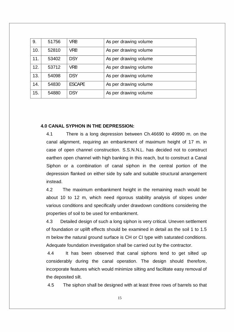
4.0 Canal syphon in the depression 15
5.0 Geo-Technical Data 17
6.0 Borrow Area (BA) 17
Chapter – 4
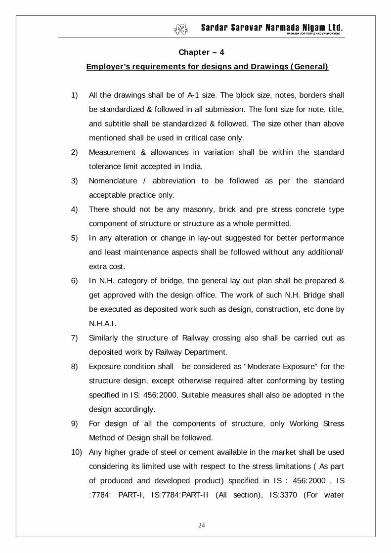
Employer’s requirements for designs and Drawings (General)
1.0 Employer’s requirements for designs and Drawings (General)
24
Chapter – 5
Employer’s requirements for DESIGN
1.0 Employer’s requirements for designs 31
Chapter – 6
Employer’s requirements for submittals by the Contractor
1.0 Employer’s requirements for submittals by the Contractor
44
Chapter – 7
Data for Canal Structures
STRUCTURE DATA FOR THE PROPOSED STRUCTURE ACROSS THE BRANCH CANAL.
1.0 Details of the structure 47
Part-I General Description 48
Part-II Canal Data 49
Part-III Drain Data 54
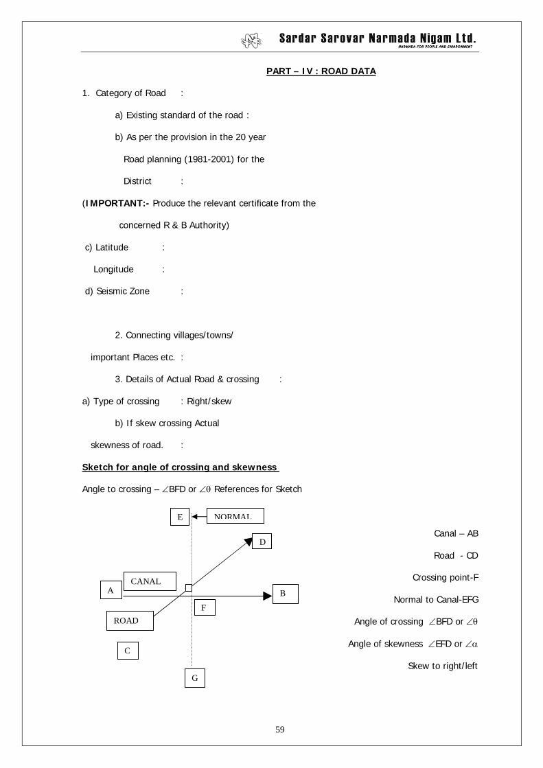
Part-IV Road Data 59
Part-V Soil Data 63
Part-VI Plans / Documents 69
Paragraph No.
Particulars Page no.
1 2 3
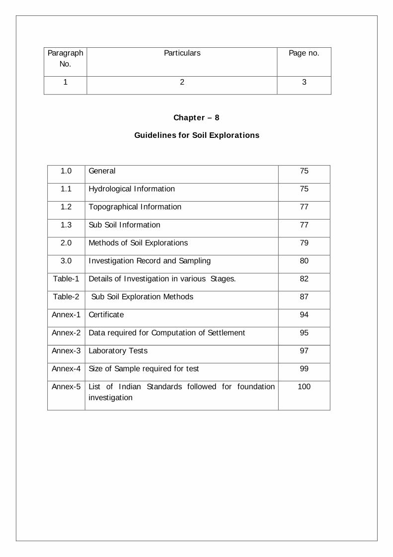
Chapter – 8
Guidelines for Soil Explorations
1.0 General 75
1.1 Hydrological Information 75
1.2 Topographical Information 77
1.3 Sub Soil Information 77
2.0 Methods of Soil Explorations 79
3.0 Investigation Record and Sampling 80
Table-1 Details of Investigation in various Stages. 82
Table-2 Sub Soil Exploration Methods 87
Annex-1 Certificate 94
Annex-2 Data required for Computation of Settlement 95
Annex-3 Laboratory Tests 97
Annex-4 Size of Sample required for test 99
Annex-5 List of Indian Standards followed for foundation investigation
100
Chapter – 9
Criteria for Soil Investigation for canal and canal structures
CANAL STRUCTURES
1.0 Preamble 103
2.0 Order 103
Chapter – 10
Employer’s requirement with reference to the details to be covered up in specific drawings for canal structures
1 List of Drawings of DSY 111
2 List of Drawings of CSY 112
3 List of Drawings of VRB/UVRB/MDRB/SHRB (Deck slab Type)
113
4 List of Drawings of VRB/UVRB/MDRB/SHRB (Box Culvert Type)
114
5 List of Drawings of HR (Single pipe) 115
6 List of Drawings of HR (Double pipe) 116
7 For Open Type Escape (Radial Gate) 117
8 For Open Type Escape (Vertical Gate) 118
9 List of Drawings of CR (Radial) 119
10 List of Drawings of CR (Vertical) 120
11 List of Drawings of CR/Fall (Radial) 121
12 List of Drawings of CR/Fall (Vertical) 122
13 List of Drawings of CR/CSY 123
14 List of Drawings of CR(Radial)/VRB 124
15 List of Drawings of CR(Vertical)/VRB 125
16 List of Drawings for Super Passage 126
Paragraph No.
Particulars Page no.
1 2 3
Chapter – 11
Employer’s guidelines for detailed designs
1 Guidelines for design of Canal sections of Narmada Main Canal
128
2 Guide lines for design of Head regulator on Branch canals
177
3 Guidelines for design of Escape on Branch canal 185
4 Guidelines for design of Canal syphon on Branch canal
190
5 Guidelines for design of Drainage syphon/Culvert on Branch canal
216
6 Guidelines for design of Road bridges on Branch canal
233
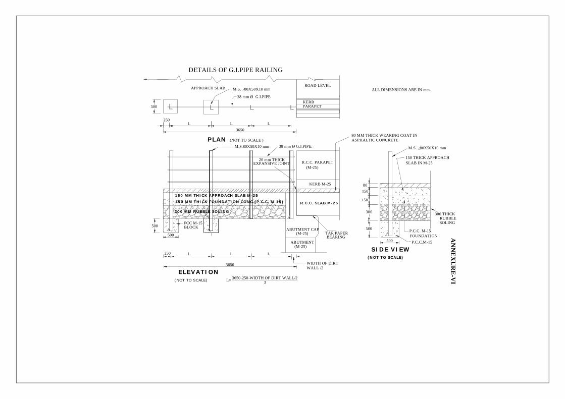
7 Guidelines for design of Super passages on Branch 255
canal
8 Guidelines for design of Cross regulator on Branch canal
274
9 Guidelines for design of Cross regulator/Fall on Branch canal
290
10 Guidelines for Gate design 318
CHAPTER 12
Indicative Quantity Schedules for guidance of the bidder
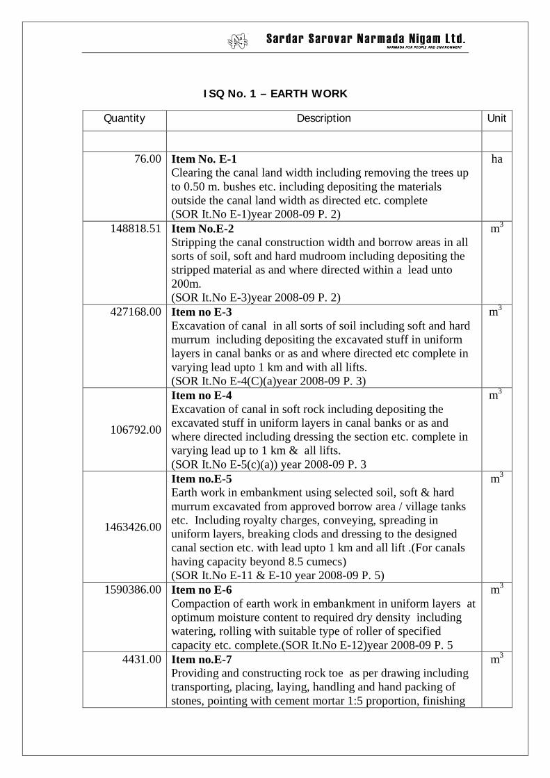
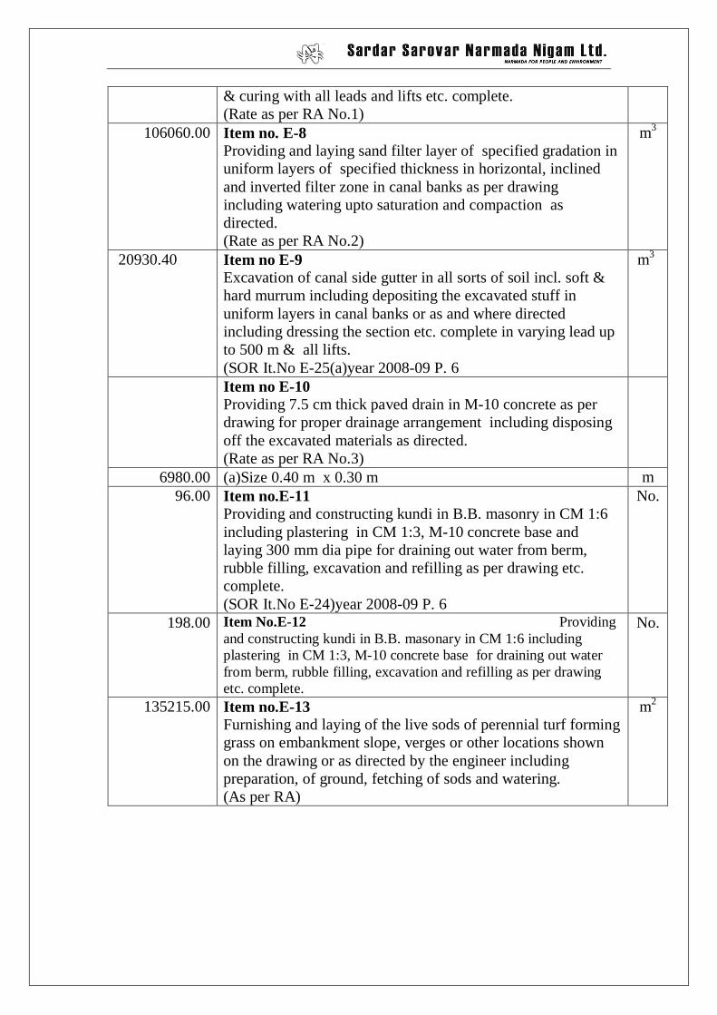
ISQ 1 Earthwork 331
ISQ 2 Lining 333
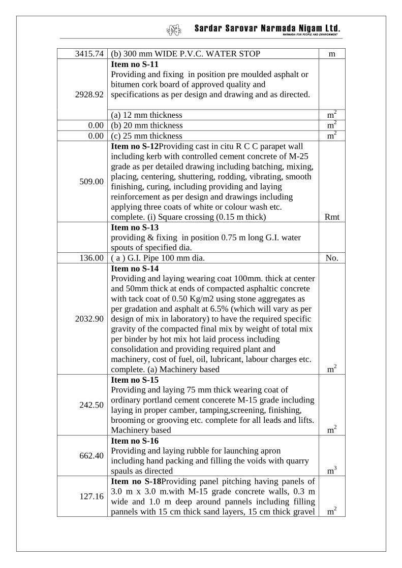
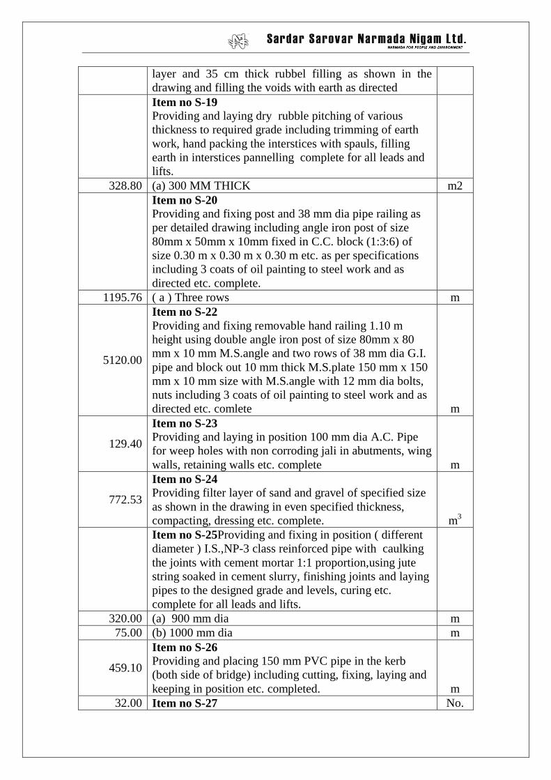
ISQ 3 Structures 335
ISQ 4 Service Road 341
ISQ 5 Gate Works 344
ISQ 6 Control Cabin 349
1
Chapter – 1
Project Description
1. PROJECT BACKGROUND
1.1. The Sardar Sarovar (Narmada) Project is a multipurpose river valley project on the
west flowing river Narmada in Gujarat State located along the west coast of India.
The project is expected to provide irrigation benefits to a gross area of about 3.43
million hectares generate a maximum of 1450 MW i.e. about 950 MW hydro powers
at 60 percent load factor and provide partial flood control. The project is estimated to
cost about Rs. 1,31,806 Million at 1991-92 price level.
1.2. The Project includes 1210 m long and 163 m high concrete gravity darn to store 0.95
M ham water in the reservoir at FRL 138.68 m of which 0.58 M ham will be live
storage. Majority of the Dam work is already completed along with the impounding
reservoir.
1.3. The project also includes two power houses, one river bed power house (6 units of
200 MW each) and the other canal head power house (5 units of 50 MW each)
1.4. Four ponds are created between the main reservoir (Sardar Sarovar) and the head
regulator of the Narmada Main Canal by constructing rock fill dams (dykes) with a
view to provide balancing reservoirs for absorbing i variation in the discharge released
from the canal head power house. These ponds are interconnected by link channels.
1.5. The head regulator for the Main Canal is located at the fringe of the fourth balancing
storage pond.
1.6. The Main canal is one of the largest lined canal in the world having a capacity of 1134
rn (40,000 cusecs) at head and a length of about 460 km up to its tail at Gujarat
Rajasthan border where its capacity will be 71 m (2500 cusecs).
There are 42 branches offtaking from the Main Canal to serve a Gross Command Area
ot 3.43 million hectares (8.472 million acres) and Culturable Command Area of 2.12
2
Million hectares (5.236 million acres). The distribution system will involve construction
of 2500 km of branch canals and about 76,000 km. of distributaries, minors and sub
minors.
1.7. The climate in the project area is tropical with temperature ranging between 9 degree
C. and 45 degree C. The seasons in this region can broadly be classified as:
(i) Rainy season from middle of June to September with total annual rainfall
ranging from 500 mm to 600 mm (about 90 percent of the annual rainfall
occurs in this season)
(ii) Dry season from October to middle of June covering winter and summer.
1.8. The Saurashtra Branch Canal passes through the Kadi Taluka of Mehsana District,
Viramgam taluka of Ahmedabad district and Lakhtar, Patdi andWadhwan taluka of
Surendranagar District. The area of the alignment is of saline one. The salinity exists
in sub-soil and sub-soil water.
1.9. DETAILS OF KBC.
1.9.1. General:
Off-takes from : NMC ch. 384.814 Km. Village – Salimgadh, Ta. – Kankrej,
List of Bench Marks for Kachchh Branch Canal from 45 Km. to 54.90 Km.
Sl. No. TBM/BM NO. DESCRIPTION R.L. in m
above msl
1 BM-92 Located on the pucca floor infront of Jai Mathadi Temple, Devapur village, 204m left side of center line of KBC, at Ch.40110m
19.860
2 STN-12 / BM On top of square stone pillar on the edge of cart track, 261m right side of center line of KBC at Ch.46408m.
22.108
3 BM-92A On top of square stone pillar on the field boundary corner, 22m right side of the center line of KBC at Ch. 46613m and right side edge of cart track to Jhejham village.
20.597
4 BM-93 Located on left abutment of pipe culvert Jhejham - Fangli road.
18.037
5 BM-94 Located on top of fifth concrete guard pillar of causeway towards Jhejham , right side of Jhejham to Fangli road.
8.886
6 STN-14 / BM-95 Located on left abutment of pipe culvert Jhejham - Fangli road.
11.694
7 STN-15 / BM On top of square stone pillar, 47m right side of center line of KBC at Ch.50222m.
20.011
8 BM-96 Located on ringwell concrete plateform under Khejada tree opposite to Radhaswami School on the outskirts of Fangli village.
23.844
9 STN-17 / BM-97 On top of sqaure stone pillar at high ground, 177m rightside of the center line of KBC at Ch. 52059m.
29.603
10 AP-17/ BM On top of square stone pillar of AP-17 of KBC. 21.938
11 BM-98 On top of square stone pillar at 12m left side of center line of KBC at Ch. 53267m.
21.763
12 STN-19 / BM On top of square stone pillar, 8.6m right side of center line of KBC at Ch. 54640m.
22.294
13 STN-20 / BM On top of square stone pillar located at field boundary corner, 102m right side of KBC at Ch.55692m and 8m left side of Fangli-Patanka road.
21.389
14 BM-99 On the pucca floor of the Hanuman temple near the front wall, one feet from the right side corner of the temple, Patanka village.
20.750
15 BM-100 Located on left abutment of pipe culvert WBM road Patanka to Babra at 35m towards Patanka from the T-junction of kacha road to Aluvas.
21.577
16 STN-22 / BM On top of square stone pillar at centrline of KBC at Ch.57230m.
22.795
20
Note:-The contractor shall take and connect the levels with double leveling from nearest Permanent Bench Mark (PBM) and verify the above values and get approved from the EIC before commencing the construction work .The contractor shall fix Temporary Bench Mark (TBM) along the length of the canal at a minimum centre to centre distance of one (10) km.
17 STN-23 / BM On top of square stone pillar, right edge of cart track Babar to Patanka 27m rightside of center line of KBC at Ch. 58225m.
22.389
18 STN-24 / BM On top of square stone pillar at centrline of KBC at Ch.59175m.
23.995
19 STN-25 / BM On top of square stone pillar, 97m left side of center line of KBC at Ch.59212m.
24.322
20 STN-26 / BM On top of square stone pillar, left side of center line of KBC, 115m from AP-22, near KBC Ch.60250m.
23.634
21
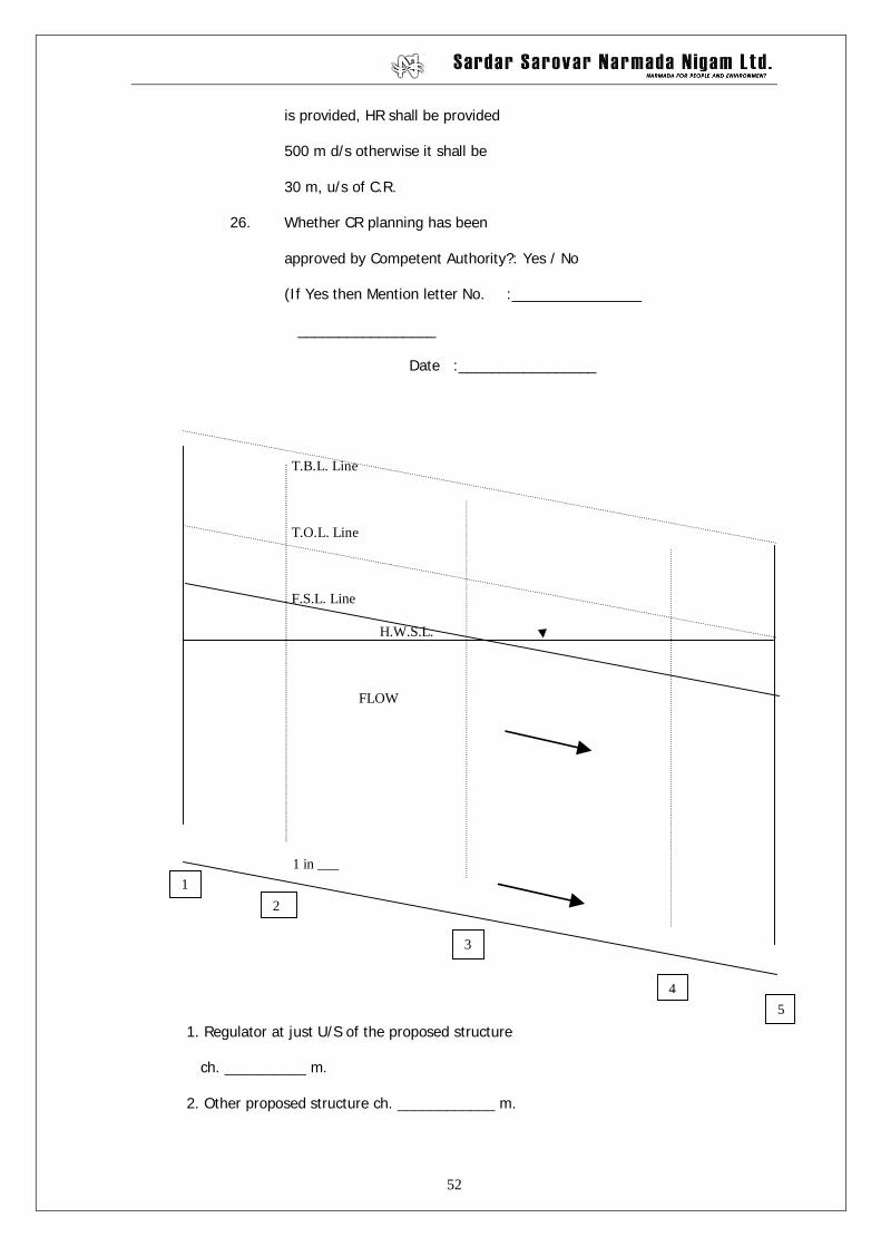
Note:- The FSL Statement will change in the U/S of the canal syphon depending upon the design of canal syphon and head loss allowed through it.
Annexure-3 Full Supply Level & Structure Detail statement of Kuchchh Branch Canal From Ch. 45000 m to 60000 m
Sl. Reach in Metres Ground
Name of Structure Struture Length Total Head Loss (in m) Total
Loss CBL FSL HWSL TOL TBL
No. From To Level Type in m Due to U/S D/S U/S D/S U/S D/S U/S D/S m Grade Structure Section m m m m m m m m m 1 2 3 4 5 6 7 8 9 10 11 12 13 14 15 16 17 18 19 20 45000 - 18.510 24.310 24.483 24.983 25.283
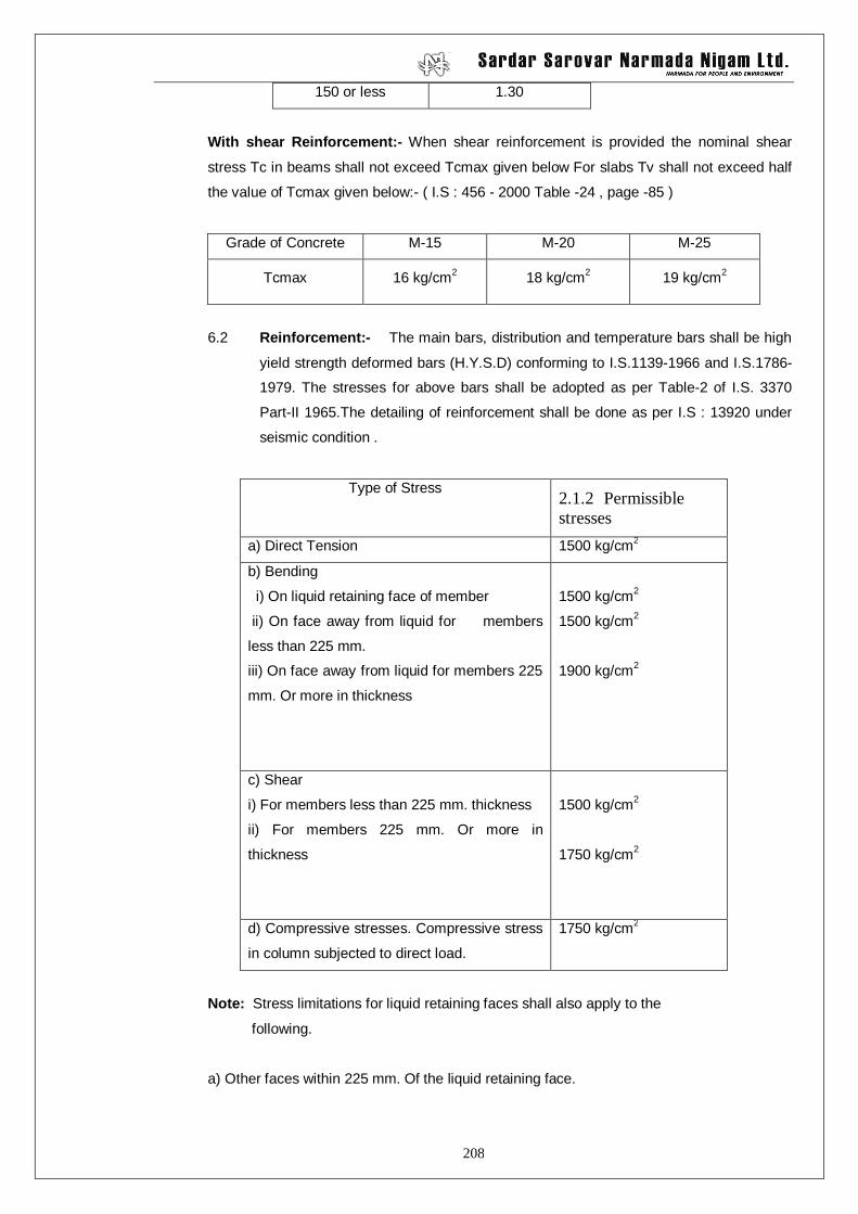
11. Influence factor for immediate settlement (I) kg/sq.m.
12. Poisson’s ratio.
(III) If in case of SM / ML / SP etc. type soil met with at foundation, the
following values shall be furnished.
1. Particle size distribution curve i.e. S-curve.
2. Relative density.
3. Uniformity coefficient (Cu).
(IV) R O C K :
a) If the rock is met with mention
details with log sheet of bore hole
whethered or unwhethered :
1. Hard Rock or Soft Rock :
2. Weathered or Solid :
b) Safe Bearing Capacity (SBC) :
65
(V) S O I L :
(a) Safe bearing capacity of soil (SBC) : ________ t/sq.m.
Details of Trial Pit / bore hole No.____ at
Ch.________ m. On _______________ Branch canal.
SKETCH
Soil parameters as stated above for the structure shall be taken. SBC calculations in accordance
with the I.S. 6403 – 1981 or its latest version shall be furnished.
Note:-
1. In case of high banking, C, value of the earth fill material shall be given.
2. In case bore hole is taken, geological logging of bore hole should be furnished.
3. Position of pre monsoon and post monsoon Ground water table (GWT) RL and its depth below GL
(Mention the year and month when the data was taken).
: prepared by :
Dy.Ex.Engineer Executive Engineer
Sub Division Division
: Checked by :
Dy.Ex.Engineer Executive Engineer
Planning & Design Dn. Planning & Design Division
66
: C E R T I F I C A T E :
Certificate regarding verification of Ground profile for C.D. works at
Ch._________ m. of _______________ branch canal.
Certified that I have visited the site and inspected the strata of the trial pit
and compared it with trial pit register and found correct.
Dy.Ex.Engineer Executive Engine
67
: C E R T I F I C A T E :
Certificate regarding ground water table of nearby well for C.D. work of
Ch. ________ m. of ___________ branch canal.
Certified that I have inspected the nearby well and found ground water at
____________ m. below from G.L. on dated ____________.
Dy.Ex.Engineer. Executive Engineer
68
:CERTIFICATE:
This is to certify that, I have walked over the boundary of the catchment
area for structure at ch. _________ m. of _______________ Branch Canal and
visualised the specific inlets and outlets of nallas or small drains draining in the
catchment area. The same catchment area is marked on S.O.I. Map and verified
by me personally and found as _______ sq.km. and correct to the best of my
knowledge.
Deputy Executive Engineer
Counter signed
Executive Engineer
69
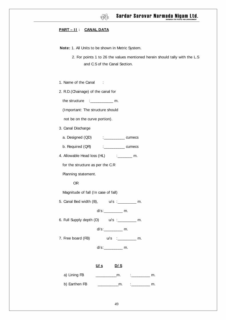
PART-VI : PLANS/DOCUMENTS
1) Index Plan (Scale 1 cm = 500 m.)showing
a) exact location of structure
i) Latitude :
ii) Longitude :
b) Important town/Taluka H.Q/village :
c) Existing roads & railways, in
different colours, 20 year road
planning of the surrounding region
category wise in different columns :
d) Proposed alignment of branch canal/
distributary, location,drainage
etc. :
e) Important rivers/streams :
f) G.T.S.Bench mark (with R.L) :
2) Village Plan (Scale 1 cm = 39.40 m.)
a) Alignment of proposed branch
canal, distributaries chainage
may be shown, location of
proposed structure, drain etc.
(in red colour) :
b) Mark (along with nomenclature)
70
river/drainage/reservoir/tanks
with blue colour, direction of
flow may be shown. :
c) Existing and proposed road
alignment (with 20 year planning,
lanes etc.) wearing surface and
status of road in standard R & B
notations. :
d) Angle of skew for drainage,if
provided. In case of skew
crossing, if proposed to be
made square, show proposed
layout of approaches. :
e) Contours in 1 m. interval
extending upto 1000 m. on either
side of the proposed structure :
f) Details of nearby road and railways
showing location of drainage
structure level crossing canals of
other project etc.
3) SOI Contour Plan (Scale 1 cm = 150 m.)
a) Alignment of proposed branch
canal/distributary with chainage
and location of the proposed
71
structure and details as for
village map.
b) HFL Line :
c) Direction of flow :
d) Angle of skew, if provided :
e) Contour beyond HFL and upto 200 m
on either side :
f) Catchment area boundary (With
Catchment boundaries of adjacent
Drainage structures in U/S and
D/S of the proposed structure. :
(g) Contour line at 0.5 m. interval.
4) Longitudinal Section (Scale 1 cm = 30 m. H)
(Scale 1 cm = 1 m. V)
a) Part L/S of Canal (1000 m. on
either side of structure) with
details of CBL,FSL, TBL etc. :
Note:-
Show on plan alignment of branch/dist. alignment of Drain/Road, Curve, distance
from the curve (Generally avoid structure falling within curve)
b) L/S of Nalla (Scale 1 cm = 30 m. H)
(Scale 1 cm = 1 m. V)
i) 300 m. on u/s side 500 m. on
d/s side of the structure :
72
ii) For flat topography 500 m. on
u/s side and 1000 m. on d/s side :
iii) 1000 m. either side for large
structure having C.A more
than 25 sq.km. :
iv) H.F.L Line
c) Details of trail pits upto 2.0 m.
below Nalla bed level with R.L.
and ground water level :
5) Cross Section (Br.Canal/Dist.) (Scale 1 cm = 100 cm.)
a) C/S of canal at structure
site showing canal section
service road, Inspection path,
plantation width spoil bank,
borrow pits, drain etc. :
b) C/S of existing river/Nalla
up to Ridge portion. (Scale 1 cm = 30 m. H)
(Scale 1 cm = 1 m. V)
i) At every 10 m. upto 150 m.
on u/s. :
ii) At every 10 m. upto 240 m.
on d/s :
6) C.R.Planning Statement :
7) S.B.C.calculation :
73
Note:-
1) Levels at sufficient points on the c/s shall be
taken to truly represent the shape of the
Nalla/drain/stream.
2) The c/s should not be drawn to distorted scale,
preferably 1:4 scale shall be adopted.
: Prepared by :
Dy.Ex.Engineer Executive Engineer
Sub Division Division
: Checked by :
Dy.Ex.Engineer Executive Engineer
Planning & Design Dn. Planning & Design Dn.
74
SKETCH SHOWING LOCATION OF TRIAL BORE / TRIAL PITS
Location of bore hole for structure ____________ m. at Ch.
_____________m.
River flow
U/S CANAL FLOW BH-L1 BH-C BH-R1
D/S
75
Chapter – 8
Guidelines for Soil Explorations
Guide lines on Investigation for structures on Branch Canals of Narmada Canal
System.
1.0 General
A detailed investigation of the site is essential to design a safe and economical
structure on realistic basis. The object of site investigation is to provide the
designer with informations about the existing conditions viz. Hydrological,
topographical and sub soil information as detailed below:-
1.1. Hydrological Information
1.1.1 Catchment Area:- Catchment area shall be marked on Toposheet as
well as on S.O.I. map covering catchments of adjoining streams with flow
direction, roads and railway structures with sill level, H.F.L. of structure, road
formation etc. It is desired that field officer should walk over the boundary of
catchment area and visualize the specific inlets and outlets of the nallas or small
drains draining in the catchment and it should be clearly shown on the map so
that correct discharge coming from the catchment can be derived. It shall also be
observed that back water or spill in water of any near by river is entering in the
catchment of the C.D. works under observation or not. Length of the longest
stream shall be carefully marked on the S.O.I. along the stream up to the
farthest point. For arriving at the correct slope of drain, levels shall be given for
atleast 3 to 5 points with corresponding length. A certificate regarding verification
of catchment area shall be given by field officer as per Annex.1.
1.1.2 Estimation of Design Flood:- For checking the overall safety of the
structure, from foundation, scour and free board considerations, the following
flood shall be adopted.
Sr.
No.
Catchment Area in
sq.km.
Method Remarks.
76
1 Less than 25.00 As per bridges and floods wing
report no.RBF-16 method.
2 25.00 to 518.00 Flood Estimation Reports of
various sub zones published
by the Director (Hydrology for
small catchment) C.W.C., New
Delhi
For Sub Zone
3(a), or 3(b) as
the case may be.
3 Above 518.00 Each case shall be taken up
specifically and decided after
detailed examination as
mentioned in IS 7784, Part-I,
1993
As per IS 7784 (Part-I), 1993 frequency of design flood for cross drainage
structures are tabulated as below:-
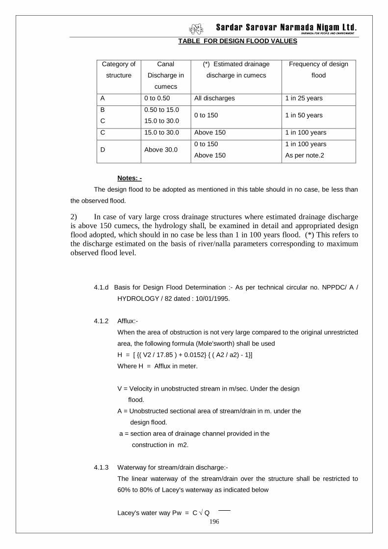
Design Flood Values.
Category
of
structure
Canal discharge in
m3/ sec.
(*) Estimated
drainage discharge in
m3/sec.
Frequency of Design
flood.
A 0.00 to 0.50 All discharges 1 in 25 years
B 0.5 to 15.00 0.00 to 150.00 1 in 50 years
C 15.00 to 30.00 Above 150.00 1 in 100 years
D Above 30.00 0.00 to 150.00
Above 150.00
1 in 100 years
As per Note-2
Notes:-1) The design flood to be adopted as mentioned in this table should in
no case be less than observed flood.
2) In case of very large cross drainage structures where estimated
drainage discharge is above 150.00 cumecs, the hydrology shall be
examined in detail and appropriate design flood adopted, which
77
should in no case be less than 1
in 100 years.
(*) This refers to the discharge estimated on the basis of river/ nalla
parameters corresponding to maximum observe flood level.
1.1.3 Determining the observed flood:- For determining observed flood, the
field officer should go to the site more than twice in a year immediately after the
floods occur and observe the levels carefully. The value of “N” (Co-efficient of
rougosity) shall be adopted carefully and the correct observed discharge may be
determined. Local inquiry is necessary to obtain the highest flood level and
thereby to calculate the maximum observed flood.
1.1.4. L.S and C/S of drain:- For large drains having C.F. more than 25 sq.km.
L.S. and C.S. of drain shall be given 1000 mt. on either side of the structure. For
small drain L.S. and C.S. may be given for 300 mt. on either side of structure.
But in case of drainage syphon for small drain L.S. of drain shall be given 500 mt.
in u/s and 1000 mt. in d/s of the structure.
1.2. Topographical Information:- Index map shall be given showing the
exact location of structure with latitude and longitude. Nature of the catchment
area i.e. whether it is plain, hilly or undulating etc. with type of catchment that
whether it is fan shaped, leaf shaped etc. shall be given. Flood retention period
and hazards occurred due to this flood retention shall be given. Details of the
influence of the flood on the sanitation of the local people shall also be given.
Type of average soil on surface in the catchment area shall be given, so
that correct flood calculation can be done.
1.3 Sub soil information:- The sub soil information is to provide safe and
secure foundation to take the estimated load without shear failure and undue
settlement. The foundation investigation shall be carried out below the
foundation grade. For shear failure the engineering properties of soil shall be
given.
78
In many cases the soil below the foundation level deep strata of “CH”, highly
plastic clay, with high moisture content meets with. The soil may consolidate
under the applied load resulting into settlement over a quite long time. This may
damage the structure. For such cases consolidation times has to be reduced by
taking suitable measures. It is therefore emphasized that for such cases
undisturbed samples may be collected and tested very scrupulously.
Where MH/MI/ML type of soil is met with in foundation, the liquefaction potential
shall be studied.
A list of data required for “CH” type of soil is given in Annex-II.
Due to the complexity of natural deposits the sub soil investigation is discussed in
the following paragraphs. The sub surface explorations are generally carried out
in stages namely, (1) Reconnaissance, (2) Preliminary and (3) Detailed as given
below:
1.3.1. Site Reconnaissance:- This helps to assess the need for preliminary for
detailed investigations It includes a study of local topography, excavations,
ravines, evidence of erosion or landslides, water level in streams, water courses
and walls, flood marks, drainage pattern, location of seeps etc. The information
on some of these may be obtained from topographical maps, geological maps,
soil survey maps and arial photographs.
1.3.2. Preliminary Exploration:- The scope of this exploration is restricted to
the determination of depth, thickness, extent and composition of each soil
stratum, location of rock and ground water and also to obtain approximate
information regarding strength and compressibility of the various strata.
1.3.3. Detailed Exploration:- The detailed investigation follow preliminary
investigation and should be planned on the basis of data obtained during
79
reconnaissance and preliminary investigation. The scope of this exploration is
restricted to the determination of engineering properties of sub soil viz. shear
strength, density, natural moisture content, permeability etc. The detailed
investigation includes boring and detailed sampling to determine these
properties. All in-situ tests are to be supplemented by laboratory investigations.
The guide lines for above stage investigation is given in Table-1, which shall be
followed in normal circumstances and shall be followed with caution and in the
spirit of the requirement of relevant I.S .Codes and technical publications.
2.0 Methods of Sub Soil Exploration:-
The methods of sub soil explorations are given in Table-2. However, the
foundation investigation procedure to be followed in general is give below for
guidance.
2.1. Soil Strata:- The soil below foundation level shall be tested with standard
penetration tests and/or by collecting undisturbed samples and test for
engineering properties. The water table shall also be recorded. In case of
cohesion less soil, where collecting undisturbed samples is not possible only S.P.
Tests shall be carried out. The S.P. Tests and collection of undisturbed samples
shall be done as below. Consolidation tests shall be carried out where highly
plastic clays viz.CH, CL, MH, MI is met with.
Sr.No. Item Depth.
1 Undisturbed samples 45 cm.
2 S.P. Tests scaling drive 15 cm.
3 S.P. Tests 15 cm.
4 S.P. Tests 15 cm.
To be continued to final depth in this order.
2.2. Rocky Strata:- In case the rocky strata is met with below the
foundations, the bore hole using rotary drilling machine and core bit having NX
80
size bit shall be drilled. During drilling care shall be taken to obtain maximum
core recovery. In case rock is highly weathered or rock is such that the
cementing material shall be removed during drilling and core recovery obtained is
less, double tube core barrel or triple tube core barrel shall be used.
The drilling at a stretch shall be done for maximum 1.5 m. depth or
change of strata whichever is earlier. The drilling time, wash water, water table
artesian condition met with if any, shall be recorded in drilling register.
The logging by Geologist shall be done and submitted along with report
and recommendation of Geologist to use the rock as foundation of particular
structure.
3.0 Investigation record and sampling:-
3.1 The soil strata can be examined in trial pits, the trial pits should therefore
be preferred to auger holes/bore holes. After the trial pit excavation is
completed or during the excavation logging of the pits should be done and field
classification of the soil should be carried out as outlined in IS 1498-1970.
3.2 In bore hole all the information viz. water table level, rate of drilling wash
water details, water loss during drilling and any other useful information shall be
recorded in drilling/investigation register.
3.3 The undisturbed samples shall be collected in the form of chunk samples
from trial pits and Shelby tube samples from bore holes. The samples shall be
protected properly during storing and their transportation to laboratory. The
testing shall be carried out as early as possible, to get reliable results.
3.4 In rock, the cores obtained shall be preserved in core boxes with proper
identification marks of location of hole and depth from which cores are
recovered. The cores shall be kept in core box as they are recovered from the
core barrel.
Testing:- Laboratory testing of all soils samples shall be carried out as detailed
81
in Para 1.3. For rock the bore hole log shall be prepared by the Geologist and
foundation grade and SBC shall be given.
Record of investigation data :- The results of laboratory test as per Para 1.3
and bore hold log as per Para 3.3. shall be furnished to the design office.
82
Table-1
Table-1 showing details of investigation in various stages (Please refer Para -5)
Sr.
No.
Stage Choice of Methods Spacing Location Depth of Exploration Remarks.
1. Reconnaissance
stage
Visual observation of
topography, cut-crops,
erosional features, quarries,
excavation, landslides,
water level in streams and
water courses, flood marks,
drainage pattern, location
seeps etc. Ground water
may be observed in existing
wells.
- - - 1) The investigation
should cover a
considerable
distance from the
structure based on
topography and
alternative sides.
2) The appraisal
should define major
advantages, defects
of the foundation
and material
deposits at
alternative sites with
reasonable
83
certainty.
3) The data for
overburden may be
obtained by visual
observation and
field identification
tests.
84
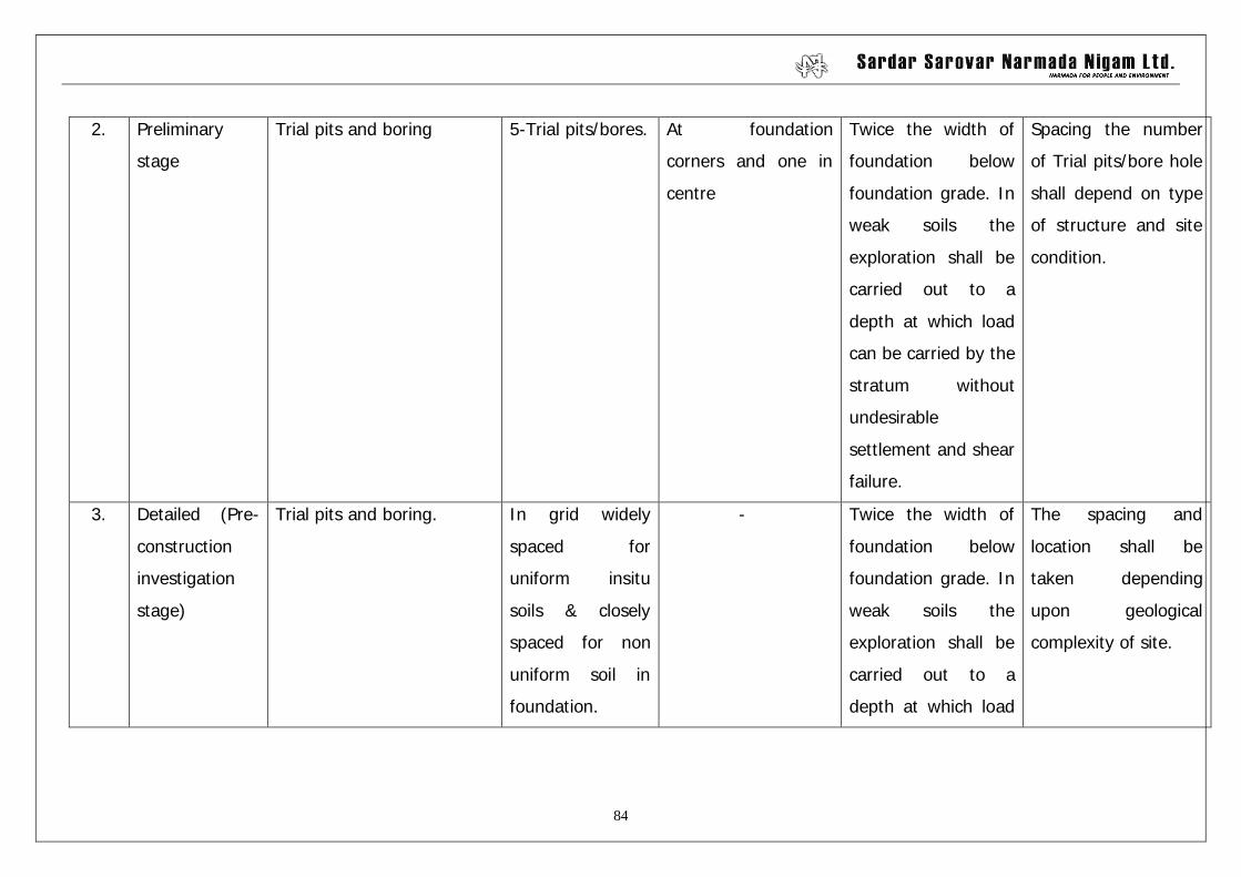
2. Preliminary
stage
Trial pits and boring 5-Trial pits/bores. At foundation
corners and one in
centre
Twice the width of
foundation below
foundation grade. In
weak soils the
exploration shall be
carried out to a
depth at which load
can be carried by the
stratum without
undesirable
settlement and shear
failure.
Spacing the number
of Trial pits/bore hole
shall depend on type
of structure and site
condition.
3. Detailed (Pre-
construction
investigation
stage)
Trial pits and boring. In grid widely
spaced for
uniform insitu
soils & closely
spaced for non
uniform soil in
foundation.
- Twice the width of
foundation below
foundation grade. In
weak soils the
exploration shall be
carried out to a
depth at which load
The spacing and
location shall be
taken depending
upon geological
complexity of site.
85
can be carried by the
stratum without
undesirable
settlement and shear
failure.
86
4. Construction
stage
As dictated by Geological
complexities.
- - - Construction stage
exploration should
aim at making
available duty for
(1) The evaluation
of specific
foundation
features and
(2) Preparation of
foundation
grade maps to
guide
foundation
preparation &
treatment.
NOTE:- The foundation investigation shall be carried out below foundation grade.
87
Table-2
Sub Soil Exploration Methods:-
Sr.
No.
Method Description Applicability.
1) Aerial
Photography
- For intensive investigation in
accessible area serial
photography is not essential
for soil exploration. For in
accessible and unfamiliar
areas air photography may be
adopted as an aid in planning
for detailed exploration work.
2) Geophysical
Methods
They are grouped as a)Seismic,
b) electrical, c) Magnetic, d)
Gravitational & e) Sonic.
a) Seismic Method Shock of seismic waves are
created by detonating small
charges or by striking a rod or
a plate near the surface. The
radiating waves are picked up
and time of travel from source
recorded by detectors known
as geophones or seismometers.
In seismic method, either
refracted or reflected waves
are detected.
i) Refraction
Method
In this method, time of arrival
of waves refracted at interfaces
between different strata are
recoded.
Used to determine depth to
rock or depths of significantly
differing soil strata. Can be
used only when velocity of
travel in lower layers is
88
significantly greater than the
upper ones. This method is
usually limited to depths up to
30 m. in a single stratum.
ii) Reflection
Method
Here seismometers record the
travel time of seismic waves
reflected from interface
between adjoining strata.
This method is usually adopted
to determine depth of deep
bed rocks. Generally applied
for depths exceeding 600 m.
At present this method is
mainly used in off-shore
investigation.
iii) Velocity
sounding
methods
In this method, seismic waves
are generated. Their travel
times & hence travel velocities
in travelling through soil along
the hole in down or up
direction or across the holes
are determined.
These method are used for
determining dynamic elastic &
shear modulus which enable
to estimate coefficient of
elastic uniform compression
etc.
b) Electrical
resistivity
method
In this method four metallic
spikes to serve as electrodes
are driven into the ground at
equal intervals along a line. A
known potential is then applied
between the outermost
electrodes and potential drop is
measured between the
innermost electrodes. Flow of
electric current is also
measured. This enables to
estimate resistivity of stratum.
From known resistivity of
Used to determine vertical as
well as horizontal extent of soil
strata at foundation site for
larger structures, such as
dams, Depth of exploration is
generally limited to about 30
m. Also used to obtain data for
designing electrical grounding
system.
89
different strata, prediction can
be made about the nature of
the stratum.
c) Magnetic
Method
- Rarely used in Civil
Engineering works.
d) Gravitational
Method
Rarely used in Civil
Engineering works
e) Sonic Method In this method time of travel of
sound was reflected from
certain boundaries between
different strata are measured.
From the knowledge of velocity
of sound wave a different
strata, depth to strata can be
obtained.
Used to determine position of
mud line and depth to hard
stratum underlying mud. Use
is currently limited to shallow
depths.
3) Test Pits,
Trenches and
Open Cuts.
Tests pits, trench or any other
type of open excavation an be
carried out manually or by
machines The sides of open
cut, need be provided with
lateral support with the help of
bracings whenever there is a
danger of cave-in.
Applicable in all soils provided
for visual examination of soil
strata in their natural
conditions. Disturbed or
undisturbed samples can be
conveniently obtained at
required depths. Use is usually
limited to shallow depth of 0
to 5 m. For greater depths
cost of open excavation and
necessary side bracing
becomes uneconomical
4 Borings Principal boring types are
auger boring, wash boring,
percussion drilling and rotary
drilling.
Refer respective type of
boring.
90
a) Auger boring Bore hole is advanced by hand
or power operated auger with
periodic removal of material. In
some cases continuous auger
may be used requiring only one
removal. Casing is generally
not used with auger boring.
Hand augers are used in soft
to stiff cohesive soils, in sandy
solty soils have water table
with hand auger, depth is
usually limited to 6 m. Power
driven augers can be used to
great depth, even to 30 m.
and used in almost all type of
soils above water table. This
method provides almost
continuous disturbed samples,
Undisturbed samples can be
obtained at required depths by
using proper samplers.
b) Wash promg. Bore hole is advanced by
chopping, twisting action of a
light chopping bit and jetting
action of a drilling fluid, usually
water, under pressure.
Changes in soil strata are
indicated by changes in the
rate of progress of boring
examination of outcoming
slurry and cuttings in the
slurry. Casings are used
whenever necessary to prevent
cave-ins.
Can be used in all types of
soils except those containing
bounders, can be used to
great depths, adopted easily at
inaccessible. Samples obtained
are in highly disturbed and
slurry form, undisturbed
samples whenever needed can
be obtained by use of proper
samplers.
c) Percussion
drilling
Bore hole is advanced by
chopping action of heavy bit
driven by power. Water is
added at the bottom of bore
hold during chopping action, if
Can be used in all soil types
including soils containing
boulders. Can be used for
great depths. Use is limited
because of difficulty in
91
the ground water is not already
struck. Slurry formed at bottom
of bore hole is removed by
bailer or sand pump. Casing is
generally required. Changes in
strata are predicted from the
rate of progress of boring and
examination of slurry bailed
out.
determining strata changes as
chopping action can cause
considerable disturbance and
because of high cost. May be
used in combination with
auger or wash borings when
boulders are encountered.
Undisturbed samples
whenever needed can be
obtained by use of proper
samples.
d) Rotary drilling Bore holes is advanced by
power rotation of drilling bit
and removal of cuttings by
circulating fluids which may be
water bentonite slurry or mud
slurry. Whenever rock or
boulders are encountered
suitable bits viz. diamond
studded bits or tun gesten
carbide bits or steel bits with
shots are to be used for
drilling. Casing may or may not
be needed during drilling.
Changes in strata are indicated
by change in rate of advancing
of bore hole ,action of drilling
tools, examination of cuttings
in drilling fluid.
Can be used in all types of
soils and rocks, can be used to
great depths, being
increasingly used because of
fast rate of progress in all soil
types, but difficult to use at
increasable locations because
of heavy machinery.
Undisturbed samples can be
obtained at desired depths by
using suitable samplers.
e) Drive tube
boring
Force open pipe or tube with
sharpened edge, without
rotation, into soils withdraw
Fine grained cohesive and
slightly cohesive soils, such as
loess firm to soft clays and
92
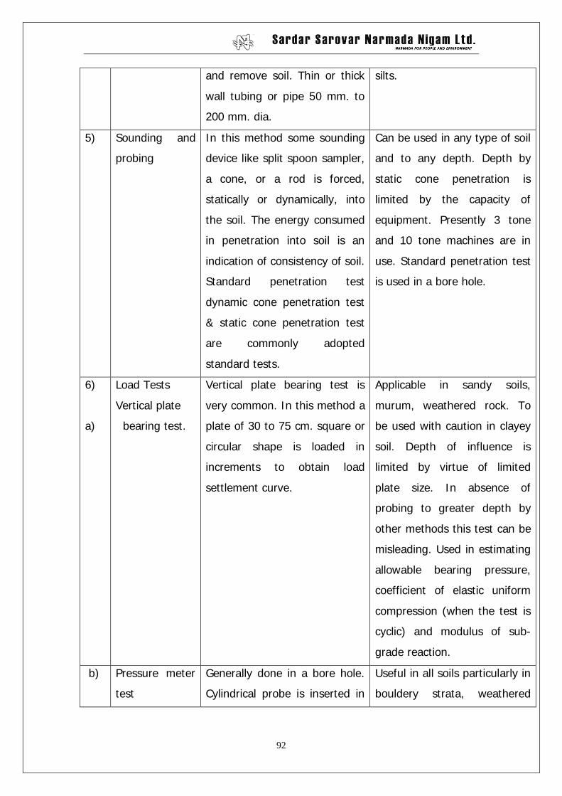
and remove soil. Thin or thick
wall tubing or pipe 50 mm. to
200 mm. dia.
silts.
5) Sounding and
probing
In this method some sounding
device like split spoon sampler,
a cone, or a rod is forced,
statically or dynamically, into
the soil. The energy consumed
in penetration into soil is an
indication of consistency of soil.
Standard penetration test
dynamic cone penetration test
& static cone penetration test
are commonly adopted
standard tests.
Can be used in any type of soil
and to any depth. Depth by
static cone penetration is
limited by the capacity of
equipment. Presently 3 tone
and 10 tone machines are in
use. Standard penetration test
is used in a bore hole.
6)
a)
Load Tests
Vertical plate
bearing test.
Vertical plate bearing test is
very common. In this method a
plate of 30 to 75 cm. square or
circular shape is loaded in
increments to obtain load
settlement curve.
Applicable in sandy soils,
murum, weathered rock. To
be used with caution in clayey
soil. Depth of influence is
limited by virtue of limited
plate size. In absence of
probing to greater depth by
other methods this test can be
misleading. Used in estimating
allowable bearing pressure,
coefficient of elastic uniform
compression (when the test is
cyclic) and modulus of sub-
grade reaction.
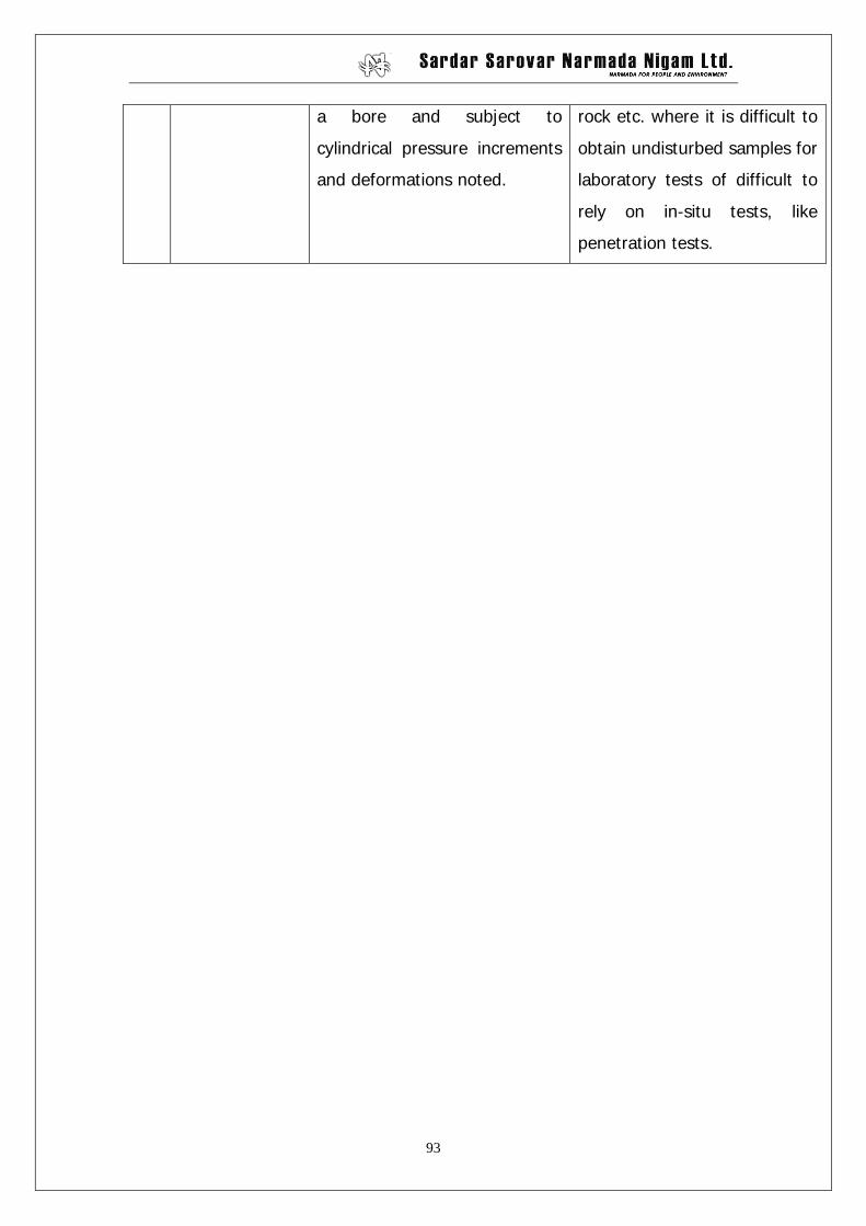
b) Pressure meter
test
Generally done in a bore hole.
Cylindrical probe is inserted in
Useful in all soils particularly in
bouldery strata, weathered
93
a bore and subject to
cylindrical pressure increments
and deformations noted.
rock etc. where it is difficult to
obtain undisturbed samples for
laboratory tests of difficult to
rely on in-situ tests, like
penetration tests.
94
ANNEX – 1.
C E R T I F I C A T E
This is to certify that, I walked over the boundary of catchment
area of cross drainage structure at ____________________m. of
_________________Branch Canal and visualize the specific inlets and outlets
of nallas or small drain, draining in the catchment area. The same catchment
is marked on the S.O.I. map and verified by me personally and found to be
_______________sq.km
Deputy
Executive Engineer
Countersigned.
Executive Engineer.
95
: ANNEX – 2 :
(I) DATA REQUIRED FOR COMPUTATION OF SETTLEMENT.
1. Poison’s ratio : U
2. Modulus of Elasticity : Es (with stress Vs strain curve)
3. Field dry density : rd
4. Water content : w
5. Preconsolidation Pressure : Pc
6. e log P curve :
7. Compression Index : Cc
8. Specific gravity : G
9. Coefficient of volume change : mv
10. Coefficient of compressibility : av
11. Initial void ratio : eo
12. Co-efficient of consolidation
-in vertical direction
-in radial direction
:
:
Cvz
Cvr
13. Coefficient of permeability : In horizontal dir. : kh
In vertical dir: kv
14. At curve for 90% consolidation: :
15. Liquid limit L.L. : Plastic limit – PL
Plasticity Index - IP
16. IS classification :
17. Grain size distribution : S Curve:
18. Ground Water level : WT
19. Degree of saturation : Str.
20. Saturated density : rsat
21. At least minimum five (5)
consolidation tests and two (2)
triaxial tests for each bore hole
96
below foundation level for clayey
strata.
22. Free swell at foundation level :
23. Swelling Pressure :
24. Water table variation in pre-
monsoon & post monsoon:
:
25. The depth of bore hole should be
the twice the width of structure
below foundation level.
26. Soil profile, Geological cross
section at centre line of canal
(showing above details).
II. DATA REQUIRED FOR COMPUTATION OF S.B.C.
1. Angle of internal friction : Ø By triaxial as well as Box shear
test.
2. Cohesion of soil : C
3. Dry density of soil : rd
4. Water content : w
5. Ground water level :
6. Specific gravity of soil :
7. ‘N’ value for 30 cms. penetration :
8. Unconfined compressive strength : cu
9. Relative density in case of sandy
stata
ID
97
ANNEX – 3
LABORATORY TEST
Sr.
No
Test Equipment Purpose of testing
1 2 3 4
1. Grain size analysis
IS 2720-IV
Coarse sieve (80 mm.
03,37.5, 25.8 20.00, 10.0,
6.3, 4.75 mm). Fine sieve (21
mm 600 micron, 425, 212, 75
micron), balance oven, stirrer,
hydrometer with jars.
For classification of soil
and thereby getting
indication of
2. Plasticity Index
IS 2720-V
Liquid limit device grooving
tools and sieves, oven,
Uppal’s cone penetrometer.
Indicates properties of
soils, Test not possible
for non plastic soils
which are used for
casing.
3. Standard compaction
IS: 2720-VII
Standard compaction mould
with base, collar, and
rammer, soil, extractor
balance 20 kg. oven 212.75
micron, balance oven, stirrer,
hydrometer with jars.
For determining the
maximum density which
can be attained on field
optimum moisture
content, with standard
energy.
4. Relative density
IS 2720-XIV
Relative density apparatus,
vibrator, balance 50 kg. oven.
Similar as above but for
coarse grained soil
5. Field density and
moisture
IS: 2778
XXVII -1974
XXXX-1975
XXXIII - 1971
Core cuter and replacement
kit and water replacement kit.
To determine the
placement density and
monitor compaction
effect. It also indicates
adequacy of moisture
content.
6. Permeability Permeability apparatus soil To decide drainage
98
IS: 2720- XVII-1966 extractor, oven. condition under which
the soil will behave in
field, anticipate probable
seepage and design
drains.
7. Field permeability
IS:5529-1969
Field permeability apparatus
like water storage drum,
shovels, augers etc.
To determine the
drainage condition of soil
insitu.
8. Direct shear
IS: 2720-IV
Direct shear apparatus soil
extractor, balance 5 kg.
To determine shear
strength of soil in
foundation or in
embankment.
9. Consolidation
IS:2720-XV- 1965
Consolidate test apparatus,
oven balance.
To determine settlement
rate and magnitude and
to assess whether soil is
normally consolidated or
preconsolidated.
10. Moisture content
IS: 2720- II - 1973
Balance oven or rapid
moisture meter.
To determine degree of
saturation, consistency
rate of a natural strata
or a compacted fill.
99
ANNEX -4
Size of Sample required for tests.
Sr.
No.
Test Quantity required for soil having maximum particle
size of
4.75 mm 10 mm 20 mm 40 mm 80 mm
1. Particle size analysis 0.40 kg 1.50 kg 6.5 kg 25 kg 60 kg
2. Liquid limit 270gm - - - -
3. Plastic limit
(Passing micron)
50 gm
425
-
425
- - -
4. Shear 3 kg 120 kg 120 kg 120 kg 120 kg
5. Consolidation (Undisturbed
sample)
75 mm
dia.
- - - -
6. Permeability 5 kg 15 kg 30 kg 120 kg 120 kg
7. Proctor
a) Light compaction
20 kg 20 kg 20 kg - -
b) Heavy compaction 20 kg 20 kg 20 kg - -
8. Relative density 12 kg 25 kg 50 kg 100 kg 120 kg
Total for all
Tests:
65 kg 200 kg 250 kg 365 kg 420 kg
100
ANNEX -5
List of Indian Standards Followed for Foundation Investigation.
Sr.
No.
Description IS Code No.
1. Classification and identification of soil for general engineering
purpose
1498 - 1970
2. Methods of tests for soil (Part-I) preparation of dry soil samples
for various tests.
2720 – 1983
(Part-I)
3. Method of tests for soils (Part-II) Determination of water
content.
2720 – 1973
(Part-II)
4. Method of test for soil (Part-IV) grain size analysis 2720 – 1975
(Part-IV)
5. Method of tests for soils (Part-V) Determination of liquid and
plastic limit
2720 – 1985
(Part-V)
6. Method of tests for soils (Part-VI)
Determination of shrinkage factors.
2720 – 1972
(Part-VI)
7. Method of tests for soils (Part-VII) Determination of water
content dry density relation usi9ng light compaction.
2720 – 1980
(Part-VII)
8. Method of tests for soils (Part-VIII) Determination of water
content dry density relation using having compaction
2720 – 1983
(Part – VIII)
9. Methods of tests for soils (Part-IX) Determination of dry density
moisture content relation by constant weight of soil method.
2720-1971
(Part-IX)
10. Methods of tests for soils (part-X) Determination of unconfined
compressive strength
2720 – 1973
(Part-X)
11. Methods of tests for soils (part-XI) Determination of shear
strength parameters of a specimen tested in unconsolidated
undrained triaxial compression without the measurement of
pore pressure.
2720-1971
(Part-XI)
12. Methods of tests for soils (Part-XII) determination of shear
strength parameters of soil from consolidated undrained triaxial
2720 -1981
(Part-XII)
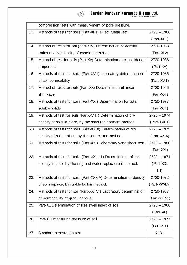
101
compression tests with measurement of pore pressure.
13. Methods of tests for soils (Part-XIII) Direct Shear test. 2720 – 1986
(Part-XIII)
14. Method of tests for soil (part-XIV) Determination of density
Index relative density of cohesionless soils
2720-1983
(Part-XIV)
15. Method of test for soils (Part-XV) Determination of consolidation
properties.
2720-1986
(Part-XV)
16. Methods of tests for soils (Part-XVII) Laboratory determination
of soil permeability
2720-1986
(Part-XVII)
17. Method of tests for soils (Part-XX) Determination of linear
shrinkage
2720-1966
(Part-XXI)
18. Methods of tests for soils (Part-XXI) Determination for total
soluble solids
2720-1977
(Part-XXI)
19. Methods of test for soils (Part-XVIII) Determination of dry
density of soils in place, by the sand replacement method
2720 – 1974
(Part-XVIII)
20 Methods of tests for soils (Part-XXIX) Determination of dry
density of soil in place, by the core cutter method.
2720 – 1975
(Part-XXIX)
21 Methods of tests for soils (Part-XXI) Laboratory vane shear test. 2720 – 1980
(Part-XXI)
22. Methods of tests for soils (Part-XXL III) Determination of the
density implace by the ring and water replacement method.
2720 – 1971
(Part-XXL
III)
23. Methods of tests for soils (Part-XXXIV) Determination of density
of soils inplace, by rubble bullon method.
2720-1972
(Part-XXXLV)
24. Methods of tests for soil (Part-XXI VI) Laboratory determination
of permeability of granular soils.
2720-1987
(Part-XXLVI)
25. Part-XL Determination of free swell index of soil 2720 – 1966
(Part-XL)
26. Part-XLI measuring pressure of soil 2720 – 1977
(Part-XLI)
27. Standard penetration test 2131
102
28. Dynamic cone penetration test 4968 (Part I
& II)
29. Static cone penetration test 4968 (Part-
III)
30 In-situ vane shear test 4434
31 Plate bearing test 1888
32 Pile load test 2911 (Part-
IV)
33 Sand cone method 2720- (Part-
X (VIII)
34 Permeability Test 5529
35 California Bearing Ratio Test 2720 (Part-
XXXI)
36 Dynamic Tests for Dynamic properties of soils 5249
103
Chapter – 9
Criteria for Soil Investigation for canal and canal structures
CANAL STRUCTURES. 1.0 PREAMBLE :
Guide Lines on Investigation for Canal structures on Branch Canals of
Narmada Canal System has been issued by S.E., N.P.P.D.C., Gandhinagar
vide his letter No. NPPDC/H/Guide Lines/Investi-gations/2595 dt. 3.11.1998.
The Guidelines were for the purpose of determination of types of tests to be
carried out at various stages of investigations and were generalized for all
types of structures. Thereafter detailed guidelines incorporating various
aspects like no. of bore holes, their locations , types of tests, etc. keeping in
view the type of structures were published by S.E., N.P.P.D.C., Gandhinagar
vide letter No. NPPDC/B/Soil/Investigation/562 dt. 20.3.2003.
Despite many such efforts to guide the field offices as to how to conduct soil
investigation, lot many lacuna in the ground work have been encountered
which have not only made the design difficult but also led to serious financial
consequences. Such financial consequences impair the financial planning and
spawn serious doubts on working fashion of the officers involved.
With a close eye of auditing agencies and administrative transparency required
in the context of right to information, fair and transparent working at all levels
in the government has become imperative. Vigilance Commission has also
made emphasis on providing detailed provisions for all technical activities in
order to regular unforeseen expenditures and introduce financial discipline.
In view of this, an attempt has been made to spell out details of investigation
like no. of bore holes required for a specific type of structures, its exact
location, types of tests to be carried , etc.
2.0 ORDER
Methodology of investigation prescribed hereunder shall be applicable to all
canals and structures having designed discharge greater tan or equal to 3
cumecs. For location of Trial Pit/bore hole detailed sketches for various types
104
of structures are given . On the basis of results of soil investigation done in the
prescribed manner hereunder described, estimates shall be prepared. Design
office shall be furnished the same results and data for carrying out design
accordingly.
2.1 For Canal Alignment :
Every one km. one Trial Pit/bore hole at the centre of the canal up to 3 m.
depth below average ground level should normally be carried out. However,
if the canal is in cutting the depth should be taken up to 1.5 m below CBL.
In case of erratic soil strata, the adjacent Trial Pit/bore hole shall be reduced
up to 500 m.
2.2 For Bridge :
2.2.1 For UVRB/VRB one Trial Pit/bore hole up to 3 m depth below GL/CBL (
whichever is lower ) should be carried out at the crossing point of the road and
canal.
2.2.2 For ODRB, MDRB, SHRB or NHRB minimum one bore hole at the centre
of the central pier up to 5 m. depth from CBL/GL ( whichever is lower )
should be carried out and for any one abutment one Traial Pit/ bore hole in the
center of the abutment upto 5 m. depth from ground level shall be taken.
2.3 For Canal Siphon :
For Canal Siphon minimum three bore holes as shown in the Annexure-A up
to the depth equal to 1.5 B ( where B is the total width of the structure ) or 5
m. whichever is greater, below the deepest nala bed/River bed / GL whichever
is lower shall be taken.
2.4 For Drainage Siphon :
For Drainage Siphon one bore hole as shown in the Annexure- A up to the
depth equal to 1.5 B ( where B is the total width of structure ) or 5m.
whichever is greater . below deepest nala bed /River bed/ GL whichever is
lower shall be taken. Trial Pit of 2.5 m depth at 15 m. distance from start of
tail channel on centre line shall be done to ascertain type of soil in the tail
channel.
2.5 For HR/CR/CR Fall/Escape etc.:
For HR, CR, CR / Fall or Escape minimum one Trial Pit/ bore hole shall be
taken up to the 3 m. depth from GL or CBL whichever is lower. In escape tail
channel to ascertain the type of soil trial pit of 2.5 m depth at 15 m from start
105
of tail channel on the centre line shall be done.
2.6 General :
2.6.1 Normally following tests shall be carried out in all types of soil (i) Grain size
distribution (ii) Atterberg’s limit (iii) F.D.D. and F.M.C. (iv) specific Gravity
(v) Soil classification (vi) Direct box shear test (vii) Silt Factor and (viii) SPT
value.
2.6.2 During investigation if poor soil like ( CH, MH,OH,ML,MI,CI etc. is met
with, the safe bearing capacity ( SBC) shall be governed by the settlement
parameters and in such cases more depth than prescribed above for the Trial
Pit / bore hole shall be decided by the field officers so as to avoid problems of
settlement.
Consolidation tests as well as triaxial shear tests on undisturbed samples shall
be done to ascertain (i) Rate of consolidation of soil under normal load (ii)
Degree of consolidation (iii) Pressure – Void ratio relationship (iv)
Compression index (v) Co-efficient of compressibility (vi) Swelling pressure
(vii) Swelling index as per IS :2720 ( Part-XL)- 1977 recommendations. The
graph of sqrt (t) curve and e-log p curve shall be furnished. The tests shall be
carried out at 3 m. interval if stratum changes below foundation level. If
stratum remains unchanged, next test shall be carried out on next preceding
stratum.
Unconfirmed compressive strength test shall be done to ascertain the
compressive strength.
2.6.3. In case of soft rocks / weathered rock, minimum one bore hole up to hard rock
surface or 3 m. in depth from GL whichever is lower shall be taken.
2.6.4. If the soil such as SM, ML, SP etc. whose value of N < 30, certain tests to
ascertain liquefaction shall be carried out such as Cu (Uniformity coefficient ),
D60, RD ( Relative Density ), Grain size distribution curve, percentage fine
etc.
The above norms are general rules for easy and speedy working.
However, in abnormal situation design office shall be consulted.
106
ANNEXURE A LOCATION OF TP / BH FOR CANAL AND CANAL
STRUCTURES
2.1 CANAL ALIGNMENT :-
B
CANAL FLOW
1000 m. 1000 m.
WHERE :
DENOTES TP / BH
B = CANAL BED WIDTH TP = TRIAL PIT BH = BORE HOLE DENOTES CENTER LINE OF CANAL.
107
2.2 BRIDGES :- CENTER LINE OF CANAL
CENTER TP / BH TP / BH TP / BH LINE OF BRIDGE PLAN
GL CBL
TP /
BH
TP /
BH
TP /
BH
AL AR P ELEVATION WHERE :
DENOTES TP / BH TP = TRIAL PIT BH = BORE HOLE
AL = ABUTMENT LEFT
P = CENTRAL PIER
AR = ABUTMENT RIGHT
AR AL P
108
2.3 CANAL SYPHON :-
BH-L CANAL FLOW BH-C BH-R
DR
AIN
FL
OW
WHERE :
BH-L = BORE HOLE AT LEFT OF DRAIN. BH-C = BORE HOLE AT JUNCTION OF DRAIN AND CANAL CENTER. BH-R = BORE HOLE AT RIGHT OF DRAIN. DENOTES CENTER LINE OF CANAL
2.4
DRAINAGE SYPHON DRAIN FLOW BH-C
Trial pit of about 2.5 m depth at 15
m from start of tail channel
CA
NA
L FL
OW
WHERE :
BH-C = BORE HOLE AT JUNCTION OF DRAIN AND CANAL CENTER. DENOTES CENTER LINE OF DSY.
Section of u/s & d/s return wall & Reinforcement Details with schedule
6. Details of Joints & Railing
Details of PVC water stop, reinforcement details of Cutoff walls ,u/s & d/s protection work, collar details of barrels, details of key at junction of retaining wall & lining, details of sump & details of bituminous sealing compound with railing details.
112
LIST OF DRAWINGS OF CSY
Sr. No. Particulars of Drawings. Employer’s Requirement
1. Layout Plan & Sectional Elevation Detailed lay-out Plan
2. Reinforcement details of Barrels
Cross Section of Barrel & Reinforcement Details with schedule
3. Reinforcement details of U/S & D/S Stop logs
Cross Section of u/s & d/s stop-log & Reinforcement Details with schedule
4. Reinforcement details of U/S & D/S Return Walls.
Section of u/s & d/s return wall & Reinforcement Details with schedule
5. Details of Joints & Railing
Details of PVC water stop, reinforcement details of Cutoff walls ,u/s & d/s protection work, collar details of barrels, details of key at junction of retaining wall & lining, details of sump & details of bituminous sealing compound with railing details.
6. Details of Trash Rack Plan & Section of Trash RACK
7. Details of block outs and its 1stage embedded parts of U/S Stop log
Sectional Plan & Elevation with details of embedded parts
8. Details of block outs and its 1st stage embedded parts of D/S Stop log
Sectional Plan & Elevation with details of embedded parts
113
LIST OF DRAWINGS OF VRB/UVRB/MDRB/SHRB ( DECK SLAB TYPE )
Sr. No. Particulars of Drawings. Employer’s Requirement
1. Layout Plan General Layout Plan
2. Plan & Sectional Elevation Detailed lay-out Plan
3. Reinforcement details Deck Slab Cross Section of Deck Slab & Reinforcement Details with schedule
4. Reinforcement details of R.C.C. Abutment
Section of Abutment & Reinforcement Details with schedule
5. Reinforcement details of R.C.C. Pier Section of Pier & Reinforcement Details with schedule
6. Reinforcement details of Approach slab
Details of Section & Reinforcement Details
7. Reinforcement details of Parapet Details of Section & Reinforcement Details
8. Miscellaneous details of sections , joints railing etc
Details of PVC water stop, reinforcement details of Cut off walls , details of key at junction of retaining wall & lining & details of bituminous sealing compound with railing details.
9. General Note General Note
114
LIST OF DRAWINGS OF VRB/UVRB/MDRB/SHRB ( BOX-CULVERT- TYPE )
Sr. No. Particulars of Drawings. Employer’s Requirement
1. Layout Plan General Layout Plan
2. Plan & Sectional Elevation Detailed lay-out Plan
3. Reinforcement details of Box Culvert Cross Section of box culvert & Reinforcement Details with schedule
4. Reinforcement details of Approach slab
Details of Section & Reinforcement Details
5. Reinforcement details of Parapet Details of Section & Reinforcement Details
6. Miscellaneous details of sections , joints railing etc
Details of PVC water stop, reinforcement details of Cut off walls , details of key at junction of retaining wall & lining & details of bituminous sealing compound with railing details.
7. General Note General Note
115
List of Drawings of HR ( Single Pipe) Sr. no
Description of drawing
Employer’s Requirement
1
General Layout plan.
Detailed lay-out Plan
2 Reinforcement Details of Inlet Transition & Gate-bay Portion.
Cross Section of Inlet & Gate bay portion & Reinforcement Details with schedule
3
Details of Head Wall & Miscellaneous
Details of Section & details of miscellaneous
4 Details of Block-out and Ist stage embedded parts for Vertical Gate.
Sectional Plan & Elevation with details of embedded parts
116
List of Drawings of HR ( Double pipe ) Sr. no
Description of drawing
Employer’s Requirement
1
General Layout plan.
Detailed lay-out Plan
2 Reinforcement Details of &
U/S Head Wall.
Cross Section of Inlet & Head Wall & Reinforcement Details with schedule
3 Reinforcement Details of
Inlet & D/S stop-log.
Section of U/S barrel & cistern & Reinforcement Details with schedule
4 Details of Transition wall &
Miscellaneous
Section of Transition wall & miscellaneous details & Reinforcement Details with schedule
5
Details of Block-out and Ist stage embedded parts for Vertical Gate.
Sectional Plan & Elevation with details of embedded parts
117
For Open Type Escape (Radial Gate) Sr. no
Description of drawing Employer’s Requirement
1 Layout plan & Section.
Detailed lay-out Plan
2 Details of Inlet & Gate-bay.
Cross Section of Gate bay portion & Reinforcement Details with schedule
Cross Section of barrel ,Section of u/s & d/s return wall and cistern & Reinforcement Details with schedule
4 Details of Railing and protection works.
Details of PVC water stop, reinforcement details of Cut off walls, details of key at junction of retaining wall & lining & details of bituminous sealing compound
5 Typical arrangement for Radial Gate.
Elevation, Section, Plan of block out.
6 Details of Ist stage embedded parts and Block outs for Radial gate.
Elevation, Section, Plan of block out.
7 Details of Block-out and Ist stage embedded parts for U/S stop log.
Sectional Plan & Elevation with details of embedded parts
8 Details of RCC Bracket for Abutment.
Plan, Sectional elevation Reinforcement Details
9 Details of RCC Bracket for Pier.
Plan, Sectional elevation Reinforcement Details
118
For Open Type Escape (Vertical Gate) Sr. no
Description of drawing Employer’s Requirement
1 Layout plan & Section.
Detailed lay-out Plan
2 Details of Inlet Transition & Gate-bay Portion.
Cross Section of Gate bay portion & Reinforcement Details with schedule
3 Details of Head wall & Miscellaneous details
Section of head wall,& Reinforcement Details with schedule Details of PVC water stop, reinforcement details of Cut off walls, details of key at junction of retaining wall & lining & details of bituminous sealing compound
4 Details of Block-out and Ist stage embedded parts for Vertical Gate for pipe
Sectional Plan & Elevation with details of embedded parts
119
LIST OF DRAWINGS OF CR (Radial)
Sr. No. Particulars of Drawings. Employer’s Requirement
1. Plan & Sectional Elevation Detailed lay-out Plan
2. Reinforcement details of Gate bay Section
Cross Section of Gate bay portion & Reinforcement Details with schedule
Section of u/s & d/s return wall & Reinforcement Details with schedule
4. Details of Railing & Protection works
Details of PVC water stop, reinforcement details of Cut off walls, details of key at junction of retaining wall & lining & details of bituminous sealing compound with railing details.
5. Typical arrangement for Radial Gate Elevation, Section, Plan of block out.
6. Details of 1st stage embedded parts & block out for radial gate.
Elevation, Section, Plan of block out.
7. Details of Trunnion Bracket for Abutment
Plan, Sectional elevation Reinforcement Details
8. Details of Trunnion Bracket for Pier. Plan, Sectional elevation Reinforcement Details
9. Details of Stop log groove. Detail of Section
120
LIST OF DRAWINGS OF CR (Vertical)
Sr. No. Particulars of Drawings. Employer’s Requirement
1. Layout Plan General Layout Plan
2. Plan & Sectional Elevation Detailed lay-out Plan
3. Reinforcement details of Gate bay Section
Cross Section of Gate bay portion & Reinforcement Details with schedule
4. Reinforcement details for Return Wall & combined section.
Section of u/s & d/s return wall , Combined win wall & Reinforcement Details with schedule
5. Details of Joints ,Sections & Railing
Details of PVC water stop, reinforcement details of Cut-off walls ,railing ,details of key at junction of retaining wall & lining, & details of bituminous sealing compound
6. General lay-out of vertical slide gate (open type) & stop logs.
Elevation, Section, Plan of block out.
121
LIST OF DRAWINGS OF CR/FALL (Radial)
Sr. No. Particulars of Drawings. Employer’s Requirement
1. Layout Plan General Layout Plan
2. Plan & Sectional Elevation Detailed lay-out Plan
3. Reinforcement details of Gate bay Section
Cross Section of Gate bay portion & Reinforcement Details with schedule
4. Reinforcement details of U/S & D/S Return Walls.
Section of u/s & d/s return wall & Reinforcement Details with schedule
5. Reinforcement details of Combined Wing wall/Open Trough
Section of wing wall/open trough & Reinforcement Details with schedule
6. Details of Joints & Railing
Details of PVC water stop, reinforcement details of Cut off walls, details of energy decipator, details of key at junction of retaining wall & lining & details of bituminous sealing compound
7.
Details of 1st stage embedded parts & block out for radial gate.
Elevation, Section, Plan of block out.
8. Details of Trunnion Bracket for Abutment
Plan, Sectional elevation & Reinforcement Details
9. Details of Trunnion Bracket for Pier.
Plan, Sectional elevation & Reinforcement Details
10.
Details of block outs and its 1st stage embedded parts of U/S Stop log
Sectional Plan & Elevation with details of embedded parts
11.
Details of block outs and its 1st stage embedded parts of D/S Stop log
Sectional Plan & Elevation with details of embedded parts
12. Details of float well Section, Plan & details of float well
122
LIST OF DRAWINGS OF CR/FALL (Vertical)
Sr. No. Particulars of Drawings. Employer’s Requirement
1. Layout Plan General Layout Plan
2. Plan & Sectional Elevation Detailed lay-out Plan
3. Reinforcement details of Gate bay Section
Cross Section of Gate bay portion & Reinforcement Details with schedule
4. Reinforcement details of Open Trough
Section of wing wall/open trough & Reinforcement Details with schedule
5. Reinforcement details of U/S & D/S Return Walls.
Section of u/s & d/s return wall & Reinforcement Details with schedule
6. Details of Railing & Joints
Details of PVC water stop, reinforcement details of Cut off walls, details of energy dissipater, details of key at junction of retaining wall & lining & details of bituminous sealing compound
7. General lay-out of vertical slide gate(open type) & stop logs. Elevation, Section, Plan of block out
123
LIST OF DRAWINGS OF CR/CSY
Sr. No. Particulars of Drawings. Employer’s Requirement
1. Layout Plan & Sectional Elevation Detailed lay-out Plan
2. Reinforcement details of Gate bay Section
Cross Section of Gate bay portion & Reinforcement Details with schedule
3. Reinforcement details of Barrels Cross Section of Barrel & Reinforcement Details with schedule
4. Reinforcement details of U/S & D/S Stop logs
Section of u/s & d/s stop-logs & Reinforcement Details with schedule
5. Reinforcement details of U/S & D/S Return Walls.
Section of u/s & d/s return wall,& Reinforcement Details with schedule
6. Details of Joints & Railing
Details of PVC water stop, reinforcement details of Cutoff walls ,u/s & d/s protection work, collar details of barrels, details of key at junction of retaining wall & lining, details of sump & details of bituminous sealing compound with railing details.
7. Details of Trash Rack Plan, Section of Trash Rack
8. Details of block outs and its 1st stage embedded parts of Radial gate
Elevation, Section, Plan of block out.
9. Details of Trunnion Bracket for Abutment
Plan, Sectional elevation Reinforcement Details
10. Details of Trunnion Bracket for Piers
Plan, Sectional elevation Reinforcement Details
11. Details of block outs and its 1stage embedded parts of U/S Stop log
Sectional Plan & Elevation with details of embedded parts
12. Details of block outs and its 1st stage embedded parts of D/S Stop log
Sectional Plan & Elevation with details of embedded parts
13. Details of block outs and its 1st stage embedded parts of Inter-mediate Stop log
Sectional Plan & Elevation with details of embedded parts
14. Float Well (Typical) Section, Plan & details of float well
124
LIST OF DRAWINGS OF CR(Radial)/VRB
Sr. No. Particulars of Drawings. Employer’s Requirement
1. Layout Plan General Layout Plan.
2. Plan & Sectional Elevation Detailed lay-out Plan
3. Reinforcement details of Gate bay Section
Cross Section of Gate bay portion & Reinforcement Details with schedule
4. Reinforcement details of R.C.C Box Culvert
Cross Section of Box culvert & Reinforcement Details with schedule
5. Reinforcement details of U/S & D/S Return Walls.
Section of u/s & d/s return wall,& Reinforcement Details with schedule
6. Details of Joints & Railing
Details of PVC water stop, reinforcement details of Cut off walls, details of key at junction of retaining wall & lining & details of bituminous sealing compound
7. Reinforcement details of Approach slab
Section of approach slab & Reinforcement Details with schedule
8. Reinforcement details of R.C.C. Parapet
Section, Plan & details of perforated parapet
9. Details of 1st stage embedded parts & block out for radial gate.
Elevation, Section, Plan of block out.
10. Details of Trunnion Bracket for Abutment
Plan, Sectional elevation Reinforcement Details
11. Details of Trunnion Bracket for Pier.
Plan, Sectional elevation Reinforcement Details
12. Details of block outs and its 1st stage embedded parts of U/S Stop log
Sectional Plan & Elevation with details of embedded parts
13. Details of block outs and its 1st stage embedded parts of D/S Stop log
Sectional Plan & Elevation with details of embedded parts
14. General Note General Note
125
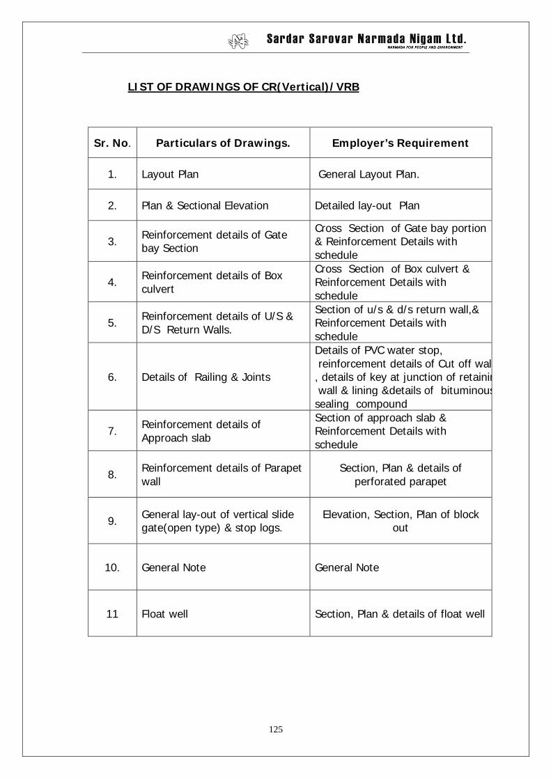
LIST OF DRAWINGS OF CR(Vertical)/VRB
Sr. No. Particulars of Drawings. Employer’s Requirement
1. Layout Plan General Layout Plan.
2. Plan & Sectional Elevation Detailed lay-out Plan
3. Reinforcement details of Gate bay Section
Cross Section of Gate bay portion & Reinforcement Details with schedule
4. Reinforcement details of Box culvert
Cross Section of Box culvert & Reinforcement Details with schedule
5. Reinforcement details of U/S & D/S Return Walls.
Section of u/s & d/s return wall,& Reinforcement Details with schedule
6. Details of Railing & Joints
Details of PVC water stop, reinforcement details of Cut off walls, details of key at junction of retaining wall & lining &details of bituminoussealing compound
7. Reinforcement details of Approach slab
Section of approach slab & Reinforcement Details with schedule
8. Reinforcement details of Parapet wall
Section, Plan & details of perforated parapet
9. General lay-out of vertical slide gate(open type) & stop logs.
Elevation, Section, Plan of block out
10. General Note General Note
11 Float well Section, Plan & details of float well
126
LIST OF DRAWINGS FOR SUPERPASSAGE Sr.No. Details of Drawings Employer’s Requirement
1 General lay out plan Detailed lay-out Plan
2
Details of reinforcement for super structure
Section of Super structure & Reinforcement Details with schedule
3
Details (RCC / PCC ) for components
Details (RCC / PCC ) for components
4
General notes
General notes
127
Chapter – 11
Employer’s guidelines for detailed designs
The Employer has finalized detailed norms for designs and drawings relating
to canals and canal structures, which are being presently used for designs
and drawings. The contractor shall have to carry out the design function in
total compliance of these detailed norms listed herein below:
1) GUIDELINES FOR DESIGN OF CANAL SECTIONS OF NARMADA MAIN CANAL
2) GUIDE LINES FOR DESIGN OF HEAD REGULATOR ON BRANCH CANALS
3) GUIDE LINES FOR DESIGN OF ESCAPE ON BRANCH CANALS 4) GUIDE LINES FOR DESIGN OF CANAL SYPHON ON BRANCH CANALS 5) GUIDE LINES FOR DESIGN OF DRAINAGE SYPHON / CULVERT ON
BRANCH CANALS 6) GUIDE LINES FOR DESIGN OF ROAD BRIDGES ON BRANCH CANALS 7) GUIDE LINES FOR DESIGN OF SUPERPASSAGE ON BRANCH CANALS 8) GUIDE LINES FOR DESIGN OF CROSS REGULATOR GUIDE LINES FOR
DESIGN OF CROSS REGULATOR/FALL ON BRANCH CANALS 9) GUIDELINES FOR GATE DESIGN
Computer disks containing these guidelines are also available and can be
obtained from the Chief Engineer, designs, Sardar Sarovar Narmada Nigam
Limited Block No. 12, Gandhinagar.
The EPC contractor shall follow the relevant and applicable guidelines for his
design purposes and for any queries and clarifications he shall contact the
Chief Engineer (Designs) at the addressed mentioned hereinabove.
128
GUIDE LINES FOR DESIGN OF CANAL SECTIONS OF
NARMADA MAIN CANAL
1.0 Introduction
1.1 Sardar Sarovar (Narmada) Project envisages construction of a concrete gravity dam across the river Narmada,146.50 m. (480.60 ft.) high above mean sea level near village Navagam in Bharuch district to impound a reservoir with gross storage capacity of 0.95 m. ham (7.7 MAF) and a live storage capacity of 0.58 M ham (4.73 MAF) at FRL. The project is planned to provide an annual irrigation to an area of 1.8 million hectares (4.43 million acres) besides providing Municipal and Industrial uses to about 4720 villages and 131 urban centers located within as well as out side the command. A series of four ponds on right bank are created to act as a balancing reservoir between main reservoir and canal system that will take care of diurnal variations in discharges required for irrigation and canal head power house. The Narmada Main Canal (N.M.C) off takes from pond – 4.
1.2 The N.M.C. is aligned as a contour canal having its total length of 460 km. from its off-take near dam site to the Gujarat-Rajasthan border. The canal will serve an area of 75000 hectares (185325 acres) annually in Rajasthan. The discharging capacity of the main canal is 1133 cumecs (40000 cusecs) at the head and 71.10 cumecs (2500 cusecs) at the Gujarat-Rajasthan border. The section of the main canal in its head reach is 73.10 m x 7.6 m. and at tail is 10.10 m x 4.4 m. (FSD) with tentative side slope of 2 (H): 1(V). The slopes however are finalized based on the safety requirements considering the properties of soils encountered during execution. A free board of 1.5 m. (1.25 m. lined + 0.25 m. unlined) is provided. The entire canal is lined with machine placed concrete of thickness 12.5 cm. on slopes and 10.0 cm. in bed. The bed gradient of 1:12500 UP TO Mahi river crossing and 1:15500 beyond Mahi to Rajasthan border
129
is fixed for main canal. 1.3 The N.M.C passes through varying Geographical terrain
throughout its run to Rajasthan border. The advantage of past experience in planning, design and construction of canal with such a large capacity (1133 cumecs) is not available anywhere. The norms viz. (i) Requirement of data (ii) Design criteria i.e. stability analysis of Canal sections, internal drainage arrangements, slope protection on land side etc, are given for guidance in following paragraphs. The criteria evolved are based on available literature on the subject, criteria given in relevant Indian standards and practice followed elsewhere on large canals. This criteria is reviewed from time to time based on the experience gained during the course of investigation, design and construction on this project and other projects.
2.0 SALIENT FEATURES
Criteria and salient features, for NMC are annexed vide Annexure-I. It may be however, mentioned here that for embankment/depth of cutting greater than 6.0 m. stability analysis is carried out using Swedish slip circle method. Typical cross sections along with details of components are given vide plate ;No.1 & II.
3.0 INVESTIGATION AND DATA REQUIREMENTS
N.M.C passes through varying topographical terrain having wide variation in soil characteristics. Maximum banking as high as 17 m. and maximum cutting also of about 17 m. in some reaches have to be provided. The structure safety of such a large canal can not be ignored. As such design based on adequate soil testing is the prime requirement.
Guide lines for collection and furnishing of data for design of canal section are enumerated below.
3.1 GENERAL DATA:
a) Canal alignment and vicinity survey: The canal alignment shown on the village plan (scale
130
1:7920) indicating additional features viz. Contours, hills, local depressions, nallas, borrow areas, village site, roads etc.
b) Proposed cross-section of the canal showing the ground profile, CBL, FSL, zoning i.e. type of material proposed to be used in bank (with the help of flow chart) etc. for
i) Maximum banking ii) 5.0 m. banking and iii) Maximum cutting. c) Longitudinal section (scale 1:3000 (H) & 1:200 (v) )
along the C/L showing continuous chainage, GL, CBL, FSL, TBL, logging of strata (indicating Lab No. & strata R,L.), rock profile if any, location of structures, premonsoon and postmonsoon ground water table line (when the ground levels are likely to be near or above the CBL with the year in which the said levels were observed etc.). The ground levels at 30 m. c/c on the cross sections taken at about 150 m. along the canal alignment should be given on the plan.
d) Condensed LS on the centre line of the alignment showing the full details as stated in 3.1 (C).
(Scale: Hor. 1 :10000 Ver. 1; 200).
e) Flow chart indicating availability of materials from canal excavation based on soil classification in groups as shown in annexure II and the requirement of material with cross section adopted. The flow chart should also indicate the reach/borrow area from where the material is to be transported / borrowed in case of deficiency. Planning of surplus material should also be indicated. A note justifying the proposed zoning should be attached
f) For deciding strata/layer wise design constants for foundation material, the R.L. from which the soil samples have been taken may be given instead of giving only depth. Also the G.L. and lab. Nos. of trial pits/bore holes may be given on the L.S.
131
3.2 FOUNDATION AND CONSTRUCTION MATERIAL SURVEY:
3.2.1 Trial pits/bore/auger holes (i.e. along C/L may be taken at about 3000 m c/c to 5000 m c/c as per ground profile . The trial pit/bore hole may be taken down to about 4.0 m. below the C.B.L. However, in case where the canal is in high bed banking, trial pits about 2 m. deep below the ground surface are required to be taken.
The spacing of the trial pits may be reduced where the surface profile indicates rapidly changing strata. For every 2 km at least one bore hole should be drilled down to rock or other continuous impervious stratum in order to ascertain the infiltration characteristics of the strata in the vicinity of the canal. The visual logs of the trial pits and bore holes should be prepared and furnished to the design office.
In the case of the bore holes, details such as colour of wash
water, water loss at various depths, time rate of penetration etc. should be noted and recorded for proper appreciation of the sub soil conditions.
3.2. The samples may be collected as given below. Sr.No
Location of trial/bore holes
Nature of samples to be collected from trial pits/bore holes along C/L
A. Canal in cutting Between the stripped level and CBL
Undisturbed and disturbed (Alternatively at 1.5 m. interval with at least one undisturbed sample irrespective of the depth)
2. Below CBL Undisturbed (At 1.5 m. interval with a minimum of one sample)
B Canal in partial/full banking
1. Between stripped level and CBL
Undisturbed and disturbed (as in A-1)
2. Below CBL Undisturbed (As in A-2)
132
3. Borrow area (if required)
Disturbed (One sample for every 1.5 m. depth or change in stratum whichever is less)/
Sample should not be collected from top layer, which is required to be stripped. In case of the bore holes, details such as colour of wash water, water loss at various depths, time rate of penetration etc. should be noted and recorded for proper appreciation of the sub-soil condition.
3.2.3 For cohesive ( C –ø) material as well as fine grained soils, at least one sample for each stratum met with or at every 1.5 m. depth whichever is less should be tested as below.
Nature of sample Tested for
Disturbed samples MA, AL, Proctor and shear parameters on sample remolded at 95% MDD &
Note:- Laboratory permeability test should be carried out at least for one undisturbed and one remolded sample of the representative soil in each trial pit.
3.2.4 Where material is cohesion less, the maximum and minimum density tests should be carried out on the disturbed sample. The tests for engineering properties and shear values for the material should be carried out on samples from various depths remolded at 65% relative density. If it is possible to collect undisturbed samples, the soil tests should be carried out on such samples at FDD and FMC. For the soil strata where the canal is in partial or full cutting, Vane shear tests (IS 2720 (Part – 30) 1980) at 1.5 m. intervals should invariably be carried out if undisturbed samples can not be collected.
133
3.2.5 BORROW AREA
i) The soil samples should be collected by excavating trial pits spaced suitably, based on the area, nature of soil, type of deposit etc. However initial spacing of about 400 m c/c is suggested for guidance. The spacing need not be closer than say 100 m c/c. The final spacing should however be decided by the concerned Executive Engineer in consultation with the Executive Engineer (Quality Control).
ii) The depth of borrow pit depends on: a) The types of excavating units and the quantities to
be borrowed with respect to the nature of the soil and the land area available,
b) The safety during borrowing of material. c) The ground water table d) The hard stratum horizon.
iii) During excavation of the trial pits the field engineer not below the rank of Deputy Executive Engineer (responsible for investigations, construction and testing) should keep close watch on the soil available from the borrow pits.
iv) If the soil available differs appreciably, based on visual observation from the type of soil required, it should be immediately reported to the Executive Engineer who inturn should take suitable action in consultation with the Executive Engineer (Quality Control).
v) If the soil properties marginally differ, based on the visual observation, the problem should be reported to the Executive Engineer with the representative results of MA & AL tests of the soil. Then the Executive Engineer should decide in consultation with the Executive Engineer Quality Control, whether the investigations with the same borrow area should be continued or otherwise.
134
3.3 LABORATORY TESTS.
The samples collected as per para 3.2 above may be tested as below. The relevant Indian Standard should be followed for the procedure for soil testing. The list of Indian Standards is given vide Annexure-IV.
3.3.1 MECHANICAL ANALYSIS AND ATTERBERG’S LIMIT TESTS
These tests may be conducted for undisturbed/disturbed samples from trial pits/bore holes along canal alignment and borrow area (as per Para 3.2.2). These tests should be carried out only after the permeability and shear tests are carried out in the case of undisturbed samples.
3.3.2 PROCTOR COMPACTIONS
The standard proctor tests may be carried out for disturbed samples (as per para 3.2.2.) representing the soils proposed to be used in the canal banks. When at least 20% material is coarser than 4.75 mm. size, gravel corrected densities and moisture content may be given. When the higher compacting efforts are applied in the field, to simulate this in the laboratory, modified proctor tests may be performed.
3.3.3 INSITU DENSITY
The insitu density test should be carried out on the undisturbed samples collected from the trial pits as per para 3.2.2. (The dry densities and void ratios, gradation analysis and index properties may also be given. These data will be helpful in assessing whether the foundation material is likely to collapse on saturation or during earth quake).
3.3.4 RELATIVE DENSITY
a) Disturbed samples for banking: The relative density test should be carried out insitu at
various depths in the trial pits in the case of purely
135
cohesion less soil using the result of maximum and minimum densities as mentioned in para 3.2.4. The samples for shear test may be prepared at 65% R.D.
b) Insitu properties for soil
3.3.5 SHEAR TEST: The procedure adopted for the test should simulate the field
conditions viz. (i) The normal load and / or confining pressure (only for triaxial test) to be applied on the sample in the direct shear test should simulate the over burden pressure likely to act at the end of the construction. (ii) The drainage conditions and the rate of shearing adopted for carrying out the tests should also match with field conditions. (a) Box Shear Test:
The consolidated undrained shear tests should be carried out on the disturbed and undisturbed samples. For disturbed samples the shear tests should be carried out on the samples remolded at OMC with 95% proctor MDD. For undisturbed samples the tests should be carried out at FDD, FMC. When at least 20% material is coarser than 4.75 mm. size, large size box shear tests should be carried out. The details of test procedure should invariably be given. For test procedure IS 2720-Part 13-1986 should be followed. (b) Triaxial Tests:
At least 10% of the (disturbed and undisturbed) samples should be tested in triaxial shear test apparatus for consolidated undrain shear tests with pore pressure measurements. The consolidated undrain shear tests in box shear apparatus should also be carried out for these samples. In the case of undisturbed samples, this requirement will necessitate collection of two similar sample from the same location. The values may be given for total stress and effective stress (considering pore pressure) separately for comparison. For test procedure IS 2720 (Part-12) 1981 should be followed.
136
3.3.6 PERMEABILITY TEST:
The permeability test should be carried out on representative samples. When at least 20% material is coarser than 4.75 mm. size, large size parameter should be used. Field permeability tests wherever required should be carried out in consultation with the Design Circle. Field test should always be preferred to the laboratory tests wherever possible. IS 5529 (Part-I) 1985 should be followed.
3.3.7 (a) CONSOLIDATION TESTS:
When the foundations of a structure or any of its components consist of more than 2.0 m. deep compressible soil, consolidation tests should be carried out. The undisturbed samples should be collected at mid depth of overburden below the structure. The values of coefficient of consolidation (Cv) compression index (Cc) and graph showing void ratio (on Y axis) V/S pressure on log scale (on X axis) may be given (e log P curve). In a continuous canal reach passing through compressible soils, consolidation tests on two or three representative samples should be carried out with loads and drainage simulating the field conditions. These tests will be helpful in assessing the likely settlement of foundations or the canal banks.
(b) TEST FOR SUDDEN COLLAPSE:
When foundation soils are fine grained uniform soils like salty sands, Sandy silts or non cohesive soils having R.D < 65%, sudden collapse tests under saturation and seismic loading should be carried out.
3.3.8 EROSION RESISTANCE TEST: The quality of soluble salts present and the equivalent sodium content in the soil and ground water may be given. For soils having PI less than 10%, the pin hole and crumb tests should be carried out to assess their erosion resistant characteristics.
137
3.3.9 SWELLING PROPERTIES. If high LL (> 55%) is accompanied with low shrinkage limit
(<10), Swelling pressure and free swell tests should be conducted as outlined in CWC Publications “Lining on expansive soils” June, 1987
3.4.0 RECORDING AND REPORTING THE DATA: 3.4.1 The trial pits/bore holes should be located on the L.S and the plan
showing the canal alignment. The trial pits/bore holes etc. should be numbered with suitable symbols.
3.4.2 The soil should be described in the logs and in the records according to IS No.1498 – 1970. The weak clayey layers, organic fills, loosely deposited sand lenses etc. should also be shown on the logs. The R.L. at the beginning of each stratum should be given.
3.4.3 The results of laboratory tests of all disturbed samples should be given. The suitability of the material for each zone should be based on the results of engineering properties of soils based on Appendix-A of I.S. No.12169-1987 (Annexure-II) An estimation of quantities of different types of soils viz. (i) CL, CI, CL-CI, (ii) SC, (iii) SM etc. available and required for bank should be given.
3.4.4 The borrow area plan and sections should be prepared indicating locations of trial pits and demarcating zones of different soils based on the engineering classification viz. (i) CL, CI, CL-CI, (ii) SC, (iii) SM etc.
4.0 COMPONENTS AND CANAL SECTION: A canal can either be in full cutting, partial banking or full
banking. A canal section in bank generally consists of following components. The zones however may be decided so as to accommodate practically all the excavated material. Only the balance quantity should be brought from the borrow area. i) core or impervious zone ii) casing or shell
138
iii) internal drainage system iv) surface drainage (seperately discussed in para -6) v) dowel. The functions and design requirements of these components are given below:
4.1 CORE:
The function of the core is to provide impermeable barrier in the body of the canal bank. Impervious soil with low to medium plasticity are suitable for core. Annexure-II shows the suitability of soils for construction of canal bank. Following guide lines are recommended for the design of the core. a)The core or impervious zone may be located either just
behind the lining or the centrally or inclined upstream, depending upon the stability requirement, availability of material etc. The impervious material having LL greater than 35 should not be placed behind lining.
b) The top of the core may be kept 0.50 meter above the FSL to prevent seepage by capillary siphoning.
c) Minimum top width of the core may be kept as 3.0 m. to facilitate proper compaction.
d) In case of bed banking the cores on both the banks should be connected with each other by an impervious layer covered with about 1.0 m. thick S.P. layers below the canal bed, if impervious material has LL greater than 35.
e) As far as possible the impervious zone of non expansive soil should be located just behind the lining. The top width of the zone can be 3.0 m. with slopes on u/s & d/s are as per provision of design requirement (Reference - IS code ). Adjacent to the impervious zone on the d/s side an inclined sand filter connected to the bottom horizontal filter should be provided if necessary . D/S of the inclined filter, all materials available from obligatory excavation should be suitably accommodated. If the availability of impervious material from the obligatory excavations is very substantial a thick central core should be attempted such that the width of the
139
u/s casing zone is sufficient to make the u/s bank slope stable under the sudden draw down condition. Filters may be provided as per requirement. If there is an u/s impervious zone and if the material for the casing zone is erodible, the outer portion of such an erodible zone can be covered suitably with erosion resistant impervious clayey material in case it is adequately available after meeting with the requirement of the u/s zone. A very thick u/s impervious zone should be avoided as otherwise the u/s outer slope probably become unstable in the sudden draw down condition.
4.2 CASING
The function of the casing is to impart stability and protect the core. Relatively pervious materials which are not subjected to cracking on direct exposure to atmosphere are suitable for casing. The top width of the canal bank should be provided as per canal bank section ( i.e 4.27 m on SR side & 2.50 m on IP side for branh canal ) . Beams may be provided about 6.0 m or as per design requirement . vertical interval. A beam width of 4.0 m.is desirable. The effective thickness perpendicular to the slope of the casing at the road level and at the beam level shall be 1.0 m. or more.
4.3 CANAL BANK
4.3.1 HOMOGENEOUS SECTION
An embankment of canal composed of single type of material.
4.3.2 RANDOM ZONE
The use of practically all the material available from the compulsory excavation may be planned in the appropriate zone. If this is not possible, the same may be used in a random zone which is generally located d/s of the inclined filter. Annexure-II may be referred for suitability of soils for construction.
140
4.4 INTERNAL DRAINAGE SYSTEM
The internal drainage system controls the seepage through the canal bank. The system generally consist of i) inclined filter, ii) horizontal filter, iii) rock toe cum toe drain, iv) pressure relief valves. The internal drainage should be provided for smaller bank height than the specified below, if required from safety considerations.
4.4.1 INCLINED FILTER:
The inclined filter is provided D/S of the impervious zone with or without transition zone in between, to collect seepage from the impervious zone and thereby keeps the d/s casing portion of the canal bank relatively dry. The inclined filter is to be provided in the cases where the canal section is in full banking or in bed banking. The filter material should be free draining having a permeability of 5 x 10⁻³ cm/sec or more. The inclined sand filter should be provided up to ¾ th height of FSD above CBL. It is preferable to provide inclined sand filter up to the FSL, where sufficient quantity of sand is available. The width of inclined sand filter should be kept 0.90 m.
4.4.2 HORIZONTAL FILTER:
The horizontal filter collects the seepage from the inclined filter and carries to the rock toe cum toe drain. It also collects seepage from the foundation and minimizes possibilities of piping of the canal seat. It is usually provided at ground level in the d/s of core or impervious zone. A d/s grade of about 1 IN 100 may be provided towards the rock toe for quick disposal of seepage water. i) The thickness of horizontal sand filter should be 30 cm.
(compacted) for partial banking (more than 5.0 m. height) and 60 cm. for the canal sections having full banking and bed banking.
141
ii) The horizontal sand filter of minimum thickness 30 cm. (compacted) may be provided where sufficient quantity of sand is not available.
iii) In a length of 15.0 m. adjoining cross drainage structure, the horizontal sand filter of minimum thickness of 60 cm. may be provided.
In case the upstream casing zone material has permeability less than 10-4 cm/sec. and high draw down pore pressures are apprehended, one or two intermediate horizontal sand filters might be considered in the zone. This should, however be avoided as far as possible by carefully selecting the upstream casing material. The design criteria for the filter material to be followed for horizontal/inclined filters is given in para 4.4.5
4.4.3 ROCK TOE CUM TOE DRAIN: The function of rock toe cum toe drain is to facilitate drainage of seepage water and to protect the lower part of d/s slope from accumulated surface water. The rock toe cum toe drain is provided at the d/s toe of canal banks to collect seepage water from the horizontal filter and to discharge it may from the bank. i) The design of rock toe should generally be provided
if the bank height exceeds 5.0 m. However the rock toe should be provided for smaller bank height for safety considerations. Where the horizontal filter is provided in the section. The design of rock toe should be adopted as given in Plate-II.
ii) In a length of 15 m. adjoining the cross drainage structures, the height of rock toe should be provided as h/6, where h is hydraulic head. The details of components are shown in Plate-II.
4.4.4 PRESSURE RELIEF VALVE
A lined canal crosses areas subject to seasonal high ground water or where the soil is sufficiently water tight to prevent the free draining of the seepage/leakage from the canal.
142
Pressure relief valves protected by surrounding graded filters are provided on the canal slopes and in the bed to relieve excess hydrostatic pressures behind the lining. These one way valves open out in the canal to drain the water from behind the lining. The PRVs should normally be provided where the permeability value of the sub grade either in cutting or in banking is between 10-4 cm/sec and 10-6 cm/sec. To reduce the pore pressures in the upstream casing zone, for stability requirement, the PRVs with 0.15 m. thick (minimum) horizontal filter blanket (preferably 0.30 m thick) can be provided irrespective of the permeability value of the sub grade. These horizontal filter blankets may extended in the portion (casing and/or core) in which the pore pressures are required to be lowered. In case these blankets extend in to the core, the effective thickness of the core beyond the toe of the horizontal filter blanket should not be less than one third the hydrostatic head acting at the point.
(I) Where the sub-soil water level is below CBL
Size of P.R.V.
Spacing along
Canal.
Location
150 mm dia. 50 mm dia.
16 m c/c 16 m c/c
Four in bed and two on slopes as shown in Plate –IV at lower elevation. Two at higher elevation on slopes (one on each slope)
(II) Where the sub soil water level is above CBL, following measures
could be considered. (i) Raised bed humps up to 1/3rd height of canal FSD can
be provided and kept filled with water to provide counter weight of uplift pressure. Till then some portions at suitable integrals can be left unlined to allow direct drainage and release of pressure.
143
(ii) Deep tube wells can be installed outside the banks. The water can be pumped in to canal to augment the supply
(iii) The pressure release valves may be provided in Narmada Main Canal (Refer Plate-IV) . The details of lining and under drainage arrangements are shown in Plate III & IV ( provided in Narmada Main Canal) .
(III) Where the sub soil water level is close to FSL. The under drainage arrangements may be provided as shown
in Plate V. If necessary, some additional measures like (i) & (ii) in (II) above could also be considered.
4.4.5 FILTER CRITERIA
The filter material should be well graded. It should not usually contain more than 5% material passing through 75 micron IS sieve and should not have size greater than 75 mm. So as to minimize segregation and bridging of large size particles. It should satisfy the following standard filter criteria between the adjoining zones. (a) D 15 (f)
------------ > 4 and < 20 D 15 (b)
(b) D 15 (f) ----------- < 5 D 85 (b)
(c) D 50 (f) --------- < 25 D 50 (b)
(d) The gradation curves of the filter material should be nearly parallel to the gradation curves of the base material. In (a), (b), (c) above, the suffix,
f = filter material b = base material
144
and 15,50,85% particles by weight respectively are finer than D15,D50, and D85 particle sizes.
4.5 DOWEL:
(I) We can have concrete parapet T shaped or L shaped dowels. The dowels edge may be 30 cm. away from the water side edges of the canal bank top.
(II) An earth dowel provided on the canal side edge of the bank provides an extra free board over and above the normal free board of 1.5 m. It prevents the surface water from entering in to the canal or behind the lining and prevents undermining of the soil below the lining. The top width, height, canal side & road side slopes of the dowel are proposed 1.0 m, 0.60 m, 2(H):1 (V) and 1.5 (H): 1 (V) respectively. Dowels may be replaced with parapet walls at the structures.
5.0 STABILITY ANALYSIS:
For the design of the canal bank, the alignment is divided in small reaches based on the following considerations. (a) The quantity of banking material required is obtained to
the maximum possible extent from the same slice from the cutting so that necessity to bring material from longer leads or from the borrow areas is minimized.
(b) As far as possible the transportation of materials remains within the major drainage crossings.
(c) There is not much variation in the properties of soils in the same slice so that the slopes as per the stability analysis remain identical for the whole reach.
5.1 SOIL PARAMETERS:
The suitability of material for each zone is decided based on results of engineering and index properties of soils and the criteria given in Annexure-II. For the foundation, the test results of undisturbed samples are required as mentioned in
145
Para 3.2 .A good number of consistent test results for each zone of the embankment and for the foundation material are necessary. 75% reliable values of MDD/FDD & Ø are obtained from the test results of disturbed and undisturbed samples and the corresponding values of OMC/FMC and ‘C’ respectively are adopted for the data and used as design constants. Lining, filters and rock toe cum toe drain are not considered in the stability analysis as they form a small portion of the canal bank.
5.2 PORE PRESSURE:
Pore pressures for various materials are assumed as under:
cm/sec. K > 10-4 cm/sec. Foundation K>10-6 Above C.B.L Below C.B.L.
50% X 25% X Nil Nil Nil
100% X 50% X Nil 50/100* 100*
100% 50% Nil 100* 100*
Remarks:- The figures are percentages of water columns equal to the height of the height of the embankment over the trial failure surface at various point.
X The pore pressures to be considered can be reduce to
half the values given above if horizontal filter mats are provided in the canal side casing of the bank. (Please. see Para 4.4.4.)
* For foundation strata of impervious type material.
The pore pressures are accounted in terms of heights of water columns. In operating and sudden draw down
146
conditions the buoyant weights are considered.
5.3 SAEISMIC-COEFFICIENT:
The horizontal component of seismic coefficient is worked out by seismic coefficient method given in the IS – 1893 – 1984 (Third Revision) on “Earth quake resistant design of structures”. The map of India showing seismic zones is referred for deciding the zone in which the canal bank is situated. The importance factor for NMC is however adopted as 2.0 against 3.0 for the dam. Only the horizontal component of seismic coefficient is considered in the analysis.
5.4 METHOD OF STABILITY ANALYSIS:
The stability analysis of canal bank is carried out by Swedish slip circle method of analysis. The effective stress method is adopted as recommended by IS 7894 – 1974” Code of practice for stability analysis of earthen dams”. In this method the factor of safety is worked out for a number of trial failure planes (Circular) which are adopted based on the geometry of section, zoning, properties of the material, boundaries of drawdown etc. The Canal side slope is checked for the construction and sudden drawdown conditions. Where as the land side slope is checked for the construction and steady seepage conditions. The operating condition or the steady seepage condition is also checked for earthquake effect. The factor of safety is worked out for each failure surface and the minimum value should not be less than the permissible value.
5.5 ACCEPTABLE FACTOR OF SAFETY :
The permissible value of factor of safety for each condition is given below.
Slope Condition Permissible value of factor of safety as adopted for NMC
As per I.S.
U/S i) End of construction 1.0 1.0
147
Slope *ii) Operating condition.
a) Without earth quake
b) With earth quake iii) Sudden
drawdown condition.
1.3
1.0
1.0
- - 1.3
D/S Slope
i) End of construction ii)Steady seepage
condition. a) Without earthquake b) With earthquake
1.0
1.5 1.0
1.0 1.5 1.0
Note:-(1)As decided during the 11th BOC Meeting checks for operating condition with and without earthquake may not be performed for the canal side slope.
(2)In the third Meeting of the Board of Consultants the minimum desired factor of safety under sudden draw down condition was reduced to 1.0 with controlled drawdown for U/S slope. This is being followed since then.
6.0 PROTECTION TO OUTER FACE: The Narmada Main Canal 460 km. long runs in partial
banking and full banking up to 17 m. height in considerably long reaches. The top width the of service road is 8.0 m. The outer slopes of the canal banks are 2(H): 1(V). The rain water may, therefore, run down the slopes at high velocity, eroding the canal banks. The erosion may be leading to finally deep rain cuts. These rain cuts shall have to be filled with compacted earth during maintenance, which is a very tedious work apart from being exceptionally costly and susceptible to serious damage.
In order to cut down the maintenance cost and minimize unforeseen problems due to erosion, the following measures (Broad guidelines) are proposed to protect the banks
6.1.1 SOIL CONSERVATION:
Rain water falling over the earthen bank and rolling down
148
the d/s slope of the bank will lead to sheet erosion. Sheet erosion strips the soil from unprotected surface of the earthen bank and moves down the slope with run off water. Sheet erosion leads to rill and then gully erosion. Vetiver grass is a useful plant to prevent soil erosion economically. The vetiver grass with its fibrous rooted shrubs and grasses planted as hedges along the contour can prevent the sheet erosion. They slow down the run-off water, spread it out, take erosive power out of it, filter out the soil it is carrying and let the filtered run off proceed down the slope gently without any further erosive effect. Vetiver grass is the ideal plant for this purpose. It has the following characteristics that make it ideal for soil conservation and stabilization. The details are given in Plate-II. (a)It is extremely cheap, because once the vetiver nursery is
established; the planting material can be received at no cost.
(b)It has a deep strong fibrous root system. (c)Planted at the correct distance it will quickly form a dense
hedge, under-lain by a dense curtain of roots binding the soil along contour.
(d)Once established, it is generally unpalatable to live stock. (e)It is perennial and will last as a hedge, not requiring
maintenance for years. (f)It can withstand fires, droughts, inundation and floods. (g)Its leaves and roots have demonstrated a resistance to
most pests and diseases. 6.1.2 Slope protection with vetiver grass along with surface drainage
arrangements as mentioned in Para 6.3 would help to arrest erosion of banks. However in acute cases the bank slopes can be protected with a cement stabilized or lime stabilized plating layer 25 to 30 cm. thick laid over the slopes and compacted with twin slope compactors. Pilot test strips of suitable lengths shall have to be laid before taking up such work on a large scale. The cement soil proportions, method of mixing, moisture content, lift thickness, number of passes of compactors etc. shall be decided based on such tests.
149
6.2. CATCH WATER DRAINS
The rain water falling over the top of bank and on the slopes moves down the slopes eroding the slopes. It is necessary to provide a system of drainage arrangement i.e. the catch water drains horizontally along the bank as well as inclined on the surface of the bank. These drains will collects rain water at every 6.0 m. vertical height and finally discharge the water beyond the toe of the bank. It is proposed to provide horizontal drains of 15 cm. dia half round pipes or brick/stone paved drains at tops of banks and at beam level i.e. at every 6.0 m height. The drains paved with brick/stone/ cc (0.30 m. x 0.15 m) are however preferred to the 15 cm. dia. Hale round pipes. The inclined drains of 15 cm. dia half round pipe or brick paved drains are proposed at 90 m. c/c along the canal banks. A brick masonry Kundi is proposed at every junction of the horizontal and the inclined drain. The details are given in Plate-II for ready reference.
6.3. OUTFALL HOLES IN TOE DRAIN:
The toe drain is provided at the d/s toe of the bank to collect seepage from the horizontal filter and to drain it safely away from the toe In order to avoid choking of rock toe it is proposed to fill the voids in exposed surface, with pointing with cement sand mortar, along the entire length of canal where toe drain is provided. It is necessary to provide the outfall holes in the toe drain from where the seepage water collected in the to drain can be drained out, otherwise there will be rise in water level in the d/s casting zone. The out fall holes in the toe drain shall he provided at every change of gradient at d/s toe or maximum 300 m. distance. The details are shown in Plate-II.
7.0 QUALITY CONTROL CRITERION:
The N.M.C 460 km. long, runs in partial banking and full banking in considerably long reaches. In order to obtain
150
uniform and proper quality control along the entire alignment, following guidelines related to earthwork in canal bank construction should be followed.
In order to carry out construction of canal banks and concurrent investigation on uniform lines the technical circulars issued are given in Annex-VI for guidelines.
7.1 The canal bank consists of zones having fill materials of
different characteristics. All zones should be raised simultaneously and to lines and levels as shown on the drawings. The properties of the bank material should be as specified in the design note and drawings. In case the material as specified in the design note is not available, the problem should be referred to Narmada Project Design Circle,, Gandhinagar for review of the design.
7.2 The roller should travel in the direction parallel to the
alignment of the canal. For rolling at the junction between two adjacent zones, the roller with low rolling pressure suitable for any of the two adjacent zones, should be used. The rolling at the junction should be done in such a way that the joint between the zones falls more or less in the middle of the roller width.
7.3 The dry density attained should be at least 95% of the MDD
(standard proctor) obtained in the laboratory for the material. If the field density achieved is less than the design density, the data should be furnished to the Narmada Project Design Circle, Gandhinagar to review the design.
7.4 For cohesion less material, the relative density of the compacted
material should not be less than 65% as determined by laboratory tests.
7.5 Field officers should be impressed upon about the importance of
drainage and protective filter arrangements within the body of the earth bank. Proper quality control regarding the type of
151
material, gradation and avoidance of contamination by the adjacent zone materials should be exercised by the field officers. The thickness of the filter and the continuity of the filters should be properly maintained in the whole length of the earthen bank during the execution. The horizontal filter should be completed and covered with suitable soil at the earliest so as to avoid contamination with foreign material. In the case of less cohesive soil or erodible hearting core soil, it is all the more necessary that the filter criteria in the direction of flow are strictly satisfied. If the filter criteria between any two zones is not satisfied the problem shall be referred to Narmada Project Design Circle, Gandhinagar to review the designed section.
7.6 For proper bond with the constructed canal bank, the new earth work should be carried out and finished as under.
7.6.1 In case the constructed bank is to be extended horizontally, the uncompacted soil from the end of the old bank should be removed and it should be cut to a slope not steeper than 1 in 3. The cut surface should be scarified properly just in advance of placing a new earth layer, to form benching steps of the height equal to the layer thickness and moistened. New earth layer should be laid with proper moisture content and compacted simultaneously with the adjacent old earth work so as to form homogeneous earthwork at joint.
7.6.2 If the existing bank is to be raised vertically, vegetation lose earth, organic material etc. should be cleared. Rain cuts, if any should be shaped so as to remove the loose soil. The rain cuts then should be filled up with compacted earth work. Surface should be made loose at least for a depth of 15 cm. necessary watering should be done and new material should be laid in layers and compacted.
7.7 Proud should be cut just prior to execution of lining. At the time of cutting the proud it should be ensured that the cut surface is well compacted earth.
7.8 If expansive soil is met with during excavation of the canal in partial or full cutting, the problem should be referred to
152
Narmada Project Design Circle, Gandhinagar along with necessary details viz. engineering properties, swelling pressure and free swell index of expansive soil and the engineering properties of the CNS material from canal excavation and/or borrow area etc, to evolve suitable treatment as may be necessary.
8.0 BOARD OF CONSULTANTS (BOC)
The design of the canal banks is prepared in house by the NPDC, Gandhinagar. As per suggestion of the World Bank, Sardar Sarovar (Narmada) Project Authority has set up the Board of Consultants (BOC) comprising independent experts to conduct periodic reviews of the design and the construction of N.M.C. The recommendations of the BOC for specifically identified problems (Agenda items as listed in Annexure-V) are incorporated in the design of the canal banks. In addition, for intricate problems related to the safety of the canal banks, the services of experts in the corresponding field are utilized.
9.0 SPECIAL PROBLEMS:
9.1 EXPANSIVE SOILS AND CNS MATERIAL
(Ref: 6th meeting of BOC held at Vadodara from January 19-21, 1988) Expansive soils contain Montmorillonite or combination of Montmorillonite and Elite clay minerals having expanding lattice in the clay fraction. It exhibits heave when moisture content increases. Cohesive non-swelling soils (CNS) possess cohesion but do not exhibit heave. Swelling soil behind the lining may exert a high pressure on the lining. It is therefore replaced with CNS soil of adequate thickness to counteract the swelling pressure.
The testing, design and construction of the CNS layer should be carried out as per Central Water Commission Publications “Lining of Canals in expansive soils” June, 1987. Slope
153
stability of the canals in cutting in expansive soils should be reviewed after carrying out triaxial shear tests simultaneously on samples taken out from the same location both in the project laboratory and in GERI for comparison and confirmation of test results.
9.2 MICA SCHIST:
(Ref: 6th meeting of BOC held at Vadodara from January 19-21,1988) The recommendations of BOC are as under: a) The weathered Mica-Schist may be used only in the outer
zone of the canal embankment. b) To see if 95% proctor density can be achieved in the field,
field trial should be conducted with smooth drum roller. If required density can not be achieved with reasonable efforts with smooth drum roller then only the density criteria may be relaxed.
c) The concrete lining should not be placed directly on top of Mica-Schist layer. The Mica-Schist layer. The Mica Schist layer should be over excavated by at least 1.0 m.(horizontally) on sides and 0.30 m. in bed and back filled with semi-pervious type of soil to a compactable width and compacted to achieve the 95% proctor density.
9.3 ML TYPE OF SOIL:
(Ref:- 7th meeting of BOC held at Vadodara from June 28- 30,1988). The recommendation of BOC are as under. a) The treatment of sub-grade as decided for Mica-Schist
strata during the 6th BOC meeting should be followed in this case also.
b) To take care of settlement problem, the bed should be soaked with water so that prior to laying lining over it, it gets settled to the maximum extent possible.
9.4 SM TYPE OF SOIL:
(Ref: Agenda item No.7,11th BOC held at Vadodara from 26-
154
28 February, 1991)
The canal traverses in reach where SM soils are predominant The canal section in this soil is not safe from stability consideration and from erosion of slope during monsoon.
The recommendation of BOC are as under:
(A) Stability i) As the canal supplies were to be regulated very
carefully and further for reasons explained in paras 3.1 and 3.3. the Nigam may not perform the checks for operating condition with and without earth quake.
ii) In respect of check of sudden draw down condition the safety factor of 1.0 as approved already would stand, although the Nigam might carry out the stability on the basis of revised values of C and Ø which would correspond to the values as would obtain in the field.
iii) In banking soil abutting the lining should be the best available.
(B) To protect the banks from erosion.
i) It would suffice to provide a small pucca drain on the outer side of banks, which should intercept rain water and carry to the drain to be provided at suitable intervals along the sloping portion of the bank. Suitable plants be grown on the slope to provide cover.
9.4.2 Though drainage combined with vegetative protection may suffice in many cases, special protection as mentioned in Para 6.2 might be required in certain cases.
9.5 Drainage arrangements where water table is high (reach from ch..124 to 144 km of Narmada Main Canal)
For above length of 20 km. where the depth of sub soil water level is in the range of 9 m. and above or close to full supply level, additional drainage arrangement need to be provided and in others, raised bed humps up to 1/3rd height of canal be
155
provided. Keep filled with water to provide counter weight of uplift pressure. Till then, some portions be left unlined to allow release of pressure (although not applicable in this case, deep tube wells could be installed out side the bank to keep water table low and to pump it in to the canal and augment the canal supplies). Drainage system need to be provided in the area served by Panam reservoir. It should have suitably placed cross drains from the higher land to the lower land in command.
As regard the design to be adopted, where additional drainage is to be provided the proposals made by the Nigam are modified as under.
In the bed, drains need to be only two longitudinal on the sides. There is also no need to have cross drains in the bed. However pressure release valves will be provided in the bed as in the past. On the slope cross drains proposed by the Nigam were approved. These longitudinal and cross drains will have perforated pipes embedded with filter around them and they will be suitably sloped along the canal bed.
Protection to outer face of canal bank by
Vetiver grass and toe drain arrangement.
156
Sardar Sarovar Narmada Nigam Ltd., Gandhinagar
Technical Circular No.NMC-1090-38-M Dated: 5th April, 1990
Circular The Narmada Main Canal 460 km. long runs in partial
banking and full banking in considerably long reaches. The rain
water running down the slopes at critically high velocity,
eroding the canal banks. The rain water carries earth particles in
the rock toe, thus chocking it and nullifying the very purpose of
the rock toe. During the inspection, the minor cuts were noticed
at some places on canal banks.
It is therefore directed to take following measures to prevent
soil erosion on outer face of canal banks and chocking of rock
toe.
1. Stabilization of slopes may be accomplished by the
establishment of vetiver grass. It is the ideal plant for this
purpose, so it should be planted as hedges along the contour
of bank, at very 3 m. vertival interval and along outer toe of
the top width and berms, as shown in sketch 1.
2. Horizontal and inclined surface water drains may be provided
to collect the rain water and finally discharge the water
beyond the toe of bank, as shown in sketch-1 and 2.
157
3. The voids in exposed surface of the rock toe should be filled
up with cement sand mortar to prevent the chocking of rock
toe. The out fall holes from rock toe should be provided as
shown in sketch-1 and 3 attached herewith.
It is further directed that careful and strict supervisions
should be arranged to see that the soil erosion is not taken place
on outer face of canal bank and the rock toe is prevented from
chocking by the loose earth rolling down from upper levels.
158
Sardar Sarovar Narmada Nigam Ltd., Gandhinagar.
Technical Circular No.NMC-1090-38-M
Dated 16th April, 1990.
Circular
Narmada Main Canal, 460 km. long, runs in partial banking
and full banking in considerably long reaches. In order to obtain
uniform and proper quality control along the entire alignment,
following guide lines related to earth-work in canal bank
construction should be followed.
1.0 The embankment consists of zones having fill materials of
different characteristics. All zones should be raised
simultaneously and to lines and levels as shown on the
drawings. The properties of the bank material should be as
specified in the design note. In case the material as
specified in design note is not available, the problem
should be referred to N.P.M.Canal Design Circle No.1, for
review of the design.
2.0 The roller should travel in a direction parallel to the
alignment of the canal. For rolling at junction between two
adjacent zones, the roller with low rolling pressure suitable
for any of the two adjacent zones, should be used.
3.0 The dry density attained should be at least 95k% of MDD
(Standard proctor) obtained in the laboratory for the
material. If the field density achieved is less than the
159
design density, the data should be furnished to
N.P.M.Canal Design Circle No.1, to review the design.
4.0 For cohesion less material, the relative density of the
compacted material should not be less than 65% as
determined by laboratory test.
5.0 Field officers should be impressed upon about the
importance of drainage and protective filter arrangements
within the body of the earth bank. Proper quality control
regarding the type of material, gradation and avoidance of
contamination by the adjacent zone materials, should be
exercised by the field officers. The thickness of the filters
and the continuity of the filters should be properly
maintained in the whole length of the earthen bank during
the execution. The horizontal filter should be completed
and covered at the earliest so as to avoid contamination
with the foreign materials.
6.0 For proper bond with the constructed embankment, the
new earth work should be carried out and finished as
under.
6.1 In case the constructed bank is to be extended horizontally,
the uncompacted soil from the end of old bank should be
removed and it should be cut to a slope not steeper than 1
in 3. The cut surface should be scarified properly just in
advance of placing the new earth layer, to form benching
steps of the height equal to the layer thickness and
moistened. New earth layer should be laid with proper
moisture content and compacted simultaneously with the
adjacent old earth-work so as to form homogeneous earth
work at joint.
160
6.2 If the existing bank is to be raised vertically, vegetation,
loose earth, organic material etc. should be cleared. Rain
cuts, if any should be shaped so as to remove the loose soil.
The rain cuts then should be filled up with compacted earth
work. Surface should be made loose at least for a depth of
15 cm. Necessary watering should be done and new
material should be laid inlayers and compacted.
7.0 Proud should be cut just prior to execution of lining. At the
time of cutting the proud it should be ensured that the cut
surface is well compacted earth.
8.0 If expansive soil is met with during excavations of canal in
partial or full cutting, the problem should be referred to
N.P.Main Canal Design Circle No.1, Gandhinagar along
with necessary details viz. Engineering properties, swelling
pressure and free swell index of expansive soil and the
engineering properties of CNS material from canal
excavation and / or borrow area etc. to evolve suitable
treatment as may be necessary.
9.0 The outer face of canal embankment on land side should be
protected against erosion as outlined in circular No.NMC-
1090-38-M dt: 5th April-1990 for “Protection to outer face
of canal bank by vetiver grass and toe drain arrangement”.
161
SARDAR SAROVAR NARMADA NIGAM LTD. GANDHINAGAR
TECHNICAL CIRCULAR NO.NMC-1090-38-M
Date: 17th April, 1990.
CIRCULAR
Preamble:
1.0 The canal banks are t present, being designed as an earth dam,
the internal drainage arrangement i.e. inclined and horizontal sand
filter and rock toe is provided to drain out seepage water safely away
from the canal banks.
The sand is required to be borrowed from the sand bed
available in local nala and / or the nearest river bed. This sand is also
required to be used in construction of masonary/concrete structures.
As such it is apprehended that adequate quality of sand may not be
available all along the length of the canal.
DECISION
2.0 In order to minimize the requirement of sand without
sacrificing the safety of the canal bank, it is directed that inclined sand
filter, horizontal sand filter and rock toe should be provided as below.
2.1 The inclined sand filter should be provided up to 3/4th height
of FSD above CBL. The width of inclined sand filter should be kept
0.9 m. The thickness of horizontal sand filter should be 30 cm.
(compacted) even for bank higher than 9.0 m. The thickness of
intermediate horizontal filter, (connected to PRV) provided to reduce
the pore pressure during construction and sudden draw down
162
condition, should be 0.15 m. thick (compacted).
2.2 The modified design of rock toe should be adopted, as shown in
figure-1.
2.3 It is also impressed upon about the importance of drainage and
protective filter arrangements within the body of the canal bank,
proper quality control regarding the type of material, gradations and
avoidance of contamination by the adjacent zone materials, should be
exercised during execution very scrupulously. Greater vigil should be
exercised particularly by the quality control staff in this respect. The
thickness of filters and their continuity should be properly maintained
as per design section. In case of less cohesive soils or erodible
hearting soils, it is all the more necessary that the filter criteria in the
direction of flow are strictly satisfied. If the filter criteria between any
two zones is not satisfied the problem shall be referred to N.P.Main
Canal Design Circle No.1, to review the designed sections.
Financial implications, if any due to above recommendations in
case of on going contracts should be got approved from the competent
authorities.
163
SARDAR SAROVAR NARMADA NIGAM LTD., GANDHINAGAR
NO.NMC-1090-38-m
TECHNICAL CIRCULAR Date: 21st May, 1990.
CIRCULAR
Preamble
1.0 It was brought to the notice of the undersigned that borrow area
investigation is carried out by testing large number of samples
collected from trial pits. The results of these samples indicated quite
different property of soil then the required one.
This results in to delay in design, unnecessary burden on testing
laboratories and infractituous expenditure.
DECISION
1.0 In view of this, all the field officers responsible for
investigation, testing and construction are instructed to clearly watch
the investigation work being done, so as to avoid recurrence of
incidents cited above in future. In order to stream line the procedure
the field engineers are instructed to follow the procedure laid down in
following paragraphs very scrupulously.
1.1 The soil samples should be collected by excavating trial pits
spaced suitably based on the area, nature of soil type of deposit etc.
However initial spacing of about 400 m. c/c is suggested for guidance
and close down to final spacing of say 100 m. c/c. The final spacing
should however be decided by the concerned Executive Engineer in
consultation with Executive Engineer (Quality Control).
1.2 The depth of the borrow pit should depend on the
1) Mode of excavating units.
2) Safety during borrowing of material
164
3) Ground water table
4) Hard strata etc.
1.3 During excavation of borrow pits the field engineers not
below the cadre of Deputy Executive Engineer (responsible for
investigations, construction and testing) should keep close watch on
the soil available from borrow pits.
1.4 If the soil available differs very appreciably based on visual
observation from the type of soil required, further work should be
immediately stopped and the problem reported to the Executive
Engineer should take suitable action in consultation with Executive
Engineer (Quality Control).
1.5 If the soil properties marginally differ based on the visual
observation the problem should be reported to Executive Engineer
with the representative results of MA and AL test of the soil.
In case of above the Executive Engineer should decide whether
the investigation in the same borrow area should be continued or
otherwise in consultation with Executive Engineer, Quality Control.
165
No.NPMCDC-1/D-14/2064. Office of the Superintending Engineer, N.P.Main Canal Design Circle-1, Narmada Block No.12,4th floor, New Sachivalaya Complex, Gandhinagar. Date: 12/6/1991.
To The Superintending Engineer, N.P.M.Canal Construction Circle.1, Vadodara.
Sub:- Protection to outer face of canal bank by vetiver grass and surface drainage arrangement. Ref:- SSNNL, Tech. Circular No.NMC-1090-38-M dt.5-4-90
1.0 The guide lines of measures to be adopted for the protection to outer face of canal bank from erosion of soil due to rain water, were issued vide technical circular referred to above. 2.0 The measures have been reviewed a fresh and approved by Engineer-in-Chief (Designs) recently. The principle modifications are given below. i) Vetiver hedges are provided at 2 m. vertical interval instead
of at 3 m. interval. ii) The horizontal and inclined surface drains are now proposed
to be paved with stone/brick instead of half round pipes. iii) The design of rock toe is modified as shown in plate attached. 3.0 A revised drawing showing all the details of components i.e. surface drainage arrangement and rock-toe arrangement dowel, etc. is furnished herewith. It is suggested to adopt the details of components for construction. The financial/contractual implications may however be got approved from the competent authority before execution.
166
ANNEX-I
SALIENT FEATURES OF NARMADA MAIN CANAL
(I) HEAD REGULATOR
(i) Location of H.R. On pond No.4
(ii) Nos. size and type 5 Nos. 12.20 m x 13.5 m.
of gates for H.R. Radial gates
(II) GENERAL DETAILS
(i) Length of main canal 460 km.
(ii) F.S.L.
a) At head 91.44 m. (300 ft.)
b) At tail 44.95 m. (147 ft.)
(iii) Capacity
a) At head 1133.05 cumecs
(40,000 cusecs)
b) At tail 71.10 cumecs
(2500 cusec)
(iv) Whether perennial seasonal or two Two seasonal seasonal (v) Whether contour or
Ridge canal. Contour Canal
(vi) Whether lined or Lined. Unlined
(III) CANAL SECTIONS
(i) Section a) At head 73.10 x 7.6 m.
b) At tail 10.10 x 4.4. m.
c) At tail 10.10 x 4.4 m.
(ii) B/D ratio
a) At head 9.618
b) At tail 2.30
(iii) Free board 1.5 m. (1.25 m. for Lining & 0.25 m. for Earthbanks.)
(iv) Bed Gradient 1 in 12,500 up to Mahi river crossing (Ch.km.0.0 to 144.50) and 1 in 15,500 beyond Mahi river crossing.
(v) Side slope 2 (H) : 1 (V)
(vi) Co-efficient of rugosity
0.018
(vii) Velocity
167
a) At head b) At tail
1.689 m/sec 0.8949 m/sec
(IV) CANAL BANKS
(i) Top width 8.0 m on both sides
(ii) Dowel
a) Top width 1.0 m
b) Height 0.55 m
c) Side slopes 2 (H) : 1 (V) on water side and 1.5 (H) : 1 (V) on
bank side.
(iii) Type of section Zoned section as per availability of soil and design
requirement.
(iv) Provision of i) No provision of filter up to 5.0 m bank height. Filter and rock However in certain specific cases filters as Required may be provided to ensure stability Of slopes or protection of soils. ii) Horizontal filter and rock toe for bank height between 5.0 to 9.0 m. Inclined filter may be necessary in certain specific cases.
iii) Inclined filter, horizontal filter & rock toe above 9.0 m height.
(V) LINING
i) Type of lining Machine placed M-16 c.c. lining. ii) Thickness of lining 12.5 cms. On slopes and 10 cms in bed. iii) Key at the top 0.35 m on both sides iv) Contraction joints At 4.0 m c/c v) Ladder rungs in lining Near the structure and at 1 km distance
stagered.
vi) Lining near structure 25 cms thick on slope & 20 cms thick in bed with nominal reinforcement. vii) Lining of expansive 1.0 m thick well compacted CNS layer Soil. to be provided. viii) Under drainage arrangement A network of longitudinal drain cross drains
i) Height (i) 6.0 m if by machinery. (ii) 4.0 m if manualy. ii) Top width Minimum 1.5 m iii) Side slopes 1.5:1 iv) Gaps in continuous 10 m long at 150 m
spoil banks.
(B) BORROW PITS.
i) Depths Maximum 3.0 m ii) Width As per requirement. iii) Slopes. As per strata.
169
ANNEX - II (B)
APPENDIX - A. (Clauses 4.2.1, 4.3.1 and 4.7.2 )
SUITABILITY OF SOIL FOR CONSTRUCTION OF
DAMS.
Relative suitability
Homogeneous Dykes
ZONED DAM Impervious Blanket.
Impervious Core Previous casing Very suitable GC GC SW , GW GC Suitable CL , CI CL, CI GM CL, CI Fairly suitable SP, SM, CH GM-GC
SM-SC, CH SP, GP CH, SM
SC, GC
Poor - ML, MI, MH - - Not suitable - OL, OI , OG Pt. - - Note : Refer to IS : 1489 - 1970 classification and identification of soils for general Engineering purposes ( first revision ) '
170
ANNEX-IV
LIST OF INDIAN STADNARDS FOLLOWED TO STABILITY ANALYSIS AND DESIGN OF CANAL SECTIONS OF NARMADA MAIN CANAL (N.M.C.)
( Note : The list of IS code mentioned below are only for reference of IS code No, for design requirement latest version of IS Code shall be referred )
SR.NO.
DESCRIPTION I.S.CODE NO.
1. Classification and identification of soil for general engineering purposes.
1498-1970
2. Criteria for earthquake Resistant design of structures
1893-1984
3. Methods of tests for soils (Part-I) preparation of dry soil samples for various tests
2720-1983 (Part-I)
4. Method of tests for soils (Part-II) Determination of Water content. 2720-1973 (Part-II)
5. Method of test for soil (Part-IV) grain size analysis. 2720-1975 (Part-IV)
6. Method of tests for soils (Part-V)Determination of liquid and plastic limit 2720-1985 (Part-V)
7. Method of tests for soils (Part-VI) Determination of shrinkage factors. 2720-1972 (Part-VI)
8. Method of tests for soils (Part-VII) Determination of water content – dry density relation using light compaction.
2720-1980 (Part-VIII)
9. Method of tests for soils (Part-VIII) Determination of water content dry density relation using heavy compaction.
2720-1983 (Part-VIII)
10. Methods of tests for soils (Part-IX) Determination of dry density moisture content relation by constant weight of soil method
2720-1971 (Part-IX)
11. Methods of tests for soils (Part-X) Determination of unconfined compressive strength
2720-1973 (Part-X)
12. Methods of tests for soils (Part-XI) Determination of shear strength parameters of a specimen tested in unconsolidated undrained triaxial compression without the measurement of pore pressure.
2720-1971 (Part-XI)
13. Methods of tests for soils (Part-XII) Determination of shear strength parameters of soil from consolidated undrained triaxial compression tests with measurement of pore pressure.
2720-1981 (Part-XII)
14. Methods of tests for soils (Part-XIII) Direct shear test. 2720-1986 (Part-XIII)
171
15. Methods of tests for soils (Part-XIV) Determination of density index (relative
density) of cohesionless soils. 2720-1983 (Part-XIV)
16. Method of test for soils (Part-XV) Determination of consolidation properties.
2720-1986 (Part XV)
17. Methods of tests for soils (Part-XVII) Laboratory determination of permeability
2720- 1986 (Part-XVII)
18. Method of tests for soils (Part-XX) Determination of linier shrinkage 2720-1966 (Part-XX)
19. Methods of tests for soils (Part-XXI) Determination for total soluble solids. 2720-1977 (Part-XXI)
20. Methods of tests for soils (Part-XVIII) Determination of dry density of soils in place, by the sand replacement method.
2720-1974 (Part-XVIII)
21. Methods of tests for soils (Part-XXIX) Determination of dry density of soil in place, by the core cutter method
2720 – 1975 (Part-XXIX)
22. Methods of tests for soils (Part-XXL) Laboratory vane shear test.
2720-1980 (Part-XXL)
23. Methods of tests for soils (Part-XXLIII) Determination of the density in place by the ring and water replacement method.
2720-1971 (Part-XXLIII)
24. Methods of tests for soils (Part-XXXIV) Determination of density of soils in place by rubble balloon method.
2720-1972 (Part-XXXIV)
25. Method of tests for soils (Part-XXLVI) Laboratory determination of permeability of granular soils
2720-1987 (Part-XXVI)
26. Part XL Determination of free swell index of soil 2720-1966 (Part XL)
27. Part XLI Measuring pressure of soil. 2720-1977 (Part-XLI)
28. Laying in-situ cement concrete lining of canals 3873-1978
29. I.S.Code of practice for under-drainage of lined canals. 4558-1983
30. Code of practice for earthwork on canals 4701-1982
31. Code of practice for design of cross section of lined canals. 4745-1968
32. Criteria for design of cross section for unlined canal in alluvial soil.
7112-1973
33. Code of practice for design of drainage work part-II, Section-5 Syphon Aqueducts.
7784-1980 (Pt-II/Sec-5)
34. Code of practice for stability analysis of earth dams. 7894-1975
35. Code of practice for protection of slope for Reservoir embankment.
8237-1985
36. Guidelines for design of large earth and rock fill dams. 8826-1978
37. Code of practice for drainage system for earth and rock fill dams. 9429-1980
172
38. Guide for selection of method of measuring flow in open channels.
9922-1981
39. Criteria for design of lined canals and guidelines for selection of type of lining.
10430-1982
40. Code of practice for subsurface exploration for canals and cross drainage works.
11385-1985
41. Criteria for design of small embankment dams.
12169-1987
42. Code of practice for sealing joints in concrete lining on canals.
5256-1968
43 Code of practice for Maintenance of canals ( Part-III) for canal structures, Drains, Jungle clearance ,plantation & Regulation) .
4839 ( Part-III) -1969
44 Code of practice for Maintenance of canals ( Part-2 ) (Lined Canal ).
4839 ( Part-2) -1992
45 Guidelines for planning & design of surface drains
8835 -1978
46 Guidelines for Lining of canal in expansive soils
9451 -1994
47 Method of load test on soils
1888- 1982
48 Guidelines for planning & layout of canal system for irrigation
5968-1970
173
ANNEX-V
LIST OF AGENDA ITEMS PUT UP IN VARIOUS BOC MEETINGS.
Sr.No.
No. of meeting and Date.
Agenda Item No.
Description of Agenda Item Remarks.
1. First May 3.1986 (1) Stability of Narmada Main Canal slope. 2. Third March 13,1987 (1) Review of design of under drainage
arrangement behind canal lining (km.4 to 9)
-do- (3) Design of canal bank sections (Modified proposal)
3.. Fourth June 24/25,1987 (1) Review of design of under drainage arrangement behind canal lining.
4. Sixth (6) Provision of toe-drain in canal embankment of Narmada Main Canal.
-do- (8) Use of weathered mica-schist in the embankment of Narmada Main Canal.
-do- (9) Treatment of expansive soil layer in canal prism of Narmada Main Canal.
-do- Additional Agenda Item-1 & 2
Stability analysis of canal bank section.
5. Seventh June 28 to 30 1988
(4) To review under-drainage arrangements below lining.
-do- (5) To consider various alternative of zoning of canal embankment with special reference to BOC’s recommendation of providing impervious zone just below lining.
(7) To consider report on laying lining over ML type of soil.
6. Eleventh 26-28 February,1991
(7) To consider the review of the canal section in the reaches where SM type soil is predominant. Also, to suggest measures for control of erosion in such soil in canal cuts and embankments.
(9) To consider the drainage arrangement below lining in the reach of main canal where the water are high.
STATEMENT OF TEST RESULTS OF SOIL SAMPLE Annex-III
Name of work:
Sr. No
Lab No.
Sample Disturbed Or Undisturbed DS -------- UDS
Location Of sample
Grain size analysis Atterburgs Limits
IS Classi ficati ion
FDD/ MDD gm per Cu. m.
FMC ------- OMC %
Box shear
Perme- ability k @ 27 degree centi grade in cm/ sec
Remarks
Gravel % 4.75 mm & above.
Sand % 0.075 mm to 4.75 mm
Silt % 0.002 mm to 0.075 mm
Clay % less than 0.002 mm
L.L % WL
P.L % WP
P.I % IP
C Kg/sq. cm
Ø in degree
1 2 3 4 5 6 7 8 9 10 11 12 13 14 15 16 17 18
Notes: 1. Atterburg’s limit test is carried out on soil passing 75 micron sieve. 2. Box shear test is carried out on soil passing 75 micron sieve. 3. If a tri-axial test is carried out, values of C & Ø to be given in brackets. 4. The shear test is carried out on UDS sample/remolded sample/disturbed sample. 5. Unconsolidated; undrained/consolidated undrained consolidated drained type of sample Box shear test is carried out.
6. Permeability test is carried out on soil passing 75 micron sieve.
175
176
GUIDE LINES FOR DESIGN OF
HEAD REGULATOR ON BRANCH CANALS OF
SARDAR SAROVAR PROJECT
1.0 GENERAL: Head Regulator (H.R.) for distributaries off-taking from the branches act as
controlling devices for regulation of discharge. Pipe type H.R. shall be provided
upto and below discharge of 3.0 cumecs and R.C.C. open type H.R. are provided
above that. For discharge above 3.00 cumecs and below 8.50 cumecs, an open
type H.R. with vertical gate shall be provided, while for discharge above 8.50
cumecs an open type H.R. with radial gates shall be provided. The H.Rs. shall be
separately located at about 30m. U/S of the cross regulator and shall usually be
at right angle to the direction of flow of the branch canal and distance between
two consecutive H.Rs. should be 10m atleast.
2.0 LAYOUT: The layout shall include following components.
1. Inlet transition
2. Gate bay portion.
3. Water conveyance conduits across distributary bank in the form of pre-
cast R.C.C. pipe or open H.R. trough.
4. U/S and D/S head walls for pipe H.R.
5. Outlet transitions.
3.0 HYDRAULIC DESIGN: 3.1 Operating Water Level (H.W.S.L./F.S.L.)
On account of closure of D/S C.R. water level in the branch canal will Level up. It
will rise up to some extent higher than FSL in the lower half of water pool between
two consecutive CRs and the H.W.S.L. will be lower than F.S.L. in upper half of
the water pool. The operating water level will be F.S.L. in lower half of the pool
while H.W.S.L. will be the operating water level in the upper half of the pool.
3.2 Driving Head: For open type H.R. driving head shall be considered equivalent to the difference
between FSLs of branch canal and off-taking canal (i.e. distributory, minor, direct
outlet etc.) for pipe type H.R. the driving head is the difference between the F.S.Ls'
of the branch canal and the distributary in the lower half of the water pool and
between H.W.S.L. of branch canal and F.S.L. of the distributary in the upper half
of the water pool (as shown in Sketch at Annexure-I). The same should be 0.15m
but in no case shall be less than 0.10mt.
3.3 Waterway: For pipe type H.R.
Waterway shall be calculated using orifice formula which is
177
Q = A X V
where V = C 2gh ½
(Ref. Training Course on canals & canal structures Lecture Vol.III 1961
C.D.O.)
The values of co-efficient of discharge C depends on Land and D
Where L = Length of pipe
D = Diameter of pipe
h = driving head
L/D C
2 - 0.82
3 - 0.82
5 - 0.79
10 - 0.77
25 - 0.71
50 - 0.64
75 - 0.59
100 - 0.55
The diameter of pipe shall be between 0.45m and 1.2m
(a) For distributary Minimum diameter of pipe shall be 0.90m subject to that the
velocity in pipe shall not exceed 1.50 m/sec.
(b) For minor/direct outlet Minimum diameter of pipe shall be 0.45m subject to that the
velocity in pipe shall not exceed 1.50 m/sec.
( c) For open type H.R. For open type HRs. the waterway shall be calculated as under:
(Reference page 97) Irrigation Eng. Canals & barrage Vol. By
Serge Leliavsky-reprint edition 1983)
For free flow (Drowning ratio < 0.8)
Q = Cs Le H** 3/2
(As per IS 6531 – 1994)
For submerged flow
Q = C Le H 2gh
Where, C = Co-efficient of discharge which may be considered
as 0.72.
Le = Effective Length (As per Cl. 3.3.1 of I.S. 6531-1972)
H = D/S water depth
h = Difference between u/s & d/s water levels.
3.4 Exit Gradient: The length of structure shall be sufficient to provide adequate length of path for
178
seepage against piping action. This shall be computed by Khosla's exit gradient
theory. The value of safe exit gradient shall be adopted as per I.S. 6531, 1972 as
under:
Permissible exit gradient: Type of soil GE
1. Find Sand 1/6 to 1/7
2. Coarse Sand 1/5 to 1/6
3. Shingle 1/4 to 1/5
3.5 Uplift pressure For working out uplift pressure in the foundation, Khosla's theory shall be
adopted and 100% uplift pressure shall be taken into account. Following
conditions shall be checked up for uplift.
1. No water in the distributary and the branch canal pooled up at maximum
water level.
2. There is no water in the branch canal and distributary canal is pooled up at
F.S.L.
3.6 Head loss in pipe type H.R. For pipe H.R. it is considered essential to workout loss of head at the end of
conduit. For this, formula used is
H1 = (1 + f1 + f2L) x V2
R 2g
Where f1 = 0.505 for cylindrical entry and 0.08 for
Smooth transition
f2 = A(1 + B/R)
R = Hydraulic mean depth in m = D/4
L = Length of pipe in m.
V = Velocity in m/sec.
A = 0.00316 &
B = 0.0305 for R.C.C. pipes
3.6a Fixing soffit of pipe
To ensure that pipe will flow full in all condition, in case of pipe
H.R. it is necessary that its soffit level at entrance is kept lowest of following.
(a) Below the lowest u/s water level of parent canal ((i.e. F.S.L.
or H.W.S.L. whichever is lower) – head loss at the H.R.
(b) 15 cm below F.S.L. of distributary.
3.7 Cut-off walls Cut off walls are provided at u/s and d/s ends of floor.
u/s cut-off Depth of u/s cut-off wall shall be maximum of the following.
i) Depth of u/s cut-off = d 1/3 + 0.5m ……..(i)
(I.S. 6531-1972 Cl, 3.7.2.2) where d = U/S FSD in m.
179
ii) As per U.S.B.R. D/S cut-off depth = 0.69 d 1
(d 1 = d/s FSD in m.)
The thickness of cut-off wall shall be 0.30m. Fillets not provided.
Generally depth of cut-off on u/s & d/s sides shall be 1.50m &
discharge and radial gate for discharge higher than 8.50 cumecs
shall be adopted as per standard size prescribed by mechanical
unit.
6.1 Operating Platform (Hoist Platform) Operating Platform: Operating platform shall be made of steel such that
required portions of the same can be dismantled whenever required for
maintenance and repair of gates.
Height: The height of platform shall depend upon the height of bank road
and gate operation requirements. It shall be so fixed that the platform has
an easy acess from bank or road. In any case the minimum height shall
never be less than 2.0 x gate height + .50 m.
Width: The width of platform for pipe type H.R. shall be 1.50 mt. while for
open H.R. it shall be as per Dist/FSD and prescribed by mechanical unit.
6.2 Radial gates: Radial gates shall be adopted for all open type H.Rs. having
discharge of more than 8.50 cumecs.
(a) Size of gates: The top of the gate is required to be fixed at height
= F.S.L. + raising of water level at d/s CRs + 0.40(for F.S.D. more
than 2.0 m) and FSD + raising of water level at d/s CR + 0.30 m
(for FSD less than 2.0m). The height of gate shall not exceed 1.5
times the width of the gate.
(b) Trunnion: The trunnion of Radial gate shall be kept at least
0.6m. above F.S.L. of the distributary canal for easy access for
maintenance. The trunnion height 'PH' shall satisfy the ratio
R/PH = 1.2 to 2.8.
Where R is Radius of gate and PH is trunnion height.
(As shown in Sketch at Annexure-3).
Radius: The Radius of gate shall be 1.40 to 1.50 times height of
gate. Size of block outs for sill of radial gates and wall plate shall
182
have to be determined from the size of radial gates. Spacing
between u/s stop log grooves and skin plates of gate shall be kept
at least 1.2m. The d/s stop log grooves shall be kept at least
0.75m away from the edge of road slab.
7.0 WATER STOPS: 225 mm. Long PVC water stops shall be provided in contraction
joints at the following locations.
i) In the inlet transition and its connection with branch Canal
lining.
ii) Junction of inlet transition and gate bay portion.
iii) Junction of D/S head wall or end of R.C.C. barrel and outlet
transition.
iv) Junction of outlet transition and distributary can Section.
8.0 R.C.C. PIPES:
R.C.C. non pressure pipes of NP3 class Conforming to I.S. 458-1988 shall
be used to carry the designed discharge. Pipes of minimum diameter 450
mm shall be provided and shall be laid to downward slope of 1 in 200. The
strength of pipe shall be checked as per I.S. 783-1985 considering Class-A
loading.
183
1. STABLITY ANALYSIS THE STRUCTURE SHALL BE SAFE AGAINST OVERTURING, SLIDING
AND UPLIFT, FACTOR OF SAFETY IS ADOPTED AS UNDER:
CONDITION MINIMUM FACTOR OF SAFETY
OVER TURNING
SLIDING
FLOATATION
1.5
1.5
1.0
REF: PAGE 380 OF FOUNDATION AND DESIGN BY JOSHEPH AND
BOWELS.
DESIGN CRITERIA FOR H.R.
184
Annexure-V Reference The following references are used in the design of Head Regulator.
1. I.S. 6531-1994 "Criteria for design of canal head regulators".
2. I.S. 456-2000 "Code of practice for plain and reinforced concrete".
3. I.SA. 3370 (Part-I) 1965 "Code of practice for concrete structures for the storage of
liquids (General requirements)".
4. I.S. 3370 (Part-II) 1965 "Code of practice for concrete structures for the storage of
liquids (reinforced concrete structures)".
5. I.S. 458-1985 I.S. "Code of practice for laying of concrete pipes".
6. I.S. 458-1988 "Specification for concrete pipes (with & without reinforcement)".
7. I.S. 1893-1984-Criteria for earthquake resistance.
8. Use IS 13920-1993 for monolithic reinforced concrete.
9. Training course on canals & canal structures – C.D.O. Lecture Vol. III-1961.
10. Irrigation Engineering Canals & Barrages Vol. I Serve-Leliavsky-1983.
11. Canal structures-Type design for head regulator for a distributary (Hume pipe
type).
12. United States Department of the interior Bureau of Reclamation.
Design standards No.3 Canals and related structures – 1967.
13. Guide lines for head regulator of main canal.
N.B. The above list is not comprehensive however the designer should
refer all the relevant codes necessary and pertaining to designs.
******
185
GUIDE LINES FOR DESIGN OF ESCAPE ON BRANCH CANAL OF SARDAR SAROVAR (NARMADA) PROJECT.
1.0 GENERAL 1.1 An escape is safety device usually located in the canal to release excess water into
major nalla or river during an emergency.
1.2 Narmada Canals are proposed to be operated by automatic control system based
on Controlled volume concept. Ideally speaking, there would be no need of any
escape. In such a system since the entire volume of water can be contained within
the canal pool itself. However considering that safety of such a large system of
canals would be of paramount importance to the state, a limited numbers of
escapes are proposed to be provided to serve as safety valves.
2.0 LOCATION The location of an escape should be such that it serves a group of about 5 to 10
CRS. Along this stretch of 5 to 10 CRs, the location should be governed on
availability of natural drain, depression or with their bed level below canal bed
level, proximity of a railway crossing or the canal running in high embankment
(banking), H.F.L. of drain etc. for disposing surplus water through the escape
directly or through an escape channel.
Escape may be necessary near important points where branches take off from a
main canal or several distributaries takes off from branches. In case of lift canals
escape may be necessary u/s of the pumping stations.
Escape may be located at a point downstream of the reach where the canal bank
is vulnerable to river flood damage to restrict the damage to the reach upstream of
the escape.
Escape may sometimes be provided economically in combination with canal
aqueduct.
The escape shall usually be laid at right angle to the flow of canal.
3.0 TYPE OF ESCAPE The escape may be classified into the following types:
a) Weir Or Surface Escapes: These are weirs or flush escapes constructed either in
masonry or concrete with or without crest shutters which are capable of disposing
surplus water from the canal.
b) Sluice Escape: Sluices are also used as surplusing escapes. They enable the
canal to be emptied quickly for repairs and maintenance and in some cases act as
scouring sluices also to facilitate removal of silt.
4.0 CHOICE OF THE TYPE OF ESCAPE:- a) Surface Escapes: Such structures may be conveniently used in case where
suitable. Site for sluice type escape is not available for want of adequate outfall
conditions. Surface escape also becomes useful u/s of railway crossing or in the
vicinity of high canal banks or at the tail end of the canal. When there is
186
fluctuation in the withdrawal from the canal, excess quantities of flow may be
conveniently diverted through the surface escape.
b) Sluice Escape: These escapes are necessary wherever the canal is required to
be emptied quickly. Sluice escapes become essential opposite an inlet when the
inlet can bring in considerable quantity of silt. Sluice escape in such cases would
serve the following purpose:-
i) Removal of surplus water.
ii) Exclusion of silt
5.0 LAYOUT: 5.1 The layout of the escape shall consist of
a) Inlet transitions section
b) Gate bay portions
c) Barrels/pipes under road
d) Energy dissipation arrangements
e) Outlet/transitions section
6.0 CAPACITY OF ESCAPE As per I.S. 6936 para 6.2 the capacity of escape is given as under:
6.1 It should seldom be greater than half the maximum discharge of the canal or not
less than the difference between the maximum discharge of the canal at the site of
work and maximum flow at the next lower escape.
(A) Where an escape is required mainly to empty the canal for maintenance, the
capacity should be fixed taking into consideration the time in which canal is to
be emptied.
6.2 Narmada branch canals are to be operated on control volume concept. Thus
unlike conventional operation, the escapes on Narmada Canals will need to be
rarely operated. It is therefore proposed to adopt percentage of discharge for
design of escape as under:
Discharge of parent Discharge to be considered parent canal in cumecs. for escape
(a) Above 150 20% of parent canal
(b) 30 to 150 25% "
( c) Less than 30 30% "
7.0 HYDRAULIC DESIGN:
7.1 General hydraulic design of an escape consists of design of tail channel, size of
with control gates, design of energy dissipation devices, exit gradient and uplift
etc.
7.2 For calculation of waterway & gate size etc. guide line for Design for CR/Fall &
H.R. as applicable may be generally followed.
7.3 The difference between the maximum water level of the canal and minimum water
level in the escapes channel should form the basis for determining the exit
187
gradient, uplift and sliding for designing the escape structure, if the structure is
found on permeable foundation.
7.4 The waterway required should be computed using appropriate discharge co-
efficient depending upon the condition of flow at the proposed structure.
7.5 In case of surface escapes, the sill is provided at FSL. The waterway shall
normally be fixed taking into consideration a depth of flow upto 0.0 to 0.5m over
the crest. This would limit undesirable rise in full supply level of the canal which
would involve additional cost of canal construction.
7.6 In case of sluice escapes, it is desirable to keep the sill as low as possible
depending upon the permissible bed level of the escape channel. This would
enable quick emptying in addition to providing an economical waterway.
7.7 Energy dissipation arrangements should be adequate to cater for all conditions of
flow and operation.
7.8 Adequate protection works should be provided on the D/S of the structure as in
the case of a regulating structure (See IS 6531)
7.9 Minimum 2 Nos. of gates of standard size shall be provided. For radial gates the
requirement of H/B<1.5 (where H is height of gate & B is width of gate) shall be
satisfied. Details of gate shall be adopted as per guide line given for C.R. cum fall
or H.R.
8.0 STRUCTURAL DESIGN 8.1 The structural and hydraulic design would be similar to that of regulators or
sluices.(See IS 6531-1972).
8.2 The structural and hydraulic design shall be done as per design criteria laid out
for H.R. or C.R. cum fall whichever is applicable. Suitable thickness of floor and
cut off depth shall be provided such that the structure is safe from consideration
of exit gradient and uplift.
9.0 DESIGN OF ESCAPE CHANNEL:
9.1 The section of escape channel shall be designed as per Manning's formula by
considering the value of "N" (Co-efficient of Rugosity), depending upon nature of
soil. Velocity for unlined channel shall be limited looking to the nature of soil as
per I.S. 7784(Part-II-see-3).
9.2 When the escape is located near the natural drain bed into which the water is
discharged, no escape channel may be required and the difference in elevation
may be negotiated through a fall. If the escape channel has to be specially
construction its bed level and fall must be fixed with reference to that of the
drainage into which it out falls. Where there is a substantial difference in the
water levels of the canal and escape channel proper energy dissipation
arrangements are necessary.
9.3 The escape channel will usually be an earthen channel. It is not advisable to if
found select such site where frequent channel bed falls are encountered. However
necessary, falls constructed to negotiate the difference in level between the F.S.L.
of the canal and the Water level in the natural drain.
188
9.4 The carrying capacity of the natural channel should be investigated, taking into
considerations, the possibility that it may be carrying the natural drainage water
at the same time when the escape is opened. If inadequate, the natural channel
must be enlarged to carry the required discharge. Necessary regarding & training
of nalla for protective measures wherever required must be provided in existing
drain.
189
ANNEXURE The following reference are used in the design of canal escape.
1. I.S. 6936 Guide for location selection and hydraulic design of canal escape.
2. I.S. 6531 Criteria for design of canal head regulator.
3. I.S. 7784 (Pt-II Sec.3) Code of practice for design of cross drainage works,
specific requirements canal siphons.
4. I.S. 456-2000 Code of practice for plain & reinforced concrete.
5. I.S. 3370-Part-I to IV, code of practice for concrete structure for the storage
of liquids.
6. I.S. 1893-1984-Criteria for earthquake resistance Design of structures.
190
Guide lines for design of Canal Syphon on Branch Canals and Distributaries. 1.0 General:-
1.1 Canal Syphons are used to convey canal discharges under natural drainage,
highways, railways, canals, oil/gas pipe lines etc. In case of natural drainage, they
are usually adopted when the canal flow is small compared to that of drainage or
when it is not desirable to change the regime of the natural drainage
1.2 The design of canal syphon shall be carried out keeping in view the relevant
recommendations and stipulations made in I.S. Codes and U.S.B.R manuals as
listed in Annex.I.
1.3 Based on the recommendations made in various I.S. Codes and U.S.B.R. manuals
as listed as Annex-I, guide lines for the design of canal syphon on Narmada
Branch Canal and distribution system have been evolved. The various aspects
accounted for in the guide lines are described below:-
2.0 Design Data :
The hydraulic data, the geological data and other general data required for a
particular crossing site for taking-up the design are to be as per DATA SHEET
FOR CSY prescribed by this office vide letter no.NPPDC/B/Str.data/1836 dated
12/10/2001.
2.2 Sub soil information for foundation
2.2.1 For safe and secure foundation of structure, foundation soil information with all
engineering properties at the location of structure are very essential for which
suitable trial bores at the location of structure, upto the depth of twice the width of
foundation from foundation level shall be taken. The number and spacing of bore
holes or trial pits will depend upon the extent of the site and the length of structures
coming on it. The soil information as disturbed and undisturbed sample for
ascertaining necessary soil properties shall be provided according to "Guide Lines
on Investigation for Structures on Branch Canals of Narmada Canal System"
issued by this office in September 1998.
2.2.2 As the ground water level play important role in deciding safe bearing capacity and
swelling pressure of soil, particularly for finer particles of cohesive soil and so
fluctuation of ground water table should be obtained during execution of trial bore.
2.2.3 Liquefaction:-
191
i) Soils having engineering classification such as SM/ML/SP /SM-SC etc. are
more susceptible to liquefaction. In general, silty soil, sandy soil or
combination of them having poor densities and high saturation are prone to
liquefaction
ii) To ascertain the possibility of liquefaction in case of the soils having
classification narrated under para 2.2.3 (I) above following criteria shall be
examined precisely.
a) Standard penetration test (SPT) shall be performed at foundation level as
per I.S. 2131. If the SPT value (N) is less than 20 soil is likely to liquefy
and detailed investigations shall be required to be performed. If this value
exceeds 20, risk of liquefaction is reduced.
b) Particle size analysis : - In general uniformly graded sand particles are
more susceptible to liquefaction than well graded particles. If soil exhibits
properties within the range as under than the soil is more likely to liquefy.
Sample should satisfied all the criteria stated below.
0.2 mm. < D60 < 1.0 mm.
Fineness content (Silt & Clay) < 15%
2.0 < Cu < 5.0
Void ratio (e) > 0.80
Plasticity Index (Ip) < 10.0
c) Relative density (Rd) :- In general cohesionless soils having relative
densities less than 75% liquefaction is possible.
2.3 In case rocky strata met with at foundation level the logging by the
geologist shall be done. The report and recommendation of Geologist
stating characteristics of rock is essential and shall be furnished
3.0 Layout:-
3.1 The Canal Syphon usually consists of horse shoe shaped, circular, rectangular or
square, single or multiple barrels or pipes depending upon the discharge in canal.
For discharge Type
Upto 3.0 cumecs - Usually pipe type or well type syphon
> 3.0 cumecs - Horse shoe shaped, circular,
Rectangular/square barrel.
Section of suitable type may be made judiciously based on guide lines and other
considerations such as cost, convenience of construction etc. However rectangular
or square barrels are generally preferred.
3.2 For a pipe type syphon standard pressure pipes of appropriate class P1, P2 and
192
P3 shall be used when the head of water is more than 7.0 m. Non pressure pipes
of appropriate class NP2, NP3 and NP4 shall be used when the head of water is
equal to or less than 7.0 m. However such pipes shall be invariably designed for
their hydraulic and structural integrity as per para 6.1.2
3.3 A Syphon barrel is kept parallel to the axis of the canal. The top level of barrel roof
is so fixed that about 300 to 750 mm of over-burden is maintained over the roof of
barrel upto the drainage bed level to safeguard it against abrasive damage. In
case, a road crossing is provided, a minimum over burden of of 900 mm shall be
allowed for. Sloped entry and exit approaches are provided on the upstream and
downstream sides to join the barrel to the bed of the canal.
3.3.1 The bed slope in the upstream and downstream inclined portions of barrels shall
not be steeper than 1 in 3 and 1 in 4 respectively. The length of the syphon
pipe/barrel may be curtailed by providing retaining walls to support the outer bank
in case of stream/drain and outer bank slopes in case of canals. Alternatively
extension of the barrels to cover the entire width of the bank (including outer
slopes) may be examined based on relative economics. The velocity allowed in the
barrel shall be in accordance with the head loss permissible in the structure.
Generally, the velocity in the barrel is limited to about 3 m/sec. Provided it does not
cause excessive head loss. However velocity induced in barrel shall always be
greater than that of canal velocity.
A water seal of 1.5 times the change in velocity head with a minimum of 200 mm is allowed
over the top of barrels at the entry
3.3.3 Cut-off walls at the entrance and exit ends of the barrel shall be provided in all
syphons and the same are to be continued under the wing walls. Cut-off walls shall
also be provided at the entry and exit of the transition.
3.3.4 The floor of the barrel should be extended to a depth below the anticipated scour.
In case the scour is very deep, the floor may be kept at a reasonable (higher) level
and protected against scour by provision of concrete cut-off walls extending upto
scour depth and suitable stone launching apron, pitching etc. as shown in the
enclosed sketch No.1 and 2.
For protecting the structure from any anticipated piping due to seepage in
the case where the scour depth is above the foundation level or the bottom level of
the floor, a longitudinal concrete cut-off shall be provided below the barrel as
detailed below in table – 1.
the construction of canal siphon shall have to be stopped at the end of
working season prior to monsoon. The cut-off across barrel at both the end of
horizontal barrel shall be provided as shown in Col.5 of table-1 given below to
protect against scouring of foundation due to flood water, only if the construction of
barrel remain incomplete at the end of working season prior to monsoon.
193
TABLE-1.
Sr. No
1.1.1.1.1.1.1.1.1 Particular Soil strata Depth of cut-
off in m. Section of cut-off
Along
barrel
Across
barrel
1 2 3 4 5 6
1 When the discharge of
drain / river is less than 100 cumecs
a) soil or
weathered rock
0.45 0.45 0.30x0.45
m.
b) Hard
rock
0.30 0.30 0.30x0.30
m.
2 When the discharge of
drain or river is between
101 to 1000 cumecs or CA is less than 50
sq.km.
a) soil or
weathered
rock
0.60 0.60 0.30x0.60
m.
b) Hard
rock
0.30 0.30 0.30x0.30
m.
3
When the discharge of drain/river is more than
1000 cumecs or C.A. is
more than 50 sq.km.
a) soil or weathered
rock
0.75 0.75 0.30x0.75 m.
b) Hard rock
0.30 0.30 0.30x0.30 m.
3.3.5 The invert level at the exit shall be kept lower than the invert level at the entrance
to the barrels by the amount of loss of head through the barrels.
3.4 Returns & Transitions:- The abrupt type RCC M-25 cantilever return wall shall
be provided for height upto 6.0 m at the beginning and at the end of U/S & D/S
stoplog respectively. The return wall (U/S & D/S) shall be provided adjoining to
stoplog and perpendicular to flow of canal. The length of return wall shall be
decided on the basis of width of canal at F.S.L. and shall extend for a minimum
length of 1 m. in banks.
The transition, i.e. starting of canal section upto required width up to
194
stoplog portion should be provided with a minimum splay of 3:1 & 4:1 on U/S & D/S
respectively. The floor and side slopes of transition shall be provided with nominal
temperature reinforcement 12 mm dia. @ 200 mm c/c bothways in R.C.C. M-15 as
double the thickness of canal lining proposed for normal section.
In general, cantilever type return wall shall be provided for a depth up
to 6m. while for depth more than 6m. counterfort type return wall shall be provided.
For pipe type canal syphon , where the velocity of water does not
exceed 1.0 m/sec. The canal cross section shall be carried right upto the structure
to abut upon the canal structure and no straight warped transition be provided as
shown in Sketch No.4.
Leveling course for the transition walls shall be in C.C. M-15 . Pipe
railing of 0.8 m. height as shown in Sketch No.5 shall be provided on the top of
wing wall.
4.0 Hydraulic aspects :-
4.1 Hydrological studies:-
4.1.a Design flood for drainage channel to be adopted for cross drainage works should
depend upon the size of canal, size of drainage channel and location of cross
drainage. A very long canal, crossing a drainage channel in the initial reach,
damage to which is likely to affect the canal supplies over a large area and for a
long period, should be given proper weightage.
4.1.b Methodology of Design Flood :- Methods to be adopted for determination of design
flood corresponding to the catchment area of the drainage/ nalla are as under.
Sr.No. Catchment
area in sq.km.
Method Remarks
1 Less than 25 Modified rational formula
2 25 to 518 Flood estimation reports of various
subzones published by the Director
(Hydrology for small catchment ) C.W.C. ,
New Delhi
For subzone 3(a)
or 3(b) as the
case may be.
3 Above 518 Each case shall be taken up specifically and
decided after detailed examination as
mentioned in I.S. 7784 (Part-I) 1993
Notes:
195
The cross drainage structure should be checked for a checked flood discharge of value
20% higher than the design flood given in the table in para 4.1c.
In case of very steep slopes, in case of catchment area less than 25.00 sq.km. results
arrived at by modified rational formula need to be care fully gone in to. If the modified rational
formula gives odd results it needs to be checked by alternative computation such as sub zone
report method (CWC). Same strategy should apply to C.A. exceeding 25.00 sq.kms.
For determining the observed flood, the field officer should go to the site more than two
times in a year immediately after the flood occur and observed the levels care fully. The value of “N”
( Coefficient of rugosity) shall be adopted care fully and the correct observed discharge may be
determine. This discharge should be further subjected to check by measuring through existing
structure U/S and D/S of the point of crossing.
4.1.c Frequency of Design Flood :- As per I.S. 7784 (Part-I) 1993, the design flood for
drainage channel as given para -7, cross drainage structures are divided in to four
categories depending upon the canal discharge and drainage discharge. Design
flood to be adopted for these four categories of cross drainage structure is given in
table-1 of the code of practice. Based on this table the B.O.C. as recommended the
following table for adoption.
196
TABLE FOR DESIGN FLOOD VALUES
Category of
structure
Canal
Discharge in
cumecs
(*) Estimated drainage
discharge in cumecs
Frequency of design
flood
A 0 to 0.50 All discharges 1 in 25 years
B
C
0.50 to 15.0
15.0 to 30.0 0 to 150 1 in 50 years
C 15.0 to 30.0 Above 150 1 in 100 years
D Above 30.0 0 to 150
Above 150
1 in 100 years
As per note.2
Notes: -
The design flood to be adopted as mentioned in this table should in no case, be less than
the observed flood.
2) In case of vary large cross drainage structures where estimated drainage discharge is above 150 cumecs, the hydrology shall, be examined in detail and appropriated design flood adopted, which should in no case be less than 1 in 100 years flood. (*) This refers to the discharge estimated on the basis of river/nalla parameters corresponding to maximum observed flood level.
4.1.d Basis for Design Flood Determination :- As per technical circular no. NPPDC/ A /
HYDROLOGY / 82 dated : 10/01/1995.
4.1.2 Afflux:-
When the area of obstruction is not very large compared to the original unrestricted
area, the following formula (Mole'sworth) shall be used
V = Velocity in unobstructed stream in m/sec. Under the design
flood.
A = Unobstructed sectional area of stream/drain in m. under the
design flood.
a = section area of drainage channel provided in the
construction in m2.
4.1.3 Waterway for stream/drain discharge:-
The linear waterway of the stream/drain over the structure shall be restricted to
60% to 80% of Lacey's waterway as indicated below
Lacey's water way Pw = C Q
197
C = Co-efficient varying from 4.5 to 6.3 the usual value being 4.8
for regime channels.
Q = Design flood in cumecs.
In case of drain having rocky bed the linear water way may be selected such that
afflux is within reasonable limits to avoid high banks.
The following factors shall also be taken into account in deciding the waterway .
Actual width of drain
Permissible afflux
Construction and maintenance cost
4.1.4 Free Board:-
The free board above affluxed H.F.L under design flood shall be as per table below
for fixing the levels of canal bank, the guide bank and the bridge deck.
Discharge in cumecs of stream/drain Minimum vertical
clearance in mm.
0 to 30 600
30 to 300 900
300 to 3000 1200
Above 3000 1500
In no case the free board shall be less than the free board provided in the canal.
4.2 Watery way for barrels:-
4.2.1 Canal Fluming :- Fluming in the barrels shall not be lower than 75% . For this purpose, the fluming ratio is defined as the ratio of the clear water way in the barrels to the canal width at mid depth and shall be decided in accordance with the permissible head loss for the structure and other considerations such as length of transitions, floor thickness and protection and over all economy. 4.2.2 Loss of Head:- When water flows through any structure there are head
losses due to friction and change in the normal section of the flow. The total loss of
head occurring for a flow through a syphon is represented as the sum of the losses
occurring at different points of that syphon.
Thus if the total loss of head is denoted by H then
H = h1 + h2 + h3+ h4 +h5 + h6 +h7 + h8 .
Where h1 = losses due to skin friction in inlet transition .
h2 = losses at inlet transition .
h3 = losses at entry & exit .
h4 = head loss due to skin friction in barrels .
h5 = head loss due to bends .
h6 = head loss in outlet transition .
h7 = head loss due to skin friction in outlet transition .
198
h8 = head loss due to trashrack .
4.2.3 Losses due to skin friction in inlet transition (h1)
Sf1 = 1 / gradient
Sf2 = ( V22 X N2) / R2
(4/3)
h1 = {( Sf1 + Sf2 ) / 2 } X L1 Where L1 = Length of U/S inlet transition V2 = Velocity in inlet transition N = 0.018 for concrete
R2 = Hydraulic mean depth of outlet transition.
4.2.4 Head Loss at Inlet Transition (h2) h2 = 0.30 X ( Vc2 - V2
2) / 2 x g Where Vc = Canal velocity in m/sec
V2 = Velocity in inlet transition g = Acceleration due to gravity in m/sec2
4.2.5 Losses at entry & exit = (h3) h3 = ( 1 + f1) x V2 / 2g
Where h3 = loss of head at entrance and at exit in m.
F1 = a co-efficient which provide for the loss
of head on entry. It may be taken for all practical
design purposes as 0.08 for a bell mouth entrance and
0.505 for cylindrical entrance with sharp edges
(unsharp mouth of the same sectional area of the
barrel)
V = Velocity in syphon in m/sec.
g = Acceleration due to gravity in m/sec2
4.2.6 Loss of head due to skin friction in the barrel of syphon (h4)
h4 = f L / D x ( V2 / 2g )
Where h4 = loss of head due to friction in m.
f = friction factor to be derived as specified in
I.S 2951 Part-I-1965
L = Length of barrel in m.
V = Velocity in barrel in m/sec.
D = 4 Rn
Rn = Hydraulic mean depth
( Area of barrel / perimeter of barrel)
199
4.2.7 Head Loss due to bends (h5) h5 = K x ( V2 / 2g)
Where h5 = losses at bends
K = Resistance co-efficient to be derived from
graph as specified in I.S. 2951 Part II 1965
K = K1 + K2
Where K1 = Constant for U/S Bends
K2 = Constant for D/S Bends
V = Velocity in barrel in m/sec.
g = acceleration due to gravity in m/sec2
4.2.8 Head loss in outlet transition (h6)
h6 = 0.20 (Vc 2 - V42 ) / 2 X g
Where Vc = Canal velocity in m/sec
V4 = Velocity in inlet transition g = Acceleration due to gravity in m/sec2
4.2.9 Head loss due to skin friction in outlet transition (h7) H7 = ( Sf4 + Sf5 ) X L2 /2
Where Sf4 = Sf2 Sf5 = Sf1
L2 = Length of Outlet Transition
4.2.10 Head loss due to trashrack (h8)
H8 = 2.30 ( t / b ) X Sin(Theta) X V22 / 2 X g
Where t = Thickness of bar = 8 mm
b = spacing of Vertical bar = 200 mm Theta = Angle of inclination of Trash Rack = 90 Deg.
V2 = Velocity approaching Rack
The total head loss as computed above shall be increased by 10% (As specified in
I.S. 7784-Part-II-Section-3 1980)
4.3 Scour Depth:-
4.3.1 Mean depth of scour:- The mean depth of scour in meters below the check / high flood level may be calculated from the equation :
d sm = 1.34 x [ Di2 / Ksf ] 1/3
Where Di = The discharge in cumecs per meter width . The value of Di
should be the maximum of the following
I) The design flood divided by the effective linear water way between abutments or guide bunds, as
200
the case may be. ii) The value obtained should take into account
concentration of flow through a portion of the water way assessed from the study of the cross section of the drainage channel. Such modifications of the value may not be deemed applicable to minor cross drainage structures with over all water way less than 60 m.
iii) Actual observation, if any.
Ksf = The silt factor for representative sample of the bed
material obtained upto the level of the deepest
anticipated scour and given by the expression 1.76 x [
dm ]1/2 ' dm' being the weighted mean diameter in
millimeters.
NOTES :-
i) dsm may be taken as the grain size at 50% passing from
grain size distribution curve .
ii) The above method of estimated dsm is based on Lacey's
theory for regime condition in alluvial beds.
Maximum depth of scour for design of foundation:
The maximum depth of scour below the highest flood level (H.F.L) at obstructions
and configurations of the channel should be estimated from the value of 'dsm 'on the
following basis :
For the design of floor protection works , for raft foundations or shallow foundation ,
the following scour values should be adopted.
i) In a straight reach 1.27 dsm
ii) At a moderate bend 1.50 dsm
iii) At a severe bend 1.75 dsm
iv) At a right angled bend 2.00 dsm
NOTE:- The values of scour depth obtained as above may be suitably modified
where actual observed data is available . Where concrete or masonary floor is
provided under the works , scour condition is not applicable and the foundations
are usually taken to about 1.5 m below the floor levels with suitable cut-off for the
concrete or masonary floors . However where such a floor is not provided ,
foundations are taken to provide a margin below the anticipated scour level (
usually called grip length ) of about 0.33 times the maximum depth of scour . (I.S :
7784[PART-I] - 1993 )
4.4 Uplift:-
4.4.1 The barrels shall be checked for following conditions.
201
Self flotation condition i.e. when the flood occurs when there is part
completion or immediately after completion of structure. b) Drainage full and canal dry
c) Canal full and drainage dry
i) All barrels full
ii) One barrel empty and other barrels full in case of multi barrels.
4.4.2 In case a bridge is proposed monolithic with the syphon, the traffic load shall be
ignored, while checking the uplift.
4.4.3 A minimum factor of safety of 1.2 shall be allowed under the worst of the above
conditions, without considering the seismic force.
If the barrels are founded on sound rock strata the uplift may be resisted by
providing anchor bars. If they rest on soils the uplift shall be resisted by providing
buoyancy concrete on the top of barrels.
The uplift pressure for canal full / canal suddenly closed and river dry condition
would be vary from maximum at abutment and to minimum at the center of the river
section or at the point of tail water exit .Uplift forces should be estimated by
drawing flow nets / Lane's creep theory .
The Minimum factor of safety against buoyancy recommended in IS codes for
canal siphon is 1.2 where as that for drainage siphon is 1.0. Since syphon
aqueduct and canal syphon are structure of equal importance, the minimum factor
of safety for canal syphon can also be 1.0 instead of 1.20.
As per 13th B.O.C meeting, full head of water shall be considered for exit gradient
and the uplift pressure shall be worked out by Khosla's theory and arrived residual
head shall be multiply by 0.75 to achieve FOS against buoyancy.
5.0 Foundations :-
5.1. Foundation of horizontal portions of barrels shall be at the foundation level as
calculated in para 4.3.2. In case the scour depth is very deep suitable concrete cut-
off walls shall be provided upto depth with pitching and launching apron as shown
in sketch No.1 (Ref. para 3.3.4). Where hard rock is encountered at higher levels,
the foundations shall be so fixed that about 300 to 750 mm. of over burden is
maintained, over the roof of the barrel up to the bed level of the drainage for
providing a cushion against damage to the syphon.
5.1.1 Cut-Off:
a) Longitudinal direction: Cut-off walls in longitudinal direction shall be
provided at sides of barrel across the drain upto scour level or rock level
whichever is higher . In accordance with para. No. 3.3.4 (Sketch no. 1)
b) In transverse direction i.e. at entry and exit of transitions ( ( pucca floor
)and at entry and exit of pipe/barrel. Since the canal is lined, minimum
202
depth of cut-off walls required are as under:
U/S cut-off depth = d1/3 + 0.5 m.
Where d1 = u/s F.S.D of canal
d/s cut-off depth = d2/2 + 0.5
2. WHERE D2= D/S F.S.D OF CANAL (As per I.S 6531-1972 Cl.3.7.2.2)
depth of u/s or d/s cut-off = 0.69 u/s or d/s water depth
in m.
The depth of cut-off to be provided should be higher of the two conditions.
5.1.2 In case where wing walls/transitions wall fall in flood zone the foundations of these
walls shall be taken below safe scour level otherwise the same shall be taken at
least 1.5 m. below D.B.L / C.B.L. or ground lever whichever is lower. For pipe type
syphon, pipe shall rest on bedding of 250 mm. thick cement concrete of M-15,
which shall be increased to 550 mm. at joints. The end offsets and clear spacing
between adjacent pipes shall be a minimum of 250 mm. standard collar joints as
shown in Sketch-8 shall be used and these shall be properly grouted to make them
water tight. At bends, RCC joints shall be provided to receive ends of pipe (See
Sketch-9).
Bearing pressure on foundations shall be limited to permissible bearing pressure
depending upon nature of the foundation strata. The foundation shall be as far as
possible bear on homogeneous, undisturbed and uniform sub grade of fairly dense
type. Where the foundation has to be provided on sub grade of different types,
suitable joints shall be provided to avoid cracks due to differential behavior of the
foundation soil.
6.0 Structural design :-
6.1 Barrels:-
6.1. Loadings:- The various loadings assumed in the design of barrels shall consist of
the following.
a) Self weight of the structure
b) Super imposed loads
c) Surcharge loads
d) Full internal water pressure
e) Soil reaction and uplift pressure
f) Earth load on sides
g) Seismic force
The combination of loads which will result in maximum stress should be carefully
considered.
6.1.2 Structural Analysis:- The syphon shall be designed for the following conditions:
a) Portion under drainage bed: (Horizontal Barrel)
1) Canal full + nalla dry + Vehicular loading.
203
2) Canal full + nalla dry + No Vehicular loading.
3) Canal dry + nalla dry + Vehicular loading.
4) Canal dry + nalla full + No Vehicular loading.
5) Nalla dry + water passing through one barrel +
Vehicular loading. (For two barrels )
6) Nalla dry + water passing through end barrel +
Vehicular loading. (For three barrels )
7) Nalla dry + water passing through central barrel +
Vehicular loading. (For three barrels )
b) Portion under drainage bank (Inclined barrel)
1) Canal Full + nalla dry + Vehicular loading.
2) Canal dry + nalla dry + Vehicular loading.
3) Canal full + nalla dry + No Vehicular loading.
4) Nalla dry + water passing through one barrel +
Vehicular loading. (For two barrels )
5) Nalla dry + water passing through end barrel +
Vehicular loading. (For three barrels )
6) Nalla dry + water passing through central barrel
+ Vehicular loading. (For three barrels )
7) Canal dry + nalla full + No vehicular loading
( varying load for skew syphon)
8) Canal full + nalla dry + vehicular loading
( varying load for skew syphon)
9) Nalla dry + water passing through one barrel +
Vehicular loading. (For two barrels, varying load
for skew syphon)
10) Nalla dry + water passing through end barrel +
Vehicular loading. (For three barrels, varying
load for skew syphon)
11) Nalla dry + water passing through central barrel
+ Vehicular loading. (For three barrels, varying
load for skew syphon)
In case of multi channel barrel minimum thickness of intermediate wall shall be 200 mm.
Reinforcement in the intermediate walls shall be anchored in to top and bottom slabs. In
case of R.C.C barrel haunches with haunch reinforcement shall also be provided. In pipe
type canal syphon the standard pressure pipes or non pressure pipes of the requisite class
shall be used. These shall be invariably checked for their three edge bearing strength in
accordance with I.S. 783 -1985 and I.S. 458 - 1971.
However table 1 and 2 by V.V.S.Rao “Structural design of concrete pipes in accordance
with IS 783 - 1959” Volume-50, Institution of Engineers, Civil Engineering January-1970
204
give the safe height embankment for NP2 and NP3 class pipes with various types of
bedding as well as range of height of embankment under which the pipe can be safely laid
to with stand load transmitted by IRC Class AA wheel load of 6.25 ton for trench conditions
and positive projection condition as per IS 783 - 1959.
The mix of concrete for various R.C.C. / P.C.C components shall be adopted as under:-
Weight of earth filling is 1.8 t/m3 , Impact factor for wheel load equal to 1.50 and factor of
safety equal to 1.50
6.1.5 Concrete (Table 21 of I.S 456-2000)
Sr.
No.
Permissible
stress
M-25 M-20 M-15
1 Bending 85 kg/cm2 70 kg/cm2 50 kg/cm2
2 Direct 60 kg/cm2 50 kg/cm22 40 kg/cm2
3 Bond 9 kg/cm2 for plain
bars in tension
8 kg/cm2 for plain
bars in tension
6 kg/cm2 for plain
bars in tension
207
Note : In case of deformed bars confirming to I.S. 1786 the bond stress given above
may be increased by 60% (Cl.no. B.2.1.2 I.S. 456-2000) for bars in tension and the
same shall be increased by 25% for bars in compression.
Shear: As per clause B-5 of I.S. 456-2000 as under:
Design shear strength of concrete without shear reinforcement. The permissible
shear stress (Tc) in concrete in beams without shear reinforcement.
100As/bd M-20 In kg/cm2 M-25 In kg/cm2
<= 0.15 1.80 1.90
0.25 2.20 2.30
0.50 3.00 3.10
0.75 3.50 3.60
1.00 3.90 4.00
1.25 4.20 4.40
1.50 4.50 4.60
1.75 4.70 4.90
2.00 4.90 5.10
2.25 5.10 5.30
2.50 5.10 5.50
2.75 5.10 5.60
3.00 and
above 5.10 5.70
Where ‘As’ is that area of longitudinal tension reinforcement which continues at least one
effective depth beyond the section being considered except at supports where the full area
of tension reinforcement may be used provided that detailing conforms to clause 26.2.2. i.e.
Anchoring of reinforcing bars and clause 26.2.3 i.e. curtailment of Tension reinforcement in
Flexural members, b is the breadth of beam and d is effective depth of beam.
For solid slabs, the permissible shear stress in concrete shall be K x Tc where k has the
value given below: (Clause no. B-5.2.1.1 I.S. 456-2000)
Tc = permissible shear stress in concrete in beams.
Overall depth of slab
in mm.
K
300 or more 1.00
275 1.05
250 1.10
225 1.15
200 1.20
175 1.25
208
150 or less 1.30
With shear Reinforcement:- When shear reinforcement is provided the nominal shear
stress Tc in beams shall not exceed Tcmax given below For slabs Tv shall not exceed half
the value of Tcmax given below:- ( I.S : 456 - 2000 Table -24 , page -85 )
Grade of Concrete M-15 M-20 M-25
Tcmax 16 kg/cm2 18 kg/cm2 19 kg/cm2
6.2 Reinforcement:- The main bars, distribution and temperature bars shall be high
yield strength deformed bars (H.Y.S.D) conforming to I.S.1139-1966 and I.S.1786-
1979. The stresses for above bars shall be adopted as per Table-2 of I.S. 3370
Part-II 1965.The detailing of reinforcement shall be done as per I.S : 13920 under
seismic condition .
Type of Stress 2.1.2 Permissible stresses
a) Direct Tension 1500 kg/cm2
b) Bending
i) On liquid retaining face of member
ii) On face away from liquid for members
less than 225 mm.
iii) On face away from liquid for members 225
mm. Or more in thickness
1500 kg/cm2
1500 kg/cm2
1900 kg/cm2
c) Shear
i) For members less than 225 mm. thickness
ii) For members 225 mm. Or more in
thickness
1500 kg/cm2
1750 kg/cm2
d) Compressive stresses. Compressive stress
in column subjected to direct load.
1750 kg/cm2
Note: Stress limitations for liquid retaining faces shall also apply to the
following.
a) Other faces within 225 mm. Of the liquid retaining face.
209
b) Outside or external faces of structures, away from the liquid but placed in water logged
soils upto the level of the highest sub soil water level.
6.3 Minimum Reinforcement:- (As per IS 3370 (Part-II)- 1965, For mild steel)
6.3.1 The minimum reinforcement in each of two directions at right shall have following
area in that direction.
a) For sections upto 100 mm. Thick. 0.3 percent of the Gross sectional area of
concrete.
b) For section between 100 mm. To
450 mm. Thickness.
Linearly varying from 0.3% for 100 mm.
Thick section to 0.2% for 450 mm. Thick
section.
c) * For sections greater than 450
mm. thickness 0.2% of cross sectional area.
* In concrete sections of thickness 225 mm. or greater two layers of reinforcing steel shall
be placed one near each face of the section to make up the minimum reinforcement
specified above.
Where the thickness of the section exceeds 450 mm. Thickness of 450 mm. shall be used
in determining the temperature or minimum reinforcement.
6.3.2 The minimum reinforcement specified above may be decreased by 20 percent in case
of high yield strength deformed bars conforming to I.S. 1786-1966 or I.S.1139-1966.
6.3.3 Where joints are provided in structures, the temperature or minimum reinforcement
shall be provided as under as per U.S. B.R. practice
A. The minimum reinforcement for canal structures shall be 12 mm. Dia @ 30 cm. In all
exposed faces and where reinforcement is placed in a single layer and 12 mm dia @ 30 cm. in
unexposed faces with two layer reinforcement.
B. Single layer reinforcement.
1) Reinforced concrete lining 10 cm. And less in thickness
with discontinuous wire fabric reinforcement and weakened
planes at 360 cm to 450 cm center.
0.10 percent.
2) Slabs and linings not exposed to freezing temperature or
direct sun with joints not exceeding 900 cm.
0.25 percent
3) Slabs and linings exposed to freezing temperature or direct
sun with joints not exceeding 900 cm.
0.30 percent
210
4) Slabs and linings exceeding 900 cm between joints.
Category (2) above
Category (3) above
0.35 percent
0.40 percent
5) Walls and other structural members. Total percentage of
horizontal reinforcement to be equal to the sum of those
required for both faces as determined below.
As per double layer
reinforcement
C. Double Layer reinforcement :-
1) Face adjacent to earth with joints not exceeding 900 cm. 0.10 percent
2) Face not adjacent to earth nor exposed to freezing
temperatures or direct sun and with joints not exceeding
900 cm.
0.15 percent
3) Face not adjacent to earth but exposed to freezing
temperatures or direct sun and with joints not exceeding
900 cm.
0.20 percent
4) If member exceeds 900 cm in any direction parallel to
reinforcement add to the reinforcement requirement in that
direction because of the increased length.
0.05 percent.
5) If a slab is fixed along any line, double the dimension from
line of fixity to free end to determine whether reinforcement
is within the less than 900 cm or more than 900 cm
percentages shown above (1),(2), (3) and (4) above
shown above
(1),(2), (3) and (4)
above
N.B . The percentages indicated are based on the gross cross sectional area not including fillets of the concrete to be reinforced. Where the thickness of the section exceeds 40 cm a thickness of 40 cm should be used in determining the temperature or minimum reinforcement.
6.3.4 Minimum shear reinforcement:- As per clause 26.5 1.6 of IS 456-2000 (P/48)
minimum shear reinforcement in the form of stirrups shall be provided such that
{Asv / (b x Sv) } {0.4 / (0.87 x fy)}
Where, Asv = total cross sectional area of stirrup legs effective in
shear
Sv = Stirrup spacing along the length of the member.
b = breadth of the beam or breadth of the web of
flanged beam.
fy = Characteristic strength of the stirrup reinforcement
6.4.1 Minimum cover at each end of reinforcing bar shall not be less than 30 mm. Nor
less than twice the diameter of such bar.
6.4.2 For faces not coming in contact with water, the minimum cover for reinforcement
shall not be less than 30 mm. Or less than the diameter of such bar.
6.4.3 For footing minimum cover shall be 50 mm.
6.4.4 In no case cover shall exceed 75 mm.
6.4.5 Cover to all type of reinforcement shall be 50 mm.
6.5 General requirement of reinforcement (Cl. No. 26 I.S. 456-2000)
6.5.1 Development length of bars. (Cl. No. 26.2.1 I.S. 456-2000)
The development length Ld is given by
Ld = ( x s) / (4 x Tbd )
Where , = Nominal diameter of bar s = Stress in bar at the section considered at design load. Tbd = design bond stress as per Cl.no. 26.2.1.1 I.S. 456-2000
6.5.2 Spacing of reinforcement:-
a) The horizontal distance between parallel main reinforcement bars shall not
be more than three times effective depth of a solid slab or 300 mm,
whichever is smaller.
b) The horizontal distance between parallel reinforcement bars provided
against shrinkage and temperature shall not be more than five times the
effective depth of a solid slab or 450 mm, whichever is smaller. (As per
clause 26.3.3 of I.S. 456-2000 Page 46)
c) The maximum spacing of shear reinforcement measured along the axis of
the member shall not exceed 0.75 d for vertical stirrups and d for inclined
stirrups at 45 Degree, where d is the effective depth of the section under
consideration. In no case shall spacing exceed 300 mm.(Clause 26.5.1.5
of I.S: 456 - 2000 P 47/48)
7.0 Miscellaneous:-
7.1 Joints:- In case of R.C.C. barrels, contraction joints with 225 mm wide P.V.C water
stop around the periphery shall be provided not more than 15 m. apart. As joints
are not to be located on bends the contraction joint shall be provided in the
horizontal limb of barrel at about 2.00 m away from the bend of inclined barrel. The
u/s and d/s inclined barrels shall be cast monolithic with this 2.00 m long horizontal
barrels as shown in sketch no. 6. When water flows through the syphon under high
pressure, two layers of water stops of PVC shall be provided. Normally a single
layer water stop may be adequate up to 6.0 m. head. If head is more than 6.0 m
two layer of PVC water stop shall be provided. In case of multi barrel syphons,
212
monolithic units of 3 or 4 barrels may be adopted and designed as a battery of
units in which the intermediate vertical walls are not designed for differential
hydrostatic pressure in the units. Water stops shall also be provided at the junction
of R.C.C. barrel with the transition walls.
7.2 Stop Logs:- Provision of u/s and d/s stoplog shall be made at either ends of
R.C.C. barrels to isolate any barrel for periodic inspection, maintenance and
repairs as and when required. The length of floor shall be decided on the basis of
FSD of canal.
7.3 Protection work:- The protection work are necessary in order to obviate the
possibilities of the scour due to travelling water close to C.C. floor of the structures.
The design of the apron as protective work depends upon the depth of scour,
velocity of flow and slope of launched apron. In other sense the protective work in
drain/river shall be provided with consideration of drain discharge and velocity of
flow in drain, as mentioned below.
7.3..1 For branch canal, the provision of protection of canal syphon , i.e. C.C. block pitching
and / or pitching on U/S and lonching apron on D/S should be provided as mention below as per
7.3.2 For protection of canal syphon across small rivers, Koters / nallas having design
discharge less than 1000 cumecs, the protection work is proposed as below (refer sketch no.1)
7.3.3 The thickness of pitching in U/S of structure and in the U/S and D/S side slope of the
drain / river shall be provided as per formula given in Para 8.5 of IS 8408-1976.
i.e. T = 0.06 x Q 1/3
Where ,T = Thickness of pitching in m.
Q = Discharge of drain/river in cumecs.
The thickness of pitching, weight and size of stone should be provided depending
upon the velocity of flow as per the sketch no.3. However, the minimum thickness
of pitching shall be kept equal to size of stone (as per fig 6 of IS-8408-1976) but not
less than 0.3 m. For velocities at which pitching stone of size greater than 0.4 m. is
needed (i.e. for velocity more than 3.5 m/sec) cement concrete blocks of 0.4 to
0.5 m. thickness can be used.
7.3.4 Length of pitching on U/S of structure
In U/S side of drain the length of pitching in bed as well as on slope shall be
provided as 1.5D where D is the maximum scour depth in m. from the lowest
ground level of river / nallas.
213
7.3.5 Launching apron on D/S of structure
Thickness: Thickness of launching apron shall be kept equal to 1.5T where T is the
thickness of pitching worked out as per Para 7.3.3 .
7.3.6 Length launching apron:- The length launching apron shall be kept as 2D ,
where D is the maximum scour depth in m. from the lowest ground level of river /
nallas.)
7.4 For all big rivers having discharge of 1000 cumecs and more , crossing the branch
canal the protection work is proposed as below (refer sketch no.2)
7.4.1 U/S protection :-
a) Block pitching 1.5 x 1.5 x 0.9 m. in a length of D (where D is scour depth in
m. from lowest ground level of river / drain).
b) Pitching in length of D (where D is scour depth in m. from the lowest
ground level of river of thickness T (T as per formula given below)
VA = 4.915 x d1/2
where. VA = Average velocity of flow in m/sec.
d = Mean depth of stone in m.
2.1.2.1.1.1 T = 2d
7.4.2 D/S protection :-
a) Block pitching 1.5 x 1.5 x 0.9 m. in a length of 1.5D (where D is scour
depth in m. from lowest ground level of river / drain).
b) Launching apron in a length of 1.5D of thickness 1.5T shall be provided
(Where T is calculated as above and D is scour depth from lowest ground
level of river / drain in m.)
For rivers where crossing site is near meander the block pitching shall be provided
1.5D and 2D for U/S and D/S of structure respectively.
7.6 For pitching on side slope of river, the pitching of thickness “T” shall be provided as
the case may be.
7.7 Pitching on the outer slopes of the canal bank shall be adequately protected
against flood up to HFL of the drain plus free board of minimum of 30 cm.
7.7.1 Local training works for large drainage:- Wherever a large drainage is flumed at
a canal crossing, suitable guide banks shall be constructed as per I.S.8408-1976.
7.7.2 Free board in the canal:- The free board for the canal bank u/s of the transition wall
214
shall be increased by 50% subject to a minimum of 0.3 m to prevent overtopping.
The increased free board shall be extended up to minimum length of 10 times the
canal bed width u/s of the syphon structure.
7.7.3 Service Road Bridge:- Suitable service road bridge shall be provided on service
road side of the canal.
7.7.4 Trash Racks:- Trash racks with adequate waterway shall be provided at the entrance
to the syphon structure where a large quantity of floating material is expected in the
channel water. To facilitate cleaning they are usually inclined at a slope of 1
horizontal to 4 vertical. If trash racks are provided head loss through trash rack
should be suitably taken.
7.8 Sump :- Sump shall be provided in the d/s of horizontal barrel for complete draining
out of water from the barrel as shown in sketch no. 7.
7.9 Collars :- The socket and spigot arrangement type R.C.C. M-25 collar shall be
provided(sketch no.10) at the joints in case of multi barrel syphon, where the
length of barrel exceeds 15 m. In case of barrels resting on compressible soils,
collars encircling the plain joint shall be provided. This will protect the water stop
from vertical shear due to excessive settlement. The cross section of the collar
shall be of size not less than 300mm x 300 mm. In case of syphons of multiple
barrels of more than one unit, the collar shall be designed to be flexible
(IS:7784(part-2/sect.3)-1996 clause no 8.2 page 6 ). Longitudinal analysis should
be done as per clause no 7.3.2 page-6 of above IS.
8.0 Model study :- For specific requirement of the structure, the model study shall be
carried out, if necessary. It shall be carried out at GERI, Vadodara for major
crossing to decide the adequacy of water way, river bank protection and other
protective measures required for the overall safety of the structure.
9.0 Overall all design shall be carried out in accordance with prevailing standard like I.S. / I.S.O / IRC, technical books, journals, guidelines of CSY etc. at where its found necessary. Over and above the best technical aspect and economy shall also be seen considering site conditions, importance of the structure etc. while designing of the structure.
***** Annex - I
REFERENCES The following references are used in the design of canal syphon.
1. IS:7784(part-I)-1993 " Code of practice for Design of Cross drainage works." 2. IS:7784(part-II)section3-1993 " Code of practice for Design of Cross drainage
works ,Specific requirements : Canal syphons" 3. IS:3370)part-I to IV)-1965/67 " Code of practice for Concrete structure for storage
of liquids ." 4. IS:456-2000 " Code of practice for Plain and Reinforced concrete. " 5. IS:1893-1984 " Criteria for earthquake resistance design of structures. " 6. IS:13920-1993 " Code of practice for Ductile detailing of RCC structures
215
subjected to seismic forces." 7. IS:6403-1971 " Code of practice for Determination of allowable bearing capacity." 8. IS:458-1983 " Code of practice for Concrete pipes ( with & without reinforcement
). " 9. IS:783-1985 " Code of practice for Laying of concrete pipes." 10. IS:8009 " Code of practice for Settlement. " 11. Design of small canal structures, 1978 - United states dept. Of the interior bureau
of Reclamation." 12.Design standard no. 3 ( Release no. DS 3.5 ) Canals and related structures
U.S.B.R. Note : The above list is not comprehensive, however the designer should refer all the relevant codes necessary and pertaining to designs.
*****
216
Guidelines for design of Drainage Syphon / Culvert on Branch Canals of Sardar Sarovar Project.
1.0 General:- When a canal crosses a stream or nalla a structure is required to carry canal
across it. This structure can be a drainage culvert or a canal syphon or an aqueduct
depending upon the relative levels of canal bed and drainage bed and also relative
discharge.
When the nalla bed is at a level lower than canal bed a drainage culvert is provided,
however in cases where HFL of nalla or stream is higher than the C.B.L it may be
necessary to provide drainage syphon.
In case where discharge of the stream is much larger than that of canal and also when
nalla is being used as road it will be advisable and economical to provide a canal syphon.
This note provides guide lines for design of Drainage Syphon or Drainage Culvert.
2.0 Design Data :
2.1 The hydraulic data, the geological data and other general data required for a particular
crossing site for taking-up the design are to be as per DATA SHEET FOR CSY prescribed
by this office vide letter no.NPPDC/B/Str.data/1836 dated 12/10/2001.
2.2 Sub soil information for foundation
2.2.1 For safe and secure foundation of structure, foundation soil information with all engineering
properties at the location of structure are very essential for which suitable trial bores at the
location of structure, upto the depth of twice the width of foundation from foundation level
shall be taken. The number and spacing of bore holes or trial pits will depend upon the
extent of the site and the length of the structure coming on it. The soil information as
disturbed and undisturbed samples for ascertaining necessary soil properties shall be
provided according to "Guide Lines on Investigation for Structures on Branch Canals of
Narmada Canal System" issued by this office in September 1998.
2.2.2 As the ground water level play important role in deciding safe bearing capacity and
swelling pressure of soil, particularly for finer particles of cohesive soil and so fluctuation of
ground water table should be obtained during execution of trial bore.
2.2.3 Liquefaction:-
i) Soils having engineering classification such as SM/ML/SP/SM-SC etc. are more
susceptible to liquefaction. In general, silty soil, sandy soil or combination of them
having poor densities and high saturation are prone to liquefaction
ii) To ascertain the possibility of liquefaction in case of the soils having classification
217
narrated under para 2.2.3 (I) above following criteria shall be examined precisely.
a) Standard penetration test (SPT) shall be performed at foundation level as per I.S.
2131. If the SPT value (N) is less than 20 soil is likely to liquefy and detail
investigations shall be required to be performed. If this value exceeds 20, risk of
liquefaction is reduced.
b) Particle size analysis : - In general uniformly graded sand particles are more
susceptible to liquefaction than well graded particles. If soil exhibits properties
within the range as under than the soil is more likely to liquefy. Sample should
satisfied all the criteria stated below.
i) 0.2 mm. < D60 < 1.0 mm.
ii) Fineness content (Silt & Clay) < 15%
iii) 2.0 < Cu < 5.0
iv) Void ratio (e) > 0.80
v) Plasticity Index (Ip) < 10.0
c) Relative density (Rd) :- In general cohesion less soils having relative densities
less than 75% liquefaction is possible.
2.3 In case rocky strata met with at foundation level the logging by the geologist shall
be done. The report and recommendation of Geologist stating characteristics of
rock is essential and shall be furnished
2.4 Layout:- As far as possib le a right angle crossing of drain shall be planned so that entry
and exit conditions are smooth and straight for about 30 m. or twice the width of the
structure whichever is more. Where a drain crosses a canal at an angle, entry and exit
conditions to satisfy the above requirements will have to be provided by redesigning/
regarding the drain. A skew crossing may be provided only where this is not possible.
2.5 Design of approach channel and tail channel:- Whenever regrading is required to be
resorted, such regraded level at downstream end of barrel shall be considered for
computing the bed gradient of the tail channel. Usually the water depth available (at or near
the starting point of approach channel and tail channel) above the nalla bed level for design
flood for the return period mentioned in para No.3.2.4 shall be considered in the design.
The ‘n’ value varying from 0.0225 to 0.03 depending upon the earth strata and 0.035 for
rocky strata may be adopted.
The main points regarding the design of the approach and tail channel are as
under:
218
i) Approach channel shall be designed with the average bed gradient of
nalla on upstream side of the structure.
ii) The depth of approach channel shall be considered equivalent to the
depth of water available in nalla on upstream side of the structure for
design flood.
iii) The tail channel shall be designed with depth of water in nalla on
downstream of the C.D work for design flood and average bed gradient
on downstream side of nalla where no regradation of nalla bed is
involved.
3 Hydrology:-
3.1 For checking the overall safety of the structure, from foundation scour and free board
considerations, the following shall be adopted
3.2 Hydraulic aspects :-
3.2.1 Hydrological studies:-
3.2.2 Design flood for drainage channel to be adopted for cross drainage works should depend
upon the size of canal, size of drainage channel and location of cross drainage. A very long
canal, crossing a drainage channel in the initial reach, damage to which is likely to affect
the canal supplies over a large area and for a long period, should be given proper
weightage.
3.2.3 Methodology of Design Flood :- Methods to be adopted for determination of design flood
corresponding to the catchment area of the drainage/ nalla are as under.
Sr.No. Catchment
area in sq.km.
Method Remarks
1 Less than 25 Modified rational formula
2 25 to 518 Flood estimation reports of various
subzones published by the Director
(Hydrology for small catchment ) C.W.C. ,
New Delhi
For subzone 3(a)
or 3(b) as the
case may be.
3 Above 518 Each case shall be taken up specifically and
decided after detailed examination as
mentioned in I.S. 7784 (Part-I) 1993
Notes:
219
1. The cross drainage structure should be checked for a checked flood discharge of value
20% higher than the design flood given in the table in para 3.2.4.
2. In case of very steep slopes, in case of catchment area less than 25.00 sq.km. results
arrived at by modified rational formula need to be care fully gone in to. If the modified
rational formula gives odd results it needs to be checked by alternative computation such
as sub zone report method (CWC). Same strategy should apply to C.A. exceeding 25.00
sq.kms.
3. For determining the observed flood, the field officer should go to the site more than two
times in a year immediately after the flood occurs and observe the levels care fully. The
value of “N” ( Coefficient of rugosity) shall be adopted care fully and the correct observed
discharge should be determined. This discharge should be further subjected to check by
measuring through existing structure U/S and D/S of the point of crossing if any.
3.2.4 Frequency of Design Flood :- As per I.S. 7784 (Part-I) 1993, the design flood for drainage
channel as given in para -7, cross drainage structures are divided in to four categories
depending upon the canal discharge and drainage discharge. Design flood to be adopted
for these four categories of cross drainage structure is given in table-1 of the code of
practice. Based on this table the B.O.C. has recommended the following table for adoption.
TABLE FOR DESIGN FLOOD VALUES
Category of
structure
Canal
Discharge in
cumecs
(*) Estimated drainage
discharge in cumecs
Frequency of design
flood
A 0 to 0.50 All discharges 1 in 25 years
B
C
0.50 to 15.0
15.0 to 30.0 0 to 150 1 in 50 years
C 15.0 to 30.0 Above 150 1 in 100 years
D Above 30.0 0 to 150
Above 150
1 in 100 years
As per note.2
Notes: -
1) The design flood to be adopted as mentioned in this table should in no case, be less than
the observed flood.
2) In case of vary large cross drainage structures where estimated drainage discharge is above 150 cumecs, the hydrology shall be examined in detail and appropriate design flood adopted, which should in no case be less than 1 in 100 years flood.
(*) This refers to the discharge estimated on the basis of river/nalla parameters corresponding to maximum observed flood level.
3.2.5 Basis for Design Flood Determination :- As per technical circular no. NPPDC/ A /
220
HYDROLOGY / 82 dated : 10/01/1995.
3.3 Wherever adjacent catchment areas are proposed to be diverted by means of a diversion
channel, the design flood discharge for the diverted areas shall be worked out considering
the total area for which the diversion is proposed to be made .
3.4 The H.F.L related to the design flood shall be completed at the center line of the canal and
then H.F.L at downstream end of the barrel shall be worked out as per bed gradient. The
upstream H.F.L shall be considered as the downstream H.F.L + loss of head through
drainage barrel. The loss of head through barrels is taken as hf = ( 1 + f1 + f2 L/R) V2/2g
(Unwins’ formula) value of ‘f1’ in working out loss of head shall be taken according to entry
condition as under:
f1 = 0.08 for bell mouth entrance and 0.505 for cylindrical entrance with sharp
edges ( unsharped mouth of the same sectional area of the barrel ).
f2 = a ( 1 + b/r)
Where the values of ‘a’ and ‘b’ are taken as 0.00316 and 0.030 for cement
plaster.
R = Hydraulic mean depth = A/P
Where, A = Cross sectional area of barrel in m2.
P = Wetted perimeter of barrel in m.
L = Length of barrel in m.
Hf= Head loss through barrel in m.
G = Acceleration due to gravity in m/sec.
For barrel / Pipe running partially the head loss shall be calculated as
HL = (sf x L)
Where Sf = V2 n2 / R4/3
L = Length of barrel in m.
3.5 Hydraulic Design :-
3.5.1 Square or rectangular R.C.C barrels or solid slab with abutments shall be adopted for
drainage syphon / culvert. RCC pipe may also be used depending upon discharge of drain
and economic considerations. Generally RCC pipes should be provided upto 3 cumecs
discharge and minimum diameter of pipe shall be 0.9 m. As a general guide line the size of
barrels may be adopted as required from drainage discharge consideration.
221
Variation in size of barrels shall be in multiple of 0.10 m.
3.5.2 The safety of barrels against uplift shall be checked for the following conditions.
a) Canal at FSL and drainage barrels empty.
b) Drainage at design flood level & Canal empty.
c) Construction condition i.e. ground water level at top of vertical wall and top slab is not
constructed.
d) Self floating conditions i.e. water table is above barrel including buoyancy concrete.
3.5.3 Additional resistance to uplift may be obtained by adding footing protruding beyond the
barrel and taking advantage of weight of earth lying above this footing.
Buoyancy concrete may be provided at the top of the barrel to resist uplift.
As per 13th B.O.C meeting full head of water shall be considered for exit gradient and the
uplift pressure shall be worked out by Khosla’s theory and arrived at head shall be
multiplied by 0.75 to achieve factor of safety against buoyancy.
3.5.6 The permissible velocity for the design flood shall be adopted as 4.0 m/sec. And for check
flood the velocity shall not exceed 5.0 m/sec. The check flood is considered as 30% more
than design flood. The velocity for 25 years return flood shall be checked and it shall be
ensured that the velocity is not less than 2.0m/sec.
3.5.7 For general, guide line the thickness of RCC member of the barrel for various sizes of
barrel may be assumed as given in statement No.1 the adequacy of thickness however
shall be checked for structural design requirement.
3.5.8 The crown of barrel/ pipe at the entrance shall be kept 0.5 m (water seal) below the
upstream HFL for the design flood (Refer sketch No.2. In case of small structures the water
seal may be taken 0.15 m or 0.20 m.
3.5.9 The inclination of the slopping barrels on the upstream shall not be kept steeper than 4
horizontal to 1 vertical and the downstream barrel slope shall be flatter than upstream
slope. The inclination of barrel shall start from 1.0 m away from the end of the canal bed
width near the junction of bed and slope of canal (Refer Sketch No.2)
3.5.10 The length of RCC barrels shall be fixed considering the height of breast
wall . The height of breast wall shall vary upto 5.0 m. as per requirement.
3.5.11 Scour Depth:-
3.5.11.1 Mean depth of scour:- The mean depth of scour in meters below the
222
check / high flood level may be calculated from the equation :
d sm = 1.34 x [ Di2 / Ksf ] 1/3
Where Di = The discharge in cumecs per meter width . The value of Di should be
the maximum of the following
I) The design flood divided by the effective linear water way between abutments or guide bunds, as the case may be.
ii) The value obtained should take into account
concentration of flow through a portion of the water way assessed from the study of the cross section of the drainage channel. Such modifications of the value may not be deemed
applicable to minor cross drainage structures with over all water way less than 60 m.
iii) Actual observation, if any.
Ksf = The silt factor for representative sample of the bed material
obtained upto the level of the deepest anticipated scour and
given by the expression 1.76 x [ dm ]1/2 ' dm' being the
weighted mean diameter in millimeters.
NOTES :- i) dsm may be taken as the grain size at 50% passing from grain size
distribution curve .
ii) The above method of estimated dsm is based on Lacey's theory for
regime condition in alluvial beds.
3.5.11.2 Maximum depth of scour for design of foundation:
The maximum depth of scour below the highest flood level (H.F.L) at obstructions and
configurations of the channel should be estimated from the value of 'dsm 'on the following
basis :
For the design of floor protection works , for raft foundations or shallow foundation , the
following scour values should be adopted.
i) In a straight reach 1.27 dsm
ii) At a moderate bend 1.50 dsm
iii) At a severe bend 1.75 dsm
iv) At a right angled bend 2.00 dsm
NOTE:- The values of scour depth obtained as above may be suitably modified where
actual observed data is available . Where concrete or masonary floor is provided under the
works , scour condition is not applicable and the foundations are usually taken to about 1.5
m below the floor levels with suitable cut-off for the concrete or masonary floors . However
223
where such a floor is not provided , foundations are taken to provide a margin below the
anticipated scour level ( usually called grip length ) of about 0.33 times the maximum depth
of scour . (I.S : 7784[PART-I] - 1993 )
3.5.12 The exit gradient shall be calculated with the cut off provision as above and it shall be
ensured that the value not less than as given below.
Clay 1 in 4
Single 1 in 4 to 5
Coarse sand 1 in 5 to 6
Fine sand 1 in 5 to 6
Fine sand 1 in 6 to 7
3.5.13 When slab culvert is provided, the minimum free board between the lowest point of super
structure and the HFL of drain shall be 60 cm (IS 7784 – Part-I, Page 1, Table No. 2)
4.0 Structural Design:-
4.1 Structural stability of the barrel shall be checked for the following condition:-
a) Canal at FSL & barrels dry.
b) Canal dry & drainage at design HFL (including afflux)
Due to difference in loading, the length of barrel is divided into two portions viz. Below
canal bed & below canal bank as per statement No.2
4.2 The mix of concrete of various RCC/PCC components shall be adopted as under:
4.4 Reinforcement:- The main bars, distribution and temperature bars shall be high yield
strength deformed bars (H.Y.S.D) conforming to I.S.1139-1966 and I.S.1786-1979. The
stresses for above bars shall be adopted as per Table-2 of I.S. 3370 Part-II 1965.The
detailing of reinforcement shall be done as per I.S : 13920 under seismic condition .
Type of Stress 2.1.3 Permissible stresses
a) Direct Tension 1500 kg/cm2
b) Bending
i) On liquid retaining face of member
ii) On face away from liquid for members
less than 225 mm.
iii) On face away from liquid for members 225
mm. Or more in thickness
1500 kg/cm2
1500 kg/cm2
1900 kg/cm2
c) Shear
i) For members less than 225 mm. Thickness
ii) For members 225 mm. Or more in
thickness
1500 kg/cm2
1750 kg/cm2
d) Compressive stresses. Compressive stress
in column subjected to direct load.
1750 kg/cm2
Note: Stress limitations for liquid retaining faces shall also apply to the
following.
a) Other faces within 225 mm. of the liquid retaining face.
b) Outside or external faces of structures, away from the liquid but placed in water logged
soils upto the level of the highest sub soil water level.
4.5 Minimum Reinforcement:- (As per IS 3370 (Part-II)- 1965, For mild steel)
226
4.5.1 The minimum reinforcement in each of two directions at right angle shall have following
area in that direction.
a) For sections upto 100 mm.
thickness.
0.3 percent of the Gross sectional area of
concrete.
b) For section between 100 mm. to
450 mm. Ttickness.
Linearly varying from 0.3% for 100 mm. thick
section to 0.2% for 450 mm. thick section.
c) * For sections greater than 450
mm. thickness 0.2% of cross sectional area.
* In concrete sections of thickness 225 mm. or greater two layers of reinforcing steel shall be placed
one near each face of the section to make up the minimum reinforcement specified above.
Where the thickness of the section exceeds 450 mm. thickness of 450 mm. shall be used in
determining the temperature or minimum reinforcement.
4.5.2 The minimum reinforcement specified above may be decreased by 20 percent in case of
high yield strength deformed bars conforming to I.S. 1786-1966 or I.S.1139-1966.
4.5.3 Where joints are provided in structures, the temperature or minimum reinforcement shall be
provided as under as per U.S. B.R. practice
A. The minimum reinforcement for canal structures shall be 12 mm. Dia @ 30 cm. In
all exposed faces and where reinforcement is placed in a single layer and 12 mm
dia @ 30 cm. in unexposed faces with two layer reinforcement.
B. Single layer reinforcement.
1) Reinforced concrete lining 10 cm. and less in thickness
with discontinuous wire fabric reinforcement and weakened
planes at 360 cm to 450 cm center.
0.10 percent.
2) Slab and lining not exposed to freezing temperature or
direct sun with joints not exceeding 900 cm.
0.25 percent
3) Slabs and linings exposed to freezing temperature or direct
sun with joints not exceeding 900 cm.
0.30 percent
4) Slabs and linings exceeding 900 cm between joints.
Category (2) above
Category (3) above
0.35 percent
0.40 percent
5) Walls and other structural members. Total percentage of
horizontal reinforcement to be equal to the sum of those
As per double layer
reinforcement
227
required for both faces as determined below.
C. Double Layer reinforcement :-
1) Face adjacent to earth with joints not exceeding 900 cm. 0.10 percent
2) Face not adjacent to earth nor exposed to freezing
temperatures or direct sun and with joints not exceeding
900 cm.
0.15 percent
3) Face not adjacent to earth but exposed to freezing
temperatures or direct sun and with joints not exceeding
900 cm.
0.20 percent
4) If member exceeds 900 cm in any direction parallel to
reinforcement add to the reinforcement requirement in that
direction because of the increased length.
0.05 percent.
5) If a slab is fixed along any line, double the dimension from
line of fixity to free end to determine whether reinforcement
is within the less than 900 cm or more than 900 cm
percentages shown above (1),(2), (3) and (4) above
shown above
(1),(2), (3) and (4)
above
N.B . The percentages indicated are based on the gross cross sectional area not including fillets of the concrete to be reinforced. Where the thickness of the section exceeds 40 cm a thickness of 40 cm should be used in determining the temperature or minimum reinforcement. 4.5.4 Minimum shear reinforcement:- As per clause 26.5 1.6 of IS 456-2000 (P/48) minimum
shear reinforcement in the form of stirrups shall be provided such that
{Asv / (b x Sv) } {0.4 / (0.87 x fy)}
Where, Asv = total cross sectional area of stirrup legs effective in shear
Sv = Stirrup spacing along the length of the member.
b = breadth of the beam or breadth of the web of
flanged beam.
fy = Characteristic strength of the stirrup reinforcement
4.6.1 Minimum cover at each end of reinforcing bar shall not be less than 30 mm. Nor less than
twice the diameter of such bar.
4.6.2 For faces not coming in contact with water, the minimum cover for reinforcement shall not
be less than 30 mm. Or less than the diameter of such bar.
4.6.3 For footing minimum cover shall be 50 mm.
228
4.6.4 In no case cover shall exceed 75 mm.
4.6.5 Cover to all type of reinforcement shall be 50 mm.
4.7 General requirement of reinforcement (Cl. No. 26 I.S. 456-2000)
4.7.1 Development length of bars. (Cl. No. 26.2.1 I.S. 456-2000)
The development length Ld is given by
Ld = ( x s) / (4 x Tbd )
Where , = Nominal diameter of bar s = Stress in bar at the section considered at design load. Tbd = design bond stress as per Cl.no. 26.2.1.1 I.S. 456-2000
4.7.2 Spacing of reinforcement:-
a) The horizontal distance between parallel main reinforcement bars shall not be
more than three times effective depth of a solid slab or 300 mm, whichever is
smaller.
b) The horizontal distance between parallel reinforcement bars provided against
shrinkage and temperature shall not be more than five times the effective depth of
a solid slab or 450 mm, whichever is smaller. (As per clause 26.3.3 of I.S. 456-
2000 Page 46)
c) The maximum spacing of shear reinforcement measured along the axis of the
member shall not exceed 0.75 d for vertical stirrups and d for inclined stirrups at 45
Degree, where d is the effective depth of the section under consideration. In no
case shall spacing exceed 300 mm.(Clause 26.5.1.5 of I.S: 456 - 2000 P 47/48)
5.0 Wing walls (RCC) M-25
5.1 The wing walls shall be provided straight with a splay of 2:1 on u/s & 3:1 on d/s side and
the slope of the wing wall shall match the outer slope of canal bank. The length of upstream
and downstream wing walls shall be provided as per requirements on the basis of width of
canal at the bank level. If necessary return wall may be provided thereafter. The top of the
wing walls shall be kept at minimum 0.30 m. above the HFL of the drain.
5.2 The top width shall be kept 0.30 m.
5.3 Weep holes in the wall shall be provided at spacing of 2.5 m c/c both ways in staggered
fashion with the bottom most row at 15 cm. above the nalla bed level. 10 cm asbestos
cement pipe shall be provided for weep holes with perforated jali both the ends of weep
holes.
229
5.4 The wing walls sections shall be checked for canal full and nalla dry condition, considering
back fill as saturated. No passive resistance shall be considered from the nalla side. Live
load and surcharge effected if any, shall be considered.
5.5 If the foundation of wing walls requires to be taken deeper for consideration of scour, the
minimum depth of foundation for wing wall shall be taken 1.5 m. from invert level of barrel
and for remaining depth up to scour RL a concrete key shall be provided along the
upstream face of the wing walls . The bottom width of key shall be kept 0.30 m.( Sketch-3).
6.0 Breast wall: (RCC M-25)
6.1 The top width of breast wall shall be kept 30 cm and the bottom width shall be provided as
per structural requirement.
6.2 The breast wall shall be designed for earth pressure and live load and seismic load effect if
any.
6.3 At the junction of breast walls with the barrel a haunch of 0.15 m x 0.15 m. shall be
provided.
7.0 Miscellaneous:-
7.1 Joints:- Joints shall be provided across and along the barrel length. The maximum spacing
of these joints, in either direction, shall be limited to 20 m. A gap of 12 mm. with water stops
at all the points across and along the barrel should be provided to accommodate the
movement.
7.2 In the case of drainage barrels resting on compressible soils, collars encircling the plain
joint should be provided (Sketch-4). In the case of multiple barrels having more than one
monolith, the collars may be designed to be flexible (Clause 6.6.1.1 I.S 7784 (Part-II
Section –5 1980)
7.3 At the junction of barrels with wing walls and barrels with breast walls and barrel with pucca
concrete floor P.V.C. water stops shall be provided.
7.4 Staunching Rings: When the exit gradient as specified in para 3.5.12 is not satisfied the
staunching ring of 30 cm. width and 90 cm. depth may be provided as per requirement on
SR and IP side. Nominal reinforcement shall be provided.
7.5 Pucca Floor:- The protection to be provided shall be as under:
30 cm. thick pucca concrete floor of M-15 grade shall be provided beyond the end of RCC
barrels upto the end of wing walls.
Beyond the end of wing walls 30 cm. thick rubble pitching in cm 1:5 shall be provided.
230
The pitching shall be bid upto a length L = 2(D) 1.5, where D = Depth of flow in the nalla at
design flood. (Refer sketch-5) or 5 m. whichever is more.
7.6 Pitching:- Rubble pitching of 30 cm. thickness shall be provided on the canal outer slope on
the upstream and downstream of the structure. The length of pitching, along the canal
banks shall be taken upto the ground level equal to afflux H.F.L. plus 0.5 m. or 30 m.
whichever is less.
7.7 Cut water and ease water:- The middle walls of the barrels shall be provided with semi
circular cut water and ease water at the entry and exit.
7.8 Canal Lining;- When barrel top is provided at CBL the thickness of canal lining near the
structure shall be increased to double the lining thickness in bed and sides upto a length of
15 m. on either side of CD work. Nominal reinforcement of 12 mm. at 30 cm c/c both ways
and both forces shall be provided (Sketch-6). High quality polysulphide sealants in the
lining joints should be provided commencing at a distance of 30 m. upstream of the
crossing and continuing 30 m. downstream.
7.9 Back filling behind end wall of barrel and wing wall.
For back filling behind end wall of barrel, more pervious material shall be placed at bottom
and less previous material at top (in 1.5 m. height). The back fill material shall be
compacted at OMC with pneumatic compactors. Minimum width of the trench shall be kept
0.45 m. Filling shall be done in a minimum slope of ½ :1 (Refer Sketch-7 )
For back filling behind wing walls more previous and free drainage material shall be
preferred. The back fill material shall be well compacted with pneumatic compressors.
Minimum width of the trench shall be 0.6 m. Filling shall be done in a minimum slope of ½:
1 in soil and ¼: 1 in rock.
231
Annex - I REFERENCES
The following references are used in the design of canal syphon. 1. IS:7784(part-I)-1993 " Code of practice for Design of Cross drainage works." 2. IS:7784(part-II)-1993 " Code of practice for Design of Cross drainage works
,Specific requirements :3. IS:3370)part-I to IV)-1965/67 " Code of practice for Concrete structure for storage of liquids ."
4. IS:456-2000 " Code of practice for Plain and Reinforced concrete. " 5. IS:1893-1984 " Criteria for earthquake resistance design of structures. " 6. IS:13920-1993 " Code of practice for Ductile detailing of RCC structures
subjected to seismic forces." 7. IS:6403-1971 " Code of practice for Determination of allowable bearing capacity." 8. IS:458-1983 " Code of practice for Concrete pipes ( with & without reinforcement
). " 9. IS:783-1985 " Code of practice for Laying of concrete pipes." 10. IS:8009 " Code of practice for Settlement. " 11. Design of small canal structures, 1978 - United states dept. Of the interior bureau
of Reclamation." 12.Design standard no. 3 ( Release no. DS 3.5 ) Canals and related structures
U.S.B.R. Note : The above list is not comprehensive, however the designer should refer all the relevant codes necessary and pertaining to designs.
232
Statement No.1
Statement showing the tentative thickness of members of the
barrels for various sizes of barrels.
Size No.
Size of Barrels in Mt.
Thickness of R.C.C. Members in Mt. Remarks.
Top slab
Bottom slab
End walls
Inter mediate walls
Walls Bet. Two monolith
Haunch sizie
1 2 3 4 5 6 7 8 9
1. 1.5 x 1.5 0.30 0.30 0.30 0.30 0.30 0.15
2. 2.0 x 2.0 0.30 0.30 0.30 0.30 0.30 0.15
3. 2.5 x 2.5 0.35 0.40 0.30 0.30 0.30 0.15
4. 3.0 x 3.0 0.35 0.45 0.30 0.30 0.30 0.15
5. 3.5 x 3.5 0.40 0.50 0.30 0.30 0.30 0.15
6. 4.0 x 4.0 0.45 0.55 0.35 0.30 0.35 0.15
7. 4.5 x 4.5 0.50 0.60 0.35 0.30 0.35 0.15
233
GUIDE LINES FOR DESIGN OF ROAD BRIDGES ON
NARMADA BRANCH CANAL
1.0. GENERAL
Usually the road bridges are planned to be provided at the crossing of the existing roads or cart
tracks. The average distance between the road bridges should be 1.60 km. If the existing roads or cart
tracks are nearer than the specified distance of 1.60 km. Location of the crossing on the canal shall be
decided in consultation with the District Panchayat Authorities.
1.2 As per the instructions contained in Govt. in R & B Deptt., Circular No.SSR-108-IB (19) C dated
30/5/1987 (in Gujarati) vide item (I) of Para 1, the location of the bridge structure shall be finalized
in consultation with the Superintending Engineer of State/Panchayat (R&B) Circle, as the case may
be. Moreover the category of the bridge shall be decided from the 20 years Road Development Plan
(Year 1981-2001).
1.3 For the sake of the economy, wherever possible, the bridge may be combined with irrigation
structures like falls, regulators, cross drainage works etc.
1.4 Clear carriage width for all categories of classified road bridges on Narmada Branch Canal shall be
kept as 7.50 m. as per B & C Deptt., G.R. No.VRR-1072-82(1) C dated 1.4.1981 and for unclassified
village road bridges it shall be kept 5.50 m. as per Government of Gujarat, NDD’s letter
No.NDS/1086/1523/17/I dated 17/10/88
1.5 Alignment:
As far as possible square crossing shall be provided. However the alignment of road crossing may
not be changed when the road crosses the branch canal at skew of less than 300. The skewness of
road crossing should not exceed 300 in any case.
1.6. Clearance:
The soffit level of the solid slab may be kept at the top of bank level (TBL) of the Canal. The
minimum vertical clearance shall be equal to the lined free board as given below.
Canal Discharge (Cumecs) Vertical Clearance (mm)
5 to 14.2 450
Above 14.2 600
2.0 Hydraulic Design
2.1. Length of Bridge:
Fluming of canal shall not be adopted at road crossing to avoid unnecessary head loss. Abutments
shall be so located behind the top of canal lining such that it does not intersect the horizontal key of
the lining. The total length of bridge shall be taken as the overall length measured along the center
line of bridge from end to end of the bridge deck.
2.2. Selection of span and type of bridge:
234
All the spans shall be usually kept equal and maximum span shall be generally not greater than 10
m. The most economical span length is that which satisfies the equation.
Cost of super structure = cost of the sub structure.
The number of spans shall be as low as possible, since piers obstruct the canal flow. For smaller
canals, piers may be avoided altogether as far as possible. Solid slab shall be provided for the road
crossing on branch canal up to 10 m. span. In small structure following approximate relationship
gives economical span for R.C.C. slab bridge.
S = 1.5 H
Where S = Clear span length (m)
H = Total height of abutment/pier from the bottom of its foundation to its top (m).
Solid slab shall be adopted as per type design of R&B Department.
For canals having discharge less than 3 cumecs pipe type crossing (PIPE CULVERT) may be
provided. For bridges having span greater than 10 m., T beam girder type bridges with cross girders
may be provided.
2.3. Loss of Head:
The head loss may be limited to 5 cm. for the branch canal. Typical head loss calculations are
attached at Annexure-2.
3.0 Design loading:
The live loads to be adopted for the design of various road bridges on Narmada Branch Canal are as
tabulated below:
TABLE-I
(Ref. Clause 207.4 of IRC-6-200)
Sr. No. Category of Road Design load to be adopted
1. National Highway (NH)
One lane of class 70 R for every two lanes with one lane of Class-A for the remaining lanes, if any, or one lane of Class A for each lane whichever gives worst effect.
2. State Highway (four lane) -do-
3. Stater Highway (S.H.)(Two lane)
One lane of Class 70 R or two lanes of Class-A.
4. Major District (M.D.R) Road -do-
5. Other district Road (O.D.R.) -do-
6. Village Road (V.R.) -do-
7. Unclassified Village Road (U.V.R) -do-
8. For additional single lane Village Road. One lane of Class-A considered to occupy 2.30 m. The remaining width of Carriageway shall be loaded with 500 kg/m2
4.0 Design of foundation :
The design of foundation shall be based on the engineering properties of foundation strata. Open
235
type footing may be provided as far as possible.
The safe allowable bearing values of rock strata shall be got tested as to its wet compressive
strength in actual practice, before finalizing the design of open foundation in rock.
The safe bearing capacity (SBC) values for hard rock or soft rock may be adopted from Indian
Roads Congress I.R.C.78-2000 Section VII as given below.
TABLE-II
Type of Rock/Condition Suggested allowable bearing values of average condition.
Hard Rocks 2.0 to 3.0 Mpa.
Soft Rocks 1.0 to 2.0 Mpa
Weathered Rocks, Conglomerates and latorites. Not more than 1.0 Mpa.
The safe bearing capacity (SBC) values shall be adopted as per data furnished by the field officer or
shall be worked out as per IS-1904-1978 Table-2 (Refer Annex-V) depending upon he type of soil.
The S.B.C., particularly in case of CH/CL/CI type of soils, shall be the minimum of that
obtained from shear failure criteria and that from allowable settlement point of view.
No tension shall be permitted under any combination of loads and forces for foundation resting
on any type of strata.
4.1.1. Pier Foundation :-
In case of ordinary soil strata, the minimum depth of foundation shall be 1.20 m. below CBL or GL,
whichever is lower. In case of black cotton soil, the foundation may at least be taken 1.80 m. into the
soil.
4.1.2. Abutment foundation :
In case of ordinary soil strata the minimum depth of foundation shall be 1.50 m. below GL or the
point of inter section, “P” of 2:1 line from toe of the canal side slope with the vertical face of
abutment as shown in the Sketch-1 below (i.e. 1.50 m. below G.L. or the intersection point “P”
whichever is lower).
4.1.3. Combined foundation:
In case when SBC of the soil is very low (less than 10 t/m2) combined foundation for pier &
abutment shall be designed.
236
ABUTMENT 2 : 1
F.S.
D.
SLOPEPCC M-15
SKETCH - 1
1.50
m
GL/ NBL
L1.
20 m
2:1
R=1.0m
CANAL LINING
C.B.L.
1.5 : 1
DECK SLAB OF BRIDGE
ROAD LEVEL
APPROACH SLAB
BACK FILLP
CAP
WEARING COAT
PIER
F.S.L.
4.1.4. In case of rocky strata, the minimum depth of foundation for abautment shall be 0.30 m. or so in to
hard rock and 0.60 m. or so in case of soft rock, below GL or point of intersection “P” whichever is
lower.
4.1.5. The slope between bottom edge of toe of abutment foundation and adjacent bottom of pier
foundation shall not be kept Steeper than 2:1. (Refer Sketch-1)
4.1.6. The distance (Refer Sketch-1) between the extreme edge of Toe of abutment foundation and canal
lining, measured Perpendicular to canal slope, shall be more than 1.20 m. (Refer Sketch-1).
4.2 Factor of safety for Pier and Abutment:
The different factors of safety shall be adopted as per the clause 706.2.2 of IRC:78-2000 as under:
i) Overturning (without seismic effect) = 2.00
ii) Overturning (with seismic effect) = 1.50
iii) Sliding (without seismic effect) = 1.50
iv) Sliding (with seismic effect) = 1.25
As per clause 222.5 of IRC-6-2000 the various seismic Coefficient are as below:
i) Horizontal seismic coefficient = As per respective zone
ii) Coefficient of soil, foundation = As per Table-6 of IRC-6-
2000
iii) Importance factor 1.00 1.50 For UVRB For VRB,ODRB,MDRB,SHRB& NHRB.
As per Clause 3.4.2.3 (a) of IS 1893-1984 the horizontal coefficient shall be worked out, for
calculating the horizontal seismic force.
5.0 Structural Design:
237
5.1 Concrete: For foundation, of abutment and pier 0.15 m. thick plain cement concrete (P.C.C.) of
M-15 grade shall be provided as a leveling course.
Pier and abutment shall be in R.C.C.M-25 grade.
The concrete for abutment and pier cap shall be in C.C.Grade M-25.
5.2 Sub Structure:
The piers and abutments are to be designed as per column theory. The design moments calculated for
pier caps and abutment cap are very small and hence minimum reinforcement shall be provided as
per IRC Codes. The cantilever pier caps for classified road square bridges and unclassified road
square bridges have been standardized. (Refer Annexure VII & VIII). The returns, pedestal shall
be designed as per relevant IRC codes of practice (refer Annexure-III & IV for the caps.)
5..3. Return Walls:
R.C.C. cantilever return wall may be provided as shown in the Sketch-2 below in case of high
abutment. Minimum depth of return wall at the end shall be 0.45 m. The length of cantilever return
wall shall not be more than 1.80 m.
SKETCH-2
5.3 Super structure and Ancillary Works:-
5.3.1. Solid Slab:-
Super structure is usually R.C.C. solid slab in M-25 grade for all categories of roads. Thickness and
reinforcement of the slab in C.C.M-25 grade for all categories of roads thickness and the
reinforcement of the slab shall be designed.
5.3.2. Reinforcement:
Only high yield strength deformed (H.Y.S.D.) bars conforming to IS-1786-1985 shall be used. The
allowable stresses in cold twisted deformed bars shall be 2000 kg/cm2 for tension in flexure, shear
or combined bending and 1700 kg/ cm2 for direct compression, as per Table – 10 of IRC-21-2000.
The maximum bar size is limited to 32 mm.
5.3.3. Parapet:-
Perforated R.C.C. grade M-25 parapets, 0.80 m. high above kerb and 0.15 m. for square bridge and
0.20 m. for skew bridge thick are provided on either side of the slab as per ;the type design of
238
Designs (R&B) Circle and shall not be cast monolithic with the solid slab of the bridge.
5.3.4. Water Spout:-
For drainage of rain water from the deck slab, water spouts of G.I. Pipe shall be provided as per
R&B standard at about 3 m. spacing.
5.3.5. Wearing Coat:-
The wearing coat of asphaltic concrete 80 mm. thick shall be provided as per M.O.T. standard in two
layers as shown in Sketch-3 as under.
CARRIAGE WAY=7.50 mCAMBERKERB
25 mm
1 IN 62.51 IN 62.5
SKETCH-3
DECK SLAB OF BRIDGE50 mm60 mm
25 mm
LC WEARING COAT OFASPHALTIC CONCRETEIN TWO LAYERS.
5.3.6 Camber:
The camber of Asphaltic concrete wearing coat shall be provided as 1:62.5 transversely on bridges
as well as on road up to 20 m. of approach for classified road abridges. For unclassified village road
bridges the camber for Asphaltic concrete wearing coat shall be provided as 1:48.
5.3.7 Expansion Joint:
Bitumen or premoulded asphalt joint filler of 20 mm. thickness shall be provided at
expansion joints in between two deck slabs as well as between the approach slab and the deck slab.
5.3.8 Joint:
The joint between canal lining and pier face shall be filled with sponge rubber filler at the bottom
and elastomer sealant at the top as shown in the sketch 4 below.
239
12mm
20 mm
SKETCH-4
CANAL LINING
SPONGE RUBBER FILLER
PIER FACE
ELASTOMER SEALANT COMPLETELY AROUND THE PIER
25 mm
5.3.9 Bearing
Tar paper bearings may be provided as per Ministry of Transport (MOT) specifications. The width
of bearing shall be considered as 0.37 m.
5.3.10 G.I. Pipe Railing
G.I.Pipe railing shall be provided as per standard design of R&B Department, Annexure-VI.
5.3.11 Dirt Wall:-
Dirt wall in R.C.C.M-25 grade shall be provided as per design (R&B) standards (refer Annexure-IV).
5.3.12. Walkway:
The walkways of 1.50 m. width shall be adopted on both sides of N.H.B. crossing. In case of
S.H.R.B/M.D.R.B., walkway of 1.50 m. width shall be provided on either side of the bridges which
are located near cities or any industrial area as per field officer’s proposal.
5.3.13 Approach Slab:
15 cm. Thick and 3.65 m. in length approach slab in R.C.C. M-25 grade shall be provided on either
side resting of 15 cm. thick bed concrete of P.C.C.M-15 grade as per standard drawing of R & B
Deptt., Type drawing for the approach slab is attached as Annexure IX.
5.3.14 The unit weights of R.C.C., plain concrete and compacted earth shall be taken as 2400, 2200 and
1800 kg/cm3 respectively as per Clause-205 of IRC 6-2000.
6.0 Approaches:
6.1 Ruling Gradient:
The standard for ruling gradient and ruling minimum radius for the curve for flat topography shall be
as follows.
240
TABLE-III
Sr.No. Type of Road Radius of the Curve Gradient
1. N.H. 300 1 in 50
2. S.H. 300 1 in 50
3. M.D.R. 240 1 in 50
4. O.D.R. 155 1 in 50
5. V.R. 90 1 in 50
6. U.V.R. 45 1 in 50
6.2 The approaches on either side of straight bridge shall have a minimum straight length of 15 meters
and shall be suitably increased, where necessary to provide for minimum sight distance of the design
speed. The approaches shall be provided from the end of bridge deck of the road way at the same
level as the top of the bridge deck as shown in Sketch-5 below:-
1 IN
30
SKETCH-5
SIDE ROAD
DECK SLABEND OF
1.5 : 1
1.5 : 1
SR / IP
20 m
1 IN 50
APPR-OACHROAD A
PPR
OA
CH
SLA
B
20 m
BER
M
1 IN
30
BER
M
OF BRIDGELC
CA
NA
L
FLO
W
In case where the bridge top level is higher then canal service road (SR)/Inspection Path (IP) top
level a grade of 1 in 30 shall be provided to join the SR/IP level and top of road bridge level.
241
The road approaches shall have a gradient of 1 in 50.
7.0 Miscellaneous:
7.1 Back filling:
The extent of backfilling behind the abutment shall be as shown in Sketch-6 below. It shall be
thoroughly compacted as per specifications. The backfill material shall be non swelling and non
shrinking type. The soil to be used for backfill should be non swelling/non shrinking type and shall
be compacted at optimum moisture content (O.M.C) to 95% Proctor Density.
NATURAL STRATAORAPPROACHEMBANKMENT
EXTENT OF FILL
SKETCH-6
EXCAVATION LINE
BACK FILL
CANAL SIDE
ABUTMENT
P.C.C. IN M-15
ROAD LEVELDECK SLAB
7.2 Bridges on Curves:
As far as possible bridges on curve shall be avoided. However when a road crosses the canal on
curves, special precaution is required to be taken while giving layout for the bridge construction and
its design. The road bridge shall remain right angle to the straight line joining points on center line of
the canal on outer edge of the bridge and each pier and abutment shall be aligned accordingly. (Refer
Sketch-7 below).
Additional forces due to curvature shall be considered as applicable.
242
OF CANAL
CUT WATER
EASE WATER
SKETCH-7FL
OW
90°
APEX PIER LINE
CL
OF BRIDGECL
7.3. Drain culverts in approaches:-
In case of contour alignment of canal whenever the bridge is away from the ridge line, suitable
arrangement in approach road to drain off the surface run off from the area on the ridge side of the
canal shall be provided.
The afflux due to the drain culverts in approaches shall be limited to 0.50 m. 8.0 PIPE ROAD CROSSING
8.1 Type of Pipe NP3 class pipe shall be used for road crossing. The minimum diameter of pipe may be kept as 0.90
m.
8.2 Cover:
Minimum earth cover over the pipe shall be 1.0 m. for classified roads and 0.60 m. for unclassified
road.
8.3. Velocity in Pipe
The maximum velocity of 2.50 m/sec. shall be allowed in the pipe
8.4 Head loss:
In case of pipe running full the head losses shall be calculated as under.
HL = 1.50 [V]2 + (Sf x L) 2g Where HL = Head loss ( in m.) V = Velocity in pipe ( in m/sec.) Sf = [V]**2[D]**2 (as per Manning’s formula) (R)** 4/3
R = D/4, where D is pipe diameter in m & L = Length of pipe in m. In case pipe is running partial,
the head loss shall be calculated as under, considering other losses at entry and exit insignificant.
243
HL = (Sf x L)
Where Sf = [V]**2 [n]**2 [R]** 4/3 L= Length of pipe ( in m.)
8.5 Strength of Pipe:-
The strength of pipe shall be checked to ensure that the requirements are met with as per IS 783 –
1985
8.6 Head walls shall be provided at u/s & d/s end of pipe and the canal section will about against the
head walls with suitable transition in bed width, if necessary. If transition in canal is required, it
shall be provided in a length of three times the diameter of pipe.
244
Annexure-1
REFERENCES
The following references are used in the Guide lines for design of road bridges.
1. I.S.1904-1998 structural safety of building: Shallow foundations, code of practice for
2. I.R.C.78-2000 “Standard Specifications and Code of Practice for Road Bridges Section-VII Foundation and Sub Structure”.
3. I.R.C. 6 – 2000 “Standard Specifications and Code of Practice for Road Bridges Section-II Loads and Stresses”.
4. I.S. 1893 – 1984 “Criteria for Earthquake resistant design of structures” (Fourth Revision)”
5. I.R.C. 21-2000 “Standard Specifications and Code of Practice for Road Bridges, Section-III Cement Concrete” (Plain and reinforced).
6. I.S.783 – 1985 “Code of Practice for laying of concrete Pipes”
7. IS 456-2000 “Plain and reinforced concrete Code of Practice” (Forth Revision)
8. I.S.1786-1985 “Specification for high strength deformed steel bars and wires for concrete reinforcement (Third Revision)
9. IRC-5 1998 Standard Specification and Code of Practice for Road Bridges Section-1 “General Features of Design”.
Note:- The above list is not comprehensive. However, the designer should refer all the relevant codes necessary and pertaining to designs.
Annexure-II
Typical Calculation for loss of Head of Canal Bridges at Ch.75270 m. on Vadodara Branch Canal
V.B.C.II
(A) Data:
1) R.D. of the structure 75270 m.
2) Design discharge of Canal QD 20.11 cumecs
245
3) Allowable Head Loss (HL) 0.05 m.
4) Ground Level (NBL) 0.05 m.
5) Canal Bed Level (CBL) U/S RL 19.402 m.
D/S RL 19.352 m.
6) Full Supply level (FSL) U/S RL 22.002 m.
D/S RL 21.952 m.
7) Bed width (B) 3.60 m.
8) Full Supply Depth (FSD) D 2.60 m.
9) Free Board (FB) 0.90 m.
10) Canal Velocity (VI) 1.03 m/sec.
11) Top width of Bank
a) Service Road (SR) side 4.88 m
b) Other side 4.88 m
12) Side slopes
a) Water side 1.5:1
b) Other side 2:1
13) Co-efficient of rugosity (n) 0.018
14) Type of crossing Right angle crossing
15) Proposed road width 7.50 m.
16) Shape of cutwater & ease water Semi Circular
(B) Head loss Calculation :-
Loss of head = h = h1 + h2 + h3
Where h1 = loss of head at entry
= h1 = loss of head at entry
= C1[ (V2)**2-(V1)**2 ] 2 x g h2 = loss of head due to rugosity though the bridge opening.
= (V2 x n)** 2 x L (R)** 4/3 And h3 = Loss of Head at exit = C2 [(V2)**2 – (V1)** 2] 2g Where V2 = Velocity in m/sec. through bridge opening
246
V1 = Canal velocity in m/sec. L = Length of Bridge opening in m. N = Co-efficient of rugosity = 0.017 for concrete or hume pipe = 0.010 for Brick masonary = 0.020 for stone masonary & concrete lined canal R = Hydraulic mean depth in m. Area (A) Perimeter (P) C1 = 0.5 for sharp concerned entrance = 0.25 for round concerned entrance = 0.10 for bell mouthed or warped entrance C2 = 0.5 for sharp concerned exit. = 0.2 for warped exit. A = {11.4 + 3.60 x 2.6} -2 {1.06 + 1.20 x 2} 2 2 = 14.98 m. V2 = 20.11 14.98 = 1.34 m/sec. H1 = C1 [(V2)2 – (V1)2] 2g = 0.25 x {(1.34) 2 - (1.03) 2} 2 x 9.81
= 0.0094 m = 0.009 m. N = 0.018 (given) R = A, where P = 3.60 + 2 x 4.7 = 13 m. P = 14.96 13 = 1.15 m. L = 0.02 m. H2 = (1.34 x 0.028) 2 x 9.02 (1.15) 4/3
247
= 0.0039 0.004 m. h3 = C2 [ (V2)2 – (V1)2 ) ] 2 x 9.81 = 0.50 x (1.34)2 – (1.03)2
2 x 9.81 = 0.019 m = 0.02 m. h = h1 + h2 + h3 = 0.009 + 0.004 + 0.02 - 0.033 < Allowable head loss of 0.05 m. However considered RL = 0.05 m.
SKETCH SHOWING DIMENSION OF BRIDGE COMPONENTS
TOP WIDTH OF PIER CAP
400TOP WIDTH OF
ABUT. CAP
400
370mm BEARING
185195
ABUTMENT
TOP WIDTH OF ABUT. STEM
10 10
150mm THICK APPROACH SLAB
20mm TH.EXPANSION
JOINT
NOTE:- ALL DIMENSIONS ARE IN mm
L clearL effective
(NOT TO SCALE)
20x20mm CHAMFERING
PROJECTIONOF ABT. CAP
20x20mm CHAMFERING
PROJECTIONOF PIER CAP
L c/c (SQUARE)
THICKNESS OF R.C.C SOLID SLAB IN M-25
80mm TH. (AVERAGE) WEARING COAT
Annexure -III
THICKNESS OF PIER CAP
TOP WIDTH OF PIER STEM
PIER
10370
10
20mm TH.EXPANSION JOINT
195185
249
ANNEXURE –IV (TABLE – IV)
DIMENSIONS OF ABUTMENT AND PIER COMPONENTS FOR DIFFERENT SPANS BASED ON MOST’S STANDARD PLAN FOR SOLID SLABS.
1) THE DIMENSIONS SHOWING ARE TENTATIVE AND SHALL BE CHANGED AS PER DESIGN REQUIREMENTS.
2) THE TABLE HAS BEEN REVIEWED BASED ON MOST, NEW DELHI’S STANDARD PLANS FOR SOLID SLABS BY UNIT-E, NPP&DC, GANDHINAGAR
3) THE SKETCH ACKNOWLEDGED WITH THE TABLE MAY BE REFERRED FOR FURTHER DETAILS.
Annexure-V
S.B.C. I.S. 1904 – 1978
Sr.No. Cohesive Soils t/m2
1. Soft shale, hard or stiff clay in deep bed, dry 45
2. Medium clay [ indented with a thumb nail (impression)] 25
3. Moist clay & sandy clay mixture which can be indented with strong thumb pressure
15
4. Soft clay indented with moderate thumb pressure 10
5. Very soft clay 5
6. Black cotton soil or other shrinkable or expansive soil (50% saturation) -
Cohesion less soils
1. Gravel, sand & gravel, compact and offering high resistance to
penetration when excavated by tools 45
2. Coarsc sand compact & dry 45
3. Medium sand compact and dry 25
4. Fine sand silt (dry lumps easily pulverized by the finger) 15
5. Loose gravel or sand gravel mixture, loose course to Medium sand dry 25
6. Fine Sand 10
L= 3650-250-WIDTH OF DIRT WALL/23
L
L
3650
150 MM THICK FOUNDATION CONC.(P.C.C. M-15)
150 MM THICK APPROACH SLAB M-25
M.S.80X50X10 mmPLAN (NOT TO SCALE )
M.S. 80X50X10 mm
DETAILS OF G.I.PIPE RAILING
500PCC M-15BLOCK
ELEVATION (NOT TO SCALE)
500
250 L
300 MM RUBBLE SOLING
250
500
APPROACH SLAB
L
80 MM THICK WEARING COAT IN ASPHALTIC CONCRETE
SIDE VIEW (NOT TO SCALE)
ALL DIMENSIONS ARE IN mm.
WIDTH OF DIRT WALL /2
R.C.C. SLAB M-25
(M-25)ABUTMENT
(M-25)ABUTMENT CAP
L
EXPANSIVE JOINT20 mm THICK
BEARINGTAR PAPER
500
R.C.C. PARAPET
KERB M-25
(M-25)
300
150
15080
38 mm Ø G.I.PIPE.
38 mm Ø G.I.PIPE
3650L
PARAPET
ROAD LEVEL
KERB
SOLINGRUBBLE
300 THICK
150 THICK APPROACH
500 P.C.C.M-15FOUNDATIONP.C.C. M-15
SLAB IN M-25
AN
NE
XU
RE
-VI
M.S. 80X50X10 mm
ANNEXURE- VII
CANTILEVER PIER CAP For classified road square bridges (VRB, ODRB, MDRB & SHRB)
SECTION A-A
0.80m
0.075
SKETCHA
0.825m
0.750.
30m
0.30
m
A
Reinforcement details of cantilever Pier cap. Top : 10 Nos 16 mm Ø Bottom: 6 Nos 16 mm Ø Side: 2 Nos. 16 mm Ø on each side Stirrups: (i) For Torsion 12 mm Ø 2 legged stirrups @ 15 cm c/c ii) For Shear 12 mm Ø 4 legged stirrups @ 15 cm c/c Bond length = 125.0 + 10.0 = 135.0 cm. Grade of concrete : M-25 Type of steel : S 415
253
Annexure-VIII
CANTILEVER PIER CAP
For unclassified village road square bridge (U.V.R.B.)
0.80m
SKETCHA
0.60
0.675m
0.30
m0.
30m
0.075
A
SECTION A-A
Reinforcement details of cantilever pier cap. Top : 8 Nos 16 mm Ø Bottom: 6 Nos 16 mm Ø Side: 2 Nos. 16 mm Ø on each side Stirrups: (i) For Torsion 12 mm Ø 2 legged stirrups @ 20 cm c/c ii) For Shear 12 mm Ø 4 legged stirrups @ 20 cm c/c Bond length = 125.0 + 10.0 = 135.0 cm. Grade of concrete : M-25 Type of steel : S 415
3650
C1C1 C1C1
X
C3C4 C1
C1C4
C4
C1C3
C1
C3
C3C3
C1C3
C1
C3
C1C3
C1
C3
80 (AVG.) ACROSS THE ROAD WIDTH .
TAR PAPER BEARING
ABUTMENT CAP IN R.C.C M-25
20mm THICK EXPANSION JOINT FILLED WITH BITUMEN IMPREGNATED FELT
RCC SOLID SLAB M 25650
20x20 mm CHAMFERING
C2C2
150
C4
750
46 129
C3
150
340
RCC DIRT WALLM 25
B
C3 C2 C3 C2
1504C
129 150
A B C1 3C
C1C1C1C1 3590
C3C3
C1C3
C1
C3
C1C3
C1
C3
C3C3
C1C3
C1
C3
C1C3
C1
C3
C4
CARR
IAGE
WAY
=550
0
C4
C4
X
6 C 10 450
5 C 10 450
4 C 10 450
3 C 10 450
2 B 12 150
4
3
2
1
66
66
90
90
TRANSVERSE STEEL AT TOP AND BOTTOM
-DO-
-DO-
-DO-
ADDED 13Ø FOR EACH HOOK.
16166
33266
90
90186
3325440
553
724
626
772
5440
ALL DIMENSIONS ARE IN MILLIMETRE (mm) AND LEVELS AND CHAINAGES IN METRE (m) UNLESS OTHERWISE SPECIFIED.
THIS DRAWING SHALL NOT BE SCALED ONLY WRITTEN DIMENSIONS SHALL BE FOLLOWED.
GRADE OF CONCRETE FOR RCC COMPONENT IS M 25 HAVING COMPRESSIVE CUBE STRENGTH OF 250 kg/cm2 AT THE END OF 28 DAYS.
HIGH YIELD STRENGTH DEFORMED BARS (Fe 415 GRADE) CONFORMING TO IS:1786-1985 SHALL BE USED FOR REINFORCEMENT.
CLEAR COVER TO REINFORCEMENT SHOULD BE 30 mm. THIS DRAWING IS PREPARED IN ACCORDANCE WITH R & B DEPARTMENT DRAWING NO.T112/90 (iii) DATE 13/6/90.
BEFORE LAYING APPROACH SLAB, THE SUB GRADE SHOULD BE PROPERLY COMPACTED. THE SEISMIC FORCES HAVE NOT BEEN CONSIDERED IN THE DESIGN OF APPROACH SLAB.
REFER PLATE - 8/8, WHEN EVER SPLICING/LAPPING OF BARS IS TO BE DONE.
10. THE WORKING DRAWING SHALL BE FULLY EXAMINED WITH RESPECT TO CONDITIONS PREVAILING AT SITE BEFORE ADOPTING ON WORK AND IN CASE OF ANY DISCREPANCY OR SHORT FALL IS NOTICED, THE SAME MAY BE BROUGHT TO THE NOTICE OF DESIGN CIRCLE FOR CONSIDERATION AND MODIFICATION AS MAY BE NECESSARY.
SHAPE OF BAR WITH DIMENSIONS IN mm
(NOT TO SCALE)
129
300 THICK DRY RUBBLE SOLING
150 THICK LEVELLING COURSE PCC M 15
C3 C2
A
C3 C2 C3 C2 C3 C2
150 150
RCC M 25
WEARING COAT
150 1501.
2.
3.
4.
5. 6.
7.
8.
9.
150
150
150
154C4
46
129 46
300
150
1 A 12 150
DIA OF HYSD
BAR (mm)
TYPE OF BAR SR.
NO.
SPACING OF BAR
(mm)
80 (AVG.) ACROSS THE ROAD WIDTH .
4C AN
NEX
UR
E - IV
AT TOP AND BOTTOM
LENGTH OF BAR INCLUDING HOOKS (mm)
3590
REMARKS
Guidelines for design of Super passage on Branch Canals of Sardar Sarovar Project.
2.0 General:-
When a canal crosses a stream or nalla a structure is required to carry canal across it. This structure can be a drainage culvert or Super passage depending upon the relative levels of canal bed and drainage bed and also relative discharge. When the nalla bed is at a level higher than canal FSL/TBL a Super passage is provided. In case where discharge of the stream is much larger than that of canal and also when nalla is being used as road it will be advisable and economical to provide a canal syphon. This note provides guide lines for design of Super passage or Canal Culvert.
2.0 Design Data : 2.2 The hydraulic data, the geological data and other general data required for a
particular crossing site for taking-up the design are to be as per DATA SHEET FOR CSY / DSY.( Ref. guidelines of CSY / DSY )
2.2 Sub soil information for foundation 2.2.1 For safe and secure foundation of structure, foundation soil information with
all engineering properties at the location of structure are very essential for which suitable trial bores at the location of structure, upto the depth of twice the width of foundation from foundation level shall be taken. The number and spacing of bore holes or trial pits will depend upon the extent of the site and the length of the structure coming on it. The soil information as disturbed and undisturbed samples for ascertaining necessary soil properties shall be provided.
2.2.2 As the ground water level play important role in deciding safe bearing capacity and swelling pressure of soil, particularly for finer particles of cohesive soil and so fluctuation of ground water table should be obtained during execution of trial bore.
2.2.3 Liquefaction:- i) Soils having engineering classification such as SM/ML/SP/SM-SC
etc. are more susceptible to liquefaction. In general, silty soil, sandy soil or combination of them having poor densities and high saturation are prone to liquefaction
ii) To ascertain the possibility of liquefaction in case of the soils having classification narrated under para 2.2.3 (I) above following criteria shall be examined precisely.
a) Standard penetration test (SPT) shall be performed at foundation level as per I.S. 2131. If the SPT value (N) is less than 20 soil is likely to liquefy and detail investigations shall be required to be performed. If this value exceeds 20, risk of liquefaction is reduced.
b) Particle size analysis: - In general uniformly graded sand particles are more susceptible to liquefaction than well graded particles. If soil exhibits properties within the range as under than the soil is more likely to liquefy. Sample should satisfied all the criteria stated below.
vi) 0.2 mm. < D60 < 1.0 mm. vii) Fineness content (Silt & Clay) < 15% viii) 2.0 < Cu < 5.0 ix) Void ratio (e) > 0.80 x) Plasticity Index (Ip) < 10.0
c) Relative density (Rd) :- In general cohesion less soils having relative densities less than 70% liquefaction is possible.
2.3 In case rocky strata met with at foundation level the logging by the geologist shall be done. The report and recommendation of Geologist stating characteristics of rock is essential and shall be furnished
3.4 Layout: - As far as possible a right angle crossing of drain shall be planned so that entry and exit conditions are smooth and straight for about 30 m. or twice the width of the structure whichever is more. Where a drain crosses a canal at an angle, entry and exit conditions to satisfy the above requirements will have to be provided by redesigning/ regarding the drain. A skew crossing may be provided only where this is not possible.
3.5 Design of approach channel and tail channel:- Whenever regrading is required to be resorted, such regraded level at downstream end of trough shall be considered for computing the bed gradient of the tail channel. Usually the water depth available (at or near the starting point of approach channel and tail channel) above the nalla bed level for design flood for the return period mentioned in para No.3.2.4 shall be considered in the design. The ‘N’ value varying from 0.0225 to 0.03 depending upon the earth strata and 0.035 for rocky strata may be adopted. The main points regarding the design of the approach and tail channel are as under:
iv) Approach channel shall be designed with the average bed gradient of nalla on upstream side of the structure.
v) The depth of approach channel shall be considered equivalent to the depth of water available in nalla on upstream side of the structure for design flood.
vi) The tail channel shall be designed with depth of water in nalla on downstream of the C.D work for design flood and average bed gradient on downstream side of nalla where no regradation of nalla bed is involved.
4 Hydrology:- 3.2 For checking the overall safety of the structure, from foundation, scour and
free board considerations, the following shall be adopted 3.2 Hydraulic aspects:- 3.2.1 Hydrological studies:- 3.2.2 Design flood for drainage channel to be adopted for cross drainage works
should depend upon the size of canal, size of drainage channel and location of cross drainage. A very long canal, crossing a drainage channel in the initial reach, damage to which is likely to affect the canal supplies over a large area and for a long period, should be given proper weightage.
3.2.3 Methodology of Design Flood :- Methods to be adopted for determination of design flood corresponding to the catchment area of the drainage/ nalla are as under.
Sr.No. Catchment
area in sq.km. Method Remarks
1 Less than 25 Modified rational formula 2 25 to 518 Flood estimation reports of various
subzones published by the Director (Hydrology for small catchment) C.W.C. , New Delhi
For subzone 3(a) or 3(b) as the case may be.
Notes:
4. The cross drainage structure should be checked for a checked flood discharge of value 20% higher than the design flood given in the table in para 3.2.4.
5. In case of very steep slopes, in case of catchment area less than 25.00 sq.km. results arrived at by modified rational formula need to be care fully gone in to. If the modified rational formula gives odd results it needs to be checked by alternative computation such as sub zone report method (CWC). Same strategy should apply to C.A. exceeding 25.00 sq.kms.
6. For determining the observed flood, the field officer should go to the site more than two times in a year immediately after the flood occurs and observe the levels care fully. The value of “N” ( Coefficient of rugosity) shall
be adopted care fully and the correct observed discharge should be determined. This discharge should be further subjected to check by measuring through existing structure U/S and D/S of the point of crossing if any.
3.2.4 Frequency of Design Flood :- As per I.S. 7784 (Part-I) 1993, the design flood for drainage channel as given in para -7, cross drainage structures are divided in to four categories depending upon the canal discharge and drainage discharge. Design flood to be adopted for these four categories of cross drainage structure is given in table-1 of the code of practice.
TABLE FOR DESIGN FLOOD VALUES
Category of structure
Canal Discharge in
cumecs
(*) Estimated drainage discharge in cumecs
Frequency of design flood
A 0 to 0.50 All discharges 1 in 25 years B C
0.50 to 15.0 15.0 to 30.0 0 to 150 1 in 50 years
C 15.0 to 30.0 Above 150 1 in 100 years
D Above 30.0 0 to 150 Above 150
1 in 100 years As per note.2
Notes: -
2) The design flood to be adopted as mentioned in this table should in no case, be less than the observed flood.
2) In case of very large cross drainage structures where estimated drainage discharge is above 150 cumecs, the hydrology shall be examined in detail and appropriate design flood adopted, which should in no case be less than 1 in 100 years flood.
(*)This refers to the discharge estimated on the basis of river/nalla parameters corresponding to maximum observed flood level.
3.6 Wherever adjacent catchment areas are proposed to be diverted by means of a diversion channel, the design flood discharge for the diverted areas shall be worked out considering the total area for which the diversion is proposed to be made.
3.7 The H.F.L related to the design flood shall be completed at the center line of the canal and then H.F.L at downstream end of the trough shall be worked out as per bed gradient. The upstream H.F.L shall be considered as the downstream H.F.L + loss of head through drainage trough. The loss of head through trough (afflux) is taken as
h = { (V2 / 17.85) + 0.0152} { (A2/a2)-1} + hf Where, h = afflux in m.
V= Velocity in trough at entry. A = Unobstructed Sectional area of trough. a = Obstructed Sectional area of trough hf = Loss of head due to friction in transition portion (U/S & D/S) and in trough.
(a) For trough running partially the head loss shall be calculated as Hf = (Sf x L)
Where, Sf = V2 N2 / R4/3
R = Hydraulic mean depth = A/P A = Cross sectional area of trough in m2. P = Wetted perimeter of trough in m. L = Length of trough in m. Hf = Head loss through trough in m.
G = Acceleration due to gravity in m/sec. L = Length of trough in m. N = Coefficient of rugosity of trough
(b) Head loss in transition portion is calculated as per cl.8.6, IS: 7784 (part-1): 1993.
3.8 Hydraulic Design :- 3.8.1 Square or rectangular R.C.C trough or solid slab with abutments shall be
adopted for Super passage. RCC pipe may also be used depending upon discharge of drain and economic considerations. The section of trough should be determined by equating energies in the trough and the natural stream at maximum observed / calculated HFL. Generally RCC pipes should be provided upto 3 cumecs discharge and minimum diameter of pipe shall be 0.9 m. As a general guide line the size of trough may be adopted as required from drainage discharge consideration. Variation in size of trough shall be in multiple of 0.10 m.
3.5.2 The safety of trough against uplift shall be checked for the following conditions in case of submerged Super passage. However, this is not adopted. At this location canal siphon shall be proposed.
a) Canal at FSL and drainage troughs empty. b) Drainage at design flood level & Canal empty.
3.5.3 The permissible velocity for the design flood shall be adopted as 2 to 3 m/sec. And for check flood the velocity shall not exceed 3.5 m/sec. The check flood is considered as 20% more than design flood. The velocity for 25 years return flood shall be checked and it shall be ensured that the velocity is not less than 1.0m/sec.
3.5.4 For general, guide line the thickness of RCC member of the trough for various sizes of trough may be assumed as 0.30 m as minimum with top & bottom flange. The adequacy of thickness however shall be checked for structural design requirement and workability aspect.
3.5.5 Hydraulic design of canal. 3.5.5.1 Square / rectangular RCC barrel or trapezoidal section depending upon
discharge of canal or canal section and economic consideration. 3.5.5.2 Head loss in canal in super passage portion shall be calculated as per IS:
7784 Part-I, 1993. 3.5.6 Scour Depth:-
3.5.6.1 Mean depth of scour:- The mean depth of scour in meters below the check / high flood level may be calculated as per cl. 8.5 in IS : 7784 (Part-I)1993. 3.5.6.2 Maximum depth of scour for design of foundation:
The maximum depth of scour below the highest flood level (H.F.L) at obstructions and configurations of the channel should be estimated from the value of 'dsm 'on the following basis : For the design of floor protection works , for raft foundations or shallow foundation , the following scour values should be adopted. i) In a straight reach 1.27 dsm ii) At a moderate bend 1.50 dsm iii) At a severe bend 1.75 dsm iv) At a right angled bend 2.00 dsm NOTE:- The values of scour depth obtained as above may be suitably modified where actual observed data is available . Where concrete or masonry floor is provided under the works , scour condition is not applicable and the foundations are usually taken to about 1.5 m below the floor levels with suitable cut-off for the concrete or masonry floors . However where such a floor is not provided , foundations are taken to provide a margin below the anticipated scour level ( usually called grip length ) of about 0.33 times the maximum depth of scour . (I.S: 7784 [PART-I] - 1993)
3.5.7 The exit gradient shall be calculated with the cut off provision as above and it shall be ensured that the value not less than as given below. Clay 1 in 4 Single 1 in 4 to 5 Coarse sand 1 in 5 to 6 Fine sand 1 in 5 to 6 Fine sand 1 in 6 to 7
3.5.8 When slab culvert is provided, the minimum free board between the lowest point of super structure and the HFL of drain shall be 60 cm (IS 7784 – Part-I, Page 1, Table No. 2)
5.0 Structural Design:-
Structural design shall be carried out as per cl.6.2 of IS : 7784 ( part-2/sec-2): 2000 and IS : 456, 2000.
5.1 Structural stability of the trough shall be checked for the following condition:-
c) Canal at FSL & troughs dry. d) Canal dry & drainage at design HFL (including afflux) e) If super passage is used as road then loading due to vehicle (IRC)
shall also be adopted.
5.2 The mix of concrete of various RCC/PCC components shall be adopted as under:
Leveling course for foundation for RCC troughs. 3 M-10 (PCC) Buoyancy concrete, foundation of masonry wing wall, if
adopted. 5.3 The permissible stresses in concrete and steel shall be adopted as under. Concrete (Table 21 of IS: 456-2000)
Sr. No.
Permissible stress
M-25 M-20 M-15
1 Bending 85 kg/cm2 70 kg/cm2 50 kg/cm2 2 Direct 60 kg/cm2 50 kg/cm22 40 kg/cm2 3 Bond 9 kg/cm2 for plain
bars in tension 8 kg/cm2 for plain bars in tension
6 kg/cm2 for plain bars in tension
Note : In case of deformed bars confirming to I.S. 1786 the bond stress given above may be increased by 60% (Cl.no. B.2.1.2 I.S. 456-2000) for bars in tension and the same shall be increased by 25% for bars in compression.
Shear: As per clause B-5 of IS: 456-2000. With shear Reinforcement:- When shear reinforcement is provided the
nominal shear stress Tc in beams shall not exceed Tcmax given below For slabs Tv shall not exceed half the value of Tcmax given below:- ( I.S : 456 - 2000 Table -24 , page -85 )
4.4 Reinforcement:- The main bars, distribution and temperature bars shall be high yield strength deformed bars (H.Y.S.D / TMT) conforming to IS : 1786, 1985. The stresses for above bars shall be adopted as per Table-2 of IS: 3370 Part-II, 1965.The detailing of reinforcement shall be done as per IS: 13920 under seismic condition .
4.5 Minimum Reinforcement:- (As per IS 3370 (Part-II)- 1965, For mild steel) 4.5.4 The minimum reinforcement in each of two directions at right angle shall have
following area in that direction.
a) For sections upto 100 mm. thicknesses.
0.3 percent of the Gross sectional area of concrete.
b) For section between 100 mm. to 450 mm thickness.
Linearly varying from 0.3% for 100 mm. thick section to 0.2% for 450 mm. thick section.
c) * For sections greater than 450 mm. thickness 0.2% of cross sectional area.
* In concrete sections of thickness 225 mm. or greater two layers of reinforcing steel shall be placed one near each face of the section to make up the minimum reinforcement specified above. Where the thickness of the section exceeds 450 mm. thickness of 450 mm. shall
be used in determining the temperature or minimum reinforcement.
4.5.5 The minimum reinforcement specified above may be decreased by 20 percent in case of high yield strength deformed bars conforming to IS : 1786-1985.
4.5.6 Where joints are provided in structures, the temperature or minimum reinforcement shall be provided as per IS code.
C. The minimum reinforcement for canal structures shall be 12 mm. Dia @ 30 cm. in both ways in all exposed faces, where reinforcement is placed in a single layer and 12 mm dia @ 30 cm. in unexposed faces with two layer reinforcement in both ways.
D. Single layer reinforcement. 1) Reinforced concrete lining 10 cm. and less in thickness
with discontinuous wire fabric reinforcement and weakened planes at 360 cm to 450 cm center.
0.10 percent.
2) Slab and lining not exposed to freezing temperature or direct sun with joints not exceeding 900 cm.
0.25 percent
3) Slabs and linings exposed to freezing temperature or direct sun with joints not exceeding 900 cm.
0.30 percent
4) Slabs and linings exceeding 900 cm between joints. Category (2) above Category (3) above
0.35 percent 0.40 percent
5) Walls and other structural members. Total percentage of horizontal reinforcement to be equal to the sum of those required for both faces as determined below.
As per double layer reinforcement
C. Double Layer reinforcement:- 1) Face adjacent to earth with joints not exceeding 900 cm. 0.10 percent 2) Face not adjacent to earth nor exposed to freezing
temperatures or direct sun and with joints not exceeding 900 cm.
0.15 percent
3) Face not adjacent to earth but exposed to freezing temperatures or direct sun and with joints not exceeding 900 cm.
0.20 percent
4) If member exceeds 900 cm in any direction parallel to reinforcement add to the reinforcement requirement in that direction because of the increased length.
0.05 percent.
5) If a slab is fixed along any line, double the dimension from line of fixity to free end to determine whether reinforcement is within the less than 900 cm or more than 900 cm percentages shown above (1),(2), (3) and (4) above
shown above (1),(2), (3) and (4) above
N.B . The percentages indicated are based on the gross cross sectional area not including fillets of the concrete to be reinforced. Where the thickness of the section exceeds 40 cm a thickness of 40 cm should be used in determining the temperature or minimum reinforcement. 4.5.4 Minimum shear reinforcement:- As per clause 26.5 1.6 of IS 456-2000
(P.48) minimum shear reinforcement in the form of stirrups shall be provided such that {Asv / (b x Sv) } {0.4 / (0.87 x fy)} Where, Asv = total cross sectional area of stirrup legs effective in shear Sv = Stirrup spacing along the length of the member. b = breadth of the beam or breadth of the web of Flanged beam. fy = Characteristic strength of the stirrup reinforcement in N/mm2 which shall not be taken greater than 415 N/mm2.
4.6 Minimum cover to reinforcement shall be 50 mm for all faces of component of super passage.
4.7 General requirement of reinforcement (Cl. No. 26 IS: 456-2000) 4.7.1 Development length of bars. (Cl. No. 26.2.1 I.S. 456-2000)
The development length Ld is given by Ld = ( x s) / (4 x Tbd )
Where , = Nominal diameter of bar s = Stress in bar at the section considered at design load. Tbd = design bond stress as per Cl.no. 26.2.1.1 I.S. 456-2000
4.7.2 Spacing of reinforcement:- a) The horizontal distance between parallel main reinforcement bars
shall not be more than three times effective depth of a solid slab or 300 mm, whichever is smaller.
b) The horizontal distance between parallel reinforcement bars provided against shrinkage and temperature shall not be more than five times the effective depth of a solid slab or 450 mm, whichever is smaller. (As per clause 26.3.3 of I.S. 456-2000 Page 46)
c) The maximum spacing of shear reinforcement measured along the axis of the member shall not exceed 0.75d for vertical stirrups and d for inclined stirrups at 45 Degree, where d is the effective depth of the section under consideration. In no case shall spacing exceed 300 mm. (Clause 26.5.1.5 of IS: 456 – 2000 P 47/48)
5.6 Wing walls (RCC) M-25 :- 5.7 The wing walls shall be provided straight with a splay of 2:1 on u/s & 3:1 on
d/s side or as per site condition and the slope of the wing wall shall match the outer slope of canal bank. The length of upstream and downstream wing walls shall be provided as per requirements on the basis of width of canal at the bank level. If necessary return wall may be provided thereafter. The top of the wing walls shall be kept at minimum 0.30 m. above the AHFL / HFL of the drain.
5.8 The top width shall be kept 0.30 m. 5.9 Weep holes in the wall shall be provided at spacing of 2.5 m c/c both ways in
staggered fashion with the bottom most row at 15 cm. above the nalla bed
level. 10 cm asbestos cement pipe shall be provided for weep holes with perforated jali both the ends of weep holes.
5.10 The wing walls sections shall be checked for canal full and nalla dry condition, considering back fill as saturated. No passive resistance shall be considered from the nalla side. Live load and surcharge affected if any shall be considered.
5.5 If the foundation of wing walls requires to be taken deeper for consideration of scour, the minimum depth of foundation for wing wall shall be taken 1.5 m. from invert level of trough and for remaining depth up to scour RL a concrete key shall be provided along the upstream face of the wing walls. The bottom width of key shall be kept 0.30 m.
8.0 Miscellaneous:- 8.1 Joints:- Joints shall be provided across and along the trough length. The
maximum spacing of these joints, in either direction, shall be limited to 20 m. 300 mm PVC water stops should be provided all around the trough at all joints.
8.2 In the case of drainage troughs resting on compressible soils, collars encircling the plain joint should be provided.
8.3 At the junction of troughs with wing walls and trough with pucca concrete floor P.V.C. water stops shall be provided.
8.4 Staunching Rings: When the exit gradient as specified in para 3.5.7 is not satisfied the staunching ring of 30 cm. width and 90 cm. depth may be provided as per requirement on SR and IP side. Nominal reinforcement shall be provided.
8.5 Pucca Floor:- The protection to be provided shall be as under: 30 cm. thick pucca concrete floor of M-15 grade with minimum temperature reinforcement at top shall be provided beyond the end of RCC troughs up to the end of wing walls. Beyond the end of wing walls 30 cm. thick pucca rubble pitching in CM 1:5 shall be provided. The pitching shall be provided up to a length L = 2(D), where D = Depth of flow in the nalla at design flood or 5 m whichever is more. Weight of stone shall be as per IS:8408,1994.
8.6 Pitching:- Rubble pitching of 30 cm thickness shall be provided on the canal outer slope on the upstream and downstream of the structure. The length of pitching, along the canal banks shall be taken upto the ground level equal to afflux H.F.L. plus 0.5 m or 30 m whichever is less.
8.7 Cut water and ease water:- The middle walls of the troughs shall be provided with semi circular cut water and ease water at the entry and exit.
8.8 Canal Lining;- The thickness of canal lining near the structure shall be increased to double the lining thickness in bed and sides upto a length of 5 m on either side of CD work. Nominal reinforcement of 12 mm. at 30 cm c/c both ways and both faces shall be provided. High quality polysulphide sealants in the lining joints should be provided commencing at a distance of 30 m upstream of the crossing and continuing 30 m downstream.
8.9 Back filling behind end wall of trough and wing wall. For back filling behind end wall of trough, more pervious material shall be placed at bottom and less previous material at top (in 1.5 m. height). The back fill material shall be compacted at OMC with pneumatic compactors. Minimum width of the trench shall be kept 0.45 m. Filling shall be done in a minimum slope of 0.5 :1. For back filling behind wing walls more previous and free drainage material shall be preferred. The back fill material shall be well compacted with pneumatic compressors. Minimum width of the trench shall be 0.6 m. Filling shall be done in a minimum slope of 0.5 : 1 in soil and 0.25 : 1 in rock.
6.10 Box culvert (M-25) : Due to the requirement of continuity of SR & IP of the branch canal, to pass SR/IP over the Super Passage road over solid slab type / box culvert shall be proposed. The clear height between formation level of SP & soffit of top slab is kept as 4.0 m for traffic.
6.10.1 Parapet wall : RCC m-25 perforated parapet of 0.8m high & 0.15m thick having kerb of 0.225 m X 0.30 m is to be provided on top slab of box culvert.
6.10.2 Approach slab : RCC M-25 approach slab 5.0 m on either side of box culvert shall be provided on both the end wall of the box culvert. One end of approach slab rest on the wall of box culvert and other end on the approach embankment
. 7.0 Design Note
Typical design note of super passage is at Annex-II. Typical Drawings of Super Passage ( Annex-III )
(1) Typical drawing of super passage at ch. 75210 on Saurashtra Branch Canal.
(2) Typical drawing of super passage at ch. 76935 m on Limbdi Branch Canal.
(3) Typical drawing of super passage at ch. 6920 m on Jhinjuwada Branch Canal.
Annex - I REFERENCES
The following references are used in the design of canal syphon. 1. IS: 7784 (part-I)-1993 "Code of practice for Design of Cross drainage
works." 2. IS: 7784 (part-II)-2000 "Code of practice for Design of Cross drainage works,
Specific requirements: section-2, Super passages 3. IS: 3370 (part-I to IV)-1965/67 “Code of practice for Concrete structure for
storage of liquids.” 4. IS: 456-2000 “Code of practice for Plain and Reinforced concrete.” 5. IS: 1893-2002 “Criteria for earthquake resistance design of structures.” 6. IS: 13920-1993 “Code of practice for ductile detailing of RCC structures
subjected to seismic forces." 7. IS: 6403-1981 “Code of practice for Determination of allowable bearing
capacity." 8. IS: 458-1988 “Code of practice for Concrete pipes (with & without
reinforcement).” 9. IS: 783-1985 “Code of practice for Laying of concrete pipes." 10. IS: 8009-1976 “Code of practice for Settlement.”
*****
Annex-II DESIGN NOTE OF TYPICAL SUPER PASSAGE
AT CH. 75210 m ON SAURASHTRA BRANCH CANAL (22.00 m c/c span length )
1.0 INTRODUCTION (History of structure location etc.)
The Govt. of Gujarat has under taken the construction of Sardar Sarovar (Narmada) Project. The Saurashtra Branch Canal off take @ ch. 263.20 km. of Narmada Main Canal near Kadi. The design discharge of S.B.C. is 400.125 cumec with bed width of 35.5 m & full supply depth of 5.75 m. The bed gradient of S.B.C. is 1:10000. Canal data as well as Road / Drain data received from Superintending Engineer, Narmada Project Canal Circle No.7, Surendranagar. The Saurashtra Branch Canal travels from 0.0 to 104.406 km. During this, it crosses numbers of various categories of roads, rivers, kotar, Nalas etc. for which suitable type of structures are required to be provided. LOCATION OF STRUCTURE: -
The Saurashtra Branch Canal crosses Drain / Unclassified Village Road joining villages Adalsar to Kesaria at ch. 75.210 km. at an angle of 900. An additional Drain / road braidge is proposed by F.O. F.O has proposed square crossing.
2.0 DATA : -
A CANAL DATA
1. Chainage 75.210 km 2. Whether canal is flumed or unflumed Unflumed. 3. Enhanced discharge 400.125 Cumecs. 4. Canal bed level 24.656 m 5. Full supply level. 30.406 M. 6. Full supply depth 5.75 m 7. Canal bed width 35.50 m. 8. Velocity 1.481 m/s. 9. Canal bed gradient 1 in 10000 10. Canal side slopes 2:1 11. Whether canal is lined or unlined Lined. 12. Type of lining M-15 Grade RCC lining 20 cm thick On bed and on side slopes. 13. Coefficient of rugosity (Canal) 0.018 14. Head loss 1.0 cm 15 Top of lining 32.056 m. 16 Top of bank level 33.50.m. 17 Ground level (LHS) 35.356 m. B ROAD / DRAIN DATA 1. Type of crossing Square 2. Formation level of existing Drain / road 35.356 m. 3. Proposed formation level of Drain / bridge. 35.20 m. 4. Type of loading IRC class A. 5. Clear road width between kerbs. 7.50 m 6. Classification of road. UVRB 7. Catchments area 7.0 sq.km (FO furnished 1.41 sq.km) 8. Design flood discharge 20 cumec 9. Stream bed level (NBL) 35.20 m 10. Observed HFL 36.90 m 11. Source of information of HFL Marked on Rly. Culvert no 27
12. Bed gradient 1 in 1300 13 Seismic zone zone-III
3.0 HYDRAULIC DESIGN (IS: 7784,Part-I,1993, IS: 7784,Part-II, Sec-2, 2000,IRC:
codes)
3.1 WATER WAY :- The field office had furnished 1.41 sq.km catchment area. This office marked catchment area on S.O.I. sheet is about 7.0 sq.km. The 100 year return period flood is worked out as 108 cumec & check flood is 130 cumec as per Rational method RBF-16.But considering type of topography, capacity of the culvert no.27 constructed below Rly.line (for inflow of flood water),capacity of the culvert constructed below MDR(for outflow flood water),size & formation level of SP constructed @ ch 75855 on SBC etc the Unit leader had concluded & suggested that the proposed structure should be designed for passing 20 cumec flood discharge.Considering this discharge,OHFL & Formation level 7.95 m x 1.70 m + 0.30 m(free board) size trough section is adopted. Longitudinal slope of 1 in 1300 is provided from start point to end point of SP / UVRB by adjusting the thickness of wearing coat provided over the bottom slab of all components of SP / UVRB.
3.2 Length of bridge / span Unflumed SP/Bridge having a total length of 66.00 measured along the centre line of
bridge from end to end of bridge deck. However, the span of this SP/ UVRB is proposed as 22.00 m. c/c as per the in house type design. Three equal spans are proposed. The total length of bridge will be 66.00 m.
3.3 Head loss Permissible head loss of 10 mm is considered for design of this sp/bridge. The pier
and abutment are provided parallel to the direction of flow of S.B.C. 4.0 DESIGN LOADING
The Live load for design of super structure and sub structure ( as stipulated corresponds to IRC Class - A, Two lanes loading Irrigation Department letter No. NMD-1830-2712-298/51 (K-8) vide Govt. of Gujarat dated 7.8.1980) which ever produces the worst effect, has been considered.
RCC design is made for moderate exposure condition. However, the Grade of concrete should be used as per the environment and exposure conditions prevailing at the site and in accordance with IS: 456-2000. Good quality of Ordinary Portland Cement (OPC) of grade 43/53 is to be used. But if the environment or exposure conditions demands, then special type of cement shall be used.
5.0 DESIGN OF SUB-STRUCTURE 5.1 DESIGN OF FOUNDATIONS. The designs of foundation of piers, abutments and wing walls are based on the
engineering properties (at Ch. 75855m) of the foundations strata received from the Superintending Engineer, Narmada Project Canal Circle No.7, Surendranagar, vide his letters No. (1) NPCC-7/PB-1/Str.Data/75210-UVRB/2515 dated 13/07/2006. (2) NPCC-7/PB-4/Esti/75210/3089 dated 12/09/2006. (3) NPCC-7/PB-4/Str.data/75210/3657 dated 14/11/2006. Open type of foundations are proposed. The proposed F.L.s. & the maximum allowable pressure at F.Ls. adopted for design purpose are as under:
----------------------------------------------------------------------------------------------- Sr.No. Components Proposed Foundation Soil Strata Max. Stress level in m. adopted
The fopundation level is kept at R.L. 28.50m for both L.H.S. and R.H.S. abutment which is 6.856 m below ground level for L.H.S. and R.H.S. abutment. The strata available at foundation levels are SP and CH type for L.H.S. and R.H.S. abutments. The CH type soil at foundation level shall be removed and replaced with gritty / CNS soil &thoroughly compacted to achieve 95% of the corresponding standard proctor maximum dry density. The maximum allowable stresses at F.Ls. has been kept limited to 30 T/Sq.m. The design is based on zero tension condition at foundation.
2.2 5.2.1 ABUTMENT SECTION
The abutment shall be of R.C.C. type with M25 concrete mix. The section of the abutment stem at base is designed by considering the active and passive earth pressure on abutment. To consider the effect of live load as backfill, the equivalent height of surcharge of earth is taken as equal to 1.20m according to clause 710.4.4 of IRC:78-2000. The design loads are taken as per IRC:6 (Section II-2000). The RCC design of abutment is carried out as per the Column Theory for combined axial and bending given under clause 306.5 or IRC:21-2000(SEC.III). The width of the abutment stem section are kept 0.80m at top of 1.00m at bottom for L.H.S. and R.H.S. abutment, giving a batter only on canal side, which the backfill face of the abutment is kept vertical. The length of the abutment is provided as 8.60 m with square ends
5.2.2 ABUTMENT CAP M-30
The abutment cap is provided 1.3m wide, 8.60 m long and 1.0m thick in M-30 concrete grade. The cantilever portion shall be 0.50 m on canal side only and the other end shall be flushed with the abutment face. The reinforcement is provided as per Corbel Theory.
5.2.3 DIRT WALL The dirt wall (M25) having a length of 8.60 m. height of 2.293 m and a thickness of
0.4m is provided to rest on abutment cap. It is provided monolithic with abutment.
5.3 PIER
The foundation level is kept at R.L. 22.10m for pier which is 2.556m below CBL. The strata available at F.L. is SP type. The maximum allowable stress at F.L. has been kept limited to 27.00 T/Sq.m. The design is based on zero tension condition at foundation. 5.3.1 PIER SECTION The pier shall be of RCC type with M25 concrete m,ix. The wdth of pier section are
kept 0.80m at top and 1.0m at CBL, with a uniform batter on both the faces of pier section. The straight length of the pier is kept to 5.60 m with semicircular ends of cut
& ease waters having a radius of 0.40m at top and 0.50 m at CBL. The design loads are considered as per IRC:6 (Section-II). The RCC design of pier section at base of the stem is carried out as per Column Theory for combined axial & bending given under clause 306.5 of IRC 21:2000, section-III.
5.3.2 PIER CAP
1.80m wide and 1.0m thick pier cap in M-30 concrete grade is provided at top and will follow the shape of pier. The cantilever portion is kept 0.50m uniformly around the whole pier section. The reinforcement is provided as per Corbel Theory.
5.4 R.C.C. WING WALLS ADJONING ABUTMENT
This wing walls is provided to protect the earth fill beneath the open trough & behind the abutment. This wing wall is designed as cantilever R.C.C. retaining wall in M-25 grade. The footing of the wing wall adjoining Abutment is kept at RL 30.65m for this additional super passage cum UVR bridge. The foundation is kept at 4.706 m & 1.406 m below G.L. & key lining R.L.respectively. The wing wall is kept horizontally level at R.L. 35.500m for a length of 1.50m in the direction of flow of canal & then kept sloping in 1.5:1 up to the R.L. 33.80m The width of footing is kept at 2.75 m. The top & bottom thickness of stem is 0.23m & 0.45m respectively, where as the bottom slab thickness is provided 0.45m. The maximum allowable stress at F.L. has been kept limited to 25.00 T/Sq.m. The back filling around abutment footing just beneath the part of wing wall foundation is to be filled with well compacted earth to achieve 95% of the corresponding standard proctor maximum dry density. This compacted earth is to be overlaid by 300 mm thick. M-15 plain cement concrete to be finally overlaid by the 150 mm leveling coarse of the footing as shown in the drawing. Proper compaction shall be done particularly near abutment stem in wing wall length before laying foundation. The safe bearing capacity of such made up soil shall be ascertained before laying the foundation of wing wall. The design is based on zero tension condition at foundation.
5.5 R.C.C. WING WALL ADJOINING THE BOX CULVERT (GUIDE WALL)
This wing wall is provided to guide the floodwater and to protect the earth of spoil
bank.This Wing Wall shall also be of cantilever type RCC retaining wall with M25 concrete grade. The length of wall is provided 6.00 m on u/s and d/s of additional super passage cum UVR bridge in continuation to the closed box with a 3:1 converging & diverging splay respectively. The wing wall is kept sloping from R.L. 39.78 to R.L. 37.500 in 4.00m length and kept horizontally leveled at R.L. 37.500 m for the next 2.0m length and then returned from there for 2.0m length in the direction of flow of canal. The thickness of wall section is kept to 0.30m at top. The bottom thickness of stem is kept varying from 0.7m near the closed box to 0.35m at the horizontally leveled section of wing wall. The vertical face is kept aligned whereas the earth face is kept at variation. The section of Wing wall at base of stem is designed by considering active and passive earth pressure with the relevant seismic forces to be considered for the Zone-III. The returned wall & horizontally leveled wall are kept uniform sectioned.
5.5.1 PUCCA FLOOR BETWEEN COMPLEMENTRY WING WALL
The 300mm thick pucca floor between complementary wing wall on U/s and D/s of proposed additional super passage cum UVR bridge is provided in 6.0m length. The pucca floor is provided with temperature reinforcement and is keyed into the cantilever wing wall. A 1.2m deep cut off cum toe wall is also provided at the entrance.
5.6 STOPPER BLOCK
Stopper block as anti sliding arrangement of super structure is provided to safeguard the deck slab super structure against earth quake forces. The stopper block of size 500 mm x 750mm and having 1200mm length for piers and 600mm length for abutments are introduced. It is provided on pier/abutment cap besides outer main girders on both the sides.
6.0 SUPER STRUCTURE
RCC M-25 grade solid slab type super structure having 22.0 m c/c span & 7.50 m carriage way width is provided. Super structure comprises of three main girders, eight cross girders and a deck slab. The type design is adopted for the effective span length of 21.40 m c/c between the bearings and an overall span length of 22.00 m c/c. 6.1 MAIN GIRDERS (M25)
Two main girders at 2.80m c/c are provided as main members of super structure, having depth of 1.80m including the thickness of deck slab. The thickness of the rib of main girder is 250 mm with 600 mm x 475 mm bulb at bottom.
6.2 CROSS GIRDERS (M25)
There are two end cross girders and four intermediate cross girders spaced at 1/5 th of the effective span. (c/c span length - 0.8m). The depth of the cross girders including thickness of deck slab is kept as 1.325m (to accommodate the thruston antisliding arrangement on pier/abutment caps). The rib thickness of cross girder is kept 250mm.
6.3 DECK SLB
RCC M25 deck slab is 240 mm thick for supported portion between the two outer girders and for cantilever portion it is 200 mm thick at parapet end and 350 m m thick at the outer face of the outer girders.
6.4 WEARING COAT ( RCC M15 )
Concrete wearing coat is provided with a camber of 1:48. The average thickness provided is 50 m m in two layers. The thickness of wearing coat is 100 mm and 50 mm respectively at the centre and at the kerb.
6.5 BEARINGS
The bearing shall be of elastomer (Neoprene) type. The size of 500mm x 360mm x 99mm is provided. A recess of 6mm shall be provided on the top of abutment/pier cap to accommodate the bearings firmly. It is provided below each main girder. 6.6 KERB AND PARAPETS
The R.C.C. M25 Kerb having a section of 0.225 m x 0.300m is provided continuously along the length of the bridge and at the both extreme ends of carriageway on the cantilevers of the deck slab. The Solid RCC M25 Parapet 1.70 m
high and 0.275m thick is to be provided to rest on top of the Kerb.
7.0 BOX CULVERT
Due to the requirements of continuity of SR / IP of the branch canal, to pass SR / IP over the SP / UVRB, road over solid slab type Box culvert having two barrels of size 3.75 m x 4.0 m are provided.The clear height between formation level & sofit of top slab of barrel is kept as 4.0 m for traffic of the UVRB. The SR/IP road level on the box culvert is 39.78 m having wearing coat of average 0.08 m thick.The clear road width for SR/IP is 7.50 m. The SR / IP are raised from TBL RL 33.50 m to top road level RL 39.78 m on Box culvert by 1 in 30 longitudinal slope & having 2 : 1 side slopes of compacted earth fill of embankment.
The Box culvert is designed for (i) Self weight (ii) Live Load from super structure (iii) Earth pressure (iv) Earth weight on cantilever projection (v) Earthquake effect. The section works out as 0.50 m top slab, 0.50 m end wall,0.45 m inner wal,0.55 m bottom slab,0.55 m cantilever slab length & 0.90 m cut-off wall.
7.1 APPROACH SLAB
RCC M-25 type approach slab, 5.0 m long, 8.25 m wide & 0.15 m thick is provided on both the ends of wall of box culvert. One end of approach slab rest on the wall of box culvert and other end on the approach embankment.
7.2 PARAPET WALL
RCC M-25 perforated parapet 0.8 m high and 0.15 m thick (As per R & B standard) having kerb of 0.225 m x 0.30 m is provided on solid slab of box culvert length as well as on approach slab length.
7.3 WATER SPOUTS
For the drainage of rain water from the wearing coat surface of the carriage way G.I.water spouts having 100 mm diameter are provided at 2.0 m interval on each side .i.e. 4 nos.in each span. 8.0 OPEN TROUGH
Due to the raising of SR / IP level from RL33.50 m to RL39.78 m having 2:1 side slopes of the embankment, the center line of SR / IP are shifted from its original alignment. Due to the shifting of alignment of SR / IP,A extended open trough having two barrel is provided between dirt wall of the abutment and Box culvert. Height of the walls of the open trough is provided 2.50 m from the formation level. One end of slab of the open trough is rest on Dowel Bracket of dirt wall & other on the compacted earth fill embankment.
The open trough is designed for (i) Self weight (ii) Water pressure & no earth pressure (iii) Earthquake effect etc. The section works out as 0.30 m inner wall,0.30 m end walls,0.35 m bottom slab, outer width of trough is 8.55 m. (3.825 x 2.0 + 0.30 x 3).
9.0 ANCILLIARY WORK
9.1 JOINTS
9.1.1 Joints between canal lining and piers
The joints between the canal lining and the piers at CBL shall be filled with P.V.C. (12 mm thick) sheet at bottom and elastomeric sealant at top around the whole pier to avoid leakage at C.B.L. 9.1.2 430 mm wide & 1.5 mm thick copper sheet is provided all-round the 20 mm
expansion joints provided at the junction of various components, to avoid leakage from joints.
9.1.3 Lining at the bridge crossing
At the bridge crossing. RCC lining having 20 cm thickness on canal bed and 25 cm thickness on side slopes with 12mm dia (HYSD) bars @ 30 cm c/c both ways on the top and bottom of the lining for a length of 15 m on either side of bridge shall be provided. 9.2 PROTECTION WORKS
0.30 m thick Pucca rubble pitching is provided on slopes(canal side) of embankment for raising the SR/IP level & Embankment on side of open trough. 0.30 m Dry rubble pitching is provided on Bed & Side slopes in u/s Launching apron & d/s Launching apron in the drain for a length of 10.0 m u/s & 10.0 m d/s.
10.0 DESIGN PARAMETERS
Design of all components i.e. Superstructure, Substructure u/s & d/s Open trough, Box culvert & Wing walls have been carried out in accordance with relevant provisions of IS 456-2000 with moderate exposure condition and as per seismic zone III of IS : 1893 –2002.
CONCRETE: M-25 grade concrete is to be used for RCC work while M-15 grade of concrete for PCC work below pier, abutments, open trough, box culvert & wing walls.
Allowable stresses in concrete are as under : Grade of concrete M-25 Bending compression 8.5 N / mm2
Direct compression 6.0 N / mm2 STEEL :-
High Yield strength deformed bars as per I.S 1786 –1985 (Fe- 415) Is to use for all works.
PERMISSIBLE STRESS: - (I) Direct tensile stress 150 N/mm2 (II) (a) Bending tensile stress 150 N/mm2 (Water face) (b) Bending tensile stress 190 N/mm2 (Earth face) (III) Tensile stress in shear 175 N/mm2 (Thickness of member > 225 mm.)
(IV) Compressive stress 175 N/mm2
The minimum reinforcement in walls / floors shall be as per I.S. 3370 Part –II. The minimum cover to reinforcement for parts of members in contact with water shall be 50 mm. Laps /Bends & size of bars shall be in accordance with relevant provision I.S. 456 – 2000, and IS-13920-1993.
11.0 BACKFIL
The soil to be used for the backfill shall be selected from the non expansive, preferably gritty type and shall be compacted at the optimum moisture content to achieve 95% of the corresponding Standard Proctor Maximum Dry Density.
Type of Structure: SUPER PASSAGE (SP) Design Steps
I. Verification of data: - Data received are to be as per standard data format
II. Validation of data: - 1. Parent and off taking canal data as per approved CR planning 2. Soil data shall be at the location of structure site
III. Determination of safe bearing capacity:- 1. As shear criteria as per IS: 6403 2. As per settlement criteria as per IS: 8009
IV. Type of structure:-
Reference as per guide line as for SP (clause 1.0 page no-1)
V. Hydrology :-
Refer guide line for SP cl.3.0-page -2
VI. Hydraulic Design:-
Refer guide line for SP cl.3.5-page -5
VII. Structural Design :-
Refer guide line for SP cl.4.0-page -6
VIII. Wing Walls :- Refer guide line for SP Cl.5.0 -page -10
IX. Miscellaneous :-
Joints, Staunching Ring, Pucca Floor, Pitching, cut water and ease water, Canal lining, back filling, Box culvert, Parapet wall, Approach wall etc.
Refer guide line for SP cl.6.0-page -10
Guide lines for design of cross regulators on branch canals of Sardar Sarovar ( Narmada )
Project.
1.0 GENERAL :
A cross regulator is a regulating structure located across a canal for regulating the depth of
water on u/s side and also for regulating the quantity of water passing through the cross regulator. It
shall be located as dictated by transient studies to control water elevation in the canal within set limit of
fluctuation during normal and emergency operation, to store water in the system to meet the
requirements of the off-takes during a shut down for a out flow discharge and to isolate any short
reaches or major works for facility of regulation particularly those having potential for significant
failure. In the even of breach in canal bank, cross regulators can be used to limit the volume of
escaping water to that confined between two cross regulators and prevent the entire canal from being
emptied.
2.0 LAYOUT ;
The layout will depend on the type of the cross regulator to be adopted and whether it is to be
combined with other structure viz. Fall, bridge etc. The main components are:-
i) Control structure with an operating platform for regulating the discharge.
ii) U/s & D/s transition walls for smooth entry and exit.
iii) Energy dissipation arrangements.
iv) U/s and D/s floor with cut-off walls to take care of uplift pressure and exit gradient
v) Float well.
3.0 Hydraulic Design :
3.1 Water way : Linear water-way of the cross regulator shall be so provided that the head loss
does not exceed 5 cms. which is usually provided in overall planning of the C.R. of Branch Canal.
Head loss shall be calculated as 0.5 times the difference in velocity head at cross regulator opening and
in the canal on the downstream. However where the gate size is standardized, the water –way should
be suitably adjusted.
3.2 Crest : 3.2.1 Crest level : A hump of minimum 0.15 m. and max. of 40% of u/s FSD but not exceeding
0.5 m shall be provided ( above u/s or d/s CBL whichever is higher ).
3.2.2 Hump : Hump shall be provided as follow :
1) Canal invert shall be kept horizontal between u/s nose of pier to its d/s end.
2) Canal bed shall be gradually raised between u/s CBL and hump level in the
length of u/s transition.
3) a) For discharges higher than 10 cumecs, the slope of d/s glacis shall be kept
2:1 ( Clause 3.2.1 of I.S. 7114 – 1973)
b) For discharges lower than 10 cumecs, the slope of d/s glacis shall be kept
2.5.:1 ( Clause 3.2.2. of I.S. 7114 – 1973)
3.3 Cistern & Cistern Level : Narmada Branch Canal is to be operated on volume control
concept, with a series of pools. Sufficient water depth will be available d/s of the gate. Hence
for various gate opening available tail water depth would be much more than required for a
perfect jump. Therefore only submerged jump will occur. However, during initial filling of
canal, when there is no water on d/s of gate, energy dissipation is required for a discharge up
to which submerged jump will occur. The jump would normally be weak and of less length.
There is no need to provide a stilling pool or other arrangement for energy dissipation.
However, a nominal stilling basin of 0.5 m depth below d/s CBL shall be provided. End of
cistern shall be joined with d/s CBL in a gradient of 1 in 5.
3.3.1 Cistern length : The cistern shall be provided up to the end of d/s transitions and checked
for exit gradient ( Para 3.5 ).
3.4 Cut-off walls :
3.4.1 U/s cut-off : U/s cut-off shall be provided at starting of u/s transition wall. Depth of u/s cut-
off wall shall be maximum of the following.
i) Depth of u/s cut-off = d1/3 + 0.5 m
Where d1 = u/s F.S.D. in m.
ii) As per U.S.B.R., U/s cut-off depth = 0.69 √ d1.
Minimum 0.6 m to be provided ( d1 = u/s FSD in m.)
The minimum thickness of cut-off shall be 0.3 m . Fillets of minimum 0.15 m x
0.15m size shall be provided at the junction of cut-off with the floor.
3.4.2. D/s cut-off : D/s cut-off shall be provided at end of D/s transition wall. Depth of d/s cut-off
wall shall be maximum , of the following.
i) Depth of d/s cut-off = d/2 + 0.5 m (1)
(I.S. 6531 – 1972 Cl. 3.7.2.2 ) where d = d/s FSD in m.
ii) As per U.S.B.R.D/s cut-off depth ( in MKS system )
= 0.69 √ d 1 ( d = d/s FSD in m).
Minimum thickness of cut-off shall be 0.3 m and fillets of minimum 0.15 m x 0.15 m
size shall be provided at the junction of cut-off with the floor.
3.4.3 Generally minimum depth of cut-off in u/s and d/s shall be 1.5 m and 2.0 respectively below
corresponding floor level.
3.4.4 Intermediate Cut-off :
3.4.4.1 U/s intermediate cut-off shall be provided at the U/s edge of u/s stoplog groove and
its depth shall be 1.5 m from hump level.
3.4.4.2 D/s intermediate cut-off shall be provided at the d/s end of piers and its depth shall
be same as d/s cut off depth.
3.5 Exit Gradient : As per clause 6.1 of I.S. 7114 – 1973, the structure should be checked for safe
exit gradient in accordance with accepted theories and adequate length of floor and d/s cut-off
wall should be provided for safe values of exit gradient. As exit gradient depending on type of
soil and importance of structure may be provided for ordinary condition. If the overall length of
impervious floor is inadequate, the d/s cut-off wall has to be deepened to the required extent
( Clause 6.1 of I.S. 7114 – 1973 ).
The Exit gradient ( GE) may be calculated from following formula ( Refer Plate No.3.)
GE = ( H / d ) ( 1 / π √ λ )
Where λ = ( 1 + √( 1 + a² ) ) / 2
Where a = b/d
b = length of impervious floor
d = depth of d/s cut-off wall
H = total head which is equal to difference
Between H.W.S.L. & d/s bed level.
The factor of safety for exit gradient for different types of soils shall be as under. ( Clause
3.7.1 of I.S. 6531-1972.
Shingle 1 in 4 to 1 in 5
Coarse sand 1 in 5 to 1 in 6
Fine sand 1 in 6 to 1 in 7.
3.6 Total impervious floor length :
3.6.1 Length : The total floor length can be taken from the starting of u/s transition wall to end of
d/s transition wall.
3.6.2 Uplift pressure : For permeable foundation, uplift pressure shall be worked out according to
Khosla’s theory and 100 % uplift pressure shall be allowed for working out the thickness of
impervious floor. If rock is available in foundation, creep length shall be worked out and
shall be safe as per Lane’s weighted creep theory. Where considerable amount of seepage is
probable, cross drains of selected graded gravel ( inverted filter ) with pressure relief valves
shall be provided in the concrete floor below the cistern. The benefit of release of uplift
pressure due to this may however be not availed of in design of floor thickness.
The following conditions shall be checked for uplift pressure.
i) Gate closed ( Canal full in u/s ) and no water on d/s.
ii) Gate closed ( Canal full in d/s) and no water on u/s
iii) Both u/s and d/s stop logs closed and gate bay portion in between stop logs
dewatered with differential head across C.R.
iv) Gate opening at partial discharge and corresponding to that discharge differential
head across the C.R. ( As a rough guide the unbalanced head may be assumed to be
½ (d2 – d1 ) where d1 & d2 are conjugate depths at the beginning and end of
hydraulic jump ( Ref. I.S. 6531-1972, Cl.3.6.3).
3.6.3 Floor Design :
1. Floor in the gate bay portion may be designed for the condition both u/s and d/s stop logs
closed, canal full on u/s and d/s and area between stop logs dewatered.
2. D/s floor may be designed for the condition gate closed. u/s full and d/s dry.
3. U/s floor may be designed for the condition u/s dry; gate closed and d/s full.
4. The floor shall be designed as R.C.C. slab spanning between abutments and piers or
between transitions.
5. In case transition floor width is more than 2 x FSD, the floor and transition will have to
be designed separately. Transition as retaining walls and floor gravity type.
6. The R.C.C. floor shall be of M-25 grade concrete. The gravity type floor shall be done in
concrete M-20 grade with temperature reinforcement of about 10 mm @ 25 cm. c/c both
ways on the top. If thickness of floor is more than 150 mm two layer reinforcement, one
at the top and other at the bottom shall be provided. The grade of concrete for cut-off
shall be same as that provided in floor.
7. The u/s and d/s cut- off 0.3m thick shall be laid in C.C.M. – 25 and u/s floor protection
in C.C.M.-15 shall be provided for the following length & thickness.
i) U/s floor protections length i. e. from end of u/s cut-off to u/s intermediate cut-
off = 2 x u/s F.S.D. subject to 5 m minimum.
ii) U/s floor protection thickness shall be 150 mm
iii) D/s floor protection length i.e. from end of d/s cut-off onwards = 3 x d/s F.S.D.
subject to minimum of 5 m.
iv) Thickness of d/s protection shall be provided twice the thickness of lining of
canal but minimum 150 mm & maximum 300 mm.
8. If the hard rock is met with below the floor, the anchor bars may be provided below the
floor, to resist the uplift pressure. In such case , minimum thickness of floor may be
provided as per design.
3.7 Transitions : Transitions are used to provide a connection with the canal section both u/s &
d/s of the structure. Straight Warped transition walls are provided with splay of 2 : 1 in u/s and
3:1 in d/s at FSL. Top of wing walls ( u/s and d/s ) shall be kept at respective T.O.B. level
R.C.C. type transition walls shall be in C.C. grade M-25.
The warped transition walls shall be designed as R.C.C. sections in a length from vertical
to1:1 u/s slope. Beyond 1 : 1 slope to canal side slope, the transition walls shall be in the
form of concrete lining of about 15 cm. thickness with nominal reinforcement of 10 mm at 25
cm. c/c both ways. When the length of warped transition wall is less that 5.0 m., only three
section viz. one at vertical face, other at centre and third at end of wall may be given.
Foundation concrete of the transition walls shall be in C.C.M-15.
0.8 m high pipe railing shall be provided on the top of transition walls.
4.0 Structural Design : (a) General : The size and shape of the C.R. structure shall be determined by consideration of
both the hydraulic and operational requirements and by structural economy. The concrete in
abutments designed in R.C.C. shall be of grade M-25. The minimum thickness of abutment
shall be provided from consideration of requirement of embedded parts for stop log gate and
C.R. gates.
The piers shall be monolithic with C.R. floor. Pier shall be designed considering one bay full
and adjoining bay empty. The floor shall be checked for punching shear due to the piers. The
piers shall be constructed in concrete M-25. The thickness of piers shall be provided from the
block out requirements of stop logs and C.R. gates and shall be checked from bending
consideration.
Grade of concrete permissible stresses for concrete and steel shall be taken as per Annex.-I.
5.0 Stability : 5.1 The design of C.R. for stability includes among other consideration, protection against
overturning, sliding and seepage. The transition walls and abutments shall be checked for
load combinations as under :
Load Condition Particulars.
No. 1 – A Canal full, No seismic load, earth fill eroded away from Back of Transition wall. No. I-B Canal full, with seismic load, earth fill eroded away from
back of Transition wall.
No.2-A Canal empty, saturated earth sides with vehicular surcharge on vertical wall, No seismic load. No.2 – B. Canal empty, saturated earth sides with vehicular
surcharge on vertical wall, with seismic load. Factor of Safety : against overturning and sliding shall be taken as under : Particulars Factor of Safety. A : Without seismic load : a) Against over – turning 2.0 ( without seismic loads ) As per I.S. 1904-1986 b) Against sliding ( without seismic loads ) 1.75 c) Against uplift 1 B : With seismic load : Particulars Factor of Safety. a) Against over turning 1.5 i) With seismic loads 1.2 b) Against sliding 1.5 as per IS-456-2000 i) With seismic loads 1.2 with the increase in value 6 to 25% c) Against uplift > 1.2 as per IS-3370 The sliding of the C.R. may be computed on the basis of total weight of structure and total
sliding force generated when all gates are closed with water at HWSL u/s of the gates and no
water on d/s.
The sliding factor, defined as the ratio of the horizontal force tending to cause sliding to the
total weight reduced by uplift, should not be lesser than the 0.3 for clay foundation, 0.4 for
sand and 0.5 for gravel. Cut-off walls extending down in to the foundation may be added to
further increase sliding resistance by increasing the total weight above the plane of sliding.
The weight of soil between cut-off may be taken as its natural weight less buoyancy due to
saturation.
5.2 The backfill behind the retaining wall sections and abutments shall of material excavated from
foundation. The angle of internal friction shall not be less than 30º and cohesiveness of soil
shall not be more than 0.05 kg/cm² for backfill material. Backfill soil shall be of non swelling
type. The backfill shall be well compacted in layers of 15cm. @ O.M.C.
6.0 Foundation :
The foundation investigation shall be carried out up to a depth equal to twice the width of
footing, until and otherwise specified. The investigation shall be carried out as per the
“Guidelines on investigation for structure on branch canal of Narmada Canal System”
Circulated by this office.
6.1 In no case the foundation shall rest on highly compressive liquefiable or weaker soil viz. CH,
CL, MH, MI, ML, OL, OH etc. if depth of such soil is up to 1.0 m the same shall be replaced
with gritty / CNS soil and thoroughly compacted to achieve 95% of the corresponding
standard proctor max. dry density.
6.2 If the depth of soil mentioned in para 4.1 is more than 1.0 m could not be removed the same
should be brought to the notice of this office for the review of foundation and / or
improvement treatment in such case it is necessary to furnish detailed soil testing results as
per note 14.0
6.3 If the structure rests on rocky strata, rocky strata has to be ascertained by the geologist with
geological mapping details shall be done prior to the construction and same shall be furnished
to the NPP & DC along with the report of the geologist regarding the suitability of the rock for
providing foundation of the structure on that rock.
6.4 If the foundation consists rock and soil in part areas, additional joint at the inter section of the
soil and foundation grade rock shall be provided to avoid unequal settlement.
7.0 Gates :
For controlled volume concept, all gates are to be operated simultaneously. Radial gates may
be provided where the canal capacity exceeds 8.5 cumecs. A minimum of two gates shall be
provided. Standardized size of gate shall be adopted.
a) Height of gate : For full supply more than 2 mt. top of the gate is required to be fixed
at height = FSL + raising of water level at d/s C.R. + 0.4 m.
For full supply depth less than 2 mt., the top of gate shall be kept at FSL + raising of
water level at d/s C.R. + 0.3 m.
The top of gate shall be kept lower than the top of lining.
As far as possible, the ratio of height (H) and width (W) of gate shall
not be greater than 1.5.
b) Radius ( R ) for the radial gate shall be calculated according to the following
equation, according to the following equation.
R = Radius of the gate = 1.5 H
Where H = height of the gate.
c) Trunnion level shall be fixed as under :
Trunnion level = d/s FSL + 0.6
However, it shall be ensured that ratio of R/PH shall have a range of about 1.2 to 1.8
Where R = Radius of gate and PH = Ht. of the trunnion pin above sill level.
d) Trunnion shall be fixed on the R.C.C. cantilever bracket provided from pier and
abutment.
e) Restricting Deflection : Especially in larger structure to ensure proper operation of
radial gates, the deflection on end walls and piers shall be restricted by providing
counter forts in case of R.C.C. Abutments.
f) Operating Platform : The C.R. structure shall be provided with an operating
platform
of 3.0 to 3.5 m width for providing the hoist mechanism for operation of gates.
Generally the platform shall consist of chequared plates supported on I-girders.
Suitable block outs shall be provided on top of pier and abutment for fixing girders of
hoist platform.
7.1 Stop logs.
Provision of stop logs shall be made in u/s and d/s of gate bay portion. These will help while
repairing of the gates and dewatering between u/s and d/s of gate bay portion. Stop logs shall
be of steel fabricated or wooden as per the requirement. Steel fabricated stop logs shall be
generally in 1.0 m tier.
Necessary block outs for gates and stop logs shall be left in abutment, piers and floor and
required embedded parts shall be provided in the block outs.
8.0 Miscellaneous details : 8.1A P.V.C. water stop 225 mm. wide shall be provided at the following locations ( wherever
applicable).
a) Junction of abutment with u/s and d/s transition walls.
b) Junction of C.R. floor with transition walls ( if there are not monolithic with floor).
c) Junction of end of transition walls with canal lining.
d) Junction of u/s and d/s transition floor with canal lining.
8.1 B Bituminous material shall be filled at the flowing locations where other than concrete
lining is provided.
a) Junction of C.R. floor with transition walls ( if these are not monolithic with floor ).
b) Junction of end of transition walls with canal lining.
c) Junction of u/s and d/s transition floor with canal lining.
8.2 Float well: Float wells shall be used as measuring devices where discharge of the canal is
more than 8.5 cumecs. These shall be provided at distance of 7.5 m. and 60 m. from the ends
of u/s and d/s transition walls respectively.
8.3 Control Cabin : A provision shall be made for control cabin located on the outer side of
service road. An earthen platform of 10 m x 15 m. ( 15 m dimension a along the canal ) shall
be provided at service road level for control cabin. Local control facilities and monitoring
equipments will be housed in the control cabin.
8.4 Lighting Arrangements : Provision shall be made for lighting posts on hoisting deck.
Annexure - I 1.0 Grade of Concrete, Permissible stress, Reinforcement etc.:- 1.1 The mix of concrete for various R.C.C ./ P.C.C. components shall be adopted as under : Sr.No. Grade of Concrete Where to be used. 1 M-25 ( RCC) R.C.C. barrels, Transition walls, cut-off walls.
2. M-20 (PCC) Gravity Floor.
3. M-15 (PCC) Copping on masonry wing walls ( if adopted)
Pucca floor.
4. M-15 (PCC) Leveling course for foundation for R.C.C.
Barrels.
5. M-10 (PCC) Buoyancy concrete, foundation of
Masonry wing wall, if adopted.
1.2 The design of R.C.C. components shall be done in accordance with I.S. 456-2000 and I.S.
3370 – ( Part –I to IV) relevant to the design or C.R. and C.R. /Fall structures as extracted
from I.S. 456-2000 are reproduced hereunder for ready reference.
1.1 Concrete ( Table – 21 of IS 456-2000 page No. 81)
Table 21 Permissible stresses in Concrete
(Clauses B-1.3, B-2.1, B-2.1.2, B-2.3 and B-4.2 )
All values in N/mm ²
Grade of Concrete
Permissible stress in bending Compression Direct Permissible stress Bond ( Average ) for Plain
bar in tension. Tbd
1 2 3 4
M-10 3.0 2.5 -
M-15 5.0 4.0 0.6
M-20 7.0 5.0 0.8
M-25 8.5 6.0 0.9
M-30 10.0 8.0 1.0
Note : 1. The values of permissible shear stress in concrete are given in Table-23
2. The bond stress given in col. 4 shall be increased by 25 percent for bars in
Compression.
………………………………………………………………………………………………………….
As per clause No. B 2.1.2 bond stress in case of deformed bar conforming I.S. 1786, the bond stress
given in the above table – 21 may be increased by 60 percent.
1.2 Design shear strength of concrete without shear reinforcement. The permissible shear stress
( Tc) in conc. Beams without shear reinforcement.
Table – 23 of I.S. 456-2000 page No. 84
Permissible shear Stress in Concrete ( Tc ) N/mm ²
100 As/bd M-15 M-20 M-25 M-30
1 2 3 4 5
<=0.15 0.18 0.18 0.19 0.20
0.25 0.22 0.22 0.23 0.23
0.50 0.29 0.30 0.31 0.31
0.75 0.34 0.35 0.36 0.37
1.00 0.37 0.39 0.40 0.41
1.25 0.40 0.42 0.44 0.45
1.50 0.42 0.45 0.46 0.48
1.75 0.44 0.47 0.49 0.50
2.00 0.44 0.49 0.51 0.53
2.25 0.44 0.51 0.53 0.55
2.5 0.44 0.51 0.55 0.57
2.75 0.44 0.51 0.56 0.58
3.00 and 0.44 0.51 0.57 0.60
Above
Where as is that area of longitudinal tension reinforcement which continues at least one effective depth
beyond the section being considered except at supports where the full area of tension reinforcement
may be used provided that detailing conforms to clause 26.2.2 i.e. Anchoring of reinforcing bars and
Clause 26.2.3 i.e. curtailment of Tension Reinforcement in Flexural members , b is the breath of beam
and d is effective depth of beam.
TC = Permissible shear stress in concrete.
For solid slabs, the permissible shear stress in concrete shall be Kx Tc where K has the value given
below as per clause No. B-5.2.1.1, IS-456-2000.
Overall dept of slab in mm. K
300 or more 1.00
275 1.05
225 1.15
250 1.10
200 1.20
175 1.25
150 or less 1.30
1.3 With shear Reinforcement, when shear Reinforcement is provided the nominal shear stress Tv in
beams shall not exceed Tc. Max. given below. For slabs Tv shall not exceed half of value of Tc
max. given below.
Table – 24 page No. 86 IS 456 – 2000.
Grade of Concrete M-15 M-20 M-25 M-30
Tc max. N/mm ² 1.6 1.8 1.9 2.2
As per clause No. B-2.3 ( IS 456-2000 ) where the stresses due to wind ( or earth quake ) the 33.33
stresses specified in table 21, 22 and 23 may be exceeded up to a limit of percent wind and seismic
forces need not be considered as acting simultaneously.
2.0 Steel : The main bars, distribution and temperature bars shall be high yield strength
deformed bars ( H.Y.S.D.) conforming to I.S. -1139-1966 and I.S. 1786-1979. The stresses for above
bars shall be adopted as per Table – 2 of I.S. 3370 Part-II 1965.
Type of stress Permissible stresses
a) Direct tension 1500 kg/cm²
b) Bending
i) on liquid retaining face of members 1500 kg/cm²
ii) On face away from liquid for members less 1500 kg/cm² than 225 mm. iii) On face away from liquid for members 1900 kg/cm² 225 mm. Or more in thickness
c) Shear
i) For members less than 225 mm thickness 1500 kg/cm²
ii) For members 225 mm or more in thickness 1750 kg/cm²
d) Compressive stresses
i) Compressive stress in column subjected to 1750 kg/cm² direct load.
Note : Stress limitations for liquid retaining faces shall also apply to the following.
a) Other faces within 225 mm. of the liquid retaining face.
b) Out side or external faces of structures away from the liquid but placed in water logged
soils upto the level of the highest sub soil water level.
2.1 Minimum Reinforcement : ( As per I.S. 3370 ) (Part-II-1965 )
2.1.1 The minimum reinforcement in each of two directions at right angles shall have following area in that direction. a) For sections upto 100 mm thick. 0.3 percent of the Gross sectional area of concrete. b) For section between 100 mm to Linearly varying from 0.3 % for 100 mm to 0.2 % for for 100 mm. 450 mm Thickness. 450 mm thick section. c) For sections greater than 450 mm. 0.2 % of cross sectional area. Thickness. 2.1.2 In concrete sections of thickness 225 mm or greater, two layers of reinforcing steel shall be
placed one near each face of the section to make up the minimum reinforcement specified
above.
2.1.3 The minimum reinforcement specified above may be decreased by 20 percent in case of high
yield strength deformed bars confirming to I.S.1786 – 1966 or I.S. 1139 – 1966.
2.1.4 Where joints are provided in structures, the temperature or minimum reinforcement shall be
provided as under as per U.S.B.R. practice.
A. The minimum reinforcement for canal structures shall be 10 mm Dia at 30 cms.
B. Single layer reinforcement :
i) Reinforced concrete lining 10 cms. and less in thickness
with discontinuous wire-fabric reinforcement and weakened
planes at 360 cm. to 450 cm. Centres. …..0.10 %
ii) Slab and linings not exposed to freezing temperature
or direct sun with joints not exceeding 900 cm. …..0.25 %
iii) Slabs and linings exposed to freezing temperature
Or direct sun with joints not exceeding 900 cm. ….0.30%
iv) Slabs and linings exceeding 900 cm. between joints ….0.35 %
Category (ii ) above.
Category (iii) above ….0.40%
v) Walls and other structural members total percentage of
Horizontal reinforcement to be equal to the sum of those
Required for both faces as determined below :
c) Double Layer reinforcement
i) Face adjacent to earth with joints not exceeding 900 cm …0.10 %
ii) Face not adjacent to earth nor exposed to freezing temperatures
or direct sun and with joints not exceeding 900 cm. …0.15%
iii) If member exceeds 900 cm. in any direction parallel
to reinforcement add to the reinforcement requirement
in that direction because of the increased length …0.05 %
iv) If a slab is fixed along any line, double the dimension from line
of fixing to free end to determine whether reinforcement is within
the less than 900 cm. or more than 900 cm. Percentages shown
above (i), (ii), (iii) & (iv) above.
Note : The percentage indicated are based on the gross cross sectional area not including Fillets of
the concrete to be reinforced where the thickness of the section exceeds 40 cm. A thickness of
40 cm. should be used in determining the temperature or minimum reinforcement.
2.1.5 Minimum shear reinforcement : ( As per Clause 26.5.1.6 of I.S. 456-2000).
Minimum shear reinforcement in the form of stirrups shall be provided such that
Asv / bsv > = 0.4/0.87 fy
Where Asv = Total cross sectional area of stirrup legs effective in shear.
Sv = Stirrup spacing along the length of the member
B = Breadth of the beam or breadth of the web of flanged beam.
Fy = Characteristic strength of the stirrup reinforcement in N/mm² which shall not be
greater than 415 N/mm² .
2.2 Minimum Cover to reinforcement :-
2.2.1 Minimum cover at each end of reinforcing bar shall not be less than 50 mm. Nor less than
the diameter of such bar which ever is higher.
2.2.2 For faces not coming in contact with water, the minimum cover for reinforcement shall not be
les than 15 mm. or less than the diameter of such bar.
2.2.3 In no case cover shall exceed 75 mm.
2.3 General requirement of reinforcement
2.3.1 Development length of bars : The development length Ld is given by
Ld = Φ σs / 4 Tbd
Where Φ = Nominal diameter of bar
σs = Stress in bar at the section considered at design load.
Tbd = Design bond stress as per Cl. B-2.1 or Table 21 of I.S. 456 – 2000.
2.3.2 Spacing of reinforcement :
i) The horizontal distance between parallel main reinforcement bars shall not be more than
three times effective depth of a solid slab or 300 mm. whichever is smaller.
ii) The horizontal distance between parallel reinforcement bars provided against shrinkage
and temperature shall not be more than five times the effective depth of a solid slab or
450 mm whichever is smaller ( As per Clause 26.3.3 of I.S. 456 – 2000).
iii) The maximum spacing of shear reinforcement measured along the axis of the member
shall not exceed 0.75 d for vertical stirrups and d for inclined stirrup at 45 º , where d is
the effective depth of the section under consideration. In no case shall spacing exceed
300 mm. ( Clause 26.5.1.5 of I.S. 456 – 2000 ).
N. B. : The above IS Codes are not comprehensive, however the designer should refer all the
relevant Codes etc. OF LATEST REVISION necessary and pertaining to designs.
Annexure - II
References.
The following references are used for preparing the guide lines.
1. I.S. 7114 – 1973 – ‘ Criteria for hydraulic design of cross regulators for canals’.
2 I.S. 6531 – 1972 – “ Criteria for design of canal head regulators ‘.
3. I.S. 3370 ( Part-I) – 1965 ‘ Code of practice for concrete structures for the storage of liquids’ ( General requirements ).
4. I.S. 3370 ( Part-II) 1965 ‘ Code of practice for concrete structures for the storage of liquids’
( Reinforcement concrete structures.) 5. I.S. 3370 ( Part-III) – 1967 – ‘Code of practice for concrete structures for the storage of
liquids’ ( Prestressed concrete structures.) 6. I.S. 3370 (Part-V)-‘ Code of practice for concrete structures for the storage of liquids ‘
( Design tables ) 7. I.S.456-2000-‘ Code of practice for plain and reinforced concrete ‘ ( Forth Revision). 8. I.S. 1904 – 1986 – I.S. for structural safety of building shallow foundation.’ 9. Draft manual on fall – Central water & power commission ( water wing ) 1960. 10. Seminar lecture IV – Design for canal structures for minor irrigation – M.I.P. 11. C.D.O. lecture volume – 1 August, 1961. 12. Narmada Planning Group, Gandhinagar April, 88. Guide lines for operational requirement for
planning & design of conveyance system to be operated on controlled volume concept. 13. United States Deptt. Of the Interior Bureau of Reclamation Dec. 1967 ‘ Design standards
No.3, Canals and related structures.’ 14. I.S. 1893 – latest revision criteria for earthquake resistant design of structure. 15. United States Department of the Interior – 1978 – ‘ Design of small canal structure. 16. Irrigation Engineering – S.K. Garg. 17. Theory and design of irrigation structures volume – II Varshney & Gupta. 18. Guide lines on Investigation for structures on Branch Canal of Narmada Canal System
prepared by N. P. Planning & Design Circle, Gandhinagar, 1998. N.B. : The above list is not comprehensive, however the designer should refer all the relevant Code
/ Books etc. OF LATEST REVISION necessary and pertaining to designs.
Guidelines for Design of Cross – Regulator / Fall on Branch Canals of Sardar Sarovar (Narmada) Project.
1.0. General:-
1.1. Necessity of Falls:- Where the natural slope of the land on which the
canal passes is greater than the grade of the canal, it is necessary to
transfer the canal safely from higher level to a lower level by providing
a suitable structure namely fall or drop.
1.2 C.R. with Fall:- Narmada Main Canal, Branch Canals and Dstributories
are to be operated on controlled volume concept. In Controlled Volume
operated canal, a fall is invariably provided with a cross regulator.
2.0 Layout:
2.1 Components:- The layout will depend upon the type of C.R. and its
combination with a fall or a bridge etc. The main components shall be
a) Inlet transition
b) Control structures with operation platform and regulating
device.
d) Outlet transition
e) U/S, D/S & Intermediate Cut-off Wall
f) Abutment, Piers and Road Bridge, where provided
g) Float well.
3.0 Selection of Type of Fall: (See Sketch-1)
3.1. Well type Fall:- For discharge less than 1.5 cumecs and drop more than
1.0 m.
3.2 Vertical drop type Fall:- For discharge upto 15 cumecs and drop upto
1.0 m.
3.3. Straight glacis Fall (without Baffle Wall and Platform):- For discharge
from 15 cumecs to 60 cumecs and drop upto 1.0 m.
3.4 Glacis fall with baffle wall and baffle platform:- For all discharges
and drop more than 1.0 m.
Note:- If the drop is more than 5.0 m. the feasibility of chute fall may be
examined.
4.0 Hydraulic Design
4.1. Water Way:-
4.1.1. For submerged fall the drawing ratio that is (the ratio of tail water over
crest to head water over crest) should be greater than 0.80 (Cl.2.1.3. of
I.S.7114-1973).
4.1.2. For submerged fall, waterway is found out from the following
equation. (Irrigation Engineering by S.K. Garg).
Q = 2/3 Cd1 √ 2g x (B ( h +ha) 3/2 – ha 3/2))
+ Cd2 x B x h1 √ 2g (h+ha)
Where Cd1 = 0.577, Cd2 = 0.80
B = Clear waterway required
h = Difference of water level u/s and d/s
h1 = Depth of d/s water level above crest.
ha = Velocity head = v2/2g
4.1.3 For free fall, the discharge per unit length over the crest should be
equal to or greater than that required for the available loss of head and
the required value of the full supply depth d/s. (Cl.2.1.3 of I.S. 7114-
1973).
4.1.4. When the gate size is standardized for the branch canal the waterway
should be adjusted accordingly.
4.2.0 Crest:-
4.2.1. Crest level:- Crest level should be worked out as per following
equation (Cl.3.1.1. of I.S.7114-1973)
Q = C x Bt x H 3/2
Where Q = Full supply discharge D/S in m3/sec.
C = Co-efficient of discharge
= 1.84 (The width of Crest at top, b < 2/3 H) for sharp crest weir.
C = 1.705 For broad crested weir
(Where b > 2.5 H)
(Ref. Theory and design of irrigation structure Vol .II of Varshaney and
1 0.75 X 1.25 1.4 2 0.75 X 1.65 1.4 3 1.00 X 1.20 1.4 4 1.00 X 1.60 1.4 5 1.00 X 2.65 3 6 1.20 X 1.90 3 7 1.30 X 1.50 1.4 8 1.40 X 1.85 3 9 1.50 X 1.25 1.4 10 1.60 X 1.10 1.4 11 1.60 X 2.30 4.5 12 1.75 X 1.80 3 13 1.90 X 2.45 4.5 14 1.90 X 3.35 8 15 2.00 X 2.35 4.5 16 1.00 X 1.85 1.4 17 1.00 X 2.40 3 18 1.10 X 2.50 3 19 1.15 X 2.50 3 20 1.20 X 2.30 3 21 1.20 X 3.10 6 22 1.50 X 1.75 3 23 1.75 X 2.35 4.5 24 1.00 X 2.00 3 25 1.20 X 2.60 4.5
B=Clear opening of gate. H=Height of gate.
Vertical slide gates (pipe type) Sr. No. pipe dia
Barrel Wall/pipe Gate size proposed Design head Hoist capacity
in mm. thickness ( D+ 2t+100) in m (screw type) D t in mm mm X mm in MT.
1 300 40 500 X 500 3 1.4 2(a) 450 75 700 X 700 3 1.4 (b) 600 85 870 X 870 3 1.4
3 900 100 1200 X 1200 3.6 4.5 4 1000 115 1330 X 1330 5 6 5 1100 115 1430 X 1430 4 6 6 1200 120 1540 X 1540 5 8
7 1400 135 1770 X 1770 5 10 8 1600 140 1980 X 1980 5 13 9 1800 150 2200 X 2200 5 13
List of IS Codes to be used for the reference for design of Radial and Vertical gates & Rope drum and screw lift hoist.
Sr.No. IS Code No. Description.
1 IS : 4623 Recommendations for structural design of Radial
gates. 2 IS : 1030 Carbon steel castings for general engineering
purposes. 3 IS : 318 Specification for Leaded Tin Bronze Ingots and
castings. 4 IS : 1570
(Part-II) Schedule for wrought steels. Part-II carbon steels (unalloyed steels).
5 IS : 210 Specification for grey iron castings. 6 IS :1570
(Part-V) Schedules for wrought steels Part - V - stainless and Heat resisting steels.
7 IS : 325 Specification for three phase induction motors. 8 IS : 7718
Recommendations for inspection, testing and maintenance of fixed wheel and slide gates.
9 IS : 813 Scheme of symbols for welding. 10 IS : 4622 Recommendations for Structural Design of Fixed
wheel gates. 11 IS : 800 Code of practice for use of structural steel in general
building construction. 12 IS : 6938 Design of rope drum and chain hoists for Hydraulic
gates - Code of practice. 13 IS : 11855 Guidelines for Design and use of different types of
rubber seats for hydraulic gates. 14 IS : 1182 Recommended practice for the radiographic
examination of fusion welded butt joints in steel plates.
15 IS : 4218 (Part-II)
ISO General Purpose Metric Screw Threads - Part II General Plan.
16 IS : 4218 (Part-IV)
ISO General Purpose Metric Screw Threads - Part-IV -Selected sizes of screw Bolts & Nuts.
17 IS : 2062 Steel for General Structural Purposes - Specification. 18 IS : 2266 Specification for steel wire ropes for general
engineering purpose. 19 IS : 10210 Design criteria for Hydraulic hoists for gates. 20 IS : 2485 Specification for Drop Forged Sockets for Wire
Ropes for General Engineering Purposes. 21 IS : 10096
(Part- I & II) Recommendations for Inspection, testing & maintenance of Radial gates & their hoists.
22 IS : 304 Specification for high tensile brass ingots and casting ( Revised).
23 IS : 11228 Recommendations for design of screw hoists for Hydraulic gates.
24 IS : 3177 Code of practice for Electric Overhead Travelling Cranes and Gantry Cranes other than Steel Work Cranes.
25 IS : 807 Code of practice for Design, Erection and testing ( structural portion ) of Cranes and Hoists.
26 IS : 808 Dimensions for Hot Rolled Steel beams, Channels & Angle sections.
27 IS : 3444 Corrosion Resistant High Alloy Steel And Nickel Base Castings for General Applications - Specification.
28 IS : 1079 Hot Rolled Carbon Steel Sheet & Strips-Specification.
29 IS : 3961 Part-3
Recommended currant ratings for cables - Part-3. Rubber insulated cables.
30 IS : 822 Code of procedure of inspection of welds. 31 IS : 1387 General requirements for the supply of
metallurgical materials. 32 IS : 2048 Specification for Parallel keys & keyways. 33 IS : 2074 Specification for Ready Mixed Paint, Air Drying,
Red Oxide Zinc chrome, Priming. 34 IS : 2075 Ready Mixed Paint, Stoving, Red Oxide Zinc
chrome, Priming - Specification. 35 IS : 2291 Tangential keys and keyways. 36 IS : 2693 Power Transmission - Bush Type flexible coupling. 37 IS : 694 PVC Insulated Cable for working voltages up to and
including 1100 V.
38 IS : 900 Code of Practice for Installation and Maintenance of Induction Motor.
39 IS : 1248 Direct Acting Indicating Analogue Electrical Measuring Instruments and their Accessories (Part - 1 to 9).
40 IS : 1271 Thermal evaluation and classification of electrical insulation.
41 IS : 1777 Industrial Luminaries with metal reflectors.
42 IS : 2419 Dimensions for Panel mounted indicating and recording electrical instrument.
43 IS : 2551 Danger Notice Plates. 44 IS : 2705 Current Transformers ( Part- 1 to 4) 45 IS : 3043 Code of Practice for earthing. 46 IS : 3156 Voltage Transformer 47 IS : 3231 Electrical Relays for power System Protections 48 IS : 4029 Guide for testing three phase induction motors. 49 IS : 4722 Rotating Electrical Machines - Specification. 50 IS : 4889 Method of determination of Efficiency of Rotating
Electrical Machines. 51 IS : 5216 Recommendations on Safety Procedures and
Practices in Electrical work. ( Part-I & II) 52 IS : 5578 Guide for Marking of Insulated Conductors. 53 IS : 6236 Direct Recording Electrical Measuring Instruments. 54 IS : 8130 Conductors for Insulated electrical cables and
flexible cords. 55 IS : 8828 Electrical Accessories - Circuit Breakers for Over
Current Protection for Household and Similar Installations.
56 IS : 9385 H. V. fuses. ( Part 1 to 5 ) 57 IS : 9974 High Pressure Sodium Vapor Lamps. ( Part-1 & 2) 58 IS : 10118 Code of practice for selection, installation and
maintenance of switchgear and control gear. (Part-1 to 4)
59 IS : 5620 Recommendations for Structural Design Criteria for Low Head Slide Gates.
CHAPTER 12
Indicative Quantity Schedules for guidance of the bidder
The indicative quantities for different items of work for the various
components of the works as assessed on preliminary basis by the SSNNL are
enclosed with this chapter as Schedules IQS – 1 to IQS 6 as detailed below.
The quantities mentioned in the items are also indicative and the bidder shall
have to make his own assessment while bidding. These quantities will not
form a part of contract and the price bid.
ISQ No. Particulars of work
1 Earthwork
2 Lining
3 Structures
4 Service Road
5 Gate Works
6 Control Cabin
ISQ No. 1 – EARTH WORK
Quantity Description Unit
76.00 Item No. E-1 Clearing the canal land width including removing the trees up to 0.50 m. bushes etc. including depositing the materials outside the canal land width as directed etc. complete (SOR It.No E-1)year 2008-09 P. 2)
ha
148818.51 Item No.E-2 Stripping the canal construction width and borrow areas in all sorts of soil, soft and hard mudroom including depositing the stripped material as and where directed within a lead unto 200m. (SOR It.No E-3)year 2008-09 P. 2)
m3
427168.00 Item no E-3 Excavation of canal in all sorts of soil including soft and hard murrum including depositing the excavated stuff in uniform layers in canal banks or as and where directed etc complete in varying lead upto 1 km and with all lifts. (SOR It.No E-4(C)(a)year 2008-09 P. 3)
m3
106792.00
Item no E-4 Excavation of canal in soft rock including depositing the excavated stuff in uniform layers in canal banks or as and where directed including dressing the section etc. complete in varying lead up to 1 km & all lifts. (SOR It.No E-5(c)(a)) year 2008-09 P. 3
m3
1463426.00
Item no.E-5 Earth work in embankment using selected soil, soft & hard murrum excavated from approved borrow area / village tanks etc. Including royalty charges, conveying, spreading in uniform layers, breaking clods and dressing to the designed canal section etc. with lead upto 1 km and all lift .(For canals having capacity beyond 8.5 cumecs) (SOR It.No E-11 & E-10 year 2008-09 P. 5)
m3
1590386.00 Item no E-6 Compaction of earth work in embankment in uniform layers at optimum moisture content to required dry density including watering, rolling with suitable type of roller of specified capacity etc. complete.(SOR It.No E-12)year 2008-09 P. 5
m3
4431.00 Item no.E-7 Providing and constructing rock toe as per drawing including transporting, placing, laying, handling and hand packing of stones, pointing with cement mortar 1:5 proportion, finishing
m3
& curing with all leads and lifts etc. complete. (Rate as per RA No.1)
106060.00 Item no. E-8 Providing and laying sand filter layer of specified gradation in uniform layers of specified thickness in horizontal, inclined and inverted filter zone in canal banks as per drawing including watering upto saturation and compaction as directed. (Rate as per RA No.2)
m3
20930.40 Item no E-9 Excavation of canal side gutter in all sorts of soil incl. soft & hard murrum including depositing the excavated stuff in uniform layers in canal banks or as and where directed including dressing the section etc. complete in varying lead up to 500 m & all lifts. (SOR It.No E-25(a)year 2008-09 P. 6
m3
Item no E-10 Providing 7.5 cm thick paved drain in M-10 concrete as per drawing for proper drainage arrangement including disposing off the excavated materials as directed. (Rate as per RA No.3)
6980.00 (a)Size 0.40 m x 0.30 m m 96.00 Item no.E-11
Providing and constructing kundi in B.B. masonry in CM 1:6 including plastering in CM 1:3, M-10 concrete base and laying 300 mm dia pipe for draining out water from berm, rubble filling, excavation and refilling as per drawing etc. complete. (SOR It.No E-24)year 2008-09 P. 6
No.
198.00 Item No.E-12 Providing and constructing kundi in B.B. masonary in CM 1:6 including plastering in CM 1:3, M-10 concrete base for draining out water from berm, rubble filling, excavation and refilling as per drawing etc. complete.
No.
135215.00 Item no.E-13 Furnishing and laying of the live sods of perennial turf forming grass on embankment slope, verges or other locations shown on the drawing or as directed by the engineer including preparation, of ground, fetching of sods and watering. (As per RA)
m2
ISQ No. 2 – LINING
Quantity Description Unit
335003.00 Item No.L-1 Mechanized trimming of the canal section for preparing sub grade for laying cement concrete lining in all sort of soils and murrum and backfilling the over excavated rock sections, if any, with lean concrete including watering and compacting bed and side slopes using slope compactors, including backfillling and dewatering where required. m2
Item No.L-2 Providing and laying plain / reinforced cement concrete lining of M-15 grade in bed, side slopes and curvature including batching, mixing, transporting, placing, vibrating, smooth finishing, curing including dewatering where required.
204890.00 (a) 12.5 cm thick lining in slopes and curvatures m2
108323.00 (b) 10 cm thick lining in bed m2
16258.00 (c) 25 mm thick R.C.C. lining in slope in bed. m2
41245.00 (d) 20 mm thick R.C.C. lining in slope in bed. m2
159460.00 Item No.L-3 Providing and fixing PVC strips in the concrete lining including inserting in crack inducing joints of dimension as per drawing etc. complete. m
1196.00 Item No.L-4 Providing and laying M-15 grade plain concrete of cement, sand and crushed metal for 1 m wide step on the canal slope with 0.20 m wide side wall including dressing the sub grade to correct profile, mixing, placing, vibrating, form work, finishing and curing the concrete etc. complete as per drawing will all leads and lift. No.
Item No.L-5 Providing and laying vertical non metalic pressure release valve including excavation of pits and refilling the same
with filter materials as per design and drawing at required intervals etc complete as directed.
848.00 (a) 63 mm outer dia No. 1696.00 (b) 160 mm outer dia No.
Item No.L-6Providing &placing in position reinforcment bars including cutting, bending, welding joints where necessary hooking etc complete as per drawing for all leads and lifts.
346.00 HYSD MT
Item No.L-7 Providing M-15 grade plain cement concrete for including providing washing ghat, 1.20 m high G.I. Pipe railing as per design and drawing etc. complete.
5.00 (a) 5 m wide washing ghat for branch canals No.
ISQ No. 3- Structures
Quantity Description Unit
Item no S-1 Excavation for foundation in all sorts of soil including yellow sandy gravelly soil, soft & hard murrum etc. including depositing the excavated stuff in uniform layers in banks or as and where directed etc. complete for lead upto 1 km and all lift. (By machinery)
62920.96 (a)Above water table m3 548496.00 (b)Below water table m3
Item no S-2 Excavation for foundation in SOFT ROCK including depositing the excavated stuff as and where directed etc. complete for lead upto 1 km and all lift
7240.00 (b)Below water table m3
255754.22
Item no S-3 Back filling the foundation trenches around the structures etc with selected excavated stuff including watering, ramming, compacting etc. complete m3
1424.00
Item no S-4 Providing and filling in foundation with gritty material in foundation of structure wherever CH type soil metwith including watering, compacting etc complete. m3
Item no S-5 Providing &laying plain / reinforced ordinary portland cement concrete of M-15 grade with cement, sand, and coarse aggregates including centering, shuttering, batching, mixing, transporting, placing, vibrating, smooth finishing, curing etc. complate. ( MACHINARY BASED ) (EXCLUDING DEWATERING)
11916.94 (a) Raft, Bottom slab of barrel, bottom slab of sump, approach slab and chute floor slab, etc m3
2899.00 (b)Footing of columns of piers & abutments, Piers, abutments, pier cap, abutmemt cap, wingwalls, headwalls, returnnwall, etc m3
Item no S-6 Providing & laying plain / reinforced ordinary portland cement concrete of M-25 grade with cement, sand, and coarse aggregates including centering, shuttering, batching, mixing, transporting, placing, vibrating, smooth
finishing, curing etc. complate. ( MACHINARY BASED INCLUDING DEWATERING)
50855.55 (a) Raft, Bottom slab of barrel, bottom slab of sump, approach slab and chute floor slab, etc m3
71830.34 (b) Footing of columns of piers & abutments, Piers, abutments, pier cap, abutmemt cap, wingwalls, headwalls, returnnwall, etc.
m3
31243.47 (c) Walls of barrels, breastwall, staunching rings, pedestals of bearing, stoplog piers, well staining, transitionwall, etc
m3
31692.42 (d) Roadway slab, kerb, hoisting platform, top slab of barrel, etc m3
1706.58 (e) Top slab of bridge with main and cross girder of bridge, etc.
m3
Item no S-7 Providing & laying plain / reinforced ordinary portland cement concrete of M-30 grade with cement, sand, and coarse aggregates including centering, shuttering, batching, mixing, transporting, placing, vibrating, smooth finishing, curing etc. complate (MACHINERY BASED )
5.82 Top slab of bridge with main and cross girder of bridge, etc m3
Item no S-8Providing & laying plain / reinforced ordinary portland cement concrete of M-35 grade with cement, sand, and coarse aggregates including centering, shuttering, batching, mixing, transporting, placing, vibrating, smooth finishing, curing etc. complate. ( MACHINERY BASED )
11.75 Top slab of bridge with main and cross girder of bridge, etc m3
Item no S-9 Providing & Placing in position rainforcement bars including cutting, bending, welding joints where necessary, hooking etc. complete as per drawing for all lead and lifts
28052.50 (a) HYSD t 0.00 (b) TMT t 0.00 (c) TMT-CRS t
Item no S-10 Providing and fixing in position P.V.C. heavy duty water stops in barrels, troughs and wing walls,etc. with expansion joints as shown in the drawing including filling the joints with asphalt pad or bitumen cork board of approved quality.(Asphalt pad payable seperately)
1049.90 (a)225 mm WIDE P.V.C. WATER STOP m
3415.74 (b) 300 mm WIDE P.V.C. WATER STOP m
2928.92
Item no S-11 Providing and fixing in position pre moulded asphalt or bitumen cork board of approved quality and specifications as per design and drawing and as directed.
(a) 12 mm thickness m2 0.00 (b) 20 mm thickness m2 0.00 (c) 25 mm thickness m2
509.00
Item no S-12Providing cast in citu R C C parapet wall including kerb with controlled cement concrete of M-25 grade as per detailed drawing including batching, mixing, placing, centering, shuttering, rodding, vibrating, smooth finishing, curing, including providing and laying reinforcement as per design and drawings including applying three coats of white or colour wash etc. complete. (i) Square crossing (0.15 m thick) Rmt
Item no S-13 providing & fixing in position 0.75 m long G.I. water spouts of specified dia.
136.00 ( a ) G.I. Pipe 100 mm dia. No.
2032.90
Item no S-14 Providing and laying wearing coat 100mm. thick at center and 50mm thick at ends of compacted asphaltic concrete with tack coat of 0.50 Kg/m2 using stone aggregates as per gradation and asphalt at 6.5% (which will vary as per design of mix in laboratory) to have the required specific gravity of the compacted final mix by weight of total mix per binder by hot mix hot laid process including consolidation and providing required plant and machinery, cost of fuel, oil, lubricant, labour charges etc. complete. (a) Machinery based m2
242.50
Item no S-15 Providing and laying 75 mm thick wearing coat of ordinary portland cement concerete M-15 grade including laying in proper camber, tamping,screening, finishing, brooming or grooving etc. complete for all leads and lifts. Machinery based m2
662.40
Item no S-16 Providing and laying rubble for launching apron including hand packing and filling the voids with quarry spauls as directed m3
127.16
Item no S-18Providing panel pitching having panels of 3.0 m x 3.0 m.with M-15 grade concrete walls, 0.3 m wide and 1.0 m deep around pannels including filling pannels with 15 cm thick sand layers, 15 cm thick gravel m2
layer and 35 cm thick rubbel filling as shown in the drawing and filling the voids with earth as directed
Item no S-19 Providing and laying dry rubble pitching of various thickness to required grade including trimming of earth work, hand packing the interstices with spauls, filling earth in interstices pannelling complete for all leads and lifts.
328.80 (a) 300 MM THICK m2
Item no S-20 Providing and fixing post and 38 mm dia pipe railing as per detailed drawing including angle iron post of size 80mm x 50mm x 10mm fixed in C.C. block (1:3:6) of size 0.30 m x 0.30 m x 0.30 m etc. as per specifications including 3 coats of oil painting to steel work and as directed etc. complete.
1195.76 ( a ) Three rows m
5120.00
Item no S-22 Providing and fixing removable hand railing 1.10 m height using double angle iron post of size 80mm x 80 mm x 10 mm M.S.angle and two rows of 38 mm dia G.I. pipe and block out 10 mm thick M.S.plate 150 mm x 150 mm x 10 mm size with M.S.angle with 12 mm dia bolts, nuts including 3 coats of oil painting to steel work and as directed etc. comlete m
129.40
Item no S-23 Providing and laying in position 100 mm dia A.C. Pipe for weep holes with non corroding jali in abutments, wing walls, retaining walls etc. complete m
772.53
Item no S-24 Providing filter layer of sand and gravel of specified size as shown in the drawing in even specified thickness, compacting, dressing etc. complete. m3
Item no S-25Providing and fixing in position ( different diameter ) I.S.,NP-3 class reinforced pipe with caulking the joints with cement mortar 1:1 proportion,using jute string soaked in cement slurry, finishing joints and laying pipes to the designed grade and levels, curing etc. complete for all leads and lifts.
320.00 (a) 900 mm dia m 75.00 (b) 1000 mm dia m
459.10
Item no S-26 Providing and placing 150 mm PVC pipe in the kerb (both side of bridge) including cutting, fixing, laying and keeping in position etc. completed. m
32.00 Item no S-27 No.
Providing and fixing in position sign boards of standard size 0.45 m x 0.30m with M.S. angle 40mm x 40mm x 6mm with 3mm thick iron plate,3 m height in 1:5:10 proportion concrete block size 40cm x 40cm x 75 cm including radium paint on both side etc. complete.
30.00
Item no S-28 Providing and fixing in position canal data boards of standard size 1.20 m x 0.90 m with M.S. angle 40mm x 40mm x 6mm with 3mm thick iron plate, 3 m height in 1:5:10 proportion concrete block size 40cm x 40cm x 75 cm including painting existing data on the board etc. complete as directed. No.
139.10
Item no S-29 Providing and laying 12 mm thick PVC sheet at bottom and polysulphid sealent at top(in two parts) all around the pier as per drawing. m
167.04
Item no S-30 Providing and fixing metal expansion joints for road bridge, including filling the joints with asphalt joint filler as per drawing. m
Item no S-31Providing and fixing in position, true in Iine and level, POT-PTFE beaing for the following type and capacity as per the drawing and technical specification as directed by Engineer in charge etc. complete (A) Sliding POT-PTFE bearing
Item no S-32 Providing and fixing in position fully moulded elastomeric bearing pads as per drawing.(SOR It no S-39 Year 2008-09 P.18) cm3
0.00 Item no S-33 Providing and fixing 150 mm dia C.I. Pipe as per drawing and as directed m
2.00
Item no S-34 Providing and laying float well with R.C.C. NP4 (non pressure) pipe of 900 mm dia as per drawing with spigot and socket end with filling joints in cement mortar 1:1 using 'O' rubber ring finishing joint and laying pipe as shown in the drawing including supplying and laying 150 no.
mm dia A.C. pipe with completing and fitting with 900 mm dia pipe (excluding the cost of excavation and refilling with embankment).
Item no S-35 Excavation of canal (Approach and Tail channel) in all sorts of soil including soft and hard murrum including depositing the excavated stuff in uniform layers in canal banks or as and where directed etc.complete in varying lead up to 500 m and with all lifts.
9185.00 (a) Above water table m3
6.08
Item no S-36Suppying and instaling anchor bolts for embeded parts for radial gates, stop logs and hoists of cross regulators, escapes etc. as per drawing and as directed t
Item no S-37 Providing & laying plain / reinforced ordinary portland cement concrete of various grade with cement, sand, and coarse aggregates including centering, shuttering, batching, mixing, transporting, placing, vibrating, smooth finishing, curing etc. complate. (MACHINARY BASED ) (EXCLUDING DEWATERING)
0.00 Foundation 18088.00 (ii) M 10 grade.(Cement level-220 kg) m3
ISQ No. 4 -Service Road
Quantity Description of Item Unit
593985.00 Item No. R-1 Earth work in embankment using selected soil, soft & hard murrum excavated from approved borrow area / village tanks etc. Including royalty charges, conveying, spreading in uniform layers, breaking clods and dressing to the designed canal section etc. with lead upto 1 km and all lift . (For canals having capacity beyond 8.5 cumecs) m3
21632.01 Item No. R-2 Excavation of canal in all sorts of soil including soft and hard murrum including depositing the excavated stuff in uniform layer in canal banks or as and where directed etc complete in varying lead upto 500 m and with all lifts. m3
593985.00 Item No. R-3 Compaction of earth work in embankment in uniform layers at optimum moisture content to required dry density including watering, rolling with suitable type of roller specified capacity etc. complete.) m3
24989.088 Item No. R-4 Collecting, carting and stacking 40 mm to 63 mm size metal (on road side) including filling the standard size boxes as directed. m3
24989.088 Item No. R-5 Labour charges for spreading 40 mm to 63 mm size material to the required grade and camber including barreling etc complete. m3
8100.00 Item No. R-6Collecting, carting and stacking soft murrum ( on road side ) including filling the standard size boxes as directed. m3
8100.00 Item No. R-7 Labour charges for spreading soft murrum as directed. m3
142720.00 Item No. R-8 Consolidation WBM surface with roller including watering etc. complete as directed.
m2
1562.63 Item No. R-9 Providing and laying bituminous 75 mm thick lean bound mecadam (LBM) in two layers considering 0.66 m3 per MT mix material with machiner crushed stone aggregate and asphalt for tack coat @ of 10 kg / m2 (on existing metal surface) using 2.5 kg per 10 m2 on existing bituminous surface using 30 kg of bitumenous per MT of total mix including mixing the aggregate, heating the asphalt including mixing by continuous batching from hot mix plant and spreading the same by paver finisher and consolidation with power roller including providing all equipment by the contractor and flushing sand @ 0.30 cum per 100 m2. MT
403.20 Item No. R-10 Providing and laying 20mm premix asphalt carpet with 4.20 tonne material per 100 m2 with machine crushed aggregate and asphalt for tack coat 10 Kg/ 10m2 including 35 kg of Bitumen per ton (3.5%) for mixing aggreagate, heating the asphalt including mixing by continuous batching hot mix plant, spreading the same by paver finisher and consolidation with power roller including providing all equipments by contractor etc. complete. MT
359.41 Item No. R-11Providing and laying bitumen mix seal surfacing using 2.80 tonne material per 100 m2 with machine crushed aggregate and using 44 Kg. Of bitumen per ton of mix aggregate (4.4%) for mixing aggregate, heating the asphalt including mixing by continuous batching hot mix plant, spreading the same by paver finisher and consolidation with power roller including providing all equipments by contractor etc. complete. MT
10.00 Item No. R-12 Providing and fixing C.C. 1:2:4 km stone of standard size 0.75 m x 0.20 m x 0.15 m along the canal in C.C. 1:4:8 block of size 35cm x 25cm x 60 cm including curbing and painting, lettering etc complete. No.
100.00 Item No. R-13 Providing and fixing indicator stone of size 20 cm x 20 cm x 75 cm including white washing in two coats. No.
2118.00 Item No. R-14 Providing and fixing guard stone of size 20 cm x 20 cm x 75 cm including white washing in two coats (Dhrangadhra stone)
No.
ISQ No.5- Gates
Radial Gate
Qty. Description of Item Unit
1 2 3 Manufacture, supply of radial gates components including performance
test.
Embeded and stationery parts of radials gates consisting of wall plats, sill plates, trunnion boalts, nuts for anchor rod and hoist anchor bolts for gate having steel platform, trunion brackets and other relevant components and accessories as per drawing including painting with primer coat and colour including second stage concreting etc. complete as per drawing and specifications.
4 (a) CR at KBC Ch 46570 m Set
Gate leaf for each radial gate consisting of skin plate assembly including rubber seals , guide rollers , horizontal stiffeners , vertical girders , arms , bracings , trunion assembly i.e hub , pin , plates, bushing and other relevant components and accessories with erection cleats and splicing arrangement, painting with primer coat and colour as per drawing and specification .
4 (a) CR at KBC Ch 46570 m Set
Manufacture and supply of various capacity electrically operated rope drum hoist components and equipments as under including performance test .
Hoist motor cabin, including motors with adjustable (variable) speed device and drum unit, starters, contactors, brakes, worms reducers and manual drive mechanism and other relevant component.
Gear reduction units, including gears, drums, wireropes, shafts, gear cases, covers, pedestal blocks, bearings, lines shafts, couplings and other relevant components as per drawing and specification.
Manufacture,supply and fixing of Hoist Plate form consisting of Beams,cross members,chequered plates,railing angles,access ladder,railing etc.complete including painting with primer coat and colour as per drawing and specifications.
4 (a) CR at KBC Ch 46570 m Set
Erection of gate leaves, vertical girders, arms, trunnion and embeded parts and stationary parts which includes second stage concreting, joining and fixing them in true line and level and welding and fitting rubber seal etc.
Erection of gate hoist equipment and components including lifting and lowering, stopping , closing of gate so as to ensure smooth and water tight operation . This item also includes supply and laying of cables from control room equipment to the individual gate hoist motor, measuring instruments including, limit switches etc. as per drawings and specification etc complete.
4 (a) CR at KBC Ch 46570 m Set
GATE CONTROL ROOM EQUIPMENTS
Manufacture, supplying and erection of gate control cabinet, power distribution panel, gate position indicator limiting alarms etc. including wiring in control room provide by SSNNL on site as per drawing and specifications including performance test.
4 ( Four ) Gate control panel
1 (a) CR at KBC Ch 46570 m Set
Vertical GATES (HR)
2 4 3
Supplying ie. Manufacturing, transportation and erecting of vertical gates components including performance test.
Manufacture, supplying, and erection of vertical gates consisting of gate leaf, stiffeners, rubber seals, embeded parts as shown in drawing including cost of materials, fabrication, painting, erection in position with all accessories, second stage concreting etc complete and performance test as per drawings and specifications.
2 (a) HR at Ch. 51180-L Set
2 (a) HR at Ch. 51180-R Set
Manufacture, supply and erection of 8 tonne electrically operated screw hoist and hoist platform for operating the vertical gate consisting of capstan, having worm and worm wheel, stem, motor, throst bearing, electromagnetic brake, clutch, limit switches, gate opening measurement device, hand operation device with all accessories and equipment, painting .Supplying and installing the gate control cabinet with interface terminal block in control room, supplying and laying cables from control / monitoring room to the individual gate so as to enable the lifting, stopping and lowering the gate to ensure smooth and watertight operation etc. complete as per drawings and specifications. (Control room provided by SSNNL on site)
Vertical GATES (Escape)
Supplying ie. Manufacturing, transportation and erecting of vertical gates components including performance test.
Manufacture, supply and erecting of vertical gate consisting of gate leaf, stiffeners, rubber seals, embeded parts as shown in drawing including cost of materials, fabrication, painting, erection in position with all accessories, second stage concreting
2 (a)Escape at Ch. 46570-L Set
2 (b)Escape at Ch. 54830-L Set
Manufacture, supply and erection of 8 tonne electrically operated screw hoist and hoist platform for operating the vertical gate consisting of capstan, having worm and worm wheel, stem, motor, throst bearing, electromagnetic brake, clutch, limit switches, gate opening measurement device, hand operation device with all accessories and equipment, painting .Supplying and installing the gate control cabinet with interface terminal block in control room, supplying and laying cables from control / monitoring room to the individual gate so as to enable the lifting, stopping and lowering the gate to ensure smooth and watertight operation etc. complete as per drawings and specifications. (Control room provided by SSNNL on site)
2 (a)Escape at Ch. 46570-L Set
2 (b)Escape at Ch. 54830-L Set
Stoplog Gates (CR)
4
Manufacturing, Supplying of Radial gates components including performance test. Manufacturing, Supply and erection of embedded and stationary parts of stoplog gate at U/S of CR consisting side seal plates, sill plates and other parts as shown in the drawing in all the groove left for stplogs including painting coat and colour including second stage concreting including cost of material and labour, scaffolding and to give performance test etc. as per drawing and specification.
Set
2 (a) HR at Ch. 51180-L Set
2 (a) HR at Ch. 51180-R Set
4
Manufacturing, Supply and erection of embedded and stationary parts of stoplog gate at D/S of CR consisting side seal plates, sill plates and other parts as shown in the drawing in all the groove left for stplogs including painting coat and colour including second stage concreting including cost of material and labour, scaffolding and to give performance test etc. as per drawing and specification. [As per Rate Analysisi-1 (1.2)]
Set
2
Manufacturing, Supply and assembling the required number of tiers of the stoplog gates in to stoplog groove with the help of lifting beam of appropriate capacity and disassembling the same and stacking in stock yard on canal bank or near by appropriate place including painting with primer coat and colour and to give performance test etc. complete as per drawing and specifications.
Set
Stoplog Gates (HR)
1
Manufacturing, Supplying of Radial gates components including performance test. Manufacturing, Supply and erection of embedded and stationary parts of stoplog gate at U/S of HR consisting side seal plates, sill plates and other parts as shown in the drawing in all the groove left for stplogs including painting coat and colour including second stage concreting including cost of material and labour, scaffolding and to give performance test etc. as per drawing and specification.
Set
1
Manufacturing, Supply and assembling the required number of tiers of the stoplog gates in to stoplog groove with the help of lifting beam of appropriate capacity and disassembling the same and stacking in stock yard on canal bank or near by appropriate place including painting with primer coat and colour and to give performance test etc. complete as per drawing and specifications.
Set
Stoplog Gates (HR)
4
Manufacturing, Supplying of Radial gates components including performance test. Manufacturing, Supply and erection of embedded and stationary parts of stoplog gate at U/S of Escape consisting side seal plates, sill plates and other parts as shown in the drawing in all the groove left for stplogs including painting coat and colour including second stage concreting including cost of material and labour, scaffolding and to give performance test etc. as per drawing and specification.
Set
4
Manufacturing, Supply and erection of embedded and stationary parts of stoplog gate at D/S ofEscapeR consisting side seal plates, sill plates and other parts as shown in the drawing in all the groove left for stplogs including painting coat and colour including second stage concreting including cost of material and labour, scaffolding and to give performance test etc. as per drawing and specification.
2
Manufacturing, Supply and assembling the required number of tiers of the stoplog gates in to stoplog groove with the help of lifting beam of appropriate capacity and disassembling the same and stacking in stock yard on canal bank or near by appropriate place including painting with primer coat and colour and to give performance test etc. complete as per drawing and specifications.
Set
ISQ No. 6 – Control Cabin
1 2 3 108.81 Item No.- 1 Excavation for foundation of structures in all
sorts of soils including sandy and gravelly soil, soft and hard murrum including dewatering where required including depositing the excavated stuff as and where directed including backfilling the trenches with suitable excavated stuff etc. complete for lead upto 50 m and for depth of cutting as under.
Cum 18.01 Item No.- 2 Providing and laying cement concrete
1:5:10 (1 cement, 5 sand, 10 graded Brick aggregates 40mm nominal size)and curing complete excluding cost of for mworin (a)Foundation and plinth
Cum 34.46 Item No.- 3 (a) Brick work using common Burnt clay
building bricks having crushing strength not less then 35 kg/cm2 in foundation and plinth in cement mortar 1:5 (1cement:5finesand) (b) Conventional
Cum 27.20 Item No.- 3 (b) Extra for brick work in super structure
above plinth level upto (b) Conventional
cum 6.50 Item No.- 4 Half brick masonary in common burnt clay
building brick having crushing strength not less than 35 kg/cm2 in cement mortar 1:4(1 cement, 4 coarse sand ) jn foundation and plinth including Extra for brick work in super structure above plinth level up to floor two level.
Sqm
1.70 Item No.- 5 Providing and laying plain or reinforced cement concrete of 1:3:6 nominal mix (1 cement, 3 sand, 6 coarse aggregate) including centering, shuttering, batching, mixing, transforting, placing, vibrating, smooth finishing, curing etc. complete.
cum 3.00 Item No.- 6 Providing and laying plain cement concrete
of 1:2:4 nominal mix (1 cement, 2 sand, 4 coarse aggregate) including centering, shuttering, batching, mixing, transporting, placing, vibrating, smooth finishing curing etc. complete.
Cum 31.00 Item No.- 7 Providing and laying reinforced cement
concrete of 1:1.5:3 nominal mix (1 cement, 1.5 sand, 3 coarse aggregate) including centering, shuttering, batching, mixing, transporting, placing, vibrating, smooth finishing curing etc. complete
Cum 28.36 Item No.- 8 Back filling the foundation trenches around
the structures etc. with selected excavated stuff including watering, ramming, compacting etc. complete.
Cum. 2.73 Item No.- 9 Providing and placing in position mild steel or
high yield strength deformed (HYSD) reinforcement bars including cuffing, bending, binding, hooking, etc. as per drawing.
M.T. 233.50 Item No.- 10 Providing 15 mm. thick cement plaster in
single coat on fair side brick/ concrete wall, ceiling for for interior plastering upto floor two level finished even and smooth in cement mortar 1 : 3 (1 cement : 3 sand) finishing with a floating coat of neat cement slurry including scaffolding, curing etc. complete.
Sqm.
148.00 Item No.- 11 20 mm. thick sand faced cement plaster on walls up to height 10 m. above GL consisting of 12 mm. thick backing coat of cement mortar 1:3 (1 cement :3 sand) and 8 mm thick finishing coat of cement mortar 1:1 (1 cement, 1 sand) etc. comp.
Sqm 34.00 Item No.- 12 Providing and laying kota stone slab
flooring over 20 mm. (average) base of cement mortar 1:6 (1 cement : 6 coarse sand) or L. M. 1 : 1.5 and laid over and jointed with grey cement slurry including rubbing and polishing completed. (A) 25 mm thick
Sqm 2.30 Item No.- 13 Providing and laying white glazed tiles 6mm
thick in flooring having mat finish treads of steps, and landing laid on bed of 12mm thick cement mortar 1:3 (1 cement, 3 coarse sand) finished with flush pointing in whitecement)
sqm. 6.75 Item No.-14 Providing and laying kota stone slab 25 mm
thick in risers of steps, Dado & pillars laid on 10mm thick cement mortar 1:3 (1 cement : 3 coaese sand ) and jointed with grey slurry, rubbing and polishing etc. complete.
Sqm. 12.00 Item No.- 15 Providing and laying white glazed tiles 6 mm
thick in skirting, risers of steps, and dedo on 10 mm. thick cement mortar 1:3 (1 cement, 3 coarse sand ) pointing in white cement slurry.
sqm.
4.20 Item No.-16 Providing and fixing 3.5 m wide rolling shutter of approved make made of 30 mm wide MS laths interlocked together through their entire length and joined together at the end locks mounted on specially designed pipe shaft with bracket plates, guide channels and arrangement for inside outside locking with push and pull operation including the cost of hood cover and spring etc. completed.
sqm. 7.60 Item No.-17 Providing and fixing steel shutter door of
pressed steel panel of 18 gauge MS sheet having ISA 40 × 40 × 4 mm angle frame with fixtures, fastning with primer etc as per drawing.
sqm. 7.55 Item No.-18 Providing and fixing window having ISA 40x
40x 4 mm angle frame having 5 mm thick glass shutter and 12 mm rods fixed within frame including fixtures, fastening including applying one coat of primer etc, as per drawing.
sqm. 0.30 Item No.- 19 Providing and fixing Ventilators having ISA
40 x 40 x 4 mm angle frame with stainless steel jali of 12 gauge wire fixed within frame including applying one coat of primer etc. as per drawing.
sqm 10.50 Item No.- 20 Providing and fixing 40 mm square & 4 mm
thick M.S. gate with 25 x 4 mm M.S. flats at required spacing including brackets, outside and inside locking with push/pull operation with primer coat etc. complete as directed.
sqm 234.00 Item No.- 21 White washing with lime on wall surfaces,
ceiling ( two coats ) to give an even shade including thoroughly brooming the surface to remove all dirt, dust, mortar drops and other foreign matter.
sqm.
148.00 Item No.- 22 Finishing wall with water proofing cement paint of approved brand and manufacture on wall surface three coats to give an even shade including thoroughly brooming the surface to remove all dirt, dust, and remains of loose powdered materials
sqm 61.00 Item No.- 23 Applying priming coat over new steel and
other metal surface including preparing the surface by thoroughly cleaning oil, grease, dirt and other foreign matter and scoured with brushes fine steel wool, scrapers and sand paper with ready mixed priming paint brushing red lead
on previously painted steel and other metal surface with enamel paint to give an even shade including cleaning of all dirt, dust and other foreign matter.
sqm Item No.- 25 Providing and laying in trenches, galvanized
mild steel tubes (medium grade) of the following nominal bore & tube fittings and clamps including making good thewall, ceiling and floor.
9.00 (A) 15 mm dia m 3.00 (C) 25 mm dia m 8.00 Item No.- 26 Providing and fixing cast iron spigot and
socket, soil waste venulating pipes of the following nominalsize (B)75mmdia
m 1.00 Item No.- 27 Providing and fixing in position cowl vent to
pipes (i)75mmdia
No.
Item No.- 28 Providing and fixing (to level or slopes ) and jointing with stiff mixture of cement mortar in proportion 1:1 salt glazed stoneware pipes following nominal internal diameter including testing of pipes and joints etc. complete.
14.00 (A) 100 mm dia m 15.00 (B) 150 mm dia m 2.00 Item No.- 29 Providing and fixing cast iron (spun) nahni
trap of the following nominal dia of self cleaning design with CI screwed down or hinged grating including cost of cutting and making good the hole in walls and floors 100 mm inlet and 50 mm outlet
No. 1.00 Item No.- 30 Providing and fixing water closet squatting
pan( Indian type W /C pan ) size 580 mm with providing and fixing in cement mortar 1: 3 ( 1 cement : 3 coarse sand ) A pair of white vitreous china 250mm x 120 mm x 30 mm foot rest for long pattern squatting pan water closet.( Earthwork, bed concrete and trap to be measured and paid for separately). (A) vitreouschina (i)long pattern of white colour.
No. 1.00 Item No.- 31 Providing and fixing 100mm size “ P “ or “
S “ trap for water closet squatting pan including jointing the trap with the pan in cement mortar 1: 1( 1 cement : 1 fine sand ).
Pair Item No.- 32 Providing and fixing chromium plated
brass half turn flush cock of approved quality including fixing in pipeline etc. complete.
1.00 (I) 25mm dia. No. 1.00 Item No.- 33 Providing and fixing wash basin with single
hole for piller tap with C.I. or M.S. brackets painted white including cutting holes and making good the same but excluding fittings.
No.
(A) Vitreous china (i) Flat back wash basin of size 500 mm x 400 mm (ii) In white colour
Item No.- 34 Providing and fixing C.P. brass waste for wash basin or sink.
1.00 (A) 32 mm dia No.
Item No.- 35 Providing and fixing screw down bib taps of following size. (B) Brass cromium plated screw down bib tape.
1.00 (i) 15 mm dia. No. 2.00 Item No.- 36 Providing and fixing 600 mm x 450 mm
leveled edge mirror of superior glass, mounted on 6 mm thick A.C. sheet or plywood sheet and fixed to wooden plugs with C.P. brass screws and washers.
No. Item No.-37 Providing and fixing piller tap, capstan head,
screw down high pressure with screws, shanks and back nuts.
1.00 (A) 15 mm dia No.
Item No.- 38 Providing and fixing gun metal check or non return full way wheel valve.(S.O.R. R & B Dn. Patan. It. No. 23.99.(C) P. No. 92 Year 2008-2009)
1.00 (A) 25mm dia No.
Item No.- 39 Providing and fixing brass screw down stop tap.
1.00 (A) 15mm dia No.
1.00 Item No.- 40 Constructing brick masonary road gully chamber 500 mm x 450 mm x 600 mm including 500 mm x 450 mm C.I. Horizontal grating with frame complete.
No. 1.00 Item No.- 41 Constructing brick masonary chamber for
under ground C.I. inspection chamber and bends with bricks having crushing strength not less than 35 Kg/cm2 in CM 1:5 Cl. cover with frame (light duty) 455 mm x 610 mm internal dimension, total weight of cover with frame to be not less than 38 kgs. (weight of cover 23 kg and weight of frame 15 Kg.) RCC top slab with 1:2:4 mix ( 1 cement, 2 coarse sand : 4 graded stone aggregates 20 mm size ) foundation concrete 1:5:10 inside plaster 15 mm thick with cement mortar 1: 3 finished smooth with a floating coat of neat cement on walls and bed concrete etc.complete. (i) Inside dimensions, 500mm x700mm and 450 mm deep for pipe line with one or two inlets.
No. 1.00 Item No.- 42 Providing and Constructing under ground
septic tank including 1.00 m. excavation of size 1.80 m x 1.20 m x 1.20 m (inside dimension) with 0.23 m. thick outer wall and half brick partition wall with brick masonary in CM 1:5 (1 cement, 5 sand) including applying single coat of water proofing plaster 20 mm. thick in cement mortar 1:3 (1 cement, 3 sand) with cement vata at all corner of size 10 cm. x 10 cm. including B.B.C.C. 1:5:10 for base and plain cement concrete (10 cm. thick) 1:2:4 at bottom including covering the top with stone including providing vatas in cement mortar 1:3 (1 cement, 3 sand) with finishing curing etc. complete as directed.)
No.
1.00 Item No.- 43 Providing soak pit of 5.0 CM volume including excavating and filling brick bats with dry masonary work at top for 45 cm. height including covering the top with stone including providing vatas in cement mortar 1:3 (1 cement, 3 sand) with finishing curing etc. completed as directed.
No. 97.00 Item No.- 44 Applying general insecticide paste control
treatment to floors, cupboards etc. including labours, materials etc complete.
Sqm. Item No.- 45 Providing and installing PVC ready made
water tank as directed etc. complete.
1.00 (i) 500 Litres capacity (At ground level) No. 1.00 (ii) 250 Litres capacity( Over head ) No. 47.26 Item No. - 46 Providing and laying pre cast terrazzo tiles
20mm. thick with white, black (or white and black or of the colour specified in tender item ) marble chips of size up to 6mm laid in floor, treads of steps and landings on a bed of 25mm. average thickness of lime mortar 1:1.5 ( 1 lime putty : 1.5 sand ) or C.M. 1 : 6 jointed with neat cement slurry mixed with pigment to match the shade of tiles including rubbing and polishing complete with pre cast tiles of ( A ) Light shade pigment with white cement ( in top layer only )
Sqm. 4.00 Item No.- 47 Providing and Fixing on wall face 110mm
dia. PVC ( 6.0 kg. F / sq.cm. ) rain water pipe with PVC bend including jointing with PVC adhesive etc. complete.
No.
105.00 Item No.- 48 Providing and fixing 1.20 m. high fencing with two metre long M.S.angle post 40mm x 40mm x 6mm and oil painting 3 coats, fixed at 2.5m.c/c with 5 horizontal lines and two diagonals of galvanized steel barbed wire weighting 9.38 kg per 100m., strained and fixed to posts with G.I. staples including fixing posts in ground with 0.5m.x 0.5m. 0.5 m.block in c.c.1:5:10 etc. complete.
m. 2065.00 Item No.- 49 Earthwork in embankment using selected
soil, soft and hard murrum excavated from approved borrow area / village tanks etc. including conveying, spreading in uniform layers, breaking clods and dressing etc. with lead up to 1.0 km. and all lifts
cum. 2065.00 Item No.- 50 Compaction of earthwork in embankment in
uniform layers at optimum moisture content to attain 95 % maximum dry density including watering, rolling with suitable type of roller etc. complete.
cum 18.00 Item No.- 51 Providing and fixing lightning arrester as
directed by Engineer in charge
Kg. 77.00 Item No.-52 Providing and erecting 20 mm dia and 1.5
mm. thick rigid PVC pipe confirming to ISS complete, erected with necessary fittings, fixed with adhesive solution with 16G GI fish wire for concealed in wall/slab with necessary cementation .