WHAT MOVES YOUR WORLD WHAT MOVES YOUR WORLD Rev. A, June 2013 FLOW-OPTIMIZED DESIGN FOR 420 BAR (6,000 PSI) OPERATING PRESSURE AND MAXIMUM ENERGY EFFICIENCY 2-WAY SLIP-IN CARTRIDGE VALVES DIRECTIONAL AND PRESSURE FUNCTION ISO 7368 SIZES 16 TO 100 2-WAY SLIP-IN CARTRIDGE VALVES - DIRECTIONAL AND PRESSURE FUNCTION
Transcript
WHAT MOVES YOUR WORLDWHAT MOVES YOUR WORLD
Rev. A, June 2013
Flow-optimized design For 420 bar (6,000 psi) operating pressure and maximum energy eFFiciency
2-wAy Slip-in CARtRidge VAlVeS diReCtionAl And pReSSuRe FunCtioniSo 7368 SizeS 16 to 100
2-wAy Slip-in CARtRidge VAlVeS - diReCtionAl And pReSSuRe FunCtion
2rev. a, June 2013
introduction moog 2-way slip-in cartridge Valves - directional and pressure Function
2
introduction
rev. a, June 2013
moog 2-way slip-in cartridge Valves - directional and pressure Function
whenever the highest levels of motion control performance and design flexibility are required, you’ll find moog expertise at work. through collaboration, creativity and world-class technological solutions, we help you overcome your toughest engineering obstacles. enhance your machine‘s performance. and help take your thinking further than you ever thought possible.
this catalog is for users with technical knowledge. to ensure all necessary characteristics for function and safety of the system, the user has to check the suitability of the products described herein. the products described herein are subject to change without notice. in case of doubt, please contact moog.
moog is a registered trademark of moog inc. and its subsidiaries. all trademarks as indicated herein are the property of moog inc. and its subsidiaries. For the full disclaimer refer to www.moog.com/literature/disclaimers.
For the most current information, visit www.moog.com/industrial or contact your local moog office.
introduction moog 2-way slip-in cartridge Valves - directional and pressure Function
PRODUcT OVERViEW
3
introduction
rev. a, June 2013
moog 2-way slip-in cartridge Valves - directional and pressure Function
PRODUcT OVERViEW
2-way slip-in cartridge Valves are logic elements designed for use in hydraulic manifolds. with a compact design, this product series offers a high power density for high performance hydraulic systems. in addition to the slip-in cartridge valve, a cover and in most cases, a pilot valve are required for the valve to be fully functional.
the 2-way slip-in cartridge Valves featured in this catalog are designed for 420 bar (6,000 psi) operation and offer the highest nominal flows and lowest pressure drops available on the market. state-of-the-art development techniques were used to optimize the design, and increase the energy efficiency of the systems in which they are installed.
this series offers a variety of directional and pressure control functions. Versions are available for the nominal diameters (sizes) 16, 25, 32, 40, 50, 63, 80 and 100 mm and each can be used with all the standard cce covers (see cover catalog for more details). designed in accordance with iso 7368, these cartridge valves can be exchanged with other cartridge valves with the same functions.
32
1
4
1
2
4
5
3
6
1 b port2 cartridge valve3 pilot valve4 cover5 a port6 manifold
cartridge valves in the manifold
Features and Benefits
Feature Advantage
Flow-optimized design with highest nominal flows and lowest pressure drops
compact manifold design and minimal energy consumption, reduces operating costs
robust design for a nominal pressure of 420 bar (6,000 psi)
highest load capability, even in extreme environments applications
directional and pressure control functions for all sizes with numerous options are available (e.g., damping noses, spring strengths, shaft seals)
wide selection of functions for maximum flexibility in manifold design
extremely reliable and durable design and construction high degree of system availabilityoptimized design of valve seat and shaft seal leakage free valve seat and stable behavior of pressure
controls
4rev. a, June 2013
introduction moog 2-way slip-in cartridge Valves - directional and pressure Function
DEScRiPTiOn OF OPERATiOn
4
introduction
rev. a, June 2013
moog 2-way slip-in cartridge Valves - directional and pressure Function
DEScRiPTiOn OF OPERATiOnintroduction
Operating Principle for Directional Function
whether an application requires a simple check (non-return) function or something much more complex, it is important to understand the basic operating principles of a directional cartridge valve in order to get the most performance out of the application.
a directional control function requires, first of all, a b, c, e or F poppet. these poppets, with a stepped shape, have 3 different control surfaces which is the key to their operation.
when used with a cartridge cover and corresponding pilot valve, the sum of the pressures applied to each of these control surfaces either opens or closes the cartridge valve. surfaces aa and ab work to open the valve, while surface ax together with the spring force work to close the valve.
when in the open position, the poppet enables fluid flow in both directions, from a to b or b to a depending on the needs of the application.
when the poppet is in the closed position, the valve seat design ensures a leak free separation of ports a and b.
should a leak free separation of ports b and x also be desired, an optional shaft seal is available to seal the gap between poppet and sleeve.
the size of the valve, the strength of the spring, and the poppet type can be selected from the product code. there is also the option of using sandwich plate valves to enhance the functionality (for example slow opening, rapid closing) of the valve. please refer to the relevant catalog for more information.
AX=AX=
EO/EXFO/FX
BO/BXCO/CX
AA=AA=
AB=AB=
X
B
A
1.071.5
11
0.070.5
control area ratios
1
2
34
5
87
6
A
X
B
C
2-way Slip-in cartridge Valve - Directional Function
1 cover2 control port c3 spring4 sleeve and cap
5 b port6 poppet7 a port8 manifold
5rev. a, June 2013
introduction moog 2-way slip-in cartridge Valves - directional and pressure Function
DEScRiPTiOn OF OPERATiOn
5
introduction
rev. a, June 2013
moog 2-way slip-in cartridge Valves - directional and pressure Function
DEScRiPTiOn OF OPERATiOnintroduction
Operating Principle for Pressure Function
pressure relief valves are a vital component of any hydraulic system. these valves are used to limit the maximum permissible hydraulic pressure at the relevant port. typical applications include limiting pump and cylinder pressures. the limiting of cylinder pressures not only protects the cylinder from damage, but also enables the reliable control of the force applied by the cylinder.
unlike directional valves, the a0 and ex poppets used in pressure valves have no or only a small control surface at port b. leaving only 2 primary control surfaces, surface a working to open the valve, and surface x together with the spring force working to close the valve. in combination with a cover and a pilot valve, both manual and electrical proportional pressure settings can be realized with or without relief functionality. in order to get the most out of these functions, it is important to understand the basic operating principles of a pressure cartridge.
the pressure to be limited is applied to port a (9) and is also routed simultaneously to port c (4) of the cover (3) and the pilot valve (1) via a pilot line (11) equipped with a suitable metering orifice. if the pressure in port a acting on surface aa exceeds the preset pressure setting of the pilot valve, the pilot valve opens venting the pressure at port c and therefore the pressure on ax. the pressure compensated poppet (8) then opens against the spring force (5) and set pressure, limiting the pressure at port a. please refer to the ”pressure Valves“ catalog for detailed information regarding the pressure and flow characteristics of these valves.
when ordering a pressure cartridge, the valve size, spring strength and poppet design can be selected from the product code. it is also possible to enhance the functionality (for example a depressurizing function or additional pressure stages) by using additional sandwich plate valves.
For pressure reducing and compensating functions moog offers the cKe range of 2-way slip-in cartridge Valves with a spool design. please refer to the catalog for more information.
AX=AX=
X
B
A
AA=AA=
AB=AB=
EXAO
1.071
11
0.070
control area ratios
32
1
411
5
7
109
8
6
XCY
B
A
2-way Slip-in cartridge Valve - Pressure control
1 pilot valve, pressure relief2 damping orifice3 cover4 c port5 spring6 sleeve and cap
7 b port8 poppet9 a port10 manifold11 x port with metering
orifice
6rev. a, June 2013
introduction moog 2-way slip-in cartridge Valves - directional and pressure Function
DEScRiPTiOn OF OPERATiOn
6
introduction
rev. a, June 2013
moog 2-way slip-in cartridge Valves - directional and pressure Function
DEScRiPTiOn OF OPERATiOnintroduction
Directional Poppet Types - B and c Poppets (control Area Ratio AA:AX of 1:1.5)
Bo poppet
the b poppet is the standard stepped poppet for directional control functions. the poppet has a control area ratio aa:ax of 1:1.5 and the flow area is approximately proportional to the poppet stroke.
Co poppet
the c poppet is based upon the b poppet and has the same control surface ratio. the only difference is that the c poppet is equipped with a damping nose. this damping nose enables a more gradual increase/decrease in flow during the lower part of the poppet stroke. this is useful in applications that require a damped switching function to prevent pressure spikes in the hydraulic system
1
AA
X
BBBO BX
X
BO, BX poppet
1
AA
X
BBCO CX
X
cO, cX poppet
1 shaft seal
4 poppet types (b, c, e and F) are available for directional control functions. this section will focus on 2 of these poppet types: the b and c poppets.
optional Shaft Seal: BX and CX poppet
both, the b and the c poppets can be equipped with an optional shaft seal (denoted as a bx or cx poppet in the product code).
the shaft seal is important for applications where it is necessary to seal off port x from port b. to accomplish this, a shaft seal (1) is installed on the outer diameter of the poppet creating a leak free seal between the poppet and the cartridge sleeve.
when using a cartridge valve with a shaft seal, moog recommends using the strongest spring available to ensure a secure closing of the valve against the friction force of the shaft seal.
7rev. a, June 2013
introduction moog 2-way slip-in cartridge Valves - directional and pressure Function
DEScRiPTiOn OF OPERATiOn
7
introduction
rev. a, June 2013
moog 2-way slip-in cartridge Valves - directional and pressure Function
DEScRiPTiOn OF OPERATiOn
4 poppet types (b, c, e and F) are available for directional control functions. this section will focus on 2 of these poppet types: the e and F poppets.
eo poppet
the e poppet is available for directional control applications where a smaller control surface in port b and a larger control surface in port a is desired. the poppet has a control area ratio aa:ax of 1:1.07 and the flow area is approximately proportional to the poppet stroke.
Fo poppet
the F poppet is based upon the e poppet and has the same control surface ratio. the only difference is that the F poppet is equipped with a damping nose. this damping nose enables a more gradual increase/decrease in flow during the lower part of the poppet stroke. this is useful in applications that require a damped switching function to prevent pressure spikes in the hydraulic system.
optional Shaft Seal: eX and FX poppet
both the e and the F poppets can be equipped with an optional shaft seal (denoted as an ex or Fx poppet in the product code).
the shaft seal is important for applications where it is necessary to seal off port x from port b. to accomplish this, a shaft seal (1) is installed on the outer diameter of the poppet creating a leak free seal between the poppet and the cartridge sleeve.
when using a cartridge valve with a shaft seal, moog recommends also using the strongest spring available to ensure a secure closing of the valve against the friction force of the shaft seal.
A
BEO
X
1
A
BEX
X
EO, EX poppet
1
AA
X
BBFO FX
XFO, FX poppets
1 shaft seal
introduction
Directional Poppet Types - E and F Poppets (control Area Ratio AA:AX of 1:1.07)
8rev. a, June 2013
introduction moog 2-way slip-in cartridge Valves - directional and pressure Function
DEScRiPTiOn OF OPERATiOn
8
introduction
rev. a, June 2013
moog 2-way slip-in cartridge Valves - directional and pressure Function
DEScRiPTiOn OF OPERATiOnPressure Poppet Types - AO and EX Poppets
Ao and eX poppets
2 poppets are available for pressure relief function: the ao and ex poppets.
Ao poppet (without shaft seal)
the ao poppet is designed for conventional pressure relief functions. due to the fact that the poppet has no control surface in port b, the control area ratio is aa:ax = 1:1. please note, for a pressure relief function it is important that the pressure in port x not greatly exceeds the pressure in port a, otherwise damage to the valve seat may occur.
eX poppet (with shaft seal)
the ex poppet, with its shaft seal and a control area ratio of aa:ax = 1:1.07, is ideal for pressure relief applications where it is necessary to seal off port x from port b. the shaft seal (1) installed on the outer diameter of the poppet, creates a leak-free seal between the poppet and the cartridge sleeve.
when using a cartridge valve with a shaft seal, moog recommends using the strongest spring available to ensure a secure closing of the valve against the friction force of the shaft seal.
optional internal pilot oil Supply
both the a and e poppets can be ordered with a metric thread in the bottom of the poppet to accommodate an orifice (2). this orifice enables an internal pilot oil supply from port a to port x. please see the „ordering information“ for the full range of orifice options.
2
AA
X
BBAO/KOB
AO/K99
X
AO/KOB and AO/K99 poppet
2
11
AA
X
BBEX/KOB
EX/K99
X
EX/KOB, EX/K99 poppet
1 shaft seal2 threaded bore in poppet
9rev. a, June 2013
introduction moog 2-way slip-in cartridge Valves - directional and pressure Function
FLOW cALcULATiOn
9
introduction
rev. a, June 2013
moog 2-way slip-in cartridge Valves - directional and pressure Function
FLOW cALcULATiOn
performance curves similar to those below showing the pressure loss in relation to the flow rate can be found for each of the cartridge sizes and poppet types in the corresponding sections of this catalog.
should your application require a flow rate beyond the range of these curves, it is possible to use the following equation to approximate that flow (Q, ∆p) by using a known reference point (Qn, ∆pn) on the curve.
in order to prevent cavitation damage from occurring, the flow should not exceed a mean velocity of 30 m/s (approximately 100 ft/s) in the valve manifold ports. the flow rate that corresponds to this maximum recommended flow velocity can be found in the individual flow curves for the different valve sizes.
Q = QN . p
pN
Q [l/min (gpm)] flow to be calculatedQn [l/min (gpm)] known nominal flow from curveΔp [bar (psi)] pressure loss at the flow rate to be calculatedΔpn [bar (psi)] known pressure loss at nominal flow curve
use Recommendations
the following recommendations can help further reduce the pressure loss and maximize the performance of your moog slip-in cartridge Valve:
Flow direction
a flow from a to b is preferable when trying to reduce pressure losses. detailed flow curves for both flow directions can be found in the flow diagrams for each valve size and poppet type.
B port diameter
drilling the downstream b port larger than the iso 7368 recommended diameter will help reduce pressure losses. For maximum permissible b port diameters, please refer to the ”installation dimensions“ section in this catalog.
Cartridge orientation
when installing the cartridge valve in the manifold, proper alignment of the cartridge valve will further reduce the pressure losses of the valve. please see the ”installation instructions“ for further information.
Sizes 50 to 100
10 (145)
9 (131)
8 (161)
7 (102)
6 (87)
5 (73)
4 (58)
3 (44)
2 (29)
1 (15)
0
p [b
ar (p
si)]
Q [l/min (gpm)]
15,000(3,963)
0 9,000(634)
10,500(2.774)
7,500(1,981)
3,000(793)
12,000(3,170)
13,500(3,566)
1,500(396)
4,500(1,189)
6,000(1,585)
Size 100 (B)
Size 100 (C)
Size 80 (B)
Size 80 (C
)
Size
50 (B
)
Size
50
(C)
Size
63
(C)
Size 63 (B
)
(b) bo/bx poppet(c) co/cx poppet
10 (145)
9 (131)
8 (116)
7 (102)
6 (87)
5 (73)
4 (58)
3 (44)
2 (29)
1 (15)
0
p [b
ar (p
si)]
Q [l/min (gpm)]
800(211)
2,800(740)
400(106)
0 1,600(423)
2,000(528)
2,400(634)
1,200(317)
600(159)
2,600(687)
200(53)
1,400(370)
1,800(476)
2,200(581)
1,000(264)
Size 40 (B)
Size 40 (C)
Size 32 (B)
Size
32 (C
)
Size
25 (B
)
Size
25
(C)
Size
16
(C)
Size
16
(B)
Sizes 16 to 40
(b) bo/bx poppet(c) co/cx poppet
10rev. a, June 2013
introduction moog 2-way slip-in cartridge Valves - directional and pressure Function
inSTALLATiOn inSTRUcTiOnS
10
introduction
rev. a, June 2013
moog 2-way slip-in cartridge Valves - directional and pressure Function
inSTALLATiOn inSTRUcTiOnS
the following instructions will ensure the correct installation and maximum performance of the 2-way slip-in cartridge Valve.
Seals
check that all seals and back-up rings are mounted correctly. the back-up rings must not protrude beyond the outer diameter of the o-ring groove. if necessary, remove the back-up ring and ”tighten“ to a smaller diameter, then install the back-up ring again. grease all outer seals slightly prior to installing the cartridge in the manifold cavity.
Cartridge orientation
in order to fully utilize the flow-optimized design of the 2-way slip-in cartridge Valves, the valve must be properly aligned within the manifold cavity as follows:
• For valve sleeves with 6 lateral holes, the cartridge valve must be installed such that the ”bridge“ between two of the lateral holes is facing towards the b port of the manifold. in other words, the two lateral holes should align symmetrically, and not parallel, with the b port.
• For valve sleeves with 4 lateral holes (size 16 ao poppet only), the cartridge valve must be installed with one hole facing towards (parallel to) the b port of the manifold.
10 (145)
9 (131)
8 (116)
7 (102)
6 (87)
5 (73)
4 (58)
3 (44)
2 (29)
1 (15)
0
p [b
ar (p
si)]
Q [l/min (gpm)]
600(159)
400(106)
1,000(264)
800(211)
200(53)
0 900(238)
Q v = 30
m/s
Optim
al or
ient
atio
n
Unfa
vora
ble o
rient
atio
nthe diagram shows, as an example, the effect that proper cartridge orientation can have on the pressure loss of a valve with size 25.
ideal cartridge orientation for sleeves with 6 holes
ideal cartridge orientation for sleeves with 4 holes
11rev. a, June 2013
technical data moog 2-way slip-in cartridge Valves - directional and pressure Function
GEnERAL TEcHnicAL DATA
11
technical data
rev. a, June 2013
moog 2-way slip-in cartridge Valves - directional and pressure Function
GEnERAL TEcHnicAL DATA
general technical data
Valve type 2-way slip-in cartridge ValveValve design seated valveMounting type manifold mountingFlow direction a ↔ b (a → b)installation position anyMounting pattern iso 7368:1989-08Storage temperature range
Valve with FKm seals -20 to +80 °c (-4 to 176 °F)Valve with nbr seals -30 to +80 °c (-22 to 176 °F)
Ambient temperature range
Valve with FKm seals -20 to +80 °c (-4 to 176 °F)Valve with nbr seals -30 to +80 °c (-22 to 176 °F)
MttFd value according to en iSo 13849-1 150 years
Hydraulic data
Maximum operating pressure port A, B, X 1) 420 bar (6,000 psi)Seal material/hydraulic fluid combination
FKm • mineral oil based hydraulic fluids• hFd hydraulic fluids
nbr • mineral oil based hydraulic fluids• hFb, hFc hydraulic fluids
temperature range of hydraulic fluid
Valve with FKm seals -20 to +80 °c (-4 to 176 °F)Valve with nbr seals -30 to +80 °c (-22 to 176 °F)
Recommended viscosity range 15 to 46 mm2/s (cst)Recommended viscosity range 15 to 46 mm2/s (cst)Maximum permissible viscosity range 2.8 to 380 mm2/s (cst)Recommended cleanliness class as per iSo 4406
For functional safety 20/18/15For longer service life 17/14/11
1) please regard the maximum operating pressure of control cover and pilot valve.
12rev. a, June 2013
technical data moog 2-way slip-in cartridge Valves - directional and pressure Function
SizE 16 - DiREcTiOnAL cOnTROL
12
technical data
rev. a, June 2013
moog 2-way slip-in cartridge Valves - directional and pressure Function
SizE 16 - DiREcTiOnAL cOnTROL
general technical data
Flow direction a ↔ bMounting pattern iso 7368-ba-06-2-aweight 0.17 kg (0.4 lb)
Specific Hydraulic data
with poppet type bo/bx co/cx eo/ex Fo/FxMaximum operating pressure port A, B, X 1) 420 bar (6,000 psi)pilot volume (area AX) 2.83 cm3 (0.17 in3)Control panel
poppet stroke 9 mm (0.35 in)Surface AA 209 mm2 (0.32 in2) 290 mm2 (0.45 in2)Factor aa 1Factor ab 0.5 0.07Factor ax 1.5 1.07
Seal material/hydraulic fluid combination
FKm • mineral oil based hydraulic fluids• hFd hydraulic fluids
nbr • mineral oil based hydraulic fluids• hFb, hFc hydraulic fluids
temperature range of hydraulic fluids
Valve with FKm seals -20 to +80 °c (-4 to 176 °F)Valve with nbr seals -30 to +80 °c (-22 to 176 °F)
preferred Slip-in Cartridge Valve types
with poppet type Spring strength product code part number
Bo spring s - 1.0 bar (15 psi) n-cee16K6bos/Kob x731-016bos-000n00Bo spring t - 1.9 bar (28 psi) n-cee16K6bot/Kob x731-016bot-000n00Bo spring u - 3.8 bar (55 psi) n-cee16K6bou/Kob x731-016bou-000n00BX spring u - 3.8 bar (55 psi) n-cee16K6bxu/Kob x731-016bxu-000n00Co spring s - 1.0 bar (15 psi) n-cee16K6cos/Kob x731-016cos-000n00Co spring t - 1.9 bar (28 psi) n-cee16K6cot/Kob x731-016cot-000n00Co spring u - 3.8 bar (55 psi) n-cee16K6cou/Kob x731-016cou-000n00CX spring u - 3.8 bar (55 psi) n-cee16K6cxu/Kob x731-016cxu-000n00eo spring s - 0.7 bar (10 psi) n-cee16K6eos/Kob x731-016eos-000n00eo spring t - 1.4 bar (20 psi) n-cee16K6eot/Kob x731-016eot-000n00eo spring u - 2.7 bar (39 psi) n-cee16K6eou/Kob x731-016eou-000n00eX spring u - 2.7 bar (39 psi) n-cee16K6exu/Kob x731-016exu-000n00Fo spring s - 0.7 bar (10 psi) n-cee16K6Fos/Kob x731-016Fos-000n00Fo spring t - 1.4 bar (20 psi) n-cee16K6Fot/Kob x731-016Fot-000n00Fo spring u - 2.7 bar (39 psi) n-cee16K6Fou/Kob x731-016Fou-000n00FX spring u - 2.7 bar (39 psi) n-cee16K6Fxu/Kob x731-016Fxu-000n00
1) please regard the maximum operating pressure of control cover and pilot valve.
AX=AX=
EO/EXFO/FX
BO/BXCO/CX
AA=AA=
AB=AB=
X
B
A
1.071.5
11
0.070.5
13rev. a, June 2013
technical data moog 2-way slip-in cartridge Valves - directional and pressure Function
SizE 16 - DiREcTiOnAL cOnTROL
13
technical data
rev. a, June 2013
moog 2-way slip-in cartridge Valves - directional and pressure Function
SizE 16 - DiREcTiOnAL cOnTROL
Hydraulic Symbol
bo poppet co poppet eo poppet Fo poppet
B
A
X
B
A
X
B
A
X
B
A
X
bx poppet cx poppet ex poppet Fx poppet
B
A
X
B
A
X
B
A
X
B
A
X
Valve Flow diagram
measuring conditions: oil viscosity 32 mm2/s (cst), oil temperature 40 °c (104 °F), port b drilled with d4max as per iso 7368, valve fully opened
BO/BX, cO/cX poppet
0
p [b
ar (p
si)]
Q [l/min (gpm)]
0 500(132)
400(106)
300(79)
600(159)
200(53)
100(26)
360(95)
10 (145)
9 (131)
8 (116)
7 (102)
6 (87)
5 (73)
4 (58)
3 (44)
2 (29)
1 (15)
B popp
etB po
ppet
C po
ppet
C po
ppet
Flow directionA to BB to A
Q v = 30
m/s
p [b
ar (p
si)]
Q [l/min (gpm)]
E po
ppet
F po
ppet
E poppet
F po
ppetFlow direction
A to BB to A
00 500
(132)400
(106)300(79)
600(159)
200(53)
100(26)
360(95)
10 (145)
9 (131)
8 (116)
7 (102)
6 (87)
5 (73)
4 (58)
3 (44)
2 (29)
1 (15)
Q v = 30
m/s
EO/EX, FO/FX poppet
14rev. a, June 2013
technical data moog 2-way slip-in cartridge Valves - directional and pressure Function
SizE 16 - PRESSURE cOnTROL
14
technical data
rev. a, June 2013
moog 2-way slip-in cartridge Valves - directional and pressure Function
SizE 16 - PRESSURE cOnTROL
general technical data
Flow direction a → bMounting pattern iso 7368-ba-06-2-aweight 0.17 kg (0.4 lb)orifice thread size (K99 poppet only) m6
Specific Hydraulic data
with poppet type ao exMaximum operating pressure port A, B, X 1) 420 bar (6,000 psi)pilot volume (area AX) 1.81 cm3 (0.11 in3) 2.83 cm3 (0.17 in3)Control panel
poppet stroke 9 mm (0.35 in)Surface AA 201 mm2 (0.31 in2) 290 mm2 (0.45 in2)Factor aa 1Factor ab 0 0.07Factor ax 1 1.07
Seal material/hydraulic fluid combination
FKm • mineral oil based hydraulic fluids• hFd hydraulic fluids
nbr • mineral oil based hydraulic fluids• hFb, hFc hydraulic fluids
temperature range of hydraulic fluids
Valve with FKm seals -20 to +80 °c (-4 to 176 °F)Valve with nbr seals -30 to +80 °c (-22 to 176 °F)
preferred Slip-in Cartridge Valve types
with poppet type Spring strength product code part number
Ao/KoB spring s - 1 bar (15 psi) n-cee16K6aos/Kob x731-016aos-000n00Ao/KoB spring t - 2 bar (29 psi) n-cee16K6aot/Kob x731-016aot-000n00Ao/KoB spring u - 4 bar (58 psi) n-cee16K6aou/Kob x731-016aou-000n00Ao/K99 spring s - 1 bar (15 psi) n-cee16K6aos/K99 x731-016aos-001n00Ao/K99 spring t - 2 bar (29 psi) n-cee16K6aot/K99 x731-016aot-001n00Ao/K99 spring u - 4 bar (58 psi) n-cee16K6aou/K99 x731-016aou-001n00eX/KoB spring u - 2.7 bar (39 psi) n-cee16K6exu/Kob x731-016exu-000n00eX/K99 spring u - 2.7 bar (39 psi) n-cee16K6exu/K99 x731-016exu-001n00
AX=AX=
X
B
A
AA=AA=
AB=AB=
EXAO
1.071
11
0.070
1) please regard the maximum operating pressure of control cover and pilot valve.
15rev. a, June 2013
technical data moog 2-way slip-in cartridge Valves - directional and pressure Function
SizE 16 - PRESSURE cOnTROL
15
technical data
rev. a, June 2013
moog 2-way slip-in cartridge Valves - directional and pressure Function
measuring conditions: oil viscosity 32 mm2/s (cst), oil temperature 40 °c (104 °F), flow a→b, port b drilled with d4max as per iso 7368, valve fully opened
10 (145)
9 (131)
8 (116)
7 (102)
6 (87)
5 (73)
4 (58)
3 (44)
2 (29)
1 (15)
0
p [b
ar (p
si)]
Q [l/min (gpm)]
500(132)
400(106)
300(79)
600(159)
200(53)
100(26)
0
A po
ppet
360(95)
Q v = 30
m/s
p [b
ar (p
si)]
Q [l/min (gpm)]
E poppet
00 500
(132)400
(106)300(79)
600(159)
200(53)
100(26)
360(95)
10 (145)
9 (131)
8 (116)
7 (102)
6 (87)
5 (73)
4 (58)
3 (44)
2 (29)
1 (15)
Q v = 30
m/s
EX poppetAO poppets
notes
• characteristic curves for pressure relief functions are included in the relevant catalog.• cartridges with ao poppets should only be used for pressure control. For a pressure relief function it is important
that the pressure in port x not greatly exceeds the pressure in port a, otherwise damage to the valve seat may occur.
16rev. a, June 2013
technical data moog 2-way slip-in cartridge Valves - directional and pressure Function
SizE 25 - DiREcTiOnAL cOnTROL
16
technical data
rev. a, June 2013
moog 2-way slip-in cartridge Valves - directional and pressure Function
SizE 25 - DiREcTiOnAL cOnTROL
general technical data
Flow direction a ↔ bMounting pattern iso 7368-bb-08-2-aweight 0.4 kg (0.9 lb)
Specific Hydraulic data
with poppet type bo/bx co/cx eo/ex Fo/FxMaximum operating pressure port A, B, X 1) 420 bar (6,000 psi)pilot volume (area AX) 9.19 cm3 (0.56 in3)Control panel
poppet stroke 13 mm (0.51 in)Surface AA 471 mm2 (0.73 in2) 661 mm2 (1.02 in2)Factor aa 1Factor ab 0.5 0.07Factor ax 1.5 1.07
Seal material/hydraulic fluid combination
FKm • mineral oil based hydraulic fluids• hFd hydraulic fluids
nbr • mineral oil based hydraulic fluids• hFb, hFc hydraulic fluids
temperature range of hydraulic fluids
Valve with FKm seals -20 to +80 °c (-4 to 176 °F)Valve with nbr seals -30 to +80 °c (-22 to 176 °F)
preferred Slip-in Cartridge Valve types
with poppet type Spring strength product code part number
Bo spring s - 1 bar (15 psi) n-cee25K6bos/Kob x731-025bos-000n00Bo spring t - 2.1 bar (30 psi) n-cee25K6bot/Kob x731-025bot-000n00Bo spring u - 4.2 bar (61 psi) n-cee25K6bou/Kob x731-025bou-000n00BX spring u - 4.2 bar (61 psi) n-cee25K6bxu/Kob x731-025bxu-000n00Co spring s - 1 bar (15 psi) n-cee25K6cos/Kob x731-025cos-000n00Co spring t - 2.1 bar (30 psi) n-cee25K6cot/Kob x731-025cot-000n00Co spring u - 4.2 bar (61 psi) n-cee25K6cou/Kob x731-025cou-000n00CX spring u - 4.2 bar (61 psi) n-cee25K6cxu/Kob x731-025cxu-000n00eo spring s - 0.7 bar (10 psi) n-cee25K6eos/Kob x731-025eos-000n00eo spring t - 1.5 bar (22 psi) n-cee25K6eot/Kob x731-025eot-000n00eo spring u - 3.0 bar (44 psi) n-cee25K6eou/Kob x731-025eou-000n00eX spring u - 3.0 bar (44 psi) n-cee25K6exu/Kob x731-025exu-000n00Fo spring s - 0.7 bar (10 psi) n-cee25K6Fos/Kob x731-025Fos-000n00Fo spring t - 1.5 bar (22 psi) n-cee25K6Fot/Kob x731-025Fot-000n00Fo spring u - 3.0 bar (44 psi) n-cee25K6Fou/Kob x731-025Fou-000n00FX spring u - 3.0 bar (44 psi) n-cee25K6Fxu/Kob x731-025Fxu-000n00
AX=AX=
EO/EXFO/FX
BO/BXCO/CX
AA=AA=
AB=AB=
X
B
A
1.071.5
11
0.070.5
1) please regard the maximum operating pressure of control cover and pilot valve.
17rev. a, June 2013
technical data moog 2-way slip-in cartridge Valves - directional and pressure Function
SizE 25 - DiREcTiOnAL cOnTROL
17
technical data
rev. a, June 2013
moog 2-way slip-in cartridge Valves - directional and pressure Function
SizE 25 - DiREcTiOnAL cOnTROL
Hydraulic Symbol
bo poppet co poppet eo poppet Fo poppet
B
A
X
B
A
X
B
A
X
B
A
X
bx poppet cx poppet ex poppet Fx poppet
B
A
X
B
A
X
B
A
X
B
A
X
Valve Flow diagram
measuring conditions: oil viscosity 32 mm2/s (cst), oil temperature 40 °c (104 °F), port b drilled with d4max as per iso 7368, valve fully opened
BO/BX, cO/cX poppet
10 (145)
9 (131)
8 (116)
7 (102)
6 (87)
5 (73)
4 (58)
3 (44)
2 (29)
1 (15)
0
p [b
ar (p
si)]
Q [l/min (gpm)]
600(159)
1,000(264)
800(211)
200(53)
400(106)
0
B po
ppet
B po
ppet
C po
ppet
C po
ppet
900(238)
Flow directionA to BB to A
Q v = 30
m/s
10 (145)
9 (131)
8 (116)
7 (102)
6 (87)
5 (73)
4 (58)
3 (44)
2 (29)
1 (15)
0
p [b
ar (p
si)]
Q [l/min (gpm)]
600(159)
400(106)
1,000(264)
800(211)
200(53)
0
E pop
pet
E po
ppet
F po
ppet
F po
ppet
900(238)
Flow directionA to BB to A
Q v = 30
m/s
EO/EX, FO/FX poppet
18rev. a, June 2013
technical data moog 2-way slip-in cartridge Valves - directional and pressure Function
SizE 25 - PRESSURE cOnTROL
18
technical data
rev. a, June 2013
moog 2-way slip-in cartridge Valves - directional and pressure Function
SizE 25 - PRESSURE cOnTROL
general technical data
Flow direction a → bMounting pattern iso 7368-bb-08-2-aweight 0.4 kg (0.9 lb)orifice thread size (K99 poppet only) m6
Specific Hydraulic data
with poppet type ao exMaximum operating pressure port A, B, X 1) 420 bar (6,000 psi)pilot volume (area AX) 4.42 cm3 (0.26 in3) 9.19 cm3 (0.56 in3)Control panel
poppet stroke 9 mm (0.35 in) 13 mm (0.51 in)Surface AA 491 mm2 (0.76 in2) 661 mm2 (1.02 in2)Factor aa 1Factor ab 0 0.07Factor ax 1 1.07
Seal material/hydraulic fluid combination
FKm • mineral oil based hydraulic fluids• hFd hydraulic fluids
nbr • mineral oil based hydraulic fluids• hFb, hFc hydraulic fluids
temperature range of hydraulic fluids
Valve with FKm seals -20 to +80 °c (-4 to 176 °F)Valve with nbr seals -30 to +80 °c (-22 to 176 °F)
preferred Slip-in Cartridge Valve types
with poppet type Spring strength product code part number
Ao/KoB spring s - 1.0 bar (15 psi) n-cee25K6aos/Kob x731-025aos-000n00Ao/KoB spring t - 2.0 bar (29 psi) n-cee25K6aot/Kob x731-025aot-000n00Ao/KoB spring u - 4.0 bar (58 psi) n-cee25K6aou/Kob x731-025aou-000n00Ao/K99 spring s - 1.0 bar (15 psi) n-cee25K6aos/K99 x731-025aos-001n00Ao/K99 spring t - 2.0 bar (29 psi) n-cee25K6aot/K99 x731-025aot-001n00Ao/K99 spring u - 4.0 bar (58 psi) n-cee25K6aou/K99 x731-025aou-001n00eX/KoB spring u - 3.0 bar (44 psi) n-cee25K6exu/Kob x731-025exu-000n00eX/K99 spring u - 3.0 bar (44 psi) n-cee25K6exu/K99 x731-025exu-001n00
AX=AX=
X
B
A
AA=AA=
AB=AB=
EXAO
1.071
11
0.070
1) please regard the maximum operating pressure of control cover and pilot valve.
19rev. a, June 2013
technical data moog 2-way slip-in cartridge Valves - directional and pressure Function
SizE 25 - PRESSURE cOnTROL
19
technical data
rev. a, June 2013
moog 2-way slip-in cartridge Valves - directional and pressure Function
measuring conditions: oil viscosity 32 mm2/s (cst), oil temperature 40 °c (104 °F), flow a→b, port b drilled with d4max as per iso 7368, valve fully opened
10 (145)
9 (131)
8 (116)
7 (102)
6 (87)
5 (73)
4 (58)
3 (44)
2 (29)
1 (15)
0
p [b
ar (p
si)]
Q [l/min (gpm)]
600(159)
400(106)
1,000(264)
800(211)
200(53)
0
A popp
et
900(238)
Q v = 30
m/s
10 (145)
9 (131)
8 (116)
7 (102)
6 (87)
5 (73)
4 (58)
3 (44)
2 (29)
1 (15)
0
p [b
ar (p
si)]
Q [l/min (gpm)]
600(159)
400(106)
1,000(264)
800(211)
200(53)
0
E pop
pet
900(238)
Q v = 30
m/s
EX poppetAO poppets
notes
• characteristic curves for pressure relief functions are included in the relevant catalog.• cartridges with ao poppets should only be used for pressure control. For a pressure relief function it is important
that the pressure in port x not greatly exceeds the pressure in port a, otherwise damage to the valve seat may occur.
20rev. a, June 2013
technical data moog 2-way slip-in cartridge Valves - directional and pressure Function
SizE 32 - DiREcTiOnAL cOnTROL
20
technical data
rev. a, June 2013
moog 2-way slip-in cartridge Valves - directional and pressure Function
SizE 32 - DiREcTiOnAL cOnTROL
general technical data
Flow direction a ↔ bMounting pattern iso 7368-bc-09-2-aweight 0.9 kg (2 lb)
Specific hydraulic data
with poppet type bo/bx co/cx eo/ex Fo/FxMaximum operating pressure port A, B, X 1) 420 bar (6,000 psi)pilot volume (area AX) 17.92 cm3 (1.09 in3)Control panel
poppet stroke 15 mm (0.59 in)Surface AA 794 mm2 (1.23 in2) 1,116 mm2 (1.73 in2)Factor aa 1Factor ab 0.5 0.07Factor ax 1.5 1.07
Seal material/hydraulic fluid combination
FKm • mineral oil based hydraulic fluids• hFd hydraulic fluids
nbr • mineral oil based hydraulic fluids• hFb, hFc hydraulic fluids
temperature range of hydraulic fluids
Valve with FKm seals -20 to +80 °c (-4 to 176 °F)Valve with nbr seals -30 to +80 °c (-22 to 176 °F)
1) please regard the maximum operating pressure of control cover and pilot valve.
preferred Slip-in Cartridge Valve types
with poppet type Spring strength product code part number
Bo spring s - 1.0 bar (15 psi) n-cee32K6bos/Kob x731-032bos-000n00Bo spring t - 2.0 bar (29 psi) n-cee32K6bot/Kob x731-032bot-000n00Bo spring u - 4.0 bar (58 psi) n-cee32K6bou/Kob x731-032bou-000n00BX spring u - 4.0 bar (58 psi) n-cee32K6bxu/Kob x731-032bxu-000n00Co spring s - 1.0 bar (15 psi) n-cee32K6cos/Kob x731-032cos-000n00Co spring t - 2.0 bar (29 psi) n-cee32K6cot/Kob x731-032cot-000n00Co spring u - 4.0 bar (58 psi) n-cee32K6cou/Kob x731-032cou-000n00CX spring u - 4.0 bar (58 psi) n-cee32K6cxu/Kob x731-032cxu-000n00eo spring s - 0.7 bar (10 psi) n-cee32K6eos/Kob x731-032eos-000n00eo spring t - 1.4 bar (20 psi) n-cee32K6eot/Kob x731-032eot-000n00eo spring u - 2.8 bar (41 psi) n-cee32K6eou/Kob x731-032eou-000n00eX spring u - 2.8 bar (41 psi) n-cee32K6exu/Kob x731-032exu-000n00Fo spring s - 0.7 bar (10 psi) n-cee32K6Fos/Kob x731-032Fos-000n00Fo spring t - 1.4 bar (20 psi) n-cee32K6Fot/Kob x731-032eot-000n00Fo spring u - 2.8 bar (41 psi) n-cee32K6Fou/Kob x731-032Fou-000n00FX spring u - 2.8 bar (41 psi) n-cee32K6Fxu/Kob x731-032Fxu-000n00
AX=AX=
EO/EXFO/FX
BO/BXCO/CX
AA=AA=
AB=AB=
X
B
A
1.071.5
11
0.070.5
21rev. a, June 2013
technical data moog 2-way slip-in cartridge Valves - directional and pressure Function
SizE 32 - DiREcTiOnAL cOnTROL
21
technical data
rev. a, June 2013
moog 2-way slip-in cartridge Valves - directional and pressure Function
SizE 32 - DiREcTiOnAL cOnTROL
Hydraulic Symbol
bo poppet co poppet eo poppet Fo poppet
B
A
X
B
A
X
B
A
X
B
A
X
bx poppet cx poppet ex poppet Fx poppet
B
A
X
B
A
X
B
A
X
B
A
X
Valve Flow diagram
measuring conditions: oil viscosity 32 mm2/s (cst), oil temperature 40 °c (104 °F), port b drilled with d4max as per iso 7368, valve fully opened
BO/BX, cO/cX poppet
10 (145)
9 (131)
8 (116)
7 (102)
6 (87)
5 (73)
4 (58)
3 (44)
2 (29)
1 (15)
0
p [b
ar (p
si)]
Q [l/min (gpm)]
600(159)
1,600(423)
200(53)
400(106)
0
B popp
et
B po
ppet
C po
ppet
C po
ppet
1,000(264)
1,200(317)
1,400(370)
800(211)
1,450(383)
Flow directionA to BB to A
Q v = 30
m/s
10 (145)
9 (131)
8 (116)
7 (102)
6 (87)
5 (73)
4 (58)
3 (44)
2 (29)
1 (15)
0
p [b
ar (p
si)]
Q [l/min (gpm)]
600(159)
400(106)
1,600(423)
800(211)
1,000(264)
1,200(317)
1,400(370)
200(53)
0
E poppetE pop
pet
F po
ppet
F po
ppet
1,450(383)
Flow directionA to BB to A
Q v = 30
m/s
EO/EX, FO/FX poppet
22rev. a, June 2013
technical data moog 2-way slip-in cartridge Valves - directional and pressure Function
SizE 32 - PRESSURE cOnTROL
22
technical data
rev. a, June 2013
moog 2-way slip-in cartridge Valves - directional and pressure Function
SizE 32 - PRESSURE cOnTROL
general technical data
Flow direction a → bMounting pattern iso 7368-bc-09-2-aweight 0.9 kg (2 lb)orifice thread size (K99 poppet only) m6
Specific hydraulic data
with poppet type ao exMaximum operating pressure port A, B, X 1) 420 bar (6,000 psi)pilot volume (area AX) 12.06 cm3 (0.73 in3) 17.92 cm3 (1.09 in3)Control panel
poppet stroke 15 mm (0.59 in)Surface AA 804 mm2 (1.25 in2) 1,116 mm2 (1.73 in2)Factor aa 1Factor ab 0 0.07Factor ax 1 1.07
Seal material/hydraulic fluid combination
FKm • mineral oil based hydraulic fluids• hFd hydraulic fluids
nbr • mineral oil based hydraulic fluids• hFb, hFc hydraulic fluids
temperature range of hydraulic fluids
Valve with FKm seals -20 to +80 °c (-4 to 176 °F)Valve with nbr seals -30 to +80 °c (-22 to 176 °F)
1) please regard the maximum operating pressure of control cover and pilot valve.
preferred Slip-in Cartridge Valve types
with poppet type Spring strength product code part number
Ao/KoB spring s - 1.0 bar (15 psi) n-cee32K6aos/Kob x731-032aos-000n00Ao/KoB spring t - 2.0 bar (29 psi) n-cee32K6aot/Kob x731-032aot-000n00Ao/KoB spring u - 4.0 bar (58 psi) n-cee32K6aou/Kob x731-032aou-000n00Ao/K99 spring s - 1.0 bar (15 psi) n-cee32K6aos/K99 x731-032aos-001n00Ao/K99 spring t - 2.0 bar (29 psi) n-cee32K6aot/K99 x731-032aot-001n00Ao/K99 spring u - 4.0 bar (58 psi) n-cee32K6aou/K99 x731-032aou-001n00eX/KoB spring u - 2.8 bar (41 psi) n-cee32K6exu/Kob x731-032exu-000n00eX/K99 spring u - 2.8 bar (41 psi) n-cee32K6exu/K99 x731-032exu-001n00
AX=AX=
X
B
A
AA=AA=
AB=AB=
EXAO
1.071
11
0.070
23rev. a, June 2013
technical data moog 2-way slip-in cartridge Valves - directional and pressure Function
SizE 32 - PRESSURE cOnTROL
23
technical data
rev. a, June 2013
moog 2-way slip-in cartridge Valves - directional and pressure Function
measuring conditions: oil viscosity 32 mm2/s (cst), oil temperature 40 °c (104 °F), flow a→b, port b drilled with d4max as per iso 7368, valve fully opened
10 (145)
9 (131)
8 (116)
7 (102)
6 (87)
5 (73)
4 (58)
3 (44)
2 (29)
1 (15)
0
p [b
ar (p
si)]
Q [l/min (gpm)]
1,000(264)
800(211)
600(159)
1,200(317)
400(106)
1,600(423)
1,400(370)
200(53)
0
AO popp
et
1,450(383)
Q v = 30
m/s
10 (145)
9 (131)
8 (116)
7 (102)
6 (87)
5 (73)
4 (58)
3 (44)
2 (29)
1 (15)
0
p [b
ar (p
si)]
Q [l/min (gpm)]
600(159)
400(106)
1,600(423)
800(211)
1,000(264)
1,200(317)
1,400(370)
200(53)
0
E poppet
1,450(383)
Q v = 30
m/s
EX poppetAO poppets
notes
• characteristic curves for pressure relief functions are included in the relevant catalog.• cartridges with ao poppets should only be used for pressure control. For a pressure relief function it is important
that the pressure in port x not greatly exceeds the pressure in port a, otherwise damage to the valve seat may occur.
24rev. a, June 2013
technical data moog 2-way slip-in cartridge Valves - directional and pressure Function
SizE 40 - DiREcTiOnAL cOnTROL
24
technical data
rev. a, June 2013
moog 2-way slip-in cartridge Valves - directional and pressure Function
SizE 40 - DiREcTiOnAL cOnTROL
general technical data
Flow direction a ↔ bMounting pattern iso 7368-bd-10-2-aweight 1.8 kg (4 lb)
Specific Hydraulic data
with poppet type bo/bx co/cx eo/ex Fo/FxMaximum operating pressure port A, B, X 1) 420 bar (6,000 psi)pilot volume (area AX) 33.24 cm3 (2.02 in3)Control panel
poppet stroke 20 mm (0.79 in)Surface AA 1,110 mm2 (1.72 in2) 1,555 mm2 (2.41 in2)Factor aa 1Factor ab 0.5 0.07Factor ax 1.5 1.07
Seal material/hydraulic fluid combination
FKm • mineral oil based hydraulic fluids• hFd hydraulic fluids
nbr • mineral oil based hydraulic fluids• hFb, hFc hydraulic fluids
temperature range of hydraulic fluids
Valve with FKm seals -20 to +80 °c (-4 to 176 °F)Valve with nbr seals -30 to +80 °c (-22 to 176 °F)
1) please regard the maximum operating pressure of control cover and pilot valve.
preferred Slip-in Cartridge Valve types
with poppet type Spring strength product code part number
Bo spring s - 1.0 bar (15 psi) n-cee40K6bos/Kob x731-040bos-000n00Bo spring t - 2.0 bar (29 psi) n-cee40K6bot/Kob x731-040bot-000n00Bo spring u - 4.0 bar (58 psi) n-cee40K6bou/Kob x731-040bou-000n00BX spring u - 4.0 bar (58 psi) n-cee40K6bxu/Kob x731-040bxu-000n00Co spring s - 1.0 bar (15 psi) n-cee40K6cos/Kob x731-040cos-000n00Co spring t - 2.0 bar (29 psi) n-cee40K6cot/Kob x731-040cot-000n00Co spring u - 4.0 bar (58 psi) n-cee40K6cou/Kob x731-040cou-000n00CX spring u - 4.0 bar (58 psi) n-cee40K6cxu/Kob x731-040cxu-000n00eo spring s - 0.7 bar (10 psi) n-cee40K6eos/Kob x731-040eos-000n00eo spring t - 1.4 bar (20 psi) n-cee40K6eot/Kob x731-040eot-000n00eo spring u - 2.9 bar (42 psi) n-cee40K6eou/Kob x731-040eou-000n00eX spring u - 2.9 bar (42 psi) n-cee40K6exu/Kob x731-040exu-000n00Fo spring s - 0.7 bar (10 psi) n-cee40K6Fos/Kob x731-040Fos-000n00Fo spring t - 1.4 bar (20 psi) n-cee40K6Fot/Kob x731-040eot-000n00Fo spring u - 2.9 bar (42 psi) n-cee40K6Fou/Kob x731-040Fou-000n00FX spring u - 2.9 bar (42 psi) n-cee40K6Fxu/Kob x731-040Fxu-000n00
AX=AX=
EO/EXFO/FX
BO/BXCO/CX
AA=AA=
AB=AB=
X
B
A
1.071.5
11
0.070.5
25rev. a, June 2013
technical data moog 2-way slip-in cartridge Valves - directional and pressure Function
SizE 40 - DiREcTiOnAL cOnTROL
25
technical data
rev. a, June 2013
moog 2-way slip-in cartridge Valves - directional and pressure Function
SizE 40 - DiREcTiOnAL cOnTROL
Hydraulic Symbol
bo poppet co poppet eo poppet Fo poppet
B
A
X
B
A
X
B
A
X
B
A
X
bx poppet cx poppet ex poppet Fx poppet
B
A
X
B
A
X
B
A
X
B
A
X
Valve Flow diagram
measuring conditions: oil viscosity 32 mm2/s (cst), oil temperature 40 °c (104 °F), port b drilled with d4max as per iso 7368, valve fully opened
BO/BX, cO/cX poppet
10 (145)Flow directionA to BB to A
9 (131)
8 (116)
7 (102)
6 (87)
5 (73)
4 (58)
3 (44)
2 (29)
1 (15)
0
p [b
ar (p
si)]
Q [l/min (gpm)]
800(211)
2,800(740)
400(106)
0
B popp
et
1,600(423)
2,000(528)
2,400(634)
1,200(317)
2,300(608)
C po
ppet
Q v = 30
m/s
10 (145)
9 (131)
8 (116)
7 (102)
6 (87)
5 (73)
4 (58)
3 (44)
2 (29)
1 (15)
0
p [b
ar (p
si)]
Q [l/min (gpm)]
1,200(314)
800(211)
2,800(740)
1,600(423)
2,000(528)
2,400(634)
400(106)
0
E pop
pet
F po
ppet
2,300(608)
Flow directionA to BB to A
Q v = 30
m/s
EO/EX, FO/FX poppet
26rev. a, June 2013
technical data moog 2-way slip-in cartridge Valves - directional and pressure Function
SizE 40 - PRESSURE cOnTROL
26
technical data
rev. a, June 2013
moog 2-way slip-in cartridge Valves - directional and pressure Function
SizE 40 - PRESSURE cOnTROL
general technical data
Flow direction a → bMounting pattern iso 7368-bd-10-2-aweight 1.8 kg (4 lb)orifice thread size (K99 poppet only) m6
Specific Hydraulic data
with poppet type ao exMaximum operating pressure port A, B, X 1) 420 bar (6,000 psi)pilot volume (area AX) 31.11 cm3 (1.89 in3) 33.24 cm3 (2.02 in3)Control panel
poppet stroke 20 mm (0.79 in)Surface AA 1,555 mm2 (2.41 in2)Factor aa 1Factor ab 0 0.07Factor ax 1 1.07
Seal material/hydraulic fluid combination
FKm • mineral oil based hydraulic fluids• hFd hydraulic fluids
nbr • mineral oil based hydraulic fluids• hFb, hFc hydraulic fluids
temperature range of hydraulic fluids
Valve with FKm seals -20 to +80 °c (-4 to 176 °F)Valve with nbr seals -30 to +80 °c (-22 to 176 °F)
1) please regard the maximum operating pressure of control cover and pilot valve.
preferred Slip-in Cartridge Valve types
with poppet type Spring strength product code part number
Ao/KoB spring s - 0.7 bar (10 psi) n-cee40K6aos/Kob x731-040aos-000n00Ao/KoB spring t - 1.4 bar (20 psi) n-cee40K6aot/Kob x731-040aot-000n00Ao/KoB spring u - 2.9 bar (42 psi) n-cee40K6aou/Kob x731-040aou-000n00Ao/K99 spring s - 0.7 bar (10 psi) n-cee40K6aos/K99 x731-040aos-001n00Ao/K99 spring t - 1.4 bar (20 psi) n-cee40K6aot/K99 x731-040aot-001n00Ao/K99 spring u - 2.9 bar (42 psi) n-cee40K6aou/K99 x731-040aou-001n00eX/KoB spring u - 2.9 bar (42 psi) n-cee40K6exu/Kob x731-040exu-000n00eX/K99 spring u - 2.9 bar (42 psi) n-cee40K6exu/K99 x731-040exu-001n00
AX=AX=
B
A
AA=AA=
AB=AB=
X
EXAO
1.071
11
0.070
27rev. a, June 2013
technical data moog 2-way slip-in cartridge Valves - directional and pressure Function
SizE 40 - PRESSURE cOnTROL
27
technical data
rev. a, June 2013
moog 2-way slip-in cartridge Valves - directional and pressure Function
measuring conditions: oil viscosity 32 mm2/s (cst), oil temperature 40 °c (104 °F), flow a→b, port b drilled with d4max as per iso 7368, valve fully opened
10 (145)
9 (131)
8 (116)
7 (102)
6 (87)
5 (73)
4 (58)
3 (44)
2 (29)
1 (15)
0
p [b
ar (p
si)]
Q [l/min (gpm)]
1,600(423)
1,200(317)
2,000(528)
800(211)
2,800(740)
2,400(634)
400(106)
0
A poppet
2,300(608)
Q v = 30
m/s
10 (145)
9 (131)
8 (116)
7 (102)
6 (87)
5 (73)
4 (58)
3 (44)
2 (29)
1 (15)
0
p [b
ar (p
si)]
Q [l/min (gpm)]
1,200(314)
800(211)
2,800(740)
1,600(423)
2,000(528)
2,400(634)
2,300(608)
400(106)
0
E pop
pet
Q v = 30
m/s
EX poppetAO poppets
notes
• characteristic curves for pressure relief functions are included in the relevant catalog.• cartridges with ao poppets should only be used for pressure control. For a pressure relief function it is important
that the pressure in port x not greatly exceeds the pressure in port a, otherwise damage to the valve seat may occur.
28rev. a, June 2013
technical data moog 2-way slip-in cartridge Valves - directional and pressure Function
SizE 50 - DiREcTiOnAL cOnTROL
28
technical data
rev. a, June 2013
moog 2-way slip-in cartridge Valves - directional and pressure Function
SizE 50 - DiREcTiOnAL cOnTROL
general technical data
Flow direction a ↔ bMounting pattern iso 7368-be-11-2-aweight 3.2 kg (7.1 lb)
Specific Hydraulic data
with poppet type bo/bx co/cx eo/ex Fo/FxMaximum operating pressure port A, B, X 1) 420 bar (6,000 psi)pilot volume (area AX) 67.86 cm3 (4.14 in3)Control panel
poppet stroke 24 mm (0.95 in)Surface AA 1,886 mm2 (2.92 in2) 2,642 mm2 (4.1 in2)Factor aa 1Factor ab 0.5 0.07Factor ax 1.5 1.07
Seal material/hydraulic fluid combination
FKm • mineral oil based hydraulic fluids• hFd hydraulic fluids
nbr • mineral oil based hydraulic fluids• hFb, hFc hydraulic fluids
temperature range of hydraulic fluids
Valve with FKm seals -20 to +80 °c (-4 to 176 °F)Valve with nbr seals -30 to +80 °c (-22 to 176 °F)
1) please regard the maximum operating pressure of control cover and pilot valve.
preferred Slip-in Cartridge Valve types
with poppet type Spring strength product code part number
Bo spring s - 1.0 bar (15 psi) n-cee50K6bos/Kob x731-050bos-000n00Bo spring t - 2.0 bar (29 psi) n-cee50K6bot/Kob x731-050bot-000n00Bo spring u - 4.0 bar (58 psi) n-cee50K6bou/Kob x731-050bou-000n00BX spring u - 4.0 bar (58 psi) n-cee50K6bxu/Kob x731-050bxu-000n00Co spring s - 1.0 bar (15 psi) n-cee50K6cos/Kob x731-050cos-000n00Co spring t - 2.0 bar (29 psi) n-cee50K6cot/Kob x731-050cot-000n00Co spring u - 4.0 bar (58 psi) n-cee50K6cou/Kob x731-050cou-000n00CX spring u - 4.0 bar (58 psi) n-cee50K6cxu/Kob x731-050cxu-000n00eo spring s - 0.7 bar (10 psi) n-cee50K6eos/Kob x731-050eos-000n00eo spring t - 1.4 bar (20 psi) n-cee50K6eot/Kob x731-050eot-000n00eo spring u - 2.9 bar (42 psi) n-cee50K6eou/Kob x731-050eou-000n00eX spring u - 2.9 bar (42 psi) n-cee50K6exu/Kob x731-050exu-000n00Fo spring s - 0.7 bar (10 psi) n-cee50K6Fos/Kob x731-050Fos-000n00Fo spring t - 1.4 bar (20 psi) n-cee50K6Fot/Kob x731-050eot-000n00Fo spring u - 2.9 bar (42 psi) n-cee50K6Fou/Kob x731-050Fou-000n00FX spring u - 2.9 bar (42 psi) n-cee50K6Fxu/Kob x731-050Fxu-000n00
AX=AX=
EO/EXFO/FX
BO/BXCO/CX
AA=AA=
AB=AB=
X
B
A
1.071.5
11
0.070.5
29rev. a, June 2013
technical data moog 2-way slip-in cartridge Valves - directional and pressure Function
SizE 50 - DiREcTiOnAL cOnTROL
29
technical data
rev. a, June 2013
moog 2-way slip-in cartridge Valves - directional and pressure Function
SizE 50 - DiREcTiOnAL cOnTROL
Hydraulic Symbol
bo poppet co poppet eo poppet Fo poppet
B
A
X
B
A
X
B
A
X
B
A
X
bx poppet cx poppet ex poppet Fx poppet
B
A
X
B
A
X
B
A
X
B
A
X
Valve Flow diagram
simulation conditions: oil viscosity 32 mm2/s (cst), oil temperature 40 °c (104 °F), port b drilled with d4max as per iso 7368, valve fully opened
BO/BX, cO/cX poppet
10 (145)
9 (131)
8 (116)
7 (102)
6 (87)
5 (73)
4 (58)
3 (44)
2 (29)
1 (15)
0
p [b
ar (p
si)]
Q [l/min (gpm)]
2,000(528)
5,000(1,321)
3,000(793)
4,000(1,057)
1,000(264)
0
C po
ppet
B popp
et
B po
ppet
C po
ppet
3,600(951)
Flow directionA to BB to A
Q v = 30
m/s
10 (145)
9 (131)
8 (116)
7 (102)
6 (87)
5 (73)
4 (58)
3 (44)
2 (29)
1 (15)
0
p [b
ar (p
si)]
Q [l/min (gpm)]
2,000(528)
5,000(1,321)
3,000(159)
4,000(1,057)
1,000(53)
0
F po
ppet
E pop
pet
E po
ppet
F pop
pet
3,600(951)
Flow directionA to BB to A
Q v = 30
m/s
EO/EX, FO/FX poppet
30rev. a, June 2013
technical data moog 2-way slip-in cartridge Valves - directional and pressure Function
SizE 50 - PRESSURE cOnTROL
30
technical data
rev. a, June 2013
moog 2-way slip-in cartridge Valves - directional and pressure Function
SizE 50 - PRESSURE cOnTROL
general technical data
Flow direction a → bMounting pattern iso 7368-be-11-2-aweight 3.2 kg (7.1 lb)orifice thread size (K99 poppet only) m8
Specific Hydraulic data
with poppet type ao exMaximum operating pressure port A, B, X 1) 420 bar (6,000 psi)pilot volume (area AX) 63.41 cm3 (3.86 in3) 67.86 cm3 (4.14 in3)Control panel
poppet stroke 24 mm (0.95 in)Surface AA 2,642 mm2 (4.1 in2)Factor aa 1Factor ab 0 0.07Factor ax 1 1.07
Seal material/hydraulic fluid combination
FKm • mineral oil based hydraulic fluids• hFd hydraulic fluids
nbr • mineral oil based hydraulic fluids• hFb, hFc hydraulic fluids
temperature range of hydraulic fluids
Valve with FKm seals -20 to +80 °c (-4 to 176 °F)Valve with nbr seals -30 to +80 °c (-22 to 176 °F)
1) please regard the maximum operating pressure of control cover and pilot valve.
preferred Slip-in Cartridge Valve types
with poppet type Spring strength product code part number
Ao/KoB spring s - 0.7 bar (10 psi) n-cee50K6aos/Kob x731-050aos-000n00Ao/KoB spring t - 1.4 bar (20 psi) n-cee50K6aot/Kob x731-050aot-000n00Ao/KoB spring u - 2.9 bar (42 psi) n-cee50K6aou/Kob x731-050aou-000n00Ao/K99 spring s - 0.7 bar (10 psi) n-cee50K6aos/K99 x731-050aos-001n00Ao/K99 spring t - 1.4 bar (20 psi) n-cee50K6aot/K99 x731-050aot-001n00Ao/K99 spring u - 2.9 bar (42 psi) n-cee50K6aou/K99 x731-050aou-001n00eX/KoB spring u - 2.9 bar (42 psi) n-cee50K6exu/Kob x731-050exu-000n00eX/K99 spring u - 2.9 bar (42 psi) n-cee50K6exu/K99 x731-050exu-001n00
AX=AX=
B
A
AA=AA=
AB=AB=
X
EXAO
1.071
11
0.070
31rev. a, June 2013
technical data moog 2-way slip-in cartridge Valves - directional and pressure Function
SizE 50 - PRESSURE cOnTROL
31
technical data
rev. a, June 2013
moog 2-way slip-in cartridge Valves - directional and pressure Function
simulation conditions: oil viscosity 32 mm2/s (cst), oil temperature 40 °c (104 °F), flow a→b, port b drilled with d4max as per iso 7368, valve fully opened
10 (145)
9 (131)
8 (116)
7 (102)
6 (87)
5 (73)
4 (58)
3 (44)
2 (29)
1 (15)
0
p [b
ar (p
si)]
Q [l/min (gpm)]
2,000(528)
5,000(1,321)
3,000(793)
4,000(1,057)
3,600(951)
1,000(264)
0
A po
ppet
Q v = 30
m/s
10 (145)
9 (131)
8 (116)
7 (102)
6 (87)
5 (73)
4 (58)
3 (44)
2 (29)
1 (15)
0
p [b
ar (p
si)]
Q [l/min (gpm)]
2,000(528)
5,000(1,321)
3,000(793)
4,000(1,057)
1,000(264)
0
E pop
pet
3,600(951)
Q v = 30
m/s
EX poppetAO poppets
notes
• characteristic curves for pressure relief functions are included in the relevant catalog.• cartridges with ao poppets should only be used for pressure control. For a pressure relief function it is important
that the pressure in port x not greatly exceeds the pressure in port a, otherwise damage to the valve seat may occur.
32rev. a, June 2013
technical data moog 2-way slip-in cartridge Valves - directional and pressure Function
SizE 63 - DiREcTiOnAL cOnTROL
32
technical data
rev. a, June 2013
moog 2-way slip-in cartridge Valves - directional and pressure Function
SizE 63 - DiREcTiOnAL cOnTROL
general technical data
Flow direction a ↔ bMounting pattern iso 7368-bF-12-2-aweight 6.9 kg (15.2 lb)
Specific Hydraulic data
with poppet type bo/bx co/cx eo/ex Fo/FxMaximum operating pressure port A, B, X 1) 420 bar (6,000 psi)pilot volume (area AX) 133.79 cm3 (8.1644 in3)Control panel
poppet stroke 28 mm (1.1 in)Surface AA 3,187 mm2 (4.94 in2) 4,465 mm2 (6.92 in2)Factor aa 1Factor ab 0.5 0.07Factor ax 1.5 1.07
Seal material/hydraulic fluid combination
FKm • mineral oil based hydraulic fluids• hFd hydraulic fluids
nbr • mineral oil based hydraulic fluids• hFb, hFc hydraulic fluids
temperature range of hydraulic fluids
Valve with FKm seals -20 to +80 °c (-4 to 176 °F)Valve with nbr seals -30 to +80 °c (-22 to 176 °F)
1) please regard the maximum operating pressure of control cover and pilot valve.
preferred Slip-in Cartridge Valve types
with poppet type Spring strength product code part number
Bo spring s - 1.0 bar (15 psi) n-cee63K6bos/Kob x731-063bos-000n00Bo spring t - 2.0 bar (29 psi) n-cee63K6bot/Kob x731-063bot-000n00Bo spring u - 4.0 bar (58 psi) n-cee63K6bou/Kob x731-063bou-000n00BX spring u - 4.0 bar (58 psi) n-cee63K6bxu/Kob x731-063bxu-000n00Co spring s - 1.0 bar (10 psi) n-cee63K6cos/Kob x731-063cos-000n00Co spring t - 2.0 bar (29 psi) n-cee63K6cot/Kob x731-063cot-000n00Co spring u - 4.0 bar (58 psi) n-cee63K6cou/Kob x731-063cou-000n00CX spring u - 4.0 bar (58 psi) n-cee63K6cxu/Kob x731-063cxu-000n00eo spring s - 0.7 bar (10 psi) n-cee63K6eos/Kob x731-063eos-000n00eo spring t - 1.4 bar (20 psi) n-cee63K6eot/Kob x731-063eot-000n00eo spring u - 2.9 bar (42 psi) n-cee63K6eou/Kob x731-063eou-000n00eX spring u - 2.9 bar (42 psi) n-cee63K6exu/Kob x731-063exu-000n00Fo spring s - 0.7 bar (10 psi) n-cee63K6Fos/Kob x731-063Fos-000n00Fo spring t - 1.4 bar (20 psi) n-cee63K6Fot/Kob x731-063Fot-000n00Fo spring u - 2.9 bar (42 psi) n-cee63K6Fou/Kob x731-063Fou-000n00FX spring u - 2.9 bar (42 psi) n-cee63K6Fxu/Kob x731-063Fxu-000n00
AX=AX=
EO/EXFO/FX
BO/BXCO/CX
AA=AA=
AB=AB=
X
B
A
1.071.5
11
0.070.5
33rev. a, June 2013
technical data moog 2-way slip-in cartridge Valves - directional and pressure Function
SizE 63 - DiREcTiOnAL cOnTROL
33
technical data
rev. a, June 2013
moog 2-way slip-in cartridge Valves - directional and pressure Function
SizE 63 - DiREcTiOnAL cOnTROL
Hydraulic Symbol
bo poppet co poppet eo poppet Fo poppet
B
A
X
B
A
X
B
A
X
B
A
X
bx poppet cx poppet ex poppet Fx poppet
B
A
X
B
A
X
B
A
X
B
A
X
Valve Flow diagram
simulation conditions: oil viscosity 32 mm2/s (cst), oil temperature 40 °c (104 °F), port b drilled with d4max as per iso 7368, valve fully opened
BO/BX, cO/cX poppet
10 (145)
9 (131)
8 (116)
7 (102)
6 (87)
5 (73)
4 (58)
3 (44)
2 (29)
1 (15)
0
p [b
ar (p
si)]
0
C po
ppet
B popp
et
B po
ppet
C po
ppet
Q [l/min (gpm)]
2,000(528)
3,000(793)
4,000(1,057)
5,000(1,321)
6,000(1,585)
7,000(1,849)
8,000(2,113)
1,000(264)
5,600(1,479)
Flow directionA to BB to A
Q v = 30
m/s
10 (145)
9 (131)
8 (116)
7 (102)
6 (87)
5 (73)
4 (58)
3 (44)
2 (29)
1 (15)
0
p [b
ar (p
si)]
0
F po
ppet
E pop
pet
E po
ppet
F pop
pet
Q [l/min (gpm)]
2,000(528)
3,000(793)
4,000(1,057)
5,000(1,321)
6,000(1,585)
7,000(1,849)
8,000(2,113)
1,000(264)
5,600(1,479)
Flow directionA to BB to A
Q v = 30
m/s
EO/EX, FO/FX poppet
34rev. a, June 2013
technical data moog 2-way slip-in cartridge Valves - directional and pressure Function
SizE 63 - PRESSURE cOnTROL
34
technical data
rev. a, June 2013
moog 2-way slip-in cartridge Valves - directional and pressure Function
SizE 63 - PRESSURE cOnTROL
general technical data
Flow direction a → bMounting pattern iso 7368-bF-12-2-aweight 6.9 kg (15.2 lb)orifice thread size (K99 poppet only) m8
Specific Hydraulic data
with poppet type ao exMaximum operating pressure port A, B, X 1) 420 bar (6,000 psi)pilot volume (area AX) 123.7 cm3 (7.54 in3) 133.79 cm3 (8.16 in3)Control panel
poppet stroke 28 mm (1.1 in)Surface AA 4,418 mm2 (6.85 in2) 4,465 mm2 (6.92 in2)Factor aa 1Factor ab 0 0.07Factor ax 1 1.07
Seal material/hydraulic fluid combination
FKm • mineral oil based hydraulic fluids• hFd hydraulic fluids
nbr • mineral oil based hydraulic fluids• hFb, hFc hydraulic fluids
temperature range of hydraulic fluids
Valve with FKm seals -20 to +80 °c (-4 to 176 °F)Valve with nbr seals -30 to +80 °c (-22 to 176 °F)
1) please regard the maximum operating pressure of control cover and pilot valve.
preferred Slip-in Cartridge Valve types
with poppet type Spring strength product code part number
Ao/KoB spring s - 0.7 bar (10 psi) n-cee63K6aos/Kob x731-063aos-000n00Ao/KoB spring t - 1.5 bar (22 psi) n-cee63K6aot/Kob x731-063aot-000n00Ao/KoB spring u - 2.9 bar (42 psi) n-cee63K6aou/Kob x731-063aou-000n00Ao/K99 spring s - 0.7 bar (10 psi) n-cee63K6aos/K99 x731-063aos-001n00Ao/K99 spring t - 1.5 bar (22 psi) n-cee63K6aot/K99 x731-063aot-001n00Ao/K99 spring u - 2.9 bar (42 psi) n-cee63K6aou/K99 x731-063aou-001n00eX/KoB spring u - 2.9 bar (42 psi) n-cee63K6exu/Kob x731-063exu-000n00eX/K99 spring u - 2.9 bar (42 psi) n-cee63K6exu/K99 x731-063exu-001n00
AX=1,07AX=1
B
A
AA=1AA=1
AB=0,07AB=0
X
EXAO
35rev. a, June 2013
technical data moog 2-way slip-in cartridge Valves - directional and pressure Function
SizE 63 - PRESSURE cOnTROL
35
technical data
rev. a, June 2013
moog 2-way slip-in cartridge Valves - directional and pressure Function
simulation conditions: oil viscosity 32 mm2/s (cst), oil temperature 40 °c (104°F), flow a→b, port b drilled with d4max as per iso 7368, valve fully opened
10 (145)
9 (131)
8 (116)
7 (102)
6 (87)
5 (73)
4 (58)
3 (44)
2 (29)
1 (15)
0
p [b
ar (p
si)]
Q [l/min (gpm)]
2,000(528)
3,000(793)
4,000(1,057)
5,000(1,321)
6,000(1,585)
7,000(1,849)
8,000(2,113)
0
A po
ppet
1,000(264)
5,600(1,479)
Q v = 30
m/s
10 (145)
9 (131)
8 (116)
7 (102)
6 (87)
5 (73)
4 (58)
3 (44)
2 (29)
1 (15)
0
p [b
ar (p
si)]
0
E pop
pet
Q [l/min (gpm)]
2,000(528)
3,000(793)
4,000(1,057)
5,000(1,321)
6,000(1,585)
7,000(1,849)
8,000(2,113)
1,000(264)
5,600(1,479)
Q v = 30
m/s
EX poppetAO poppets
notes
• characteristic curves for pressure relief functions are included in the relevant catalog.• cartridges with ao poppets should only be used for pressure control. For a pressure relief function it is important
that the pressure in port x not greatly exceeds the pressure in port a, otherwise damage to the valve seat may occur.
36rev. a, June 2013
technical data moog 2-way slip-in cartridge Valves - directional and pressure Function
SizE 80 - DiREcTiOnAL cOnTROL
36
technical data
rev. a, June 2013
moog 2-way slip-in cartridge Valves - directional and pressure Function
SizE 80 - DiREcTiOnAL cOnTROL
general technical data
Flow direction a ↔ bMounting pattern iso 7368-bg-13-2-aweight 12 kg (26.5 lb)
Specific Hydraulic data
with poppet type bo/bx co/cx eo/ex Fo/FxMaximum operating pressure port A, B, X 1) 420 bar (6,000 psi)pilot volume (area AX) 203.58 cm3 (12.42 in3)Control panel
poppet stroke 32 mm (1.26 in)Surface AA 4,243 mm2 (6.58 in2) 5,945 mm2 (9.21 in2)Factor aa 1Factor ab 0.5 0.07Factor ax 1.5 1.07
Seal material/hydraulic fluid combination
FKm • mineral oil based hydraulic fluids• hFd hydraulic fluids
nbr • mineral oil based hydraulic fluids• hFb, hFc hydraulic fluids
temperature range of hydraulic fluids
Valve with FKm seals -20 to +80 °c (-4 to 176 °F)Valve with nbr seals -30 to +80 °c (-22 to 176 °F)
1) please regard the maximum operating pressure of control cover and pilot valve.
preferred Slip-in Cartridge Valve types
with poppet type Spring strength product code part number
Bo spring s - 1.0 bar (15 psi) n-cee80K6bos/Kob x731-080bos-000n00Bo spring t - 2.0 bar (29 psi) n-cee80K6bot/Kob x731-080bot-000n00Bo spring u - 4.0 bar (58 psi) n-cee80K6bou/Kob x731-080bou-000n00BX spring u - 4.0 bar (58 psi) n-cee80K6bxu/Kob x731-080bxu-000n00Co spring s - 1.0 bar (15 psi) n-cee80K6cos/Kob x731-080cos-000n00Co spring t - 2.0 bar (29 psi) n-cee80K6cot/Kob x731-080cot-000n00Co spring u - 4.0 bar (58 psi) n-cee80K6cou/Kob x731-080cou-000n00CX spring u - 4.0 bar (58 psi) n-cee80K6cxu/Kob x731-080cxu-000n00eo spring s - 0.7 bar (10 psi) n-cee80K6eos/Kob x731-080eos-000n00eo spring t - 1.4 bar (20 psi) n-cee80K6eot/Kob x731-080eot-000n00eo spring u - 2.8 bar (41 psi) n-cee80K6eou/Kob x731-080eou-000n00eX spring u - 2.8 bar (41 psi) n-cee80K6exu/Kob x731-080exu-000n00Fo spring s - 0.7 bar (10 psi) n-cee80K6Fos/Kob x731-080Fos-000n00Fo spring t - 1.4 bar (20 psi) n-cee80K6Fot/Kob x731-080Fot-000n00Fo spring u - 2.8 bar (41 psi) n-cee80K6Fou/Kob x731-080Fou-000n00FX spring u - 2.8 bar (41 psi) n-cee80K6Fxu/Kob x731-080Fxu-000n00
AX=AX=
EO/EXFO/FX
BO/BXCO/CX
AA=AA=
AB=AB=
X
B
A
1.071.5
11
0.070.5
37rev. a, June 2013
technical data moog 2-way slip-in cartridge Valves - directional and pressure Function
SizE 80 - DiREcTiOnAL cOnTROL
37
technical data
rev. a, June 2013
moog 2-way slip-in cartridge Valves - directional and pressure Function
SizE 80 - DiREcTiOnAL cOnTROL
Hydraulic Symbol
bo poppet co poppet eo poppet Fo poppet
B
A
X
B
A
X
B
A
X
B
A
X
bx poppet cx poppet ex poppet Fx poppet
B
A
X
B
A
X
B
A
X
B
A
X
Valve Flow diagram
simulation conditions: oil viscosity 32 mm2/s (cst), oil temperature 40 °c (104 °F), port b drilled with d4max as per iso 7368, valve fully opened
BO/BX, cO/cX poppet
10 (145)
9 (131)
8 (116)
7 (102)
6 (87)
5 (73)
4 (58)
3 (44)
2 (29)
1 (15)
0
p [b
ar (p
si)]
Q [l/min (gpm)]
4,000(1,057)
12,000(3,170)
6,000(1,585)
8,000(2,113)
10,000(2,642)
2,000(528)
0
C po
ppet
B po
ppet
B po
ppet
C po
ppet
9,000(2,378)
Flow directionA to BB to A
Q v = 30
m/s
10 (145)
9 (131)
8 (116)
7 (102)
6 (87)
5 (73)
4 (58)
3 (44)
2 (29)
1 (15)
0
p [b
ar (p
si)]
Q [l/min (gpm)]
4,000(1,057)
12,000(3,170)
6,000(1,585)
8,000(2,113)
9,000(2,378)
10,000(2,642)
2,000(528)
0
F po
ppet
E po
ppet
F po
ppet
E po
ppet
Flow directionA to BB to A
Q v = 30
m/s
EO/EX, FO/FX poppet
38rev. a, June 2013
technical data moog 2-way slip-in cartridge Valves - directional and pressure Function
SizE 80 - PRESSURE cOnTROL
38
technical data
rev. a, June 2013
moog 2-way slip-in cartridge Valves - directional and pressure Function
SizE 80 - PRESSURE cOnTROL
general technical data
Flow direction a → bMounting pattern iso 7368-bg-13-2-aweight 12 kgorifice thread size (K99 poppet only) m8
Specific Hydraulic data
with poppet type ao exMaximum operating pressure port A, B, X 1) 420 bar (6,000 psi)pilot volume (area AX) 190.23 cm3
(11.60 in3)203.58 cm3 (12.42 in3)
Control panel
poppet stroke 32 mm (1.26 in)Surface AA 5,945 mm2 (9.21 in2)Factor aa 1Factor ab 0 0.07Factor ax 1 1.07
Seal material/hydraulic fluid combination
FKm • mineral oil based hydraulic fluids• hFd hydraulic fluids
nbr • mineral oil based hydraulic fluids• hFb, hFc hydraulic fluids
temperature range of hydraulic fluids
Valve with FKm seals -20 to +80 °c (-4 to 176 °F)Valve with nbr seals -30 to +80 °c (-22 to 176 °F)
1) please regard the maximum operating pressure of control cover and pilot valve.
preferred Slip-in Cartridge Valve types
with poppet type Spring strength product code part number
Ao/KoB spring s - 0.7 bar (10 psi) n-cee80K6aos/Kob x731-080aos-000n00Ao/KoB spring t - 1.4 bar (20 psi) n-cee80K6aot/Kob x731-080aot-000n00Ao/KoB spring u - 2.8 bar (41 psi) n-cee80K6aou/Kob x731-080aou-000n00Ao/K99 spring s - 0.7 bar (10 psi) n-cee80K6aos/K99 x731-080aos-001n00Ao/K99 spring t - 1.4 bar (20 psi) n-cee80K6aot/K99 x731-080aot-001n00Ao/K99 spring u - 2.8 bar (41 psi) n-cee80K6aou/K99 x731-080aou-001n00eX/KoB spring u - 2.8 bar (41 psi) n-cee80K6exu/Kob x731-080exu-000n00eX/K99 spring u - 2.8 bar (41 psi) n-cee80K6exu/K99 x731-080exu-001n00
AX=AX=
B
A
AA=AA=
AB=AB=
X
EXAO
1.071
11
0.070
39rev. a, June 2013
technical data moog 2-way slip-in cartridge Valves - directional and pressure Function
SizE 80 - PRESSURE cOnTROL
39
technical data
rev. a, June 2013
moog 2-way slip-in cartridge Valves - directional and pressure Function
simulation conditions: oil viscosity 32 mm2/s (cst), oil temperature 40 °c (104 °F), flow a→b, port b drilled with d4max as per iso 7368, valve fully opened
10 (145)
9 (131)
8 (116)
7 (102)
6 (87)
5 (73)
4 (58)
3 (44)
2 (29)
1 (15)
0
p [b
ar (p
si)]
Q [l/min (gpm)]
4,000(1,057)
12,000(3,170)
6,000(1,585)
8,000(2,113)
10,000(2,642)
2,000(528)
0
A po
ppet
9,000(2,378)
Q v = 30
m/s
10 (145)
9 (131)
8 (116)
7 (102)
6 (87)
5 (73)
4 (58)
3 (44)
2 (29)
1 (15)
0
p [b
ar (p
si)]
Q [l/min (gpm)]
4,000(1,057)
12,000(3,170)
6,000(1,585)
8,000(2,113)
9,000(2,378)
10,000(2,642)
2,000(528)
0
E po
ppet
Q v = 30
m/s
EX poppetAO poppets
notes
• characteristic curves for pressure relief functions are included in the relevant catalog.• cartridges with ao poppets should only be used for pressure control. For a pressure relief function it is important
that the pressure in port x not greatly exceeds the pressure in port a, otherwise damage to the valve seat may occur.
40rev. a, June 2013
technical data moog 2-way slip-in cartridge Valves - directional and pressure Function
SizE 100 - DiREcTiOnAL cOnTROL
40
technical data
rev. a, June 2013
moog 2-way slip-in cartridge Valves - directional and pressure Function
SizE 100 - DiREcTiOnAL cOnTROL
general technical data
Flow direction a ↔ bMounting pattern iso 7368-bh-14-2-aweight 24 kg (52.9 lb)
Specific Hydraulic data
with poppet type bo/bx co/cx eo/ex Fo/FxMaximum operating pressure port A, B, X 1) 420 bar (6,000 psi)pilot volume (area AX) 444.21 cm3 (27.10 in3)Control panel
poppet stroke 38 mm (1.5 in)Surface AA 7,791 mm2
(12.08 in2)10,936 mm2 (16.95 in2)
Factor aa 1Factor ab 0.5 0.07Factor ax 1.5 1.07
Seal material/hydraulic fluid combination
FKm • mineral oil based hydraulic fluids• hFd hydraulic fluids
nbr • mineral oil based hydraulic fluids• hFb, hFc hydraulic fluids
temperature range of hydraulic fluids
Valve with FKm seals -20 to +80 °c (-4 to 176 °F)Valve with nbr seals -30 to +80 °c (-22 to 176 °F)
preferred Slip-in Cartridge Valve types with poppet type Spring strength product code part number
Bo spring s - 1.0 bar (15 psi) n-cee100K6bos/Kob x731-100bos-000n00Bo spring t - 2.0 bar (29 psi) n-cee100K6bot/Kob x731-100bot-000n00Bo spring u - 4.0 bar (58 psi) n-cee100K6bou/Kob x731-100bou-000n00BX spring u - 4.0 bar (58 psi) n-cee100K6bxu/Kob x731-100bxu-000n00Co spring s - 1.0 bar (15 psi) n-cee100K6cos/Kob x731-100cos-000n00Co spring t - 2.0 bar (29 psi) n-cee100K6cot/Kob x731-100cot-000n00Co spring u - 4.0 bar (58 psi) n-cee100K6cou/Kob x731-100cou-000n00CX spring u - 4.0 bar (58 psi) n-cee100K6cxu/Kob x731-100cxu-000n00eo spring s - 0.7 bar (10 psi) n-cee100K6eos/Kob x731-100eos-000n00eo spring t - 1.4 bar (20 psi) n-cee100K6eot/Kob x731-100eot-000n00eo spring u - 2.8 bar (41 psi) n-cee100K6eou/Kob x731-100eou-000n00eX spring u - 2.8 bar (41 psi) n-cee100K6exu/Kob x731-100exu-000n00Fo spring s - 0.7 bar (10 psi) n-cee100K6Fos/Kob x731-100Fos-000n00Fo spring t - 1.4 bar (20 psi) n-cee100K6Fot/Kob x731-100Fot-000n00Fo spring u - 2.8 bar (41 psi) n-cee100K6Fou/Kob x731-100Fou-000n00FX spring u - 2.8 bar (41 psi) n-cee100K6Fxu/Kob x731-100Fxu-000n00
AX=AX=
EO/EXFO/FX
BO/BXCO/CX
AA=AA=
AB=AB=
X
B
A
1.071.5
11
0.070.5
1) please regard the maximum operating pressure of control cover and pilot valve.
41rev. a, June 2013
technical data moog 2-way slip-in cartridge Valves - directional and pressure Function
SizE 100 - DiREcTiOnAL cOnTROL
41
technical data
rev. a, June 2013
moog 2-way slip-in cartridge Valves - directional and pressure Function
SizE 100 - DiREcTiOnAL cOnTROL
Hydraulic Symbol
bo poppet co poppet eo poppet Fo poppet
B
A
X
B
A
X
B
A
X
B
A
X
bx poppet cx poppet ex poppet Fx poppet
B
A
X
B
A
X
B
A
X
B
A
X
Valve Flow diagram
simulation conditions: oil viscosity 32 mm2/s (cst), oil temperature 40 °c (104 °F), port b drilled with d4max as per iso 7368, valve fully opened
BO/BX, cO/cX poppet
10 (145)
9 (131)
8 (116)
7 (102)
6 (87)
5 (73)
4 (58)
3 (44)
2 (29)
1 (15)
0
p [b
ar (p
si)]
Q [l/min (gpm)]
6,000(1,585)
15,000(3,963)
9,000(2,378)
12,000(3,170)
3,000(793)
0
B popp
et
B po
ppet
C po
ppet
14,000(2,378)
Flow directionA to BB to A
Q v = 30
m/s
10 (145)
9 (131)
8 (116)
7 (102)
6 (87)
5 (73)
4 (58)
3 (44)
2 (29)
1 (15)
0
p [b
ar (p
si)]
Q [l/min (gpm)]
6,000(1,585)
15,000(3,963)
9,000(2,378)
12,000(3,170)
3,000(793)
0
E popp
et
E po
ppet
14,000(2,378)
F pop
pet
Flow directionA to BB to A
Q v = 30
m/s
EO/EX, FO/FX poppet
42rev. a, June 2013
technical data moog 2-way slip-in cartridge Valves - directional and pressure Function
SizE 100 - PRESSURE cOnTROL
42
technical data
rev. a, June 2013
moog 2-way slip-in cartridge Valves - directional and pressure Function
SizE 100 - PRESSURE cOnTROL
general technical data
Flow direction a → bMounting pattern iso 7368-bh-14-2-aweight 24 kg (52.9 lb)orifice thread size (K99 poppet only) m8
Specific Hydraulic data
with poppet type ao exMaximum operating pressure port A, B, X 1) 420 bar (6,000 psi)pilot volume (area AX) 393.69 cm3
(24.02 in3)444.21 cm3 (27.10 in3)
Control panel
poppet stroke 36 mm (1.42 in) 38 mm (1.5 in)Surface AA 10,936 mm2 (16.95 in2)Factor aa 1Factor ab 0 0.07Factor ax 1 1.07
Seal material/hydraulic fluid combination
FKm • mineral oil based hydraulic fluids• hFd hydraulic fluids
nbr • mineral oil based hydraulic fluids• hFb, hFc hydraulic fluids
temperature range of hydraulic fluids
Valve with FKm seals -20 to +80 °c (-4 to 176 °F)Valve with nbr seals -30 to +80 °c (-22 to 176 °F)
preferred Slip-in Cartridge Valve types
with poppet type Spring strength product code part number
Ao/KoB spring s - 0.7 bar (10 psi) n-cee100K6aos/Kob x731-100aos-000n00Ao/KoB spring t - 1.4 bar (20 psi) n-cee100K6aot/Kob x731-100aot-000n00Ao/KoB spring u - 2.8 bar (41 psi) n-cee100K6aou/Kob x731-100aou-000n00Ao/K99 spring s - 0.7 bar (10 psi) n-cee100K6aos/K99 x731-100aos-001n00Ao/K99 spring t - 1.4 bar (20 psi) n-cee100K6aot/K99 x731-100aot-001n00Ao/K99 spring u - 2.8 bar (41 psi) n-cee100K6aou/K99 x731-100aou-001n00eX/KoB spring u - 2.8 bar (41 psi) n-cee100K6exu/Kob x731-100exu-000n00eX/K99 spring u - 2.8 bar (41 psi) n-cee100K6exu/K99 x731-100exu-001n00
AX=AX=
B
A
AA=AA=
AB=AB=
X
EXAO
1.071
11
0.070
1) please regard the maximum operating pressure of control cover and pilot valve.
43rev. a, June 2013
technical data moog 2-way slip-in cartridge Valves - directional and pressure Function
SizE 100 - PRESSURE cOnTROL
43
technical data
rev. a, June 2013
moog 2-way slip-in cartridge Valves - directional and pressure Function
simulation conditions: oil viscosity 32 mm2/s (cst), oil temperature 40 °c (104 °F), flow a→b, port b drilled with d4max as per iso 7368, valve fully opened
10 (145)
9 (131)
8 (116)
7 (102)
6 (87)
5 (73)
4 (58)
3 (44)
2 (29)
1 (15)
0
p [b
ar (p
si)]
Q [l/min (gpm)]
A popp
et
14,000(2,378)
6,000(1,585)
15,000(3,963)
9,000(2,378)
12,000(3,170)
3,000(793)
0
Q v = 30
m/s
10 (145)
9 (131)
8 (116)
7 (102)
6 (87)
5 (73)
4 (58)
3 (44)
2 (29)
1 (15)
0
p [b
ar (p
si)]
Q [l/min (gpm)]
6000(1,585)
15,000(3,963)
14,000(2,378)
9,000(2,378)
12,000(3,170)
3,000(793)
0
E popp
etQ v =
30 m
/s
EX poppetAO poppets
notes
• characteristic curves for pressure relief functions are included in the relevant catalog.• cartridges with ao poppets should only be used for pressure control. For a pressure relief function it is important
that the pressure in port x not greatly exceeds the pressure in port a, otherwise damage to the valve seat may occur.
44rev. a, June 2013
technical data moog 2-way slip-in cartridge Valves - directional and pressure Function
inSTALLATiOn DiMEnSiOnS
44
technical data
rev. a, June 2013
moog 2-way slip-in cartridge Valves - directional and pressure Function
inSTALLATiOn DiMEnSiOnSin Accordance with iSO 7386:1989-08
Cartridge Cavity
15W B Ø d1
d3
d2
0,01/100
Required surface finish ofthe mating surface
Rmax4
A
B
A
B
Rmax
101)
Rmax
101)
Seat
dep
tht5
Seat
dep
tht3
t1
t2
t9 m
in.
t4
t7
t8
15
Rmax
101) U
ARm
ax101)
Ød4
R 2)
2)
1) recommendation deviates from the standard2) For operating pressure greater than 350 bar (5,000 psi) moog recommends a flanging radius of r 1.2 mm for sizes 16 to 32 and r 4 mm for sizes 40 to 100 deviating from iso 7368
Bolt and port pattern
d7xt10d6xt6
Sizes 16 to 63 Sizes 80 and 100
m5m5
Z2
YX
==
m1
m4
d8x10 min.
m3m
2m
2
d5 m
ax.
==
m1
b2
b1
Z1
d7xt10d6xt6
Z1
8x45°
22,5°35°
X Y
Z2
b
d5 m
ax.
d8x10 min
m
45rev. a, June 2013
technical data moog 2-way slip-in cartridge Valves - directional and pressure Function
inSTALLATiOn DiMEnSiOnS
45
technical data
rev. a, June 2013
moog 2-way slip-in cartridge Valves - directional and pressure Function
m8 = 10 + 0.8 nm (89 lbf in + 7 lbf in)• secure orifices sufficiently (e.g. by using adhesive)
Size 16 to 40
position part designation part number
16 plug m6x6 ca37690-00016 orifice m6x6x0.6 mm ca37690-06016 orifice m6x6x0.8 mm ca37690-08016 orifice m6x6x1.0 mm ca37690-10016 orifice m6x6x1.2 mm ca37690-12016 orifice m6x6x1.5 mm ca37690-15016 orifice m6x6x1.8 mm ca37690-180
Size 50 to 100
position part designation part number
16 plug m8x8 x784-9080016 orifice m8x8x0.6 mm x784-9080616 orifice m8x8x0.8 mm x784-9080816 orifice m8x8x0.9 mm x784-9080916 orifice m8x8x1.0 mm x784-9081016 orifice m8x8x1.1 mm x784-9081116 orifice m8x8x1.2 mm x784-9081216 orifice m8x8x1.5 mm x784-9081516 orifice m8x8x1.8 mm x784-9081816 orifice m8x8x2.0 mm x784-9082016 orifice m8x8x2.5 mm x784-9082516 orifice m8x8x2.6 mm x784-9082616 orifice m8x8x3.0 mm x784-9083016 orifice m8x8x3.5 mm x784-90835
plugs and orifices for poppet installation
52rev. a, June 2013
ordering inFormation moog 2-way slip-in cartridge Valves - directional and pressure Function
REMOVAL TOOLS
52
ordering inFormation
rev. a, June 2013
moog 2-way slip-in cartridge Valves - directional and pressure Function
REMOVAL TOOLSordering information
Catridge Sizes 16 to 50
the removal tools for the smaller valves consist of an expander and a striking weight.
step a)
remove the spring and poppet by hand.
step b)
insert the removal tool into the valve.
use the grip (1) to expand the tool making sure that the pins (3) on the expander engage with the groove on the inside of the sleeve cap.
use the striking weight (2) to remove the sleeve cap from the manifold.
step c)
using the same procedure, remove the valve sleeve from the manifold. here it is important that the pins of the expander engage below the guide surface of the sleeve in the lateral holes. otherwise damage may occur to the guide surface of the sleeve.
A)
B)
C)
1
2
3
Cartridge Sizes 63 to 100
the removal tool for the larger valves consists of a bridge and a spindle.
insert both threaded bolts of the bridge into the threaded holes of the manifold. attach the bridge to the threaded bolts and lock into place. screw the spindle into the sleeve cap then gently remove the sleeve cap by withdrawing the spindle. repeat the same procedure to remove the valve sleeve from the manifold.
53rev. a, June 2013
ordering inFormation moog 2-way slip-in cartridge Valves - directional and pressure Function
ABOUT MOOG
53
ordering inFormation
rev. a, June 2013
moog 2-way slip-in cartridge Valves - directional and pressure Function
ABOUT MOOG
moog inc. is a worldwide designer, manufacturer and integrator of precision control components and systems. moog’s industrial group designs and manufactures high performance motion control solutions combining electric, hydraulic, and hybrid technologies with expert consultative support in a range of applications including energy production and generation machinery, industrial production machinery and simulation and test equipment. we help performance-driven companies design and develop their next-generation machines. moog industrial group, with fiscal year 2012 sales of usd 634 million and locations in 26 countries, is part of moog inc. (nyse:mog.a and mog.b) which has sales of usd 2.47 billion.
this vast scope ensures that our engineers remain close to the needs of machine builders and provide flexible design solutions and technical expertise tailored to our customers’ toughest challenges.
moog experts work in close collaboration with machine builders and application engineers to design motion control systems for greater productivity, higher reliability, superior connectivity, less costly maintenance and more effective operations. our regional presence, industry knowledge and design flexibility ensures moog motion control solutions are tailored to their environment — from meeting operating regulations and performance standards, to taking machine performance to a higher level.
Products
at the heart of every moog solution is an array of products engineered for precision, high performance and reliability. For more than six decades, moog products have been specified for critical machine applications.
some are developed specifically for unique operating environments. others are standard equipment on machines across many industries. all are continuously improved to take advantage of the latest technology breakthroughs and advancements.
moog products include:
• servo Valves and proportional Valves• servo motors and servo drives• servo controllers and software• radial piston pumps• actuators• integrated hydraulic manifold systems and cartridge
Valves• slip rings• motion bases
Servo Valves
Servo cartridge Valves
Radial Piston Pumps
Servo Drives
54rev. a, June 2013
ordering inFormation moog 2-way slip-in cartridge Valves - directional and pressure Function
ABOUT MOOG
54
ordering inFormation
rev. a, June 2013
moog 2-way slip-in cartridge Valves - directional and pressure Function
ABOUT MOOG
Hydraulic solutions
since bill moog invented the first commercially viable servo valve in 1951, moog has set the standard for world-class hydraulic technology. today, moog products are used in a variety of applications - providing high power, enhanced productivity and ever better performance for some of the worlds most demanding applications.
electric solutions
clean operation, low noise generation, less maintenance and reduced power consumption make moog electric solutions ideal for applications worldwide. moog is the ideal partner for applications where transitioning technologies requires special expertise.
Hybrid solutions
by incorporating the advantages of existing hydraulic and electric technologies - including modular flexibility, increased efficiency and cleanliness - into innovative hybrid solutions, moog offers new performance potential in specialized applications.
Solutions
Moog Global Support
moog global support is our promise to offer world-class repair and maintenance services delivered expertly by our trained technicians. with the reliability only available from a leading manufacturer with facilities around the world, moog offers you service and expertise you can count on to keep your equipment operating as it should.
this promise offers many benefits to our customers including:
• reduce your downtime by keeping critical machines running in peak performance
• protect your investment by ensuring reliability, versatility and long-life of products
• better plan your maintenance activities and make systematic upgrades
• leverage our flexible programs to meet the unique service requirements of your facility
look to moog for global support including:
• repair services using oem parts are performed by trained technicians to the latest specifications
• stock management of spare parts and products to prevent unplanned downtime
Press
injection Molding Machine
• Flexible programs, tailored to your needs such as upgrades, preventative maintenance and annual/multi-year contracts
• on-site services bring the expertise to you, providing quicker commissioning, set-up and diagnostics
• access to reliable services that are guaranteed to offer consistent quality anywhere in the world
For more information on moog global support visit www.moog.com/industrial/service.
55rev. a, June 2013
ordering inFormation moog 2-way slip-in cartridge Valves - directional and pressure Function
ORDERinG cODE
55
ordering inFormation
rev. a, June 2013
moog 2-way slip-in cartridge Valves - directional and pressure Function
ORDERinG cODEordering information
- /
Seal materialsN
42 3 10
Spring2)
Valve typeC Directional or pressure valve
Valve function
Nominal diameter [mm]
E Slip-in cartridge valve without cover
Cover unit connection typeE Manifold installation
16 ISO 7368-BA-06-2-A25 ISO 7368-BB-08-2-A32 ISO 7368-BC-09-2-A 40 ISO 7368-BD-10-2-A 50 ISO 7368-BE-11-2-A 63 ISO 7368-BF-12-2-A 80 ISO 7368-BG-13-2-A 100 ISO 7368-BH-14-2-A
Series
A poppet, flow direction A BSpring opening pressures [bar]
tAKe A CloSeR looK.moog designs a range of motion control products that complement the performance of those featured in this catalog. Visit our website for more information and contact the moog facility nearest you.


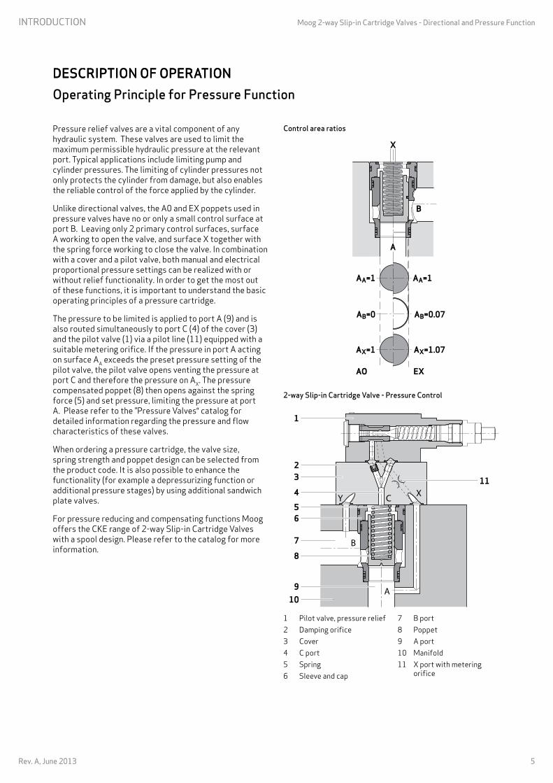


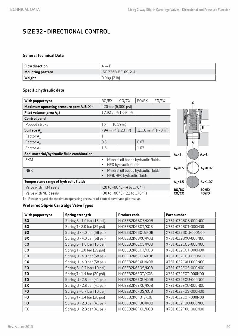


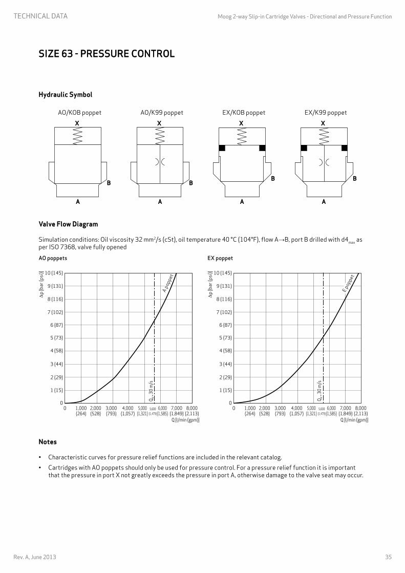
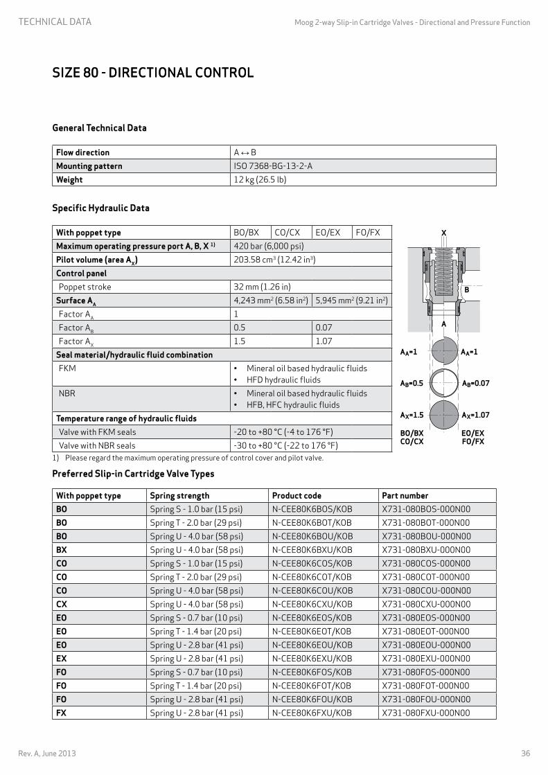


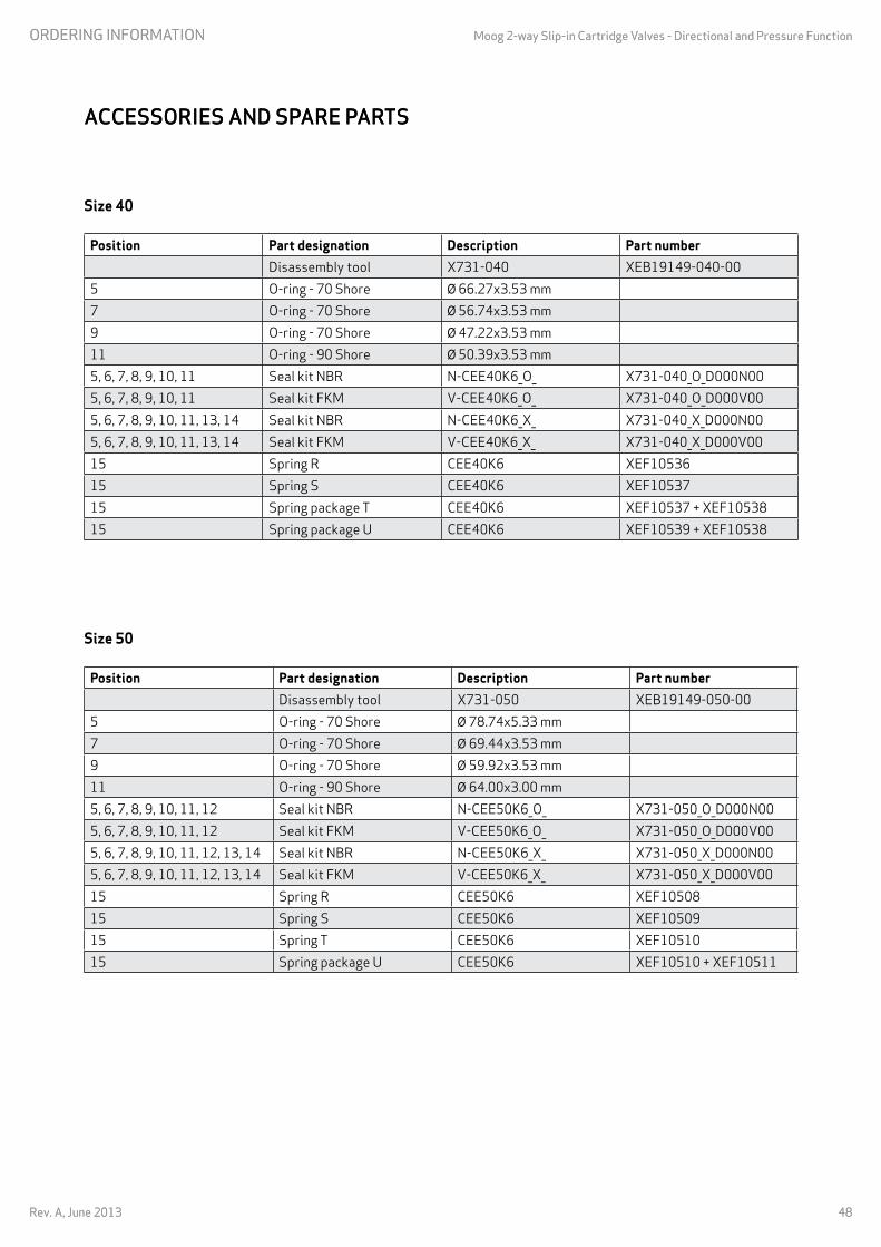


![Engineering science Optimal tests of slotted cartridge ...€¦ · and underground rock blasting engineering and so on [4-16]. Directional fracture blasting with slotted cartridge](https://static.documents.pub/doc/80x56/6062a8c6e431ce15844f83bc/engineering-science-optimal-tests-of-slotted-cartridge-and-underground-rock.jpg)


