• Accuracy Over Temperature:– Measured Error Using LUT: < 0.25ºC (-35ºC to
150ºC)– Measured Error Using First Order Transfer
Function: < 0.25ºC (15ºC to 100ºC)– Guaranteed Limits From LMT01 Datasheet
Using LUT: < 0.5 max. (–20ºC to 90ºC), 0.62max. (90ºC to 150ºC), < 0.7 max. (–50ºC to–20ºC)
Featured Applications• Building Automation: HVAC and Elevators
– Duct Temperature Measurement– Clip-on Temperature Sensor for Refrigerant
Copper Pipes– Ring Lug Surface Temperature Sensor– Temperature Sensor for Motor Protection– Compressor Discharge Temperature Monitor
• Digital Temperature Sensor Probe Assemblies• Factory Automation and Process Control
An IMPORTANT NOTICE at the end of this TI reference design addresses authorized use, intellectual property matters and otherimportant disclaimers and information.
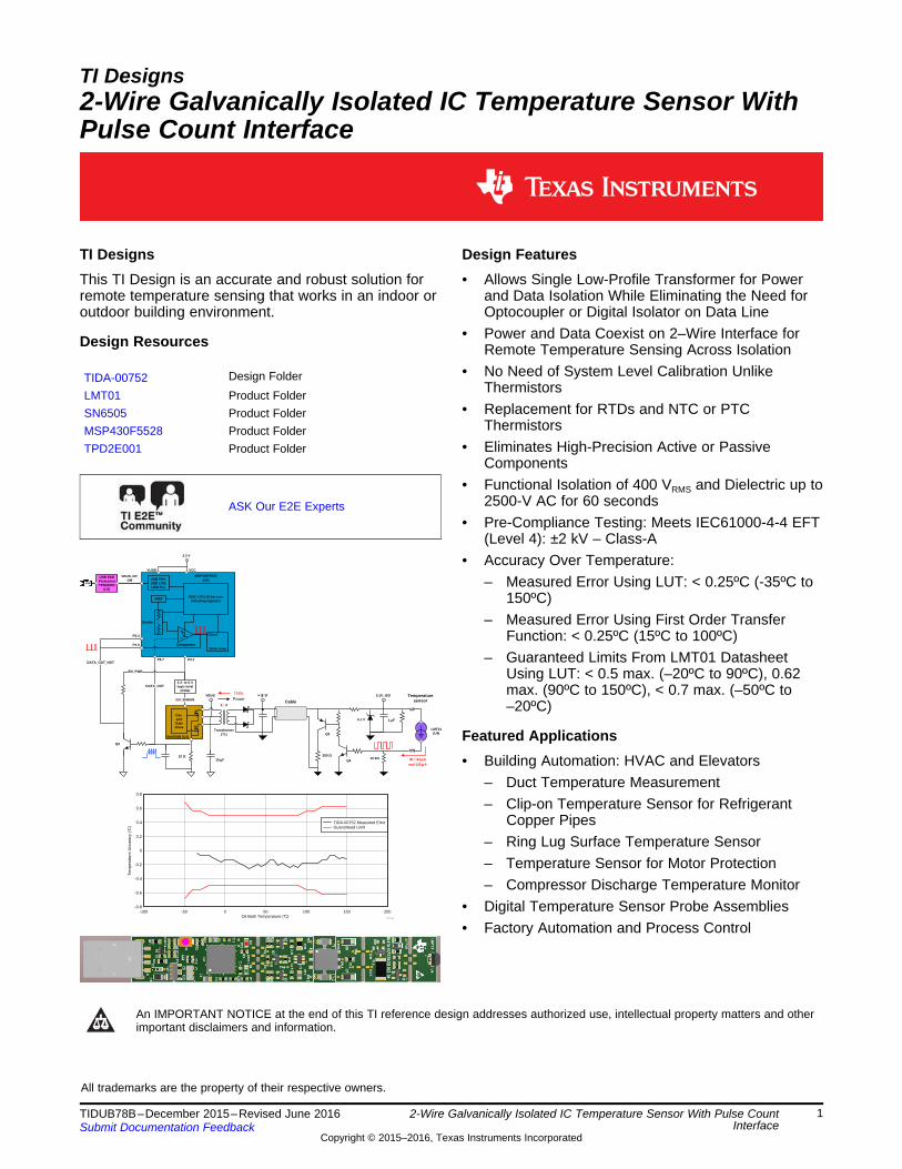
2-Wire Galvanically Isolated IC Temperature Sensor With Pulse CountInterface
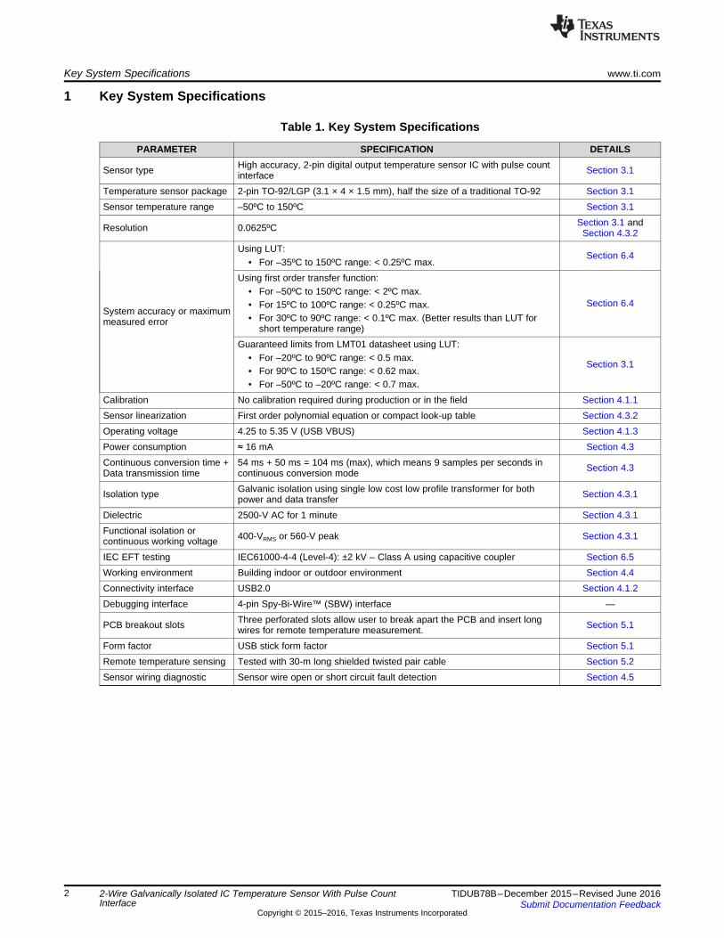
1 Key System Specifications
Table 1. Key System Specifications
PARAMETER SPECIFICATION DETAILS
Sensor type High accuracy, 2-pin digital output temperature sensor IC with pulse countinterface Section 3.1
Temperature sensor package 2-pin TO-92/LGP (3.1 × 4 × 1.5 mm), half the size of a traditional TO-92 Section 3.1Sensor temperature range –50ºC to 150ºC Section 3.1
Resolution 0.0625ºC Section 3.1 andSection 4.3.2
System accuracy or maximummeasured error
Using LUT:• For –35ºC to 150ºC range: < 0.25ºC max.
Section 6.4
Using first order transfer function:• For –50ºC to 150ºC range: < 2ºC max.• For 15ºC to 100ºC range: < 0.25ºC max.• For 30ºC to 90ºC range: < 0.1ºC max. (Better results than LUT for
short temperature range)
Section 6.4
Guaranteed limits from LMT01 datasheet using LUT:• For –20ºC to 90ºC range: < 0.5 max.• For 90ºC to 150ºC range: < 0.62 max.• For –50ºC to –20ºC range: < 0.7 max.
Section 3.1
Calibration No calibration required during production or in the field Section 4.1.1Sensor linearization First order polynomial equation or compact look-up table Section 4.3.2Operating voltage 4.25 to 5.35 V (USB VBUS) Section 4.1.3Power consumption ≈ 16 mA Section 4.3Continuous conversion time +Data transmission time
54 ms + 50 ms = 104 ms (max), which means 9 samples per seconds incontinuous conversion mode Section 4.3
Isolation type Galvanic isolation using single low cost low profile transformer for bothpower and data transfer Section 4.3.1
Dielectric 2500-V AC for 1 minute Section 4.3.1Functional isolation orcontinuous working voltage 400-VRMS or 560-V peak Section 4.3.1
IEC EFT testing IEC61000-4-4 (Level-4): ±2 kV – Class A using capacitive coupler Section 6.5Working environment Building indoor or outdoor environment Section 4.4Connectivity interface USB2.0 Section 4.1.2Debugging interface 4-pin Spy-Bi-Wire™ (SBW) interface —
PCB breakout slots Three perforated slots allow user to break apart the PCB and insert longwires for remote temperature measurement. Section 5.1
Form factor USB stick form factor Section 5.1Remote temperature sensing Tested with 30-m long shielded twisted pair cable Section 5.2Sensor wiring diagnostic Sensor wire open or short circuit fault detection Section 4.5
2-Wire Galvanically Isolated IC Temperature Sensor With Pulse CountInterface
2 System DescriptionAny temperature sensor connected to wires in a hostile environment can have its performance adverselyaffected by intense electromagnetic sources such as radio transmitters, induction heating systems, high-speed power switching elements, large solenoids, relays, motors with arching brushes, high AC voltageand current conductors, poorly grounded environments, interference from electrical transients, welders,lightning strikes, and so on. In such situations, lacking isolation impairs safety and induceselectromagnetic interference (EMI). Therefore, it becomes necessary to provide galvanic isolation betweenthe hazardous high voltage side and low voltage controller side. Electrically isolating the sensor providessafety and seamless voltage level shifting and eliminates ground noise, which ultimately enhancesperformance and reliability while making the system design more complicated because power and dataneed to be transferred across an isolation barrier. One would use one transformer for power isolation andanother transformer, optocoupler, or digital isolator for isolating the data, which increases complexity, cost,and footprint of the overall temperature measuring solution.
The 2-Wire Galvanically Isolated IC Temperature Sensor with Pulse Count Interface reference designprovides system designers the recommendations on how to design a new cost-effective, easy to use,small form factor, accurate, repeatable, and electrically isolated temperature measurement system basedon a new digital output IC temperature sensor. The new tiny 2-pin digital output IC temperature sensorwith a single wire pulse count interface enhances reliability and greatly simplifies the design of galvanicisolation architecture for sending both power and unidirectional data through a single low-cost, low-profiletransformer. The 2500-V AC breakdown barrier between the temperature sensor and power/data portspermit operation at high common-mode voltage enhancing safety and data integrity. For example, isolationprotects sensitive circuit components and human interface on the system side from potentially dangerousvoltage levels present on the field side. Isolation also eliminates ground loops that affect the measurementaccuracy. By simply following the recommendations provided, the user can realize remote temperaturesensing over long cables with lengths while achieving the performance as stated in the datasheetspecification. With a less than ±0.25°C maximum measured error and a ±0.7°C guaranteed error overtemperature range of -50°C to 150°C, functional isolation of 400 VRMS, and IEC61000-4-4 pre-compliancetesting, this design significantly reduces the design time of a high-accuracy temperature measurementsystem.
This reference design subsystem is highly differentiated over existing solutions by offering the followingbenefits:• Innovative approach allows single low-profile transformer for power and data isolation while eliminating
the need of optocoupler or digital isolator on data line• Eliminates high precision active or passive components like high PSRR LDO, ADC, instrumentation
amplifier, op amps, voltage reference, analog multiplexer, filters or better tolerance resistors, andcapacitors
• Power and data coexist on 2-wire interface for remote temperature sensing across isolation• Functional isolation of 400 VRMS and dielectric up to 2500-V AC for 60 seconds• No special power supply requirements; a simple open loop DC-DC power supply with high switching
frequency of 420 kHz that eliminates traditional bulky transformer• Eliminating complex calibration schemes, which saves cost during manufacturing and in after sales
servicing• Replacement for RTDs and NTC/PTC thermistors• Pre-compliance testing: Meets IEC61000-4-4 EFT (Level 4): ±2 kV – Class A with shielded twisted pair
cable• Sensor wire open or short circuit fault detection without any additional hardware• No measurement error due to jitter, propagation delay, and rise or fall time of isolated signal output• Extremely easy for system designers to get started with this approach and access market faster than
ever• With only one error source (the sensor itself), computation of error budget is pretty straightforward and
honest• Gets performance as stated in the datasheet specification
2-Wire Galvanically Isolated IC Temperature Sensor With Pulse CountInterface
At a high level, the 2-Wire Galvanically Isolated IC Temperature Sensor with Pulse Count InterfaceReference Design system consists of a high accuracy digital output IC temperature sensor, push-pulltransformer driver, system MCU, ESD protection device, and power management.
The overall system-level requirements for this reference design include:• Overall system accuracy: The system must be designed to meet the overall system error specification.
The maximum measured error must be less than ±0.5°C for a temperature range of 0°C to 100°C andless than 0.7°C for temperatures below 0°C and above 100°C.
• Remote sensor operation: In remote sensing applications, the costs are kept to a minimum by reducingthe amount of running copper over long distances. Therefore, the system must send temperaturemeasurements across isolation over long distances through 2-wire link without any loss of accuracydue to system wiring.
• Galvanic isolation: The isolation barrier must be designed to have a minimum dielectric withstandrating of 2000 VRMS for 60 seconds and a continuous working voltage of 250 VPEAK.
• Calibration and compensation: The system must require zero calibration during manufacturing and inthe field for quick and easy maintenance and minimizing amount of system downtime.
• Noise immunity: The system must be designed to meet IEC61000-4-4 EFT to provide robusttemperature monitoring with improved accuracy and noise immunity at reduced overall system cost.
• Less system complexity: The system must be simple and easy to use by minimizing number ofcomponents and software protocol overheads.
• Solution size: Entire solution needs to be in a small form factor design that can be easily installed.
This design guide addresses component selection, design theory, and test results of the TI Designsystem. The scope of this design guide gives system designers a head-start in integrating TI’s industrialtemperature sensor, push-pull transformer driver, system MCU, ESD protection device, and powermanagement technologies into their end-equipment systems. This reference design provides a completeset of downloadable documents such as a comprehensive design guide, schematic, Altium PCB layoutfiles, Gerber files, bill of materials (BOM), test results, firmware, and GUI that helps system designers inthe design and development of their end-equipment systems.
The following subsections describe the various blocks within the TI Design system and whatcharacteristics are most critical to best implement the corresponding function.
2-Wire Galvanically Isolated IC Temperature Sensor With Pulse CountInterface
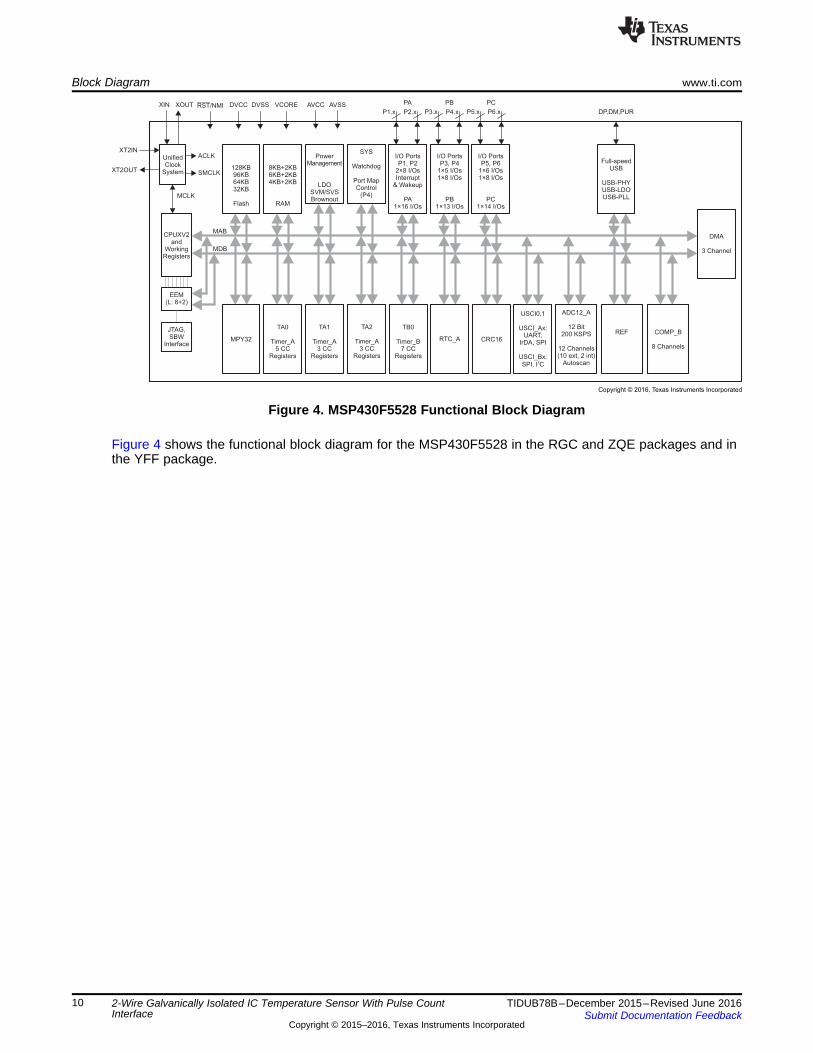
3 Block Diagram
Figure 1. Conceptual Schematic Diagram of 2-Wire Galvanically Isolated IC Temperature Sensor WithPulse Count Interface (TIDA-00752)
3.1 Highlighted ProductsThe 2-Wire Isolated Temperature Sensor Reference Design features the following devices:• LMT01: 0.5°C Accurate 2-Pin Digital Output Temperature Sensor with Pulse Count Interface• SN6505: Low-Noise 1-A Transformer Driver for Isolated Power Supplies• MSP430F5528: 16-Bit Ultra-Low-Power Microcontroller, 128KB Flash, 8KB RAM, USB, 12-Bit ADC, 2
USCIs and 32-Bit HW MPY• TPD2E001: Low-Capacitance 2-Channel ±15-kV ESD-Protection Array for High-Speed Data Interfaces
For more information on each of these devices, see their respective product folders at www.ti.com.
2-Wire Galvanically Isolated IC Temperature Sensor With Pulse CountInterface
The LMT01 is a high-accuracy, 2-pin temperature sensor with an easy-to-use pulse count interface, whichmakes it an ideal digital replacement for PTC or NTC thermistors both on and off board in automotive,industrial, and consumer markets. The LMT01 digital pulse count output and high accuracy over a widetemperature range allow pairing with any MCU without concern for integrated ADC quality or availabilitywhile minimizing software overhead. TI's LMT01 achieves flat ±0.5°C accuracy with very fine resolution(0.0625°C) over a wide temperature range of –20°C to 90°C without system calibration or hardware orsoftware compensation.
Unlike other digital IC temperature sensors, the LMT01's single wire interface is designed to directlyinterface with a GPIO or comparator input, thereby simplifying hardware implementation. Similarly, theLMT01's integrated EMI suppression and simple 2-pin architecture makes it ideal for onboard and off-board temperature sensing. The LMT01 offers all the simplicity of analog NTC or PTC thermistors with theadded benefits of a digital interface, wide specified performance, EMI immunity, and minimum processorresources.
2-Wire Galvanically Isolated IC Temperature Sensor With Pulse CountInterface
3.1.2 SN6505
Features• Push-pull driver for transformers• Wide input voltage range: 2.25 to 5.5 V• High output drive: 1 A at 5-V supply• Low RON: 0.25 Ω max at 4.5-V supply• Ultra-low EMI• Spread spectrum clocking• Precision internal oscillator options: 160 kHz
(SN6505A) and 420 kHz (SN6505B)• Synchronization of multiple devices with
external clock input• Slew-rate control• 1.7-A current limit• Low shutdown current: < 1 µA• Thermal shutdown• Wide temperature range: –55°C to 125°C• Small 6-pin SOT23/DBV package• Soft start to reduce inrush current
Applications• Isolated power supply for CAN, RS-485,
RS-422, RS-232, SPI, I2C, andlow-power LAN
• Low-noise isolated USB supplies• Process control• Telecom supplies• Radio supplies• Medical instruments• Distributed supplies• Precision instruments• Low-noise filament supplies
Figure 3. SN6505 Functional Block Diagram
The SN6505 is a transformer driver designed for low-cost, small form-factor, isolated DC-DC convertersutilizing the push-pull topology. The device includes an oscillator that feeds a gate-drive circuit. The gate-drive, comprising a frequency divider and a break-before-make (BBM) logic, provides two complementaryoutput signals which alternately turn the two output transistors on and off.
The output frequency of the oscillator is divided down by two . A subsequent break-before-make logicinserts a dead-time between the high-pulses of the two signals. Before either one of the gates can assumelogic high, the BBM logic ensures a short time period during which both signals are low and bothtransistors are high-impedance. This short period, is required to avoid shorting out both ends of theprimary. The resulting output signals, present the gate-drive signals for the output transistors.
• IO capacitance: 1.5 pF (typical)• Low leakage current: 1 nA (max)• Low supply current: 1 nA• 0.9- to 5.5-V supply voltage range• Space-saving DRL, DRY, and QFN package
options• Alternate 3-, 4-, and 6-channel options
available: TPD3E001, TPD4E001,TPD6E001
Applications• USB 2.0• Ethernet• FireWire™• LVDS• SVGA video connections• Glucose meters• Medical imaging
Figure 5. TPD2E001 Functional Block Diagram
The TPD2E001 is a uni-directional ESD protection device with low capacitance. The device is constructedwith a central ESD clamp that features two hiding diodes per line to reduce the capacitive loading. Thiscentral ESD clamp is also connected to VCC to provide protection for the VCC line. Each IO line is rated todissipate ESD strikes above the maximum level specified in the IEC 61000-4-2 level 4 internationalstandard. The TPD2E001's low loading capacitance makes it ideal for protection high-speed signalterminals.
2-Wire Galvanically Isolated IC Temperature Sensor With Pulse CountInterface
4 System Design Theory and Considerations
4.1 Component SelectionBefore starting the circuit design and layout of the actual system, this reference design carefully examineall the captured system level requirements and features. Then, use a top-down approach to translatethese system level requirements into subsystem or component level requirements that helps in selectingthe right set of devices. Some of the subsystem or component level requirements are as follows.
4.1.1 Selecting a Temperature SensorSelecting a temperature sensor is a critical part in the design of any temperature measurement systembecause the reliability, stability, and accuracy of the entire system cannot be better than that of thesensing element. Selecting a temperature sensor is also very important because it decides the overallsystem architecture and greatly influences the selection of other supporting devices. The right temperaturesensor depends upon various factors such as operating temperature range, accuracy, linearity, sensitivity,interchangeability, repeatability, stability and drift, corrosion and contamination effects, lead-wireresistance, cost, power consumption, size, mounting, design cycle time, and ease of designing thenecessary support circuit. From a system level standpoint, the temperature sensor must satisfy thefollowing requirements:• The temperature sensor must have a minimum operating temperature range of –40°C to 125°C.• The temperature sensor must simplify the design of galvanic isolation architecture.• The temperature sensor must be available in a smaller package, which makes it easy to mount the
sensor inside sealed metallic housing or lug to produce standard or custom probe assemblies.• The temperature sensor must not have more than two pins that reduce the amount of copper running
over long distances in wire-limited or remote-sensing applications.• The temperature sensor’s lead-wire resistance must not introduce significant errors.• The temperature sensor must have very little self-heating effect.• The temperature sensor must have superior noise immunity.
2-Wire Galvanically Isolated IC Temperature Sensor With Pulse CountInterface
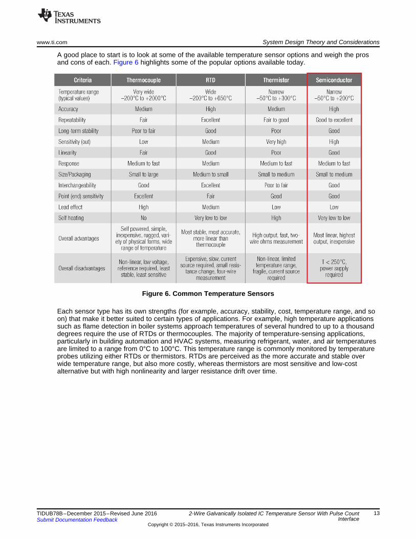
A good place to start is to look at some of the available temperature sensor options and weigh the prosand cons of each. Figure 6 highlights some of the popular options available today.
Figure 6. Common Temperature Sensors
Each sensor type has its own strengths (for example, accuracy, stability, cost, temperature range, and soon) that make it better suited to certain types of applications. For example, high temperature applicationssuch as flame detection in boiler systems approach temperatures of several hundred to up to a thousanddegrees require the use of RTDs or thermocouples. The majority of temperature-sensing applications,particularly in building automation and HVAC systems, measuring refrigerant, water, and air temperaturesare limited to a range from 0°C to 100°C. This temperature range is commonly monitored by temperatureprobes utilizing either RTDs or thermistors. RTDs are perceived as the more accurate and stable overwide temperature range, but also more costly, whereas thermistors are most sensitive and low-costalternative but with high nonlinearity and larger resistance drift over time.
2-Wire Galvanically Isolated IC Temperature Sensor With Pulse CountInterface
From Figure 6, it is quite evident that thermocouple, RTD, thermistor or IC temperature sensor-basedsolutions have a number of design drawbacks such as the accumulated error of all the components,power consumption, linearity, quantization noise, calibration, operating temperature range, complexity,board area, and production cost. Each temperature sensor has its own advantages and disadvantages.Therefore, this reference design uses a new tiny LMT01 (see Figure 7) to address most of these designdrawbacks. Standalone IC temperature sensors have rarely been considered for implementation intosensor probes or assemblies due to their larger geometries. However, designers exploit the processtechnology of these IC temperature sensors to everyone’s advantage. The LMT01 is a completetemperature data-acquisition system on a monolithic silicon chip. A silicon-based sensor, internal voltagereference, and delta-sigma ADC all fit in a 2-pin (power and ground) TO-92/LGP package (half the size oftraditional TO-92) while delivering unmatched value-for-performance such as high accuracy over time andtemperature, very low power consumption, and simple design-in capability. Integrating the wholetemperature-to-digital signal chain on a single chip, therefore, saves space, design time, and money. Now,system designers need not worry about power supply noise, complex linearization algorithms, cold-junction compensation, comparators, additional ADCs, voltage references, and so on. Unlike analogtemperature sensors, the pulse count interface of the LMT01 offers superior noise immunity especially inremote sensing applications.
Figure 7. Parametric Table for Selecting Temperature Sensor
4.1.2 Selecting an Ultra-Low Power Microcontroller (MCU)The 2-Wire Galvanically Isolated IC Temperature Sensor with Pulse Count Interface reference design hasrelatively few requirements for the MCU. This TI Design reproduces the LMT01 pulses on the MCU sideacross isolation barrier that needs to be counted by the MCU to know the temperature. There are variousmethods for pulse counting utilizing common resources such as GPIOs with interrupt capability, timers,and comparators, which are available on virtually any low cost MCU. In addition, this TI Design needsUSB connectivity with a PC or laptop for easy transfer of data to GUI that aids in testing anddemonstration.
Because this TI Design is meant to demonstrate TI technology, the USB-equipped MSP430F5528 devicewas selected as the system MCU. This device fulfills all the requirements of this TI Design subsystem, andfeatures ultra-low power performance.
2-Wire Galvanically Isolated IC Temperature Sensor With Pulse CountInterface
4.1.3 Selecting a Power ConfigurationThis TI Design has few power supply requirements. The design’s hardware is configured to be poweredfrom a standard USB host that provides nominal voltage of 5 V over the USB cable, called VBUS. TheUSB VBUS may vary from 4.25 to 5.35 V. Because this design will be permanently tethered to the USBhost, this eliminates the need for a separate local power supply. This design requires a regulated non-isolated 3.3-V voltage rail for all components on the low-voltage side and an unregulated isolated DC/DCconverter generating 8 V on the field side.
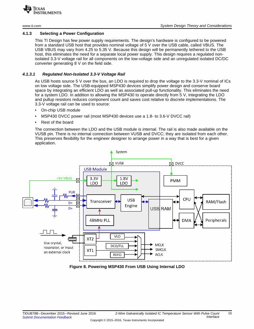
4.1.3.1 Regulated Non-Isolated 3.3-V Voltage RailAs USB hosts source 5 V over the bus, an LDO is required to drop the voltage to the 3.3-V nominal of ICson low voltage side. The USB-equipped MSP430 devices simplify power design and conserve boardspace by integrating an efficient LDO as well as associated pull-up functionality. This eliminates the needfor a system LDO. In addition to allowing the MSP430 to operate directly from 5 V, integrating the LDOand pullup resistors reduces component count and saves cost relative to discrete implementations. The3.3-V voltage rail can be used to source:• On-chip USB module• MSP430 DVCC power rail (most MSP430 devices use a 1.8- to 3.6-V DVCC rail)• Rest of the board
The connection between the LDO and the USB module is internal. The rail is also made available on theVUSB pin. There is no internal connection between VUSB and DVCC; they are isolated from each other.This preserves flexibility for the engineer designer to arrange power in a way that is best for a givenapplication.
Figure 8. Powering MSP430 From USB Using Internal LDO
2-Wire Galvanically Isolated IC Temperature Sensor With Pulse CountInterface
4.1.3.2 Unregulated Isolated 8-V Voltage RailThis is an excellent example how the LMT01 takes away all the pain of building an accurate isolatedtemperature measurement system, while relaxing the requirements on other supporting blocks. Becausethe LMT01 has an integrated regulator that provides a stable power supply to its internal circuitry andoperates on a floating 2- to 5.5-V (VP–VN) power supply that can vary greatly, unlike other noise-sensitivecircuitry, the LMT01 enforces no special requirements such as tight regulation under dynamic loadconditions, low noise, and low ripple when designing the isolated power supply.
Some of the basic requirements for unregulated isolated power supply are:• Input voltage: 5-V nominal UBS VBUS (4.25 to 5.35 V)• Ramp rate faster than 2.5 ms• Smaller magnetic component• Simple, low-cost and area-compliant approach• Enable and disable feature to put power supply in shutdown mode• Very low shutdown current
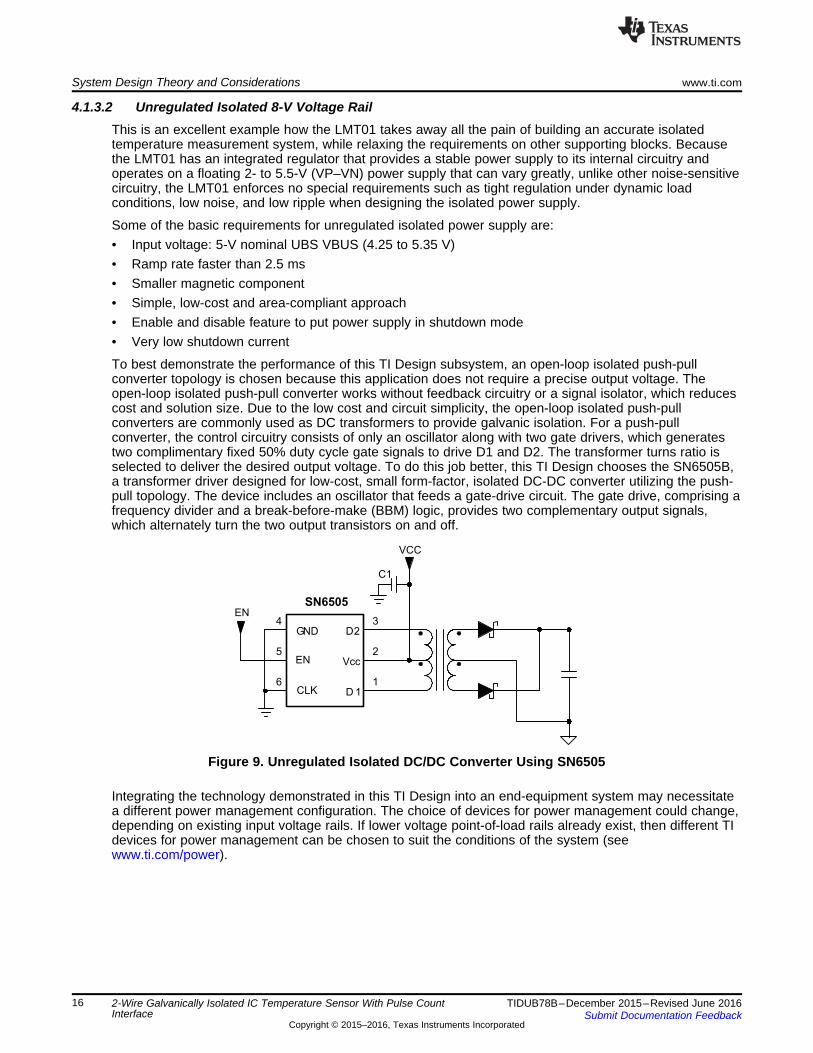
To best demonstrate the performance of this TI Design subsystem, an open-loop isolated push-pullconverter topology is chosen because this application does not require a precise output voltage. Theopen-loop isolated push-pull converter works without feedback circuitry or a signal isolator, which reducescost and solution size. Due to the low cost and circuit simplicity, the open-loop isolated push-pullconverters are commonly used as DC transformers to provide galvanic isolation. For a push-pullconverter, the control circuitry consists of only an oscillator along with two gate drivers, which generatestwo complimentary fixed 50% duty cycle gate signals to drive D1 and D2. The transformer turns ratio isselected to deliver the desired output voltage. To do this job better, this TI Design chooses the SN6505B,a transformer driver designed for low-cost, small form-factor, isolated DC-DC converter utilizing the push-pull topology. The device includes an oscillator that feeds a gate-drive circuit. The gate drive, comprising afrequency divider and a break-before-make (BBM) logic, provides two complementary output signals,which alternately turn the two output transistors on and off.
Figure 9. Unregulated Isolated DC/DC Converter Using SN6505
Integrating the technology demonstrated in this TI Design into an end-equipment system may necessitatea different power management configuration. The choice of devices for power management could change,depending on existing input voltage rails. If lower voltage point-of-load rails already exist, then different TIdevices for power management can be chosen to suit the conditions of the system (seewww.ti.com/power).
2-Wire Galvanically Isolated IC Temperature Sensor With Pulse CountInterface
4.1.4 EMI ProtectionThis TI Design has robust protection against electromagnetic interference (EMI) because USB allows theapplication to have an open connection to the external environment, which could expose the entire systemto ESD. Therefore, it is recommended to increase ESD protection on the USB DP, DM, and VBUS lines.This protection should be located as close as possible to the USB connector to reduce the potentialdischarge path and reduce discharge propagation within the entire system.
This TI Design uses the TPD2E001, a low-capacitance 2-channel ESD protection optimized for high speedapplications help save design time. TPD2E001 clean up the application around the interface and maximizeprotection of system chips while minimizing the impact on signal integrity.
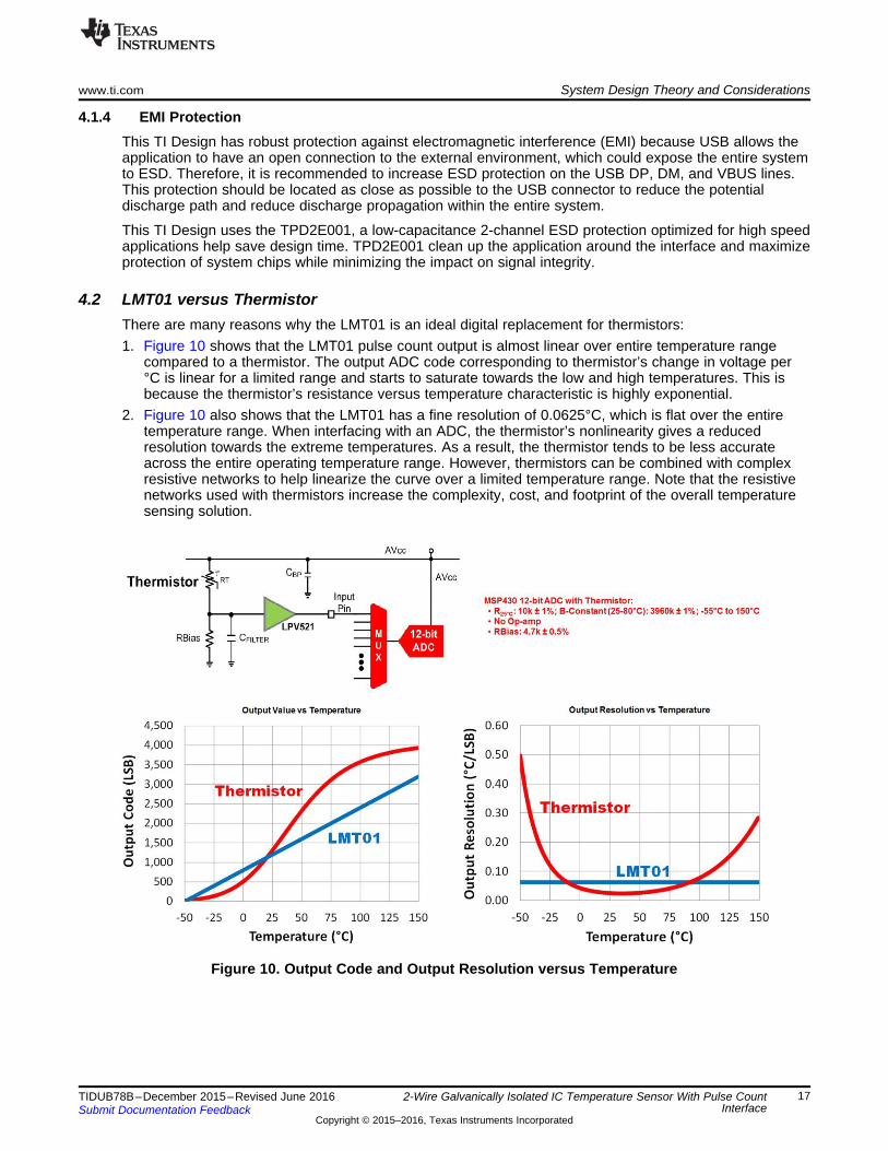
4.2 LMT01 versus ThermistorThere are many reasons why the LMT01 is an ideal digital replacement for thermistors:1. Figure 10 shows that the LMT01 pulse count output is almost linear over entire temperature range
compared to a thermistor. The output ADC code corresponding to thermistor’s change in voltage per°C is linear for a limited range and starts to saturate towards the low and high temperatures. This isbecause the thermistor’s resistance versus temperature characteristic is highly exponential.
2. Figure 10 also shows that the LMT01 has a fine resolution of 0.0625°C, which is flat over the entiretemperature range. When interfacing with an ADC, the thermistor’s nonlinearity gives a reducedresolution towards the extreme temperatures. As a result, the thermistor tends to be less accurateacross the entire operating temperature range. However, thermistors can be combined with complexresistive networks to help linearize the curve over a limited temperature range. Note that the resistivenetworks used with thermistors increase the complexity, cost, and footprint of the overall temperaturesensing solution.
Figure 10. Output Code and Output Resolution versus Temperature
2-Wire Galvanically Isolated IC Temperature Sensor With Pulse CountInterface
3. Figure 11 shows that the LMT01’s consistent low power consumption across temperature minimizesself-heating and system power, further easing the design challenge of temperature monitoring thatmost of the system engineers encounter when using thermistors. Thermistors have a supply currentthat varies greatly over temperature. As temperature increases, the NTC thermistor’s resistancedecreases; this causes the current through the voltage divider network to increase. When the current ishigh, NTC thermistors can self-heat above the ambient temperature of the environment, resulting intemperature errors.
Figure 11. Supply Current and Self Heating versus Temperature
4. Another thing to consider when deciding to use a thermistor is the output impedance. The outputimpedance of a thermistor is generally higher and varies depending on the temperature. When usingan ADC with a thermistor, ensure that the ADC can handle thermistor’s source impedance. In somecases, a buffer may be required whereas an easy connection of the LMT01 with the MCU requiresminimum components (for example, a simple 5% tolerance resistor).
Figure 12. Typical Thermistor and LMT01-Based Circuits
2-Wire Galvanically Isolated IC Temperature Sensor With Pulse CountInterface
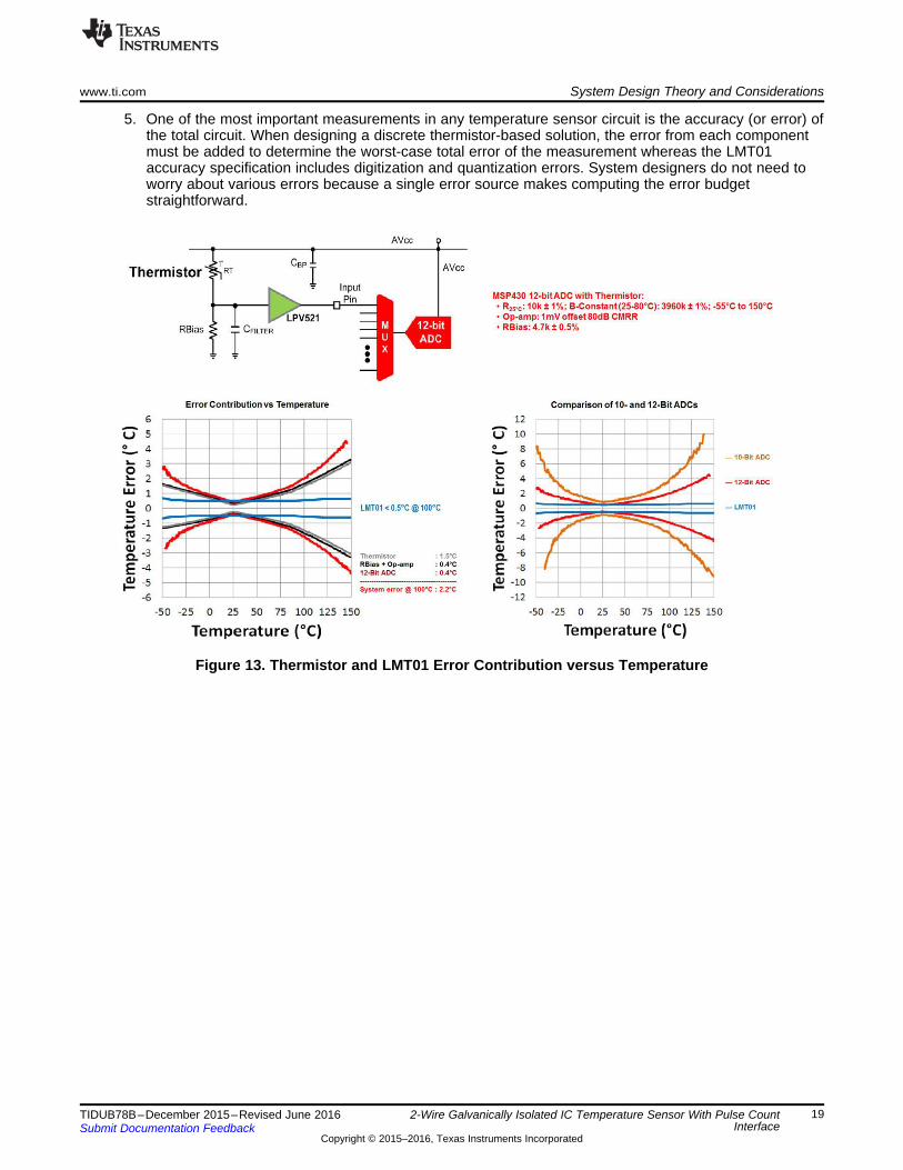
5. One of the most important measurements in any temperature sensor circuit is the accuracy (or error) ofthe total circuit. When designing a discrete thermistor-based solution, the error from each componentmust be added to determine the worst-case total error of the measurement whereas the LMT01accuracy specification includes digitization and quantization errors. System designers do not need toworry about various errors because a single error source makes computing the error budgetstraightforward.
Figure 13. Thermistor and LMT01 Error Contribution versus Temperature
2-Wire Galvanically Isolated IC Temperature Sensor With Pulse CountInterface
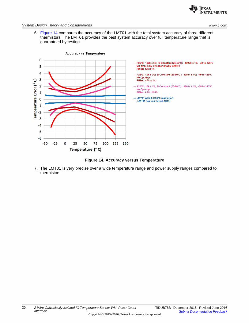
6. Figure 14 compares the accuracy of the LMT01 with the total system accuracy of three differentthermistors. The LMT01 provides the best system accuracy over full temperature range that isguaranteed by testing.
Figure 14. Accuracy versus Temperature
7. The LMT01 is very precise over a wide temperature range and power supply ranges compared tothermistors.
2-Wire Galvanically Isolated IC Temperature Sensor With Pulse CountInterface
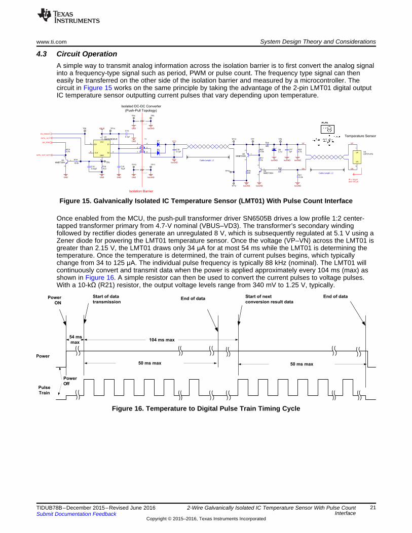
4.3 Circuit OperationA simple way to transmit analog information across the isolation barrier is to first convert the analog signalinto a frequency-type signal such as period, PWM or pulse count. The frequency type signal can theneasily be transferred on the other side of the isolation barrier and measured by a microcontroller. Thecircuit in Figure 15 works on the same principle by taking the advantage of the 2-pin LMT01 digital outputIC temperature sensor outputting current pulses that vary depending upon temperature.
Figure 15. Galvanically Isolated IC Temperature Sensor (LMT01) With Pulse Count Interface
Once enabled from the MCU, the push-pull transformer driver SN6505B drives a low profile 1:2 center-tapped transformer primary from 4.7-V nominal (VBUS–VD3). The transformer’s secondary windingfollowed by rectifier diodes generate an unregulated 8 V, which is subsequently regulated at 5.1 V using aZener diode for powering the LMT01 temperature sensor. Once the voltage (VP–VN) across the LMT01 isgreater than 2.15 V, the LMT01 draws only 34 μA for at most 54 ms while the LMT01 is determining thetemperature. Once the temperature is determined, the train of current pulses begins, which typicallychange from 34 to 125 μA. The individual pulse frequency is typically 88 kHz (nominal). The LMT01 willcontinuously convert and transmit data when the power is applied approximately every 104 ms (max) asshown in Figure 16. A simple resistor can then be used to convert the current pulses to voltage pulses.With a 10-kΩ (R21) resistor, the output voltage levels range from 340 mV to 1.25 V, typically.
Figure 16. Temperature to Digital Pulse Train Timing Cycle
2-Wire Galvanically Isolated IC Temperature Sensor With Pulse CountInterface
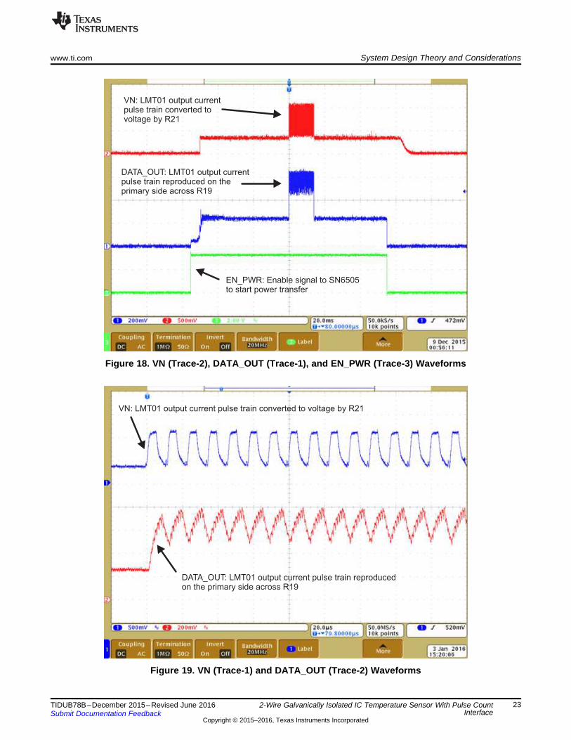
The output voltage pulse train then drives the base of an NPN transistor (Q4) with a 22-kΩ (R22) baseresistor. The Q4 in-turn controls the on-off of PNP transistor (Q5). This means the LMT01 temperature’soutput indirectly connects or disconnects a 249-Ω (R16) load resistor to the unregulated 8-V supply rail.Therefore, the 249-Ω load resistor suddenly demands a high current during a positive half cycle and veryless current during a negative half cycle of the temperature sensor’s output. The filter capacitor (C16) atrectifier output on secondary side was intentionally kept very small that places more demands on the inputbulk capacitor (C19) at the center tap of the primary for supplying large currents during the fast switchingtransients on the secondary side due to the LMT01 temperature sensor’s output. This makes the pulsefrequency of 88 kHz visible on the primary side in the form of supply current, which is then sensed byplacing a small shunt resistor (R19) in the ground return path of SN6505B as shown in Figure 17 andFigure 18. The output (DATA_OUT) from R19 and C18 then drives the base of an NPN transistor (Q3)with a 10-kΩ (R18) base resistor to generate a level shifted output (DATA_OUT_NOT). Figure 20 showsthe DATA_OUT and DATA_OUT_NOT waveforms. This configuration successfully reproduces thesensor’s output on the primary side across isolation as shown in Figure 19. The value of the R19 shuntresistor was chosen such that circuit quiescent current during sensor’s conversion time does not turn onQ3. The outputs DATA_OUT and DATA_OUT_NOT are then fed to P1.0/TA0CLK/ACLK, P2.4/TA2.1, andP6.7/CB7/A7 pins of the MSP430 for implementing different pulse counting methods utilizing theMSP430’s resources such as GPIO with interrupt, comparator, and timers. This innovative approachisolates the temperature sensor utilizing a single transformer for simultaneous transfer of both power anddata across the isolation barrier. The entire circuit draws about 16 mA of average current from VBUS tooperate.
Figure 17. LMT01 Output Current Pulse Train Reproduced on Primary Side Across R19
2-Wire Galvanically Isolated IC Temperature Sensor With Pulse CountInterface
Figure 20. DATA_OUT (Trace-1), EN_PWR (Trace-2), and DATA_OUT_NOT (Trace-3) Waveforms
4.3.1 Transformer SelectionTo prevent a transformer from saturation its V-t product must be greater than the maximum V-t productapplied by the SN6505. Therefore, the transformer’s minimum V-t product is determined throughEquation 1:
(1)
where• VIN(max) is the maximum input voltage to the SN6505B• fSW(min) is the minimum switching frequency of the SN6505B
The transformer selected for this TI Design is 760390015 from Wurth Electronics, which provides V-tproduct of 11 Vμs with significantly reduced footprint of 10.05 × 6.73 × 4.19 mm. The selected transformerhas a working voltage of 400 VRMS and dielectric-withstand voltage of 2500-V AC, which is more thanenough for this design.
2-Wire Galvanically Isolated IC Temperature Sensor With Pulse CountInterface
4.3.2 Sensor LinearizationThere are two different methods of converting the pulse count (PC) to a temperature value, first using afirst-order transfer function and second using the datasheet’s look-up table. This reference designdemonstrates the performance using both options.
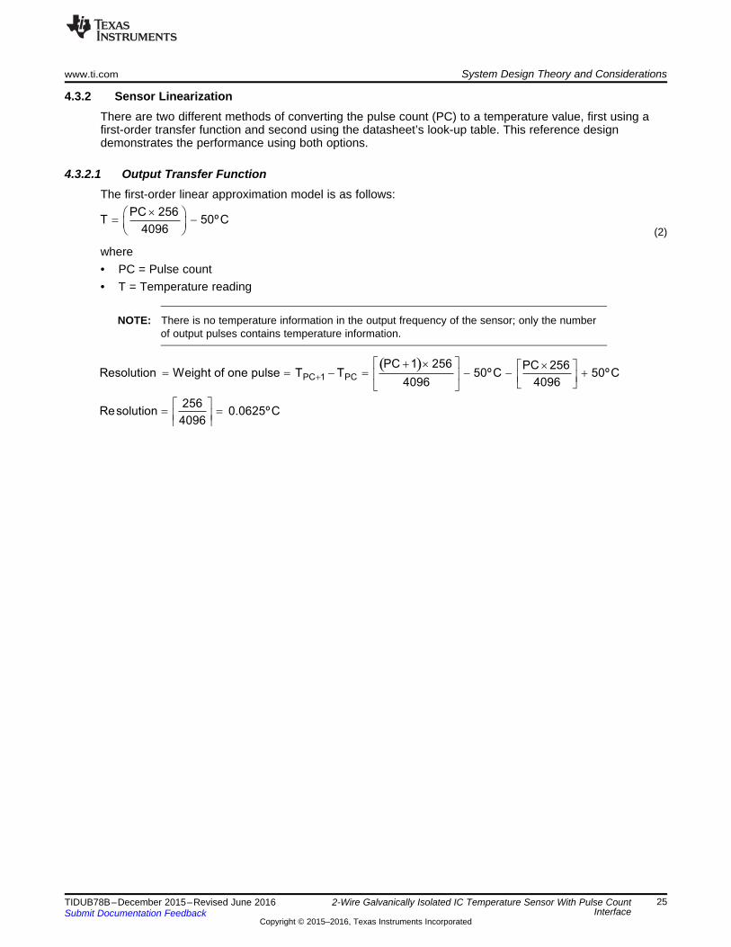
4.3.2.1 Output Transfer FunctionThe first-order linear approximation model is as follows:
(2)
where• PC = Pulse count• T = Temperature reading
NOTE: There is no temperature information in the output frequency of the sensor; only the numberof output pulses contains temperature information.
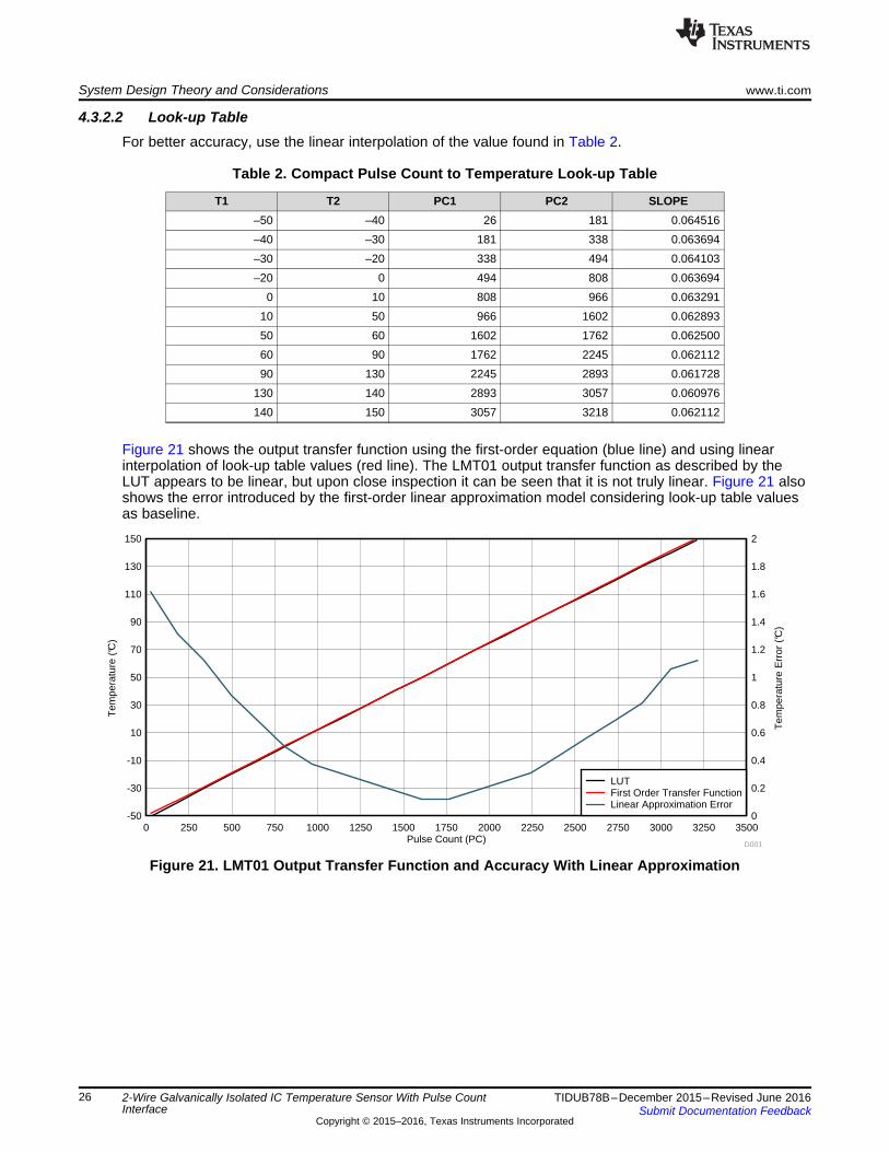
Figure 21 shows the output transfer function using the first-order equation (blue line) and using linearinterpolation of look-up table values (red line). The LMT01 output transfer function as described by theLUT appears to be linear, but upon close inspection it can be seen that it is not truly linear. Figure 21 alsoshows the error introduced by the first-order linear approximation model considering look-up table valuesas baseline.
Figure 21. LMT01 Output Transfer Function and Accuracy With Linear Approximation
2-Wire Galvanically Isolated IC Temperature Sensor With Pulse CountInterface
4.3.3 Self-HeatingMore or less, all temperature sensors exhibit a phenomenon known as self-heating. The internal self-heating is a byproduct of electrical current flow in the electronic device during its operation. Dissipatingpower in the temperature sensor causes its temperature to rise above that of the surroundingenvironment. Any difference between the temperature of the sensor and the environment produces atemperature measurement error or uncertainty. Minimizing the temperature measurement uncertainty thusrequires balancing the uncertainties due to self-heating. The thermal resistance junction-to-ambient (RθJA)is the parameter used to calculate the rise of a device junction temperature (self-heating) due to itsaverage power dissipation. The average power dissipation of the LMT01 is dependent on the temperatureit is transmitting as it affects the output pulse count and the voltage across the device. Equation 3 is usedto calculate the self-heating in the LMT01's die temperature (TSH).
(3)
where• TSH is the ambient temperature• IOL and IOH are the output low and high current level, respectively• VCONV is the voltage across the LMT01 during conversion• VDATA is the voltage across the LMT01 during data transmission• tCONV is the conversion rate• tDATA is the data transmission time• PC is the output pulse count• RθJA is the junction to ambient package thermal resistance
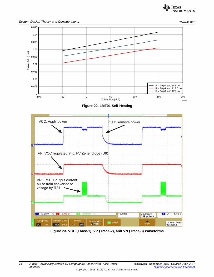
With a temperature range of –50°C to 150°C, a VCONV of 4.76 V was used for the self-heating calculation.As can be seen in the curve in Figure 22, the average self-heating changes linearly over temperaturebecause the number of pulses increases with temperature. A negligible self-heating of about 42 m°C isobserved at 150°C with continuous conversions. If temperature readings are not required as frequently asevery 100 ms, self-heating can be minimized by shutting down power to the part periodically thus loweringthe average power dissipation as shown in Figure 23. Be sure to use a power down wait time of 50 ms, atminimum, before the device is turned on again.
2-Wire Galvanically Isolated IC Temperature Sensor With Pulse CountInterface
4.4 Wired Temperature Sensor Probes Using LMT01Remote temperature sensors require some form of packaging to allow them to withstand conditions suchas rough handling, vibration and moisture. Many temperature sensors are so fragile that even normalinstallation can be harmful for them. The main purpose of the housing is to protect the sensing element. Arugged, moisture resistant temperature sensing probes and assemblies have proven extremely effective inhigh moisture environments and quite commonly used in HVAC applications such as chillers, heat pumps,packaged terminal air conditioners (PTACs), boilers, furnaces, air handlers, zone controls, and many otherheating and cooling products. Its low cost, tiny package (TO-92/LGP), and 2-pin interface make theLMT01 IC temperature sensor a best choice for wired-sensor probe assemblies benefitting in buildingindoor and outdoor temperature measurement applications. Figure 24 shows some of the wired-sensorprobe assemblies, which were built using the LMT01 having form-factors fully compatible with RTD orthermistor-based temperature probes.
Figure 24. LMT01 IC Temperature Sensor Based Wired-Probe Assemblies
4.5 Sensor Wiring DiagnosticsKnowing the amount of current being delivered to a sensor can be useful in wiring fault detection andprotection. The current being delivered can be easily monitored by adding a sense resistor in series withthe circuit. By nature, this circuit already uses a sense resistor in the primary circuit for its normaloperation. This capability can also be used to detect open or short circuits caused by wiring or connectorfailures and can timely trigger a preventive action. Therefore, this novel circuit allows simple and reliablediagnostics of system wiring faults without requiring any additional hardware.
The default firmware does not support the sensor diagnostic feature. However, by writing a small code ontop of your application as per directions in this section can perform continuous on-line sensor diagnosiswithout running a separate diagnostic cycle. This may save production costs, and hours of troubleshootingtime, by letting you know when a problem occurs and its type.
2-Wire Galvanically Isolated IC Temperature Sensor With Pulse CountInterface
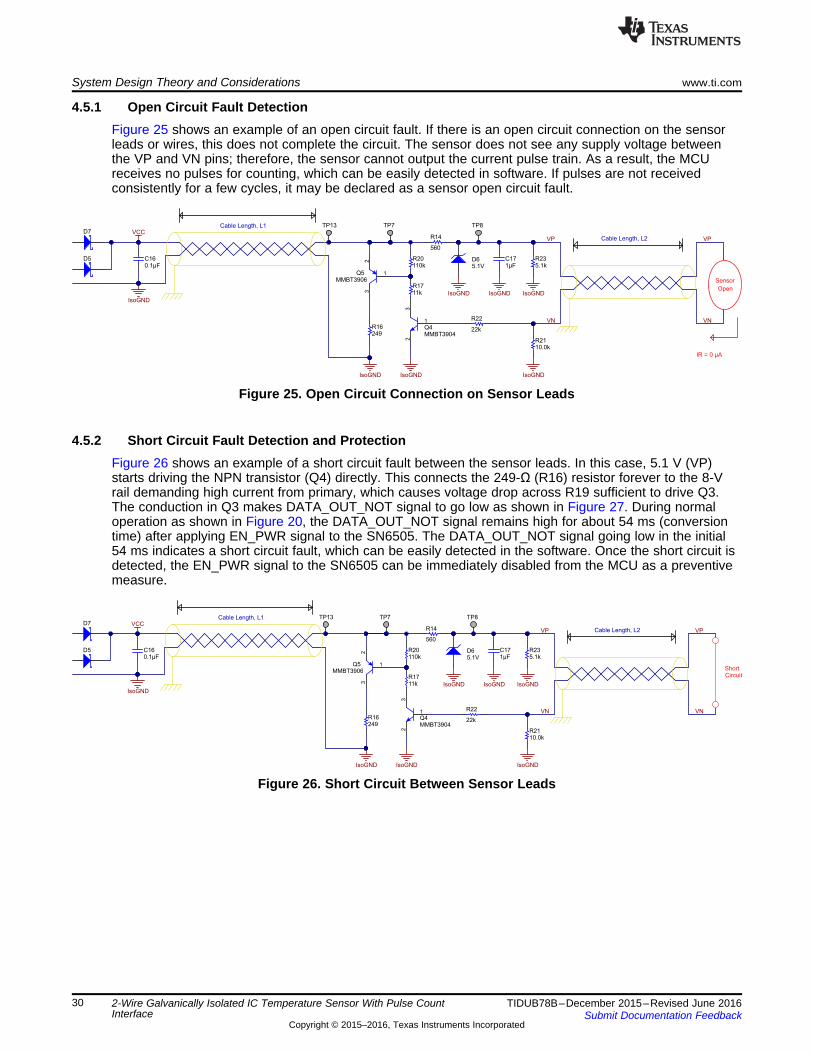
4.5.1 Open Circuit Fault DetectionFigure 25 shows an example of an open circuit fault. If there is an open circuit connection on the sensorleads or wires, this does not complete the circuit. The sensor does not see any supply voltage betweenthe VP and VN pins; therefore, the sensor cannot output the current pulse train. As a result, the MCUreceives no pulses for counting, which can be easily detected in software. If pulses are not receivedconsistently for a few cycles, it may be declared as a sensor open circuit fault.
Figure 25. Open Circuit Connection on Sensor Leads
4.5.2 Short Circuit Fault Detection and ProtectionFigure 26 shows an example of a short circuit fault between the sensor leads. In this case, 5.1 V (VP)starts driving the NPN transistor (Q4) directly. This connects the 249-Ω (R16) resistor forever to the 8-Vrail demanding high current from primary, which causes voltage drop across R19 sufficient to drive Q3.The conduction in Q3 makes DATA_OUT_NOT signal to go low as shown in Figure 27. During normaloperation as shown in Figure 20, the DATA_OUT_NOT signal remains high for about 54 ms (conversiontime) after applying EN_PWR signal to the SN6505. The DATA_OUT_NOT signal going low in the initial54 ms indicates a short circuit fault, which can be easily detected in the software. Once the short circuit isdetected, the EN_PWR signal to the SN6505 can be immediately disabled from the MCU as a preventivemeasure.
2-Wire Galvanically Isolated IC Temperature Sensor With Pulse CountInterface
Figure 27. Circuit Behavior During Short Circuit Fault Between Sensor Leads
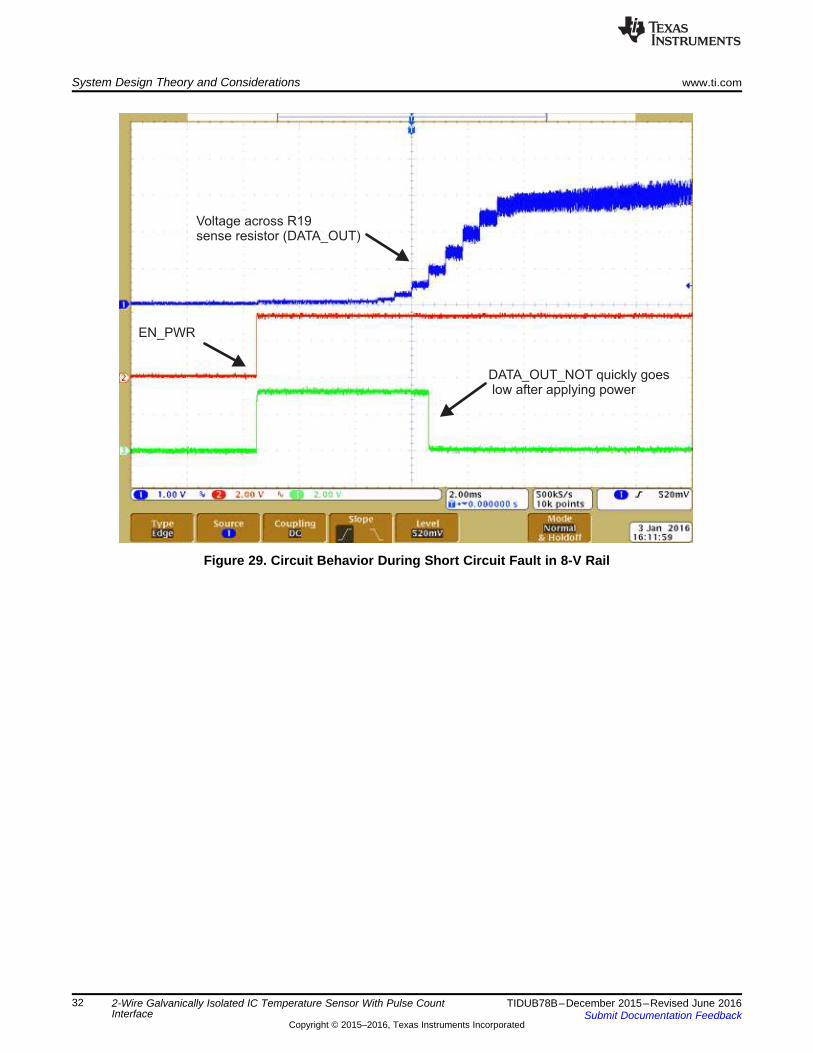
Figure 28 shows another example of short circuit in the 8-V rail wiring. In this situation, a dead short in the8-V rail suddenly puts an excessive current demand on the primary. The SN6505 has a current limitingfunction, which gets activated at 1.7 A; this is perhaps too high for an end-equipment application. Thevoltage drop across R19 starts ramp-up. As soon as this voltage goes slightly higher than 0.7 V, theconduction in Q3 starts, which immediately pulls DATA_OUT_NOT signal low. All this happens muchbefore the short circuit current shoots to a very high value and triggers the SN6505 current limitingfunction. Just like the previous situation, the DATA_OUT_NOT signal going low in the initial 54 msindicates a short circuit fault, which can be easily detected in the software. Once the short circuit isdetected, the EN_PWR signal to the SN6505 can be immediately disabled from the MCU as a preventivemeasure.
2-Wire Galvanically Isolated IC Temperature Sensor With Pulse CountInterface
5 Getting Started
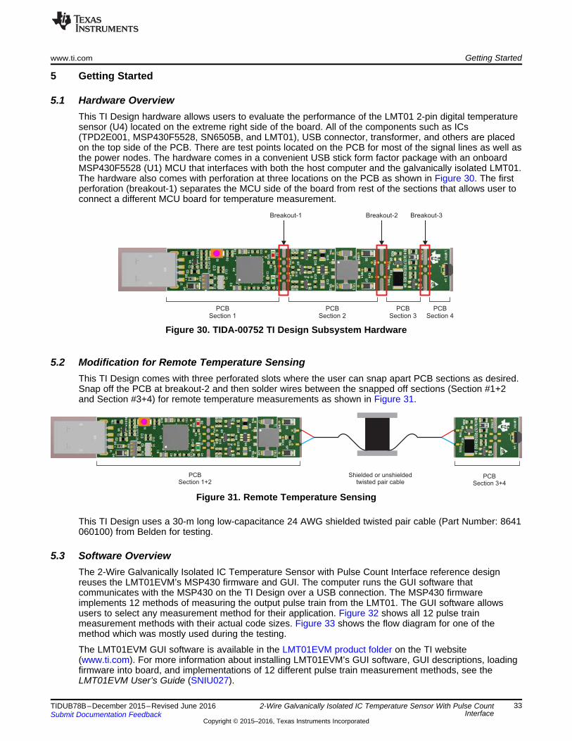
5.1 Hardware OverviewThis TI Design hardware allows users to evaluate the performance of the LMT01 2-pin digital temperaturesensor (U4) located on the extreme right side of the board. All of the components such as ICs(TPD2E001, MSP430F5528, SN6505B, and LMT01), USB connector, transformer, and others are placedon the top side of the PCB. There are test points located on the PCB for most of the signal lines as well asthe power nodes. The hardware comes in a convenient USB stick form factor package with an onboardMSP430F5528 (U1) MCU that interfaces with both the host computer and the galvanically isolated LMT01.The hardware also comes with perforation at three locations on the PCB as shown in Figure 30. The firstperforation (breakout-1) separates the MCU side of the board from rest of the sections that allows user toconnect a different MCU board for temperature measurement.
Figure 30. TIDA-00752 TI Design Subsystem Hardware
5.2 Modification for Remote Temperature SensingThis TI Design comes with three perforated slots where the user can snap apart PCB sections as desired.Snap off the PCB at breakout-2 and then solder wires between the snapped off sections (Section #1+2and Section #3+4) for remote temperature measurements as shown in Figure 31.
Figure 31. Remote Temperature Sensing
This TI Design uses a 30-m long low-capacitance 24 AWG shielded twisted pair cable (Part Number: 8641060100) from Belden for testing.
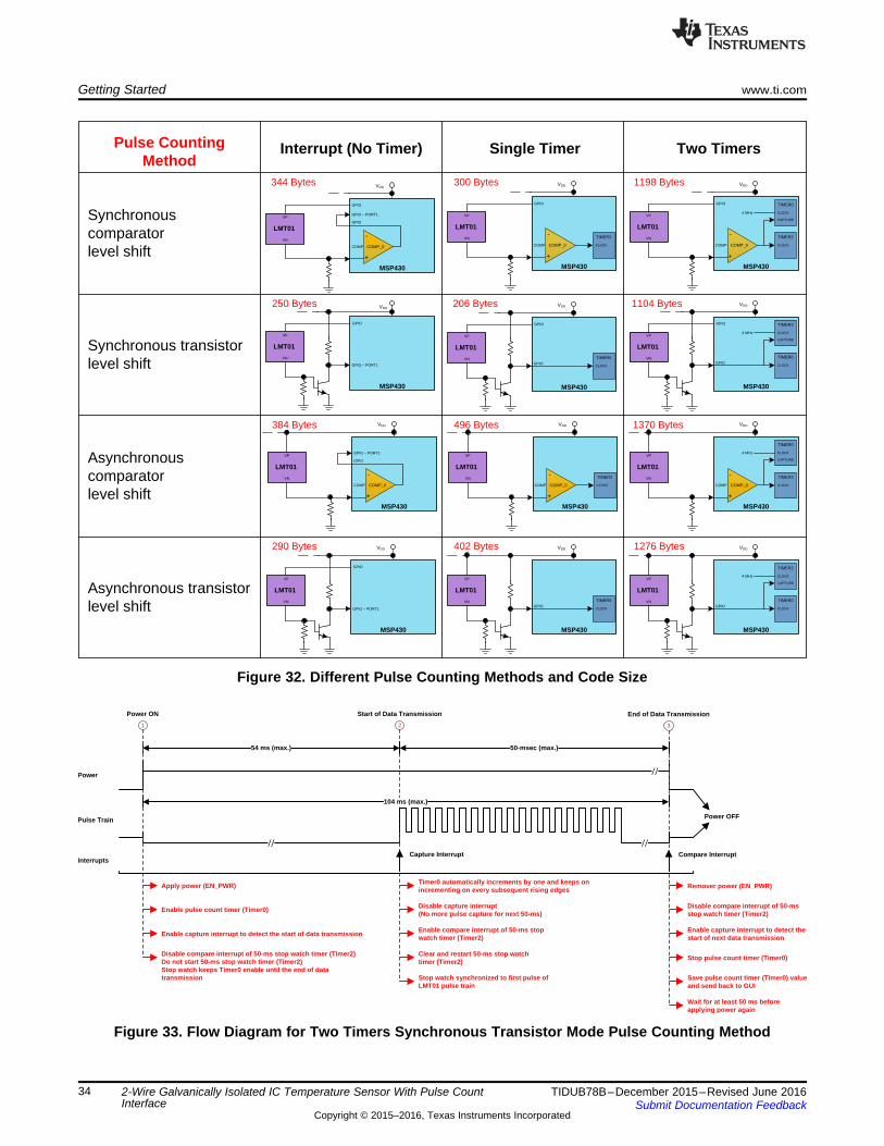
5.3 Software OverviewThe 2-Wire Galvanically Isolated IC Temperature Sensor with Pulse Count Interface reference designreuses the LMT01EVM’s MSP430 firmware and GUI. The computer runs the GUI software thatcommunicates with the MSP430 on the TI Design over a USB connection. The MSP430 firmwareimplements 12 methods of measuring the output pulse train from the LMT01. The GUI software allowsusers to select any measurement method for their application. Figure 32 shows all 12 pulse trainmeasurement methods with their actual code sizes. Figure 33 shows the flow diagram for one of themethod which was mostly used during the testing.
The LMT01EVM GUI software is available in the LMT01EVM product folder on the TI website(www.ti.com). For more information about installing LMT01EVM’s GUI software, GUI descriptions, loadingfirmware into board, and implementations of 12 different pulse train measurement methods, see theLMT01EVM User’s Guide (SNIU027).
Enable capture interrupt to detect the start of data transmission
Disable compare interrupt of 50-ms stop watch timer (Timer2)Do not start 50-ms stop watch timer (Timer2)Stop watch keeps Timer0 enable until the end of data transmission
2
Disable capture interrupt (No more pulse capture for next 50-ms)
Enable compare interrupt of 50-ms stop watch timer (Timer2)
Clear and restart 50-ms stop watch timer (Timer2)
Stop watch synchronized to first pulse of LMT01 pulse train
Timer0 automatically increments by one and keeps on incrementing on every subsequent rising edges
Power
Pulse Train
Power ON Start of Data Transmission
3
Enable capture interrupt to detect the start of next data transmission
Stop pulse count timer (Timer0)
Save pulse count timer (Timer0) value and send back to GUI
Disable compare interrupt of 50-ms stop watch timer (Timer2)
End of Data Transmission
//
50-msec (max.)
104 ms (max.)
InterruptsCapture Interrupt Compare Interrupt
Remover power (EN_PWR)
Wait for at least 50 ms before applying power again
Power OFF
Two Timers
-
+
COMP_0COMP
MSP430
TIMER2
CLOCK
TIMER0
CLOCK
CAPTURE
4 MHz
GPIO
LMT01
VP
VN
VDD
Single TimerInterrupt (No Timer)Pulse Counting Method
1198 Bytes300 Bytes344 Bytes
-
+
COMP_0COMP
MSP430
TIMER2
CLOCK
GPIO
LMT01
VP
VN
VDD
-
+
COMP_0COMP
MSP430
GPIO
LMT01
VP
VN
VDD
-
+
COMP_0COMP
MSP430
TIMER2
CLOCK
TIMER0
CLOCK
CAPTURE
4 MHz
LMT01
VP
VN
VDD
-
+
COMP_0COMP
MSP430
TIMER2
CLOCK
LMT01
VP
VN
VDD
-
+
COMP_0COMP
MSP430
LMT01
VP
VN
VDD
1104 Bytes206 Bytes250 Bytes
384 Bytes 496 Bytes 1370 Bytes
1276 Bytes402 Bytes290 Bytes
VDD
GPIO
MSP430
TIMER0
CLOCK
GPIO
LMT01
VP
VN
GPIO ± PORT1
MSP430
GPIO
LMT01
VP
VN
VDD
GPIO
GPIO ± PORT1
GPIO
GPIO ± PORT1
GPIO
MSP430
TIMER0
CLOCK
TIMER2
CLOCK
CAPTURE
4 MHz
GPIO
LMT01
VP
VN
VDD
GPIO
MSP430
TIMER0
CLOCK
TIMER2
CLOCK
CAPTURE
4 MHz
LMT01
VP
VN
VDD
GPIO
MSP430
TIMER0
CLOCK
LMT01
VP
VN
VDD
GPIO ± PORT1
MSP430
GPIO
LMT01
VP
VN
VDD
Synchronous comparator level shift
Synchronous transistorlevel shift
Asynchronous comparatorlevel shift
Asynchronous transistorlevel shift
Getting Started www.ti.com
34 TIDUB78B–December 2015–Revised June 2016Submit Documentation Feedback
2-Wire Galvanically Isolated IC Temperature Sensor With Pulse CountInterface
6 Test Data
NOTE: Unless otherwise noted, the test data in the following sections were measured with thesystem at room temperature.
NOTE: All of the measurements in this section were measured with calibrated lab equipment.
6.1 OverviewSome of the functional and environmental testing was also performed to verify how the reference designacts in different environments. The following subsections describe the test setup, procedures, and testdata with some explanation.
6.2 Power Supply Ramp RateSince the LMT01 is only a 2-pin device, the power pins are common with the signal pins. As a result, theLMT01 has a floating supply that can vary greatly. The LMT01 has an internal regulator that provides astable voltage to internal circuitry. Power supply ramp rate can affect the accuracy of the first resulttransmitted by the LMT01. Therefore, it is recommended that either the power supply be within the finalvalue before a conversion is used or that ramp rates be faster than 2.5 ms. The measures rise time of theLMT01 power supply (VP) is 1.158 ms as shown in Figure 34.
2-Wire Galvanically Isolated IC Temperature Sensor With Pulse CountInterface
6.3 Test for No Missing PulsesOther than the LMT01, the only place that can introduce error in the measurement is pulse counting in theMCU. If the MCU is unable to detect even a single pulse, it adds an error of 0.0625ºC in themeasurement. Therefore, it is really important to make sure that the interface is robust and the MCU doesnot miss any pulse generated by the LMT01.
However, it is difficult to test for any missing pulses with the LMT01 connected in the circuit because it isunknown exactly how many pulses the LMT01 is going to transmit. The simplest way to test this is toremove the LMT01 from circuit and connect an arbitrary function generator as shown in Figure 35. Thisreference design uses AFG3051C Arbitrary Function Generator from Tektronix to simulate the LMT01pulse output functionality. Now change these functional generator settings to generate a repetitive burst ofsquare waveform with a known number of pulses:• Frequency: 88 kHz• Amplitude: VOH = 1.25 V and VOL = 0.34 V (Similar to the voltage levels produced by the LMT01 across
a 10-kΩ resistor)• Function: Square waveform• Period: 104 ms• Pulses (PC): Varied from 32 to 3200
Figure 35. Test Setup for No Missing Pulses
Now the pulse count was increased from 32 to 3200 in increments of 32 pulses, representing atemperature between –50ºC to 150ºC. The LMT01EVM’s GUI was used to log the pulses counted by theMCU for about 5 minutes at each set pulse count. At the end of the test, the log files were verified and itwas found that MCU does not miss any pulse.
2-Wire Galvanically Isolated IC Temperature Sensor With Pulse CountInterface
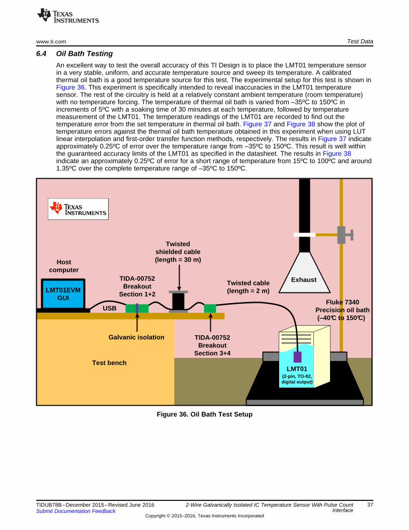
6.4 Oil Bath TestingAn excellent way to test the overall accuracy of this TI Design is to place the LMT01 temperature sensorin a very stable, uniform, and accurate temperature source and sweep its temperature. A calibratedthermal oil bath is a good temperature source for this test. The experimental setup for this test is shown inFigure 36. This experiment is specifically intended to reveal inaccuracies in the LMT01 temperaturesensor. The rest of the circuitry is held at a relatively constant ambient temperature (room temperature)with no temperature forcing. The temperature of thermal oil bath is varied from –35ºC to 150ºC inincrements of 5ºC with a soaking time of 30 minutes at each temperature, followed by temperaturemeasurement of the LMT01. The temperature readings of the LMT01 are recorded to find out thetemperature error from the set temperature in thermal oil bath. Figure 37 and Figure 38 show the plot oftemperature errors against the thermal oil bath temperature obtained in this experiment when using LUTlinear interpolation and first-order transfer function methods, respectively. The results in Figure 37 indicateapproximately 0.25ºC of error over the temperature range from –35ºC to 150ºC. This result is well withinthe guaranteed accuracy limits of the LMT01 as specified in the datasheet. The results in Figure 38indicate an approximately 0.25ºC of error for a short range of temperature from 15ºC to 100ºC and around1.35ºC over the complete temperature range of –35ºC to 150ºC.
2-Wire Galvanically Isolated IC Temperature Sensor With Pulse CountInterface
Figure 37. LMT01 Accuracy When Using LUT Linear Interpolation
Figure 38. LMT01 Accuracy When Using First-Order Transfer Function
When compared, the improved performance when using the LUT linear interpolation method can clearlybe seen. For a limited temperature range of 25°C to 90°C, the error shown in Figure 38 is pretty flat andthus the linear equation provides good results. For a wide temperature range, use linear interpolation andthe LUT.
2-Wire Galvanically Isolated IC Temperature Sensor With Pulse CountInterface
6.5 IEC61000-4-4 EFTThis TI Design was characterized through pre-compliance test for EFT using a 30-m long shielded twistedpair cable.
Table 3. Criteria and Performance as Per IEC61131-2
CRITERIA PERFORMANCE (PASS) CRITERIAA The system shall continue to operate as intended with no loss of function or performance even during the test.
B Temporary degradation of performance is accepted. After the test, the system shall continue to operate asintended without manual intervention.
C During the test, loss of functions accepted, but no destruction of hardware or software. After the test, the systemmust continue to operate as intended automatically, after a manual restart, powering off, or powering on.
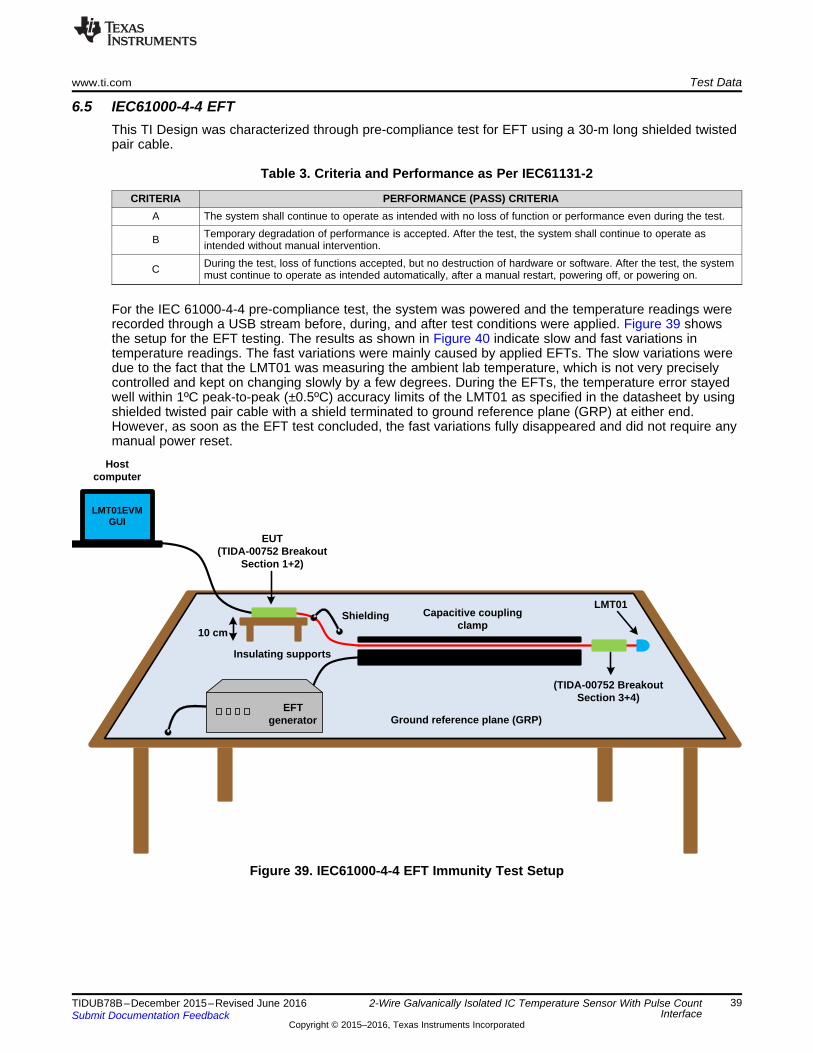
For the IEC 61000-4-4 pre-compliance test, the system was powered and the temperature readings wererecorded through a USB stream before, during, and after test conditions were applied. Figure 39 showsthe setup for the EFT testing. The results as shown in Figure 40 indicate slow and fast variations intemperature readings. The fast variations were mainly caused by applied EFTs. The slow variations weredue to the fact that the LMT01 was measuring the ambient lab temperature, which is not very preciselycontrolled and kept on changing slowly by a few degrees. During the EFTs, the temperature error stayedwell within 1ºC peak-to-peak (±0.5ºC) accuracy limits of the LMT01 as specified in the datasheet by usingshielded twisted pair cable with a shield terminated to ground reference plane (GRP) at either end.However, as soon as the EFT test concluded, the fast variations fully disappeared and did not require anymanual power reset.
2-Wire Galvanically Isolated IC Temperature Sensor With Pulse CountInterface
Figure 40. Performance During EFT Immunity Test Using Shielded Twisted Pair Cable
When using shielded cables, it is also necessary to determine how the shielding will be bonded otherwisethe benefits are considerably reduced. To be effective, the shielding should be bonded over 360°.Figure 41 shows different ways of earthing the cable shielding. Use cable rounding clamp as shown inFigure 42 to improve bonding between the cable shield and GRP and off-course for better results.
9 About the AuthorsSHARAD YADAV is a Systems Engineer at Texas Instruments India where he is responsible fordeveloping reference design solutions for the industrial segment. Sharad has eight years of experience inhigh-speed digital, mixed-signal boards, low-noise analog, and EMC protection circuit design.
MIROSLAV OLJACA is the End Equipment Lead for building automation applications and systemsolutions. Miro has nearly 30 years of engineering experience and has been granted at least a dozenpatents, several related to high performance signal processing, and he has written many articles on thesubject. Miro received his BSEE and MSEE from the University of Belgrade, Serbia.
Revision B HistoryNOTE: Page numbers for previous revisions may differ from page numbers in the current version.
Changes from A Revision (March 2016) to B Revision .................................................................................................. Page
• Deleted Room Monitors, Appliances, and Power Supplies and Battery Thermal Management from FeaturedApplications ................................................................................................................................ 1
Revision A History
Changes from Original (December 2015) to A Revision ................................................................................................ Page
• Changed from preview page............................................................................................................. 1
Texas Instruments Incorporated (‘TI”) reference designs are solely intended to assist designers (“Designer(s)”) who are developing systemsthat incorporate TI products. TI has not conducted any testing other than that specifically described in the published documentation for aparticular reference design.TI’s provision of reference designs and any other technical, applications or design advice, quality characterization, reliability data or otherinformation or services does not expand or otherwise alter TI’s applicable published warranties or warranty disclaimers for TI products, andno additional obligations or liabilities arise from TI providing such reference designs or other items.TI reserves the right to make corrections, enhancements, improvements and other changes to its reference designs and other items.Designer understands and agrees that Designer remains responsible for using its independent analysis, evaluation and judgment indesigning Designer’s systems and products, and has full and exclusive responsibility to assure the safety of its products and compliance ofits products (and of all TI products used in or for such Designer’s products) with all applicable regulations, laws and other applicablerequirements. Designer represents that, with respect to its applications, it has all the necessary expertise to create and implementsafeguards that (1) anticipate dangerous consequences of failures, (2) monitor failures and their consequences, and (3) lessen thelikelihood of failures that might cause harm and take appropriate actions. Designer agrees that prior to using or distributing any systemsthat include TI products, Designer will thoroughly test such systems and the functionality of such TI products as used in such systems.Designer may not use any TI products in life-critical medical equipment unless authorized officers of the parties have executed a specialcontract specifically governing such use. Life-critical medical equipment is medical equipment where failure of such equipment would causeserious bodily injury or death (e.g., life support, pacemakers, defibrillators, heart pumps, neurostimulators, and implantables). Suchequipment includes, without limitation, all medical devices identified by the U.S. Food and Drug Administration as Class III devices andequivalent classifications outside the U.S.Designers are authorized to use, copy and modify any individual TI reference design only in connection with the development of endproducts that include the TI product(s) identified in that reference design. HOWEVER, NO OTHER LICENSE, EXPRESS OR IMPLIED, BYESTOPPEL OR OTHERWISE TO ANY OTHER TI INTELLECTUAL PROPERTY RIGHT, AND NO LICENSE TO ANY TECHNOLOGY ORINTELLECTUAL PROPERTY RIGHT OF TI OR ANY THIRD PARTY IS GRANTED HEREIN, including but not limited to any patent right,copyright, mask work right, or other intellectual property right relating to any combination, machine, or process in which TI products orservices are used. Information published by TI regarding third-party products or services does not constitute a license to use such productsor services, or a warranty or endorsement thereof. Use of the reference design or other items described above may require a license from athird party under the patents or other intellectual property of the third party, or a license from TI under the patents or other intellectualproperty of TI.TI REFERENCE DESIGNS AND OTHER ITEMS DESCRIBED ABOVE ARE PROVIDED “AS IS” AND WITH ALL FAULTS. TI DISCLAIMSALL OTHER WARRANTIES OR REPRESENTATIONS, EXPRESS OR IMPLIED, REGARDING THE REFERENCE DESIGNS OR USE OFTHE REFERENCE DESIGNS, INCLUDING BUT NOT LIMITED TO ACCURACY OR COMPLETENESS, TITLE, ANY EPIDEMIC FAILUREWARRANTY AND ANY IMPLIED WARRANTIES OF MERCHANTABILITY, FITNESS FOR A PARTICULAR PURPOSE, AND NON-INFRINGEMENT OF ANY THIRD PARTY INTELLECTUAL PROPERTY RIGHTS.TI SHALL NOT BE LIABLE FOR AND SHALL NOT DEFEND OR INDEMNIFY DESIGNERS AGAINST ANY CLAIM, INCLUDING BUT NOTLIMITED TO ANY INFRINGEMENT CLAIM THAT RELATES TO OR IS BASED ON ANY COMBINATION OF PRODUCTS ASDESCRIBED IN A TI REFERENCE DESIGN OR OTHERWISE. IN NO EVENT SHALL TI BE LIABLE FOR ANY ACTUAL, DIRECT,SPECIAL, COLLATERAL, INDIRECT, PUNITIVE, INCIDENTAL, CONSEQUENTIAL OR EXEMPLARY DAMAGES IN CONNECTION WITHOR ARISING OUT OF THE REFERENCE DESIGNS OR USE OF THE REFERENCE DESIGNS, AND REGARDLESS OF WHETHER TIHAS BEEN ADVISED OF THE POSSIBILITY OF SUCH DAMAGES.TI’s standard terms of sale for semiconductor products (http://www.ti.com/sc/docs/stdterms.htm) apply to the sale of packaged integratedcircuit products. Additional terms may apply to the use or sale of other types of TI products and services.Designer will fully indemnify TI and its representatives against any damages, costs, losses, and/or liabilities arising out of Designer’s non-compliance with the terms and provisions of this Notice.IMPORTANT NOTICE