52
The Airbus safety magazine July 2014 Safety first #18 The Airbus Safety Magazine July 2015 Safety first #20
The Airbus safety magazineJuly 2014
Safety first
#18
The Airbus Safety MagazineJuly 2015
Safety first
#20

Safety First #20 | July 2015002
Safety first is published by the Product Safety depart-ment. It is a source of specialist safety information for the restricted use of flight and ground crew members who fly and maintain Airbus aircraft. It is also distributed to other selected organisations.
Material for publication is obtained from multiple sources and includes selected information from the Airbus Flight Safety Confidential Reporting System, incident and acci-dent investigation reports, system tests and flight tests. Material is also obtained from sources within the airline industry, studies and reports from government agencies and other aviation sources.
All articles in Safety first are presented for information only and are not intended to replace ICAO guidelines, stand-ards or recommended practices, operator-mandated requirements or technical orders. The contents do not supersede any requirements mand ated by the State of Registry of the Operator’s aircraft or supersede or amend any Airbus type-specific AFM, AMM, FCOM, MMEL docu-mentation or any other approved documentation.
Articles may be reprinted without permission, except where copyright source is indicated, but with acknowl-edgement to Airbus. Where Airbus is not the author, the contents of the article do not necessarily reflect the views of Airbus, neither do they indicate Company policy.
Contributions, comment and feedback are welcome. For technical reasons the editors may be required to make editorial changes to manuscripts, however every effort will be made to preserve the intended meaning of the original. Enquiries related to this publication should be addressed to:
AirbusProduct Safety department (GS)1, rond point Maurice Bellonte31707 Blagnac Cedex - [email protected]: +33(0)5 61 93 44 29
Safety firstThe Airbus magazine contributing to the enhancement of the safety of aircraft operations by increasing knowledge and communication on safety related topics.
Safety first, #20 July, 2015. Safety first is published by Airbus S.A.S. - 1, rond point Maurice Bellonte - 31707 Blagnac Cedex/France. Publisher: Yannick Malinge, Chief Product Safety Officer, Editor: Corinne Bieder, Director Product Safety Strategy & Communication. Concept Design by Airbus Multi Media Support 20151274. Reference: GS 420.0045 Issue 20. Photos by Airbus, H. Goussé, Lindner Fotografie, A. Doumenjou, P. Pigeyre, P. Masclet, B. Sveinsson, C. Brinkmann, Aneese. Printed in France.
This brochure is printed on Triple Star Satin. This paper is produced in factories that are accredited EMAS and certified ISO 9001-14001, PEFC and FSC CoC. It is produced using pulp that has been whitened without either chlorine or acid. The paper is entirely recyclable and is produced from trees grown in sustainable forest resources. The printing inks use organic pigments or minerals. There is no use of basic dyes or dangerous metals from the cadmium, lead, mercury or hexavalent chromium group.
© Airbus S.A.S. 2015 – All rights reserved. Proprietary documents.
By taking delivery of this Brochure (hereafter “Brochure”), you accept on behalf of your company to comply with the following guidelines:
No other intellectual property rights are granted by the delivery of this Brochure than the right to read it, for the sole purpose of information.
This Brochure and its content shall not be modified and its illustrations and photos shall not be reproduced without prior written consent of Airbus.
This Brochure and the materials it contains shall not, in whole or in part, be sold, rented, or licensed to any third party subject to payment.
This Brochure contains sensitive information that is correct at the time of going to press.
This information involves a number of factors that could change over time, effecting the true public representation. Airbus assumes no obligation to update any information contained in this document or with respect to the information described herein.
Airbus S.A.S. shall assume no liability for any damage in connection with the use of this Brochure and of the materials it contains, even if Airbus S.A.S. has been advised of the likelihood of such damages.

editorialYANNICK MALINGESVP & Chief Product Safety Officer
In the current era of wealth of data where Big Data, smart data and other data related trends emerge, a key question arises: what can data tell us, and under what conditions?
Over the past decades, safety has evolved from primarily reactive approaches such as accident and incident inves-tigation, to more proactive approaches to try to anticipate and thus prevent safety issues. In line with this evolution, there is a change of scale in the nature and the amount of data. If Big Data seems a promising complement to two other pillars of efficient safety enhancement - namely proper reporting and cascading of lessons learned - it requires some careful consideration as to how the data are collected and analysed.
From statistical patterns identified to relevant safety rec-ommendations, the way is long and involves interpreta-tion, sense-making… often requiring a qualitative analysis calling for a good knowledge and understanding of oper-ations and safety context.
With this in mind, we must take great care with some Big Data approaches that use a variety of sources of data collected for a variety of purposes and through a generic and somehow magic algorithm come out with apparently very credible “safety results”. Can we confuse “big” with “good” when it comes to data? Is it reasonable to make the assumption that big amounts of data could be self-sense-making?
Evolving towards more proactive approaches, better understanding of normal operations and detecting trends are keys to further enhancements in safety. However, whatever the amount of data, the experience of aviation professionals is essential to make sure they are processed and interpreted wisely.
Safety First #20 | July 2015002
We are pleased to announce that the 22 Flight Safety Conference will take place in Bangkok, Thailand, from the 21 to the 24 of March 2016. The for-mal invitations with information regard-ing registration and logistics, as well as the preliminary agenda will be sent to our customers in January 2016.For any information regarding invita-tions, please contact Mrs. Nuria Soler, email [email protected].
The Flight Safety Conference provides an excellent forum for the exchange of information between Airbus and its customers. To ensure that we can
have an open dialogue to promote flight safety across the fleet, we are unable to accept outside parties.
As always, we welcome presentations from our operators. You can partic-ipate as a speaker and share your ideas and experience for improving aviation safety.If you have something you believe will benefit other operators and/or Air-bus and if you are interested in being a speaker, please provide us with a brief abstract and a bio or resume at [email protected].
NEWS
22nd FLIGHT SAFETY CONFERENCE – 2016
SAVE THE DATE
NEWS
The new edition of our yearly brochure on commercial aviation accidents sta-tistics is now available. This statistical analysis examines the evolution of hull-loss and fatal accidents during revenue flights from 1958 to 2014. A particular focus is made on a breakdown of statistics by generations of aircraft and main accident categories, namely Controlled Flight Into terrain (CFIT), Loss Of Con-trol In-flight (LOC-I) and Runway Excursion (RE).
Visit our airbus.com website (keyword “safety”) or find it on our tablet application.
A statistical Analysis on Commercial Aviation Accidents: check the 2015 edition!

22nd Flight Safety ConferenceBangkok, 21-24 March 2016

Safety First #20 | July 2015004

005Safety First #18 | July 2014
Flight operations
Maintenance
Engineering
Ground operations
#20Safety first
P14Lateral runway excursions upon landing
PROCEDURES
P06Control your speed... during climb
OPERATIONS
P28Fuel monitoring on A320 Family aircraft
GENERAL TOPIC
P36High-altitude manual flying

Safety First #20 | July 2015006
Control your speed… during climbSecond of a series of articles on the theme of speed control during a flight, which started in issue #18 of this magazine, we have just taken off and are now entering the climb phase. The main objective is to retract the slats / flaps at an adequate speed, while sustaining enough lift to accelerate and climb.
PHILIPPE CASTAIGNSExperimental Test Pilot
LORRAINE DE BAUDUSFlight Operations Standards and Safety management
Control your speed... during climbPROCEDURES

007Safety First #20 | July 2015
After take-off, the aircraft continues in the climb phase and flies away from the busy airspace. The objective for the crew is to accelerate to the en-route climb speed and at the same time, manage various aircraft configuration changes, usually consisting of gears, slats and flaps retraction, and a change from take-off power to climb power.
This article aims at shedding some light on the way the different maneuvering and limit speeds that are of use during climb are defined and determined, and how they can be implemented in daily operations.
A climb is generally flown at an airspeed that is often initially limited by Air Traffic Control (ATC) instructions. To safely manage the climb phase within these restrictions, some characteristic speeds are useful tools, and they require a close monitoring. What speeds exactly should be monitored? What do these speeds mean and what happens if they are exceeded?
For every flight, characteristic speeds are computed automatically by the aircraft Auto Flight Systems (Flight Management System (FMS), Flight Guidance (FG) and Flight Enve-lope (FE)) and effectively displayed on the PFD airspeed scale. They are extremely useful as maneu-vering speeds and limit speeds to safely guide the pilots configuration change decisions through the climb phase.
Our objective is to highlight the design and operational considerations under- lying all recommendations Airbus has issued to flight crews regarding the monitoring of these speeds during climb.Amongst other parameters, the maneu-vering speeds Flaps (F), Slats (S) and Green Dot (GD) are a function of the Zero Fuel Weight (ZFW) inserted by the crew at FMS initialization. Therefore, any erroneous entry will impair these speeds.
MANAGING YOUR CLIMB: UNDERSTANDING SPEEDS
Maneuvering speeds
In nominal conditions (all engines oper-ative), the climb phase poses some challenges to the crew: accelerate the aircraft, maintain a satisfactory climb gradient and manage several config-uration changes at the same time. To
help pilots fly their aircraft safely through the different steps of this phase of flight, some characteristic speeds were defined as maneuvering speeds.F, S and Green Dot speeds frame the aircraft climb performance limits.
F, S and Green Dot speeds frame the aircraft climb performance limits.

F and S: Flaps and Slats minimum retraction speeds
Definitions
F speed is the minimum speed at which flaps should be retracted from CONF 3 or 2 to CONF 1+F.
It is represented by a green “F” on the PFD speed scale and displayed only when the slats / flaps control lever is on position 3 or 2 (CONF 3 or 2) dur-ing the take-off phase, the initial climb and go-around (fig.1). It is no longer displayed when in configuration 1 or 1+F.
S speed is the minimum slats retrac-tion speed, i.e. the minimum speed at which a clean configuration should be selected.
It is represented by a green “S” on the PFD speed scale and displayed only when the slats / flaps control lever is on position 1 (CONF 1 and 1+F) (fig.2).
How are F and S determined during the take-off phase?
F speed varies according to the air-craft weight and altitude. It is tab-ulated in the Flight Envelope as a function of VS1g CONF 1+ F , which is the reference stall speed demonstrated by flight tests and agreed by the Air-worthiness Authorities.
In this respect, F speed allows a mar-gin above the stall speed in the con-figuration 1+F.
(fig.1) F on the PFD speed scale
F speed
(fig.2) S on the PFD speed scale
S speed
F speed = k x VS1g CONF 1+F , with k equal to about 1.18 to 1.26VMCL + 5 kts ≤ F ≤ VFE CONF FULL – 2 kts
S speed varies according to the air-craft weight and altitude. It is tabu-lated in the Flight Envelope as a func-tion of VS1g CLEAN CONF.
In this respect, S speed allows a mar-gin above the stall speed in the clean configuration.
Green Dot (GD): best lift-to-drag ratio
Definition
GD speed is the engine-out operat-ing speed in clean configuration. In other words, it corresponds to the speed that allows the highest climb gradient with one engine inoperative in clean configuration.In all cases (all engines operative), the GD speed gives an estimate of the speed for best lift-to-drag ratio. It is also the final take-off speed and it
represents the operational speed of the clean configuration and the rec-ommended speed in holding in clean configuration.
It is represented by a green dot on the PFD speed scale and displayed only when the slats / flaps control lever is in the ‘0’ (CLEAN) position and landing gears are not compressed (fig.3).
S = k x VS1g CLEAN CONF , with k equal to about 1.21 to 1.25
(fig.3) GD on the PFD speed scale
GD speed
Control your speed... during climbPROCEDURES

009Safety First #20 | July 2015
How is GD determined?
GD speed is computed by the Auto- flight systems and is based on the aircraft weight. The GD formula has been set up so that the resulting air-speed provides the best lift-to-drag ratio for a given altitude, air tempera-
ture and aircraft weight, in clean con-figuration with one engine out.In some phases of flight, GD is com-puted to minimize drag and thus, the fuel consumption (for example during the HOLD phase).
Limit speed
We have seen that deviations from the maneuvering speeds F, S and GD during climb can have an impact on the aircraft’s aerodynamic performance. We will now focus on the limit speed VFE.
VFE: Maximum speed with Flaps Extended
With the A/THR engaged and active (CLB / OP CLB / SPEED green on FMA), the aircraft remains below VFE.
When the A/THR is not active, VFE exceedance may occur (for example during a go-around).
Definition
VFE is the maximum speed with flaps extended. It has a specific value for each flap setting.Generally speaking, the maximum speed defining the aircraft’s flight envelope is called VMAX. VMAX is equal to VLE (maximum speed with landing
gears extended) or VFE according to the aircraft configuration. VMAX is equal to VMO (or speed corresponding to MMO) only in the clean configuration.On the PFD speed scale, it corre-sponds to the lower end of the red and black strip (fig.4).
How is VFE determined?
VFE is the maximum speed for high lift configurations, i.e. with slats / flaps extended: it is related to the structural limitation of the slats / flaps. A VFE is computed for each slats / flaps con-figuration, based on either the slats / flaps control lever position or the actual aircraft configuration (slats / flaps con-
trol surfaces position), depending on the aircraft type.
In order to keep a sufficient margin between the VFE CONF 3 and the speed at which the next configuration is selected, the following inequality is met: VFE CONF 3 ≥ F + 10 kts.
(fig.4) V on the PFD speed scale
V display

GD IN A NUTSHELL
Avoid flying below GD during climb.
MANAGING YOUR CLIMB: OPERATIONAL RECOMMENDATIONS
Flying a safe and steady climb requires pilots’ attention to carefully manage the different configuration changes, while accelerating to the en-route climb speed and eventually, cruise speed.
Indeed, not respecting the maneuver-ing and limit speeds leads to adverse consequences that we will review. Avoiding an overspeed situation dur-ing the slats / flaps retraction - with its potential structural damage conse-
quences - is important. It is therefore worth understanding the different VFE display logics implemented in each aircraft family, and the resulting over-speed aural warning behaviour during the climb.
What are the operational implications of not respecting the maneuvering or limit speeds?
F and S: Flaps and Slats minimum retraction speeds
F speed (resp. S) is defined as the rec-ommended minimum flaps (resp. slats) retraction speed. Retracting the flaps (resp. slats) at a speed significantly lower than F (resp. S) would reduce the margin against the high Angle-Of-Attack (AOA) protection. This could lead the aircraft to reach a speed below the lowest selecta-ble speed VLS CONF 1 (or 0), and pos-sibly low enough to break through the high AOA protection threshold.
Retracting the flaps (resp. slats) at a speed significantly higher than F speed (resp. S) would reduce the climb performance and thus, possi-bly compromise the aircraft ability to clear any obstacles (this is more likely if one engine is inoperative).If flaps need to be maintained for a turn before acceleration altitude for instance, F speed (resp. S) can be used safely to perform a turn while climbing.
GD: Green Dot
At a given weight and engine rating, the potential climb gradient is maxi- mum when (Thrust – Drag) is at a maximum - i.e. when the lift-to-drag ratio is maximum.
Deviating below GD involves an increase in the drag on the aircraft and would eventually undermine the aircraft’s ability to continue a climb. Indeed, if the aircraft speed goes sig-nificantly below GD, with the maxi- mum available thrust already in use (assuming that thrust levers have just
been set to CLIMB / MCT), then the only way for the crew to recover a sat-isfactory climb gradient is to decrease the rate of climb (even enter a descent if necessary) in order to accelerate to or above GD. This maneuver is obvi-ously counteractive to the objectives of the climb phase.
Therefore in the clean configuration, the crew should not fly below GD in order to avoid degrading climb per-formance.
Control your speed... during climbPROCEDURES

011Safety First #20 | July 2015
MANAGING YOUR CLIMB: OPERATIONAL RECOMMENDATIONS
VFE IN A NUTSHELL
Do not fly with slats / flaps extended above VFE.
How to avoid an overspeed during slats / flaps retraction?Avoiding an overspeed during slats / flaps retraction relies on a variety of complementary aspects. Proce-dures, pilots’ attention and coordi-nation, anticipation of configuration
changes, understanding of the limit speed and of the different VFE display logics and overspeed aural warning behaviour implemented in each air-craft family.
The common approach
Slats and flaps retraction during climb can be managed safely by fol-lowing SOP, and observing the visual F and S indications on the PFD. Inci-dentally, doing so allows the crew to respect the VFE indication displayed on the PFD and thus, avoid trigger-ing an aural overspeed warning (with potential structural damage).The use of A/THR also enables the crew to avoid an overspeed condi-tion during slats / flaps retraction.
While the PF is expected to manage these configuration changes, the PM plays a key role in facilitating his/her
task by anticipating them. During the initial climb phase, the PM needs to be vigilant to speed trends and alert the PF in case the margin that is left against the applicable limit speed VFE becomes too tight.This is valid at all time, for all aircraft families.
Differences arise when we look more closely at the VFE display logics for each family. In particular, we want to emphasize the possibility of a tem-porary, yet inconsequential, over-speed aural warning on A300/A310, A320 and A330/A340 Families.
VFE: Maximum speed with flaps extended
In case of take-off with A/THR not active, flying with slats / flaps extended, or extending slats / flaps well above VFE directly poses a risk of structural damage through the slats / flaps track mechanisms. This may result in distortion of the flaps and slats or the extension mechanism or even the aircraft structure upstream. In case VFE is exceeded, an over-speed aural warning is triggered in the cockpit in order to alert the crew.
The flight crew will have to reduce the speed or to retract the slats / flaps accordingly.Exceeding VFE may subsequently trigger inspections of the slats/ flaps mechanism and/or the aircraft structure.Specific trouble shooting procedures exist to inspect and repair an aircraft after flight above VFE. These proce-dures are available in the Aircraft Maintenance Manual (AMM).

The case of untimely temporary overspeed aural warning during slats / flaps retraction
A300/A310, A320 and A330/A340 Families
On A300/A310, A320 and A330/A340 Families,• The VFE value displayed on the PFD
is based on the slats / flaps con-trol lever position and it moves by one step as soon as this lever is moved.
• The overspeed aural warning trig-gering threshold varies according to the actual aircraft configuration, i.e. the slats / flaps surfaces real time position.
Therefore, during slats / flaps tran-sition, the dynamic acceleration of the airplane may lead to a temporary OVERSPEED WARNING even if the current speed is out of the red and black strip displayed on the PFD. In this situation, there are neither opera-tional consequences nor safety issues.
This is due to the following logic:• When the flap lever is moved from
CONF 2 (or 3) to CONF 1+F, F speed could be very close to VFE before flaps retraction. Once the flap retraction is initiated, VFE CONF (2 or 3) moves in one step to VFE CONF 1+F before the flaps actually reach CONF 1+F. As a con-sequence, in acceleration towards S speed, the VFE aural warning could activate although the actual surfaces speed is below the displayed VFE.
• When the flap lever is moved from CONF 2 (or 3) to CONF 1+F, S speed could be greater than VFE CONF 1+F before the surfaces retract. When automatic flap retraction occurs, the barbers pole does not move before the flaps fully retract.
A350 and A380 Families
On A350 and A380 Families, a differ-ent logic was developed. The VFE dis-play on the PFD is directly based on the actual aircraft configuration, as is the overspeed aural warning trigger-
ing threshold. This means that the two signals are perfectly synchro-nized, thus the risk of an untimely temporary overspeed warning is eliminated.
The case of temporary overspeed aural warning during slats / flaps retraction after a heavy-weight take-off
In the particular case of a heavy-weight take-off, the risk of a tem-porary overspeed aural warn-ing is increased. Indeed, in this configuration, S speed is quite close to VFE CONF 1+F because the aircraft weight is higher and the lift needed to climb is higher too. Therefore the slats need to remain extended for longer. As a result, the crew will order flaps retrac-tion at a speed that might be higher than the Flaps Auto-retraction speed. In that case, should the acceleration of the airplane be rapid, a VFE aural warning may momentarily trigger. This logic is as per design and struc-tural limits are not encountered.
For example, an A320 at a Take-Off Weight (TOW) of 76T, S speed of 205 kts, the pilot will order flaps retraction most probably at or slightly above 210 kts, which is precisely the Flaps Auto-retraction speed. Once the slats / flaps control lever is in the retracted position, the VFE red and black strip is no longer displayed on the PFD speed scale. If the airplane acceler-ates rapidly, then the airspeed may catch up the actual instantaneous VFE momentarily, which will trigger the VFE aural warning. Again, this logic is as per design and structural limits are not en- countered.
Control your speed... during climbPROCEDURES
BEST PRACTICE
After a heavy-weight take-off, do not delay slats / flaps 0 selection above S speed in order to prevent possi-ble temporary VFE overspeed aural warning.

013Safety First #20 | July 2015
During climb, in manual flight, the main risk is to experience an aural overspeed warning (with potential structural damage) as a result of a late slats / flaps retraction. Understanding the implications of climb speeds is paramount to enable pilots to sense instantly the available margin they have left to avoid exceeding the limit slats / flaps retrac-tion speed.
In practice, once the aircraft is airborne, pilots must be fully cognisant of the airspeed as well as the speed trends at all time in flight.
DID YOU KNOWTo know more about speeds, read our brochure “Getting to grips with aircraft performance”, available on AirbusWorld.A presentation was also made at the 11th Perf and Flight Ops Conference in Dubai in 2011.

Safety First #20 | July 2015014
Lateral runway excursions upon landingLateral runway excursions upon landing have long been rather low on the safety issues list. With the remarkable improvements in other areas, they are getting higher up and deserve careful attention. The analysis of real cases allows for drawing interesting lessons on these events and reinforcing prevention.
SAMUEL PELLETProduct Safety enhancement analysis engineer
MATTHIEU MAYOLLEStability & control engineer
Lateral runway excursions upon landingPROCEDURES
XAVIER LESCEUTest Pilot
015Safety First #20 | July 2015
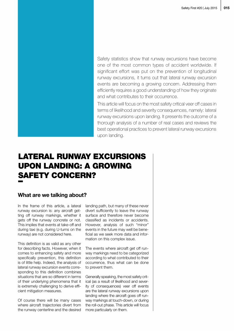
Safety statistics show that runway excursions have become one of the most common types of accident worldwide. If significant effort was put on the prevention of longitudinal runway excursions, it turns out that lateral runway excursion events are becoming a growing concern. Addressing them efficiently requires a good understanding of how they originate and what contributes to their occurrence.
This article will focus on the most safety critical veer off cases in terms of likelihood and severity consequences, namely: lateral runway excursions upon landing. It presents the outcome of a thorough analysis of a number of real cases and reviews the best operational practices to prevent lateral runway excursions upon landing.
What are we talking about?
In the frame of this article, a lateral runway excursion is: any aircraft get-ting off runway markings, whether it gets off the runway concrete or not. This implies that events at take-off and during taxi (e.g. during U-turns on the runway) are not considered here.
This definition is as valid as any other for describing facts. However, when it comes to enhancing safety and more specifically prevention, this definition is of little help. Indeed, the analysis of lateral runway excursion events corre-sponding to this definition combines situations that are so different in terms of their underlying phenomena that it is extremely challenging to derive effi-cient mitigation measures.
Of course there will be many cases where aircraft trajectories divert from the runway centerline and the desired
landing path, but many of these never divert sufficiently to leave the runway surface and therefore never become classified as incidents or accidents. However, analysis of such “minor” events in the future may well be bene-ficial as we seek more data and infor-mation on this complex issue.
The events where aircraft get off run-way markings need to be categorized according to what contributed to their occurrence, thus what can be done to prevent them.
Generally speaking, the most safety crit-ical (as a result of likelihood and sever-ity of consequences) veer off events are the lateral runway excursions upon landing where the aircraft goes off run-way markings at touch-down, or during the roll-out phase. This article will focus more particularly on them.
LATERAL RUNWAY EXCURSIONS UPON LANDING: A GROWING SAFETY CONCERN?
Statistics say a word
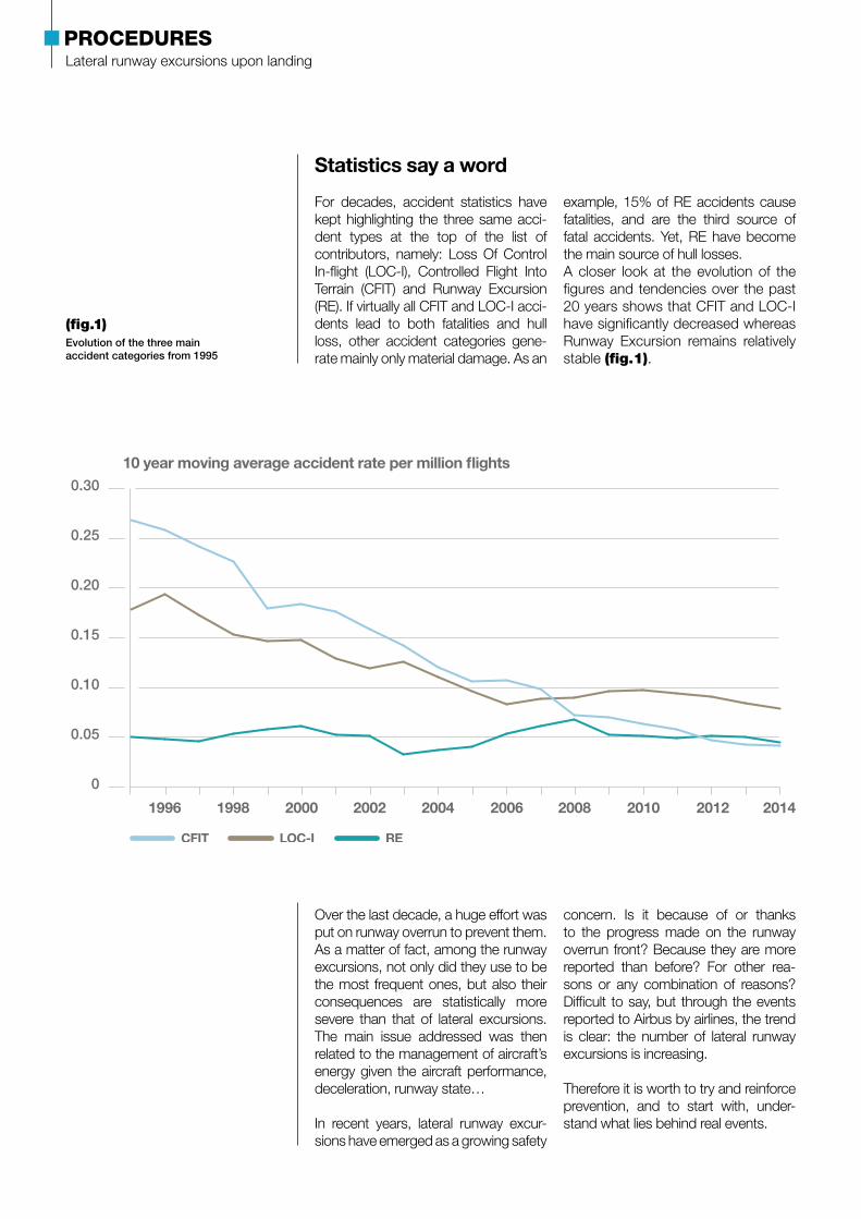
For decades, accident statistics have kept highlighting the three same acci-dent types at the top of the list of contributors, namely: Loss Of Control In-flight (LOC-I), Controlled Flight Into Terrain (CFIT) and Runway Excursion (RE). If virtually all CFIT and LOC-I acci-dents lead to both fatalities and hull loss, other accident categories gene- rate mainly only material damage. As an
example, 15% of RE accidents cause fatalities, and are the third source of fatal accidents. Yet, RE have become the main source of hull losses.A closer look at the evolution of the figures and tendencies over the past 20 years shows that CFIT and LOC-I have significantly decreased whereas Runway Excursion remains relatively stable (fig.1).
Over the last decade, a huge effort was put on runway overrun to prevent them. As a matter of fact, among the runway excursions, not only did they use to be the most frequent ones, but also their consequences are statistically more severe than that of lateral excursions. The main issue addressed was then related to the management of aircraft’s energy given the aircraft performance, deceleration, runway state…
In recent years, lateral runway excur-sions have emerged as a growing safety
concern. Is it because of or thanks to the progress made on the runway overrun front? Because they are more reported than before? For other rea-sons or any combination of reasons? Difficult to say, but through the events reported to Airbus by airlines, the trend is clear: the number of lateral runway excursions is increasing.
Therefore it is worth to try and reinforce prevention, and to start with, under-stand what lies behind real events.
0
0.05
0.10
0.15
0.20
0.25
0.30
2014201220102008200620042002200019981996
(fig.1) Evolution of the three main accident categories from 1995
Lateral runway excursions upon landingPROCEDURES

017Safety First #20 | July 2015
Thanks to airlines support, 31 in-ser-vice lateral runway excursion events were reported to Airbus over a 2012-July 2014 period. A first analysis with a prevention objective in mind led to distinguish between several lateral runway excursions categories due to there being a variety of issues identi-fied and therefore, a variety of potential corrective actions.
Within the defined scope of lateral runway excursion upon landing, 25 events from the initial 31 were consid-ered as relevant and usable.
Of course, the events studied were only those reported to Airbus and therefore, they represented a limited sample. However, they were corrobo-rated by a study of the lateral runway excursion events reported to Airbus from 2007, making the sample much
bigger and the results more robust.
They were studied with a main question in mind: is there a global or common signature for these events that could allow us to learn some generic preven-tion lessons? Interesting insights could be drawn from this work as we shall see later.
When searching for common contrib-uting factors, two main families came out:- weather environmental conditions- flying technique
These two aspects were found in a number of events, most of the time in combination with one another, but with variations as to their detailed nature. A closer look at these two fields allowed for refining the understanding of the underlying phenomena.
WHEN REALITY HELPS SHAPE THE SCOPE TO CONSIDER: AFTER TOUCH-DOWN, YES, BUT NOT ONLY…

Weather environmental conditions
Three main environmental factors came out of the analysis:- Runway state, wet or contaminated- Turbulences or cross-wind- Visibility deterioration
22 events out of 25 analyzed involved a wet or contaminated runway. In 19 out of the 25, there were at least two of the aforementioned environmental factors in the situation (fig.2).
Visibility deterioration (12)
Turbulences or Crosswind (12)
Dry runway (3) Wet or Contaminated runway (22)
A330-A340- A350 Family / A380
A320 Family
Lack of control of the lateral trajectory before Touch Down
Contaminated (SNOW or FLOODED)
(fig.2) Categorization of RE events according to contributing weather conditions factors
Lateral runway excursions upon landingPROCEDURES

019Safety First #20 | July 2015
Lack of control of the lateral trajectory before Touch Down (12)
No or insufficient decrab before Touch Down (7)
Poor control on ground (13)
High approachspeed (1)
Awareness Problembefore Touch Down (1)
A330-A340- A350 Family / A380
A320 Family
Visibility deterioration
Long flare (Δt ≥ 8s)
Flying technique
Regarding the flying technique in the environmental conditions mentioned earlier, three areas were identified as contributing factors to the events occurrence:- Control of the lateral trajectory before
touch-down- Flare and decrab before touch-down- Ground control
In some situations, as illustrated in (fig.3), there was a combination of them.
A major outcome of the analysis is the significant contribution of the air-phase, before touch-down, to lateral runway excursions.
The next question, and more precisely, THE question is: With these insights from real events, how to enhance pre-vention of lateral runway excursions? If there is nothing we can do to change environmental conditions, it seems worth going back to some operational best practices.
(fig.3) Categorization of RE events according to contributing flying technique factors
Lateral runway excursions upon landingPROCEDURES
As stated earlier, handling issues turn out to be a significant contributor to lateral runway excursion events upon landing, especially under some difficult environmental conditions such as wet or contaminated runway or cross wind or turbulence.
What is the appropriate landing tech-nique and why? Let’s prepare for land-ing and review the technique, including some explanations behind the scene, with a special focus on the conditions that were highlighted by the lateral run-way excursion events analysis.
Landing technique: general principles
The appropriate landing technique, what-ever the weather conditions, is a “whole” that combines a variety of dimensions:
information and awareness (e.g. environ-mental conditions), state of mind & pre-paredness and handling skills.
1/ Before flare
Be aware of the landing conditions
If landing with crosswind or on a con-taminated runway rely on specific techniques, the first thing to make sure of is that:- the crosswind, if any, is and remains
within the limits of the aircraft- the runway state allows for a safe
landing and the runway braking coef-ficient is known.
Be correctly seated
During cruise, sometimes a long one, pilots may move their seat a bit. Yet, upon landing, the full deflection of all flight control and braking may be needed to control the situation. There-fore, make sure the pilot seat is in a position (both horizontally and vertically) to allow for those full deflections should they be necessary. This is a key prelim-inary condition to a safe landing.
Be stabilized
In a number of events, there was a localizer deviation away from the centerline. Beyond the lateral control before touch-down, it is essential that the aircraft be on the correct lateral and vertical flight path at the correct configuration and speed up to the initi-ation of the flare.
Be Go-Around minded, as long as needed
Experience shows that some pilots are increasingly reluctant to initiate a go-around as the aircraft gets closer to the ground, even if the aircraft is not well aligned with the runway. Neverthe-less, from a safety viewpoint, initiating a go-around close to the ground or even after a bounced landing is always better than performing an unsafe landing.
2/ From flare to touch-down
Use proper flare and decrab (if needed) flying techniques
Landing in the correct zone, with the right alignment and at the right energy level is a good summary of what a pilot should aim at. Easier said than done?
In the case of crosswind, this requires specific techniques that will be detailed in the next section in this article.
PREVENTING LATERAL RUNWAY EXCURSIONS UPON LANDING: BEST OPERATIONAL PRACTICES
Be stabilized until the flare. If not, go-around.
As long as reversers are not selected, a go- around is always possible.

021Safety First #20 | July 2015
3/ After touch-down
“Fly” until you vacate the runway
Do not relax immediately after touch-down. There is still work to do.
A number of lateral runway excursions resulted from poor ground control in the rollout phase. This is obviously more often the case when a crosswind
makes the day more difficult. Indeed, a number of physical phenomena come into play requiring specific actions to be managed. More details about these phenomena and how to main-tain ground control with crosswind is provided in next section in this article.
Landing with crosswind
As general principles, the landing technique mentioned earlier remains valid. However, it is worth getting a bit further into details and background explanations when crosswind is in- volved in the landing conditions such as those underlined hereafter:- Be aware of the landing conditions- Be correctly seated- Be stabilized
- Be go-around minded as long as needed
- Use proper flare and decrab flying techniques
- “Fly” until you vacate the runway
Let’s examine how these three princi-ples translate into practice in case of crosswind … and why.
Be stabilized
In crosswind situations, the major difference in technique lies in how to keep the aircraft on the correct lateral flight path. In order to do so, it is nece- ssary to fly a wings level and crabbed
approach to correct for the crosswind component on the final trajectory to the runway. Adopting a crab angle allows the pilot to keep the aircraft tra-jectory along the runway axis (fig.4).
(fig.4) Aircraft attitude during a crabbed approach
Crab angle
Runway axis
A CRABBED APPROACH
Lateral runway excursions upon landingPROCEDURES
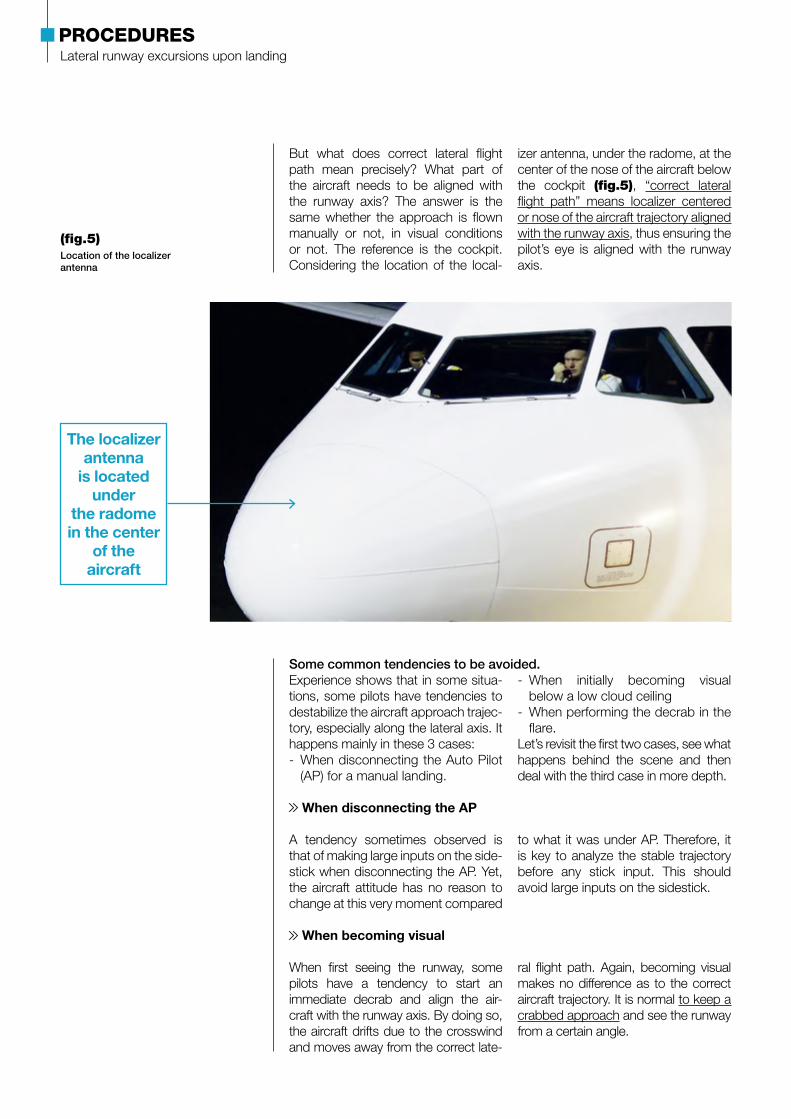
But what does correct lateral flight path mean precisely? What part of the aircraft needs to be aligned with the runway axis? The answer is the same whether the approach is flown manually or not, in visual conditions or not. The reference is the cockpit. Considering the location of the local-
izer antenna, under the radome, at the center of the nose of the aircraft below the cockpit (fig.5), “correct lateral flight path” means localizer centered or nose of the aircraft trajectory aligned with the runway axis, thus ensuring the pilot’s eye is aligned with the runway axis.
Some common tendencies to be avoided.Experience shows that in some situa-tions, some pilots have tendencies to destabilize the aircraft approach trajec-tory, especially along the lateral axis. It happens mainly in these 3 cases:- When disconnecting the Auto Pilot
(AP) for a manual landing.
- When initially becoming visual below a low cloud ceiling
- When performing the decrab in the flare.
Let’s revisit the first two cases, see what happens behind the scene and then deal with the third case in more depth.
When disconnecting the AP
A tendency sometimes observed is that of making large inputs on the side-stick when disconnecting the AP. Yet, the aircraft attitude has no reason to change at this very moment compared
to what it was under AP. Therefore, it is key to analyze the stable trajectory before any stick input. This should avoid large inputs on the sidestick.
When becoming visual
When first seeing the runway, some pilots have a tendency to start an immediate decrab and align the air-craft with the runway axis. By doing so, the aircraft drifts due to the crosswind and moves away from the correct late-
ral flight path. Again, becoming visual makes no difference as to the correct aircraft trajectory. It is normal to keep a crabbed approach and see the runway from a certain angle.
(fig.5) Location of the localizer antenna
The localizer antenna
is located under
the radome in the center
of the aircraft

023Safety First #20 | July 2015
Use proper flare and decrab flying techniques
Flare
If the flare technique is not modified by the presence of crosswind, some aspects need to be particularly kept in mind in such situations, especially:- A high or extended flare significantly
increases the landing distance, whereas, due to possible adverse reversers effects explained later in this article, it is even more important than usual to keep as much runway length as possible to decelerate after touch-down.
- In case of an extended flare, the decrease in the aircraft energy will make it even more sensitive to cross-wind. Counteracting crosswind becomes more and more difficult as speed decays in the flare. Eventually, the crosswind may move the aircraft away from the centerline.
In summary, flare at normal height and do not look for a kiss landing.
Decrab
As mentioned earlier, keeping a crabbed approach is the only way to keep the aircraft on the correct lateral flight path. However, before touch-down, the air-craft needs to be decrabbed to align with the runway axis. The aircraft is to be decrabbed at the time of the flare, using the rudder.
However, it is worth going into further
detail to better understand what results from this action on the rudder. Indeed, when doing so, the aircraft will move a bit towards the wind. Why is it so?In fact, when pushing on the rudder, the aircraft will yaw around a vertical axis that is located a bit forward from the CG, the yaw axis. The moment induced will make the aircraft move slightly towards the wind as illustrated in (fig.6).
(fig.6) Forces and moments effects on aircraft during decrab
Airborne, before the decrab
WIND
Ground speed Air speed
Rudder input effects :- Side force on the fin- Yawing moment
WIND
Ground speed Air speed
Moment and force effects:- Rotation around a point
located slightly in front of the Center of gravity
- Sideslip appears
WIND
Sideslip
Lateral runway excursions upon landingPROCEDURES
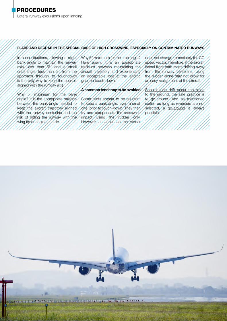
FLARE AND DECRAB IN THE SPECIAL CASE OF HIGH CROSSWIND, ESPECIALLY ON CONTAMINATED RUNWAYS
In such situations, allowing a slight bank angle to maintain the runway axis, less than 5°, and a small crab angle, less than 5°, from the approach through to touchdown is the only way to keep the cockpit aligned with the runway axis.
Why 5° maximum for the bank angle? It is the appropriate balance between the bank angle needed to keep the aircraft trajectory aligned with the runway centerline and the risk of hitting the runway with the wing tip or engine nacelle.
Why 5° maximum for the crab angle? Here again, it is an appropriate trade-off between maintaining the aircraft trajectory and experiencing an acceptable load at the landing gear on touch-down.
A common tendency to be avoided
Some pilots appear to be reluctant to keep a bank angle, even a small one, prior to touch-down. They then try and compensate the crosswind impact using the rudder only. However, an action on the rudder
does not change immediately the CG speed vector. Therefore, if the aircraft lateral flight path starts drifting away from the runway centerline, using the rudder alone may not allow for an easy realignment of the aircraft.
Should such drift occur too close to the ground, the safe practice is to go-around. And as mentioned earlier, as long as reversers are not selected, a go-around is always possible!

025Safety First #20 | July 2015
« Fly » until you vacate the runway
After decrab
When the main landing gear touches the ground with residual crab, a pivot-ing moment is created around a verti-cal axis located at the level of the main landing gear by the combined effect of the lateral friction of the tires on the surface and by the inertia force applied at the center of gravity. This moment tends to turn the aircraft so as to align the aircraft longitudinal axis with the ground speed vector. In short, wheels tend to be more willing to go in the same direction as the aircraft trajec-tory, more than to skid. The intensity of the pivoting moment depends a lot on runway friction.
However, the sideslip coming from the crosswind when the aircraft is decrabbed creates an opposite moment tending to yaw the aircraft
towards the wind direction by weath-ercock effect. Indeed, the effect of the wind on the aircraft fin aligned with the runway axis induces a rotation of the aircraft around a vertical axis located at the CG that yaws the aircraft nose back towards the wind. This opposite moment thus tends to move the air-craft upwind, away from the center-line. It needs to be counteracted by the rudder.
Nevertheless, as the aircraft speed decreases, the rudder efficiency drops. Therefore, the action on the rudder to counteract the weathercock effect needs to be amplified (fig.7). As speed further decreases, the rud-der effect could become insufficient, therefore the pilot must be prepared to apply differential braking.
(fig.7) Counteracting the weathercock effect
On ground, to stay on the runway centerline, a rudder pedal input is necessary. It cancels the weathercock effect mainly due to the fin
Without rudder pedal input, a large yawing moment will make the aircraft turn to the wind
WIND
Sideslip
WIND
Sideslip
WIND
Sideslip
WIND WIND WIND
Lateral runway excursions upon landingPROCEDURES
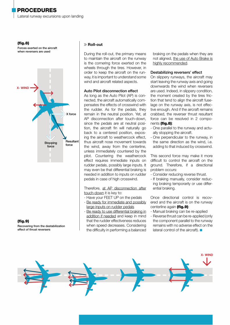
Roll-out
During the roll-out, the primary means to maintain the aircraft on the runway is the cornering force exerted on the wheels through the tires. However, in order to keep the aircraft on the run-way, it is important to understand some wind and aircraft related aspects.
Auto Pilot disconnection effectAs long as the Auto Pilot (AP) is con-nected, the aircraft automatically com-pensates the effects of crosswind with the rudder. As for the pedals, they remain in the neutral position. Yet, at AP disconnection after touch-down, since the pedals are at neutral posi-tion, the aircraft fin will naturally go back to a centered position, expos-ing the aircraft to weathercock effect, thus aircraft nose movement towards the wind, away from the centerline, unless immediately countered by the pilot. Countering the weathercock effect requires immediate inputs on rudder pedals, possibly large inputs. It may even be that differential braking is needed in addition to inputs on rudder pedals in case of high crosswind.
Therefore, at AP disconnection after touch-down it is key to:- Have your FEET UP on the pedals- Be ready for immediate and possibly
large inputs on rudder pedals- Be ready to use differential braking in
addition if needed and keep in mind that the rudder effectiveness reduces when speed decreases. Considering the difficulty in performing a balanced
braking on the pedals when they are not aligned, the use of Auto Brake is highly recommended.
Destabilizing reversers’ effectOn slippery runways, the aircraft may start leaving the runway axis and going downwards the wind when reversers are used. Indeed, in slippery condition, the moment created by the tires fric-tion that tend to align the aircraft fuse-lage on the runway axis, is not effec-tive enough. And if the aircraft remains crabbed, the reverser thrust resultant force can be resolved in 2 compo-nents (fig.8):- One parallel to the runway and actu-
ally stopping the aircraft.- One perpendicular to the runway, in
the same direction as the wind, i.e. adding to that induced by crosswind.
This second force may make it more difficult to control the aircraft on the ground. Therefore, if a directional problem occurs:- Consider reducing reverse thrust.- If braking manually, consider reduc-
ing braking temporarily or use differ-ential braking.
Once directional control is recov-ered and the aircraft is on the runway centerline again (fig.9):- Manual braking can be re-applied- Reverse thrust can be re-applied (only
the component parallel to the runway remains with no adverse effect on the lateral control of the aircraft).
(fig.8) Forces exerted on the aircraft when reversers are used
X- WIND
X force
Stopping force
Resultant force
(fig.9) Recovering from the destabilization effect of thrust reversers
X- WIND

027Safety First #20 | July 2015
Fuel monitoring on A320 Family aircraftSince the first A320 entry into service, very few events have involved undetected fuel quantity issues. Yet, coming across a situation where engines shut down by lack of fuel is a situation no one wants to experience.
Fuel monitoring on A320 Family aircraftOPERATIONS
REGIS PERNETFlight Operations engineer
GÉRALDINE VALLÉEProduct Safety Enhancement manager
ALBERT URDIROZDirector Flight Safety
029Safety First #20 | July 2015
If fuel systems have proven their reliability, in case of failure, the ultimate safety barrier to avoid finding oneself in a fuel critical situation is fuel monitoring by the crew. Let’s go back to some fundamental questions around fuel monitoring on A320 Family aircraft. How to determine the fuel quantity available in the tanks? What are the various sources of information and how redundant are they? Why is it key to perform regular fuel checks?
In more than 25 years of Airbus A320 Family aircraft operation, there have been not more than a handful of events involving undetected fuel quan-tity issues.
The reasons for these fuel quan-tity issues vary from one event to another. Early detection and mana- gement of the issue remains key to successfully deal with such events.
Event 1
During cruise of an A320 Family air-craft, the crew observed 3 occur-rences of the ECAM warning L TK PUMP 1 + 2 LO PR. In line with this warning, they noticed a more rapid fuel level decrease in the left fuel tank compared to the right one. Following the applicable FCOM procedure, they opened the fuel cross feed valve, only to close it soon after as fuel quantity was abnormally decreasing. Minutes later, engine 1 shut down by itself and the ECAM warning ENG 1 FAIL trig-gered.The crew managed to land the aircraft uneventfully with engine 2 still running,
and passengers disembarked safely. The remaining fuel quantity upon land-ing turned out to be 840 kg in the right fuel tank, and no fuel in the left tank.Investigation into this event highlighted that maintenance was done on the fuel tanks prior to the event flight, and both engines 1 and 2 fuel pump filters had been replaced. After the event flight, engine 1 HP fuel pump filter cover was found not properly fitted, with 4 threaded inserts out of 6 being reported unserviceable, thus allowing the cover to partially open. It was esti-mated that approximately 4 to 5 tons of fuel had leaked.
Event 2
In another event, the Fuel Quantity Indication (FQI) system had been showing discrepancies for a period of time. Given the intermittent nature of the fault, entries in the aircraft logbook were investigated but with-out findings by maintenance despite carrying out precautionary mainte-nance. On two occasions, different crews failed to identify or properly record the FOB discrepancy du- ring pre-departure or post-flight fuel checks.
For the event flight, the aircraft departed with an indicated FOB of approximately 5000kg (fuel at arrival from previous leg was approx. 3800kg and fuel uplift was 1200kg). The flight crew performed the initial fuel checks with reference to the fuel logs of the preceding flight. The cal-culated values remained consistent.
In flight, transient fuel quantity fluctu-ations were experienced and eventu-ally the ECAM alert FUEL L (R) WING TK LO LVL triggered. It was pro-
RARE BUT STRIKING EVENTS
Fuel monitoring on A320 Family aircraftOPERATIONS
cessed as per SOP by the crew who checked the SD page as being no- minal. The alert was thus considered spurious. The flight continued with repeated fuel checks at short inter-vals; however during the approach, engine 1 flamed out. Landing was performed on engine 2 safely.After the flight, the left wing tank was
confirmed empty with the FQI over reading by 1 ton.
The analysis of the event indicated that preceding fuel log entries did not allow the crew to identify a significant discrepancy of about 800 kg prior to departure.
Event 3
On the third flight of the day on an A320 Family aircraft, while the aircraft was approaching its destination, a LO LVL alert triggered on one side. The crew considered it spurious, as likely resulting from fuel movement in the tank. Shortly after this first alert, a new LO LVL alert triggered on the other side. The crew continued the flight and eventually landed uneventfully. The remaining fuel quantity upon landing turned out to be approximately 900 kg.During the first flight of the day, the flight crew calculated a ~500 kg dis-crepancy at arrival. Nothing was men-tioned in relation to fuel in the log book.
During the second flight of the day, the discrepancy calculated by the crew at arrival was almost 3000 kg. The First Officer noticed that it was not what he had expected but considered that they had benefited from a number of favora-ble factors such as a direct ATC rou- ting, and they eventually had arrived 20 to 25 minutes earlier than sched-uled. In addition, they sometimes ferry fuel according to the company policy. As a consequence, nothing unusual was mentioned in the log book.Before the third flight - which was the event flight - the refueler only added little fuel since there was still a fuel over read. Yet, the flight crew

031Safety First #20 | July 2015
Considering the consequences of running out of fuel in flight, knowing how much fuel is available on board during the flight is clearly essential to safety. What information can be used to determine the amount of fuel on board? How is this information esta- blished? Do the various pieces of
information relate to one another? Are they independent? Let’s explore the various types of onboard fuel information that are available to the flight crew. Where does this infor-mation originate and how are fuel levels established on Airbus A320 Family aircraft?
HOW MUCH FUEL IS AVAILABLE ONBOARD?
(fig.1) FUEL System page on Lower ECAM Display Unit
The low level sensing does not appear on the System Description page. Therefore, for fuel indication, do not rely on SD page only.
INFORMATION
Each engine is equipped with Fuel Flow Meters that measure the quantity of fuel consumed by the engine. This infor-
mation is integrated by the FADEC and provides pilots with information on the fuel used.
In addition to the sensors and probes feeding the FQI system, each wing tank is equipped with
three independent dedicated low level sensors. These sensors are located in such a way that they
FQI or Fuel Quantity Indication: a source based on measures performed inside fuel tanksThe FQI system calculates the fuel quantity based on values taken from probes in the tanks. The probes meas-ure the level of the fuel in the tank, as a consequence of changing capaci-tance due to the amount the probe is immersed. This allows the determina-tion of the fuel volume in the tank.
Yet the information that is needed by pilots is the quantity of fuel on board expressed as a weight. The translation of fuel volume into fuel weight is performed by the FQIC using the fuel density measured by specific devices in each wing tank (fig.1).
departed with a significantly over-estimated fuel quantity that ulti-mately led to the unanticipated LO LVL alerts on both sides. According to the investigation, the issue/over-
read was due to an intermittent FQI Computer (FQIC) failure. The mainte-nance record of this FQIC highlighted numerous returns to the shop in the months preceding the event.
Fuel Flow Meters: a source based on engines consumption
Low level sensors: an additional independent source based on dedicated sensors in the wing tank
Fuel monitoring on A320 Family aircraftOPERATIONS
The presence of water in the fuel tanks can lead to erroneous (over reading) fuel indi-cations. The parameters used by the fuel system (density and capacitance) are highly affected by the presence of water. Flight deck effects of a buildup of water in the fuel tanks include fuel gauging fluctuations and over reads.
Consequently, among the maintenance tasks that are to be performed if pilots detect an ab-normal fuel indication during a fuel check is fuel tank draining (fig.3). This can also help to pre-vent microbiological contamination, which is often another cause of fuel gauging fluctuations.
INFORMATION
The low level sensors are fully independent from the Fuel Quantity Indication.
An unnecessary burden or essential safety net?Ensuring an accurate awareness of the quantity of fuel on board requires use of several sources of data. Cer-tainly the FQI is the primary source of fuel indication, but the other key sources such as the Fuel Used, the fuel uplifted at the latest refuel, the crosscheck between what is expected to be uplifted and what is uplifted, information from the refue-
ler and fuel consumption figures during flight, are all important. But to ensure the information remains accurate, the safety barrier com-mon to all cases is fuel monitoring by the crew.
Although fuel checks with the manual calculations they involve can some-times be perceived as a tedious task,
FUEL CHECKS (fig.3) Maintenance Planning Document – ATA 28 Fuel – Task 281100-01-2 – Drain water content in tanks
The A320 Family aircraft low level indication is based on remaining fuel quantity in the tank being sufficient to meet the requirement of 30 minutes at 1500 ft (corresponding to approximately 1 200 kg). Should the low level alert trigger on both fuel tanks, the total remaining fuel is: 750kg + 750kg = 1 500 kg.
DID YOU KNOW
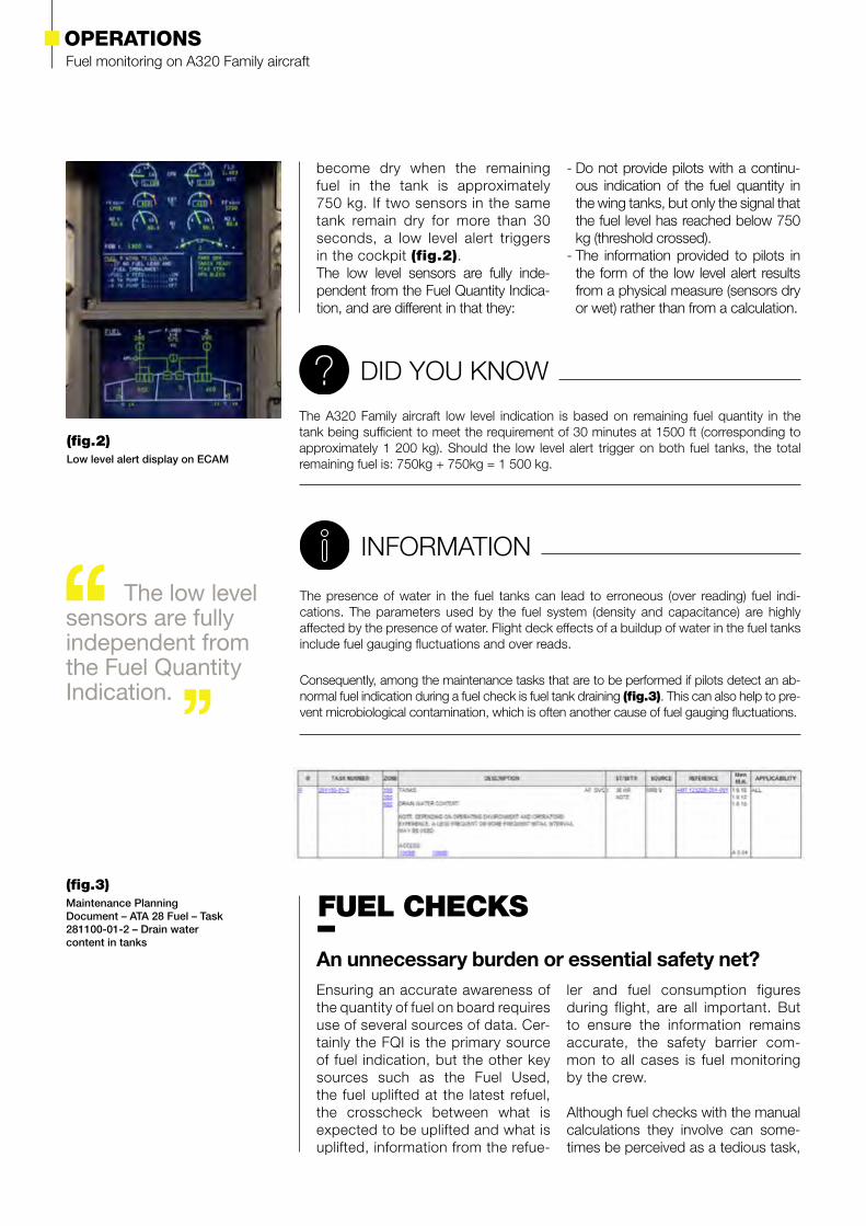
become dry when the remaining fuel in the tank is approximately 750 kg. If two sensors in the same tank remain dry for more than 30 seconds, a low level alert triggers in the cockpit (fig.2).The low level sensors are fully inde-pendent from the Fuel Quantity Indica-tion, and are different in that they:
- Do not provide pilots with a continu-ous indication of the fuel quantity in the wing tanks, but only the signal that the fuel level has reached below 750 kg (threshold crossed).
- The information provided to pilots in the form of the low level alert results from a physical measure (sensors dry or wet) rather than from a calculation.
(fig.2) Low level alert display on ECAM
033Safety First #20 | July 2015
The fuel available onboard can be determined based on two independent sources of information… even three in case of low level.
Initial Fuel On Board (FOB) + Fuel Uplifted = Fuel On Board (FOB) ± Δ
WhereFOB is the fuel quantity derived from the FQI systemFuel Uplifted is the amount of fuel indi-cated by the refueler as having been added during refueling. This may require converting volume into weight,
based on the uplifted fuel density.Δ is an acceptable tolerance (see Why do we need to consider a cer-tain tolerance on fuel onboard val-ues? insert).
they form in reality an integral part of the measures taken to ensure safe operations. They were designed and meant for detecting as early as pos-sible any fuel quantity issue, ensur-ing timely and accurate maintenance intervention, and allowing appropri-
ate measures to secure the safety of the flight. They are applicable to all Airbus Families aircraft from the first A300B to the latest A350, and remain an essential part of airmanship when piloting the A320 Family aircraft.
What is to be checked and when?
The maximum efficiency of fuel checks relies on the flight crew per-forming a number of checks regu-
larly and at different times to either confirm anticipations, or detect any discrepancy.
Before start
The first fuel check to be performed is before start to consolidate the infor-mation about the total amount of fuel
available for the flight. This check con-sists in making sure that:
During the flight
During the flight, fuel checks mainly aim at detecting any abnormal con-sumption, be it due to a leak or unan-ticipated drag (e.g. spoiler or landing gear, slats or flaps not fully retracted) or any other reason.Indeed, such situation would make
the FMS fuel predictions too optimis-tic and potentially lead to fuel exhaus-tion in flight. To ensure that there is no undetected fuel leak, the following calculation should be performed at each way point or every 30 minutes:
Fuel On Board (FOB) + Fuel Used = Initial Fuel On Board (FOB) ± Δ
WhereFuel Used is derived from the fuel flow metersIn addition, the remaining FOB and Fuel Used values must also be consistent with the values given by the computed flight plan at each waypoint.
Fuel monitoring on A320 Family aircraftOPERATIONS
WHAT IF A FUEL CHECK IS MISSED?
Depending on the underlying reason for a fuel quantity issue, missing a fuel check may make it very difficult to detect. In the second event described, the failure of the Fuel Quanti-ty Indication Computer did not lead to a systematic wrong indication but rather to quantity fluctuations. The fuel quantity indicated by the FQI system before the first flight of the day was correct. In such cases, skipping a fuel check may be a missed opportunity to detect a failure that may not be detectable later on, at the time of the following check. More gener-ally, whatever the origin of a fuel quantity issue, detecting it as early as possible allows for managing it and making sure appropriate decisions can be made in time to best manage the rest of the flight as safely and efficiently as possible.
NOTE
WHY DO WE NEED TO CONSIDER A CERTAIN TOLERANCE ON FUEL ON BOARD VALUES?
Due to the nature of the fuel system, it is essential that the system tolerance be taken into consideration when performing fuel quantity calculations. The overall FQI system accuracy is designed to take into consideration several factors such as: attitude effects, wing deformation, systems tolerances, manufacturing tolerances, component toleranc-es, environmental effects, fuel characteristics.These individual tolerances lead to an overall tolerance on the global system resulting from the worst case (maximum tolerance) on each individual element.
The maximum tolerance is defined for the aircraft to guarantee an acceptable level of integrity of the measure and the associated fuel quantity information. When a fuel check is performed, any fuel discrepancy calculated by the crew and exceeding this value may then be considered abnormal.
For an A320 Family aircraft, the instrumental tolerance on the ground is calculated as follows:
± (1% of current FOB + 1% max possible FOB for this aircraft)
As an illustration, for an A320 aircraft, if there are 5 tons left in the aircraft, the maximum nor-mal tolerance value is:
± (5000kg (current FOB) * 1% + 20000kg (max FOB)* 1% ) = ± 250kg
Note: The FQI system is designed in such a way that the lower the fuel quantity in the tank, the more accurate the fuel indication.
The FQI system is calibrated on ground during manufacturing and its accuracy (as per the formula above) will remain the same throughout the operational life of the aircraft.
Post flight
At the end of the flight, when the air-craft has reached its parking stand, a final fuel check is to be performed to check the consistency between the information provided by the var-
ious sources and thus detect any abnormal discrepancy that would call for maintenance actions. The post flight fuel check consists of making sure that:
Fuel On Board (FOB) + Fuel Used = Initial Fuel On Board (FOB) ± Δ
All fuel checks are equally important in the detection and safe management of any fuel quantity issue.
035Safety First #20 | July 2015
Following the investigation of real events involving fuel monitoring issues, Airbus identified and implemented enhance-ments in several areas:
• Further refinement of the description of the Fuel Quantity Indicating and level sensing systems in the FCOM doc-umentation. During the interactions with the airlines involved, it turned out that the independence of the two fuel measures coming from respectively the FQI system and the low level alert was not clear to all crews.
• Definition of empirical criteria on A320 Family aircraft to consider a fuel discrep-ancy “abnormal” or “unusual” when performing the before start fuel check. These thresholds will be expressed in
kg or lbs and will vary depending on the fuel on board and fuel uplifted. They will lead to a generic maintenance task in the TSM (Trouble Shooting Manual).
• Service Bulletin A320-28-1214 for A318/A319/A320 and Service Bulletin A320-28-1202 for A321 aircraft intro-duce a new fuel leak detection function, which eases and improves the detec-tion of a fuel leak. This new function is meant to prevent situations where a loss of fuel would remain undetected by the crew.
• A new FCOM evolution will be availa-ble soon, that will describe the trigger-ing conditions of the low level alert in the procedure, and to show that the alert is independent of the displayed fuel.
TO FURTHER ENHANCE SAFETY…
A “GOLDEN RULE” IN THE TROUBLE SHOOTING MANUAL (TSM)Until recently, there was no generic entry into the TSM in case of abnormal fuel quantity. It is therefore worth reminding everyone of a key sentence in the introduction of the TSM that encourages airlines to manage cases where there may be a doubt as to the aircraft airworthiness:“If you cannot find a fault symptom and/or a fault isolation procedure necessary to en-sure the continued airworthiness of the aircraft, or if you think that the information given is not complete, contact Airbus”.
DID YOU KNOW
An engine failing in flight, because of fuel starvation, is a situation all pilots would like to avoid. In order to do so, and to ensure the continuing accu-racy of the FQI, performing thorough fuel checks before start, throughout the flight and after arrival at the parking stand is essential.
Should any discrepancy appear, effectively tackling the underlying issue, be it intermittent or permanent, is the only way to prevent further fuel quantity indication and possible resulting safety issues. This relies on good cooperation between flight crews, maintenance and the manufacturer.
Should the LO LVL alert trigger , it is to be trusted! It is the independent voice from the tanks themselves warning you …

Safety First #20 | July 2015036
“Had I not known this, under-stood that or paid attention to that, I wouldn’t be here with you today” was a sentence Jacques often repeated when he referred to some of the thousands of flights he performed either as a fighter pilot or as an experi-mental test pilot. Sadly, Jacques is no longer with us today. He was a genius pilot, a humble man, a great man. Aviation was his passion, safety his quest. He was always ready to share his knowledge, experience and wisdom to improve safety, as he did with the following article.
HE WILL BE MISSED…

037Safety First #20 | July 2015
High-altitude manual flyingFlying an aircraft manually at high altitudes, and therefore necessarily at high Mach number, is a completely different discipline to what it may be like at low altitudes. As it turns out, opportunities to experience manual flying at high altitudes are rare in a pilot’s career. Yet, regulations do require it in certain circumstances, such as when the Auto Pilot is unavailable.
JACQUES ROSAYExperimental Test PilotFormer Airbus Chief Test Pilot
High-altitude manual flyingGENERAL TOPIC

Most of the time, commercial aircraft fly at high altitudes, above FL 290. In other words, they fly within the RVSM (Reduced Vertical Separation Minima) space that extends from FL 290 to 410 included, and which now covers a very large part of the world’s airspace. As it turns out, use of the Auto Pilot (AP) within this airspace is mandatory, meaning that the regulations actually prevent the pilots from acquiring practical manual flying experience of their aircraft within the part of the envelope where they most often fly.
Pushing this paradox further, in certain cases, especially if the AP is unavailable, these same regulations require that the pilots manually fly the aircraft to rapidly leave this airspace in coordination with air traffic control. In other words, pilots are requested to do maneuvers for which practicing in flight is prohibited.
However, the behaviour of an aircraft at high altitude is significantly different from that of an aircraft at low and medium altitudes.
The aim of this article is to recall some qualitative aerodynamic, flight mechanics and handling qualities notions specific to the high Mach numbers and to high altitudes, to share practical experiences lived by Airbus test pilots in these domains and to make suggestions for training. Lastly, note that, apart from passages specifically dedicated to the normal and alternate electrical flight control laws, the whole of this article applies to all types of commercial aircraft whether equipped with electrical flight controls or not.
The effects of Mach number
The air flow around the wings accel-erates on the upper surface creating a negative pressure and it is this nega-tive pressure which mainly keeps the aircraft up (fig.1).
When the altitude increases and the air density falls, more aerodynamic speed is required to create the lift required for a given lift configuration. This reduc-tion in the density and this increase in the aerodynamic speed is accompa-nied by an increase in the Mach num-ber required for flight. We have seen that by passing over the wings, the
air flow accelerates on the upper sur-face. Therefore, the local Mach number around the wings is much higher than the aircraft flight Mach number and in certain locations reaches transonic values. In high-altitude stabilised flight, shock waves can be seen at certain locations by looking at the upper sur-face through the cabin windows.
This sonic phenomenon around the wings leads to a degradation of their aerodynamic properties. This, in turn, leads mainly to a reduction in the maximum lift angle of attack as the
AERODYNAMIC ESSENTIALS
(fig.1) Air flow around an airfoil
039Safety First #20 | July 2015
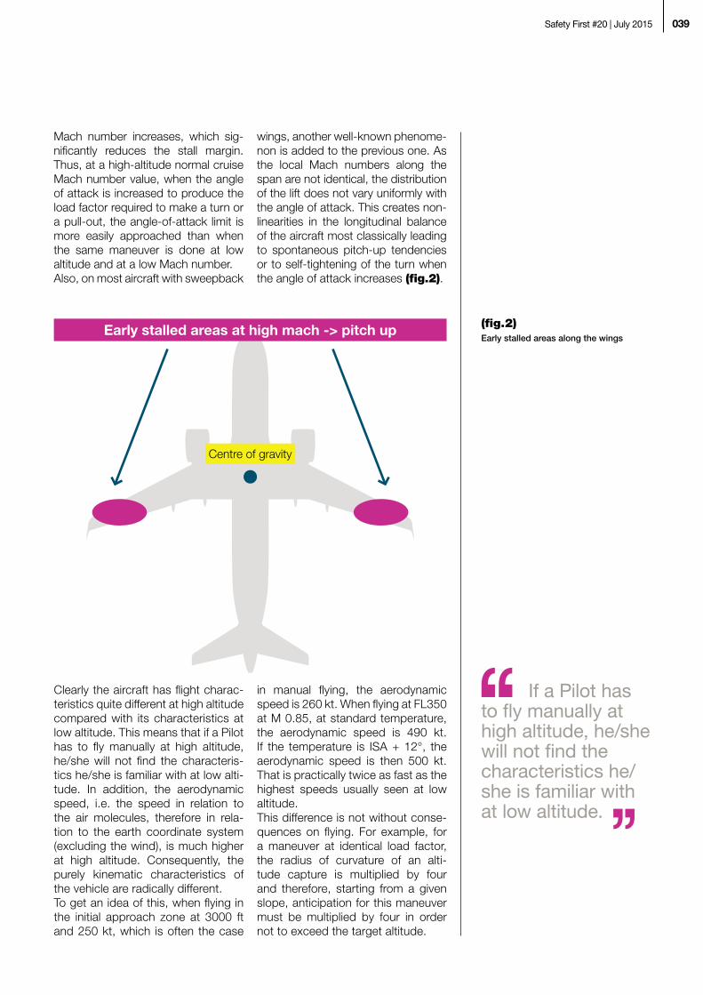
Mach number increases, which sig-nificantly reduces the stall margin. Thus, at a high-altitude normal cruise Mach number value, when the angle of attack is increased to produce the load factor required to make a turn or a pull-out, the angle-of-attack limit is more easily approached than when the same maneuver is done at low altitude and at a low Mach number. Also, on most aircraft with sweepback
wings, another well-known phenome-non is added to the previous one. As the local Mach numbers along the span are not identical, the distribution of the lift does not vary uniformly with the angle of attack. This creates non-linearities in the longitudinal balance of the aircraft most classically leading to spontaneous pitch-up tendencies or to self-tightening of the turn when the angle of attack increases (fig.2).
Clearly the aircraft has flight charac-teristics quite different at high altitude compared with its characteristics at low altitude. This means that if a Pilot has to fly manually at high altitude, he/she will not find the characteris-tics he/she is familiar with at low alti-tude. In addition, the aerodynamic speed, i.e. the speed in relation to the air molecules, therefore in rela-tion to the earth coordinate system (excluding the wind), is much higher at high altitude. Consequently, the purely kinematic characteristics of the vehicle are radically different.To get an idea of this, when flying in the initial approach zone at 3000 ft and 250 kt, which is often the case
in manual flying, the aerodynamic speed is 260 kt. When flying at FL350 at M 0.85, at standard temperature, the aerodynamic speed is 490 kt. If the temperature is ISA + 12°, the aerodynamic speed is then 500 kt. That is practically twice as fast as the highest speeds usually seen at low altitude. This difference is not without conse-quences on flying. For example, for a maneuver at identical load factor, the radius of curvature of an alti-tude capture is multiplied by four and therefore, starting from a given slope, anticipation for this maneuver must be multiplied by four in order not to exceed the target altitude.
Early stalled areas at high mach -> pitch up
Centre of gravity
(fig.2) Early stalled areas along the wings
If a Pilot has to fly manually at high altitude, he/she will not find the characteristics he/she is familiar with at low altitude.

High-altitude manual flyingGENERAL TOPIC
Compressibility stall
We have seen that when the Mach number increases, the maximum lift angle-of-attack is reduced (fig.3).
We can imagine that at a certain point in the increase of the Mach, the angle-of-attack can theoretically be so lim-ited that the maximum lift the wings are capable of producing becomes insufficient to sustain the weight of the aircraft. In certain aerodynamic manu-als, this theoretical point is called the “compressibility stall”.It depends on the evolution of the curve lift versus Mach. This change depends on many aerodynamic chara- cteristics of the aircraft, such as the wing profile, the chord, the sweep, the span, etc. Remember that this phenomenon does not exist on an aircraft where the wings are designed
for flight at supersonic speeds. Pilots who have flown on the T33 or the Alpha Jet may perhaps remember having reached subsonic Mach num-bers beyond which the wings were incapable of providing a load fac-tor of 1 g. Level flight could not be maintained: compressibility stall was reached. The Mach number had to be reduced to regain the load factor authority required for straight level flight. On the Alpha Jet in particular, with a little patience and a very small amount of fuel on-board, it is even possible to climb to an altitude where it was neither possible to decelerate due to low Mach number stall nor to accelerate due to compressibility stall. There was only one single practicable flight point: the aerodynamic ceiling was reached.
Mach
α Stall
(fig.3) General tendency in the evolution of the maximum angle-of-attack (α) versus the Mach number
Aerodynamic ceiling and buffeting margin
In practice, even if the compressibili- ty stall and the aerodynamic ceiling can theoretically exist in aerodyna- mics in certain cases, they cannot be reached by a certified commercial air-craft and this for several reasons. Let us see why.
1) The certification regulations require that throughout the flight envelo- pe, up to MMO, irrespective of the weight, the aircraft must have a buf-feting margin of 0.3 g.This means that a load factor of 1.3 g must be attainable before “buffet onset” is encountered. “Buffet onset”
is defined such that when an accelero- meter located under the pilot’s seat measures peak-to-peak accelera-tions higher than 0.1 g. Therefore, the aircraft MMO value and the lift ceiling (which depends on the weight) are by definition such that there is always a buffeting margin of at least 0.3 g and therefore, a margin well above the compressibility stall is ensured.
2) The certification regulations also require that the flight tests check that the aircraft can fly above MMO up to MD.MD is the highest Mach number at

041Safety First #20 | July 2015
which the aircraft must be able to fly without structural anomalies (this is the flutter margin) and without substantial degradation in the handling qualities allowing the aircraft to be always easily controlled. It is determined by cali-brated maneuvers (FAA dive, JAA dive) defined by the certification regulations. In practice, typically MD = MMO + 0.06.
To conclude, the regulatory criteria related to the buffeting margin at MMO and to the flight characteristics up to MD imply that the “compressibility stall” and “aerodynamic ceiling” phe-
nomena cannot be physically encoun-tered due to the design of the aircraft. “Compressibility stall” does not exist on current commercial aircraft.
DETERMINING MD IN FLIGHT TESTS
During the flight test, MD must be reached fairly quickly by an accentuated dive before encountering another limit: the absolute speed limit VD (typically VD = VMO + 35 kt), which is approached as the altitude drops. For this, Airbus test pilots start from the aircraft ceiling, in direct law, at a Mach as close to MMO as possible. Then they accelerate by a dive with an attitude of around -15° at the start of the maneuver with engines at full throttle. When MD is reached, this Mach is maintained by adjusting the
pitch attitude and then, the structure is excited by programmed impulses into the flight controls. The purpose of this is to check that there are no divergent structure oscillations (flutter). Then, test pilots do a positive pull-out, engines idling, to return to the normal flight envelope. This pull-out requires an important increase in the load factor and demonstrates that compressibility stall is still far from being reached. However, the buffeting margin of 0.3 g is no longer observed beyond MMO and approach of MD at n = 1 is in reality
done with moderate buffeting, but the aircraft can still be controlled and maneuvered. Beyond MD, the structural integrity of the aircraft is no longer ensured! Based on the experience accumulated at Airbus and seeing how many aircraft still respond very well at MD load factor, very serious structural problems will be encountered before finding a possible compressibility stall which, if it exists, can be found only at Mach numbers well above MD, probably above Mach 1.
Definition
It would be interesting to survey pilots as to what they understand by the terms “flying manually”. Per-sonally, I have often heard during test, demonstration, acceptance or airline flights, colleagues, young or older, airline pilots or test pilots, proudly say that they would do such or such a part of the flight - in gen-eral a complete approach followed by a landing - “in manual control mode”. I would then observe how they performed and saw that all they did was actually disconnect the AP and servilely follow the Flight Direc-tor, leaving the Auto Thrust engaged. And this until start of the flare. This
obviously allows an accurate trajec-tory to be followed, with correct cap-tures, and good control of the speed. These functions are provided for this purpose. However, within the scope of this arti-cle, which concerns manual flying, flying in this manner can in no way be considered as “flying manually”. Indeed, the orders given to the flight controls by the pilot consist in setting the Flight Director (FD) bars to zero, which corresponds to the orders generated by the guidance function. These stick inputs are actions done mechanically by the pilot but are in no way elaborated by him/her. These
FLYING MANUALLY

High-altitude manual flyingGENERAL TOPIC
flight control orders are the same as those which the AP would give if it was engaged. Thus, the added value provided by the pilot is rather nega-tive, as the cognitive resources that he/she uses to follow the FD bars are no longer available for the most elaborate flight monitoring and con-trol functions. In other words, this exercise provides strictly nothing towards the manual flying training for the cases where the pilot would truly have to fly the aircraft manually.
The terms “flying manually” in this article imply that the guidance func-tions have become unavailable, pos-sibly with the flight control laws in a degraded mode. In this configuration, pilots must be
able to correctly perform, at any alti-tude, all the maneuvers required to manually control the aircraft and land it under satisfactory safety conditions. These safety conditions would not be met if a pilot is not at ease when per-forming, under all flight control condi-tions which may be encountered fol-lowing failures, manual flying without the FD, without the ATHR and without speed vector, from the cruise ceiling of the aircraft to instrument landing under CAT1 weather conditions. The type certifications of all the commercial aircraft in the world are established by the Authorities on the fundamental hypothesis that any qualified pilot is capable of meeting this requirement.
Specificities of flight control laws
We have seen that the rules appli-cable for RVSM mean that the situa-tions where the aircraft must be flown manually at high altitude are limited to degraded cases, especially cases where the AP is lost and, possibly, where the normal law is also lost. As the aim of this article is to get a better knowledge of these situations, let us look at the specificities of the high-al-titude flight control laws. As said earlier, compared to low alti-tude, the high aerodynamic speeds used at high altitude radically change the trajectories followed for given load factor applications. This means that
the pilot must anticipate to a greater extent the changes in the trajectories both vertically and horizontally. This is valid whatever the flight control law used, including the normal law.The behaviour of the normal law differs from its behaviour at low alti-tude by the effect of the speed on the trajectory. This is sufficient to make it worth the effort to become familiar with the situation in the sim-ulator. For degraded laws, or for aircraft with conventional flight con-trols, the characteristics specific to high altitude are more affected and must be known.
Normal and alternate laws
The normal law and the alternate law - so-called C* laws, or load factor flight control laws - function practically identically on the longitudinal axis as long as we remain within the opera-tional flight envelope and we do not perform dynamic maneuvers leading the angle-of-attack to approach max-imum values (which depend on the Mach number). Beyond these limits, the alternate law no longer ensures the protections and this is recalled by the “protection lost” message on the ECAM. The pull-out and turn
maneuvers, for a given longitudinal stick order, give the same load factor excursion. As the alternate law is not protected against excessive angles of attack, awareness of an approach to limiting angle-of-attack is ensured by the Stall Warning (SW) or, in cer-tain cases, by the deterrent buffeting, to which the pilot must react imme-diately by releasing control. The SW directly alerts the crew of stall proxim-ity but it also indirectly alerts it by indi-cating, during dynamic maneuvers, that it is approaching angles of attack
The pilot must anticipate to a greater extent the changes in the trajectories both vertically and horizontally.
043Safety First #20 | July 2015
To make flying more comfortable, even outside of the RVSM space, when flying in degraded laws, it is recommended to maintain some margin in altitude (around 4000 ft) below the REC MAX altitude.
where the pitch-up phenomenon may start to develop; this phenomenon itself can lead to stall if the pilot does not immediately counter it by reac- ting to the SW. In practice, maneu-vers a little too dynamic can fairly easily lead to the SW, especially if they are done close to the maximum cruise altitude (REC MAX) calculated by the FMS. For this reason and to make flying more comfortable, even outside of the RVSM space, when flying in degraded laws, it is recom-mended to maintain some margin in
altitude (around 4000 ft) below the REC MAX altitude.
According to the type of aircraft and type of failure, the alternate law may lead to lateral control being in direct law, i.e. a deflection of the ailerons according to the stick input and not according to a roll rate law, as is nor-mally the case in normal law. This difference can be fairly significant, generally leading to roll responses a little more sharp than in normal law, but still easy to control.
Direct law
In direct law, as its name implies, the controls give direct orders to the con-trol surfaces. In direct law, the aircraft becomes an “old aircraft” where no assistance is given to the pilot. The longitudinal trim must be used to zero forces on the stick and to balance the longitudinal effects of the engines. The ECAM and the Primary Flight Display (PFD) remind us of this by the “USE MAN PITCH TRIM” message. However, depending on the aircraft, very basic yaw or roll dynamic sta-bilisation functions may be included in the direct law. At high altitude, the trim law versus speed variations, and therefore the Mach number, is very “flat”. Pilots should therefore not be surprised that there is much
less need to use the trim than at low altitude.During flight tests, Airbus test pilots try to adjust the kinematics of the direct law to make it as “placid” as possi-ble at high altitude in all the weight and CG ranges. The aim is to have enough authority to efficiently do the basic maneuvers in the vertical and horizontal planes, but without trying to do specifically dynamic maneu-vers. Here also, as with alternate law, the deterrent buffeting and/or the SW warn against excess angles of attack taking into account, if applicable, a pitch-up tendency. The same recom-mendations also apply concerning the flight altitude.
Representativeness of simulators at high altitudeThe flight mechanics models used on the training simulators are established based on specific tests conducted dur-ing real flights. They generate what is called the “data package. These tests are long and many to obtain a model very close to reality. As I have done several thousands of hours of tests of all sorts on simulators before doing them in flight, I can confidently say that
the models supplied by the simula-tors are very close to reality. However, two important limits exist and must be known, which are the very high angles of attack and the representativeness of the cabin movements.
1) During flight tests, for each type of aircraft, hundreds of stalls are per-formed, beyond the SW and a little
TRAINING FOR HIGH-ALTITUDE MANUAL FLYING

High-altitude manual flyingGENERAL TOPIC
Over the normal operating domain of commercial flying, simulators are perfectly representative of reality and utmost confidence can be placed in them, for both low and high altitude manual flight.
beyond the maximum lift coefficient (Cl) to clearly identify the loss of lift. In practice, the maximum Cl is exceeded by several angle-of-attack degrees, let us say four or five, but not more. This means that all maneuvers on the simulator that go beyond these known values enter a domain where the re- presentativeness of the model becomes erroneous. Therefore, the exercises on the simulator must not go further than the excursions leading to the reactions to the SW which, according to regu-lations, are expected by the pilot. In practice, not more than 3 seconds after the appearance of the SW during a dynamic maneuver in cruise. This obvi-ously concerns only the unprotected laws.
2) The movements of mobile simu-lator cockpits are intended to trick the sensory channels of the pilots to make them believe that what they perceive corresponds to a real flight. This operates fairly well when the si- mulated movements remain low. Sim-ply, let us say that the feelings are not too false whilst the movements of the aircraft are those that the Auto Pilot would command. Whenever signifi-cant dynamic movements are done, the feelings become very false and
can clearly have counterproductive training effects as the pilots then per-ceive sensations contrary to what they would experience in reality. This can be asserted based on a comparison between the basic rotation speed and acceleration parameters on the three aircraft axis (i.e. p, q, r, nx, ny, nz of the flight mechanics) with the same parameters measured in the cockpit of a mobile simulator during somewhat dynamic maneuvers. For this reason, during the flight tests, cockpit move-ments are never used to fine tune the flight controls knowing that the sensa-tions experienced are, essentially false, and can therefore seriously alter test pilots assessment of these.
Clearly these two limits can be consi- dered as such only when certification flight tests maneuvers are performed very close to – if not beyond – the li- mits of the aircraft flight envelope. Over the normal operating domain of com-mercial flying, simulators are perfectly representative of reality and utmost confidence can be placed in them, for both low and high altitudes. For this reason, flying in a simulator is the best option for pilots to experience and train for manual flying at any altitude.
Some ideas for high-altitude manual flying training
Simulation training exercises must show pilots that at high altitudes and high Mach numbers, it is very impor-tant to adopt an especially calm, flex-ible flying attitude without aggressive-ness. At the same time, the exercises suggested here will allow pilots to reinforce the necessary confidence in themselves. To gain this competence, it is important that they do maneuvers which go a little beyond those that they may have to do in flight. Here are several personal ideas of exercises to reach this objective. Within the same frame of mind, others can of course be proposed.
1) Normal law, AP engaged, weight = MLW + 2 hours of fuel consumption, REC MAX altitude and cruise Mach according to airline Cost Index. Loss
of AP, FD and ATHR, return to alter-nate law. Keep level flight. Reduce Mach to alternate law limit (if appli-cable). Do a turn with a bank angle of 30° (that is 1.15 g) in level flight at constant Mach. Resume straight line flight. Descent with engines at idle to first level outside of the RVSM space, still at constant Mach. Tem-porarily stabilise at REC MAX – 4000 ft, maintaining the Mach. Observe the response of the aircraft, resume descent.
2) Normal law, AP engaged, weight = MLW + 2 hours of fuel consumption, REC MAX altitude. Loss of AP, FD and ATHR, return to direct law. Use the trim. Keep level flight. Reduce Mach to direct law limit (if applica-ble). Make a turn with a bank angle

045Safety First #20 | July 2015
of 25° (that is 1.1 g) in level flight at constant Mach. Resume straight line flight. Descent with engines at idle to first level outside RVSM space, still at constant Mach. Temporarily stabilise at REC MAX – 4000 ft, maintaining the Mach. Observe the response of the aircraft, resume descent.
As a passenger, I would be very happy to fly with an airline which gives its pilots the instruction to place them-selves in the easiest situation at all times. Pilots should be instructed to use all the piloting aids placed at their disposal to facilitate their tasks as far as possible. In practice, this perfectly respectable policy leads the pilots to almost never manually fly the aircraft, except on take-off for a short period and for certain landings between the minima and the ground when auto-matic landing is impossible. This means that the pilots of such an air-line acquire or maintain almost no
manual flying training. But, again as a passenger, I at the same time require that these same pilots have all the manual flying skills that we have dis-cussed and which they require to face up to failure cases where the piloting aids are no longer available, whether at high or low altitude. These two requirements are contra-dictory only in appearance. Indeed, even as is the case in many airlines, the pilots are authorised to manually fly aircraft under certain conditions. During commercial flights, they could never fly manually at high altitude due to the RVSM rules, or under degraded flight control laws for obvious reasons, which deprives them of all knowledge of the reactions of their aircraft under these conditions.The only solution to cover this need is therefore the intensive use of training simulators and this in perfect compli-ance with the limits of their represent-ativeness.
At high altitudes and high Mach numbers, it is very important to adopt an especially calm, flexible flying attitude without aggressiveness.

Safety First #20 | July 2015046
ARTICLES PUBLISHED IN PREVIOUS ‘SAFETY FIRST’ ISSUES
Issue 17
January 2014
• Airbus Brake Testing• Hard Landing, a Case Study
for Crews and Maintenance Personnel
• Aircraft Protection during Washing and Painting
• Flight Data Analysis (FDA), a Predictive Tool for Safety Management System (SMS)
• Flying a Go-Around, Managing Energy
Issue 18
July 2014
• Control your speed... at take-off• Safe operations with composite
aircraft• Learning from the evidence• A320 Family cargo Containers/
pallets movement• Parts Departing from Aircraft (PDA)
Issue 19
January 2015
• Tidy cockpit for safe flight• Landing on contaminated
runways• Understanding weight
& balance• Wind shear: an invisible enemy
to pilots?
Issue 16
July 2013
• Performance Based Navigation: RNP and RNP AR Approaches
• Atlantic Airways: Introduction of RNP AR 0.1 Operations
• Flight Crews and De-Icing Personnel – Working together in Temporary Teamwork for safe Skies
• Low Speed Rejected Take-Off upon Engine Failure
• Late Changes before Departure
Issue 15
January 2013
• The Golden Rules for Pilots moving from PNF to PM
• Airbus Crosswind Development and Certification
• The SMOKE/FUMES/AVNCS SMOKE Procedure
• Post-Maintenance Foreign Objects Damage (FOD) Prevention
• Corrosion: A Potential Safety Issue
Issue 14
July 2012
• Thrust Reverser Selection means Full-Stop
• Transient Loss of Communication due to Jammed Push-To-Talk A320 and A330/A340 Families
• A380: Development of the Flight Controls - Part 2
• Preventing Fan Cowl Door Loss• Do not forget that you are not
alone in Maintenance

047Safety First #19 | January 2015
Issue 13
January 2012
• A320 Family / A330 Prevention and Handling of Dual Bleed Loss
• The Fuel Penalty Factor• The Airbus TCAS Alert Prevention
(TCAP)• A380: Development of the Flight
Controls - Part 1• Facing the Reality of everyday
Maintenance Operations
Issue 12
July 2011
• Airbus New Operational Landing Distances
• The Go Around Procedure• The Circling Approach• VMU Tests on A380• Automatic Landings
in Daily Operation
Issue 11
January 2011
• What is Stall? How a Pilot Should React in Front of a Stall Situation
• Minimum Control Speed Tests on A380
• Radio Altimeter Erroneous Values• Automatic NAV Engagement at
Go Around
Issue 10
August 2010
• A380: Flutter Tests• Operational Landing
Distances: A New Standard for In-flight Landing Distance Assessment
• Go Around Handling• A320: Landing Gear Downlock• Situation Awareness and Decision
Making
Issue 8
July 2009
• The Runway Overrun Prevention System
• The Take-Off Securing Function• Computer Mixability:
An Important Function• Fuel Spills During Refueling
Operations
Issue 9
February 2010
• A320 Family: Evolution of Ground Spoiler Logic
• Incorrect Pitch Trim Setting at Take-Off
• Technical Flight Familiarization• Oxygen Safety

Safety First #20 | July 2015048
Issue 2
September 2005
• Tailpipe or Engine Fire• Managing Severe Turbulence• Airbus Pilot Transition (ATP)• Runway Excursions at Take-Off
Issue 3
December 2006
• Dual Side Stick Inputs• Trimmable Horizontal Stabilizer
Damage• Pitot Probes Obstruction
on Ground• A340: Thrust Reverser Unlocked• Residual Cabin Pressure• Cabin Operations Briefing Notes• Hypoxia: An Invisible Enemy
Issue 1
January 2005
• Go Arounds in Addis-Ababa due to VOR Reception Problems
• The Importance of the Pre-flight Flight Control Check
• A320: In-flight Thrust Reverser Deployment
• Airbus Flight Safety Manager Handbook
• Flight Operations Briefing Notes
Issue 5
December 2007
• New CFIT Event During Non Precision Approach
• A320: Tail Strike at Take-Off?• Unreliable Speed• Compliance to Operational
Procedures• The Future Air Navigation
System FANS B
Issue 4
June 2007
• Operations Engineering Bulletin Reminder Function
• Avoiding High Speed Rejected Take-Offs Due to EGT Limit Exceedance
• Do you Know your ATC/TCAS Panel?
• Managing Hailstorms• Introducing the Maintenance
Briefing Notes• A320: Dual hydraulic Loss• Terrain Awareness and Warning
Systems Operations Based on GPS Data
Issue 6
July 2008
• A320: Runway Overrun• FCTL Check after EFCS Reset on
Ground• A320: Possible Consequence of
VMO/MMO Exceedance• A320: Prevention of Tailstrikes• Low Fuel Situation Awareness• Rudder Pedal Jam• Why do Certain AMM Tasks
Require Equipment Resets?• Slide/raft Improvement• Cabin Attendant Falling through
the Avionics Bay Access Panel in Cockpit
ARTICLES PUBLISHED IN PREVIOUS ‘SAFETY FIRST’ ISSUES
Issue 7
February 2009
• Airbus AP/FD TCAS Mode: A New Step Towards Safety Improvement
• Braking System Cross Connections
• Upset Recovery Training Aid, Revision 2
• Fuel Pumps Left in OFF Position• A320: Avoiding Dual Bleed Loss


NOW AVAILABLE ON TABLETS


