Others 50% Coolant 30% with the SMC “Blow gun” + “S coupler” + “Coil tube” in power consumption ∗10% reduction with the “Blow gun (VMG)” only SMC Current model Blow gun + S coupler + Coil tube Air 20% Actuators 10% Air leakage 20% Air blow 70% Air blow 56% DOWN 20% With cover Extension nozzle Added 100 mm and 150 mm lengths Amount of electricity used in a factory 20 % reduction 20% reduction The electricity used by compressors for air accounts for approximately 20% of that consumed by the entire factory. Also, 70% of the air consumed in the process is used for air blowing. SMC blow guns have minimal pressure loss compared with current models, so they can achieve equivalent performance at lower pressures and with less volume of air consumption. As a result, it is possible to achieve a 20% reduction in power consumption. Pressure loss 1% or less RoHS VMG Series Blow Gun 849 KN VMG
Transcript
Others 50%
Coolant 30%
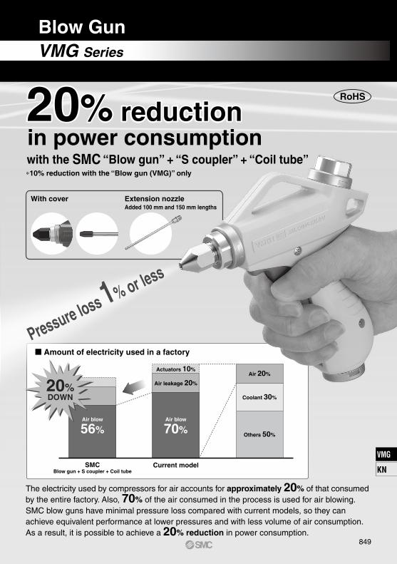
with the SMC “Blow gun” + “S coupler” + “Coil tube”
in power consumption ∗10% reduction with the “Blow gun (VMG)” only
SMC Current modelBlow gun + S coupler + Coil tube
Air 20%Actuators 10%
Air leakage 20%
Air blow
70%Air blow
56%
DOWN20%
With cover Extension nozzleAdded 100 mm and 150 mm lengths
Amount of electricity used in a factory
20% reduction20% reduction
The electricity used by compressors for air accounts for approximately 20% of that consumed by the entire factory. Also, 70% of the air consumed in the process is used for air blowing. SMC blow guns have minimal pressure loss compared with current models, so they can achieve equivalent performance at lower pressures and with less volume of air consumption. As a result, it is possible to achieve a 20% reduction in power consumption.
Pressure loss 1% or less
RoHS
VMG Series
Blow Gun
849
VMG
KN
VMG
0 0.2 0.4 0.6 0.8 1Supply pressure (MPa)
Pre
ssu
re lo
ss (
MP
a)
0
0.1
0.05
0.15
0.2
0.25
0.3
Pressure loss ···Current model
Energy Saving Pneumatic System Proposal
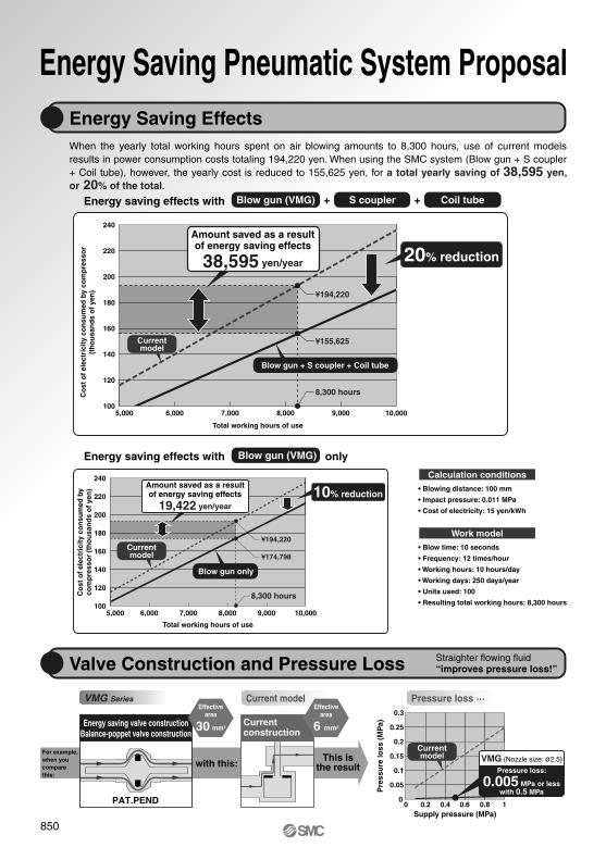
• Blowing distance: 100 mm
• Impact pressure: 0.011 MPa
• Cost of electricity: 15 yen/kWh
• Blow time: 10 seconds
• Frequency: 12 times/hour
• Working hours: 10 hours/day
• Working days: 250 days/year
• Units used: 100
• Resulting total working hours: 8,300 hours
For example,when youcomparethis:
with this:This is
the result
Current construction
Pressure loss:
0.005 MPa or lesswith 0.5 MPa
VMG (Nozzle size: ø2.5)
Effectivearea
6 mm2
Energy Saving Effects
Valve Construction and Pressure Loss
When the yearly total working hours spent on air blowing amounts to 8,300 hours, use of current models results in power consumption costs totaling 194,220 yen. When using the SMC system (Blow gun + S coupler + Coil tube), however, the yearly cost is reduced to 155,625 yen, for a total yearly saving of 38,595 yen, or 20% of the total.
240
220
200
180
160
140
120
1005,000 6,000 7,000 8,000 9,000 10,000
Total working hours of use
240
220
200
180
160
140
120
1005,000 6,000 7,000 8,000 9,000 10,000
Total working hours of use
Calculation conditions
Work model
VMG Series
Energy saving valve constructionBalance-poppet valve construction
Effectivearea
30 mm2
S coupler Coil tube+ +Energy saving effects with Blow gun (VMG)
Co
st o
f el
ectr
icit
y co
nsu
med
by
com
pre
sso
r(t
ho
usa
nd
s o
f ye
n)
Blow gun (VMG)Energy saving effects with only
Co
st o
f el
ectr
icit
y co
nsu
med
by
com
pre
sso
r (t
ho
usa
nd
s o
f ye
n)
Straighter flowing fluid“improves pressure loss!”
Currentmodel
PAT.PEND
Blow gun only
¥194,220
¥174,798
8,300 hours
¥194,220
¥155,625
8,300 hours
20% reduction
Blow gun + S coupler + Coil tube
Amount saved as a resultof energy saving effects
38,595 yen/year
Currentmodel
Amount saved as a resultof energy saving effects
19,422 yen/year
Amount saved as a resultof energy saving effects
19,422 yen/year
Currentmodel
10% reduction
850
Currentcoil tube model
SMC helps you work toward a revolutionized production system with a focus on saving-energy.
Effects of lowered pressure
Afterimprovement
Beforeimprovement
Effects of reduced flow volume
Effects of reduced power consumption
Review the air-blow job and change to the SMC blow gun, S coupler and coil tube to create a larger effec-tive area.
Currentcoupler model
Nozzle ø3Air gun
S coupler
Coil tube
Filterregulator
Nozzle ø2.5VMG
Effective arearatio
3.04 : 1
S2S0 to S1
Current coil tube model (I.D. ø5, equivalent length 5 m)
Current model
Current model (Nozzle size ø3)
5.1 mm2
6 mm2
6.3 mm2
TCU1065-1-20-X6
S coupler
VMG (Nozzle size ø2.5)
13.45 mm2
30 mm2
4.4 mm2
0.011 MPa (at a distance of 100 mm)
0.5 MPa
0.276 MPa
0.011 MPa (at a distance of 100 mm)
0.4 MPa
0.385 MPa
Coupler
Piping
Air gun
Coupler, Piping (S0)
Air gun (S1)
Nozzle (S2)
Impact pressure
Effective area ratio (S0 to S1: S2)
Compressor pressure
Air consumption
Power consumption by compressor
Regulator pressure
Pressure inside nozzle
Equipment
Effective area
Before improvementAfter improvement
0.6 MPa
287 dm3/min (ANR)
1.56 kW
0.5 MPa
257 dm3/min (ANR)
1.25 kW
0.69 : 13.04 : 1
10.4%reduction inflow volume
20%reduction
16.7%reduction in
pressure
Example of Improvement
L
1 2
L
1 2
After improvement Before improvement
S2S0 to S1
Effective arearatio
0.69 : 1
Afterimprovement
Beforeimprovement
Afterimprovement
Beforeimprovement
851
VMG
KN
VMG
For pressure loss improvement S coupler: KK Series
With a structure that employs no steel balls, the coupler achieves a slim body without narrowing of the channel, allow-ing coverage of a wide effective area.
Special method of connection and fixation
Improved fitting’s restrictor and leakage
Blow Gun, Coil Tube and S Coupler Selection
Energy Saving Flow
Related Product
Air guns with an effective area around 6 mm2 are most commonly used.But the SMC blow gun achieves a 30 mm2 effective area.
Method
Process
Effects
Features
Energy saving!
So
Thus…
Required less air consumption Effective discharge at low pressure
Reduction in the amount of electricityconsumed by compressor
Pressure drop: SmallHigh pressure right before the nozzle
Effective area: Large
As a result…
TCU0604-1-20-X6KQ2H06-02ASUp to 20 mm VMG1-02-01 KK4P-06Hø1
TCU0604-1-20-X6KQ2H06-02ASUp to 40 mm VMG1-02-02 KK4P-06Hø1.5
TCU0805-1-20-X6KQ2H08-02ASUp to 60 mm VMG1-02-03 KK4P-08Hø2
TCU1065-1-20-X6KQ2H10-02ASOver 60 mm VMG1-02-04 KK4P-10Hø2.5
DistanceNozzle size Coil tube∗FittingBlow gun
Recommended systemS coupler
∗: B (Black), W (White), R (Red), BU (Blue), Y (Yellow), G (Green), C (Clear), YR (Orange)
Recommended system in accordance with the distance
Energy saving effects are enhanced through the appropriate blow gun model selection in accordance with the distance from the target object.
By not blocking the channel with the valve spring, the loss of effective area can be minimized.
Smooth channel with minimal unevenness
The surface-to-surface design allows super-tight sealing.
Seal structure with minimal leakage
This structure achieves smooth flow through the channel.
Conical structure of check valve tip
852
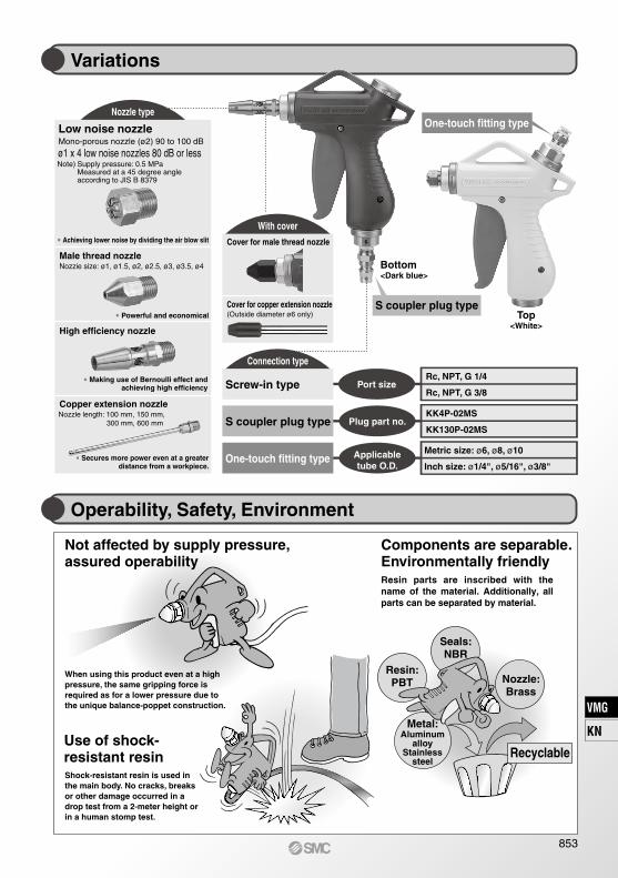
Operability, Safety, Environment
Variations
Nozzle type
With cover
Metal:Aluminum
alloyStainless
steel
When using this product even at a high pressure, the same gripping force is required as for a lower pressure due to the unique balance-poppet construction.
Resin parts are inscribed with the name of the material. Additionally, all parts can be separated by material.
Shock-resistant resin is used in the main body. No cracks, breaks or other damage occurred in a drop test from a 2-meter height or in a human stomp test.
Use of shock-resistant resin
Not affected by supply pressure,assured operability
Components are separable. Environmentally friendly
Resin:PBT
Seals:NBR
Nozzle:Brass
Recyclable
∗ Secures more power even at a greaterdistance from a workpiece.
Copper extension nozzle
∗ Achieving lower noise by dividing the air blow slit
Cover for copper extension nozzle∗ Powerful and economical
∗ Making use of Bernoulli effect andachieving high efficiency
High efficiency nozzle
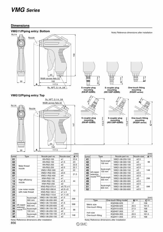
One-touch fitting type
S coupler plug typeTop
<White>
Bottom<Dark blue>
Connection type
Plug part no.
Rc, NPT, G 1/4
Rc, NPT, G 3/8
KK4P-02MS
KK130P-02MS
Applicabletube O.D.
Metric size: ø6, ø8, ø10
Inch size: ø1/4", ø5/16", ø3/8"
Screw-in type
S coupler plug type
One-touch fitting type
Port size
Low noise nozzleMono-porous nozzle (ø2) 90 to 100 dB
ø1 x 4 low noise nozzles 80 dB or lessNote) Supply pressure: 0.5 MPa Measured at a 45 degree angle according to JIS B 8379
853
VMG
KN
VMG
How to Order
VMG 1 1 02 32W C
Note) Part number for set of extension nozzle and fitting. Extension nozzle and fitting are included in the same package.Refer to “How to attach extension nozzle” in the operation manual for assembly procedures.
Body colorWhite
Dark blueWBU
Piping entryBottom
Top12
Male thread nozzle
High efficiency nozzle
Low noise nozzle with male thread
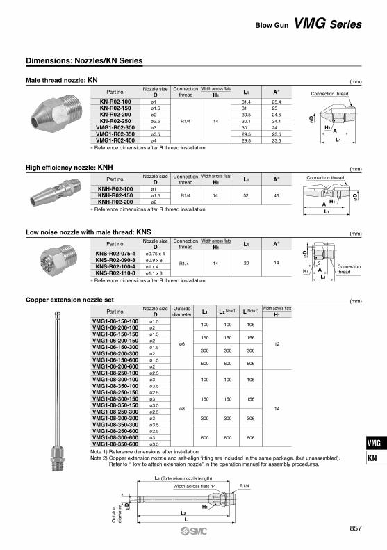
NozzleTypeSymbol Nozzle part no.
Without nozzleKN-R02-100KN-R02-150KN-R02-200KN-R02-250
Nozzle sizeø1ø1.5ø2ø2.5ø3ø3.5ø4ø1ø1.5ø2ø0.75 x 4ø0.9 x 8ø1 x 4ø1.1 x 8ø1.5ø2ø1.5ø2ø1.5ø2ø1.5ø2
01020304050607111213212223243132333435363738
A Note)
23.4 23 22.5 22.1 22
21.5
44
12
298
598
98
148
ø6 copperextensionnozzle Note)
Nozzle length:300 mm
Nozzle length:600 mm
Nozzle length:100 mm
Nozzle length:150 mm
TypeSymbol Nozzle part no.VMG1-08-250-100VMG1-08-300-100VMG1-08-350-100VMG1-08-250-150VMG1-08-300-150VMG1-08-350-150VMG1-08-250-300VMG1-08-300-300VMG1-08-350-300VMG1-08-250-600VMG1-08-300-600VMG1-08-350-600
Note 1) Reference dimensions after installationNote 2) Copper extension nozzle and self-align fitting are included in the same package, (but unassembled).
Refer to “How to attach extension nozzle” in the operation manual for assembly procedures.
Blow Gun VMG Series
857
VMG
KN
VMG
Width acrossflats 17
25
23.5
Width acrossflats 17
ø10
22
(mm)
Dimensios: Nozzle Cover
P5670129-01P5670129-01FP5670129-02P5670129-02F
HNBRFluororubber
HNBRFluororubber
VMG1--01 to 04
VMG1--05 to 07
Nozzle cover part no. MaterialApplicable blow gun modelModel
Male thread nozzleø1 to ø2.5
Male thread nozzleø3 to ø4
Nozzle type
(mm)
P5670129-11P5670129-11F
HNBRFluororubber
VMG1--31 to 38
Nozzle cover part no. MaterialApplicable blow gun modelModel
ø6 copperextension nozzle
Nozzle type
VMG1--1 to 04
VMG1--05 to 07
VMG1--31 to 38
Cover for male thread nozzle
Cover for copper extension nozzle
VMG Series
858
Nozzle tightening torque range 12 to 14 N⋅m
Nozzle holderWrench
Winding direction
Sealant tape
Expose approx. 2 threads.
Male thread
R1/4
R3/8
Tightening torque N⋅m12 to 14
22 to 24
PortWrench
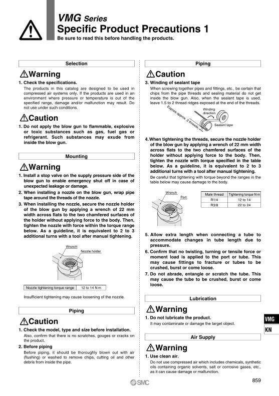
Specific Product Precautions 1Be sure to read this before handling the products.
VMG Series
Selection
Warning1. Check the specifications.
The products in this catalog are designed to be used in compressed air systems only. If the products are used in an environment where pressure or temperature is out of the specified range, damage and/or malfunction may result. Do not use under such conditions.
Mounting
Warning1. Install a stop valve on the supply pressure side of the
blow gun to enable emergency shut off in case of unexpected leakage or damage.
2. When installing a nozzle on the blow gun, wrap pipe tape around the threads of the nozzle.
3. When installing the nozzle, secure the nozzle holder of the blow gun by applying a wrench of 22 mm width across flats to the two chamfered surfaces of the holder without applying force to the body. Then, tighten the nozzle with force within the torque range below. As a guideline, it is equivalent to 2 to 3 additional turns with a tool after manual tightening.
Piping
Caution1. Check the model, type and size before installation.
Also, confirm that there is no scratches, gouges or cracks on the product.
2. Before pipingBefore piping, it should be thoroughly blown out with air (flushing) or washed to remove chips, cutting oil and other debris from inside the pipe.
Insufficient tightening may cause loosening of the nozzle.
Caution1. Do not apply the blow gun to flammable, explosive
or toxic substances such as gas, fuel gas or refrigerant. Such substances may exude from inside the blow gun.
Piping
Caution3. Winding of sealant tape
When screwing together pipes and fittings, etc., be certain that chips from the pipe threads and sealing material do not get inside the blow gun. Also, when the sealant tape is used, leave 1.5 to 2 thread ridges exposed at the end of the threads.
4. When tightening the threads, secure the nozzle holder of the blow gun by applying a wrench of 22 mm width across flats to the two chamfered surfaces of the holder without applying force to the body. Then, tighten the nozzle with torque specified in the table below. As a guideline, it is equivalent to 2 to 3 additional turns with a tool after manual tightening.Be careful that tightening with torque beyond the ranges in the table below may cause damage to the body.
5. Allow extra length when connecting a tube to accommodate changes in tube length due to pressure.
6. Confirm that no twisting, turning or tensile force or moment load is applied to the port or tube. This may cause fittings to fracture or tubes to be crushed, burst or come loose.
7. Do not abrade, entangle or scratch the tube. This may cause the tube to be crushed, burst or come loose.
Lubrication
Warning1. Do not lubricate the product.
It may contaminate or damage the target object.
Air Supply
Warning1. Use clean air.
Do not use compressed air which includes chemicals, synthetic oils containing organic solvents, salt or corrosive gases, etc., as it can cause damage or malfunction.
859
VMG
KN
VMG
Hook
Air Supply
9. When the blow gun is used or stored, confirm that no twisting, turning or tensile force or moment load is applied to the port or tube. This may cause fittings to fracture or tubes to be crushed, burst or come loose.
10. When attaching a nozzle cover, align the hex parts of the nozzle and nozzle cover before covering. When attaching an extension nozzle cover, confirm that the nozzle tip is completely inserted into the extension nozzle cover.
11. Do not use a nozzle cover or extension nozzle cover if it is cracked or does not fit securely, and replace with a new cover.
Caution1. Install air filters.
Install air filters at the upstream side of blow gun. Choose the filtration degree of 5 µm or finer.
2. Install an after-cooler, air dryer or water droplet separator, etc.Air excessive drainage may cause a malfunction of blow gun and contaminate or damage the target object. To prevent this, install an after-cooler, air dryer or water droplet separator, etc.
Operating Environment
Warning1. Do not use in an atmosphere of corrosive gases,
chemicals, sea water, water or water vapor or in an environment where such substances may adhere.
2. Provide shading in an environment where the product is exposed to the sunlight.
3. Do not use in an environment where a heat source is at a close distance.
4. Do not use in an environment where static electricity is a problem. It may cause malfunction or failure of the system. Please contact SMC for use in such an environment.
5. Do not use in an environment where spatters are generated. There is danger of fires caused by spattering. Please contact SMC for use in such an environment.
6. Do not use in an environment where the product is exposed to cutting oil, lubricating oil or coolant oil. Please contact SMC for use in an environment where the product is exposed to such liquid as cutting oil, lubricating oil or coolant oil.
Maintenance
Caution1. In periodical inspections, check the following items
and replace the parts if necessary.a) Scratches, gouges, abrasion, corrosionb) Air leakagec) Twisting, crushing and turning of connected tubesd) Hardening, deterioration and softening of connected tubese) Loosening of nozzles
2. When removing the product, first stop the pressure supply, exhaust compressed air in the piping and check the condition of atmospheric release.
3. Do not disassemble or remodel the body of the product.
Handling
Warning1. To prevent lurching of the nozzle due to air
pressure, confirm that the nozzle is not loosened or rattling by pulling it by hand before operation.
2. Make sure to wear safety goggles to protect yourself from splashed substances.
3. Do not direct the tip of the nozzle at the face or other parts of a human body. It may cause danger to personnel.
4. Do not use the product to clean or remove toxic substances or chemicals.
5. Do not drop, step on or hit the product. It may cause damage to the product.
6. Do not use the product to disturb public order or public hygiene.
7. This product is not a toy.8. After blowing, make sure to hang the product on a
hook, etc.If leaving the product in a dusty place, particles will enter the product and may result in a malfunction.
Specific Product Precautions 2Be sure to read this before handling the products.