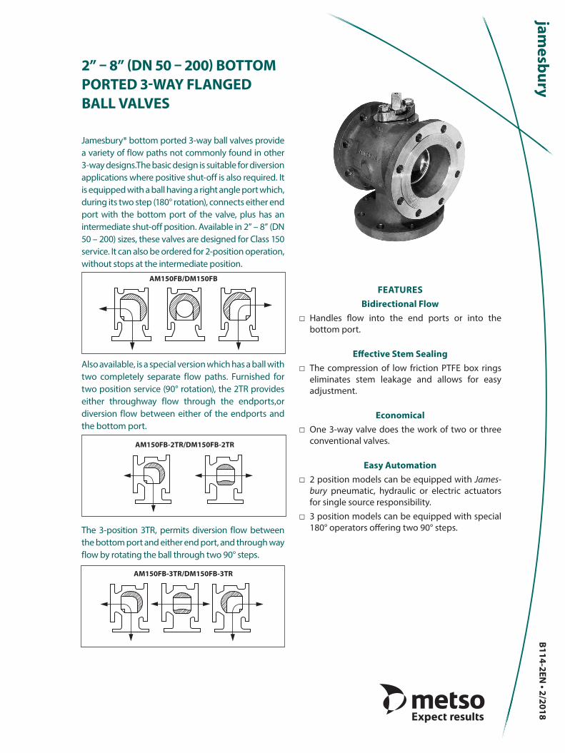
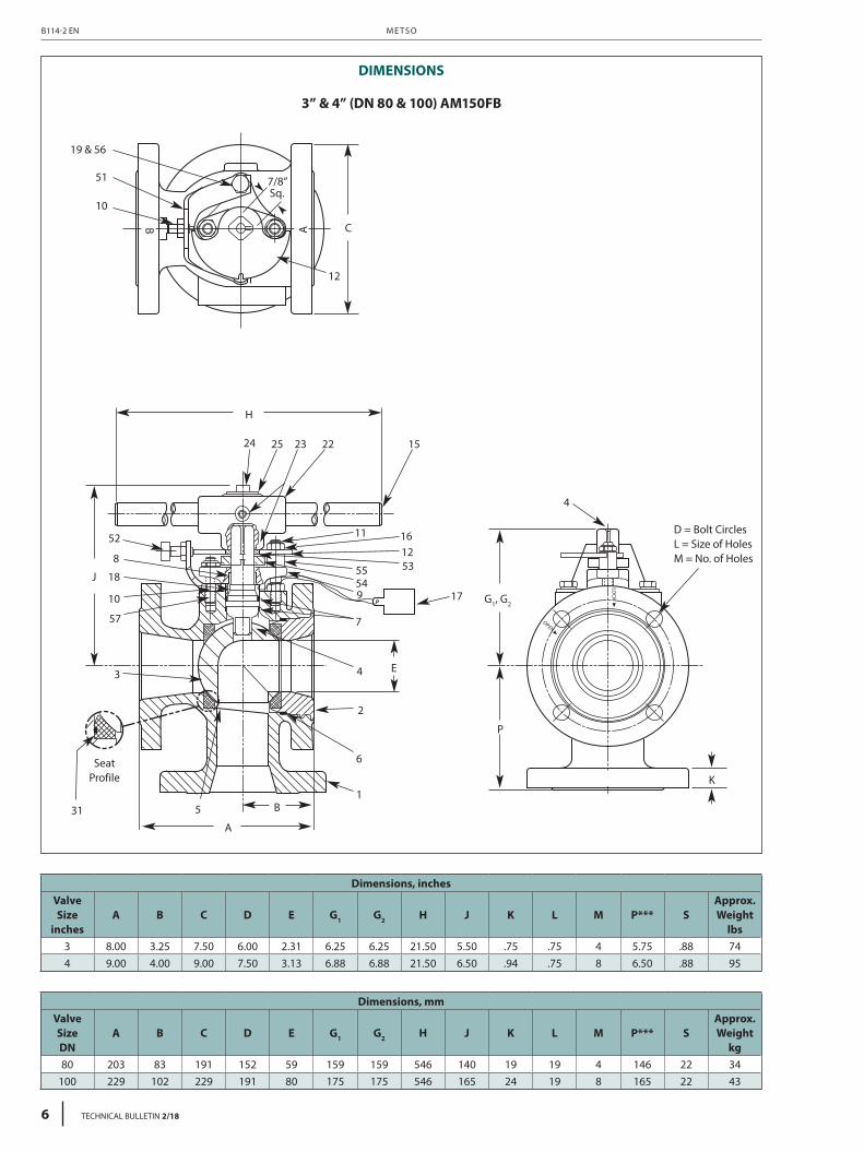
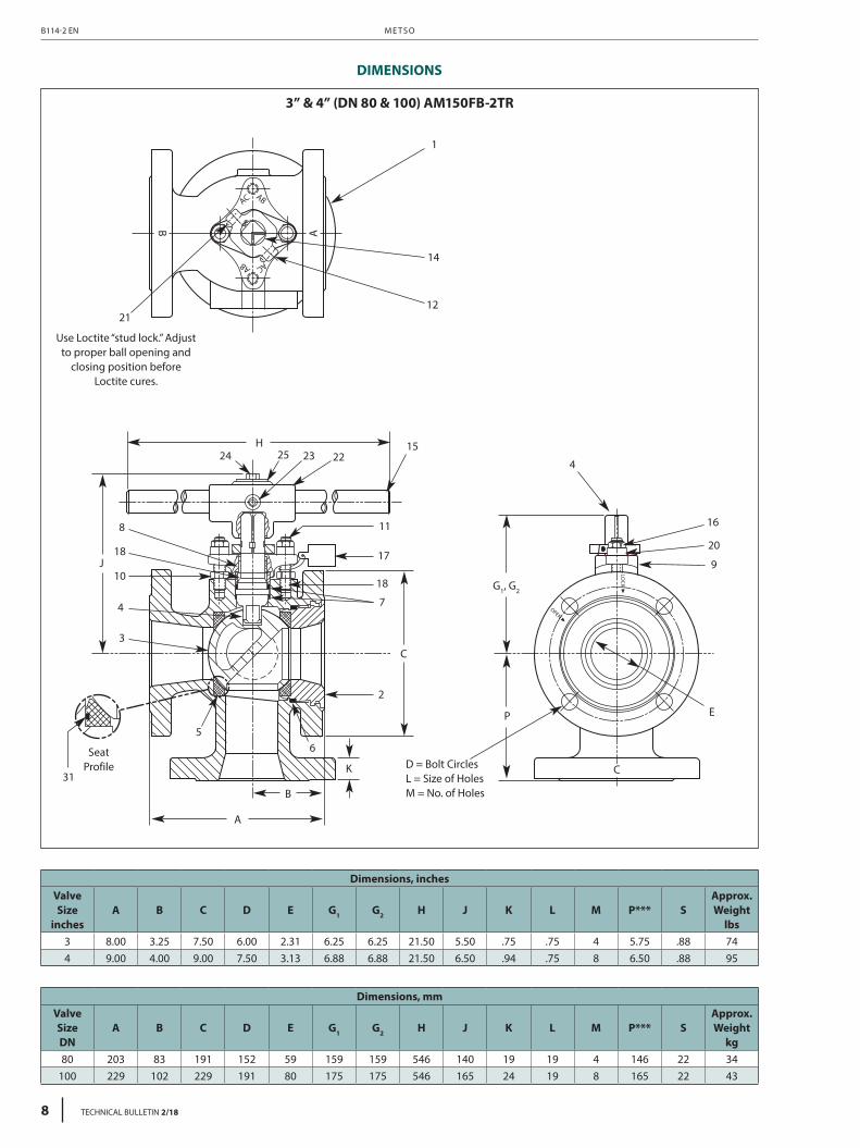
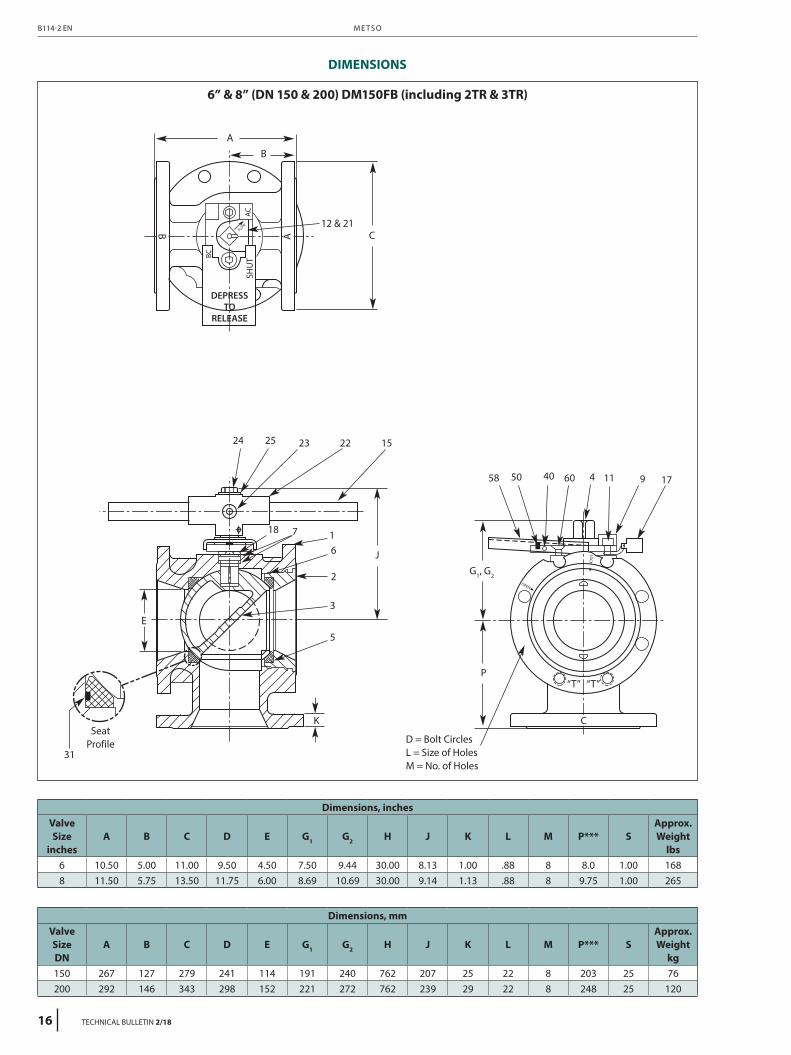
2” – 8” (DN 50 – 200) BOTTOM PORTED 3-WAY FLANGED BALL VALVES Jamesbury® bottom ported 3-way ball valves provide a variety of flow paths not commonly found in other 3-way designs.The basic design is suitable for diversion applications where positive shut-off is also required. It is equipped with a ball having a right angle port which, during its two step (180° rotation), connects either end port with the bottom port of the valve, plus has an intermediate shut-off position. Available in 2” – 8” (DN 50 – 200) sizes, these valves are designed for Class 150 service. It can also be ordered for 2-position operation, without stops at the intermediate position. Also available, is a special version which has a ball with two completely separate flow paths. Furnished for two position service (90° rotation), the 2TR provides either throughway flow through the endports,or diversion flow between either of the endports and the bottom port. The 3-position 3TR, permits diversion flow between the bottom port and either end port, and through way flow by rotating the ball through two 90° steps. FEATURES Bidirectional Flow □ Handles flow into the end ports or into the bottom port. Effective Stem Sealing □ The compression of low friction PTFE box rings eliminates stem leakage and allows for easy adjustment. Economical □ One 3-way valve does the work of two or three conventional valves. Easy Automation □ 2 position models can be equipped with James- bury pneumatic, hydraulic or electric actuators for single source responsibility. □ 3 position models can be equipped with special 180° operators offering two 90° steps. AM150FB-3TR/DM150FB-3TR AM150FB/DM150FB AM150FB-2TR/DM150FB-2TR B114-2EN • 2/2018
Jamesbury® bottom ported 3-way ball valves provide a variety of flow paths not commonly found in other 3-way designs.The basic design is suitable for diversion applications where positive shut-off is also required. It is equipped with a ball having a right angle port which, during its two step (180° rotation), connects either end port with the bottom port of the valve, plus has an intermediate shut-off position. Available in 2” – 8” (DN 50 – 200) sizes, these valves are designed for Class 150 service. It can also be ordered for 2-position operation, without stops at the intermediate position.
Also available, is a special version which has a ball with two completely separate flow paths. Furnished for two position service (90° rotation), the 2TR provides either throughway flow through the endports,or diversion flow between either of the endports and the bottom port.
The 3-position 3TR, permits diversion flow between the bottom port and either end port, and through way flow by rotating the ball through two 90° steps.
FEATURESBidirectional Flow
□ Handles flow into the end ports or into the bottom port.
Effective Stem Sealing □ The compression of low friction PTFE box rings
eliminates stem leakage and allows for easy adjustment.
Economical □ One 3-way valve does the work of two or three
conventional valves.
Easy Automation □ 2 position models can be equipped with James-
bury pneumatic, hydraulic or electric actuators for single source responsibility.
□ 3 position models can be equipped with special 180° operators offering two 90° steps.
AM150FB-3TR/DM150FB-3TR
AM150FB/DM150FB
AM150FB-2TR/DM150FB-2TR
B114-2EN • 2/2018
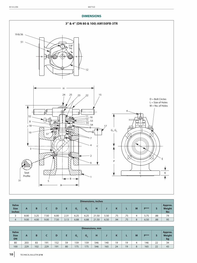
SPECIFICATIONS
VALVE SEAT RATINGS
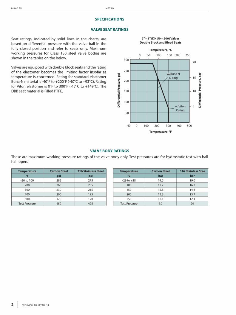
Seat ratings, indicated by solid lines in the charts, are based on differential pressure with the valve ball in the fully closed position and refer to seats only. Maximum working pressures for Class 150 steel valve bodies are shown in the tables on the below.
Valves are equipped with double block seats and the rating of the elastomer becomes the limiting factor insofar as temperature is concerned. Rating for standard elastomer Buna-N material is -40°F to +200°F (-40°C to +93°C). Rating for Viton elastomer is 0°F to 300°F (-17°C to +149°C). The DBB seat material is Filled PTFE.
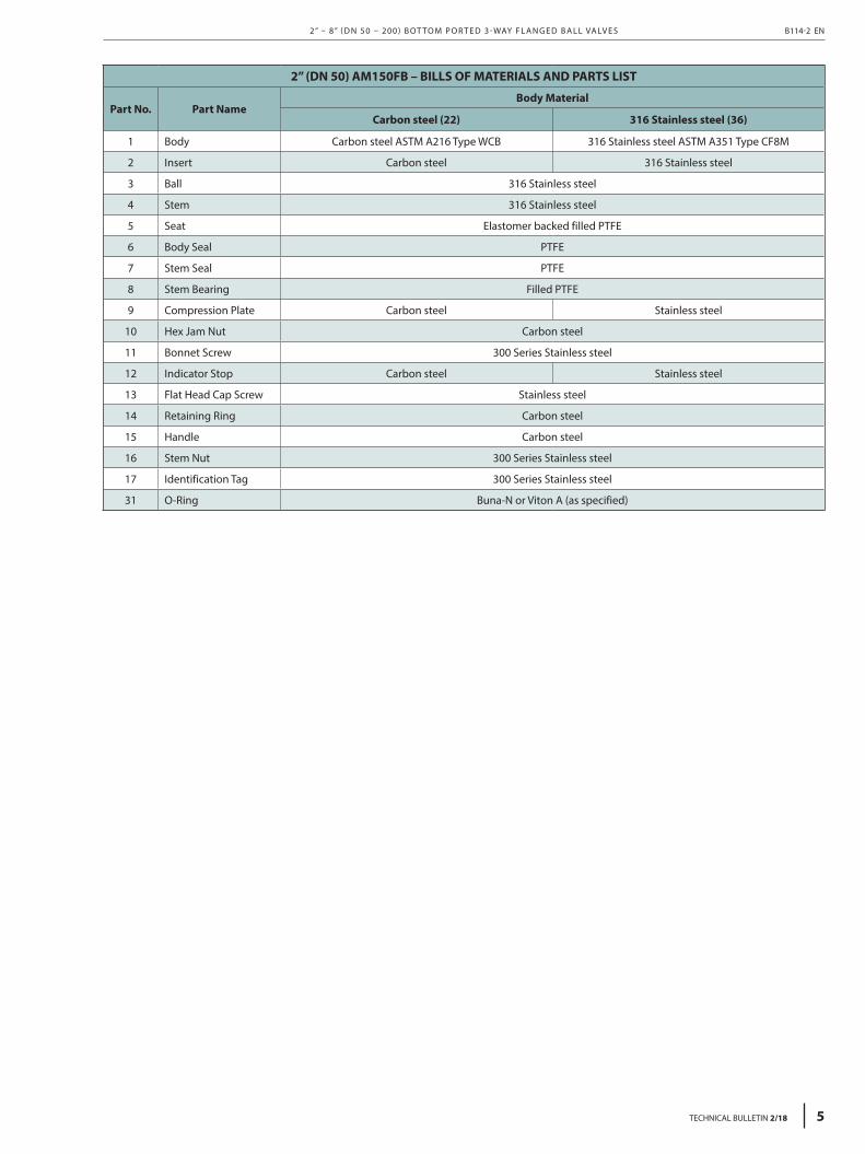
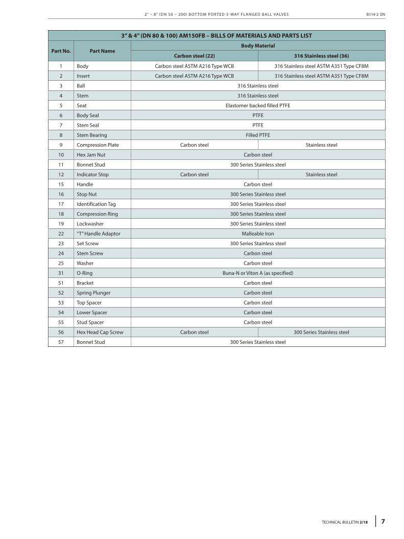
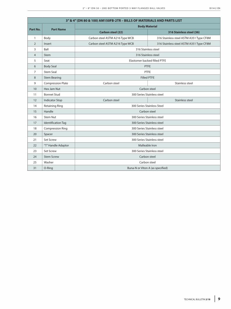
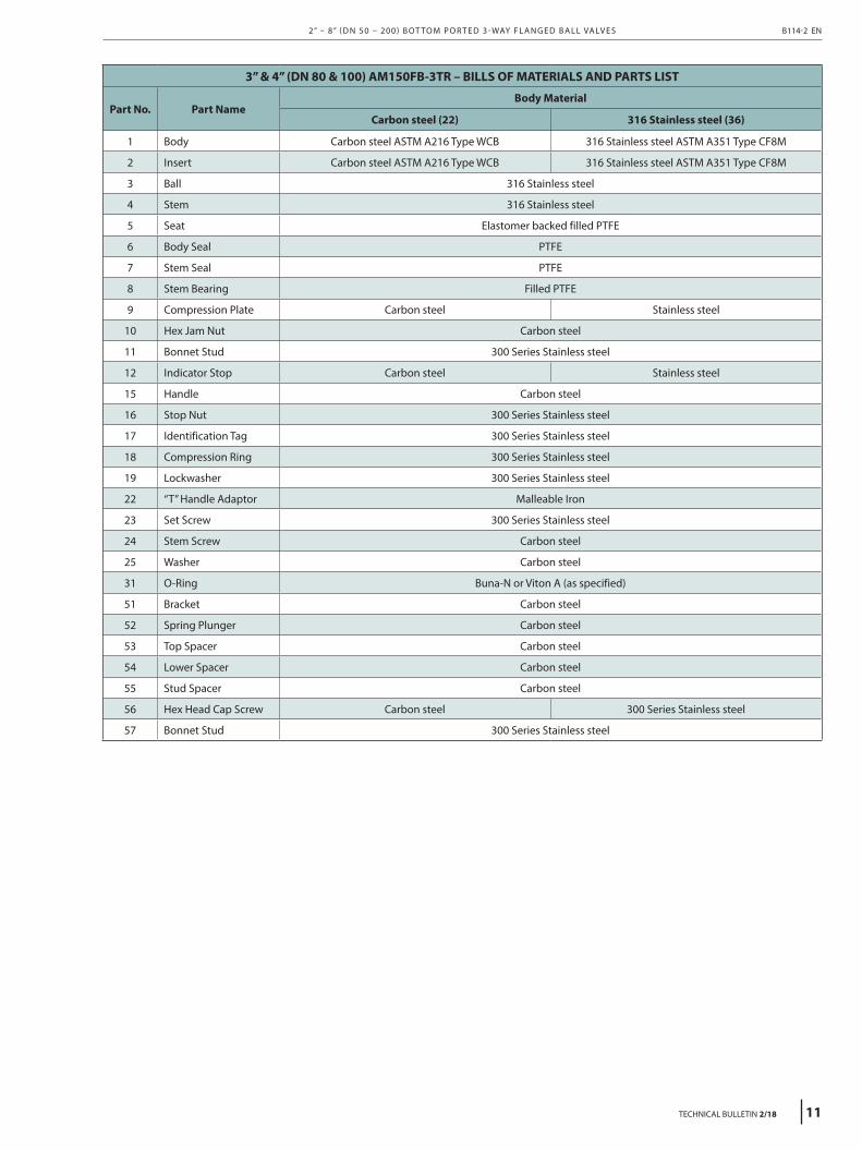
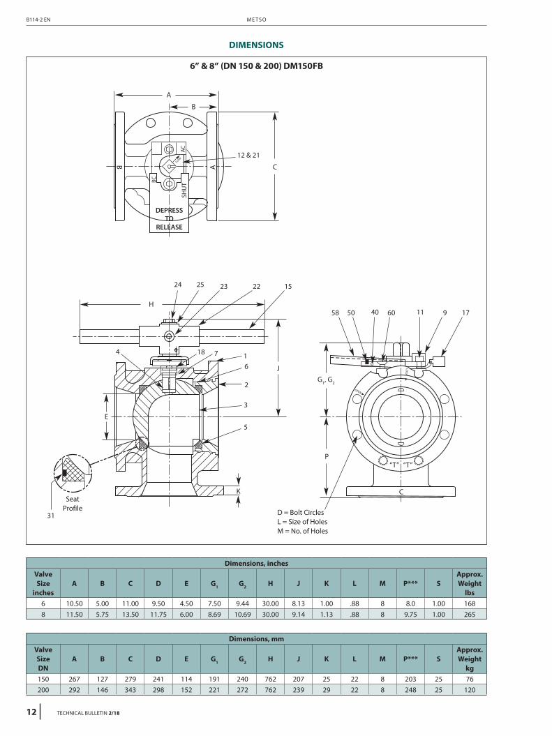
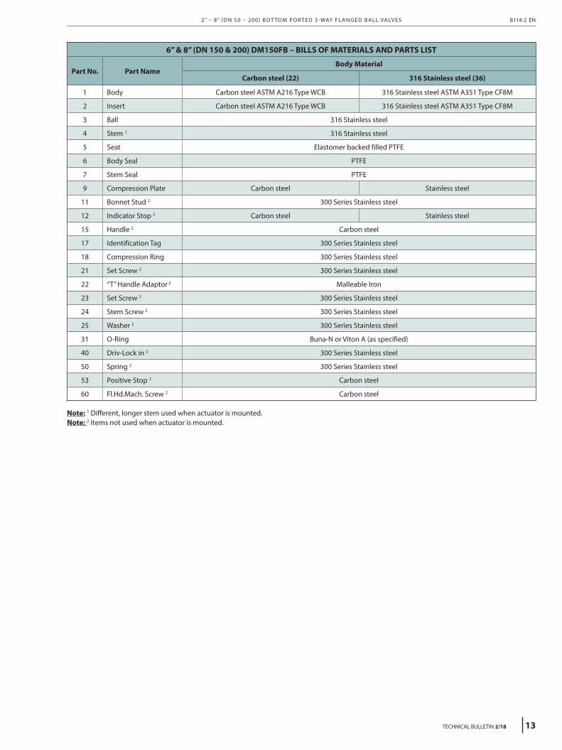
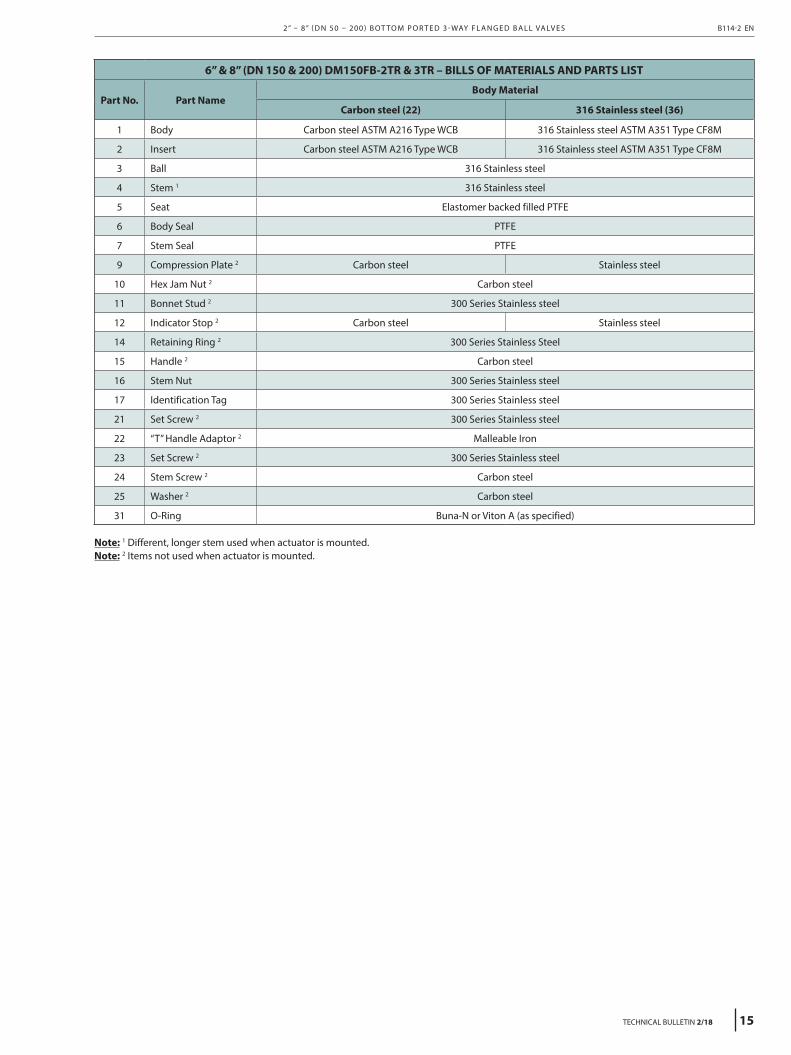
6” & 8” (DN 150 & 200) DM150FB – BILLS OF MATERIALS AND PARTS LIST
Part No. Part NameBody Material
Carbon steel (22) 316 Stainless steel (36)
1 Body Carbon steel ASTM A216 Type WCB 316 Stainless steel ASTM A351 Type CF8M
2 Insert Carbon steel ASTM A216 Type WCB 316 Stainless steel ASTM A351 Type CF8M
3 Ball 316 Stainless steel
4 Stem 1 316 Stainless steel
5 Seat Elastomer backed filled PTFE
6 Body Seal PTFE
7 Stem Seal PTFE
9 Compression Plate Carbon steel Stainless steel
11 Bonnet Stud 2 300 Series Stainless steel
12 Indicator Stop 2 Carbon steel Stainless steel
15 Handle 2 Carbon steel
17 Identification Tag 300 Series Stainless steel
18 Compression Ring 300 Series Stainless steel
21 Set Screw 2 300 Series Stainless steel
22 “T” Handle Adaptor 2 Malleable Iron
23 Set Screw 2 300 Series Stainless steel
24 Stem Screw 2 Carbon steel
25 Washer 2 Carbon steel
31 O-Ring Buna-N or Viton A (as specified)
40 Driv-Lock in 2 300 Series Stainless steel
50 Spring 2 300 Series Stainless steel
53 Positive Stop 2 Carbon steel
60 Fl.Hd.Mach. Screw 2 300 Series Stainless steel
Note: 1 Different, longer stem used when actuator is mounted.Note: 2 Items not used when actuator is mounted.
2” – 8” ( D N 50 – 200 ) B OT TO M P O R T E D 3 - WAY F L A N G E D B A L L VA LV E S B114-2 EN
TECHNICAL BULLETIN 2/18 17
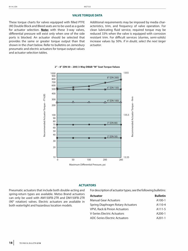
VALVE TORQUE DATA
These torque charts for valves equipped with filled PTFE (M) Double Block and Bleed seats are to be used as a guide for actuator selection. Note: with these 3-way valves, differential pressure will exist only when one of the side ports is blocked. An actuator should be selected that provides the same or greater torque output than that shown in the chart below. Refer to bulletins on Jamesbury pneumatic and electric actuators for torque output values and actuator selection tables.
Additional requirements may be imposed by media char-acteristics, trim, and frequency of valve operation. For clean lubricating fluid service, required torque may be reduced 33% when the valve is equipped with corrosion resistant trim. For difficult services (slurries, semi-solids) increase values by 50%. If in doubt, select the next larger actuator.
Pneumatic actuators that include both double-acting and spring-return types are available. Metso Brand actuators can only be used with AM150FB-2TR and DM150FB-2TR (90° rotation) valves. Electric actuators are available in both watertight and hazardous location models.
For description of actuator types, see the following bulletins:
Actuator BulletinManual Gear Actuators A100-1Spring Diaphragm Rotary Actuators A110-4VPVL Rack & Pinion Actuators A111-5V-Series Electric Actuators A200-1ADC-Series Electric Actuators A201-1
6” thru 8”AO Buna N with operating stemDO Viton with operating stem
1 Not available with 2TR/3TR ball
WARNING:As the use of the valve is application specific, a number of factors should be taken into account when selecting a valve for a given application. Therefore, some of the situations in which the valves are used are outside the scope of this manual. If you have any questions concerning the use, application or compatibility of the valve with the intended service, contact Metso for more information.
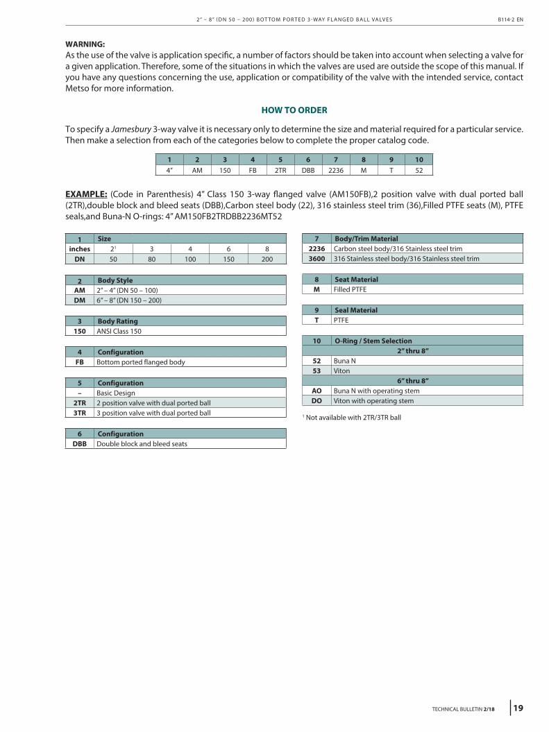
HOW TO ORDER
To specify a Jamesbury 3-way valve it is necessary only to determine the size and material required for a particular service. Then make a selection from each of the categories below to complete the proper catalog code.
1 2 3 4 5 6 7 8 9 104” AM 150 FB 2TR DBB 2236 M T 52
EXAMPLE: (Code in Parenthesis) 4” Class 150 3-way flanged valve (AM150FB),2 position valve with dual ported ball (2TR),double block and bleed seats (DBB),Carbon steel body (22), 316 stainless steel trim (36),Filled PTFE seats (M), PTFE seals,and Buna-N O-rings: 4” AM150FB2TRDBB2236MT52
2” – 8” ( D N 50 – 200 ) B OT TO M P O R T E D 3 - WAY F L A N G E D B A L L VA LV E S B114-2 EN