Direct Vent Service Manual RHFE-551FA RHFE-1001FA RHFE-1001FA/VA RHFE-201FA RHFE-263FA, FAII RHFE-431FA, FAII, FAIII, WTA RHFE-556FA, FAII, FAIII, FTRA, FTRAIII, WTA RHFE-1004FA This document, 200000014 (11/3/2008), supersedes and replaces the Direct Vent Service Manual, TDM-DV-2004.
Transcript
Direct Vent Service Manual
RHFE-551FA
RHFE-1001FA
RHFE-1001FA/VA
RHFE-201FA
RHFE-263FA, FAII
RHFE-431FA, FAII, FAIII, WTA
RHFE-556FA, FAII, FAIII, FTRA, FTRAIII, WTA
RHFE-1004FA
This document, 200000014 (11/3/2008), supersedes and replaces the Direct Vent Service Manual, TDM-DV-2004.
2 Rinnai Direct Vent Service Manual
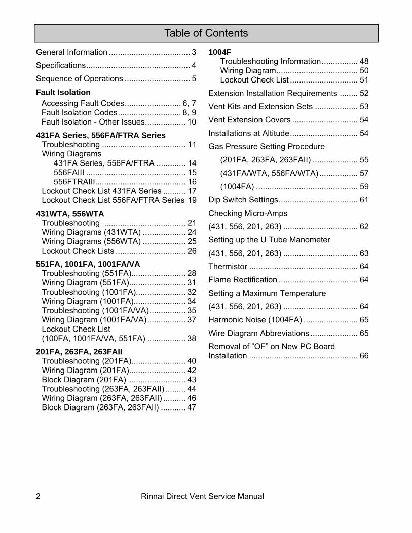
Table of Contents
General Information .................................... 3 Specifications .............................................. 4 Sequence of Operations ............................. 5
1004F Troubleshooting Information ................ 48 Wiring Diagram .................................... 50 Lockout Check List .............................. 51 Extension Installation Requirements ........ 52 Vent Kits and Extension Sets ................... 53 Vent Extension Covers ............................. 54 Installations at Altitude .............................. 54 Gas Pressure Setting Procedure (201FA, 263FA, 263FAII) .................... 55 (431FA/WTA, 556FA/WTA) ................. 57 (1004FA) ............................................. 59 Dip Switch Settings ................................... 61 Checking Micro-Amps (431, 556, 201, 263) ................................. 62 Setting up the U Tube Manometer (431, 556, 201, 263) ................................. 63 Thermistor ................................................ 64 Flame Rectification ................................... 64 Setting a Maximum Temperature (431, 556, 201, 263) ................................. 64 Harmonic Noise (1004FA) ........................ 65 Wire Diagram Abbreviations ..................... 65 Removal of “OF” on New PC Board Installation ................................................ 66
Rinnai Direct Vent Service Manual 3
General Information
Safety Definitions This is the safety alert symbol. This symbol alerts you to potential hazards that can kill or hurt you and others.
Indicates an imminently hazardous situation which, if not avoided, will result in death or serious injury.
Indicates a potentially hazardous situation which, if not avoided, could result in death or serious injury.
Indicates a potentially hazardous situation which, if not avoided, could result in minor or moderate injury. It may also be used to alert against unsafe practices.
DANGER
CAUTION
WARNING
Recommended Tools • Volt/Ohm/Amp meter with test probes
• U tube type manometer with 14 inch water column (W.C.) scale, two hoses and two 1/8 inch taps
• assorted wrenches including a 3/16 Allen wrench
• assorted screw drivers
• leak solution or leak detector
Using this Manual Repairs should be performed by a qualified service technician.
The following information can be referenced for additional information.
• Operation and Installation Manual
• Conversion Manual
• Technical Bulletins
Technical Support Technicians are available to assist in servicing issues. Contact Rinnai Technical Services at 1-800-621-9419.
WARNING There are a number of live tests that are required when fault finding this product. Extreme care should be used at all times to avoid contact with energized components inside the furnace. Before checking for resistance readings disconnect the power source to the unit and isolate the item from the circuit (unplug it).
If any of the original wire as supplied with the appliance must be replaced, it must be replaced with type 18 AWG wire or its equivalent.
Label all wires prior to disconnection when servicing controls. Wiring errors can cause improper and dangerous operation.
CAUTION
4 Rinnai Direct Vent Service Manual
Specifications
20
1FA
26
3FA
, FA
II 43
1FA
Ser
ies,
W
TA
556F
A/F
TRA
Se
ries,
WTA
10
04FA
55
1FA
10
01FA
10
01FA
/VA
BTU
Inpu
t NG
3,
000-
8,00
0 5,
500-
11,0
00
8,20
0-16
,700
8,
200-
21,5
00
10,5
00-3
8,40
0 22
,000
(max
) 38
,400
(max
)
BTU
Inpu
t LP
3,00
0-8,
000
5,70
0-11
,000
8,
200-
16,7
00
8,20
0-20
,700
10
,500
-36,
500
21,0
00 (m
ax)
36,5
00 (m
ax)
AFU
E R
atin
g N
atur
al G
as:
80.6
%
Pro
pane
Gas
: 83
.4%
Nat
ural
Gas
: 80
%
Pro
pane
Gas
: 80
%
Nat
ural
Gas
: 80
.8%
P
ropa
ne G
as:
81%
Nat
ural
Gas
: 80
.6%
P
ropa
ne G
as:
81%
Nat
ural
Gas
: 80
.6%
P
ropa
ne G
as:
82%
NA
N
A
Gas
Sup
ply
Pres
sure
(NG
) 4.
5-10
.5 in
(1
14-2
67 m
m)
W.C
.
3.5-
10.5
in
(89-
267
mm
) W
.C.
3.5-
10.5
in
(89-
267
mm
) W
.C.
5.0-
10.5
in (1
27-
267
mm
) W.C
. 5.
0-10
.5 in
(127
-26
7 m
m) W
.C.
4.5-
10.5
in (1
14-
267
mm
) W.C
. 5.
0-10
.5 in
(127
-267
mm
) W.C
.
Gas
Sup
ply
Pres
sure
(LP)
8-
13 in
(2
03-3
30 m
m)
W.C
.
8-13
in
(203
-330
mm
) W
.C.
8-13
in
(203
-330
mm
) W
.C.
8-13
in
(203
-330
mm
) W
.C.
11-1
3 in
(2
79-3
30 m
m)
W.C
.
11-1
3 in
(2
79-3
30 m
m)
W.C
.
11-1
3 in
(2
79-3
30 m
m)
W.C
.
Elec
tric
al
Con
nect
ion
(at h
igh
fire)
AC
120
V,
60 H
z,
42 w
atts
AC
120
V,
60 H
z,
47 w
atts
AC
120
V,
60 H
z,
40 w
atts
AC
120
V,
60 H
z,
55 w
atts
AC
120
V,
60 H
z,
121
wat
ts
AC
120
V,
60 H
z,
120
wat
ts
AC
120
V,
60 H
z,
120
wat
ts
Soun
d Le
vel
27-3
4 dB
(A)
31-3
8 dB
(A)
32-3
8 dB
(A)
32-4
1 dB
(A)
37-4
7 dB
(A)
35-4
4 dB
(A)
35-4
6 dB
(A)
Fan
CFM
48
.3-7
8.6
96.4
-128
.5
110.
5-14
1.3
110.
5-16
2.7
203.
4-36
0.6
135-
189
179-
289
Wei
ght
39.4
lbs
(1
7.9
kg)
37 lb
s (1
7 kg
) 51
lbs
(23
kg)
51 lb
s (2
3 kg
) 90
lbs
(41
kg)
74 (3
4 kg
) 11
0 (5
0 kg
)
Rinnai Direct Vent Service Manual 5
Sequence of Operations
1. The blower (combustion) motor fan starts and purges the combustion and heat exchanger chambers making sure that they are clear. The green LED light is on.
2. The blower stages down and the ignition module powers the spark igniter and spark occurs. When the spark is sensed as being correct, the PCB allows voltage to the solenoid gas valves and gas enters the chamber. Ignition occurs and the flame rod begins to prove flame. The blower motor stages back up to high. When the burner is on the LED glows red indicating the burner is on. If the flame is correct and a secure ground is available, then the flame rod produces micro-amps and the unit will fire trying to reach your set room temperature.
3. The convection (room blower) will start on low speed circulating warm air into the structure. After the PCB compares the set temperature to the room temperature, the seven stage gas valve and fan control will fire the unit at the most efficient rate to obtain the comfort level as set.
4. The negative co-efficient thermistor will sense the room temperature at the floor level and will provide feedback to the PCB to determine the firing rate, fan speed, and run time. When the set temperature is reached, the red indicator will return to green indicating the burner is off. The convection fan will continue to run cooling the exchangers and electronics for about 4 minutes.
5. The LED will be green indicating the unit is on standby. When the structure temperature drops, the process starts over again.
6. Fresh air for combustion is drawn from outside and exhaust air is eliminated to the outside. Moisture coming from the vent outside is normal as most high efficient units produce moisture.
6 Rinnai Direct Vent Service Manual
Fault Isolation If there is a malfunction the appliance may shut down as a safety precaution and display a fault code to assist in diagnosing the problem. The fault code will flash in the display on the control panel.
Fault codes should be used to assist in identifying the cause of the failure.
After the problem has been corrected, the fault code will clear only after the appliance has been turned off and back on. The code will be stored into the memory.
Some faults may cause a hard lockout where the appliance shuts off and corrective action is required before the appliance will operate.
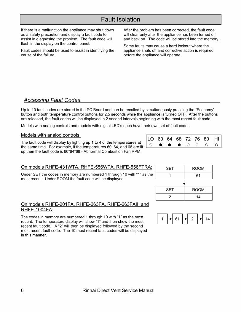
Accessing Fault Codes
Up to 10 fault codes are stored in the PC Board and can be recalled by simultaneously pressing the “Economy” button and both temperature control buttons for 2.5 seconds while the appliance is turned OFF. After the buttons are released, the fault codes will be displayed in 2 second intervals beginning with the most recent fault code.
Models with analog controls and models with digital LED’s each have their own set of fault codes.
On models RHFE-431WTA, RHFE-556WTA, RHFE-556FTRA: Under SET the codes in memory are numbered 1 through 10 with “1” as the most recent. Under ROOM the fault code will be displayed.
Models with analog controls: The fault code will display by lighting up 1 to 4 of the temperatures at the same time. For example, if the temperatures 60, 64, and 68 are lit up then the fault code is 60*64*68 - Abnormal Combustion Fan RPM.
On models RHFE-201FA, RHFE-263FA, RHFE-263FAII, and RHFE-1004FA: The codes in memory are numbered 1 through 10 with “1” as the most recent. The temperature display will show “1” and then show the most recent fault code. A “2” will then be displayed followed by the second most recent fault code. The 10 most recent fault codes will be displayed in this manner.
SET ROOM
1 61
SET ROOM
2 14
1 61 2 14
LO 60 64 68 72 76 80 HI
Rinnai Direct Vent Service Manual 7
RHFE-431WTA, RHFE-556WTA
5082 combustion hours
18420 combustion cycles (multiply displayed number by 10)
125 power failures
Accessing Operation History
RHFE-431FA, RHFE-556FA After the fault codes, the heater will display the combustion hours and combustion cycles (number of times the unit is turned on and off). The combustion time will display first in two parts followed by the combustion cycles displayed in two parts. Combustion Time 1. The temperature display will indicate a 16 digit binary number. A light indicates a “1”. A position not lighted,
indicates a “0”. Read this number using the example below.
LO 60 64 68 72 76 80 HI
LO 60 64 68 72 76 80 HI
LO 60 64 68 72 76 80 HI
LO 60 64 68 72 76 80 HI
This indicates the first 8 digits as follows: 0 1 0 0 0 0 0 1
This indicates the next 8 digits as follows: 1 1 0 1 0 0 0 0
2. Use a calculator with binary and decimal functions. Set the calculator to binary, “BIN”, and enter the 16 digits. (0 1 0 0 0 0 0 1 1 1 0 1 0 0 0 0 in the example above.)
3. Press the decimal function, “DEC”, and the combustion time in hours will display. The combustion hours in this example is 16848.
Combustion Cycles 1. The temperature display will indicate a 16 digit binary number. A light indicates a “1”. A position not lighted,
indicates a “0”. Read this number using the example below.
This indicates the first 8 digits as follows: 1 1 0 0 1 0 0 0
This indicates the next 8 digits as follows: 0 0 1 1 0 0 0 1
2. Use a calculator with binary and decimal functions. Set the calculator to binary, “BIN”, and enter the 16 digits. (1 1 0 0 1 0 0 0 0 0 1 1 0 0 0 1 in the example above.)
3. Press the decimal function, “DEC”, and multiply the displayed number by 10 to obtain the combustion cycles. The combustion cycles in this example is 512,490.
50 82
18 42
1 25
SET ROOM
50 82
18 42
1 25
After the fault codes, the heater will display the combustion hours, combustion cycles (number of times the unit is turned on and off), and power failure frequency.
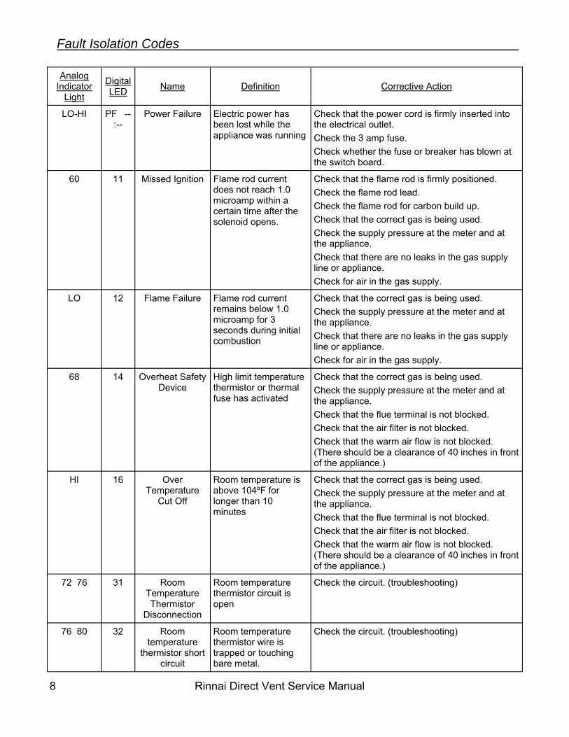
Power Failure Electric power has been lost while the appliance was running
Check that the power cord is firmly inserted into the electrical outlet. Check the 3 amp fuse. Check whether the fuse or breaker has blown at the switch board.
60 11 Missed Ignition Flame rod current does not reach 1.0 microamp within a certain time after the solenoid opens.
Check that the flame rod is firmly positioned. Check the flame rod lead. Check the flame rod for carbon build up. Check that the correct gas is being used. Check the supply pressure at the meter and at the appliance. Check that there are no leaks in the gas supply line or appliance. Check for air in the gas supply.
LO 12 Flame Failure Flame rod current remains below 1.0 microamp for 3 seconds during initial combustion
Check that the correct gas is being used. Check the supply pressure at the meter and at the appliance. Check that there are no leaks in the gas supply line or appliance. Check for air in the gas supply.
68 14 Overheat Safety Device
High limit temperature thermistor or thermal fuse has activated
Check that the correct gas is being used. Check the supply pressure at the meter and at the appliance. Check that the flue terminal is not blocked. Check that the air filter is not blocked. Check that the warm air flow is not blocked. (There should be a clearance of 40 inches in front of the appliance.)
HI 16 Over Temperature
Cut Off
Room temperature is above 104ºF for longer than 10 minutes
Check that the correct gas is being used. Check the supply pressure at the meter and at the appliance. Check that the flue terminal is not blocked. Check that the air filter is not blocked. Check that the warm air flow is not blocked. (There should be a clearance of 40 inches in front of the appliance.)
72 76 31 Room Temperature Thermistor
Disconnection
Room temperature thermistor circuit is open
Check the circuit. (troubleshooting)
76 80 32 Room temperature
thermistor short circuit
Room temperature thermistor wire is trapped or touching bare metal.
Check the circuit. (troubleshooting)
Fault Isolation Codes
Rinnai Direct Vent Service Manual 9
Analog Indicator
Light
Digital LED Name Definition Corrective Action
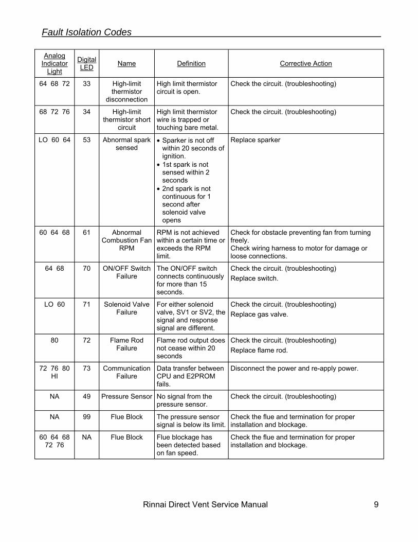
64 68 72 33 High-limit thermistor
disconnection
High limit thermistor circuit is open.
Check the circuit. (troubleshooting)
68 72 76 34 High-limit thermistor short
circuit
High limit thermistor wire is trapped or touching bare metal.
Check the circuit. (troubleshooting)
LO 60 64 53 Abnormal spark sensed
• Sparker is not off within 20 seconds of ignition.
• 1st spark is not sensed within 2 seconds
• 2nd spark is not continuous for 1 second after solenoid valve opens
Replace sparker
60 64 68 61 Abnormal Combustion Fan
RPM
RPM is not achieved within a certain time or exceeds the RPM limit.
Check for obstacle preventing fan from turning freely. Check wiring harness to motor for damage or loose connections.
64 68 70 ON/OFF Switch Failure
The ON/OFF switch connects continuously for more than 15 seconds.
Check the circuit. (troubleshooting) Replace switch.
LO 60 71 Solenoid Valve Failure
For either solenoid valve, SV1 or SV2, the signal and response signal are different.
Check the circuit. (troubleshooting) Replace gas valve.
80 72 Flame Rod Failure
Flame rod output does not cease within 20 seconds
Check the circuit. (troubleshooting) Replace flame rod.
72 76 80 HI
73 Communication Failure
Data transfer between CPU and E2PROM fails.
Disconnect the power and re-apply power.
NA 49 Pressure Sensor No signal from the pressure sensor.
Check the circuit. (troubleshooting)
NA 99 Flue Block The pressure sensor signal is below its limit.
Check the flue and termination for proper installation and blockage.
60 64 68 72 76
NA Flue Block Flue blockage has been detected based on fan speed.
Check the flue and termination for proper installation and blockage.
Fault Isolation Codes
10 Rinnai Direct Vent Service Manual
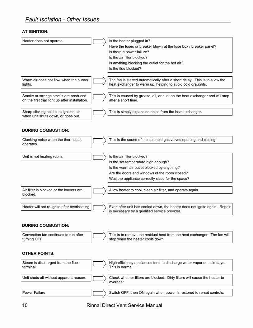
Heater does not operate. Is the heater plugged in? Have the fuses or breaker blown at the fuse box / breaker panel? Is there a power failure? Is the air filter blocked? Is anything blocking the outlet for the hot air? Is the flue blocked?
AT IGNITION:
Warm air does not flow when the burner lights.
The fan is started automatically after a short delay. This is to allow the heat exchanger to warm up, helping to avoid cold draughts.
Smoke or strange smells are produced on the first trial light up after installation.
This is caused by grease, oil, or dust on the heat exchanger and will stop after a short time.
Sharp clicking noised at ignition, or when unit shuts down, or goes out.
This is simply expansion noise from the heat exchanger.
DURING COMBUSTION:
Clunking noise when the thermostat operates.
This is the sound of the solenoid gas valves opening and closing.
Unit is not heating room. Is the air filter blocked? Is the set temperature high enough? Is the warm air outlet blocked by anything? Are the doors and windows of the room closed? Was the appliance correctly sized for the space?
Air filter is blocked or the louvers are blocked.
Allow heater to cool, clean air filter, and operate again.
Heater will not re-ignite after overheating Even after unit has cooled down, the heater does not ignite again. Repair is necessary by a qualified service provider.
DURING COMBUSTION:
Convection fan continues to run after turning OFF
This is to remove the residual heat from the heat exchanger. The fan will stop when the heater cools down.
OTHER POINTS:
Steam is discharged from the flue terminal.
High efficiency appliances tend to discharge water vapor on cold days. This is normal.
Unit shuts off without apparent reason. Check whether filters are blocked. Dirty filters will cause the heater to overheat.
Power Failure Switch OFF, then ON again when power is restored to re-set controls.
Fault Isolation - Other Issues
Rinnai Direct Vent Service Manual 11
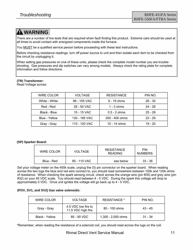
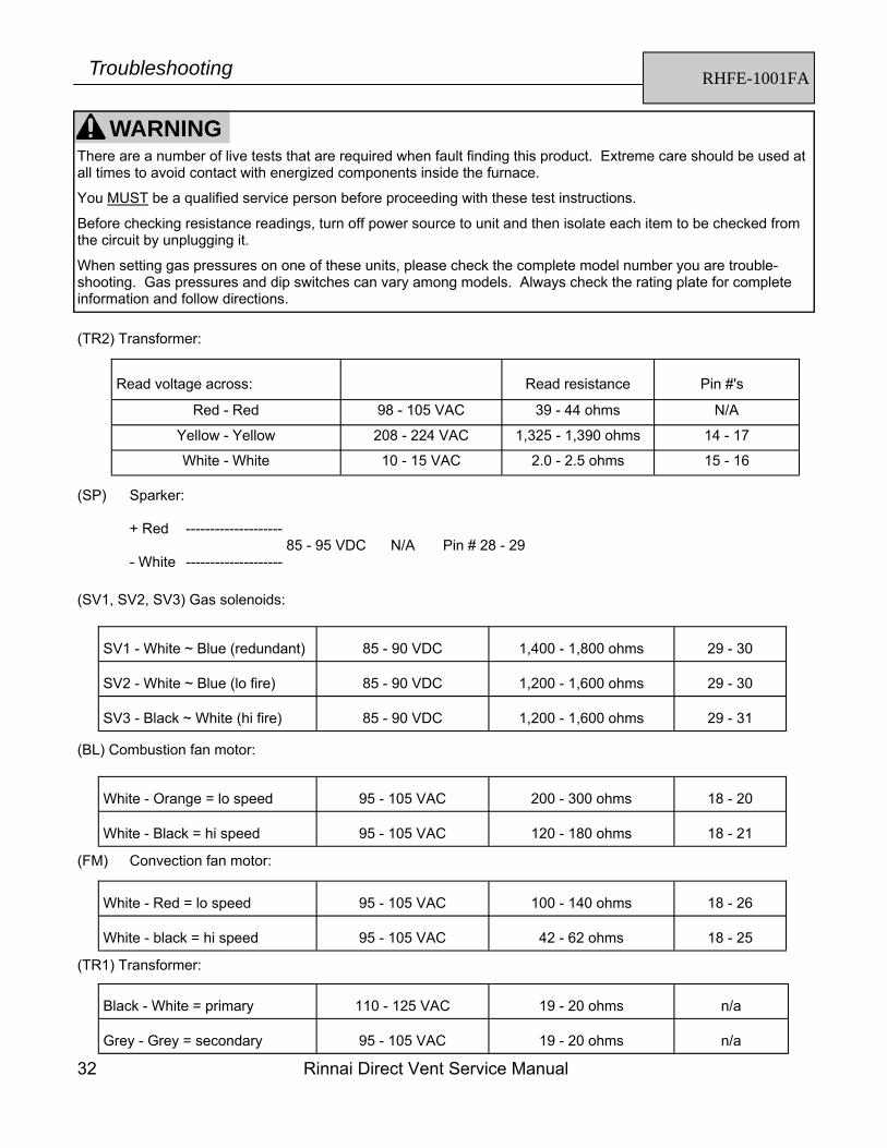
(TR) Transformer: Read Voltage across:
(SP) Sparker Board:
Set your voltage meter on the 400k scale, unplug the (5) pin connector on the sparker board. When reading across the two lugs the blue and red wire connect to, you should read somewhere between 100k and 120k ohms of resistance. When checking the spark sensing circuit, check across the orange wire (pin #35) and grey wire (pin #32) on your 40 VDC scale. You should read between 4 - 5 VDC. During the spark this voltage will drop to approximately 0 VDC. Once unit ignites the voltage will go back up to 4 - 5 VDC.
(POV, SV1, and SV2) Gas valve solenoids:
*Remember, when reading the resistance of a solenoid coil, you should read across the lugs on the coil.
RHFE-431FA Series RHFE-556FA/FTRA Series
Troubleshooting
WARNING There are a number of live tests that are required when fault finding this product. Extreme care should be used at all times to avoid contact with energized components inside the furnace.
You MUST be a qualified service person before proceeding with these test instructions.
Before checking resistance readings, turn off power source to unit and then isolate each item to be checked from the circuit by unplugging it.
When setting gas pressures on one of these units, please check the complete model number you are trouble-shooting. Gas pressures and dip switches can vary among models. Always check the rating plate for complete information and follow directions.
Gray - Gray 4.5 VDC low fire to 11.5 VDC high fire 80 - 100 ohms 43 - 45
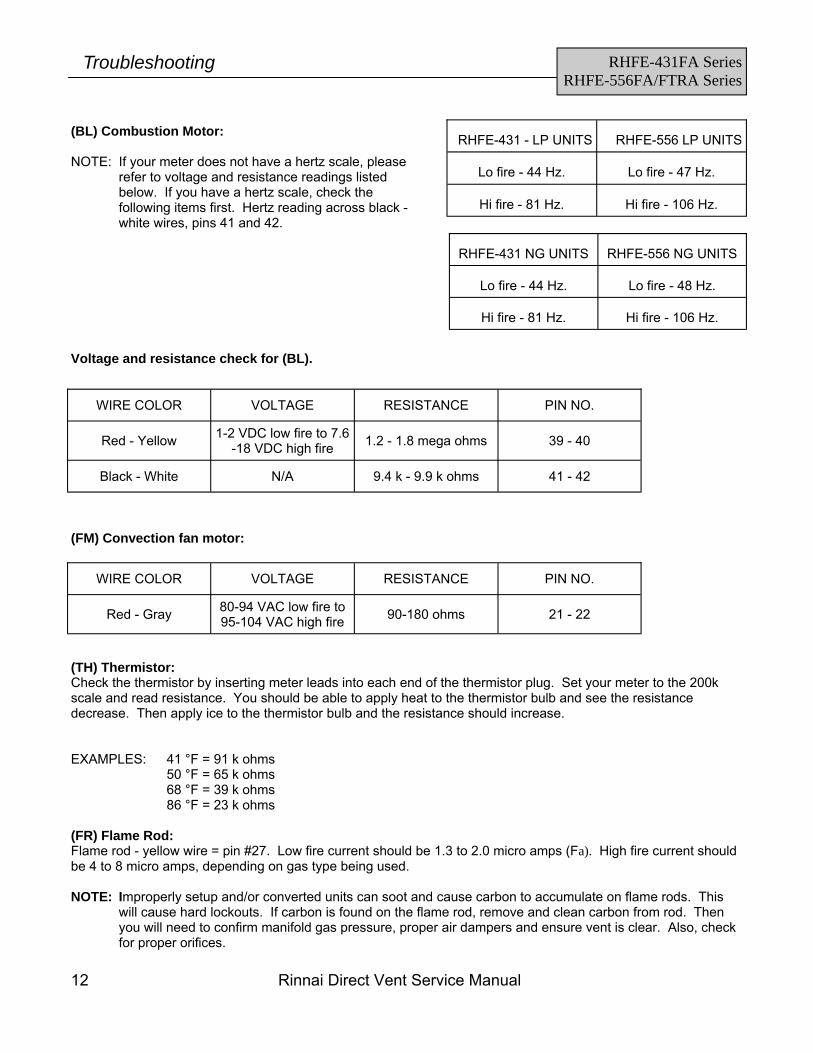
(BL) Combustion Motor: NOTE: If your meter does not have a hertz scale, please
refer to voltage and resistance readings listed below. If you have a hertz scale, check the following items first. Hertz reading across black - white wires, pins 41 and 42.
RHFE-431 - LP UNITS
RHFE-556 LP UNITS
Lo fire - 44 Hz.
Lo fire - 47 Hz.
Hi fire - 81 Hz.
Hi fire - 106 Hz.
Voltage and resistance check for (BL).
(TH) Thermistor: Check the thermistor by inserting meter leads into each end of the thermistor plug. Set your meter to the 200k scale and read resistance. You should be able to apply heat to the thermistor bulb and see the resistance decrease. Then apply ice to the thermistor bulb and the resistance should increase. EXAMPLES: 41 °F = 91 k ohms
50 °F = 65 k ohms 68 °F = 39 k ohms 86 °F = 23 k ohms
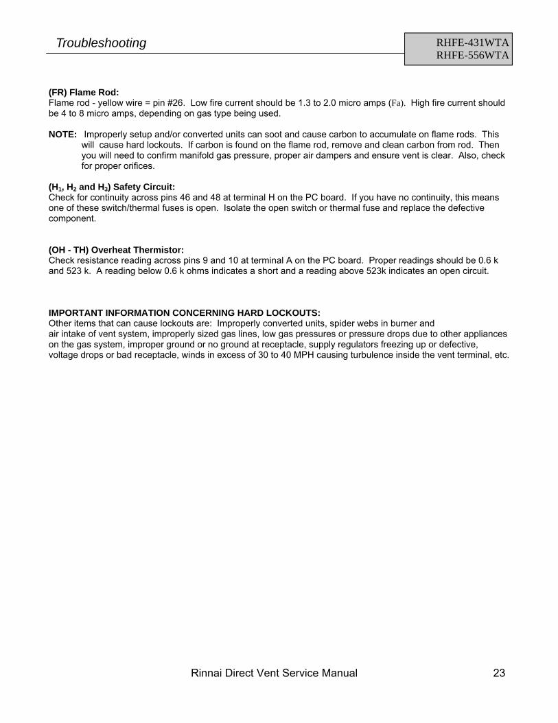
(FR) Flame Rod: Flame rod - yellow wire = pin #27. Low fire current should be 1.3 to 2.0 micro amps (Fa). High fire current should be 4 to 8 micro amps, depending on gas type being used. NOTE: Improperly setup and/or converted units can soot and cause carbon to accumulate on flame rods. This
will cause hard lockouts. If carbon is found on the flame rod, remove and clean carbon from rod. Then you will need to confirm manifold gas pressure, proper air dampers and ensure vent is clear. Also, check for proper orifices.
RHFE-431 NG UNITS
RHFE-556 NG UNITS
Lo fire - 44 Hz.
Lo fire - 48 Hz.
Hi fire - 81 Hz.
Hi fire - 106 Hz.
(FM) Convection fan motor:
Red - Yellow 1-2 VDC low fire to 7.6-18 VDC high fire 1.2 - 1.8 mega ohms 39 - 40
Black - White N/A 9.4 k - 9.9 k ohms 41 - 42
WIRE COLOR VOLTAGE RESISTANCE PIN NO.
WIRE COLOR VOLTAGE RESISTANCE PIN NO.
Red - Gray 80-94 VAC low fire to 95-104 VAC high fire 90-180 ohms 21 - 22
RHFE-431FA Series RHFE-556FA/FTRA Series
Troubleshooting
Rinnai Direct Vent Service Manual 13
(H1, H2 and H3) Safety Circuit: Check for continuity across pins 44 and 46 at terminal H on the PC board. If you have no continuity, this means one of these switch/thermal fuses is open. Replace defective component. (OH - TH) Overheat Thermistor: Check resistance reading across pins 12 and 13 at terminal A on the PC board. Proper readings should be 0.6 k and 523 k. A reading below 0.6 k ohms indicates a short and a reading above 523k indicates an open circuit. (MS) On/Off Control: To check to ensure the on/off button is functioning, unplug terminal I. Place (1) lead of your meter on the red wire for pin #66 and the other lead on the blue wire for pin#68. Now press the on/off button and you should be able to read continuity through this switch each time the button is pressed. (TB) Terminal Block: This terminal is located on the right rear upper portion of the unit. On direct vents the jumper should be across terminals 2 and 3. On units with vent extensions over four feet, this jumper should be across terminals 1 and 2. IMPORTANT INFORMATION CONCERNING HARD LOCKOUTS: Other items that can cause lockouts are: Improperly converted units, spider webs in burner and air intake of vent system, improperly sized gas lines, low gas pressures or pressure drops due to other appliances on the gas system, improper ground or no ground at receptacle, supply regulators freezing up or defective, voltage drops or bad receptacle, winds in excess of 30 to 40 MPH causing turbulence inside the vent terminal, etc.
RHFE-431FA Series RHFE-556FA/FTRA Series
Troubleshooting
14 Rinnai Direct Vent Service Manual
RHFE-431FA Series RHFE-556FA/FTRA
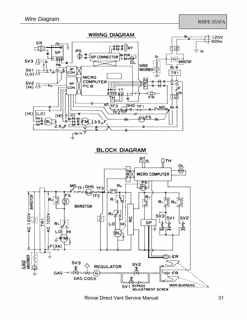
Wire Diagram
Rinnai Direct Vent Service Manual 15
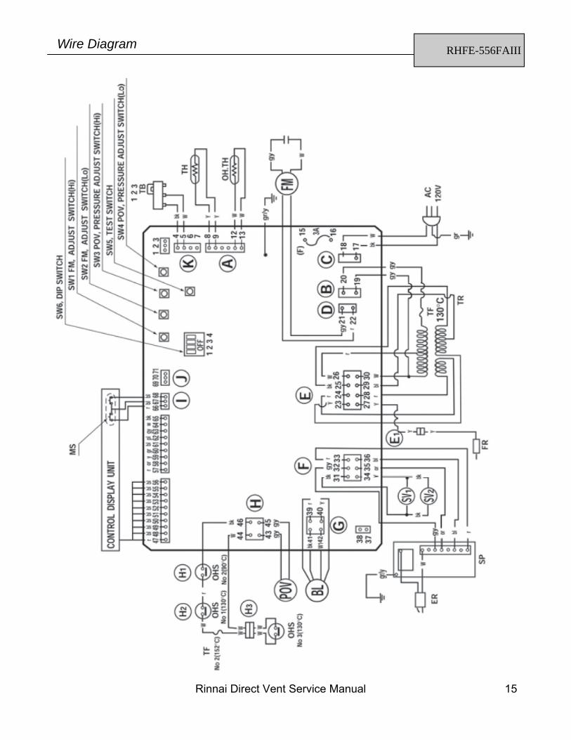
RHFE-556FAIII Wire Diagram
16 Rinnai Direct Vent Service Manual
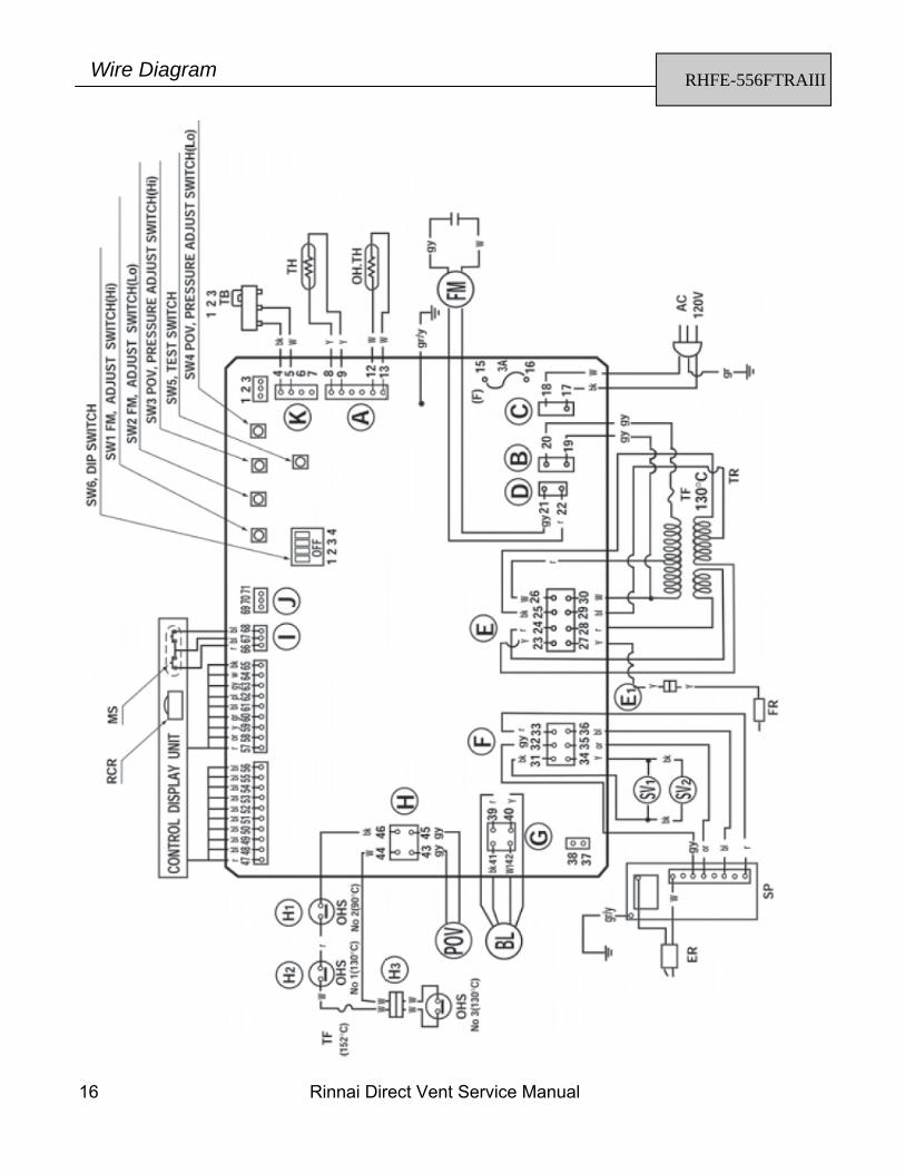
RHFE-556FTRAIII Wire Diagram
Rinnai Direct Vent Service Manual 17
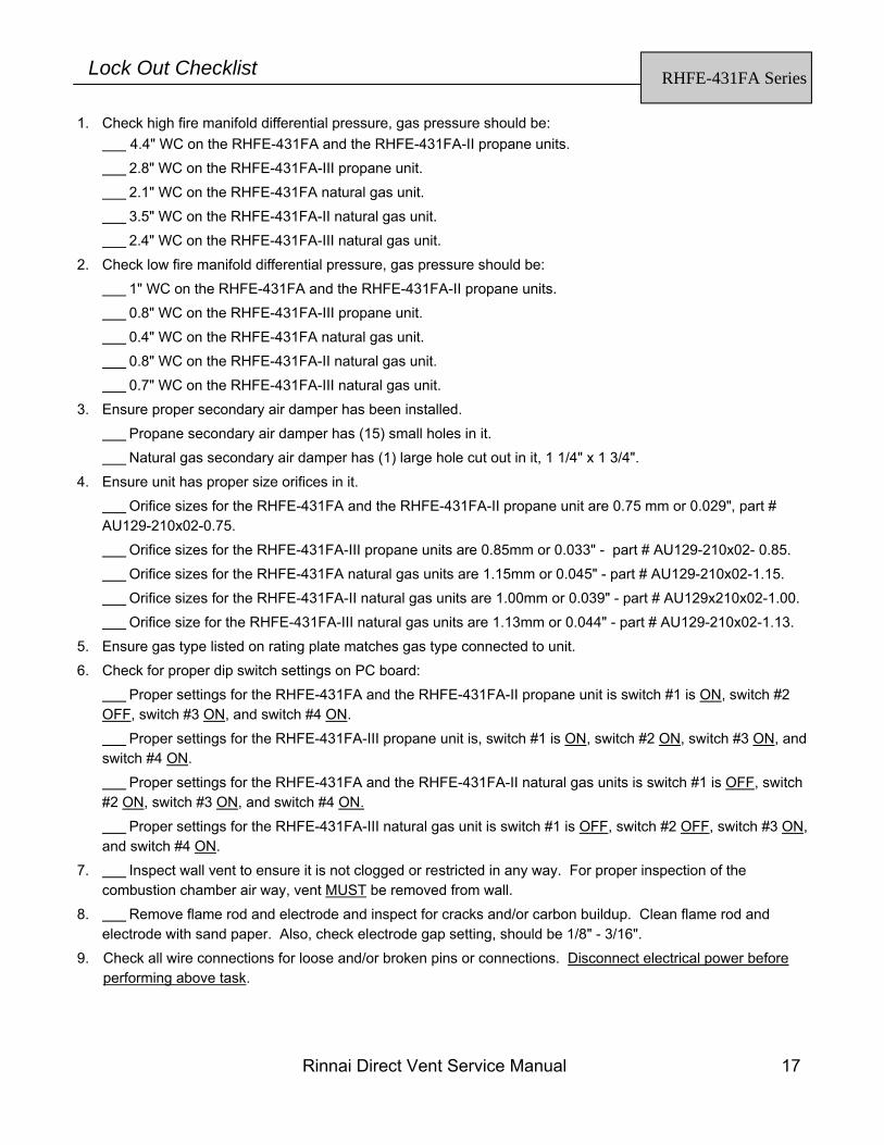
RHFE-431FA Series Lock Out Checklist
1. Check high fire manifold differential pressure, gas pressure should be: 4.4" WC on the RHFE-431FA and the RHFE-431FA-II propane units.
2.8" WC on the RHFE-431FA-III propane unit.
2.1" WC on the RHFE-431FA natural gas unit.
3.5" WC on the RHFE-431FA-II natural gas unit.
2.4" WC on the RHFE-431FA-III natural gas unit.
2. Check low fire manifold differential pressure, gas pressure should be:
1" WC on the RHFE-431FA and the RHFE-431FA-II propane units.
0.8" WC on the RHFE-431FA-III propane unit.
0.4" WC on the RHFE-431FA natural gas unit.
0.8" WC on the RHFE-431FA-II natural gas unit.
0.7" WC on the RHFE-431FA-III natural gas unit.
3. Ensure proper secondary air damper has been installed.
Propane secondary air damper has (15) small holes in it.
Natural gas secondary air damper has (1) large hole cut out in it, 1 1/4" x 1 3/4".
4. Ensure unit has proper size orifices in it.
Orifice sizes for the RHFE-431FA and the RHFE-431FA-II propane unit are 0.75 mm or 0.029", part # AU129-210x02-0.75.
Orifice sizes for the RHFE-431FA-III propane units are 0.85mm or 0.033" - part # AU129-210x02- 0.85.
Orifice sizes for the RHFE-431FA natural gas units are 1.15mm or 0.045" - part # AU129-210x02-1.15.
Orifice sizes for the RHFE-431FA-II natural gas units are 1.00mm or 0.039" - part # AU129x210x02-1.00.
Orifice size for the RHFE-431FA-III natural gas units are 1.13mm or 0.044" - part # AU129-210x02-1.13.
5. Ensure gas type listed on rating plate matches gas type connected to unit.
6. Check for proper dip switch settings on PC board:
Proper settings for the RHFE-431FA and the RHFE-431FA-II propane unit is switch #1 is ON, switch #2 OFF, switch #3 ON, and switch #4 ON.
Proper settings for the RHFE-431FA-III propane unit is, switch #1 is ON, switch #2 ON, switch #3 ON, and switch #4 ON.
Proper settings for the RHFE-431FA and the RHFE-431FA-II natural gas units is switch #1 is OFF, switch #2 ON, switch #3 ON, and switch #4 ON.
Proper settings for the RHFE-431FA-III natural gas unit is switch #1 is OFF, switch #2 OFF, switch #3 ON, and switch #4 ON.
7. Inspect wall vent to ensure it is not clogged or restricted in any way. For proper inspection of the combustion chamber air way, vent MUST be removed from wall.
8. Remove flame rod and electrode and inspect for cracks and/or carbon buildup. Clean flame rod and electrode with sand paper. Also, check electrode gap setting, should be 1/8" - 3/16".
9. Check all wire connections for loose and/or broken pins or connections. Disconnect electrical power before performing above task.
18 Rinnai Direct Vent Service Manual
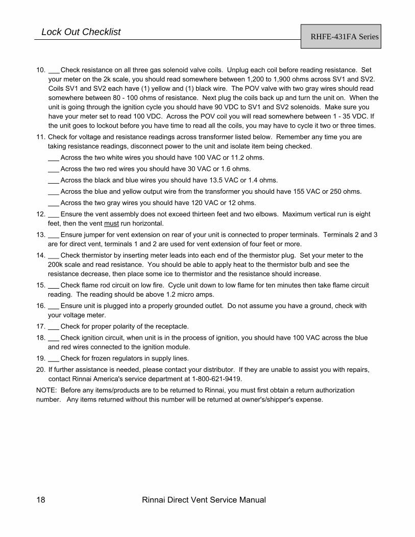
10. Check resistance on all three gas solenoid valve coils. Unplug each coil before reading resistance. Set your meter on the 2k scale, you should read somewhere between 1,200 to 1,900 ohms across SV1 and SV2. Coils SV1 and SV2 each have (1) yellow and (1) black wire. The POV valve with two gray wires should read somewhere between 80 - 100 ohms of resistance. Next plug the coils back up and turn the unit on. When the unit is going through the ignition cycle you should have 90 VDC to SV1 and SV2 solenoids. Make sure you have your meter set to read 100 VDC. Across the POV coil you will read somewhere between 1 - 35 VDC. If the unit goes to lockout before you have time to read all the coils, you may have to cycle it two or three times.
11. Check for voltage and resistance readings across transformer listed below. Remember any time you are taking resistance readings, disconnect power to the unit and isolate item being checked.
Across the two white wires you should have 100 VAC or 11.2 ohms.
Across the two red wires you should have 30 VAC or 1.6 ohms.
Across the black and blue wires you should have 13.5 VAC or 1.4 ohms.
Across the blue and yellow output wire from the transformer you should have 155 VAC or 250 ohms.
Across the two gray wires you should have 120 VAC or 12 ohms.
12. Ensure the vent assembly does not exceed thirteen feet and two elbows. Maximum vertical run is eight feet, then the vent must run horizontal.
13. Ensure jumper for vent extension on rear of your unit is connected to proper terminals. Terminals 2 and 3 are for direct vent, terminals 1 and 2 are used for vent extension of four feet or more.
14. Check thermistor by inserting meter leads into each end of the thermistor plug. Set your meter to the 200k scale and read resistance. You should be able to apply heat to the thermistor bulb and see the resistance decrease, then place some ice to thermistor and the resistance should increase.
15. Check flame rod circuit on low fire. Cycle unit down to low flame for ten minutes then take flame circuit reading. The reading should be above 1.2 micro amps.
16. Ensure unit is plugged into a properly grounded outlet. Do not assume you have a ground, check with your voltage meter.
17. Check for proper polarity of the receptacle.
18. Check ignition circuit, when unit is in the process of ignition, you should have 100 VAC across the blue and red wires connected to the ignition module.
19. Check for frozen regulators in supply lines.
20. If further assistance is needed, please contact your distributor. If they are unable to assist you with repairs, contact Rinnai America's service department at 1-800-621-9419.
NOTE: Before any items/products are to be returned to Rinnai, you must first obtain a return authorization number. Any items returned without this number will be returned at owner's/shipper's expense.
RHFE-431FA Series Lock Out Checklist
Rinnai Direct Vent Service Manual 19
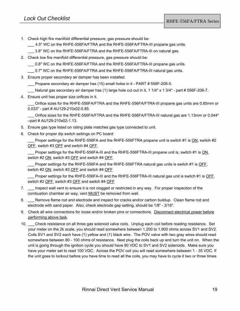
1. Check high fire manifold differential pressure, gas pressure should be: 4.5" WC on the RHFE-556FA/FTRA and the RHFE-556FA/FTRA-III propane gas units. 3.8" WC on the RHFE-556FA/FTRA and the RHFE-556FA/FTRA-III on natural gas. 2. Check low fire manifold differential pressure, gas pressure should be:
0.8" WC on the RHFE-556FA/FTRA and the RHFE-556FA/FTRA-III propane gas units. 0.7" WC on the RHFE-556FA/FTRA and the RHFE-556FA/FTRA-III natural gas units. 3. Ensure proper secondary air damper has been installed.
Propane secondary air damper has (15) small holes in it - PART # 556F-208-5.
Natural gas secondary air damper has (1) large hole cut out in it, 1 1/4" x 1 3/4" - part # 556F-208-7. 4. Ensure unit has proper size orifices in it.
Orifice sizes for the RHFE-556FA/FTRA and the RHFE-556FA/FTRA-III propane gas units are 0.85mm or 0.033" - part # AU129-210x02-0.85.
Orifice sizes for the RHFE-556FA/FTRA and the RHFE-556FA/FTRA-III natural gas are 1.13mm or 0.044" –part # AU129-210x02-1.13.
5. Ensure gas type listed on rating plate matches gas type connected to unit.
6. Check for proper dip switch settings on PC board:
Proper settings for the RHFE-556FA and the RHFE-556FTRA propane unit is switch #1 is ON, switch #2 OFF, switch #3 OFF and switch #4 OFF.
Proper settings for the RHFE-556FA-III and the RHFE-556FTRA-III propane unit is, switch #1 is ON, switch #2 ON, switch #3 OFF and switch #4 OFF.
Proper settings for the RHFE-556FA and the RHFE-556FTRA natural gas units is switch #1 is OFF, switch #2 ON, switch #3 OFF and switch #4 OFF
Proper settings for the RHFE-556FA-III and the RHFE-556FTRA-III natural gas unit is switch #1 is OFF, switch #2 OFF, switch #3 OFF and switch #4 OFF
7. Inspect wall vent to ensure it is not clogged or restricted in any way. For proper inspection of the combustion chamber air way, vent MUST be removed from wall.
8. Remove flame rod and electrode and inspect for cracks and/or carbon buildup. Clean flame rod and electrode with sand paper. Also, check electrode gap setting, should be 1/8" - 3/16".
9. Check all wire connections for loose and/or broken pins or connections. Disconnect electrical power before performing above task.
10. Check resistance on all three gas solenoid valve coils. Unplug each coil before reading resistance. Set your meter on the 2k scale, you should read somewhere between 1,200 to 1,900 ohms across SV1 and SV2. Coils SV1 and SV2 each have (1) yellow and (1) black wire. The POV valve with two gray wires should read somewhere between 80 - 100 ohms of resistance. Next plug the coils back up and turn the unit on. When the unit is going through the ignition cycle you should have 90 VDC to SV1 and SV2 solenoids. Make sure you have your meter set to read 100 VDC. Across the POV coil you will read somewhere between 1 - 35 VDC. If the unit goes to lockout before you have time to read all the coils, you may have to cycle it two or three times.
RHFE-556FA/FTRA Series Lock Out Checklist
20 Rinnai Direct Vent Service Manual
11. Check for voltage and resistance readings across transformer listed below. Remember any time you are taking resistance readings, disconnect power to the unit and isolate item being checked.
Across the two white wires you should have 100 VAC or 11.3 ohms.
Across the two red wires you should have 30 VAC or 1.6 ohms.
Across the black and blue wires you should have 13.5 VAC or 1.4 ohms.
Across the blue and yellow output wire from the transformer should have 155 VAC or 250 ohms.
Across the two gray wires you should have 120 VAC or 12 ohms.
12. Ensure the vent assembly does not exceed thirteen feet and two elbows. Maximum vertical run is eight feet, then the vent must run horizontal.
13. Ensure jumper for vent extension on rear of your unit is connected to proper terminals. Terminals 2 and 3 are for direct vent, terminals 1 and 2 are used for vent extension of four feet or more.
14. Check thermistor by inserting meter leads into each end of the thermistor plug. Set your meter to the 200k scale and read resistance. You should be able to apply heat to the thermistor bulb and see the resistance decrease, then place some ice to thermistor and the resistance should increase.
15. Check flame rod circuit on low fire. Cycle unit down to low flame for ten minutes then take flame circuit reading. The reading should be above 1.2 micro amps.
16. Ensure unit is plugged into a properly grounded outlet. Do not assume you have a ground, check with your voltage meter.
17. Check for proper polarity of the receptacle.
18. Check ignition circuit, when unit is in the process of ignition, you should have 100 VAC across the blue and red wires connected to the ignition module.
19. Check for frozen regulators in supply lines.
20. If further assistance is needed, please contact your distributor. If they are unable to assist you with repairs, contact Rinnai America's service department at 1-800-621-9419.
NOTE: Before any items/products are to be returned to Rinnai, you must first obtain a return authorization number. Any items returned without this number will be returned at owner's/shipper's expense.
RHFE-556FA/FTRA Series Lock Out Checklist
Rinnai Direct Vent Service Manual 21
RHFE-431WTA RHFE-556WTA
Troubleshooting
(TR) Transformer: Read Voltage across:
(SP) Sparker Board:
Set your voltage meter on the 400k scale, unplug the (5) pin connector on the sparker board. When reading across the two lugs the blue and red wire connect to, you should read somewhere between l00k and 120k ohms of resistance. When checking the spark sensing circuit, check across the orange wire (pin #35) and gray wire (pin #32) on your 40 VDC scale. You should read between 4 - 5 VDC. During the spark this voltage will drop to approximately 0 VDC. Once unit ignites the voltage will go back up to 4 - 5 VDC.
WARNING There are a number of live tests that are required when fault finding this product. Extreme care should be used at all times to avoid contact with energized components inside the furnace.
You MUST be a qualified service person before proceeding with these test instructions.
Before checking resistance readings, turn off power source to unit and then isolate each item to be checked from the circuit by unplugging it.
When setting gas pressures on one of these units, please check the complete model number you are trouble-shooting. Gas pressures and dip switches can vary among models. Always check the rating plate for complete information and follow directions.
22 Rinnai Direct Vent Service Manual
(POV, SV1, and SV2) Gas valve solenoids:
*Remember, when reading the resistance of a solenoid coil, you should read across the lugs on the coil.
RHFE-431WTA RHFE-556WTA
Troubleshooting
(BL) Combustion Motor: NOTE: If your meter does not have a hertz scale,
please refer to voltage and resistance readings listed below. If you have a hertz scale, check the following items first. Hertz reading across black - white wires, pins 41 and 42.
Voltage and resistance check for (BL).
(TH) Thermistor: Check the thermistor by inserting meter leads into each end of the thermistor plug. Set your meter to the 200k scale and read resistance. You should be able to apply heat to the thermistor bulb and see the resistance decrease. Then apply ice to the thermistor bulb and the resistance should increase. Pins 5 and 6 on the P.C. board. EXAMPLES: 41 ºF = 91 k ohms
50 ºF = 65 k ohms 68 ºF = 39 k ohms 86 ºF = 23 k ohms
(FM) Convection fan motor:
RHFE-431 - LP UNITS
RHFE-556 LP UNITS
Lo fire - 46 Hz.
Lo fire - 47 Hz.
Hi fire - 82 Hz.
Hi fire - 106 Hz.
RHFE-431 NG UNITS
RHFE-556 NG UNITS
Lo fire - 62 Hz.
Lo fire - 48 Hz.
Hi fire - 81 Hz.
Hi fire - 106 Hz.
Red - Yellow 1-2 VDC low fire to 7.6-18 VDC high fire 1.2 - 1.8 mega ohms 43 - 44
Black - White N/A 9.4 k - 9.9 k ohms 41 - 42
WIRE COLOR VOLTAGE RESISTANCE PIN NO.
WIRE COLOR VOLTAGE RESISTANCE PIN NO.
Red - Gray 80-94 VAC low fire to 95-104 VAC high fire 90-180 ohms 19 - 20
Gray - Gray 4.5 VDC low fire to 11.5 VDC high fire 80 - 100 ohms 45 - 47
(FR) Flame Rod: Flame rod - yellow wire = pin #26. Low fire current should be 1.3 to 2.0 micro amps (Fa). High fire current should be 4 to 8 micro amps, depending on gas type being used. NOTE: Improperly setup and/or converted units can soot and cause carbon to accumulate on flame rods. This
will cause hard lockouts. If carbon is found on the flame rod, remove and clean carbon from rod. Then you will need to confirm manifold gas pressure, proper air dampers and ensure vent is clear. Also, check for proper orifices.
(H1, H2 and H3) Safety Circuit: Check for continuity across pins 46 and 48 at terminal H on the PC board. If you have no continuity, this means one of these switch/thermal fuses is open. Isolate the open switch or thermal fuse and replace the defective component. (OH - TH) Overheat Thermistor: Check resistance reading across pins 9 and 10 at terminal A on the PC board. Proper readings should be 0.6 k and 523 k. A reading below 0.6 k ohms indicates a short and a reading above 523k indicates an open circuit. IMPORTANT INFORMATION CONCERNING HARD LOCKOUTS: Other items that can cause lockouts are: Improperly converted units, spider webs in burner and air intake of vent system, improperly sized gas lines, low gas pressures or pressure drops due to other appliances on the gas system, improper ground or no ground at receptacle, supply regulators freezing up or defective, voltage drops or bad receptacle, winds in excess of 30 to 40 MPH causing turbulence inside the vent terminal, etc.
RHFE-431WTA RHFE-556WTA
Troubleshooting
24 Rinnai Direct Vent Service Manual
RHFE-431WTA Wire Diagram
Rinnai Direct Vent Service Manual 25
RHFE-556WTA Wire Diagram
26 Rinnai Direct Vent Service Manual
RHFE-431WTA RHFE-556WTA
Lockout Checklist
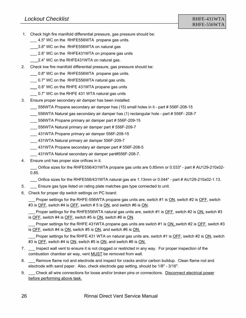
1. Check high fire manifold differential pressure, gas pressure should be: 4.5" WC on the RHFE556WTA propane gas units.
3.8" WC on the RHFE556WTA on natural gas
2.8” WC on the RHFE431WTA on propane gas units
2.4” WC on the RHFE431WTA on natural gas.
2. Check low fire manifold differential pressure, gas pressure should be:
0.8" WC on the RHFE556WTA propane gas units.
0.7" WC on the RHFE556WTA natural gas units.
___ 0.8” WC on the RHFE 431WTA propane gas units
___ 0.7” WC on the RHFE 431 WTA natural gas units
3. Ensure proper secondary air damper has been installed.
556WTA Propane secondary air damper has (15) small holes in it - part # 556F-208-15
556WTA Natural gas secondary air damper has (1) rectangular hole - part # 556F- 208-7
___ 556WTA Propane primary air damper part # 556F-209-15
___ 556WTA Natural primary air damper part # 556F-209-7
___ 431WTA Propane primary air damper 556F-209-15
___ 431WTA Natural primary air damper 556F-209-7
___ 431WTA Propane secondary air damper part # 556F-208-5
___ 431WTA Natural secondary air damper part#556F-208-7.
4. Ensure unit has proper size orifices in it.
Orifice sizes for the RHFE556/431WTA propane gas units are 0.85mm or 0.033" - part # AU129-210x02-0.85.
Orifice sizes for the RHFE556/431WTA natural gas are 1.13mm or 0.044" - part # AU129-210x02-1.13.
5. Ensure gas type listed on rating plate matches gas type connected to unit.
6. Check for proper dip switch settings on PC board:
___ Proper settings for the RHFE-556WTA propane gas units are, switch #1 is ON, switch #2 is OFF, switch #3 is OFF, switch #4 is OFF, switch # 5 is ON, and switch #6 is ON.
___ Proper settings for the RHFE556WTA natural gas units are, switch #1 is OFF, switch #2 is ON, switch #3 is OFF, switch #4 is OFF, switch #5 is ON, switch #6 is ON.
___ Proper settings for the RHFE 431WTA propane gas units are switch #1 is ON, switch #2 is OFF, switch #3 is OFF, switch #4 is ON, switch #5 is ON, and switch #6 is ON.
___ Proper settings for the RHFE 431 WTA on natural gas units are, switch #1 is OFF, switch #2 is ON, switch #3 is OFF, switch #4 is ON, switch #5 is ON, and switch #6 is ON.
7. Inspect wall vent to ensure it is not clogged or restricted in any way. For proper inspection of the combustion chamber air way, vent MUST be removed from wall.
8. Remove flame rod and electrode and inspect for cracks and/or carbon buildup. Clean flame rod and electrode with sand paper. Also, check electrode gap setting, should be 1/8" - 3/16".
9. Check all wire connections for loose and/or broken pins or connections. Disconnect electrical power before performing above task.
Rinnai Direct Vent Service Manual 27
RHFE-431WTA RHFE-556WTA
Lockout Checklist
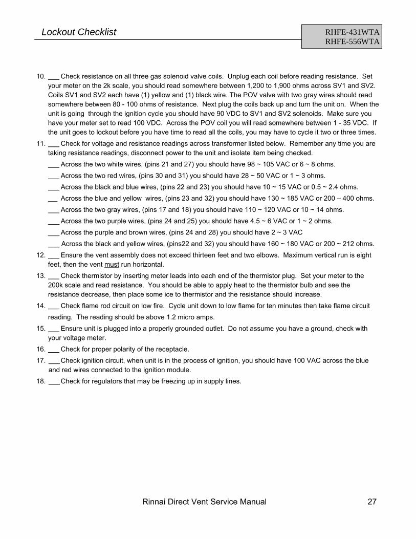
10. Check resistance on all three gas solenoid valve coils. Unplug each coil before reading resistance. Set your meter on the 2k scale, you should read somewhere between 1,200 to 1,900 ohms across SV1 and SV2. Coils SV1 and SV2 each have (1) yellow and (1) black wire. The POV valve with two gray wires should read somewhere between 80 - 100 ohms of resistance. Next plug the coils back up and turn the unit on. When the unit is going through the ignition cycle you should have 90 VDC to SV1 and SV2 solenoids. Make sure you have your meter set to read 100 VDC. Across the POV coil you will read somewhere between 1 - 35 VDC. If the unit goes to lockout before you have time to read all the coils, you may have to cycle it two or three times.
11. Check for voltage and resistance readings across transformer listed below. Remember any time you are taking resistance readings, disconnect power to the unit and isolate item being checked.
Across the two white wires, (pins 21 and 27) you should have 98 ~ 105 VAC or 6 ~ 8 ohms.
Across the two red wires, (pins 30 and 31) you should have 28 ~ 50 VAC or 1 ~ 3 ohms.
Across the black and blue wires, (pins 22 and 23) you should have 10 ~ 15 VAC or 0.5 ~ 2.4 ohms.
Across the blue and yellow wires, (pins 23 and 32) you should have 130 ~ 185 VAC or 200 – 400 ohms.
Across the two gray wires, (pins 17 and 18) you should have 110 ~ 120 VAC or 10 ~ 14 ohms.
___ Across the two purple wires, (pins 24 and 25) you should have 4.5 ~ 6 VAC or 1 ~ 2 ohms.
___ Across the purple and brown wires, (pins 24 and 28) you should have 2 ~ 3 VAC
___ Across the black and yellow wires, (pins22 and 32) you should have 160 ~ 180 VAC or 200 ~ 212 ohms.
12. Ensure the vent assembly does not exceed thirteen feet and two elbows. Maximum vertical run is eight feet, then the vent must run horizontal.
13. Check thermistor by inserting meter leads into each end of the thermistor plug. Set your meter to the 200k scale and read resistance. You should be able to apply heat to the thermistor bulb and see the resistance decrease, then place some ice to thermistor and the resistance should increase.
14. Check flame rod circuit on low fire. Cycle unit down to low flame for ten minutes then take flame circuit
reading. The reading should be above 1.2 micro amps.
15. Ensure unit is plugged into a properly grounded outlet. Do not assume you have a ground, check with your voltage meter.
16. Check for proper polarity of the receptacle.
17. Check ignition circuit, when unit is in the process of ignition, you should have 100 VAC across the blue and red wires connected to the ignition module.
18. Check for regulators that may be freezing up in supply lines.
White - White 15 VAC secondary side 1.9 - 2.3 ohms
Read voltage across: Brown --------------------
85 - 95 VDC Purple --------------------
Check from the white wire in the molex connector at the ignitor transformer to ground. You should read 1.5 - 1.8 VDC when the unit is trying to ignite.
WARNING There are a number of live tests that are required when fault finding this product. Extreme care should be used at all times to avoid contact with energized components inside the furnace.
You MUST be a qualified service person before proceeding with these test instructions.
Before checking resistance readings, turn off power source to unit and then isolate each item to be checked from the circuit by unplugging it.
When setting gas pressures on one of these units, please check the complete model number you are trouble-shooting. Gas pressures and dip switches can vary among models. Always check the rating plate for complete information and follow directions.
Rinnai Direct Vent Service Manual 29
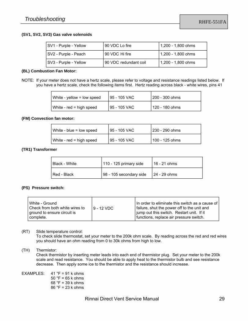
(SV1, SV2, SV3) Gas valve solenoids
(BL) Combustion Fan Motor: NOTE: If your meter does not have a hertz scale, please refer to voltage and resistance readings listed below. If
you have a hertz scale, check the following items first. Hertz reading across black - white wires, pins 41
(FM) Convection fan motor:
RHFE-551FA Troubleshooting
SV1 - Purple - Yellow 90 VDC Lo fire 1,200 - 1,800 ohms
SV2 - Purple - Peach 90 VDC Hi fire 1,200 - 1,800 ohms
White - Ground Check from both white wires to ground to ensure circuit is complete.
9 - 12 VDC
In order to eliminate this switch as a cause of failure, shut the power off to the unit and jump out this switch. Restart unit. If it functions, replace air pressure switch.
(RT) Slide temperature control: To check slide thermostat, set your meter to the 200k ohm scale. By reading across the red and red wires you should have an ohm reading from 0 to 30k ohms from high to low.
(TH) Thermistor:
Check thermistor by inserting meter leads into each end of thermistor plug. Set your meter to the 200k scale and read resistance. You should be able to apply heat to the thermistor bulb and see resistance decrease. Then apply some ice to the thermistor and the resistance should increase.
EXAMPLES: 41 °F = 91 k ohms 50 °F = 65 k ohms 68 °F = 39 k ohms 86 °F = 23 k ohms
30 Rinnai Direct Vent Service Manual
(FR) Flame Rod:
Flame rod - yellow wire. Low fire flame circuit should be somewhere around 1.2 to 1.8 micro amps, depending on gas type being used. High fire flame circuit should be between 4 - 8 micro amps.
*NOTE: Improperly setup units can cause flame rods to carbon up. This can cause a hard lockout. If
carbon is found on the flame rod, remove the rod and clean it. Then you need to reconfirm the manifold gas pressure, check air shutter setting, by-pass restrictor screw size and all orifices for proper sizing. Also, the burner should be removed and cleaned.
Safety Circuit Test: TF1, TF2, TF3, OHS, and M.S. Unplug the black and red wire connector off of TR1 transformer, Then unplug the nine pin connector next to the PC board. Now insert (1) lead of your meter into the grey wire connection at the nine pin connector and the other lead to the black wire at the connection at transformer TR1. Set your meter to read continuity. Turn the control knob to the on position. You should read continuity through the safety circuit at this time. If not, you need to confirm which switch is defective and replace that component. To check voltage through the safety circuit, place your leads in the black wire connection at transformer TR1 and the grey wire connection at the nine pin connector at the PC board. With all components reconnected, turn the control knob to the on position. You should read 0 volts AC across these two points. If you read anything above 1 VAC, there is a bad switch somewhere in this part of the circuit. IMPORTANT INFORMATION CONCERNING HARD LOCKOUTS Other items that can cause hard lockouts are: improper conversions, spider webs in burner and/or vent assembly, improperly sized gas lines, low pressure or pressure drops due to other appliances on gas system, improper ground or no ground at receptacle, supply regulator freezing up or defective, voltage drops or bad receptacles, winds in excess of 40 MPH setting off pressure switch, etc.
WARNING There are a number of live tests that are required when fault finding this product. Extreme care should be used at all times to avoid contact with energized components inside the furnace.
You MUST be a qualified service person before proceeding with these test instructions.
Before checking resistance readings, turn off power source to unit and then isolate each item to be checked from the circuit by unplugging it.
When setting gas pressures on one of these units, please check the complete model number you are trouble-shooting. Gas pressures and dip switches can vary among models. Always check the rating plate for complete information and follow directions.
Rinnai Direct Vent Service Manual 33
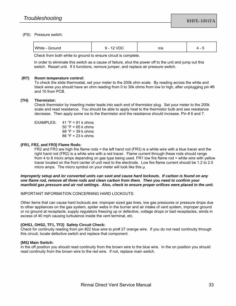
(PS) Pressure switch:
White - Ground
9 - 12 VDC
n/a
4 - 5
(RT) Room temperature control: To check the slide thermostat, set your meter to the 200k ohm scale. By reading across the white and black wires you should have an ohm reading from 0 to 30k ohms from low to high, after unplugging pin #9 and 10 from PCB.
(TH) Thermistor:
Check thermistor by inserting meter leads into each end of thermistor plug. Set your meter to the 200k scale and read resistance. You should be able to apply heat to the thermistor bulb and see resistance decrease. Then apply some ice to the thermistor and the resistance should increase. Pin # 6 and 7.
EXAMPLES: 41 °F = 91 k ohms 50 °F = 65 k ohms 68 °F = 39 k ohms 86 °F = 23 k ohms
(FR1, FR2, and FR3) Flame Rods:
FR2 and FR3 are high fire flame rods = the left hand rod (FR3) is a white wire with a blue tracer and the right hand rod (FR2) is a white wire with a red tracer. Flame current through these rods should range from 4 to 8 micro amps depending on gas type being used. FR1 low fire flame rod = white wire with yellow tracer located on the front center of unit next to the electrode. Low fire flame current should be 1.2 to 2.0 micro amps. The micro symbol on your meter will look like this µ.
Improperly setup and /or converted units can soot and cause hard lockouts. If carbon is found on any one flame rod, remove all three rods and clean carbon from them. Then you need to confirm your manifold gas pressure and air rod settings. Also, check to ensure proper orifices were placed in the unit. IMPORTANT INFORMATION CONCERNING HARD LOCKOUTS: Other items that can cause hard lockouts are: improper sized gas lines, low gas pressures or pressure drops due to other appliances on the gas system, spider webs in the burner and air intake of vent system, improper ground or no ground at receptacle, supply regulators freezing up or defective, voltage drops or bad receptacles, winds in excess of 40 mph causing turbulence inside the vent terminal, etc. (OHS1, OHS2, TF1, TF2) Safety Circuit Check: Check for continuity reading from pin #22 blue wire to pin# 27 orange wire. If you do not read continuity through this circuit, locate defective switch and replace that component. (MS) Main Switch: In the off position you should read continuity from the brown wire to the blue wire. In the on position you should read continuity from the brown wire to the red wire. If not, replace main switch.
RHFE-1001FA Troubleshooting
Check from both white to ground to ensure circuit is complete.
In order to eliminate this switch as a cause of failure, shut the power off to the unit and jump out this switch. Resart unit. If it functions, remove jumper, and replace air pressure switch.
WARNING There are a number of live tests that are required when fault finding this product. Extreme care should be used at all times to avoid contact with energized components inside the furnace.
You MUST be a qualified service person before proceeding with these test instructions.
Before checking resistance readings, turn off power source to unit and then isolate each item to be checked from the circuit by unplugging it.
When setting gas pressures on one of these units, please check the complete model number you are trouble-shooting. Gas pressures and dip switches can vary among models. Always check the rating plate for complete information and follow directions.
36 Rinnai Direct Vent Service Manual
RHFE1001FA/VA Troubleshooting
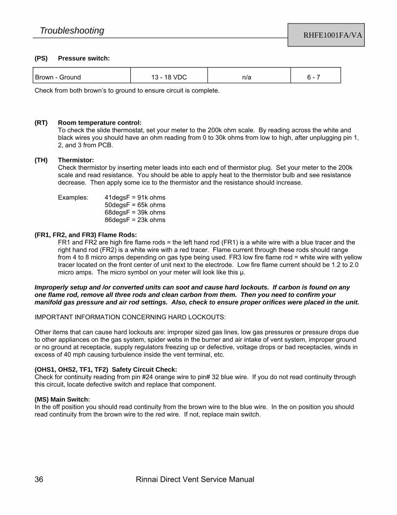
(PS) Pressure switch: Brown - Ground
13 - 18 VDC
n/a
6 - 7
(RT) Room temperature control: To check the slide thermostat, set your meter to the 200k ohm scale. By reading across the white and black wires you should have an ohm reading from 0 to 30k ohms from low to high, after unplugging pin 1, 2, and 3 from PCB.
(TH) Thermistor:
Check thermistor by inserting meter leads into each end of thermistor plug. Set your meter to the 200k scale and read resistance. You should be able to apply heat to the thermistor bulb and see resistance decrease. Then apply some ice to the thermistor and the resistance should increase. Examples: 41degsF = 91k ohms
FR1 and FR2 are high fire flame rods = the left hand rod (FR1) is a white wire with a blue tracer and the right hand rod (FR2) is a white wire with a red tracer. Flame current through these rods should range from 4 to 8 micro amps depending on gas type being used. FR3 low fire flame rod = white wire with yellow tracer located on the front center of unit next to the electrode. Low fire flame current should be 1.2 to 2.0 micro amps. The micro symbol on your meter will look like this µ.
Improperly setup and /or converted units can soot and cause hard lockouts. If carbon is found on any one flame rod, remove all three rods and clean carbon from them. Then you need to confirm your manifold gas pressure and air rod settings. Also, check to ensure proper orifices were placed in the unit. IMPORTANT INFORMATION CONCERNING HARD LOCKOUTS: Other items that can cause hard lockouts are: improper sized gas lines, low gas pressures or pressure drops due to other appliances on the gas system, spider webs in the burner and air intake of vent system, improper ground or no ground at receptacle, supply regulators freezing up or defective, voltage drops or bad receptacles, winds in excess of 40 mph causing turbulence inside the vent terminal, etc. (OHS1, OHS2, TF1, TF2) Safety Circuit Check: Check for continuity reading from pin #24 orange wire to pin# 32 blue wire. If you do not read continuity through this circuit, locate defective switch and replace that component. (MS) Main Switch: In the off position you should read continuity from the brown wire to the blue wire. In the on position you should read continuity from the brown wire to the red wire. If not, replace main switch.
Check from both brown’s to ground to ensure circuit is complete.
Rinnai Direct Vent Service Manual 37
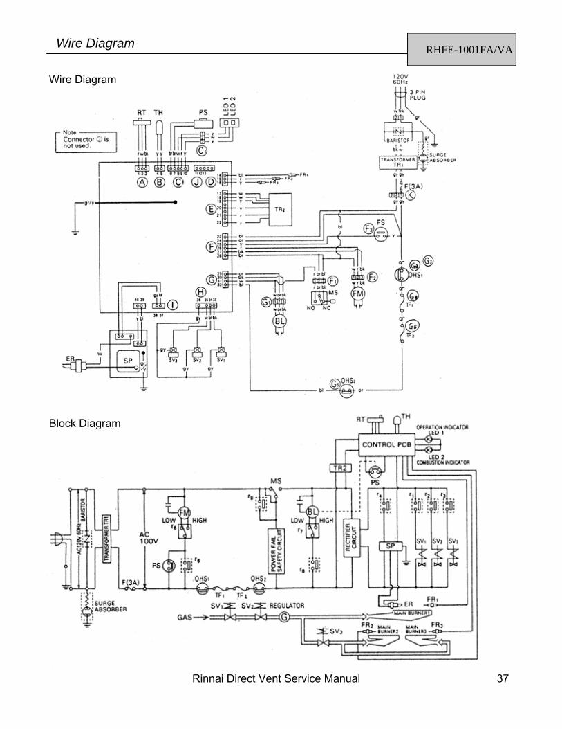
RHFE-1001FA/VA Wire Diagram
Wire Diagram
Block Diagram
38 Rinnai Direct Vent Service Manual
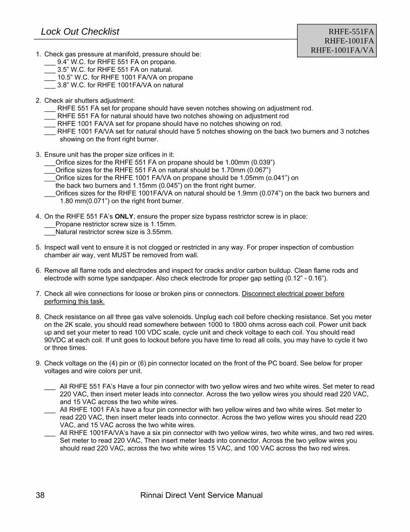
1. Check gas pressure at manifold, pressure should be: ___ 9.4” W.C. for RHFE 551 FA on propane. ___ 3.5” W.C. for RHFE 551 FA on natural. ___ 10.5” W.C. for RHFE 1001 FA/VA on propane ___ 3.8” W.C. for RHFE 1001FA/VA on natural
2. Check air shutters adjustment:
___ RHFE 551 FA set for propane should have seven notches showing on adjustment rod. ___ RHFE 551 FA for natural should have two notches showing on adjustment rod ___ RHFE 1001 FA/VA set for propane should have no notches showing on rod. ___ RHFE 1001 FA/VA set for natural should have 5 notches showing on the back two burners and 3 notches
showing on the front right burner.
3. Ensure unit has the proper size orifices in it: ___Orifice sizes for the RHFE 551 FA on propane should be 1.00mm (0.039”) ___Orifice sizes for the RHFE 551 FA on natural should be 1.70mm (0.067”) ___Orifice sizes for the RHFE 1001 FA/VA on propane should be 1.05mm (o.041”) on the back two burners and 1.15mm (0.045”) on the front right burner. ___Orifices sizes for the RHFE 1001FA/VA on natural should be 1.9mm (0.074”) on the back two burners and
1.80 mm(0.071”) on the right front burner.
4. On the RHFE 551 FA’s ONLY, ensure the proper size bypass restrictor screw is in place: ___Propane restrictor screw size is 1.15mm. ___Natural restrictor screw size is 3.55mm.
5. Inspect wall vent to ensure it is not clogged or restricted in any way. For proper inspection of combustion
chamber air way, vent MUST be removed from wall.
6. Remove all flame rods and electrodes and inspect for cracks and/or carbon buildup. Clean flame rods and electrode with some type sandpaper. Also check electrode for proper gap setting (0.12” - 0.16”).
7. Check all wire connections for loose or broken pins or connectors. Disconnect electrical power before
performing this task.
8. Check resistance on all three gas valve solenoids. Unplug each coil before checking resistance. Set you meter on the 2K scale, you should read somewhere between 1000 to 1800 ohms across each coil. Power unit back up and set your meter to read 100 VDC scale, cycle unit and check voltage to each coil. You should read 90VDC at each coil. If unit goes to lockout before you have time to read all coils, you may have to cycle it two or three times.
9. Check voltage on the (4) pin or (6) pin connector located on the front of the PC board. See below for proper
voltages and wire colors per unit.
___ All RHFE 551 FA’s Have a four pin connector with two yellow wires and two white wires. Set meter to read 220 VAC, then insert meter leads into connector. Across the two yellow wires you should read 220 VAC, and 15 VAC across the two white wires.
___ All RHFE 1001 FA’s have a four pin connector with two yellow wires and two white wires. Set meter to read 220 VAC, then insert meter leads into connector. Across the two yellow wires you should read 220 VAC, and 15 VAC across the two white wires.
___ All RHFE 1001FA/VA’s have a six pin connector with two yellow wires, two white wires, and two red wires. Set meter to read 220 VAC, Then insert meter leads into connector. Across the two yellow wires you should read 220 VAC, across the two white wires 15 VAC, and 100 VAC across the two red wires.
RHFE-551FA RHFE-1001FA
RHFE-1001FA/VA
Lock Out Checklist
Rinnai Direct Vent Service Manual 39
• Ensure the air pressure switch is functioning properly. Ohm out the micro-switch located on the pressure
switch. Continuity will be read on meter when closed position. • Ensure the vent system does not exceed fifteen feet total run, not exceeding 8 feet vertically, with no more than
two bent elbows. • Check slide thermostat, set your meter to the 200K ohm scale. By reading across the white and black wires,
you should have and ohm range from 0 to 30 ohms from low to high on the RHFE 1001 units. One the RHFE 551 FA units read from red to red wires you should read 30 ohms from low to 0 ohms on high.
• Check thermistor operation by inserting meter leads into each end of thermistor plug. Disconnect yellow to yellow from PCB, set your meter on the 200K scale. Your should be able to apply heat to the thermistor bulb and see resistances decrease. Place some ice on thermistor bulb and resistances should increase.
10. Check current on all flame rods:
___RHFE 551 FA only has one flame rod. On the low burner this current should be 1to 2 micro amps and on high, current should be 5 to 6 micro amps. ___RHFE 1001 FA and RHFE 1001FA/VA uses only one flame rod on low fire. This is the front flame rod nest to the electrode. Current on this rod should be 1 to 2 micro amps on start up. There are three total flame rods on these units, and on high 5 to 6 micro amps
should be measured.
YOU MUST ENSURE UNIT IS GROUNDED !!
RHFE-551FA RHFE-1001FA
RHFE-1001FA/VA
Lock Out Checklist
40 Rinnai Direct Vent Service Manual
RHFE-201FA Troubleshooting
(AC IN) (Connector B)
Black-White 120 VAC CONNECTOR B Pin # 1-2
Black-Ground 120 VAC Pin #2-Ground
White-Ground 0 VAC Pin #1-Ground
(TR) Transformer: (Connector C) (AC Out)
Read voltage across: Voltage Potential Read resistance Pin Numbers
Grey-Grey 90-110 VAC 3-6Ω Pin #1-7
Red-Yellow 30-42 VAC 0.8-1.5Ω Pin #4-5
Blank pin-Grey 15-21 VAC 0.6-1.2Ω Pin #6-7
Grey-Black 180-220VAC 155-260Ω Pin #7-8
(SP) Sparker: (Connector D) (Voltage potential while Sparking)
Read voltage across: Voltage Potential Read resistance Pin Numbers
Red-Blue 85-100 VAC 100K-120K Ω Pin #3-6 The spark must be sensed as being at the correct location and intensity before it will allow the gas valve to open. Check across Pin # 1-2 at Connector F and you should read 4-6 VDC potential. When sparking, if the spark is in the right location and intensity the voltage potential will drop to almost 0 (zero) and then return to the 4-6 VDC potential.
(SV1 and SV2) Main Solenoid Valves: (Connector D)
Read voltage across: Voltage Potential Read resistance Pin Numbers
Black-Yellow 85-90 VDC 700-1000 Ω Pin #1-4
*Resistance across each coils terminals should be 1400-2000 Ω when isolated.
(POV) Modulating Gas Valve (Connector G)
Read voltage across: Voltage Potential Read resistance Pin Numbers
Grey-Grey 6-16 VDC 80-90 Ω Pin #2-6
(BL) Combustion Blower Motor: (Connector G) DC Motor 37VDC 8 Watts
Read voltage across: Voltage Potential Read resistance Pin Numbers
Black-White 7-12 VDC 8K-10K Ω Pin #7-8
Yellow-White 4-5 VDC 4K-6K Ω Pin #4-8
Red-White 10-30 VDC N/A Pin # 3-8
WARNING There are a number of live tests that are required when fault finding this product. Extreme care should be used at all times to avoid contact with energized components inside the furnace.
You MUST be a qualified service person before proceeding with these test instructions.
Before checking resistance readings, turn off power source to unit and then isolate each item to be checked from the circuit by unplugging it.
When setting gas pressures on one of these units, please check the complete model number you are trouble-shooting. Gas pressures and dip switches can vary among models. Always check the rating plate for complete information and follow directions.
Rinnai Direct Vent Service Manual 41
RHFE-201FA Troubleshooting
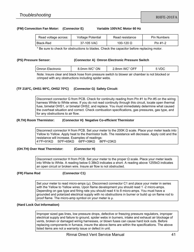
(FM) Convection Fan Motor: (Connector E) Variable 100VAC Motor 60 Hz
Read voltage across: Voltage Potential Read resistance Pin Numbers
Black-Red 37-105 VAC 100-120 Ω Pin #1-2
* Be sure to check for obstructions to blades. Check the capacitor before replacing motor.
(PS) Pressure Sensor: (Connector A) Omron Electronic Pressure Switch
Omron Electronic 8.0mm WC” ON 2.8mm WC” OFF 5 VDC
Note: Insure clear and black hose from pressure switch to blower air chamber is not blocked or crimped with any obstructions including spider webs.
Disconnect connector G from PCB. Check for continuity reading from Pin #1 to Pin #5 on the wiring harness White to White wires. If you do not read continuity through this circuit, locate open thermal fuse, bimetal OHS1, or bimetal OHS2, and replace. You must immediately determine what caused the overheat situation and correct. Check combustion specifications, gas pressures, gas type, and for any obstructions to air flow.
Disconnect connector H from PCB. Set your meter to the 200K Ω scale. Place your meter leads into Yellow to Yellow. Apply heat to the thermistor bulb. The resistance will decrease. Apply cold and the resistance will increase. Examples of readings: 41ºF=91KΩ 50ºF=65KΩ 68ºF=39KΩ 86ºF=23KΩ
(OH.TH) Over Heat Thermistor: (Connector H)
Disconnect connector H from PCB. Set your meter to the proper Ω scale. Place your meter leads into White to White. A reading below 0.38kΩ indicates a short. A reading above 1255kΩ indicates an open circuit or broken wire. Insure air flow is not obstructed.
(FR) Flame Rod (Connector C1)
Set your meter to read micro-amps (µ). Disconnect connector C1 and place your meter in series with the Yellow to Yellow wires. Upon flame development you should read 1 -2 micro-amps. Depending on gas type and firing rate you should read 4 to 8 micro-amps. You must have a grounded and polarized electrical supply with no obstructions in burner or build up on flame rod to proof flame. The micro-amp symbol on your meter is µ.
(Hard Lock Out Information)
Improper sized gas lines, low pressure drops, defective or freezing pressure regulators, improper electrical supply and failure to ground, spider webs in burners, intake and exhaust air blockage of vents, broken or damaged wiring harnesses, or blown fuses can cause hard lock outs. Before replacing components in furnace, insure the above items are within the specifications. The above listed items are not a warranty issue or defect in unit.
42 Rinnai Direct Vent Service Manual
RHFE-201FA Wire Diagram
Rinnai Direct Vent Service Manual 43
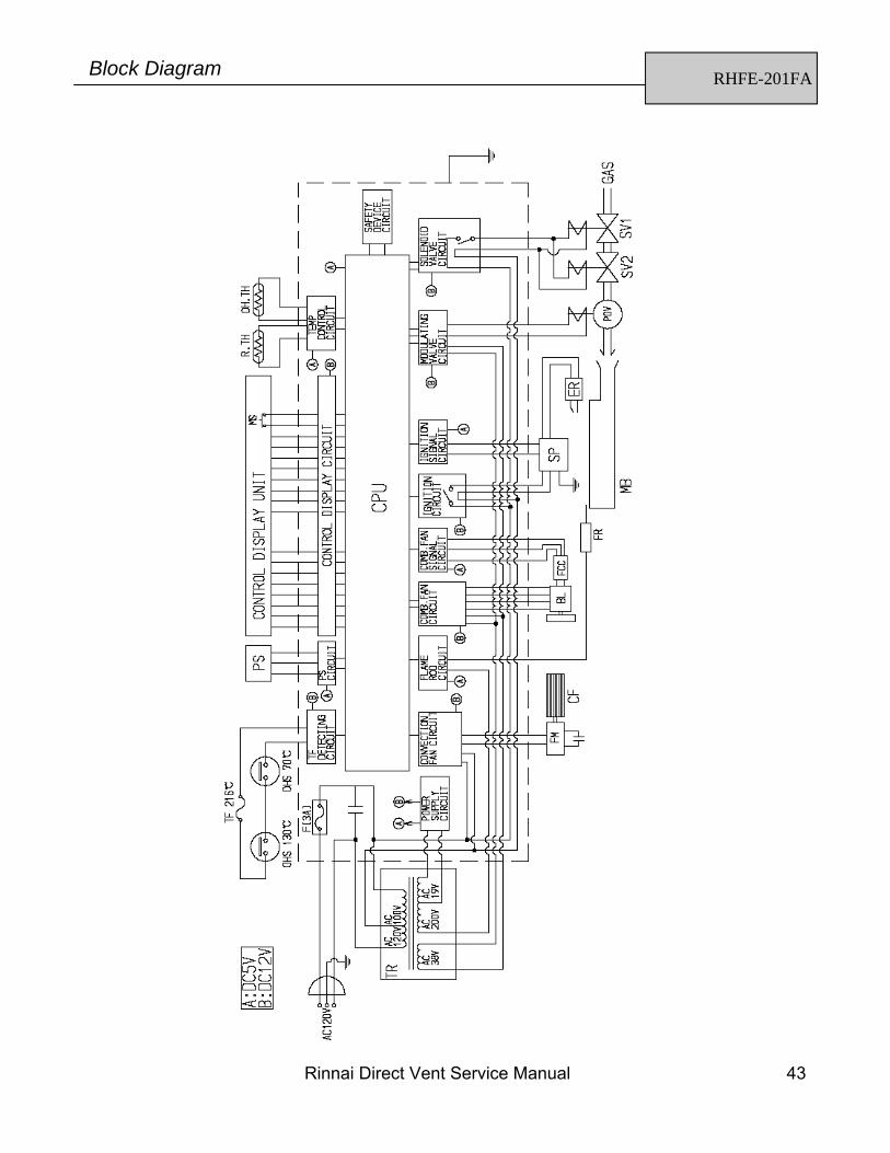
RHFE-201FA Block Diagram
44 Rinnai Direct Vent Service Manual
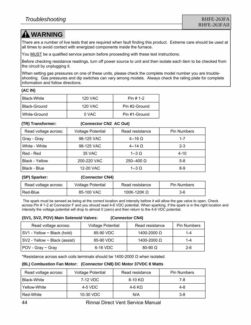
RHFE-263FA RHFE-263FAII
Troubleshooting
(AC IN)
Black-White 120 VAC Pin # 1-2
Black-Ground 120 VAC Pin #2-Ground
White-Ground 0 VAC Pin #1-Ground
(TR) Transformer: (Connector CN2 AC Out)
Read voltage across: Voltage Potential Read resistance Pin Numbers
Gray - Gray 98-125 VAC 4--16 Ω 1-7
Black - Yellow 200-220 VAC 250--400 Ω 5-8
Black - Blue 12-20 VAC 1--3 Ω 8-9
White - White 98-125 VAC 4--14 Ω 2-3
Red - Red 35 VAC 1--3 Ω 4-10
(SP) Sparker: (Connector CN4)
Read voltage across: Voltage Potential Read resistance Pin Numbers
Red-Blue 85-100 VAC 100K-120K Ω 3-6
The spark must be sensed as being at the correct location and intensity before it will allow the gas valve to open. Check across Pin # 1-2 at Connector F and you should read 4-6 VDC potential. When sparking, if the spark is in the right location and intensity the voltage potential will drop to almost 0 (zero) and then return to the 4-6 VDC potential.
(SV1, SV2, POV) Main Solenoid Valves: (Connector CN4)
Read voltage across: Voltage Potential Read resistance Pin Numbers
*Resistance across each coils terminals should be 1400-2000 Ω when isolated.
(BL) Combustion Fan Motor: (Connector CN8) DC Motor 37VDC 8 Watts
Read voltage across: Voltage Potential Read resistance Pin Numbers
Black-White 7-12 VDC 8-10 KΩ 7-8
Yellow-White 4-5 VDC 4-6 KΩ 4-8
Red-White 10-30 VDC N/A 3-8
WARNING There are a number of live tests that are required when fault finding this product. Extreme care should be used at all times to avoid contact with energized components inside the furnace.
You MUST be a qualified service person before proceeding with these test instructions.
Before checking resistance readings, turn off power source to unit and then isolate each item to be checked from the circuit by unplugging it.
When setting gas pressures on one of these units, please check the complete model number you are trouble-shooting. Gas pressures and dip switches can vary among models. Always check the rating plate for complete information and follow directions.
Rinnai Direct Vent Service Manual 45
RHFE-263FA RHFE-263FAII
Troubleshooting
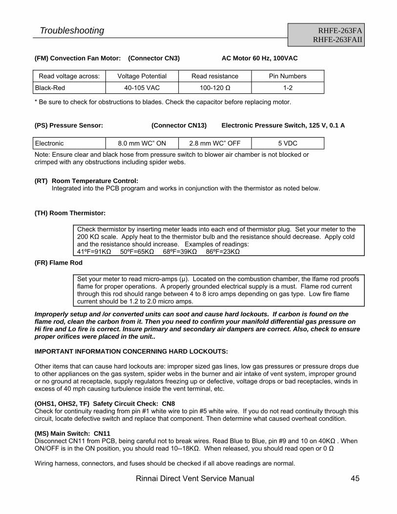
(FM) Convection Fan Motor: (Connector CN3) AC Motor 60 Hz, 100VAC
Read voltage across: Voltage Potential Read resistance Pin Numbers
Black-Red 40-105 VAC 100-120 Ω 1-2
* Be sure to check for obstructions to blades. Check the capacitor before replacing motor.
Note: Ensure clear and black hose from pressure switch to blower air chamber is not blocked or crimped with any obstructions including spider webs.
(TH) Room Thermistor:
Check thermistor by inserting meter leads into each end of thermistor plug. Set your meter to the 200 KΩ scale. Apply heat to the thermistor bulb and the resistance should decrease. Apply cold and the resistance should increase. Examples of readings: 41ºF=91KΩ 50ºF=65KΩ 68ºF=39KΩ 86ºF=23KΩ
(FR) Flame Rod
Set your meter to read micro-amps (µ). Located on the combustion chamber, the lfame rod proofs flame for proper operations. A properly grounded electrical supply is a must. Flame rod current through this rod should range between 4 to 8 icro amps depending on gas type. Low fire flame current should be 1.2 to 2.0 micro amps.
Improperly setup and /or converted units can soot and cause hard lockouts. If carbon is found on the flame rod, clean the carbon from it. Then you need to confirm your manifold differential gas pressure on Hi fire and Lo fire is correct. Insure primary and secondary air dampers are correct. Also, check to ensure proper orifices were placed in the unit.. IMPORTANT INFORMATION CONCERNING HARD LOCKOUTS: Other items that can cause hard lockouts are: improper sized gas lines, low gas pressures or pressure drops due to other appliances on the gas system, spider webs in the burner and air intake of vent system, improper ground or no ground at receptacle, supply regulators freezing up or defective, voltage drops or bad receptacles, winds in excess of 40 mph causing turbulence inside the vent terminal, etc. (OHS1, OHS2, TF) Safety Circuit Check: CN8 Check for continuity reading from pin #1 white wire to pin #5 white wire. If you do not read continuity through this circuit, locate defective switch and replace that component. Then determine what caused overheat condition. (MS) Main Switch: CN11 Disconnect CN11 from PCB, being careful not to break wires. Read Blue to Blue, pin #9 and 10 on 40KΩ . When ON/OFF is in the ON position, you should read 10--18KΩ. When released, you should read open or 0 Ω Wiring harness, connectors, and fuses should be checked if all above readings are normal.
(RT) Room Temperature Control: Integrated into the PCB program and works in conjunction with the thermistor as noted below.
46 Rinnai Direct Vent Service Manual
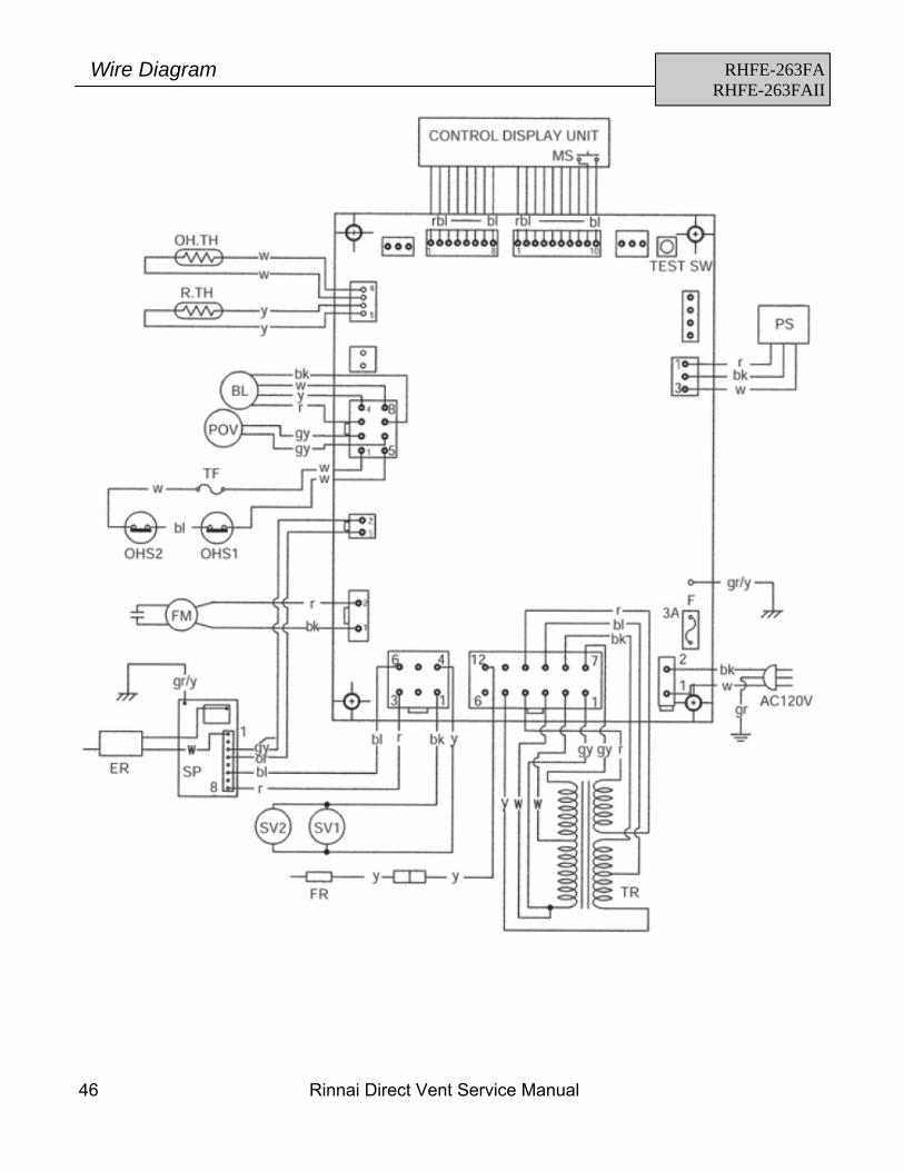
RHFE-263FA RHFE-263FAII
Wire Diagram
Rinnai Direct Vent Service Manual 47
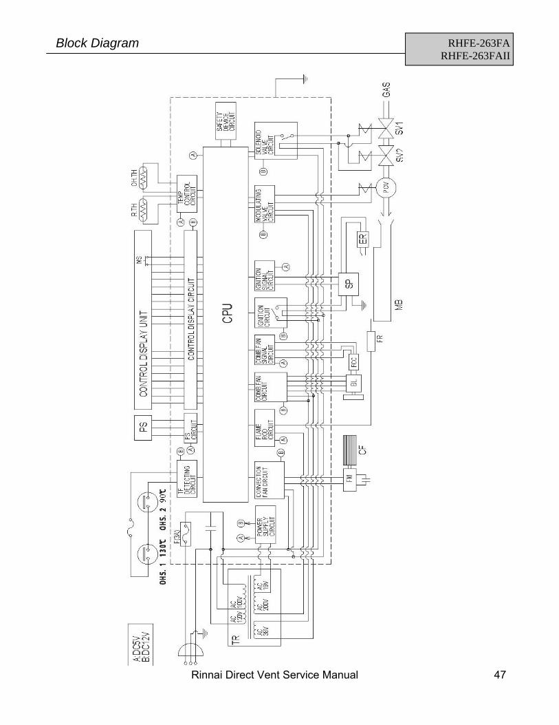
RHFE-263FA RHFE-263FAII
Block Diagram
48 Rinnai Direct Vent Service Manual
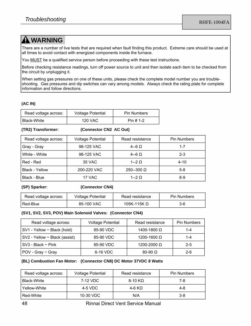
RHFE-1004FA Troubleshooting
(AC IN)
Read voltage across: Voltage Potential Pin Numbers
Black-White 120 VAC Pin # 1-2
(TR2) Transformer: (Connector CN2 AC Out)
Read voltage across: Voltage Potential Read resistance Pin Numbers
Gray - Gray 98-125 VAC 4--6 Ω 1-7
Black - Yellow 200-220 VAC 250--300 Ω 5-8
Black - Blue 17 VAC 1--2 Ω 8-9
White - White 98-125 VAC 4--6 Ω 2-3
Red - Red 35 VAC 1--2 Ω 4-10
(SP) Sparker: (Connector CN4)
Read voltage across: Voltage Potential Read resistance Pin Numbers
Red-Blue 85-100 VAC 105K-115K Ω 3-6
(SV1, SV2, SV3, POV) Main Solenoid Valves: (Connector CN4)
Read voltage across: Voltage Potential Read resistance Pin Numbers
(BL) Combustion Fan Motor: (Connector CN8) DC Motor 37VDC 8 Watts
Read voltage across: Voltage Potential Read resistance Pin Numbers
Black-White 7-12 VDC 8-10 KΩ 7-8
Yellow-White 4-5 VDC 4-6 KΩ 4-8
Red-White 10-30 VDC N/A 3-8
WARNING There are a number of live tests that are required when fault finding this product. Extreme care should be used at all times to avoid contact with energized components inside the furnace.
You MUST be a qualified service person before proceeding with these test instructions.
Before checking resistance readings, turn off power source to unit and then isolate each item to be checked from the circuit by unplugging it.
When setting gas pressures on one of these units, please check the complete model number you are trouble-shooting. Gas pressures and dip switches can vary among models. Always check the rating plate for complete information and follow directions.
Rinnai Direct Vent Service Manual 49
RHFE-1004FA Troubleshooting
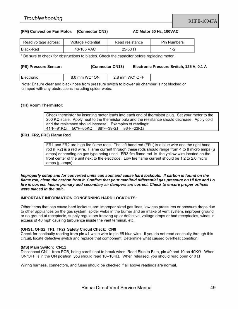
(FM) Convection Fan Motor: (Connector CN3) AC Motor 60 Hz, 100VAC
Read voltage across: Voltage Potential Read resistance Pin Numbers
Black-Red 40-105 VAC 25-50 Ω 1-2
* Be sure to check for obstructions to blades. Check the capacitor before replacing motor.
Note: Ensure clear and black hose from pressure switch to blower air chamber is not blocked or crimped with any obstructions including spider webs.
(TH) Room Thermistor:
Check thermistor by inserting meter leads into each end of thermistor plug. Set your meter to the 200 KΩ scale. Apply heat to the thermistor bulb and the resistance should decrease. Apply cold and the resistance should increase. Examples of readings: 41ºF=91KΩ 50ºF=65KΩ 68ºF=39KΩ 86ºF=23KΩ
(FR1, FR2, FR3) Flame Rod
FR1 and FR2 are high fire flame rods. The left hand rod (FR1) is a blue wire and the right hand rod (FR2) is a red wire. Flame current through these rods should range from 4 to 8 micro amps (µ amps) depending on gas type being used. FR3 fire flame rod is the yellow wire located on the front center of the unit next to the electrode. Low fire flame current should be 1.2 to 2.0 micro amps (µ amps).
Improperly setup and /or converted units can soot and cause hard lockouts. If carbon is found on the flame rod, clean the carbon from it. Confirm that your manifold differential gas pressure on Hi fire and Lo fire is correct. Insure primary and secondary air dampers are correct. Check to ensure proper orifices were placed in the unit.. IMPORTANT INFORMATION CONCERNING HARD LOCKOUTS: Other items that can cause hard lockouts are: improper sized gas lines, low gas pressures or pressure drops due to other appliances on the gas system, spider webs in the burner and air intake of vent system, improper ground or no ground at receptacle, supply regulators freezing up or defective, voltage drops or bad receptacles, winds in excess of 40 mph causing turbulence inside the vent terminal, etc. (OHS1, OHS2, TF1, TF2) Safety Circuit Check: CN8 Check for continuity reading from pin #1 white wire to pin #5 blue wire. If you do not read continuity through this circuit, locate defective switch and replace that component. Determine what caused overheat condition. (MS) Main Switch: CN11 Disconnect CN11 from PCB, being careful not to break wires. Read Blue to Blue, pin #9 and 10 on 40KΩ . When ON/OFF is in the ON position, you should read 10--18KΩ. When released, you should read open or 0 Ω Wiring harness, connectors, and fuses should be checked if all above readings are normal.
50 Rinnai Direct Vent Service Manual
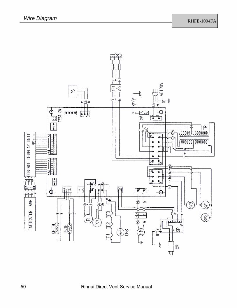
RHFE-1004FA Wire Diagram
Rinnai Direct Vent Service Manual 51
1. Check gas pressure at manifold, pressure should be:
2. Check air shutters adjustment: ___ RHFE1004FA set for propane should have no notches showing on adjustment rod. ___ RHFE1004FA set for natural: the right rear and left hand shutters should have no notches showing on
adjustment rod; the right front shutter should have 3 notches showing on the rod.
3. Ensure unit has the proper size orifices in it: ___Orifice sizes for the RHFE1004FA/VA on propane should be 0.95 mm (0.037”) on the back two burners and 1.20 mm (0.047”) on the front right burner. ___Orifices sizes for the RHFE1004FA/VA on natural should be 1.8 mm (0.071”) on the back two burners and
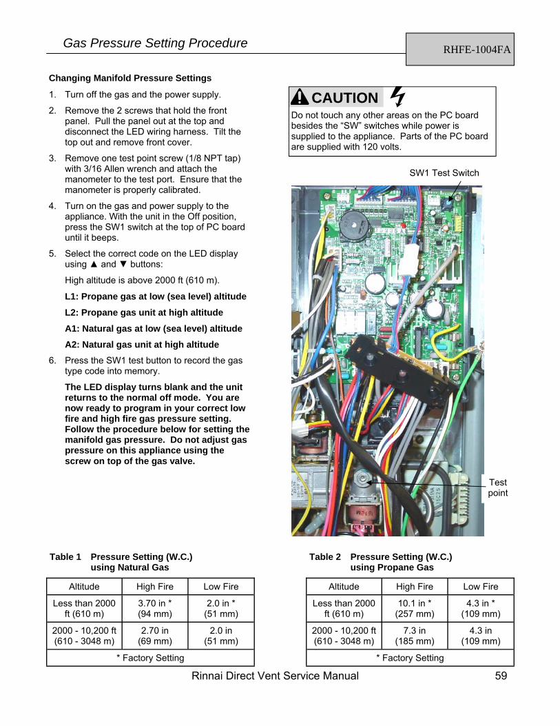
1.95 mm (0.077”) on the right front burner.
5. Inspect wall vent to ensure it is not clogged or restricted in any way. For proper inspection of combustion chamber air way, vent MUST be removed from wall.
6. Remove all flame rods and electrodes and inspect for cracks and/or carbon buildup. Clean flame rods and
electrode with some type of sandpaper.
7. Check all wire connections for loose or broken pins or connectors. Disconnect electrical power before performing this task.
8. Check resistance on all three gas valve solenoids. Unplug each coil before checking resistance. Set you meter
on the 2K scale, you should read between 1400 to 1800 ohms for SV1; 1200-1600 ohms for SV2; and 1200-2000 ohms for SV3. Power unit back up and set your meter to read 100 VDC scale, cycle unit and check voltage to each coil. You should read 85-90 VDC at each coil. If unit goes to lockout before you have time to read all coils, you may have to cycle it two or three times.
9. Ensure the air pressure switch is functioning properly. Ohm out the micro-switch located on the pressure
switch. Continuity will be read on meter when closed position.
10. Ensure the vent system does not exceed 13 feet total run, not exceeding 8 feet vertically, with no more than two bent elbows.
11. Check thermistor operation by inserting meter leads into each end of thermistor plug. Disconnect yellow to yellow from PCB, set your meter on the 200K scale. Your should be able to apply heat to the thermistor bulb and see resistances decrease. Place some ice on thermistor bulb and resistances should increase.
12. Check current on all flame rods: ___ FR1 and FR2 are high fire flame rods. The left hand rod (FR1) is a blue wire and the right hand rod
(FR2) is a red wire. Flame current through these rods should range from 4 to 8 micro amps (µ amps) depending on gas type being used. FR3 fire flame rod is the yellow wire located on the front center of the unit next to the electrode. Low fire flame current should be 1.2 to 2.0 micro amps (µ amps).
YOU MUST ENSURE UNIT IS GROUNDED !!
RHFE-1004FA Lock Out Checklist
Altitude Gas Type Manifold Differential Pressure
High (in W.C.) Low (in W.C.)
0-2000 ft (0-610 m) LPG / Propane
10.1 4.3
> 2000 ft (> 610 m) 7.3 4.3
0-2000 ft (0-610 m) 3.7 2.0
> 2000 ft (> 610 m) 2.7 2.0 Natural Gas
52 Rinnai Direct Vent Service Manual
DIRECT VENT EXTENSION INSTALLATION REQUIREMENTS
The purpose of these instructions is to explain the correct application of the vent extension sets for the Energy Saver direct vent furnaces. • Two elbows can be used. Do not count the elbow attached to the unit.
• The maximum total run is limited as follows:
• The maximum vertical rise is limited to 8 foot maximum on all units.
• EXAMPLE: If the vertical rise is 6.5 feet you can still run an additional 6.5 feet horizontal pitching the horizontal run 3º to the outside.
• Termination must always be horizontal.
• The vent pipe extension must not be concealed per NFPA 54 and must be accessible allowing inspection and repair. Decorative covers are available from Rinnai.
• The exhaust elbow assembly attached on the back of the unit SHALL NEVER be straightened.
• Do not shorten the intake air hose attached to unit from factory.
• Vent extensions ran in ANY unconditioned air space MUST be insulated with high temperature insulation and must be accessible.
• All pipe stoppers, connectors, screws, and hangars must be used as per the directions. The seals must be air tight for both the exhaust and the intake air supply hose.
• The intake air hose must equal the exhaust hose length to maintain a balanced flue system.
• The 431/556 Series units have a terminal block on the back that must be changed as per directions for any extension set. This terminal block is set for direct through the wall installation and must be changed if an extension set is used.
• The humidifier trays are made of enamel covered steel to resist rust and corrosion from the condensate draining back to the unit. The 201/263/431/556 series trays can be removed for cleaning but must be replaced before operation of the unit. The 1004FA tray can only be removed by a service technician.
• Over flow of the humidifier tray is an indication that the venting extension installation directions have not been followed and no warranty claim will be approved covering overflow.
Extension Installation Requirements
MODEL MAXIMUM TOTAL RUN
RHFE-551FA, RHFE-1001FA, RHFE-1001FA/VA 15 feet
RHFE-201FA, RHFE-263FA, FAII RHFE-431FA, FAII, FAIII, WTA RHFE-556FA, FAIII, FTRA, FTRAIII, WTA RHFE-1004FA
13 feet
Rinnai Direct Vent Service Manual 53
Vent Kits for the RHFE 201, 263, 431, 556, 1004 Series
KIT NO. NAME WALL THICKNESS
FOT-150 Vent Kit S 3” to 4-1/2“
FOT-151 Vent Kit A * 4-1/2” to 9-1/2”
FOT-152 Vent Kit B 9-1/2” to 15-3/4”
FOT-153 Vent Kit C 15-3/4” to 23-5/8”
FOT-154 Vent Kit D 23-5/8” to 31-1/2”
* Standard vent kit shipped with appliance.
The exhaust adaptor B assembly, P/N 1004F-530X01, is shipped with every 1004 appliance and must be in-stalled on the vent termination end every time, even when using extension sets. This allows the same vent termination kit to be used on all 1004FA models produced in 1999.
Vent Kits for the RHFE 1001FA Series
KIT NO. WALL THICKNESS
FOT-175 or 1001F-1670 3” to 4-1/2“
FOT-176 or 1001F-1671 4-1/2” to 9-1/2”
FOT-177 or 1001F-1672 9-1/2” to 15-3/4”
FOT-178 or 1001F-1673 15-3/4” to 23-5/8”
FOT-179 or 1001F-1674 23-5/8” to 31-1/2”
Vent Extensions for the RHFE 263, 431, 556 Series
KIT NO. NAME
FOT-155 Extension Set - 20”
FOT-156 Extension Set - 40”
FOT-157 Extension Set - 80”
FOT-158 * Elbow Set - 90 Degrees
FOT-190 Elbow Set - 90 Degrees - Long
Vent Extensions for the RHFE 1001 and 1004 Series
KIT NO. NAME
FOT-102 Extension Set - 20”
FOT-103 Extension Set - 40”
FOT-114 Extension Set - 80”
FOT-115 Elbow Set - 90 Degrees
* A maximum of one elbow (FOT-158) may be used on the RHFE-201FA to raise the flue manifold’s position by 6 in (154 mm) relative to the appliance.
Vent Kits and Extensions Sets
54 Rinnai Direct Vent Service Manual
Vent Extension Covers
KIT NO. NAME
FOT-132 Manifold Cover
FOT-133 Straight Cover
FOT-134 Elbow Cover
KIT NO. NAME
FOT-140 Manifold Cover
FOT-141 Straight Cover
FOT-142 Elbow Cover
FOT-162 Cover for First Piece on RHFE-1004FA *
Vent Extension Covers for the RHFE 263, 431, 556 Series
Vent Extension Covers for the RHFE 1001 and 1004 Series
Installations at Altitude Models RHFE-201FA, RHFE-263FA, RHFE-263FAII, RHFE-1004FA The PC boards of these models have altitude settings which allows operation up to 10,200 feet (3109 m). The correct altitude is entered using switches on the PC board and the appliance control buttons.
When installing these models, follow the Gas Pressure Setting Procedure for your model. This procedure adjusts the gas input pressure and the PC board settings.
When replacing a PC board, adjust the PC board settings according to the replacement part instructions.
Models RHFE-431FAIII, RHFE-431WTA, RHFE-556FAIII, RHFE-556FTRAIII, RHFE-556WTA For installations at altitude (greater than 2000 feet), follow the guidelines of the National Fuel Gas Code (NFPA 54) and all applicable local codes.
* This piece has a smaller cross section at one end to allow the filter to be removed for cleaning.
Rinnai Direct Vent Service Manual 55
RHFE-201FA, RHFE-263FA/FAII Gas Pressure Setting Procedure
1. Turn off the gas and the power supply.
2. Hold both ends of the bottom cover (undercover assembly) and pull toward you to remove the cover. Cover snaps in place.
3. Remove the 7 screws that hold the front panel and the louver assembly to remove panel from the unit. Pull the panel out at the bottom about 4 inches (100 mm) and lift up over clips that hold it in place at the unit’s top.
4. Remove two test point screws (1/8 NPT tap) with 3/16 Allen wrench and attach the manometer to both test ports. Both ports must be used in order to measure the differential pressure. Ensure that the manometer is properly calibrated.
5. Turn on the gas and power supply to the appliance. With the unit in the Off position, press the SW1 switch at the top of PC board until it beeps.
6. Select the correct code for gas type and altitude using and buttons:
Test points
CAUTION Do not touch any other areas on the PC board besides the “SW” switches while power is supplied to the appliance. Parts of the PC board are supplied with 120 volts AC.
NOTE: Some PC Boards (before version ED-263-V6-E4) will have only L1, L2, A1, and A2 codes. On these boards L2 and A2 are for altitudes above 2000 ft (610 m). See the figure to locate the label indicating the version.
L1: Propane gas below 2000 ft (610 m)
L2: Propane gas 2001-4500 ft (610-1372 m)
L3: Propane gas 4501-7800 ft (1372-2377 m)
L4: Propane gas 7801-10200 ft (2378-3109 m)
A1: Natural gas below 2000 ft (610 m)
A2: Natural gas 2001-4500 ft (610-1372 m)
A3: Natural gas 4501-7800 ft (1372-2377 m)
A4: Natural gas 7801-10200 ft (2378-3109 m)
Model Altitude Gas Type High Fire Low Fire
201FA
0 - 10,200 ft
(610 - 3109 m)
Natural Gas
3.3 in (85 mm)
0.6 in (16 mm)
Propane 6.0 in (152 mm)
0.9 in (24 mm)
Model Altitude Gas Type High Fire Low Fire
Less than
2000 ft (610 m)
Natural Gas
2.3 in (58 mm)
0.6 in (16 mm)
Propane 3.7 in (94 mm)
1.1 in (27 mm)
2000 - 10,200 ft
(610 - 3109 m)
Natural Gas
1.7 in (42 mm)
0.6 in (16 mm)
Propane 2.7 in (68 mm)
1.1 in (27 mm)
263FA
263FAII
SW1
PC Board Version Label
56 Rinnai Direct Vent Service Manual
RHFE-201FA, RHFE-263FA/FAII Gas Pressure Setting Procedure
7. Press the SW1 test button to record the gas type code into memory. The LED will display “F1”. If not shown, use the and buttons to obtain “F1”.
8. Press the SW1 switch to enter this code into memory.
9. The LED will display the temperature scale. Use the and buttons to select the Fahrenheit or Celsius scale.
10. Press the SW1 switch for more than 2 seconds to enter the temperature scale into memory.
The LED display turns blank and the unit returns to the normal off mode. While programming the correct low fire and high fire gas pressure settings, do not adjust gas pressure on this appliance using the screw on top of the gas valve.
11. Press the ON/OFF button to operate the appliance.
12. Press the SW1 switch. The LED will display “78”.
13. Press the SW1 switch again to change to the low pressure mode. The LED will display “PL”.
14. Compare the pressure reading on the manometer to the desired manifold test pressure (low) for your gas type and altitude. If necessary adjust the low fire pressure using the and buttons. Press the SW1 switch to record into memory.
15. The LED will display “PH” indicating high fire mode.
16. Compare the pressure reading on the manometer to the desired manifold test pressure (high) for your gas type and altitude. If necessary adjust the high fire pressure using the and buttons. Press the SW1 switch to record into memory.
17. Press the SW1 switch 2 times. After pushing the SW1 switch 2 times, the LED display will display “78”. If the LED shows any thing other than “78” call Rinnai Technical Support at 1-800-621-9419 for assistance.
18. Press the ON/OFF button again. The LED display turns blank and the appliance returns to the normal OFF mode.
Check that the burner flames are operating normally. The flame can be seen through the circular window through the louvers.
When operating normally the burner flame should appear as long, clear, blue, stable, streaks. Yellow flames or an orange color is abnormal and maintenance is required.
Visual Inspection of Flame CAUTION Do not touch the areas at or near the exhaust. These areas become very hot and could cause burns.
NORMAL
Flame Rod
Long, clear, blue, stable flames
ABNORMAL
Yellow flames or orange color
Flame Rod
Install the front panel and bottom cover. Final Assembly
•check the normal operating sequence •visually inspect the flame •check for gas leaks at the test points
Normal Operating Sequence When you press the ON/OFF button, the LED display will illuminate, the combustion fan will begin to run, and the spark will ignite the main burner.
This heater has an automatic ignition system. When the main burner has lit, the combustion lamp will glow red, and the spark will stop.
19. Remove manometer and install Allen head screws. Operate the unit and
Rinnai Direct Vent Service Manual 57
RHFE-431 Series, RHFE-556 Series Gas Pressure Setting Procedure
1. There are two test points, one on the manifold and one on the gas control assembly. Connect the pres-sure gauge to both test points. Using an electronic manometer, connect the negative side to the manifold test point.
2. Press the ON/OFF switch. After unit ignites, wait ap-proximately one minute.
3. Press the (SW5) button to start the programming mode.
4. Press the (SW4) button. Use the arrow buttons to set the low pressure to the appropriate setting for your model and gas type. The V button will decrease the pressure each time the button is pushed. The W but-ton increases the pressure each time it is pushed.
5. Press the (SW4) button to lock in the low pressure.
6. Press the (SW3) button. Use the arrow buttons to set the high pressure to the appropriate setting for your model and gas type. The button will decrease the pressure each time the button is pushed. The but-ton increases the pressure each time it is pushed.
7. Press the (SW3) button to lock in the high pressure.
8. Press the (SW5) button to exit the programming mode and return the appliance to its normal operating mode.
9. Press the ON/OFF button to turn the appliance off.
10. Remove manometer and install the test point screws. Operate the unit and
Normal Operating Sequence When you press the ON/OFF button, the LED display will illuminate, the combustion fan will begin to run, and the spark will ignite the main burner.
This heater has an automatic ignition system. When the main burner has lit, the combustion lamp will glow red, and the spark will stop.
•check the normal operating sequence •visually inspect the flame •check for gas leaks at the test points
Nozzle Manifold
PressurePoint1
PressurePoint2
Gas ValveAdjustment screw
CAUTION Do not touch any other areas on the PC board besides the “SW” switches while power is supplied to the appliance. Parts of the PC board are supplied with 120 volts.
CAUTION Do not touch the areas at or near the heat exchanger or burner. These areas become very hot and could cause burns.
SW6 SW3SW4
SW5
58 Rinnai Direct Vent Service Manual
RHFE-431 Series, RHFE-556 Series Gas Pressure Setting Procedure
Check that the burner flames are operating normally. The flame can be seen through the circular window through the louvers.
When operating normally the burner flame should appear as long, clear, blue, stable, streaks. Yellow flames or an orange color is abnormal and maintenance is required.
Visual Inspection of Flame
Install the front panel and bottom cover. Final Assembly
NORMAL
Flame Rod
Long, clear, blue, stable flames
ABNORMAL
Yellow flames or orange color
Flame Rod
Model Gas Type High Fire Low Fire
431 Series * Natural Gas 2.4 in
(61 mm) 0.7 in
(18 mm)
Propane 2.8 in (71 mm)
0.8 in (20 mm)
Natural Gas 3.8 in (97 mm)
0.7 in (18 mm)
Propane 4.5 in (114 mm)
0.8 in (20 mm)
556 Series *
* For installations at altitude (greater than 2000 feet), follow the guidelines of the National Fuel Gas Code (NFPA 54) and all appli-cable local codes.
Rinnai Direct Vent Service Manual 59
RHFE-1004FA Gas Pressure Setting Procedure
Changing Manifold Pressure Settings
1. Turn off the gas and the power supply.
2. Remove the 2 screws that hold the front panel. Pull the panel out at the top and disconnect the LED wiring harness. Tilt the top out and remove front cover.
3. Remove one test point screw (1/8 NPT tap) with 3/16 Allen wrench and attach the manometer to the test port. Ensure that the manometer is properly calibrated.
4. Turn on the gas and power supply to the appliance. With the unit in the Off position, press the SW1 switch at the top of PC board until it beeps.
5. Select the correct code on the LED display using and buttons:
High altitude is above 2000 ft (610 m).
L1: Propane gas at low (sea level) altitude
L2: Propane gas unit at high altitude
A1: Natural gas at low (sea level) altitude
A2: Natural gas unit at high altitude 6. Press the SW1 test button to record the gas
type code into memory.
The LED display turns blank and the unit returns to the normal off mode. You are now ready to program in your correct low fire and high fire gas pressure setting. Follow the procedure below for setting the manifold gas pressure. Do not adjust gas pressure on this appliance using the screw on top of the gas valve.
Test point
SW1 Test Switch
CAUTION Do not touch any other areas on the PC board besides the “SW” switches while power is supplied to the appliance. Parts of the PC board are supplied with 120 volts.
Altitude High Fire Low Fire
Less than 2000 ft (610 m)
10.1 in * (257 mm)
4.3 in * (109 mm)
2000 - 10,200 ft (610 - 3048 m)
7.3 in (185 mm)
4.3 in (109 mm)
* Factory Setting
Table 2 Pressure Setting (W.C.) using Propane Gas
Altitude High Fire Low Fire
Less than 2000 ft (610 m)
3.70 in * (94 mm)
2.0 in * (51 mm)
2000 - 10,200 ft (610 - 3048 m)
2.70 in (69 mm)
2.0 in (51 mm)
* Factory Setting
Table 1 Pressure Setting (W.C.) using Natural Gas
60 Rinnai Direct Vent Service Manual
RHFE-1004FA Gas Pressure Setting Procedure
7. Press the ON/OFF button to operate the appliance.
8. Press the SW1 switch. The LED will display “78” or “7 ”.
9. Press the SW1 switch again to change to the low pressure mode. The LED will display “PL”.
10. Compare the pressure reading on the manometer to the correct table for your gas type. If necessary adjust the low fire pressure using the and buttons.
11. Press the Economy button. The LED will display “18” indicating that the low pressure has been recorded into memory.
12. Press the SW1 switch TWICE. This puts the appliance into the high fire mode. The LED will display “PH”.
13. Compare the pressure reading on the manometer to the correct table for your gas type. If necessary adjust the high fire pressure using the and buttons.
14. Press the Economy button to enter the high fire pressure into memory. The LED display will display “78”. If the LED shows any thing other than “78” call Rinnai Technical Support at 1-800-621-9419 for assistance.
15. Press the ON/OFF button again. The LED display turns blank and the appliance returns to the normal OFF mode.
17. Remove manometer and install Allen head screws. Operate the unit and
CAUTION Do not insert hands or objects into the circulation fans while they are running. Injury or mechanical malfunction may occur.
CAUTION Do not touch the areas at or near the heat exchanger or burner. These areas become very hot and could cause burns.
Check that the burner flames are operating normally. The flame can be seen through the circular window through the louvers.
When operating normally the burner flame should appear as long, clear, blue, stable, streaks. Yellow flames or an orange color is abnormal and maintenance is required.
Visual Inspection of Flame
Install the front panel and bottom cover. Final Assembly
Normal Operating Sequence When you press the ON/OFF button, the LED display will illuminate, the combustion fan will begin to run, and the spark will ignite the main burner.
This heater has an automatic ignition system. When the main burner has lit, the combustion lamp will glow red, and the spark will stop.
•check the normal operating sequence •visually inspect the flame •check for gas leaks at the test points
Rinnai Direct Vent Service Manual 61
Dip Switch Settings
ON
OFF
PROPANE
ON
OFF
NATURAL GAS
RHFE-556WTA
ON
OFF
PROPANE
ON
OFF
NATURAL GAS
RHFE-556FA / FTRA Series
ON
OFF
PROPANE
ON
OFF
NATURAL GAS
RHFE-431WTA
ON
OFF
PROPANE
ON
OFF
NATURAL GAS
RHFE-431FA Series
The other models (RHFE-201FA, RHFE-263FA Series, RHFE-551FA, RHFE-1001 Series, and RHFE-1004FA) do not have dip switches.
62 Rinnai Direct Vent Service Manual
Checking Micro-amps RHFE 201, 263, 431, 556 Series
1. Locate the yellow wire from the flame rod. Disconnect at Molex.
2. Set the meter to read micro-amps.
3. Place the meter in series with the flame rod a the disconnected Molex.
4. Operate the appliance and view the flame development in the view window.
5. Read the micro-amps on the meter for high fire and low fire conditions.
NOTE: Volt meters differ in style and configuration. It is the technician’s responsibility to know the tools and how to set up for operations and testing.
Rinnai Direct Vent Service Manual 63
Setting up the U Tube Manometer RHFE 201, 263, 431, 556 Series
• The zero point is marked on the manometer.
• To read the differential pressure, add from zero upward and from zero downward.
• Differential pressures must be re-set if the PC board or gas control valve is replaced, or if the appliance is converted for gas type.
ONE HOSE FROM U-TUBE TO PRESSURE PORT ON BURNER MANIFOLD 1/8 NPT TAP
ONE HOSE FROM U-TUBE TO PRESSURE PORT ON GAS CONTROL VALVE 1/8 NPT TAP
64 Rinnai Direct Vent Service Manual
Thermistor The thermistor is a semiconductor which reacts to changes in the temperature by altering it resistance. The relationship between the temperature and the resistance is outlined in the graph. The resistance value is detected electronically, and activates the amplification circuit, which in turn operates the gas input control circuit (temperature control).
Flame Rectification Flame rectification is utilized to check flame presence. A flame sensing electrode consisting of a stainless steel rod supported in a ceramic insulator (flame rod) is positioned above the main burner. An alternating current is applied to the flame rod by the flame guard amplifier. The body of the burner and the flame guard amplifier (FGA) are both grounded.
The principle of flame rectification relies on the ability of the flame to conduct positively charged ions more easily than negatively charged ions. This characteristic is called flame rectification, as the current leaving the burner, having passed through the flame, is no longer an alternating current. The signal returning to the FGA has been rectified by the flame, and is used to determine flame presence.
The signal can only be produced by the flame. Short circuits, dirty contacts and other fault situations cannot simulate the rectified signal. The FGA section of the PC board sends an amplified signal to the main PC board to indicate flame presence, allowing the gas valves to remain open.
Temperature
Resistance
Resistance decreases asthe temperature increases.
Flame Rod Alternation currentAC 200 volts
Direction ofAC current C
heck
Am
plify
Flame Guard AmplifierMain Burner
SolenoidPC Board Gas Valve Circuit
1. Plug unit up to the power supply circuit.
2. Now with the unit in the “Off” mode press the “UP” button first and then press the “Test Switch”. This will enter the unit into the programming mode.
3. To begin programming your desired temperature limit set point, press the “Up” or “Down” temperature adjustment button on the control panel until you have achieved your set point. Once you have select your maximum temperature set point, press the “Test Switch” once, this locks in your maximum operating temperature at the temperature you selected.
Temperature set point limits are - (H) high fire, 80, 78, 76, 74, 72, 70. The unit will limit its operating temperature to one of the set points above, based on your selection.
Setting a Maximum Temperature RHFE-263FA/FAII, RHFE431WTA, RHFE-556WTA, RHFE-1004FA
Rinnai Direct Vent Service Manual 65
CODE COLOR
bk black
bl blue
br brown
gr green
pl purple
r red
w white
y yellow
gy gray
or orange
MARK PART NAME
MS MAIN SWITCH
R.TH THERMISTOR
TF THERMAL FUSE
F FUSE
ER ELECTRODE
POV MODULATING SOLENOID VALVE
TR TRANSFORMER
FR FLAME ROD
OH. TH OVER HEAT THERMISTOR
OHS OVER HEAT SWITCH
FM CONVECTION FAN MOTOR
SP SPARKER
SV SOLENOID VALVE
BL COMUSTION FAN MOTOR
RCR REMOTE CONTROL RECEIVER
TB TERMINAL BLOCK
CF CONVECTION FAN
FCC FAN CONTROL CIRCUIT
CPU CENTRAL PROCESSING UNIT
MB MAIN BURNER
PS PRESSURE SENSOR
RHFE-1004FA (using propane) Harmonic Noise
On occasion, a whistling noise may come from the RHFE-1004FA using propane gas. This harmonic noise can be attributed to varying gas compositions and is more prevalent on new tank sets that may still have high traces of methanol in the system. The adjustments recommended are not detrimental to the operation of the appliance in any way.
PROCEDURE:
1. Perform the Gas Pressure Setting Procedure. During this procedure, set the low fire manifold gas pressure to 3.9” W.C. and the high fire manifold gas pressure to 9.8” W.C.
2. After performing the above procedure, set the low fire burner air shutter to three notches. This adjustment rod can be found on the right hand front burner just under the gas line where it enters the combustion chamber. Loosen the set screw in the brass slide and slide the shutter rod out to the third notch.
Wire Diagram Abbreviations
66 Rinnai Direct Vent Service Manual
1. With the appliance unplugged (electrical power source disconnected), disconnect both air pressure hoses from the right side of the appliance. Install the new PC board. After installing the PC board, re-apply the power to the appliance.
2. Turn on the gas and power supply to the appliance. With the unit in the Off position, press the SW1 switch at the top of PC board until it beeps.
3. Select the correct code for your model, gas type, and altitude using and buttons:
RHFE-201FA, RHFE-263FA / FAII
L1: Propane gas below 2000 ft (610 m)
L2: Propane gas 2001-4500 ft (610-1372 m)
L3: Propane gas 4501-7800 ft (1372-2377 m)
L4: Propane gas 7801-10200 ft (2378-3109 m)
A1: Natural gas below 2000 ft (610 m)
A2: Natural gas 2001-4500 ft (610-1372 m)
A3: Natural gas 4501-7800 ft (1372-2377 m)
A4: Natural gas 7801-10200 ft (2378-3109 m)
RHFE-1004FA
High altitude is above 2000 ft (610 m).
L1: Propane gas at low (sea level) altitude
L2: Propane gas unit at high altitude
A1: Natural gas at low (sea level) altitude
A2: Natural gas unit at high altitude
RHFE-201FA RHFE-263FA/FAII RHFE-1004FA
Removal of “OF” on New PC Board Installation
4. Press the SW1 test button to record the gas type code into memory. The LED will display “F1”. If not shown, use the and buttons to obtain “F1”.
5. Press the Test button to enter this code into memory.
6. The LED will display the temperature scale. Use the and buttons to select the Fahrenheit or Celsius scale.
7. Press the Economy button for more than 2 seconds to enter the temperature scale into memory.
The LED display turns blank and the unit returns to the normal off mode. Reinstall the air pressure hoses before turning the unit to the ON position. Program the correct low fire and high fire gas pressure settings. Do not adjust gas pressure on this appliance using the screw on top of the gas valve.
4. Press the Economy button to record the gas type code into memory.
The LED display turns blank and the unit returns to the normal off mode. Reinstall the air pressure hoses before turning the unit to the ON position. Program the correct low fire and high fire gas pressure settings. Do not adjust gas pressure on this appliance using the screw on top of the gas valve.
RHFE-201FA, RHFE-263FA / FAII RHFE-1004FA
Rinnai Direct Vent Service Manual 67
Notes
Rinnai’s other fine products Rinnai America Corporation 103 International Drive
Peachtree City, GA 30269 TOLL FREE: 1-800-621-9419
Direct Vent Furnaces • High Efficiency • Cool-to-the-touch Cabinet • Blower Included • Vent Terminal A Included • 556 and 1004 Models Available in Beige, White and Silver • Gas Conversion Kit Included
Hydronic Air Handler • Designed for Use with Rinnai Systems • Domestic Hot Water Priority • Optional Programmable Thermostat • Zero Clearance to Combustibles • Accommodates Standard Cased-Coils
Direct-Vent Fireplace, RHFE-750ETR • Up to 83% AFUE Energy Efficiency • Zero-Clearance Installation • Available in Four Options of Fronts • Remotes and Fan Included • Gas Conversion Kit Available
Tankless Water Heaters • Residential and Commercial Applications • Continuous Hot Water • Up to 9.8 GPM • High Energy Efficiency • Propane or Natural Gas • Internal or External Installation • Digital Temperature Control • Small, Compact Design
Register your product at www.rinnairegistration.com or call 1-866-RINNAI1 (746-6241)