Proceedings of the 2001 American Society for Engineering Education Annual Conference & Exposition Copyright 2001, American Society for Engineering Education The Sophomore Engineering Clinic I: Integrating Statics, Solid Mechanics and Product Development in a Sophomore Level Design Course Anthony J. Marchese, Eric Constans, Kevin Dahm, Kathryn Hollar, David Hutto, Frances Johnson, Carlos Sun and Paris von Lockette, Jennifer Kadlowec Doug Cleary and Beena Sukumaran College of Engineering Rowan University 201 Mullica Hill Rd. Glassboro, NJ 08028-1701 Abstract - The Engineering Clinic is a design course that is taken every semester by every engineering student in the College of Engineering at Rowan University. A major objective of the Sophomore Engineering Clinic I (the third course in the 8-semester sequence) is to provide the foundation necessary for students to become creative and effective engineering designers. This objective is accomplished by requiring all students to complete a semester long design and development project. During the Fall 2000 semester, the semester-long project was to design and develop a portable bridge for domestic use that would enable a homeowner to cross a typical backyard brook or stream with their riding lawn mower. The portable bridge was intended to be marketed directly to the homeowner via a retail outlet (e.g. The Home Depot) and needed to be easily assembled by the consumer and adaptable to various sized spans. During the first half of the semester, students were divided into 27 separate conceptual design teams of four students each and given 5 weeks to develop and document their conceptual and configuration designs. At the midpoint of the semester, three proposals were chosen for full-scale prototype development. During the second half of the semester, students were reassigned to a product development team, which had a specific task to complete in support of the full-scale development of one of the three chosen bridge products. A major reason for the success of the bridge project was that it reinforced the engineering science principles that were being taught concurrently in the more traditional engineering courses. For example, using principles from Statics and Solid Mechanics, each team analyzed the stresses in each two-force member and calculated the deflection due to bending of various components. Student surveys suggest that the bridge project helped students to better understand the engineering principles that were taught concurrently in their supporting coursework. Furthermore, the surveys suggest that students actually applied those principles to the design and development of an engineered product. Introduction The College of Engineering at Rowan University is composed of four departments: Chemical Engineering; Civil and Environmental Engineering; Electrical and Computer Engineering; and Mechanical Engineering. Each department has been designed to serve 25 to 30 students per year, resulting in 100 to 120 students per year in the College of Engineering. The size of the program has been optimized such that it is large enough to provide specialization in separate and credible departments, yet small enough to deliver a truly multidisciplinary curriculum in which laboratory/design courses are offered simultaneously to all engineering students in all four Session 2425
Transcript
Proceedings of the 2001 American Society for Engineering Education Annual Conference & E Copyright 2001, American Society for Engineering Education
The Sophomore Engineering Clinic I: Integrating Statics, Soland Product Development in a Sophomore Level Design
Anthony J. Marchese, Eric Constans, Kevin Dahm, Kathryn Hollar,
Frances Johnson, Carlos Sun and Paris von Lockette, Jennifer KDoug Cleary and Beena Sukumaran
College of Engineering
Rowan University 201 Mullica Hill Rd.
Glassboro, NJ 08028-1701
Abstract - The Engineering Clinic is a design course that is taken every engineering student in the College of Engineering at Rowan University. A maSophomore Engineering Clinic I (the third course in the 8-semester sequencefoundation necessary for students to become creative and effective engineerinobjective is accomplished by requiring all students to complete a semestedevelopment project. During the Fall 2000 semester, the semester-long proand develop a portable bridge for domestic use that would enable a homeownebackyard brook or stream with their riding lawn mower. The portable bridge marketed directly to the homeowner via a retail outlet (e.g. The Home Depoteasily assembled by the consumer and adaptable to various sized spans. Durithe semester, students were divided into 27 separate conceptual design teameach and given 5 weeks to develop and document their conceptual and configuthe midpoint of the semester, three proposals were chosen for full-scale protoDuring the second half of the semester, students were reassigned to a product which had a specific task to complete in support of the full-scale developmentchosen bridge products. A major reason for the success of the bridge preinforced the engineering science principles that were being taught concurtraditional engineering courses. For example, using principles from Mechanics, each team analyzed the stresses in each two-force member adeflection due to bending of various components. Student surveys suggest thahelped students to better understand the engineering principles that were taugtheir supporting coursework. Furthermore, the surveys suggest that studenthose principles to the design and development of an engineered product.
Introduction The College of Engineering at Rowan University is composed of four depaEngineering; Civil and Environmental Engineering; Electrical and ComputeMechanical Engineering. Each department has been designed to serve 25 to 30resulting in 100 to 120 students per year in the College of Engineering. The shas been optimized such that it is large enough to provide specialization in sedepartments, yet small enough to deliver a truly multidisciplinary curlaboratory/design courses are offered simultaneously to all engineering st
Session 2425
xposition
id Mechanics Course
David Hutto, adlowec
semester by every jor objective of the ) is to provide the g designers. This
r long design and ject was to design r to cross a typical was intended to be ) and needed to be ng the first half of s of four students ration designs. At type development. development team, of one of the three roject was that it rently in the more Statics and Solid nd calculated the
t the bridge project ht concurrently in
ts actually applied
rtments: Chemical r Engineering; and students per year, ize of the program parate and credible riculum in which udents in all four
Proceedings of the 2001 American Society for Engineering Education Annual Conference & Exposition Copyright 2001, American Society for Engineering Education
disciplines. Indeed, the hallmark of the engineering program at Rowan University is the multidisciplinary, project-oriented Engineering Clinic sequence.
The Engineering Clinic is a course that is taken each semester by every engineering student at Rowan University. In the Engineering Clinic, which is based on the medical school model, students and faculty from all four engineering departments work side-by-side on laboratory experiments, design projects and research. The solution of these real-world problems require not only a proficiency in the technical principles, but, as importantly, require a mastery of written and oral communication skills and the ability to work as part of an multidisciplinary team1,2. Table 1 contains an overview of course content in the 8-semester engineering clinic sequence. As shown in the table, while each clinic course has a specific theme, the underlying concept of engineering design permeates throughout 3.
Table 1. Overview of course content in the 8-semester Engineering Clinic sequence.
This 4-year, 20-credit design sequence offers students the opportunity to incrementally learn the science and art of design by continuously applying the technical skills they have obtained in traditional coursework. And, by applying this just-in-time approach to engineering design education it is possible for students to complete ambitious design projects as early as the sophomore year. This paper describes a product design and development project that was completed in Fall 2000 within the Sophomore Engineering Clinic I. The project, which was completed by 108 students from each of the four engineering departments, consisted of the design and development of a portable, residential bridge that could be purchased by a consumer at a retail outlet.
Sophomore Engineering Clinic I The two main goals of the Sophomore Engineering Clinic I (the third course in the 8-semester Engineering Clinic sequence) are to provide the foundation necessary for students to become:
• creative engineering designers, and
• effective engineering communicators. To satisfy these two goals, each student completes a semester-long design project. To successfully complete the course, each student must produce 5 technical communication deliverables along with the final engineering prototype.
The above goals are accomplished by introducing students to a Total Quality Management (TQM) approach to design and technical communication4,5. Using this approach, multidisciplinary student teams organize engineering specifications using the House of Quality6,
Proceedings of the 2001 American Society for Engineering Education Annual Conference & Exposition Copyright 2001, American Society for Engineering Education
develop several conceptual designs using various brainstorming techniques, evaluate these designs using Pugh’s method7, and perform guided iteration to identify optimum designs. Finally, they build, instrument and test a fully functional prototype.
During the Fall 2000 semester, the semester project was to design and develop a portable bridge for domestic use that would enable a homeowner to cross a typical backyard brook or stream with their riding lawn mower. The portable bridge, which was intended to be marketed directly to the homeowner via a retail outlet (e.g. The Home Depot), needed to be easily assembled by the consumer and adaptable to various sized spans.
The portable bridge design project was chosen primarily because of its potential for close integration with the supporting engineering courses. Developing realistic design projects in the freshman and sophomore year is always a challenge insofar as students lack the necessary background to perform significant engineering analyses. On the other hand, if students are required to wait until their senior year to attempt an open-ended design project, the engineering tools they obtain in the sophomore and junior year are largely forgotten before they can be applied to a real design problem. In this regard, the portable bridge design is ideal for the sophomore level. Physics, Calculus and some basic Statics and Solid Mechanics were the only areas of study that were to necessary to complete the required engineering analyses for this project, particularly for the conceptual design phase. As shown in table 2, all students had taken Physics and Calculus, while 75% of students were concurrently enrolled in Statics and 50% of students were concurrently enrolled in Solid Mechanics.
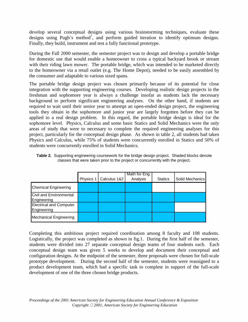
Table 2. Supporting engineering coursework for the bridge design project. Shaded blocks denote classes that were taken prior to the project or concurrently with the project.
Completing this ambitious project required coordination among 8 faculty and 108 students. Logistically, the project was completed as shown in fig.1. During the first half of the semester, students were divided into 27 separate conceptual design teams of four students each. Each conceptual design team was given 5 weeks to develop and document their conceptual and configuration designs. At the midpoint of the semester, three proposals were chosen for full-scale prototype development. During the second half of the semester, students were reassigned to a product development team, which had a specific task to complete in support of the full-scale development of one of the three chosen bridge products.
Physics 1 Calculus 1&2Math for Eng.
Analysis Statics Solid Mechanics
Chemical Engineering Civil and Environmental EngineeringElectrical and Computer Engineering
Mechanical Engineering
Proceedings of the 2001 American Society for Engineering Education Annual Conference & Exposition Copyright 2001, American Society for Engineering Education
108 Students
ConceptualDesign Team 1
(4 students)
Team 2 Team N Team 27
Select winning bridges
Company 1
Company 2 (33 Students)
Company 3
Marketing/Web Design/CAD
Economics Environmental/Legal
Structural Analysis Prototyping
Product Testing
Report,Prototypes, Competition
Week 2
Week 7
Bridge Project Assigned
Week 15 Figure 1. Logistics required for completing the bridge design project.
Conceptual Design Teams After a brief introduction to engineering design and quality issues, the portable bridge design project was assigned during the third week of class. During the third week, the students were divided into 27 separate conceptual design teams of four students each. Each conceptual design team began the project by identifying the customer attributes (CA's) associated with a "quality" portable bridge. Next, they used the House of Quality to map the vague, non-technical customer attributes into real engineering characteristics (EC's). They then began brainstorming and developing as many design alternatives as possible.
Proceedings of the 2001 American Society for Engineering Education Annual Conference & Exposition Copyright 2001, American Society for Engineering Education
Each conceptual design team was given 5 weeks to develop their conceptual design and document their design in the form of a 20-page proposal written jointly to the engineering faculty members and technical writing instructors. Each proposal had to detail the process by which they chose their final conceptual design and present a detailed analysis of that design.
Since most students were concurrently enrolled in Statics and Solid Mechanics and all students had taken Physics I (which also includes an introduction to Statics), the analysis of their conceptual design was possible. For example, using principles from Statics and Solid Mechanics, each team analyzed the stresses in each two-force member and calculated the deflection due to bending of various components.
To assist students in performing these calculations, tutorials were provided via the Internet. These tutorials included examples from Statics and Solid Mechanics as well as definitions and material properties. Also, to reinforce the integration between the design project and the concurrent engineering courses, instructors from each of the Statics and Solid Mechanics courses performed guest lectures in the clinic laboratory sections and continuously referred to the design project within their own lectures. Furthermore, the software program WinTruss, which was introduced in the Statics course as a means of calculating force, stress and deflection of 2-D truss networks, was used in both Statics and the Clinic course.
Product Development Teams During the 7th week of class, the entire group of students developed the criteria by which the top conceptual designs would be judged. The entire class then used Pugh’s method to choose the top three bridges. The 108 students were then divided into 3 companies, each of which was tasked with performing parametric design, developing a full-scale prototype and writing a final report to a potential investor. Clearly, there was much work to be done with only 8 weeks remaining in the semester. To perform the required tasks, each of the three companies was divided into the 7 following product development teams:
• Marketing/Web
• Economic Feasibility
• Environmental and Legal Issues
• Computer Aided Design
• Structural Analysis
• Prototype Fabrication
• Prototype Testing Each product development team consisted of 4 to 8 students. The students were able to select the team that was most consistent with their background and/or interests. The results of several of the product development teams are described briefly in the following sections.
Marketing/Web The marketing teams developed a comprehensive marketing plan to ensure that people would know about the bridge and will have the opportunity to purchase it. The teams considered a number of different possibilities for effectively marketing the bridge. In order to ensure that marketing materials would reach a wide population, they considered the following media:
Proceedings of the 2001 American Society for Engineering Education Annual Conference & Exposition Copyright 2001, American Society for Engineering Education
• Company web site • Advertisement on Other Web Pages • Magazine Advertisements • Newspaper advertisements • Radio commercials • Television commercials
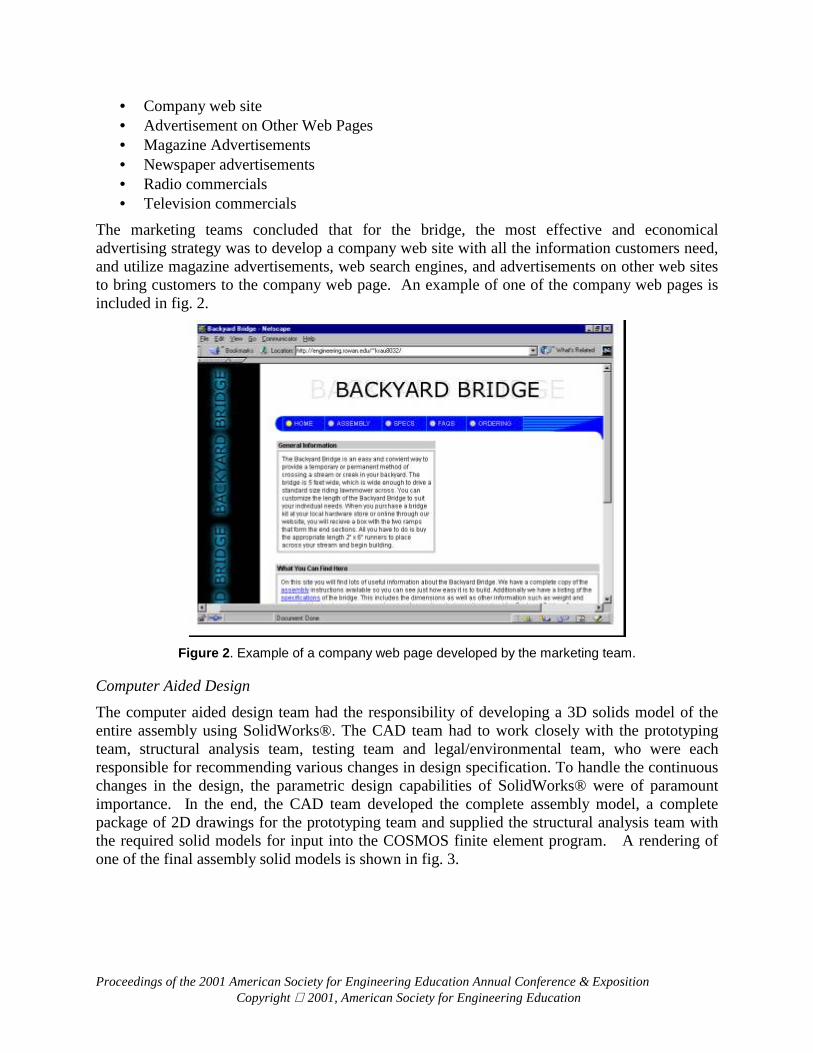
The marketing teams concluded that for the bridge, the most effective and economical advertising strategy was to develop a company web site with all the information customers need, and utilize magazine advertisements, web search engines, and advertisements on other web sites to bring customers to the company web page. An example of one of the company web pages is included in fig. 2.
Figure 2. Example of a company web page developed by the marketing team.
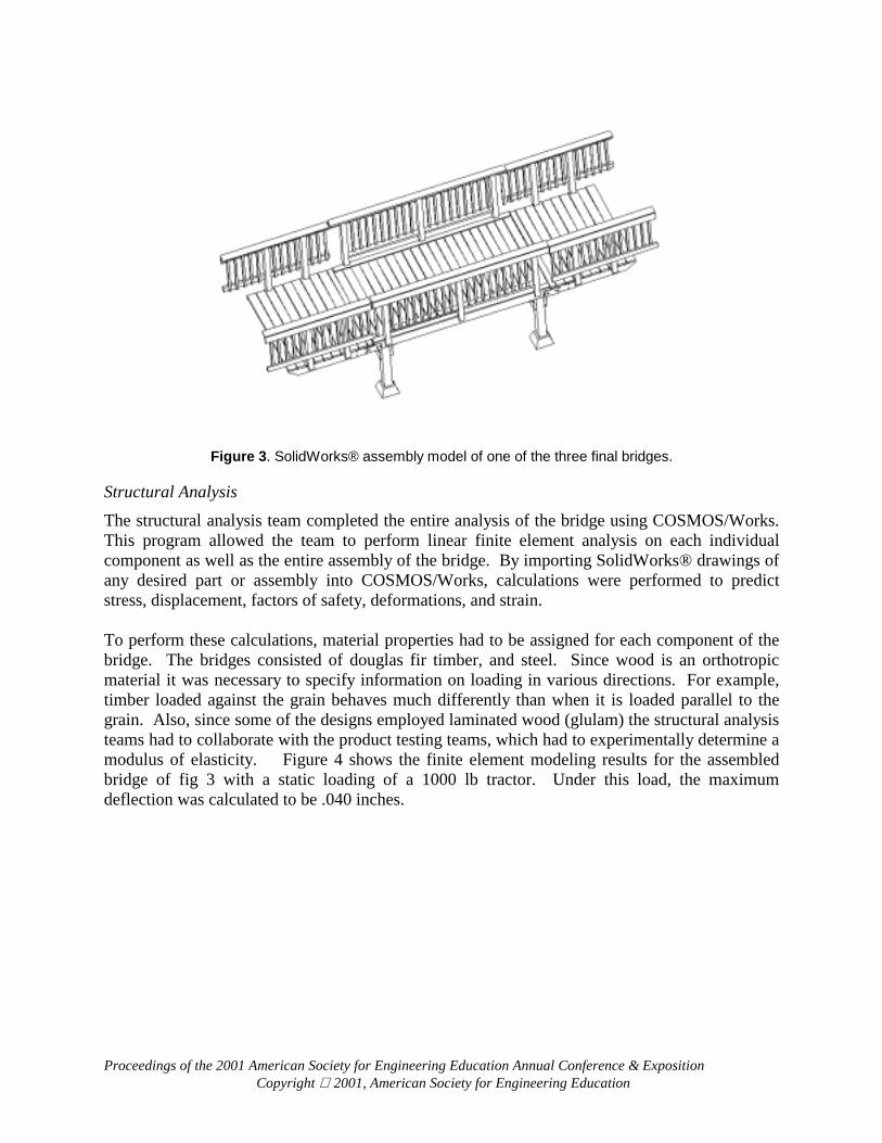
Computer Aided Design The computer aided design team had the responsibility of developing a 3D solids model of the entire assembly using SolidWorks®. The CAD team had to work closely with the prototyping team, structural analysis team, testing team and legal/environmental team, who were each responsible for recommending various changes in design specification. To handle the continuous changes in the design, the parametric design capabilities of SolidWorks® were of paramount importance. In the end, the CAD team developed the complete assembly model, a complete package of 2D drawings for the prototyping team and supplied the structural analysis team with the required solid models for input into the COSMOS finite element program. A rendering of one of the final assembly solid models is shown in fig. 3.
Proceedings of the 2001 American Society for Engineering Education Annual Conference & Exposition Copyright 2001, American Society for Engineering Education
Figure 3. SolidWorks® assembly model of one of the three final bridges.
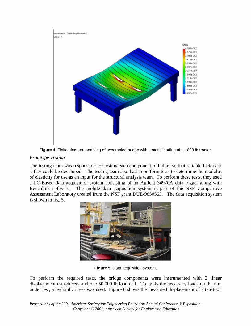
Structural Analysis The structural analysis team completed the entire analysis of the bridge using COSMOS/Works. This program allowed the team to perform linear finite element analysis on each individual component as well as the entire assembly of the bridge. By importing SolidWorks® drawings of any desired part or assembly into COSMOS/Works, calculations were performed to predict stress, displacement, factors of safety, deformations, and strain. To perform these calculations, material properties had to be assigned for each component of the bridge. The bridges consisted of douglas fir timber, and steel. Since wood is an orthotropic material it was necessary to specify information on loading in various directions. For example, timber loaded against the grain behaves much differently than when it is loaded parallel to the grain. Also, since some of the designs employed laminated wood (glulam) the structural analysis teams had to collaborate with the product testing teams, which had to experimentally determine a modulus of elasticity. Figure 4 shows the finite element modeling results for the assembled bridge of fig 3 with a static loading of a 1000 lb tractor. Under this load, the maximum deflection was calculated to be .040 inches.
Proceedings of the 2001 American Society for Engineering Education Annual Conference & Exposition Copyright 2001, American Society for Engineering Education
Figure 4. Finite element modeling of assembled bridge with a static loading of a 1000 lb tractor.
Prototype Testing The testing team was responsible for testing each component to failure so that reliable factors of safety could be developed. The testing team also had to perform tests to determine the modulus of elasticity for use as an input for the structural analysis team. To perform these tests, they used a PC-Based data acquisition system consisting of an Agilent 34970A data logger along with Benchlink software. The mobile data acquisition system is part of the NSF Competitive Assessment Laboratory created from the NSF grant DUE-9850563. The data acquisition system is shown in fig. 5.
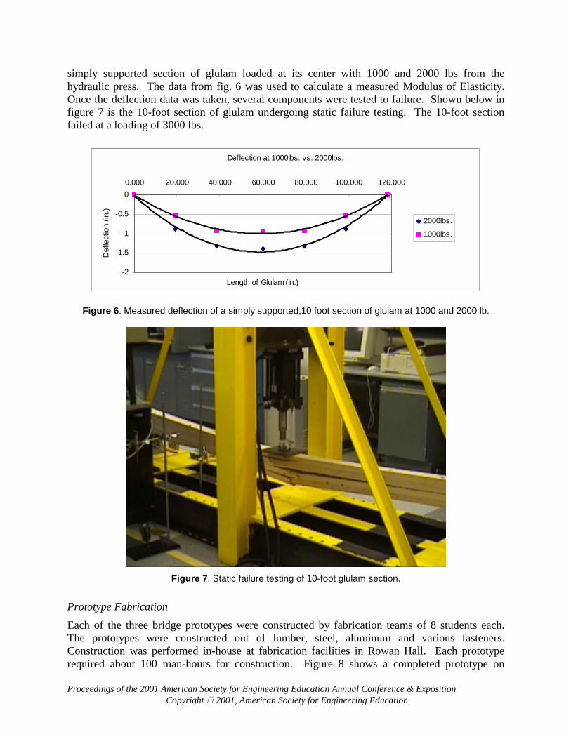
Figure 5. Data acquisition system. To perform the required tests, the bridge components were instrumented with 3 linear displacement transducers and one 50,000 lb load cell. To apply the necessary loads on the unit under test, a hydraulic press was used. Figure 6 shows the measured displacement of a ten-foot,
Proceedings of the 2001 American Society for Engineering Education Annual Conference & Exposition Copyright 2001, American Society for Engineering Education
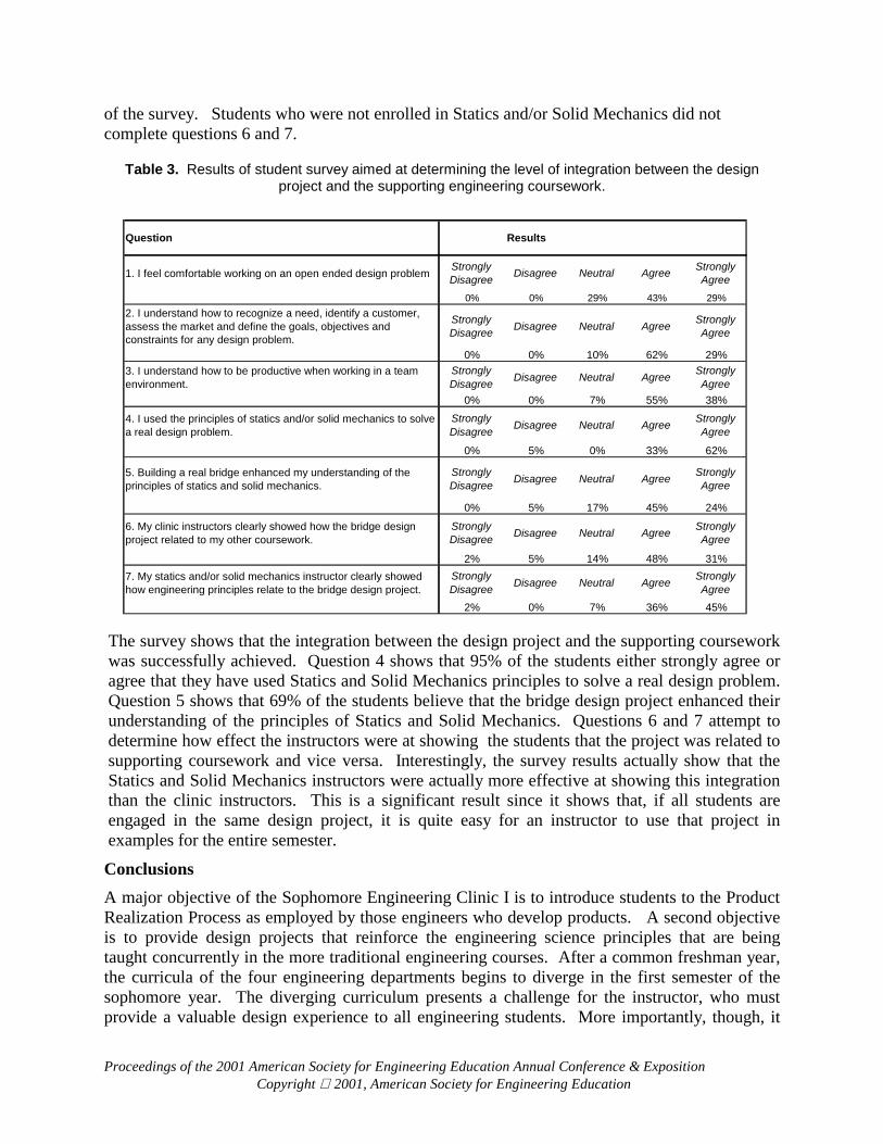
simply supported section of glulam loaded at its center with 1000 and 2000 lbs from the hydraulic press. The data from fig. 6 was used to calculate a measured Modulus of Elasticity. Once the deflection data was taken, several components were tested to failure. Shown below in figure 7 is the 10-foot section of glulam undergoing static failure testing. The 10-foot section failed at a loading of 3000 lbs.
Figure 6. Measured deflection of a simply supported,10 foot section of glulam at 1000 and 2000 lb.
Figure 7. Static failure testing of 10-foot glulam section.
Prototype Fabrication Each of the three bridge prototypes were constructed by fabrication teams of 8 students each. The prototypes were constructed out of lumber, steel, aluminum and various fasteners. Construction was performed in-house at fabrication facilities in Rowan Hall. Each prototype required about 100 man-hours for construction. Figure 8 shows a completed prototype on
Proceedings of the 2001 American Society for Engineering Education Annual Conference & Exposition Copyright 2001, American Society for Engineering Education
display in the Rowan Hall atrium. As can be seen in the figure, the final prototypes were of extremely high quality. Although it was hard work, each team had ownership in their bridge and, ultimately, put in the time required to complete fabrication of the bridge on time.
Figure 8. Complete portable bridge prototype.
Final Design Competition and Investor Reports During the 15th and final week of the semester, each company had to prepare an approximately 40-page document, which was prepared for a potential investor in the company. The report contained a 5 page section from each of the product development teams as well as an introduction, conclusion, appendices and references. The final document was team-written and compiled by a “superteam”, which was populated by one member from each of the product development teams.
During the last day of class, all 108 students met in the atrium of the engineering building for final presentation and final testing of each bridge. The final test of each bridge consisted of measuring the total deflection of the bridge with 20 of its team members standing on it. Total deflections ranged from 0.040 to 0.300 inches under loads of approximately 3000 lbs.
Assessment The portable bridge design project was chosen as a vehicle to teach the product realization process in a way that is directly integrated with the supporting engineering coursework. To determine whether the design project was successful in this regard, a survey was administered to all 108 students. The major goals of the survey were to determine whether or not:
• The design project helped students to better understand the principles of Statics and Solid Mechanics,
• The students were able to apply the principles of Statics and Solid Mechanics during the design of their bridge,
• The clinic instructors showed how the design project related to their supporting coursework, and
• The Statics and Solid Mechanics instructors showed how their courses related to the design project.
The survey also seeks to determine whether the students feel comfortable working in teams and working on open ended design problems. Table 3 contains the survey questions and the results
Proceedings of the 2001 American Society for Engineering Education Annual Conference & Exposition Copyright 2001, American Society for Engineering Education
of the survey. Students who were not enrolled in Statics and/or Solid Mechanics did not complete questions 6 and 7.
Table 3. Results of student survey aimed at determining the level of integration between the design project and the supporting engineering coursework.
The survey shows that the integration between the design project and the supporting coursework was successfully achieved. Question 4 shows that 95% of the students either strongly agree or agree that they have used Statics and Solid Mechanics principles to solve a real design problem. Question 5 shows that 69% of the students believe that the bridge design project enhanced their understanding of the principles of Statics and Solid Mechanics. Questions 6 and 7 attempt to determine how effect the instructors were at showing the students that the project was related to supporting coursework and vice versa. Interestingly, the survey results actually show that the Statics and Solid Mechanics instructors were actually more effective at showing this integration than the clinic instructors. This is a significant result since it shows that, if all students are engaged in the same design project, it is quite easy for an instructor to use that project in examples for the entire semester.
Conclusions A major objective of the Sophomore Engineering Clinic I is to introduce students to the Product Realization Process as employed by those engineers who develop products. A second objective is to provide design projects that reinforce the engineering science principles that are being taught concurrently in the more traditional engineering courses. After a common freshman year, the curricula of the four engineering departments begins to diverge in the first semester of the sophomore year. The diverging curriculum presents a challenge for the instructor, who must provide a valuable design experience to all engineering students. More importantly, though, it
Question Results
1. I feel comfortable working on an open ended design problem Strongly Disagree Disagree Neutral Agree Strongly
Agree0% 0% 29% 43% 29%
2. I understand how to recognize a need, identify a customer, assess the market and define the goals, objectives and constraints for any design problem.
Strongly Disagree Disagree Neutral Agree Strongly
Agree
0% 0% 10% 62% 29%3. I understand how to be productive when working in a team environment.
Strongly Disagree Disagree Neutral Agree Strongly
Agree0% 0% 7% 55% 38%
4. I used the principles of statics and/or solid mechanics to solve a real design problem.
Strongly Disagree Disagree Neutral Agree Strongly
Agree
0% 5% 0% 33% 62%
5. Building a real bridge enhanced my understanding of the principles of statics and solid mechanics.
Strongly Disagree Disagree Neutral Agree Strongly
Agree
0% 5% 17% 45% 24%
6. My clinic instructors clearly showed how the bridge design project related to my other coursework.
Strongly Disagree Disagree Neutral Agree Strongly
Agree
2% 5% 14% 48% 31%7. My statics and/or solid mechanics instructor clearly showed how engineering principles relate to the bridge design project.
Strongly Disagree Disagree Neutral Agree Strongly
Agree2% 0% 7% 36% 45%
Proceedings of the 2001 American Society for Engineering Education Annual Conference & Exposition Copyright 2001, American Society for Engineering Education
represents an opportunity for the student to learn the valuable lesson that they will often be called upon to be a team member (or leader) on a project in which they are not technical experts.
In the portable bridge design project, the mechanical and civil engineering students were concurrently enrolled in Statics and Solid Mechanics. The electrical engineering students were enrolled only in Statics. The chemical engineering students had taken neither Statics nor Solid Mechanics. Although it may seem odd for ChE / EE students to be involved in the design of a portable residential bridge, the clinic experience has proven that these students played a significant role in formulating engineering specifications, generating several concept designs, computer simulation, cost analysis, prototyping and writing the design report.
Our experience has shown that projects which are quite complex in scope can be effectively accomplished as early as the sophomore level. In fact, the “just-in-time” philosophy for teaching engineering design is largely responsible for the overall success of this project. This approach allows for immediate application of theoretical concepts while material is still fresh in students’ minds. The majority of the supporting coursework required to complete this project was provided either just prior to or concurrent with the project. However, like all real-life design projects, many of the technical issues could not be solved using typical textbook solutions. The latter lesson is best learned early. And, by engaging in a series of engineering clinic projects, each unique in their own way, each student will gain an appreciation for the life long learning required for any engineering professional. Bibliography
1. Marchese, A.J., Hesketh, R. P., Jahan, K. (1997) Design in the Rowan University Freshman Engineering Clinic. Proc. Conf. Amer. Soc. Eng. Edu., Session 3225, 1997.
2. Schmalzel, J., Marchese, A. J., and Hesketh, R. P. (1998). What's Brewing in the Engineering Clinic? Hewlett Packard Engineering Educator, Vol. 2, No. 1., p. 6.
3. Schmalzel, J. L., Marchese, A. J., Mariappan, J., and Mandayam, S. (1998). The Engineering Clinic: A Four-Year Design Sequence. 2nd Annual Conference of National Collegiate Invention and Innovation Alliance, Washington, DC.
4 Mariappan, J. and Marchese, A. J. (1998). TQM Approach to Design in the Sophomore Engineering Clinic. ASME International Mechanical Engineering Congress and Exhibition. Anaheim, CA.
5. Harvey, R., Johnson, F., Marchese, A. J., Newell, J. A., Ramachandran, R. P., and Sukumaran, B. (1999). Teaching Quality: An Integrated TQM Approach to Technical Communication and Engineering Design. ASEE Middle Atlantic Regional Meeting, Monmouth University, Spring 1999.
6. Hauser, J. R., and Clausing, D., “The House of Quality,” Harvard Business Review, May-June, 1988.
7. Pugh, S., “Creating Innovative Products Using Total Design,” Addison-Wesley, NY, 1996.


![Sophomore English [EX]](https://static.documents.pub/doc/80x56/568135aa550346895d9d18a5/sophomore-english-ex.jpg)


