i Foreword Welcome to the growing group of value–conscious people who drive Toyotas. We are proud of the advanced engineering and quality construction of each vehicle we build. This Owner’s Manual explains the operation of your new Toyota. Please read it thoroughly and have all the occupants follow the instructions carefully. Doing so will help you enjoy many years of safe and trouble–free motoring. For important information about this manual and your Toyota, read the following pages carefully. When it comes to service, remember that your Toyota dealer knows your vehicle best and is interested in your complete satisfaction. He will provide quality maintenance and any other assistance you may require. If there is not a Toyota dealer near you, or you need emergency assistance for any reason, please call the following number: D U.S. OWNERS: Toyota Customer Assistance Center Toll–free:1–800–331–4331 D CANADIAN OWNERS: Toyota Canada Customer Interaction Center Toll–free:1–888–TOYOTA–8 (1–888–869–6828) Please leave this Owner’s Manual in this vehicle at the time of resale. The next owner will need this information also. All information and specifications in this manual are current at the time of printing. However, because of Toyota’s policy of continual product improvement, we reserve the right to make changes at any time without notice. Please note that this manual applies to all models and explains all equipment, including options. Therefore, you may find some explanations for equipment not installed on your vehicle. 2002 TOYOTA MOTOR CORPORATION All rights reserved. This material may not be reproduced or copied, in whole or in part, without the written permission of Toyota Motor Corporation.
Transcript
i
Foreword
Welcome to the growing group of value–conscious people who drive Toyotas. We are proud of the advanced engineering andquality construction of each vehicle we build.
This Owner’s Manual explains the operation of your new Toyota. Please read it thoroughly and have all the occupantsfollow the instructions carefully. Doing so will help you enjoy many years of safe and trouble–free motoring. Forimportant information about this manual and your Toyota, read the following pages carefully.
When it comes to service, remember that your Toyota dealer knows your vehicle best and is interested in your completesatisfaction. He will provide quality maintenance and any other assistance you may require.
If there is not a Toyota dealer near you, or you need emergency assistance for any reason, please call the following number:
� U.S. OWNERS: Toyota Customer Assistance Center Toll–free:1–800–331–4331
� CANADIAN OWNERS: Toyota Canada Customer Interaction Center Toll–free:1–888–TOYOTA–8 (1–888–869–6828)
Please leave this Owner’s Manual in this vehicle at the time of resale. The next owner will need this information also.
All information and specifications in this manual are current at the time of printing. However, because of Toyota’s policy ofcontinual product improvement, we reserve the right to make changes at any time without notice.
Please note that this manual applies to all models and explains all equipment, including options. Therefore, you mayfind some explanations for equipment not installed on your vehicle.
2002 TOYOTA MOTOR CORPORATION
All rights reserved. This material may not be reproduced or copied, in whole or in part, without the written permission of ToyotaMotor Corporation.
ii
Important information about this manual
Safety and vehicle damage warnings
Throughout this manual, you will see safety and vehicle dam-age warnings. You must follow these warnings carefully toavoid possible injury or damage.
The types of warnings, what they look like, and how they areused in this manual are explained as follows:
CAUTION
This is a warning against anything which maycause injury to people if the warning is ignored.You are informed about what you must or must notdo in order to reduce the risk of injury to yourselfand others.
NOTICE
This is a warning against anything which maycause damage to the vehicle or its equipment if thewarning is ignored. You are informed about whatyou must or must not do in order to avoid or re-duce the risk of damage to your vehicle and itsequipment.
Safety symbol
When you see the safety symbol shownabove, it means: “Do not...”; “Do not dothis”; or “Do not let this happen”.
iii
Important information about your Toyota
New vehicle warranty
Your new vehicle is covered by the following Toyotalimited warranties:
� New vehicle warranty
� Emission control systems warranty
� Others
For further information, please refer to the “Owner’sWarranty Information Booklet” or “Owner’s Manual Sup-plement”.
Your responsibility for maintenance
It is the owner’s responsibility to make sure the speci-fied maintenance is performed. Section 7 gives details ofthese maintenance requirements. Also included in Sec-tion 7 is general maintenance. For scheduled mainte-nance information, please refer to the “Scheduled Main-tenance Guide” or “Owner’s Manual Supplement”.
Accessories, spare parts andmodification of your Toyota
A wide variety of non–genuine spare parts and accesso-ries for Toyota vehicles are currently available in themarket. Using these spare parts and accessories whichare not genuine Toyota products may adversely affectthe safety of your vehicle, even though these parts maybe approved by certain authorities in your country.Toyota therefore cannot accept any liability or guaranteespare parts and accessories which are not genuineToyota products, nor for replacement or installation in-volving such parts.
This vehicle should not be modified with non–genuineToyota products. Modification with non–genuine Toyotaproducts could affect its performance, safety or durabili-ty, and may even violate governmental regulations. Inaddition, damage or performance problems resulting fromthe modification may not be covered under warranty.
iv
Spark ignition system of your Toyota
The spark ignition system in your Toyota meets all re-quirements of the Canadian Interference–Causing Equip-ment Standard.
Installation of a mobiletwo–way radio system
As the installation of a mobile two–way radio system inyour vehicle could affect electronic systems such asmultiport fuel injection system / sequential multiport fuelinjection system, cruise control system, anti–lock brakesystem, SRS airbag system, seat belt pretensioner sys-tem and Toyota hybrid system, be sure to check withyour Toyota dealer for precautionary measures or specialinstructions regarding installation.
Scrapping of your ToyotaThe SRS airbag and seat belt pretensioner devices inyour Toyota contain explosive chemicals. If the vehicle isscrapped with the airbags and pretensioners left as theyare, this may cause an accident such as fire. Be sure tohave the systems of the SRS airbag and seat belt preten-sioner removed and disposed of by the qualified serviceshop or by your Toyota dealer before you dispose of yourvehicle.
CAUTION
When your vehicle or battery needs to be dis-posed of, be sure to consult your Toyota dealer.Hybrid vehicle batteries must be collectedthrough Toyota dealers. If your vehicle is dis-posed of without dismantling, someone couldreceive an electric shock by touching the highvoltage parts of the hybrid vehicle battery. If thebattery is not disposed of properly, its contentscan cause death or serious injury.
v
Hybrid vehicle battery
Hybrid vehicle battery has a limited service life. Callyour Toyota dealer for information concerning recyclingor disposal of hybrid vehicle battery and your vehicle.
CAUTION
Precautions for useof hybrid vehicle
The vehicle has both high voltage DC and AC systems aswell as a 12–volt system. DC and AC high voltage are bothvery dangerous and can cause death or serious injury, se-vere burns and electric shock.
� In order to avoid personal injuries, do not touchthe high voltage cables (orange colored) and theirconnectors.
� Follow the caution labels attached to the high volt-age parts.
� Do not remove or replace the high voltage partssuch as the inverter unit (located in the enginecompartment), hybrid vehicle battery (located be-tween rear seat and trunk), etc.
� Do not touch the service plug located in the leftside trim of the trunk without hybrid system tech-nical training. (See “Precautions for use” on page12 in Section 1–2.) This component is provided todisable the high voltage system in case of servic-ing at a Toyota dealer.
vi
CAUTION
If an accident occurs
� Pull your Toyota off the road, put the selector le-ver in “P” and remove the ignition key.
� In order to avoid personal injuries, do not touchany high voltage wirings and their connectors, andhigh voltage parts (inverter unit, hybrid vehiclebattery, etc.).
� If some exposed electric wirings are protruding in-side or outside of your Toyota, an electric shockmay occur. Never touch the electric wirings.
� If fluid leaks or gets in some parts of the vehicle,never touch it because it may be electrolyte(strong alkali) from the hybrid vehicle battery. If itgets into your skin or eyes, wash off immediatelywith a large amount of water, if possible, boricacid solution, and get immediate medical attentionin order to help avoid serious injury.
� If a vehicle fire occurs, extinguish it using a fireextinguisher for the exclusive use on electric fires.Or, use a large amount of water to prevent flam-mable gas from being generated from the batteries.
� When your Toyota needs to be towed, do it withthe front wheels raised. For details on towing, see“If your vehicle needs to be towed” on page 182 inSection 5.
vii
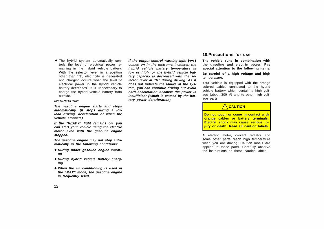
CAUTION
High Voltage
Your vehicle is equipped with cables connected toparts of the vehicle subject to high voltage (about300 V). There are some other parts which reach hightemperatures when you are driving. Never touch bat-tery cables (wrapped in orange–colored harnesses)and their connector since high voltages are appliedand they are dangerous. Caution labels are appliedto these parts to identify them. Carefully observe theinstructions on these caution labels.
00p001
147
103.INFORMATION BEFORE DRIVINGYOUR TOYOTAInformation before driving your TOYOTA
Your vehicle does not need an elaboratebreak–in. But following a few simple tipsfor the first 1000 km (600 miles) can addto the future economy and long life ofyour vehicle:
� Avoid full–throttle acceleration whenstarting and driving.
� Avoid racing the hybrid engine.
� Try to avoid hard stops during the first300 km (200 miles).
FUEL TYPE
Your vehicle must use only unleadedgasoline.
To help prevent gas station mixups, your To-yota has a smaller fuel tank opening. Thespecial nozzle on pumps with unleaded fuelwill fit it, but the larger standard nozzle onpumps with leaded gas will not.
At a minimum, the gasoline you useshould meet the specifications of ASTMD4814 in the U.S.A. and CGSB 3.5–M93in Canada.
NOTICE
Do not use leaded gasoline. Use ofleaded gasoline will cause the three–way catalytic converter to lose itseffectiveness and the emission con-trol system to function improperly.Also, this can increase maintenancecosts.
OCTANE RATING
Select unleaded gasoline with an Oc-tane Rating of 87 (Research OctaneNumber 91) or higher.
Use of unleaded fuel with an octane num-ber or rating lower than stated above willcause persistent heavy knocking. If se-vere, this will lead to engine damage.
If your engine knocks ...
If you detect heavy knocking even whenusing the recommended fuel, or if youhear steady knocking while holding asteady speed on level roads, consult yourToyota dealer.
However, occasionally, you may noticelight knocking for a short time while accel-erating or driving up hills. This is normaland there is no need for concern.
GASOLINE CONTAINING DETERGENTADDITIVES
Toyota recommends the use of gasoline thatcontains detergent additives to avoid build–up of engine deposits.
However, all gasoline sold in the U.S. con-tains detergent additives to keep clean and/orclean intake systems.
104.Break–in period 105.Fuel
149
QUALITY GASOLINE
Automotive manufacturers in the U.S., Eu-rope and Japan have developed a specifica-tion for quality fuel named World–WideFuel Charter (WWFC) that is expected tobe applied world wide. The WWFC consistsof three categories that depend on requiredemission levels. In the U.S., category 3 hasbeen adopted. The WWFC improves airquality by providing for better emissions invehicle fleets, and customer satisfactionthrough better vehicle performance.
CLEANER BURNING GASOLINE
Cleaner burning gasoline, including refor-mulated gasoline that contains oxygenatessuch as ethanol or MTBE is available inmany areas.
Toyota recommends the use of cleanerburning gasoline and appropriately blendedreformulated gasoline. These types of gas-oline provide excellent vehicle perfor-mance, reduce vehicle emissions, and im-prove air quality.
OXYGENATES IN GASOLINE
Toyota allows the use of oxygenate blendedgasoline where the oxygenate content is upto 10% ethanol or 15% MTBE. If you usegasohol in your Toyota, be sure that it hasan octane rating no lower than 87.
Toyota does not recommend the use ofgasoline containing methanol.
GASOLINE CONTAINING MMT
Some gasoline contain an octane en-hancing additive called MMT (Methylcy-clopentadienyl Manganese Tricarbonyl).
Toyota does not recommend the use ofgasoline that contains MMT. If fuel con-taining MMT is used, your emission con-trol system may be adversely affected.The Malfunction Indicator Lamp on the in-strument cluster may come on. If this hap-pens, contact your Toyota dealer for ser-vice.
GASOLINE QUALITY
In a very few cases, you may experiencedriveability problems caused by the partic-ular gasoline that you are using. If youcontinue to have unacceptable driveability,try changing gasoline brands. If this doesnot rectify your problem, then consult yourToyota dealer.
NOTICE
� Do not use gasohol other thanstated above. It will cause fuel sys-tem damage or vehicle performanceproblems.
� If drivability problems are encoun-tered (poor hot starting, vaporizing,engine knock, etc.), discontinue itsuse.
� Take care not to spill gasohol dur-ing refueling. Gasohol may causepaint damage.
150
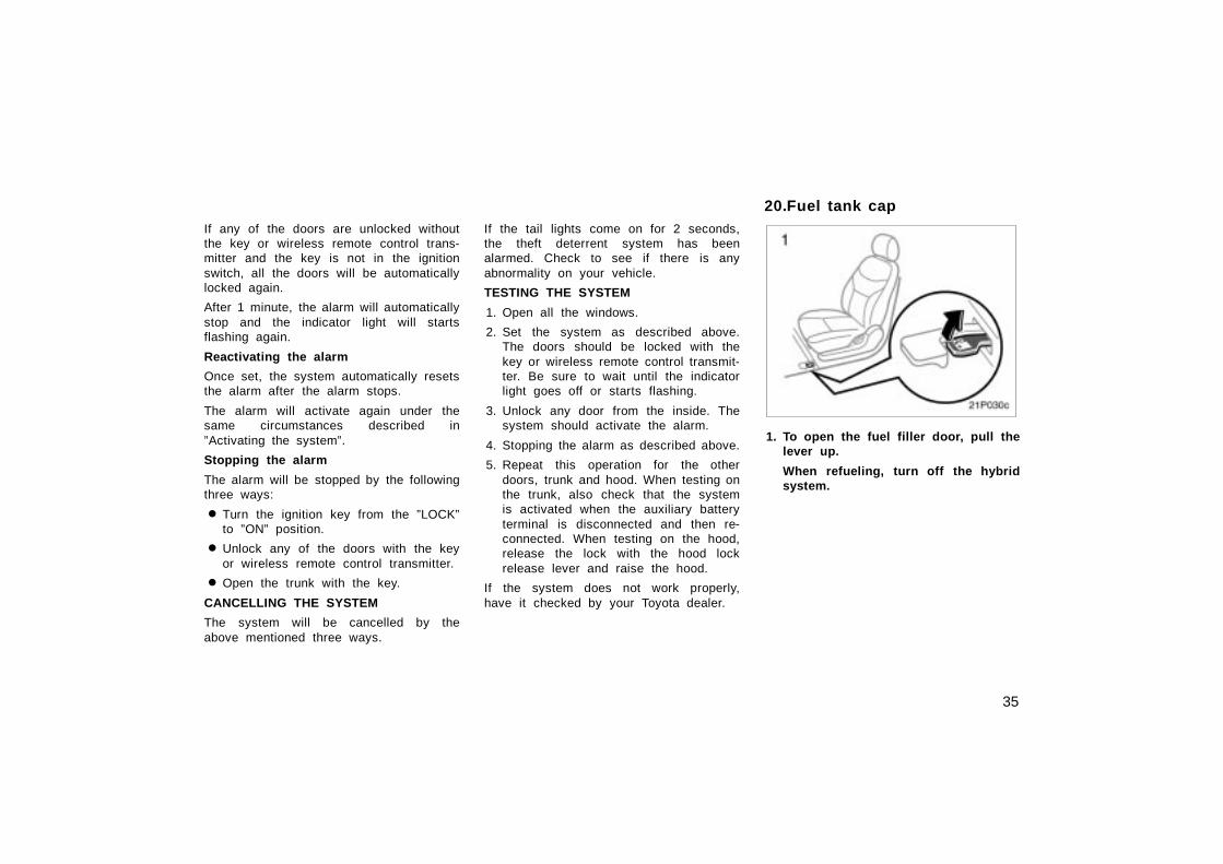
106.FUEL TANK CAPACITY
45 L (11.9 gal., 9.9 lmp. gal.)
The given fuel tank capacity is measuredon EPA/CARB ORVR testing conditionwhich is approved for nominal capacitymeasurement condition.
The fuel tank capacity is decreased at lowambient temperature. (decreased by about5 L (1.3 gal., 1.1 lmp. gal.) at –10�C(14�F).)
107.Fuel pump shut–off systemThe fuel pump shut–off system stops sup-plying fuel to the engine to minimize therisk of fuel leakage when the engine stallsor an airbag inflates upon collision. Torestart the hybrid system after the fuelpump shut–off system activates, turn theignition switch to “ACC” or “LOCK” onceand start it.
CAUTION
Inspect the ground under the vehiclebefore restarting the hybrid system. Ifyou find that liquid has leaked ontothe ground, the fuel system has beendamaged and it is in need of repair.In this case, do not restart the hybridsystem.
If you plan to drive your Toyota inanother country...
First , comply with the vehicle registrationlaws.
Second , confirm the availability of the cor-rect fuel (unleaded and minimum octanenumber).
108.Operation in foreign countries
151
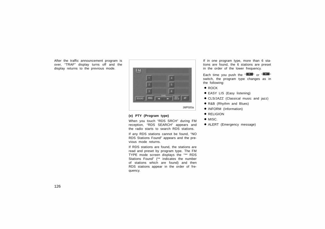
30p001b
1. Three–way catalytic converter
2. Toyota HC adsorber and catalyst sys-tem
The three–way catalytic converter andToyota HC adsorber and catalyst systemare emission control devices installedin the exhaust system.
Its purpose is to reduce pollutants in theexhaust gas.
CAUTION
� Keep people and combustible mate-rials away from the exhaust pipewhile the engine is running. Theexhaust gas is very hot.
� Do not drive, idle or park your ve-hicle over anything that might burneasily such as grass, leaves, paperor rags.
NOTICE
A large amount of unburned gasesflowing into the three–way catalyticconverter and Toyota HC adsorberand catalyst system may cause it tooverheat and create a fire hazard. Toprevent this and other damage, ob-serve the following precautions:
� Use only unleaded gasoline.
� Do not drive with an extremely lowfuel level; running out of fuel couldcause the engine to misfire, creat-ing an excessive load on the three–way catalytic converter and ToyotaHC adsorber and catalyst system.
� Do not turn off the ignition whilethe vehicle is moving.
� Keep your engine in good runningorder. Malfunctions in the engineelectrical system, electronic ignitionsystem/distributor ignition systemor fuel system could cause an ex-tremely high temperature of three–way catalytic converter and ToyotaHC adsorber and catalyst system.
109.Three–way catalyticconverterToyota HC adsorber andcatalyst system
152
� If the engine becomes difficult tostart or stalls frequently, take yourvehicle in for a check–up as soonas possible. Remember, your Toyotadealer knows your vehicle and itsthree–way catalytic converter andToyota HC adsorber and catalystsystem best.
� To ensure that the three–way cata-lytic converter and Toyota HC ad-sorber and catalyst system and theentire emission control system op-erate properly, your vehicle mustreceive the periodic inspections re-quired by the Toyota MaintenanceSchedule. For scheduled mainte-nance information, refer to the”Scheduled Maintenance Guide” or”Owner’s Manual Supplement”.
� Do not apply coating agent such asfor anti–rust under–coating to theexhaust pipe (especially to the ac-tuator to valve).
CAUTION
� Avoid inhaling the engine exhaust.It contains carbon monoxide, whichis a colorless and odorless gas. Itcan cause unconsciousness or evendeath.
� Make sure the exhaust system hasno holes or loose connections. Thesystem should be checked fromtime to time. If you hit something,or notice a change in the sound ofthe exhaust, have the systemchecked immediately.
� Do not run the hybrid system in agarage or enclosed area except forthe time needed to drive the vehiclein or out. The exhaust gases cannotescape, making this a particularlydangerous situation.
� Do not remain for a long time in aparked vehicle with the hybrid sys-tem running. If it is unavoidable,however, do so only in an uncon-fined area and adjust the heating orcooling system to force outside airinto the vehicle.
� Keep the trunk lid closed whiledriving. An open or unsealed trunklid may cause exhaust gases to bedrawn into the vehicle.
� To allow proper operation of yourvehicle’s ventilation system, keepthe inlet grilles in front of the wind-shield clear of snow, leaves, or oth-er obstructions.
� If you smell exhaust fumes in thevehicle, drive with the windowsopen and the trunk lid closed. Havethe cause immediately located andcorrected.
110.Engine exhaust cautions
153
FUNCTIONS OF ENGINE OIL
Engine oil has the primary functions oflubricating and cooling the inside of theengine, and plays a major role in main-taining the engine in proper working order.
ENGINE OIL CONSUMPTION
It is normal that an engine should con-sume some engine oil during normalengine operation. The causes of oilconsumption in a normal engine are asfollows.
� Oil is used to lubricate pistons, pistonrings and cylinders. A thin film of oilis left on the cylinder wall when apiston moves downwards in the cylin-der. High negative pressure generatedwhen the vehicle is decelerating suckssome of this oil into the combustionchamber. This oil as well as some partof the oil film left on the cylinder wallis burned by the high temperature com-bustion gases during the combustionprocess.
� Oil is also used to lubricate the stemsof the intake valves. Some of this oilis sucked into the combustion chambertogether with the intake air and isburned along with the fuel. High tem-perature exhaust gases also burn theoil used to lubricate the exhaust valvestems.
The amount of engine oil consumed de-pends on the viscosity of the oil, thequality of the oil and the conditions thevehicle is driven under.
More oil is consumed by high–speed driv-ing and frequent acceleration and decel-eration.
A new engine consumes more oil, sinceits pistons, piston rings and cylinder wallshave not become conditioned.
When judging the amount of oil con-sumption, note that the oil may becomediluted and make it difficult to judgethe true level accurately.
As an example, if a vehicle is used forrepeated short trips, and consumes a nor-mal amount of oil, the dipstick may notshow any drop in the oil level at all, evenafter 1000 km (600 miles) or more. Thisis because the oil is gradually becomingdiluted with fuel or moisture, making itappear that the oil level has not changed.
The diluting ingredients evaporate outwhen the vehicle is then driven at highspeeds, as on an expressway, making itappear that oil is excessively consumedafter driving at high speeds.
IMPORTANCE OF ENGINE OIL LEVELCHECK
One of the most important points in prop-er vehicle maintenance is to keep the en-gine oil at the optimum level so that oilfunction will not be impaired. Therefore, itis essential that the oil level be checkedregularly. Toyota recommends that the oillevel be checked every time you refuelthe vehicle.
NOTICE
Failure to check the oil level regularlycould lead to serious engine troubledue to insufficient oil.
111.Facts about engine oil consumption
154
For detailed information on oil level check,see “Checking the engine oil level” onpage 212 in Section 8–2.
Your engine is fitted with iridium–tippedspark plugs.
NOTICE
Use only iridium–tipped spark plugsand do not adjust gaps for your en-gine performance and smooth drivabil-ity.
REGENERATIVE BRAKE
When the brake is applied, the electricmotor used as a generator converts kinet-ic energy into electric energy.
The regenerative brake works in the fol-lowing operations.
1. When the accelerator pedal is re-leased, the reduced speed equal to en-gine braking in a gasoline–fueled ve-hicle is obtained in accordance with therunning mode position of the selectorlever.
2. When the brake pedal is depressedwith the selector lever in “D” or “B”,the regenerative brake works.
112.Iridium–tipped spark plugs 113.Brake system
155
HYDRAULIC BRAKE
This brake system has 2 independent hy-draulic circuits. If either circuit should fail,the other will still work. However, the ped-al will be harder to press, and your stop-ping distance will be longer. Also, thebrake system warning light may come on.
CAUTION
Do not drive your vehicle with only asingle brake system. Have yourbrakes fixed immediately.
BRAKE BOOSTER
The brake booster uses brake fluid pres-surized by the pump to power–assist thebrakes. If the brake booster fails duringdriving, the brake system warning lightcomes on and buzzer sounds continuous-ly. In this case, the brakes may not workproperly. If they do not work well, depressthe brake pedal firmly. If the brake systemwarning light comes on, immediately stopyour vehicle and contact your Toyota deal-er.
The brake system warning light may stayon for about 60 seconds after the ignitionkey is turned to the “ON” position. It isnormal if the light turns off after a while.
Depressing the brake pedal repeatedlymay turn on the brake system warninglight and buzzer. It is normal if the lightturns off and the buzzer stops soundingafter a few seconds.
You may hear a small sound in the enginecompartment after the hybrid system isstarted or the brake pedal is depressedrepeatedly. This is a pump pulsatingsound of the brake system, and it is nota malfunction.
CAUTION
� Do not pump the brake pedal if thehybrid system is not operating.Each push on the pedal uses upyour reserved brake fluid pressure.
� Even if the power assist is com-pletely lost, the brakes will stillwork. But you will have to push thepedal hard, much harder than nor-mal. And your braking distance willbe longer.
ANTI–LOCK BRAKE SYSTEM
The anti–lock brake system is designedto automatically help prevent lock–up ofthe wheels during a sudden braking orbraking on slippery road surfaces. Thisassists in providing directional stab ilityand steering performance of the vehicleunder these circumstances.
Effective way to press the ABS brakepedal: When the anti–lock brake systemfunction is in action, you may feel thebrake pedal pulsating and hear a noise.In this situation, to let the anti–lockbrake system work for you, just hold thebrake pedal down more firmly. Do notpump the brake in a panic stop. Thiswill result in reduced braking perfor-mance.
The anti–lock brake system becomes op-erative after the vehicle has acceleratedto a speed in excess of approximately 10km/h (6 mph). It stops operating when thevehicle decelerates to a speed belowapproximately 5 km/h (3 mph).
156
Depressing the brake pedal on slipperyroad surfaces such as on the manholecover, the steel plate under the construc-tion, joints in the bridge, etc. on a rainyday tends to activate the anti–lock brakesystem.
You may hear a click or motor sound inthe engine compartment for a few secondswhen the engine is started or just afterthe vehicle is started. This means that theanti–lock brake system is in the selfcheck mode, and does not indicate a mal-function.
When the anti–lock brake system is ac-tivated, the following conditions mayoccur. They do not indicate a malfunc-tion of the system:
� You may hear the anti–lock brake sys-tem operating and feel the brake pedalpulsating and the vibrations of the ve-hicle body and steering wheel. Youmay also hear the motor sound in theengine compartment even after the ve-hicle is stopped.
� At the end of the anti–lock brake sys-tem activation, the brake pedal maymove a little forward.
CAUTION
Do not overestimate the anti–lockbrake system: Although the anti–lockbrake system assists in providing ve-hicle control, it is still important todrive with all due care and maintaina moderate speed and safe distancefrom the vehicle in front of you, be-cause there are limits to the vehiclestability and effectiveness of steeringwheel operation even with the anti–lock brake system on.
If tires grip performance exceeds itscapability, or if hydroplaning occursduring high speed driving in the rain,the anti–lock brake system does notprovide vehicle control.
Anti–lock brake system is not de-signed to shorten the stopping dis-tance: Always drive at the moderatespeed and maintain a safe distancefrom the vehicle in front of you.Compared with vehicles without ananti–lock brake system, your vehiclemay require a longer stopping dis-tance in the following cases:
� Driving on rough, gravel or snow–covered roads.
� Driving with tire chains installed.
� Driving over the steps such as thejoints on the road.
� Driving on roads where the roadsurface is pitted or has other differ-ences in surface height.
Install all 4 tires of specified size atappropriate pressure: The anti–lockbrake system detects vehicle speedsusing the speed sensors for respec-tive wheels’ turning speeds. The useof tires other than specified may failto detect the accurate turning speed,resulting in a longer stopping dis-tance.
157
30p002a
Vehicle sold in U.S.A.
30p007a
Vehicle sold in Canada
“ABS” warning light
The light comes on when the ignitionkey is turned to the “ON” position. Ifthe anti–lock brake system works prop-erly, the light turns off after a few sec-onds. Thereafter, if the system malfunc-tions, the light comes on again.
When the “ABS” warning light is on (andthe brake system warning light is off), theanti–lock brake system does not operate,but the brake system still operates con-ventionally.
When the “ABS” warning light is on (andthe brake system warning light is off), theanti–lock brake system does not operateso that the wheels could lock up duringa sudden braking or braking on slipperyroad surfaces.
If either of the following conditions oc-curs, this indicates a malfunction some-where in the parts monitored by thewarning light system. Contact yourToyota dealer as soon as possible toservice the vehicle.
� The light does not come on when theignition key is turned to the “ON” posi-tion, or remains on.
� The light comes on while you are driv-ing.
A warning light turning on briefly duringoperation does not indicate a problem.
CAUTION
If the “ABS” warning light remains ontogether with the brake system warn-ing light, immediately stop your ve-hicle at a safe place and contact yourToyota dealer.
In this case, not only the anti–lockbrake system will fail but also thevehicle will become extremely unsta-ble during braking.
Either of the following conditions mayoccur, but does not indicate the mal-function:
� The light may stay on for about 60seconds after the ignition key is turnedto the “ON” position. It is normal if itturns off after a while.
� Depressing the brake pedal repeatedlymay turn on the light. It is normal ifit turns off after a few seconds.
158
30p003
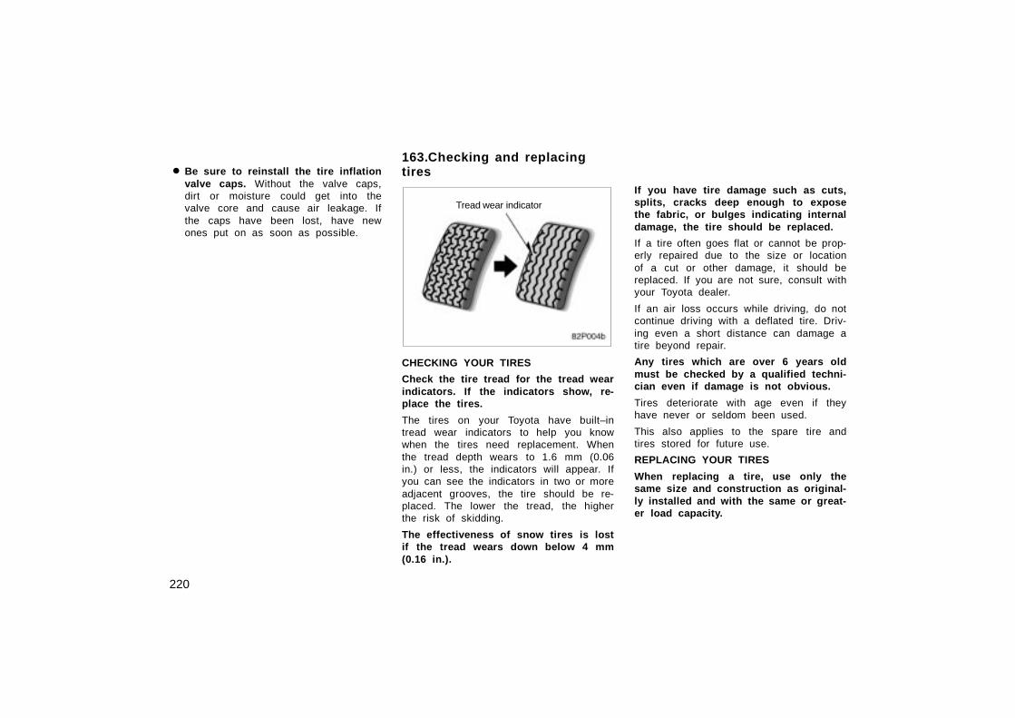
The brake pad wear limit indicators onyour disc brakes give a warning noisewhen the brake pads are worn to wherereplacement is required.
If you hear a squealing or scraping noisewhile driving, have the brake padschecked and replaced by your Toyotadealer as soon as possible. Expensive ro-tor damage can result if the pads are notreplaced when necessary.
When stowing luggage or cargo in thevehicle, observe the following:
� Put luggage or cargo in the trunk whenat all possible. Be sure all items aresecured in place.
� Be careful to keep the vehicle bal-anced. Locating the weight as far for-ward as possible helps maintain bal-ance.
� For better fuel economy, do not carryunneeded weight.
CAUTION
� Do not place anything on the pack-age tray behind the rear seatbackor luggage cover. Such items maybe thrown about and possibly injurepeople in the vehicle during suddenbraking or an accident.
� Do not drive with objects left ontop of the instrument panel. Theymay interfere with the driver’s fieldof view. Or they may move duringsharp vehicle acceleration or turn-ing, and impair the driver’s controlof the vehicle. In an accident theymay injure the vehicle occupants.
NOTICE
Do not load the vehicle beyond thevehicle capacity weight given in Sec-tion 9.
114.Brake pad wear limitindicators
115.Luggage stowageprecautions
159
30p004a
The vehicle identification number (VIN)is the legal identifier for your vehicle.This number is on the left top of theinstrument panel, and can be seenthrough the windshield from outside.
This is the primary identification numberfor your Toyota. It is used in registeringthe ownership of your vehicle.
30p005a
The vehicle identification number (VIN) isalso on the Certification Label.
30p006a
Engine number
Motor number
The engine and motor number platesare installed on the engine and trans-axle case as shown.
Your Toyota’s identification——Vehicle identification116. number —Engine and motor number
160
117.Theft prevention labelsYour new vehicle carries theft preven-tion labels which are approximately 56mm (2.20 in.) by 16 mm (0.63 in.).
The purpose of these labels is to reducethe incidence of vehicle thefts by facilitat-ing the tracing and recovery of parts fromstolen vehicles. The label is designed sothat once it is applied to a surface, anyattempt to remove it will result in destroy-ing the integrity of the label. Transferringthese labels intact from one part to anoth-er, will be impossible.
NOTICE
You should not attempt to remove thetheft prevention labels as it may vio-late certain state or federal laws.
CAUTION
Do not modify the suspension/chassiswith lift kits, spacers, springs, etc. Itcan cause dangerous handling charac-teristics, resulting in loss of control.
119.Types of tiresDetermine what kind of tires your ve-hicle is originally equipped with.
1. All season tires
All season tires are designed to providebetter traction in snow and to be adequatefor driving in most winter conditions, aswell as for use all year round.
All season tires, however, do not haveadequate traction performance comparedwith snow tires in heavy or loose snow.Also, all season tires fall short in accel-eration and handling performancecompared with summer tires in highwaydriving.
2. Summer tires
Summer tires are high–speed capabilitytires best suited to highway driving underdry conditions.
Since summer tires do not have the sametraction performance as snow tires, sum-mer tires are inadequate for driving onsnow–covered or icy roads. For driving onsnow–covered or icy roads, we recom-mend using snow tires. If installing snowtires, be sure to replace all four tires.
118.Suspension and chassis
161
CAUTION
� Do not mix summer and all seasontires on your vehicle as this cancause dangerous handling charac-teristics, resulting in loss of con-trol.
� Do not use tire other than themanufacturer’s designated tires, andnever mix tires or wheels of thesizes different from the originallyequipped tires and wheels.
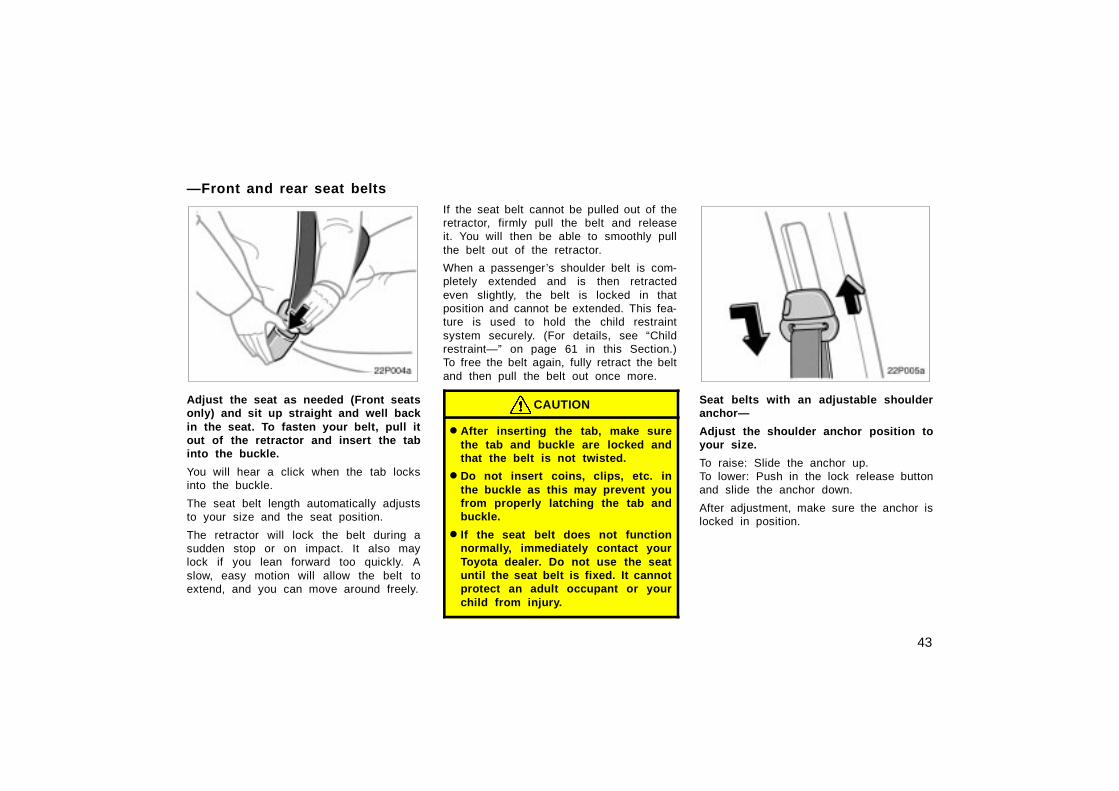
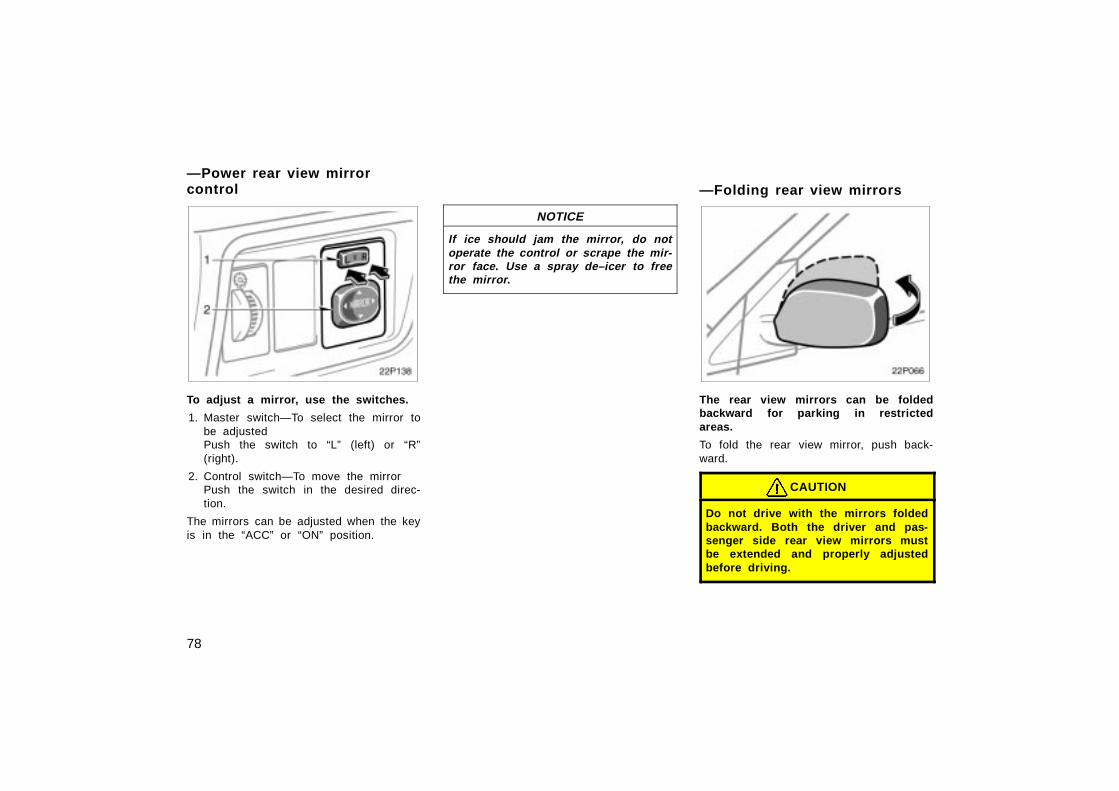
3. Adjust the inside and outside rear viewmirrors.
4. Lock all doors.
5. Fasten seat belts.
When you get in the vehicle, checkwhether the “READY” light is on ornot.
CAUTION
Your vehicle does not produce anynoise or vibration when the vehicle isready to start with the “READY” lighton. Be careful not to start the vehicleabruptly by depressing the accelera-tor pedal inadvertently.
40p001b
1. Apply the parking brake firmly.
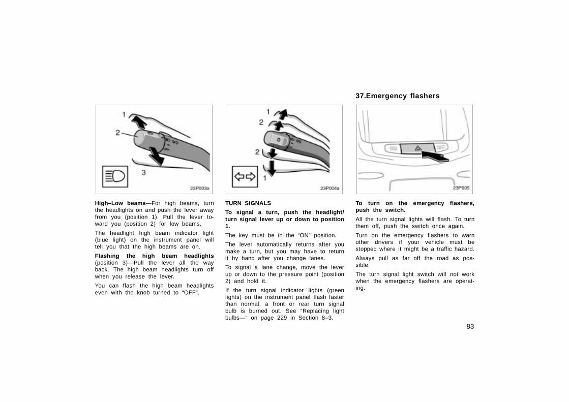
2. Turn off unnecessary lights and acces-sories.
3. Put the running mode selector lever in”P”.
4. Depress the brake pedal and hold itto the floor until driving off.
40p002a
Before starting the hybrid system, be sureto follow the instructions in “(a) Beforestarting the hybrid system”.
Normal starting procedure
Turn and hold the ignition switch to“START” with the brake pedal depressed.The “READY” light starts blinking. After afew seconds, the blinking “READY” lightremains on and a beep sounds. (If theambient temperature is low, such as dur-ing winter driving conditions, it may taketime until the “READY” light is on.) Thenrelease your hand from the ignition switch.
Before starting the hybridsystem121.
How to start the hybridsystem— (a) Before startingthe hybrid system122.
(b) Turning on the hybridsystem
165
When the ignition switch is turned to onor off, you may hear a sound coming fromthe hybrid vehicle battery in the trunk.However, this does not indicate anytrouble.
NOTICE
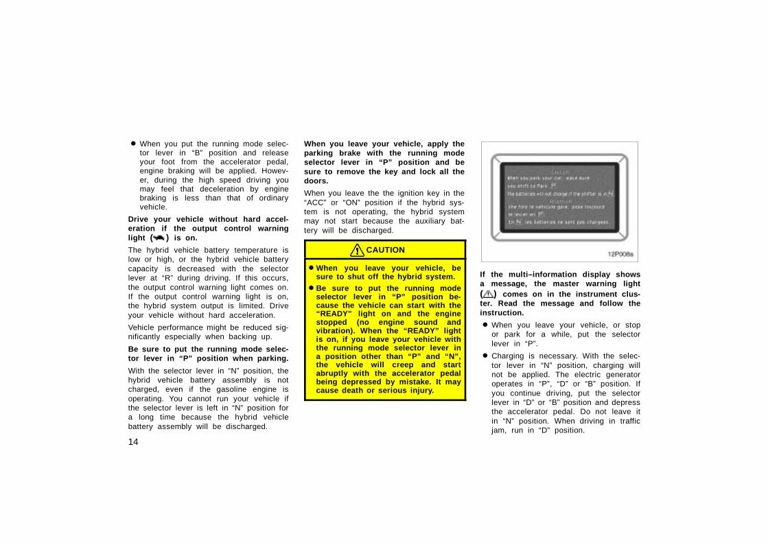
The “READY” light does not come onwhen the selector lever is put in aposition other than “P”. Depress thebrake pedal and put the selector leverin “P” and turn the ignition switch to“START” again.
If there is a problem somewhere in thehybrid system, the hybrid system malfunc-tion warning light will come on in place ofthe “READY” light. If this happens, contactToyota dealer.
NOTICE
When you start the hybrid system ata lowered outside temperature, it maytake longer before the blinking“READY” light changes to stay on.
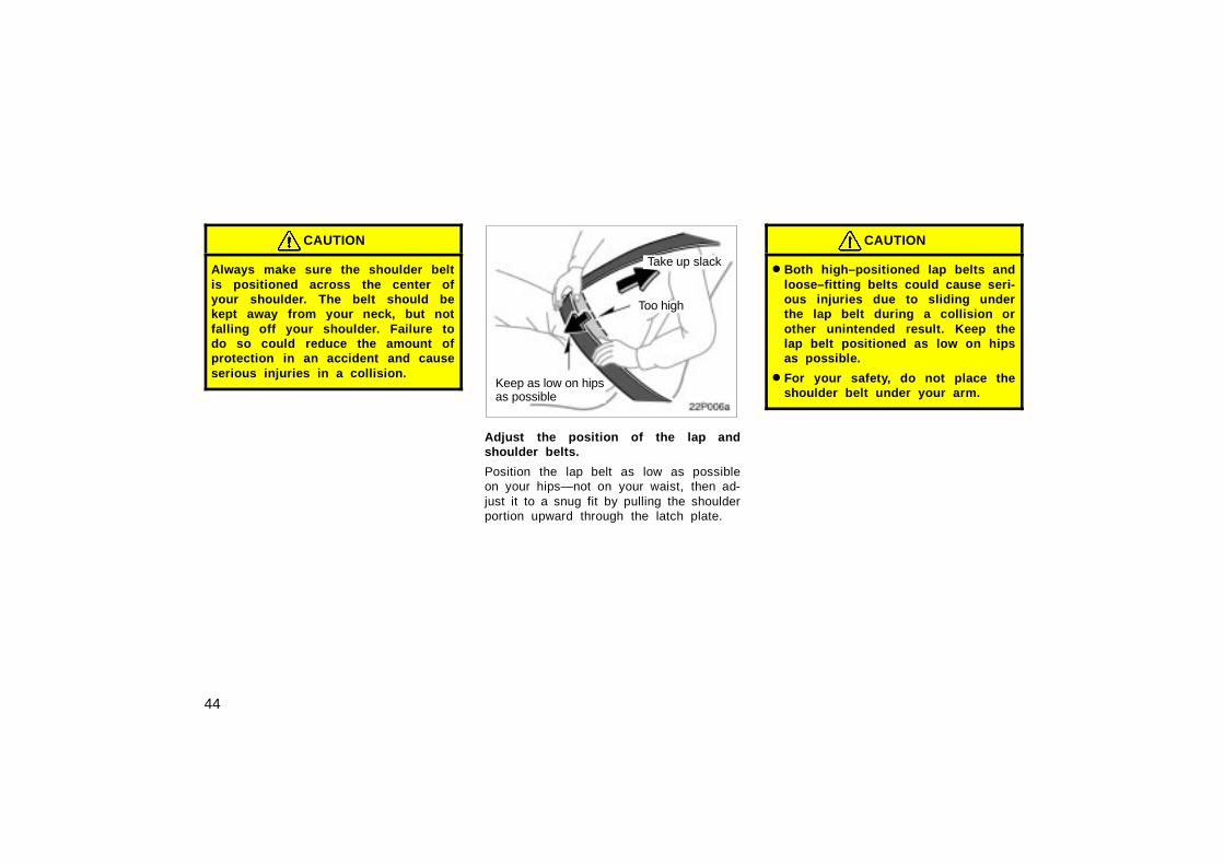
� Always slow down in gusty crosswinds.This will allow you much better control.
� Drive slowly onto curbs and, if pos-sible, at a right angle. Avoid drivingonto high, sharp–edged objects andother road hazards. Failure to do socan lead to severe tire damage result-ing in tire bursts.Drive slowly when passing over bumpsor travelling on a bumpy road. Other-wise, the impact could cause severedamage to the tires and/or wheels.
� When parking on a hill, turn the frontwheels until they touch the curb sothat the vehicle will not roll. Apply theparking brake, and put the selector le-ver into “P”. If necessary, block thewheels.
� Washing your vehicle or driving throughdeep water may get the brakes wet. Tosee whether they are wet, check thatthere is no traffic near you, and thenpress the pedal lightly. If you do notfeel a normal braking force, the brakesare probably wet. To dry them, drivethe vehicle cautiously while lightlypressing the brake pedal with the park-ing brake pulled. If they still do notwork safely, pull to the side of the roadand call a Toyota dealer for assistance.
CAUTION
� Before driving off, make sure theparking brake is fully released andthat the parking brake reminderlight is off.
� Do not leave your vehicle unat-tended with the “READY” light on.
� Do not rest your foot on the brakepedal while driving. It can causedangerous overheating, needlesswear, and poor fuel economy.
� To drive down a long or steep hill,reduce your speed and downshift.Remember, if you ride the brakesexcessively, they may overheat andnot work properly.
� Be careful when accelerating orbraking on a slippery surface. Sud-den acceleration or engine braking,could cause the vehicle to spin orskid.
Tips for driving in variousconditions123.
166
� Do not drive in excess of the speedlimit. Even if the legal speed limitpermits it, do not drive over 140km/h (85 mph) unless your vehiclehas high–speed capability tires.Driving over 140 km/h (85 mph)may result in tire failure, loss ofcontrol and possible injury. Be sureto consult a tire dealer to determinewhether the tires on your vehicleare high–speed capability tires ornot before driving at such speeds.
� Do not continue normal drivingwhen the brakes are wet. If they arewet, your vehicle will require a lon-ger stopping distance, and it maypull to one side when the brakesare applied. Also, the parking brakewill not hold the vehicle securely.
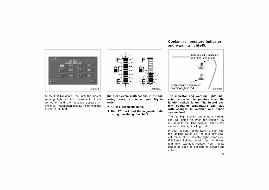
Make sure you have a proper freezeprotection of coolant.
Your coolant must contain ethylene–glycoltype coolant for a proper corrosionprotection of aluminum components. Use“Toyota Genuine Long Life Coolant” orequivalent.
See 215 page in Section 8–2 for detailsabout coolant type selection.
NOTICE
Do not use alcohol type antifreeze orplain water alone.
When it is extremely cold, we recommendto use 60% solution for your Toyota, toprovide protection down to about –50°C(–58°F). Do not use more than 70% solu-tion for better coolant performance.
Check the condition of the aux iliarybattery and cables.
Cold temperatures reduce the capacity ofany auxiliary battery, so it must be in topshape to provide enough power for winterstarting. Section 8–3 tells you how tovisually inspect the auxiliary battery. YourToyota dealer will be pleased to check thelevel of charge.
Make sure the engine oil viscosity issuitable for the cold weather.
See 213 page in Section 8–2 for recom-mended viscosity. Leaving a heavy sum-mer oil in your vehicle during wintermonths may cause harder starting. If youare not sure about which oil to use, callyour Toyota dealer—he will be pleased tohelp.
Keep the door locks from freezing.
Squirt lock de–icer or glycerine into thelocks to keep them from freezing.
Use a washer fluid containing an anti–freeze solution.
This product is available at your Toyotadealer and most auto parts stores. Followthe manufacturer’s directions for howmuch to mix with water.
NOTICE
Do not use engine antifreeze or anyother substitute as washer fluid be-cause it may damage your vehicle’spaint.
Winter driving tips124.
167
Do not use your parking brake whenthere is a possibility it could freeze.
When parking, put the selector lever into“P” and block the rear wheels. Do not usethe parking brake, or snow or water accu-mulated in and around the parking brakemechanism may freeze, making it hard torelease.
Keep ice and snow from accumulatingunder the fenders.
Ice and snow built up under your fenderscan make steering difficult. During badwinter driving, stop and check under thefenders occasionally.
Depending on where you are driving,we recommend you carry some emer-gency equipment.
Some of the things you might put in thevehicle are tire chains, window scraper,bag of sand or salt, flares, small shovel,jumper cables, etc.
40p050
Your vehicle is not designed to bedinghy towed (with four wheels on theground) behind a motorhome.
NOTICE
Do not tow your vehicle with fourwheels on the ground. This maycause serious damage to your ve-hicle.
40p003a
Toyota does not recommend towing atrailer with your Toyota. It is not de-signed for trailer towing.
125.Dinghy towing Trailer towing126.
168
Improving fuel economy is easy–just takeit easy. It will help make your vehicle lastlonger, too. Here are some specific tipson how to save money on both fuel andrepairs:
� Keep your tires inflated at the cor-rect pressure. Underinflation causestire wear and wastes fuel. See page219 in Section 8–2 for instructions.
� Do not carry unneeded weight inyour vehicle. Excess weight puts aheavier load on the engine, causinggreater fuel consumption.
� Accelerate slowly and smoothly.Avoid jackrabbit starts.
� Avoid continuous speeding up andslowing down. Stop–and–go drivingwastes power.
� Avoid unnecessary stopping andbraking. Maintain a steady pace. Tryto time the traffic signals so you onlyneed to stop as little as possible ortake advantage of through streets toavoid traffic lights. Keep a proper dis-tance from other vehicles to avoid sud-den braking. This will also reduce wearon your brakes.
� Avoid heavy traffic or traffic jamswhenever possible.
� Do not rest your foot on brake ped-al. This causes premature wear, over-heating and poor fuel economy.
� Maintain a moderate speed on high-ways. The faster you drive, the greaterthe fuel consumption. By reducing yourspeed, you will cut down on fuel con-sumption.
� Keep the front wheels in properalignment. Avoid hitting the curb andslow down on rough roads. Improperalignment not only causes faster tirewear but also puts an extra load onthe engine, which, in turn, wastes fuel.
� Keep the bottom of your vehicle freefrom mud, etc. This not only lessensweight but also helps prevent corro-sion.
� Keep your vehicle tuned–up and intop shape . A dirty air cleaner, improp-er valve clearance, dirty plugs, dirty oiland grease, brakes not adjusted, etc.all lower engine performance and con-tribute to poor fuel economy. For longerlife of all parts and lower operatingcosts, keep all maintenance work onschedule, and if you often drive undersevere conditions, see that your ve-hicle receives more frequent mainte-nance.
CAUTION
Never turn off the hybrid system tocoast down hills. Your power steeringand brake booster will not functionwithout the hybrid system running.Also, the emission control system op-erates properly only when the hybridsystem is running.
How to save fuel and makeyour vehicle last longer,too127.
169
128.IN CASE OF AN EMERGENCYIn case of an emergency
If you lose your wireless remote control transmitter 187. . . . . . . . . . . . .
SECTION 5
170
Before making these checks, make sureyou have followed the correct startingprocedure given in ”How to start thehybrid system” on page 164 in Section 4and that you have sufficient fuel. Alsocheck whether the other keys will start thehybrid system. If they work, your key maybe broken. Have the key checked at yourToyota dealer. If none of your keys work,the hybrid vehicle immobiliser system ispossibly broken. Call your Toyota dealer.(See ”Keys” on page 18 in Section 2–1.)
If the instrument cluster dims or theinstrument cluster display turns offwith the ignition switch on—
1. Check that the auxiliary battery termi-nals are tight and clean.
2. If the auxiliary battery terminals areO.K., the auxiliary battery is dis-charged. You may try jump starting.See “(b) Jump starting” for further in-structions.
NOTICE
Hybrid vehicles cannot be push–started.
If the instrument cluster is shown inappropriate brightness with the ignitionswitch turned to on—
The hybrid vehicle system is suspected tobe faulty. Contact your Toyota dealer.
If the auxiliary battery is discharged,the hybrid system can be started byjump starting. Depending on the the ve-hicle condition, the engine may notstart.
To avoid serious personal injury anddamage to your vehicle which might re-sult from battery explosion, acid burns,electrical burns, or damaged electroniccomponents, these instructions must befollowed precisely.
If you are unsure about how to follow thisprocedure, we strongly recommend thatyou seek the help of a competent qualifiedtechnician or towing service.
If your vehicle will not start—(a) Simple checks129. (b) Jump starting
171
CAUTION
� Auxiliary battery and booster bat-tery contain sulfuric acid which ispoisonous and corrosive. Wear pro-tective safety glasses when jumpstarting, and avoid spilling acid onyour skin, clothing, or vehicle.
� If you should accidentally get acidon yourself or in your eyes, removeany contaminated clothing and flushthe affected area with water for im-mediately. Then get immediate med-ical attention. If possible, continueto apply water with a sponge orcloth while en route to the medicaloffice.
� The gas normally produced by abattery will explode if a flame orspark is brought near. Use onlystandardized jumper cables and donot smoke or light a match whilejump starting.
� Warning: Battery posts, terminals andrelated accessories contain lead andlead compounds, chemicals known tothe State of California to cause can-cer and reproductive harm. Washhands after handling.
NOTICE
The battery used for boosting mustbe 12 V. Do not jump start unless youare sure that the booster battery iscorrect.
50p001b
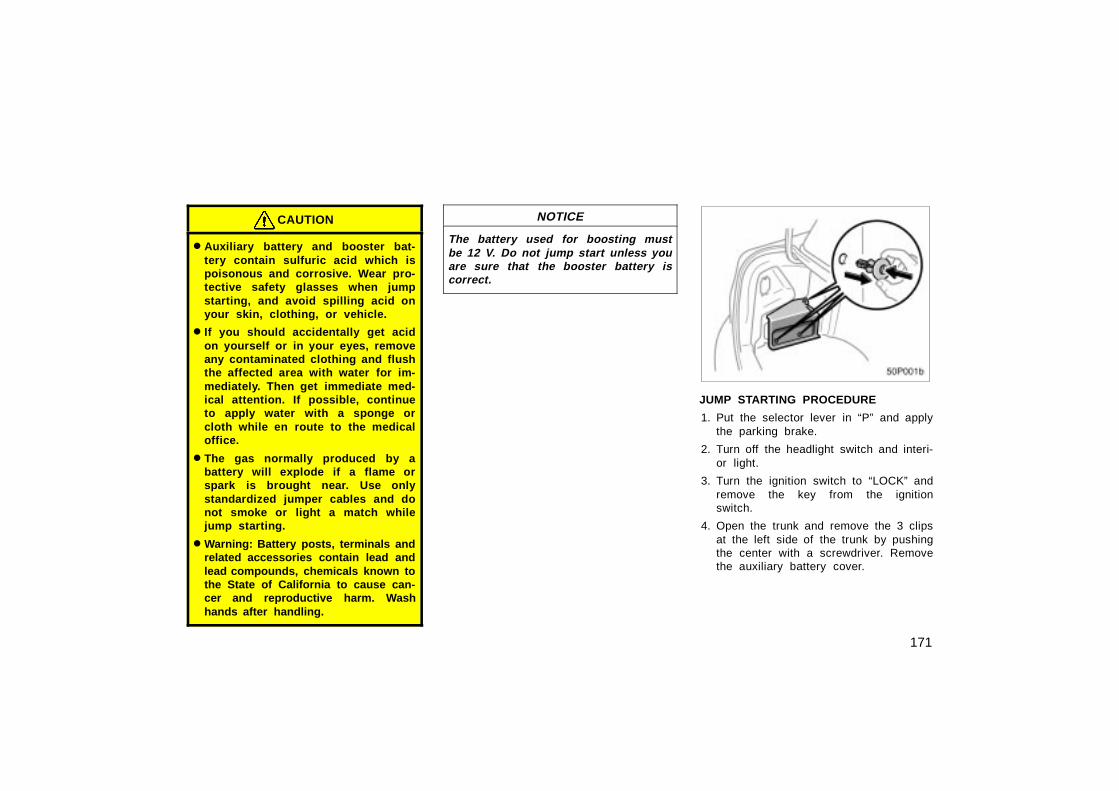
JUMP STARTING PROCEDURE
1. Put the selector lever in “P” and applythe parking brake.
2. Turn off the headlight switch and interi-or light.
3. Turn the ignition switch to “LOCK” andremove the key from the ignitionswitch.
4. Open the trunk and remove the 3 clipsat the left side of the trunk by pushingthe center with a screwdriver. Removethe auxiliary battery cover.
172
50p002
5. Remove the positive terminal cover ofthe auxiliary battery.
6. If the booster battery is installed inanother vehicle, make sure the ve-hicles are not touching. Turn off allunnecessary lights and accessories.
7. If required, remove all the vent plugsfrom the booster batteries. Lay a clothover the open vents on the batteries.(This helps reduce the explosion haz-ard, personal injuries and burns.)
8. If the engine in the vehicle with thebooster battery is not running, start itand let it run for a few minutes. Duringjump starting, run the engine at about2000 rpm with the accelerator pedallightly depressed.
50p044b
Dischargedbattery
Boosterbattery
Positive terminal (“+” mark)
Jumpercable
Positive terminal (“+” mark)
9. Connect the jumper cables in the ordera, b, c, d.
a. Connect the clamp of the positive(red) jumper cable to the positive(+) terminal on the discharged bat-tery.
b. Connect the clamp at the other endof the positive (red) jumper cable tothe positive (+) terminal on thebooster battery.
173
50p045b
Boosterbattery
Negative terminal (“–” mark)
Jumpercable
Dischargedbattery
c. Connect the clamp of the negative(black) jumper cable to the negative(–) terminal on the booster battery.
d. Connect the clamp at the other endof the negative (black) jumper cableto a solid, stationary, unpainted, me-tallic point of the vehicle with thedischarged battery.
The recommended connecting point isshown in the following illustrations:
50p043a
Connecting point
CAUTION
When making the connections, toavoid serious injury, do not lean overthe battery or accidentally let thejumper cables or clamps touch any-thing except the correct battery termi-nals or the ground.
10. Start the hybrid system. Make sure the“READY” light is on. If the hybrid ve-hicle battery warning light comes on inthe multi–information display, the hybridvehicle battery is also discharged. Con-tact your Toyota dealer.
11. Carefully disconnect the cables in theexact reverse order: the negative cableand then the positive cable.
12. Carefully dispose of the battery covercloths—they may now contain sulfuricacid.
13. If removed, replace all the battery ventplugs.
If the cause of your auxiliary battery dis-charging is not apparent (for example,lights left on), you should have it checkedat your Toyota dealer.
174
If your hybrid system stalls while driving...
1. Reduce your speed gradually, keepinga straight line. Move cautiously off theroad to a safe place.
2. Turn on your emergency flashers.
3. Turn the ignition switch to ”OFF” posi-tion, and try starting the hybrid systemagain.
If the hybrid system will not start, see “Ifyour vehicle will not start” on page 170.
CAUTION
If the hybrid system is not operating,the power assist for the brakes andsteering will not work so steering andbraking will be much harder than usu-al.
If your high coolant temperature warn-ing light comes on, if you experience aloss of power, or if you hear a loudknocking or pinging noise, the hybridsystem has probably overheated. Youshould follow this procedure...
1. Pull safely off the road, stop the ve-hicle and turn on your emergencyflashers. Put the transmission in “P”and apply the parking brake. Turn offthe air conditioning if it is being used.
2. If coolant or steam is boiling out of theradiator or reservoir, stop the hybridsystem. Wait until the steam subsidesbefore opening the hood. If there is nocoolant boiling over or steam, leave thehybrid system running and make surethe electric cooling fan is operating. Ifit is not, turn the ignition off.
CAUTION
To help avoid personal injury, keepthe hood closed until there is nosteam. Escaping steam or coolant isa sign of very high pressure.
3. Look for obvious coolant leaks from theradiator, hoses, and under the vehicle.However, note that water draining fromthe air conditioning is normal if it hasbeen used.
CAUTION
When the hybrid system is running,keep hands and clothing away fromthe moving fan and engine drivebelts.
4. If the coolant is leaking, stop the hy-brid system immediately. Call a Toyotadealer for assistance.
5. If there are no obvious leaks, checkthe coolant reservoir. If it is dry, addcoolant to the reservoir while the hy-brid system is running. Fill it about halffull.
CAUTION
Do not attempt to remove the radiatorcap when the hybrid system and ra-diator are hot. Serious injury couldresult from scalding hot fluid andsteam blown out under pressure.
If your hybrid system stallswhile driving130. 131.If your vehicle overheats
175
6. After the coolant temperature hascooled to normal, again check the cool-ant level in the reservoir. If necessary,bring it up to half full again. Seriouscoolant loss indicates a leak in thesystem. You should have it checked assoon as possible at your Toyota dealer.
1. Reduce your speed gradually, keepinga straight line. Move cautiously off theroad to a safe place well away fromthe traffic. Avoid stopping on the centerdivider of a highway. Park on a levelspot with firm ground.
2. Stop the hybrid system and turn onyour emergency flashers.
3. Firmly set the parking brake and putthe transmission in “P”.
4. Have everyone get out of the vehicleon the side away from traffic.
5. Read the following instructions thor-oughly.
CAUTION
When jacking, be sure to observe thefollowing to reduce the possibility ofpersonal injury:
� Follow jacking instructions.
� Do not put any part of your bodyunder a vehicle supported by ajack. Personal injury may occur.
� Do not start or run the hybrid sys-tem while your vehicle is supportedby the jack.
� Stop the vehicle at a level firmground, firmly set the parking brakeand put the transmission in “P”.Block the wheel diagonally oppositeto the one being changed if neces-sary.
� Make sure to set the jack properlyin the jack point. Raising the ve-hicle with jack improperly posi-tioned will damage the vehicle ormay allow the vehicle to fall off thejack and cause personal injury.
� Never get under the vehicle whenthe vehicle is supported by the jackalone.
� Use the jack only for lifting yourvehicle during wheel changing.
� Do not raise the vehicle with some-one in the vehicle.
� When raising the vehicle, do notput an object on or under the jack.
� Raise the vehicle only high enoughto remove and change the tire.
132.If you have a flat tire—
176
NOTICE
Do not continue driving with a de-flated tire. Driving even a short dis-tance can damage a tire and wheelbeyond repair.
50p007a
Compact spare tire
The compact spare tire is designed fortemporary emergency use only.
The compact spare tire is identified by thedistinctive wheel design and color andspecial wording “TEMPORARY USE ONLY”molded into the side wall of the tire.
The standard tire should be repaired andreplaced as soon as possible.
The compact spare tire saves space inyour luggage compartment, and its lighterweight helps to improve fuel economy andpermits easier installation in case of a flattire.
The compact spare tire can be used manytimes, if necessary. It has tread life of upto 4800 km (3000 miles) depending onroad conditions and your driving habits.When tread wear indicators appear on thetire, replace the tire.
See also the tire section on page 220 inSection 8–2 for details on the tread wearindicators and other service information.
CAUTION
� The compact spare tire was de-signed especially for your Toyota.Do not use it on any other vehicle.
� Do not use more than one compactspare tire at the same time.
� Do not exceed 80 km/h (50 mph)when driving with the compactspare tire.
Your ground clearance is reducedwhen the compact spare tire isinstalled so avoid driving over ob-stacles and drive slowly on rough,unpaved roads and speed bumps.Also, do not attempt to go through anautomatic car wash as the vehiclemay get caught, resulting in damage.
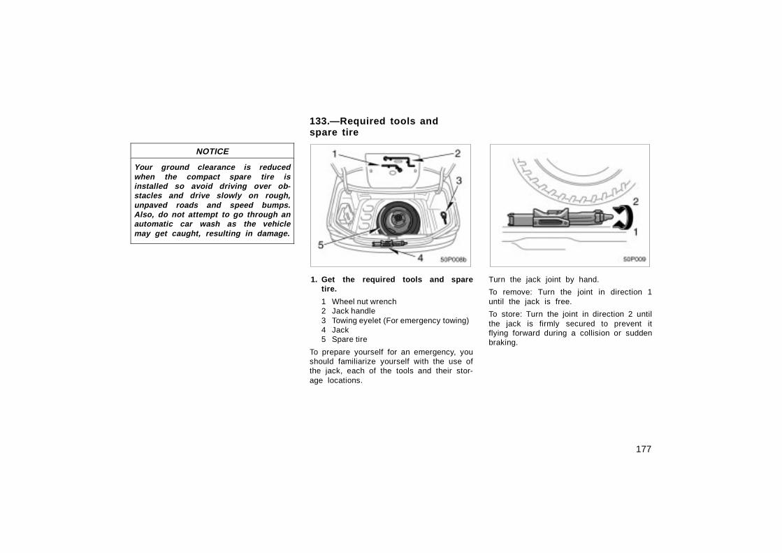
To prepare yourself for an emergency, youshould familiarize yourself with the use ofthe jack, each of the tools and their stor-age locations.
50p009
Turn the jack joint by hand.
To remove: Turn the joint in direction 1until the jack is free.
To store: Turn the joint in direction 2 untilthe jack is firmly secured to prevent itflying forward during a collision or suddenbraking.
133.—Required tools andspare tire
178
50p010d
To remove the spare tire:
1. Raise the luggage compartment floor.
2. Loosen the bolt with spacer and re-move it.
Then take the spare tire out of the ve-hicle.
When storing the spare tire, put it in placewith the outer side of the wheel facing up.Then secure the tire by repeating theabove removal steps in reverse order toprevent it from flying forward during acollision or sudden braking.
50p011a
2. Block the wheel diagonally oppositethe flat tire to keep the vehicle fromrolling when it is j acked up.
When chocking the wheel, place a wheelblock from the front for the front wheelsor from the rear for the rear wheels.
50p013b
3. Loosen all the wheel nuts.
Always loosen the wheel nuts before rais-ing the vehicle.
Turn the wheel nuts counterclockwise toloosen them. To get maximum leverage, fitthe wrench to the nut so that the handleis on the right side, as shown above.Grab the wrench near the end of the han-dle and pull up on the handle. Be carefulthat the wrench does not slip off the nut.
Do not remove the nuts yet—just unscrewthem about one–half turn.
—Blocking the wheel —Loosening wheel nuts
179
CAUTION
Never use oil or grease on the boltsor nuts. The nuts may loosen and thewheels may fall off, which couldcause a serious accident. 50p014d
4. Position the jack at the jack pointsas shown.
Make sure the jack is positioned on alevel and solid place.
50p015b
5. After making sure no one is in thevehicle, raise it high enough so thatthe spare tire can be installed.
Remember you will need more groundclearance when putting on the spare tirethan when removing the flat tire.
To raise the vehicle, insert the jack handleinto the jack (it is a loose fit) and turn itclockwise. As the jack touches the vehicleand begins to lift, double–check that it isproperly positioned.
—Positioning the jack —Raising your vehicle
180
CAUTION
Never get under the vehicle when thevehicle is supported by the jackalone.
50p016
6. Remove the wheel nuts and changetires.
Lift the flat tire straight off and put itaside.
Roll the spare wheel into position andalign the holes in the wheel with the bolts.Then lift up the wheel and get at least thetop bolt started through its hole. Wigglethe tire and press it back over the otherbolts.
50p017b
Before putting on wheels, remove any cor-rosion on the mounting surfaces with awire brush or such. Installation of wheelswithout good metal–to–metal contact at themounting surface can cause wheel nuts toloosen and eventually cause a wheel tocome off while driving.
—Changing wheels
181
50p018b
7. Reinstall all the wheel nuts fingertight.
Reinstall the wheel nuts (tapered end in-ward) and tighten them as much as youcan by hand. Press back on the tire andsee if you can tighten them more.
CAUTION
Never use oil or grease on the boltsor nuts. Doing so may lead to over-tightening the nuts and damaging thebolts. The nuts may loosen and thewheels may fall off, which couldcause a serious accident. If there isoil or grease on any bolt or nut,clean it.
50p019a
8. Lower the vehicle completely andtighten the wheel nuts.
Turn the jack handle counterclockwise tolower the vehicle.
Use only the wheel nut wrench to tightenthe nuts. Do not use other tools or anyadditional leverage other than your hands,such as a hammer, pipe or your foot.Make sure the wrench is securely en-gaged over the nut.
Tighten each nut a little at a time in theorder shown. Repeat the process until allthe nuts are tight.
—Reinstalling wheel nuts —Lowering your vehicle
182
CAUTION
� When lowering the vehicle, makesure all portions of your body andall other persons around will not beinjured as the vehicle is lowered tothe ground.
� Have the wheel nuts tightened bytorque wrench at 103 N·m (10.5kgf·lbf), as soon as possible afterchanging wheels. Otherwise, thenuts may loosen and the wheelsmay fall off, which could cause aserious accident.
9. Check the air pressure of the re-placed tire.
Adjust the air pressure to the specificationdesignated on page 241 in Section 9. Ifthe pressure is lower than specified, driveslowly to the nearest Toyota dealer and fillto the correct pressure.
Do not forget to reinstall the tire inflationvalve cap as dirt and moisture could getinto the valve core and possibly cause airleakage. If the cap is missing, have a newone put on as soon as possible.
10. Restow all the tools, jack and flattire securely.
As soon as possible after changingwheels, tighten the wheel nuts to thetorque specified on page 241 in Section9 with a torque wrench. Have a technicianrepair the flat tire and replace the sparetire with it.
CAUTION
Before driving, make sure all thetools, jack and flat tire are securelyin place in their storage location toreduce the possibility of personal in-jury during a collision or s uddenbraking.
50p021
(a) Towing with wheel lift type truck——From front
—From rear
(b) Using flat bed truck
—After changing wheelsIf your vehicle needs to betowed—134.
183
If towing is necessary, we recommendyou to have it done by your Toyotadealer or a commercial tow truck ser-vice. In consultation with them, haveyour vehicle towed using either (a) or(b).
Only when you cannot receive a towingservice from a Toyota dealer or com-mercial tow truck service, tow your ve-hicle carefully in accordance with theinstructions given in “—Emergency tow-ing” on page 184 in this Section.
Proper equipment will help ensure thatyour vehicle is not damaged while beingtowed. Commercial operators are generallyaware of the state/provincial and locallaws pertaining to towing.
Your vehicle can be damaged if it istowed incorrectly. Although most operatorsknow the correct procedure, it is possibleto make a mistake. To avoid damage toyour vehicle, make sure the following pre-cautions are observed. If necessary, showthis page to the tow truck driver.
TOWING PRECAUTIONS:
Use a safety chain system for all towing,and abide by the state/provincial and locallaws. The wheels and axle on the groundmust be in good condition. If they aredamaged, use a towing dolly.
(a) Towing with wheel lift type truck
From front —Release the parking brake.
NOTICE
When lifting wheels, take care to en-sure adequate ground clearance fortowing at the opposite end of theraised vehicle. Otherwise, the under-body of the towed vehicle will bedamaged during towing.
From rear —Use a towing dolly under thefront wheels.
NOTICE
Never tow a vehicle from the rearwith the front wheels on the ground,as this may cause serious damage tothe transmission.
(b) Using flat bed truck
50p022a
(c) Towing with sling type truck
(c) Towing with sling type truck
NOTICE
Do not tow with sling type truck, ei-ther from the front or rear. This maycause body damage.
184
50p035a
Front
50p028b
Rear
If towing is necessary, we recommendyou to have it done by your Toyotadealer or a commercial tow truck ser-vice.
If towing service is not available in anemergency, your vehicle may be tempo-rarily towed by a cable or chain se-cured to emergency towing eyelet in-side of front bumper. Use extremecaution when towing vehicles.
The front towing eyelet is provided in thetrunk. (For the front towing eyelet storagelocation, see “—Required tools and sparetire” on page 177.)
NOTICE
Only use specified towing eyelet;otherwise your vehicle may be dam-aged.
A driver must be in the vehicle to steerit and operate the brakes.
Towing in this manner may be done onlyon hard–surfaced roads for a short dis-tance and at low speeds. Also, thewheels, axles, drive train, steering andbrakes must all be in good condition.
CAUTION
� Use extreme caution when towingvehicles. Avoid sudden starts or er-ratic driving maneuvers whichwould place excessive stress on theemergency towing eyelet and towingcable or chain. The eyelet and tow-ing cable or chain may break andcause serious injury or damage.
� In case of installing the front eyeleton the vehicle, be sure to tightenin the front eyelet securely. If thetightening is loose, it may come offwhen towing and result in death orserious injury to the passenger inthe front vehicle or damage to thatvehicle.
NOTICE
Use only a cable or chain specificallyintended for use in towing vehicles.Securely fasten the cable or chain tothe towing eyelet provided.
Before towing, release the parking brakeand put the selector lever in “N”. The keymust be in “ACC” (hybrid system off) or“ON” (hybrid system on).
135.—Emergency towing
185
CAUTION
If the hybrid system is not running,the power assist for the brakes andsteering will not work so steering andbraking will be much harder than usu-al. 50p046
1. Remove the front towing eyelet asshown in the illustration.
50p047
2. Secure the front towing eyelet to thehole on the bumper by turning it clock-wise.
—Installing front towing eyelet
186
50p048
3. Tighten the front towing eyelet securelyby a wheel nut wrench.
CAUTION
When installing the eyelet on the ve-hicle, be sure to tighten the fronteyelet securely. If the tightening isloose, it may come off when beingtowed and result in death or seriousinjury.
50p026b
If you cannot shift the selector leverout of “P” position to other positionseven though the brake pedal is de-pressed, use the shift lock override but-ton as follows:
1. Turn the ignition key to “LOCK”position. Make sure the parkingbrake is applied.
2. Pry up the cover with a flat–bladedscrewdriver or equivalent.
50p027b
3. Insert your finger into the hole topush down the shift lock overridebutton. You can shift out of “P”position only while pushing the but-ton.
4. Shift into “N” position.
5. Insert the cover.
6. Start the hybrid system. For yoursafety, keep the brake pedal de-pressed.
Be sure to have the system checked byyour Toyota dealer as soon as possible.
If you cannot shift runningmode selector lever136.
187
You can purchase a new key at yourToyota dealer if you can give them thekey number and master key.
Even if you lose only one key, contactyour Toyota dealer to make a new key. Ifyou lose all your master keys, you cannotmake new keys; the whole hybrid vehicleimmobiliser system must be replaced.
See the suggestion given in “Keys” onpage 18 in Section 2–1.
If your keys are locked in the vehicle andyou cannot get a duplicate, many Toyotadealers can still open the door for you,using their special tools. If you mustbreak a window to get in, we suggestbreaking the smallest side window be-cause it is the least expensive to replace.Be extremely cautious to avoid cuts fromthe glass.
You can purchase a new wireless re-mote control transmitter at your Toyotadealer.
Have the registered identification numbersof your transmitters deleted from your ve-hicle by your Toyota dealer as soon aspossible to avoid the possibility of theft oran accident. Then, have the identificationnumber of your new transmitter registered.At the same time, you must bring all ofthe remaining transmitters to have themregistered again as well.
You can use the wireless remote controlsystem with the new transmitter. Contactyour Toyota dealer for detailed information.
137.If you lose your keysIf you lose your wirelessremote control transmitter138.
Toyota, through its diligent research, de-sign and use of the most advancedtechnology available, has done its part tohelp prevent corrosion and has providedyou with the finest quality vehicleconstruction. Now, it is up to you. Propercare of your Toyota can help ensure long–term corrosion prevention.
The most common causes of corrosionto your vehicle are:
� The accumulation of road salt, dirt andmoisture in hard–to–reach areas underthe vehicle.
� Chipping of paint, or undercoatingcaused by minor accidents or bystones and gravel.
Care is especially important if you livein particular areas or operate your ve-hicle under certain environmental condi-tions:
� Road salt or dust control chemicals willaccelerate corrosion, as will the pres-ence of salt in the air near the sea–coast or in areas of industrial pollution.
� High humidity accelerates corrosion es-pecially when temperatures range justabove the freezing point.
� Wetness or dampness to certain partsof your vehicle for an extended periodof time, may cause corrosion eventhough other parts of the vehicle maybe dry.
� High ambient temperatures can causecorrosion to those components of thevehicle which are prevented fromquick–drying due to lack of proper ven-tilation.
The above signifies the necessity to keepyour vehicle, particularly the underside, asclean as possible and to repair any dam-age to paint or protective coatings assoon as possible.
To help prevent corrosion on yourToyota, follow these guidelines:
Wash your vehicle frequently. It is, ofcourse, necessary to keep your vehicleclean by regular washing, but to preventcorrosion, the following points should beobserved:
� If you drive on salted roads in thewinter or if you live near the ocean,you should hose off the undercarriageat least once a month to minimize cor-rosion.
� Pay particular attention to the vehicle’sunderside and wheel housings as it isdifficult to see all the mud and dirt. Itwill do more harm than good to simplywet the mud and debris without remov-ing them. The lower edge of doors,rocker panels and frame members havedrain holes which should not be al-lowed to clog with dirt as trapped wa-ter in these areas can cause corrosion.
� Wash the underside of the vehicle thor-oughly when winter is over.
See “Washing and waxing your Toyota” formore tips.
Check the condition of your vehicle’spaint and trim. If you find any chips orscratches in the paint, touch them up im-mediately to prevent corrosion from start-ing. If the chips or scratches have gonethrough the bare metal, have a qualifiedbody shop make the repair.
Protecting your Toyota fromcorrosion140.
191
Check the interior of your vehicle. Wa-ter and dirt can accumulate under thefloor mats and could cause corrosion. Oc-casionally check under the mats to makesure the area is dry. Be particularly care-ful when transporting chemicals, cleans-ers, fertilizers, salt, etc.; these should betransported in proper containers. If a spillor leak should occur, immediately cleanand dry the area.
Keep your vehicle in a well ventilatedgarage or a roofed place. Do not parkyour vehicle in a damp, poorly venti-lated garage. If you wash your vehicle inthe garage, or if you drive it in coveredwith water or snow, your garage may beso damp it will cause corrosion. Even ifyour garage is heated, a wet vehicle cancorrode if the ventilation is poor.
60p001b
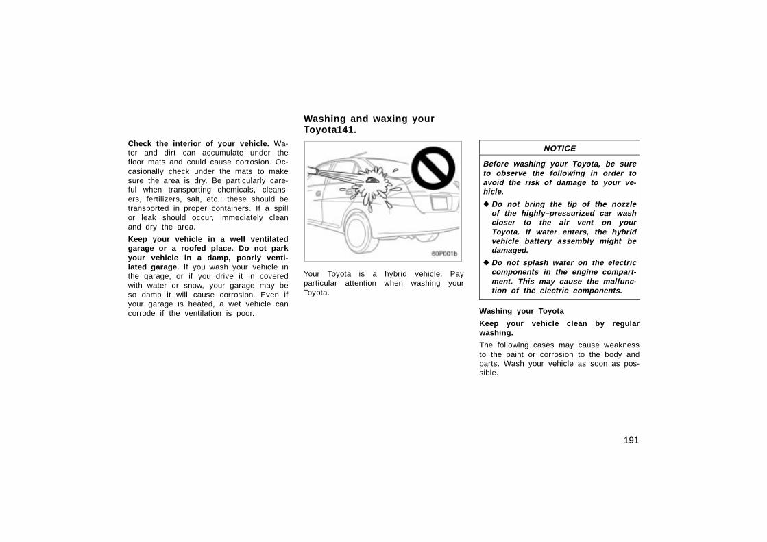
Your Toyota is a hybrid vehicle. Payparticular attention when washing yourToyota.
NOTICE
Before washing your Toyota, be sureto observe the following in order toavoid the risk of damage to your ve-hicle.
� Do not bring the tip of the nozzleof the highly–pressurized car washcloser to the air vent on yourToyota. If water enters, the hybridvehicle battery assembly might bedamaged.
� Do not splash water on the electriccomponents in the engine compart-ment. This may cause the malfunc-tion of the electric components.
Washing your Toyota
Keep your vehicle clean by regularwashing.
The following cases may cause weaknessto the paint or corrosion to the body andparts. Wash your vehicle as soon as pos-sible.
Washing and waxing your Toyota141.
192
� When driving in a coastal area
� When driving on a road sprinkled withantifreeze
� When having coal tar, tree sap, birddroppings and carcass of an insect
� When driving in the areas where thereare a lot of smoke, soot, dust, irondust and chemical substance
� When the vehicle becomes remarkablydirty with dust and mud
Hand–washing your Toyota
Work in the shade and wait until thevehicle body is not hot to the touch.
CAUTION
When cleaning under floor or chassis,be careful not to injure your hands.
1. Rinse off loose dirt with a hose. Re-move any mud or road salt from theunderside of the vehicle or in thewheel wells.
2. Wash with a mild car–wash soap,mixed according to the manufacturer’sinstructions. Use a soft cotton mitt andkeep it wet by dipping it frequently intothe wash water. Do not rub hard—letthe soap and water remove the dirt.
Plastic wheel ornaments: The plasticwheel ornaments are damaged easily byorganic substances. If any organic sub-stances splashes an ornament, be sure towash it off with water and check if theornament is damaged.
CAUTION
Do not attach the heavily damagedplastic wheel ornament. It may fly offthe wheel and cause accidents whilethe vehicle is moving.
Aluminum wheels: Use only a mild soapor neutral detergent.
Plastic bumpers: Wash carefully. Do notscrub with abrasive cleaners. The bumperfaces are soft.
Road tar: Remove with turpentine orcleaners that are marked safe for paintedsurfaces.
NOTICE
Do not use organic substances (gaso-line kerosene, benzine or strong sol-vents) which may be toxic or causedamage.
3. Rinse thoroughly—dried soap cancause streaking. In hot weather youmay need to rinse each section rightafter you wash it.
4. To prevent water spots, dry the vehicleusing a clean soft cotton towel. Do notrub or press hard—you might scratchthe paint.
Automatic car wash
Your vehicle may be washed in an auto-matic car wash, but remember that thepaint can be scratched by some type ofbrushes, unfiltered washing water, or thewashing process itself. Scratching reducespaint durability and gloss, especially ondarker colors. The manager of the carwash should be able to advise you wheth-er the process is safe for the paint onyour vehicle.
193
NOTICE
To prevent damage to the antenna,make sure to remove it before drivingyour Toyota through an automatic carwash.
Waxing your Toyota
Polishing and waxing is recommendedto maintain the original beauty of yourToyota’s finish.
Once a month or if the vehicle surfacedoes not repel water well, apply wax.
1. Always wash and dry the vehicle be-fore you begin waxing, even if you areusing a combined cleaner and wax.
2. Use a good quality polish and wax. Ifthe finish has become extremely weath-ered, use a car–cleaning polish, fol-lowed by a separate wax. Carefully fol-low the manufacturer’s instructions andprecautions. Be sure to polish and waxthe chrome trim as well as the paint.
3. Wax the vehicle again when waterdoes not bead but remains on the sur-face in large patches.
NOTICE
Always remove the plastic bumpers ifyour vehicle is re–painted and placedin a high heat paint waxing booth.High temperatures could damage thebumpers.
CAUTION
� Do not wash the vehicle floor withwater, or allow water to get ontothe floor when cleaning the vehicleinterior or exterior. Water may getinto audio components or otherelectrical components above or un-der the floor carpet (or mat) andcause fire or malfunction; and itmay cause body corrosion.
� Vehicles with side airbags:Be careful not to splash water orspill liquid on the floor. This mayprevent the side airbags from acti-vating correctly, resulting in seriousinjury.
Vinyl interior
The vinyl upholstery may be easilycleaned with a mild soap or detergentand water.
142.Cleaning the interior
194
First vacuum over the upholstery to re-move loose dirt. Then, using a sponge orsoft cloth, apply the soap solution to thevinyl. After allowing it to soak in for a fewminutes to loosen the dirt, remove the dirtand wipe off the soap with a clean dampcloth. If all the dirt does not come off,repeat the procedure. Commercial foam-ing–type vinyl cleaners are also availablewhich work well. Follow the manufacturer’sinstructions.
NOTICE
Do not use solvent, thinner, gasolineor window cleaner on the interior.
Carpets
Use a good foam–type shampoo toclean the carpets.
Begin by vacuuming thoroughly to removeas much dirt as possible. Several types offoam cleaners are available; some are inaerosol cans and others are powders orliquids which you mix with water to pro-duce a foam. To shampoo the carpets,use a sponge or brush to apply the foam.Rub in overlapping circles.
Do not apply water—the best results areobtained by keeping the carpet as dry aspossible. Read the shampoo instructionsand follow them closely.
Seat belts
The seat belts may be cleaned withmild soap and water or with lukewarmwater.
Use a cloth or sponge. As you are clean-ing, check the belts for excessive wear,fraying, or cuts.
NOTICE
� Do not use dye or bleach on thebelts–it may weaken them.
� Do not use the belts until they be-come dry.
Windows
The windows may be cleaned with anyhousehold window cleaner.
NOTICE
When cleaning the inside of the win-dows, be careful not to scratch ordamage the heater wires on the rearwindow.
Air conditioning control panel, car au-dio, instrument panel, console panel,and switches
Use a soft damp cloth for cleaning.
Soak a clean soft cloth in water or luke-warm water then lightly wipe off dirt.
195
NOTICE
� Do not use organic substances (sol-vents, kerosene, alcohol, gasoline,etc.) or alkaline or acidic solutions.These chemicals can cause discol-oring, staining or peeling of thesurface.
� If you use cleaners or polishingagents, make sure their ingredientsdo not include the substances men-tioned above.
� If you use a liquid car freshener, donot apply the liquid onto the ve-hicle’s interior surfaces. It may con-tain the ingredients mentionedabove. Immediately clean any spillusing the method mentioned above.
Leather interior
The leather upholstery may be cleanedwith neutral detergent for wool.
Remove dirt using a soft cloth dampenedwith 5% solution of neutral detergent forwool. Then thoroughly wipe off all tracesof detergent with a clean damp cloth.
After cleaning or whenever any part of theleather gets wet, dry with a soft cleancloth. Allow the leather to dry in a venti-lated shaded area.
NOTICE
� If a stain should fail to come outwith a neutral detergent, apply acleaner that does not contain anorganic solvent.
� Never use organic substances suchas benzine, alcohol or gasoline, oralkaline or acid solutions for clean-ing the leather as these couldcause discoloring.
� Use of a nylon brush or syntheticfiber cloth, etc. may scratch thefine grained surface of the leather.
� Mildew may develop on soiled leath-er upholstery. Be especially carefulto avoid oil spots. Try to keep yourupholstery always clean.
� Long exposure to direct sunlightmay cause the leather surface toharden and shrink. Keep your ve-hicle in a shaded area, especially inthe summer.
� The interior of your vehicle is aptto heat up on hot summer days, soavoid placing on the upholsteryitems made of vinyl or plastic orcontaining wax as these tend tostick to leather when warm.
� Improper cleaning of the leather up-holstery could result in discolor-ation or staining.
If you have any questions about thecleaning of your Toyota, your localToyota dealer will be pleased to answerthem.
For scheduled maintenance information, please refer to the”Scheduled Maintenance Guide” or ”Owner’s Manual Supplement”.
SECTION 7
198
144.Maintenance requirementsYour Toyota vehicle has been designed forfewer maintenance requirements with long-er service intervals to save both your timeand money. However, each regular mainte-nance, as well as day–to–day care, ismore important than ever before to ensuresmooth, trouble–free, safe, and economicaldriving.
It is the owner’s responsibility to makesure the specified maintenance, includinggeneral maintenance service, is performed.Note that both the new vehicle andemission control system warranties specifythat proper maintenance and care must beperformed. See ”Owner’s WarrantyInformation Booklet” or ”Owner’s ManualSupplement” for complete warrantyinformation.
General maintenance
General maintenance items are those day–to–day care practices that are important toyour vehicle for proper operation. It is theowner’s responsibility to ensure that thegeneral maintenance items are performedregularly.
These checks or inspections can be doneeither by yourself or a qualified technician,or if you prefer, your Toyota dealer will bepleased to do them at a nominal cost.
Scheduled maintenance
The scheduled maintenance items listed inthe ”Scheduled Maintenance Guide” or”Owner’s Manual Supplement” are thoserequired to be serviced at regular inter-vals.
For details of your maintenance schedule,read the ”Scheduled Maintenance Guide”or ”Owner’s Manual Supplement”.
It is recommended that only genuineToyota parts be used for maintenanceor for the repair of the emission con-trol system.
The owner may elect to use non–Toyotasupplied parts for replacement pur-poses without invalidating the emissioncontrol system warranty. However, useof replacement parts which are not ofequivalent quality may impair the effec-tiveness of the emission control sys-tems.
You may also elect to have mainte-nance, replacement, or repair of theemission control devices and systemperformed by any automotive repair es-tablishment or individual without invali-dating this warranty. See ”Owner’s War-ranty Information Booklet” or ”Owner’sManual Supplement” for complete war-ranty information.
Where to go for service?
Toyota technicians are well–trained spe-cialists and are kept up to date with thelatest service information through technicalbulletins, service tips, and in–dealershiptraining programs. They learn to work onToyotas before they work on your vehicle,rather than while they are working on it.
You can be confident that your Toyotadealer’s service department performs thebest job to meet the maintenance require-ments on your vehicle–reliably and eco-nomically.
Your copy of the repair order is proof thatall required maintenance has been per-formed for warranty coverage. And if anyproblems should arise with your vehiclewhile under warranty, your Toyota dealerwill promptly take care of it. Again, besure to keep a copy of the repair orderfor any service performed on your Toyota.
What about do–it–yourself maintenance?
Many of the maintenance items are easyto do yourself if you have a little mechani-cal ability and a few basic automotivetools. Simple instructions for how to per-form them are presented in Section 8.
199
If you are a skilled do–it–yourselfmechanic, the Toyota service manuals arerecommended. Please be aware thatdo–it–yourself maintenance can affect yourwarranty coverage. See ”Owner’s WarrantyInformation Booklet” or ”Owner’s ManualSupplement” for the details.
145.General maintenanceListed below are the general maintenanceitems that should be performed as fre-quently as specified. In addition to check-ing the items listed, if you notice anyunusual noise, smell or vibration, youshould investigate the cause or take yourvehicle to your Toyota dealer or a quali-fied service shop immediately. It is recom-mended that any problem you notice bebrought to the attention of your dealer orthe qualified service shop for their advice.
CAUTION
Make these checks only where ade-quate ventilation can be obtained ifyou run the engine.
OUTSIDE THE VEHICLE
Items listed below should be performedfrom time to time, unless otherwisespecified.
Tire pressureCheck the pressure with a gauge everytwo weeks, or at least once a month. Seepage 219 in Section 8–2 for additionalinformation.
Tire surface and wheel nutsCheck the tires carefully for cuts, damageor excessive wear. See Section 8–2 foradditional information. When checking thetires, make sure no nuts are missing, andcheck the nuts for looseness. Tightenthem if necessary.
Tire rotationRotate the tires according to the mainte-nance schedule. (For scheduled mainte-nance information, please refer to the“Scheduled Maintenance Guide” or “Own-er’s Manual Supplement”.) See page 221in Section 8–2 for additional information.
Fluid leaksCheck underneath for leaking fuel, oil, wa-ter or other fluid after the vehicle hasbeen parked for a while. If you smell fuelfumes or notice any leak, have the causefound and corrected immediately.
Doors and engine hoodCheck that all doors and trunk operatesmoothly and all latches lock securely.Make sure the engine hood secondarylatch secures the hood from opening whenthe primary latch is released.
200
INSIDE THE VEHICLE
Items listed below should be checkedregularly, e.g. while performing periodicservices, cleaning the vehicle, etc.
LightsMake sure the headlights, stop lights, taillights, turn signal lights, and other lightsare all working. Check headlight aim.
Service reminder indicators and warningbuzzersCheck that all service reminder indicatorsand warning buzzers function properly.
Steering wheelBe alert for changes in steering condition,such as hard steering or strange noise.
SeatsCheck that all front seat controls such asseat adjusters, seatback recliner, etc. op-erate smoothly and that all latches locksecurely in any position. Check that thehead restraint move up and down smooth-ly and that the locks hold securely in anylatched position.
Seat beltsCheck that the seat belt system such asbuckles, retractors and anchors operateproperly and smoothly. Make sure the beltwebbing is not cut, frayed, worn or dam-aged.
Accelerator pedalCheck the pedal for smooth operation anduneven pedal effort or catching.
Brake pedalCheck the pedal for smooth operation andthat the pedal has the proper clearance.Check the brake booster function.
BrakesAt a safe place, check that the brakes donot pull to one side when applied.
Parking brakeCheck that the pedal has the proper traveland that, on a safe incline, your vehicleis held securely with only the parkingbrake applied.
Hybrid transaxle ”Park” mechanismCheck the lock release button of the se-lector lever for proper and smooth opera-tion. On a safe incline, check that yourvehicle is held securely with the selectorlever in ”P” position and all brakes re-leased.
IN THE ENGINE COMPARTMENT
Items listed below should be checkedfrom time to time, e.g. each time whenrefueling.
Washer fluidMake sure there is sufficient fluid in thetank. See page 229 in Section 8–3 foradditional information.
Coolant levelMake sure the coolant level is betweenthe ”FULL” and ”LOW” lines on the see–through reservoir when the hybrid systemis cold. See page 214 in Section 8–2 foradditional information.
Radiator, condenser and hosesCheck that the front of the radiator andcondenser are clean and not blocked withleaves, dirt, or insects. See page 216 inSection 8–2 for additional information.
201
Brake fluid levelMake sure the brake fluid level is correct.See page 216 in Section 8–2 for addition-al information.
Engine oil levelCheck the level on the dipstick with theengine turned off and the vehicle parkedon a level spot. See page 212 in Section8–2 for additional information.
Exhaust systemIf you notice any change in the sound ofthe exhaust or smell exhaust fumes, havethe cause located and corrected immedi-ately. (See “Engine exhaust cautions” onpage 152 in Section 3.)
Be on the alert for changes in perfor-mance, sounds, and visual tip–offs thatindicate service is needed. Some impor-tant clues are as follows:
� Engine missing, stumbling, or pinging
� Appreciable loss of power
� Strange engine noises
� A fluid leak under the vehicle (however,water dripping from the air conditioningafter use is normal.)
� Change in exhaust sound (This mayindicate a dangerous carbon monoxideleak. Drive with the windows open andhave the exhaust system checked im-mediately.)
� Vehicle pulls to one side when drivingstraight on a level road
� Strange noises related to suspensionmovement
� Loss of brake effectiveness; spongyfeeling brake pedal; pedal almosttouches floor; vehicle pulls to one sidewhen braking
� Coolant temperature continually higherthan normal
If you notice any of these clues, take yourvehicle to your Toyota dealer as soon aspossible. It probably needs adjustment orrepair.
CAUTION
Do not continue driving with the ve-hicle unchecked. It could result in se-rious vehicle damage and possiblypersonal injury.
146.Does your vehicle need repairing?
202
Some states have vehicle emission in-spection programs which include OBD(On–Board Diagnostics) checks.
The OBD system monitors the operationof the emission control system. When theOBD system determines that a problemexists somewhere in the emission controlsystem, the malfunction indicator lampcomes on. In this case, your vehicle maynot pass the I/M test and need to berepaired. Contact your Toyota dealer toservice the vehicle.
Even if the malfunction indicator lampdoes not come on, your vehicle may notpass the I/M test as readiness codeshave not been set in the OBD system.
Readiness codes are automatically setduring ordinary driving. However, when thebattery is disconnected or run down, thecodes are erased. Also, depending onyour driving habits, the codes may not becompletely set.
Also, if the malfunction indicator lamp hadcome on recently due to temporary mal-function such as a loose fuel tank cap,your vehicle may not pass the I/M test.
The malfunction indicator lamp will go offafter taking several driving trips, but theerror code in the OBD system will not becleared unless about 40 trips or more aretaken.
If your vehicle does not pass the I/M testand the malfunction indicator lamp doesnot come on, contact your Toyota dealerto prepare the vehicle for re–testing.
Valve clearance (engine cold), mm (in.):Intake 0.17—0.23 (0.007—0.009)Exhaust 0.27—0.33 (0.011—0.013)
Spark plug type:DENSO SK16R11NGK IFR5A11
Spark plug gap, mm (in.):1.1 (0.043)
178.Fuel
240
ENGINE LUBRICATION
Oil capacity (drain and refill), L (qt, lmp.qt.):
With filter 3.7 (3.9, 3.3)Without filter 3.4 (3.6, 3.0)
“Toyota Genuine Motor Oil” is filled in yourToyota vehicle. Use Toyota approved “ToyotaGenuine Motor Oil” or equivalent to satisfy thefollowing grade and viscosity.
Oil grade:
API grade SL “Energy–Conserving” orILSAC multigrade engine oil.
Recommended oil viscosity:
SAE 5W–30
oil008
Temperature range anticipated before nextoil change
Please contact your Toyota dealer for furtherdetails.
181.COOLING SYSTEM
Total capacity, L (qt., Imp. qt.):For gasoline engine 4.9 (5.2, 4.3)For electric motor and inverter and converter 2.6 (2.7, 2.3)
Coolant type:“Toyota Genuine Long Life Coolant” isfilled in your Toyota vehicle. In order toavoid technical problems, we stronglyrecommend using “Toyota Genuine LongLife Coolant” or equivalent.Please contact your Toyota dealer forfurther details.
With ethylene–glycol type coolant for aproper corrosion protection of aluminumcomponents
Do not use alcohol type antifreeze or plainwater alone.
AUXILIARY BATTERY
Open voltage at 20�C (68�F):12.6 – 12.8 V Fully charged12.2 – 12.4 V Half charged11.5 – 11.9 V Discharged
[Voltage that is checked 20 minutes afterthe key is removed with all the lightsturned off]
Charging rates: 3.5 A max.
241
HYBRID TRANSAXLE
Fluid capacity, L (qt., Imp. qt.):4.6 (4.9, 4.1)
Fluid type: “Toyota Genuine ATF Type T–IV” or equivalent
BRAKES
Minimum pedal clearance when depressedwith the force of 196 N (20 kgf, 44 lbf)with the traction motor running, mm (in.):
80 (3.15)
Pedal free play, mm (in.):1 – 6 (0.04 – 0.24)
Parking brake adjustment when depressedwith the force of 294 N (30 kgf, 66 lbf):
NOTE: For a complete information on tires(e.g. replacing tires or replacingwheels), see ”Checking tire pres-sure” through ”Aluminum wheelprecautions”, page 219 through224 in Section 8–2.
242
90p005a
Engine compartment
1. ABS NO.4 10 A: Anti–lock brake sys-tem
2. HTR NO.1 30 A: Air conditioning sys-tem
3. HTR NO.2 30 A: Air conditioning sys-tem
4. DRL 7.5 A: Daytime running light sys-tem
5. CDS FAN 30 A: Air conditioning sys-tem
6. HORN 10 A: Horn
7. HEAD HI (RH) (Vehicles with Daytimerunning light system only) 10 A:Right–hand headlight (high beam)
20. GAUGE 10 A: Gauge and meter, emer-gency flasher, rear window defogger,service reminder indicator and warningbuzzers, back–up light, power windowsystem, air conditioning system
If you believe that your vehicle hasa defect which could cause a crashor could cause injury or death, youshould immediately inform the Na-tional Highway Traffic Safety Ad-ministration (NHTSA) in addition tonotifying Toyota Motor Sales,U.S.A., Inc. (Toll–free:1–800–331–4331).
If NHTSA receives similar com-plaints, it may open an investiga-tion, and if it finds that a safety de-fect exists in a group of vehicles, itmay order a recall and remedycampaign. However, NHTSA cannotbecome involved in individual prob-lems between you, your dealer, orToyota Motor Sales, U.S.A., Inc.
To contact NHTSA, you may eithercall the Auto Safety Hotline toll–freeat 1–800–424–9393 (or 366–0123in Washington, D.C. area) or writeto: NHTSA, U.S. Department ofTransportation, Washington, D.C.20590. You can also obtain otherinformation about motor vehiclesafety from the Hotline.
Uniform tire quality grading186.This information has been prepared in ac-cordance with regulations issued by theNational Highway Traffic Safety Adminis-tration of the U.S. Department of Trans-portation. It provides the purchasers and/or prospective purchasers of Toyotavehicles with information on uniform tirequality grading.
Your Toyota dealer will help answer anyquestions you may have as you read thisinformation.
DOT quality grades—All passenger cartires must conform to Federal SafetyRequirements in addition to thesegrades. Quality grades can be foundwhere applicable on the tire sidewallbetween tread shoulder and maximumsection width. For example: Treadwear200 Traction AA Temperature A.
Reporting safety defects forU.S. owners185.
247
Tread wear— The tread wear grade is acomparative rating based on the wear rateof the tire when tested under controlledconditions on a specified government testcourse. For example, a tire graded 150would wear one and a half (1–1/2) timesas well on the government course as atire graded 100. The relative performanceof tires depends upon the actual condi-tions of their use, however, and may de-part significantly from the norm due tovariations in driving habits, service prac-tices and differences in road characteris-tics and climate.
Traction AA, A, B, C— The tractiongrades, from highest to lowest, are AA, A,B, and C, and they represent the tire’sability to stop on wet pavement as mea-sured under controlled conditions on spe-cified government test surfaces of asphaltand concrete. A tire marked C may havepoor traction performance.
Warning: The traction grade assigned tothis tire is based on braking (straightahead) traction tests and does not includecornering (turning) traction.
Temperature A, B, C— The temperaturegrades are A (the highest), B, and C,representing the tire’s resistance to thegeneration of heat and its ability to dissi-pate heat when tested under controlledconditions on a specified indoor laboratorytest wheel. Sustained high temperaturecan cause the material of the tire to de-generate and reduce tire life, and exces-sive temperature can lead to sudden tirefailure. The grade C corresponds to a lev-el of performance which all passenger cartires must meet under the Federal MotorVehicle Safety Standard No. 109. GradesB and A represent higher levels of perfor-mance on the laboratory test wheel thanthe minimum required by law.
Warning: The temperature grades for thistire are established for a tire that is prop-erly inflated and not overloaded. Exces-sive speed, underinflation, or excessiveloading, either separately or in combina-tion, can cause heat buildup and possibletire failure.
248
1
FEATURES ON NEW TOYOTA VEHICLE1.Overview of instruments and controls
Toyota hybrid system combines thegasoline engine and the electric motorpower to improve the fuel economylargely and minimize the emissions aswell as to provide higher power perfor-mance than the ordinary gasoline–pow-ered vehicles.
Depending on the driving condition, thevehicle runs on the best combination of;
� Gasoline engine power
� Electric motor power generated bythe gasoline engine
� Electric motor power of the hybridvehicle battery
Furthermore, the energy is effectively usedin the following ways:
� When stopping the vehicle, the gaso-line engine is automatically stopped.
� When decreasing the speed by apply-ing the brakes, electricity convertedfrom the turning force of the wheels isstored in the hybrid vehicle battery.(This is called regenerative brake.)
Since the battery is charged by thegasoline engine as needed, it does notrequire charging from the outside likean electric vehicle.
In this way, greatly improved fuel economyand reduced emissions are attained.
If you do not use the vehicle for a longtime (2 weeks or more), the hybrid ve-hicle battery and auxiliary battery will dis-charge and their condition is liable to de-cline. Therefore, in order to make up fordischarging, charge them once in every 2weeks for about 30 minutes by startingthe hybrid system with all electrical com-ponents turned off.
Basic operations are described below. Be-sides, Toyota hybrid system performs vari-ous controls depending on the operatingcondition, such as at the time of hybridsystem starting, at the time of chargingshould be required, at the time of the airconditioning is in use, etc.
When starting or backing up, etc., thegasoline engine efficiency worsens, sothe vehicle runs on electric power fromhybrid vehicle battery.
12p017a
Gasoline powerin use
During normal driving, the vehicle runsmainly on gasoline power. However, theelectric motor, using electric power gener-ated by the gasoline engine, makes up forany deficiency of gasoline power.
The vehicle controls the optimum ratio ofthe gasoline and electric power to helpsave energy more effectively.
12p018a
Electric and gasolinepower in use
When driving at full throttle, electricpower is further applied from the hybridvehicle battery. Vehicle performance impro-ves.
10
12p019a
Storing electric power
When decreasing speed or applying thebrakes, the turning force of the wheelsmakes the electric motor operate as agenerator and additional electricity isstored in the hybrid vehicle battery (regen-erative brake).
12p020a
Not in use
When stopping, the gasoline engine auto-matically shuts off.
12p030
Charging hybrid vehicle battery
When the hybrid vehicle battery power isinsufficient, the gasoline engine chargesthe hybrid vehicle battery. The system al-ways supplies electricity at a constant lev-el.
11
Turn the ignition key from “ON” to“START” with the running mode selectorlever in “P” position only. When the“READY” light flashes and stays on anda beep sounds after a few seconds, thehybrid system starts. (If the ambient tem-perature is low such as during winter con-ditions, it may take time until the“READY” light is on.) Being different fromordinary vehicles, you cannot start yourvehicle with the running mode selector le-ver in “N” position. (For details, see “Howto start the hybrid system—” on page 164in Section 4.)
Drive your vehicle with a smooth accel-eration and deceleration.
� When driving, energy is effectively re-covered through the regenerative brakeas the vehicle decelerates. However,for more efficient use, do not acceler-ate or decelerate your vehicle morethan necessary.
� By avoiding abrupt acceleration and de-celeration, the remaining capacity ofthe hybrid vehicle battery can be pre-served and it makes it possible to runthe vehicle utilizing the gasoline engineand the electric power from the hybridvehicle battery.
� The remaining capacity of the hybridvehicle battery can be confirmed onthe energy monitor screen of the multi–information display. See “Information”on 115 page in Section 2–6 for details.As the way in which you drive maydecrease the remaining capacity of thehybrid vehicle battery and reduce fueleconomy, drive your vehicle withoutabrupt acceleration or deceleration.
Use the “A/C” mode (with the “A/C”button only on) when you use the airconditioning.
� As the gasoline engine starts andstops automatically in this mode, eco-nomical driving with less emissions ispossible.
� In the “MAX” mode (with the “A/C” but-ton and “MAX” button on), the gasolineengine is frequently used. Use thismode only when you need to operatethe air conditioning fully such as whenyou should dehumidify or when you areunder a burning sun.
When parking, be sure to put the run-ning mode selector lever in “P” posi-tion. While driving, use “D” position.
� With the selector lever in “N” position,the gasoline engine operates but elec-tricity cannot be generated. Theconstant electrical power remaining inthe hybrid vehicle battery becomes in-sufficient and the battery will be dis-charged.
8.Starting your vehicle9.For efficient use of yourvehicle
12
� The hybrid system automatically con-trols the level of electrical power re-maining in the hybrid vehicle battery.With the selector lever in a positionother than “N”, electricity is generatedand charging occurs when the level ofelectrical power in the hybrid vehiclebattery decreases. It is unnecessary tocharge the hybrid vehicle battery fromoutside.
INFORMATION:
The gasoline engine starts and stopsautomatically. (It stops during a lowload driving, deceleration or when thevehicle stopped.)
If the “READY” light remains on, youcan start your vehicle using the electricmotor even with the gasoline enginestopped.
The gasoline engine may not stop auto-matically in the following conditions:
� During under gasoline engine warm–up
� During hybrid vehicle battery charg-ing
� When the air conditioning is used inthe “MAX” mode, the gasoline engineis frequently used.
If the output control warning light ( )comes on in the instrument cluster, thehybrid vehicle battery temperature islow or high, or the hybrid vehicle bat-tery capacity is decreased with the se-lector lever at “R” during driving. As itdoes not indicate the failure of the sys-tem, you can continue driving but avoidhard acceleration because the power isinsufficient (which is caused by the bat-tery power deterioration).
The vehicle runs in combination withthe gasoline and electric power. Payspecial attention to the following items.
Be careful of a high voltage and hightemperature.
Your vehicle is equipped with the orangecolored cables connected to the hybridvehicle battery which contain a high volt-age (about 300 V) and to other high volt-age parts.
CAUTION
Do not touch or come in contact withorange cables or battery terminals.Electric shock may cause serious in-jury or death. Read all caution labels.
A electric motor, coolant radiator andsome other parts reach high temperaturewhen you are driving. Caution labels areapplied to these parts. Carefully observethe instructions on these caution labels.
10.Precautions for use
13
CAUTION
Never remove or disassemble thehigh voltage parts, high voltagecables (orange color) and their con-nectors. It may cause death or seri-ous injury. 12p007d
Inverter unit
Hybrid vehicle battery
Serviceplug
High volt-age cables
Do not touch the service plug.
The service plug is installed in the leftside trim of the trunk. It is provided toshut out high voltage current of the hybridvehicle battery when the vehicle is inneed of repairs at a Toyota dealer.
CAUTION
� The shaded parts in the illustrationare subjected to a high voltage.
� Inappropriate handling may causean electric shock resulting in seri-ous injury or death. Never touchany item in shaded area.
Keep your hybrid vehicle’s driving char-acteristics in mind.
� As the vehicle runs with both the gaso-line engine and electric motor, you mayhear a motor sound coming from theengine compartment.
� When the ignition switch is turned toon or off, you may hear a sound com-ing from the hybrid vehicle battery inthe trunk. However, this does not indi-cate any trouble.
� If the “READY” light is on, you canstart even with the gasoline enginestopped.
� When the hybrid vehicle battery tem-perature is low or high, or the hybridvehicle battery capacity is decreasedwith the selector lever at “R” duringdriving, the output control warning lightcomes on and the output might be lim-ited for longer battery charge life.
� If the output control warning light is on,drive your vehicle without hard accel-eration. The output power will be limit-ed particularly when backing up.
14
� When you put the running mode selec-tor lever in “B” position and releaseyour foot from the accelerator pedal,engine braking will be applied. Howev-er, during the high speed driving youmay feel that deceleration by enginebraking is less than that of ordinaryvehicle.
Drive your vehicle without hard accel-eration if the output control warninglight ( ) is on.
The hybrid vehicle battery temperature islow or high, or the hybrid vehicle batterycapacity is decreased with the selectorlever at “R” during driving. If this occurs,the output control warning light comes on.If the output control warning light is on,the hybrid system output is limited. Driveyour vehicle without hard acceleration.
Vehicle performance might be reduced sig-nificantly especially when backing up.
Be sure to put the running mode selec-tor lever in “P” position when parking.
With the selector lever in “N” position, thehybrid vehicle battery assembly is notcharged, even if the gasoline engine isoperating. You cannot run your vehicle ifthe selector lever is left in “N” position fora long time because the hybrid vehiclebattery assembly will be discharged.
When you leave your vehicle, apply theparking brake with the running modeselector lever in “P” position and besure to remove the key and lock all thedoors.
When you leave the the ignition key in the“ACC” or “ON” position if the hybrid sys-tem is not operating, the hybrid systemmay not start because the auxiliary bat-tery will be discharged.
CAUTION
� When you leave your vehicle, besure to shut off the hybrid system.
� Be sure to put the running modeselector lever in “P” position be-cause the vehicle can start with the“READY” light on and the enginestopped (no engine sound andvibration). When the “READY” lightis on, if you leave your vehicle withthe running mode selector lever ina position other than “P” and “N”,the vehicle will creep and startabruptly with the accelerator pedalbeing depressed by mistake. It maycause death or serious injury.
12p008a
If the multi–information display showsa message, the master warning light( ) comes on in the instrument clus-ter. Read the message and follow theinstruction.
� When you leave your vehicle, or stopor park for a while, put the selectorlever in “P”.
� Charging is necessary. With the selec-tor lever in “N” position, charging willnot be applied. The electric generatoroperates in “P”, “D” or “B” position. Ifyou continue driving, put the selectorlever in “D” or “B” position and depressthe accelerator pedal. Do not leave itin “N” position. When driving in trafficjam, run in “D” position.
15
12p009c
Do not put the luggage on the packagetray behind the rear seatback.
� An air vent is provided on the packagetray behind the rear seatback to coolthe hybrid vehicle battery. If this ventis covered with something, the hybridvehicle battery will overheat resulting ina reduction of the output performanceof the hybrid system.
� Do not apply water or put foreign ob-jects over the air vent. Otherwise, itmay affect the hybrid vehicle batteryadversely and cause damage.
� You may hear a cooling fan noise fromthe air vent.
For vehicle repairs or maintenance, besure to consult your Toyota dealer.
If your vehicle is beyond repair becauseof accident or something, be sure toconsult your Toyota dealer.
As sealed Nickel–Metal hydride batteriesare used, be sure to consult your Toyotadealer when disposing of your vehicle.
CAUTION
If you are involved in an accident,follow these precautions.
� Move the vehicle to a safe placeand perform the followings to re-duce the risk of high voltage elec-tricity leakage.� Depress the brake pedal and put the
selector lever in “P” position.
� Apply the parking brake.
� Turn the ignition switch to “LOCK”and remove the key.
� If your vehicle has experienced ma-jor damage, you may get an electricshock. To prevent this, never touchthe high voltage parts (hybrid ve-hicle battery assembly, etc.) orcables (orange color) connectingthese parts. If some exposed elec-tric wiring is protruding inside oroutside of the vehicle, an electricshock may also occur. Never touchthem.
� If the fluid leaks or gets in somepart of the vehicle, never touch itbecause it may be electrolyte(strong alkali) from the hybrid ve-hicle battery. If it gets on your skinor eyes, wash off immediately witha large amount of water, if possible,with boric acid solution, and getimmediate medical attention in or-der to help avoid serious injury.
� If a vehicle fire occurs, extinguishit using a fire extinguisher for theexclusive use on electric fires. Asa small amount of water may bedangerous, use a large amount ofwater, for example from a fire hy-drant, or wait for a fire–fightingteam arrival.
16
� When your vehicle needs to betowed, do it with the front wheelsor all four wheels raised. If thefront wheels are on the groundwhen towing, the electric motormay continue to generate electricitywhich could cause leakage of elec-tricity and a fire depending on thedegree of damage. See “If your ve-hicle needs to be towed” on page182 in Section 5.
17
OPERATION OF INSTRUMENTS ANDCONTROLS11.Keys and Doors
1. Master keys (black)—These keys workin every lock. Your Toyota dealer willneed one of them to make a new keywith built–in transponder chip.
2. Sub key (gray)—This key will not workin the trunk.
A transponder chip for the hybrid vehicleimmobiliser system has been placed in thehead of the master and sub keys. Thesechips are required for the system to func-tion correctly, so be careful not to losethese keys. If you make your own dupli-cate key, you will not be able to cancelthe system or start the hybrid system.
To protect items locked in the trunk whenusing valet parking, leave the sub keywith the attendant.
Since the doors and trunk can be lockedwithout a key, you should always carry aspare master key in case you accidentallylock your keys inside the vehicle.
21p002a
NOTICE
When using a key containing a trans-ponder chip, observe the followingprecautions:
� When starting the hybrid system,do not use the key with a key ringresting on the key grip and do notpress the key ring against the keygrip. Doing so may prevent the hy-brid system from starting.
19
21p003a
� When starting the hybrid system,do not use the key in proximitywith other transponder keys (includ-ing keys of other vehicles) and donot press other key plates againstthe key grip. Doing so may preventthe hybrid system from starting or,may cause the hybrid system tostop soon after it starts. If this hap-pens, remove the key once andthen insert it again after taking offother transponder keys (includingkeys of other vehicles) from thering or while gripping or coveringthem with your hand to start thehybrid system.
21p004a
� Do not bend the key grip.
� Do not cover the key grip with anymaterial that cuts off electromagnet-ic waves.
� Do not knock the key hard againstother objects.
� Do not leave the key exposed tohigh temperatures for a long period,such as on the dashboard or hoodunder direct sunlight.
� Do not put the key in water orwash it in an ultrasonic washer.
� Do not use the key with electromag-netic materials.
20
21p005
KEY NUMBER PLATE
Your key number is shown on the plate.Keep the plate in a safe place such asyour wallet, not in the vehicle.
If you should lose your keys or if youneed additional keys, duplicates can bemade by a Toyota dealer using the keynumber.
We recommend writing down the key num-ber and storing it in a safe place.
21p006
The hybrid vehicle immobiliser systemis a theft prevention system. When youinsert the key in the ignition switch,the transponder chip in the key’s headtransmits an electronic code to the ve-hicle. The hybrid system will start, onlywhen the electronic code in the chipcorresponds to the registered ID codefor the vehicle.
21p007a
The system is automatically set when thekey is removed from the ignition switch.The indicator light will start flashing toshow the system is set.
If either of the following indicator condi-tions occurs, contact your Toyota dealer.
� The indicator light stays on exceptwhen the theft deterrent system is set-ting or activating. (See ”Theft deterrentsystem” on page 34 in this section.)
� The indicator light does not start flash-ing when the key is removed from theignition switch.
� The indicator light flashes unsteady.
13.Hybrid vehicle immobilisersystem
21
Inserting the registered key in the ignitionswitch automatically cancels the system,which enables the hybrid system to start.The indicator light will go off.
For your Toyota dealer to make you anew key with built–in transponder chip,your dealer will need your key numberand master key. However, there is a limitto the number of additional keys yourToyota dealer can make for you.
If you make your own duplicate key,you will not be able to cancel the sys-tem or start the hybrid system.
NOTICE
Do not modify, remove or disas-semble the hybrid vehicle immobilisersystem. If any unauthorized changesor modifications are made, the properoperation of the system cannot beguaranteed.
For vehicles sold in U.S.A.
FCC ID: MOZ RI–9BTY–1MADE IN JAPAN
This device complies with Part 15 of theFCC Rules. Operation is subject to thefollowing two conditions:
(1) This device may not cause harmfulinterference, and (2) this device mustaccept any interference received, includ-ing interference that may cause unde-sired operation.
CAUTION
Changes or modifications not ex-pressly approved by the party respon-sible for compliance could void theuser’s authority to operate the equip-ment.
For vehicles sold in Canada
This device complies with RSS–210 ofindustry Canada. Operation is subject tothe following two conditions:
(1) This device may not cause interfer-ence, and (2) this device must acceptany interference, including interferencethat may cause undesired operation ofthe device.
22
21p008
LOCKING AND UNLOCKING WITH KEY
Insert the key into the keyhole and turnit.
To lock: Turn the key forward.To unlock: Turn the key backward.
All the doors lock and unlock simulta-neously with either front door. In the driv-er’s door lock, turning the key once willunlock the driver’s door and twice in suc-cession will unlock all the doors simulta-neously.
The driver’s window can be opened andclosed from outside the vehicle using akey. For details, see “Power windows” onpage 28 in this section.
21p009
LOCKING AND UNLOCKING WITH IN-SIDE LOCK KNOB
Move the lock knob.
To lock: Push the knob forward.To unlock: Pull the knob backward.
The driver’s door can be opened by pull-ing the inside door handle even if the lockknob is depressed.
Closing the door with the lock knob in thelock position will also lock the door. Becareful not to lock your keys in the ve-hicle.
The door cannot be locked if you leavethe key in the ignition switch.
14.Side doors—
23
21p010
Driver’s side
21p011
Passenger’s side
LOCKING AND UNLOCKING WITH POWER DOOR LOCK SWITCH
Push the switch.
To lock: Push the switch down on thefront side.To unlock: Push the switch down on therear side.
All the doors lock or unlock simultaneous-ly.
21p012a
REAR DOOR CHILD–PROTECTORS
Move the lock lever to the “LOCK”position as shown on the label.
This feature allows you to lock a reardoor so it can be opened from the outsideonly, not from inside. We recommend us-ing this feature whenever small childrenare in the vehicle.
24
CAUTION
Before driving, be sure that the doorsare closed and locked, especiallywhen small children are in the ve-hicle. Along with the proper use ofseat belts, locking the doors helpsprevent the driver and passengersfrom being thrown out from the ve-hicle during an accident. It also helpsprevent the doors from being openedunintentionally.
21p013e
Locking operation
21p014d
Unlocking operation
The wireless remote control system isdesigned to lock or unlock both doors,or activate the theft deterrent systemfrom a distance within approximately 1m (3 ft.) of the vehicle.
LOCKING AND UNLOCKING THEDOORS
To lock and unlock all the doors, pushthe switches of the transmitter slowlyand securely.
To lock: Push the “LOCK” switch. All thedoors are locked simultaneously. At thistime the parking lights, side marker lights,license plate lights and tail lights will flashonce.
Check to see that the doors are securelylocked.
If either door is not securely closed, lock-ing cannot be performed by the “LOCK”switch.
—Wireless remote control
25
To unlock: Push the “UNLOCK” switchonce to unlock the only driver’s door.Pushing the switch twice within 3 secondsunlocks all the doors simultaneously. Eachtime the “UNLOCK” switch is pushed, theparking lights, side marker lights, licenseplate lights and tail lights will flash twice.
When the “UNLOCK” switch is pressedthe interior light comes on. The lights re-mains on for about 15 seconds unlesseither door is opened then and closed.(For further information, see “Interior light”on page 84 in Section 2–3.)
You have 30 seconds to open a door afterusing the wireless remote unlock feature.If a door is not opened by then, all thedoors will be automatically locked again.
If the “LOCK” or “UNLOCK” switch is keptpressed in, the locking or unlocking opera-tion is not repeated. Release the buttonand then push again.
21p015
“PANIC” SWITCH
Pushing the “PANIC” switch blows thehorn intermittently and flashes theheadlights and tail lights.
The “PANIC” switch is used to deter ve-hicle theft when you witness anyone at-tempting to break into or damage yourvehicle.
The alarm will have for one minute. Tostop alarm midway, push the “PANIC” or“UNLOCK” switch once again, unlock anydoor with the key or transmitter, or turnthe ignition key from the “LOCK” to “ON”position.
The “PANIC” mode does not work whenthe ignition key is in the “ON” position.
WIRELESS REMOTE CONTROL TRANS-MITTER
The wireless remote control transmitter isan electronic component. Observe the fol-lowing instructions in order not to causedamage to the transmitter.
� Do not leave the transmitter on placeswhere the temperature becomes highsuch as on the dashboard.
� Do not disassemble it.
� Avoid knocking it hard against otherobjects or dropping it.
� Avoid putting it in water.
You can use up to 4 wireless remote con-trol transmitters for the same vehicle.Contact your Toyota dealer for detailedinformation.
If the wireless remote control transmitterdoes not actuate the doors or alarm, oroperate from a normal distance.
� Check for closeness to a radio trans-mitter such as a radio station or anairport which can interfere with normaloperation of the transmitter.
� The battery may have been consumed.Check the battery in the transmitter. Toreplace the battery, see “REPLACINGTRANSMITTER BATTERY” on page 27.
26
If you lose your transmitter, contact yourToyota dealer as soon as possible toavoid the possibility of theft, or an acci-dent. (See “If you lose your wireless re-mote control transmitter” on page 187 inSection 5.)
For vehicles sold in U.S.A.
This device complies with Part 15 of theFCC Rules. Operation is subject to thefollowing two conditions:
(1) This device may not cause harmfulinterference, and (2) this device mustaccept any interference received, includ-ing interference that may cause unde-sired operation.
NOTICE:This equipment has been tested andfound to comply with the limits for aClass B digital device, pursuant to Part15 of the FCC Rules. These limits aredesigned to provide reasonable protec-tion against harmful interference in aresidential installation. This equipmentgenerates, uses and can radiate radiofrequency energy and, if not installedand used in accordance with the instruc-tions, may cause harmful interference toradio communications. However, there isno guarantee that interference will notoccur in a particular installation. If thisequipment does cause harmful interfer-ence to radio or television reception,which can be determined by turning theequipment off and on, the user is en-couraged to try to correct the interfer-ence by one or more of the followingmeasures:
� Reorient or relocate the receiving an-tenna.
� Increase the separation between theequipment and receiver.
� Connect the equipment into an outleton a circuit different from that towhich the receiver is connected.
� Consult the dealer or an experiencedradio/TV technician for help.
FCC WARNING:
Changes or modifications not ex-pressly approved by the party respon-sible for compliance could void theuser’s authority to operate the equip-ment.
For vehicles sold in Canada
Operation is subject to the following twoconditions: (1) this device may notcause interference, and (2) this devicemust accept any interference, includinginterference that may cause undesiredoperation of this device.
27
15.REPLACING TRANSMITTER BATTERY
For replacement, use CR2016 lithium bat-tery or equivalent.
CAUTION
Special care should be taken thatsmall children do not swallow the re-moved transmitter battery or compo-nents.
NOTICE
� During replacing the transmitterbattery, do not push the “LOCK”and “UNLOCK” switches manytimes.
� When replacing the transmitter bat-tery, be careful not to lose thecomponents.
� Replace only with the same orequivalent type recommended by aToyota dealer.
� Dispose of used batteries accordingto the local laws.
Replace the transmitter battery by the fol-lowing procedures.
21p016b
1. Using a coin or equivalent, open thetransmitter case.
21p017b
2. Remove the discharged transmitter bat-tery.
NOTICE
Do not bend the terminals.
28
21p018b
3. Put a new transmitter battery with posi-tive (+) side up.
Close the transmitter case securely.
NOTICE
� Make sure the positive side andnegative side of the transmitter bat-tery should be faced correctly.
� Do not replace the battery with wethands. Water may cause unexpectedrust.
� Do not touch or move any compo-nents inside the transmitter, or itmay interfere with proper operation.
� Be careful not to bend the electrodeof the transmitter battery insertionand that dust or oils do not adhereto the transmitter case.
� Close the transmitter case securely.
After replacing battery, check that thetransmitter operates properly. If the trans-mitter still does not operate properly, con-tact your Toyota dealer.
21p019
The windows can be operated with theswitch on each door.
The power windows work when the ignitionswitch is in the “ON” position.
Key off operation : If both front doors areclosed, they work for 45 seconds evenafter the ignition switch is turned off. Theystop working when either front door isopened.
OPERATING THE DRIVER’S WINDOW
Use the switch on the driver’s door.
Normal operation : The window moves aslong as you hold the switch.
To open: Lightly push down the switch.To close: Lightly pull up the switch.
16.Power windows
29
21p020a
Automatic operation : Push the switchcompletely down or pull it completely up,and then release it. The window will fullyopen or close. To stop the window part-way, lightly move the switch in the oppo-site direction and then release it.
Jam protection function : During automat-ic closing operation or key off closing op-eration, the window stops and opens half–way if something gets caught between thewindow and window frame.
If the window receives a strong impact,this function may work even if nothing iscaught.
CAUTION
� Never try jamming any part of yourbody to make the jam protectionfunction work intentionally.
� The jam protection function maynot work if something gets caughtjust before the window is fullyclosed.
21p021a
Window lockswitch
OPERATING THE PASSENGERS’ WINDOWS
Use the switch on each passenger’sdoor or the switches on the driver’sdoor that control each passengers’ win-dow.
The window moves as long as you holdthe switch.
To open: Push down the switch.To close: Pull up the switch.
If you push in the window lock switch onthe driver’s door, the passengers’ windowscannot be operated.
30
21p022b
21p023
OPERATING THE DRIVER’S WINDOWFROM OUTSIDE THE VEHICLE
The driver’s window can be raised or low-ered using an ignition key.
Insert the ignition key into the keyhole.
To close the window : Turn the key in thelocking direction and hold it.
After the door is locked, the window be-gins to close. To stop in the middle, returnthe key.
To open the window : Turn the key in theunlocking direction and hold it.
After the door is unlocked, the windowbegins to open. To stop in the middle,return the key.
CAUTION
To avoid serious personal injury, youmust do the following.� Before you close the power win-
dows, always make sure there is no-body around the power windows.You must also make sure the heads,hands and other parts of the bodiesof all occupants are kept completelyinside the vehicle. If someone’sneck, head or hands get caught in aclosing window, it could result in aserious injury. When anyone closesthe power windows, make sure thathe or she operates the windowssafely.
� When small children are in the ve-hicle, never let them use the powerwindow switches without supervi-sion. Use the window lock switch toprevent them from making unex-pected use of the switches.
� Never leave small children alone inthe vehicle, especially with the igni-tion key still inserted. They coulduse the power window switches andget trapped in a window. Unat-tended children can become in-volved in serious accidents.
31
21p024a
To open the trunk lid from the outside,insert the master key and turn it clock-wise.
See “Luggage stowage precautions” onpage 158 in Section 3 for precautions toobserve in loading luggage.
To close the trunk lid, lower it and pressdown on it. After closing the trunk lid, trypulling it up to make sure it is securelyclosed.
CAUTION
Keep the trunk lid closed while driv-ing. This not only keeps the luggagefrom being thrown out, but also pre-vents exhaust gases from enteringthe vehicle.
� Always lock the trunk lid and alldoors, and keep away the vehiclekeys out of children’s reaches.
� Never leave children unattended inthe vehicle. Unsupervised childrenmay lock themselves in the vehicleor trunk and suffer serious injuriesor death.
21p025a
To open the trunk lid from the driver’sseat, pull up on the lock release lever.
17.Trunk lid— —Lock release lever
32
21p042
After closing the trunk lid, insert themaster key and turn it counterclockwiseto deactivate the lock release lever.
After closing the trunk lid, try pulling it upto make sure it is securely locked.
—Internal trunk release handle
21p033c
If a person is locked in the trunk, he/she can pull down the phosphorescenthandle on the inside of trunk lid toopen the trunk lid.
The phosphorescent (glow–in–the–dark)handle will continue to glow for a timeafter the trunk lid is closed. Exposing thehandle to stronger light will cause it toglow longer.
21p026a
To open the hood:
1. Pull the hood lock release lever. Thehood will spring up slightly.
CAUTION
Before driving, be sure that the hoodis closed and securely locked. Other-wise, the hood may open unexpected-ly while driving and an accident mayoccur.
—Lock release levercancelling system 18.Hood
33
21p027c
2. In front of the vehicle, pull up theauxiliary catch l ever and lift thehood.
21p032c
3. Hold the hood open by inserting thesupport rod into the slot.
Before closing the hood, check to see thatyou have not forgotten any tools, rags,etc. and return the support rod to itsclip—this prevents rattles. Then lower thehood and make sure it locks into place.If necessary, press down gently on thefront edge to lock it.
CAUTION
After inserting the support rod intothe slot, make sure the rod supportsthe hood securely from falling downon to your head or body.
NOTICE
Be sure to return the support rod toits clip before closing the hood. Clos-ing the hood with the support rodinserted into the slot could cause thehood to bend.
34
19.Theft deterrent system
21p028
To deter the vehicle theft, the systemis designed to give an alarm if any ofthe doors, trunk or hood is forcibly un-locked or the battery terminal is discon-nected and then reconnected when thevehicle is locked.
The alarm blows the horn intermittentlyand flashes the headlights and tail lights.
21p029a
SETTING THE SYSTEM
1. Turn the ignition key to the ”LOCK”position and remove it.
The indicator light will start flashing whenthe key is removed from the ignitionswitch. (See ”Hybrid vehicle immobilisersystem” on page 20 for details.)
2. Have all passengers get out of thevehicle.
3. Close and lock all the doors, trunk andhood.
The indicator light will come on when allthe doors, trunk and hood are closed andlocked.
The system will automatically be set after30 seconds. When the system is set, theindicator light will start flashing again.
4. After making sure the indicator lightstarts flashing, you may leave the ve-hicle.
Never leave anyone in the vehicle whenyou set the system, because unlockingfrom the inside will activate the system.
WHEN THE SYSTEM IS SET
Activating the system
The system will give the alarm under thefollowing conditions:
� If any of the doors is unlocked or ifthe trunk or hood is forcibly openedwithout the key or wireless remote con-trol transmitter.
� If the battery terminal is disconnectedand then reconnected.
The indicator light will come on when thesystem is activating.
35
If any of the doors are unlocked withoutthe key or wireless remote control trans-mitter and the key is not in the ignitionswitch, all the doors will be automaticallylocked again.
After 1 minute, the alarm will automaticallystop and the indicator light will startsflashing again.
Reactivating the alarm
Once set, the system automatically resetsthe alarm after the alarm stops.
The alarm will activate again under thesame circumstances described in”Activating the system”.
Stopping the alarm
The alarm will be stopped by the followingthree ways:
� Turn the ignition key from the ”LOCK”to ”ON” position.
� Unlock any of the doors with the keyor wireless remote control transmitter.
� Open the trunk with the key.
CANCELLING THE SYSTEM
The system will be cancelled by theabove mentioned three ways.
If the tail lights come on for 2 seconds,the theft deterrent system has beenalarmed. Check to see if there is anyabnormality on your vehicle.
TESTING THE SYSTEM
1. Open all the windows.
2. Set the system as described above.The doors should be locked with thekey or wireless remote control transmit-ter. Be sure to wait until the indicatorlight goes off or starts flashing.
3. Unlock any door from the inside. Thesystem should activate the alarm.
4. Stopping the alarm as described above.
5. Repeat this operation for the otherdoors, trunk and hood. When testing onthe trunk, also check that the systemis activated when the auxiliary batteryterminal is disconnected and then re-connected. When testing on the hood,release the lock with the hood lockrelease lever and raise the hood.
If the system does not work properly,have it checked by your Toyota dealer.
21p030c
1. To open the fuel filler door, pull thelever up.
When refueling, turn off the hybridsystem.
20.Fuel tank cap
36
CAUTION
� Do not smoke, cause spark or allowopen flames when refueling. Thefumes are flammable.
� When opening the cap, do not re-move the cap quickly. In hot weath-er, fuel under pressure could causeinjury by spraying out the fillerneck if the cap is suddenly re-moved.
� Insert the fuel nozzle fully, or fuelmay splash out.
21p031c
2. To remove the fuel tank cap, turnthe cap slowly counterclockwise,then pause slightly before removingit. After removing the cap, hang iton the cap hanger.
It is not unusual to hear a slight swooshwhen the cap is opened. When installing,turn the cap clockwise till you hear aclick.
If the cap is not tightened securely, themalfunction indicator lamp comes on.Make sure the cap is tightened securely.
The indicator lamp goes off after drivingseveral times. If the indicator lamp doesnot go off, contact your Toyota dealer assoon as possible.
CAUTION
� Make sure the cap is tightened se-curely to prevent fuel sp illage incase of an accident.
� Use only a genuine Toyota fuel tankcap for replacement. It is designedto regulate fuel tank pressure.
While the vehicle is being driven, all ve-hicle occupants should have the seatbackupright, sit well back in the seat and prop-erly wear the seat belts provided.
CAUTION
� Do not drive the vehicle unless theoccupants are properly seated. Donot allow passengers to sit on topof a folded–down seatback, or inthe luggage compartment or cargoarea. Persons not properly seatedand/or properly restrained by seatbelts can be severely injured in theevent of emergency braking or acollision.
� During driving, do not allow pas-sengers to stand up or movearound between seats. Otherwise,severe injuries can occur in theevent of emergency braking or acollision.
Driver seat
CAUTION
The SRS driver airbag deploys withconsiderable force, and can causedeath or serious injury especially ifthe driver is very close to the airbag.The National Highway Traffic SafetyAdministration “NHTSA” advises:
Since the risk zone for driver airbagis the first 50–75 mm (2–3 in.) ofinflation, placing yourself 250 mm (10in.) from your diver airbag providesyou with a clear margin of safety.This distance is measured from thecenter of the steering wheel to yourbreastbone. If you sit less than 250mm (10 in.) away now, you canchange your driving position in sever-al ways:
� Move your seat to the rear as faras you can while still reaching thepedals comfortably.
� Slightly recline the back of theseat. Although vehicle designs vary,many drivers can achieve the 250mm (10 in.) distance, even with thedriver seat all the way forward, sim-ply by reclining the back of theseat somewhat. If reclining the backof your seat makes it hard to seethe road, raise yourself by using afirm, non–slippery cushion, or raisethe seat if your vehicle has thatfeature.
� If your steering wheel is adjustable,tilt it downward. This points the air-bag toward your chest instead ofyour head and neck.
The seat should be adjusted as rec-ommended by NHTSA above, whilestill maintaining control of the footpedals, steering wheel, and your viewof the instrument panel controls.
22.Seats
23.Front seats——Front seat precautions (on vehicles with SRS frontairbags)
39
Front passenger seat
CAUTION
The SRS front passenger airbag alsodeploys with considerable force, andcan cause death or serious injury es-pecially if the front passenger is veryclose to the airbag. The front passen-ger seat should be as far from theairbag as possible with the seatbackadjusted, so the front passenger sitsupright.
CAUTION
The SRS side airbags are installed inthe driver and front passenger seats.Observe the following precautions.
� Do not lean against the front doorwhen the vehicle is in use, sincethe side airbag inflates with consid-erable speed and force. Otherwise,you may be killed or seriously in-jured.
� Do not use seat accessories whichcover the area where the side air-bags should inflate. Such accesso-ries may prevent the side airbagsfrom activating correctly, causingdeath or serious injury.
� Do not modify or replace the seatsor surface of front seats with sideairbags. Such changes may preventthe side airbags from activatingcorrectly, disable the system orcause the side airbags to inflate,resulting in death or serious injury.
CAUTION
� Adjustments should not be madewhile the vehicle is moving, as theseat may unexpectedly move andcause the driver to lose control ofthe vehicle.
� When adjusting the seat, be carefulthat the seat does not hit a passen-ger or luggage.
� After adjusting the seat position, re-lease the lever and try sliding theseat forward and backward to makesure it is locked in position.
� After adjusting the seatback, pushyour body to make sure the seat islocked in position.
� Do not put objects under the seats.Otherwise, the objects may interferewith the seat–lock mechanism orunexpectedly push up the seat posi-tion adjusting lever and the seatmay suddenly move, causing thedriver to lose control of the vehicle.
—Front seat precautions (on vehicles with SRS side airbags) —Seat adjustment precautions
40
� While adjusting the seat, do not putyour hands under the seat or nearthe moving parts. Otherwise, yourhands or fingers may be caughtand injured.
22p001c
1. SEAT POSITION ADJUSTING LEVER
Hold the center of the lever and pull itup. Then slide the seat to the desiredposition with slight body pressure andrelease the lever.
2. SEATBACK ANGLE ADJUSTING LEVER
Lean forward and pull the lever up.Then lean back to the desired angleand release the lever.
CAUTION
To reduce the risk of sliding underthe lap belt during a collision, avoidreclining the seatback any more thanneeded. The seat belts provide maxi-mum protection in a frontal or rearcollision when the driver and the pas-senger are sitting up straight andwell back in the seats. If you arereclined, the lap belt may slide pastyour hips and apply restraint forcesdirectly to the abdomen. In the eventof a frontal collision, the more theseat is reclined, the greater the riskof personal injury.
—Adjusting front seats
41
22p002a
Front
22p003a
Rear
For your safety and comfort, adjust thehead restraint before driving,
To raise: Pull it up.To lower: Push it down while pressing thelock release button.
The head restraint is most effective whenit is close to your head. Therefore, usinga cushion on the seatback is not recom-mended.
CAUTION
� Adjust the center of the head re-straint so that it is closest to thetop of your ears.
� After adjusting the head restraint,make sure it is locked in position.
� Do not drive with the head re-straints removed.
Toyota strongly urges that the driver andpassengers in the vehicle be properly re-strained at all times with the seat beltsprovided. Failure to do so could increasethe chance of injury and/or the severity ofinjury in accidents.
The seat belts provided for your vehicleare designed for people of adult size,large enough to properly wear them.
Child . Use a child restraint system ap-propriate for the child until the child be-comes large enough to properly wear thevehicle’s seat belts. (For details, see“Child restraint—” on page 61 in this sec-tion.)
If a child is too large for a child restraintsystem, the child should sit in the rearseat and must be restrained using thevehicle’s seat belt. According to accidentstatistics, the child is safer when properlyrestrained in the rear seat than in thefront seat.
If a child must sit in the front seat, theseat belts should be worn properly. If anaccident occurs and seat belts are notworn properly, the force of the rapid infla-tion of the airbag may cause death orserious injury to the child.
24.Head restraints25.Seat belts——Seat belt precautions
42
Do not allow the child to stand up orkneel on either rear or front seats. Anunrestrained child could suffer serious in-jury or death during emergency braking ora collision. Also, do not let the child siton your lap. It does not provide sufficientrestraint.
Pregnant woman . Toyota recommends theuse of a seat belt. Ask your doctor forspecific recommendations. The lap beltshould be worn securely and as low aspossible over the hips and not on thewaist.
Injured person . Toyota recommends theuse of a seat belt. Depending on the inju-ry, first check with your doctor for specificrecommendations.
CAUTION
Persons should ride in their seatsproperly wearing their seat beltswhenever the vehicle is moving.Otherwise, they are much more likelyto suffer serious bodily injury ordeath in the event of sudden brakingor a collision.
When using the seat belts, observethe following:
� Use the belt for only one person ata time. Do not use a single belt fortwo or more people—even children.
� Avoid reclining the seatbacks toomuch. The seat belts provide maxi-mum protection when the seatbacksare in the upright position. (Referto the seat adjustment instructions.)
� Be careful not to damage the beltwebbing or hardware. Take care thatthey do not get caught or pinchedin the seat or doors.
� Inspect the belt system periodically.Check for cuts, fraying, and looseparts. Damaged parts should be re-placed. Do not disassemble ormodify the system.
� Keep the belts clean and dry. Ifthey need cleaning, use a mild soapsolution or lukewarm water. Neveruse bleach, dye or abrasive clean-ers—they may severely weaken thebelts. (See “Cleaning the interior”on page 193 in Section 6.)
� Replace the belt assembly (includ-ing bolts) if it has been used in asevere impact. The entire assemblyshould be replaced even if damageis not obvious.
43
22p004a
Adjust the seat as needed (Front seatsonly) and sit up straight and well backin the seat. To fasten your belt, pull itout of the retractor and insert the tabinto the buckle.
You will hear a click when the tab locksinto the buckle.
The seat belt length automatically adjuststo your size and the seat position.
The retractor will lock the belt during asudden stop or on impact. It also maylock if you lean forward too quickly. Aslow, easy motion will allow the belt toextend, and you can move around freely.
If the seat belt cannot be pulled out of theretractor, firmly pull the belt and releaseit. You will then be able to smoothly pullthe belt out of the retractor.
When a passenger’s shoulder belt is com-pletely extended and is then retractedeven slightly, the belt is locked in thatposition and cannot be extended. This fea-ture is used to hold the child restraintsystem securely. (For details, see “Childrestraint—” on page 61 in this Section.)To free the belt again, fully retract the beltand then pull the belt out once more.
CAUTION
� After inserting the tab, make surethe tab and buckle are locked andthat the belt is not twisted.
� Do not insert coins, clips, etc. inthe buckle as this may prevent youfrom properly latching the tab andbuckle.
� If the seat belt does not functionnormally, immediately contact yourToyota dealer. Do not use the seatuntil the seat belt is fixed. It cannotprotect an adult occupant or yourchild from injury.
22p005a
Seat belts with an adjustable shoulderanchor—
Adjust the shoulder anchor position toyour size.
To raise: Slide the anchor up.To lower: Push in the lock release buttonand slide the anchor down.
After adjustment, make sure the anchor islocked in position.
—Front and rear seat belts
44
CAUTION
Always make sure the shoulder beltis positioned across the center ofyour shoulder. The belt should bekept away from your neck, but notfalling off your s houlder. Failure todo so could reduce the amount ofprotection in an accident and causeserious injuries in a collision.
22p006a
Take up slack
Keep as low on hipsas possible
Too high
Adjust the position of the lap andshoulder belts.
Position the lap belt as low as possibleon your hips—not on your waist, then ad-just it to a snug fit by pulling the shoulderportion upward through the latch plate.
CAUTION
� Both high–positioned lap belts andloose–fitting belts could cause seri-ous injuries due to sliding underthe lap belt during a collision orother unintended result. Keep thelap belt positioned as low on hipsas possible.
� For your safety, do not place theshoulder belt under your arm.
45
22p007
To release the belt, press the buckle–re-lease button and allow the belt to re-tract.
If the belt does not retract smoothly, pullit out and check for kinks or twists. Thenmake sure it remains untwisted as it re-tracts.
—Seat belt extenderIf your seat belts cannot be fastened se-curely because they are not long enough,a personalized seat belt extender is avail-able from your Toyota dealer free ofcharge
Please contact your local Toyota dealer toorder the proper required length for theextender. Bring the heaviest coat you ex-pect to wear for proper measurement andselection of length. Additional ordering in-formation is available at your Toyota deal-er.
CAUTION
When using the seat belt extender,observe the following precautions.Failure to follow these instructionscould reduce the effectiveness of theseat belt restraint system in case ofvehicle accident, increasing thechance of personal injury.
� Never use the seat belt extender ifyou can fasten the seat belt withoutit.
� Remember that the extender pro-vided for you may not be safe whenused on a different vehicle, foranother person, or at a differentseating position than the one origi-nally intended.
46
22p008
To connect the extender to the seatbelt, insert the tab into the seat beltbuckle so that the ”PRESS” signs onthe buckle–release buttons of the ex-tender and the seat belt are both facingoutward as shown.
You will hear a click when the tab locksinto the buckle.
When releasing the seat belt, press onthe buckle–release button on the extender,not on the seat belt. This helps preventdamage to the vehicle interior and extend-er itself.
When not in use, remove the extenderand store in the vehicle for future use.
CAUTION
� After inserting the tab, make surethe tab and buckle are locked andthat the lap and shoulder portionsof the belt is not twisted.
� Do not insert coins, clips, etc. inthe buckle as this may prevent youfrom properly latching the tab andbuckle.
� If the seat belt does not functionnormally, immediately contact yourToyota dealer. Do not use the seatuntil the seat belt is fixed. It cannotprotect an adult occupant or yourchild from injury.
22p009
The driver and front passenger’s seatbelts pretensioners are designed to beactivated in response to a severe fron-tal impact.
When the airbag sensor detects the shockof a severe frontal impact, the front seatbelts are quickly drawn back in by theretractor so that the belts snugly restrainthe front seat occupants.
The front seat belt pretensioners are acti-vated even with no passenger in the frontseat.
Collisions occurring at certain speeds andangles may cause the seat belt preten-sioners and SRS airbags not to operateall together.
—Front seat beltpretensioners
47
22p010
This indicator comes on when the igni-tion key is turned to the “ACC” or“ON” position. It goes off after about6 seconds. This means the front seatbelt pretensioners are operating proper-ly.
The warning light system monitors the air-bag sensor assembly, front airbag sen-sors, side airbag sensors, front seat beltpretensioner assemblies, warning light, in-terconnecting wiring and power sources.(For details, see “Service reminder indica-tors and warning buzzers” on page 92 inSection 2–4.)
22p011
The front seat belt pretensioner systemmainly consists of the following compo-nents and their locations are shown in theillustration.
1. Front airbag sensors
2. SRS warning light
3. Front seat belt pretensioner assemblies
4. Airbag sensor assembly
The front seat belt pretensioners are con-trolled by the airbag sensor assembly. Theairbag sensor assembly consists of a saf-ing sensor and airbag sensor.
When the front seat belt pretensioners areactivated, an operating noise may beheard and a small amount of smoke–likegas may be released. This gas is harm-less and does not indicate that a fire isoccurring.
Once the front seat belt pretensionershave been activated, the seat belt retrac-tors remain locked.
CAUTION
Do not modify, remove, strike or openthe front seat belt pretensioner as-semblies, airbag sensor or surround-ing area or wiring. Doing any ofthese may cause sudden operation ofthe front seat belt pretensioners ordisable the system, which could re-sult in death or serious injury.
Failure to follow these instructionscan result in death or serious inju-ries. Consult your Toyota dealerabout any repairs and modifications.
48
NOTICE
Do not perform any of the followingchanges without consulting yourToyota dealer. Such changes can in-terfere with proper operation of thefront seat belt pretensioners in somecases.
� Installation of electronic devicessuch as a mobile two–way radio,cassette tape player or compactdisc player
� Repairs on or near the front seatbelt retractor assemblies
� Modification of the suspension sys-tem
� Modification of the front end struc-ture
� Attachment of a grille guard (bullbar, kangaroo bar, etc.), snowplow,winches or any other equipment tothe front end
� Repairs made on or near the frontfenders, front end structure or con-sole
22p010
This front seat belt pretensioner systemhas a service reminder indicator to informthe driver of operating problems. If eitherof the following conditions occurs, this in-dicates a malfunction of the airbags orpretensioners. Contact your Toyota dealeras soon as possible to service the ve-hicle.
� The light does not come on when theignition key is turned to the “ACC” or“ON” position, or remains on.
� The light comes on or flashes whiledriving.
� If either front seat belt does not retractor can not be pulled out due to amalfunction or activation of the relevantfront seat pretensioner.
22p012
In the following cases, contact your Toyotadealer as soon as possible:
� The front seat belt pretensioner assem-bly or surrounding area has been dam-aged.
� The front part of the vehicle (shadedin the illustration) was involved in anaccident that was not severe enough tocause the front seat belt pretensionersto operate.
� Either front seat belt pretensioner as-sembly or surrounding area isscratched, cracked, or otherwise dam-aged.
49
22p013
The SRS (Supplemental Restraint Sys-tem) front airbags are designed to pro-vide further protection for the driverand front passenger in addition to theprimary safety protection provided bythe seat belts.
In response to a severe frontal impact,the SRS front airbags work together withthe seat belts to help reduce injury byinflating. The SRS front airbags help toreduce injuries mainly to the driver’s orfront passenger’s head or chest directlyhitting the steering wheel or dashboard.The front passenger airbag is activatedeven with no passenger in the front seat.
Be sure to wear your seat belt properly.
Your vehicle is equipped with a crashsensing and diagnostic module, which willrecord the use of the seat belt restraintsystem by the driver and passenger whenthe SRS airbags are inflated.
CAUTION
A driver or front passenger who istoo close to the steering wheel ordashboard during airbag deploymentcan be killed or seriously injured.
Toyota strongly recommends that:
� The driver sit as far back as pos-sible from the steering wheel whilestill maintaining control of the ve-hicle.
� The front passenger sit as far backas possible from the dashboard.
� All vehicle occupants be properlyrestrained using the available seatbelts.
22p010
This indicator comes on when the igni-tion key is turned to the “ACC” or“ON” position. It goes off after about6 seconds. This means the SRS frontairbags are operating properly.
The warning light system monitors the air-bag sensor assembly, front airbag sen-sors, side airbag sensors, front seat beltpretensioner assemblies, warning light, in-terconnecting wiring and power sources.(For details, see “Service reminder indica-tors and warning buzzers” on page 92 inSection 2–4.)
26.SRS driver and front passenger airbags
50
The SRS front airbags are designed todeploy in severe (usually frontal) colli-sions where the magnitude and durationof the forward deceleration of the ve-hicle exceeds the designed thresholdlevel.
The SRS front airbags will deploy if theseverity of the impact is above the de-signed threshold level, comparable to anapproximate 25 km/h (15 mph) collisionwhen the vehicle has the impact straightinto a fixed barrier that does not move ordeform.
However, this threshold velocity will beconsiderably higher if the vehicle strikesan object, such as a parked vehicle orsign pole, which can move or deform onimpact, or if the vehicle is involved in anunderride collision (e.g. a collision inwhich the front of the vehicle “underrides”,or goes under, the bed of a truck, etc.).
It is possible that in some collisionswhere the forward deceleration of the ve-hicle is very close to the designed thresh-old level, the SRS front airbags and theseat belt pretensioners may not activatetogether.
For the safety of all occupants, alwayswear your seat belts properly.
22p015b
Collision from the side Vehicle rollover
Collision from the rear
The SRS front airbags are generally notdesigned to inflate if the vehicle is in-volved in a side or rear collision, if itrolls over, or if it is involved in a low–speed frontal collision. But, when ever acollision of any type causes sufficientforward deceleration of the vehicle, de-ployment of the SRS front airbags mayoccur.
22p016bHitting a curb, edgeof pavement orhard material
Falling into or jump-ing over a deep hole
Landing hard or vehicle falling
The SRS front airbags may also deployif a serious impact occurs to the under-side of your vehicle. Some examplesare shown in the illustration.
51
22p017a
The SRS airbag system mainly consists ofthe following components and their loca-tions are shown in the illustration.
1. Front airbag sensors
2. SRS warning light
3. Airbag module for front passenger (air-bag and inflator)
4. Airbag sensor assembly
5. Airbag module for driver (airbag andinflator)
The airbag sensor assembly consists of asafing sensor and airbag sensor.
The airbag sensors constantly monitor theforward deceleration of the vehicle. If animpact results in a forward decelerationbeyond the designed threshold level, thesystem triggers the airbag inflators. At thistime a chemical reaction in the inflatorsvery quickly fills the airbags with non–tox-ic gas to help restrain the froward motionof the occupants. The airbags then quicklydeflate, so that there is no obstruction ofthe driver’s vision should it be necessaryto continue driving.
When the airbags inflate, they produce aloud noise and release some smoke andresidue along with non–toxic gas. Thisdoes not indicate a fire. This smoke mayremain inside the vehicle for some time,and may cause some minor irritation tothe eyes, skin or breathing. Be sure towash off any residue as soon as possibleto prevent any potential skin irritation withsoap and water. If you can physically andsafely exit the vehicle after a collision,you should do so at the first opportunity.
Deployment of the airbags happens in afraction of a second, so the airbags mustinflate with considerable force. While thesystem is designed to reduce serious inju-ries, primarily to the head and chest, itmay also cause other, less severe injuriesto the face, chest, arms and hands. Theseare usually in the nature of minor burnsor abrasions and swelling, but the force ofa deploying airbag can cause more seri-ous injuries, especially if an occupant’shands, arms, chest or head are in closeproximity to the airbag module at the timeof deployment. This is why it is importantfor the occupant to: avoid placing anyobject or part of the body between theoccupant and the airbag module; sitstraight and well back into the seat; wearthe available seat belt properly; and sit asfar as possible from the airbag module,while still maintaining control of the ve-hicle.
Parts of the airbag module (steering wheelhub, airbag cover and inflator) may be hotfor several minutes after deployment, sodo not touch! The airbags inflate onlyonce. The windshield may be damaged byabsorbing some of the force of the inflat-ing airbag.
52
CAUTION
� The SRS airbag system is designedonly as a supplement to the prima-ry protection of the driver side andfront passenger side seat belt sys-tems. The front seat occupants canbe killed or seriously injured by theinflating airbags if they do not wearthe available seat belts properly.During sudden braking just beforea collision, an unrestrained driveror front passenger can move for-ward into direct contact with orclose proximity to the airbag whichmay then deploy during the colli-sion. To ensure maximum protectionin an accident, the driver and allpassengers in the vehicle mustwear their seat belts properly. Wear-ing a seat belt during an accidentreduces the chances of death orserious injury or being thrown outof the vehicle. For instructions andprecautions concerning the seatbelt system, see “Seat belts—” onpage 41 in this section.
� Improperly seated and/or restrainedinfants and children can be killedor seriously injured by the deploy-ing front airbags. An infant or childwho is too small to use a seat beltshould be properly secured using achild restraint system. Toyotastrongly recommends that all in-fants and children be placed in therear seat of the vehicle and proper-ly restrained. The rear seat is thesafest for infants and children. Forinstructions concerning the installa-tion of a child restraint system, see“Child restraint—” on page 61 inthis section.
22p018a
� Never put a rear–facing child re-straint system on the front passen-ger seat because the force of therapid inflation of the front passen-ger airbag can cause death or seri-ous injury to the child.
53
22p019
Move seatfully back
� A forward–facing child restraintsystem should be allowed to be puton the front seat only when it isunavoidable. Always move the seatas far back as possible, becausethe force of the deploying front air-bag could cause death or seriousinjury to the child.
� On vehicles with side airbags, donot allow the child to lean againstthe front door or around the frontdoor even if the child is seated inthe child restraint system. It is dan-gerous if the side airbag inflates,because the impact could causedeath or serious injury to the child.
� For instructions concerning theinstallation of a child restraint sys-tem, see “Child restraint—” on page61 in this section.
22p020a
� Do not sit on the edge of the seator lean against the dashboard whenthe vehicle is in use, since thefront airbags inflate with consider-able speed and force. Otherwise,you may be killed or seriously in-jured. Sit up straight and well backin the seat, and always use yourseat belt properly.
54
22p021a
� Do not allow a child to stand up orto kneel on the front passengerseat, since the front airbag inflateswith considerable speed and force.Otherwise, the child may be killedor seriously injured.
� Do not hold a child on your lap orin your arms. Use a child restraintsystem in the rear seat. For instruc-tions concerning the installation ofa child restraint system, see “Childrestraint—” on page 61 in this sec-tion.
22p022b
� Do not put objects or your pets onor in front of the dashboard orsteering wheel pad that houses thefront airbag system. They might re-strict inflation or cause death orserious injury as they are projectedrearward by the force of deployingairbags. Likewise, the driver andfront passenger should not hold ob-jects in their arms or on theirknees.
� Do not modify or remove any wir-ing. Do not modify, remove, strikeor open any components, such asthe steering wheel pad, steeringwheel, column cover, front passen-ger airbag cover, front passengerairbag or airbag sensor assembly.Doing any of these may cause sud-den SRS front airbag inflation ordisable the system, which could re-sult in death or serious injury.
Failure to follow these instructionscan result in death or serious injury.Consult your Toyota dealer about anyrepairs and modifications.
55
NOTICE
Do not perform any of the followingchanges without consulting yourToyota dealer. Such changes can in-terfere with proper operation of theSRS front airbag system in somecases.
� Installation of electronic devicessuch as a mobile two–way radio,cassette tape player or compactdisc player
� Modification of the suspension sys-tem
� Modification of the front end struc-ture
� Attachment of a grille guard (bullbar, kangaroo bar, etc.), snowplow,winches or any other equipment tothe front end
� Repairs made on or near the frontfenders, front end structure, con-sole, steering column, steeringwheel or dashboard near the frontpassenger airbag
22p010
This SRS front airbag system has a ser-vice reminder indicator to inform the driverof operating problems. If either of the fol-lowing conditions occurs, this indicates amalfunction of the airbags. Contact yourToyota dealer as soon as possible to ser-vice the vehicle.
� The light does not come on when theignition key is turned to the “ACC” or“ON” position, or the light remains on.
� The light comes on while driving.
22p023a
In the following cases, contact your Toyotadealer as soon as possible:
� The SRS front airbags have been in-flated.
� The front of the vehicle (shaded in theillustration) was involved in an accidentthat was not severe enough to causethe SRS front airbags to inflate.
� The pad section of the steering wheelor front passenger airbag cover(shaded in the illustration) is scratched,cracked, or otherwise damaged.
56
NOTICE
Do not disconnect the battery cablesbefore contacting your Toyota dealer.
27.SRS side airbags
22p024a
The SRS (Supplemental Restraint Sys-tem) side airbags are designed to pro-vide further protection for the driverand front passenger in addition to theprimary safety protection provided bythe seat belts.
In response to a severe side impact, theSRS side airbags work together with theseat belts to help reduce injury by inflat-ing. The SRS side airbags help to reduceinjuries mainly to the driver’s or front pas-senger’s chest. The SRS side airbag onthe passenger seat is activated even withno passenger in the front seat.
Be sure to wear your seat belt properly.
Your vehicle is equipped with a crashsensing and diagnostic module, which willrecord the use of the seat belt restraintsystem by the driver and passenger whenthe SRS side airbags are inflated.
CAUTION
SRS side airbags inflate with consid-erable force. To avoid potential deathor serious injury when they inflate,the driver and front passenger must:
� Wear their seat belts properly.
� Remain properly seated with theirback upright and against the seat atall times.
57
22p010
This indicator comes on when the igni-tion key is turned to the “ACC” or“ON” position. It goes off after about6 seconds. This means the SRS sideairbags are operating properly.
The warning light system monitors the air-bag sensor assembly, front airbag sen-sors, side airbag sensors, front seat beltpretensioner assemblies, warning light, in-terconnecting wiring and power sources.(For details, see “Service reminder indica-tors and warning buzzers” on page 92 inSection 2–4.)
22p025
The SRS side airbag system may notinflate if the vehicle is subjected to acollision from the side at certainangles, or a collision to the side of thevehicle body other than the passengercompartment as shown in the illustra-tion.
The SRS side airbags are designed toinflate when the passenger compartmentarea suffers a severe impact from theside.
For the safety of all occupants, alwayswear your seat belts properly.
22p026bCollision from the rear
Collision from the front
Vehicle rollover
The SRS side airbags are not designedto inflate if the vehicle is involved in afront or rear collision, if it rolls over,or if it is involved in a low–speed sidecollision.
58
22p027
The SRS side airbag system consistsmainly of the following components, andtheir locations are shown in the illustra-tion.
1. SRS warning light
2. Side airbag modules (airbag and inflator)
3. Side airbag sensors
4. Airbag sensor assembly
The SRS side airbag system is controlledby the airbag sensor assembly. The airbagsensor assembly consists of a safing sen-sor and airbag sensor.
In a severe side impact, the side airbagsensor triggers the side airbag inflators.Then a chemical reaction in the inflatorsquickly fills the airbags with non–toxic gasto help restrain the lateral motion of theoccupants.
When the airbags inflate, they produce afairly loud noise and release some smokeand residue along with non–toxic gas. Thisdoes not indicate a fire. This gas is nor-mally harmless; however, for those whohave delicate skin, it may cause a minorskin irritation. Be sure to wash off anyresidue as soon as possible to preventany potential skin irritation.
Deployment of the airbags happen in afraction of a second, so the airbags mustinflate with considerable force. While thesystem is designed to reduce serious inju-ries, it may also cause minor burns orabrasions and swelling.
Front seats may be hot for several min-utes, but the airbags themselves will notbe hot. The airbags are designed to inflateonly once.
CAUTION
� The SRS side airbag system is de-signed only as a supplement to theprimary protection of the driverside and front passenger side seatbelt systems. To ensure maximumprotection in an accident, the driverand all passengers in the vehiclemust wear their seat belts properly.Wearing a seat belt properly duringan accident reduces the chances ofdeath or serious injury or beingthrown out of the vehicle. For in-structions and precautions concern-ing the seat belt system, see “Seatbelts” on page 41 in this section.
59
� Improperly seated and/or restrainedinfants and children can be killedor seriously injured by the deploy-ing airbags. An infant or child whois too small to use a seat beltshould be properly secured using achild restraint system. Toyotastrongly recommends that all in-fants and children be placed in therear seat of the vehicle and proper-ly restrained. The rear seat is thesafest for infants and children. Forinstructions concerning the installa-tion of a child restraint system, see“Child restraint” on page 61 in thissection.
� Do not allow a child to lean his/herhead or any part of his/her bodyagainst the front door or the areaof the seat from which the side air-bag deploys even if he/she isseated in the child restraint system.It is dangerous if the side airbaginflates, and the impact could causedeath or serious injury to the child.For instructions concerning theinstallation of a child restraint sys-tem, see “Child restraint” on page61 in this section.
22p028b
� Do not lean against the front doorwhen the vehicle is in use, sincethe side airbag inflates with consid-erable speed and force. Otherwise,you may be killed or seriously in-jured.
� Sit up straight and well back in theseat, distributing your weight even-ly in the seat. Do not apply exces-sive weight to the outer side of thefront seats on vehicles with sideairbags.
22p029c
� Do not attach a cup holder or anyother device or object on or aroundthe door. When the side airbag in-flates, the cup holder or any otherdevice or object will be thrown withgreat force or the side airbag maynot activate correctly, resulting indeath or serious injury. Likewise,the driver and front passengershould not hold objects in theirarms or on their knees.
60
� Do not use accessories for theseats which cover the parts wherethe side airbags inflate. Such acces-sories may prevent the side airbagsfrom activating correctly, causingdeath or serious injury.
� Do not modify or replace the seatsor upholstery of front seats withthe side airbags. Such changes maydisable the system or cause theside airbags to inflate accidentally,resulting in death or serious injury.
Failure to follow these instructionscan result in death or serious injury.Consult your Toyota dealer about anyrepairs and modifications.
NOTICE
Do not perform any of the followingchanges without consulting yourToyota dealer. Such changes caninterfere with proper operation of theSRS side airbag system in somecases.
� Installation of electronic devicessuch as a mobile two–way radio,cassette tape player or compactdisc player
� Modification of the suspension sys-tem
� Modification of the side structure ofthe passenger compartment
� Repairs made on or near the con-sole or front seat
22p010
This SRS side airbag system has a ser-vice reminder indicator to inform the driverof operating problems. If either of the fol-lowing conditions occurs, this indicates amalfunction of the airbags. Contact yourToyota dealer as soon as possible to ser-vice the vehicle.
� The light does not come on when theignition key is turned to the “ACC” or“ON” position, or the light remains on.
� The light comes on or flashes whiledriving.
61
22p030e
In the following cases, contact your Toyotadealer as soon as possible:
� The SRS side airbags have been in-flated.
� The portion of the doors (shaded in theillustration) were involved in an acci-dent that was not severe enough tocause the SRS side airbags to inflate.
� The surface of the seats with the sideairbag (shaded in the illustration) isscratched, cracked, or otherwise dam-aged.
NOTICE
Do not disconnect the battery cablesbefore contacting your Toyota dealer.
Toyota strongly urges the use of childrestraint systems for children smallenough to use them.
The laws of all 50 states in the U.S.A.and Canada now require the use of achild restraint system.
Your vehicle conforms to SAEJ1819.
If a child is too large for a child restraintsystem, the child should sit in the rearseat and must be restrained using thevehicle’s seat belt. See “Seat belts–” onpage 41 for details.
CAUTION
� For effective protection in automo-bile accidents and sudden stops, achild must be properly restrained,using a seat belt or child restraintsystem depending on the age andsize of the child. Holding a child inyour arms is not a substitute for achild restraint system. In an acci-dent, the child can be crushedagainst the windshield, or betweenyou and the vehicle’s interior.
28.Child restraint——Child restraint precautions
62
� Toyota strongly urges use of aproper child restraint system whichconforms to the size of the child,and is put on the rear seat. Accord-ing to accident statistics, the childis safer when properly restrained inthe rear seat than in the front seat.
� Never put a rear–facing child re-straint system on the front seat. Inthe event of an accident, the forceof the rapid inflation of the airbagcan cause death or serious injury ifa rear–facing child restraint systemis put on the front seat.
� Unless it is unavoidable, do not puta child restraint system on thefront seat.
� A forward–facing child restraintsystem should be allowed to put onthe front seat only when it is un-avoidable. Always move the seat asfar back as possible, because theforce of the deploying airbag couldcause death or serious injury to thechild.
� On vehicles with side airbags, donot allow the child to lean againstthe front door or around the frontdoor even if the child is seated inthe child restraint system. It is dan-gerous if the side airbag inflates,and the impact could cause deathor serious injury to the child.
� Make sure you have complied withall installation instructions providedby the child restraint manufacturerand that the system is properly se-cured.
A child restraint system for a smallchild or baby must itself be properlyrestrained on the seat with the lap por-tion of the lap/shoulder belt. You mustcarefully consult the manufacturer’s in-structions which accompany child re-straint system.
To provide proper restraint, use a childrestraint system following the manufactur-er’s instructions about the appropriate ageand size of the child for the child restraintsystem.
Install the child restraint system correctlyfollowing the instructions provided by itsmanufacturer. General directions are alsoprovided under the following instructions.
The child restraint system should beinstalled on the rear seat. According toaccident statistics, the child is safer whenproperly restrained in the rear seat thanin the front seat.
—Child restraint system
63
CAUTION
� Never put a rear–facing child re-straint system on the front seat. Inthe event of an accident, the forceof the rapid inflation of the airbagcan cause death or serious injury ifa rear–facing child restraint systemis put on the front seat.
� Unless it is unavoidable, do not puta child restraint system on thefront seat.
� A forward–facing child restraintsystem should be allowed to put onthe front seat only when it is un-avoidable. Always move the seat asfar back as possible, because theforce of the deploying airbag couldcause death or serious injury to thechild.
� On vehicles with side airbag, donot allow the child to lean againstthe front door or around the frontdoor even if the child is seated inthe child restraint system. It is dan-gerous if the side airbag inflates,and the impact could cause deathor serious injury to the child.
� After installing the child restraintsystem, make sure it is secured inplace following the manufacturer’sinstructions. If it is not restrainedsecurely, it may cause death or se-rious injury to the child in theevent of a sudden stop or accident.
When not using the child restraint system,keep it secured with the seat belt or placeit in the trunk or somewhere other than inthe passenger compartment. This will pre-vent it from injuring passengers in theevent of a sudden stop or accident.
For instructions about how to use the an-chor bracket, see “—Using a top strap” onpage 73 in this section.
Child restraint systems are classified intothe following 3 types depending on thechild’s age and size.
Install the child restraint system followingthe instructions provided by its manufac-turer.
Child restraint lower anchorages approvedfor your vehicle may also be used. See“—Installation with child restraint lower an-chorages” on page 75 in this section.
—Types of child restraintsystem
64
22p031a
(A) Infant seat
22p032a
(B) Convertible seat
22p033a
(C) Booster seat
22p034a
(A) INFANT SEAT INSTALLATION
An infant seat is used in rear–facingposition only.
—Installation with 3–pointtype seat belt
65
22p035a
CAUTION
� Never put a rear–facing child re-straint system on the front passen-ger seat because the force of therapid inflation of the front passen-ger airbag can cause death or seri-ous injury to the child.
22p045c
� Do not put a child restraint systemon the rear seat if it interferes withthe lock mechanism of the frontseats. This can cause death or seri-ous injury to the child and frontpassenger in case of sudden brak-ing or a collision.
� If the driver’s seat position doesnot allow sufficient space for safeinstallation, install the child re-straint system on the rear rightseat.
22p037a
1. Run the lap and shoulder belt throughor around the baby seat following theinstructions provided by its manufactur-er and insert the tab into the buckletaking care not to twist the belt. Keepthe lap portion of the belt tight.
66
CAUTION
� After inserting the tab, make surethe tab and buckle are locked andthat the lap and shoulder portionsof the belt are not twisted.
� Do not insert coins, clips, etc. inthe buckle as this may prevent youfrom properly latching the tab andbuckle.
� If the seat belt does not functionnormally, it cannot protect yourchild from injury. Contact yourToyota dealer immediately. Do notuse the child restraint system untilthe seat belt is fixed.
22p038a
2. Fully extend the shoulder belt to put itin the lock mode. When the belt isthen retracted even slightly, it cannotbe extended.
To hold the infant seat securely, makesure the belt is in the lock mode beforeletting the belt retract.
22p039a
3. While pressing the infant seat firmlyagainst the seat cushion and seatback,let the shoulder belt retract as far asit will go to hold the infant seat secure-ly.
67
22p040a
CAUTION
Push and pull the child restraint sys-tem in different directions to be sureit is secure. Follow all the installationinstructions provided by its manufac-turer.
22p041b
4. To remove the baby seat, press thebuckle–release button and allow thebelt to retract completely. The belt willmove freely again and be ready towork for an adult or older child passen-ger.
22p042a
(B) CONVERTIBLE SEAT INSTALLATION
A convertible seat is used in forward–facing or rear–facing position depend-ing on the child’s age and size. Wheninstalling, follow the manufacturer’s in-struction about the applicable child’sage and size as well as directions forinstalling the child restraint system.
68
22p043a
CAUTION
� Never put a rear–facing child re-straint system on the front passen-ger seat because the force of therapid inflation of the front passen-ger airbag can cause death or seri-ous injury to the child.
22p044
Move seatfully back
� A forward–facing child restraint sys-tem should be allowed to be put onthe front seat only when it is un-avoidable. Always move the seat asfar back as possible, because theforce of the deploying airbag couldcause death or serious injury to thechild.
� On vehicles with side airbags, donot allow the child to lean againstthe front door or around the frontdoor even if the child is seated inthe child restraint system. It is dan-gerous if the side airbag inflates,and the impact could cause deathor serious injury to the child.
22p036d
CAUTION
� Do not put a child restraint systemon the rear seat if it interferes withthe lock mechanism of the frontseats. This can cause death or seri-ous injury to the child and frontpassenger in case of sudden brak-ing or a collision.
� If the driver’s seat position doesnot allow sufficient space for safeinstallation, install the child re-straint system on the rear rightseat.
69
22p046a
1. Run the lap and shoulder belt throughor around the convertible seat followingthe instructions provided by itsmanufacturer and insert the tab intothe buckle taking care not to twist thebelt. Keep the lap portion of the belttight.
CAUTION
� After inserting the tab, make surethe tab and buckle are locked andthat the lap and shoulder portionsof the belt are not twisted.
� Do not insert coins, clips, etc. inthe buckle as this may prevent youfrom properly latching the tab andbuckle.
� If the seat belt does not functionnormally, it cannot protect yourchild from injury. Contact yourToyota dealer immediately. Do notuse the child restraint system untilthe seat belt is fixed.
22p047a
2. Fully extend the shoulder belt to put itin the lock mode. When the belt isthen retracted even slightly, it cannotbe extended.
To hold the convertible seat securely,make sure the belt is in the lock modebefore letting the belt retract.
70
22p048a
3. While pressing the convertible seatfirmly against the seat cushion andseatback, let the shoulder belt retractas far as it will go to hold the convert-ible seat securely.
22p049a
CAUTION
Push and pull the child restraint sys-tem in different directions to be sureit is secure. Follow all the installationinstructions provided by its manufac-turer.
22p050a
4. To remove the convertible seat, pressthe buckle–release button and allow thebelt to retract completely. The belt willmove freely again and be ready towork for an adult or older child passen-ger.
71
22p051a
(C) BOOSTER SEAT INSTALLATION
A booster seat is used in forward–fac-ing position only.
22p052
Move seatfully back
CAUTION
� A forward–facing child restraintsystem should be allowed to be puton the front seat only when it isunavoidable. Always move the seatas far back as possible, becausethe force of the deploying airbagcould cause death or serious injuryto the child.
� On vehicles with side airbags, donot allow the child to lean againstthe front door or around the frontdoor even if the child is seated inthe child restraint system. It is dan-gerous if the side airbag inflates,and the impact could cause deathor serious injury to the child.
72
22p053a
1. Sit the child on a booster seat. Runthe lap and shoulder belt through oraround the booster seat and across thechild following the instructions providedby its manufacturer and insert the tabinto the buckle taking care not to twistthe belt.
Make sure the shoulder belt is correctlyacross the child’s shoulder and that thelap belt is positioned as low as possibleon child’s hips. See “Seat belts—” onpage 41 for details.
CAUTION
� Always make sure the shoulder beltis positioned across the center ofchild’s shoulder. The belt should bekept away from child’s neck, butnot falling off child’s s houlder. Fail-ure to do so could reduce theamount of protection in an accidentand cause serious injuries in a col-lision.
� Both high–positioned lap belts andloose–fitting belts could cause seri-ous injuries due to sliding underthe lap belt during a collision orother unintended result. Keep thelap belt positioned as low on achild’s hips as possible.
� For child’s safety, do not place theshoulder belt under child’s arm.
� After inserting the tab, make surethe tab and buckle are locked andthat the lap and shoulder portionsof the belt are not twisted.
� Do not insert coins, clips, etc. inthe buckle as this may prevent yourchild from properly latching the taband buckle.
� If the seat belt does not functionnormally, it cannot protect yourchild from injury. Contact yourToyota dealer immediately. Do notuse the child restraint system untilthe seat belt is fixed.
73
22p054a
2. To remove the child restraint system,press the buckle–release button andallow the belt to retract.
29.—Using a top strap
22p055
Follow the procedure below for a childrestraint system that requires the useof a top strap.
22p056d
Anchorbrackets
Use the anchor bracket on the packagetray behind the rear seat to attach the topstrap.
Anchor brackets are installed for eachrear seating position.
74
22p063a
TO USE THE ANCHOR BRACKET:
1. Outside anchor brackets only—Remove the head restraint.
22p064c
2. Fix the child restraint system withthe seat belt.
Latch the hook onto the anchorbracket and tighten the top strap.
For instructions to install the child re-straint system, see “Child restraint—” onpage 61 in this section.
CAUTION
Make sure the top strap is securelylatched, and check that the child re-straint system is secure by pushingand pulling it in different directions.
22p065a
3. Outside anchor brackets only—Replace the head restraint.
75
22p076c
The lower anchorages for the child re-straint system interfaced with theFMVSS225 specification are installed inthe rear seat.
The anchorages are installed in the clear-ance between the seat cushion and seat-back of both outside rear seats.
Child restraint system interfaced with theFMVSS225 specification can be fixed withthese anchorages. In this case, it is notnecessary to fix the child restraint systemwith a seat belt on the vehicle.
22p077d
Type A
22p078d
Type B
—Installation with childrestraint lower anchorages30.
76
CHILD RESTRAINT SYSTEM INSTALLA-TION
Type A—
1. Widen the clearance between theseat cushion and seatback a littleand confirm the position of the low-er anchorages below the tag in theseatback.
2. Latch the hooks of lower straps ontothe anchorages and tighten the lowerstraps.
Type B—
1. Widen the clearance between theseat cushion and seatback a littleand confirm the position of the low-er anchorages below the tag in theseatback.
2. Latch the buckles onto the anchor-ages
If your child restraint system has a topstrap, it should be anchored. (For theinstallation of the top strap, see “—Usinga top strap” on page 73 in this section.)
For the installation details, refer to theinstruction manual equipped with eachproduct.
CAUTION
� When using the lower anchoragesfor the child restraint system, besure that there are no irregular ob-jects around the anchorages or thatthe seat belt is not caught.
� Push and pull the child restraintsystem in different directions to besure it is secure. Follow all theinstallation instructions provided byits manufacturer.
� Do not put a child restraint systemon the rear seat if it interferes withthe lock mechanism of the frontseats. This can cause death or se-vere injury to the child and frontpassenger in case of sudden brak-ing or a collision.
22p058d
To change the steering wheel angle,hold the steering wheel, push down thelock release lever, tilt the steeringwheel to the desired angle and pushthe lever up to lock the steering wheelin position.
31.Tilt steering wheel
77
CAUTION
� Do not adjust the steering wheelwhile the vehicle is moving. Doingso may cause the driver to mishan-dle the vehicle and an accident mayoccur resulting in death or seriousinjuries.
� After adjusting the steering wheel,try moving it up and down to makesure it is locked in position.
22p059
Adjust the mirror so that you can justsee the side of your vehicle in the mir-ror.
Be careful when judging the size or dis-tance of any object seen in the outsiderear view mirror on the passenger’s side.It is a convex mirror with a curved sur-face. Any object seen in a convex mirrorwill look smaller and farther away thanwhen seen in a flat mirror.
CAUTION
Do not adjust the mirror while thevehicle is moving. Doing so maycause the driver to mishandle the ve-hicle and an accident may occur re-sulting in death or serious injuries.
32.Outside rear view mirrors—
78
22p138
To adjust a mirror, use the switches.
1. Master switch—To select the mirror tobe adjustedPush the switch to “L” (left) or “R”(right).
2. Control switch—To move the mirrorPush the switch in the desired direc-tion.
The mirrors can be adjusted when the keyis in the “ACC” or “ON” position.
NOTICE
If ice should jam the mirror, do notoperate the control or scrape the mir-ror face. Use a spray de–icer to freethe mirror.
—Folding rear view mirrors
22p066
The rear view mirrors can be foldedbackward for parking in restrictedareas.
To fold the rear view mirror, push back-ward.
CAUTION
Do not drive with the mirrors foldedbackward. Both the driver and pas-senger side rear view mirrors mustbe extended and properly adjustedbefore driving.
—Power rear view mirrorcontrol
79
22p061
Adjust the mirror so that you can justsee the rear of your vehicle in the mir-ror.
To reduce glare from headlights of thevehicle behind you during night driving,operate the lever on the lower edge ofthe mirror.
Daylight driving—Lever at position 1
The reflection in the mirror has greaterclarity at this position.
Night driving—Lever at position 2
Remember that by reducing glare you alsolose some rear view clarity.
CAUTION
Do not adjust the mirror while thevehicle is moving. Doing so maycause the driver to mishandle the ve-hicle and an accident may occur re-sulting in death or serious injuries. 22p062a
To use the vanity mirror, swing downthe sun visor and open the cover.
To turn on the following lights: Twistthe headlight/turn signal lever knob.
Position 1—Parking, tail, license plate,side marker and instrument panel lights
Position 2—Headlights and all of theabove
Vehicles sold in U.S.A.: When the head-lights are on, the headlight indicator lightsup in the instrument cluster.
Vehicles sold in Canada: When the taillights are on, the tail light indicator lightsup in the instrument cluster.
The lights automatically turn off when thedriver’s door is opened with the ignitionturned off. To turn them on again, turn thekey to the “ON” position or actuate theheadlight switch. If you are going to parkfor over one week, make sure the head-light switch is off.
When the headlight switch is turned to thefirst or second clickstop, the brightness ofthe instrument cluster will be reducedslightly unless the instrument panel lightcontrol dial is turned fully on.
NOTICE
To prevent the battery from being dis-charged, do not leave the lights onlonger than necessary when the hy-brid system is not running.
Daytime running light system
The headlights turn on at reduced intensi-ty when the parking brake is released withthe hybrid system started, even with thelight switch in the ”OFF” position. Theywill not go off until the ignition switch isturned off.
To turn on the other exterior lights andinstrument panel lights, twist the knob tothe position 1.
Twist the knob to the position 2 to turnthe headlights to full intensity for drivingat night.
36.Headlights and turn signals
83
23p003a
High–Low beams —For high beams, turnthe headlights on and push the lever awayfrom you (position 1). Pull the lever to-ward you (position 2) for low beams.
The headlight high beam indicator light(blue light) on the instrument panel willtell you that the high beams are on.
Flashing the high beam headlights(position 3)—Pull the lever all the wayback. The high beam headlights turn offwhen you release the lever.
You can flash the high beam headlightseven with the knob turned to “OFF”.
23p004a
TURN SIGNALS
To signal a turn, push the headlight/turn signal lever up or down to position1.
The key must be in the “ON” position.
The lever automatically returns after youmake a turn, but you may have to returnit by hand after you change lanes.
To signal a lane change, move the leverup or down to the pressure point (position2) and hold it.
If the turn signal indicator lights (greenlights) on the instrument panel flash fasterthan normal, a front or rear turn signalbulb is burned out. See “Replacing lightbulbs—” on page 229 in Section 8–3.
23p005
To turn on the emergency flashers,push the switch.
All the turn signal lights will flash. To turnthem off, push the switch once again.
Turn on the emergency flashers to warnother drivers if your vehicle must bestopped where it might be a traffic hazard.
Always pull as far off the road as pos-sible.
The turn signal light switch will not workwhen the emergency flashers are operat-ing.
37.Emergency flashers
84
NOTICE
To prevent the battery from being dis-charged, do not leave the switch onlonger than necessary when the hy-brid system is not running.
23p006c
To adjust the brightness of the instru-ment panel lights, turn the dial.
When the headlight switch is turned to thefirst or second clickstop, the brightness ofthe instrument cluster will be reducedslightly unless the instrument panel lightcontrol dial is turned fully on.
23p007c
To turn on the interior light, slide theswitch.
The interior light switch has the followingpositions:
”ON”—Keeps the light on all the time.
”OFF”—Turns the light off.
”DOOR”—Turns the light on when any ofthe door is opened. The light remains onfor 15 seconds when all the doors areclosed.
ILLUMINATED ENTRY SYSTEM
With the switch in “DOOR” position, thelight comes on when either door isopened. After all the doors are closed, thelight remains on for about 15 seconds andthen fades out.
However, in the following cases, the lightgoes off immediately.
� All the doors are closed when the igni-tion key is in “ACC” or “ON” position.
� All the doors are closed and locked.
When all the doors are unlocked with akey or wireless remote control simulta-neously, the light comes on for about 15seconds and then fade out, even if thedoor is not opened.
23P012b
To turn on the personal light, push theswitch. To turn it off, push the switchagain.
23p008b
To turn on the windshield wipers, movethe lever to the desired setting.
The key must be in the “ON” position.
Lever position Speed setting
Position 1 Intermittent
Position 2 Slow
Position 3 Fast
The “INT TIME” band lets you adjust thewiping time interval when the wiper leveris in the intermittent position (position 1).Twist the band upward to increase thetime between sweeps, and downward todecrease it.
40.Personal light41.Windshield wipers and washer
86
To squirt washer fluid, pull the levertoward you and release it.
If the windshield wipers are off, they willoperate a couple of times after the washersquirts.
For instructions on adding washer fluid,see “Adding washer fluid” on page 229 inSection 8–3.
In freezing weather, warm the windshieldwith the defroster before using the washer.This will help prevent the washer fluidfrom freezing on your windshield, whichcan block your vision.
NOTICE
Do not operate the wipers if the wind-shield is dry. It may scratch theglass.
23p009a
To defog or defrost the rear window,push the switch.
The key must be in the “ON” position.
The thin heater wires on the inside of therear window will quickly clear the surface.An indicator light will illuminate to indicatethe defogger is operating.
Push the switch once again to turn thedefogger off.
The system will automatically shut off af-ter the defogger has operated about 15minutes.
Make sure you turn the defogger off whenthe window is clear. Leaving the defoggeron for a long time could cause the auxilia-ry battery to discharge. The defogger isnot designed for drying rain water or formelting snow.
NOTICE
When cleaning the inside of the rearwindow, be careful not to scratch ordamage the heater wires or connec-tors.
42.Rear window defogger
87
OPERATION OF INSTRUMENTS ANDCONTROLS43.Gauges, Meters and Service reminder indicators
The gauge indicates the approximatequantity of fuel remaining in the tankwhen the ignition switch is on.
Nearly full–Indicator at “F”Nearly empty–Indicator at “E”
It is a good idea to keep the tank over1/4 full.
When you refuel on the slope, the indica-tor may not show the correct level.
When you refuel less than about 11.4 L(3.0 gal., 2.5 lmp. gal.), the fuel indicatormay not change.
After the auxiliary battery is reconnected,one segment will flash for a while.
Depending on the ambient temperature,the fuel quantity is less than 45 L (11.9gal., 9.9 lmp. gal.) even at “F”. However,this does not affect the fuel consumptionand the remaining fuel ratio indicated onthe gauge. (For details, see “Fuel” onpage 148 in Section 3.) 24p002a
Blink
Low fuel level indicator light
If the fuel level approaches “E” or the lowfuel level indicator light blinks, fill the fueltank as soon as possible.
44.Fuel gauge
89
24p013
At the first blinking of the light, the masterwarning light in the instrument clustercomes on and the message appears onthe multi–information display to remind thedriver to fill fuel.
24p010a
The fuel system malfunctions in the fol-lowing cases, so contact your Toyotadealer.
� All the segments blink.
� The “E” mark and the segments indi-cating remaining fuel blink.
24p003b
High coolant temperaturewarning light in red
Low coolant temperatureindicator light in blue
The indicator and warning lights indi-cate the coolant temperature when theignition switch is on. The hybrid sys-tem operating temperature will varywith changes in weather and hybridsystem load.
The red high coolant temperature warninglight will come on when the ignition keyis turned to the “ON” position. After a fewseconds, the light will go off.
If your coolant temperature is cool withthe ignition switch on, the blue low cool-ant temperature indicator light comes on.If it keeps lighting on with the hybrid sys-tem fully warmed, contact your Toyotadealer as soon as possible to service thevehicle.
Coolant temperature indicatorand warning lights45.
90
If the red high coolant temperature warn-ing light comes on, your hybrid system istoo hot. If your vehicle overheats, stopyour vehicle and allow the hybrid systemto cool.
Your vehicle may overheat during severeoperating conditions, such as:
� Driving up a long hill on a hot day.
� Reducing speed or stopping after highspeed driving.
NOTICE
� Do not remove the thermostat inthe cooling system as this maycause the hybrid system to over-heat. The thermostat is designed tocontrol the flow of coolant to keepthe temperature of the hybrid sys-tem within the specified operatingrange.
� Do not continue driving with anoverheated hybrid system. See “Ifyour vehicle overheats” on page174 in Section 5.
24p004d
This meter displays the odometer andtwo trip meters.
1. Odometer—Shows the total distancethe vehicle has been driven.
2. Two trip meters—Show two differentdistances independently driven sincethe last time each trip meter was setto zero.
You can use one trip meter to calculatethe fuel economy and the other tomeasure the distance on each trip. Alltrip meter data is cancelled if the elec-trical power source is disconnected.
3. Trip meter reset button—Resets thetwo trip meters to zero, and alsochange the meter display.
To change the meter display, quicklypush and release the button. The meterdisplay changes in the order from theodometer to trip meter A to trip meterB, then back to the odometer eachtime you push.
To reset the trip meter A to zero, dis-play the meter A reading, then pushand hold the button until the meter isset to zero. The same process can beapplied for resetting the trip meter B.
Odometer and two trip meters46.
91
47.km/h or MPH button
24p005b
You can switch the display betweenkm/h and MPH by pressing the button.
92
If the indicator or buzzer comes on... Do this.
(a)or
(indicator and buzzer)
If parking brake is off, stop immediately and contact Toyota dealer.
(b)(indicator and buzzer)
Fasten driver’s seat belt.
(c) Fasten front passenger’s seat belt.
(d) Take vehicle to Toyota dealer.
(e) Take vehicle to Toyota dealer.
(f) See multi–information display.
(g) Drive without hard acceleration.
Service reminder indicators and warning buzzers48.
93
If the indicator or buzzer comes on... Do this.
(h) Stop and check.
(i) or Take vehicle to Toyota dealer. If brake system warning light is also on, stop immedi-ately and contact Toyota dealer.
(j) Take vehicle to Toyota dealer immediately.
(k) Close all doors.
(l) Fill up tank.
(m)(in red)
Stop and check.
(n) Key reminder buzzer Remove key.
(o) Shift positionreminder buzzer
Put the selector lever in “P” position.
94
(a) Brake System Warning Light andBuzzer
This light comes on in the following caseswhen the ignition key is in the “ON” posi-tion.
� When the parking brake is applied...
This light comes on for a few secondswhen the ignition key is turned to the“ON” position even after the parking brakeis released.
� When the brake fluid level is low...
CAUTION
It is dangerous to continue drivingnormally when the brake fluid level islow.
� When the regenerative brake systemis fails...
� When the hydraulic brake boosterfails...
If the hydraulic booster causes a problemresulting in poor braking performance, thewarning light comes on and buzzer soundscontinuously.
Have your vehicle checked at yourToyota dealer in the following cases:
� The light does not come on even if theparking brake is applied when the igni-tion key is in the “ON” position.
� The light does not come on even if theignition key is turned on with the park-ing brake released.
A warning light turning on briefly duringoperation does not indicate a problem.
CAUTION
If any of the following conditions oc-curs, immediately stop your vehicle ata safe place and contact your Toyotadealer.
� The light does not turn off evenafter the parking brake is releasedwhile the hybrid system is running.
� The warning buzzer comes on to-gether with the warning light.
In either case, this can indicate thatthe brakes may not work properly andyour stopping distance will becomelonger. Depress the brake pedal firmlyand bring the vehicle to an immediatestop.
� The brake system warning light re-mains on together with the “ABS”warning light.
In this case, not only the anti–lockbrake system will fail but also thevehicle will become extremely unsta-ble during braking.
Any of the following conditions may oc-cur, but do not indicate the malfunc-tion:
� The light may stay on for about 60seconds after the ignition key is turnedto the “ON” position. It is normal if itturns off after a while.
� Depressing the brake pedal repeatedlymay turn on the warning light andbuzzer. It is normal if the light turns offand the buzzer stops sounding after afew seconds.
� You may hear a small sound in theengine compartment after the hybridsystem is started or the brake pedal isdepressed repeatedly. This is a pumppulsating sound of the brake system,and it is not a malfunction.
95
(b) Driver’s Seat Belt Reminder Lightand Buzzer
This light and buzzer remind you tobuckle up the driver’s seat belt.
Once the ignition key is turned to ”ON” or”START”, the reminder light flashes andthe buzzer sounds if the driver’s seat beltis not fastened. Unless the driver fastensthe belt, the light keeps on flashing andthe buzzer sounds 4 to 8 seconds.
(c) Front Passenger’s Seat Belt Reminder Light
This light reminds you to buckle up thefront passenger’s seat belt.
Once the ignition key is turned to “ON” or“START”, the reminder light flashes if apassenger sits in the front passenger seatand does not fasten the seat belt. Unlessthe front passenger fastens the belt, thelight stays flashing.
If luggage load is placed on the frontpassenger seat, depending on its weightand how it is placed on the seat, built–insensors in the seat cushion may detectthe pressure, causing the reminder light tocome on.
(d) Discharge Warning Light
This light warns that the auxiliary batteryis being discharged.
If it comes on while you are driving, thereis a problem somewhere in the chargingsystem.
The hybrid system will continue to oper-ate, however, until the auxiliary battery isdischarged. Turn off the air conditioning,blower, radio, etc., and drive directly tothe nearest Toyota dealer or repair shop.
(e) Malfunction Indicator Lamp
This lamp comes on when the ignitionkey is turned to the “ON” position andgoes off after the engine starts. Thismeans that the warning light system isoperating properly.
If the lamp remains on or the lampcomes on while driving, first check thefollowing:
� Empty fuel tank
If the fuel tank is empty, refuel immedi-ately.
This case is a temporary malfunction. Themalfunction indicator lamp will go off aftertaking several driving trips.
If the lamp will not go off even afterseveral trips, contact your Toyota deal-er as soon as possible.
� There is a problem somewhere in thehybrid system or warning light systemitself.
Contact your Toyota dealer as soon aspossible to service the vehicle.
96
Emissions inspection and maintenance(I/M) programs
Your vehicle may not pass a state emis-sion inspection if the malfunction indicatorlamp remains on. Contact your Toyotadealer to check your vehicle’s emissioncontrol system and OBD (On–Board Diag-nostics) system before taking your vehiclefor the inspection.
For details, see “Emissions inspection andmaintenance (I/M) programs” on page 202in Section 7.
(f) Master Warning Light ( )If the master warning light comes on, thewarning light for the faulty system is high-lighted or the message such as “Whenyou park your car, make sure you shift toPark P.” and “The batteries will not chargeif the shifter is in N” appears on the mul-ti–information display. (See “Service re-minder indicators and warning buzzers——Multi–information display” on page 99in this section or “Precautions for use” onpage 12 in Section 1–2 or “Fuel gauge”on page 88 in Section 2–4 for instruc-tions.)
(g) Output Control Warning Light ( )This light comes on when the ignitionswitch is on. It goes off when the electricmotor is ready to run.
The warning light comes on when the hy-brid vehicle battery temperature is low orhigh, or the hybrid vehicle battery capacityis decreased with the selector lever at “R”during driving. If the light comes on, thepower will be limited. Drive your vehiclewithout hard acceleration.
(h) Low Engine Oil Pressure WarningLight
This light warns that the engine oil pres-sure is too low.
If it flickers or stays on while you aredriving, pull off the road to a safe placeand stop the engine immediately. Call aToyota dealer or qualified repair shop forassistance.
The light may occasionally flicker whenthe engine is idling or it may come onbriefly after a hard stop. There is nocause for concern if it then goes out whenthe engine is accelerated slightly.
The light may come on when the oil levelis extremely low. It is not designed toindicate low oil level, and the oil levelmust be checked using the level dipstick.
NOTICE
Do not drive the vehicle with thewarning light on—even for one block.It may ruin the engine.
(i) “ABS” Warning Light
The light comes on when the ignition keyis turned to the “ON” position. If the anti–lock brake system works properly, thelight turns off after a few seconds. There-after if the system malfunctions, the lightcomes on again.
When the “ABS” warning light is on (andthe brake system warning light is off), theanti–lock brake system does not operate,but the brake system still operates con-ventionally.
When the “ABS” warning light is on (andthe brake system warning light is off), theanti–lock brake system does not operateso that the wheels could lock up duringa sudden braking or braking on slipperyroad surfaces.
If either of the following conditionsoccurs, this indicates a malfunctionsomewhere in the parts monitored bythe warning light system. Contact yourToyota dealer as soon as possible soservice the vehicle.
97
� The light does not come on when theignition key is turned to the “ON” posi-tion, or remains on.
� The light comes on while you are driv-ing.
A warning light turning on briefly duringoperation does not indicate a problem.
CAUTION
If the “ABS” warning light remains ontogether with the brake system warn-ing light, immediately stop your ve-hicle at a safe place and contact yourToyota dealer.
In this case, not only the anti–lockbrake system will fail but also thevehicle will become extremely unsta-ble during braking.
Either of the following conditions mayoccur, but does not indicate the mal-function:
� The light may stay on for about 60seconds after the ignition key is turnedto the “ON” position. It is normal if itturns off after a while.
� Depressing the brake pedal repeatedlymay turn on the light. It is normal ifit turns off after a few seconds.
(j) SRS Warning Light
This light will come on when the igni-tion key is turned to the “ACC” or“ON” position. After about 6 seconds,the light will go off. This means thesystem of the airbag and front seat beltpretensioners are operating properly.
The warning light system monitors the air-bag sensor assembly, front airbag sen-sors, side airbag sensors, front seat beltpretensioner assemblies, warning light, in-terconnecting wiring and power sources.
If either of the following conditions occurs,this indicates a malfunction somewhere inthe parts monitored by the warning lightsystem. Contact your Toyota dealer assoon as possible to service the vehicle.
� The light does not come on when theignition key is turn to the “ACC” or“ON” position or remains on.
� The light comes on or flashes whiledriving.
(k) Open Door Warning Light
This light remains on until all the doorsare completely closed.
(l) Low Fuel Level Indicator Light
This light blinks when the fuel level in thetank becomes very low. Fill up the tankas soon as possible.
At the first blinking of the light, the mes-sage appears on the display to remind thedriver to fill fuel.
Contact your Toyota dealer in the fol-lowing cases:
� All the segments blink.
� The “E” mark and the segments indi-cating remaining fuel blink.
(m) High Coolant Temperature Warning Light
The light operates to warn that the hybridsystem is almost overheating.
The light will come on when the ignitionkey is turned to the “ON” position. Aftera few seconds, the light will go off.
If it comes on while you are driving, stopthe vehicle and check your hybrid system.For detailed instructions, see “If your ve-hicle overheats” on page 174 in Section5.
98
NOTICE
Continued driving with the light oncould result in the overheating of hy-brid system.
(n) Key Reminder Buzzer
This buzzer reminds you to remove thekey when you open the driver’s door withthe ignition key in the “ACC” or “LOCK”position.
(o) Shift position reminder buzzer
This buzzer will sound if the driver’s dooris opened in the following conditions:
� The hybrid system is on.
� The parking brake is applied.
� The selector lever is in a position otherthan “P”.
CHECKING SERVICE REMINDER INDICA-TORS (except the low fuel level indica-tor light)
1. Apply the parking brake.
2. Open one of the doors.The open door warning light shouldcome on.
3. Close the door.The open door warning light should gooff.
4. Turn the ignition key to “ACC”.The SRS warning light should come on.It goes off after about 6 seconds.
5. Turn the ignition key to “START”. Atthis time, all the bulbs are checked inself–diagnosis mode.All the service reminder indicators ex-cept the open door warning light andSRS warning light should come on. The“ABS” warning light goes off after afew seconds.
There may be the case that the “ABS”warning light stays on for about 60 sec-onds after the ignition key is turned to the“ON” position. It is normal if it goes outafter a while.
If any service reminder indicator or warn-ing buzzer does not function as describedabove, have it checked by your Toyotadealer as soon as possible.
99
24p006b
If an error occurs in the system, thewarning display screen appears.
The warning light for the faulty systemblinks for about 5 seconds and remainson until the cause of an error is removed.
When you push other mode switch, thescreen changes.
For details on the warning display andhow to remedy the system, see the de-scription on the following pages.
26p033b
When you change the warning displayscreen to other, the small warning iconis shown at the upper right of thescreen.
49.—Multi–information display
100
If the indicator comes on... Do this.
(a) Take vehicle to Toyota dealer.
(b) Stop and check.
(c) Take vehicle to Toyota dealer immediately.
101
(a) Power Steering System WarningLight
This light comes on when the powersteering control system fails.
If the vehicle starts moving on the declinebefore the ignition is turned on, turningthe ignition switch to “ON” will light upthis light. At this time, you may feel thesteering wheel heavy.
If this occurs, stop your vehicle complete-ly, turn the ignition switch to “ACC” or“LOCK” and start the hybrid system again.
CAUTION
If this light comes on, take your ve-hicle to the Toyota dealer as soon aspossible. In this case, you may feelthe heavy steering wheel maneuver-ing. Drive your vehicle while grippingthe steering wheel firmly.
(b) Hybrid Vehicle Battery WarningLight
This light comes on in the followingcases.
a. The hybrid vehicle battery voltagedrops with the running mode selector leverleft in “N” position.
The system works properly if you put therunning mode selector lever to “P” positionand the light goes off.
b. The fuel tank is completely empty. (See“Fuel gauge” in this section for instruc-tions.)
c. The hybrid vehicle battery is dis-charged.
If this light comes on with the “READY”light on in case of c., stop your vehiclein a safe place and contact your Toyotadealer.
(c) Hybrid System Warning Light ( )This light comes on if there is a problemin the electric motor, inverter unit, hybridvehicle battery, etc.
If this light is on, stop your vehicle in asafe place immediately and contact yourToyota dealer.
Even if the hybrid system warning lightcomes on, you could increase the speeda little temporarily by depressing the ac-celerator pedal. Immediately pull up yourvehicle at a safe place and contact yourToyota dealer.
102
103
OPERATION OF INSTRUMENTS ANDCONTROLS50.Ignition switch, Transmission and Parking brake
Turn the key to the “START” position andhold the ignition switch at this position forabout a few seconds until the “READY”light comes on and a beep sounds. (If theambient temperature is low such as duringwinter conditions, it may take time untilthe “READY” light is on.” The key willreturn to the “ON” position when released.
Being different from ordinary vehicles, youcannot start your vehicle with the runningmode selector lever in “N” position.
“ON”—The hybrid system starts to runwhen the accelerator pedal is depressedwith the “READY” light and all accesso-ries on.
This is the normal driving position.
“ACC”—Accessories such as the radiooperate, but the hybrid system is off.
If you leave your key in the “ACC” posi-tion for a while, put the running modeselector lever in “P” position.
If you leave the key in the “ACC” or“LOCK” position and open the driver’sdoor, a buzzer will remind you to removethe key.
“LOCK”—The hybrid system is off andthe steering wheel is locked. The keycan be removed only at this position.
You must push in the key to turn it from“ACC” to the “LOCK” position. The selec-tor lever must be put in the “P” positionbefore pushing the key.
Vehicles with hybrid vehicle immobilisersystem–Once you remove the key, the hy-brid vehicle immobiliser system is auto-matically set. (See “Hybrid vehicle immobi-liser system” on page 20 in Section 2–1.)
When starting the hybrid system, the keymay seem stuck at the “LOCK” position.To free it, first be sure the key is pushedall the way in, and then rock the steeringwheel slightly while turning the key gently.
NOTICE
Do not leave the key in the “ACC” or“ON” position for a long time whenthe hybrid system is off. The auxiliarybattery will discharge.
Ignition switch with steeringlock51.
105
52.Hybrid transaxleYour hybrid transaxle has a shift lock sys-tem to minimize the possibility of incorrectoperation. This means you can only shiftout of “P” position when the brake pedalis depressed (with the ignition switch in“ON” position and the lock release buttondepressed).
(a) Selector lever
The shift position is also displayed on theinstrument cluster.
P: Parking, hybrid system starting and key removal position
R: Reverse position
N: Neutral position
D: Normal driving position
B: Engine braking position
When the cruise control is being usedeven if you shift the selector lever to “B”position, engine braking will not be appliedbecause the cruise control is not can-celled. For ways to decrease the vehiclespeed, see “Cruise control” on page 109.
25p002fWith the brake pedal de-pressed, shift while holdingthe lock release button in. (The ignition switch must bein the “ON” position.)
Shift while holding the lockrelease button in.
Shift normally.
Lock release buttonTo prevent misshifting
Selector lever
106
25p003
(b) Normal driving
1. Start the hybrid system as instructed in”How to start the hybrid system” onpage 164 in Section 4. The transmis-sion must be in ”P”.
2. With your foot holding down the brakepedal, shift the selector lever to ”D”.
CAUTION
Never put your foot on the accelera-tor pedal while shifting.
3. Release the parking brake and brakepedal. Depress the accelerator pedalslowly for smooth starting.
25p004b
(c) Using engine braking
To use engine braking, shift the selectorlever to “B” position.
During high speed driving, you may feelthat deceleration by engine braking issmaller than that of ordinary vehicle.
Do not continue normal driving with theselector lever in “B” position for a longtime. This may cause decreased fueleconomy. To prevent this, use “D” positionfor normal driving.
CAUTION
Be careful when downshifting on aslippery surface. Abrupt shiftingcould cause the vehicle to spin orskid.
(d) Backing up
1. Bring the vehicle to a complete stop.
2. With the brake pedal held down withyour foot, shift the selector lever to the“R” position.
NOTICE
Never shift into reverse while the ve-hicle is moving.
(e) Parking
1. Bring the vehicle to a complete stop.
2. With the brake pedal pressed down,fully depress the parking brake pedalto apply the parking brake securely.
3. With the brake pedal pressed down,shift the selector lever to the “P” posi-tion.
107
If the driver’s door is opened when thethe “READY” light is on and the the selec-tor lever is at a position other than “P”with the parking brake applied, you willhear beeps to warn you to shift the selec-tor lever to the “P” position.
CAUTION
While the vehicle is moving, neverattempt to move the running modeselector lever into “P” position underany circumstances. Serious mechani-cal damage and loss of vehicle con-trol may result.
NOTICE
Be sure to put the selector lever in“P” position when parking. With theselector lever in “N” position, the hy-brid vehicle battery will not becharged even the gasoline engine op-erates. You cannot start your vehicleif the selector lever is left in “N”position for a long time because thehybrid vehicle battery will discharge.
(f) Vehicle driving characteristics
Creeping
In order to hold the vehicle properly on anincline and for better accelerator pedaloperation at starting, vehicle is designedlike an ordinary automatic transmissionvehicle which tends to move without de-pressing the accelerator pedal with theselector lever in a position other than “P”or “N”.
With the selector lever in a position otherthan “P” or “N”, depress the brake pedalfirmly even when stopped and apply theparking brake as required.
When moving in a restricted area or dur-ing traffic jam, it is an effective way tocontrol the speed using only the brakepedal operation without depressing the ac-celerator pedal.
Regenerative brake
When the accelerator pedal is released orthe brake pedal is depressed, the electricmotor acts as a generator and convertskinetic energy to electric energy to providedeceleration and recover the electric ener-gy to charge the hybrid vehicle battery.
At this time, the electric motor runningnoise becomes larger.
The operation is the same as an ordinarygasoline powered vehicle.
You may experience the following condi-tions while braking. As they do not indi-cate the malfunction, perform braking asusual:
� When you turn the ignition switch to“ON” with the brake pedal depressed,you may feel a little push from thebrake pedal.
� When you turn the ignition switch to“ACC” or “LOCK” from “ON”, the brakepedal may move a little.
108
Hybrid driving
This vehicle runs in combination with thegasoline engine and electric motor.
If the “READY” light is on, you can startyour vehicle even with the gasoline enginestopped.
When the hybrid vehicle battery tempera-ture is low or high, or the hybrid vehiclebattery capacity is decreased with the run-ning mode selector lever at “R” duringdriving, the output control warning light ison and the output power may be limited.
If the output control warning light is on,drive your vehicle without hard accelera-tion. The output power will be limited par-ticularly when backing up.
(g) If you cannot shift lever out of “P”position
If you cannot shift the selector lever fromthe “P” position even though the brakepedal is depressed, use the shift lockoverride button. For instructions, see “Ifyou cannot shift running mode selectorlever” on page 186 in Section 5.
25p008
Vehicles sold in U.S.A.
25p009
Vehicles sold in Canada
When parking, firmly apply the parkingbrake to avoid inadvertent creeping.
To set: Fully depress the parking brakepedal. For better holding power, first de-press the brake pedal and hold it whilesetting the parking brake.
To release: Depress the parking brakepedal while depressing the brake pedal.
To remind you that the parking brake isset, the parking brake reminder light inthe instrument panel remains on until yourelease the parking brake.
CAUTION
� Driving with the parking brake en-gaged can reduce braking power.
� Before driving, be sure the parkingbrake is fully released and the park-ing brake reminder light is off.
53.Parking brake
109
54.Cruise controlThe cruise control allows you to cruisethe vehicle at a desired speed over 40km/h (25 mph) even with your foot offthe accelerator pedal.
Your cruising speed can be maintained upor down grades within the limits of hybridsystem performance, although a slightspeed change may occur when driving upor down the grades. On steeper hills, agreater speed change will occur so it isbetter to drive without the cruise control.
CAUTION
� To help maintain maximum controlof your vehicle, do not use thecruise control when driving inheavy or varying traffic, or on slip-pery (rainy, icy or snow –covered) orwinding roads.
� Avoid vehicle speed increases whendriving downhill. If the vehiclespeed is too fast in relation to thecruise control set speed, cancel thecruise control then shift the selec-tor lever to “B” position to use en-gine braking to slow down.
25p006
TURNING ON THE SYSTEM
To operate the cruise control, push the”CRUISE ON·OFF” switch. This turns thesystem on. The indicator light in theinstrument panel shows that you can nowset the vehicle at a desired cruisingspeed. Another push on the switch willturn the system completely off.
CAUTION
To avoid accidental cruise control en-gagement, keep the ”CRUISE ON·OFF”switch off when not using the cruisecontrol.
25p007
SETTING AT A DESIRED SPEED
The transmission must be in ”D” or “B”before you set the cruise control speed.
Bring your vehicle to the desired speed,push the lever down in the ”SET/COAST”direction and release it. This sets the ve-hicle at that speed.
If the speed is not satisfactory, tap thelever up for a faster speed, or tap it downfor a slower speed. Each tap changes theset speed by 1.6 km/h (1.0 mph). You cannow take your foot off the acceleratorpedal.
110
If you need acceleration—for example,when passing—depress the acceleratorpedal enough for the vehicle to exceedthe set speed. When you release it, thevehicle will return to the speed set priorto the acceleration.
CANCELLING THE PRESET SPEED
You can cancel the preset speed by:
a. Pulling the control lever in the”CANCEL” direction and releasing it.
b. Depressing the brake pedal.
If the vehicle speed falls below about 40km/h (25 mph), the preset speed will auto-matically cancel out.
If the vehicle speed drops 16 km/h (10mph) below the preset speed, the presetspeed will also automatically cancel out.
If the preset speed automatically cancelsout other than for the above cases, haveyour vehicle checked by your Toyota deal-er at the earliest opportunity.
RESETTING TO A FASTER SPEED
Push the lever up in the ”RES/ACC” direc-tion and hold it. Release the lever whenthe desired speed is attained. While thelever is held up, the vehicle will graduallygain speed.
However, a faster way to reset is to ac-celerate the vehicle and then push thecontrol lever down in the ”SET/COAST”direction.
RESETTING TO A SLOWER SPEED
Push the lever down in the ”SET/COAST”direction and hold it. Release the leverwhen the desired speed is attained. Whilethe lever is held down, the vehicle speedwill gradually decrease.
However, a faster way to reset is to de-press the brake pedal and then push thecontrol lever down in the ”SET/COAST”direction.
RESUMING THE PRESET SPEED
If the preset speed is cancelled by pullingthe control lever or by depressing thebrake pedal, pushing the lever up in the”RES/ACC” direction will restore the speedset prior to cancellation.
However, once the vehicle speed falls be-low about 40 km/h (25 mph), the presetspeed will not be resumed.
CRUISE CONTROL FAILURE WARNING
If the ”CRUISE” indicator light in theinstrument cluster flashes when using thecruise control, press the ”CRUISEON·OFF” button to turn the system off andthen press it again to turn it on.
If any of the following conditions then oc-curs, there is some trouble in the cruisecontrol system.
� The indicator light does not come on.
� The indicator light flashes again.
� The indicator light goes out after itcomes on.
If this is the case, contact your Toyotadealer and have your vehicle inspected.
3. “INFO” buttonThe information menu screen is shown.(See page 115 for details.)
4. “AUDIO” buttonThe audio operation screen is shown.(See page 120 for details.)
The “MAP”, “DEST” and “MENU” switchesare provided for the exclusive use of Nav-igation System. On vehicles without Navi-gation System, those switches do notwork even if pushed.
26p045a
113
26p049
Operate the multi–information displaywith the ignition switch on.
When the ignition switch is turned to“ON”, the initial “TOYOTA” screen appearsand the system begins operating.
After a few seconds, the previous modedisplay will appear.
If the electrical power source has beendisconnected from the multi–informationdisplay, the display will be automaticallyset to the initial mode.
CAUTION
Do not adjust the display while thevehicle is moving. Be sure to adjustthe display only when the vehicle isstopped.
Switch operation58.This system operates mainly by theswitches on the screen. To protect thescreen, lightly touch switches on thescreen with your finger. When you toucha switch on the screen or on the bezel,a beep sounds.
� If the system does not respond to atouch of a switch, move your fingeraway from the screen and then touchit again.
� You cannot operate dimmed switches.
� Wipe off fingerprints on the surface ofthe display using a glass cleaningcloth.
57.Before usingthe multi–information display
114
59.Functions
26p027b
1. Trip information and Screen transi-tion
Fuel consumption and energy monitor onthe hybrid system are shown. For details,see page 115.
26p026a
2. Adjustment
The contrast and brightness on the screenare adjusted. For details, see page 117.
24p007a
3. Audio
The radio and cassette tape operationsare available. For details, see page 120.
115
24p006b
4. Warning display
The warning symbol for the faulty systemis highlighted. For details, see page 99.
60.Information
26p009a
Push the “INFO” button to display the“Information Menu” screen.
26p027b
Trip information: The energy monitor andfuel consumption screen are selected.
Screen transition: The screen transitionscreen is shown.
116
—Trip information
26p038c
Energy monitor screen
Touch the “Energy” switch. Vehicle drivingcondition, hybrid system operating condi-tion and energy recovery condition areshown.
1. Indicates the flow of energy by orangearrows. While the energy is recovered,the arrows change the pointing direc-tion and turn green.
2. Indicates the remaining capacity of thehybrid vehicle battery.
The screen display updates every 2 sec-onds, so it may not coincide with theactual status.
26p039b
Fuel consumption screen
Touch the “Consumption” switch. Averagefuel consumption, momentary fuel con-sumption and recovered energy areshown.
1. Indicates the past momentary fuel con-sumption every 5 minutes.
2. Indicates the energy recovered for 5minutes with symbols. One symbol re-fers to 50 Wh or the energy by whicha 50 W bulb illuminates for an hour.Up to 4 symbols will be shown.
3. Indicates the current momentary fuelconsumption.
4. Indicates the average fuel consumptionafter being reset. To reset, touch the“Reset” switch.
117
—Screen transition
26p030a
The function returning to the previousscreen from the audio screen is select-able. Select “ON” or “OFF” and thentouch “OK”.
ON: The previous screen automatically re-turns from the audio screen 20 sec-onds after the end of audio opera-tion.
OFF: The audio screen remains on.
61.Adjustment
26p024
Push the “DISPLAY” button to displaythe “Display” screen.
26p026a
Contrast and brightness adjustment
CONTRAST “+”: Strengthens the contrast of the screen.
CONTRAST “–”: Weakens the contrast of the screen.
BRIGHTNESS “+”: Brightens the screen.
BRIGHTNESS “–”: Darkens the screen.
The screen turns off when you push the“SCREEN OFF”. To turn the displayscreen back on, push any bezel switchsuch as “INFO”, etc. The selected screenappears.
118
26P051
Depending on the position of the head-light switch, the screen changes to theday mode or night mode.
To display the screen in the day modeeven with the headlight switch on, touch“DAY MODE” on the adjustment screen forbrightness and contrast control.
However, if the switching km/h MPH but-ton is on, mode switching cannot be done.It remains in the day mode. In this case,“DAY MODE” is not shown on the screen.
If the screen is set in the day mode withthe headlight switch turned to on, thiscondition is memorized in the system evenwith the hybrid system turned off.
62.Outside temperature display
26p046a
The outside temperature is shown rang-ing from –30 �C (–22�F) up to 50 �C(122�F) at the upper right of the energyconsumption or energy monitor screen.
If the warning light symbol is shown inthat position, the outside temperature isnot displayed until the cause of the sys-tem failure is eliminated.
1. Multi–information display screen(See page 121 for details.)
2. Traffic announcement function(See page 125 for details.)
3. Audio operation screen display button(See page 121 for details.)
4. Stopping and ejecting a cassette tape(See page 128 for details.)
5. Scan tuning(See page 124 for details.)
6. Cassette tape slot(See page 128 for details.)
7. Turning the system on and adjustingthe volume(See page 121 for details.)
8. Radio mode: Frequency tuning(See page 124 for details.)
Tape mode: Direct access to a desired program (Seepage 130 for details.)
9. Tape mode button(See page 128 for details.)
10. Radio function button(See page 122 for details.)
Use the “DISC” switch in case you havea compact disc automatic changerinstalled at Toyota dealer.
26p014a
121
This section describes some of the basicfeatures on Toyota audio systems. Someinformation may not pertain to your sys-tem.
Your audio system works when the ignitionkey is in the “ACC” or “ON” position.
TURNING THE SYSTEM ON AND OFF66.
Push “PWR” to turn the audio system onand off.
Push “AUDIO” to display switches for au-dio system.
Push “AM”, “FM” or “TAPE” to turn on thatfunction without pushing “PWR”.
You can turn on each player by insertinga cassette tape.
You can turn off each player by ejectingthe cassette tape. If the audio system waspreviously off, then the entire audio sys-tem will be turned off when you eject thecassette tape. If another function was pre-viously playing, it will come on again.
SWITCHING BETWEEN FUNCTIONS
Push “AM”, “FM” or “TAPE” if the systemis already on but you want to switch fromone function to another.
67.VOLUME CONTROL
To adjust the volume, turn the “VOL”.
YOUR RADIO ANTENNA
To remove an antenna on the roof, care-fully turn it counterclockwise.
NOTICE
To prevent damage to the antenna,make sure to remove it before drivingyour Toyota through an automatic carwash.
26p040a
AUDIO CONTROL68.
This function adjusts the tone or bal-ance.
Touching the “SOUND” switch on thescreen displays the sound adjustmentscreen.
65.Using your audio system——Some basics
122
26p016a
BASS “+” or “–”: Adjusts low–pitchedtone.
TREB “+” or “–”: Adjusts high–pitchedtone.
“Front” or “Rear”: Adjusts sound balancebetween the front and rear speakers.
“L” or “R”: Adjusts sound balance be-tween the left and right speakers.
“OK”: The previous screen returns.
YOUR CASSETTE PLAYER
When you insert a cassette, the exposedtape should be to the right.
NOTICE
Do not oil any part of the player anddo not insert anything other than cas-sette tapes into the slot, or the tapeplayer may be damaged.
69.Radio operation
26p002a
(a) Listening to the radio70.
Push the “AM/FM” button on eitherside.
123
26p003a
Push the “ TUNE ” button on eitherside to step up the station band or tostep down.71.
26p017a
Your radio automatically changes to stereoreception when a stereo broadcast is re-ceived. “ST” appears on the display. If thesignal becomes weak, the radio reducesthe amount of channel separation to pre-vent the weak signal from creating noise.If the signal becomes extremely weak, theradio switches from stereo to mono recep-tion. In this case, “ST” disappears fromthe display.
26p053
(b) Presetting a station72.
1. Tune in the desired station.
2. Touch one of the station selectorswitches (1–6) and hold it until abeep is heard. This sets the stationto the switch and the frequency ap-pears at the right of the switch.
Each switch can store one FM1, FM2 andAM station. To change the preset stationto a different one, follow the same proce-dure.
The preset station memory is cancelledwhen the power source is interrupted bybattery disconnection or a blown fuse.
124
26p003a
(c) Selecting a station
Tune in the desired station using one ofthe following methods.
26p053
73.Preset tuning: Touch the switch (1–6)for the station you want. The switch ishighlighted in green. The station frequencyappears on the display.
Manual tuning: Push the “ TUNE ” but-ton on either side briefly. Each time youpush the same side, the radio will step upor down to another frequency.
74.Seek tuning: Push the “ TUNE ”button on either side and hold it until youhear a beep. The radio will begin seekingup or down for a station of the nearestfrequency and will stop on reception. Eachtime you push the same side, the stationswill be searched out one after another.
26p018
75.Scan tuning: Push the “SCAN” button or touch the “SCAN” switch briefly.“SCAN” appears on the display. The radiowill find the next station up or down theband, stay there for a few seconds, andthen scan again. To select a station, pushthe “SCAN” button or touch the “SCAN”switch a second time.
125
Preset scan tuning: Push the “SCAN”button or touch the “SCAN” switch andhold it until you hear a beep. “P.SCAN”appears on the display. The radio will tunein the next preset station up or down theband, stay there for a few seconds, andthen move to the next preset station. Toselect a station, push the “SCAN” buttonor touch the “SCAN” switch a secondtime.
26p019a
(d) RDS (Radio Data System)
AF (Alternative Frequency) function: Astation providing good reception is au-tomatically selected if current receptionworsens.
This functions switches over to the broad-casting station providing good receptionwithin the same RDS network and is con-venient for following the appropriate sta-tions.
26p013a
76.TRAF (Traffic) function: A stationthat regularly broadcasts traffic infor-mation is automatically located andbroadcasts when the program starts.
When you push the “TRAF” button, “TRAFSEEK” appears on the display and theradio will start seeking any traffic programstation.
If no traffic program station is found,“NOTHING” appears and the display re-turns to the previous mode.
If a traffic program station is found, thename for traffic program station is dis-played for a while until a traffic announce-ment is received. On reception of “TRAF”is displayed and a traffic announcementprogram starts broadcasting.
126
After the traffic announcement program isover, “TRAF” display turns off and thedisplay returns to the previous mode.
26p020a
(e) PTY (Program type)
When you touch “RDS SRCH” during FMreception, “RDS SEARCH” appears andthe radio starts to search RDS stations.
If any RDS stations cannot be found, “NORDS Stations Found” appears and the pre-vious mode returns.
If RDS stations are found, the stations areread and preset by program type. The FMTYPE mode screen displays the “** RDSStations Found” (** indicates the numberof stations which are found) and thenRDS stations appear in the order of fre-quency.
If in one program type, more than 6 sta-tions are found, the 6 stations are presetin the order of the lower frequency.
Each time you push the “ ” or ” ”switch, the program type changes as inthe following:
� ROCK
� EASY LIS (Easy listening)
� CLS/JAZZ (Classical music and jazz)
� R&B (Rhythm and Blues)
� INFORM (Information)
� RELIGION
� MISC.
� ALERT (Emergency message)
127
26p041a
(f) Emergency broadcast
If an emergency broadcast is receivedduring reception of other than AM broad-casting, “ALERT” appears and an emer-gency broadcast will start.
26p042a
(g) Radio text message
If “MSG” appears during FM reception,touching the “MSG” switch displays themessage display screen which indicatesthe text message from the RDS station.
26p043a
If a new message is received with thefirst text message on the display, “MSG”appears on the corner of the screenagain. When you touch “LATEST MES-SAGE”, the new message appears.
The RDS audio system can store threemessages consisting of 64 characters. Tostore a message in memory, touch the“STORE” switch until you hear a beep.
128
If 3 messages are already stored inmemory, the oldest message will be over-written by the new message.
To recall a radio text message, touch the“RECALL” switch. Each time you touch theswitch, the display returns to the previousmode.
When you touch “OK”, the available mes-sage will be displayed beginning with thenewest one.
26p021
(a) Playing a cassette tape78.79.80.
The player will automatically start whenyou insert a cassette tape. At this time,“Tape” appears on the display.
If a metal or chrome equivalent cassettetape is put in the cassette player, theplayer will automatically recognize it and“MTL” appears on the display.
To eject the cassette tape, push the “ ”button.
Auto–reverse feature: After the cassetteplayer reaches the end of a tape, it auto-matically reverses and begins to play theother side, regardless of whether the cas-sette was playing or fast forwarding.
26p032
81.If a cassette is already in the slot,push the “DISC/TAPE” button on the“TAPE” side.
77.Cassette tape player operation
129
26p022a
82.Dolby � Noise Reduction* feature : Ifyou are listening to a tape that was re-corded with Dolby� B Noise Reduction,touch the switch marked with the
double–D symbol. The “ ” switch willbe highlighted in green. Touch the switchagain to turn off Dolby� B NR.
The Dolby NR mode reduces tape noiseby about 10 dB. For best sound reproduc-tion, play your tapes with this switch onor off according to the mode used forrecording the tape.∗: Dolby noise reduction manufactured under license fromDolby Laboratories Licensing Corporation. “DOLBY” and thedouble D symbol are trademarks of Dolby LaboratoriesLicensing Corporation.
26p023a
(b) Manual program selection83.84.
Reverse switch: You can reverse the tape
by touching the “ ” switch at the sametime. The display will show the oppositedirection after reversing the tape. Also ifthe tape reaches the end of one side, itis automatically reversed to the other side.
Fast forward and Rewind switches: Youcan fast forward or fast rewind by touch-ing the “ ” or “ ” switch.
To stop the tape while it is fast forward-ing, touch “ ”; to stop the tape whileit is rewinding, touch “ ”.
If a tape rewinds completely, the cassetteplayer will stop and then play the sameside. If a tape fast forwards completely,the cassette player will play the other sideof the tape using the auto–reverse feature.
130
26p005a
(c) Start of a track85.
You can skip forward or skip rewind bypushing the “ TUNE ” button on eitherside. You like to choose within previous 9tracks and next 9 tracks being played.Press the start of track button as manyas you like to skip (3 times if you like toskip to the third track).
26p052
(d) Other cassette tape player functions
86.“87.RPT” switch: Use it for automaticrepeat of the track you are currently lis-tening to.
Touch the switch while the track is play-ing. When the track is finished, the playerwill automatically go back to the beginningof the track and play the track again. Tocancel it, touch the switch once again.
There must be at least 3 seconds of blankspace between tracks in order for the re-peat feature to work correctly.
88.“SKIP” switch: Use it for fast forwardpast long stretches of blank tape. This isespecially useful at the end of cassettes.
Touch the “SKIP” switch. The letters lightup on the “SKIP” switch. The cassetteplayer will keep track of how much blankspace it plays. After it plays on the blankportion for about 15 seconds, it will auto-matically fast forward to the next trackand play.
Touch the switch a second time to turn offthe skip feature.
131
NOTICE
To ensure correct audio system op-erations:
� Be careful not to spill beveragesover the audio system.
� Do not put anything other than acassette tape into the cassette tapeslot.
� The use of a cellular phone insideor near the vehicle may cause anoise from the speakers of the au-dio system which you are listeningto. However, this does not indicatea malfunction.
RADIO RECEPTION
FM broadcasts have a range of about 40km or 25 miles. When driving away froma station, you may have to fine–tune yourradio and turn up the volume as the sta-tion gets weaker. Because FM uses aline–of–sight signal, tall buildings or hillsmay sometimes block reception. Theseare all normal characteristics of FM recep-tion and do not indicate any problem withthe radio itself.
CARING FOR YOUR CASSETTE PLAYERAND TAPES
For the best performance for your cas-sette player and tapes:
Clean the tape head and other parts regu-larly.
� A dirty tape head or tape path candecrease sound quality and tangle yourcassette tapes. The easiest way toclean them is by using a cleaning tape.(A wet type is recommended.)
Use high–quality cassettes:
� Low–quality cassette tapes can causemany problems, including poor sound,inconsistent playing speed, andconstant auto–reversing. They can alsoget stuck or tangled in the cassetteplayer.
� Do not use a cassette if it has beendamaged or tangled or if its label ispeeling off.
� Do not leave a cassette in the playerif you are not listening to it, especiallyif it is hot outside.
� Store cassettes in their cases and outof direct sunlight.
� Avoid using cassettes with a total play-ing time longer than 100 minutes (50minutes per side). The tape used inthese cassettes is thin and could getstuck or tangled in the cassette player.
3. Temperature selector (in degrees Fahr-enheit or Centigrade)
4. Fan speed selector
5. Air conditioning on–off buttons
Controls91.
27P001e
135
“AUTO” position (for fan speed)
For automatic operation of the air condi-tioning, turn the fan speed selector knobto “AUTO” position.
In the automatic operation mode, the airconditioning selects the most suitable fanspeed according to the temperature.
You may use manual controls if you wantto select your own settings.
Fan speed selector
Turn the knob to adjust the fan speed—tothe right to increase, to the left to de-crease.
In automatic operation, you do not haveto adjust the fan speed unless you desireanother fan speed mode.
Temperature selector
Turn the knob to adjust the temperatureto the right to warm and then to the leftto cool.
27p002
Air flow selector
Turn the knob to select the vents used forair flow.
1. Panel—Air flows mainly from theinstrument panel vents.
2. Bi–level— Air flows from both the floorvents and the instrument panel vents.
3. Floor— Air flows mainly from the floorvents.
4. Floor/Windshield— Air flows mainlyfrom the floor vents and windshieldvents.
This position allows the air intake toselect FRESH automatically. This is toclean up the front view more quickly.
If you want to return the setting to RE-CIRCULATE mode, press the air intakeselector button once again.
Press the “A/C” and “MAX” button fordehumidified heating or cooling. Thissetting clears the front view morequickly.
5. Windshield— Air flows mainly from thewindshield vents.
Turning the air flow selector to thewindshield position turns on the defog-ging function with the purpose of clear-ing the front view.
This position allows the air intake toselect FRESH automatically. This is toclean up the front view more quickly.
If you want to return the setting to RE-CIRCULATE mode, press the air intakeselector button once again.
For details about air flow selector settings,see “Air flow selector settings” on page138.
136
27p003a
Air intake selector
Press the button to select the air source.
1. Recirculate— Recirculates the air insidethe vehicle.
2. Fresh— Draws outside air into the sys-tem.
The air intake selector button is used toswitch the air intake FRESH mode thatdraws outside air into the system and RE-CIRCULATED mode that recirculates theair inside vehicle.
To turn the air source to RECIRCULATEDmode, press the button. The indicator willcome on. To turn the air source to FRESHmode, press the button again. The indica-tor will go off.
To prevent fogging up of the windshield,the air intake mode may change automati-cally to FRESH depending on the condi-tion of the air conditioning system.
2–way air intake control
To improve fuel economy, “Fresh” modecontrol changes when the air intake se-lector is set in “Fresh” mode on thefollowing conditions:
� When the maximum heating is neededwith the air flow in “Floor” or “Floor/Windshield”, fresh air flows in the up-per compartment, while air is recircu-lated in the lower compartment.
� When cooling is needed, both freshand recirculate modes turns on.
27p004b
Air conditioning on–off buttons
To turn on the air conditioning, pushthe “A/C” button.
1. Turning off the air conditioning
Push the “A/C” button to turn off the airconditioning.
2. Economical and environment–friendlycooling
Usually use the air conditioning with the“A/C” button on. If you push the buttonagain, the air conditioning turns off.
137
3. Powerful cooling and dehumidifying
If the air conditioning does not work wellwith the “A/C” button on, push the “MAX”button. To cancel the “MAX” mode, pushthe “MAX” button again. To turn off the airconditioning, push the “A/C” button.
With the “MAX” button on, the gasolineengine is frequently used.
The air conditioning may not turn on withthe selector lever in “N” position becausethe gasoline engine cannot start.
If the “A/C” button indicator flashes, thereis a problem in the air conditioning systemand the air conditioning automaticallyshuts off. If this happens, take your ve-hicle to your Toyota dealer for service.
For economical and environment–friend-ly use
Usually, use the air conditioning with the“A/C” button on (economical and environ-ment–friendly cooling).
In this mode the gasoline engine startsand stops automatically and good fueleconomy driving is achieved.
To use the air conditioning in economi-cal and environment–friendly way, werecommend the following setting:
1. Lower the setting temperature if youfeel a little hot with the “A/C” buttonon.
2. If you feel still hot with the “A/C” but-ton on, push the “MAX” button also.After the compartment cools, turn offthe “MAX” mode only.
138
Air flow selector settings92. Operating tips93.� To cool off your Toyota after it has
been parked in the hot sun, drive withthe windows open for a few minutes.This vents the hot air, allowing the airconditioning to cool the interior morequickly.
� Make sure the air intake grilles in frontof the windshield are not blocked (byleaves or snow, for example).
� On humid days, do not blow cold airon the windshield. The windshield couldfog up because of the difference in airtemperature on the inside and outsideof the windshield.
� Keep the area under the front seatsclear to allow air to circulate through-out the vehicle.
� On cold days, set the fan speed tohigh for a minute to help clear theintake ducts of snow or moisture. Thiscan reduce the amount of fogging onthe windows.
� When driving on dusty roads, close allwindows. If dust thrown up by the ve-hicle is still drawn into the vehicle afterclosing the windows, it is recommendedthat the air intake selector be set toFRESH and the fan speed selector toany setting except “OFF”.
27p005
139
� If following another vehicle on a dustyroad, or driving in windy and dustyconditions, it is recommended that theair intake selector be temporarily set toRECIRCULATE, which will close off theoutside passage and prevent outsideair and dust from entering the vehicleinterior.
� For quick heating, select recirculatedair for a few minutes. To keep thewindows from fogging, select fresh af-ter the vehicle interior has beenwarmed.
� Press the “MAX” button on for dehu-midified heating.
� Choose “Floor/Windshield” air flow toheat the vehicle interior while defrost-ing or defogging the windshield.
Air conditioning
For best results, set controls to:
Fan speed— “AUTO”Temperature— To the desired
temperatureAir intake—FRESH (outside air)Air flow—PANELAir conditioning—“A/C” ON
� For quick cooling, move the air intakeselector to recirculate for a few min-utes.
Fan speed— “AUTO”Temperature— Towards high temperature
to heat; low temperature to cool
Air intake—FRESH (outside air)Air flow—WINDSHIELDAir conditioning—”MAX” ON
Turning the air flow selector to the wind-shield position turns on the defoggingfunction with the purpose of clearing thefront view.
When turning the air flow selector to wind-shield or floor/windshield position, the airintake selects FRESH automatically. Thisis to clean up the front view more quickly.
If you want to return the setting to RE-CIRCULATE mode, press the air intakeselector button once again.
� On humid days, do not blow cold airon the windshield—the difference be-tween the outside and inside tempera-tures could make the fogging worse.
Defrosting
The outside of the windshield
For best results, set controls to:
Fan speed— “AUTO”Temperature— Towards high temperatureAir intake—FRESH (outside air)Air flow—WINDSHIELD Air conditioning—OFF
Turning the air flow selector to the wind-shield position turns on the defoggingfunction with the purpose of clearing thefront view.
When turning the air flow selector to wind-shield or floor/windshield position, the airintake selects FRESH automatically. Thisis to clean up the front view more quickly.
If you want to return the setting to RE-CIRCULATE mode, press the air intakeselector button once again.
� To heat the vehicle interior while de-frosting the windshield, choose “Floor/Windshield” air flow.
27p006
Side vents
If air flow control is not satisfactory, checkthe instrument panel vents. The instrumentpanel vents may be opened or closed asshown.
To set the hour: Push the “H” button. To reset the minutes: Push the “M” button.
If the electrical power source has beendisconnected from the clock, the time dis-play will automatically be set to 1:00 (oneo’clock).
When the instrument panel lights areturned on, the brightness of the time indi-cator will be reduced.
97.Power outlet
28p010
The power outlet is designed for powersupply for car accessories.
The key must be in the “ACC” or “ON”position for the power outlet to be used.
NOTICE
� To prevent the fuse from beingblown, do not use the electricityover the total vehicle capacity of12V/120W.
� To prevent the battery from beingdischarged, do not use the poweroutlet longer than necessary whenthe hybrid system is not operating.
� Close the power outlet lid when thepower outlet is not in use. Insertinga foreign object other than the ap-propriate plug that fits the outlet,or allowing any liquid into the out-let may cause electrical failure orshort circuits.
143
98.Rear console box
To use the rear console box, open asshown in the illustration.
28p002
To open the glove box, pull the lever.
CAUTION
To reduce the chance of injury incase of an accident or a sudden stop,always keep the glove box doorclosed while driving.
On the instrument panel
28p003a
On the instrument panel
Glove box99. Auxiliary boxes100.
144
28p004
On the front side of console box
To use the box, open the lid.
CAUTION
To reduce the chance of injury incase of an accident or a sudden stop,always keep the auxiliary box closedwhile driving.
28p005a
Front
28p006a
Rear
The cup holder is designed for holdingcups or drink–cans securely.
To use the cup holder, open the lid.
Cup holders101.
145
28p014
Rear cup holder only:
If you put a heavy cup on the holder, theholder may come off from the hook. Ifremoved, push on the hook and securethe holder.
CAUTION
� Do not place anything else otherthan cups or drink–cans on the cupholder, as such items may bethrown about in the compartmentand possibly injure people in thevehicle during sudden braking or inan accident.
� To reduce the chance of injury incase of an accident or a suddenstop while driving, keep the cupholder closed when not in use.
28p007a
Use a floor mat of the correct size.
If the floor carpet and floor mat have ahole, then it is designed for use with alocking clip. Fix the floor mat with lockingclip into the hole in the floor carpet.
Floor mat102.
146
28p008b
CAUTION
Make sure the floor mat is properlyplaced on the floor carpet. If the floormat slips and interferes with themovement of the pedals during driv-ing, it may cause an accident.
If you perform maintenance by yourself,be sure to follow the correct proceduregiven in this Section.
You should be aware that improper or in-complete servicing may result in operatingproblems.
Performing do–it–yourself maintenanceduring the warranty period may affect yourwarranty coverage. Read the separateToyota Warranty statement for details andsuggestions.
This Section gives instructions only forthose items that are relatively easy for anowner to perform. As explained in Section7, there are still a number of items thatmust be done by a qualified technicianwith special tools.
For information on tools and parts for do–it–yourself maintenance, see ”Parts andtools” on page 209 in this Section.
Utmost care should be taken when work-ing on your vehicle to prevent accidentalinjury. Here are a few precautions thatyou should be especially careful to ob-serve:
CAUTION
� When the hybrid system is on, keephands, clothing, and tools awayfrom the moving fan and enginedrive belts. (Removing rings,watches, and ties is advisable.)
� Right after driving, the enginecompartment—the engine, radiator,exhaust manifold and spark plugboots, etc.—will be hot. So be care-ful not to touch them. Oil, fluidsand spark plugs may also be hot.
� If the hybrid system is hot, do notremove the radiator cap or loosenthe drain plugs to prevent burningyourself.
� Do not smoke, cause sparks or al-low open flames around fuel or thebatteries. Their fumes are flam-mable.
� When the hybrid system is operat-ing with the “READY” light on, theengine is automatically started insome case. When you inspect theengine compartment, be sure toturn the ignition switch to “OFF”position.
� Do not get under your vehicle withjust the body jack supporting it. Al-ways use automotive jack stands orother solid supports.
� Be sure that the ignition is off ifyou work near the electric coolingfans or radiator grille. With theignition on, the electric cooling fanswill automatically start to run if theengine coolant temperature is highand/or the air conditioning is on.
� Use eye protection whenever youwork on or under your vehiclewhere you may be exposed to fly-ing or falling material, fluid spray,etc.
� Be extremely cautious when work-ing on the batteries. It contains poi-sonous and corrosive sulfuric acidor strong alkali.
� Warning: Battery posts, terminals andrelated accessories contain lead andlead compounds, chemicals known tothe State of California to cause can-cer and reproductive harm. Washhands after handling.
Do–it–yourself serviceprecautions151.
207
� Used engine oil contains potentiallyharmful contaminants which maycause skin disorders such as in-flammation or skin cancer, so careshould be taken to avoid prolongedand repeated contact with it. To re-move used engine oil from yourskin, wash thoroughly with soapand water.
� Do not leave used oil within thereach of children.
� Dispose of used oil and filter onlyin a safe and acceptable manner.Do not dispose of used oil and fil-ter in household trash, in sewers oronto the ground. Call your dealerfor information concerning recyclingor disposal.
� Take care when filling the brakefluid reservoir because brake fluidcan harm your eyes and damagepainted surfaces. If fluid gets inyour eyes, flush your eyes withclean water immediately. If you stillfeel uncomfortable with your eyes,go to the doctor.
NOTICE
� Remember that batteries and igni-tion cable carry high currents orvoltages. Be careful of accidentallycausing a short circuit.
� Add only demineralized or distilledwater to fill the radiator. And if youspill some of the coolant, be sureto wash it off with water to preventit from damaging the parts or paint.
� Do not allow dirt or anything elseto fall through the spark plug holes.
� Do not pry the outer electrode ofspark plug against the center elec-trode.
� Use only spark plugs of the speci-fied type. Using other types willcause engine damage, loss of per-formance or radio noise.
� If you spill the fluid, be sure towash it off with water to prevent itfrom damaging the parts or paint.
� Do not drive with the air cleanerfilter removed, or excessive enginewear could result. Also backfiringcould cause a fire in the enginecompartment.
� Be careful not to scratch the glasssurface with the wiper frame.
� When closing the hood, check tosee that you have not forgotten anytools, rags, etc.
208
152.Positioning the jack
81p008c
Front
81p009c
Rear
When jacking up your vehicle with thejack, position the jack correctly asshown in the illustrations.
CAUTION
When jacking, be sure to observe thefollowing to reduce the possibility ofpersonal injury:
� Follow jacking instructions.
� Do not put any part of your bodyunder the vehicle supported by thejack. Personal injury may occur.
� Do not start or run the engine whileyour vehicle is supported by thejack.
� Stop the vehicle on a level firmground, firmly set the parking brakeand put the transmission in “P”.
� Make sure to set the jack properlyin the jack point. Raising the ve-hicle with jack improperly posi-tioned will damage the vehicle ormay allow the vehicle to fall off thejack and cause personal injury.
� Never get under the vehicle whenthe vehicle is supported by the jackalone.
� Do not raise the vehicle with some-one in the vehicle.
� When raising the vehicle, do notplace any objects on top of or un-derneath the jack.
NOTICE
Make sure to place the jack correctly,or your vehicle may be damaged.
209
153.Parts and toolsHere is a list of parts and tools you willneed on performing do–it–yourself mainte-nance. Remember all Toyota parts are de-signed in metric sizes, so your tools mustbe metric.
CHECKING THE ENGINE OIL LEVEL
Parts (if level is low):
� Engine oil API grade SL “Energy–Con-serving” or ILSAC multigrade havingviscosity proper for your climate
Tools:
� Rag or paper towel
� Funnel (only for adding oil)
CHECKING THE COOLANT LEVEL
Parts (if level is low):
� ”Toyota Genuine Long Life Coolant” orequivalentSee page 215 in Section 8–2 for de-tails about coolant type selection.
With the hybrid system at operatingtemperature and turned off, check theoil level on the dipstick.
1. To get a true reading, the vehicleshould be on a level spot. After turningoff the hybrid system, wait a few min-utes for the oil to drain back into thebottom of the engine.
2. Pull the dipstick out, hold the rag un-der the end and wipe it clean.
3. Reinsert the dipstick—push it in as faras it will go, or the reading will not becorrect.
4. Pull the dipstick out and look at the oillevel while holding a rag under theend.
CAUTION
Be careful not to touch the hot ex-haust manifold.
NOTICE
Be careful not to drop the engine oilon the vehicle components.
If the oil level is below or only slightlyabove the low level, add engine oil ofthe same type as already in the engine.
Remove the oil filler cap and add engineoil in small quantities at a time, checkingthe dipstick. We recommend that you usea funnel when adding oil.
The approximate quantity of oil needed tofill between the low level and the full levelon the dipstick is indicated below for ref-erence.
When the level reaches within the correctrange, install the filler cap hand–tight.
Oil quantity, L (qt., Imp. qt.): 1.5 (1.6, 1.3)
NOTICE
� Be careful not to spill the engineoil on the vehicle components.
� Avoid overfilling, or the hybrid sys-tem could be damaged.
� Check the oil level on the dipstickonce again after adding the oil.
Checking the engine oillevel155.
213
156.ENGINE OIL SELECTION
“Toyota Genuine Motor Oil” is filled inyour Toyota vehicle. Use Toyota approved“Toyota Genuine Motor Oil” or equivalentto satisfy the following grade and viscos-ity.
Oil grade:
API grade SL “Energy–Conserving” orILSAC multigrade engine oil.
Recommended viscosity:SAE 5W–30
oil008
Temperature range anticipated before nextoil change
SAE 5W–30 is the best choice, for goodfuel economy, and good starting in coldweather.
If SAE 5W–30 oil is not available, SAE10W–30 oil may be used. However, itshould be replaced with SAE 5W–30 atthe next oil change.
82P103
API service symbol
ILSAC certification mark
214
Oil identification marks
Either or both API registered marks areadded to some oil containers to helpyou select the oil you should use.
The API Service Symbol is located any-where on the outside of the container.
The top portion of the label shows the oilquality by API (American Petroleum Insti-tute) designations such as SL. The centerportion of the label shows the SAE viscos-ity grade such as SAE 5W–30. “Energy–Conserving” shown in the lower portion,indicates that the oil has fuel–saving ca-pabilities.
The ILSAC (International Lubricant Stan-dardization and Approval Committee) Certi-fication Mark is displayed on the front ofthe container.
To ensure excellent lubrication perfor-mance for your engine, the “Toyota Genu-ine Motor Oil” range is available, whichhas been specifically tested and approvedfor all Toyota engines.Please contact your Toyota dealer for fur-ther details of the “Toyota Genuine MotorOil” range.
Look at the see–through coolant reser-voir when the hybrid system is cold.The coolant level is satisfactory if it isbetween the “FULL” and “LOW” lineson the reservoir. If the level is low, addethylene–glycol type coolant for a prop-er corrosion protection of aluminumcomponents.
The coolant level in the reservoir will varywith hybrid system temperature. However,if the level is on or below the “LOW” line,add coolant. Bring the level up to the“FULL” line.
Always use ethylene–glycol type coolantfor a proper corrosion protection of alumi-num components. See information in thenext column.
If the coolant level drops within a shorttime after replenishing, there may be aleak in the system. Visually check theradiator, hoses, radiator cap and draincock and water pump.
If you can find no leak, have your Toyotadealer test the cap pressure and checkfor leaks in the cooling system.
157.Checking the coolant level
215
CAUTION
To prevent burning yourself, do notremove the radiator cap when the en-gine is hot.
158.Coolant type selection
Use of improper coolants may damageyour cooling system. Your coolant mustcontain ethylene–glycol type coolant for aproper corrosion protection of your hybridsystem that contains aluminum compo-nents. We have used “Toyota GenuineLong Life Coolant” in your Toyota vehicle.In order to avoid technical problems, westrongly recommend using “Toyota Genu-ine Long Life Coolant” or equivalent.
In addition to preventing freezing and sub-sequent damage to the hybrid system, thistype of coolant will also prevent corrosion.Further supplemental inhibitors or additivesare neither needed nor recommended.
Read the coolant container for informationon freeze protection. Follow the manufac-turer’s directions for how much to mixwith plain water (preferably demineralizedwater of distilled water). The total capacityof the cooling system is given on page240 in Section 9.
We recommend to use 50% solution foryour Toyota, to provide protection down toabout –35°C (–31°F). When it is extremelycold, to provide protection down to about–50°C (–58°F), 60% solution is recom-mended. Do not use more than 70% solu-tion for better coolant performance.
NOTICE
Do not use alcohol type antifreeze orplain water alone.
The engine cooling system is integral tomaximizing performance of your Toyotavehicle. In line with this, it is stronglyrecommended that you use “Toyota Genu-ine Long Life Coolant” for protecting thesystem, as it is an ethylene–glycol basedpremium antifreeze coolant with excellentcorrosion protection properties that hasbeen specifically formulated for use inToyota vehicles.Please contact your Toyota dealer for fur-ther details of the “Toyota Genuine LongLife Coolant” range.
216
If any of the above parts are extremelydirty or you are not sure of their condi-tion, take your vehicle to Toyota dealer.
CAUTION
To prevent yourself from burning, becareful not to touch the radiator orcondenser when the engine is hot.
NOTICE
To prevent damage to the radiatorand condenser, do not perform thework by yourself.
160.Checking brake fluid
82p002a
To check the fluid level, simply look atthe see–through reservoir. The levelshould be between the ”MAX” and”MIN” lines on the reservoir.
It is normal for the brake fluid level to godown slightly as the brake pads wear orwhen the fluid level in the accumulator ishigh.
If the reservoir needs frequent refueling,it may indicate a serious mechanical prob-lem.
If the level is low, add SAE J1703 orFMVSS No. 116 DOT 3 brake fluid tothe brake reservoir.
Refilling brake fluid:
1. Turn the ignition switch off.
2. Depress the brake pedal more than 40times.
3. Remove the reservoir cap by hand.Add brake fluid up to the ”MAX” line.
If you do not follow the procedure above,the reservoir may overflow.
Use only newly opened brake fluid. Onceopened, brake fluid absorbs moisture fromthe air, and excess moisture can cause adangerous loss of braking.
CAUTION
Take care when filling the r eservoirbecause brake fluid can harm youreyes and damage painted surfaces. Iffluid gets in your eyes, flush youreyes with clean water immediately. Ifyou still feel uncomfortable with youreyes, go to the doctor.
159.Checking the radiator andcondenser
217
NOTICE
If you spill the fluid, be sure to wipeit off to prevent it from damaging theparts or painting.
82p006a
The air conditioning filter may clog af-ter long use. The filter may need to bereplaced if the air flow of the air condi-tioning and heater experiences extremereductions in operating efficiency, or ifthe windows become to fog up easily.
The air conditioning filter is set behind theglove box.
To maintain the air conditioning efficiency,inspect and replace the air conditioningfilter according to the maintenance sched-ule. (For scheduled maintenance informa-tion, please refer to the “Owner’s ManualSupplement/Scheduled Maintenance”.)
27p007
1. Open the glove box. Turn and pullout 2 pins located on both sides.Pull down the glove box.
Checking and replacing theair conditioning filter161.
218
82p008a
2. Pull the filter case toward you totake it out.
82p009a
3. Remove the filter from the filter caseand replace it with a new one.
4. Install the filter and filter case in thereverse order of removal.
Set the filter in the filter case correctly.
INFORMATION
The air filter should be installed prop-erly in position. The use of air condi-tioning with the air filter removedmay cause deteriorated dustproof per-formance and then affect air condi-tioning performance.
219
82p003
Keep your tire pressures at the properlevel.
The recommended cold tire pressures, tiresize and the vehicle capacity weight aregiven on page 241 in Section 9. They arealso on the tire pressure label as shown.
You should check the tire pressures everytwo weeks, or at least once a month. Anddo not forget the spare!
Incorrect tire pressure may waste fuel,reduce the comfort of driving, reducetire life and make your vehicle less safeto drive.
If a tire frequently needs refilling, have itchecked by your Toyota dealer.
CAUTION
Keep your tire pressure properly.Otherwise, the following conditionsmay occur and cause an accident re-sulting in death or serious injuries.
Low tire pressure (underinflation)—
� Excessive wear
� Uneven wear
� Poor handling
� Possibility of blowouts from over-heated tire.
� Poor sealing of the tire bead
� Wheel deformation and/or tire sepa-ration
High tire pressure (Overinflation)—
� Poor handling
� Excessive wear at the center of thetire tread
� A greater possibility of tire damagefrom road hazards
The following instructions for checkingtire pressure should be observed:
� The pressure should be checkedonly when the tires are cold. If yourvehicle has been parked for at least 3hours and has not been driven formore than 1.5 km or 1 mile since, youwill get an accurate cold tire pressurereading.
� Always use a tire pressure gauge.The appearance of a tire can be mis-leading. Besides, tire pressures thatare even just a few pounds off candegrade ride and handling.
� Take special care when adding air tothe compact spare tire. The smallertire size can gain pressure very quick-ly. Add compressed air in small quanti-ties and check the pressure often untilit reaches the specified pressure.
� Do not bleed or reduce tire pressureafter driving. It is normal for the tirepressure to be higher after driving.
� Never exceed the vehicle capacityweight. The passenger and luggageweight should be located so that thevehicle is balanced.
162.Checking tire pressure
220
� Be sure to reinstall the tire inflationvalve caps. Without the valve caps,dirt or moisture could get into thevalve core and cause air leakage. Ifthe caps have been lost, have newones put on as soon as possible.
82p004b
Tread wear indicator
CHECKING YOUR TIRES
Check the tire tread for the tread wearindicators. If the indicators show, re-place the tires.
The tires on your Toyota have built–intread wear indicators to help you knowwhen the tires need replacement. Whenthe tread depth wears to 1.6 mm (0.06in.) or less, the indicators will appear. Ifyou can see the indicators in two or moreadjacent grooves, the tire should be re-placed. The lower the tread, the higherthe risk of skidding.
The effectiveness of snow tires is lostif the tread wears down below 4 mm(0.16 in.).
If you have tire damage such as cuts,splits, cracks deep enough to exposethe fabric, or bulges indicating internaldamage, the tire should be replaced.
If a tire often goes flat or cannot be prop-erly repaired due to the size or locationof a cut or other damage, it should bereplaced. If you are not sure, consult withyour Toyota dealer.
If an air loss occurs while driving, do notcontinue driving with a deflated tire. Driv-ing even a short distance can damage atire beyond repair.
Any tires which are over 6 years oldmust be checked by a qualified techni-cian even if damage is not obvious.
Tires deteriorate with age even if theyhave never or seldom been used.
This also applies to the spare tire andtires stored for future use.
REPLACING YOUR TIRES
When replacing a tire, use only thesame size and construction as original-ly installed and with the same or great-er load capacity.
163.Checking and replacingtires
221
Using any other size or type of tire mayseriously affect handling, ride, speedome-ter/odometer calibration, ground clearance,and clearance between the body and tiresor snow chains.
CAUTION
Observe the following instructions.Otherwise, an accident may occur re-sulting in death or serious injuries.
� Do not mix radial, bias belted, orbias–ply tires on your vehicle, asthis may cause dangerous handlingcharacteristics resulting in loss ofcontrol.
� Do not use tires other than themanufacturer’s recommended size,as this may cause dangerous han-dling characteristics resulting inloss of control.
Toyota recommends all four tires, or atleast both front or rear tires be re-placed as a set.
See “If you have a flat tire” on page 175in Section 5 for tire change procedure.
When a tire is replaced, the wheelshould always be balanced.
An unbalanced wheel may affect vehiclehandling and tire life. Wheels can get outof balance with regular use and shouldtherefore be balanced occasionally.
When replacing a tubeless tire, the airvalve should also be replaced with anew one.
82p104
To equalize tire wear and help extendtire life, Toyota recommends that yourotate your tires according to the main-tenance schedule. (For scheduled main-tenance information, please refer to the“Scheduled Maintenance Guide” or“Owner’s Manual Supplement”.) Howev-er, the most appropriate timing for tirerotation may vary according to yourdriving habits and road surface condi-tions.
See “If you have a flat tire” on page 175in Section 5 for tire change procedure.
164.Rotating tires
222
When rotating tires, check for unevenwear and damage. Abnormal wear is usu-ally caused by incorrect tire pressure, im-proper wheel alignment, out–of–balancewheels, or severe braking.
CAUTION
Do not include a compact spare tirewhen rotating the tires. It is designedfor temporary use only.
WHEN TO USE SNOW TIRES ORCHAINS
Snow tires or chains are recommendedwhen driving on snow or ice.
On wet or dry roads, conventional tiresprovide better traction than snow tires.
SNOW TIRE SELECTION
If you need snow tires, select the samesize, construction and load capacity asthe original tires on your Toyota.
Do not use tires other than those men-tioned above. Do not install studded tireswithout first checking local regulations forpossible restrictions.
SNOW TIRE INSTALLATION
Snow tires should be installed on allwheels.
Installing snow tires on the front wheelsonly can lead to an excessive differencein road grip capability between the frontand rear tires which could cause loss ofvehicle control.
When storing removed tires, you shouldstore them in a cool dry place.
Mark the direction of rotation and be sureto install them in the same direction whenreplacing.
CAUTION
� Do not drive with the snow tiresincorrectly inflated.
� Never drive over 120 km/h (75 mph)with any type of snow tires.
NOTICE
Do not attempt to use a tire chain onthe compact spare tire, as it may re-sult in damage to the vehicles as wellas the tire.
Installing snow tires andchains165.
223
TIRE CHAIN SELECTION
Use the tire chains of correct size.
Regulations regarding the use of tirechains vary according to location ortype of road, so always check thembefore installing chains.
CHAIN INSTALLATION
Install the chains on the front tires astightly as possible. Do not use tirechains on the rear tires. Retightenchains after driving 0.5—1.0 km(1/4—1/2 mile).
When installing chains on your tires, care-fully follow the instructions of the chainmanufacturer.
If wheel covers are used, they will bescratched by the chain band, so removethe covers before putting on the chains.
CAUTION
� Do not exceed 50 km/h (30 mph) orthe chain manufacturer’s recom-mended speed limit, whichever islower.
� Drive carefully avoiding bumps,holes, and sharp turns, which maycause the vehicle to bounce.
� Avoid sharp turns or locked–wheelbraking, as use of chains may ad-versely affect vehicle handling.
� When driving with chains installed,be sure to drive carefully. Slowdown before entering the curves toavoid losing control of the vehicle.Otherwise an accident may occur.
NOTICE
Do not attempt to use a tire chain onthe compact spare tire, as it may re-sult in damage to the vehicle as wellas the tire.
WHEN TO REPLACE YOUR WHEELS
If you have wheel damage such asbending, cracks or heavy corrosion, thewheel should be replaced.
If you fail to replace damaged wheels, thetire may slip off the wheel or cause lossof handling control.
WHEEL SELECTION
When replacing wheels, care should betaken to ensure that the wheels are re-placed by ones with the same load ca-pacity, diameter, rim width, and offset.
This must be observed on compact sparetire, too.
Correct replacement wheels are availableat your Toyota dealer.
A wheel of a different size or type mayadversely affect handling, wheel and bear-ing life, brake cooling, speedometer/odom-eter calibration, stopping ability, headlightaim, bumper height, vehicle ground clear-ance, and tire or snow chain clearance tothe body and chassis.
166.Replacing wheels
224
Replacement with used wheels is not rec-ommended as they may have been sub-jected to rough treatment or high mileageand could fail without warning. Also, bentwheels which have been straightened mayhave structural damage and thereforeshould not be used. Never use an innertube in a leaking wheel which is designedfor a tubeless tire.
� When installing aluminum wheels,check that the wheel nuts are tightafter driving your vehicle the first 1600km (1000 miles).
� If you have rotated, repaired, orchanged your tires, check that thewheel nuts are still tight after driving1600 km (1000 miles).
� When using tire chains, be careful notto damage the aluminum wheels.
� Use only the Toyota wheel nuts andwrench designed for your aluminumwheels.
� When balancing your wheels, use onlyToyota balance weights or equivalentand a plastic or rubber hammer.
� As with any wheel, periodically checkyour aluminum wheels for damage. Ifdamaged, replace immediately.
167.Aluminum wheelprecautions
225
DO–IT–YOURSELF MAINTENANCE168.Electrical com ponents
When the auxiliary battery must bereplaced, use the Prius designatedbattery.
The auxiliary battery pr oduces flam-mable and explosive hydrogen gas.
� Do not cause a spark from the bat-tery with tools.
� Do not smoke or light a match nearthe battery.
The electrolyte contains poisonousand corrosive sulfuric acid.
� Avoid contact with eyes, skin orclothes.
� Never ingest electrolyte.
� Wear protective safety glasses whenworking near the battery.
� Keep children away from the bat-tery.
EMERGENCY MEASURES
� If electrolyte gets in your eyes,flush your eyes with clean waterand get immediate medical atten-tion. If possible, continue to applywater with a sponge or cloth whileen route to the medical office.
� If electrolyte gets on your skin,thoroughly wash the contact area. Ifyou feel pain or burn, get medicalattention immediately.
� If electrolyte gets on your clothes,there is a possibility of its soakingthrough to your skin, so immediate-ly take off the exposed clothing andfollow the procedure above, if nec-essary.
� If you accidentally swallow electro-lyte, drink a large quantity of wateror milk. Follow with milk of magne-sia, beaten raw egg or vegetableoil. Then go immediately for emer-gency help.
� Warning: Battery posts, terminals andrelated accessories contain lead andlead compounds, chemicals known tothe State of California to cause can-cer and reproductive harm. Washhands after handling.
Terminals
Ground cableHold–down clamp
Check the battery for corroded or looseterminal connections, cracks, or loosehold–down clamp.
a. If the battery is corroded, wash it offwith a solution of warm water and bak-ing soda. Coat the outside of the termi-nals with grease to prevent further cor-rosion.
b. If the terminal connections are loose,tighten their clamp nuts—but do notovertighten.
c. Tighten the hold–down clamp onlyenough to keep the battery firmly inplace. Overtightening may damage thebattery case.
� Be sure the hybrid system and allaccessories are off before perform-ing maintenance.
� When checking the battery, removethe ground cable from the negativeterminal (“—” mark) first and rein-stall it last.
� Be careful not to cause a short cir-cuit with tools.
� Take care no solution gets into thebattery when washing it.
During recharging, the battery is pro-ducing hydrogen gas.
Therefore, before recharging:
1. If recharging with the battery installedon the vehicle, be sure to disconnectthe ground cable.
2. Make sure the power switch on therecharger is off when connecting thecharger cables to the battery and whendisconnecting them.
CAUTION
� Always charge the battery in an un-confined area. Do not charge thebattery in a garage or closed roomwhere there is not sufficient ventila-tion.
� Only do a slow charge (3.5A orless). Charging at a quicker rate isdangerous. The battery may ex-plode, causing personal injuries.
NOTICE
Never recharge the battery with thehybrid system on. Also, be sure allaccessories are turned off.
83p003
Type A
Type B
Type C
Good Blown
Good Blown
Good Blown
Auxiliary battery rechargingprecautions170.
171.Checking and replacingfuses
228
83p004a
If the headlights or other electricalcomponents do not work, check thefuses. If any of the fuses are blown,they must be replaced.
See “Fuse locations” on page 205 in Sec-tion 8–1 for locations of the fuses.
Turn the ignition switch and inoperativecomponent off. Pull a suspected fusestraight out and check it.
Determine which fuse may be causing theproblem. The lid of the fuse box showsthe name of the circuit for each fuse. Seepage 242 in Section 9 for the functionscontrolled by each circuit.
Type A fuses can be pulled out by thepull–out tool. The location of the pull–outtool is shown in the illustration.
If you are not sure whether the fuse hasblown, try replacing the suspected fusewith one that you know is good.
If the fuse has blown, push a new fuseinto the clip.
Only install a fuse with the amperage rat-ing designated on the fuse box lid.
If you do not have a spare fuse, in anemergency you can pull out the “DOME”or “OBDII ” fuse, which may be dispens-able for normal driving, and use it if itsamperage rating is the same.
If you cannot use one of the same amper-age, use one that is lower, but as closeas possible to, the rating. If the amperageis lower than that specified, the fusemight blow out again. but this does notindicate anything wrong. Be sure to getthe correct fuse as soon as possible andreturn the substitute to its original clip.
It is a good idea to purchase a set ofspare fuses and keep them in your ve-hicle for emergencies.
If the new fuse immediately blows out,there is a problem with the electrical sys-tem. Have your Toyota dealer correct it assoon as possible.
CAUTION
Never use a fuse with a higher am-perage rating, or any other object, inplace of a fuse. This may cause ex-tensive damage and possibly a fire.
229
83p009
If any washer does not work, the wash-er tank may be empty. Check the wash-er fluid level on the level gauge. If thewasher fluid level is below “LOW”, addwasher fluid.
“ FULL” on the side of the washer tankindicates the full level of washer fluid. Donot refill washer fluid over this level.
You may use plain water as washer fluid.However, in cold areas where tempera-tures range below freezing point, usewasher fluid containing antifreeze. Thisproduct is available at your Toyota dealerand most auto parts stores. Follow themanufacturer’s directions for how much tomix with water.
NOTICE
Do not use engine antifreeze or anyother substitute because it may dam-age your vehicle’s paint.
The following illustrations show how togain access to the bulbs. When replacinga bulb, make sure the ignition switch andlight switch are off. Use bulbs with thewattage ratings given in the table.
CAUTION
� To prevent burning yourself, do notreplace the light bulbs while theyare hot.
� Halogen bulbs have pressurized gasinside and require special handling.They can burst or shatter ifscratched or dropped. Hold a bulbonly by its plastic or metal case.Do not touch the glass part of abulb with bare hands.
The inside of the lens of exterior lightssuch as headlights may temporarily fog upwhen the lense becomes wet in the rainor in a car wash. This is not a problembecause the fogging is caused by thetemperature difference between the outsideand inside of the lense, just like thewindshield fogged up in the rain. However,if there is a large drop of water on theinside of the lense, or if there is waterpooled inside the light, contact yourToyota dealer.
Light bulbs BulbNo. W Type
Headlights — 60/55 A
Parking lights 947 5 C
Front turn signallights
— 21 B
Rear turn signal lights 7440 21 C
Stop and tail lights 7443 21/5 C
Back–up lights 921 16 C
License plate lights — 5 C
High mounted stop-light
9419 5 C
Interior light — 8 D
Personal light — 8 B
Trunk light 194 3.8 C
A: HB2 Halogen bulbs
B: Single end bulbs
C: Wedge base bulbs
D: Double end bulbs
—Headlights
83p010
1. Open the hood.
RIGHT–HAND HEADLIGHT: Removethe clip and take out the air cleanerinlet.
Remove and install the clip as shownin the following illustration.
LEFT–HAND HEADLIGHT: Remove theupper part of the washer fluid reser-voir while pinching the lever.
231
83p011
Removing clip
83p012
Installing clip
83p013
2. Unplug the connector. Remove therubber cover.
If the connector is tight, wiggle it.
83p014
3. Release the bulb retaining springand remove the bulb along with thesocket. Install a new bulb into thesocket and return the bulb retainingspring to its original position.
To install a bulb, align the tabs of thebulb with the cutout of the mounting hole.
232
83p015a
4. Install the rubber cover as shown,and fit it securely on the boss. Plugin the connector.
Make sure the rubber cover fits securelyon the connector and the headlight body.
Aiming is not necessary after replacingthe bulb. When aiming adjustment is nec-essary, contact your Toyota dealer.
—Parking lights
83p016
83p017
83p010
RIGHT–HAND FRONT TURN SIGNALLIGHT: Remove the clip and take outthe air cleaner inlet.
Remove and install the clip as shown inthe following illustration.
LEFT–HAND FRONT TURN SIGNAL: Re-move the upper part of the washer fluidreservoir while pinching the lever.
Check one: ■■ Same owner, name and/or address has changed ■■ New owner, purchased vehicle used
■■ Same owner, additional driver who should receive product/safety updates
■■ Mr. ■■ Mrs. ■■ Ms. ■■ Miss ■■ Dr.
Owner Information Change Form
EVV
First name M.I. Last name
Company name
Street address or P.O. Box Apt. or suite number
City State Zip code
Home phone number Work phone number Extension
Vehicle Identification Number (required to process change) Mo. Day Year
–
– – – –
– –
/ /
Check here if address belowis for company
■■
This information is obtained solely for the use of Toyota Motor Sales, U.S.A., Inc.Toyota occasionally sends special promotional offers to registered owners. Check here if you prefer not to receive these offers. ■■
/
Effective date ofthis information
Social Security Number(optional; for Toyota customer reference only) 20
0300452-02003-REV1 Printed in U.S.A. 11/02w
ww
.toy
ota.
com Owner’s
Warranty
Information
If your name
or address has
changed or you
purchased your
Toyota as a used
vehicle, please
complete and
mail the attached
card, even if your
warranty coverage
has expired. This
will enable Toyota
to contact you
with important
product or safety
updates concern-
ing your vehicle.
If the card is no
longer attached,
please call the
Toyota Customer
Assistance Center at
(800) 331-4331.
1
Table of Contents
Introduction
Satisfaction Down the Road 2
Transportation Assistance 3
If You Need Assistance 4
Warranty Coverages at a Glance 6
Your Warranties in Detail
General Warranty Provisions 7
New Vehicle Limited Warranty 9
Federal Emission Control Warranty 14
California Emission Control Warranty 20
Tire Limited Warranty 26
Your Responsibilities
Operation and Maintenance 27
Obtaining Warranty Service 29
t Toyota, our top priority is always our customers. We knowyour Toyota is an important part of your life and something youdepend on every day. That’s why we’re dedicated to building
products of the highest quality and reliability.
Our excellent warranty coverage is evidence that we stand behind thequality of our vehicles. We’re confident — as you should be — that yourToyota will provide you with many years of enjoyable driving.
To further demonstrate our commitment to our customers’ satisfaction,occasionally we may establish a special policy adjustment to pay for spe-cific repairs that are no longer covered by warranty. When we establishsuch a policy adjustment, we mail details to all applicable owners wehave on record. That’s why it’s important to send in the card at the backof this booklet if you change your address or if you’ve purchased thisvehicle from a previous owner.
To provide you with added protection against unexpected service costs,we offer Toyota Extra Care vehicle service agreements and Toyota AutoCare pre-paid maintenance programs. Both offer plans to meet a wide
variety of needs. Your dealership can help you select the plan that’s bestfor you.
Our goal is for every Toyota customer to enjoy outstanding quality,dependability and peace of mind throughout their ownership experi-ence. We want you to be a satisfied member of the Toyota family formany miles to come.
This booklet describes the terms of Toyota warranty coverage as well as general owner responsibilities. A separate publication found in your glove box, the Scheduled Maintenance Guide,describes your vehicle’s maintenance requirements. Be sure toreview this publication carefully, since proper maintenance isrequired to ensure that warranty coverage remains intact.
All information in this booklet is the latest available at the time of pub-lication and, with the exception of the emission control warranties, issubject to change without notice.
A
Introduction2
Satisfaction Down the Road
e realize that your confidence in the quality and reliability of our products was a key factor in your decision to buy aToyota. We also know how disruptive the loss of transportation
can be to your daily routine. That’s why we’re pleased to offer you thebenefits of our Transportation Assistance Policy.
Under this policy, you are eligible for transportation assistance if yourToyota must be kept overnight for warranty-covered repairs. The policyapplies when your vehicle must be kept overnight for any of the follow-ing reasons:
• The warranty repairs will take longer than one day to complete.
• The warrantable condition requires extensive diagnosis.
• The parts needed for the warranty repairs are not readily availableand your vehicle is inoperative or unsafe to drive.
The policy does not apply when warranty repairs can be completed in one day but the vehicle must be kept overnight due to dealer orowner scheduling conflicts.
The Transportation Assistance Policy applies for the duration of the NewVehicle Limited Warranty. The policy applies to all 2003 model-yearToyotas sold and serviced by authorized Toyota dealerships in the mainland United States and Alaska.
For further details, please consult your Toyota dealer.
W
Introduction 3
Transportation Assistance
Both Toyota and your Toyota dealer are dedicated to serving yourautomotive needs. Your complete satisfaction is our first priority. Shouldyou have a problem or concern — either during or after the warrantyperiod — please take the following steps to ensure the quickest possibleresponse:
Step 1Discuss the situation with a dealership manager, such as the servicemanager or customer relations manager. In most cases, a satisfactorysolution can be reached at this step.
Step 2If the dealership does not address your concern to your satisfaction, call the Toyota Customer Assistance Center at (800)331–4331. If you are hearing- or speech-impaired, call (800)443-4999 (TDD).
Please have the following information ready when you call:
• Your Toyota’s vehicle identification number (located on the driver’s side corner of the dashboard, under the window)
• Current mileage on your vehicle
• Name of your Toyota dealership
A Toyota customer relations representative will assist you in working with the dealership to find a satisfactory solution.
Step 3If your concern has still not been resolved to your satisfaction, Toyotaoffers additional assistance through the Dispute Settlement Program, a dispute resolution program administered by the National Center forDispute Settlement. The purpose of the Dispute Settlement Program is to resolve disputes through arbitration — a process by which two parties authorize an independent third party to hear and resolve a dis-pute. The program is informal and free of charge. To request that your
If You Need Assistance
Introduction4
case be reviewed through the program, complete the customer claimform in the Owner's Warranty Rights Notification booklet (found in yourglove box) and mail it to:
National Center for Dispute SettlementP.O. Box 561109Dallas, TX 75356-1109
If you would like to request a customer claim form, call the ToyotaCustomer Assistance Center at (800)331-4331. When you call, pleasehave your vehicle identification number, the current mileage on yourToyota and the names of your selling and servicing dealerships.
Important: You must use the Dispute Settlement Program before seekingremedies through a court action pursuant to the Magnuson-MossWarranty Act. You may also be required to use the Dispute SettlementProgram before seeking remedies under the “Lemon Laws” of your state.Please check the appropriate page of the Owner’s Warranty RightsNotification booklet for the requirements applicable to your state.
This information about the Dispute Settlement Program is correctas of the date of printing. However, the program may be changedwithout notice. For the most current information about the DisputeSettlement Program, call the Toyota Customer Assistance Center at(800)331-4331.
Introduction 5
If You Need Assistance
10 months
months
20 30 40 50 60 70 80
10 20 30 40 50 60 70 80
36 months / 36,000 miles
60 months / 60,000 miles
60 months / 60,000 miles
60 months / Unlimited miles
Basic
Powertrain
Restraint Systems
Corrosion Perforation
New Vehicle Limited Warranty
Emission Control Warranty
24 months / 24,000 miles
1 Specific components may have longer coverage under terms of the Powertrain Warranty.
36 months / 36,000 miles1
96 months / 80,000 miles
96 months / 80,000 miles
36 months / 50,000 miles
36 months / 50,000 miles1
84 months / 70,000 miles
PerformanceSpecific Components
DefectSpecific Components
Performance
Short-Term Defect
Long-Term Defect
Fede
ral
Calif
orni
a2,3
2 Also applies to Massachusetts and Vermont vehicles equipped with a California Certified Emission Control System. Vehicles covered by this warranty are also covered by the Federal Emission Control Warranty.
3 For 4-cylinder Camry models certified as partial zero-emission vehicles (PZEV), if any, coverage is 15 years or 150,000 miles, whichever occurs first.
Introduction6
Warranty Coverages at a Glance
Who Is the WarrantorThe warrantor for these limited warranties is Toyota Motor Sales, U.S.A.,Inc. (“Toyota”), 19001 South Western Avenue, Torrance, California90509-2991, a California corporation.
Which Vehicles Are CoveredThese warranties apply to all 2003 model-year vehicles registered andnormally operated in the United States, U.S. territories and Canada.Warranty coverage is automatically transferred at no cost to subsequentvehicle owners.
Multiple Warranty ConditionsThis booklet contains warranty terms and conditions that may varydepending on the part covered. A warranty for specific parts or systems,such as the Powertrain Warranty or Emission Performance Warranty, isgoverned by the coverage set forth in that warranty as well as theGeneral Warranty Provisions.
When Warranty BeginsThe warranty period begins on the vehicle’s in-service date, which is thefirst date the vehicle is either delivered to an ultimate purchaser, leased,or used as a company car or demonstrator.
Repairs Made at No ChargeRepairs and adjustments covered by these warranties are made at nocharge for parts and labor.
Parts ReplacementAny needed parts replacement will be made using new or remanufac-tured parts. The decision whether a part should be repaired or replacedwill be made by the servicing Toyota dealership and/or Toyota. Partsscheduled to be replaced as required maintenance are warranted untiltheir first replacement only.
Your Warranties in Detail 7
General Warranty Provisions
LimitationsThe performance of necessary repairs and adjustments is the exclusiveremedy under these warranties or any implied warranties. Toyota doesnot authorize any person to create for it any other obligation or liabilityin connection with this vehicle.
Any implied warranty of merchantability or fitness for a particularpurpose is limited to the duration of these written warranties.Some states do not allow restrictions on how long an implied warrantylasts, so this limitation may not apply to you.
Your Rights Under State LawThese warranties give you specific legal rights. You may also have otherrights that vary from state to state.
Your Warranties in Detail8
General Warranty Provisions
Basic WarrantyThis warranty covers repairs and adjustments needed to correct defects inmaterials or workmanship of any part supplied by Toyota, subject to theexceptions indicated under “What Is Not Covered” on pages 11–12.
Coverage is for 36 months or 36,000 miles, whichever occurs first, withthe exception of wheel alignment and wheel balancing, which are cov-ered for 12 months or 20,000 miles, whichever occurs first.
Powertrain WarrantyThis warranty covers repairs needed to correct defects in materials orworkmanship of any component listed in the next column and suppliedby Toyota, subject to the exceptions indicated under “What Is NotCovered” on pages 11–12.
Coverage is for 60 months or 60,000 miles, whichever occurs first.
EngineCylinder block and head and all internal parts, intake manifold, timinggears and gaskets, timing chain/belt and cover, flywheel, valve covers, oil pan, oil pump, engine mounts, turbocharger housing and all internalparts, supercharger housing and all internal parts, engine control com-puter, water pump, fuel pump, seals and gaskets.
Transmission and TransaxleCase and all internal parts, torque converter, clutch cover, transmissionmounts, transfer case and all internal parts, engine control computer,seals and gaskets.
Front-Wheel-Drive SystemFinal drive housing and all internal parts, axle shafts, drive shafts, constant velocity joints, front hub and bearings, seals and gaskets.
Rear-Wheel-Drive SystemAxle housing and all internal parts, propeller shafts, U-joints, axleshafts, drive shafts, bearings, supports, seals and gaskets.
WHAT IS COVERED AND HOW LONG
Your Warranties in Detail 9
New Vehicle Limited Warranty
Corrosion Perforation WarrantyThis warranty covers repair or replacement of any original body panelthat develops perforation from corrosion (rust-through), subject to theexceptions indicated under “What Is Not Covered” on pages 11–12.
Coverage is for 60 months, regardless of mileage.
For information on how to protect your vehicle from corrosion, see thesection entitled “Corrosion Prevention and Appearance Care” in theOwner’s Manual.
Restraint Systems WarrantyThis warranty covers repairs needed to correct defects in materials orworkmanship of any seatbelt or air bag system supplied by Toyota, subject to the exceptions indicated under “What Is Not Covered” onpages 11–12.
Coverage is for 60 months or 60,000 miles, whichever occurs first.
For vehicles sold and registered in the state of Kansas, the warranty forseatbelts and related components is 10 years, regardless of mileage.
TowingWhen your vehicle is inoperable due to failure of a warranted part, towing service to the nearest authorized Toyota dealership is covered.
Your Warranties in Detail10
New Vehicle Limited Warranty
This warranty does not cover damage or failures resulting directly orindirectly from any of the following:
• Fire, accidents or theft
• Abuse or negligence
• Misuse — for example, racing or overloading
• Improper repairs
• Alteration or tampering, including installation of non-Genuine Toyota Accessories
• Lack of or improper maintenance, including use of fluids otherthan those specified in the Owner’s Manual
• Installation of non-Genuine Toyota Parts
• Airborne chemicals, tree sap, road debris (including stone chips), rail dust, salt, hail, floods, wind storms, lightning and otherenvironmental conditions
• Water contamination
This warranty also does not cover the following:
Tires
Tires are covered by a separate warranty provided by the tire manufac-turer. See page 26.
Normal Wear and TearNoise, vibration, cosmetic conditions and other deterioration caused bynormal wear and tear.
Maintenance ExpenseNormal maintenance services such as:
• Engine tune-ups
• Replacement of fluids and filters
• Lubrication
• Cleaning and polishing
• Replacement of spark plugs and fuses
• Replacement of worn wiper blades, brake pads/linings and clutch linings
WHAT IS NOT COVERED
Your Warranties in Detail 11
New Vehicle Limited Warranty
Maintenance ExpenseNormal maintenance services such as:
• Engine tune-ups
• Replacement of fluids and filters
• Lubrication
• Cleaning and polishing
• Replacement of spark plugs and fuses
• Replacement of worn wiper blades, brake pads/linings and clutch linings
Noise, vibration, cosmetic conditions and other deterioration caused bynormal wear and tear.
Normal Wear and Tear
Tires are covered by a separate warranty provided by the tire manufac-turer. See page 26.
Vehicles With Altered OdometerFailure of a vehicle on which the odometer has been altered so thatactual vehicle mileage cannot be readily determined.
Salvage or Total-Loss VehiclesAny vehicle that has ever been issued a “salvage” title or similar titleunder any state’s law; or has ever been declared a “total loss” or equiva-lent by a financial institution or insurer, such as by payment for a claim inlieu of repairs because the cost of repairs exceeded the cash value of thevehicle. This exclusion does not apply to the emission control warranties.
Incidental DamagesIncidental or consequential damages associated with a vehicle failure.Such damages include but are not limited to inconvenience; the cost oftransportation, telephone calls and lodging; the loss of personal or com-mercial property; and the loss of pay or revenue.
Disclaimer of Extra Expenses and DamagesThe performance of necessary repairs and adjustments is the exclu-sive remedy under this warranty or any implied warranty. Toyotadoes not authorize any person to create for it any other obligationor liability in connection with this vehicle. Toyota shall not be liablefor incidental or consequential damages resulting from breach ofthis written warranty or any implied warranty. Any implied war-ranty of merchantability or fitness for a particular purpose is limitedto the duration of this written warranty, except in states where thislimitation is not allowed.
Your Warranties in Detail12
New Vehicle Limited Warranty
If a dispute arises regarding your warranty coverage, please follow thesteps described under “If You Need Assistance” on pages 4–5. Pleasenote that you must use the Dispute Settlement Program before seekingremedies through a court action pursuant to the Magnuson-MossWarranty Act. You may also be required to use the Dispute SettlementProgram before seeking remedies under the “Lemon Laws” of your state.Please check the appropriate page of the Owner’s Warranty RightsNotification booklet (located in your glove box) for the requirementsapplicable to your state.
Your Warranties in Detail 13
New Vehicle Limited Warranty
DISPUTE RESOLUTION
Emission Defect WarrantyToyota warrants that your vehicle:
• Was designed, built and equipped to conform at the time of sale withapplicable federal emissions standards.
• Is free from defects in materials and workmanship that may cause thevehicle to fail to meet these standards.
Federal regulations require that this warranty be in effect for two years or 24,000 miles from the vehicle’s in-service date, whichever occursfirst. However, under the terms of the Basic Warranty, Toyota providescoverage of three years or 36,000 miles, whichever occurs first. Speci-fic components may have longer coverage under the terms of thePowertrain Warranty. Additionally, components marked “8/80” in theparts list on pages 15–16 have coverage of eight years or 80,000 miles,whichever occurs first.
Emission Performance WarrantySome states and localities have established vehicle inspection and main-tenance (I/M) programs to encourage proper vehicle maintenance. If anEPA-approved I/M program is in force in your area, you are eligible forEmission Performance Warranty coverage.
Under the terms of the Emission Performance Warranty and federal regulations, Toyota will make all necessary repairs if both of the following occur:
• Your vehicle fails to meet applicable emissions standards as determined by an EPA-approved emissions test.
• This failure results or will result in some penalty to you — such as a fine or denial of the right to use your vehicle — under local, state or federal law.
This warranty is in effect for two years or 24,000 miles from the vehicle’sin-service date, whichever occurs first. Additionally, components marked“8/80” in the parts list on pages 15–16 have coverage of eight years or80,000 miles, whichever occurs first.
WHAT IS COVERED AND HOW LONG
Your Warranties in Detail14
Federal Emission Control Warranty
These warranty obligations do not apply to failures or non-compliancecaused by:
• The use of replacement parts not certified in accordance with aftermarket parts certification regulations.
• The use of replacement parts not equivalent in quality or design to original equipment parts.
Provisions under the “What Is Not Covered” section of the New VehicleLimited Warranty also apply to this warranty.
Air/Fuel Metering System• Air/fuel ratio feedback control system
• Cold-start enrichment system
• Deceleration control system
• Electronic fuel injection system components— Airflow sensor— Engine control module (8/80)— Throttle body— Other components
Air Induction System• Intake manifold and intake air surge tank
Catalyst System• Catalytic converter and protector (8/80)
• Constricted fuel filler neck
• Exhaust manifold
• Exhaust pipe (manifold to catalyst and/or catalyst to catalyst)
WHAT IS NOT COVERED WARRANTY PARTS LIST
8/80 = Covered for eight years or 80,000 miles, whichever occurs first.
Your Warranties in Detail 15
Federal Emission Control Warranty
*
Evaporative Control System• Charcoal canister
• Diaphragm valve
• Fuel filler cap
• Fuel tank
• Vapor liquid separator
Exhaust Gas Recirculation (EGR) System• EGR gas temperature sensor
• EGR valve
• Associated parts
Ignition System• Distributor and internal parts
• Ignition coil and ignitor
• Ignition wires
• Spark plugs*
Positive Crankcase Ventilation (PCV) System• Oil filler cap
• PCV valve or orifice
Other Parts Used in Above Systems• Data link connector (8/80)
• Hoses, clamps, fittings, tubing and mounting hardware
• Malfunction indicator light and bulb (8/80)
• Pulleys, belts and idlers
• Sealing gaskets and devices
• Sensors, switches and valves
Warranted until first required maintenance under terms of theCalifornia Emission Control Warranty.
8/80 = Covered for eight years or 80,000 miles, whichever occurs first.
Your Warranties in Detail16
Federal Emission Control Warranty
You are responsible for performance of the required maintenance indi-cated in the Owner’s Manual and the Scheduled Maintenance Guide.Toyota will not deny a warranty claim solely because you do not haverecords to show that you maintained your vehicle. However, any failureor noncompliance caused by lack of maintenance is not covered by thiswarranty.
When maintenance and repairs are paid for by you, these servicesmay be performed by you or by any automotive service provider youchoose. Toyota will not deny a warranty claim simply because youused a service provider other than a Toyota dealership for mainte-nance and repairs. However, any failure or non-compliance caused byimproper maintenance or repairs is not covered by this warranty.
To ensure optimum performance and maintain the quality built intoyour vehicle’s emission control systems, Toyota recommends the use ofGenuine Toyota Parts when servicing or repairing the systems.
Warranty coverage is not dependent upon the use of any particularbrand of replacement parts and you may elect to use non–GenuineToyota Parts for maintenance and repairs. However, use of replace-ment parts that are not equivalent in quality to Genuine ToyotaParts may impair the effectiveness of the emission control systems.
If you use replacement parts that have maintenance or replacementschedules different from those of Genuine Toyota Parts, you must followthe maintenance and replacement schedules for the parts you are using.In addition, you should ensure that such parts are warranted by theirmanufacturers to be equivalent to Genuine Toyota Parts.
MAINTENANCE REPLACEMENT PARTS
Your Warranties in Detail 17
Federal Emission Control Warranty
If your vehicle fails an EPA-approved emissions test, you may make aclaim under the Emission Performance Warranty. To do so, take yourvehicle to an authorized Toyota dealership and present a copy of theemissions test report. Also, take your maintenance records in case theyare needed.
If your claim qualifies for coverage, the dealership will repair your vehi-cle within 30 days (unless a shorter period is required by law). If yourclaim is denied, Toyota will notify you in writing of the reason within the same period. If we fail to do so, we will repair your vehicle free ofcharge. The only exceptions allowed are when you request or agree to adelay, or a delay is caused by factors beyond the control of Toyota or thedealership.
For information on how to obtain service under the Emission DefectWarranty, see page 29, “Obtaining Warranty Service.”
If you have questions or concerns about your vehicle’s federal emissionwarranty coverage, please follow the steps described under “If You NeedAssistance” on pages 4–5. In the case of the Emission PerformanceWarranty, you may also request information from or report complaints to:
U.S. Environmental Protection AgencyVehicle Programs & Compliance Division (6405J)Attn: Warranty Complaints401 M Street SWWashington, D.C. 20460
Vehicles equipped with a California Certified Emission Control Systemthat are registered and operated in California or any state thatadopts California emission warranty provisions are also covered bythe California Emission Control Warranty (see page 20). Currently,Massachusetts and Vermont are the only other states to which theCalifornia Emission Control Warranty applies.
IF YOUR VEHICLE FAILS AN EMISSIONS TEST IF YOU HAVE QUESTIONS
Your Warranties in Detail18
Federal Emission Control Warranty
We (the dealership) want you to know that at the time your new Toyotavehicle is being delivered:
1) On the basis of written notification furnished by Toyota, we haveknowledge that the vehicle is covered by an EPA Certificate ofConformity.
2) We have visually inspected those emission control devices or portionsthereof that are visible without removing or adjusting any compo-nents or systems, emissions-related or otherwise. On the basis of thisinspection, there are no apparent deficiencies in the installation ofemission control devices by Toyota. (For purposes of this certificate,“emission control devices” is limited to devices installed on a vehiclefor the sole or primary purpose of controlling emissions and whichwere not in general use before 1968.)
3) We have performed all emission control system preparations requiredby Toyota prior to the sale of the vehicle as set forth in Toyota’s cur-rent pre-delivery service manual.
4) Except as may be provided in Paragraph 5, if this vehicle fails an EPA-approved emissions test within three months or 4,000 miles(whichever comes first) of delivery to the ultimate purchaser, and thevehicle has been maintained and used in accordance with the writ-ten instructions for proper maintenance and use, Toyota will remedy
the non-conformity free of charge under the terms of the EmissionPerformance Warranty.
5) If vehicle was used as a company car or demonstrator, check box andcomplete the following:
□ The vehicle with which this statement is delivered was placed into service as a company car or demonstrator prior to delivery.The Emission Performance Warranty period commenced on thedate the vehicle was first placed into service, which was:
Month Day Year
Note: The dealership makes no representation or warranty that theemission control system or any part thereof is without defect or thatthe system will perform properly. The Emission Performance Warrantyreferred to in Paragraph 4 and furnished with the vehicle is solely thatof the manufacturer.
This statement is required by section 207 of the Clean Air Act (42 U.S.C.7541) and the EPA regulations issued thereunder.
Dealership Name
DEALER CERTIFICATE
Your Warranties in Detail 19
Federal Emission Control Warranty
The California Air Resources Board (CARB) and Toyota are pleased toexplain the emission control system warranty for your 2003 vehicle. InCalifornia, new motor vehicles must be designed, built and equipped tomeet the state’s stringent anti-smog standards. CARB regulations requirethat Toyota must warrant the emission control system on your vehicle forthe time periods indicated on this page, provided there has been noabuse, neglect or improper maintenance of your vehicle.
Your emission control system may include parts such as the fuel injectionsystem, ignition system, catalytic converter and engine computer. Alsoincluded may be hoses, belts, connectors and other emissions-relatedassemblies.
Where a warrantable condition exists, Toyota will repair your vehicle atno cost to you, including diagnosis, parts and labor.
1) For three years or 50,000 miles, whichever occurs first:*
• If your vehicle fails a smog-check test, all necessary repairs andadjustments will be made by Toyota to ensure that your vehiclepasses the test. This is your Emission Control System PERFORMANCEWARRANTY.
• If any emissions-related part on your vehicle is defective, the partwill be repaired or replaced by Toyota. This is your SHORT-TERMEmission Control System DEFECT WARRANTY. Covered parts are listedon pages 15–16. Specific components may have longer coverageunder the terms of the Powertrain Warranty.
2) For seven years or 70,000 miles, whichever occurs first:*
• If an emissions-related part listed on pages 22—23 is defective, the part will be repaired or replaced by Toyota. This is yourLONG-TERM Emission Control System DEFECT WARRANTY.
YOUR WARRANTY RIGHTS AND OBLIGATIONS
MANUFACTURER’S WARRANTY COVERAGE
Your Warranties in Detail20
California Emission Control Warranty
* For 4-cylinder Camry models certified as partial zero-emission vehicles (PZEV),if any, coverage is 15 years or 150,000 miles, whichever occurs first.
You are responsible for performance of the required maintenance indi-cated in the Owner’s Manual and the Scheduled Maintenance Guide.Toyota recommends that you retain all receipts covering maintenance onyour vehicle, but Toyota cannot deny warranty coverage solely for thelack of receipts or your failure to ensure the performance of all scheduledmaintenance.
You are responsible for presenting your vehicle to a Toyota dealership assoon as a problem exists. The warranty repairs should be completed in areasonable amount of time, not to exceed 30 days.
You should also be aware that Toyota may deny you warranty coverage ifyour vehicle or a part has failed due to abuse, neglect, improper main-tenance or unapproved modifications.
If you have any questions regarding your warranty rights and responsi-bilities, you should contact the Toyota Customer Assistance Center at(800)331-4331 or the California Air Resources Board, Mobile SourceControl Division, at 9528 Telstar Avenue, P.O. Box 8001, El Monte, CA91734-8001.
These warranty obligations do not apply to failures or noncompliancecaused by:
• The use of replacement parts not certified in accordance with aftermarket parts certification regulations.
• The use of replacement parts not equivalent in quality or design tooriginal equipment parts.
Provisions under the “What Is Not Covered” section of the New VehicleLimited Warranty also apply to this warranty.
OWNER’S WARRANTY RESPONSIBILITIES WHAT IS NOT COVERED
Your Warranties in Detail 21
California Emission Control Warranty
The parts listed here are covered for seven years or 70,000 miles fromthe vehicle’s in-service date, whichever occurs first.
Air/Fuel Metering System• Air-fuel ratio sensor on Highlander
• Engine control computer (engine control module)
• Fuel pump on Sienna
• Mass air flow sensor on Tacoma equipped with 2RZ-FE and 3RZ-FE
• Throttle body
Air Induction System• Intake manifold and intake air surge tank
• Exhaust center pipe on Avalon, Corolla Matrix 4WD, Highlanderequipped with 1MZ-FE, Tacoma and Tundra equipped with 5VZ-FE
• Exhaust front pipe on Avalon, Camry, Camry Solara, Celica, Corolla,Corolla Matrix 2WD, ECHO, Highlander equipped with 1MZ-FE, LandCruiser, MR2 Spyder, Sequoia, Sienna, Tacoma, Tundra and 4Runner
• Exhaust manifold on Avalon, Camry, Camry Solara, Highlander, LandCruiser, MR2 Spyder, RAV4, Sequoia, Sienna, Tundra equipped with2UZ-FE and 4Runner
• Exhaust manifold gasket on Land Cruiser, Sequoia, Tundra equippedwith 2UZ-FE and 4Runner
• Right exhaust manifold gasket on Sienna and on Avalon, Camry,Camry Solara and Highlander models equipped with 1MZ-FE
Your Warranties in Detail22
California Emission Control Warranty
PARTS LIST: LONG-TERM EMISSION DEFECT WARRANTY
Evaporative Control System• Charcoal canister on Highlander, Land Cruiser and 4Runner
• Fuel tank
Ignition System• Knock sensor on Land Cruiser, MR2 Spyder, Sequoia, Tacoma
equipped with 5VZ-FE, Tundra and 4Runner
You are responsible for performance of the required maintenance indi-cated in the Owner’s Manual and the Scheduled Maintenance Guide.Toyota will not deny a warranty claim solely because you do not haverecords to show that you maintained your vehicle. However, any failureor noncompliance caused by lack of maintenance is not covered by thiswarranty.
When maintenance and repairs are paid for by you, these servicesmay be performed by you or by any automotive service provider youchoose. Toyota will not deny a warranty claim simply because youused a service provider other than a Toyota dealership for mainte-nance and repairs. However, any failure or non-compliance caused byimproper maintenance or repairs is not covered by this warranty.
MAINTENANCE
Your Warranties in Detail 23
California Emission Control Warranty
To ensure optimum performance and maintain the quality built intoyour vehicle’s emission control systems, Toyota recommends the use ofGenuine Toyota Parts when servicing or repairing the systems.
Warranty coverage is not dependent upon the use of any particularbrand of replacement parts and you may elect to use non-GenuineToyota Parts for maintenance and repairs. However, use of replace–ment parts that are not equivalent in quality to Genuine ToyotaParts may impair the effectiveness of the emission control systems.
If you use replacement parts that have maintenance or replacementschedules different from those of Genuine Toyota Parts, you must followthe maintenance and replacement schedules for the parts you are using.In addition, you should ensure that such parts are warranted by theirmanufacturers to be equivalent to Genuine Toyota Parts.
If your vehicle fails a smog-check test, you may make a claim under theEmission Performance Warranty. To do so, take your vehicle to an autho-rized Toyota dealership and present a copy of the smog-check testreport. Also, take your maintenance records in case they are needed.
If your claim qualifies for coverage, the dealership will repair your vehi-cle within 30 days (unless a shorter period is required by law). If yourclaim is denied, Toyota will notify you in writing of the reason within the same period. If we fail to do so, we will repair your vehicle free ofcharge. The only exceptions allowed are when you request or agree to a delay, or a delay is caused by factors beyond the control of Toyota orthe dealership.
For information on how to obtain service under the Emission DefectWarranty, see page 29, “Obtaining Warranty Service.”
REPLACEMENT PARTS IF YOUR VEHICLE FAILS A SMOG-CHECK TEST
Your Warranties in Detail24
California Emission Control Warranty
If a Toyota dealership is unable to complete repairs on your vehicle within 30 days, you may have the repairs made under Toyota’s provisions for emergency warranty repairs. See page 29 for details.
If you have questions or concerns about your vehicle’s California emis-sion warranty coverage, please follow the steps described under “If YouNeed Assistance” on pages 4–5. You may also request information fromor report complaints to:
California Air Resources BoardMobile Source Control Division9528 Telstar AvenueP.O. Box 8001El Monte, CA 91734-8001(800)242-4450
Vehicles equipped with a California Certified Emission Control Systemthat are registered and operated in California or any state thatadopts California emission warranty provisions are covered by thiswarranty. Currently, Massachusetts and Vermont are the only otherstates to which this warranty applies. Vehicles covered by this warranty are also covered by the Federal Emission Control Warranty(see page 14).
REPAIR DELAYS IF YOU HAVE QUESTIONS
Your Warranties in Detail 25
California Emission Control Warranty
OBTAINING WARRANTY SERVICE ORIGINAL EQUIPMENT TIRE MANUFACTURERS
The tires that come as original equipment on your vehicle are warrantedby their manufacturer and not Toyota. A separate warranty statement forthe tires is in your glove box.
To obtain service for a tire defect, take the tire to an authorized dealerof the tire manufacturer. (Refer to your local phone directory for dealerlocations.) Your Toyota dealer may also be able to assist you in obtainingwarranty service from the manufacturer.
For additional warranty information or service assistance, contact the tire manufacturer directly.
Toyo Tire (U.S.A.) Corporation6261 Katella Ave., Ste. 2BCypress, CA 90630(800)442-8696
Yokohama Tire Corporation601 South Acacia AvenueFullerton, CA 92831(800)722-9888
You are responsible for ensuring that your Toyota is operated and main-tained according to the instructions in the Owner’s Manual and theScheduled Maintenance Guide.
You should keep detailed records of vehicle maintenance, since undersome circumstances they may be required for warranty coverage. Theserecords should include date of service, mileage at time of service and adescription of service performed and/or parts installed. For your conve-nience, a maintenance log is included in the Scheduled MaintenanceGuide. If you sell your vehicle, you should give your maintenance recordsto the new owner.
Toyota will not deny a warranty claim solely because you do not haverecords to show that you maintained your vehicle. However, damage orfailures caused by lack of proper maintenance are not covered underwarranty.
You may have maintenance performed on your vehicle by any qualifiedperson or facility. However, Toyota recommends having maintenanceperformed by an authorized Toyota dealership.
Toyota dealership technicians are specially trained to maintain and repairToyota vehicles. They stay current on the latest service informationthrough Toyota technical bulletins, service publications and trainingcourses. Many are also certified through the Toyota CertificationProgram, which involves a series of rigorous written examinations. Feelfree to ask any Toyota dealership to show you its technicians’ credentials.
You can be confident you’re getting the best possible service for yourvehicle when you take it to a Toyota dealership. Plus, a Toyota dealer-ship will always use Genuine Toyota Parts designed specifically for yourvehicle.
GENERAL INFORMATION WHERE TO GO FOR MAINTENANCE
Your Responsibilities 27
Operation and Maintenance
Warranty coverage is not dependent upon the use of any particularbrand of replacement parts. However, Toyota recommends using onlyGenuine Toyota Parts when you need to replace a part on your vehicle.Like all Toyota products, Genuine Toyota Parts are built to the higheststandards of quality, durability and performance. They are also designedto fit your vehicle’s exact specifications.
Your Toyota dealership maintains an extensive inventory of GenuineToyota Parts to meet your vehicle service needs. And because it is linkedelectronically to Toyota’s Parts Distribution Centers, the dealership hasquick access to any parts it may not have in stock.
Genuine Toyota Parts are covered by their own warranty (see your dealerfor details) or the remainder of any applicable New Vehicle LimitedWarranty, whichever is longer. Non–Genuine Toyota Parts, or anydamage or failures resulting from their use, are not covered by any Toyota warranty.
REPLACEMENT PARTS
Your Responsibilities28
Operation and Maintenance
In the United States, U.S. Territories and CanadaTo obtain warranty service in the United States, U.S. territories or Canada,take your vehicle to an authorized Toyota dealership. If your vehicle cannot be driven, contact your nearest Toyota dealership for towingassistance. You do not have to pay for towing to the nearest Toyota deal-ership if your vehicle is inoperable due to failure of a warranted part.
Outside the United States, U.S. Territories and CanadaIf you are using your vehicle outside the United States, U.S. territoriesand Canada and need warranty service, contact a local Toyota dealer-ship. Please note, however, that your vehicle may not be repaired free of charge because the local Toyota distributor may have no obligation toprovide warranty service for your vehicle, and/or your vehicle may notcomply with local regulatory or environmental requirements.
If your vehicle is inoperable or unsafe to drive and there is no Toyotadealership reasonably available to make repairs, you may perform therepairs yourself or have them performed by another automotive serviceprovider. Toyota will reimburse you for any of the repairs that are cov-ered by warranty. To receive reimbursement, present to an authorizedToyota dealership your paid repair invoices and any parts that wereremoved from the vehicle. You will be reimbursed for warranted parts at the manufacturer’s suggested retail price and warranted labor at ageographically appropriate hourly rate multiplied by Toyota’s recom-mended time allowance for the repair.
If your vehicle requires emergency repair, Toyota assumes no liability for subsequent failures caused by improper repairs or the use of non-Genuine Toyota Parts unless you have the vehicle properly repaired in atimely manner. To ensure that warranty coverage remains intact, haveyour vehicle inspected by an authorized Toyota dealership as soon aspossible after an emergency repair.
Obtaining Warranty Service
Your Responsibilities 29
BY GEOGRAPHIC REGION EMERGENCY REPAIRS
Notes
30
Notes
31
Notes
32
Check one: ■■ Same owner, name and/or address has changed ■■ New owner, purchased vehicle used
■■ Same owner, additional driver who should receive product/safety updates
■■ Mr. ■■ Mrs. ■■ Ms. ■■ Miss ■■ Dr.
Owner Information Change Form
EVV
First name M.I. Last name
Company name
Street address or P.O. Box Apt. or suite number
City State Zip code
Home phone number Work phone number Extension
Vehicle Identification Number (required to process change) Mo. Day Year
–
– – – –
– –
/ /
Check here if address belowis for company
■■
This information is obtained solely for the use of Toyota Motor Sales, U.S.A., Inc.Toyota occasionally sends special promotional offers to registered owners. Check here if you prefer not to receive these offers. ■■
/
Effective date ofthis information
Social Security Number(optional; for Toyota customer reference only)