1 800 792-3216Fax: (254) 772-6999www.jewellconcrete.comMiller an Oldcastle Company2405 East 85th StreetKansas City, MO 64132Tel: (816) 444-2244
1 800 289-2244Fax: (816) 444-8736Northfield Blockan Oldcastle CompanyOne Hunt CourtMundelein, IL 60060Tel: (847) 816-9000Fax: (847) 816-9072www.northfieldblock.comSchuster’s Building Productsan Oldcastle Company901 East Troy AvenueIndianapolis, IN 46203Tel: (317) 787-3201
1 800 424-0190Fax: (317) 788-5906
Sierra Building Productsan Oldcastle Company10714 Poplar AvenueFontana, CA 92337Tel: (909) 355-6422
1 866 749-3038Fax: (909) 355-6444www.sierrapavers.comSuperlite Blockan Oldcastle Company4150 W. TurneyPhoenix, AZ 85019Tel: (602) 352-3500
1 800 366-7877Fax: (602) 352-0101Young Blockan Oldcastle Company2200 West Gardner LaneTucson, AZ 85705Tel: (520) 887-1234
1 800 794-1236Fax: (520) 888-20794D an Oldcastle Company426 River StreetMidland, MI 48640Tel: 1 800 227-6512Fax: (989) 631-5070
Belgard Sales Office and Plants:
www.belgard.biz1-877-BELGARD
(1-877-235-4273)
DISPLACED SANDHORIZONTALDISPLACEMENT
NO ROTATIONAL INTERLOCKNO VERTICAL INTERLOCK
HORIZONTALDISPLACEMENT
NO VERTICAL INTERLOCK
DISPLACED SAND
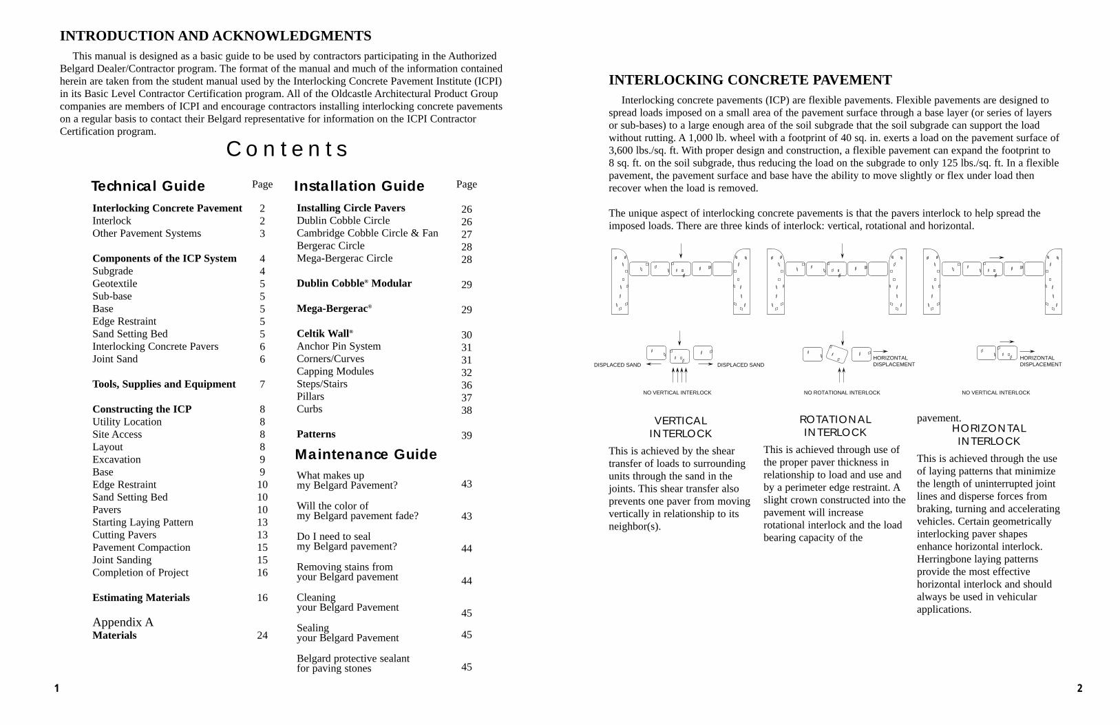
VERTICAL INTERLOCK
This is achieved by the sheartransfer of loads to surroundingunits through the sand in thejoints. This shear transfer also prevents one paver from movingvertically in relationship to itsneighbor(s).
ROTATIONALINTERLOCK
This is achieved through use of the proper paver thickness in relationship to load and use and by a perimeter edge restraint. Aslight crown constructed into thepavement will increaserotational interlock and the loadbearing capacity of the
pavement.HORIZONTALINTERLOCK
This is achieved through the useof laying patterns that minimizethe length of uninterrupted jointlines and disperse forces frombraking, turning and acceleratingvehicles. Certain geometricallyinterlocking paver shapesenhance horizontal interlock.Herringbone laying patterns provide the most effective horizontal interlock and shouldalways be used in vehicularapplications.
INTERLOCKING CONCRETE PAVEMENTInterlocking concrete pavements (ICP) are flexible pavements. Flexible pavements are designed to
spread loads imposed on a small area of the pavement surface through a base layer (or series of layersor sub-bases) to a large enough area of the soil subgrade that the soil subgrade can support the loadwithout rutting. A 1,000 lb. wheel with a footprint of 40 sq. in. exerts a load on the pavement surface of3,600 lbs./sq. ft. With proper design and construction, a flexible pavement can expand the footprint to 8 sq. ft. on the soil subgrade, thus reducing the load on the subgrade to only 125 lbs./sq. ft. In a flexiblepavement, the pavement surface and base have the ability to move slightly or flex under load thenrecover when the load is removed.
The unique aspect of interlocking concrete pavements is that the pavers interlock to help spread theimposed loads. There are three kinds of interlock: vertical, rotational and horizontal.
INTRODUCTION AND ACKNOWLEDGMENTSThis manual is designed as a basic guide to be used by contractors participating in the Authorized
Belgard Dealer/Contractor program. The format of the manual and much of the information containedherein are taken from the student manual used by the Interlocking Concrete Pavement Institute (ICPI)in its Basic Level Contractor Certification program. All of the Oldcastle Architectural Product Groupcompanies are members of ICPI and encourage contractors installing interlocking concrete pavementson a regular basis to contact their Belgard representative for information on the ICPI ContractorCertification program.
C o n t e n t sPage
Section 1 Interlocking Concrete Pavement 4Interlock 4Other Pavement Systems 5
Section 2 Components of the ICP System 6Subgrade 6Geotextile 7Sub-base 7Base 7Edge Restraint 7Sand Setting Bed 7Interlocking Concrete Pavers 8Joint Sand 8
COMPONENTS OF THE ICP SYSTEMThe eight components of the ICP system are:
SUBGRADE
The in-place soil on which the pavement will be constructed. The characteristics of the subgrade soilhave a major effect on the design and performance of the pavement and can also impact constructiontime and cost. The gradation, or distribution of the various size particles making up the subgrade soil,greatly influences the ability of the subgrade to support loads. Soils range from coarse grained sands tosilts and clays which contain the smallest particles. The smaller the particle size, the less strength thesubgrade will have. Clay soils are, in general, the weakest. The three most common methods used to rateor classify soils are discussed in Appendix A.
A simple way to quickly classify soils in the field is by visual appearance and feel. If coarse grainscan be seen and the soil feels gritty when rubbed between the fingers, then it is a sandy soil. If thegrains cannot be seen with the naked eye and it feels smooth, then it is a silt or clay. Don’t be fooled bythe apparent solidity of clay soils, they shift under loads.
A primary factor in the performance of soil under pavement is its ability to hold water. The higherthe water holding ability, the worse the soil generally performs as a foundation for pavement. Someeasy ways for the contractor to make a quick field identification are described below.
Patty Test - Evaluating the water holding capacity of a soil:• Mix the soil with enough water to make a putty-like consistency.• Form the sample into a patty, let it dry completely.• The greater the effort required to break the patty with fingers, the greater the plasticity, or ability to
hold water. In other words, the more water the soil can hold, the less suitable it is under pavement. • High dry-strength is a characteristic of clays. Silts and silty sands will break easily.
Shake Test - The dilatancy test, or a test for reaction to shaking:• Mix a tablespoon (15 ml.) of water with the soil sample in the hand. The sample should be soft but
not sticky.• Shake or jolt the sample in a closed palm of the hand a few times.• If water comes to the surface, the soil is fine sand.• If none or a little comes to the surface, it is silt or clay.• If squeezing the soil between the fingers causes the moisture to disappear, the soil is sandy.• If moisture does not readily disappear, then the soil is silty.• If moisture does not disappear at all, the soil is clay.
Snake Test - Evaluating the thread toughness for clay content:• A small sample of soil is moistened to the point where it is soft but not muddy or sticky.• It is rolled into a thread or “snake” between the hands.• The longer the thread, and the more it can be rolled without breaking, the higher the clay content.
The subgrade must be compacted to at least 95 percent of Standard Proctor Density before the base is installed.
In summary, the contractor achieves vertical, rotational and horizontal interlock by the interaction of these factors:
JOINT WIDTHS - consistent joint widths of approximately 1/8 in.
JOINT SAND - properly selected joint sand
THICKNESS OF PAVER - 60 mm. (2-3/8 in.) for pedestrian and residential driveways80 mm. (3-1/8 in.) for all other vehicular and industrial applications
EDGE RESTRAINT - non-moving fixed edge restraint
LAYING PATTERN - minimize length of uninterrupted joint lines in all directions. Most commonlyused pattern is Herringbone. Pavers which cannot be laid in Herringbone can usually be laid in anotheracceptable pattern.
PAVER SHAPE - shapes which allow Herringbone type laying patterns and which geometrically interlock on two or more sides with each other
CROWN - slight crown in pavement cross section
OTHER PAVEMENT SYSTEMSOther flexible pavement systems include asphalt (bituminous) pavements. These pavements are
designed and function in a similar manner to ICP. Stamped asphalt is in this category.Rigid pavements are designed to bridge or span soft areas in the soil subgrade. Rigid pavements
include poured-in-place Portland cement concrete, regular poured concrete, exposed aggregate concrete,stamped or imprinted concrete and decorative pavements mortared or adhered to a concrete surface or abituminous layer overlying concrete.
Comparison of Pavement SystemsInterlocking Concrete Pavements:• Flex without cracking.• Do not require expansion joints.• Resistant to spilled fuel and oil.• Resistant to freeze/thaw damage.• Resistant to de-icing compounds.• Virtually unlimited combination of solid and
blended colors, shapes and laying patterns.• May be used immediately upon completion
of installation.• May be disassembled to repair subgrade
or underground services then reinstalled with no unsightly patch.
• Skid and slip resistant surface.• Cooler surface.• Easy to work to grade transitions.• Long design life.• Low life cycle costs.• Virtually maintenance free.
Asphalt:• Flexible, but more apt to crack than ICP.• Cracks from evaporation of essential oils.• Dissolved by spilled fuels or oil.• Limited colors.• Patches and repairs obvious.• Relatively short design life.• Must be sealed on a regular basis.• Loses strength with increase in temperature.• Installation requires special equipment.
Poured-in-Place Concrete:• Cracks from load flexing and from thermal
expansion and contraction.• Difficult to effectively repair and repairs are obvious.• Less resistant to de-icing compounds than ICP.• Design life longer than asphalt, less than ICP.• Must cure before use.• Subject to environment during curing.• Needs expansion joints.• Stamped concrete typically colored only on the top.
43
INTERLOCKING CONCRETE PAVERS
A concrete paver unit meeting requirements of ASTM C936-96, a copy of which is included inAppendix A. The pavers “shall be capable of being lifted and placed with one hand, and shall have anexposed face (top surface) area less than or equal to 100.75 sq. in. The aspect ratio (that is, overalllength divided by thickness) shall be equal to or less than 4. A 12 in. x 12 in. paver does not qualifybecause it has a top surface area greater than 100.75 sq. in.
Other requirements of concrete pavers are:• Average compressive strength not less than 8,000 lbs. per sq. in.• Resistance to freezing and thawing. Less than 5 percent absorption• Dimensional tolerance
These requirements of ASTM C936 insure a uniform durable paver unit.Concrete pavers are manufactured in two thicknesses. Pavers 2-3/8 in. (60mm.) thick are used for
pedestrian applications such as walkways, patios, plazas and pool decks. They may also be used in residentialdriveways. Pavers 3-1/8 in. (80mm.) thick are used in vehicular traffic and heavy duty applications.
JOINT SAND
The sand used to fill the joint spaces between pavers to achieve vertical interlock. This sand must be clean, sharp, durable and well graded. Generally, it is best to use the same washed concrete sand(ASTM C33) used for the bedding layer as the joint sand. This is especially important in vehicular trafficked ICP. The sand should be spread, allowed to dry, then swept into the joints. The process can be accelerated if after the initial sweeping, a plate compactor is run over the pavement while the sweeping is continued. Finer sand conforming to ASTM C144 specifications may be used in pedestrian and residential driveway applications. Bagged “all-purpose” sand may be used in pedestrian ICP but masonry sand, box or play sand as well as stone dust or screenings should not be used. The recommended gradation for the joint sand may be found in Appendix A.
Be sure the joints are filled with sand. In some cases it may be necessary to re-sand the job in two to three weeks.
Summary:
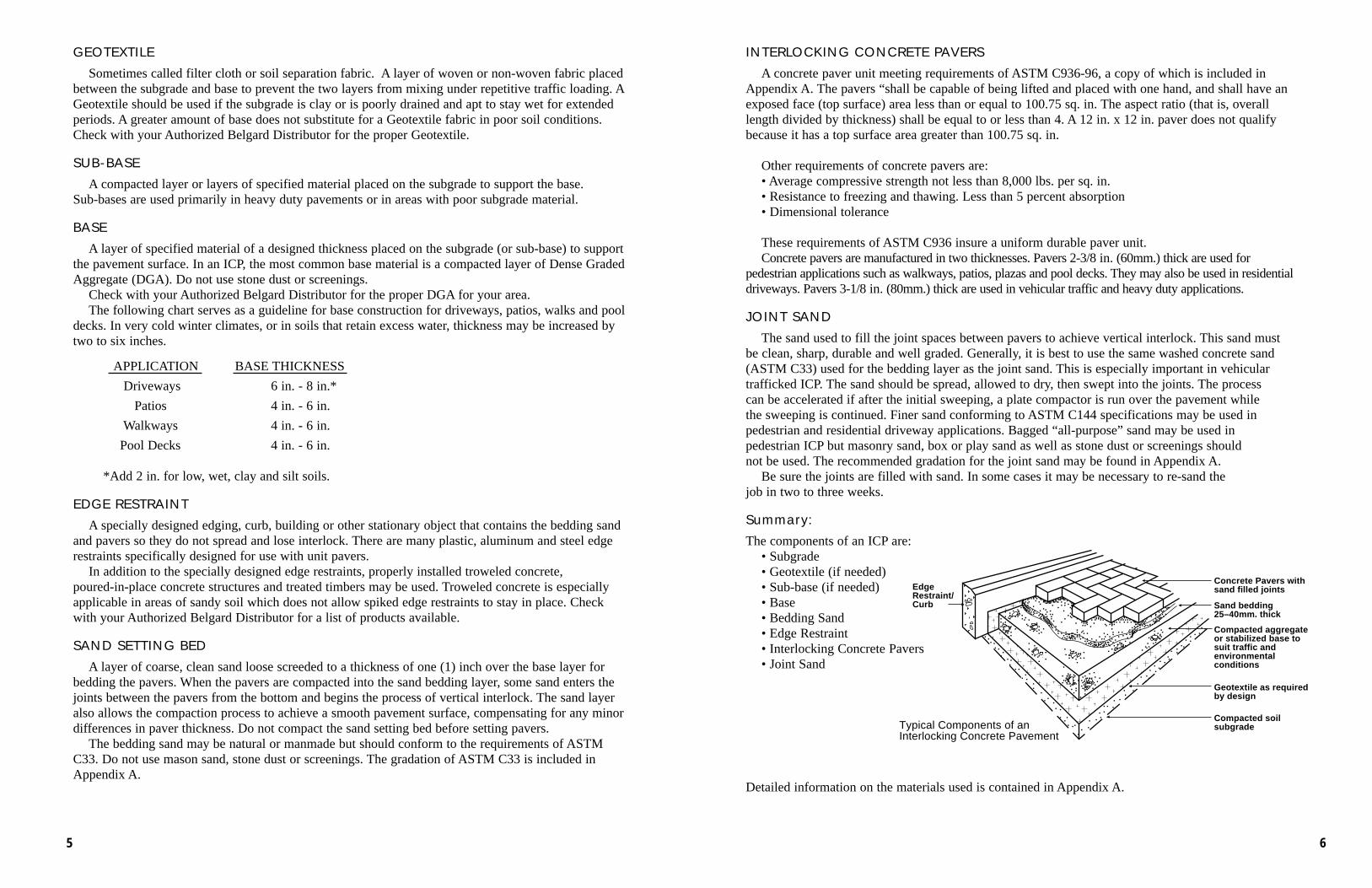
The components of an ICP are:• Subgrade• Geotextile (if needed)• Sub-base (if needed)• Base• Bedding Sand• Edge Restraint• Interlocking Concrete Pavers• Joint Sand
Detailed information on the materials used is contained in Appendix A.
EdgeRestraint/Curb
Concrete Pavers withsand filled joints
Sand bedding25–40mm. thick
Geotextile as required by design
Compacted aggregateor stabilized base to suit traffic andenvironmentalconditions
Compacted soilsubgradeTypical Components of an
Interlocking Concrete Pavement
GEOTEXTILE
Sometimes called filter cloth or soil separation fabric. A layer of woven or non-woven fabric placedbetween the subgrade and base to prevent the two layers from mixing under repetitive traffic loading. AGeotextile should be used if the subgrade is clay or is poorly drained and apt to stay wet for extendedperiods. A greater amount of base does not substitute for a Geotextile fabric in poor soil conditions.Check with your Authorized Belgard Distributor for the proper Geotextile.
SUB-BASE
A compacted layer or layers of specified material placed on the subgrade to support the base. Sub-bases are used primarily in heavy duty pavements or in areas with poor subgrade material.
BASE
A layer of specified material of a designed thickness placed on the subgrade (or sub-base) to supportthe pavement surface. In an ICP, the most common base material is a compacted layer of Dense GradedAggregate (DGA). Do not use stone dust or screenings.
Check with your Authorized Belgard Distributor for the proper DGA for your area. The following chart serves as a guideline for base construction for driveways, patios, walks and pool
decks. In very cold winter climates, or in soils that retain excess water, thickness may be increased bytwo to six inches.
APPLICATION BASE THICKNESS
Driveways 6 in. - 8 in.*
Patios 4 in. - 6 in.
Walkways 4 in. - 6 in.
Pool Decks 4 in. - 6 in.
*Add 2 in. for low, wet, clay and silt soils.
EDGE RESTRAINT
A specially designed edging, curb, building or other stationary object that contains the bedding sandand pavers so they do not spread and lose interlock. There are many plastic, aluminum and steel edgerestraints specifically designed for use with unit pavers.
In addition to the specially designed edge restraints, properly installed troweled concrete, poured-in-place concrete structures and treated timbers may be used. Troweled concrete is especiallyapplicable in areas of sandy soil which does not allow spiked edge restraints to stay in place. Checkwith your Authorized Belgard Distributor for a list of products available.
SAND SETTING BED
A layer of coarse, clean sand loose screeded to a thickness of one (1) inch over the base layer forbedding the pavers. When the pavers are compacted into the sand bedding layer, some sand enters thejoints between the pavers from the bottom and begins the process of vertical interlock. The sand layeralso allows the compaction process to achieve a smooth pavement surface, compensating for any minordifferences in paver thickness. Do not compact the sand setting bed before setting pavers.
The bedding sand may be natural or manmade but should conform to the requirements of ASTMC33. Do not use mason sand, stone dust or screenings. The gradation of ASTM C33 is included inAppendix A.
65
Equipment:Installation equipment may be owned or rented. The most common equipment needed is:• Builders level or transit level with tripod and rod. Laser levels are excellent.• Vibratory plate compactor rated minimum 5000 ft. lbs.• Masonry saw• Table saw, wet or dry, or a hand held cut-off saw. Either should be gasoline powered.
A hand held cut-off saw is the most flexible and productive.
Heavy Equipment:• Skid-Steer Loader capable of lifting 5000 lbs. - equipped with interchangeable bucket, forks and
rotary broom• Vibratory Roller - used for subgrade and base compaction on larger jobs• Jumping Jack Compactor - for compacting trenches• Backhoe - for excavation (especially demolition)• Dump Truck - to haul excavated materials and to deliver material to job site
TOOLS, SUPPLIES AND EQUIPMENTMost of the tools, supplies and equipment needed to install ICP are common to contractors involved
in residential site work. The heavier and more expensive equipment may be easily rented if the work volume justifies the purchase. Some tools have been designed especially to facilitate the installation ofICP and are available through your Authorized Belgard Distributor.
QTY QTY1 Folding 6 ft. ruler 1 4 ft. Level2 16 ft. Tapes 1 Torpedo Level1 100 ft. Tape 1 Line Level1 Steel or Aluminum Carpenter Square 1 Mason Trowel - Rectangular1 Claw Hammer 1 Mason Trowel - Pointed1 Mason Hammer 1 Mason Wood Float1 3 lb. Maul 1 4 in. Brickset (Mason Chisel)1 12 lb. Sledge Hammer 1 Pair Metal Snips1 Rubber or Deadblow Hammer 1 Shovel(s) Square Point1 Steel Garden Rake 1 Shovel(s) Round Point1 Push Broom 1 Slim Jim Pry Bar1 Contractor’s Wheel Barrow 1 36 in. Crow Bar1 Screed Board (Magnesium) or 2 Large Flat Blade Screw Drivers
10 ft.-12 ft. wood 2x4’s 6 Screed Rails 3/4 in. ID Steel Pipe or1 Hacksaw 1 in. Square Steel tubing approximately1 Carpenter’s Saw 10 ft. long (a couple of 4 ft. pieces are handy)1 Plumb Bob 1 Garden Hose (75 ft.-100 ft.)1 Chalk Line 1 Hand Tamper
Some special tools designed specifically for the ICP industry are:• Paver Cart - to transport full straps of pavers • Paver Extractor - to remove installed pavers• Dead Blow Rubber Hammer - to help adjust pavers• Paver Scribe - to mark pavers for cutting• Paver Adjuster - to move installed pavers to straighten lines
Personal Safety and Comfort Supplies:• Eye Protection • Ear Protection (muffs or plugs)• Dust Mask (disposable) • Steel Toed Shoes• Gloves • Knee Pads• Back Support • Finger Tape (can use duct tape)• First Aid Kit • Water Cooler
Before beginning any phase of the construction process, make sure that all underground utilities, services and structures have been located and clearly marked on the ground surface in all areas involved in theconstruction process including access lanes. In many areas, a single number such as Miss Utilities may be called.
Items to be located are:• Electrical • Sanitary sewer • Gas • Septic tank • Water supply • Telephone • Storm sewer • Cable TV • Drainfield • Irrigation piping
SITE ACCESS
Before any demolition, delivery or construction equipment is allowed on site, make sure that there are nohazardous conditions such as overhead electric lines in the way. Plan all activities so that no damage will occurto existing pavements, structures, trees, shrubbery, gardens or other site amenities.
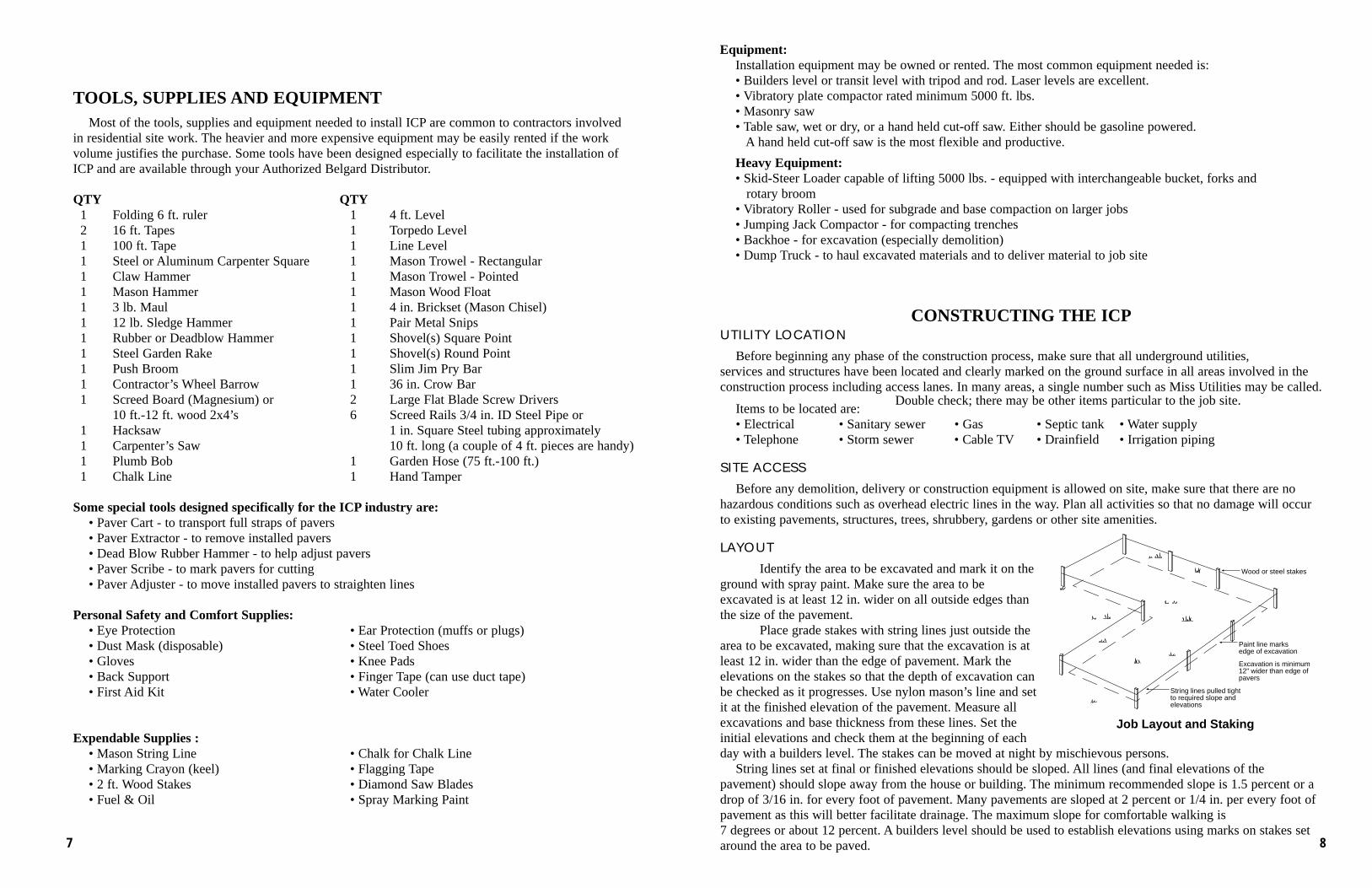
LAYOUT
Identify the area to be excavated and mark it on theground with spray paint. Make sure the area to beexcavated is at least 12 in. wider on all outside edges thanthe size of the pavement.
Place grade stakes with string lines just outside thearea to be excavated, making sure that the excavation is atleast 12 in. wider than the edge of pavement. Mark theelevations on the stakes so that the depth of excavation canbe checked as it progresses. Use nylon mason’s line and setit at the finished elevation of the pavement. Measure allexcavations and base thickness from these lines. Set theinitial elevations and check them at the beginning of eachday with a builders level. The stakes can be moved at night by mischievous persons.
String lines set at final or finished elevations should be sloped. All lines (and final elevations of thepavement) should slope away from the house or building. The minimum recommended slope is 1.5 percent or adrop of 3/16 in. for every foot of pavement. Many pavements are sloped at 2 percent or 1/4 in. per every foot of pavement as this will better facilitate drainage. The maximum slope for comfortable walking is 7 degrees or about 12 percent. A builders level should be used to establish elevations using marks on stakes setaround the area to be paved.
Wood or steel stakes
Paint line marks edge of excavation
Excavation is minimum 12" wider than edge of pavers
String lines pulled tight to required slope and elevations
Job Layout and Staking
Double check; there may be other items particular to the job site.
87
EDGE RESTRAINT
Edge restraints must be installed on that part of the pavement edge which is not restrained byan existing structure such as a building, concrete curb or concrete slab.
Edge restraints are typically placed before installing the bedding sand and pavers. Some edgerestraints can be installed after placement of the pavers and before compaction. Troweled concrete edge restraint is installed after the pavers have been placed.
A detailed description of the various types of edge restraints is contained in Appendix A. Consultyour Authorized Belgard Distributor for the edge restraint(s) recommended for your area. Also refer to ICPI Tech Spec 3 “Edge Restraints for Interlocking Concrete Pavements”.
Be sure that any area where bedding or joint sand can escape through or under the edge restraintis lined with a strip of Geotextile. Loss of sand will cause eventual settlement of the pavers.
Back fill outside of edge restraint as soon as possible to prevent sand from escaping under the edge restraint.
SAND SETTING BED
Loose screed the washed concrete sand (see Appendix A) to an uniform thickness of 1 in. over thecompacted base course. In no case should the sand be greater than 1-1/2 in. thick.
If the edge restraint has already been installed, the screed board may be notched to ride on the edge restraint on one or both ends. The notch should be cut to allow for the screeding of a 1 in. thick sand layer.
If the edge restraint cannot be used to carry the screed board, screed rails must be used. Screed railsmay be wood, plastic or iron pipe or square steel tubing. The rails should be sized to allow for a 1 in.thick sand bed. For example, a 3/4 in. iron pipe (3/4 in. is the inside pipe diameter) has an outside diameter of approximately 1 in.
Place the screed rails parallel to each other and close enough together to enable the screed board tobe pulled along the rails without falling off. Set the top of the rails to the desired elevation below gradelines and stabilize by hand packing sand along both sides of the rail.
Place the washed concrete sand between the screed rails and rough screed with a shovel, steel rakeor lute. Excess sand makes the screed board difficult to pull. Place screed board on the rails and drawforward leaving a smooth surface. Fill in and rescreed any open streaks.
When a screed rail is no longer needed, it should be carefully removed and the void filled with sandand hand floated.
Do not compact the sand setting bed before laying pavers.
EXCAVATION/SUBGRADE
Make sure that the area to be excavated is at least 12 in. wider than the limits of the ICP. This provides a firm base to support the edge of the pavement and the edge restraint.
Make sure that the depth to be excavated is measured from finished pavement surface elevations and is marked on all grade stakes. The bottom of excavations, below finished pavement elevation,should equal the total thickness of the designed base, sand bed (after paver installation and compaction) and the paver being used.
Try not to disturb the subgrade below the planned excavation depth. Over excavation is costly and can cause future problems.
When all excavation is completed, compact the subgrade with a vibratory plate compactor. Makesure that compaction is thorough, uniform and complete. If soft spots are encountered, they should be removed and backfilled with the material to be used for the base. If the subgrade is too wet to compact, allow it to dry or try adding a few inches of dry base material before compacting.
BASE
The recommended DGA base material (see Appendix A) should be spread in layers of uniformthickness then compacted. The thickness of the layer depends on the method of compaction and theplanned use of the pavement. While compaction of the subgrade and base layers is key to theperformance of any pavement, it is absolutely essential to pavements trafficked by vehicles. The 4 in. -6 in. base for patios, walkways and pool decks may be placed in two or three layers and compactedwith a vibratory plate compactor of 5,000 ft. lbs. of force or greater. The 6 in. - 8 in. base fordriveways may be placed in two lifts of 3 in. - 4 in. if a vibratory roller is used.
Place and compact the base material as recommended, making sure to keep the material lightlydampened. If free water appears on the base surface during compaction, the material is too wet andshould be allowed to dry (or add a layer of dryer base material) before continuing compaction.
Be sure to thoroughly compact along edges, in corners and around structures. These are the most difficult areas to treat and the most apt to cause future settlement problems.
Do not use frozen base material and do not place base material over a frozen subgrade.Be sure that the outside limits are at least 12 in. wider than the outside limits of the pavement.When proper compaction of DGA has been achieved, the surface should be smooth, leave no
areas into which the bedding sand can migrate. It may be necessary to fill any such areas with a finer material then recompact. The finished base surface should be flat (no more than 3/8 in. plus or minus variation under a 10 ft. straight edge) and uniformly true to grade.
Summary:• Base must be 12 in. wider than pavement on all sides.• Use proper base material.• Do not place frozen base material.• Do not place base material over frozen subgrade.• Place and compact base in layers.• Fully compact.
PAVERS
In most ICP projects, the pavers, regardless of paver shape, are laid in patterns where two sets ofjoints run perpendicular to each other. Radii or curves are cut into the pavement after the field pavershave been laid but not compacted. Straight joint lines not only make the finished pavement look cleanand sharp but make installation much easier. If pavers shaped to geometrically interlock with each otherare not laid in straight lines, they will not fit together.
To keep joint lines straight, parallel string lines or chalk lines snapped on the sand setting bed shouldbe used. The lines should be spaced five to ten feet apart with the spacing equal to the laying modulusof the paver shape being installed. This can be determined by laying a course of pavers in the properpattern with 1/8 in. joints and measuring the distance between at the desired line separation distance.
Procedure:• Snap a string line on the screeded sand in the center of the area(s) to be placed.• The line should be perpendicular to the laying face.• Place pavers in the given laying pattern on both sides of the line.• If additional lines are snapped, they should be parallel to each other. Check this by measuring the
distances at the opposite ends of each line. They should be equal.• If they are not parallel, they can be erased and snapped again. 109
3:4:5 Triangle may be used to establish a 90 degree angle or to check existing corners:
6' (3m)
8' (4m)
10' (5m)
90°
6' (3m)
8' (4m)
10' (5m)
A quick way to establish a line perpendicular to an edge (no corner walls) is with the following procedure:• Measure and mark the length of the edge, or line, from which paving will begin. The line can be 10-20
ft. (3-7m.) long. This line is where an edge restraint will be placed, or where one is already placed.• Mark exactly the half way point on the line that was just measured. In other words, divide the line in half.• Take one tape measure and extend it from the other end of the line at an angle toward the center.
Be sure the tape extends past the middle of the line by a foot or two (0.2m.-0.6m.).• Take a second tape measure and extend it from the other end of the line at an angle toward the center.• Overlap one tape on the other and match the
length of both tapes. The same marked dimensions on each tape should be touching each other.
• Snap a line from the point where thetwo tape measures cross to the centerof the line.
• This line is perpendicular to the linefrom which paving will begin.
90°
Edge RestraintExact Midpoint
TapeMeasures
String Line
Equi-distantfrom midpoint
Parallel string lines are also used topave around openings in the pavementsuch as manholes or swimming pools.
Procedure:• Pull perpendicular string or
snap chalk lines on all four sides of the opening.
• Lay pavers on one side, then the other.
• Count the courses needed to surround the openings on each side. They should be equal in number on both sides.
• Then fill around the remain-ing side of the opening.
• Cut pavers to fit and fill against theedge restraint around the opening.
Plan your installation to begin along a straight line and preferably in a corner which is easily accessible.Make absolutely certain that the beginning corner is a true 90 degree angle. If the intersection of 2 sides isnot a true 90 degree angle, you must establish a 90 degree starting point.
90°
Set string lines square on sides of openings
②
④
③
①
Lay one sidefirst
Fill thisarea
Lay other sidenext
Coursesmatchotherside
OPENINGIN
PAVEMENT
90°
Existing wall
String line
String line—90°
Check 90° angle of existing walls or edges
Fill gapswith cut pavers
Lay pavers toperpendicular string lines
direction ofpaving
Parallel chalk lines snapped in bedding sand or string lines pulled above sand and pavers
12' (4m)
6' (2m)6' (2m)
1211
Edge Pavers and Paver Cutting
Especially manufactured edge units are available for some paver shapes. Check with your AuthorizedBelgard Dealer for availability of these units.
In most cases, pavers along the pavement edges will need to be cut. The four types of cutting equipment generally available are:
1. Mechanical cutter or guillotine splitter. This equipment cuts pavers between two steel bladesthrough hydraulic or mechanical pressure. The cutting process is quick but the cut edge tends to berough. The equipment is relatively inexpensive.
2. Gasoline or electric powered saws mounted on a stand. These saws are generally set up to be runwet but can be run with a dry diamond blade. Very accurate cuts can be made but in most cases thepavers must be marked, brought to the saw, cut, then returned to the edge and installed. The process islabor intensive. Gasoline powered saws may be mounted on a coxet to facilitate the process.
3. Walk behind diamond saw. Powered in most cases by a gasoline engine, the units roll on wheelswhile cutting. They are usually set up to run wet but can use a dry diamond blade. The advantage is thatthe pavers may be cut in place. The quality of cut is excellent but the saws are awkward to maneuver.
4. Gasoline powered cut-off or quick saws. These hand held saws are similar to chain saws with thediamond saw blade replacing the chain. While some cut-off saws can be run wet, most are used with dry blades. These units provide good output and, in the hands of an experienced operator, excellent quality of cut. Cut-off saws have become the most used equipment for cutting pavers.
TipsDiamond saw blades come in wet or dry versions. Dry blades may be run wet but wet blades should
never be run dry. Use of water with either type blade extends blade life.Care must be taken to make sure that the slurry (mixture of water and cutting dust) from wet saws
or dust from dry saws is washed off installed pavers immediately before it dries. Surrounding structures, vegetation and automobiles should be protected from the dust. Cut-off saws with dust collection capabilityhave recently become available. Check with your Authorized Belgard Dealer for the proper cutting equipment.
Cutting ProcedureMark lines to be cut with lumber pencil or crayon, chalk, welders soapstone or water-base liquid marker.
Do not use a marker which will not eventually come off. It is best to use a color which is easily visibleagainst the color of the paver. Curved lines may be marked by using a garden hose as a guide.
The pavement will perform best if the size of cut units left in the pavement is as large as possible. Thinpieces tend to break or displace with time and use. In most cases, the pattern may be adjusted at or near theedge to allow for larger cut pieces. A border or header course of whole pavers between the field pavers andthe edge restraint tends to keep the cut field pavers in place better than the edge restraint alone. The borderpavers also add a neat finished appearance to the pavement.
Cut and place all edger pieces before compacting the pavers and applying joint sand.
Summary:• Use proper hand, eye, ear and respiratory protection equipment.• Mark lines to be cut.• Maximize size of cut pieces to remain in pavement.• Make clean neat cuts.• Make all cuts before compacting pavement.• Clean all cut residue from pavement immediately.• Use paver border or header course as often as possible.
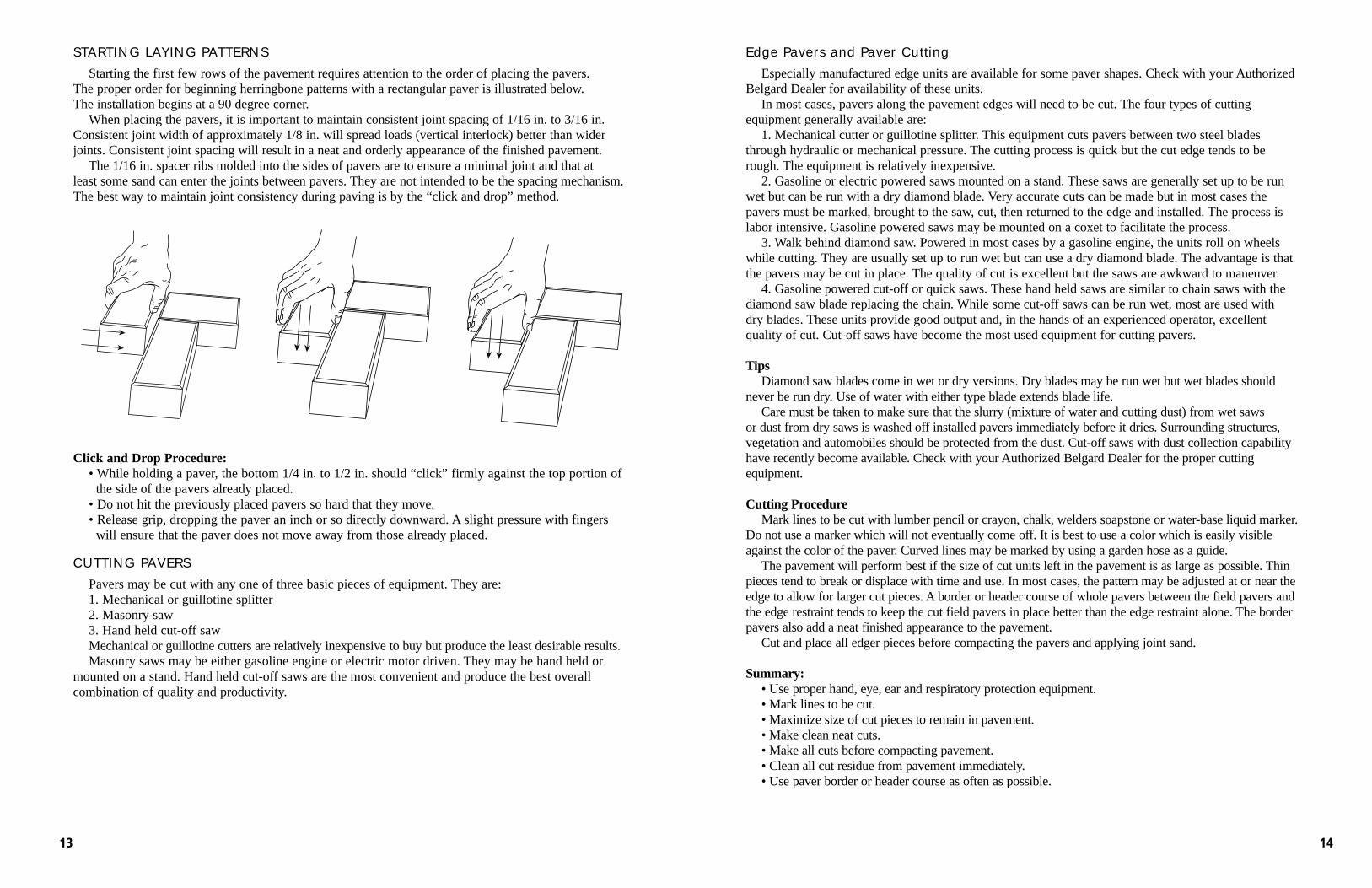
STARTING LAYING PATTERNS
Starting the first few rows of the pavement requires attention to the order of placing the pavers. The proper order for beginning herringbone patterns with a rectangular paver is illustrated below. The installation begins at a 90 degree corner.
When placing the pavers, it is important to maintain consistent joint spacing of 1/16 in. to 3/16 in.Consistent joint width of approximately 1/8 in. will spread loads (vertical interlock) better than widerjoints. Consistent joint spacing will result in a neat and orderly appearance of the finished pavement.
The 1/16 in. spacer ribs molded into the sides of pavers are to ensure a minimal joint and that at least some sand can enter the joints between pavers. They are not intended to be the spacing mechanism.The best way to maintain joint consistency during paving is by the “click and drop” method.
Click and Drop Procedure:• While holding a paver, the bottom 1/4 in. to 1/2 in. should “click” firmly against the top portion of
the side of the pavers already placed.• Do not hit the previously placed pavers so hard that they move.• Release grip, dropping the paver an inch or so directly downward. A slight pressure with fingers
will ensure that the paver does not move away from those already placed.
CUTTING PAVERS
Pavers may be cut with any one of three basic pieces of equipment. They are:1. Mechanical or guillotine splitter2. Masonry saw3. Hand held cut-off sawMechanical or guillotine cutters are relatively inexpensive to buy but produce the least desirable results.Masonry saws may be either gasoline engine or electric motor driven. They may be hand held or
mounted on a stand. Hand held cut-off saws are the most convenient and produce the best overall combination of quality and productivity.
1413
COMPLETION OF PROJECT
When the installation has been completed, clean up the site. Some pavers of each shape and color usedmay be left with owner for possible future replacement. Store these pavers neatly where the ownerdirects. Walk the job with the owner and address any problems immediately. Review maintenance procedures with the owner and leave information regarding care and maintenance with him/her.
PAVEMENT COMPACTION AND JOINT SANDING
Compaction of the ICP evens the tops of the pavers and begins the process of vertical interlock byforcing some of the bedding into the joints from the bottom.
On small jobs, compaction should take place after all pavers, including cut edges, are in place. Onjobs lasting more than one day, all pavers placed should be compacted and the joints filled at the end ofthe workday. Do not compact or fill joints within 3 ft. of any unrestrained or incomplete edge. Do notspread joint sand before initial compaction of pavement.
Using a gasoline powered vibratory plate compactor with a minimum compaction force of 5000 ft.lbs. for 3-1/8 in. pavers, follow this procedure:
Compacting Procedure• Start on one edge of the pavement and
compact the perimeter.• Compact in overlapping rows on the
rest of pavement.• Compact the pavement again but in
the opposite direction. All pavers will need to be exposed to at least two passes of the compactor.
• Do not compact within 3 ft. of an unre-strained edge or the pavers will creep out.
• The operator looks for broken pavers just behind the plate compactor and marks them while compacting. The broken pavers are removed with a paver extractor and replaced with whole units.
Figure 3 (right)Compaction sequence working from the
perimeter to the center of the pavement. Allpavers should have two passes of the plate vibrator over them prior to filling the joints. After the jointsare filled with sand, follow the same compaction sequence from the perimeter to the center.
JOINT SANDING
After compaction of pavement and replacement and recompaction of replacement pavers, spread thejoint sand. Refer to Section 2, Joint Sand for recommended sands. Dry sand works best, so if the sandis damp, allow it to dry. Sweep the dry sand into the joints. If necessary, dry bagged sand conforming toASTM C144 may be used (see Appendix A). Do not use mason sand, play sand or sandbox sand. Afterthe initial sweeping, the filling of the joints can be expedited by alternating sweeping and passes of thevibratory plate compactor. Continue until all joints are filled. It is a good idea to reinspect a job two tothree weeks after completion at which time it may be necessary to re-sweep sand into the joints.
Summary:• Compact pavement after pavers are installed and before joint sand is spread.• Replace broken pavers while compacting and before applying joint sand.• Spread and dry joint sand.• Sweep joint sand into joints and fill by alternating sweeping and vibrating.• Check job in 2-3 weeks and re-sand if necessary.• Sweep off excess sand. On some commercial jobs, excess sand may be left on the pavement to
help ensure joints are filled.
ESTIMATING MATERIALS
EXCAVATION
Calculate the area to be excavated. Remember to include the 12 in. outside the area to be paved. If an electronic digitizer is not available, break the area down into geometric shapes (squares, rectangles,triangles or circles), calculate the area of each, then add all together to arrive at total area in square feet.
Calculate volume of soil to be excavated by multiplying the total area in square feet by the depth tobe excavated in feet. This will give the total cubic feet of soil to be excavated. In most residentialprojects, the depth to be excavated is uniform or easily averaged over the area to be paved. If the
pavement is to be cut into a hill slope or will be built partially over an area to be filled, be sure to consider these conditions in your estimate. In the first case, more material will need to be excavatedand disposed of. Some or all of that material may possibly be used as fill.
When soil is excavated it expands in volume. This expansion is called “swell” and ranges from 30 percent for clay to 15 percent for sand with “average” soil expanding about 25 percent. If the average soil expands 25 percent then the volume after excavation, or loose volume, is 125 percentgreater than the volume of the soil in place. Thus, if the calculated in place volume of the soil to beexcavated is 100 cubic yards, the volume to be hauled is approximately 125 cu. yds. (100 x 1.25).
Since the volume of soil increases when excavated, the weight per unit of volume must decrease. The average soil weighs approximately 3250 lbs. (1.625 tons) per cubic yard in place and approximately2600 lbs. (1.3 tons) per cu. yds. after excavation. Thus, the 125 cu. yds. to be hauled in the last examplewould weigh 162.5 tons (125 x 1.3).
Knowing the volume and weight of soil to be excavated, hauled and disposed of is absolutely necessaryto accurately estimate time and cost. More detailed information is contained in Appendix A-Materials.
BASE
Calculate the base material by multiplying the area excavated in square feet by the design depth ofthe base in feet after compaction. Divide the result by 27 to obtain the cubic yards of base materialneeded in the compacted state.
Since the base material will usually be purchased by the ton, the volume needed after compactionmust be converted from cubic yards to tons. This conversion can be made accurately if the bulk densityof the base material is known. If the bulk density is not known, multiply the calculated volume neededby 1.6 to get tons needed.
EDGE RESTRAINT
The lineal feet of edge restraint required is simply the total feet of pavement edge which must berestrained by the specified edge restraint system. In many cases, both straight and curved restraints must be installed. Total quantities of each should be estimated.
If the edge restraint to be used requires stakes or spikes, this quantity must also be estimated. Space stakes or spikes as recommended by the manufacturer of the edge restraint system used. This information may be obtained from your Authorized Belgard Dealer.
BEDDING SAND
The quantity of bedding sand will vary with the thickness of the loose screeded sand bed, 1 in. to 1-1/2 in., and with the moisture content of the sand being delivered. A good rule of thumb, however, isto order 1/2 ton of ASTM C33, washed concrete sand for every 100 sq. ft. of installed pavement. Thisshould suffice for both the bedding and joint filling.
1615
EDGE RESTRAINTS
Restraints hold the pavers tightly together, enabling consistent interlock of the units across the entire pavement.They prevent pavers from spreading due to horizontal forces from tires and minor settlement. Edge restraints aredesigned to remain stationary while receiving occasional impacts from tires.
When a compacted aggregate base supports the paver and bedding sand, the base should extend beyond therestraint. The rule of thumb is that the base should extend beyond the restraint the same dimension as the thickness ofthe base material. For example, if the base is 6 in. thick, then it should extend at least 6 in. beyond the outside edgeof the restraints. This contributes stability to the restraint and pavement edge especially in soils subject to heaving.Soil backfield is never a suitable edge restraint and should never be installed on top of the bedding sand.
If there is a possibility of sand loss from beneath the pavers, or between the joints of the edge restraint, Geotextile(filter cloth) is recommended to prevent its migration. A 12 in. (0.3m.) wide strip can be applied along the base andturned up along the sides of the restraints. Filter cloth generally is not required across the entire surface of the base,nor should it be placed on top of the bedding sand.
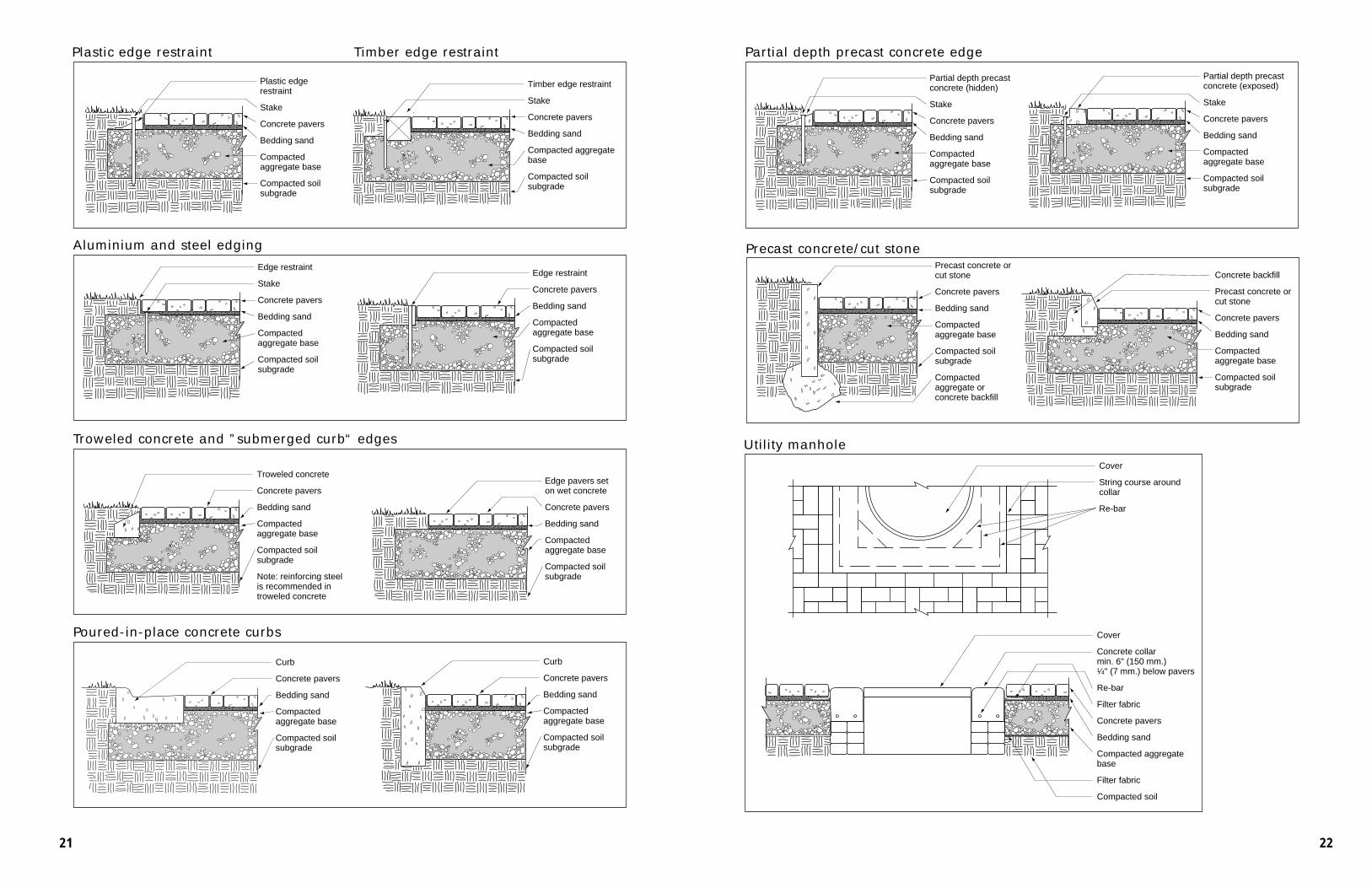
There are two general types of edge restraints. Those made elsewhere and installed at the site include precastconcrete, plastic, cut stone, aluminum, steel and timber. Restraints formed on-site are made of poured-in-placeconcrete.
Full depth precast concrete or cut stone edging generally extends the depth of the base material. They can be compacted soil (not subject to heaving), compacted aggregate or concrete backfield. The preferred method of installation with vehicular pavements is for the curb to rest on the compacted aggregate road base.
Partial depth precast concrete edge restraints may be used for residential and light duty commercial applications.These precast units are anchored on a compacted aggregate base with steel spikes. The spikes are typically 3/8 in.diameter. Depending on the design, the top on the concrete edge can be hidden or exposed.
Aluminum and steel edging should be selected to provide a smooth vertical surface against the pavers. L-shapededging provides additional stability. Stakes fastened to the edging should be below the pavers or on the outside of therestraints. Steel should be painted or galvanized so that rust does not stain the pavers. Spikes to secure steel and aluminum edging should extend well into the base course. Consult manufacturer’s literature for recommended spacing of the spikes. Aluminum and steel edgings are manufactured in different thickness. The thickest edging is recommended when pavers are subjected to vehicular traffic.
Timber should only be used to restrain residential patios and walks. It should be treated to resist insects and rot. A nominal 6 in. x 6 in. minimum dimension will restrain the bedding sand and 2 3/8 in. thick pavers. Smallerdimensioned lumber will likely warp. Stakes should be placed on the outside of the lumber, or below the pavers ifplaced on the inside. The stakes should extend into the base.
Plastic edging installs quickly and will not rust or rot. Plastic edging should be specifically designed for usewith pavers. It can be used with light duty residential, commercial or on some heavy duty, industrial applications,depending on the design. It should be firmly anchored into the compacted aggregate base course with steel spikes.Consult the manufacturer’s literature for the recommended spacing of the spikes. Edging for planting beds and lower gardens is not an acceptable restraint for interlocking concrete pavements.
Elevations should be set accurately for restraints that rest on the base. For example, 2 3/8 in. thick pavers with 1 1/4 in. of bedding sand would have a base elevation set 3 in. below that of the finish elevation of the pavers. Thisallows 1/4 in. settlement from compaction and 1/8 in. for minor settling over time.
Restraints formed on-site, poured-in-place concrete curbs, or combination curb and gutters required by municipalities make suitable restraints for pavers. Exposed concrete edges should have a 1/8 in. radius edge to reduce the likelihood of chipping. As with precast, the side of the curbs should extend well below the sand bedding course.
Troweled concrete from a bag mix, or batched on-site, can be applied without forms against edge pavers and onthe compacted base. If the top of the concrete edge is recessed and slopes away from the pavers, grass can grow nextto them. The depth below the surface of the pavers must be sufficient to prevent the concrete from becoming a heatsink that dries the grass and topsoil. This edge restraint is suitable for pavers subjected to pedestrian traffic and forresidential driveways. Troweled edges should be at least 6 in. wide. Steel reinforcing such as DuraWall should beplaced in the concrete to increase service life.
Troweled concrete curbs are not recommended in freezing climates as they may crack and be an on-going maintenance problem.
PAVERS
In simple straightforward projects requiring no cutting loss, the quantity of pavers to be ordered isequal to the area of the pavement, plus a 2 percent cull factor rounded up to the next highest packageunit. In some cases it may be possible to order pavers in straps or section quantities while in others itmay be necessary to order full cubes.
An additional quantity must be added for portions of pavers lost on edges which must be cut. A good rule of thumb is to add 30 sq. ft. of pavers for each 100 linear ft. of cut edge.
Edge pavers must be calculated separately for each paver shape. This information is available in theProduct Guide available from your Authorized Belgard Dealer. Remember, edge pavers are only availablefor a limited number of paver shapes and may only be used on straight edges parallel to the laying pattern.
Border pavers, such as a header course, must be calculated based on the paver shape being used andthe border pattern to be installed. In the common soldier course border using a 4 in. x 8 in. rectangularpaver, 3 pavers are needed per 1 ft. of border or 0.67 sq. ft. of 4 in. x 8 in. pavers. The ordered quantitywould be 0.67 x the lineal feet of border plus 2 percent rounded up to the next package unit.
If bands are to be inset into the paver field, it is usually best to lay the entire field then saw cut andremove field pavers to install the band pavers. In this case, do not deduct the quantity of band paversfrom the gross field pavers required.
JOINT SAND
If the same sand used to fill the joints is used for the sand setting bed, the quantity will be includedin the bedding sand estimate.
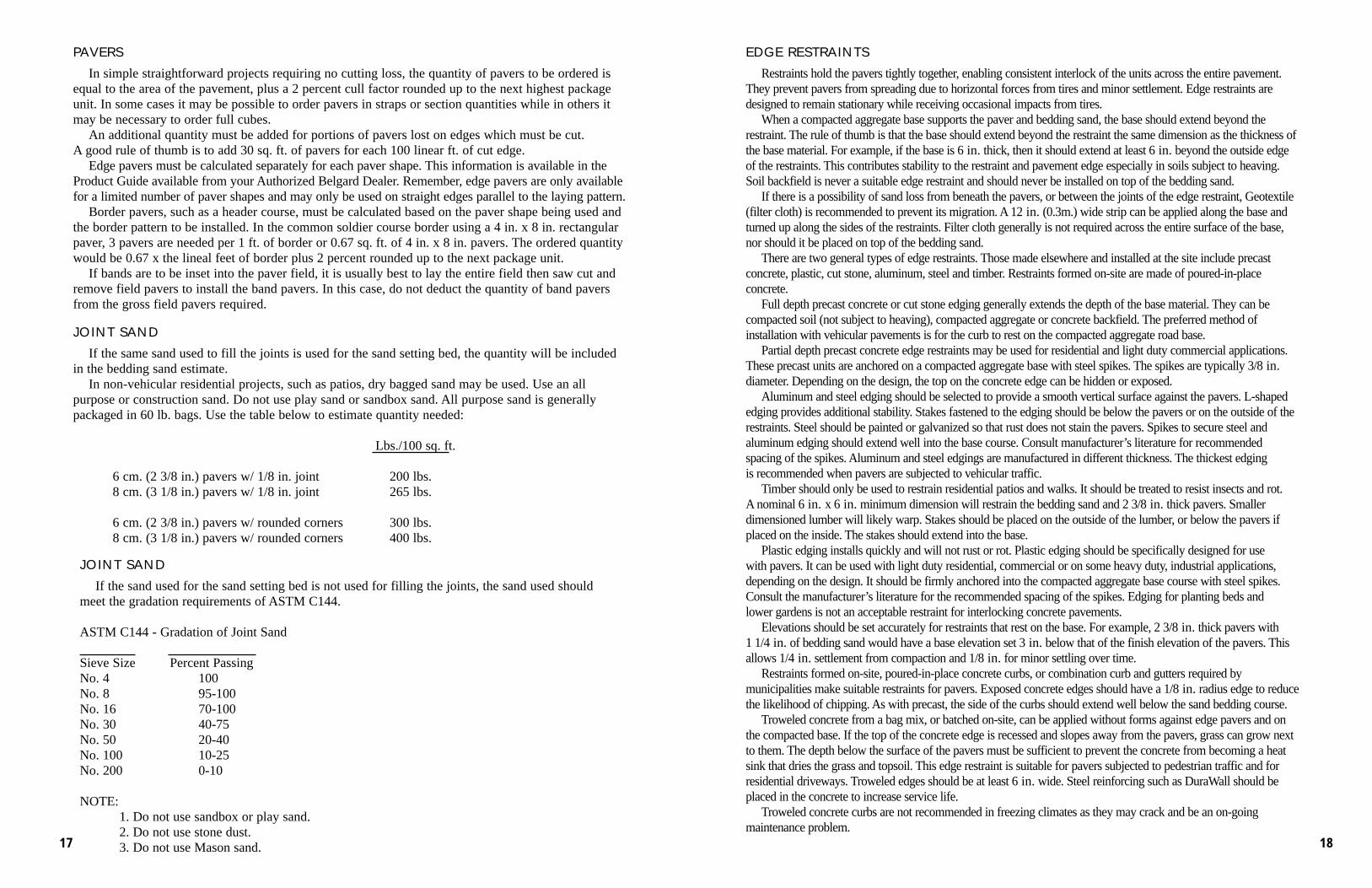
In non-vehicular residential projects, such as patios, dry bagged sand may be used. Use an all purpose or construction sand. Do not use play sand or sandbox sand. All purpose sand is generallypackaged in 60 lb. bags. Use the table below to estimate quantity needed:
Lbs./100 sq. ft.
6 cm. (2 3/8 in.) pavers w/ 1/8 in. joint 200 lbs.8 cm. (3 1/8 in.) pavers w/ 1/8 in. joint 265 lbs.
NOTE:1. Do not use sandbox or play sand.2. Do not use stone dust.3. Do not use Mason sand. 1817
(1) Use 6 in. compacted base in driveways.(2) Use Geotextile between subgrade and base and thickness base to 8 in. in driveways.(3) Use Geotextile between subgrade and base and thickness base to 8 in. in driveways and thicken
driveway base to 10 in.
BASE MATERIAL
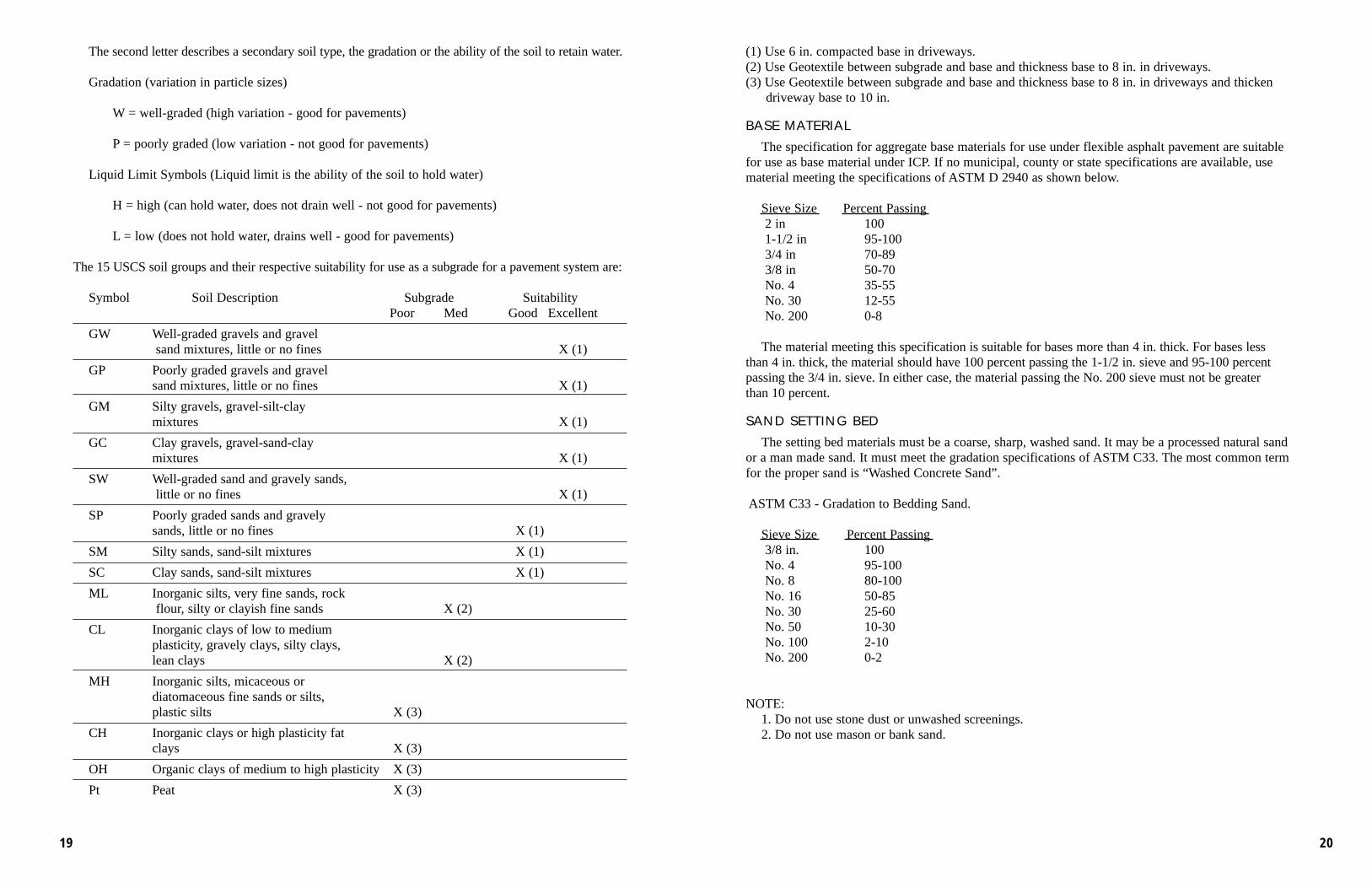
The specification for aggregate base materials for use under flexible asphalt pavement are suitablefor use as base material under ICP. If no municipal, county or state specifications are available, use material meeting the specifications of ASTM D 2940 as shown below.
Sieve Size Percent Passing2 in 1001-1/2 in 95-1003/4 in 70-893/8 in 50-70No. 4 35-55No. 30 12-55No. 200 0-8
The material meeting this specification is suitable for bases more than 4 in. thick. For bases less than 4 in. thick, the material should have 100 percent passing the 1-1/2 in. sieve and 95-100 percent passing the 3/4 in. sieve. In either case, the material passing the No. 200 sieve must not be greater than 10 percent.
SAND SETTING BED
The setting bed materials must be a coarse, sharp, washed sand. It may be a processed natural sand or a man made sand. It must meet the gradation specifications of ASTM C33. The most common termfor the proper sand is “Washed Concrete Sand”.
Note: reinforcing steel is recommended in troweled concrete
Edge pavers set on wet concrete
Concrete pavers
Bedding sand
Compacted aggregate base
Compacted soil subgrade
Troweled concrete and ”submerged curb“ edges
Curb
Concrete pavers
Bedding sand
Compacted aggregate base
Compacted soil subgrade
Curb
Concrete pavers
Bedding sand
Compacted aggregate base
Compacted soil subgrade
Poured-in-place concrete curbs
2221
A p p e n d i x A
MATERIALS
GENERAL
Gradation of subgrade soil, base material and beddingand joint sands is an important property of these materials.The size and distribution of their particle sizes greatly influence their performance under interlocking concretepavements and therefore the performance of the pavement.Gradation is determined by placing a known weight of drymaterial in the uppermost of a stack of sieves or screens.Each sieve going down the stack has smaller openings thanthe one above it with the bottom unit a pan to catch thefinest particles. After the sieves are shaken for a specifiedamount of time, the material retained on each sieve isweighed and the percentage of material passing each sieveis calculated. There are standardized ASTM tests for determining the gradations of soils, base materials, bedding and joint sands.
SUBGRADE SOILS
Subgrade soils range in particle size from coarse grainedsands to fine grained silts and the finest grained clays. Most soils are a combination of the three particle size categories. In general, the soils containing a high percentageof clay particles are less suitable for good subgrade supportof a pavement.
Of the several systems used to classify soils with respectto their ability to support a pavement system, the Unified Soil Classification System (USCS) used by the Army Corpsof Engineers is probably the easiest to use. This system isalso described as ASTM D 2487, Standard Classification of Soils for engineering purposes. In this system, soils are separated into 15 groups which are each designated by a two letter code.
The first letter describes the predominate soil type:
G = gravels or gravely soils
S = sand or sandy soils
M = silt - non-plastic (non putty-like when wet), or very slightly plastic, and having little or nostrength when air dry
C = clay - plastic (putty-like when wet), and having considerable strength when wet.
Pt = peat - vegetation in various stages of decomposition usually black or dark brown in color.
Coarsest Sieve
Aggregates placedin coarsest sieve
Finest Sieve
IntermediateSieves
Pan
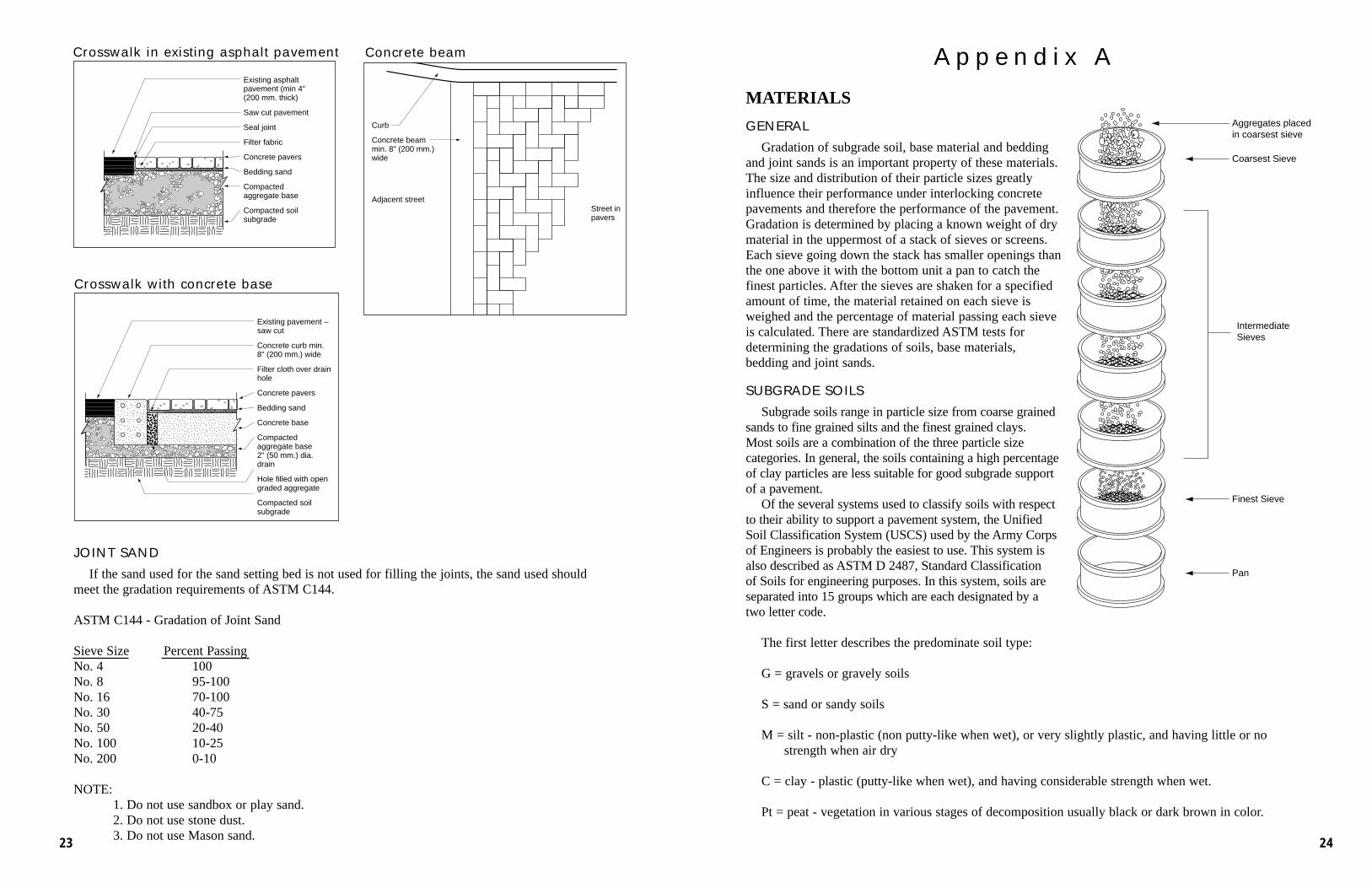
Concrete beam
Crosswalk with concrete base
Curb
Concrete beam min. 8" (200 mm.) wide
Adjacent streetStreet in pavers
Existing pavement – saw cut
Concrete curb min. 8" (200 mm.) wide
Filter cloth over drain hole
Concrete pavers
Bedding sand
Concrete base
Compacted aggregate base 2" (50 mm.) dia. drain
Hole filled with open graded aggregate
Compacted soil subgrade
Crosswalk in existing asphalt pavement
Existing asphalt pavement (min 4" (200 mm. thick)
Saw cut pavement
Seal joint
Filter fabric
Concrete pavers
Bedding sand
Compacted aggregate base
Compacted soil subgrade
JOINT SAND
If the sand used for the sand setting bed is not used for filling the joints, the sand used shouldmeet the gradation requirements of ASTM C144.
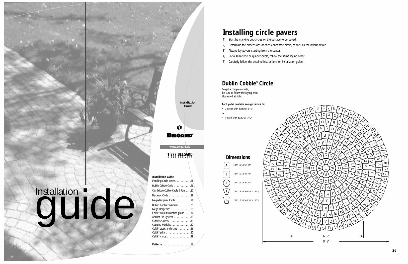
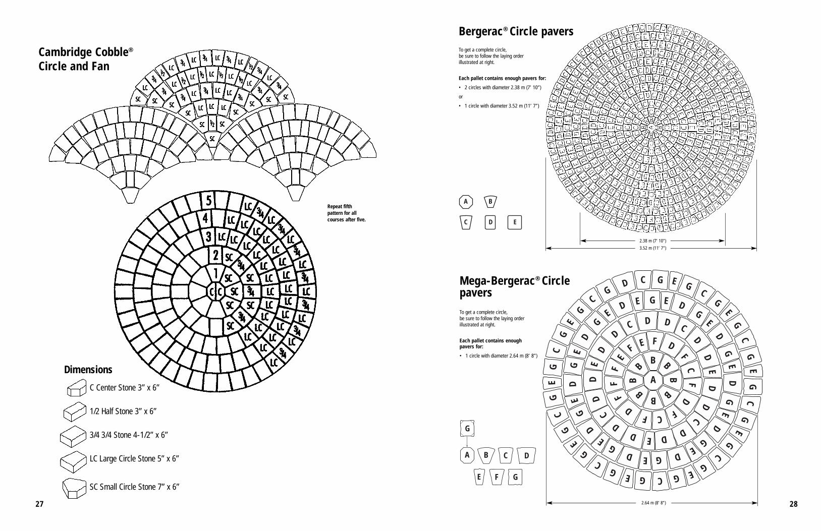
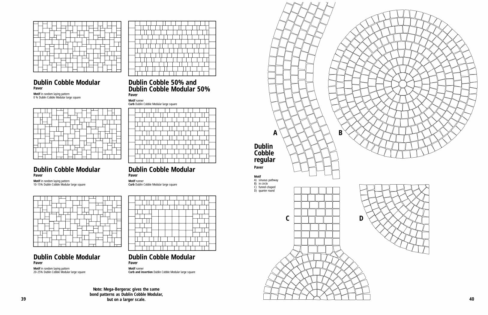
Bergerac® Circle paversTo get a complete circle,be sure to follow the laying orderillustrated at right.
Each pallet contains enough pavers for:
• 2 circles with diameter 2.38 m (7’ 10”)
or
• 1 circle with diameter 3.52 m (11’ 7”)
2.38 m (7’ 10”)
3.52 m (11’ 7”)
Mega-Bergerac® Circle paversTo get a complete circle,be sure to follow the laying orderillustrated at right.
Each pallet contains enough pavers for:
• 1 circle with diameter 2.64 m (8’ 8”)
2.64 m (8’ 8”)
Repeat fifthpattern for allcourses after five.
Dimensions
C Center Stone 3” x 6”
1/2 Half Stone 3” x 6”
3/4 3/4 Stone 4-1/2” x 6”
LC Large Circle Stone 5” x 6”
SC Small Circle Stone 7” x 6”
Cambridge Cobble®
Circle and Fan
3029
A
B
C
Dublin Cobble Modular“Large square” pavers
Dublin Cobble ModularThree basic pavers
Mega-BergeracThree basic pavers
Mega-Bergerac“Large square” pavers
Pallet packingDublin Cobble Modular and Mega-Bergerac pavers are packed in pairs of pallets, providing great flexibility depending on the chosenlaying proportion.
A blend of Dublin Cobble standard pavers and Dublin CobbleModular pavers gives even more flexibility in terms of paversize and, consequently, more interesting bond patterns.
IMPORTANT: A blend of Dublin Cobble standardpavers and Dublin Cobble Modular pavers can be laidin a running bond pattern only.
Dublin Cobble Modular
Dublin Cobble standard
Dublin Cobble ModularDublin Cobble standard
Dublin Cobble standard
Dublin Cobble standard
Dublin Cobble Modular
2 3/8” x 5 7/8” x 3”
2 3/8” x 5 7/8” x 5 1/8”
2 3/8” x 5 7/8” x 5 7/8”
2 3/8” x 5 7/8” x 6 3/4”
2 3/8” x 5 7/8” x 7 3/8”
2 3/8” x 5 7/8” x 8 7/8”
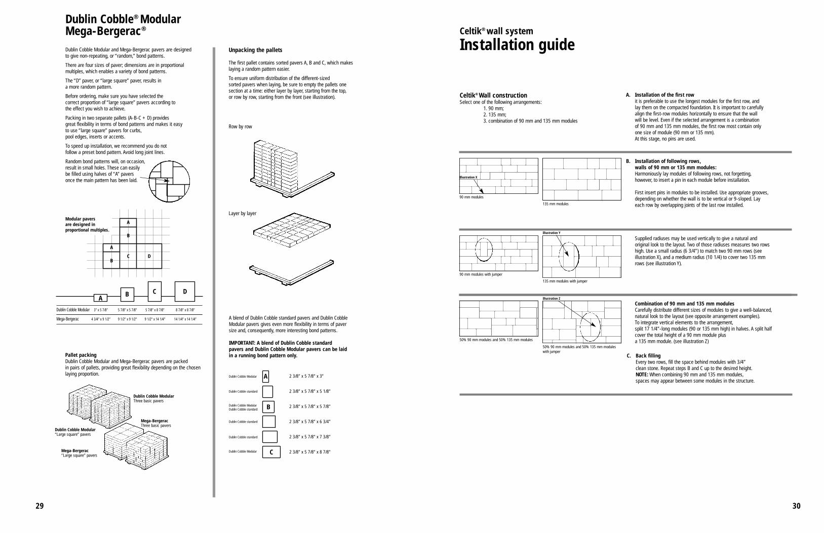
Celtik® wall system
Installation guide
Celtik® Wall constructionSelect one of the following arrangements:
1. 90 mm;2. 135 mm;3. combination of 90 mm and 135 mm modules
A. Installation of the first rowit is preferable to use the longest modules for the first row, and lay them on the compacted foundation. It is important to carefully align the first-row modules horizontally to ensure that the wall will be level. Even if the selected arrangement is a combination of 90 mm and 135 mm modules, the first row most contain only one size of module (90 mm or 135 mm).At this stage, no pins are used.
90 mm modules
135 mm modules
90 mm modules with jumper
135 mm modules with jumper
50% 90 mm modules and 50% 135 mm modules
50% 90 mm modules and 50% 135 mm moduleswith jumper
Combination of 90 mm and 135 mm modulesCarefully distribute different sizes of modules to give a well-balanced,natural look to the layout (see opposite arrangement examples).To integrate vertical elements to the arrangement,split 17 1/4”-long modules (90 or 135 mm high) in halves. A split halfcover the total height of a 90 mm module plus a 135 mm module. (see illustration Z)
B. Installation of following rows,walls of 90 mm or 135 mm modules:Harmoniously lay modules of following rows, not forgetting,however, to insert a pin in each module before installation.
First insert pins in modules to be installed. Use appropriate grooves,depending on whether the wall is to be vertical or 9-sloped. Layeach row by overlapping joints of the last row installed.
Supplied radiuses may be used vertically to give a natural andoriginal look to the layout. Two of those radiuses measures two rowshigh. Use a small radius (6 3/4”) to match two 90 mm rows (seeillustration X), and a medium radius (10 1/4) to cover two 135 mmrows (see illustration Y).
Illustration X
Illustration Y
Illustration Z
A
B
C D
A
B
A B C D
Dublin Cobble® ModularMega-Bergerac®
Dublin Cobble Modular and Mega-Bergerac pavers are designed to give non-repeating, or “random,” bond patterns.
There are four sizes of paver; dimensions are in proportionalmultiples, which enables a variety of bond patterns.
The “D” paver, or “large square” paver, results in a more random pattern.
Before ordering, make sure you have selected the correct proportion of “large square” pavers according to the effect you wish to achieve.
Packing in two separate pallets (A-B-C + D) provides great flexibility in terms of bond patterns and makes it easy to use “large square” pavers for curbs,pool edges, inserts or accents.
To speed up installation, we recommend you do not follow a preset bond pattern. Avoid long joint lines.
Random bond patterns will, on occasion,result in small holes. These can easily be filled using halves of “A” pavers once the main pattern has been laid.
Modular pavers are designed in proportional multiples.
Dublin Cobble Modular 3” x 5 7/8” 5 7/8” x 5 7/8” 5 7/8” x 8 7/8” 8 7/8” x 8 7/8”
Mega-Bergerac 4 3/4” x 9 1/2” 9 1/2” x 9 1/2” 9 1/2” x 14 1/4” 14 1/4” x 14 1/4”
Unpacking the pallets
The first pallet contains sorted pavers A, B and C, which makeslaying a random pattern easier.
To ensure uniform distribution of the different-sized sorted pavers when laying, be sure to empty the pallets onesection at a time: either layer by layer, starting from the top,or row by row, starting from the front (see illustration).
Row by row
Layer by layer
C. Back fillingEvery two rows, fill the space behind modules with 3/4”clean stone. Repeat steps B and C up to the desired height.NOTE: When combining 90 mm and 135 mm modules,spaces may appear between some modules in the structure.
3231
Celtik® wall system
Installation guide
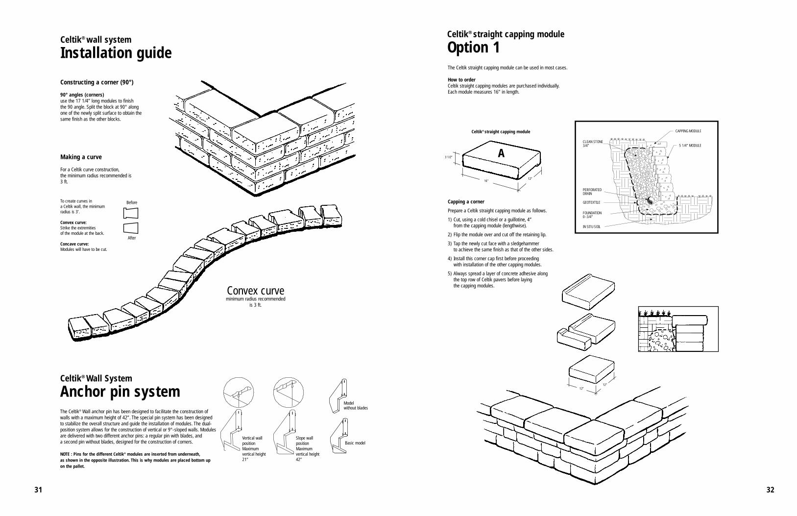
Constructing a corner (90°)
90° angles (corners)use the 17 1/4” long modules to finish the 90 angle. Split the block at 90° alongone of the newly split surface to obtain thesame finish as the other blocks.
Making a curve
For a Celtik curve construction,the minimum radius recommended is 3 ft.
To create curves in a Celtik wall, the minimum radius is 3’.
Convex curve:Strike the extremities of the module at the back.
Concave curve:Modules will have to be cut.
Before
After
Convex curveminimum radius recommended
is 3 ft.
A3 1/2”
16”12”
12”12”
Celtik® straight capping module
Option 1The Celtik straight capping module can be used in most cases.
How to orderCeltik straight capping modules are purchased individually.Each module measures 16” in length.
Celtik® straight capping module
Capping a corner
Prepare a Celtik straight capping module as follows.
1) Cut, using a cold chisel or a guillotine, 4”from the capping module (lengthwise).
2) Flip the module over and cut off the retaining lip.
3) Tap the newly cut face with a sledgehammer to achieve the same finish as that of the other sides.
4) Install this corner cap first before proceeding with installation of the other capping modules.
5) Always spread a layer of concrete adhesive alongthe top row of Celtik pavers before laying the capping modules.
CAPPING MODULE
CLEAN STONE3/4”
GEOTEXTILE
PERFORATEDDRAIN
FOUNDATION0–3/4”
IN SITU SOIL
5 1/4” MODULE
The Celtik® Wall anchor pin has been designed to facilitate the construction ofwalls with a maximum height of 42”. The special pin system has been designedto stabilize the overall structure and guide the installation of modules. The dual-position system allows for the construction of vertical or 9°-sloped walls. Modulesare delivered with two different anchor pins: a regular pin with blades, and a second pin without blades, designed for the construction of corners.
NOTE : Pins for the different Celtik® modules are inserted from underneath,as shown in the opposite illustration. This is why modules are placed bottom upon the pallet.
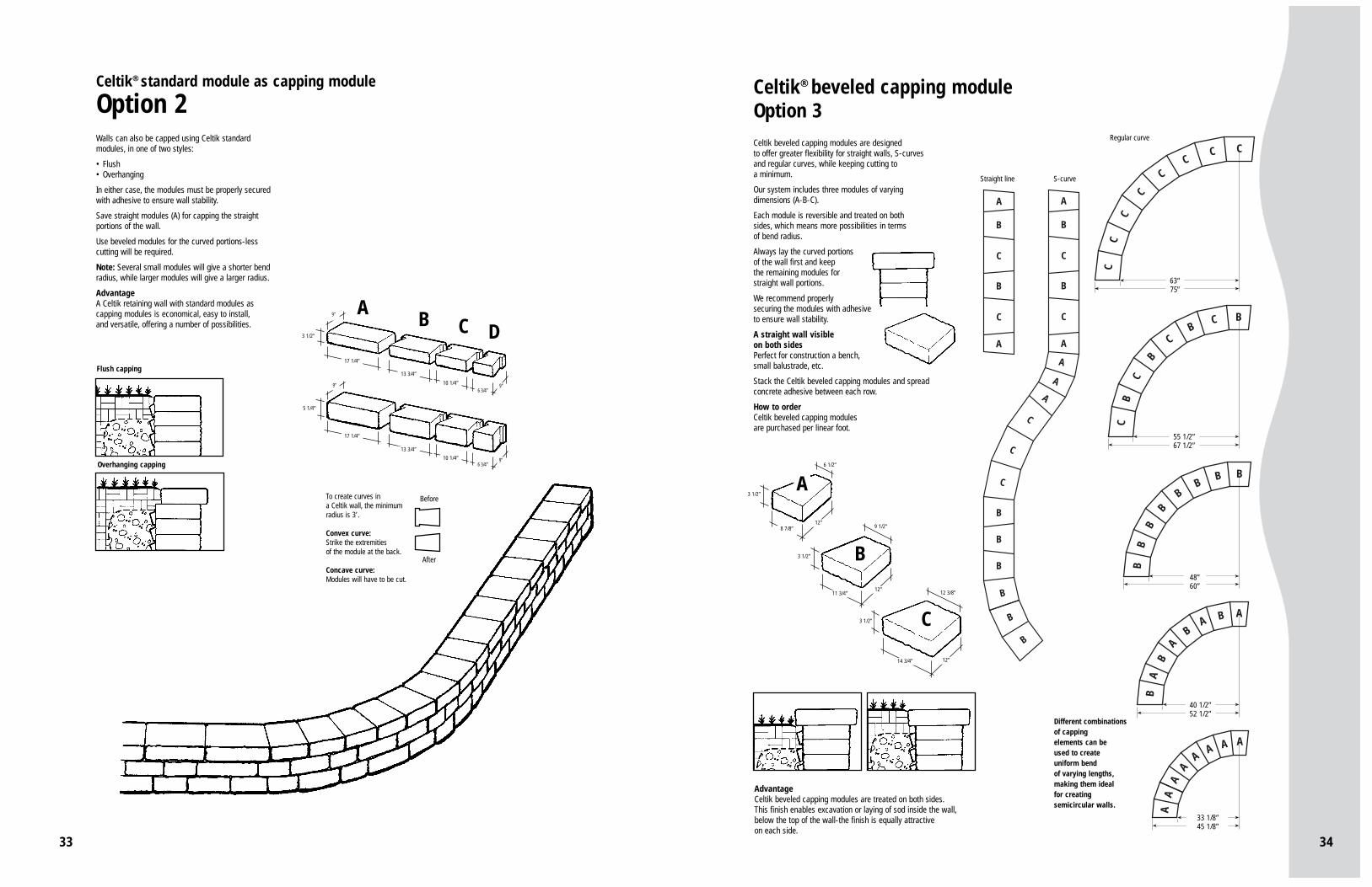
Celtik® beveled capping moduleOption 3Celtik beveled capping modules are designed to offer greater flexibility for straight walls, S-curvesand regular curves, while keeping cutting to a minimum.
Our system includes three modules of varying dimensions (A-B-C).
Each module is reversible and treated on both sides, which means more possibilities in terms of bend radius.
Always lay the curved portions of the wall first and keepthe remaining modules forstraight wall portions.
We recommend properly securing the modules with adhesiveto ensure wall stability.
A straight wall visible on both sidesPerfect for construction a bench,small balustrade, etc.
Stack the Celtik beveled capping modules and spread concrete adhesive between each row.
How to orderCeltik beveled capping modules are purchased per linear foot.
Straight line S-curve
Regular curve
Different combinationsof capping elements can be used to create uniform bendof varying lengths,making them ideal for creatingsemicircular walls.
AdvantageCeltik beveled capping modules are treated on both sides.This finish enables excavation or laying of sod inside the wall,below the top of the wall-the finish is equally attractive on each side.
A B C D3 1/2”
17 1/4”
13 3/4”
10 1/4”6 3/4”
9”
9”
5 1/4”
17 1/4”
13 3/4”
10 1/4”6 3/4”
9”
9”
Walls can also be capped using Celtik standardmodules, in one of two styles:
• Flush• Overhanging
In either case, the modules must be properly secured with adhesive to ensure wall stability.
Save straight modules (A) for capping the straight portions of the wall.
Use beveled modules for the curved portions-less cutting will be required.
Note: Several small modules will give a shorter bend radius, while larger modules will give a larger radius.
AdvantageA Celtik retaining wall with standard modules ascapping modules is economical, easy to install,and versatile, offering a number of possibilities.
Flush capping
To create curves in a Celtik wall, the minimum radius is 3’.
Convex curve:Strike the extremities of the module at the back.
Concave curve:Modules will have to be cut.
Before
After
Celtik® standard module as capping module
Option 2
Overhanging capping
3635
Capping module
Module 3 1/2”
Module 3 1/2”Capping module
Module 3 1/2”
Module 3 1/2”Capping module
Module 3 1/2”
Module 3 1/2”
Paver
180 mm(7”)
12”
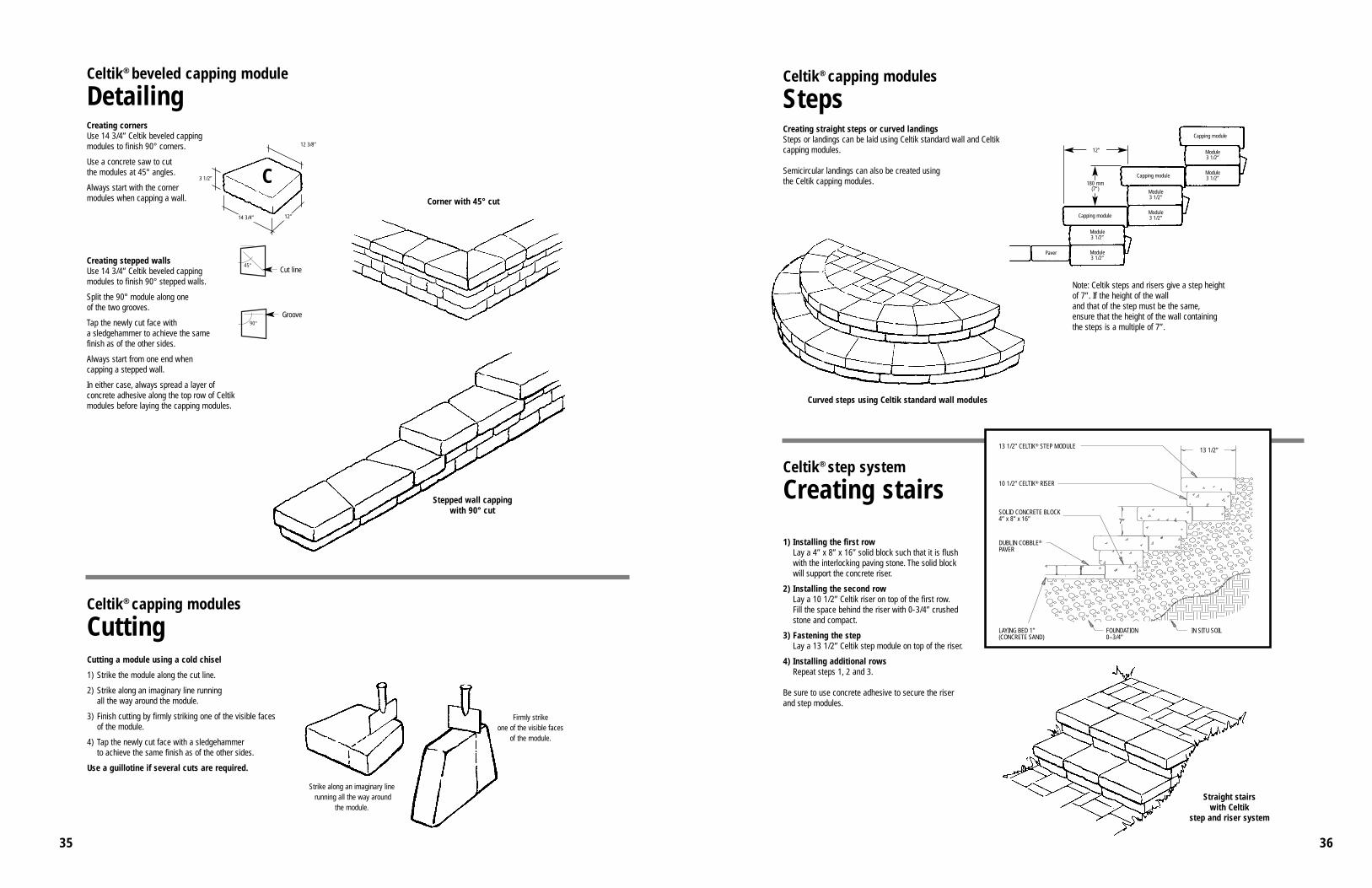
Celtik® step system
Creating stairs
1) Installing the first rowLay a 4” x 8” x 16” solid block such that it is flush with the interlocking paving stone. The solid block will support the concrete riser.
2) Installing the second rowLay a 10 1/2” Celtik riser on top of the first row.Fill the space behind the riser with 0-3/4” crushed stone and compact.
3) Fastening the stepLay a 13 1/2” Celtik step module on top of the riser.
4) Installing additional rowsRepeat steps 1, 2 and 3.
Be sure to use concrete adhesive to secure the riser and step modules.
Celtik® capping modules
Steps
Straight stairs with Celtik
step and riser system
Curved steps using Celtik standard wall modules
Creating straight steps or curved landingsSteps or landings can be laid using Celtik standard wall and Celtikcapping modules.
Semicircular landings can also be created using the Celtik capping modules.
Note: Celtik steps and risers give a step height of 7”. If the height of the wall and that of the step must be the same,ensure that the height of the wall containing the steps is a multiple of 7”.
Split the 90° module along one of the two grooves.
Tap the newly cut face with a sledgehammer to achieve the same finish as of the other sides.
Always start from one end when capping a stepped wall.
In either case, always spread a layer of concrete adhesive along the top row of Celtikmodules before laying the capping modules.
45°
C
90°
3 1/2”
12”14 3/4”
12 3/8”
Celtik® beveled capping module
Detailing
Corner with 45° cut
Stepped wall cappingwith 90° cut
Cut line
Celtik® capping modules
CuttingCutting a module using a cold chisel
1) Strike the module along the cut line.
2) Strike along an imaginary line running all the way around the module.
3) Finish cutting by firmly striking one of the visible faces of the module.
4) Tap the newly cut face with a sledgehammer to achieve the same finish as of the other sides.
Use a guillotine if several cuts are required.
Strike along an imaginary linerunning all the way around
the module.
Firmly strike one of the visible faces
of the module.
Groove
3837
D
C
DA B C
29”29”
Pillar may be capped using Celtik
capping modules
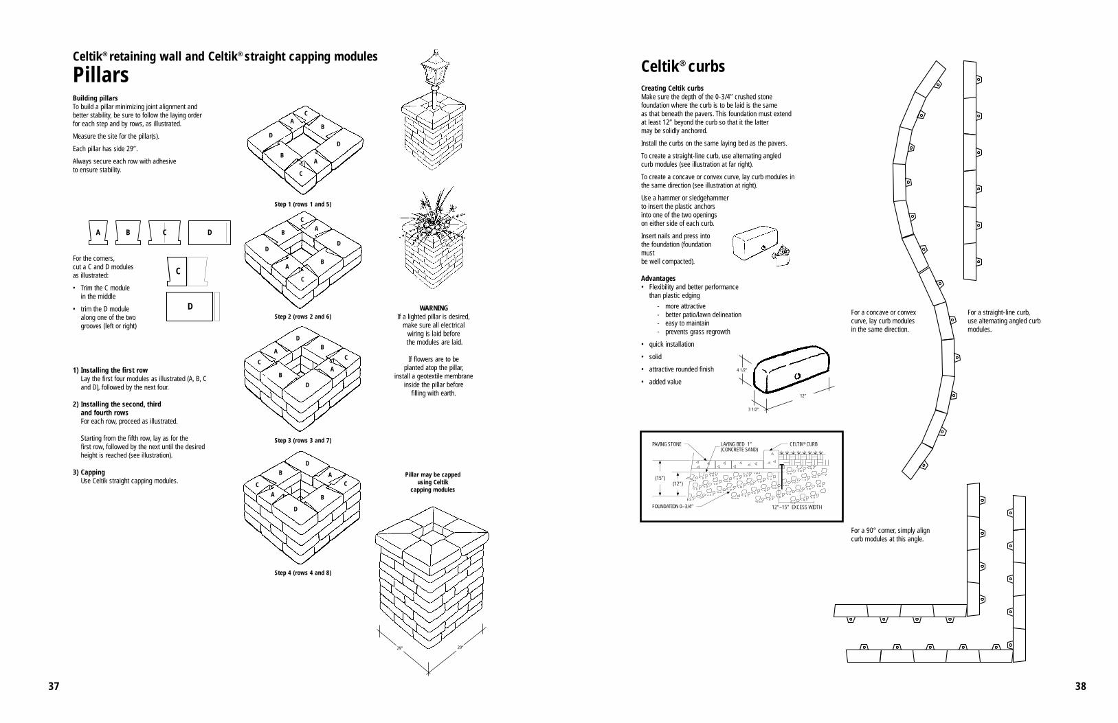
Celtik® retaining wall and Celtik® straight capping modules
PillarsBuilding pillarsTo build a pillar minimizing joint alignment and better stability, be sure to follow the laying order for each step and by rows, as illustrated.
Measure the site for the pillar(s).
Each pillar has side 29”.
Always secure each row with adhesive to ensure stability.
WARNINGIf a lighted pillar is desired,
make sure all electrical wiring is laid beforethe modules are laid.
If flowers are to be planted atop the pillar,
install a geotextile membraneinside the pillar before
filling with earth.
For the corners,cut a C and D modulesas illustrated:
• Trim the C module in the middle
• trim the D module along one of the two grooves (left or right)
1) Installing the first rowLay the first four modules as illustrated (A, B, Cand D), followed by the next four.
2) Installing the second, third and fourth rowsFor each row, proceed as illustrated.
Starting from the fifth row, lay as for the first row, followed by the next until the desiredheight is reached (see illustration).
3) CappingUse Celtik straight capping modules.
AC
B
DD
A
C
B
D
AC
B
A
C
B
D
A
C
BD
A
C
B
D
A
C
B
D
AC
B
D
Step 1 (rows 1 and 5)
Step 2 (rows 2 and 6)
Step 3 (rows 3 and 7)
Step 4 (rows 4 and 8)
Creating Celtik curbsMake sure the depth of the 0-3/4” crushed stone foundation where the curb is to be laid is the same as that beneath the pavers. This foundation must extend at least 12” beyond the curb so that it the latter may be solidly anchored.
Install the curbs on the same laying bed as the pavers.
To create a straight-line curb, use alternating angled curb modules (see illustration at far right).
To create a concave or convex curve, lay curb modules in the same direction (see illustration at right).
Use a hammer or sledgehammer to insert the plastic anchors into one of the two openingson either side of each curb.
Insert nails and press into the foundation (foundationmust be well compacted).
Advantages• Flexibility and better performance
than plastic edging
- more attractive- better patio/lawn delineation- easy to maintain- prevents grass regrowth
• quick installation
• solid
• attractive rounded finish
• added value
4 1/2”
12”
3 1/2”
Celtik® curbs
For a 90° corner, simply align curb modules at this angle.
For a concave or convexcurve, lay curb modules in the same direction.
CELTIK® CURBLAYING BED 1”(CONCRETE SAND)
PAVING STONE
(15”)(12”)
FOUNDATION 0–3/4” 12”–15” EXCESS WIDTH
For a straight-line curb,use alternating angled curbmodules.
4039
Dublin Cobble ModularPaver Motif in random laying pattern20-25% Dublin Cobble Modular large square
Dublin Cobble ModularPaver Motif in random laying pattern10-15% Dublin Cobble Modular large square
Dublin Cobble Modular PaverMotif in random laying pattern0 % Dublin Cobble Modular large square
Dublin Cobble ModularPaver Motif runner Curb and insertion Dublin Cobble Modular large square
Congratulations for selecting Belgard as your new pavement. Your choice constitutes a wise investmentadding aesthetic and monetary value to your property while providing long term savings through durability and low maintenance.
The Belgard pavers incorporated in your pavement are made to exacting standards and are guaranteedas long as you own the property, provided that the pavement has been installed by an AuthorizedBelgard Contractor actively participating in the Belgard program.
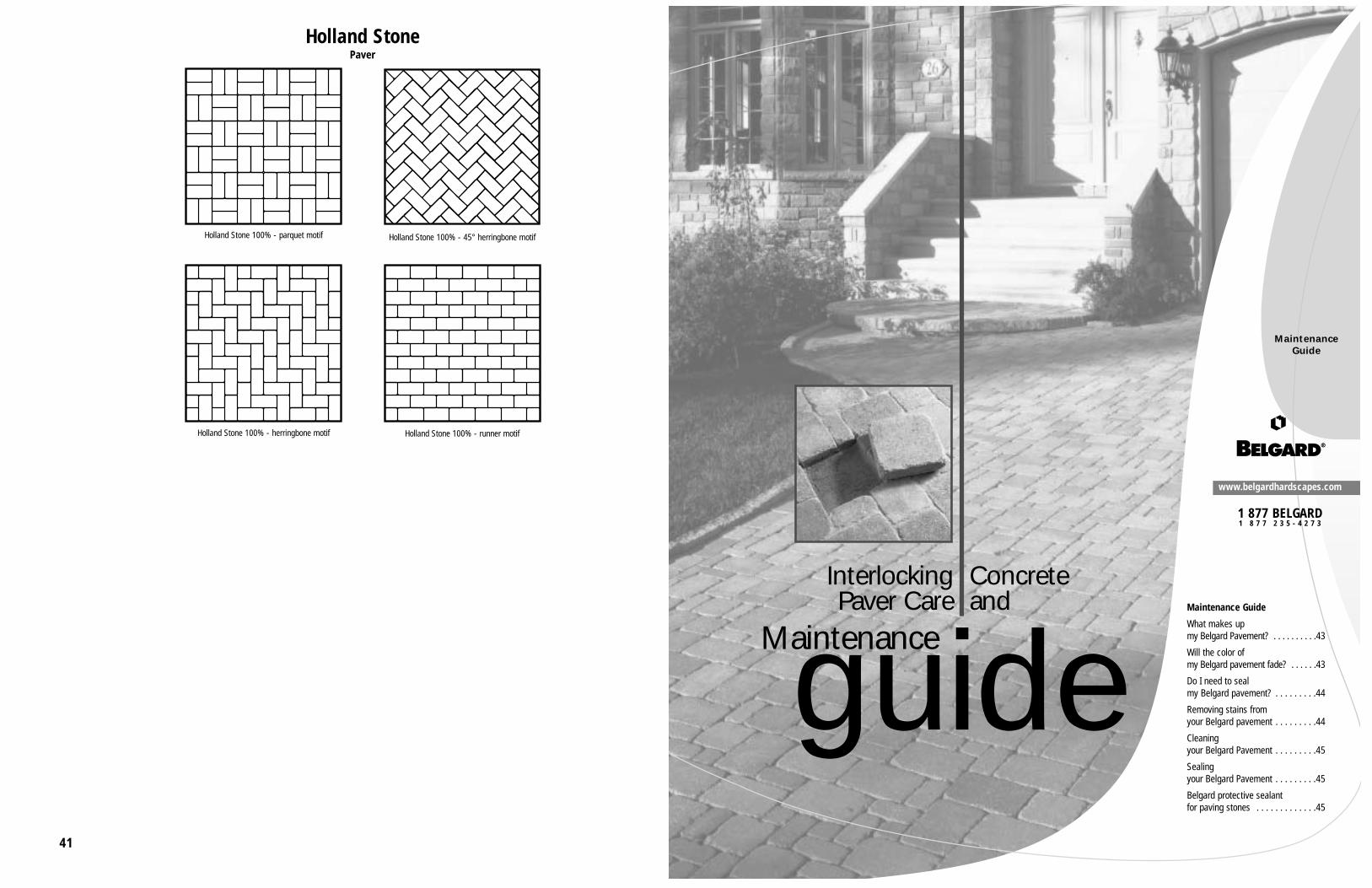
WHAT MAKES UP MY BELGARD PAVEMENT?
The successful combination of attractive, durable pavers, high quality support materials and the craftsmanship of an Authorized Belgard Contractor makes Belgard Interlocking Pavement Systems the best choice for your paving needs.
We manufacture Belgard concrete pavers in the most modern facilities to the exacting requirements of ASTM C936. This is the same standard which all commercial and industrial interlocking concretepavers must meet. The Interlocking Concrete Pavement Institute certifies that all Belgard pavers comply with ASTM C936.
The material used by your Authorized Belgard Contractor to construct the base of your pavement mustmeet the standards of your state governing graded aggregate material. The bedding sand must complywith ASTM C33 or ASTM C144.
The Authorized Belgard Contractor who installed your pavement underwent training to use the propermaterials and to construct your pavement using the guidelines and recommendations of the InterlockingConcrete Pavement Institute. Your Authorized Belgard Contractor takes pride in his workmanship andprovides you with a guarantee of his workmanship for a period of 5 years.
The Belgard interlocking concrete pavers used in your pavement are extremely durable. We manufacture our pavers using specific sands, crushed stone, cement, water and color fast pigmentswhich provide most of the color. A computer operated machine, especially designed for the purpose,forms the concrete mixture into the shapes used in your pavement. We manufacture most Belgardpavers with a beveled edge around the top of the paver. The bevel, or chamfer, ensures that there is notripping hazard if a paver happens to be slightly higher or lower than its neighbors. The chamfer alsoreduces the chance for chipping of the paver edge. You will notice that the surface of your paver isslightly coarse to the touch. This texture is to provide a safe non-slip walking or driving surface evenwhen wet. The very dense structure of the paver minimizes the amount of moisture which can penetrateand cause damage during freeze cycles.
The contractor places the pavers in a sand setting bed surrounded by an edge restraint which keeps thedesired uniform joint spaces between pavers and prevents the edge pavers from moving outward. Thesand used to fill the joint spaces provides vertical interlock between pavers and allows the pavement tobehave as a strong but flexible mat. Your Belgard Pavement features superior aesthetic value and farless maintenance than competing pavements.
WILL THE COLOR OF MY BELGARD PAVEMENT FADE?
The color of your Belgard Pavement is a combination of the pigmented cement paste which holds thesand and aggregate particles together, and the natural color of the sand and aggregate particlesthemselves. When we manufacture our pavers, some of the pigmented paste covers the sand andaggregate particles at the surface of the pavers. A combination of the installation process, use andweathering over the first year or two will remove that paste from some of the particle surfaces,
resulting in a mellowing of the overall appearance of the pavement in much the same way as fine woodachieves a patina with age. The exposure of some of the sand and aggregate particles not only adds tothe character of the pavement but also can enhance the slip resistance.
We use synthetic iron oxide pigments, in all our Belgard pavers, which are very stable and fade resistant. A perception of fading can occur when the phenomenon called efflorescence takes place.Efflorescence results when water soluble salts within the pavers are brought to the surface by moisture,then react with air to form small crystals on the paver surface. Efflorescence can manifest itself as aslight haze or a white powder like coating. The phenomenon is quite common in most concrete products and some clay products especially those which incorporate mortar in their structure.Efflorescence is not harmful in any way and it is recommended that you allow the weathering processto effect removal. If for some reason you wish to hasten the process, you may follow the procedureslisted in the section on cleaning.
DO I NEED TO SEAL MY BELGARD PAVEMENT?
Your Belgard Pavement is a durable pavement and very resistant to the damage that spilled fuels or de-icing materials may cause to other paving systems. Sealing is not necessary to preserve the strength ordurability of your Belgard Pavement.
You may use a sealer to “deepen” the color tone of your pavement or give it a “wet look”.
Recommended sealers can help protect the appearance of your Belgard Pavement from oil leaks, tire marks or spilled liquids and foods.
Consult the section on Sealing before sealing your Belgard Pavement.
REMOVING STAINS FROM YOUR BELGARD PAVEMENT
If you plan to seal your pavement, it is best to first remove any stains then clean the pavement prior tosealing.
Following is a list of common stains and the procedure used to remove them. The list has been takenfrom Interlocking Concrete Pavement Institute Tech Spec Number 5. In all cases, follow recommendedprocedures and practices and use the proper personal protection equipment.
Asphalt and Emulsified Asphalt - Chill with ice (if warm outside) then scrape away as much as possible. For large areas use Belgard Paint, Tar and Rubber remover as directed. For smaller areas use Belgard Sealant Remover.
Cutback Asphalt and Roofing Tar - Use Belgard Paint, Tar and Rubber Remover as directed.
Blood, Candy, Ketchup, Mustard, Food Stains - Apply liquid detergent full strength and allow it topenetrate for 20-30 minutes. Scrub and rinse with hot water. Removal is easier if you treat the stainsimmediately.
Caulking and Chewing Gum - Chill with ice then scrape off as much as possible. Make a poultice(paste) of talcum powder and denatured alcohol. Scrub area with poultice and stiff brush then rinse with hot water and strong detergent. If the caulking is acrylic latex, use Belgard Oil, Paint and SealerRemover as directed.
Clay Soil - Scrape off dry material then scrub with detergent and rinse with hot water.
Leaf, Wood Rot and Tobacco - Apply household bleach and scrub with stiff bristled brush and rinse.
4645
Mortar - Let harden then carefully remove hardened spots with a trowel, putty knife or chisel. Thenclean with Belgard Efflorescence Cleaner.
Oil and Grease - Mop up excess with rags or paper towels. Cover area with cat litter and allow to stay24 hours. Change litter when it begins to look saturated. Remove litter and treat area with Belgard Dirtand Grease Cleaner.
Paint, fresh - Sop up all paint possible without wiping. If the paint is water based latex, soak and thenscrub the area with hot water, scouring powder and a stiff brush until improvement ceases. Let dry and treat as for dried paint.
Paint, dried - Treat with Belgard Oil, Paint and Sealer Remover as directed. A commercial paintremover may be used. Apply a liberal coat and allow to sit for 20-30 minutes. Gently scrub area toloosen paint. Do not rub loosened paint into paver surface or allow to spread. Blot up loosened paintand remover.
Rust - Treat with Belgard Rust Remover as directed.
Tire Marks - Scrub black area with water, detergent and scouring powder. Rinse with water. If tiremarks remain after several attempts, treat area with Belgard Oil, Paint and Sealer Remover.
CLEANING YOUR BELGARD PAVEMENT
You can remove most dirt and grime from your Belgard Pavement by washing it off with the gardenhose or a combination water spray and a stiff bristle broom. If stains are present on your pavement,remove before cleaning.
You can remove efflorescence, ground-in dirt and some mortar smears effectively with BelgardEfflorescence Cleaner, available from your Authorized Belgard Dealer. Be sure to follow the directionscarefully and use the recommended personal protection equipment such as eye protection and plastic orrubber gloves.
SEALING YOUR BELGARD PAVEMENT
You should never seal your Belgard Pavement until at least 60 days after installation. It is better to waitfor a year. The time interval between installation and sealing allows the pavement to mellow and anyefflorescence to rise to the surface and be removed with Belgard Efflorescence Remover. Prior tosealing any Belgard Pavement, remove stains, thoroughly clean, then let pavement and joint sand fully dry. Re-sweep joints with sand if necessary.
BELGARD PROTECTIVE SEALANT FOR PAVING STONES
A solvent based sealer protects against oil and dirt and makes routine cleaning easier. This product enhances the paver color and gives the surface a wet look but does not make the pavement slippery.
Prepare the pavement and apply Belgard Protective Sealant for Paving Stones as directed.