Seats and Restraint Systems ........................... 1-1 Front Seats ............................................... 1-3 Rear Seats ............................................... 1-7 Safety Belts ............................................. 1-22 Child Restraints ....................................... 1-42 Airbag System ......................................... 1-72 Restraint System Check ............................ 1-87 Features and Controls ..................................... 2-1 Keys ........................................................ 2-3 Doors and Locks ...................................... 2-11 Windows ................................................. 2-24 Theft-Deterrent Systems ............................ 2-27 Starting and Operating Your Vehicle ........... 2-31 Mirrors .................................................... 2-43 OnStar ® System ...................................... 2-44 HomeLink ® Wireless Control System ........... 2-46 Storage Areas ......................................... 2-51 Instrument Panel ............................................. 3-1 Instrument Panel Overview .......................... 3-4 Climate Controls ...................................... 3-25 Warning Lights, Gages, and Indicators ........ 3-31 Driver Information Center (DIC) .................. 3-45 Audio System(s) ....................................... 3-76 Driving Your Vehicle ....................................... 4-1 Your Driving, the Road, and Your Vehicle ..... 4-2 Towing ................................................... 4-39 Service and Appearance Care .......................... 5-1 Service ..................................................... 5-3 Fuel ......................................................... 5-5 Checking Things Under the Hood ............... 5-10 All-Wheel Drive ........................................ 5-44 Bulb Replacement .................................... 5-46 Windshield Wiper Blade Replacement ......... 5-50 Tires ...................................................... 5-51 Appearance Care ..................................... 5-85 Vehicle Identification ................................. 5-94 Electrical System ...................................... 5-95 Capacities and Specifications ................... 5-101 Maintenance Schedule ..................................... 6-1 Maintenance Schedule ................................ 6-2 Customer Assistance and Information .............. 7-1 Customer Assistance and Information ........... 7-2 Reporting Safety Defects ........................... 7-10 Index ................................................................ 1 2005 Chevrolet Uplander Owner Manual M
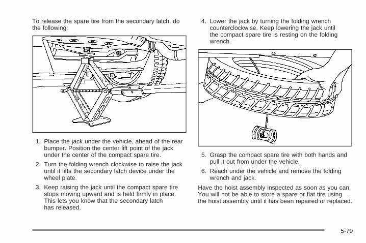
Transcript
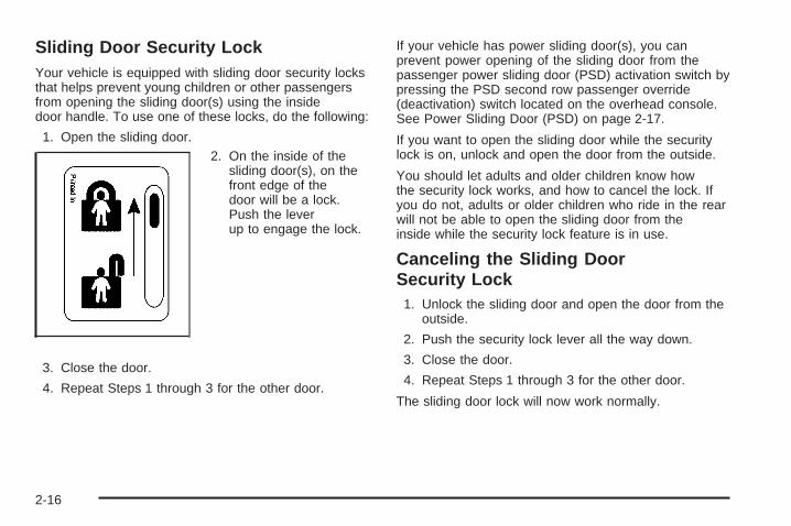
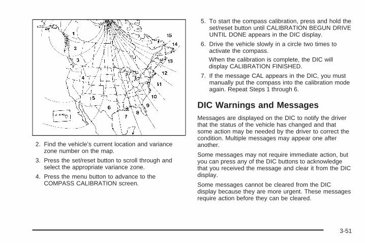
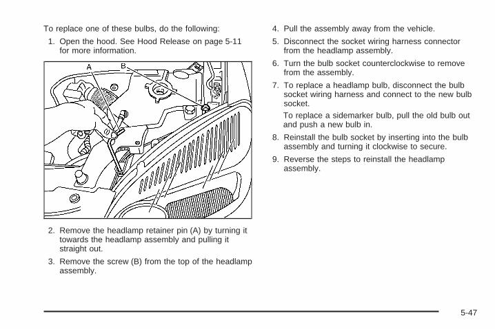
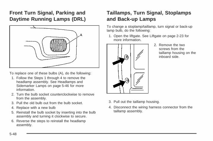
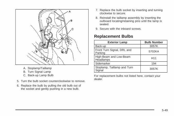
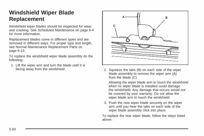
Seats and Restraint Systems ........................... 1-1Front Seats ............................................... 1-3Rear Seats ............................................... 1-7Safety Belts ............................................. 1-22Child Restraints ....................................... 1-42Airbag System ......................................... 1-72Restraint System Check ............................ 1-87
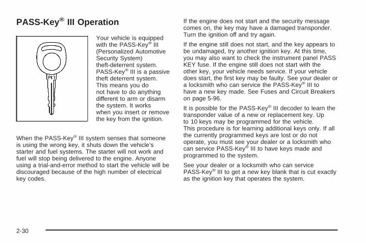
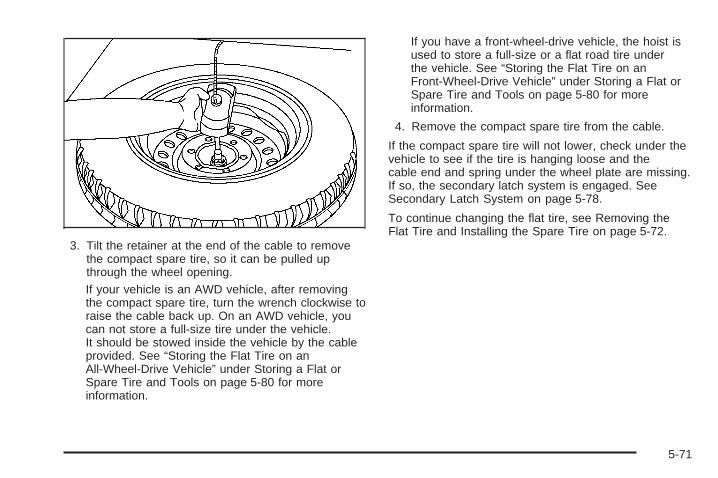
Features and Controls ..................................... 2-1Keys ........................................................ 2-3Doors and Locks ...................................... 2-11Windows ................................................. 2-24Theft-Deterrent Systems ............................ 2-27Starting and Operating Your Vehicle ........... 2-31Mirrors .................................................... 2-43OnStar® System ...................................... 2-44HomeLink® Wireless Control System ........... 2-46Storage Areas ......................................... 2-51
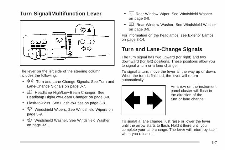
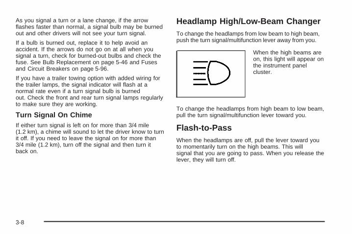
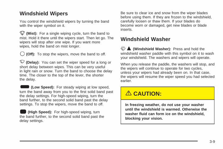
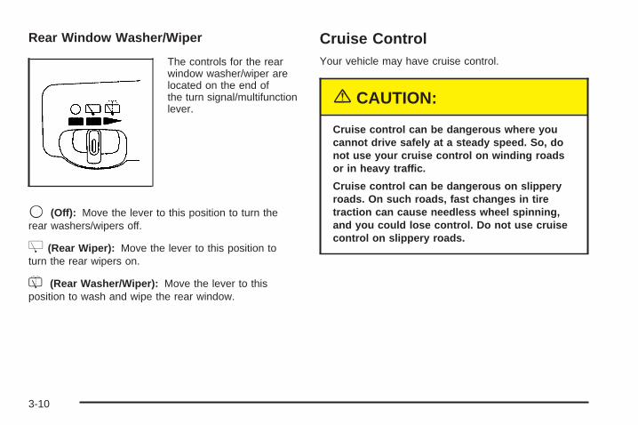
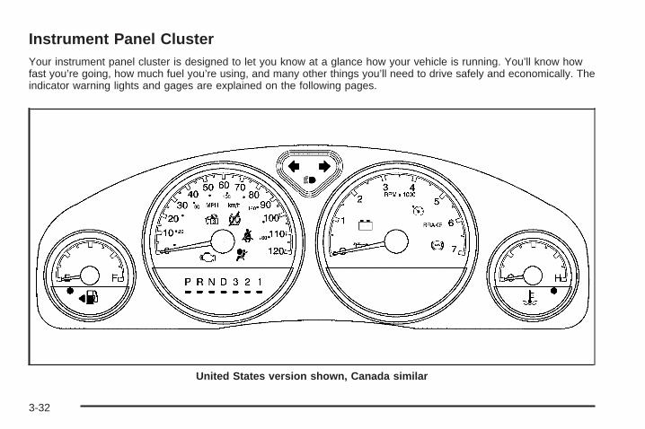
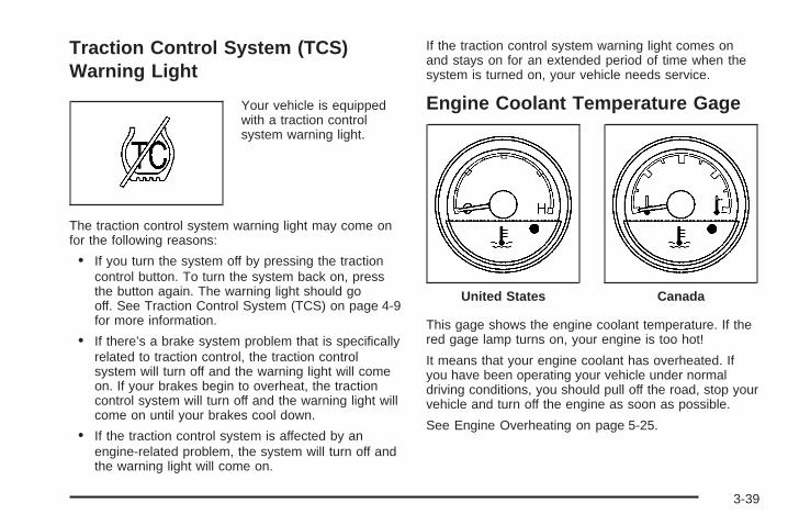
Instrument Panel ............................................. 3-1Instrument Panel Overview .......................... 3-4Climate Controls ...................................... 3-25Warning Lights, Gages, and Indicators ........ 3-31Driver Information Center (DIC) .................. 3-45Audio System(s) ....................................... 3-76
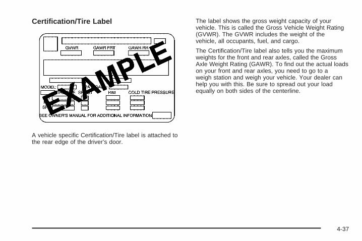
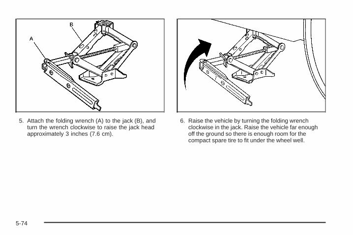
Driving Your Vehicle ....................................... 4-1Your Driving, the Road, and Your Vehicle ..... 4-2Towing ................................................... 4-39
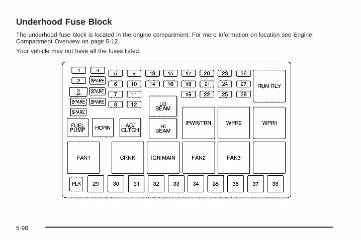
Service and Appearance Care .......................... 5-1Service ..................................................... 5-3Fuel ......................................................... 5-5Checking Things Under the Hood ............... 5-10All-Wheel Drive ........................................ 5-44Bulb Replacement .................................... 5-46Windshield Wiper Blade Replacement ......... 5-50Tires ...................................................... 5-51Appearance Care ..................................... 5-85Vehicle Identification ................................. 5-94Electrical System ...................................... 5-95Capacities and Specifications ................... 5-101
Customer Assistance and Information .............. 7-1Customer Assistance and Information ........... 7-2Reporting Safety Defects ........................... 7-10
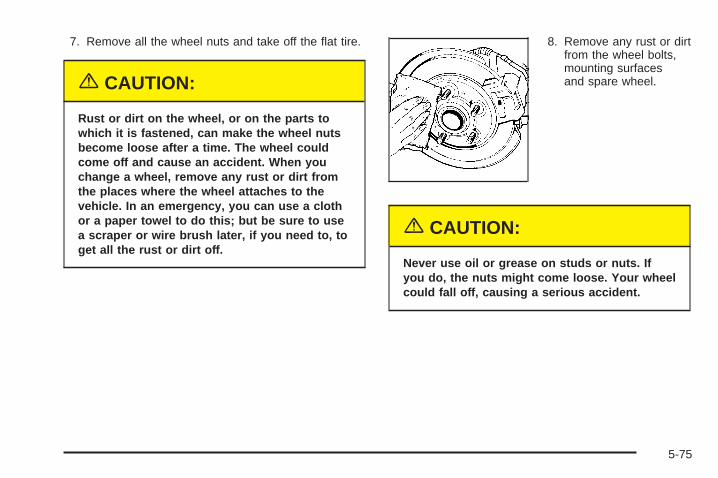
Index ................................................................ 1
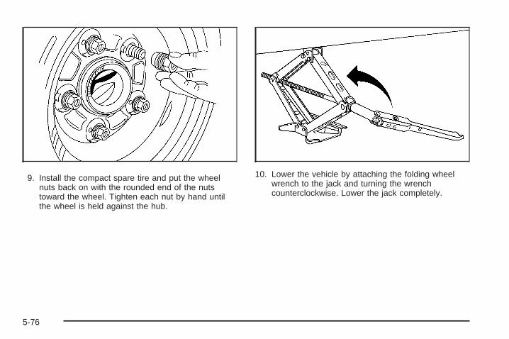
2005 Chevrolet Uplander Owner Manual M
GENERAL MOTORS, GM, the GM Emblem,CHEVROLET, and the CHEVROLET Emblem areregistered trademarks; and the name UPLANDER is atrademark of General Motors Corporation.
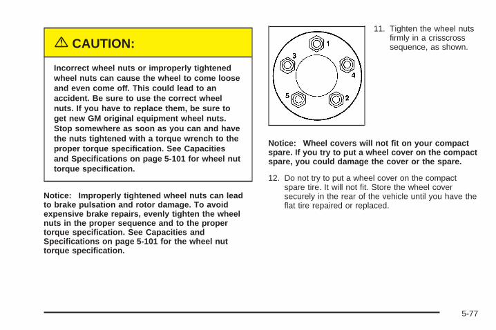
This manual includes the latest information at the time itwas printed. We reserve the right to make changesafter that time without further notice. For vehicles firstsold in Canada, substitute the name “General Motors ofCanada Limited” for Chevrolet Motor Division wheneverit appears in this manual.
Keep this manual in the vehicle, so it will be there if it isever needed when you are on the road. If the vehicleis sold, leave this manual in the vehicle.
Canadian OwnersA French language copy of this manual can be obtainedfrom your dealer or from:
Helm, IncorporatedP.O. Box 07130Detroit, MI 48207
How to Use This ManualMany people read the owner manual from beginning toend when they first receive their new vehicle. If thisis done, it can help you learn about the featuresand controls for the vehicle. Pictures and words worktogether in the owner manual to explain things.
IndexA good place to quickly locate information about thevehicle is the Index in the back of the manual. It is analphabetical list of what is in the manual and thepage number where it can be found.
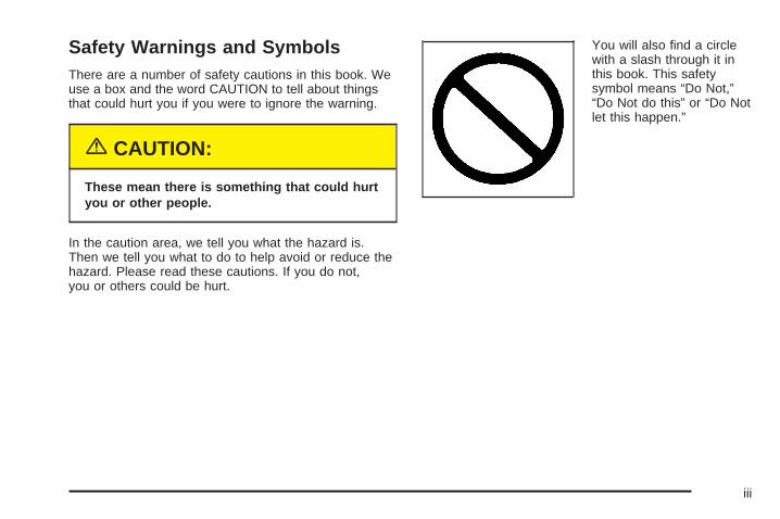
Safety Warnings and SymbolsThere are a number of safety cautions in this book. Weuse a box and the word CAUTION to tell about thingsthat could hurt you if you were to ignore the warning.
{CAUTION:
These mean there is something that could hurtyou or other people.
In the caution area, we tell you what the hazard is.Then we tell you what to do to help avoid or reduce thehazard. Please read these cautions. If you do not,you or others could be hurt.
You will also find a circlewith a slash through it inthis book. This safetysymbol means “Do Not,”“Do Not do this” or “Do Notlet this happen.”
iii
Vehicle Damage WarningsAlso, in this manual you will find these notices:
Notice: These mean there is something that coulddamage your vehicle.
A notice tells about something that can damage thevehicle. Many times, this damage would not be coveredby your vehicle’s warranty, and it could be costly. Butthe notice will tell what to do to help avoid the damage.
When you read other manuals, you might seeCAUTION and NOTICE warnings in different colors or indifferent words.
There are also warning labels on the vehicle. They usethe same words, CAUTION or NOTICE.
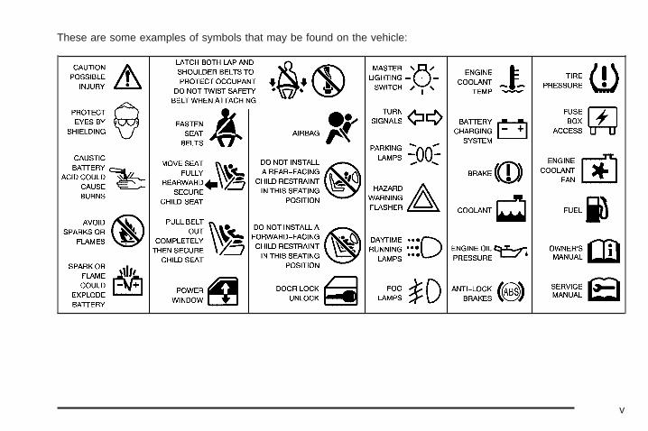
Vehicle SymbolsThe vehicle has components and labels that usesymbols instead of text. Symbols are shown along withthe text describing the operation or informationrelating to a specific component, control, message,gage, or indicator.
If you need help figuring out a specific name of acomponent, gage, or indicator, reference the followingtopics:
• Seats and Restraint Systems in Section 1
• Features and Controls in Section 2
• Instrument Panel Overview in Section 3
• Climate Controls in Section 3
• Warning Lights, Gages, and Indicators in Section 3
• Audio System(s) in Section 3
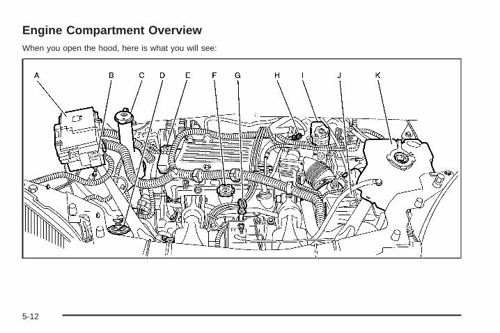
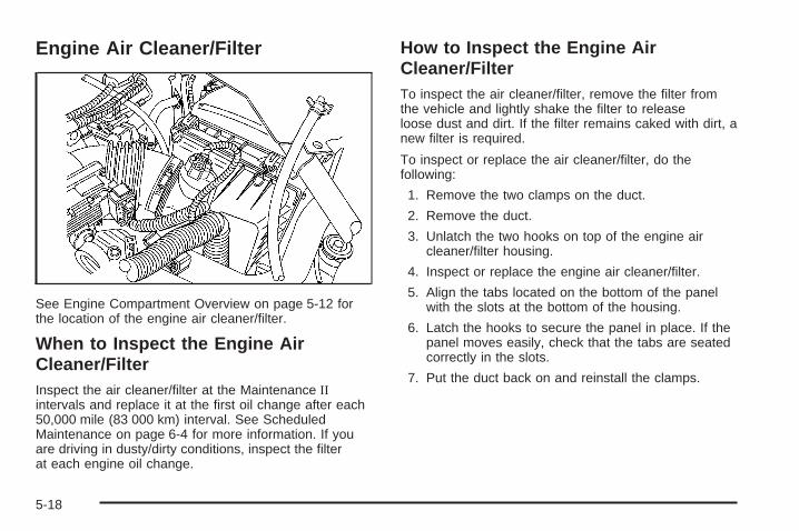
• Engine Compartment Overview in Section 5
iv
These are some examples of symbols that may be found on the vehicle:
v
✍ NOTES
vi
Front Seats ......................................................1-3Manual Seats ................................................1-3Six-Way Power Seats .....................................1-4Heated Seats .................................................1-4Reclining Seatbacks ........................................1-5Head Restraints .............................................1-7
Safety Belts ...................................................1-22Safety Belts: They Are for Everyone ................1-22Questions and Answers About Safety Belts ......1-26How to Wear Safety Belts Properly .................1-27Driver Position ..............................................1-27Shoulder Belt Height Adjustment .....................1-35Safety Belt Use During Pregnancy ..................1-36Right Front Passenger Position .......................1-36Rear Seat Passengers ..................................1-36
Rear Safety Belt Comfort Guides forChildren and Small Adults ..........................1-39
Safety Belt Pretensioners ...............................1-41Safety Belt Extender .....................................1-42
Child Restraints .............................................1-42Older Children ..............................................1-42Infants and Young Children ............................1-45Child Restraint Systems .................................1-48Where to Put the Restraint .............................1-51Top Strap ....................................................1-52Top Strap Anchor Location .............................1-53Lower Anchorages and Top Tethers for
Children (LATCH System) ...........................1-54Securing a Child Restraint Designed for
the LATCH System ....................................1-56Securing a Child Restraint in a Rear
Seat Position ............................................1-56Securing a Child Restraint in the Right
Front Seat Position ....................................1-58Built-In Child Restraint ...................................1-62
Section 1 Seats and Restraint Systems
1-1
Airbag System ...............................................1-72Where Are the Airbags? ................................1-74When Should an Airbag Inflate? .....................1-77What Makes an Airbag Inflate? .......................1-78How Does an Airbag Restrain? .......................1-78What Will You See After an Airbag Inflates? .....1-79Passenger Sensing System ............................1-80
Servicing Your Airbag-Equipped Vehicle ...........1-85Adding Equipment to Your Airbag-Equipped
Vehicle ....................................................1-86Restraint System Check ..................................1-87
Checking the Restraint Systems ......................1-87Replacing Restraint System Parts After a
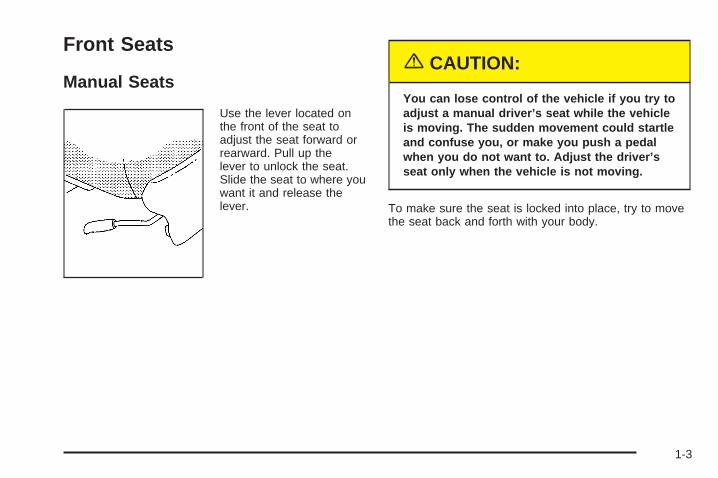
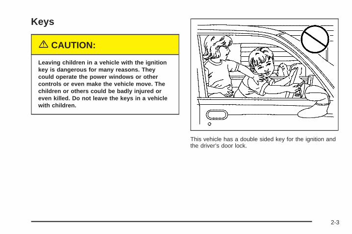
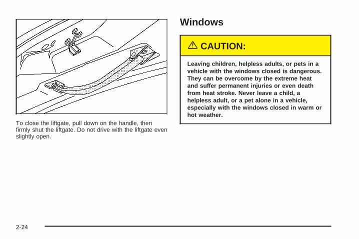
Use the lever located onthe front of the seat toadjust the seat forward orrearward. Pull up thelever to unlock the seat.Slide the seat to where youwant it and release thelever.
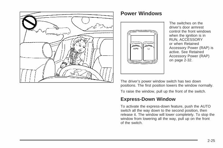
{CAUTION:
You can lose control of the vehicle if you try toadjust a manual driver’s seat while the vehicleis moving. The sudden movement could startleand confuse you, or make you push a pedalwhen you do not want to. Adjust the driver’sseat only when the vehicle is not moving.
To make sure the seat is locked into place, try to movethe seat back and forth with your body.
1-3
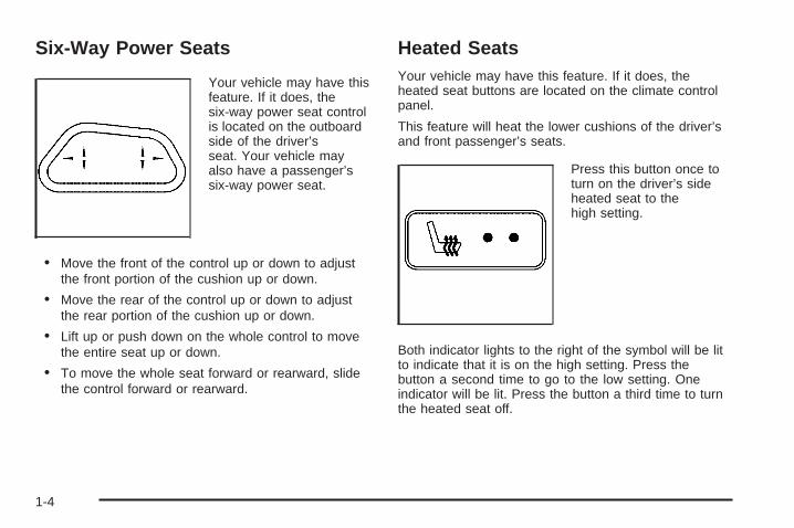
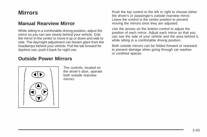
Six-Way Power Seats
Your vehicle may have thisfeature. If it does, thesix-way power seat controlis located on the outboardside of the driver’sseat. Your vehicle mayalso have a passenger’ssix-way power seat.
• Move the front of the control up or down to adjustthe front portion of the cushion up or down.
• Move the rear of the control up or down to adjustthe rear portion of the cushion up or down.
• Lift up or push down on the whole control to movethe entire seat up or down.
• To move the whole seat forward or rearward, slidethe control forward or rearward.
Heated SeatsYour vehicle may have this feature. If it does, theheated seat buttons are located on the climate controlpanel.
This feature will heat the lower cushions of the driver’sand front passenger’s seats.
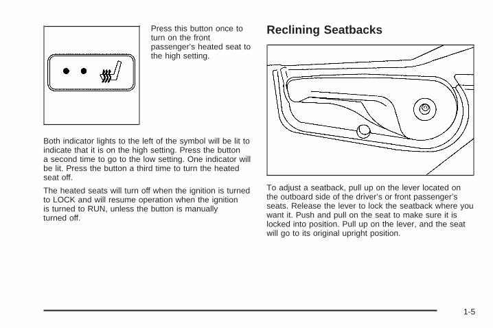
Press this button once toturn on the driver’s sideheated seat to thehigh setting.
Both indicator lights to the right of the symbol will be litto indicate that it is on the high setting. Press thebutton a second time to go to the low setting. Oneindicator will be lit. Press the button a third time to turnthe heated seat off.
1-4
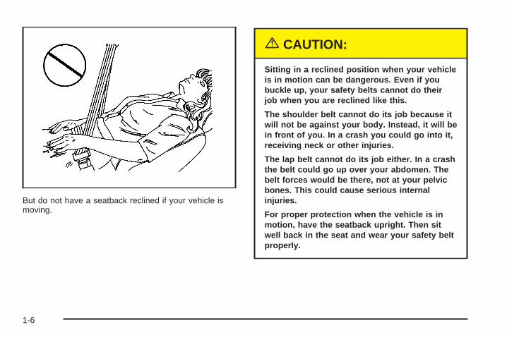
Press this button once toturn on the frontpassenger’s heated seat tothe high setting.
Both indicator lights to the left of the symbol will be lit toindicate that it is on the high setting. Press the buttona second time to go to the low setting. One indicator willbe lit. Press the button a third time to turn the heatedseat off.
The heated seats will turn off when the ignition is turnedto LOCK and will resume operation when the ignitionis turned to RUN, unless the button is manuallyturned off.
Reclining Seatbacks
To adjust a seatback, pull up on the lever located onthe outboard side of the driver’s or front passenger’sseats. Release the lever to lock the seatback where youwant it. Push and pull on the seat to make sure it islocked into position. Pull up on the lever, and the seatwill go to its original upright position.
1-5
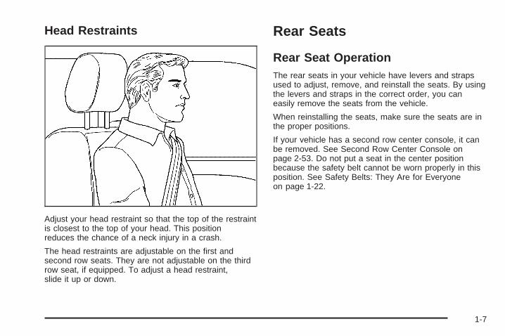
But do not have a seatback reclined if your vehicle ismoving.
{CAUTION:
Sitting in a reclined position when your vehicleis in motion can be dangerous. Even if youbuckle up, your safety belts cannot do theirjob when you are reclined like this.
The shoulder belt cannot do its job because itwill not be against your body. Instead, it will bein front of you. In a crash you could go into it,receiving neck or other injuries.
The lap belt cannot do its job either. In a crashthe belt could go up over your abdomen. Thebelt forces would be there, not at your pelvicbones. This could cause serious internalinjuries.
For proper protection when the vehicle is inmotion, have the seatback upright. Then sitwell back in the seat and wear your safety beltproperly.
1-6
Head Restraints
Adjust your head restraint so that the top of the restraintis closest to the top of your head. This positionreduces the chance of a neck injury in a crash.
The head restraints are adjustable on the first andsecond row seats. They are not adjustable on the thirdrow seat, if equipped. To adjust a head restraint,slide it up or down.
Rear Seats
Rear Seat OperationThe rear seats in your vehicle have levers and strapsused to adjust, remove, and reinstall the seats. By usingthe levers and straps in the correct order, you caneasily remove the seats from the vehicle.
When reinstalling the seats, make sure the seats are inthe proper positions.
If your vehicle has a second row center console, it canbe removed. See Second Row Center Console onpage 2-53. Do not put a seat in the center positionbecause the safety belt cannot be worn properly in thisposition. See Safety Belts: They Are for Everyoneon page 1-22.
1-7
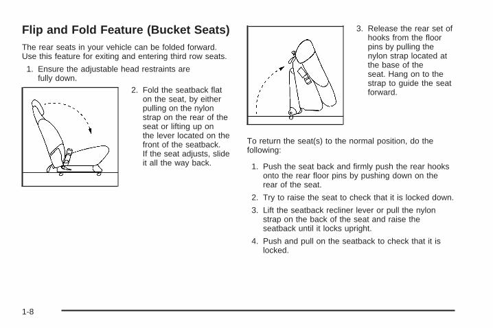
Flip and Fold Feature (Bucket Seats)The rear seats in your vehicle can be folded forward.Use this feature for exiting and entering third row seats.
1. Ensure the adjustable head restraints arefully down.
2. Fold the seatback flaton the seat, by eitherpulling on the nylonstrap on the rear of theseat or lifting up onthe lever located on thefront of the seatback.If the seat adjusts, slideit all the way back.
3. Release the rear set ofhooks from the floorpins by pulling thenylon strap located atthe base of theseat. Hang on to thestrap to guide the seatforward.
To return the seat(s) to the normal position, do thefollowing:
1. Push the seat back and firmly push the rear hooksonto the rear floor pins by pushing down on therear of the seat.
2. Try to raise the seat to check that it is locked down.
3. Lift the seatback recliner lever or pull the nylonstrap on the back of the seat and raise theseatback until it locks upright.
4. Push and pull on the seatback to check that it islocked.
1-8
Bucket SeatsIf your vehicle has the bucket seats, the seatbacks canbe folded down or reclined. The seats can also beadjusted forward or rearward, or removed.
One of the bucket seats may be equipped with a built-inchild restraint. See Built-In Child Restraint on page 1-62.
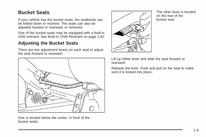
Adjusting the Bucket SeatsThere are two adjustment levers on each seat to adjustthe seat forward or rearward.
One is located below the center, in front of thebucket seats.
The other lever is locatedon the rear of thebucket seat.
Lift up either lever and slide the seat forward orrearward.
Release the lever. Push and pull on the seat to makesure it is locked into place.
1-9
Folding or Reclining the Seatbacks
{CAUTION:
If the seatback is not locked, it could moveforward in a sudden stop or crash. That couldcause injury to the person sitting there. Alwayspress rearward on the seatback to be sure it islocked.
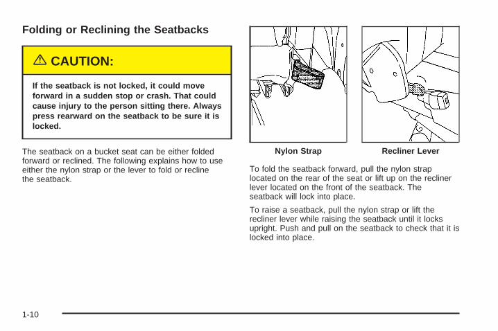
The seatback on a bucket seat can be either foldedforward or reclined. The following explains how to useeither the nylon strap or the lever to fold or reclinethe seatback.
To fold the seatback forward, pull the nylon straplocated on the rear of the seat or lift up on the reclinerlever located on the front of the seatback. Theseatback will lock into place.
To raise a seatback, pull the nylon strap or lift therecliner lever while raising the seatback until it locksupright. Push and pull on the seatback to check that it islocked into place.
Nylon Strap Recliner Lever
1-10
To recline the seatback, pull the nylon strap or lift therecliner lever. Press back on the seatback until youreach the desired position, then let go of the strap orlever.
To return the seatback to an upright position, pull on thenylon strap or lift the recliner lever without putting anypressure on the seatback. Push and pull on theseatback to be sure it is locked into place.
Removing the Bucket SeatsMake sure the seatback is in the upright position. Thehead restraints should be fully down.
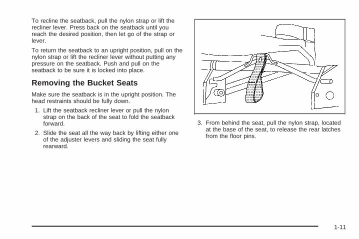
1. Lift the seatback recliner lever or pull the nylonstrap on the back of the seat to fold the seatbackforward.
2. Slide the seat all the way back by lifting either oneof the adjuster levers and sliding the seat fullyrearward.
3. From behind the seat, pull the nylon strap, locatedat the base of the seat, to release the rear latchesfrom the floor pins.
1-11
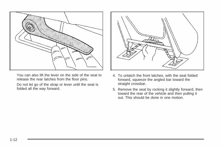
You can also lift the lever on the side of the seat torelease the rear latches from the floor pins.Do not let go of the strap or lever until the seat isfolded all the way forward.
4. To unlatch the front latches, with the seat foldedforward, squeeze the angled bar toward thestraight crossbar.
5. Remove the seat by rocking it slightly forward, thentoward the rear of the vehicle and then pulling itout. This should be done in one motion.
1-12
Replacing the Bucket Seats
{CAUTION:
If the seatback is not locked, it could moveforward in a sudden stop or crash. That couldcause injury to the person sitting there. Alwayspress rearward on the seatback to be sure it islocked.
{CAUTION:
A seat that is not locked into place properlycan move around in a collision or sudden stop.People in the vehicle could be injured. Be sureto lock the seat into place properly wheninstalling it.
{CAUTION:
A safety belt that is improperly routed, notproperly attached, or twisted will not providethe protection needed in a crash. The personwearing the belt could be seriously injured.After installing the seat, always check to besure that the safety belts are properly routedand attached, and are not twisted.
Do not put the seats in so they face rearward becausethey will not latch that way. If you want more storageroom behind the seat, adjust the seat by sliding itforward.
Make sure the seats are in the full rear position beforebeginning this procedure.
1. With the seat folded, squeeze the angled bartoward the straight crossbar while placing thefront hooks of the bucket seat onto the front twofloor pins.
1-13
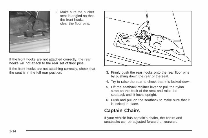
2. Make sure the bucketseat is angled so thatthe front hooksclear the floor pins.
If the front hooks are not attached correctly, the rearhooks will not attach to the rear set of floor pins.
If the front hooks are not attaching correctly, check thatthe seat is in the full rear position. 3. Firmly push the rear hooks onto the rear floor pins
by pushing down the rear of the seat.
4. Try to raise the seat to check that it is locked down.
5. Lift the seatback recliner lever or pull the nylonstrap on the back of the seat and raise theseatback until it locks upright.
6. Push and pull on the seatback to make sure that itis locked in place.
Captain ChairsIf your vehicle has captain’s chairs, the chairs andseatbacks can be adjusted forward or rearward.
1-14
Adjusting the Captain’s Chairs(Second Row)The second row captain’s chairs can be adjustedforward or rearward.
There are two manual adjustment bars on each seat.One is located under the front of the seat cushion. Theother one is located under the rear of the seatcushion.
Lift up either bar to slide the seat forward or rearward.Release the lever. Push and pull on the seat tomake sure it is locked into place.
Folding or Reclining the Seatbacks
{CAUTION:
If the seatback is not locked, it could moveforward in a sudden stop or crash. That couldcause injury to the person sitting there. Alwayspress rearward on the seatback to be sure it islocked.
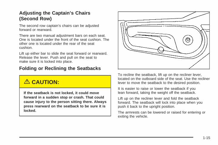
To recline the seatback, lift up on the recliner lever,located on the outboard side of the seat. Use the reclinerlever to move the seatback to the desired position.
It is easier to raise or lower the seatback if youlean forward, taking the weight off the seatback.
Lift up on the recliner lever and fold the seatbackforward. The seatback will lock into place when youpush it back to the upright position.
The armrests can be lowered or raised for entering orexiting the vehicle.
1-15
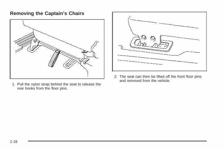
Removing the Captain’s Chairs
1. Pull the nylon strap behind the seat to release therear hooks from the floor pins.
2. The seat can then be lifted off the front floor pinsand removed from the vehicle.
1-16
Replacing the Captain’s Chairs
{CAUTION:
If the seatback is not locked, it could moveforward in a sudden stop or crash. That couldcause injury to the person sitting there. Alwayspress rearward on the seatback to be sure it islocked.
{CAUTION:
A seat that is not locked into place properlycan move around in a collision or sudden stop.People in the vehicle could be injured. Be sureto lock the seat into place properly wheninstalling it.
{CAUTION:
A safety belt that is improperly routed, notproperly attached, or twisted will not providethe protection needed in a crash. The personwearing the belt could be seriously injured.After installing the seat, always check to besure that the safety belts are properly routedand attached, and are not twisted.
Do not put the seats in so they face rearward becausethey will not latch that way. For the second row, ifyou want more storage room behind the seat, adjust theseat by sliding it forward.
Make sure the seatbacks are in the upright position, theseat belts are on the correct side of the seats andthe seats are in the full rear position before beginningthis procedure.
1-17
1. Hook the front latches over the front floor pins. 2. Push the rear of the seat down to lock the rearlatches onto the rear set of floor pins.
3. Push and pull on the seat to be sure it is properlyattached.
1-18
Third Row SeatYour vehicle may have a third row seat. It is a fullbench seat and may come with the convenience center.See Convenience Center on page 2-56 for moreinformation. The third row seat can be removed andreplaced, or with the seatback folded, it will lie flat withthe convenience center.
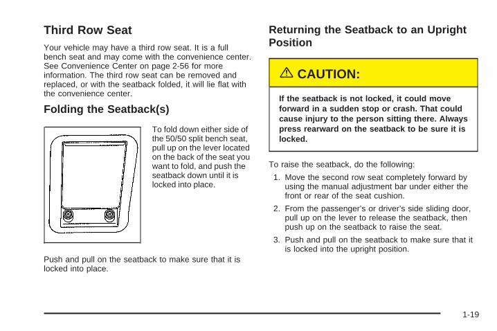
Folding the Seatback(s)
To fold down either side ofthe 50/50 split bench seat,pull up on the lever locatedon the back of the seat youwant to fold, and push theseatback down until it islocked into place.
Push and pull on the seatback to make sure that it islocked into place.
Returning the Seatback to an UprightPosition
{CAUTION:
If the seatback is not locked, it could moveforward in a sudden stop or crash. That couldcause injury to the person sitting there. Alwayspress rearward on the seatback to be sure it islocked.
To raise the seatback, do the following:
1. Move the second row seat completely forward byusing the manual adjustment bar under either thefront or rear of the seat cushion.
2. From the passenger’s or driver’s side sliding door,pull up on the lever to release the seatback, thenpush up on the seatback to raise the seat.
3. Push and pull on the seatback to make sure that itis locked into the upright position.
1-19
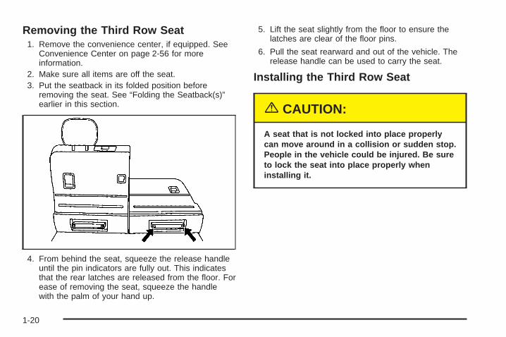
Removing the Third Row Seat1. Remove the convenience center, if equipped. See
Convenience Center on page 2-56 for moreinformation.
2. Make sure all items are off the seat.3. Put the seatback in its folded position before
removing the seat. See “Folding the Seatback(s)”earlier in this section.
4. From behind the seat, squeeze the release handleuntil the pin indicators are fully out. This indicatesthat the rear latches are released from the floor. Forease of removing the seat, squeeze the handlewith the palm of your hand up.
5. Lift the seat slightly from the floor to ensure thelatches are clear of the floor pins.
6. Pull the seat rearward and out of the vehicle. Therelease handle can be used to carry the seat.
Installing the Third Row Seat
{CAUTION:
A seat that is not locked into place properlycan move around in a collision or sudden stop.People in the vehicle could be injured. Be sureto lock the seat into place properly wheninstalling it.
1-20
{CAUTION:
A safety belt that is improperly routed, notproperly attached, or twisted will not providethe protection needed in a crash. The personwearing the belt could be seriously injured.After installing the seat, always check to besure that the safety belts are properly routedand attached, and are not twisted.
Do not put the third row seat in so it faces rearwardbecause it will not latch that way. The seat has to go inbefore the convenience center. See ConvenienceCenter on page 2-56 for more information.
For ease of installing the seat, put the seat in the foldedposition before beginning this procedure.
1. From the rear of the vehicle, place the front hooksof the seat onto the front floor pins in the third row.To do this, the seat will need to be angledapproximately 8-10 inches (20-25 cm) from the floorso the front hooks clear the rear floor pins andrear floor cups. Use the release handle to guide theseat into place.
If the front hooks are not attached correctly, therear latches will not attach to the rear set offloor pins.
2. Firmly push the rear latches into the rear floor pinsby pushing down on the rear of the seat.
3. Try to raise the seat to make sure that it is lockeddown. The indicator pins will no longer stick outwhen the seat is properly latched into place.
{CAUTION:
If the seatback is not locked, it could moveforward in a sudden stop or crash. That couldcause injury to the person sitting there. Alwayspress rearward on the seatback to be sure it islocked.
4. Return the seatback to its upright position. See“Returning the Seatback to an Upright Position”earlier in this section.
1-21
Safety Belts
Safety Belts: They Are for EveryoneThis part of the manual tells you how to use safetybelts properly. It also tells you some things you shouldnot do with safety belts.
{CAUTION:
Do not let anyone ride where he or she can notwear a safety belt properly. If you are in acrash and you are not wearing a safety belt,your injuries can be much worse. You can hitthings inside the vehicle or be ejected from it.You can be seriously injured or killed. In thesame crash, you might not be, if you arebuckled up. Always fasten your safety belt,and check that your passengers’ belts arefastened properly too.
{CAUTION:
It is extremely dangerous to ride in a cargoarea, inside or outside of a vehicle. In acollision, people riding in these areas are morelikely to be seriously injured or killed. Do notallow people to ride in any area of your vehiclethat is not equipped with seats and safetybelts. Be sure everyone in your vehicle is in aseat and using a safety belt properly.
Your vehicle has indicators to remind you and yourpassengers to buckle your safety belts. See Safety BeltReminder Light on page 3-33 and Passenger SafetyBelt Reminder Light on page 3-34.
1-22
In most states and in all Canadian provinces, the lawsays to wear safety belts. Here is why: They work.
You never know if you will be in a crash. If you do havea crash, you do not know if it will be a bad one.
A few crashes are mild, and some crashes can be soserious that even buckled up, a person would notsurvive. But most crashes are in between. In many ofthem, people who buckle up can survive and sometimeswalk away. Without belts they could have been badlyhurt or killed.
After more than 30 years of safety belts in vehicles, thefacts are clear. In most crashes buckling up doesmatter...a lot!
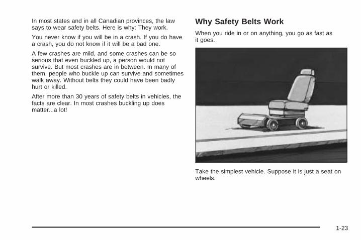
Why Safety Belts WorkWhen you ride in or on anything, you go as fast asit goes.
Take the simplest vehicle. Suppose it is just a seat onwheels.
1-23
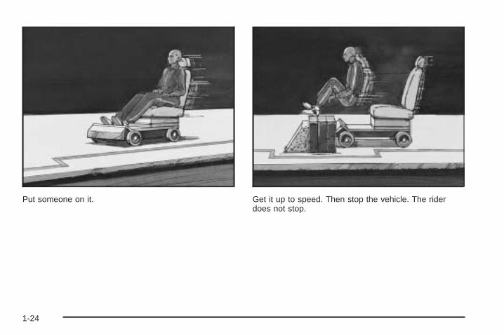
Put someone on it. Get it up to speed. Then stop the vehicle. The riderdoes not stop.
1-24
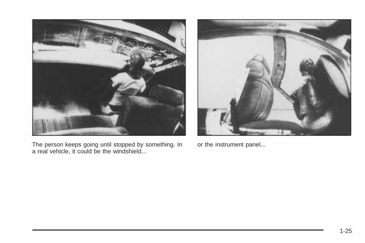
The person keeps going until stopped by something. Ina real vehicle, it could be the windshield...
or the instrument panel...
1-25
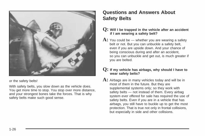
or the safety belts!
With safety belts, you slow down as the vehicle does.You get more time to stop. You stop over more distance,and your strongest bones take the forces. That is whysafety belts make such good sense.
Questions and Answers AboutSafety Belts
Q: Will I be trapped in the vehicle after an accidentif I am wearing a safety belt?
A: You could be — whether you are wearing a safetybelt or not. But you can unbuckle a safety belt,even if you are upside down. And your chance ofbeing conscious during and after an accident,so you can unbuckle and get out, is much greater ifyou are belted.
Q: If my vehicle has airbags, why should I have towear safety belts?
A: Airbags are in many vehicles today and will be inmost of them in the future. But they aresupplemental systems only; so they work withsafety belts — not instead of them. Every airbagsystem ever offered for sale has required the use ofsafety belts. Even if you are in a vehicle that hasairbags, you still have to buckle up to get the mostprotection. That is true not only in frontal collisions,but especially in side and other collisions.
1-26
Q: If I am a good driver, and I never drive far fromhome, why should I wear safety belts?
A: You may be an excellent driver, but if you are in anaccident — even one that is not your fault — youand your passengers can be hurt. Being a gooddriver does not protect you from things beyond yourcontrol, such as bad drivers.
Most accidents occur within 25 miles (40 km) ofhome. And the greatest number of serious injuriesand deaths occur at speeds of less than 40 mph(65 km/h).
Safety belts are for everyone.
How to Wear Safety Belts ProperlyThis part is only for people of adult size.
Be aware that there are special things to know aboutsafety belts and children. And there are differentrules for smaller children and babies. If a child will beriding in your vehicle, see Older Children on page 1-42or Infants and Young Children on page 1-45. Followthose rules for everyone’s protection.
First, you will want to know which restraint systems yourvehicle has.
We will start with the driver position.
Driver Position
Lap-Shoulder BeltThe driver has a lap-shoulder belt. Here is how to wearit properly.
1. Close and lock the door.
2. Adjust the seat so you can sit up straight. To seehow, see “Seats” in the Index.
1-27
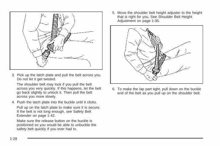
3. Pick up the latch plate and pull the belt across you.Do not let it get twisted.The shoulder belt may lock if you pull the beltacross you very quickly. If this happens, let the beltgo back slightly to unlock it. Then pull the beltacross you more slowly.
4. Push the latch plate into the buckle until it clicks.Pull up on the latch plate to make sure it is secure.If the belt is not long enough, see Safety BeltExtender on page 1-42.Make sure the release button on the buckle ispositioned so you would be able to unbuckle thesafety belt quickly if you ever had to.
5. Move the shoulder belt height adjuster to the heightthat is right for you. See Shoulder Belt HeightAdjustment on page 1-35.
6. To make the lap part tight, pull down on the buckleend of the belt as you pull up on the shoulder belt.
1-28
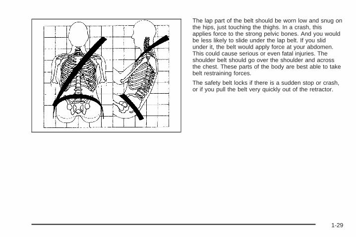
The lap part of the belt should be worn low and snug onthe hips, just touching the thighs. In a crash, thisapplies force to the strong pelvic bones. And you wouldbe less likely to slide under the lap belt. If you slidunder it, the belt would apply force at your abdomen.This could cause serious or even fatal injuries. Theshoulder belt should go over the shoulder and acrossthe chest. These parts of the body are best able to takebelt restraining forces.
The safety belt locks if there is a sudden stop or crash,or if you pull the belt very quickly out of the retractor.
1-29
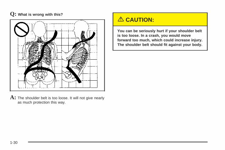
Q: What is wrong with this?
A: The shoulder belt is too loose. It will not give nearlyas much protection this way.
{CAUTION:
You can be seriously hurt if your shoulder beltis too loose. In a crash, you would moveforward too much, which could increase injury.The shoulder belt should fit against your body.
1-30
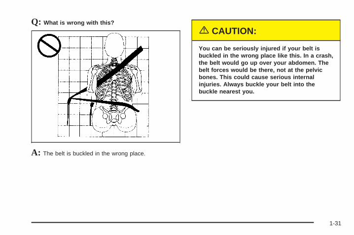
Q: What is wrong with this?
A: The belt is buckled in the wrong place.
{CAUTION:
You can be seriously injured if your belt isbuckled in the wrong place like this. In a crash,the belt would go up over your abdomen. Thebelt forces would be there, not at the pelvicbones. This could cause serious internalinjuries. Always buckle your belt into thebuckle nearest you.
1-31
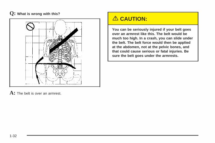
Q: What is wrong with this?
A: The belt is over an armrest.
{CAUTION:
You can be seriously injured if your belt goesover an armrest like this. The belt would bemuch too high. In a crash, you can slide underthe belt. The belt force would then be appliedat the abdomen, not at the pelvic bones, andthat could cause serious or fatal injuries. Besure the belt goes under the armrests.
1-32
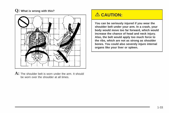
Q: What is wrong with this?
A: The shoulder belt is worn under the arm. It shouldbe worn over the shoulder at all times.
{CAUTION:
You can be seriously injured if you wear theshoulder belt under your arm. In a crash, yourbody would move too far forward, which wouldincrease the chance of head and neck injury.Also, the belt would apply too much force tothe ribs, which are not as strong as shoulderbones. You could also severely injure internalorgans like your liver or spleen.
1-33
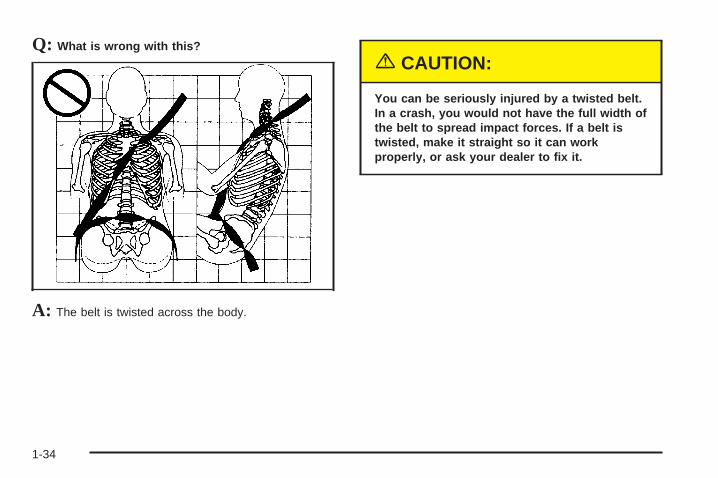
Q: What is wrong with this?
A: The belt is twisted across the body.
{CAUTION:
You can be seriously injured by a twisted belt.In a crash, you would not have the full width ofthe belt to spread impact forces. If a belt istwisted, make it straight so it can workproperly, or ask your dealer to fix it.
1-34
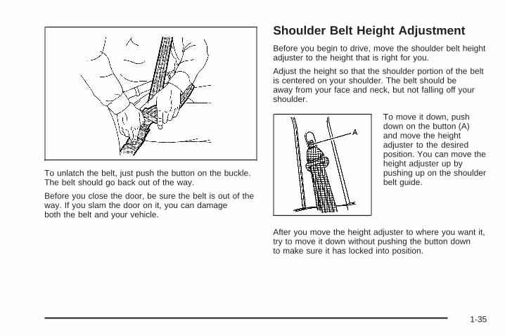
To unlatch the belt, just push the button on the buckle.The belt should go back out of the way.
Before you close the door, be sure the belt is out of theway. If you slam the door on it, you can damageboth the belt and your vehicle.
Shoulder Belt Height AdjustmentBefore you begin to drive, move the shoulder belt heightadjuster to the height that is right for you.
Adjust the height so that the shoulder portion of the beltis centered on your shoulder. The belt should beaway from your face and neck, but not falling off yourshoulder.
To move it down, pushdown on the button (A)and move the heightadjuster to the desiredposition. You can move theheight adjuster up bypushing up on the shoulderbelt guide.
After you move the height adjuster to where you want it,try to move it down without pushing the button downto make sure it has locked into position.
1-35
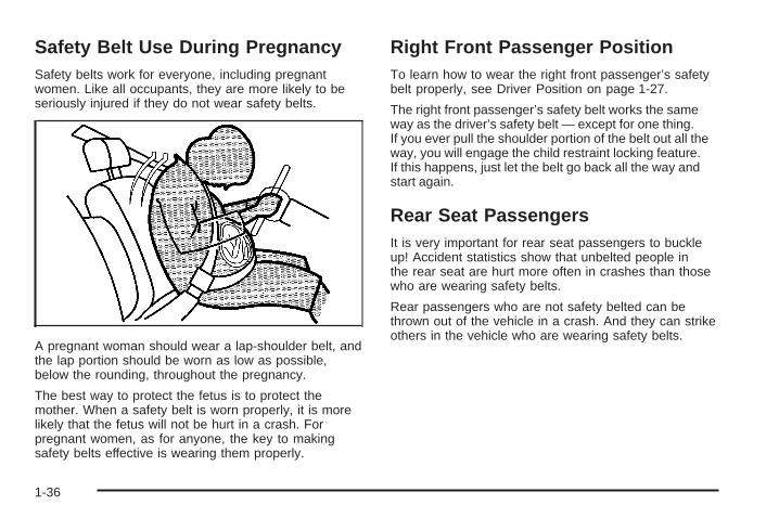
Safety Belt Use During PregnancySafety belts work for everyone, including pregnantwomen. Like all occupants, they are more likely to beseriously injured if they do not wear safety belts.
A pregnant woman should wear a lap-shoulder belt, andthe lap portion should be worn as low as possible,below the rounding, throughout the pregnancy.
The best way to protect the fetus is to protect themother. When a safety belt is worn properly, it is morelikely that the fetus will not be hurt in a crash. Forpregnant women, as for anyone, the key to makingsafety belts effective is wearing them properly.
Right Front Passenger PositionTo learn how to wear the right front passenger’s safetybelt properly, see Driver Position on page 1-27.
The right front passenger’s safety belt works the sameway as the driver’s safety belt — except for one thing.If you ever pull the shoulder portion of the belt out all theway, you will engage the child restraint locking feature.If this happens, just let the belt go back all the way andstart again.
Rear Seat PassengersIt is very important for rear seat passengers to buckleup! Accident statistics show that unbelted people inthe rear seat are hurt more often in crashes than thosewho are wearing safety belts.
Rear passengers who are not safety belted can bethrown out of the vehicle in a crash. And they can strikeothers in the vehicle who are wearing safety belts.
1-36
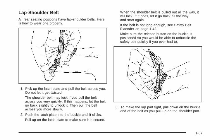
Lap-Shoulder BeltAll rear seating positions have lap-shoulder belts. Hereis how to wear one properly.
1. Pick up the latch plate and pull the belt across you.Do not let it get twisted.The shoulder belt may lock if you pull the beltacross you very quickly. If this happens, let the beltgo back slightly to unlock it. Then pull the beltacross you more slowly.
2. Push the latch plate into the buckle until it clicks.Pull up on the latch plate to make sure it is secure.
When the shoulder belt is pulled out all the way, itwill lock. If it does, let it go back all the wayand start again.If the belt is not long enough, see Safety BeltExtender on page 1-42.Make sure the release button on the buckle ispositioned so you would be able to unbuckle thesafety belt quickly if you ever had to.
3. To make the lap part tight, pull down on the buckleend of the belt as you pull up on the shoulder part.
1-37
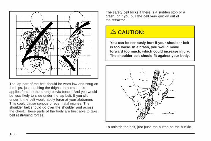
The lap part of the belt should be worn low and snug onthe hips, just touching the thighs. In a crash thisapplies force to the strong pelvic bones. And you wouldbe less likely to slide under the lap belt. If you slidunder it, the belt would apply force at your abdomen.This could cause serious or even fatal injuries. Theshoulder belt should go over the shoulder and acrossthe chest. These parts of the body are best able to takebelt restraining forces.
The safety belt locks if there is a sudden stop or acrash, or if you pull the belt very quickly out ofthe retractor.
{CAUTION:
You can be seriously hurt if your shoulder beltis too loose. In a crash, you would moveforward too much, which could increase injury.The shoulder belt should fit against your body.
To unlatch the belt, just push the button on the buckle.
1-38
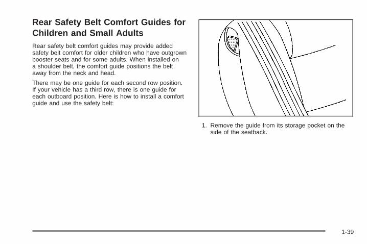
Rear Safety Belt Comfort Guides forChildren and Small AdultsRear safety belt comfort guides may provide addedsafety belt comfort for older children who have outgrownbooster seats and for some adults. When installed ona shoulder belt, the comfort guide positions the beltaway from the neck and head.
There may be one guide for each second row position.If your vehicle has a third row, there is one guide foreach outboard position. Here is how to install a comfortguide and use the safety belt:
1. Remove the guide from its storage pocket on theside of the seatback.
1-39
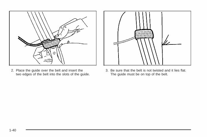
2. Place the guide over the belt and insert thetwo edges of the belt into the slots of the guide.
3. Be sure that the belt is not twisted and it lies flat.The guide must be on top of the belt.
1-40
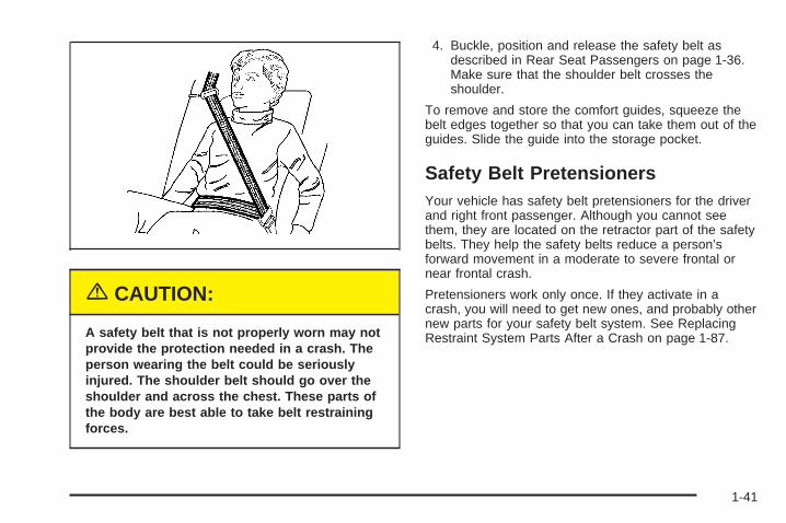
{CAUTION:
A safety belt that is not properly worn may notprovide the protection needed in a crash. Theperson wearing the belt could be seriouslyinjured. The shoulder belt should go over theshoulder and across the chest. These parts ofthe body are best able to take belt restrainingforces.
4. Buckle, position and release the safety belt asdescribed in Rear Seat Passengers on page 1-36.Make sure that the shoulder belt crosses theshoulder.
To remove and store the comfort guides, squeeze thebelt edges together so that you can take them out of theguides. Slide the guide into the storage pocket.
Safety Belt PretensionersYour vehicle has safety belt pretensioners for the driverand right front passenger. Although you cannot seethem, they are located on the retractor part of the safetybelts. They help the safety belts reduce a person’sforward movement in a moderate to severe frontal ornear frontal crash.
Pretensioners work only once. If they activate in acrash, you will need to get new ones, and probably othernew parts for your safety belt system. See ReplacingRestraint System Parts After a Crash on page 1-87.
1-41
Safety Belt ExtenderIf the vehicle’s safety belt will fasten around you, youshould use it.
But if a safety belt is not long enough, your dealer willorder you an extender. It is free. When you go in toorder it, take the heaviest coat you will wear, sothe extender will be long enough for you. To help avoidpersonal injury, do not let someone else use it, anduse it only for the seat it is made to fit. The extender hasbeen designed for adults. Never use it for securingchild seats. To wear it, just attach it to the regular safetybelt. For more information, see the instruction sheetthat comes with the extender.
Child Restraints
Older Children
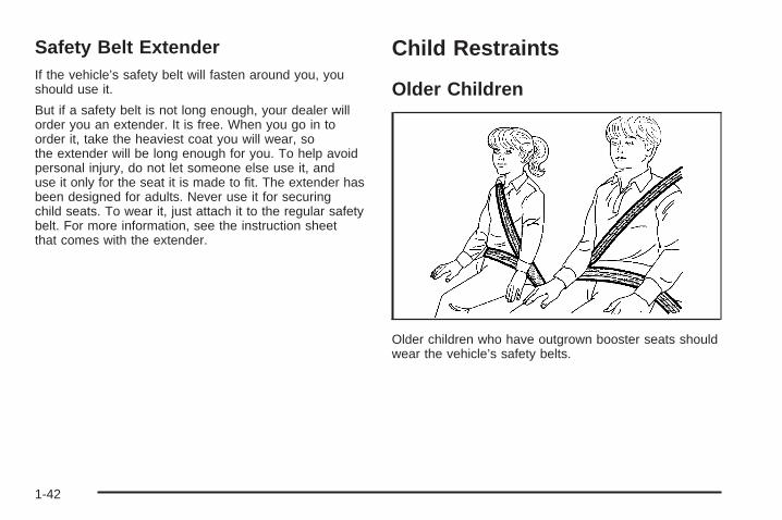
Older children who have outgrown booster seats shouldwear the vehicle’s safety belts.
1-42
Q: What is the proper way to wear safety belts?
A: If possible, an older child should wear alap-shoulder belt and get the additional restraint ashoulder belt can provide. The shoulder beltshould not cross the face or neck. The lap beltshould fit snugly below the hips, just touching thetop of the thighs. It should never be worn overthe abdomen, which could cause severe or evenfatal internal injuries in a crash.
Accident statistics show that children are safer if theyare restrained in the rear seat.
In a crash, children who are not buckled up can strikeother people who are buckled up, or can be thrownout of the vehicle. Older children need to use safetybelts properly.
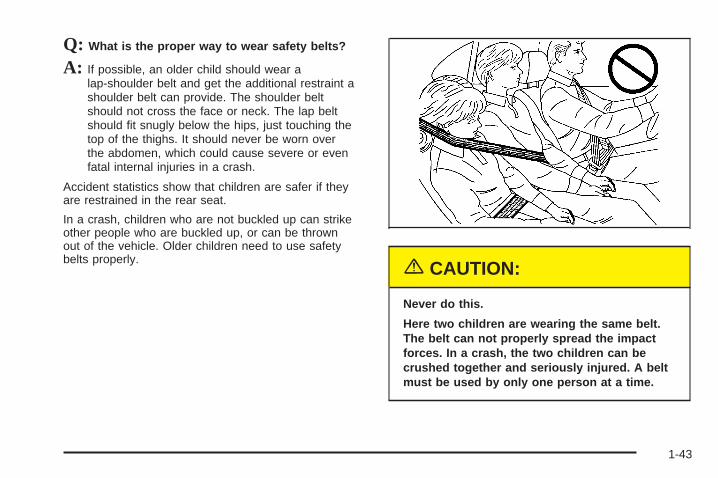
{CAUTION:
Never do this.
Here two children are wearing the same belt.The belt can not properly spread the impactforces. In a crash, the two children can becrushed together and seriously injured. A beltmust be used by only one person at a time.
1-43
Q: What if a child is wearing a lap-shoulder belt,but the child is so small that the shoulder beltis very close to the child’s face or neck?
A: If the child is sitting in a seat next to a window,move the child toward the center of the vehicle.If the child is sitting in a center rear seat position,move the child toward the safety belt buckle. Ineither case, be sure that the shoulder belt still is onthe child’s shoulder, so that in a crash the child’supper body would have the restraint that beltsprovide. If the child is sitting in a second rowposition or a third row outboard position (ifequipped), see Rear Safety Belt Comfort Guides forChildren and Small Adults on page 1-39.
{CAUTION:
Never do this.
Here a child is sitting in a seat that has alap-shoulder belt, but the shoulder part isbehind the child. If the child wears the belt inthis way, in a crash the child might slide underthe belt. The belt’s force would then be appliedright on the child’s abdomen. That could causeserious or fatal injuries.
1-44
Wherever the child sits, the lap portion of the beltshould be worn low and snug on the hips, just touchingthe child’s thighs. This applies belt force to the child’spelvic bones in a crash.
Infants and Young ChildrenEveryone in a vehicle needs protection! This includesinfants and all other children. Neither the distancetraveled nor the age and size of the traveler changesthe need, for everyone, to use safety restraints. In fact,the law in every state in the United States and inevery Canadian province says children up to some agemust be restrained while in a vehicle.
Every time infants and young children ride in vehicles,they should have the protection provided by appropriaterestraints. Young children should not use the vehicle’sadult safety belts alone, unless there is no other choice.Instead, they need to use a child restraint.
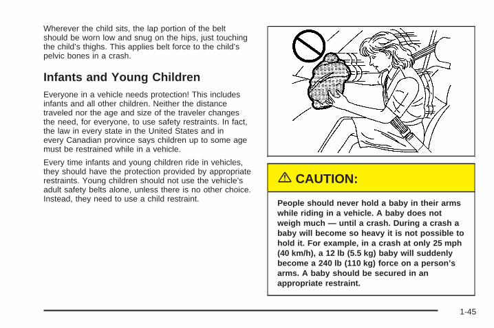
{CAUTION:
People should never hold a baby in their armswhile riding in a vehicle. A baby does notweigh much — until a crash. During a crash ababy will become so heavy it is not possible tohold it. For example, in a crash at only 25 mph(40 km/h), a 12 lb (5.5 kg) baby will suddenlybecome a 240 lb (110 kg) force on a person’sarms. A baby should be secured in anappropriate restraint.
1-45
{CAUTION:
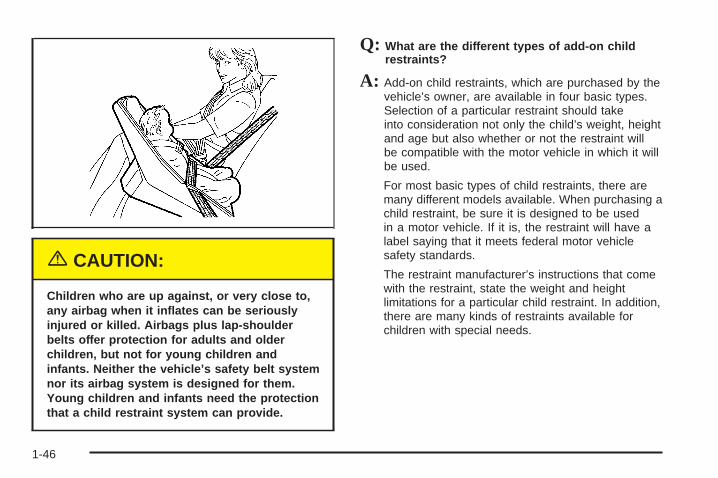
Children who are up against, or very close to,any airbag when it inflates can be seriouslyinjured or killed. Airbags plus lap-shoulderbelts offer protection for adults and olderchildren, but not for young children andinfants. Neither the vehicle’s safety belt systemnor its airbag system is designed for them.Young children and infants need the protectionthat a child restraint system can provide.
Q: What are the different types of add-on childrestraints?
A: Add-on child restraints, which are purchased by thevehicle’s owner, are available in four basic types.Selection of a particular restraint should takeinto consideration not only the child’s weight, heightand age but also whether or not the restraint willbe compatible with the motor vehicle in which it willbe used.
For most basic types of child restraints, there aremany different models available. When purchasing achild restraint, be sure it is designed to be usedin a motor vehicle. If it is, the restraint will have alabel saying that it meets federal motor vehiclesafety standards.
The restraint manufacturer’s instructions that comewith the restraint, state the weight and heightlimitations for a particular child restraint. In addition,there are many kinds of restraints available forchildren with special needs.
1-46
{CAUTION:
Newborn infants need complete support,including support for the head and neck. Thisis necessary because a newborn infant’s neckis weak and its head weighs so muchcompared with the rest of its body. In a crash,an infant in a rear-facing seat settles into therestraint, so the crash forces can bedistributed across the strongest part of aninfant’s body, the back and shoulders. Infantsalways should be secured in appropriate infantrestraints.
{CAUTION:
The body structure of a young child is quiteunlike that of an adult or older child, for whomthe safety belts are designed. A young child’ship bones are still so small that the vehicle’sregular safety belt may not remain low on thehip bones, as it should. Instead, it may settleup around the child’s abdomen. In a crash, thebelt would apply force on a body area that isunprotected by any bony structure. This alonecould cause serious or fatal injuries. Youngchildren always should be secured inappropriate child restraints.
1-47
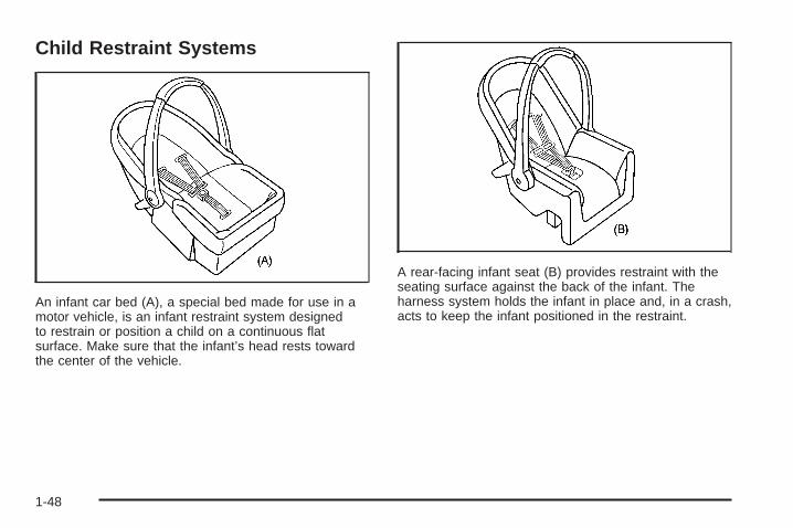
Child Restraint Systems
An infant car bed (A), a special bed made for use in amotor vehicle, is an infant restraint system designedto restrain or position a child on a continuous flatsurface. Make sure that the infant’s head rests towardthe center of the vehicle.
A rear-facing infant seat (B) provides restraint with theseating surface against the back of the infant. Theharness system holds the infant in place and, in a crash,acts to keep the infant positioned in the restraint.
1-48
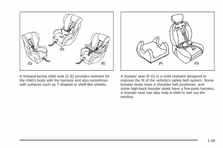
A forward-facing child seat (C-E) provides restraint forthe child’s body with the harness and also sometimeswith surfaces such as T-shaped or shelf-like shields.
A booster seat (F-G) is a child restraint designed toimprove the fit of the vehicle’s safety belt system. Somebooster seats have a shoulder belt positioner, andsome high-back booster seats have a five-point harness.A booster seat can also help a child to see out thewindow.
1-49
Q: How do child restraints work?
A: A child restraint system is any device designed foruse in a motor vehicle to restrain, seat, or positionchildren. A built-in child restraint system is apermanent part of the motor vehicle. An add-onchild restraint system is a portable one, whichis purchased by the vehicle’s owner.For many years, add-on child restraints have usedthe adult belt system in the vehicle. To helpreduce the chance of injury, the child also has to besecured within the restraint. The vehicle’s beltsystem secures the add-on child restraint in thevehicle, and the add-on child restraint’s harnesssystem holds the child in place within the restraint.One system, the three-point harness, has straps thatcome down over each of the infant’s shoulders andbuckle together at the crotch. The five-point harnesssystem has two shoulder straps, two hip straps and acrotch strap. A shield may take the place of hipstraps. A T-shaped shield has shoulder straps thatare attached to a flat pad which rests low against thechild’s body. A shelf- or armrest-type shield hasstraps that are attached to a wide, shelf-like shieldthat swings up or to the side.When choosing a child restraint, be sure the childrestraint is designed to be used in a vehicle. If it is,it will have a label saying that it meets federalmotor vehicle safety standards.
Then follow the instructions for the restraint. Youmay find these instructions on the restraint itself or ina booklet, or both. These restraints use the beltsystem or the LATCH system in your vehicle, but thechild also has to be secured within the restraint tohelp reduce the chance of personal injury. Whensecuring an add-on child restraint, refer to theinstructions that come with the restraint which maybe on the restraint itself or in a booklet, or both, andto this manual. The child restraint instructions areimportant, so if they are not available, obtain areplacement copy from the manufacturer.
Keep in mind that an unsecured child restraintcan move around in a collision or sudden stopand injure people in the vehicle. Be sure to properlysecure any child restraint in your vehicle – evenwhen no child is in it.
Q: When securing an aftermarket child seat in abucket seat, I am unable to get the seatfastened in snugly enough. What should I do?
A: With some child seats, it may be difficult to tightenthe vehicle belts so that there is less side-to-side orfront-to-back movement of the child seat. Areplacement buckle, which makes it easier tosecure your child seat, is available from your dealerat no charge to you.
1-50
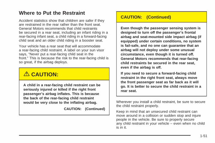
Where to Put the RestraintAccident statistics show that children are safer if theyare restrained in the rear rather than the front seat.General Motors recommends that child restraintsbe secured in a rear seat, including an infant riding in arear-facing infant seat, a child riding in a forward-facingchild seat and an older child riding in a booster seat.
Your vehicle has a rear seat that will accommodatea rear-facing child restraint. A label on your sun visorsays, “Never put a rear-facing child seat in thefront.” This is because the risk to the rear-facing child isso great, if the airbag deploys.
{CAUTION:
A child in a rear-facing child restraint can beseriously injured or killed if the right frontpassenger’s airbag inflates. This is becausethe back of the rear-facing child restraintwould be very close to the inflating airbag.
CAUTION: (Continued)
CAUTION: (Continued)
Even though the passenger sensing system isdesigned to turn off the passenger’s frontalairbag and seat-mounted side impact airbag (ifequipped) under certain conditions, no systemis fail-safe, and no one can guarantee that anairbag will not deploy under some unusualcircumstance, even though it is turned off.General Motors recommends that rear-facingchild restraints be secured in the rear seat,even if the airbag is off.
If you need to secure a forward-facing childrestraint in the right front seat, always movethe front passenger seat as far back as it willgo. It is better to secure the child restraint in arear seat.
Wherever you install a child restraint, be sure to securethe child restraint properly.
Keep in mind that an unsecured child restraint canmove around in a collision or sudden stop and injurepeople in the vehicle. Be sure to properly secureany child restraint in your vehicle – even when no childis in it.
1-51
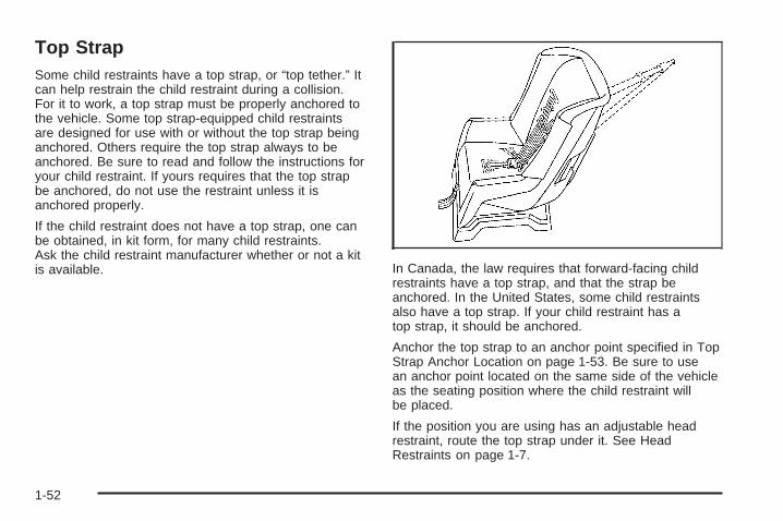
Top StrapSome child restraints have a top strap, or “top tether.” Itcan help restrain the child restraint during a collision.For it to work, a top strap must be properly anchored tothe vehicle. Some top strap-equipped child restraintsare designed for use with or without the top strap beinganchored. Others require the top strap always to beanchored. Be sure to read and follow the instructions foryour child restraint. If yours requires that the top strapbe anchored, do not use the restraint unless it isanchored properly.
If the child restraint does not have a top strap, one canbe obtained, in kit form, for many child restraints.Ask the child restraint manufacturer whether or not a kitis available. In Canada, the law requires that forward-facing child
restraints have a top strap, and that the strap beanchored. In the United States, some child restraintsalso have a top strap. If your child restraint has atop strap, it should be anchored.
Anchor the top strap to an anchor point specified in TopStrap Anchor Location on page 1-53. Be sure to usean anchor point located on the same side of the vehicleas the seating position where the child restraint willbe placed.
If the position you are using has an adjustable headrestraint, route the top strap under it. See HeadRestraints on page 1-7.
1-52
{CAUTION:
Each top tether bracket is designed to anchoronly one child restraint. Attaching more thanone child restraint to a single bracket couldcause the anchor to come loose or even breakduring a crash. A child or others could beinjured if this happens. To help prevent injuryto people and damage to your vehicle, attachonly one child restraint per bracket.
Once you have the top strap anchored, you will beready to secure the child restraint itself. Tighten the topstrap when and as the child restraint manufacturer’sinstructions say.
Top Strap Anchor LocationDo not secure a child restraint in the right frontpassenger’s position or at the third row passenger’s-sideposition if a national or local law requires that the topstrap be anchored, or if the instructions that comewith the child restraint say that the top strap must beanchored. There is no place to anchor the top strap inthese positions.
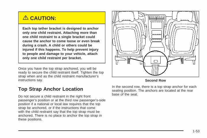
In the second row, there is a top strap anchor for eachseating position. The anchors are located at the rearbase of the seat.
Second Row
1-53
A. Top Strap AnchorB. Seatback Release Latch
In the third row (if equipped), there is a top strap anchorfor the driver’s-side position or for the center position.The anchor is located on the back of the seat nearthe center of the seatback. The anchor canaccommodate one top strap.
Lower Anchorages and Top Tethersfor Children (LATCH System)Your vehicle has the LATCH system. There are anchorsin each seating position in the second row.
This system, designed to make installation of childrestraints easier, does not use the vehicle’s safety belts.Instead, it uses vehicle anchors and child restraintattachments to secure the restraints. Some restraintsalso use another vehicle anchor to secure a toptether strap.
A. Lower AnchorageB. Lower Anchorage
C. Top Tether
Third Row
1-54
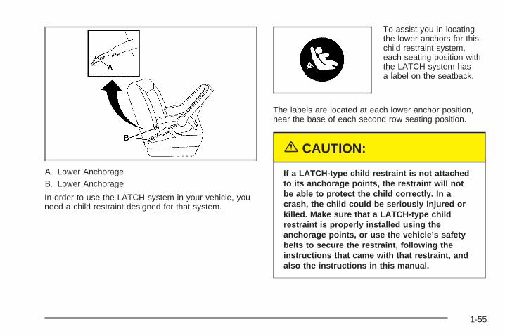
A. Lower AnchorageB. Lower Anchorage
In order to use the LATCH system in your vehicle, youneed a child restraint designed for that system.
To assist you in locatingthe lower anchors for thischild restraint system,each seating position withthe LATCH system hasa label on the seatback.
The labels are located at each lower anchor position,near the base of each second row seating position.
{CAUTION:
If a LATCH-type child restraint is not attachedto its anchorage points, the restraint will notbe able to protect the child correctly. In acrash, the child could be seriously injured orkilled. Make sure that a LATCH-type childrestraint is properly installed using theanchorage points, or use the vehicle’s safetybelts to secure the restraint, following theinstructions that came with that restraint, andalso the instructions in this manual.
1-55
Securing a Child Restraint Designedfor the LATCH System
1. Find the LATCH anchorages for the seatingposition you want to use, where the bottom of theseatback meets the back of the seat cushion.See Lower Anchorages and Top Tethers forChildren (LATCH System) on page 1-54.
2. Put the child restraint on the seat.
3. Attach and tighten the LATCH attachments on thechild restraint to the LATCH anchorages in thevehicle. The child restraint instructions will showyou how.
4. If the child restraint is forward-facing, attach andtighten the top tether to the top tether anchorage.The child restraint instructions will show youhow. Also see Top Strap on page 1-52.
5. Push and pull the child restraint in differentdirections to be sure it is secure.
To remove the child restraint, simply unhook the toptether from the top tether anchorage and thendisconnect the LATCH attachments from the LATCHanchorages.
Securing a Child Restraint in a RearSeat PositionIf your child restraint is equipped with the LATCHsystem, see Lower Anchorages and Top Tethers forChildren (LATCH System) on page 1-54. See Top Strapon page 1-52 if the child restraint has a top strap ortop tether.
For vehicles with a third row, there is no top strapanchor in the passenger’s-side position. Do not securea child seat in this position if a national or local lawrequires that the top strap be anchored, or if theinstructions that come with the child restraint say thatthe top strap must be anchored.
If your child restraint does not have the LATCH system,you will be using the lap-shoulder belt to secure thechild restraint. Be sure to follow the instructionsthat came with the child restraint. Secure the child in thechild restraint when and as the instructions say.
1. Put the child restraint on the seat.
2. Pick up the latch plate, and run the lap and shoulderportions of the vehicle’s safety belt through oraround the restraint. The child restraint instructionswill show you how.
1-56
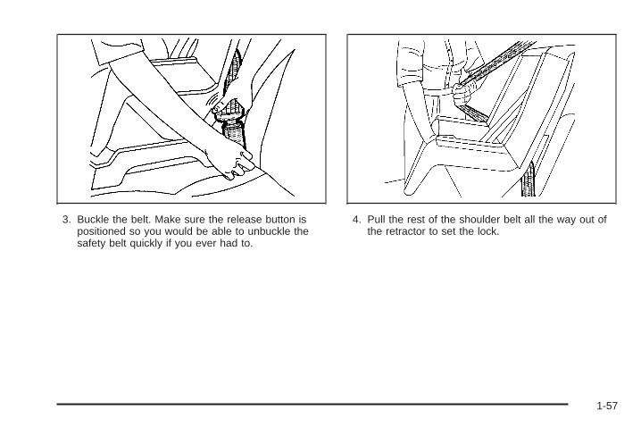
3. Buckle the belt. Make sure the release button ispositioned so you would be able to unbuckle thesafety belt quickly if you ever had to.
4. Pull the rest of the shoulder belt all the way out ofthe retractor to set the lock.
1-57
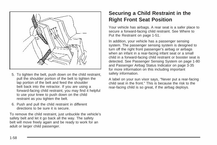
5. To tighten the belt, push down on the child restraint,pull the shoulder portion of the belt to tighten thelap portion of the belt and feed the shoulderbelt back into the retractor. If you are using aforward-facing child restraint, you may find it helpfulto use your knee to push down on the childrestraint as you tighten the belt.
6. Push and pull the child restraint in differentdirections to be sure it is secure.
To remove the child restraint, just unbuckle the vehicle’ssafety belt and let it go back all the way. The safetybelt will move freely again and be ready to work for anadult or larger child passenger.
Securing a Child Restraint in theRight Front Seat PositionYour vehicle has airbags. A rear seat is a safer place tosecure a forward-facing child restraint. See Where toPut the Restraint on page 1-51.
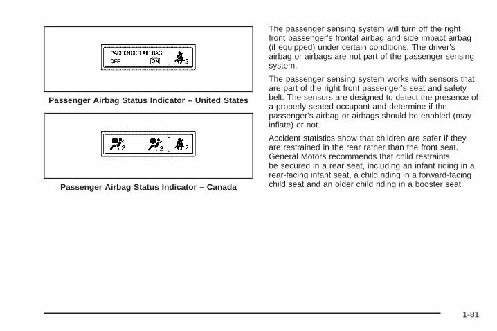
In addition, your vehicle has a passenger sensingsystem. The passenger sensing system is designed toturn off the right front passenger’s airbag or airbagswhen an infant in a rear-facing infant seat or a smallchild in a forward-facing child restraint or booster seat isdetected. See Passenger Sensing System on page 1-80and Passenger Airbag Status Indicator on page 3-35for more information on this including importantsafety information.
A label on your sun visor says, “Never put a rear-facingchild seat in the front.” This is because the risk to therear-facing child is so great, if the airbag deploys.
1-58
{CAUTION:
A child in a rear-facing child restraint can beseriously injured or killed if the right frontpassenger’s airbag inflates. This is becausethe back of the rear-facing child restraintwould be very close to the inflating airbag.
Even though the passenger sensing system isdesigned to turn off the passenger’s frontalairbag and seat-mounted side impact airbag (ifequipped) under certain conditions, no systemis fail-safe, and no one can guarantee that anairbag will not deploy under some unusualcircumstance, even though it is turned off.General Motors recommends that rear-facingchild restraints be secured in the rear seat,even if the airbag is off.
If you need to secure a forward-facing child restraint inthe right front seat position, move the seat as farback as it will go before securing the forward-facingchild restraint. See Manual Seats on page 1-3 orSix-Way Power Seats on page 1-4.
If your child restraint is equipped with the LATCHsystem, see Lower Anchorages and Top Tethers forChildren (LATCH System) on page 1-54.There is no top strap anchor at the right front seatingposition. Do not secure a child seat in this position if anational or local law requires that the top strap beanchored or if the instructions that come with the childrestraint say that the top strap must be anchored. SeeTop Strap on page 1-52 if your child restraint has one.
You will be using the lap-shoulder belt to secure thechild restraint in this position. Be sure to followthe instructions that came with the child restraint.Secure the child in the child restraint when and as theinstructions say.
1. Your vehicle has a right front passenger’s airbags.See Passenger Sensing System on page 1-80.General Motors recommends that rear-facing childrestraints be secured in a rear seat, even if theairbag or airbags are off. If your child restraint isforward-facing, move the seat as far back as it willgo before securing the child restraint in thisseat. See Manual Seats on page 1-3 or Six-WayPower Seats on page 1-4.When the passenger sensing system has turned offthe right front passenger’s airbag or airbags, theoff indicator in the passenger airbag status indicatorshould light and stay lit when you turn the ignitionto RUN or START. See Passenger AirbagStatus Indicator on page 3-35.
1-59
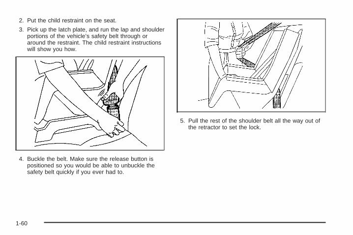
2. Put the child restraint on the seat.
3. Pick up the latch plate, and run the lap and shoulderportions of the vehicle’s safety belt through oraround the restraint. The child restraint instructionswill show you how.
4. Buckle the belt. Make sure the release button ispositioned so you would be able to unbuckle thesafety belt quickly if you ever had to.
5. Pull the rest of the shoulder belt all the way out ofthe retractor to set the lock.
1-60
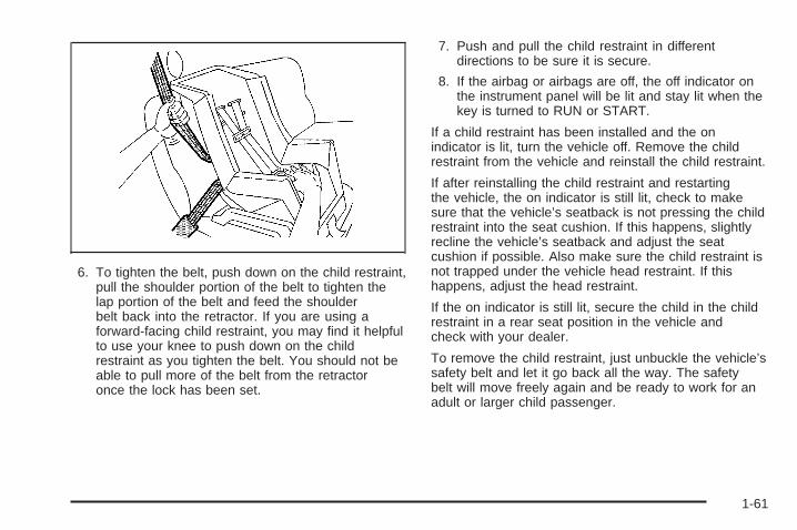
6. To tighten the belt, push down on the child restraint,pull the shoulder portion of the belt to tighten thelap portion of the belt and feed the shoulderbelt back into the retractor. If you are using aforward-facing child restraint, you may find it helpfulto use your knee to push down on the childrestraint as you tighten the belt. You should not beable to pull more of the belt from the retractoronce the lock has been set.
7. Push and pull the child restraint in differentdirections to be sure it is secure.
8. If the airbag or airbags are off, the off indicator onthe instrument panel will be lit and stay lit when thekey is turned to RUN or START.
If a child restraint has been installed and the onindicator is lit, turn the vehicle off. Remove the childrestraint from the vehicle and reinstall the child restraint.
If after reinstalling the child restraint and restartingthe vehicle, the on indicator is still lit, check to makesure that the vehicle’s seatback is not pressing the childrestraint into the seat cushion. If this happens, slightlyrecline the vehicle’s seatback and adjust the seatcushion if possible. Also make sure the child restraint isnot trapped under the vehicle head restraint. If thishappens, adjust the head restraint.
If the on indicator is still lit, secure the child in the childrestraint in a rear seat position in the vehicle andcheck with your dealer.
To remove the child restraint, just unbuckle the vehicle’ssafety belt and let it go back all the way. The safetybelt will move freely again and be ready to work for anadult or larger child passenger.
1-61
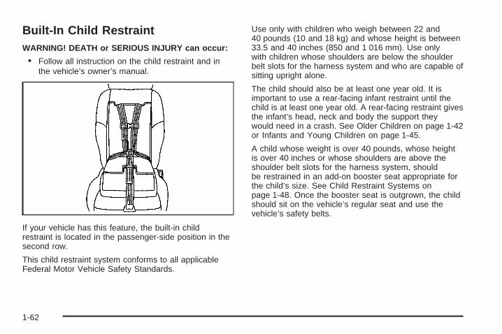
Built-In Child RestraintWARNING! DEATH or SERIOUS INJURY can occur:
• Follow all instruction on the child restraint and inthe vehicle’s owner’s manual.
If your vehicle has this feature, the built-in childrestraint is located in the passenger-side position in thesecond row.
This child restraint system conforms to all applicableFederal Motor Vehicle Safety Standards.
Use only with children who weigh between 22 and40 pounds (10 and 18 kg) and whose height is between33.5 and 40 inches (850 and 1 016 mm). Use onlywith children whose shoulders are below the shoulderbelt slots for the harness system and who are capable ofsitting upright alone.
The child should also be at least one year old. It isimportant to use a rear-facing infant restraint until thechild is at least one year old. A rear-facing restraint givesthe infant’s head, neck and body the support theywould need in a crash. See Older Children on page 1-42or Infants and Young Children on page 1-45.
A child whose weight is over 40 pounds, whose heightis over 40 inches or whose shoulders are above theshoulder belt slots for the harness system, shouldbe restrained in an add-on booster seat appropriate forthe child’s size. See Child Restraint Systems onpage 1-48. Once the booster seat is outgrown, the childshould sit on the vehicle’s regular seat and use thevehicle’s safety belts.
1-62
{CAUTION:
Using the vehicle’s built-in child restraint as abooster seat for a larger child could causeinjury to the child in a sudden stop or crash. Achild whose weight is over 40 pounds, whoseheight is over 40 inches or whose shouldersare above the shoulder belt slots for theharness system should use a restraint systemthat is appropriate for their size, either anadd-on booster seat or the vehicle’s safetybelt. See “Child Restraints” or “OlderChildren” in the Index.
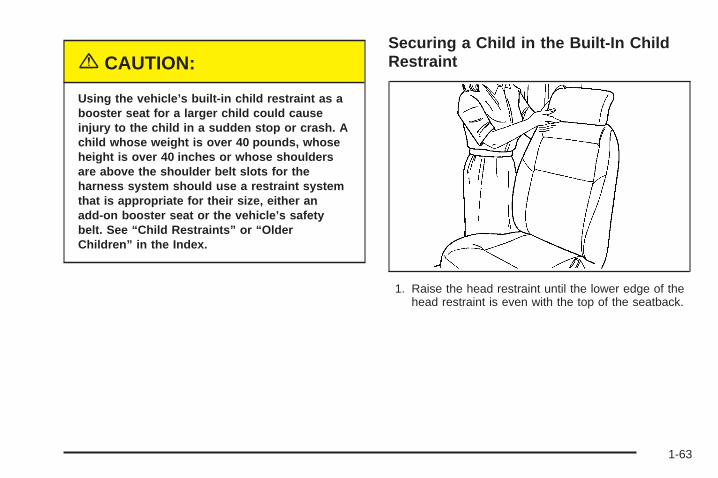
Securing a Child in the Built-In ChildRestraint
1. Raise the head restraint until the lower edge of thehead restraint is even with the top of the seatback.
1-63
2. Rotate the head restraint rearward until it touchesthe top of the seatback. Make sure there is no gapbetween the lower edge of the head restraintand the top of the seatback.
3. Lower the child restraint cushion.
1-64
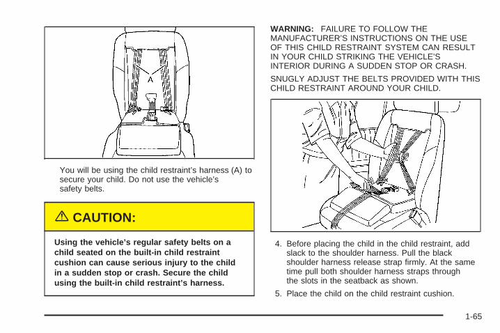
You will be using the child restraint’s harness (A) tosecure your child. Do not use the vehicle’ssafety belts.
{CAUTION:
Using the vehicle’s regular safety belts on achild seated on the built-in child restraintcushion can cause serious injury to the childin a sudden stop or crash. Secure the childusing the built-in child restraint’s harness.
WARNING: FAILURE TO FOLLOW THEMANUFACTURER’S INSTRUCTIONS ON THE USEOF THIS CHILD RESTRAINT SYSTEM CAN RESULTIN YOUR CHILD STRIKING THE VEHICLE’SINTERIOR DURING A SUDDEN STOP OR CRASH.
SNUGLY ADJUST THE BELTS PROVIDED WITH THISCHILD RESTRAINT AROUND YOUR CHILD.
4. Before placing the child in the child restraint, addslack to the shoulder harness. Pull the blackshoulder harness release strap firmly. At the sametime pull both shoulder harness straps throughthe slots in the seatback as shown.
5. Place the child on the child restraint cushion.
1-65
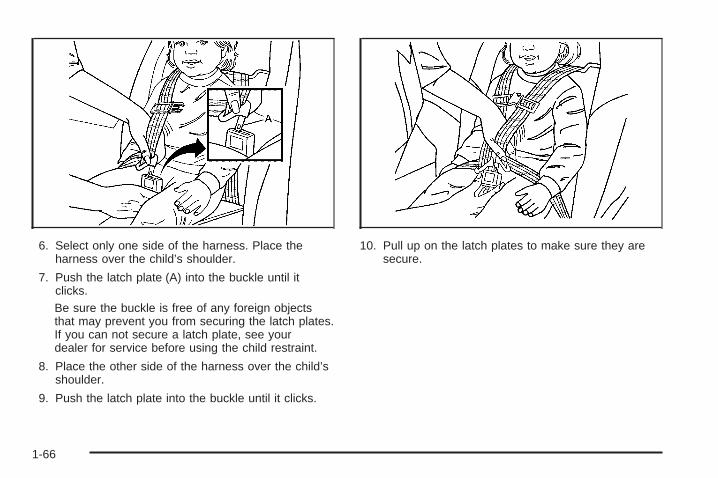
6. Select only one side of the harness. Place theharness over the child’s shoulder.
7. Push the latch plate (A) into the buckle until itclicks.Be sure the buckle is free of any foreign objectsthat may prevent you from securing the latch plates.If you can not secure a latch plate, see yourdealer for service before using the child restraint.
8. Place the other side of the harness over the child’sshoulder.
9. Push the latch plate into the buckle until it clicks.
10. Pull up on the latch plates to make sure they aresecure.
1-66
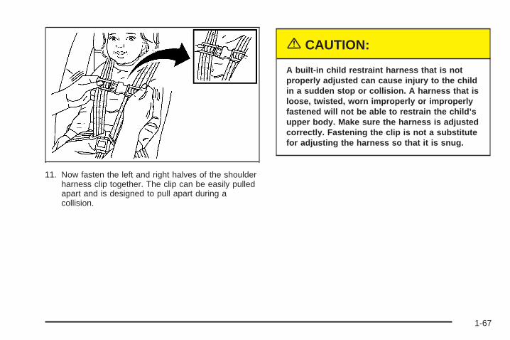
11. Now fasten the left and right halves of the shoulderharness clip together. The clip can be easily pulledapart and is designed to pull apart during acollision.
{CAUTION:
A built-in child restraint harness that is notproperly adjusted can cause injury to the childin a sudden stop or collision. A harness that isloose, twisted, worn improperly or improperlyfastened will not be able to restrain the child’supper body. Make sure the harness is adjustedcorrectly. Fastening the clip is not a substitutefor adjusting the harness so that it is snug.
1-67
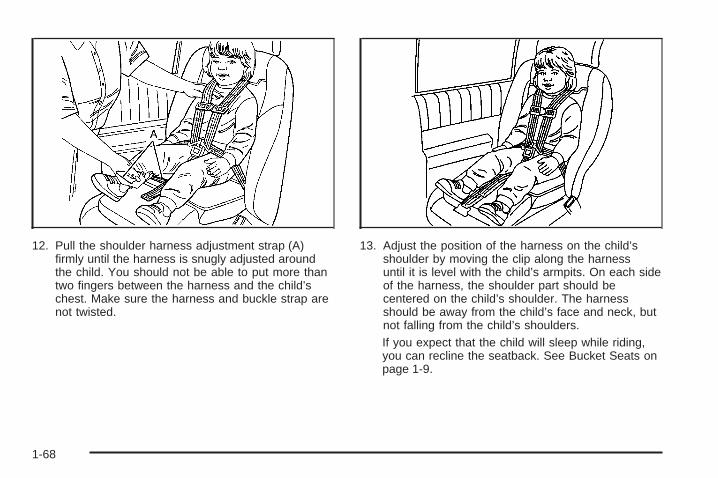
12. Pull the shoulder harness adjustment strap (A)firmly until the harness is snugly adjusted aroundthe child. You should not be able to put more thantwo fingers between the harness and the child’schest. Make sure the harness and buckle strap arenot twisted.
13. Adjust the position of the harness on the child’sshoulder by moving the clip along the harnessuntil it is level with the child’s armpits. On each sideof the harness, the shoulder part should becentered on the child’s shoulder. The harnessshould be away from the child’s face and neck, butnot falling from the child’s shoulders.If you expect that the child will sleep while riding,you can recline the seatback. See Bucket Seats onpage 1-9.
1-68
Removing the Child from the Built-InChild Restraint
1. Unfasten the shoulder harness clip.
2. Unlatch the harness by pushing the button on thebuckle.
3. Move one side of the harness off the child’sshoulder.
4. Move the other side of the harness off the child’sshoulder.
5. Remove the child from the child restraint cushion.
1-69
Storing the Built-In Child RestraintAlways properly store the built-in child restraint beforeusing the vehicle’s lap-shoulder belt.
1. Move both latch plates and both sides of theshoulder harness clip to the bottom of the harnessstraps.
2. Fold the child restraint cushion and leg rest up intothe seatback.
3. Press the child restraint cushion firmly into theseatback.
1-70
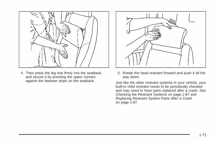
4. Then press the leg rest firmly into the seatback,and secure it by pressing the upper cornersagainst the fastener strips on the seatback.
5. Rotate the head restraint forward and push it all theway down.
Just like the other restraint systems in your vehicle, yourbuilt-in child restraint needs to be periodically checkedand may need to have parts replaced after a crash. SeeChecking the Restraint Systems on page 1-87 andReplacing Restraint System Parts After a Crashon page 1-87.
1-71
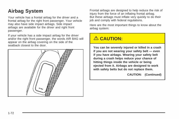
Airbag SystemYour vehicle has a frontal airbag for the driver and afrontal airbag for the right front passenger. Your vehiclemay also have side impact airbags. Side impactairbags are available for the driver and right frontpassenger.
If your vehicle has a side impact airbag for the driverand/or the right front passenger, the words AIR BAG willappear on the airbag covering on the side of theseatback closest to the door.
Frontal airbags are designed to help reduce the risk ofinjury from the force of an inflating frontal airbag.But these airbags must inflate very quickly to do theirjob and comply with federal regulations.
Here are the most important things to know about theairbag system:
{CAUTION:
You can be severely injured or killed in a crashif you are not wearing your safety belt — evenif you have airbags. Wearing your safety beltduring a crash helps reduce your chance ofhitting things inside the vehicle or beingejected from it. Airbags are designed to workwith safety belts but do not replace them.
CAUTION: (Continued)
1-72
CAUTION: (Continued)
Frontal airbags for the driver and right frontpassenger are designed to deploy in moderateto severe frontal and near frontal crashes.They are not designed to inflate in rollover,rear or low-speed frontal crashes, or in manyside crashes. And, for some unrestrainedoccupants, frontal airbags may provide lessprotection in frontal crashes than moreforceful airbags have provided in the past.
Side impact airbags for the driver and rightfront passenger are designed to inflate inmoderate to severe crashes where somethinghits the side of your vehicle. They are notdesigned to inflate in frontal, in rollover or inrear crashes.
Everyone in your vehicle should wear a safetybelt properly — whether or not there is anairbag for that person.
{CAUTION:
Both frontal and side impact airbags inflatewith great force, faster than the blink of aneye. If you are too close to an inflating airbag,as you would be if you were leaning forward, itcould seriously injure you. Safety belts helpkeep you in position for airbag inflation beforeand during a crash. Always wear your safetybelt, even with frontal airbags. The drivershould sit as far back as possible while stillmaintaining control of the vehicle. Frontoccupants should not lean on or sleep againstthe door.
1-73
{CAUTION:
Anyone who is up against, or very close to,any airbag when it inflates can be seriouslyinjured or killed. Airbags plus lap-shoulderbelts offer the best protection for adults, butnot for young children and infants. Neither thevehicle’s safety belt system nor its airbagsystem is designed for them. Young childrenand infants need the protection that a childrestraint system can provide. Always securechildren properly in your vehicle. To read how,see Older Children on page 1-42 or Infants andYoung Children on page 1-45.
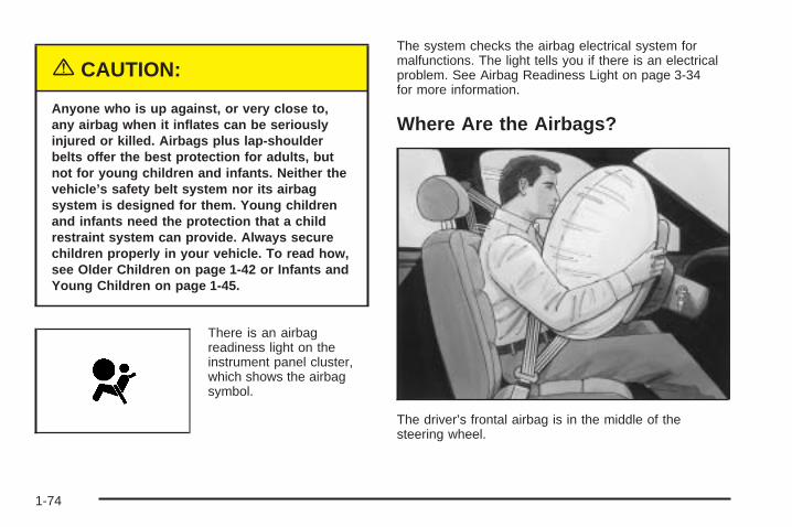
There is an airbagreadiness light on theinstrument panel cluster,which shows the airbagsymbol.
The system checks the airbag electrical system formalfunctions. The light tells you if there is an electricalproblem. See Airbag Readiness Light on page 3-34for more information.
Where Are the Airbags?
The driver’s frontal airbag is in the middle of thesteering wheel.
1-74
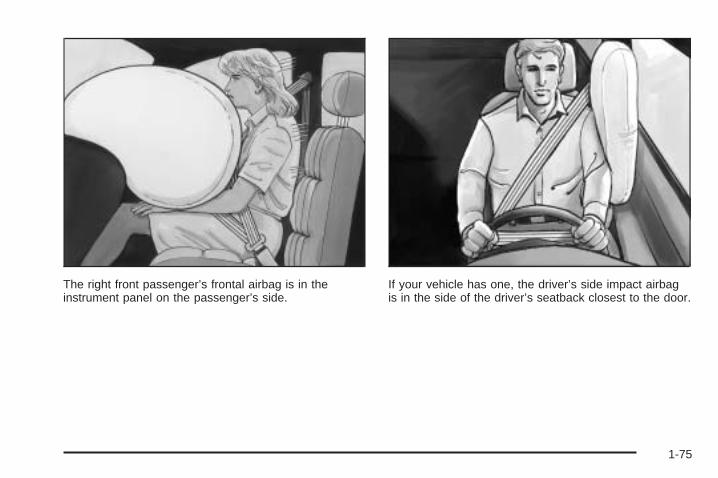
The right front passenger’s frontal airbag is in theinstrument panel on the passenger’s side.
If your vehicle has one, the driver’s side impact airbagis in the side of the driver’s seatback closest to the door.
1-75
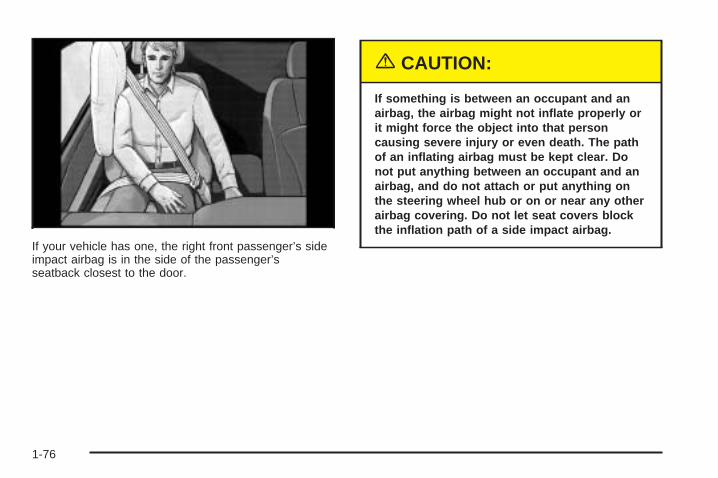
If your vehicle has one, the right front passenger’s sideimpact airbag is in the side of the passenger’sseatback closest to the door.
{CAUTION:
If something is between an occupant and anairbag, the airbag might not inflate properly orit might force the object into that personcausing severe injury or even death. The pathof an inflating airbag must be kept clear. Donot put anything between an occupant and anairbag, and do not attach or put anything onthe steering wheel hub or on or near any otherairbag covering. Do not let seat covers blockthe inflation path of a side impact airbag.
1-76
When Should an Airbag Inflate?The driver’s and right front passenger’s frontal airbagsare designed to inflate in moderate to severe frontalor near-frontal crashes. But they are designed to inflateonly if the impact exceeds a predetermined deploymentthreshold. Deployment thresholds take into accounta variety of desired deployment and non-deploymentevents and are used to predict how severe a crashis likely to be in time for the airbags to inflate and helprestrain the occupants. Whether your frontal airbagswill or should deploy is not based on how fast yourvehicle is traveling. It depends largely on what you hit,the direction of the impact and how quickly yourvehicle slows down.
In addition, your vehicle has “dual stage” frontal airbags,which adjust the restraint according to crash severity.For moderate frontal impacts, these airbags inflate at alevel less than full deployment. Your vehicle isequipped with electronic frontal sensors, which help thesensing system distinguish between a moderatefrontal impact and a more severe frontal impact.
For more severe frontal impacts, full deployment occurs.If the front of your vehicle goes straight into a wallthat does not move or deform, the threshold level forthe reduced deployment is about 12 to 18 mph(19 to 29 km/h), and the threshold level for a fulldeployment is about 18 to 25 mph (29 to 40.2 km/h).(The threshold level can vary, however, with specificvehicle design, so that it can be somewhat aboveor below this range.)
Airbags may inflate at different crash speeds. Forexample:
• If the vehicle hits a stationary object, the airbagcould inflate at a different crash speed than ifthe object were moving.
• If the object deforms, the airbag could inflate at adifferent crash speed than if the object does notdeform.
• If the vehicle hits a narrow object (like a pole) theairbag could inflate at a different crash speedthan if the vehicle hits a wide object (like a wall).
• If the vehicle goes into an object at an angle theairbag could inflate at a different crash speedthan if the vehicle goes straight into the object.
1-77
The frontal airbags (driver and right front passenger) arenot intended to inflate during vehicle rollovers, rearimpacts, or in many side impacts because inflationwould not likely help the occupants.
Your vehicle may or may not have a side impact airbag.See Airbag System on page 1-72. Side impact airbagsare designed to inflate in moderate to severe sidecrashes. A side impact airbag will inflate if the crashseverity is above the system’s designed “thresholdlevel.” The threshold level can vary with specific vehicledesign. Side impact airbags are not designed toinflate in frontal or near-frontal impacts, rollovers or rearimpacts, because inflation would not likely help theoccupant. A side impact airbag will only deploy on theside of the vehicle that is struck.
In any particular crash, no one can say whether anairbag should have inflated simply because of thedamage to a vehicle or because of what the repair costswere. For frontal airbags, inflation is determined bythe angle of the impact and how quickly the vehicleslows down in frontal and near-frontal impacts. For sideimpact airbags, inflation is determined by the locationand severity of the impact.
What Makes an Airbag Inflate?In an impact of sufficient severity, the airbag sensingsystem detects that the vehicle is in a crash. For bothfrontal and side impact airbags, the sensing systemtriggers a release of gas from the inflator, which inflatesthe airbag. The inflator, the airbag and related hardwareare all part of the airbag modules. Frontal airbag modulesare located inside the steering wheel and instrumentpanel. For vehicles with side impact airbags, the airbagmodules are located in the seatback closest to thedriver’s and/or right front passenger’s door.
How Does an Airbag Restrain?In moderate to severe frontal or near frontal collisions,even belted occupants can contact the steering wheel orthe instrument panel. In moderate to severe sidecollisions, even belted occupants can contact the insideof the vehicle. The airbag supplements the protectionprovided by safety belts. Airbags distribute the force ofthe impact more evenly over the occupant’s upper body,stopping the occupant more gradually. But the frontalairbags would not help you in many types of collisions,including rollovers, rear impacts, and many side impacts,primarily because an occupant’s motion is not toward theairbag. Side impact airbags would not help you in manytypes of collisions, including frontal or near frontalcollisions, rollovers, and rear impacts, primarily becausean occupant’s motion is not toward those airbags.
1-78
Airbags should never be regarded as anything more thana supplement to safety belts, and then only in moderateto severe frontal or near-frontal collisions for the driver’sand right front passenger’s frontal airbags, and only inmoderate to severe side collisions for vehicles with adriver’s and right front passenger’s side impact airbag.
What Will You See After an AirbagInflates?After the airbag inflates, it quickly deflates, so quicklythat some people may not even realize the airbaginflated. Some components of the airbag module will behot for a short time. These components include thesteering wheel hub for the driver’s frontal airbag and theinstrument panel for the right front passenger’s frontalairbag. For vehicles with side impact airbags, the side ofthe seatback closest to the driver’s and/or right frontpassenger’s door will be hot. The parts of the bag thatcome into contact with you may be warm, but nottoo hot to touch. There will be some smoke and dustcoming from the vents in the deflated airbags.Airbag inflation does not prevent the driver from seeingor being able to steer the vehicle, nor does it stoppeople from leaving the vehicle.
{CAUTION:
When an airbag inflates, there is dust in theair. This dust could cause breathing problemsfor people with a history of asthma or otherbreathing trouble. To avoid this, everyone inthe vehicle should get out as soon as it is safeto do so. If you have breathing problems butcannot get out of the vehicle after an airbaginflates, then get fresh air by opening awindow or a door. If you experience breathingproblems following an airbag deployment, youshould seek medical attention.
1-79
In many crashes severe enough to inflate an airbag,windshields are broken by vehicle deformation.Additional windshield breakage may also occur from theright front passenger airbag.
• Airbags are designed to inflate only once. After anairbag inflates, you will need some new parts foryour airbag system. If you do not get them,the airbag system will not be there to help protectyou in another crash. A new system will includeairbag modules and possibly other parts. Theservice manual for your vehicle covers the need toreplace other parts.
• Your vehicle is equipped with a crash sensing anddiagnostic module which records information aftera crash. See Vehicle Data Collection and EventData Recorders on page 7-9.
• Let only qualified technicians work on your airbagsystem. Improper service can mean that anairbag system will not work properly. See yourdealer for service.
Notice: If you damage the covering for the driver’sor the right front passenger’s airbag, or the airbagcovering on the driver’s and right front passenger’sseatback, the airbag may not work properly. Youmay have to replace the airbag module in thesteering wheel, both the airbag module and theinstrument panel for the right front passenger’sairbag, or both the airbag module and seatback forthe driver’s and right front passenger’s sideimpact airbag. Do not open or break the airbagcoverings.
Passenger Sensing SystemYour vehicle has a passenger sensing system. Thepassenger airbag status indicator on the instrumentpanel will be visible when you turn your ignition key toRUN or START. The words ON and OFF or the symbolfor on and off, will be visible during the system check.When the system check is complete, either the word ONor the word OFF, or the symbol for on or the symbolfor off will be visible. See Passenger Airbag StatusIndicator on page 3-35.
1-80
The passenger sensing system will turn off the rightfront passenger’s frontal airbag and side impact airbag(if equipped) under certain conditions. The driver’sairbag or airbags are not part of the passenger sensingsystem.
The passenger sensing system works with sensors thatare part of the right front passenger’s seat and safetybelt. The sensors are designed to detect the presence ofa properly-seated occupant and determine if thepassenger’s airbag or airbags should be enabled (mayinflate) or not.
Accident statistics show that children are safer if theyare restrained in the rear rather than the front seat.General Motors recommends that child restraintsbe secured in a rear seat, including an infant riding in arear-facing infant seat, a child riding in a forward-facingchild seat and an older child riding in a booster seat.
Passenger Airbag Status Indicator – United States
Passenger Airbag Status Indicator – Canada
1-81
Your vehicle has a rear seat that will accommodate arear-facing child restraint. A label on your sun visor says,“Never put a rear-facing child seat in the front.” Thisis because the risk to the rear-facing child is so great, ifthe airbag deploys.
{CAUTION:
A child in a rear-facing child restraint can beseriously injured or killed if the right frontpassenger’s airbag inflates. This is becausethe back of the rear-facing child restraintwould be very close to the inflating airbag.
Even though the passenger sensing system isdesigned to turn off the passenger’s frontalairbag and seat-mounted side impact airbag (ifequipped) under certain conditions, no systemis fail-safe, and no one can guarantee that anairbag will not deploy under some unusualcircumstance, even though it is turned off.General Motors recommends that rear-facingchild restraints be secured in the rear seat,even if the airbag is off.
The passenger sensing system is designed to turn offthe right front passenger’s airbag or airbags if:
• the right front passenger seat is unoccupied
• the system determines that an infant is present in arear-facing infant seat
• the system determines that a small child is presentin a forward-facing child restraint
• the system determines that a small child is presentin a booster seat
• a right front passenger takes his/her weight off ofthe seat for a period of time
• the right front passenger seat is occupied by asmaller person, such as a child who has outgrownchild restraints
• or if there is a critical problem with the airbagsystem or the passenger sensing system.
When the passenger sensing system has turned off thepassenger’s airbag or airbags, the off indicator willlight and stay lit to remind you that the airbag or airbagsare off.
1-82
If a child restraint has been installed and the onindicator is lit, turn the vehicle off. Remove the childrestraint from the vehicle and reinstall the child restraintfollowing the child restraint manufacturer’s directionsand refer to Securing a Child Restraint in the Right FrontSeat Position on page 1-58.
If after reinstalling the child restraint and restarting thevehicle, the on indicator is still lit, check to makesure that the vehicle’s seatback is not pressing the childrestraint into the seat cushion. If this happens, slightlyrecline the vehicle’s seatback and adjust the seatcushion if possible. Also make sure the child restraint isnot trapped under the vehicle head restraint. If thishappens, adjust the head restraint.
If the on indicator is still lit, secure the child in the childrestraint in a rear seat position in the vehicle andcheck with your dealer.
The passenger sensing system is designed to enable(may inflate) the right front passenger’s airbag or airbagsanytime the system senses that a person of adult sizeis sitting properly in the right front passenger’s seat.When the passenger sensing system has allowedthe airbag or airbags to be enabled, the on indicator willlight and stay lit to remind you that the airbag orairbags are active.
For some children who have outgrown child restraintsand for very small adults, the passenger sensing systemmay or may not turn off the right front passenger’sairbag or airbags, depending upon the person’s seatingposture and body build. Everyone in your vehiclewho has outgrown child restraints should wear a safetybelt properly — whether or not there is an airbag forthat person.
If a person of adult-size is sitting in the right frontpassenger’s seat, but the off indicator is lit, it could bebecause that person is not sitting properly in the seat. Ifthis happens, turn the vehicle off and ask the personto place the seatback in the fully upright position, then situpright in the seat, centered on the seat cushion, withthe person’s legs comfortably extended. Restart thevehicle and have the person remain in this position forabout two minutes. This will allow the system todetect that person and then enable the passenger’sairbag or airbags.
1-83
{CAUTION:
If the airbag readiness light in the instrumentpanel cluster ever comes on and stays on, itmeans that something may be wrong with theairbag system. If this ever happens, have thevehicle serviced promptly, because anadult-size person sitting in the right frontpassenger’s seat may not have the protectionof the frontal airbag. See Airbag ReadinessLight on page 3-34 for more on this, includingimportant safety information.
Aftermarket equipment, such as seat covers, can affecthow well the passenger sensing system operates.You may want to consider not using seat covers or otheraftermarket equipment if your vehicle has the passengersensing system. See Adding Equipment to YourAirbag-Equipped Vehicle on page 1-86 for moreinformation about modifications that can affect how thesystem operates.
1-84
{CAUTION:
Stowing of articles under the passenger’s seator between the passenger’s seat cushion andseatback may interfere with the properoperation of the passenger sensing system.
Servicing Your Airbag-EquippedVehicleAirbags affect how your vehicle should be serviced.There are parts of the airbag system in several placesaround your vehicle. Your dealer and the service manualhave information about servicing your vehicle and theairbag system. To purchase a service manual, seeService Publications Ordering Information on page 7-11.
{CAUTION:
For up to 10 seconds after the ignition key isturned off and the battery is disconnected, anairbag can still inflate during improper service.You can be injured if you are close to anairbag when it inflates. Avoid yellowconnectors. They are probably part of theairbag system. Be sure to follow properservice procedures, and make sure the personperforming work for you is qualified to do so.
The airbag system does not need regular maintenance.
1-85
Adding Equipment to YourAirbag-Equipped Vehicle
Q: Is there anything I might add to the front orsides of the vehicle that could keep theairbags from working properly?
A: Yes. If you add things that change your vehicle’sframe, bumper system, front end or side sheetmetal or height, they may keep the airbag systemfrom working properly. Also, the airbag system maynot work properly if you relocate any of the airbagsensors. If you have any questions about this,you should contact Customer Assistance before youmodify your vehicle. The phone numbers andaddresses for Customer Assistance are in Step Twoof the Customer Satisfaction Procedure in thismanual. See Customer Satisfaction Procedure onpage 7-2
Q: Because I have a disability, I have to get myvehicle modified. How can I find out whetherthis will affect my airbag system?
A: Changing or moving any parts of the front seats,safety belts, the airbag sensing and diagnosticmodule (located under the driver’s seat), orthe instrument panel can affect the operation of theairbag system. If you have questions, callCustomer Assistance. The phone numbers andaddresses for Customer Assistance are in Step Twoof the Customer Satisfaction Procedure in thismanual. See Customer Satisfaction Procedure onpage 7-2.
1-86
Restraint System Check
Checking the Restraint SystemsNow and then, make sure the safety belt reminder lightand all your belts, buckles, latch plates, retractorsand anchorages are working properly. If your vehiclehas a built-in child restraint, also periodically make surethe harness straps, latch plates, buckle, clip, childhead restraint and anchorages are working properly.Look for any other loose or damaged safety belt systemparts. If you see anything that might keep a safetybelt system from doing its job, have it repaired.
Torn or frayed safety belts may not protect you in acrash. They can rip apart under impact forces. If a beltis torn or frayed, get a new one right away.
If your vehicle has the built-in child restraint, torn orfrayed harness straps can rip apart under impact forcesjust like torn or frayed safety belts can. They may notprotect a child in a crash. If a harness strap is tornor frayed, get a new harness right away.
Also look for any opened or broken airbag covers, andhave them repaired or replaced. (The airbag systemdoes not need regular maintenance.)
Replacing Restraint System PartsAfter a Crash
{CAUTION:
A crash can damage the restraint systems inyour vehicle. A damaged restraint system maynot properly protect the person using it,resulting in serious injury or even death in acrash. To help make sure your restraintsystems are working properly after a crash,have them inspected and any necessaryreplacements made as soon as possible.
If you have had a crash, do you need new safety belts orbuilt-in child restraint parts or LATCH system parts?
After a very minor collision, nothing may be necessary.But if the safety belts or built-in child restraint harnessstraps were stretched, as they would be if worn during amore severe crash, then you need new parts.
1-87
If the LATCH system was being used during a moresevere crash, then you may need new LATCHsystem parts.
If safety belts or built-in child restraint harness strapsare cut or damaged, replace them. Collision damagealso may mean you will need to have safety belt, built-inchild restraint, LATCH system or seat parts repairedor replaced. New parts and repairs may be necessaryeven if the safety belt, built-in child restraint orLATCH system was not being used at the time of thecollision.
If an airbag inflates, you will need to replace airbagsystem parts. See the part on the airbag system earlierin this section.
If the frontal airbags inflate, you will also need toreplace the driver’s and right front passenger’s safetybelt retractor assemblies. Be sure to do so. Thenthe new retractor assemblies will be there to help protectyou in a collision.
After a crash you may need to replace the driver andfront passenger’s safety belt retractor assemblies, evenif the frontal airbags have not deployed. The driverand front passenger’s safety belt retractor assembliescontain the safety belt pretensioners. Have yoursafety belt pretensioners checked if your vehicle hasbeen in a collision, or if your airbag readiness light stayson after you start your vehicle or while you are driving.See Airbag Readiness Light on page 3-34.
1-88
Keys ...............................................................2-3Remote Keyless Entry System .........................2-4Remote Keyless Entry System Operation ...........2-5
Doors and Locks ............................................2-11Door Locks ..................................................2-11Power Door Locks ........................................2-12Delayed Locking ...........................................2-13Automatic Door Locks ...................................2-13Programmable Automatic Door Unlock .............2-14Lockout Protection ........................................2-14Dual Sliding Doors ........................................2-14Power Sliding Door (PSD) ..............................2-17Liftgate ........................................................2-23
Windows ........................................................2-24Power Windows ............................................2-25Manual Rear Quarter Windows .......................2-26Power Rear Quarter Windows ........................2-26Sun Visors ...................................................2-27
Theft-Deterrent Systems ..................................2-27Content Theft-Deterrent .................................2-27PASS-Key® III ..............................................2-29PASS-Key® III Operation ...............................2-30
Starting and Operating Your Vehicle ................2-31New Vehicle Break-In ....................................2-31Ignition Positions ..........................................2-32Retained Accessory Power (RAP) ...................2-32Starting the Engine .......................................2-33Engine Coolant Heater ..................................2-34Automatic Transaxle Operation .......................2-35All-Wheel Drive ............................................2-38Parking Brake ..............................................2-38Shifting Into Park (P) .....................................2-39Shifting Out of Park (P) .................................2-40Parking Over Things That Burn .......................2-41Engine Exhaust ............................................2-41Running the Engine While Parked ...................2-42
Folding Tray ................................................2-53Second Row Center Console ..........................2-53Luggage Carrier ...........................................2-54Convenience Net
(With Rear Convenience Center) .................2-55Convenience Net
(Without Rear Convenience Center) .............2-56Convenience Center ......................................2-56
Section 2 Features and Controls
2-2
Keys
{CAUTION:
Leaving children in a vehicle with the ignitionkey is dangerous for many reasons. Theycould operate the power windows or othercontrols or even make the vehicle move. Thechildren or others could be badly injured oreven killed. Do not leave the keys in a vehiclewith children.
This vehicle has a double sided key for the ignition andthe driver’s door lock.
2-3
Your vehicle has the PASS-Key® III vehicle theftsystem. The key has a transponder in the key head thatmatches a decoder in the vehicle’s steering column.If a replacement key or any additional key is needed,you must purchase this key from your dealer. Thekey will have PK3 stamped on it. Keep the bar code tagthat came with the original keys. Give this tag to yourdealer if you need a new key made.
Any new PASS-Key® III key must be programmedbefore it will start your vehicle. See PASS-Key® III onpage 2-29 for more information on programmingyour new key.
Notice: If you ever lock your keys in your vehicle,you may have to damage the vehicle to get in.Be sure you have spare keys.
If you ever do get locked out of your vehicle, seeRoadside Assistance Program on page 7-6 for moreinformation.
If your vehicle is equipped with the OnStar® system withan active subscription and you lock your keys insidethe vehicle, OnStar® may be able to send a command tounlock your vehicle. See OnStar® System on page 2-44for more information.
Remote Keyless Entry SystemIf equipped, the keyless entry system operates on aradio frequency subject to Federal CommunicationsCommission (FCC) Rules and with Industry Canada.
This device complies with Part 15 of the FCC Rules.Operation is subject to the following two conditions:
1. This device may not cause interference.
2. This device must accept any interference received,including interference that may cause undesiredoperation of the device.
This device complies with RSS-210 of Industry Canada.Operation is subject to the following two conditions:
1. This device may not cause interference.
2. This device must accept any interference received,including interference that may cause undesiredoperation of the device.
Changes or modifications to this system by other thanan authorized service facility could void authorization touse this equipment.
2-4
At times you may notice a decrease in range. This isnormal for any remote keyless entry system. If thetransmitter does not work or if you have to stand closerto your vehicle for the transmitter to work, try this:
• Check the distance. You may be too far from yourvehicle. You may need to stand closer duringrainy or snowy weather.
• Check the location. Other vehicles or objects maybe blocking the signal. Take a few steps to theleft or right, hold the transmitter higher, andtry again.
• Check to determine if battery replacement isnecessary. See “Battery Replacement” underRemote Keyless Entry System Operation onpage 2-5.
• If you are still having trouble, see your dealer or aqualified technician for service.
Remote Keyless Entry SystemOperationYou can lock and unlock the vehicle’s doors and theliftgate using the remote keyless entry transmittersupplied with your vehicle.
The remote keyless entrytransmitter shown here isfor a vehicle equippedwith the remote vehiclestart feature and dualpower sliding doors.
The remote keyless entry transmitter supplied with yourvehicle will only contain the buttons specific to yourvehicle’s factory installed remote system features.
2-5
/ (Remote Vehicle Start): If your vehicle has thisfeature, you can start the engine from outside thevehicle. See “Remote Vehicle Start” at the end of thissection for more detailed information.
Q (Lock): To lock all doors and the liftgate, press thelock button on the remote keyless entry transmitter.See Power Door Locks on page 2-12 for more details onthe power door lock features. If your vehicle has thecontent theft-deterrent system, the remote keyless entrytransmitter’s lock button may arm the system. SeeContent Theft-Deterrent on page 2-27 for more details.
When you use the remote keyless entry transmitterto lock your vehicle, the turn signal lamps may flash tolet you know the command has been received. Ifyou press the lock button again, within five seconds, thehorn will sound and the turn signal lamps may flashto let you know the vehicle is already locked. See “FOBLOCK FEEDBACK” under DIC Vehicle Personalization(Uplevel Only) on page 3-68 for additional information.
" (Unlock): When you press unlock on the remotekeyless entry transmitter, only the driver’s doorwill unlock. If you press unlock again within five seconds,all the doors and the liftgate will unlock. If you wouldlike all the doors to unlock the first time you pressunlock, see “FOB UNLOCK ON 1ST PRESS” under DICVehicle Personalization (Uplevel Only) on page 3-68.
If your vehicle has the content theft-deterrent system,the unlock button on the remote keyless entrytransmitter will disarm the system. See ContentTheft-Deterrent on page 2-27 for more details.
When you use your remote keyless entry transmitter tounlock your vehicle the turn signal lamps will flash tolet you know the command was received.
L (Remote Alarm): When you press the horn buttonon the remote keyless entry transmitter, the turnsignal lamps will flash and the horn will sound. This willallow you to attract attention, if needed.
Press this button again to stop the alarm from sounding.
2-6
Remote Power Sliding Door Operation
+ (Power Sliding Door): If your vehicle hasone power sliding door, the remote keyless entrytransmitter will have a button with a van symbol on it.Press and hold this button to open or close thepower sliding door. See Power Sliding Door (PSD) onpage 2-17.
*+ (Dual Power Sliding Doors): If your vehiclehas dual power sliding doors, your remote keylessentry transmitter will have two buttons that have a vansymbol on them. The van symbol on the left is forthe driver’s side sliding door and the van symbol on theright is for the passenger’s side sliding door. Pressand hold the passenger’s or driver’s side button, withthe van symbol on it, to open or close the selectedpower sliding door. See Power Sliding Door (PSD) onpage 2-17.
You can operate the power sliding door(s) with theremote keyless entry transmitter even if the powersliding door override switch(es), on the overheadconsole, are active or inactive. See Power Sliding Door(PSD) on page 2-17 for additional information.
If the sliding door is closed and the power sliding doorbutton on the transmitter is pressed and held, thevehicle’s doors will be unlocked and then the powersliding door will open. If the power sliding door has beenlocked using the manual door lock lever, you willneed to unlock the power sliding door before it can beopened with the remote keyless entry transmitter slidingdoor button.
If your vehicle’s fuel filler door is opened, the driver’s sidepower sliding door will not open completely. Do not try toforce the door. Once the fuel filler door is closed, thedriver’s side sliding door can be opened normally.
Matching Transmitter(s) to YourVehicleEach remote keyless entry transmitter is coded toprevent another transmitter from unlocking your vehicle.If a transmitter is lost or stolen, a replacement canbe purchased through your dealer. Remember to bringany remaining transmitters with you when you go toyour dealer. When the dealer matches the replacementtransmitter to your vehicle, any remaining transmittersmust also be matched. Once your dealer has coded thenew transmitter, the lost transmitter will not unlockyour vehicle. Each vehicle can have a maximum offour transmitters matched to it.
See your dealer to match transmitters to another vehicle.
2-7
Battery ReplacementUnder normal use, the battery in your remote keylessentry transmitter should last about three years.
You can tell the battery is weak if the transmitter will notwork at the normal range in any location. If you haveto get close to your vehicle before the transmitter works,it is probably time to change the battery.
Notice: When replacing the battery, use care not totouch any of the circuitry. Static from your bodytransferred to these surfaces may damage thetransmitter.
1. Insert a flat object, such as a coin, into the slot onthe side of the transmitter and twist it to separatethe halves. 2. Gently pry the battery out of the transmitter. Do not
use the metal flanges to pop out the battery.
3. Replace the battery.
4. Reassemble the transmitter. Make sure the halvesare snapped together tightly so water will not get in.
5. Press and hold the lock and unlock buttonsfor seven seconds to synchronize the transmitter.
6. Check the transmitter operation.
2-8
Remote Vehicle StartThis feature allows you to start the engine from outsidethe vehicle. It may also turn the rear window defoggerif the outside temperature is below 45°F (7°C).
Laws in some local communities may restrict the use ofremote starters. For example, some laws may requirea person using remote start to have the vehicle in viewwhen doing so. Check local regulations for anyrequirements on remote starting of vehicles.
/ (Remote Vehicle Start): If your vehicle has theremote vehicle start feature, the remote keyless entrytransmitter will have a button with this symbol on it.
An increased range of operation is provided with theremote keyless entry transmitter that has the remotevehicle start button.
Do not use the remote start feature if your vehicle is lowon fuel. Your vehicle may run out of fuel.
To start the engine using the remote start feature, do thefollowing:
1. Aim the remote keyless entry transmitter, equippedwith the remote vehicle start button, at the vehicle.
2. Press and release the transmitter’s lock button, thenimmediately press and hold the remote vehicle startbutton until the vehicle’s turn signal lamps flash,or for at least two seconds, if the vehicle’s lights arenot visible. The vehicle’s doors will be locked.
3. When the vehicle’s engine starts, the parking lampswill turn on and remain on while the engine isrunning.
After a remote start, the engine will automatically shutoff after 10 minutes unless a time extension hasbeen done or the vehicle’s key is inserted into theignition switch and turned to RUN.
The maximum number of remote starts or remote startattempts between ignition cycles with the key is two.
2-9
If it is the vehicle’s first remote start, and the engine is stillrunning, repeat Steps 1 and 2 for a 10 minute timeextension. Ten minutes will be added to the remainingminutes of the first remote start. The 10 minute timeextension is considered a second remote start.
After two remote starts have been provided, thevehicle’s ignition switch must be turned to RUN andthen back to LOCK using the key before the remote startprocedure can be used again.
If you enter the vehicle after a remote start, and theengine is running, insert the key into the ignition switchand turn it to the RUN position to drive the vehicle.
To manually shut off the engine after a remote start, doany of the following:
• Aim the remote keyless entry transmitter at thevehicle and press the remote start button untilthe parking lamps turn off.
• Turn on the hazard warning flashers.
• Insert the vehicle’s key into the ignition switch andturn the switch to RUN and then back to LOCK.
The remote vehicle start feature will not operate if:
• The remote start system is disabled. See “REMOTESTART” under DIC Vehicle Personalization (UplevelOnly) on page 3-68.
• The vehicle’s key is in the ignition.
• The vehicle’s hood, liftgate or doors are not closed.
• The hazard warning flashers are on.
• There is an emission control system malfunction.
• The engine coolant temperature is too high.
• The oil pressure is low.
• Two remote vehicle starts have already beenprovided. The maximum number of remote starts orremote start attempts between ignition cycleswith the key is two.
2-10
Doors and Locks
Door Locks
{CAUTION:
Unlocked doors can be dangerous.• Passengers — especially children — can
easily open the doors and fall out of amoving vehicle. When a door is locked, thehandle will not open it. You increase thechance of being thrown out of the vehiclein a crash if the doors are not locked. So,wear safety belts properly and lock thedoors whenever you drive.
• Young children who get into unlockedvehicles may be unable to get out. A childcan be overcome by extreme heat and cansuffer permanent injuries or even deathfrom heat stroke. Always lock your vehiclewhenever you leave it.
• Outsiders can easily enter through anunlocked door when you slow down orstop your vehicle. Locking your doors canhelp prevent this from happening.
There are several ways to lock and unlock your vehicle.
From the outside, use your key or the remote keylessentry transmitter.
To unlock the driver’s door from the outside with thekey, insert the key and turn it toward the front ofthe vehicle. To lock the driver’s door from the outsidewith your key, insert the key and turn it toward the rearof the vehicle.
If your vehicle has power door locks, you may be ableto unlock all of the doors and the liftgate when you insertthe key, turn it toward the front of the vehicle, andhold it there for one second. You may be able to lock allof the doors when you insert the key and turn it towardthe rear of the vehicle.
2-11
From the inside, use the manual or power door locks.
To unlock either front door from the inside, pull back onthe manual lever. To lock either front door from theinside, push the manual lever forward.
Power Door LocksFrom the inside, press thetop of the power door lockswitch, located on eitherfront door, to unlockall doors and the liftgate.
With the content theft-deterrent system, the power doorlock switch will not unlock the doors until the systemis disarmed. See Content Theft-Deterrent on page 2-27for more details.You can lock all doors and the liftgate from the inside bypressing the bottom of the power lock switch on eitherfront door. With the content theft-deterrent system, thepower door lock switch may cause the system to arm. SeeContent Theft-Deterrent on page 2-27 for more details.
If the liftgate has been unlocked with the power door locks,you will not need the key to open it. Squeeze the handlelocated above the license plate to open the liftgate. This isalso true if you use the remote keyless entry transmitter.See Remote Keyless Entry System on page 2-4.
2-12
Delayed LockingThis feature allows the locking of the vehicle to bedelayed until all doors have been closed forapproximately five seconds.
To activate the delayed locking feature, do one of thefollowing:
• Press the driver’s door power lock switch one timewhile the driver’s door is open.
• Press the passenger’s door power lock switch onetime while the passenger’s door is open.
• Press the lock button on the remote keyless entrytransmitter one time while any door is open.
Two chimes will sound to signal that delayed locking isactive.
The doors may be locked immediately by repeating anyof the above actions more than one time.
If a door remains open, without any other door beingopened or closed, the vehicle will lock afterapproximately 45 seconds.
If the key is in the ignition, this feature will not lockthe doors.
To turn the delayed locking feature off or on, see DICVehicle Personalization (Uplevel Only) on page 3-68.
Sliding Door Delayed LockingIf either sliding door is open when you use the powerdoor locks to lock the vehicle, the sliding door thatis open will not lock. Normally the delayed lockingfeature will be used to lock the sliding door after it hasbeen closed.
The sliding door delayed locking feature will lock yoursliding door(s) in situations where the delayedlocking feature does not apply or was overridden orprogrammed to be off. See “Delayed Locking” earlier inthis section. Shortly after the last sliding door isclosed, all the doors will lock.
Automatic Door LocksAll of the doors will lock automatically when you movethe shift lever out of PARK (P). This feature cannotbe disabled.
If someone needs to get out of the vehicle while it is notin PARK (P), shift into PARK (P), or, have that personuse the manual lever or the power door lock switch.When the door is closed again, it will lock whenthe vehicle exceeds 5 mph (8 km/h).
With automatic door locks, you can lock or unlock thedoors at any time, either manually or by using the powerdoor lock switches.
2-13
Programmable Automatic DoorUnlockYour vehicle was programmed so that all doors willunlock automatically when the shift lever is moved intoPARK (P).To change the way the automatic door unlockingoperates, see DIC Vehicle Personalization (UplevelOnly) on page 3-68.
Lockout ProtectionThe lockout protection feature makes it more difficult tolock the key in the vehicle. If the driver’s door isopen while the key is in the ignition, the door cannot belocked with the power door lock switch.This feature cannot guarantee that you will never belocked out of the vehicle. If the key is not left inthe ignition, or, if the manual door lock is used, the keycould still be locked inside the vehicle. Alwaysremember to take the key with you.
Dual Sliding DoorsTo open either sliding door from outside the vehicle, pullthe handle out and then pull the door toward the rear.If you slide the door all the way back, the door will rest ina detent position.
To move the door forward, you must first pull the doorpast the open detent position.
The driver’s side sliding door is designed to open only alittle if the fuel door is open. If this ever happens, do nottry to force the sliding door. Just close the driver’s sidesliding door. Then when the fuel filler door is closed, thedriver’s side sliding door can be opened normally.
Sliding Door Lock
2-14
{CAUTION:
If your vehicle is facing downward on a steepgrade (15 percent or more), the door may notstay open and could slam shut, possiblyinjuring someone. To make sure the door doesnot slam shut be sure to hold it open untileveryone is clear of the door, and only thenallow it to slowly close.
Lock either sliding door from inside the vehicle bymoving the manual lever down. Unlock it by moving thelever up.
With the power door locks, the sliding door lock has adelay feature. See Delayed Locking on page 2-13and DIC Vehicle Personalization (Uplevel Only) onpage 3-68.
2-15
Sliding Door Security LockYour vehicle is equipped with sliding door security locksthat helps prevent young children or other passengersfrom opening the sliding door(s) using the insidedoor handle. To use one of these locks, do the following:
1. Open the sliding door.2. On the inside of the
sliding door(s), on thefront edge of thedoor will be a lock.Push the leverup to engage the lock.
3. Close the door.
4. Repeat Steps 1 through 3 for the other door.
If your vehicle has power sliding door(s), you canprevent power opening of the sliding door from thepassenger power sliding door (PSD) activation switch bypressing the PSD second row passenger override(deactivation) switch located on the overhead console.See Power Sliding Door (PSD) on page 2-17.
If you want to open the sliding door while the securitylock is on, unlock and open the door from the outside.
You should let adults and older children know howthe security lock works, and how to cancel the lock. Ifyou do not, adults or older children who ride in the rearwill not be able to open the sliding door from theinside while the security lock feature is in use.
Canceling the Sliding DoorSecurity Lock
1. Unlock the sliding door and open the door from theoutside.
2. Push the security lock lever all the way down.
3. Close the door.
4. Repeat Steps 1 through 3 for the other door.
The sliding door lock will now work normally.
2-16
Power Sliding Door (PSD)If your vehicle has this feature, you can open and closethe power sliding door(s) using the switches insideyour vehicle. You can also operate the sliding door(s)with your remote keyless entry transmitter. See RemoteKeyless Entry System on page 2-4.
{CAUTION:
Leaving your children or pets unattended inyour vehicle can be dangerous. They couldoperate the power sliding door. A child orothers could be injured. Do not leave childrenor pets unattended in your vehicle.
Power Sliding Door (PSD) SwitchesYour vehicle will have one of the following switch(es)located on the overhead console switchbank.
If your vehicle has a singlepower sliding door (PSD),you have this switch.
PSD Activation/Override(Deactivation) Switch
2-17
If your vehicle has dualpower sliding doors, youhave these switches.
Your vehicle also haspassenger power slidingdoor activation switch(es).If you have a singlePSD, this switch is locatedin front of the passengerside sliding door. Ifyour vehicle has dualPSDs, the switches arelocated in front ofboth sliding doors.
Driver’s Side andPassenger’s Side PSD
Switches
Passenger PSDActivation Switch
2-18
Power Sliding Door OperationThe power sliding door(s) will only open if the transaxleis in PARK (P). The transaxle does not have to be inPARK (P) to close the door(s).
There are several ways to open and close the powersliding door(s).
• If your vehicle has a single power sliding door,press the top of the overhead console PSDactivation/override (deactivation) switch.
• If your vehicle has dual power sliding doors, pressthe top of the driver’s side and/or passenger’s sideoverhead console PSD switch.
• Press the passenger PSD activation switch. Thisswitch will also stop a moving door immediately.
• Press the power sliding door button on the remotekeyless entry transmitter.
• To manually open the power sliding door(s) whilethe switch(es) are in the activation position, pulland release the inside or outside door handleto release the door latch. The door will fully open.
• To manually close the power sliding door(s) whilethe switches are in the activation position, pull theinside or outside door handle or the edge ofthe door. Move the door about 4 inches (10 cm)toward the closed position and release it. The doorwill close completely and latch.
If a power sliding door is locked, it cannot be unlockedand opened using the overhead console PSDswitch(es) or the passenger PSD activation switch(es).The power sliding door must either be manuallyunlocked or unlocked using the power door unlockswitch located on the driver’s or front passenger’sarmrest, and then opened using the overhead orpassenger PSD activation switch(es).
The remote keyless entry transmitter can also be used toopen the power sliding door(s). If the vehicle is locked,press the power sliding door button(s) and all doors willunlock and the sliding door(s) will open. See RemoteKeyless Entry System Operation on page 2-5.
2-19
If the power sliding door has been manually locked, youmust unlock the PSD before it can be opened.
Notice: If you leave the power sliding door on whenyou go through an automatic car wash, the door mayaccidentally open. Be sure the power sliding door isturned off when going through a car wash.
If the power sliding door(s) is open or in the process ofclosing when you shift out of PARK (P), a chime willsound. This is a warning that the sliding door(s) is notcompletely closed. Also, the Driver InformationCenter (DIC) will indicate if the door is open. See DICWarnings and Messages on page 3-51. Stop the vehicleand close the door.
{CAUTION:
If you shift the transaxle out of PARK (P) andaccelerate before the power sliding doorlatches closed, the door may reverse to theopen position. A child or others could fall outof the vehicle and be injured. Always makesure the power sliding door is closed andlatched before you drive away.
If an object obstructs the power sliding door(s) while it isclosing, the door will automatically reverse to theopen position, provided it meets sufficient resistance.Resistance must be as strong as the force of the closingdoor, or stronger. The force of the closing doorincreases significantly as the door approaches thelatched position.
The driver’s side sliding door is designed to open only alittle if the fuel door is open. If this ever happens, donot try to force the sliding door. When the fuel filler dooris closed, the driver’s side sliding door can be openednormally.
2-20
{CAUTION:
You or others could be injured if caught in thepath of the sliding door. Make sure the doorpath is clear before closing the door.
{CAUTION:
If your vehicle is facing downward on a steepgrade (15 percent or more), the door may notstay open and could slam shut, possiblyinjuring someone. To make sure the door doesnot slam shut, turn on the power sliding doorfeature. Then if the door closes, it will closeunder the control of the power door system.
2-21
Power Sliding Door Second RowPassenger Override (Deactivation)To help avoid accidental operation of the sliding door(s)by using the passenger PSD activation switch, pressthe override (deactivation) part of the overhead consoleswitch. The door can still be manually opened fromthe inside or outside with the override (deactivation) on.
To open a power sliding door(s) manually when theoverhead console switch is in override (deactivation)position, pull the inside or outside door handle and slidethe door all the way back.
To close the door(s) manually when the overrideswitch(es) is in the override (deactivation) position, pullthe inside or outside door handle and slide the doorall the way forward to the latched position.
To stop the door(s) immediately while the door(s) isopening or closing, press the PSD override(deactivation) part of the switch.
Pressing the PSD button(s) on the remote keyless entrywill open and close the door unless the door hasbeen manually locked using the mechanical slider.
Resetting the Power Sliding DoorThe power sliding door may operate incorrectly or not atall because of the following conditions:
• A low voltage or dead battery
• A disconnected battery
• If the instrument panel PSD/fuse 21, LHPSD/fuse24 or RHPSD/fuse 25 are removed or blown.
See Fuses and Circuit Breakers on page 5-96 for moreinformation about your fuse panel.
If any of these conditions occur, the power sliding doormay need to be reset. If your vehicle has the dualpower sliding doors, both doors will have to be reset. Toreset a door, do the following:
1. Check to be sure the power sliding door is unlockedand securely closed.
2. Turn the ignition to LOCK.
3. If the power sliding door overhead console switch isin the override (deactivation) position, return to theactivation position.
4. Open the sliding door using the remote keyless entrytransmitter, overhead console switch, or passengerswitch. Allow the door to travel fully open.
2-22
If the door does not travel to the fully open position,press the overhead console switch to the override(deactivation) position and slide the door fully open andclosed. Check for foreign objects in the tracks. Repeatthe procedure starting with Step 1. If the door resiststravel to the fully open position, see your dealerfor service.
LiftgateTo unlock or lock the liftgate from the outside, use theremote keyless entry transmitter. For more information,see Remote Keyless Entry System Operation onpage 2-5. You can also use the power door lock switchto lock and unlock the liftgate.
Open the liftgate using the handle located above thelicense plate. Once slightly opened, the liftgate will riseby itself. Lamps in the rear of the vehicle will comeon, illuminating the rear cargo area.
Notice: If you open the liftgate without checking foroverhead obstructions such as a garage door,you could break the liftgate glass. Always check tomake sure the area above the liftgate is clearbefore opening it.
{CAUTION:
It can be dangerous to drive with the liftgateopen because carbon monoxide (CO) gas cancome into your vehicle. You cannot see orsmell CO. It can cause unconsciousness andeven death. If you must drive with the liftgateopen or if electrical wiring or other cableconnections must pass through the sealbetween the body and the liftgate:
• Make sure all other windows are shut.• Turn the fan on your heating or cooling
system to its highest speed and select thecontrol setting that will force outside airinto your vehicle. See Climate ControlSystem on page 3-25.
• If you have air outlets on or under theinstrument panel, open them all the way.See Engine Exhaust on page 2-41.
2-23
To close the liftgate, pull down on the handle, thenfirmly shut the liftgate. Do not drive with the liftgate evenslightly open.
Windows
{CAUTION:
Leaving children, helpless adults, or pets in avehicle with the windows closed is dangerous.They can be overcome by the extreme heatand suffer permanent injuries or even deathfrom heat stroke. Never leave a child, ahelpless adult, or a pet alone in a vehicle,especially with the windows closed in warm orhot weather.
2-24
Power Windows
The switches on thedriver’s door armrestcontrol the front windowswhen the ignition is inRUN, ACCESSORYor when RetainedAccessory Power (RAP) isactive. See RetainedAccessory Power (RAP)on page 2-32.
The driver’s power window switch has two downpositions. The first position lowers the window normally.
To raise the window, pull up the front of the switch.
Express-Down WindowTo activate the express-down feature, push the AUTOswitch all the way down to the second position, thenrelease it. The window will lower completely. To stop thewindow from lowering all the way, pull up on the frontof the switch.
2-25
Manual Rear Quarter WindowsYour vehicle may have manual rear quarter windows.
To open, pull the latchforward to release it, thenswing the windowoutward. Press the centerof the latch to securethe window in the openposition.
To close, pull the center of the latch forward and thenclose the latch. Press the center of the latch tosecure the window in the closed position.
Power Rear Quarter WindowsYour vehicle may have power rear quarter windows.
This switch, located in theoverhead consoleswitchbank, is used foropening and closingthe power rear quarterwindows.
Press the top of the switch to open the windows; bothwindows will open. The windows will continue to open aslong as the switch is pressed, until they are fullyopened.
Press the bottom of the switch to close both windows.The windows can be closed fully or partially, dependingon how long the switch is pressed.
The ignition must be in RUN, ACCESSORY, or RetainedAccessory Power (RAP) must be active, to use thepower rear quarter windows. See Retained AccessoryPower (RAP) on page 2-32.
2-26
Sun VisorsTo block out glare, you can swing down the visors. Youcan also remove them from the center mount andswing them to the side.
Visor Vanity MirrorYour vehicle may have a visor vanity mirror. Pull downthe sun visor to access the vanity mirror.
Lighted Vanity MirrorYour vehicle may have a lighted vanity mirror. Pull downthe sun visor and flip up the cover to expose thevanity mirror. The lamps will come on when you flip upthe cover.
Theft-Deterrent SystemsVehicle theft is big business, especially in some cities.Although your vehicle has a number of theft-deterrentfeatures, we know that nothing we put on it can make itimpossible to steal.
Content Theft-DeterrentYour vehicle may have a theft-deterrent alarm system.
A light located on top of your instrument panel, near thecenter of the vehicle next to the windshield, will flashslowly to let you know that the system has been armed.
While armed, the doors will not unlock with the powerdoor lock switch.
Once armed, the alarm will go off if someone tries toenter the vehicle without using the remote keyless entrytransmitter or a key, or turns the ignition to RUN. Thehorn will sound and the turn signal lamps will flash for upto two minutes.
2-27
Arming with the Power Lock SwitchYour alarm system will arm when the key is removedfrom the ignition and you use the driver’s powerdoor lock switch, with the driver’s door open or thepassenger’s door power door lock switch with thepassenger’s door open to lock the vehicle. If you wouldlike to turn on power door lock switch arming, seeDIC Vehicle Personalization (Uplevel Only) onpage 3-68.
When the security light flashes quickly the system isarming. After all doors and the liftgate are closedand locked, the security light will begin flashing at avery slow rate to let you know the system is armed.
Arming with the Remote Keyless EntryTransmitterYour alarm system will arm if the key is not in theignition and you use your remote keyless entrytransmitter to lock the doors. The security light will flashto let you know the system is arming. If you pressthe transmitter’s lock button twice within 5 seconds, thehorn will sound. After all doors and the liftgate areclosed and locked, the security light will begin flashingat a very slow rate to let you know the system is armed.
Arming with Your KeyYour alarm system will arm when you use your key tolock the driver’s door. The security light will flash tolet you know the system is arming. After all doors andthe liftgate are closed and locked, the security lightwill begin flashing at a very slow rate to let you know thesystem is armed. If you would like your key not toarm the system, see DIC Vehicle Personalization(Uplevel Only) on page 3-68.
Arming ConfirmationIf remote unlock confirmation is on, the turn signallamps will flash briefly to let you know when your alarmsystem has disarmed. If you would not like the turnsignal lamps to flash, see DIC Vehicle Personalization(Uplevel Only) on page 3-68.
2-28
Disarming with the Remote KeylessEntry TransmitterYour alarm system will disarm when you use yourremote keyless entry transmitter to unlock the doors.The security light will stop flashing to let you know thesystem is no longer armed.
Disarming with Your KeyYour alarm system will disarm when you use your keyto unlock the driver’s door. The security light willstop flashing to let you know the system is no longerarmed. If you would like your key not to disarm the alarmsystem, see DIC Vehicle Personalization (UplevelOnly) on page 3-68.
PASS-Key ® IIIYour PASS-Key® III system operates on a radiofrequency subject to Federal CommunicationsCommission (FCC) Rules and with Industry Canada.
This device complies with Part 15 of the FCC Rules.Operation is subject to the following two conditions:
1. This device may not cause harmful interference.
2. This device must accept any interference received,including interference that may cause undesiredoperation.
This device complies with RSS-210 of Industry Canada.Operation is subject to the following two conditions:
1. This device may not cause interference.
2. This device must accept any interference received,including interference that may cause undesiredoperation of the device.
Changes or modifications to this system by other thanan authorized service facility could void authorization touse this equipment.
PASS-Key® III uses a radio frequency transponder inthe key that matches a decoder in your vehicle.
2-29
PASS-Key ® III Operation
Your vehicle is equippedwith the PASS-Key® III(Personalized AutomotiveSecurity System)theft-deterrent system.PASS-Key® III is a passivetheft deterrent system.This means you donot have to do anythingdifferent to arm or disarmthe system. It workswhen you insert or removethe key from the ignition.
When the PASS-Key® III system senses that someoneis using the wrong key, it shuts down the vehicle’sstarter and fuel systems. The starter will not work andfuel will stop being delivered to the engine. Anyoneusing a trial-and-error method to start the vehicle will bediscouraged because of the high number of electricalkey codes.
If the engine does not start and the security messagecomes on, the key may have a damaged transponder.Turn the ignition off and try again.
If the engine still does not start, and the key appears tobe undamaged, try another ignition key. At this time,you may also want to check the instrument panel PASSKEY fuse. If the engine still does not start with theother key, your vehicle needs service. If your vehicledoes start, the first key may be faulty. See your dealer ora locksmith who can service the PASS-Key® III tohave a new key made. See Fuses and Circuit Breakerson page 5-96.
It is possible for the PASS-Key® III decoder to learn thetransponder value of a new or replacement key. Upto 10 keys may be programmed for the vehicle.This procedure is for learning additional keys only. If allthe currently programmed keys are lost or do notoperate, you must see your dealer or a locksmith whocan service PASS-Key® III to have keys made andprogrammed to the system.
See your dealer or a locksmith who can servicePASS-Key® III to get a new key blank that is cut exactlyas the ignition key that operates the system.
2-30
To program the new key, do the following:
1. Verify the new key has PK3 stamped on it.
2. Insert the original, already programmed key into theignition lock cylinder and start the engine. If theengine will not start, see your dealer for service.
3. After the engine has started, turn the key to OFFand remove the key.
4. Insert the key to be programmed and turn it to RUNwithin 10 seconds of removing the previous key.
5. The security message will turn off once the key hasbeen programmed. It may not be apparent that thesecurity message went on due to how quicklythe key is programmed.
6. Repeat Steps 1 through 4 if additional keys are tobe programmed.
If you are ever driving and the security message comeson and stays on, you will be able to restart yourengine if you turn it off. Your PASS-Key® III system,however, is not working properly and must be servicedby your dealer. Your vehicle is not protected by thePASS-Key® III system at this time.
If you lose or damage a PASS-Key® III key, see yourdealer or a locksmith who can service PASS-Key® III tohave a new key made.
Starting and Operating YourVehicle
New Vehicle Break-InNotice: Your vehicle does not need an elaboratebreak-in. But it will perform better in the long run ifyou follow these guidelines:
• Do not drive at any one speed, fast or slow, forthe first 500 miles (805 km). Do not makefull-throttle starts.
• Avoid making hard stops for the first 200 miles(322 km) or so. During this time your newbrake linings are not yet broken in. Hard stopswith new linings can mean premature wearand earlier replacement. Follow this breaking-inguideline every time you get new brakelinings.
• Do not tow a trailer during break-in. See Towinga Trailer on page 4-41 for more information.
2-31
Ignition PositionsThe key can be turned to one of four positions while inthe ignition switch.
A (LOCK): This is the only position from which you canremove the key. This position locks your ignition andtransaxle.
Notice: Using a tool to force the key from theignition switch could cause damage or break thekey. Use the correct key and turn the key only withyour hand. Make sure the key is all the way in. Ifnone of this works, then your vehicle needs service.
B (ACCESSORY): This is the position in which you canoperate the electrical accessories, such as the radio.
C (RUN): This is the position to which the switch returnsafter the engine is started and the ignition key isreleased. This is the position for driving. Even while theengine is not running, RUN can be used to operateyour electrical accessories and to display someinstrument panel warning lights.
D (START): This position starts the engine. When theengine starts, release the ignition key. The switchwill return to RUN for driving.
Retained Accessory Power (RAP)With RAP, your power windows and the audio systemwill continue to work for up to 10 minutes after theengine is turned off or until either door is opened. If adoor is opened, the power windows and audio systemwill shut off.
2-32
Starting the EngineMove your shift lever to PARK (P) or NEUTRAL (N).Your engine will not start in any other position — that isa safety feature. To restart when you are alreadymoving, use NEUTRAL (N) only.
Notice: Shifting into PARK (P) with the vehiclemoving could damage the transaxle. Shift intoPARK (P) only when your vehicle is stopped.
1. With your foot off the accelerator pedal, turn yourignition key to START. When the engine starts, letgo of the key. The idle speed will go down asyour engine warms up.
Notice: Holding your key in START for longer than15 seconds at a time will cause your battery tobe drained much sooner. And the excessive heatcan damage your starter motor. Wait about15 seconds between each try to help avoid drainingyour battery or damaging your starter.
2. If the engine does not start in 10 seconds, push theaccelerator pedal about one-quarter of the waydown while you turn the key to START. Do this untilthe engine starts. As soon as it does, let go ofthe key.
3. If your engine still will not start, or starts but thenstops, it could be flooded with too much gasoline.Try pushing your accelerator pedal all the way to thefloor and holding it there as you hold the key inSTART for a maximum of 15 seconds. This clearsthe extra gasoline from the engine. If the enginestill will not start, or starts briefly but then stopsagain, repeat Step 1 or 2, depending on thetemperature. When the engine starts, release thekey and the accelerator pedal.
Notice: Your engine is designed to work with theelectronics in your vehicle. If you add electricalparts or accessories, you could change the way theengine operates. Before adding electrical equipment,check with your dealer. If you do not, your enginemight not perform properly. Any resulting damagewould not be covered by your vehicle’s warranty.
2-33
Engine Coolant HeaterYour vehicle may have an engine coolant heater. Invery cold weather, 0°F (−18°C) or colder, the enginecoolant heater can help. You will get easier starting andbetter fuel economy during engine warm-up. Usually,the coolant heater should be plugged in a minimumof four hours prior to starting your vehicle. Attemperatures above 32°F (0°C), use of the coolantheater is not required. Your vehicle may also have aninternal thermostat in the plug end of the cord. This willprevent operation of the engine coolant heater whenthe temperature is at or above 0°F (−18°C) as noted onthe cord.
To Use the Engine Coolant Heater1. Turn off the engine.
2. Open the hood and unwrap the electrical cord. Theelectrical cord is located on the driver’s side of theengine compartment.
3. Plug it into a normal, grounded 110-volt AC outlet.
{CAUTION:
Plugging the cord into an ungrounded outletcould cause an electrical shock. Also, thewrong kind of extension cord could overheatand cause a fire. You could be seriouslyinjured. Plug the cord into a properly groundedthree-prong 110-volt AC outlet. If the cord willnot reach, use a heavy-duty three-prongextension cord rated for at least 15 amps.
4. Before starting the engine, be sure to unplug andstore the cord as it was before to keep it awayfrom moving engine parts. If you do not, it could bedamaged.
How long should you keep the coolant heater pluggedin? The answer depends on the outside temperature, thekind of oil you have, and some other things. Insteadof trying to list everything here, we ask that you contactyour dealer in the area where you will be parkingyour vehicle. The dealer can give you the best advicefor that particular area.
2-34
Automatic Transaxle Operation
Maximum engine speed is limited when the vehicle is inPARK (P) or NEUTRAL (N), to protect drivelinecomponents from improper operation.
There are several different positions for the shift lever.
PARK (P): This gear position locks the front wheels.It is the best position to use when you start the enginebecause your vehicle cannot move easily.
Ensure the shift lever is fully in PARK (P) before startingthe engine. Your vehicle has an automatic transaxleshift lock control system. Fully apply the regular brakesbefore shifting from PARK (P) when the ignition keyis in RUN. A click from a solenoid may be heard,indicating that the shift lock control system is operatingproperly.
If you cannot shift out of PARK (P), ease pressure onthe shift lever — push the shift lever all the wayinto PARK (P) as you maintain brake application. Thenmove the shift lever into the desired gear. SeeShifting Out of Park (P) on page 2-40.
{CAUTION:
It is dangerous to get out of your vehicle if theshift lever is not fully in PARK (P) with theparking brake firmly set. Your vehicle can roll.
Do not leave your vehicle when the engine isrunning unless you have to. If you have left theengine running, the vehicle can movesuddenly. You or others could be injured. Tobe sure your vehicle will not move, even whenyou are on fairly level ground, always set yourparking brake and move the shift lever toPARK (P). See Shifting Into Park (P) onpage 2-39. If you are pulling a trailer, seeTowing a Trailer on page 4-41.
2-35
REVERSE (R): Use this gear to back up.
Notice: Shifting to REVERSE (R) while your vehicleis moving forward could damage the transaxle.The repairs would not be covered by your warranty.Shift to REVERSE (R) only after your vehicle isstopped.
To rock your vehicle back and forth to get out of snow,ice or sand without damaging your transaxle, see IfYour Vehicle is Stuck in Sand, Mud, Ice or Snowon page 4-32.
NEUTRAL (N): In this position, the engine does notconnect with the wheels. To restart the vehicle when itis already moving, use NEUTRAL (N) only. Also,use NEUTRAL (N) when your vehicle is being towed.
{CAUTION:
Shifting into a drive gear while your engine isrunning at high speed is dangerous. Unlessyour foot is firmly on the brake pedal, yourvehicle could move very rapidly. You couldlose control and hit people or objects. Do notshift into a drive gear while your engine isrunning at high speed.
Notice: Shifting out of PARK (P) or NEUTRAL (N)while the engine is running at high speed maydamage the transaxle. The repairs would not becovered by your warranty. Be sure the engine is notrunning at high speeds when shifting your vehicle.
AUTOMATIC OVERDRIVE (D): This position is fornormal driving. If you need more power for passing, andyou are:
• Going less than 35 mph (55 km/h), push theaccelerator pedal about halfway down.
• Going about 35 mph (55 km/h) or more, push theaccelerator all the way down.
The vehicle will shift down to the next gear and havemore power.
Notice: If your vehicle seems to start up ratherslowly or not shift gears when you go faster, andyou continue to drive your vehicle that way, youcould damage the transaxle. Have your vehicleserviced right away. You can drive in SECOND (2)when you are driving less than 35 mph (55 km/h) andAUTOMATIC OVERDRIVE (D) for higher speedsuntil then.
2-36
Warm-Up ShiftYour vehicle has a computer controlled transaxledesigned to warm up the engine faster when the outsidetemperature is 35°F (2°C) or colder. You may noticethat the transaxle will shift at a higher vehicle speed untilthe engine is warmed up. This is a normal conditiondesigned to provide heat to the passenger compartmentand defrost the windows more quickly. See ClimateControl System on page 3-25 for more information.
THIRD (3): This position is also used for normal driving,but it offers more power and lower fuel economy thanAUTOMATIC OVERDRIVE (D).
Here are some times you might choose THIRD (3)instead of AUTOMATIC OVERDRIVE (D):
• When driving on hilly, winding roads
• When towing a trailer, so there is less shiftingbetween gears
• When going down a steep hill
SECOND (2): This position gives you more power butlower fuel economy than THIRD (3). You can useSECOND (2) on hills. It can help control the vehiclesspeed while going down steep mountain roads, but thenyou would also want to use the brakes off and on.
Notice: Driving in SECOND (2) for more than25 miles (40 km) or at speeds over 55 mph (90 km/h)may damage the transaxle. Also, shifting intoSECOND (2) at speeds above 65 mph (105 km/h) cancause damage. Drive in THIRD (3) or AUTOMATICOVERDRIVE (D) instead of SECOND (2).
Notice: If your vehicle seems to start up ratherslowly, or if it seems not to shift gears as you gofaster, something may be wrong with a transaxlesystem sensor. If you drive very far that way, yourvehicle can be damaged. So, if this happens,have your vehicle serviced right away. Until then,you can use SECOND (2) when you are driving lessthan 35 mph (55 km/h) and THIRD (3) for higherspeeds.
FIRST (1): This position gives you even more powerbut lower fuel economy than SECOND (2). You can useit on very steep hills, or in deep snow or mud. If theshift lever is put in FIRST (1), the transaxle willnot downshift into first gear until the vehicle is goingslow enough.
Notice: Spinning the tires or holding the vehicle inone place on a hill using only the acceleratorpedal may damage the transaxle. If you are stuck,do not spin the tires. When stopping on a hill,use the brakes, or parking brake to hold the vehiclein place.
2-37
All-Wheel DriveIf your vehicle has all-wheel drive, your engine’s drivingpower is sent to all four wheels for extra tractionwhen needed.
This is like four-wheel drive, but there is no separatelever or switch to engage or disengage the front axle. Itis fully automatic, and adjusts itself as needed forroad conditions.
You may experience a brief vehicle vibration uponacceleration when driving in slippery conditions. This isnormal and is an indication that the all-wheel drivesystem is functioning properly.
See All-Wheel Drive (AWD) System on page 4-12 formore information.
Parking Brake
The parking brake islocated under theinstrument panel on thedriver’s side of the vehicle.
To set the parking brake, hold the regular brake pedaldown with your right foot and push down on the parkingbrake pedal with your left foot.
2-38
If the ignition is on, the brake system warning light willcome on. See Brake System Warning Light onpage 3-37.
To release the parking brake, hold the regular brakepedal down with your right foot while you push down onthe parking brake pedal with your left foot. When youlift your left foot from the parking brake pedal, it will popup to the released position.
Notice: Driving with the parking brake on canoverheat the brake system and cause prematurewear or damage to brake system parts. Verify thatthe parking brake is fully released and the brakewarning light is off before driving.
If you are towing a trailer and are parking on any hill,see Towing a Trailer on page 4-41.
Shifting Into Park (P)
{CAUTION:
It can be dangerous to get out of your vehicle ifthe shift lever is not fully in PARK (P) with theparking brake firmly set. Your vehicle can roll. Ifyou have left the engine running, the vehiclecan move suddenly. You or others could beinjured. To be sure your vehicle will not move,even when you are on fairly level ground, usethe steps that follow. If you are pulling a trailer,see Towing a Trailer on page 4-41.
1. Hold the brake pedal down with your right foot andset the parking brake with your left foot.
2. Move the shift lever into PARK (P) by pulling theshift lever toward you and moving it up as far as itwill go.
3. Turn the ignition key to LOCK.
4. Remove the key and take it with you. If you canleave your vehicle with the ignition key in yourhand, your vehicle is in PARK (P).
2-39
Leaving Your Vehicle With the EngineRunning
{CAUTION:
It can be dangerous to leave your vehicle withthe engine running. Your vehicle could movesuddenly if the shift lever is not fully inPARK (P) with the parking brake firmly set.And, if you leave the vehicle with the enginerunning, it could overheat and even catch fire.You or others could be injured. Do not leaveyour vehicle with the engine running.
If you have to leave your vehicle with the enginerunning, be sure your vehicle is in PARK (P) and theparking brake is firmly set before you leave it. After youmove the shift lever into PARK (P), hold the regularbrake pedal down. Then, see if you can move the shiftlever away from PARK (P) without first pulling ittoward you. If you can, it means that the shift lever wasnot fully locked into PARK (P).
Torque LockIf you are parking on a hill and you do not shift yourvehicle into PARK (P) properly, the weight of the vehiclemay put too much force on the parking pawl in thetransaxle. You may find it difficult to pull the shift lever outof PARK (P). This is called torque lock. To prevent torquelock, set the parking brake and then shift into PARK (P)properly before you leave the driver’s seat. To find outhow, see Shifting Into Park (P) on page 2-39.
When you are ready to drive, move the shift lever out ofPARK (P) before you release the parking brake.
If torque lock does occur, you may need to have anothervehicle push yours a little uphill to take some of thepressure from the parking pawl in the transaxle, so youcan pull the shift lever out of PARK (P).
Shifting Out of Park (P)Your vehicle has an automatic transaxle shift lockcontrol system which locks the shift lever in PARK (P)when the ignition is in the LOCK position. In addition,you must fully apply your regular brakes before you canshift from PARK (P) when the ignition is in RUN. SeeAutomatic Transaxle Operation on page 2-35.
2-40
Parking Over Things That Burn
{CAUTION:
Things that can burn could touch hot exhaustparts under your vehicle and ignite. Do notpark over papers, leaves, dry grass or otherthings that can burn.
Engine Exhaust
{CAUTION:
Engine exhaust can kill. It contains the gascarbon monoxide (CO), which you cannot seeor smell. It can cause unconsciousness anddeath.
You might have exhaust coming in if:• Your exhaust system sounds strange or
different.• Your vehicle gets rusty underneath.• Your vehicle was damaged in a collision.• Your vehicle was damaged when driving
over high points on the road or over roaddebris.
• Repairs were not done correctly.• Your vehicle or exhaust system had been
modified improperly.
If you ever suspect exhaust is coming intoyour vehicle:
• Drive it only with all the windows down toblow out any CO; and
• Have your vehicle fixed immediately.
2-41
Running the Engine While ParkedIt is better not to park with the engine running. But if youever have to, here are some things to know.
{CAUTION:
Idling the engine with the climate controlsystem off could allow dangerous exhaust intoyour vehicle. See the earlier caution underEngine Exhaust on page 2-41.
Also, idling in a closed-in place can let deadlycarbon monoxide (CO) into your vehicle even ifthe climate control fan is at the highest setting.One place this can happen is a garage.Exhaust — with CO — can come in easily.NEVER park in a garage with the enginerunning.
Another closed-in place can be a blizzard. SeeWinter Driving on page 4-28.
{CAUTION:
It can be dangerous to get out of your vehicleif the shift lever is not fully in PARK (P) withthe parking brake firmly set. Your vehicle canroll. Do not leave your vehicle when the engineis running unless you have to. If you have leftthe engine running, the vehicle can movesuddenly. You or others could be injured. Tobe sure your vehicle will not move, even whenyou are on fairly level ground, always set yourparking brake and move the shift lever toPARK (P).
Follow the proper steps to be sure your vehicle will notmove. See Shifting Into Park (P) on page 2-39.
If you are pulling a trailer, see Towing a Trailer onpage 4-41.
2-42
Mirrors
Manual Rearview MirrorWhile sitting in a comfortable driving position, adjust themirror so you can see clearly behind your vehicle. Gripthe mirror in the center to move it up or down and side toside. The day/night adjustment can lessen glare from theheadlamps behind your vehicle. Pull the tab forward fordaytime use; push it back for night use.
Outside Power Mirrors
The controls, located onthe driver’s door, operateboth outside rearviewmirrors.
Push the top control to the left or right to choose eitherthe driver’s or passenger’s outside rearview mirror.Leave the control in the center position to preventmoving the mirrors once they are adjusted.
Use the arrows on the bottom control to adjust theposition of each mirror. Adjust each mirror so that youcan see the side of your vehicle and the area behind it,while sitting in a comfortable driving position.
Both outside mirrors can be folded forward or rearwardto prevent damage when going through car washesor confined spaces.
2-43
Outside Convex Mirror
{CAUTION:
A convex mirror can make things (like othervehicles) look farther away than they really are.If you cut too sharply into the right lane, youcould hit a vehicle on your right. Check yourinside mirror or glance over your shoulderbefore changing lanes.
The passenger’s side mirror is convex. A convexmirror’s surface is curved so more can be seen from thedriver’s seat. It also makes things appear fartheraway than they really are.
Outside Heated MirrorsIf the vehicle has outside heated rearview mirrors, theyare activated when the rear window defogger isturned on. See “Rear Window Defogger” in ClimateControl System on page 3-25.
OnStar ® SystemOnStar® uses global positioning system (GPS) satellitetechnology, wireless communications, and call centersto provide you with a wide range of safety, security,information, and convenience services.
A complete OnStar® user’s guide and the terms andconditions of the OnStar® Subscription ServiceAgreement are included in the vehicle’s glove boxliterature. For more information, visit www.onstar.com orwww.onstarcanada.com. Contact OnStar® at1-888-4-ONSTAR (1-888-466-7827), or press theOnStar® button to speak to an OnStar® advisor 24 hoursa day, 7 days a week.
Terms and conditions of the Subscription ServiceAgreement can be found at www.onstar.com orwww.onstarcanada.com.
OnStar ® ServicesFor new vehicles equipped with OnStar®, the Safe andSound Plan is included for the first year. You canextend this plan beyond the first year, or upgrade to theDirections and Connections Plan to meet your needs.For more information, press the OnStar® button to speakwith an advisor.
2-44
Safe and Sound Plan• Advanced Automatic Collision Notification
• Automatic Notification of Airbag Deployment
• Emergency Services
• Roadside Assistance
• Stolen Vehicle Tracking
• AccidentAssist
• Remote Door Unlock/Vehicle Alert
• Remote Diagnostics
• Online Concierge
Directions and Connections Plan• All Safe and Sound Plan Services
• Driving Directions
• RideAssist
• Information and Convenience Services
OnStar ® Personal CallingAs an OnStar® subscriber, the Personal Callingcapability is an available hands-free wireless phone thatis integrated into the vehicle. Calls can be placednationwide using simple voice commands with noadditional contracts and no additional roaming charges.To find out more about OnStar® Personal Calling,refer to the OnStar® user’s guide in the vehicle’s glovebox or visit www.onstar.com or www.onstarcanada.com;or speak with an OnStar® advisor by pressing theOnStar® button or by calling 1-888-4-ONSTAR(1-888-466-7827).
OnStar ® Virtual AdvisorVirtual Advisor is a feature of OnStar® Personal Callingthat uses minutes to access up-to-date weather andtraffic reports for your area, news and sports updates,stock quotes, entertainment and more. Customizeyour information profile at www.myonstar.com. See theOnStar® user’s guide for more information.
2-45
HomeLink ® Wireless ControlSystem
HomeLink, a combined universal transmitter andreceiver, provides a way to replace up to three hand−heldtransmitters used to activate devices such as gateoperators, garage door openers, entry door locks,security systems and home lighting. Additional HomeLinkinformation can be found on the Internet atwww.homelink.com or by calling 1-800-355-3515.
If your vehicle is equipped with the HomeLink®
transmitter, it complies with Part 15 of the FCC Rules.Operation is subject to the following two conditions:
1. This device may not cause harmful interference.
2. This device must accept any interference received,including interference that may cause undesiredoperation.
This device complies with RSS-210 of Industry Canada.Operation is subject to the following two conditions:
1. This device may not cause interference.
2. This device must accept any interference received,including interference that may cause undesiredoperation of the device.
Changes and modifications to this system by other thanan authorized service facility could void authorizationto use this equipment.
2-46
HomeLink ® Wireless ControlSystem OperationDo not use the HomeLink® Transmitter with any garagedoor opener that does not have the “stop and reverse”feature. This includes any garage door opener modelmanufactured before April 1, 1982. If you have a newergarage door opener with rolling codes, please besure to follow Steps 6 through 8 to complete theprogramming of your HomeLink® Transmitter.
Read the instructions completely before attempting toprogram the HomeLink® Transmitter. Because ofthe steps involved, it may be helpful to have anotherperson available to assist you in programming thetransmitter.
Keep the original transmitter for use in other vehicles aswell as for future HomeLink® programming. It is alsorecommended that upon the sale of the vehicle,the programmed HomeLink® buttons should be erasedfor security purposes. Refer to “Erasing HomeLink®
Buttons” or, for assistance, contact HomeLink® on theInternet at: www.homelink.com or by calling1-800-355-3515.
Be sure that people and objects are clear of the garagedoor or gate operator you are programming. Whenprogramming a garage door, it is advised to park outsideof the garage.
It is recommended that a new battery be installed inyour hand-held transmitter for quicker and moreaccurate transmission of the radio frequency.
2-47
Programming HomeLink ®
Your vehicle’s engine should be turned off whileprogramming the transmitter. Follow these steps toprogram up to three channels:
1. Press and hold down the two outside buttons,releasing only when the indicator light begins toflash, after 20 seconds. Do not hold down thebuttons for longer than 30 seconds and do notrepeat this step to program a second and/or thirdtransmitter to the remaining two HomeLink® buttons.
2. Position the end of your hand-held transmitter about1 to 3 inches (3 to 8 cm) away from the HomeLink®
buttons while keeping the indicator light in view.
3. Simultaneously press and hold both the desiredbutton on HomeLink® and the hand-held transmitterbutton. Do not release the buttons until Step 4has been completed.Some entry gates and garage door openers mayrequire you to substitute Step 3 with the procedurenoted in “Gate Operator and CanadianProgramming” later in this section.
4. The indicator light will flash slowly at first and thenrapidly after HomeLink® successfully receives thefrequency signal from the hand-held transmitter.Release both buttons.
5. Press and hold the newly-trained HomeLink® buttonand observe the indicator light.If the indicator light stays on constantly,programming is complete and your device shouldactivate when the HomeLink® button is pressed andreleased.To program the remaining two HomeLink® buttons,begin with Step 2 under “Programming HomeLink®.”Do not repeat Step 1 as this will erase all of theprogrammed channels.If the indicator light blinks rapidly for two secondsand then turns to a constant light, continue withSteps 6 through 8 following to complete theprogramming of a rolling-code equipped device(most commonly, a garage door opener).
2-48
6. Locate in the garage, the garage door openerreceiver (motor-head unit). Locate the “Learn”or “Smart” button. This can usually be found wherethe hanging antenna wire is attached to themotor-head unit.
7. Firmly press and release the “Learn” or “Smart”button. The name and color of the button mayvary by manufacturer.You will have 30 seconds to start Step 8.
8. Return to the vehicle. Firmly press and hold theprogrammed HomeLink® button for two seconds,then release. Repeat the press/hold/releasesequence a second time, and depending on thebrand of the garage door opener (or other rollingcode device), repeat this sequence a third timeto complete the programming.HomeLink® should now activate your rolling-codeequipped device.
To program the remaining two HomeLink® buttons,begin with Step 2 of “Programming HomeLink®.” You donot want to repeat Step 1, as this will erase allprevious programming.
Gate Operator and CanadianProgrammingCanadian radio-frequency laws require transmittersignals to “time out” or quit after several seconds oftransmission. This may not be long enough forHomeLink® to pick up the signal during programming.Similarly, some U.S. gate operators are manufactured to“time out” in the same manner.
If you live in Canada, or you are having difficultyprogramming a gate operator by using the“Programming HomeLink®” procedures (regardless ofwhere you live), replace Step 3 under “ProgrammingHomeLink®” with the following:
Continue to press and hold the HomeLink® button whileyou press and release every two seconds (cycle)your hand-held transmitter until the frequency signal hasbeen successfully accepted by HomeLink®. Theindicator light will flash slowly at first and then rapidly.Proceed with Step 4 under “Programming HomeLink®”to complete.
2-49
Using HomeLink ®
Press and hold the appropriate HomeLink® button for atleast half of a second. The indicator light will comeon while the signal is being transmitted.
Erasing HomeLink ® ButtonsTo erase programming from the three buttons do thefollowing:
1. Press and hold down the two outside buttons untilthe indicator light begins to flash, after 20 seconds.Do not hold the two outside buttons for longerthan 30 seconds.
2. Release both buttons.
HomeLink® is now in the train (learning) mode and canbe programmed at any time beginning with Step 2under “Programming HomeLink®” shown earlier in thissection.
Individual buttons cannot be erased, but they can bereprogrammed. See “Reprogramming a SingleHomeLink® Button” following this section.
Reprogramming a Single HomeLink ®
ButtonTo program a device to HomeLink® using a HomeLink®
button previously trained, follow these steps:
1. Press and hold the desired HomeLink® button. Donot release the button.
2. The indicator light will begin to flash after20 seconds. While still holding the HomeLink®
button, proceed with Step 2 under “ProgrammingHomeLink®” shown earlier in this section.
Resetting DefaultsTo reset HomeLink® to default settings do the following:
1. Hold down the two outside buttons for about20 seconds until the indicator light begins to flash.
2. Continue to hold both buttons until the HomeLink®
indicator light turns off.
3. Release both buttons.
For questions or comments, contact HomeLink® at1-800-355-3515, or on the Internet atwww.homelink.com.
2-50
Storage AreasYour vehicle’s large carrying capacity can store manyitems. If the vehicle has an extended wheelbase, it cancarry even larger items. The floor pins that are usedto attach the seats, can be used to secure larger loads.
There may be additional storage areas behind theseats. Pull the lid towards you to open the storage.
Glove BoxIf the glove box has a lock, put your key into the lockand turn the key counterclockwise. To open theglove box, pull the latch release.
The glove box door has a detent to prevent the doorfrom lowering too far. Open the glove box until the dooris partway open, then pull the door down if you needit fully opened.
To close the glove box, the door must be pushed uppast the detent. To lock the glove box, put your key intothe lock and turn the key clockwise.
Cupholder(s)There are cupholders located below the centerinstrument panel switchbank. The cupholders have arubber liner that can be removed, so that larger cups canfit into the cupholders. You can also remove the linerto clean it.
To use the cupholders, pull the tray out. Push the trayback when not in use.
Overhead Console (With Rail)If your vehicle is equipped with an overhead console, itmay contain the following:
• Reading lamps. See Front Reading Lamps onpage 3-19 or Rear Reading Lamps on page 3-19.
• Switchbank. See Overhead Console Switchbank onpage 3-20.
• OnStar® System buttons. See OnStar® System onpage 2-44.
• HomeLink® Transmitter buttons. See HomeLink®
Wireless Control System on page 2-46.
See your dealer to purchase additional items for the railsystem.
2-51
Storage BinYour vehicle may have a storage bin located on theoverhead rail that you can use for storage.
1. Place the storage bin on to the rails in the desiredlocation.
2. Push firmly upward on the bin while supporting itwith one hand.
3. Push in on the latch and then rotate it 90 degrees.
4. Firmly press down making sure the latch is flat withthe ribs (A) on the storage bin.
5. Switch hands and repeat Steps 2 through 4 for thelatch on the opposite side of the storage bin.
6. Reverse these steps in order to remove thestorage bin.
The contents of the bin should never weigh more than1.5 lbs (0.7 kg).
Always make sure to close and latch the bin beforedriving.
2-52
Overhead Console (Without Rail)If your vehicle has an overhead console without the railsystem, it has two reading lights, a courtesy light,and a switchbank. See Overhead Console Switchbankon page 3-20 for more information.
Floor Console Storage AreaIf your vehicle has a storage compartment located on thefront console below the front cupholders. Pull up and thenforward on the handle to open the storage compartment.
Folding Tray
Your vehicle may beequipped with foldingconvenience trays locatedbetween seats. To useeach tray lift up onthe handle located on itsfront end, while pullingup on the tray to lock it intoplace. There are fourcupholders on each tray.
Second Row Center ConsoleIf your vehicle has the second row center console, usethe following procedure to remove or install theconsole.
Removing the Center Console1. Locate the attachment lever in an opening on the
rear of the console
2. Pull the attachment lever upward to release theattachment hook.
3. Lift the console up to remove it from the vehicle.
2-53
Replacing the Center Console
{CAUTION:
A second row center console that is not lockedinto place properly can move around in acrash or sudden stop. People in the vehiclecould be injured. Be sure to lock the consoleinto place properly when installing it.
1. Position the second row center console above theforward floor attachments between the second rowbucket seats.For information on installing the seats, see RearSeat Operation on page 1-7.
2. Place the console’s front hooks onto the forwardfloor attachments.
3. Locate the attachment lever at the rear of theconsole and pull up.
4. Rock the rear attachment bracket onto the floorattachment and release the lever.
5. Pull up on the console to ensure the rearattachment hook is latched.
Luggage Carrier
{CAUTION:
If you try to carry something on top of yourvehicle that is longer or wider than the luggagecarrier — like paneling, plywood, a mattressand so forth — the wind can catch it as youdrive along. This can cause you to losecontrol. What you are carrying could beviolently torn off, and this could cause you orother drivers to have a collision, and of coursedamage your vehicle. You may be able to carrysomething like this inside. But, never carrysomething longer or wider than the luggagecarrier on top of your vehicle.
If you have the luggage carrier, you can load things ontop of your vehicle. Crossrails are not standard onthis vehicle and must be purchased at your dealer.
2-54
Notice: Loading cargo on the luggage carrier thatweighs more than 150 lbs (68 kg) or hangs overthe rear or sides of the vehicle may damage yourvehicle. Load cargo so that it rests on the slatsas far forward as possible and against the side rails,making sure to fasten it securely.
Do not exceed the maximum vehicle capacity whenloading your vehicle. For more information on vehiclecapacity and loading, see Loading Your Vehicle onpage 4-33.
To prevent damage or loss of cargo as you are driving,check now and then to make sure the cargo is stillsecurely fastened.
Convenience Net (With RearConvenience Center)Your vehicle may have a convenience net. Theconvenience net is designed to help keep small loads,from falling out of the vehicle when the liftgate isopened. Install the convenience net at the rear of yourvehicle, inside the liftgate.
To use the convenience net, do the following:
1. Attach the upper loops to the posts on both sides ofthe liftgate opening. The label on the net should bein the upper left corner.
2. Attach the lower loops to the tabs at the rear edgeof the rear convenience center.
When not in use, it is recommended that you take downthe convenience net to extend the life of the net andto help retain its elasticity, and to keep the rearexit clear.
2-55
Convenience Net (Without RearConvenience Center)Your vehicle may have a convenience net. Theconvenience net is designed to help keep small loads,like grocery bags, from falling over. Install theconvenience net at the rear of your vehicle, inside theliftgate.
To use the convenience net, do the following:
1. Attach the upper loops to the posts on both sides ofthe liftgate opening. The label on the net should bein the upper left corner.
2. Attach the lower hooks to the metal rings onthe floor.
3. Once you have loaded items into the net, stretchthe higher side of the net up and over the top ofthe load to hold it firmly in place.
The convenience net has a maximum capacity of100 lbs (45 kg). It is not designed to hold larger, heavierloads. Store such loads on the floor of your vehicle,as far forward as you can.
When not in use, it is recommended that you take downthe convenience net to extend the life of the net andto help retain its elasticity, and to keep the rearexit clear.
Convenience Center
{CAUTION:
If any removable convenience item is notsecured properly, it can move around in acollision or sudden stop. People in the vehiclecould be injured. Be sure to secure any suchitem properly.
Your vehicle may have a convenience center. It providesextra storage space for the rear of the vehicle.
To open the convenience center, pull up on the doorlatch located on the front of the cover. The conveniencecenter cover has two automatic prop rods to hold itup and in place.
To close the convenience center cover, you must pullone of the prop rod linkages toward you while holdingonto the door latch and lower the conveniencecenter cover to close it.
2-56
Removing the Convenience Center1. Make sure that all items are off the convenience
center and that it is empty.
2. Turn the hand knob, located at the rear of theconvenience center, counterclockwise until theknob is loose.
3. Lift up on the hand knob, then grip and pull up onthe convenience center to remove it from thevehicle.
Replacing the Convenience Center1. Make sure the third row seat is properly installed in
the vehicle. See Third Row Seat on page 1-19 formore information. If the third row seat is not inthe vehicle with the convenience center, theconvenience center will not be locked into thecorrect position in the vehicle.
2. Make sure that the convenience center is emptyand closed.
3. Lift the convenience center up and into the rear ofthe vehicle.
4. Slide the convenience center in and align it to therear seat.
5. Press down on the front of the convenience centerso the center is aligned on the sill mountingbracket.
6. Turn the hand knob clockwise until it is tight.
7. Pull up on the convenience center to make sure itis locked into place.
The cover of the convenience center can be left in itsupright position while the vehicle is moving.
The convenience center and the third row seat bothhave a maximum weight capacity of 400 lbs (181.6 kg).
Notice: Overloading your vehicle may causedamage. Repairs would not be covered by yourwarranty. Do not overload your vehicle.
Cargo Lamp .................................................3-19Battery Run-Down Protection ..........................3-20Overhead Console Switchbank .......................3-20Ultrasonic Rear Parking Assist (URPA) ............3-21Accessory Power Outlets ...............................3-23Power Outlet 115 Volt Alternating Current ........3-24
Climate Controls ............................................3-25Climate Control System .................................3-25Outlet Adjustment .........................................3-28Rear Climate Control System .........................3-28
Warning Lights, Gages, and Indicators ............3-31Instrument Panel Cluster ................................3-32Speedometer and Odometer ...........................3-33Trip Odometer ..............................................3-33Tachometer .................................................3-33Safety Belt Reminder Light .............................3-33Passenger Safety Belt Reminder Light .............3-34Airbag Readiness Light ..................................3-34Passenger Airbag Status Indicator ...................3-35Charging System Light ..................................3-37Brake System Warning Light ..........................3-37Anti-Lock Brake System Warning Light .............3-38Traction Control System (TCS)
Engine Coolant Temperature Gage ..................3-39Malfunction Indicator Lamp .............................3-40Oil Pressure Light .........................................3-42Security Light ...............................................3-43Cruise Control Light ......................................3-43Highbeam On Light .......................................3-44Fuel Gage ...................................................3-44Low Fuel Warning Light .................................3-44
Driver Information Center (DIC) .......................3-45DIC Operation and Displays ...........................3-45DIC Warnings and Messages .........................3-51DIC Vehicle Personalization (Uplevel Only) .......3-68
Audio System(s) .............................................3-76Setting the Time ...........................................3-76Radio with CD ..............................................3-77Rear Seat Entertainment System ....................3-95Rear Seat Audio (RSA) ................................3-110Theft-Deterrent Feature ................................3-112Audio Steering Wheel Controls ......................3-112Radio Reception .........................................3-113Care of Your CDs and DVDs ........................3-114Care of the CD and DVD Player ...................3-114Fixed Mast Antenna ....................................3-114XM™ Satellite Radio Antenna System ............3-114Chime Level Adjustment ...............................3-114
Section 3 Instrument Panel
3-2
✍ NOTES
3-3
Instrument Panel Overview
3-4
The main components of the instrument panel are the following:
A. Air Outlets. See Outlet Adjustment on page 3-28.B. Turn Signal/Multifunction Lever. See Turn
Signal/Multifunction Lever on page 3-7.C. Audio Steering Wheel Controls (If Equipped). See
Audio Steering Wheel Controls on page 3-112.D. Instrument Panel Cluster. See Instrument Panel
Cluster on page 3-32.E. Driver Information Center (DIC) Controls (If
Equipped). See Driver Information Center (DIC) onpage 3-45.
F. Traction Control System Button (If Equipped). SeeTraction Control System (TCS) on page 4-9.
G. Hazard Warning Flasher Switch. See HazardWarning Flashers on page 3-6.
H. Passenger Airbag Status and Passenger SeatbeltReminder Indicator. See Passenger AirbagStatus Indicator on page 3-35 and Passenger SafetyBelt Reminder Light on page 3-34.
I. Audio System. See Audio System(s) on page 3-76.J. Exterior Lamps Control. See Exterior Lamps on
page 3-14.K. Interior Lamps Control. See Interior Lamps Control
on page 3-17. Instrument Panel Brightness Control.See Instrument Panel Brightness on page 3-17.
L. Hood Release. See Hood Release on page 5-11.M. Parking Brake. See Parking Brake on page 2-38.N. Horn. See Horn on page 3-6.O. Cruise Controls (If Equipped). See Cruise Control on
page 3-10.P. Climate Controls. See Climate Control System on
page 3-25.Q. Heated Seat Controls (If Equipped). See Heated
Seats on page 1-4.R. Glove Box. See Glove Box on page 2-51.
3-5
Hazard Warning FlashersYour hazard warning flashers let you warn others. Theyalso let police know you have a problem. Your frontand rear turn signal lamps will flash on and off.
The hazard warningflasher button is located inthe center of theinstrument panel.
Your hazard warning flashers work no matter whatposition your key is in, and even if the key is not in.
Press the button to make the front and rear turn signallamps flash on and off. Press the button again toturn the flashers off.
When the hazard warning flashers are on, your turnsignals will not work.
Other Warning DevicesIf you carry reflective triangles, you can set them up atthe side of the road about 300 feet (100 m) behindyour vehicle.
HornPress near or on the horn symbols on your steeringwheel pad to sound the horn.
Tilt WheelA tilt wheel allows you to adjust the steering wheelbefore you drive. You can raise the steering wheel tothe highest level to give your legs more room when youenter and exit the vehicle.
The lever that allows you to tilt the steering wheel islocated on the left side of the steering column.
To tilt the wheel, hold thewheel and pull the lever.Then move the wheelto a comfortable positionand release the leverto lock the wheel in place.
3-6
Turn Signal/Multifunction Lever
The lever on the left side of the steering columnincludes the following:
• G Turn and Lane Change Signals. See Turn andLane-Change Signals on page 3-7.
• N Windshield Wipers. See Windshield Wipers onpage 3-9.
• L Windshield Washer. See Windshield Washeron page 3-9.
• Z Rear Window Wiper. See Windshield Washeron page 3-9.
• = Rear Window Washer. See Windshield Washeron page 3-9.
For information on the headlamps, see Exterior Lampson page 3-14.
Turn and Lane-Change SignalsThe turn signal has two upward (for right) and twodownward (for left) positions. These positions allow youto signal a turn or a lane change.
To signal a turn, move the lever all the way up or down.When the turn is finished, the lever will returnautomatically.
An arrow on the instrumentpanel cluster will flash inthe direction of theturn or lane change.
To signal a lane change, just raise or lower the leveruntil the arrow starts to flash. Hold it there until youcomplete your lane change. The lever will return by itselfwhen you release it.
3-7
As you signal a turn or a lane change, if the arrowflashes faster than normal, a signal bulb may be burnedout and other drivers will not see your turn signal.
If a bulb is burned out, replace it to help avoid anaccident. If the arrows do not go on at all when yousignal a turn, check for burned-out bulbs and check thefuse. See Bulb Replacement on page 5-46 and Fusesand Circuit Breakers on page 5-96.
If you have a trailer towing option with added wiring forthe trailer lamps, the signal indicator will flash at anormal rate even if a turn signal bulb is burnedout. Check the front and rear turn signal lamps regularlyto make sure they are working.
Turn Signal On ChimeIf either turn signal is left on for more than 3/4 mile(1.2 km), a chime will sound to let the driver know to turnit off. If you need to leave the signal on for more than3/4 mile (1.2 km), turn off the signal and then turn itback on.
Headlamp High/Low-Beam ChangerTo change the headlamps from low beam to high beam,push the turn signal/multifunction lever away from you.
When the high beams areon, this light will appear onthe instrument panelcluster.
To change the headlamps from high beam to low beam,pull the turn signal/multifunction lever toward you.
Flash-to-PassWhen the headlamps are off, pull the lever toward youto momentarily turn on the high beams. This willsignal that you are going to pass. When you release thelever, they will turn off.
3-8
Windshield WipersYou control the windshield wipers by turning the bandwith the wiper symbol on it.
8(Mist): For a single wiping cycle, turn the band tomist. Hold it there until the wipers start. Then let go. Thewipers will stop after one wipe. If you want morewipes, hold the band on mist longer.
9(Off): To stop the wipers, move the band to off.
N(Delay): You can set the wiper speed for a long orshort delay between wipes. This can be very usefulin light rain or snow. Turn the band to choose the delaytime. The closer to the top of the lever, the shorterthe delay.
6 (Low Speed): For steady wiping at low speed,turn the band away from you to the first solid band pastthe delay settings. For high-speed wiping, turn theband further, to the second solid band past the delaysettings. To stop the wipers, move the band to off.
1 (High Speed): For high-speed wiping, turnthe band further, to the second solid band past thedelay settings.
Be sure to clear ice and snow from the wiper bladesbefore using them. If they are frozen to the windshield,carefully loosen or thaw them. If your blades dobecome worn or damaged, get new blades or bladeinserts.
Windshield Washer
LQ (Windshield Washer): Press and hold thewindshield washer paddle with this symbol on it to washyour windshield. The washers and wipers will operate.
When you release the paddle, the washers will stop, andthe wipers will continue to operate for two cycles,unless your wipers had already been on. In that case,the wipers will resume the wiper speed you had selectedearlier.
{CAUTION:
In freezing weather, do not use your washeruntil the windshield is warmed. Otherwise thewasher fluid can form ice on the windshield,blocking your vision.
3-9
Rear Window Washer/Wiper
The controls for the rearwindow washer/wiper arelocated on the end ofthe turn signal/multifunctionlever.
9 (Off): Move the lever to this position to turn therear washers/wipers off.
Z (Rear Wiper): Move the lever to this position toturn the rear wipers on.
= (Rear Washer/Wiper): Move the lever to thisposition to wash and wipe the rear window.
Cruise ControlYour vehicle may have cruise control.
{CAUTION:
Cruise control can be dangerous where youcannot drive safely at a steady speed. So, donot use your cruise control on winding roadsor in heavy traffic.
Cruise control can be dangerous on slipperyroads. On such roads, fast changes in tiretraction can cause needless wheel spinning,and you could lose control. Do not use cruisecontrol on slippery roads.
3-10
The cruise control lever islocated below thewindshield wiper control onthe right side of thesteering wheel.
Q RES + (Resume/Accelerate): Push the lever up toresume the cruise control speed, or to acceleratewhen passing another vehicle.
J ON/OFF q: Press the button on the end of thelever to turn the cruise control on. Press it again to turncruise control off.
R SET — (Set/Coast/Decelerate): Push the leverdown to set the cruise speed. If the cruise speedis already set this position can be used to coast ordecelerate from a higher speed.
CANCEL R: Pull the lever to cancel the cruise controlspeed.
Cruise control allows a speed of approximately 25 mph(40 km/h) or more to be maintained without keepingyour foot on the accelerator. This is helpful on long trips.Cruise control does not work at speeds below about25 mph (40 km/h).
When the brakes are applied, the cruise controlshuts off.
If the vehicle is in cruise control and the TractionControl System (TCS) begins to limit wheel spin, thecruise control will automatically disengage. See TractionControl System (TCS) on page 4-9. When roadconditions allow, the cruise control can be used again.
3-11
Setting Cruise Control
{CAUTION:
If you leave your cruise control on when youare not using cruise, you might hit a buttonand go into cruise when you do not want to.You could be startled and even lose control.Keep the cruise control switch off until youwant to use cruise control.
1. Push the button at the end of the cruise controllever to turn the cruise control on.
2. Accelerate to the desired speed.
3. Push down on the cruise control lever and releaseit. This will set the speed in cruise control.
4. Remove your foot from the accelerator pedal.
This symbol will appear onthe instrument panelcluster when the cruisecontrol is set.
This symbol will disappear when the brakes are appliedor the cruise control is cancelled. It will reappearwhen the set cruise speed is resumed.
Resuming a Set SpeedIf the cruise control is set at a desired speed and thenthe brakes are applied, the cruise control shuts off.But the cruise control does not need to be reset.
Once the vehicle is traveling approximately 25 mph(40 km/h) or more, the cruise control lever can bepushed upward toward the plus (resume/accelerate)position to return to the preset cruise speed.
The vehicle will return to and stay at the preset cruisespeed. If the cruise control lever is pushed up andheld toward the plus (resume/accelerate) position, thevehicle speed will increase until the lever is released orthe brakes are applied. Do not continue to hold thelever in the plus (resume/accelerate) position, unless afaster speed is desired.
3-12
Increasing Speed While Using CruiseControlThere are two ways to go to a higher speed:
• Use the accelerator pedal to get to the higherspeed. Push up on the cruise control lever towardthe plus (resume/accelerate) position, thenrelease the lever and take your foot off theaccelerator pedal. The vehicle will now cruise at thehigher speed.
• Push up and hold the cruise control lever towardthe plus (resume/accelerate) position until thevehicle reaches the desired speed. Then releasethe cruise control lever. To increase the vehicle’sspeed in very small amounts, push up briefly on thecruise control lever and release it. Each time thisis done, the vehicle will speed up approximatelyone mph (1.6 km/h).
The acceleration feature will only work after the cruisecontrol speed has been set by pushing the cruise controllever down to the set position.
Reducing Speed While Using CruiseControlThere are two ways to reduce the vehicle’s speed whileusing cruise control:
• Push the cruise control lever downward toward theminus (set/coast/decelerate) position until a lowerspeed is reached, then release it.
• To slow down in very small amounts, push thecruise control lever downward toward the minus(set/coast/decelerate) position briefly. Each time thisis done, the vehicle will slow down approximatelyone mph (1.6 km/h).
Passing Another Vehicle While UsingCruise ControlUse the accelerator pedal to increase the vehicle’sspeed. When you take your foot off the pedal, thevehicle will slow down to the cruise control speed setearlier.
3-13
Using Cruise Control on HillsHow well the cruise control will work on hills dependsupon the vehicle’s speed, its load, and the steepness ofthe hills. When going up steep hills, the acceleratorpedal might have to be used in order to maintainthe vehicle’s speed. When going downhill, the brakesmight have to be applied, or the transaxle might have tobe shifted to a lower gear to keep the vehicle’s speeddown. Doing either of these things will take thevehicle out of cruise. It may be better not to use thecruise control if the brakes constantly have to beapplied, or the vehicle continuously needs to be shiftedto a lower gear.
Cancelling Cruise ControlTo cancel a cruise control session, pull the cruisecontrol lever forward, or step lightly on the brake pedal.
Doing either of these things will only end the currentcruise control session, but the set speed will be retainedin memory.
Push the button at the end of the cruise control lever toturn the system off.
Erasing Speed MemoryWhen the cruise control or the ignition is turned off, thecruise control set speed memory is erased.
Exterior Lamps
The control to the left of thesteering column operatesthe exterior lamps.
9 (Off): Turn the control to this position to toggle offall lamps. This is a momentary control that will springback to AUTO when released.
This momentary control will turn the automaticheadlamps and/or the Daytime Running Lamps on andoff for U.S. vehicles. For vehicles first sold in Canada,this is only true when the transaxle is in PARK (P).
3-14
AUTO (Automatic): Turn the control to this position toset your headlamps in automatic mode. AUTO mode,if enabled, will turn the exterior lamps on and offautomatically depending on how much light is availableoutside the vehicle.
Due to the momentary switch design, your automaticlights may be disabled even if the control is in the AUTOposition.
; (Parking Lamps): Turn the control to this positionto turn on the parking lamps together with thefollowing:
• Taillamps
• Instrument Panel Lights
5 (Headlamps): Turn the control to this position toturn on the headlamps, together with the previouslylisted lamps and lights.
Wiper Activated HeadlampsThis feature, if equipped, will automatically activate theheadlamps and parking lamps after the windshieldwipers have been in use for about 30 seconds and whenall of the following conditions are met.
• The exterior lamp control is in AUTO.
• The headlamps have not already been activated byautomatic lighting.
• The automatic lighting feature has not beendisabled using the exterior lamp control.
See Exterior Lamps on page 3-14 for additionalinformation.
If the wipers are activated for over 30 seconds and theexterior lamp control is in the parking lamps position,or the automatic lighting feature has been disabled usingthe exterior lamp control, a HEADLAMPS SUGGESTEDmessage will appear on the Driver Information Center,if equipped.
Headlamps on ReminderIf you turn the ignition to LOCK while leaving the lampson, you will hear a warning chime once the driver’sdoor is opened.
3-15
Daytime Running Lamps (DRL)/Automatic Headlamp SystemDaytime Running Lamps (DRL) can make it easier forothers to see the front of your vehicle during theday. DRL can be helpful in many different drivingconditions, but they can be especially helpful in the shortperiods after dawn and before sunset. Fully functionalDaytime Running Lamps are required on all vehicles firstsold in Canada.
A light sensor on top of the instrument panel makes theDRL work, so be sure it is not covered. The DRLsystem will make front parking and turn signal lampscome on in daylight when the following conditionsare met:
• The ignition is on.
• The exterior lamps control is off.
When the DRL are on, only your front turn signal lampswill be on. Your instrument panel will not be lit up.
When it is dark enough outside, the exterior lamps willcome on automatically. When it is bright enoughoutside, the exterior lamps will turn off and the DRL willturn on. Of course, you may still turn on the headlampsany time you need to.
If you start your vehicle in a dark garage, the automaticheadlamp system will come on immediately. Onceyou leave the garage, it will take approximately30 seconds for the automatic headlamp system tochange to DRL if it is light outside. During that delay,your instrument panel cluster may not be as brightas usual. Make sure your instrument panel brightnesscontrol is in the full bright position. See Instrument PanelBrightness on page 3-17.
To idle your vehicle with the DRL and automaticheadlamps off, toggle the exterior lamp control to offafter starting the vehicle.
As with any vehicle, you should turn on the regularheadlamp system when you need it.
3-16
Instrument Panel Brightness
The knob to adjust theinstrument panelbrightness is located in thecenter of the interiorlamp controls.
Turn the knob clockwise to brighten the lights andcounterclockwise to dim them.
Interior Lamps Control
The interior lamp control islocated to the right of theexterior lamp controlson the instrument panel tothe left of the steeringcolumn.
R (Interior Lamp Override): Turn the outer knob tothis position to have your interior lamps remain offwhile any door is open.
1 (Door): Turn the outer knob to this position to turnthe interior lamps on while any door is open andwhen the ignition key is removed from the ignition.
+ (Interior Lamps): Turn the outer knob tothis position to turn the interior lamps on.
Turn the inner knob to adjust the instrument panelbrightness, described earlier in this section.
3-17
Dome LampThe dome lamp is located in the headliner and hastwo buttons to manually turn it on or off. The dome lampwill come on each time you open a door, unless youturn on the interior lamps override feature. See InteriorLamps Control on page 3-17.
Entry LightingWith entry lighting, the interior of your vehicle isilluminated so that you can see inside before you enteryour vehicle. The lamps will come on for 20 secondsif you unlock your door using your key or the remotekeyless entry transmitter and the ignition is in LOCK.After 20 seconds have passed, the interior lampswill slowly fade out. The lamps will turn off before the20 seconds if you do one of the following:
• Lock all the doors using the key.
• Press lock on the power door lock switch.
• Press lock on the remote keyless entry transmitter.
When any door is opened, entry lighting is cancelled.The interior lamps will stay on while any door orthe liftgate is open, and slowly fade out when all doorsand the liftgate are closed.
The interior lamps may stay on for up to 25 secondsafter all doors have been closed if they have not beenlocked. See Delayed Lighting on page 3-18.
To turn the entry lighting feature off or on, see DICVehicle Personalization (Uplevel Only) on page 3-68.
Delayed LightingThe delayed lighting feature will continue to illuminatethe interior for 20 seconds after all doors have beenclosed, so that you can find your ignition and buckle yoursafety belt at night. Delayed lighting will not occurwhile the ignition is in RUN or ACCESSORY. After20 seconds have passed, the interior lamps will slowlyfade out. The lamps will fade out before the 20 secondshave passed if you do one of the following:
• Turn the ignition to RUN or ACCESSORY.
• Lock all doors using the remote keyless entrytransmitter.
• Lock all doors using the power door lock switch orthe key.
To turn the delayed lighting feature off or on, see DICVehicle Personalization (Uplevel Only) on page 3-68.
3-18
Exit LightingWith exit lighting, the interior lamps will come on forabout 25 seconds whenever you remove the key fromthe ignition. If you turn the ignition key to RUN orACCESSORY, the lamps will fade out. The lamps willalso fade out if you lock the doors with the powerdoor lock switch or the remote keyless entry transmitter.
When any door is opened, exit lighting is cancelled.The interior lamps will stay on while any door orthe liftgate is open, and slowly fade out when all doorsand the liftgate are closed.
The interior lamps may stay on for up to 20 secondsafter all doors have been closed if they have not beenlocked. See Delayed Lighting on page 3-18.
To turn the exit lighting feature off or on, see DICVehicle Personalization (Uplevel Only) on page 3-68.
Front Reading LampsThere are two reading lamps and one courtesy lamp inthe overhead console. To turn either reading lampon or off, press the lens of the lamp. The courtesy lampwill come on each time you open a door, unless youturn on the interior lamps override feature. See InteriorLamps Control on page 3-17.
Rear Reading LampsThere are two reading lamps in the third row headliner.To turn either reading lamp on or off, press the lensof the lamp.
There may also be a reading lamp in the second row,integrated with the dome lamp. To turn the secondrow reading lamp on or off, press the button next to thelamp lens.
Cargo LampThe cargo lamp is located in the rear of your vehicle,above the liftgate opening, and does not have a switch.The cargo lamp will come on each time you open adoor, unless you turn on the interior lamps override. SeeInterior Lamps Control on page 3-17.
3-19
Battery Run-Down ProtectionYour vehicle has a feature to help prevent you fromdraining the battery, in case you accidentally leave theinterior lamps on. If you leave any interior lamps onwhile the ignition is in lock or off, they will automaticallyturn off after 10 minutes. The lamps will not comeback on again until you do one of the following:
• Turn the ignition to RUN or ACCESSORY
• Open a closed door, or close and reopen a door.
• Turn the interior lamps on if they are in the door oroverride position.
• Turn the interior lamps to the door or overrideposition and then to on again if the interiorlamp control is in the on position.
If your vehicle has less than 15 miles (25 km) on theodometer, the battery saver will turn off the lamps afteronly three minutes.
Overhead Console Switchbank
The overhead console switchbank is located in theoverhead console. This switchbank may includethe following:
• Power Sliding Door(s)/Override Switch(es). SeePower Sliding Door (PSD) on page 2-17.
• Power Rear Quarter Windows. See Power RearQuarter Windows on page 2-26.
• Ultrasonic Rear Parking Assist (URPA) DisableSwitch. See Ultrasonic Rear Parking Assist(URPA) on page 3-21.
If your vehicle does not have some of these options,there will be a blank.
3-20
Ultrasonic Rear ParkingAssist (URPA)If your vehicle is equipped with the Ultrasonic RearParking Assist (URPA) system, it is designed to help youpark, while the vehicle is in REVERSE (R). It operatesonly at very low speeds, less than 3 mph (5 km/h).URPA can help make parking easier and to help youavoid colliding with objects such as parked vehicles. TheURPA system can detect objects up to 5 feet (1.5 m)behind the vehicle, and tell you how close these objectsare from your rear bumper.
Your vehicle’s URPA operates when the shift lever ismoved into REVERSE (R) and the vehicle speed is lessthan 3 mph (5 km/h). Four ultrasonic sensors locatedat the rear bumper are used to detect the distance to theobject. The URPA display is located inside the vehicle,near the rear window. It has three color-coded lightsused to provide distance and system information to thedriver.
{CAUTION:
Even with the Ultrasonic Rear Park Assistsystem, the driver must check carefully beforebacking up. The system does not operateabove typical backing speeds of 3 mph(5 km/h) while parking. And, the system doesnot detect objects that are more than 5 feet(1.5 meters) behind the vehicle.
So, unless you check carefully behind youbefore and when you back up, you could strikechildren, pedestrians, bicyclists or pets behindyou, and they could be injured or killed.
Whether or not you are using rear park assist,always check carefully behind your vehiclebefore you back up and then watch closely asyou do.
3-21
URPA can be turned off bypressing the rear park aiddisable switch locatedin the overhead consoleswitchbank. While thesystem is disabled,an indicator light will be liton the switch. You willnot see any lights on therear display if the switch isin the off position.
How the System WorksUnless disabled, the URPA will turn on automaticallywhen the shift lever is moved into REVERSE (R). Whenthe system turns on, the three lights on the displaywill illuminate for one and a half seconds to let you knowthat the system is working. If your vehicle is moving inREVERSE (R) at a speed greater than 3 mph (5 km/h),the red light will flash to remind you that the systemdoes not work at speed greater than 3 mph (5 km/h).
If an object is detected at a REVERSE (R) speed ofless than 3 mph (5 km/h), one of the following will occur:
Description English Metricamber light 5 ft 1.5 m
amber/amber lights 40 in 1.0 mamber/amber/red lights &
continuous chime 20 in 0.5 m
amber/amber/red lightsflashing & continuous
chime1 ft 0.3 m
A chime will sound the first time an object is detectedbetween 20 inches (0.5 m) and 5 feet (1.5 m) away.
URPA cannot detect objects that are above liftgate level.In order for the rear sensors to recognize an object, itmust be within detection range behind the vehicle.
3-22
When the System Does Not Seem to WorkProperlyThe light may flash red when the vehicle is inREVERSE (R) if the ultrasonic sensors are not keptclean. So be sure to keep your rear bumper free of mud,dirt, snow, ice and slush. Other conditions that mayaffect system performance include things like thevibrations from a jackhammer or the compression of airbrakes on a very large truck. If after cleaning therear bumper and then driving forward at least 15 mph(25 km/h), the display continues to flash red, seeyour dealer.
If a trailer was attached to your vehicle, or a bicycle oran object was on the back of, or hanging out of yourliftgate during your last drive cycle, the light mayalso flash red. The light will continue to flash wheneverin REVERSE (R) until your vehicle is driven forwardat least 15 mph (25 km/h) without any obstructionsbehind the vehicle.
Accessory Power OutletsYour vehicle may be equipped with a front accessorypower outlet located below the climate controls onthe instrument panel. It can be used to plug in electricalequipment such as a cellular telephone or CB radio.
Pull the cover down to use the accessory power outlet.When not in use, keep the cover on.
The rear accessory power outlet is located on the rearcompartment on the driver’s side.
To remove the cover, pull the tab on the cover and pullit off. To put the cover back on, line up the tabs atthe back of the cover and put the cover in place. Pushdown the tab to secure the cover. When not in use,always cover the rear accessory power outlet with theprotective cap.
Notice: Leaving electrical equipment on forextended periods will drain the battery. Always turnoff electrical equipment when not in use and donot plug in equipment that exceeds the maximumamperage rating.
Certain electrical accessories may not be compatiblewith the accessory power outlet and could resultin blown vehicle or adapter fuses. If you experience aproblem see your dealer for additional informationon accessory power outlets.
Notice: Adding any electrical equipment to yourvehicle may damage it or keep other componentsfrom working as they should. The repairs would notbe covered by your warranty. Do not use equipmentexceeding maximum amperage rating. Checkwith your dealer before adding electrical equipment.
3-23
When adding electrical equipment, be sure to follow theproper installation instructions included with theequipment.
Notice: Improper use of the power outlet can causedamage not covered by your warranty. Do nothang any type of accessory or accessory bracketfrom the plug because the power outlets aredesigned for accessory power plugs only.
Power Outlet 115 Volt AlternatingCurrentYour vehicle may have a power outlet that can be usedto plug in auxiliary electrical equipment with amaximum limit of 150 watts. If you try to use equipmentthat requires more than the limit, a protection circuitwill cut the power supply. To reset the outlet, unplug theitem and plug it back in or turn the ignition key toOFF or ACC and then back on. The power willautomatically restart when equipment that operateswithin the limit is plugged in.
The power outlet is locatedbehind the third row seatson the passenger’sside rear quarter trimpanel.
The power outlet is not designed for the followingelectrical equipment and may not work properly if theseitems are plugged into the power outlet:
• Equipment with high initial peak wattage such as:compressor-driven refrigerators and electricpower tools.
• Other equipment requiring an extremely stablepower supply such as: microcomputer-controlledelectric blankets, touch sensor lamps, etc.
3-24
Climate Controls
Climate Control SystemWith this system you can control the heating, coolingand ventilation for your vehicle.
OperationTurn the right knob clockwise or counterclockwise todirect the airflow inside of your vehicle.
To change the current mode, select one of the following:
H (Vent): This mode directs air to the instrumentpanel outlets.
) (Bi-Level): This mode directs half of the air to theinstrument panel outlets, then directs the remainingair to the floor outlets. Cooler air is directed to the upperoutlets and warmer air to the floor outlets.
6 (Floor): This mode directs most of the air to thefloor outlets. Use this mode to send air to the rear of thevehicle. Keep the area under the front seats free ofobjects that could obstruct airflow to the rear ofthe vehicle.
The right knob can also be used to select defog ordefrost mode. For more information, see “Defogging andDefrosting” later in this section.
Outside Air: This mode will be automatically selectedwhen your vehicle is in any mode except maximumair conditioning.
3-25
9 (Fan): Turn the left knob clockwise orcounterclockwise to increase or decrease the fan speed.Turn the knob to 0 to turn off the fan. The fan mustbe turned on for the air conditioning compressorto operate.
Temperature Control: Turn the center knob clockwiseor counterclockwise to increase or decrease the airtemperature inside your vehicle.
# (Air Conditioning): Press this button to turn theair-conditioning system on or off. When it is pressed, anindicator light in the button will come on to let youknow that air conditioning is activated.
You may notice a slight change in engine performancewhen the air conditioning compressor shuts off andturns on again. This is normal. The system is designedto make adjustments to help with fuel economy whilestill maintaining the selected temperature.
On hot days, open the windows to let hot inside airescape; then close them. This helps to reduce the timeit takes for your vehicle to cool down. It also helpsthe system to operate more efficiently.
The air conditioning system removes moisture from theair, so you may sometimes notice a small amount ofwater dripping underneath your vehicle while idlingor after turning off the engine. This is normal.
# MAX (Maximum Air Conditioning): Turn the rightknob to this position for maximum air conditioning.This will select air conditioning and recirculationfor maximum cooling of your vehicle. This mode directsair to the instrument panel outlets.
Recirculation: This mode keeps outside air fromcoming in the vehicle. It can be used to prevent outsideair and odors from entering your vehicle or help heator cool the air inside your vehicle more quickly.This mode will automatically be selected when youselect maximum air conditioning.
( (Heated Seats): Press this button to turn on theheated seats. The button on the left controls the driver’sseat and the button on the right controls the passenger’sseat. See Heated Seats on page 1-4 for additionalinformation.
3-26
Defogging and DefrostingFog on the inside of windows is a result of high humidity,or moisture, condensing on the cool window glass.This can be minimized if the climate control system isused properly. There are two modes to clear fog or frostfrom your windshield. Use the defog mode to clearthe windows of fog or moisture and warm thepassengers. Use the defrost mode to remove fog orfrost from the windshield more quickly.
Turn the right knob to select the defog or defrost mode.
- (Defog): This mode directs air to the windshieldand the floor outlets. When you select this mode,the system turns off recirculation and runs theair-conditioning compressor unless the outsidetemperature is at or below freezing. The recirculationmode cannot be selected while in the defog mode.
0 (Defrost): This mode directs most of the air to thewindshield and the side window outlets, with someair directed to the floor outlets. In this mode, the systemwill automatically turn off recirculation and run theair-conditioning compressor, unless the outsidetemperature is at or below freezing. Recirculation cannotbe selected while in the defrost mode.
Do not drive the vehicle until all the windows are clear.
Rear Window DefoggerThe rear window defogger uses a warming grid toremove fog from the rear window.
< REAR: Press this button to turn the rear windowdefogger on or off. An indicator light in the buttonwill come on to let you know that the rear windowdefogger is activated.
The rear window defogger will turn off about 10 minutesafter the button is pressed. If turned on again, thedefogger will only run for about five minutes beforeturning off. The defogger can also be turned offby pressing the button again or by turning off the engine.
Notice: Do not use anything sharp on the insideof the rear window. If you do, you could cut ordamage the warming grid, and the repairs would notbe covered by your warranty. Do not attach atemporary vehicle license, tape, a decal or anythingsimilar to the defogger grid.
3-27
Outlet Adjustment
k (Open): Turn the thumbwheel to this position toopen the air outlets.
l (Closed): Turn the thumbwheel to this position toclose the air outlets.
Use the louvers located on the air outlets to change thedirection of the airflow.
Operation Tips• Clear away any ice, snow, or leaves from the air
inlets at the base of the vehicle that may blockthe flow of air into your vehicle.
• Use of non-GM approved hood deflectors mayadversely affect the performance of the system.
• Keep the path under the front seats clear of objectsto help circulate the air inside of your vehicle moreeffectively.
Rear Climate Control SystemYour vehicle may have a rear climate control systemthat allows the driver to adjust the fan speed for the rearseating area. This system works with the main climatecontrol system in your vehicle.
This thumbwheel is located below the main climatecontrol system on the instrument panel. Use thisthumbwheel to adjust the fan speed for the rear seatpassengers.
3-28
9 (Fan): Slide the thumbwheel to 1, 2, or 3 toincrease or decrease airflow to the rear seating area.Slide the fan knob to 0 to turn the fan off.
AUX: Slide the thumbwheel to AUX to allow the rearpassengers to adjust the temperature and airflow to therear seating area.
Your vehicle may also have a rear climate controlsystem that allows the rear passengers to adjust thetemperature and fan speed for the rear seating area.
When the front climate control is in AUX and therear climate control fan or temperature button ispressed, the display will show the same airflow modesas the front climate control system. See ClimateControl System on page 3-25
The front control must be in AUX position to enableadjustment of the temperature and fan speed on the rearcontrol system. If it is not in AUX, pressing the fan ortemperature button on the rear climate control will showa DISABLED message on the rear seat entertainmentsystem display.
3-29
tr (Decrease Setting): Press this button todecrease the fan or temperature setting when arrowsare active in the display.
[u (Increase Setting): Press this button toincrease the fan or temperature setting when arrows areactive in display.
9 (Fan): Press this button to increase or decreasefan speed. After pressing this button, arrows and a fanwill appear in the display. The arrows indicate that toincrease or decrease fan speed, you need to presseither the left or right arrow button. The displayed arrowsand fan will disappear after a few seconds.
b (Temperature): Press this button to increase ordecrease temperature. After pressing this button, arrowsand a temperature scale will appear in the display.The arrows indicate that to increase or decreasetemperature, you need to press either the left or rightarrow button. The displayed arrows and temperaturescale will disappear after a few seconds.
Rear Air OutletsThe outlet behind the left rear seat is the cold air returnoutlet. Be sure to keep it free from obstructions.Also, keep the area around the base of the centerinstrument panel console, between and under the frontseats, free of objects that could also obstruct airflowto the rear seating area.
For more information on how to use the main climatecontrol system, see Climate Control System onpage 3-25. For information on ventilation, see OutletAdjustment on page 3-28.
3-30
Warning Lights, Gages, andIndicatorsThis part describes the warning lights and gages thatmay be on your vehicle. The pictures will help youlocate them.
Warning lights and gages can signal that something iswrong before it becomes serious enough to causean expensive repair or replacement. Paying attention toyour warning lights and gages could also save youor others from injury.
Warning lights come on when there may be or is aproblem with one of your vehicle’s functions. As you willsee in the details on the next few pages, somewarning lights come on briefly when you start theengine just to let you know they’re working. If you arefamiliar with this section, you should not be alarmedwhen this happens.
Gages can indicate when there may be or is a problemwith one of your vehicle’s functions. Often gagesand warning lights work together to let you know whenthere’s a problem with your vehicle.
When one of the warning lights comes on and stays onwhen you are driving, or when one of the gages showsthere may be a problem, check the section that tells youwhat to do about it. Please follow this manual’s advice.Waiting to do repairs can be costly — and evendangerous. So please get to know your warning lightsand gages. They’re a big help.
3-31
Instrument Panel ClusterYour instrument panel cluster is designed to let you know at a glance how your vehicle is running. You’ll know howfast you’re going, how much fuel you’re using, and many other things you’ll need to drive safely and economically. Theindicator warning lights and gages are explained on the following pages.
United States version shown, Canada similar
3-32
Speedometer and OdometerYour speedometer lets you see your speed in bothmiles per hour (mph) and kilometers per hour (km/h).Your odometer shows how far your vehicle hasbeen driven, in either miles (used in the United States)or kilometers (used in Canada).
Your vehicle has a tamper-resistant odometer.
You may wonder what happens if your vehicle needs anew odometer installed. The new one can be set tothe mileage total of the old odometer.
Trip OdometerThe trip odometer can display how far you have drivensince you last reset it.
For more information see DIC Operation and Displayson page 3-45.
TachometerThe tachometer displays the engine speed in revolutionsper minute (rpm).
Safety Belt Reminder LightWhen the key is turned to RUN or START, a chime willcome on for several seconds to remind people tofasten their safety belts.
The safety belt light willalso come on and stay onfor several seconds. Ifthe driver’s belt is alreadybuckled, neither thechime nor the light willcome on.
3-33
Passenger Safety Belt ReminderLightSeveral seconds after the key is turned to RUN orSTART, a chime will be provided for several seconds toremind the front passenger to buckle their safety belt.This would only occur if a passenger is detected by thepassenger sensing system. See Passenger SensingSystem on page 1-80 for more information. Thepassenger safety belt light will also be provided andstay on for several seconds, then it will flash for severalmore. You should have the passenger buckle theirsafety belt.
This chime and light will berepeated if the passengerremains unbuckled andthe vehicle is in motion.
If the passenger’s safety belt is buckled, neither thechime nor the light will be provided.
Airbag Readiness LightThere is an airbag readiness light on the instrumentpanel, which shows the airbag symbol. The systemchecks the airbag’s electrical system for malfunctions.The light comes on if there is an electrical problem. Thesystem check includes the airbag sensor, the airbagmodules, the wiring and the diagnostic module.For more information on the airbag system, see AirbagSystem on page 1-72.
This light will come onwhen you start yourvehicle, and it will flash fora few seconds. Then thelight should go out. Thismeans the system is ready.
If the airbag readiness light stays on after you start thevehicle or comes on when you are driving, yourairbag system may not work properly. Have your vehicleserviced right away.
3-34
{CAUTION:
If the airbag readiness light stays on after youstart your vehicle, it means the airbag systemmay not be working properly. The airbags inyour vehicle may not inflate in a crash, or theycould even inflate without a crash. To helpavoid injury to yourself or others, have yourvehicle serviced right away if the airbagreadiness light stays on after you start yourvehicle.
The airbag readiness light should flash for a fewseconds when you turn the ignition key to RUN. If thelight doesn’t come on then, have it fixed so it willbe ready to warn you if there is a problem.
Passenger Airbag Status IndicatorYour vehicle has the passenger sensing system.Your instrument panel has a passenger airbag statusindicator.
When the ignition key is turned to RUN or START, thepassenger airbag status indicator will light ON andOFF, or the symbol for on and off, for several secondsas a system check. Then, after several more seconds,the status indicator will light either ON or OFF, or eitherthe on or off symbol to let you know the status of theright front passenger’s frontal airbag and side impactairbag (if equipped).
Passenger Airbag Status Indicator – United States
Passenger Airbag Status Indicator – Canada
3-35
If the word ON or the on symbol is lit on the passengerairbag status indicator, it means that the right frontpassenger’s airbag or airbags are enabled (may inflate).
{CAUTION:
If the on indicator comes on when you have arear-facing child restraint installed in the rightfront passenger’s seat, it means that thepassenger sensing system has not turned offthe passenger’s frontal airbag andseat-mounted side impact airbag (if equipped).A child in a rear-facing child restraint can beseriously injured or killed if the right frontpassenger’s airbag inflates. This is becausethe back of the rear-facing child restraintwould be very close to the inflating airbag. Donot use a rear-facing child restraint in the rightfront passenger’s seat.
If the word OFF or the off symbol is lit on the airbagstatus indicator, it means that the passenger sensingsystem has turned off the right front passenger’s airbagor airbags. See Passenger Sensing System onpage 1-80 for more on this, including important safetyinformation.
If, after several seconds, all status indicator lightsremain on, or if there are no lights at all, there may be aproblem with the lights or the passenger sensingsystem. See your dealer for service.
{CAUTION:
If the off indicator and the airbag readinesslight ever come on together, it means thatsomething may be wrong with the airbagsystem. If this ever happens, have the vehicleserviced promptly, because an adult-sizeperson sitting in the right front passenger seatmay not have the protection of the airbags.See Airbag Readiness Light on page 3-34.
3-36
Charging System Light
The charging system lightwill come on briefly whenyou turn on the ignition,but the engine is notrunning, as a check toshow you it is working.
It should go out once the engine is running. If it stayson, or comes on while you are driving, you may have aproblem with the charging system. It could indicatethat you have problems with a generator drive belt, oranother electrical problem. Have it checked rightaway. Driving while this light is on could drain yourbattery.
If you must drive a short distance with the light on, becertain to turn off all your accessories, such as the radioand air conditioner.
Brake System Warning LightWhen the ignition is on, the brake system warning lightwill come on when you set your parking brake. Thelight will stay on if your parking brake doesn’t releasefully. If it stays on after your parking brake is fullyreleased, it means you have a brake problem.
Your vehicle’s hydraulic brake system is divided intotwo parts. If one part isn’t working, the other part can stillwork and stop you. For good braking, though, youneed both parts working well.
If the warning light comes on, there could be a brakeproblem. Have your brake system inspected right away.
This light should come on briefly when you turn theignition key to RUN. If it doesn’t come on then, have itfixed so it will be ready to warn you if there’s aproblem.
United States Canada
3-37
If the light comes on while you are driving, pull off theroad and stop carefully. You may notice that the pedal isharder to push. Or, the pedal may go closer to thefloor. It may take longer to stop. If the light is still on,have the vehicle towed for service. See Anti-Lock BrakeSystem Warning Light on page 3-38 and Towing YourVehicle on page 4-39.
{CAUTION:
Your brake system may not be workingproperly if the brake system warning light ison. Driving with the brake system warning lighton can lead to an accident. If the light is stillon after you have pulled off the road andstopped carefully, have the vehicle towed forservice.
Anti-Lock Brake System WarningLight
Your vehicle has ananti-lock brake systemwarning light. The anti-lockbrake system warning lightshould come on for a fewseconds when you turn theignition key to RUN.
If the anti-lock brake system warning light stays onlonger than normal after you’ve started your engine, turnthe ignition off. Or, if the light comes on and stays onwhen you’re driving, stop as soon as possible and turnthe ignition off. Then start the engine again to resetthe system. If the light still stays on, or comes on againwhile you’re driving, the anti-lock brake system needsservice and you do not have anti-lock brakes.
The anti-lock brake system warning light should comeon briefly when you turn the ignition key to RUN. Ifthe light does not come on then, have it fixed so it willbe ready to warn you if there is a problem.
3-38
Traction Control System (TCS)Warning Light
Your vehicle is equippedwith a traction controlsystem warning light.
The traction control system warning light may come onfor the following reasons:
• If you turn the system off by pressing the tractioncontrol button. To turn the system back on, pressthe button again. The warning light should gooff. See Traction Control System (TCS) on page 4-9for more information.
• If there’s a brake system problem that is specificallyrelated to traction control, the traction controlsystem will turn off and the warning light will comeon. If your brakes begin to overheat, the tractioncontrol system will turn off and the warning light willcome on until your brakes cool down.
• If the traction control system is affected by anengine-related problem, the system will turn off andthe warning light will come on.
If the traction control system warning light comes onand stays on for an extended period of time when thesystem is turned on, your vehicle needs service.
Engine Coolant Temperature Gage
This gage shows the engine coolant temperature. If thered gage lamp turns on, your engine is too hot!
It means that your engine coolant has overheated. Ifyou have been operating your vehicle under normaldriving conditions, you should pull off the road, stop yourvehicle and turn off the engine as soon as possible.
See Engine Overheating on page 5-25.
United States Canada
3-39
Malfunction Indicator Lamp
Check Engine LightYour vehicle is equippedwith a computer whichmonitors operation of thefuel, ignition, and emissioncontrol systems.
This system is called OBD II (On-BoardDiagnostics-Second Generation) and is intended toassure that emissions are at acceptable levels for thelife of the vehicle, helping to produce a cleanerenvironment. The check engine light comes on toindicate that there is a problem and service is required.Malfunctions often will be indicated by the systembefore any problem is apparent. This may prevent moreserious damage to your vehicle. This system is alsodesigned to assist your service technician in correctlydiagnosing any malfunction.
Notice: If you keep driving your vehicle with thislight on, after awhile, your emission controlsmay not work as well, your fuel economy may notbe as good, and your engine may not run assmoothly. This could lead to costly repairs that maynot be covered by your warranty.
Notice: Modifications made to the engine,transaxle, exhaust, intake, or fuel system of yourvehicle or the replacement of the original tires withother than those of the same Tire PerformanceCriteria (TPC) can affect your vehicle’s emissioncontrols and may cause this light to come on.Modifications to these systems could lead to costlyrepairs not covered by your warranty. This mayalso result in a failure to pass a required EmissionInspection/Maintenance test.
This light should come on, as a check to show you it isworking, when the ignition is on and the engine isnot running. If the light does not come on, have itrepaired. This light will also come on during amalfunction in one of two ways:
• Light Flashing — A misfire condition has beendetected. A misfire increases vehicle emissionsand may damage the emission control system onyour vehicle. Diagnosis and service may berequired.
• Light On Steady — An emission control systemmalfunction has been detected on your vehicle.Diagnosis and service may be required.
3-40
If the Light is FlashingThe following may prevent more serious damage toyour vehicle:
• Reducing vehicle speed
• Avoiding hard accelerations
• Avoiding steep uphill grades
• If you are towing a trailer, reduce the amount ofcargo being hauled as soon as it is possible
If the light stops flashing and remains on steady, see “Ifthe Light Is On Steady” following.
If the light continues to flash, when it is safe to do so,stop the vehicle. Find a safe place to park your vehicle.Turn the key off, wait at least 10 seconds and restartthe engine. If the light remains on steady, see “Ifthe Light Is On Steady” following. If the light is stillflashing, follow the previous steps, and see your dealerfor service as soon as possible.
If the Light Is On SteadyYou may be able to correct the emission systemmalfunction by considering the following:
Did you recently put fuel into your vehicle?
If so, reinstall the fuel cap, making sure to fully installthe cap. See Filling the Tank on page 5-8. Thediagnostic system can determine if the fuel cap hasbeen left off or improperly installed. A loose or missingfuel cap will allow fuel to evaporate into the atmosphere.A few driving trips with the cap properly installedshould turn the light off.
Did you just drive through a deep puddle of water?
If so, your electrical system may be wet. The conditionwill usually be corrected when the electrical systemdries out. A few driving trips should turn the light off.
Have you recently changed brands of fuel?
If so, be sure to fuel your vehicle with quality fuel. SeeGasoline Octane on page 5-5. Poor fuel quality willcause your engine not to run as efficiently as designed.You may notice this as stalling after start-up, stallingwhen you put the vehicle into gear, misfiring, hesitationon acceleration, or stumbling on acceleration. (Theseconditions may go away once the engine is warmed up.)This will be detected by the system and cause thelight to turn on.
3-41
If you experience one or more of these conditions,change the fuel brand you use. It will require at leastone full tank of the proper fuel to turn the light off.
If none of the above steps have made the light turn off,your dealer can check the vehicle. Your dealer hasthe proper test equipment and diagnostic tools to fix anymechanical or electrical problems that may havedeveloped.
Emissions Inspection and MaintenanceProgramsSome state/provincial and local governments have ormay begin programs to inspect the emission controlequipment on your vehicle. Failure to pass thisinspection could prevent you from getting a vehicleregistration.
Here are some things you need to know to help yourvehicle pass an inspection:
Your vehicle will not pass this inspection if the checkengine light is on or not working properly.
Your vehicle will not pass this inspection if the OBD(on-board diagnostic) system determines that criticalemission control systems have not been completelydiagnosed by the system. The vehicle would beconsidered not ready for inspection.
This can happen if you have recently replaced yourbattery or if your battery has run down. The diagnosticsystem is designed to evaluate critical emissioncontrol systems during normal driving. This may takeseveral days of routine driving. If you have done this andyour vehicle still does not pass the inspection for lackof OBD system readiness, your GM dealer can preparethe vehicle for inspection.
Oil Pressure Light
If you have low engine oilpressure, this light will stayon after you start yourengine, or come on whenyou are driving.
This indicates that your engine is not receiving enoughoil. The engine could be low on oil, or could havesome other oil problem. Have it fixed immediately byyour GM dealer.
3-42
The oil light could also come on in three other situations:
• When the ignition is on but the engine is notrunning, the light will come on as a test to show youit is working. The light will go out when you turnthe ignition on. If it does not come on with theignition on, you may have a problem with the fuseor bulb. Have it fixed right away.
• If you are idling at a stop sign, the light may blinkon and then off.
• If you make a hard stop, the light may come on fora moment. This is normal.
{CAUTION:
Do not keep driving if the oil pressure is low. Ifyou do, your engine can become so hot that itcatches fire. You or others could be burned.Check your oil as soon as possible and haveyour vehicle serviced.
Notice: Lack of proper engine oil maintenance maydamage the engine. The repairs would not becovered by your warranty. Always follow themaintenance schedule in this manual for changingengine oil.
Security Light
For information regardingthis light, seeTheft-Deterrent Systemson page 2-27.
Cruise Control Light
This light comes onwhenever you set yourcruise control.
The light will go out when the cruise control is turnedoff. See Cruise Control on page 3-10 for moreinformation.
3-43
Highbeam On LightThis light will come onwhen the high-beamheadlamps or theFlash-to-Pass featureis in use.
See Headlamp High/Low-Beam Changer on page 3-8.
Fuel Gage
When the indicator nears empty, you still have a littlefuel left, but you should get more soon.
Your fuel gage tells you about how much fuel you haveleft when the ignition is on.
Here are four things some owners ask about. All thesethings are normal and do not indicate that anythingis wrong with the fuel gage.
• At the gas station, the gas pump shuts off beforethe gage reads full.
• It takes a little more (or less) fuel to fill up than thegage reads. For example, the gage read half full,but it took more (or less) than half of the tank’scapacity to fill it.
• The gage pointer may move while cornering,braking or speeding up.
• The gage may not indicate empty when the ignitionis turned off.
Low Fuel Warning LightThe light next to the fuel gage will come on briefly whenyou are starting the engine.
This light comes on when the fuel tank is low on fuel.To turn it off, add fuel to the fuel tank.
United States Canada
3-44
Driver Information Center (DIC)Your vehicle has a Driver Information Center (DIC).
All messages will appear in the DIC display located inthe instrument panel cluster, below the tachometer. TheDIC buttons are located on the center of the instrumentpanel, below the center outlets.
The DIC comes on when the ignition is on. After a shortdelay, the DIC will display WELCOME DRIVER (1 or 2)if a personalized key 1 or 2 is used, and then theinformation that was last displayed before the enginewas turned off.
The DIC displays the odometer, trip odometers, fueleconomy, trip computer, vehicle system information, andcompass display, if equipped. It also displays warningmessages if a system problem is detected. In addition,the DIC displays phone numbers that are calledusing the OnStar® system, if equipped. See OnStar®
System on page 2-44.
If equipped, the outside air temperature automaticallyappears in the bottom right corner of the DIC displaywhen viewing all of the information screens, except forthe oil life screens. If the outside air temperature isat or below 37°F (3°C), the temperature readingwill toggle between displaying the outside temperatureand the word ICE for two minutes. If there is a problemwith the system that controls the temperature display,the letters OC (open circuit) or SC (short circuit)will appear on the display. If this occurs, have thevehicle serviced by your GM dealer.
The DIC also allows some features to be customized orpersonalized, if equipped. See DIC VehiclePersonalization (Uplevel Only) on page 3-68 for moreinformation.
DIC Operation and DisplaysThe DIC has different modes which can be accessed bypressing the DIC buttons located on the center of theinstrument panel. The buttons are the information,set/reset, and menu buttons.
The button functions are detailed in the following pages.
3-45
DIC Buttons
Q4R (Information): Press this button to display theodometer, trip distance, time elapsed, average speed,fuel economy, battery voltage, oil life, and to turn offthe DIC.
r (Set/Reset): Press this button to set or resetcertain functions and to turn off or acknowledgemessages on the DIC.
q (Menu): Press this button to display the units,language, personalization, if equipped, compass zoneand compass calibration, if equipped. See DICVehicle Personalization (Uplevel Only) on page 3-68 formore information.
Information Button Items
Q4R (Information): Press this button to scrollthrough the following items:
OdometerPress the information button until the odometer displays.This mode shows the distance the vehicle has beendriven in either miles or kilometers.
Trip A and Trip BPress the information button until A or B displays. Thismode shows the current distance traveled in eithermiles or kilometers since the last reset for eachtrip odometer. Both trip odometers can be used at thesame time.
The display will show the odometer on the top line andthe trip odometer information, either A or B, on thebottom line.
Each trip odometer can be reset to zero separately bypressing the set/reset button while the desired tripodometer is displayed.
3-46
There is also a retroactive trip odometer function thatperforms the following for each trip odometer:
• If the vehicle’s speed has exceeded 3 mph (5 km/h)during the current ignition cycle, this function willset the trip odometer to the distance drivenduring the current ignition cycle.
• If the vehicle’s speed has not exceeded 3 mph(5 km/h), this function will set the trip odometerto the distance driven during the previous ignitioncycle plus the distance driven during the currentignition cycle.
Press and hold the set/reset button for three seconds,then release the button. The retroactive trip odometervalue will be set into the currently displayed tripodometer.
Time ElapsedPress the information button until TIME ELAPSED :00displays. This mode is like a stopwatch, in that you canclock the time it takes to get from one point to another.Each of the fields for the hours, minutes, and secondsare two numeric digits.
Once TIME ELAPSED :00 is displayed, press theset/reset button to start the timing feature. Press theset/reset button again to stop it. If you will be startingand stopping your vehicle, during a trip for instance, theTIME ELAPSED feature will automatically start timingwhere it left off when you last stopped. To reset it, pressand hold the set/reset button for approximately1.5 seconds. The display will return to zero.
Average SpeedPress the information button until AVERAGE SPEEDdisplays. This mode shows the average speed of thevehicle in miles per hour (mph) or kilometers per hour(km/h). This average is calculated based on the variousvehicle speed recorded since the last reset of this value.To reset the value, press the information button to displayAVERAGE SPEED, then press and hold the set/resetbutton. The display will return to zero.
3-47
Fuel RangePress the information button until FUEL RANGEdisplays. This mode shows the approximate number ofremaining miles or kilometers the vehicle can bedriven without refueling.
Fuel range is based on several factors, includingdistance travelled, fuel used, fuel capacity, etc. Thisestimate will change if driving conditions change.For example, if driving in traffic and making frequentstops, this mode may read one number, but if the vehicleis driven on a freeway, the number may change eventhough the same amount of fuel is in the fuel tank. Thisis because different driving conditions producedifferent fuel economies. Generally, freeway drivingproduces better fuel economy than city driving.Fuel range cannot be reset.
If your vehicle is low on fuel, FUEL RANGE LOW willdisplay followed by the LOW FUEL message. See “LOWFUEL” under DIC Warnings and Messages onpage 3-51 for more information.
Average Fuel EconomyPress the information button until AVG ECONOMYdisplays. This mode shows the approximate averagemiles per gallon (mpg) or liters per 100 kilometers(L/100 km). This number is calculated based on thenumber of mpg (L/100 km) recorded since the last timethis menu item was reset. To reset AVG ECONOMY,press and hold the set/reset button. The displaywill return to zero.
Instantaneous Fuel EconomyPress the information button until INST ECONOMYdisplays. This mode shows the current fuel economy ata particular moment and will change frequently asdriving conditions change. This mode shows theinstantaneous fuel economy in miles per gallon (mpg) orliters per 100 kilometers (L/100 km). Unlike averagefuel economy, this screen cannot be reset.
BatteryPress the information button until BATTERY displays.This mode shows the current battery voltage.
If there is a problem with the battery charging system, aDIC message will display. See DIC Warnings andMessages on page 3-51 for more information.
3-48
Your vehicle’s charging system regulates voltage basedon the state of the battery. The battery voltage mayfluctuate when viewing this information on the DIC. Thisis normal.
Oil LifePress the information button until OIL LIFE displays.This mode shows an estimate of the oil’s remaininguseful life. If you see OIL LIFE 99% on the display, thatmeans 99% of the current oil life remains. The engineoil life system will alert you to change your oil on aschedule consistent with your driving conditions.
When the remaining oil life is low, the LOW OILPRESSURE message will appear on the display. Youshould change your oil as soon as possible. See EngineOil on page 5-13. In addition to the engine oil lifesystem monitoring the oil life, additional maintenance isrecommended in the Maintenance Schedule in thismanual. See Scheduled Maintenance on page 6-4 formore information.
Remember, you must reset the OIL LIFE yourself aftereach oil change. It will not reset itself. Also, becareful not to reset the OIL LIFE accidentally at anytime other than when the oil has just been changed. Itcannot be reset accurately until the next oil change.To reset the engine oil life system, see Engine Oil LifeSystem on page 5-16. The display will show 100%when the system is reset.
Menu Button Items
q (Menu): Press this button to scroll through thefollowing items:
UnitsPress the menu button until UNITS displays. This modeallows you to select between English or Metric unitsof measurement. Once in this mode, press the set/resetbutton to select between ENGLISH or METRIC.
LanguagePress the menu button until the language screendisplays. This mode allows you to select the languagein which the DIC messages will appear. Once inthis mode, press the set/reset button to select amongthe following choices:
• English
• Francais (French)
• Espanol (Spanish)
3-49
Personalization (Uplevel Only)Press the menu button until PERSONAL PROGRAMdisplays. Your vehicle may have personalizationcapabilities that allow you to program certain features toa preferred setting for up to two drivers.
Your vehicle may also have customization capabilitiesthat allow you to program certain features to onepreferred setting. Customization features can only beprogrammed to one setting on the vehicle and cannot beprogrammed to a preferred setting for up to twodrivers. See DIC Vehicle Personalization (Uplevel Only)on page 3-68 for additional information on personalprogramming.
Compass Zone (Uplevel Only)Press the menu button until COMPASS ZONE displays.Press the set/reset button to change the compasszone. Zones 1 through 15 are available. The directionthe vehicle is moving will be displayed in the topright corner of the DIC display.
Compass Calibration (Uplevel Only)Under certain circumstances, such as during a longdistance cross-country trip, it will be necessary tocompensate for compass variance and reset the zonethrough the DIC.
Compass variance is the difference between the earth’smagnetic north and true geographic north. If notadjusted to account for compass variance, the compassin the vehicle could give false readings.
In order to do this, the compass must be set orcalibrated to the variance zone in which the vehicle istravelling.
To adjust for compass variance, use the followingprocedure:
1. Press the menu button until COMPASS ZONEdisplays.
3-50
2. Find the vehicle’s current location and variancezone number on the map.
3. Press the set/reset button to scroll through andselect the appropriate variance zone.
4. Press the menu button to advance to theCOMPASS CALIBRATION screen.
5. To start the compass calibration, press and hold theset/reset button until CALIBRATION BEGUN DRIVEUNTIL DONE appears in the DIC display.
6. Drive the vehicle slowly in a circle two times toactivate the compass.When the calibration is complete, the DIC willdisplay CALIBRATION FINISHED.
7. If the message CAL appears in the DIC, you mustmanually put the compass into the calibration modeagain. Repeat Steps 1 through 6.
DIC Warnings and MessagesMessages are displayed on the DIC to notify the driverthat the status of the vehicle has changed and thatsome action may be needed by the driver to correct thecondition. Multiple messages may appear one afteranother.
Some messages may not require immediate action, butyou can press any of the DIC buttons to acknowledgethat you received the message and clear it from the DICdisplay.
Some messages cannot be cleared from the DICdisplay because they are more urgent. These messagesrequire action before they can be cleared.
3-51
If there are any active warning messages when thevehicle is turned off, two chimes will sound and the DICwill go into a reminder mode. The reminder modedisplays any active message. If there are multiplemessages, the DIC will display each message forfive seconds. After each active message is displayedonce, the reminder mode will turn off.
You should take any messages that appear on thedisplay seriously and remember that clearing themessages will only make the messages disappear, notcorrect the problem.
The following are the possible messages that can bedisplayed and some information about them.
A/C OFF FOR ENGINE PROTECTIONThis message will display when the engine coolantbecomes hotter than the normal operating temperature.See Engine Coolant Temperature Gage on page 3-39.To avoid added strain on a hot engine, the airconditioning compressor is automatically turned off.When the coolant temperature returns to normal, the airconditioning compressor will turn back on. You cancontinue to drive your vehicle.
This message will come on while the ignition is in RUN.Press any of the DIC buttons to acknowledge thiswarning message and to clear it from the screen.
This message will continue to display for two seconds ifit has not been acknowledged when the engine isturned off. It will also re-display for two seconds if themessage has been acknowledged, but the condition stillexists when the engine is turned off.
If the condition still exists, the message will re-appearwhen the engine is turned on. If this message continuesto appear, have the system repaired by your GM dealeras soon as possible to avoid damage to your engine.
ALL WHEEL DRIVE DISABLEDIf your vehicle has the all-wheel drive system, thismessage will display when there is a spare tire on thevehicle, or when the anti-lock brake system warning lightcomes on, or when the rear differential fluid isoverheating. This message will turn off when thedifferential fluid cools.
The all-wheel drive system will be disabled until thecompact spare tire is replaced by a full-size tire. If thewarning message is still on after putting on the full-sizetire, you need to reset the warning message. Toreset the warning message, turn the ignition off andthen back on again. If the message stays on, see yourGM dealer right away. See All-Wheel Drive (AWD)System on page 4-12 for more information.
3-52
BATTERY SAVER ACTIVEThis message will display when the system detects thatthe battery voltage is dropping beyond a reasonablelevel. The battery saver system will start reducing certainfeatures of the vehicle that you may be able to notice.At the point that the features are disabled, this messageis displayed. It means that the vehicle is trying tosave the charge in the battery.
Turn off all unnecessary accessories to allow the batteryto recharge.
The normal battery voltage range is 11.5 to 15.5 volts.You can monitor the battery voltage by pressing theinformation button until BATTERY displays.
CHANGE OIL SOONThis message will display when service is required forthe vehicle. See your GM dealer. See Engine Oilon page 5-13 and Scheduled Maintenance on page 6-4for more information.
The CHANGE OIL SOON message is reset byacknowledging the message. The OIL LIFE screenunder the gages menu on the DIC must also be reset.See “Oil Life” under DIC Operation and Displays onpage 3-45 and Engine Oil Life System on page 5-16.
This message will display while the ignition is inRUN. Press any of the DIC buttons to acknowledge thismessage and to clear it from the screen.
This message will continue to display for two seconds ifit has not been acknowledged when the engine isturned off. It will also re-display for two seconds if themessage has been acknowledged, but the condition stillexists when the engine is turned off.
If the condition still exists, the message will re-appearwhen the engine is turned on.
CHARGING SYSTEM FAILUREThis message will display when there is a problem withthe generator and battery charging systems. Drivingwith this problem could drain your battery. Turn off allunnecessary accessories. Stop and turn off thevehicle as soon as it is safe to do so. Have the electricalsystem checked by your GM dealer immediately.
This message will display and a chime will sound whilethe ignition is in RUN. Press any of the DIC buttonsto acknowledge this message and to clear it fromthe screen.
This message will continue to display for two seconds ifit has not been acknowledged when the engine isturned off. It will also re-display for two seconds if themessage has been acknowledged, but the condition stillexists when the engine is turned off.
If the condition still exists, the message will re-appearwhen the engine is turned on.
3-53
CHECK GAS CAPThis message will display if the gas cap is not on, or isnot fully tightened. Check the gas cap to ensure thatit is on properly. See Filling the Tank on page 5-8for more information.
This message will display and a chime will sound whilethe ignition is in RUN. Press any of the DIC buttonsto acknowledge this message and to clear it fromthe screen.
This message will continue to display for two seconds ifit has not been acknowledged when the engine isturned off. It will also re-display for two seconds if themessage has been acknowledged, but the condition stillexists when the engine is turned off.
If the condition still exists, the message will re-appearwhen the engine is turned on.
DELAYED LOCKINGThis message will display to inform the driver that eventhough a door lock switch or the lock button on theremote keyless entry transmitter has been pressed, thatactual locking of the doors is being delayed becausethe delayed locking feature has been activated inthe DIC. See “DELAYED LOCKING” under DIC VehiclePersonalization (Uplevel Only) on page 3-68 for moreinformation.
This message will appear and a chime will sound whenthe ignition is off.
This message cannot be acknowledged.
DRIVER’S DOOR AJARThis message will display when the driver’s door is notclosed properly. When this message appears, youshould make sure that the driver’s door is closedcompletely.
This message will display while the ignition is in RUN. Achime will sound when the ignition is shifted out ofPARK (P). Press any of the DIC buttons to acknowledgethis message and to clear it from the screen.
This message will continue to display for two seconds ifit has not been acknowledged when the engine isturned off. It will also re-display for two seconds if themessage has been acknowledged, but the condition stillexists when the engine is turned off.
If the condition still exists, the message will re-appearwhen the engine is turned on.
DRIVER’S REAR DOOR AJARThis message will display when the driver’s side reardoor is not closed properly. When this messageappears, you should make sure that the driver’s siderear door is closed completely.
3-54
This message will display while the ignition is in RUN. Achime will sound when the ignition is shifted out ofPARK (P). Press any of the DIC buttons to acknowledgethis message and to clear it from the screen.
This message will continue to display for two seconds ifit has not been acknowledged when the engine isturned off. It will also re-display for two seconds if themessage has been acknowledged, but the condition stillexists when the engine is turned off.
If the condition still exists, the message will re-appearwhen the engine is turned on.
ENGINE COOLANT HOT
Notice: If you drive your vehicle while the engine isoverheating, severe engine damage may occur. Ifan overheat warning appears on the instrumentpanel cluster and/or DIC, stop the vehicle as soonas possible. Do not increase the engine speed abovenormal idling speed. See Engine Overheating onpage 5-25 for more information.
This message will display when the engine coolanttemperature is too hot. The engine coolant temperaturewarning light will also appear on the instrument panelcluster. See Engine Coolant Temperature Gage onpage 3-39 for more information.
To avoid added strain on the engine, turn off the airconditioner if it is on. When the coolant temperaturereturns to normal, the air conditioner can be turnedback on.
This message will display only when the ignition is inRUN. A chime will sound continuously when thismessage is displayed. Press any of the DIC buttons toacknowledge this message and to clear it from thescreen.
This message will continue to display for two seconds ifit has not been acknowledged when the engine isturned off. It will also re-display for two seconds if themessage has been acknowledged, but the condition stillexists when the engine is turned off.
If the condition still exists, the message will re-appearwhen the engine is turned on.
HEADLAMPS SUGGESTEDThis message will display when the amount of availablelight outside of the vehicle is low, or the windshieldwipers have been on for approximately 30 seconds, andthe exterior lamps control is off or in the park lampsposition. This message informs the driver that turning onthe exterior lamps is recommended. See ExteriorLamps on page 3-14 for more information.
This message will display while the ignition is in RUN.Press any of the DIC buttons to acknowledge thismessage and to clear it from the screen.
3-55
This message will continue to display for two seconds ifit has not been acknowledged when the engine isturned off. It will also re-display for two seconds if themessage has been acknowledged, but the condition stillexists when the engine is turned off.
If the condition still exists, the message will re-appearwhen the engine is turned on.
HOOD AJARIf your vehicle has the remote start feature, thismessage will display when the hood is not closedproperly. When this message appears, you should makesure that the hood is closed completely. See HoodRelease on page 5-11.
This message will display while the ignition is in RUN.Press any of the DIC buttons to acknowledge thismessage and to clear it from the screen.
This message will continue to display for two seconds ifit has not been acknowledged when the engine isturned off. It will also re-display for two seconds if themessage has been acknowledged, but the condition stillexists when the engine is turned off.
If the condition still exists, the message will re-appearwhen the engine is turned on.
KEY FOB BATTERY LOWThis message will display when the battery in theremote keyless entry transmitter needs to be replaced.To replace the battery, see “Battery Replacement”under Remote Keyless Entry System Operationon page 2-5.
This message will display while the ignition is in RUN.Press any of the DIC buttons to acknowledge thismessage and to clear it from the screen.
This message will continue to display for two seconds ifit has not been acknowledged when the engine isturned off. It will also re-display for two seconds if themessage has been acknowledged, but the condition stillexists when the engine is turned off.
If the condition still exists, the message will re-appearwhen the engine is turned on.
KEY IN IGNITIONThis message will display and a chime will soundcontinuously when the driver’s door is open and the keyis in the ignition and in the accessory or off position.
This message cannot be acknowledged.
This message will disappear and the chiming will stopwhen the key is removed from the ignition.
3-56
LEFT FRONT TURN LAMP OUTThis message will display when the left front turn signalbulb needs to be replaced. See Headlamps andSidemarker Lamps on page 5-46.
This message will display while the ignition is in RUN.Press any of the DIC buttons to acknowledge thismessage and to clear it from the screen.
This message will continue to display for two seconds ifit has not been acknowledged when the engine isturned off. It will also re-display for two seconds if themessage has been acknowledged, but the condition stillexists when the engine is turned off.
If the condition still exists, the message will re-appearwhen the engine is turned on.
LEFT REAR TURN LAMP OUTThis message will display when the left rear turn signalbulb needs to be replaced. See Taillamps, TurnSignal, Stoplamps and Back-up Lamps on page 5-48.
This message will display while the ignition is inRUN. Press any of the DIC buttons to acknowledge thismessage and to clear it from the screen.
This message will continue to display for two seconds ifit has not been acknowledged when the engine isturned off. It will also re-display for two seconds if themessage has been acknowledged, but the condition stillexists when the engine is turned off.
If the condition still exists, the message will re-appearwhen the engine is turned on.
LIFT GATE AJARThis message will display when the liftgate is not closedcompletely. You should make sure that the liftgate isclosed completely. See Liftgate on page 2-23.
This message will display while the ignition is in RUN. Achime will sound when the ignition is shifted out ofPARK (P). Press any of the DIC buttons to acknowledgethis message and to clear it from the screen.
This message will continue to display for two seconds ifit has not been acknowledged when the engine isturned off. It will also re-display for two seconds if themessage has been acknowledged, but the condition stillexists when the engine is turned off.
If the condition still exists, the message will re-appearwhen the engine is turned on.
3-57
LOW BRAKE FLUIDThis message will display when the brake fluid level islow. Fill the brake master cylinder to the properlevel. See Engine Compartment Overview on page 5-12for the location of the brake master cylinder reservoir.Also, see Brakes on page 5-36 for proper fluid level.
The brake system warning light will also appear on theinstrument panel cluster when this message appearson the DIC. See Brake System Warning Light onpage 3-37.
This message will display and a chime will sound onlywhile the ignition is in RUN. Press any of the DICbuttons to acknowledge this message and to clear itfrom the screen.
This message will continue to display for two seconds ifit has not been acknowledged when the engine isturned off. It will also re-display for two seconds if themessage has been acknowledged, but the condition stillexists when the engine is turned off.
If the condition still exists, the message will re-appearwhen the engine is turned on.
LOW FUELThis message will display when your vehicle is low onfuel. You should refill the tank as soon as possible. SeeFuel Gage on page 3-44 and Filling the Tank onpage 5-8 for more information.
The message will display and a chime will sound whilethe ignition is in RUN. Press any of the DIC buttonsto acknowledge this message and to clear it fromthe screen.
If the condition still exists, the message will re-appearwhen the engine is turned on.
LOW OIL PRESSURE
Notice: If the LOW OIL PRESSURE warningmessage appears on the DIC display, stop thevehicle immediately. Do not drive the vehicle untilthe cause of the low oil pressure is corrected.Severe engine damage can result from driving avehicle with low oil pressure. See Engine Oilon page 5-13 for more information.
This message will display when the vehicle’s engine oilpressure is low. The oil pressure light will also appearon the instrument panel cluster. See Oil Pressure Lighton page 3-42.
Stop the vehicle immediately, as engine damage canresult from driving a vehicle with low oil pressure. Havethe vehicle serviced by your GM dealer as soon aspossible when this message is displayed.
This message will display only when the ignition is inRUN. A chime will sound continuously when thismessage is displayed.
3-58
This message cannot be acknowledged and clearedfrom the screen. This message will re-display for a fewseconds if the condition still exists when the engineis turned off.
If the condition still exists, the message will re-appearwhen the engine is turned on.
PARKING BRAKE ONThis message will display to alert the driver when thevehicle’s parking brake is on, the ignition is in RUN, andthe vehicle speed is greater than 5 mph (8 km/h).Release the parking brake before driving. See ParkingBrake on page 2-38 for more information.
The brake light will also appear on the instrument panelcluster when this message appears on the DIC. SeeBrake System Warning Light on page 3-37.
A chime will sound continuously while this message isdisplayed if driving above 5 mph (8 km/h). Pressany of the DIC buttons to acknowledge this messageand to clear it from the screen.
This message will continue to display for two seconds ifit has not been acknowledged when the engine isturned off. It will also re-display for two seconds if themessage has been acknowledged, but the condition stillexists when the engine is turned off.
If the condition still exists, the message will re-appearwhen the engine is turned on.
PARK LAMPS ONThis message will display to alert the driver when theheadlamps or parking lamps are on while the ignition isoff and the driver’s door is opened. See ExteriorLamps on page 3-14 for more information. A chime willsound continuously while this message is displayed.
This message cannot be acknowledged.
PASSENGER’S DOOR AJARThis message will display when the front passenger’sdoor is not closed properly. When this messageappears, you should make sure that the frontpassenger’s door is closed completely.
This message will display while the ignition is in RUN. Achime will sound when the ignition is shifted out ofPARK (P). Press any of the DIC buttons to acknowledgethis message and to clear it from the screen.
This message will continue to display for two seconds ifit has not been acknowledged when the engine isturned off. It will also re-display for two seconds if themessage has been acknowledged, but the condition stillexists when the engine is turned off.
If the condition still exists, the message will re-appearwhen the engine is turned on.
3-59
PASSENGER’S REAR DOOR AJARThis message will display when the passenger’s siderear door is not closed properly. When this messageappears, you should make sure that the passenger’sside rear door is closed completely.
This message will display while the ignition is in RUN. Achime will sound when the ignition is shifted out ofPARK (P). Press any of the DIC buttons to acknowledgethis message and to clear it from the screen.
This message will continue to display for two seconds ifit has not been acknowledged when the engine isturned off. It will also re-display for two seconds if themessage has been acknowledged, but the condition stillexists when the engine is turned off.
If the condition still exists, the message will re-appearwhen the engine is turned on.
PASSENGER SEATBELT IS NOTFASTENEDThis message reminds you to buckle the passenger’sseat belt.
This message will display and a chime will sound whenthe ignition is on, the driver’s seat belt is buckled, thepassenger’s seat belt is unbuckled with the passengerairbag enabled and the vehicle is in motion. You shouldhave the passenger buckle their seat belt.
The reminder will be repeated if the ignition is on, thevehicle is in motion, the driver is unbuckled and thepassenger is still unbuckled and the passenger airbag isenabled. If the passenger’s seat belt is alreadybuckled, this message and chime will not come on.
REDUCED ENGINE POWERThis message will display when the vehicle’s enginepower is reduced. This happens when driving conditions,such as climbing a steep hill, make the transaxleoverwork in a gear that may cause damage to thevehicle’s engine or transaxle. Reduced engine powercan affect the vehicle’s ability to accelerate.
This message will display and a chime will sound onlywhen the ignition is in RUN. Press any of the DICbuttons to acknowledge this message and to clear itfrom the screen.
This message will continue to display for two seconds ifit has not been acknowledged when the engine isturned off. It will also re-display for two seconds if themessage has been acknowledged, but the condition stillexists when the engine is turned off.
If the condition still exists, the message will re-appearwhen the engine is turned on.
3-60
REDUCED POWER STOP WHEN SAFEThis message will display when your vehicle is in anoverheated engine operating mode. This operating modeallows your vehicle to be driven to a safe place in anemergency. In this mode, you will notice a significantloss in power and engine performance. See OverheatedEngine Protection Operating Mode on page 5-27 formore information. Anytime this message is on, thevehicle should be taken to your GM dealer for serviceas soon as possible.
This message will display and a chime will sound onlywhen the ignition is in RUN. Press any of the DICbuttons to acknowledge this message and to clear itfrom the screen.
This message will continue to display for two seconds ifit has not been acknowledged when the engine isturned off. It will also re-display for two seconds if themessage has been acknowledged, but the condition stillexists when the engine is turned off.
If the condition still exists, the message will re-appearwhen the engine is turned on.
REMOTE START DISABLEDThis warning message will come on if a remote startattempt is unsuccessful. This may be caused if any ofthe following conditions are true when a remotestart attempt is made:
• The remote start system is disabled throughthe DIC.
• The key is in the ignition.
• The hood or the doors are not closed.
• There is an emission control system malfunction.
• The engine coolant temperature is too high.
• The oil pressure is low.
• The hazard warning flashers are turned on.
• The maximum number of remote starts or remotestart attempts between ignition cycles has beenreached.
• The content theft-deterrent alarm is on whileattempting to remote start the vehicle.
See “REMOTE START” under DIC VehiclePersonalization (Uplevel Only) on page 3-68 and“Remote Vehicle Start” under Remote Keyless EntrySystem Operation on page 2-5 for more information.
3-61
REMOTE START ONIf your vehicle has the remote start feature, thismessage will display when a remote start is initiated.See “Remote Vehicle Start” under Remote Keyless EntrySystem Operation on page 2-5 for more information.
RIGHT FRONT TURN LAMP OUTThis message will display when the right front turnsignal bulb needs to be replaced. See Headlamps andSidemarker Lamps on page 5-46.
This message will display while the ignition is in RUN.Press any of the DIC buttons to acknowledge thismessage and to clear it from the screen.
This message will continue to display for two seconds ifit has not been acknowledged when the engine isturned off. It will also re-display for two seconds if themessage has been acknowledged, but the condition stillexists when the engine is turned off.
If the condition still exists, the message will re-appearwhen the engine is turned on.
RIGHT REAR TURN LAMP OUTThis message will display when the right rear turn signalbulb needs to be replaced. See Taillamps, TurnSignal, Stoplamps and Back-up Lamps on page 5-48.
This message will display while the ignition is inRUN. Press any of the DIC buttons to acknowledge thismessage and to clear it from the screen.
This message will continue to display for two seconds ifit has not been acknowledged when the engine isturned off. It will also re-display for two seconds if themessage has been acknowledged, but the condition stillexists when the engine is turned off.
If the condition still exists, the message will re-appearwhen the engine is turned on.
3-62
SERVICE ABS SYSTEMThis message will display when the vehicle’s brakes arenot functioning properly. Have the brake systemserviced by your GM dealer as soon as possible.
The anti-lock brake system warning light will also appearon the instrument panel cluster when this messageappears on the DIC. See Anti-Lock Brake SystemWarning Light on page 3-38.
This message will only display while the ignition is inRUN. Press any of the DIC buttons to acknowledge thismessage and to clear it from the screen.
This message will continue to display for two seconds ifit has not been acknowledged when the engine isturned off. It will also re-display for two seconds if themessage has been acknowledged, but the condition stillexists when the engine is turned off.
If the condition still exists, the message will re-appearwhen the engine is turned on.
SERVICE BRAKE SYSTEMThis message will display when a problem with thebrake system has been detected. Have your vehicleserviced by your GM dealer as soon as possible.
The brake system warning light will also appear on theinstrument panel cluster when this message appearson the DIC. See Brake System Warning Light onpage 3-37.
This message will only display while the ignition is inRUN. Press any of the DIC buttons to acknowledge thismessage and to clear it from the screen.
This message will continue to display for two seconds ifit has not been acknowledged when the engine isturned off. It will also re-display for two seconds if themessage has been acknowledged, but the condition stillexists when the engine is turned off.
If the condition still exists, the message will re-appearwhen the engine is turned on.
3-63
SERVICE PARK LAMPSThis message will display when there is a problem withthe park lamps. Check to see if the park lamp fuseis blown and replace the fuse if necessary. See Fusesand Circuit Breakers on page 5-96 and InstrumentPanel Fuse Block on page 5-96 for more information. Ifchanging the fuse does not correct the problem, seeyour GM dealer.
This message will only display while the ignition is inRUN. Press any of the DIC buttons to acknowledge thismessage and to clear it from the screen.
This message will continue to display for two seconds ifit has not been acknowledged when the engine isturned off. It will also re-display for two seconds if themessage has been acknowledged, but the condition stillexists when the engine is turned off.
If the condition still exists, the message will re-appearwhen the engine is turned on.
SERVICE STABILITY SYSTEMIf your vehicle has StabiliTrak®, this message willdisplay if there has been a problem detected withStabiliTrak®. See StabiliTrak® System on page 4-10.
If this message turns on while you are driving, pull offthe road as soon as possible and stop carefully.Try resetting the system by turning the ignition off andthen back on. If this message still stays on or turns backon again while you are driving, your vehicle needsservice. Have the StabiliTrak® System inspected by yourGM dealer as soon as possible.
This message will display only while the ignition is inRUN. Press any of the DIC buttons to acknowledge thismessage and to clear it from the screen.
This message will continue to display for two seconds ifit has not been acknowledged when the engine isturned off. It will also re-display for two seconds if themessage has been acknowledged, but the condition stillexists when the engine is turned off.
If the condition still exists, the message will re-appearwhen the engine is turned on.
3-64
SERVICE TRACTION SYSTEMIf your vehicle has the traction control system, thismessage will display when the system is not functioningproperly. A warning light will also appear on theinstrument panel cluster. See Traction Control System(TCS) Warning Light on page 3-39. See Traction ControlSystem (TCS) on page 4-9 for more information.Have the traction control system serviced by yourGM dealer as soon as possible.
This message will display only while the ignition is inRUN. Press any of the DIC buttons to acknowledge thismessage and to clear it from the screen.
This message will continue to display for two seconds ifit has not been acknowledged when the engine isturned off. It will also re-display for two seconds if themessage has been acknowledged, but the condition stillexists when the engine is turned off.
If the condition still exists, the message will re-appearwhen the engine is turned on.
SERVICE VEHICLE SOONThis message will display when a non-emissions relatedmalfunction occurs. Have the vehicle serviced by yourGM dealer as soon as possible.This message will display only while the ignition is inRUN. Press any of the DIC buttons to acknowledge thismessage and to clear it from the screen.This message will continue to display for two seconds ifit has not been acknowledged when the engine isturned off. It will also re-display for two seconds if themessage has been acknowledged, but the condition stillexists when the engine is turned off.
If the condition still exists, the message will re-appearwhen the engine is turned on.
STABILITY CONTROL ACTIVEIf your vehicle has StabiliTrak®, this message willdisplay when StabiliTrak® is actively assisting you withdirectional control of the vehicle. Slippery roadconditions may exist when this message is displayed,so adjust your driving accordingly. See StabiliTrak®
System on page 4-10.This message will display only while the ignition is inRUN. This message stays on until road conditionschange and StabiliTrak® is not active.
This message cannot be acknowledged and clearedfrom the screen.
3-65
STABILITY CONTROL OFFIf your vehicle has StabiliTrak®, this message willdisplay any time the system turns off. When thismessage has been displayed, StabiliTrak® is no longeravailable to assist you with directional control of thevehicle. Adjust your driving accordingly. See StabiliTrak®
System on page 4-10.
This message will display only while the ignition isin RUN.
Any of the following conditions may cause theStabiliTrak® system to turn off:
• The battery is low.
• There is a StabiliTrak® system failure. See yourGM dealer for service.
STARTING DISABLEDThis message will display if the starting of the engine isdisabled due to the electronic throttle control systemor vehicle theft-deterrent system. Have your vehicleserviced by your GM dealer immediately.
This message will only appear while the ignition is inRUN, and will not disappear until the problem isresolved.
This message cannot be acknowledged.
TRACTION CONTROL ACTIVEIf your vehicle has the traction control system, thismessage will display when the system is on. Slipperyroad conditions may exist if this message is displayed,so adjust your driving accordingly. See TractionControl System (TCS) on page 4-9 for more information.
This message only displays while the ignition is inRUN and will not disappear until driving conditionschange and the traction control is no longer active.
This message cannot be acknowledged or cleared fromthe screen.
TRACTION CONTROL OFFIf your vehicle has the traction control system, thismessage will display when the traction control systemturns off. See Traction Control System (TCS) onpage 4-9 for more information.
This message will only display while the ignition is inRUN and will disappear after two seconds.
3-66
Any of the following conditions may cause the tractioncontrol system to turn off:
• The traction control system is turned off by pressingthe traction control button located on the center ofthe instrument panel. See Traction ControlSystem (TCS) on page 4-9.
• The battery is low.
• There is a traction control system failure. See yourGM dealer for service.
TRANSMISSION FLUID HOTThis message will display when the transaxle fluid inyour vehicle is too hot. Stop the vehicle and allow it toidle until it cools down. If the warning messagecontinues to display, have the vehicle serviced by yourGM dealer as soon as possible.
This message will display and a chime will sound onlywhile the ignition is in RUN. Press any of the DICbuttons to acknowledge this message and to clear itfrom the screen.
This message will continue to display for two seconds ifit has not been acknowledged when the engine isturned off. It will also re-display for two seconds if themessage has been acknowledged, but the condition stillexists when the engine is turned off.
If the condition still exists, the message will re-appearwhen the engine is turned on.
TURN SIGNAL ONThis message will display as a reminder to turn off theturn signal if you drive your vehicle for more thanabout 0.75 mile (1.2 km) with a turn signal on. See TurnSignal/Multifunction Lever on page 3-7.
This message displays and a chime sounds only whenthe ignition is in RUN. This message will clear fromthe screen if the turn signal is manually turned off, a turnis completed, or the message is acknowledged.
3-67
DIC Vehicle Personalization(Uplevel Only)Your vehicle may have customization capabilities thatallow you to program certain features to one preferredsetting. Customization features can only be programmedto one setting on the vehicle and cannot be programmedto a preferred setting for two different drivers. Thecustomization features include the following:
Your vehicle may also have personalization capabilitiesthat allow you to program certain features to apreferred setting for up to two drivers. The firstpersonalized key corresponds to driver 1 and the secondpersonalized key corresponds to driver 2. Thepersonalization features include the following:
• Radio station presets• Auto door unlock preferences• Remote keyless entry unlock preferences
All of the customization and personalization options maynot be available on your vehicle. Only the optionsavailable will be displayed on your DIC.
The default settings for the customization andpersonalization features were set when your vehicle leftthe factory, but may have been changed from theirdefault setting since then.
The customization preferences are automaticallyrecalled.
The driver’s personalization preferences are recalled byusing the key programmed for driver 1 or 2.
To change customization and personalizationpreferences, use the following procedure.
Entering the Personal Program Menu1. Turn the ignition on and place the vehicle in
PARK (P).
2. Press the menu button until PERSONALPROGRAM displays.If the vehicle is not in PARK (P), PERSONALPROGRAM ONLY IN PARK will display.If the vehicle is not able to enter the personalprogram menu, PERSONAL PROGRAM NOTAVAILABLE will display.
3-68
3. Press the set/reset button to begin.
4. The DIC will then display an instruction screen.Press the menu button to display the modes thatare available to program.Press the set/reset button to change the setting ofeach mode.
Customization Menu ItemsThe following are customization features that allow youto program settings to the vehicle:
FACTORY DEFAULTSThis feature allows you to set all of the customizationand personalization features back to their factory defaultsettings.
Press the menu button until FACTORY DEFAULTSappears on the DIC display. Press the set/reset buttonto scroll through the following choices:
NO (default): The customization and personalizationfeatures will not be set to their factory default settings.
YES: The customization and personalization featureswill be set to their factory default settings.
If YES is selected, the keys will need to be personalizedagain to be recognized as key 1 or 2. See“PERSONALIZE KEY” later in this section for moreinformation.
Choose one of the available settings and press themenu button while it is displayed on the DIC to select itand move on to the next feature.
ALL KEYS RESETThis screen will only display if YES was selected on theFACTORY DEFAULTS screen.
Press the set/reset button to scroll through the followingchoices:
CANCEL (default): The features will not be set to theirfactory default settings and the DIC will return to theFACTORY DEFAULTS screen.
OK: The features will be set to their factory defaultsettings, the DIC will exit the personal program menu,and PERSONAL OPTIONS SAVED will display.
3-69
EXT (Exterior) LIGHT DELAYThis feature allows you to set the amount of time theexterior lamps remain on after the key is removed fromthe ignition or the vehicle is unlocked using theremote keyless entry transmitter.
Press the menu button until EXT LIGHT DELAYappears on the DIC display. Press the set/reset buttonto scroll through the following choices:
OFF: The exterior lamps will not turn on.
15 seconds: The exterior lamps will stay on for15 seconds.
30 seconds (default): The exterior lamps will stay onfor 30 seconds.
60 seconds: The exterior lamps will stay on for60 seconds.
90 seconds: The exterior lamps will stay on for90 seconds.
Choose one of the available settings and press themenu button while it is displayed on the DIC to select itand move on to the next feature.
INT (Interior) LIGHTS KEYS REMOVEDThis feature enables the interior lamps in the vehicle toturn on for about 25 seconds after the key is removedfrom the ignition.
Press the menu button until INT LIGHTS KEYSREMOVED appears on the DIC display. Press theset/reset button to scroll through the following choices:
OFF: Removing the key from the ignition will notcause the interior lamps to turn on.
ON (default): Removing the key from the ignition willcause the interior lamps to be turned on for about25 seconds.
Choose one of the available settings and press themenu button while it is displayed on the DIC to select itand move on to the next feature.
DELAYED LOCKINGThis feature allows the locking of the vehicle to bedelayed until all of the doors have been closedfor approximately five seconds.
3-70
When the delayed locking feature is enabled, it may beactivated when the key is out of the ignition by doingone of the following:
• Pressing the driver’s door power lock switch onetime while the driver’s door is open.
• Pressing the passenger’s door power lock switchone time while the passenger’s door is open.
• Pressing the lock button on the remote keylessentry transmitter one time while any door is open.
Two chimes will sound to signal that delayed locking isactive.
The doors may be locked immediately by repeating oneof the above actions more than one time.
If a door remains open, without any other door beingopened or closed, the vehicle will lock afterapproximately 45 seconds.
If a key is in the ignition, this feature will not lock thedoors. See Delayed Locking on page 2-13 for moreinformation.
Press the menu button until DELAYED LOCKINGappears on the DIC display. Press the set/reset buttonto scroll through the following choices:
OFF: There will be no delayed locking of thevehicle’s doors.
ON (default): The locking of the vehicle’s doors will bedelayed by five seconds while a door is open after apower door lock switch is pressed, or the lock button onthe remote keyless entry transmitter is pressed whilea door is open.
Choose one of the available settings and press themenu button while it is displayed on the DIC to select itand move on to the next feature.
CONTENT THEFTIf your vehicle has the content theft-deterrent system,once this feature is turned on, the system will activate ifsomeone tries to enter the vehicle without using theremote keyless entry transmitter or the correct key. It willalso activate when an incorrect key is used in theignition.
3-71
Press the menu button until CONTENT THEFT appearson the DIC display. Press the set/reset button toscroll through the following choices:
OFF: The content theft-deterrent system will beturned off.
ON (default): The content theft-deterrent system will beturned on.
When ON is selected, the content theft-deterrent systemwill be armed when the vehicle is locked by pressingthe lock button on the remote keyless entry transmitteror by pressing the power door lock switch. SeeContent Theft-Deterrent on page 2-27 and Power DoorLocks on page 2-12 for more information.
Choose one of the available settings and press themenu button while it is displayed on the DIC to select itand move on to the next feature.
FOB LOCK FEEDBACKThis feature allows you to select the type of feedbackyou will receive when locking the vehicle with the remotekeyless entry transmitter.
Press the menu button until FOB LOCK FEEDBACKappears on the DIC display. Press the set/reset button toscroll through the following choices:
OFF: There will be no feedback when locking thevehicle.
LIGHTS: The exterior lamps will flash when you pressthe lock button on the remote keyless entry transmitter.
LIGHTS and HORN (default): The exterior lampswill flash when you press the lock button on the remotekeyless entry transmitter, and the horn will soundwhen the lock button is pressed again withinfive seconds of the previous command.
Choose one of the available settings and press themenu button while it is displayed on the DIC to select itand move on to the next feature.
REMOTE STARTIf your vehicle has remote start, this feature allows theremote start to be turned OFF or ON. The remotestart feature allows you to start the engine from outsideof the vehicle using the remote keyless entrytransmitter. See “Remote Vehicle Start” under RemoteKeyless Entry System Operation on page 2-5 formore information.
3-72
Press the menu button until REMOTE START appearson the DIC display. Press the set/reset button toscroll through the following choices:
OFF: The remote start feature will be disabled.
ON (default): The remote start feature will be enabled.
Choose one of the available settings and press themenu button while it is displayed on the DIC to select itand move on to the next feature.
REAR PARK CHIMEIf your vehicle has the Ultrasonic Rear Parking Assist(URPA) system, this feature allows the URPA system’schime to be turned OFF or ON. See Ultrasonic RearParking Assist (URPA) on page 3-21 for moreinformation.
Press the option button until REAR PARK CHIMEappears on the DIC display. Press the set/reset buttonto scroll through the following choices:
OFF: The URPA system’s chime will be disabled.
ON (default): The URPA system’s chime will beenabled.
Choose one of the available settings and press themenu button while it is displayed on the DIC to select itand move on to the next feature.
Personalization Menu ItemsThe following are personalization features that allow youto program setting for up to two drivers:
PERSONALIZE KEYIf you are using a key that has already beenpersonalized to be recognized as key 1 or 2, this screenwill not display. This feature allows you to personalizea key to be recognized as key 1 or 2. A personalized keyallows you to program personalization features to apreferred setting to correspond to key 1 or 2.
Press the menu button until PERSONALIZE KEYappears on the DIC display. Press the set/reset buttonto scroll through the following choices:
NO (default): The key will not be personalized.
YES: The key will be personalized.
Choose one of the available settings and press themenu button while it is displayed on the DIC to select itand move on to the next feature.
3-73
REPLACE KEYThis screen displays only if YES was selected for thePERSONALIZE KEY feature, keys 1 and 2 have alreadybeen personalized, and the current key being used isnot key 1 or 2. This feature allows you to program a keyto be recognized as key 1 or 2 in the event that thepreviously programmed key needs to be replaced.
1: The key will be programmed to be recognizedas key 1.
2: The key will be programmed to be recognizedas key 2.
CANCEL (default): The key will not be programmed.
RADIO STATIONS PERSONALIZEDThis screen displays only if YES was selected for thePERSONALIZE KEY feature. This feature allows you toset the radio station presets to be recognized for thekey, 1 or 2, that is being used. Once this messagedisplays, set the radio station presets. If the presets arenot set at this time, the presets will not be recognizedfor key 1 or 2, however, the vehicle radio station presetswill be maintained.
AUTO DOOR UNLOCKThis feature allows automatic door unlocking to beturned off, used for the driver’s door only, or for all ofthe doors.
Press the menu button until AUTO DOOR UNLOCKappears on the DIC display. Press the set/reset buttonto scroll through the following choices:
OFF: None of the doors will unlock when the vehicle isshifted into PARK (P) or the key is taken out of theignition.
DRIVER: Only the driver’s door will unlock when thevehicle is shifted into PARK (P) or the key is taken out ofthe ignition.
ALL (default): All of the doors will unlock when thevehicle is shifted into PARK (P) or the key is taken outof the ignition.
Choose one of the available settings and press themenu button while it is displayed on the DIC to select itand move on to the next feature.
3-74
AUTO UNLOCK ONThis feature displays only if DRIVER or ALL wasselected for the AUTO DOOR UNLOCK feature. Thisfeature allows the selection of when the vehicle’s doorswill unlock.
Press the menu button until AUTO UNLOCK ONappears on the DIC display. Press the set/reset buttonto scroll through the following choices:
KEY-OUT: The door(s) will unlock when the key istaken out of the ignition.
PARK (default): The door(s) will unlock when thevehicle is shifted into PARK (P).
Choose one of the available settings and press themenu button while it is displayed on the DIC to select itand move on to the next feature.
FOB UNLOCK ON 1ST PRESSThis feature allows the selection of which doors willunlock on the first press of the unlock button onthe remote keyless entry transmitter. See RemoteKeyless Entry System Operation on page 2-5 for moreinformation.
Press the menu button until FOB UNLOCK ON 1STPRESS appears on the DIC display. Press the set/resetbutton to scroll through the following choices:
DRIVER (default): The driver’s door will unlock on thefirst press of the unlock button on the remote keylessentry transmitter.
ALL: All of the doors will unlock on the first press ofthe unlock button on the remote keyless entrytransmitter.
Choose one of the available settings and press themenu button while it is displayed on the DIC to select it.The DIC will then display PRESS UNLOCK SWITCHON KEY FOB. Press the unlock button on the remotekeyless entry transmitter and your setting will besaved for that remote keyless entry transmitter.
After programming the last option, the message KEYFOB NOW PERSONALIZED will appear on theDIC display for a few seconds if you personalized thekey. Next, the message PERSONAL OPTIONS SAVEDwill appear briefly on the DIC display, then the displaywill return to the PERSONAL PROGRAM main screen.
3-75
Exiting the Personal Program MenuThe personal program menu will be exited when any ofthe following occurs:
• The vehicle is shifted out of PARK (P).
• The vehicle is no longer in RUN.
• The end of the personal program menu is reached.
Audio System(s)Notice: Before adding any sound equipment toyour vehicle, such as an audio system, CD player,CB radio, mobile telephone, or two-way radio, makesure that it can be added by checking with yourdealer. Also, check federal rules covering mobileradio and telephone units. If sound equipment canbe added, it is very important to do it properly.Added sound equipment may interfere withthe operation of your vehicle’s engine, radio, orother systems, and even damage them. Yourvehicle’s systems may interfere with the operationof sound equipment that has been added.
Figure out which audio system is in your vehicle, findout what your audio system can do, and how to operateall of its controls.
Your vehicle has a feature called Retained AccessoryPower (RAP). With RAP, the audio system can beplayed even after the ignition is turned off. See RetainedAccessory Power (RAP) on page 2-32 for moreinformation.
Setting the TimePress the H or the M button to enter clock mode. Pressand hold H until the correct hour appears on thedisplay. Press and hold M until the correct minuteappears on the display.
To change the time default setting from 12 hour to24 hour, press either the H or the M button to enter theclock mode, then press the tune knob to selectbetween the 12 or 24 hour display format. The clockmode will automatically time out with the changeddisplay format set as the current default setting.
3-76
Radio with CD
Your vehicle has seven Bose® amplified speakers. Seeyour GM dealer for details.
Radio Data System (RDS)The audio system has a Radio Data System (RDS).RDS features are available for use only on FM stationsthat broadcast RDS information.
With RDS, the radio can do the following:
• Seek to stations broadcasting the selected type ofprogramming
• Receive announcements concerning local andnational emergencies
• Display messages from radio stations
• Seek to stations with traffic announcements
This system relies upon receiving specific informationfrom these stations and will only work when theinformation is available. In rare cases, a radio stationmay broadcast incorrect information that will causethe radio features to work improperly. If this happens,contact the radio station.
While the radio is tuned to an RDS station, the stationname or call letters will appear on the display. RDSstations may also provide the time of day, a programtype (PTY) for current programming, and the nameof the program being broadcast.
Radio with CD shown, Radio with Six-Disc CDsimilar
3-77
XM™ Satellite Radio ServiceIf your vehicle has XM™, XM™ is a satellite radioservice that is based in the 48 contiguous United States.XM™ offers 100 coast-to-coast channels includingmusic, news, sports, talk, and children’s programming.XM™ provides digital quality audio and text informationthat includes song title and artist name. A servicefee is required in order to receive the XM™ service. Formore information, contact XM™ at www.xmradio.comor call 1-800-852-XMXM (9696).
Playing the Radio
Top Knob (Power/Volume): Press this knob to turnthe system on and off. Turn this knob to increase or todecrease the volume.
4 (Information): For RDS, press this button to changewhat appears on the display while using RDS. Thedisplay options are station name, RDS station frequency,PTY, and the name of the program (if available).
For XM™ (if equipped), press the information buttonwhile in XM™ mode to retrieve four different categoriesof information related to the current song or channel:Artist, Song Title, Category or PTY, ChannelNumber/Channel Name.
To change the default on the display, press theinformation button until you see the display you want,then hold the button for two seconds. The radio willproduce one beep and the selected display will now bethe default.
AUTO n (Automatic Volume): With automaticvolume, the audio system will adjust automatically tomake up for road and wind noise as you drive, byincreasing the volume as vehicle speed increases.
Set the volume at the desired level. Press this button toselect AUTO VOLUME MIN, AUTO VOLUME MED,or AUTO VOLUME MAX. Each higher setting willprovide more volume compensation at faster vehiclespeeds. To turn automatic volume off, press this buttonuntil AUTO VOLUME OFF appears on the display.
If your vehicle has the Bose® audio system, it includesBose® AudioPilot® noise compensation technology.When turned on, AudioPilot® continuously adjusts theaudio system to compensate for background noise,so that your music always sounds the same at the setvolume level. This feature is most effective at lower radiovolume settings where background noise can affecthow well you hear the music being played through yourvehicle’s audio system. At higher volume settings,where the music is much louder than the backgroundnoise, there may be little or no adjustments byAudioPilot®.
3-78
To use AudioPilot®, set the radio volume to yourdesired level. Turn AudioPilot® on by pressing theautomatic volume button until AVOL ON appears on thedisplay. As you increase vehicle speed, the backgroundnoise in your vehicle will increase. AudioPilot® willadjust your audio system’s output for the backgroundnoise it hears. To turn AudioPilot® off, press theautomatic volume button until AVOL OFF appears onthe display. For additional information on AudioPilot®,please visit www.bose.com.
MUTE: Press this button to silence the system. Pressthis button again to turn the sound on.
This button is not available on the Radio withSix-Disc CD.
Finding a Station
BAND: Press this button to switch between FM1, FM2,AM, or XM1 or XM2 (if equipped). The display willshow the selection.
O /e (Tune): Turn this knob to select radiostations.
t SEEK u: Press the right or the left arrow to go tothe next or to the previous station and stay there.
The radio will only seek stations with a strong signalthat are in the selected band.
t SCAN u: Press and hold either arrow fortwo seconds until FREQUENCY SCAN appears on thedisplay. The radio will go to a station, play for a fewseconds, then go on to the next station. Press eitherarrow again to stop scanning.
To scan preset stations, press and hold either arrow forfour seconds until PRESET SCAN appears on thedisplay. The radio will go to the next preset station, playfor a few seconds, then go on to the next presetstation. Press either scan arrow again or one of thepushbuttons to stop scanning presets.
The radio will only scan stations with a strong signalthat are in the selected band.
Setting Preset StationsUp to 30 stations (six FM1, six FM2, and six AM,six XM1 and six XM2 (if equipped)), can be programmedon the six numbered pushbuttons, by performing thefollowing steps:
1. Turn the radio on.
2. Press BAND to select FM1, FM2, AM, or XM1or XM2.
3. Tune in the desired station.
4. Press AUTO EQ to select the equalization.
3-79
5. Press and hold one of the six numberedpushbuttons until you hear a beep. Whenever thatnumbered pushbutton is pressed, the stationthat was set will return and the equalization thatwas selected will be stored for that pushbutton.
6. Repeat the steps for each pushbutton.
Setting the Tone (Bass/Treble)
e (Bass/Treble/Midrange): Press this knob to selectBASS, MIDRANGE, or TREBLE. Turn the knob toincrease or to decrease. If a station is weak or noisy,decrease the treble.
To adjust the bass, midrange, and treble to the middleposition, press and hold this knob when the tonecontrol is on the display. The level will change to themiddle position.
To adjust all tone and speaker controls to the middleposition, press and hold this knob when no toneor speaker control is displayed. AUDIO SETTINGSCENTERED will appear on the display.
AUTO EQ (Automatic Equalization): Press this buttonto select customized equalization settings designedfor country/western, jazz, talk, pop, rock, and classical.Selecting CUSTOM or changing bass or treble,returns the EQ to the manual bass and treble settings.
The radio will save separate AUTO EQ settings for eachpreset and source.
If the radio is equipped with the Bose® audio system,the equalization settings are EQ1 through EQ7 andCUSTOM.
Adjusting the Speakers (Balance/Fade)
e (Balance/Fade): To adjust the balance betweenthe right and the left speakers, press this knob untilBALANCE appears on the display. Turn the knobto move the sound toward the right or the left speakers.
To adjust the fade between the front and the rearspeakers, press this knob until FADE appears on thedisplay. Turn the knob to move the sound towardthe front or the rear speakers.
To adjust the balance and fade to the middle position,press and hold this knob when the speaker control is onthe display. The level will change to the middleposition.
To adjust all tone and speaker controls to the middleposition, press and hold this knob when no toneor speaker control is displayed. AUDIO SETTINGSCENTERED will appear on the display.
3-80
Finding a Category Station(RDS and XM™)To select and find a desired category perform thefollowing:
1. Press the CAT button. The last selected categorywill appear on the display.
2. Turn the tune knob to select the category.
3. Once the desired category is displayed, press eitherSEEK arrow to take you to a category’s station.SEEKING CATEGORY will appear on the display.
4. To go to another station within that category, pressthe CAT button to display the category, then presseither SEEK arrow to go to another station.
If both category and traffic are on, the radio will searchfor stations with the selected category and trafficannouncements.
If the radio cannot find the desired category, NONE willappear on the display and the radio will return to thelast station you were listening to.
SCAN: Scan the stations within a category byperforming the following:
1. Press the CAT button. The last selected categorywill appear on the display.
2. Turn the tune knob to select the category.
3. Once the desired category is displayed, press andhold either SCAN arrow until you hear a beep andSCAN CATEGORY appears on the display.The radio will begin scanning the stations in thecategory.
4. Press either SCAN arrow to stop scanning.
If both category and TRAF are on, the radio will scanfor stations with the selected category and trafficannouncements.
BAND (Alternate Frequency): Alternate frequencyallows the radio to switch to a stronger station with thesame category. To turn alternate frequency on,press and hold BAND for two seconds. AF ON willappear on the display. The radio may switch to stationswith a stronger frequency.
To turn alternate frequency off, press and hold BANDagain for two seconds. AF OFF will appear on thedisplay. The radio will not switch to other stations.
This function does not apply for XM™ Satellite RadioService.
3-81
RDS Messages
ALERT!: Alert warns of local or national emergencies.When an alert announcement comes on the currentradio station, ALERT! will appear on the display. You willhear the announcement, even if the volume is low ora CD is playing. If a CD is playing, play will stop duringthe announcement. Alert announcements cannot beturned off.
ALERT! will not be affected by tests of the emergencybroadcast system. This feature is not supported byall RDS stations.
4 (Information): If the current station has a message,INFO will appear on the display. Press this button tosee the message. The message may display the artist,song title, call in phone numbers, etc.
If the entire message is not displayed, parts of themessage will appear every three seconds. To scrollthrough the message, press and release this button. Anew group of words will appear on the display afterevery press of the button. Once the complete messagehas been displayed, INFO will disappear from thedisplay until another new message is received. The lastmessage can be displayed by pressing this button.You can view the last message until a new message isreceived or a different station is tuned to.
When a message is not available from a station,NO INFO will appear on the display.
TRAF (Traffic): If TA appears on the display, the tunedstation broadcasts traffic announcements and when atraffic announcement comes on the tuned radiostation you will hear it.
If the station does not broadcast traffic announcements,press the TRAF button and the radio will seek to astation that does. When a station that broadcasts trafficannouncements is found, the radio will stop seekingand TA will appear on the display. If no station is foundthat broadcasts traffic announcements, NO TRAFFICwill appear on the display.
If TA is on the display, press the TRAF button to turn offthe traffic announcements.
The radio will play the traffic announcement even if thevolume is low. The radio will interrupt the play of aCD if the last tuned station broadcasts trafficannouncements.
This function does not apply to XM™ Satellite RadioService.
3-82
Radio Messages
CAL ERR (Calibration Error): The audio system hasbeen calibrated for your vehicle from the factory. IfCAL ERR appears on the display, it means that the radiohas not been configured properly for your vehicle andmust be returned to your GM dealer for service.
LOCKED: This message is displayed when theTHEFTLOCK® system has locked up. Take the vehicleto your GM dealer for service.
If any error occurs repeatedly or if an error cannot becorrected, contact your GM dealer. If the radio displaysan error message, write it down and provide it toyour GM dealer when reporting the problem.
XM™ Radio MessagesRadio Display
Message Condition Action Required
XL (Explicit LanguageChannels)
XL on the radio display,after the channel name,indicates content withexplicit language.
These channels, or any others, can be blocked at acustomer’s request, by calling 1-800-852-XMXM (9696).
Updating Updating encryption code The encryption code in the receiver is being updated, andno action is required. This process should take no longerthan 30 seconds.
No Signal Loss of signal The system is functioning correctly, but the vehicle is in alocation that is blocking the XM™ signal. When you moveinto an open area, the signal should return.
Loading XM Acquiring channel audio(after 4 second delay)
The audio system is acquiring and processing audio andtext data. No action is needed. This message shoulddisappear shortly.
3-83
XM™ Radio Messages (cont’d)Radio Display
Message Condition Action Required
CH Off Air Channel not in service This channel is not currently in service. Tune to anotherchannel.
CH Unavail Channel no longeravailable
This previously assigned channel is no longer assigned.Tune to another station. If this station was one of thepresets, choose another station for that preset button.
No Info Artist Name/Feature notavailable
No artist information is available at this time on thischannel. The system is working properly.
No Info Song/Program Title notavailable
No song title information is available at this time on thischannel. The system is working properly.
No Info Category Name notavailable
No category information is available at this time on thischannel. The system is working properly.
No Info No Text/Informationalmessage available
No text or informational messages are available at thistime on this channel. The system is working properly.
Not Found No channel available forthe chosen category
There are no channels available for the selected category.The system is working properly.
XM Locked Theft lock active The XM™ receiver in the vehicle may have previouslybeen in another vehicle. For security purposes, XM™receivers cannot be swapped between vehicles. If thismessage is received after having your vehicle serviced,check with your GM dealer.
3-84
XM™ Radio Messages (cont’d)Radio Display
Message Condition Action Required
Radio ID Radio ID label(channel 0)
If tuned to channel 0, this message will alternate with theXM™ Radio eight digit radio ID label. This label is neededto activate the service.
Unknown Radio ID not known(should only be ifhardware failure)
If this message is received when tuned to channel 0, theremay be a receiver fault. Consult with your GM dealer.
Chk XMRcvr Hardware failure If this message does not clear within a short period of time,your receiver may have a fault. Consult with your GMdealer.
Playing a CD (Single CD Player)Insert a CD partway into the slot, label side up. Theplayer will pull it in and the CD should begin playing.
If the ignition or radio is turned off with a CD in theplayer, it will stay in the player. When the ignition orradio is turned on, the CD will start playing whereit stopped, if it was the last selected audio source.
When a CD is inserted, CD and the CD symbolwill appear on the display. As each new track starts toplay the track number will appear on the display.
The CD player can play the smaller 3 inch (8 cm) singleCDs with an adapter ring. Full-size CDs and thesmaller CDs are loaded in the same manner.
If playing a CD-R the sound quality may be reduceddue to CD-R quality, the method of recording, the qualityof the music that has been recorded, and the way theCD-R has been handled. There may be an increasein skipping, difficulty in finding tracks, and/or difficulty inloading and ejecting. If these problems occur try aknown good CD.
3-85
Do not add paper labels to CDs, they could get caughtin the CD player.
Notice: If you add paper labels to a CD, insert morethan one CD into the slot at a time, or attempt to playscratched or damaged CDs, you could damage theCD player. When using the CD player, use only CDsin good condition without paper labels, load one CDat a time, and keep the CD player and the loading slotfree of foreign materials, liquids, and debris.
If an error appears on the display, see “CD Messages”later in this section.
O /e (Tune): Turn this knob to go to the next orprevious track.
{ (Reverse): Press and hold this button to reversethe current track.
| (Fast Forward): Press and hold this button to fastforward through the current track.
RDM (Random): Press this button to hear the tracks inrandom, rather than sequential, order. RANDOMDISC will appear on the display. Press this button againto turn off random play.
RPT (Repeat): Press this button to hear a track overagain. REPEAT will appear on the display. Pressthis button again to turn off repeat play.
MUTE: Press this button to silence the system. Pressthis button again to turn the sound on.
t SEEK u: Press the left arrow to go to the start ofthe current track if more than eight seconds haveplayed. Press the right arrow to go to the start of thenext track. If either arrow is held or pressed more thanonce, the player will continue moving backward orforward through the CD.
BAND: Press this button to listen to the radio when aCD is playing. The inactive CD will remain safelyinside the radio for future listening.
CD AUX (Auxiliary): Press this button to play a CDwhen listening to the radio. CD will appear on the displaywhen a CD is in the player. If the system has a remoteplayback device, pressing this button a second timewill allow the remote device to play.
AUTO EQ (Automatic Equalization): Press AUTO EQto select the equalization setting while playing a CD.The equalization will be stored whenever a CD is played.For more information on AUTO EQ, see “AUTO EQ”listed previously in this section.
X (Eject): Press this button to eject the CD. EJECTmay be activated with either the ignition or radio off.
3-86
Playing a CD(s) (Six-Disc CD Player)If the ignition or radio is turned off, with a CD inthe player, it will stay in the player. When the ignition orradio is turned on, the CD will start playing where itstopped, if it was the last selected audio source.
When a CD is inserted, the CD symbol will appear onthe CD. As each new track starts to play, the tracknumber will appear on the display.
The CD player can play the smaller 3 inch (8 cm) singleCDs with an adapter ring. Full-size CDs and thesmaller CDs are loaded in the same manner.
If playing a CD-R the sound quality may be reduceddue to CD-R quality, the method of recording, the qualityof the music that has been recorded, and the way theCD-R has been handled. There may be an increasein skipping, difficulty in finding tracks, and/or difficulty inloading and ejecting. If these problems occur try aknown good CD.
Do not add paper labels to CDs, they could get caughtin the CD player.
Notice: If you add paper labels to a CD, insert morethan one CD into the slot at a time, or attempt to playscratched or damaged CDs, you could damage theCD player. When using the CD player, use only CDsin good condition without paper labels, load one CDat a time, and keep the CD player and the loading slotfree of foreign materials, liquids, and debris.
If an error appears on the display, see “CD Messages”later in this section.
M (Load): Press this button to load CDs into the CDplayer. This CD player will hold up to six CDs.
To insert one CD, do the following:
1. Turn the ignition on.
2. Press and release the load button.
3. When INSET CD # appears on the display, load aCD. Insert the CD partway into the slot, label sideup. The player will pull the CD in.
To insert multiple CDs, do the following:
1. Turn the ignition on.
2. Press and hold the load button for two seconds.You will hear a beep and LOAD ALL DISC willappear on the display.
3. When INSERT CD # appears on the display, load aCD. Insert the CD partway into the slot, label sideup. The player will pull the CD in.Once the CD is loaded, wait for INSERT CD # toappear on the display, then load the next CD.The CD player takes up to six CDs. Do not try toload more than six.
3-87
To load more than one CD but less than six, completeSteps 1 through 3. When finished loading CDs,press the load button to cancel the loading function.The radio will begin to play the last CD loaded.
If more than one CD has been loaded, a number foreach CD will appear on the display.
Playing a Specific Loaded CDFor every CD loaded, a number will appear on thedisplay. To play a specific CD press the numberedpushbutton that corresponds to the CD.
If an error appears on the display, see “CD Messages”later in this section.
X (Eject): Press this button to eject CD(s).
To eject the CD that is currently playing, press andrelease this button.
To eject multiple CDs, do the following:
1. Press and hold the eject button for two seconds.You will hear a beep and EJECT ALL DISCS willappear on the display.
2. When REMOVE DISC appears on the display, theCD will eject and can be removed.To stop ejecting the CDs, press the load or theeject button.
If the CD is not removed, after 25 seconds, the CD will beautomatically pulled back into the player. If CD is pushedback into the player, before the 25 second time period iscomplete, the player will sense an error and will try toeject the CD several times before stopping.
Do not repeatedly press the eject button to eject a CDafter you have tried to push it in manually. Theplayer’s 25-second eject timer will reset at each press ofeject, causing the player to not eject the CD until the25-second time period has elapsed.
O /e (Tune): Turn this knob to go to the next orprevious track.
{ (Reverse): Press and hold this button to reversewithin the current track.
| (Fast Forward): Press and hold this button to fastforward through the current track.
3-88
RDM (Random): Press this button to hear the tracks inrandom, rather than sequential order, on one CD orall of the loaded CDs.
To use random, do one of the following:
• To play the tracks on the CD you are listening to inrandom order, press and release this button untilRANDOM DISC PLAY appears on the display.
• To play the tracks on all of the CDs that are loadedin random order, press and release this button untilRANDOM ALL DISCS appears on the display.
To turn off random play, press and release the RDMbutton until RANDOM OFF appears on the display
RPT (Repeat): Press this button to hear a track or anentire CD over again.
To use repeat, do one of the following:
• To repeat a track, press and release this buttonuntil REPEAT appears on the display.
• To repeat an entire CD, press and release thisbutton until REPEAT ONE DISC appears onthe display.
To turn off repeated play, press and release the RPTbutton until REPEAT OFF appears on the display
t SEEK u: Press the left arrow to go to the start ofthe current track, if more than ten seconds haveplayed. Press the right arrow to go to the next track. Ifeither arrow is held or pressed more than once, theplayer will continue moving backward or forward throughthe CD.
t SCAN u: To scan one CD, press and hold eitherSCAN arrow for more than two seconds until SCANappears on the display and you hear a beep. The radiowill go to the next track, play for 10 seconds, then goon to the next track. Press either SCAN arrow again, tostop scanning.
To scan all loaded CDs, press and hold either SCANarrow for more than four seconds until CD SCANappears on the display and you hear a beep. Use thisfeature to listen to 10 seconds of the first track ofeach loaded CD. Press either SCAN arrow again, tostop scanning.
BAND: Press this button to listen to the radio when aCD is playing. The inactive CD(s) will remain safelyinside the radio for future listening.
3-89
CD AUX (Auxiliary): Press this button to play a CDwhen listening to the radio. CD will appear on the displaywhen a CD is in the player. If your system is equippedwith a remote playback device, pressing this buttona second time will allow the remote device to play.
AUTO EQ (Automatic Equalization): Press AUTO EQto select the equalization setting while playing a CD.The equalization will be stored whenever a CD is played.For more information on AUTO EQ, see “AUTO EQ”listed previously in this section.
Using an MP3 CDMP3 FormatThis MP3 player will accept MP3 files that were recordedon an up to 700 MB CD-R CD. The files can berecorded with the following fixed bit rates: 32 kbps,40 kbps, 56 kbps, 64 kbps, 80 kbps, 96 kbps,112 kbps, 128 kbps, 160 kbps, 192 kbps, 224 kbps,256 kbps, and 320 kbps or a variable bit rate. Song title,artist name, and album will be available when recordedusing ID3 tags versions 1 and 2.
The player will be able to read and play a maximum of50 folders, 50 playlists, 10 sessions, and 255 files.Long file, folder, or playlist names or a combination of alarge number of files and folders or playlists maycause the player to be unable to play up to themaximum number of files, folders, playlists, or sessions.
If you wish to play large numbers of files, folders,playlists or sessions minimize the length of the file,folder or playlist name. You can also play an MP3 CDthat was recorded using no file folders. The system cansupport up to 11 folders in depth, though, keep thedepth of the folders to a minimum in order to keep downthe complexity and confusion in trying to locate aparticular folder during playback. If a CD contains morethan the maximum of 50 folders, 50 playlists,10 sessions, and 255 files the player will let you accessand navigate up to the maximum, but all items overthe maximum will be ignored.
Root DirectoryThe root directory will be treated as a folder. If the rootdirectory has compressed audio files, the directorywill be displayed as F1 ROOT. All files contained directlyunder the root directory will be accessed prior to anyroot directory folders. However, playlists (Px) will alwaysbe accessed before root folders or files.
Empty Directory or FolderIf a root directory or a folder exists somewhere in thefile structure that contains only folders/subfolders and nocompressed files directly beneath them, the player willadvance to the next folder in the file structure thatcontains compressed audio files and the empty folderwill not be displayed or numbered.
3-90
No FolderWhen the CD contains only compressed files, the files willbe located under the root folder. The next and previousfolder functions will have no function on a CD that wasrecorded without folders or playlists. When displaying thename of the folder the radio will display ROOT.
When the CD contains only playlists and compressedaudio files, but no folders, all files will be located underthe root folder. The folder down and the folder upbuttons will search playlists (Px) first and then go to theroot folder. When the radio displays the name of thefolder the radio will display ROOT.
Order of PlayTracks will be played in the following order:
• Play will begin from the first track in the first playlistand will continue sequentially through all tracks ineach playlist. When the last track of the last playlisthas been played, play will continue from the firsttrack of the first playlist.
• If the CD does not contain any playlists, then playwill begin from the first track under the rootdirectory. When all tracks from the root directoryhave been played, play will continue from filesaccording to their numerical listing. After playing thelast track from the last folder, play will beginagain at the first track of the first folder or rootdirectory.
When play enters a new folder, the display will notautomatically show the new folder name unlessyou have chosen the folder mode as the default display.See the information button later in this section formore information. The new track name will appear onthe display.
File System and NamingThe song name that will be displayed will be the songname that is contained in the ID3 tag. If the song name isnot present in the ID3 tag, then the radio will display thefile name without the extension (such as .mp3) as thetrack name.
Track names longer than 32 characters or four pageswill be shortened. The display will not show partsof words on the last page of text and the extension ofthe filename will not be displayed.
Preprogrammed PlaylistsYou can access preprogrammed playlists which werecreated by WinAmp™, MusicMatch™, or RealJukebox™ software, however, you will not have editingcapability. These playlists will be treated as specialfolders containing compressed audio song files.
3-91
Playing an MP3Insert a CD partway into the slot, label side up. Theplayer will pull it in, and READING will appear onthe display. The CD should begin playing and the CDsymbol will appear on the display.
If the ignition or radio is turned off with a CD in theplayer it will stay in the player. When the ignition or radiois turned on, the CD will start to play where it stopped,if it was the last selected audio source.
As each new track starts to play, the track number willappear on the display.
The CD player can play the smaller 3 inch (8 cm) singleCDs with an adapter ring. Full-size CDs and thesmaller CDs are loaded in the same manner.
If playing a CD-R the sound quality may be reduceddue to CD-R quality, the method of recording, the qualityof the music that has been recorded, and the way theCD-R has been handled. There may be an increasein skipping, difficulty in finding tracks, and/or difficulty inloading and ejecting. If these problems occur try aknown good CD.
Do not add paper labels to CDs, they could get caughtin the CD player.
Notice: If you add paper labels to a CD, insert morethan one CD into the slot at a time, or attempt to playscratched or damaged CDs, you could damage theCD player. When using the CD player, use only CDsin good condition without paper labels, load one CDat a time, and keep the CD player and the loading slotfree of foreign materials, liquids, and debris.
If an error appears on the display, see “CD Messages”later in this section.
O /e (Tune): Turn this knob to go to the next orprevious track.
{ (Previous Folder): Press this button to go to thefirst track in the previous folder. Press and hold thisbutton to reverse through the current track.
| (Next Folder): Press this pushbutton to go to thefirst track in the next folder. Press and hold this button tofast forward the current track.
3-92
RDM (Random): Press this button to hear the tracks inrandom, rather than sequential order, on one CD,one folder, or all of the loaded CDs.
To use random, do one of the following:
• To play the tracks on the CD you are listening to inrandom order, press and release this button untilRANDOM DISC appears on the display.
• To play the tracks in the folder you are listening toin random order, press and release this buttonuntil RANDOM FOLDER appears on the display.
• To play the tracks on all of the CDs that are loadedin random order, press and release this button untilRANDOM ALL appears on the display.
To turn off random play, press and release the RDMbutton until RANDOM OFF appears on the display
RPT (Repeat): Press this button to hear a track, CD, ora folder over again.
To use repeat, do one of the following:
• To repeat a track, press and release this buttonuntil REPEAT TRACK appears on the display.
• To repeat a CD, press and release this button untilREPEAT DISC appears on the display.
• To repeat a folder, press and release this buttonuntil REPEAT FOLDER appears on the display.
To turn off repeated play, press and release the RPTbutton until REPEAT OFF appears on the display
MUTE: Press this button to silence the system. Pressthis button again to turn the sound on.
This button is not available on the Radio withSix-Disc CD.
t SEEK u: Press the left arrow to go to the start ofthe current track, if more than 10 seconds have played.Press the right arrow to go to the next track. If eitherarrow is held or pressed more than once, the player willcontinue moving backward or forward through the CD.
4 (Information): Press this button to display the artistname and album contained in the ID3 tag.
BAND: Press this button to listen to the radio when aCD is playing. The inactive CD will remain safelyinside the radio for future listening.
CD AUX (Auxiliary): Press this button to play a CDwhen listening to the radio. The CD symbol will appearon the display when a CD is loaded.
Y (Eject): Press this button to eject a CD. Eject maybe activated with either the ignition or radio off.
3-93
Using R (Song List) Mode (Single CD,MP3, and Six-Disc CD)This feature is capable of saving 20 track selections. Tosave tracks into the song list feature, perform thefollowing steps:
1. Turn the CD player on and load it with at leastone CD.
2. Check to see that the CD player is not in song listmode. S-LIST should not appear on the display. IfS-LIST is present, press the song list button toturn it off.
3. Select the desired CD by pressing the numberedpushbutton and then use the SEEK right arrow orturn the tune knob to locate the track to besaved. The track will begin to play.
4. Press and hold the song list button to save thetrack into memory. When song list is pressed,one beep will be heard immediately. ADDED SONGwill appear on the display.
5. Repeat Steps 3 and 4 for saving other selections.
SONGLIST FULL will appear on the display if you try tosave more than 20 selections.
To play the song list, press the song list button. Therecorded tracks will begin to play in the order they weresaved.
Seek through the song list by using the SEEK arrows.Seeking past the last saved track will return to thefirst saved track.
To delete tracks from the song list, perform the followingsteps:
1. Turn the CD player on.
2. Press the song list button to turn song list on.S-LIST will appear on the display.
3. Press either SEEK arrow or turn the tune knob toselect the desired track to be deleted.
4. Press and hold the song list button for two seconds.Release the button when SONG REMOVEDappears on the display.
After a track has been deleted, the remaining tracks aremoved up the list. When another track is added to thesong list, the track will be added to the end of the list.
3-94
To delete the entire song list, perform the followingsteps:
1. Turn the CD player on.
2. Press the song list button to turn song list on.S-LIST will appear on the display.
3. Press and hold the song list button for more thanfour seconds. One beep will be heard. SONGLISTEMPTY will appear on the display indicating thesong list has been deleted.
If a CD is ejected, and the song list contains savedtracks from that CD, those tracks are automaticallydeleted from the song list. Any tracks saved to the songlist again are added to the bottom of the list.
To end song list mode, press the song list button.One beep will be heard and S-LIST will be removedfrom the display.
CD Messages
CHECK CD: If this message appears on the displayand/or the CD comes out, it could be for one of thefollowing reasons:
• It is very hot. When the temperature returns tonormal, the CD should play.
• You are driving on a very rough road. When theroad becomes smoother, the CD should play.
• The CD is dirty, scratched, wet, or upside down.
• The air is very humid. If so, wait about an hour andtry again.
• There may have been a problem while burningthe CD.
• The label may be caught in the CD player.
If the CD is not playing correctly, for any other reason,try a known good CD.
If any error occurs repeatedly or if an error cannot becorrected, contact your GM dealer. If the radio displaysan error message, write it down and provide it toyour GM dealer when reporting the problem.
Rear Seat Entertainment SystemYour vehicle may have a DVD Rear Seat Entertainment(RSE) system. The RSE system includes a DVDplayer, a video display screen, auxiliary inputs, two setsof wireless headphones, and a remote control.
3-95
Parental Control
rj (Parental Control): This button is located behindthe video screen, below the auxiliary jacks. Press thisbutton while using RSA, or when a DVD or CD is playingto blank the video screen and to mute the audio. Thepower indicator lights on the DVD player will flash.Turning on the parental control will also disable all otherbutton operations from the remote control and theDVD player, except for the eject button. Press thisbutton again to restore operation of the RSA, DVDplayer, and remote control.
This button may also be used to turn the DVD playerpower on and automatically resume play if the vehicle ison and a disc is in the player. If no disc is in theplayer, the system will power up in auxiliary mode.
Before You DriveThe RSE is designed for rear seat passengers only.The driver cannot safely view the video screenwhile driving and should not try to do so. The RSEsystem will play DVD, CD, and MP3 discs. You can alsoconnect an auxiliary device to the RSE system to playgames, watch videos, look at pictures, etc.
Normal operation may be limited under extremely low orhigh temperatures, in order to protect the systemfrom damage. Operate the RSE system under normal orcomfortable cabin temperature ranges.
HeadphonesWireless HeadphonesThe RSE system may include two sets of wirelessheadphones (batteries are not included).
The wireless headphones have an ON/OFF switch, achannel select switch, and a volume control. To use theheadphones, turn the switch to ON. An indicator lighton the headphones will illuminate. If the light doesnot illuminate, the batteries may need to be replaced.
3-96
See “Battery Replacement” later in this section for moreinformation. Switch the headphones to OFF when notin use.
The headphones will shut off automatically to save thebattery power if the RSE system is shut off or if theheadphones are out of range of the transmitters for morethan three minutes. The transmitters are located nextto the DVD faceplate. If you move too far forward or stepout of the vehicle, the headphones will lose the audiosignal.
DVD and auxiliary audio will always be found onchannel (CHA or CH1) of the wireless headphones.RSA audio is dedicated to CHB or CH2 of the wirelessheadphones.
To adjust the volume on the wireless headphones, usethe volume control.
Notice: Do not store the headphones in heat ordirect sunlight. This could damage the headphonesand repairs would not be covered by your warranty.Keep the headphones stored in a cool, dry place.
If there is a decreased audio signal during CD, MP3, orDVD play, there may be a low hissing noise throughthe speakers and/or headphones. If the hissing sound inthe wireless headphones seems excessive, makesure that the headphone batteries are fully charged.Some amount of hissing is normal.
Battery ReplacementTo change the batteries, do the following:
1. Loosen the screw on the battery compartment doorlocated on the left side of the headphone earpiece.
2. Replace the two AAA batteries in the compartment.Make sure that they are installed correctly using thediagram on the inside of the battery compartment.
3. Tighten the screw on the battery compartment door.
If the headphones are to be stored for a long periodof time, remove the batteries, and keep them in a cool,dry place.
3-97
Wired HeadphonesThere is a right and left wired headphone jack. Toadjust the volume, do the following:
1. Plug the headphone into the corresponding jack,located behind the video screen, next to theauxiliary jacks.
2. Press the corresponding headphone button on theDVD faceplate.
3. Press the right and left arrow buttons, on the DVDfaceplate, to increase or to decrease the volume.
The wired headphones work as follows:
• DVD on / RSA off: The wired headphones will playRSE audio.
• DVD off / RSA on: The wired headphones will playRSA audio.
• DVD on / RSA on: The wired headphones will playRSA audio.
Stereo RCA Jacks
The RCA jacks are located behind the video screen onthe DVD console. The RCA jacks allow audio andvideo signals to be connected from an auxiliary devicesuch as a camcorder or a video game unit to theRSE. The yellow RCA jack is used for video inputs, thered RCA jack for right audio inputs, and the whiteRCA jack for left audio inputs. The system requiresstandard RCA cables, not included, to connect theauxiliary device to the RCA jacks. Refer to themanufacturer’s instructions for proper usage.
3-98
To use the auxiliary audio and video inputs, connect anexternal auxiliary device such as a camcorder to theRCA jacks and turn on both the auxiliary device powerand the power on the front of the RSE player.
If a disc is present when the RSE power is turned on,the player will automatically begin playing the discand the user will need to press the AUX button on theremote control or on the DVD player faceplate to switchthe system between the DVD player and the auxiliarydevice. See “DVD Player” and “Remote Control” later inthis section for more information.
Audio OutputAudio from the DVD player or auxiliary devices can beheard through the following possible sources:
• Vehicle Speakers
• Wireless Headphones
• Wired Headphones (not included)
Vehicle SpeakersOnly one audio source can be heard through thevehicle’s speakers at a time.
The RSE system or an auxiliary device can be heardthrough all of the vehicle’s speakers when the followingoccurs:
• A DVD or auxiliary device is playing
• The front audio system is on and the CD AUXbutton is pressed to enable the RSE system
DVD will appear on the radio display when the RSEsystem is on.
To turn the vehicles speakers on and off, press the CDAUX button on the radio. The audio from the RSEsystem can be heard through the wireless headphonesand the vehicles speakers at the same time. Thevolume on the radio may vary when switching betweenthe radio, CD, DVD, MP3, or an auxiliary device.
3-99
Video ScreenThe video screen is located in the overhead console.
To use the video screen, do the following:
1. Push forward on the release button and the screenwill fold down.
2. Adjust its position as desired.
When the video screen is not in use, push it up into itsstowed and latched position.
Notice: Directly touching the video screen maydamage it. Do not touch the screen. See “Cleaningthe Video Screen” later in this section for moreinformation.
DVD PlayerThe DVD player is located in the overhead console.
The DVD player can be controlled by the buttons on theDVD player and/or by the buttons on the remotecontrol. See “Remote Control” later in this section formore information.
The RSE system DVD player is only compatible withDVDs of the appropriate region code for the country thatthe vehicle was sold. The DVD region code is printedon the jacket of most DVDs.
Standard audio CDs, CD-R, CD-RW, enhanced CDs,video CDs, and CD-ROM with MP3 media are supportedby this DVD player. DVD+R, DVD+RW, and copyprotected CDs may or may not be supported by theDVD player. The DVD player does not supportDVD-RAM, DVD-ROM, DVD-R, DVD-R/W, and DVDaudio media. An error message will appear on thedisplay if this type of media is inserted into the DVDplayer.
If an error message appears on the video screen, see“DVD Messages” later in this section.
3-100
DVD Player Buttons
cY (Stop/Eject): Press and release this button tostop playing, rewinding, or fast forwarding.
Press this button twice to eject a disc. If the player isalready stopped, then only press this button once.
O (Power): Press this button to turn the DVD playeron and off.
AUX (Auxiliary): Press this button to switch the systembetween the DVD player and an auxiliary device.
s (Play/Pause): Press this button to start play of adisc. Press this button while a disc is playing topause it. Press it again to continue play of a disc.
tr /[u (Previous and Fast Reverse/Nextand Fast Forward): These controls can be usedto move forward or backward through a disc.
These buttons can also be used to modify RSA, reartemperature, rear fan speed, and wired headphonevolume adjustment. See “Headphones” earlier in thissection, Rear Seat Audio (RSA) on page 3-110,and Rear Climate Control System on page 3-28 formore information.
When a DVD is playing in the DVD player and the RSAsystem is on, the stop/eject and play/pause buttonsare the only buttons that will work.
3-101
Playing a DiscTo play a disc, gently insert the disc, with the label sideup, into the loading slot. The DVD player will continueloading the disc and the player will automatically start ifthe vehicle is in ACCESSORY, ON, or RAP.
If a disc is already in the player, make sure that theDVD player is on, then press the play/pause button onthe player faceplate or on the remote control. Youcan also, press the CD AUX button on the radiofaceplate, until RSE appears on the display, to startplaying a disc.
Some DVDs will not allow fast forwarding or skipping ofthe copyright information or previews. Some DVDswill begin playing after the previews have finished. If theDVD does not begin playing at the main title, refer tothe on-screen instructions.
Stopping and Resuming PlaybackTo stop playing a disc, press and release the stopbutton on the DVD player faceplate or the remotecontrol.
To resume playback, press the play/pause button onthe DVD player faceplate or the remote control.The movie should resume play from where it was laststopped if the disc has not been ejected.
If the disc has been ejected, the disc will resume play atthe beginning of the disc.
Ejecting a DiscPress the eject button on the DVD player faceplate,when the disc is stopped, to eject the disc. There is notan eject button on the remote control.
If a disc is ejected from the player, but not removed, theDVD player will reload the disc after a short periodof time.
Remote ControlThe RSE system will include a remote control (batteriesnot included). To use the remote control, aim it at thetransmitter window next to the RSE faceplate and pressthe desired button. Direct sunlight or very bright lightmay affect the ability of the transmitter to receive signalsfrom the remote control. If the remote control doesnot seem to be working, the batteries may need to bereplaced. See “Battery Replacement” later in thissection. Objects blocking the line of sight will affect thefunction of the remote control.
Notice: Storing the remote control in a hot area orin direct sunlight may damage it, and the repairswould not be covered by your warranty. Keepthe remote control stored in a cool, dry place.
3-102
Remote Control Buttons
O (Power): Press this button to turn the DVD playeron and off.
P (Backlight): Press this button to turn the remotecontrol backlighting on. The backlight will automaticallyturn off after eight seconds.
v (Title): Press this button to display the current titlenumber. Each press of this button will move the discto the next available title.
n, q, p, o (Directional Arrows): Press thesebuttons to move through DVD menus.
The up and down arrows will move through MP3folders.
r (Enter): Press this button to select the choice thatis highlighted in any menu.
z (Display Control Button): Press this button toopen the RSE On-Screen Display (OSD) menusto adjust the color, tint, brightness, contrast, and displaymodes.
y (Main Menu): Press this button to view the mainDVD menu. The menu is different on every disc. Use theup, down, right, and left arrow buttons to move thecursor around the menu. After making a selection, pressthe enter button.
q (Return): Press this button to go back one step inthe RSE OSD menu and some DVD menus. Pressthis button to exit the current menu and to move to theprevious menu.
c (Stop): Press this button to stop playing, rewinding,or fast forwarding a disc.
3-103
s (Play/Pause): Press this button to start play of adisc. Press this button while a disc is playing topause it. Press it again to continue playing the disc.
t (Prior Chapter/Track): Press this button to go tothe beginning of the current chapter or track. Pressthis button again to return to the previous chapteror track. This button may not work when the DVD isplaying the copyright information or previews.
u (Next Chapter/Track): Press this button to go tothe beginning of the next chapter or track. Thisbutton may not work when the DVD is playing thecopyright information or the previews.
r (Fast Reverse): Press this button to fast reversethe DVD and CD. To stop reversing, press the playor stop button. This button may not work when the DVDis playing the copyright information or the previews.
[ (Fast Forward): Press this button to fast forwardthe DVD and CD. To stop fast forwarding, press the playor stop button. This button may not work when theDVD is playing the copyright information or the previews.
e (Sound): Press this button to display the currentaudio track. Each press will move the DVD to the nextlanguage or commentary. The format and content ofthis function will vary for each disc.
{ (Subtitles): Press this button to display the currentsubtitles. Each press of this button will move theDVD to the next available subtitle option (English,Spanish, French, etc., if available). The formatand content of this function will vary for each disc.
AUX (Auxiliary): Press this button to switch the systembetween the DVD player and an auxiliary source.
d (Camera): Press this button to display the currentcamera angle on DVDs that have this feature. Eachpress will move the DVD to the next available cameraangle. The format and content of this function willvary for each disc.
0 through 9 (Numeric Keypad): The numeric keypadprovides the capability of direct chapter or tracknumber selection.
\ (Clear): Press this button within two seconds afterinputting a numeric selection, to clear all numericinputs.
} 10 (Multiple Digit Entries): Press this button toselect chapter or track numbers greater than 9. Pressthis button before inputting the number.
3-104
RSE On-Screen Display (OSD) MenuTo use the RSE OSD menu when using a DVD or anauxiliary device, do the following:
To access this menu, press the display button on theremote control. Once the menu is on the screen, use thedirectional arrows and the enter button to navigate thescreen. This menu will let you select default preferencesfor video format, language preference, brightness,color, contrast, and tint. Not all DVDs support all thefeature defaults in the setup menus. If a feature is notsupported, the defaults will be provided by the DVDmedia. To exit this menu, press the display or the returnbutton on the remote control or wait for the menu totime out.
The default language selection will apply to allfuture DVDs.
To use the RSE OSD menu when using a CD or anMP3, do the following:
Make sure that a CD or an MP3 is loaded in the RSEsystem and that the system is not in auxiliary, then pressthe display button on the remote control. Once themenu is on the screen, use the directional arrows andthe enter button to navigate the screen.
This menu will let you select default preferences forlanguage and playback settings. To exit this menu,press the display or the return button on the remotecontrol or wait for the menu to time out.
Battery ReplacementTo change the remote control batteries, do the following:
1. Slide the battery door, located on the back of theremote control, down.
2. Replace the two AA batteries in the compartment.Make sure that they are installed correctly, usingthe diagram on the inside of the batterycompartment.
3. Close the battery door.
If the remote control is to be stored for a long period oftime, remove the batteries and keep them in a cool,dry place.
3-105
Tips and Troubleshooting Chart
Problem Recommended ActionNo power. The ignition may not be in
ACCESSORY, RUN,or RAP.
Disc will not play. The system might be off.The parental control buttonmight have been pressed.The power indicator lightswill flash. The system mightbe in auxiliary source mode.Press the AUX button toswitch between the DVDplayer and the auxiliarysource. The disc is upsidedown or is not compatible.
No sound — WirelessHeadphones
Turn the headphones on.Make sure the correctchannel is selected on thewireless headphones.Check the batteries. Thevolume on the headphonescould be too low, adjust thevolume.
Problem Recommended ActionNo sound — WiredHeadphones
Make sure the wiredheadphones are plugged in.Adjust the volume. If RSA ison, DVD audio will not beheard.
No sound — VehicleSpeakers
If the DVD system is beingheard through the vehiclespeakers, adjust the volumeon the radio. Press the CDAUX button on the radio tomake sure that RSE isenabled. The rear speakerswill mute when RSA is on.
The picture is distortedduring fast forward orreverse.
This is normal for thisoperation.
The picture does not fillthe screen. There areblack borders on the topand bottom or on bothsides or it looksstretched out.
Video mode may not becorrectly set. See “RSEOSD” earlier in this section.
I ejected the disc andtried to take it out, but itwas pulled back intothe slot.
Press the ejectbutton once.
3-106
Problem Recommended ActionThe language in theaudio or on the screenis wrong.
Press the main menubutton on the remotecontrol and change theaudio or language selectionon the DVD menu. Tochange the languagepreference, press thedisplay button to access theRSE OSD menu. See “RSEOSD” earlier in this section.
The remote control doesnot work.
Point the remote controldirectly at the face of theDVD unit. The batteriescould be weak or put inwrong. The parental controlbutton might have beenpressed, the powerindicator lights will flash.
How do I get subtitleson or off?
Press the subtitle button onthe remote control to selectsubtitle option or go to theDVDs main menu andfollow the screen prompts.
The auxiliary source isrunning but there is nopicture or sound.
Press and release the AUXbutton on the remotecontrol or the DVD player toget to auxiliary input. Checkto make sure that theauxiliary source isconnected to the inputsproperly.
Problem Recommended ActionThe audio or video skipsor jumps.
The DVD could be dirty orscratched. Try cleaningthe disc.
The fast forward, fastreverse, previous, andnext functions donot work.
Some commands that doone thing for DVDs will notalways work or perform thesame function for audio,audio discs, or games.These functions may alsobe disabled when the DVDis playing the copyrightinformation or the previews.When RSA is on, thesebuttons control RSAfunctions.
My disc is stuck in theplayer. The eject buttondoes not work.
Press the eject button onthe DVD player. Turn theignition off, then on again,then press the eject buttonon the DVD player. Do notattempt to force or removethe disc from the player. Ifthe problem persists, returnto your GM dealer forfurther assistance.
I lost the remote controland/or the headphones.
Contact your GM dealer forassistance.
3-107
Problem Recommended ActionSometimes the wirelessheadphone audio cutsout or buzzes for amoment, then itcomes back.
This could be caused byinterference from celltowers or by using thecellular telephone or otherradio transmitter devices inthe vehicle.
DVD System inoperable. In severe or extremetemperatures the DVDsystem might not beoperable. Temperaturesbelow −4°F (−20°C) orabove 140°F (60°C) coulddamage the DVD system.Operate the DVD systemunder normal orcomfortable cabintemperature ranges. Seeyour GM dealer if theproblem persists.
Problem Recommended ActionThe wirelessheadphones have audiodistortion.
Verify that the headphonesare facing to the front of thevehicle, left and right sidesare indicated on theheadphones to ensure thatthe signal is receivedproperly.Verify that there is noobstruction between theheadphone(s) and thetransmitter.Verify that the batterieshave a full charge.
In auxiliary mode, thepicture moves orscrolls.
Check the signal comingfrom the auxiliary deviceand make sure that theconnection and the signalis good.
3-108
DVD MessagesThe following errors may be displayed on the videoscreen.
Disc Format Error: This message will be displayed if adisc is inserted upside down, if the disc is not readable,or if the disc format is not compatible.
Disc Play Error: This message will be displayed if themechanism cannot play the disc. Scratched ordamaged discs will cause this error.
Region Code Error: This message will be displayed ifthe region code of the DVD is not compatible withthe region code of the DVD player.
Load/Eject Error: This message will be displayed if thedisc is not properly loaded or ejected.
No Disc: This message will be displayed when you tryto play or eject a disc that is not in the player.
X: A white X will be displayed, in the upper left cornerof the video screen, if the operation that has beenselected is not currently available.
DVD DistortionThere may be an experience with video distortion whenoperating cellular phones, scanners, CB radios,Global Position Systems (GPS)*, two-way radios, mobilefax, or walkie talkies.
It may be necessary to turn off the DVD player whenoperating one of these devices in or near the vehicle.
*Excludes the OnStar® System.
Cleaning the DVD PlayerWhen cleaning the outside DVD faceplate and buttons,use only a clean cloth dampened with clean water.
Cleaning the Video ScreenWhen cleaning the video screen, use only a clean clothdampened with clean water. Use care when directlytouching or cleaning the screen, as damage may result.
3-109
Rear Seat Audio (RSA)If your vehicle has rear seat audio (RSA), this featureallows rear seat passengers to listen to and control anyof the following audio sources: AM/FM tuner, frontCD player, and XM™ Satellite Radio Service (ifequipped). However, the rear seat passengers can onlycontrol the sources that the front seat passengersare not listening to. For example, rear seat passengersmay listen to a CD in the front radio and control itwhile the driver listens to the radio through the frontspeakers. The rear seat passengers have control of thevolume for each set of headphones.
The front seat audio controls always have priority overthe RSA controls. If the front seat passengers switchthe source for the main radio to a remote source,the RSA will not be able to control the remote source.You can operate the RSA when the main radio is off.
The DVD or auxiliary device will always be available onchannel (CHA or CH1) of the wireless headphones.All other RSA sources are available on CHB or CH2 ofthe wireless headphones, as well as the wiredheadphones. If the RSA is off, the wired headphoneswill provide DVD or auxiliary device audio. The rear seatpassengers will not be able to listen to XM, on CHBor CH2, if the front passenger is listening to a DVD orauxiliary device.
The remote control will not operate any of the RSAfeatures.
O (Power): Press this button to turn the RSA systemon or off. RSA CHB or RSA CH2 will appear on thedisplay when the system is on to indicate the channel toreceive audio for the wireless headphones. Pressingthis button will also silence the rear speakers.
BAND: Press this button to switch between FM1, FM2,AM, or XM1 or XM2 (if equipped). The selected radiostation will appear on the display. If the front passengersare listening to the radio, the RSA will not switchbetween the bands and cannot change the station.
tr /[u (Tune): When listening to the radio,press the right or the left arrow to go to the next or theprevious station and stay there. This function is inactive ifthe front seat passengers are listening to the radio.
3-110
When a CD is playing, press the left arrow to go to thestart of the current track or to the previous track. Pressthe right arrow to go to the next track on the CD. Thisfunction is inactive if the front seat passengers arelistening to a CD.
PROG (Program): Press this button to select the nextpreset station stored on the radio. Each press ofthis button will take you to the next preset station. Thisfunction is inactive if the front seat passengers arelistening to the radio.
When a CD is playing in the single CD player, press thisbutton to select the next track. This function is inactive ifthe front seat passengers are listening to a CD.
When a CD is playing in the six-disc CD changer, pressthis button to select the next CD, if multiple CDs areloaded. This function is inactive if the front seatpassengers are listening to a CD.
SRCE (Source): Press this button to switch betweenplaying the AM/FM tuner, front CD player, and XM™Satellite Radio Service (if equipped). If one of thesources are not loaded, the system will skip over thesource when this button is pressed.
X (Headphone): Press the right or the left headphonebutton to enable volume control of the wired headphoneconnected to the corresponding jack. Press the rightand left arrow buttons to change the volume.
rj (Parental Control): This button is located behindthe video screen, below the auxiliary jacks. Press thisbutton while using RSA, or when a DVD or CD is playingto blank the video screen and to mute the audio. Thepower indicator lights on the DVD player will flash.Turning on the parental control will also disable all otherbutton operations from the remote control and theDVD player, except for the eject button. Press thisbutton again to restore operation of the RSA, DVDplayer, and remote control.
This button may also be used to turn the DVD playerpower on and automatically resume play if the vehicle ison and a disc is in the player. If no disc is in theplayer then the system will power up in auxiliary mode.
3-111
Theft-Deterrent FeatureTHEFTLOCK® is designed to discourage theft of yourvehicle’s radio. The feature works automatically bylearning a portion of the Vehicle Identification Number(VIN). If the radio is moved to a different vehicle, itwill not operate and LOCKED will appear on the display.
With THEFTLOCK® activated, the radio will notoperate if stolen.
Audio Steering Wheel Controls
If your vehicle has this feature, some audio controls canbe adjusted at the steering wheel.
They include the following:
wtux (Seek): Press the up or the down arrowto go to the next or previous station and stay there.
To scan stations, press and hold either arrow fortwo seconds until FREQUENCY SCAN appears on thedisplay. The radio will go to a station, play for a fewseconds, then go to the next station. Press either arrowagain to stop scanning.
The sound will mute while seeking or scanning. Theradio will only seek or scan stations with a strong signalthat are in the selected band.
When a CD is playing, press either arrow to go to theprevious or next track, if more than eight seconds haveplayed. If either arrow is held or pressed more thanonce, the player will continue moving backwardor forward through the CD.
3-112
BAND: Press this button to switch between FM1, FM2,AM, or XM1 or XM2 (if equipped).
1 - 6: Press this button to scan the stations that areprogrammed on the radio preset pushbuttons. The radiowill go to the next preset station stored on thepushbuttons, play for a few seconds, then go on to thenext preset station. Press this button again to stopscanning. The radio will only scan preset stations with astrong signal that are in the selected band.
$ (Mute): Press this button to silence the system.Press this button again, to turn the sound on.
r (Play): When listening to the radio, press thisbutton to play a cassette tape or CD.
wux (Volume): Press the up or down arrow toincrease or decrease the volume.
Radio Reception
AMThe range for most AM stations is greater than for FM,especially at night. The longer range can causestation frequencies to interfere with each other. Staticcan occur on AM stations caused by things likestorms and power lines. Try reducing the treble toreduce this noise.
FM StereoFM stereo will give the best sound, but FM signals willreach only about 10 to 40 miles (16 to 65 km). Tallbuildings or hills can interfere with FM signals, causingthe sound to fade in and out.
XM™ Satellite Radio ServiceXM™ Satellite Radio Service gives digital radioreception from coast to coast. Just as with FM, tallbuildings or hills can interfere with satellite radio signals,causing the sound to fade in and out. The radio maydisplay NO SIGNAL to indicate interference.
3-113
Care of Your CDs and DVDsHandle discs carefully. Store them in their original casesor other protective cases and away from direct sunlightand dust. If the surface of a disc is soiled, dampena clean, soft cloth in a mild, neutral detergent solutionand clean it, wiping from the center to the edge.
Be sure never to touch the side without writing whenhandling discs. Pick up discs by grasping the outeredges or the edge of the hole and the outer edge.
Care of the CD and DVD PlayerThe use of CD lens cleaners for CDs is not advised,due to the risk of contaminating the lens of the CD opticswith lubricants internal to the CD mechanism.
Fixed Mast AntennaThe fixed mast antenna can withstand most car washeswithout being damaged. If the mast should everbecome slightly bent, straighten it out by hand. If themast is badly bent, replace it.
Check occasionally to make sure the mast is stilltightened to the antenna base located on the hood ofthe vehicle. If tightening is required, tighten by hand.
XM™ Satellite Radio AntennaSystemThe XM™ Satellite Radio antenna is located on the roofof your vehicle. Keep this antenna clear of snow andice build up for clear radio reception.
Loading items onto the roof of your vehicle can interferewith the performance of the XM™ system. Make surethat the XM™ satellite antenna is not obstructed.
Chime Level AdjustmentThe radio is the vehicle chime producer. To change thevolume level, press and hold pushbutton 6 with theignition on and the radio power off. The chime volumelevel will change from the normal level to loud, andLOUD will appear on the radio display. To change backto the default or normal setting, press and holdpushbutton 6 again. The chime level will change fromthe loud level to normal, and NORMAL will appearon the radio display. Removing the radio and notreplacing it with a factory radio or chime module willdisable vehicle chimes.
3-114
Your Driving, the Road, and Your Vehicle ..........4-2Defensive Driving ...........................................4-2Drunken Driving .............................................4-2Control of a Vehicle ........................................4-6Braking .........................................................4-6Anti-Lock Brake System (ABS) .........................4-7Braking in Emergencies ...................................4-8Traction Control System (TCS) .........................4-9StabiliTrak® System ......................................4-10All-Wheel Drive (AWD) System .......................4-12Steering ......................................................4-13Off-Road Recovery .......................................4-15Passing .......................................................4-15Loss of Control .............................................4-17Driving at Night ............................................4-18Driving in Rain and on Wet Roads ..................4-20
City Driving ..................................................4-23Freeway Driving ...........................................4-24Before Leaving on a Long Trip .......................4-25Highway Hypnosis ........................................4-26Hill and Mountain Roads ................................4-26Winter Driving ..............................................4-28If Your Vehicle is Stuck in Sand, Mud,
Ice or Snow ..............................................4-32Rocking Your Vehicle to Get It Out .................4-33Loading Your Vehicle ....................................4-33
Towing ..........................................................4-39Towing Your Vehicle .....................................4-39Recreational Vehicle Towing ...........................4-39Level Control ...............................................4-40Towing a Trailer ...........................................4-41
Section 4 Driving Your Vehicle
4-1
Your Driving, the Road, andYour Vehicle
Defensive DrivingThe best advice anyone can give about driving is: Drivedefensively.
Please start with a very important safety device in yourvehicle: Buckle up. See Safety Belts: They Are forEveryone on page 1-22.
Defensive driving really means “be ready for anything.”On city streets, rural roads, or freeways, it means“always expect the unexpected.”
Assume that pedestrians or other drivers are going tobe careless and make mistakes. Anticipate whatthey might do. Be ready for their mistakes.
Rear-end collisions are about the most preventable ofaccidents. Yet they are common. Allow enough followingdistance. It is the best defensive driving maneuver, inboth city and rural driving. You never know whenthe vehicle in front of you is going to brake or turnsuddenly.
Defensive driving requires that a driver concentrate onthe driving task. Anything that distracts from thedriving task — such as concentrating on a cellulartelephone call, reading, or reaching for something onthe floor — makes proper defensive driving more difficultand can even cause a collision, with resulting injury.Ask a passenger to help do things like this, or pull off theroad in a safe place to do them yourself. These simpledefensive driving techniques could save your life.
Drunken DrivingDeath and injury associated with drinking and driving isa national tragedy. It is the number one contributorto the highway death toll, claiming thousands of victimsevery year.
Alcohol affects four things that anyone needs to drive avehicle:
• Judgment
• Muscular Coordination
• Vision
• Attentiveness
4-2
Police records show that almost half of all motorvehicle-related deaths involve alcohol. In most cases,these deaths are the result of someone who wasdrinking and driving. In recent years, more than16,000 annual motor vehicle-related deaths have beenassociated with the use of alcohol, with more than300,000 people injured.
Many adults — by some estimates, nearly half the adultpopulation — choose never to drink alcohol, so theynever drive after drinking. For persons under 21,it is against the law in every U.S. state to drink alcohol.There are good medical, psychological anddevelopmental reasons for these laws.
The obvious way to eliminate the leading highwaysafety problem is for people never to drink alcohol andthen drive. But what if people do? How much is “toomuch” if someone plans to drive? It is a lot lessthan many might think. Although it depends on eachperson and situation, here is some general informationon the problem.
The Blood Alcohol Concentration (BAC) of someonewho is drinking depends upon four things:
• The amount of alcohol consumed
• The drinker’s body weight
• The amount of food that is consumed before andduring drinking
• The length of time it has taken the drinker toconsume the alcohol
4-3
According to the American Medical Association, a 180 lb(82 kg) person who drinks three 12 ounce (355 ml)bottles of beer in an hour will end up with a BACof about 0.06 percent. The person would reach thesame BAC by drinking three 4 ounce (120 ml) glassesof wine or three mixed drinks if each had 1-1/2 ounces(45 ml) of liquors like whiskey, gin, or vodka.
It is the amount of alcohol that counts. For example, ifthe same person drank three double martinis (3 ouncesor 90 ml of liquor each) within an hour, the person’sBAC would be close to 0.12 percent. A personwho consumes food just before or during drinking willhave a somewhat lower BAC level.
There is a gender difference, too. Women generallyhave a lower relative percentage of body waterthan men. Since alcohol is carried in body water, thismeans that a woman generally will reach a higher BAClevel than a man of her same body weight will wheneach has the same number of drinks.
The law in most U.S. states, and throughout Canada,sets the legal limit at 0.08 percent. In some othercountries, the limit is even lower. For example, it is0.05 percent in both France and Germany. TheBAC limit for all commercial drivers in the United Statesis 0.04 percent.
The BAC will be over 0.10 percent after three tosix drinks (in one hour). Of course, as we have seen, itdepends on how much alcohol is in the drinks, andhow quickly the person drinks them.
4-4
But the ability to drive is affected well below a BAC of0.10 percent. Research shows that the driving skillsof many people are impaired at a BAC approaching0.05 percent, and that the effects are worse at night. Alldrivers are impaired at BAC levels above 0.05 percent.Statistics show that the chance of being in a collisionincreases sharply for drivers who have a BAC of0.05 percent or above. A driver with a BAC level of0.06 percent has doubled his or her chance of having acollision. At a BAC level of 0.10 percent, the chanceof this driver having a collision is 12 times greater; at alevel of 0.15 percent, the chance is 25 times greater!
The body takes about an hour to rid itself of the alcoholin one drink. No amount of coffee or number of coldshowers will speed that up. “I will be careful” is not theright answer. What if there is an emergency, a needto take sudden action, as when a child darts intothe street? A person with even a moderate BAC mightnot be able to react quickly enough to avoid thecollision.
There is something else about drinking and driving thatmany people do not know. Medical research showsthat alcohol in a person’s system can make crashinjuries worse, especially injuries to the brain, spinalcord, or heart. This means that when anyone who hasbeen drinking — driver or passenger — is in a crash,that person’s chance of being killed or permanentlydisabled is higher than if the person had not beendrinking.
{CAUTION:
Drinking and then driving is very dangerous.Your reflexes, perceptions, attentiveness, andjudgment can be affected by even a smallamount of alcohol. You can have a serious — oreven fatal — collision if you drive after drinking.Please do not drink and drive or ride with adriver who has been drinking. Ride home in acab; or if you are with a group, designate adriver who will not drink.
4-5
Control of a VehicleYou have three systems that make your vehicle go whereyou want it to go. They are the brakes, the steering, andthe accelerator. All three systems have to do their work atthe places where the tires meet the road.
Sometimes, as when you are driving on snow or ice, itis easy to ask more of those control systems thanthe tires and road can provide. That means you can losecontrol of your vehicle. See Traction Control System(TCS) on page 4-9 and StabiliTrak® System onpage 4-10.
BrakingBraking action involves perception time andreaction time.
First, you have to decide to push on the brake pedal.That is perception time. Then you have to bring up yourfoot and do it. That is reaction time.
Average reaction time is about three-fourths of asecond. But that is only an average. It might be lesswith one driver and as long as two or three seconds ormore with another. Age, physical condition, alertness,coordination, and eyesight all play a part. So do alcohol,drugs, and frustration. But even in three-fourths of asecond, a vehicle moving at 60 mph (100 km/h) travels
66 feet (20 m). That could be a lot of distance in anemergency, so keeping enough space betweenyour vehicle and others is important.
And, of course, actual stopping distances vary greatlywith the surface of the road, whether it is pavementor gravel; the condition of the road, whether it iswet, dry, or icy; tire tread; the condition of your brakes;the weight of the vehicle; and the amount of brakeforce applied.
Avoid needless heavy braking. Some people drive inspurts — heavy acceleration followed by heavybraking — rather than keeping pace with traffic. This isa mistake. Your brakes may not have time to coolbetween hard stops. Your brakes will wear out muchfaster if you do a lot of heavy braking. If you keep pacewith the traffic and allow realistic following distances,you will eliminate a lot of unnecessary braking.That means better braking and longer brake life.
If your engine ever stops while you are driving, brakenormally but do not pump your brakes. If you do,the pedal may get harder to push down. If your enginestops, you will still have some power brake assist.But you will use it when you brake. Once the powerassist is used up, it may take longer to stop andthe brake pedal will be harder to push.
4-6
Anti-Lock Brake System (ABS)Your vehicle has anti-lock brakes. ABS is an advancedelectronic braking system that will help prevent abraking skid.
When you start your engine and begin to drive away,your anti-lock brake system will check itself. Youmay hear a momentary motor or clicking noise whilethis test is going on, and you may even notice that yourbrake pedal moves or pulses a little. This is normal.
If there is a problem withthe anti-lock brake system,this warning light willstay on. See Anti-LockBrake System WarningLight on page 3-38.
Let us say the road is wet and you are driving safely.Suddenly, an animal jumps out in front of you. You slamon the brakes and continue braking. Here is whathappens with ABS:
A computer senses that wheels are slowing down. Ifone of the wheels is about to stop rolling, the computerwill separately work the brakes at each wheel.
4-7
The anti-lock system can change the brake pressurefaster than any driver could. The computer isprogrammed to make the most of available tire and roadconditions. This can help you steer around the obstaclewhile braking hard.
As you brake, your computer keeps receiving updateson wheel speed and controls braking pressureaccordingly.
Remember: Anti-lock does not change the time youneed to get your foot up to the brake pedal or alwaysdecrease stopping distance. If you get too close tothe vehicle in front of you, you will not have time to applyyour brakes if that vehicle suddenly slows or stops.Always leave enough room up ahead to stop, eventhough you have anti-lock brakes.
Using Anti-LockDo not pump the brakes. Just hold the brake pedaldown firmly and let anti-lock work for you. You may feela slight brake pedal pulsation or notice some noise,but this is normal.
Braking in EmergenciesWith anti-lock brakes, you can steer and brake at thesame time. In many emergencies, steering can help youmore than even the very best braking.
4-8
Traction Control System (TCS)Your vehicle may have a traction control system thatlimits wheel spin. This is especially useful in slipperyroad conditions. The system operates if it senses thatone or both of the front wheels are spinning or beginningto lose traction. When this happens, the systembrakes the spinning wheel(s) and/or reduces enginepower to limit wheel spin.
The TRACTION CONTROL ACTIVE message will comeon in the Driver Information Center (DIC) when thetraction control system is limiting wheel spin. You mayfeel or hear the system working, but this is normal.
If your vehicle is in cruise control when the tractioncontrol system begins to limit wheel spin, the cruisecontrol will automatically disengage. When roadconditions allow you to safely use it again, you mayre-engage the cruise control.
This warning light willcome on to let you know ifthere is a problem withyour traction controlsystem.
When this warning light is on, the system will not limitwheel spin. Adjust your driving accordingly.
If the SERVICE TRACTION SYSTEM message in theDIC comes on and stays on or comes on while you aredriving, there’s a problem with your traction controlsystem. Have the traction control system serviced byyour GM dealer as soon as possible.
When this warning message is on, the TRACTIONCONTROL OFF message in the DIC will come on toremind you that the system will not limit wheel spin.Adjust your driving accordingly.
4-9
The traction control system automatically comes onwhenever you start your vehicle. To limit wheelspin, especially in slippery road conditions, you shouldalways leave the system on. But you can turn thetraction control system off if you ever need to. Youshould turn the system off if your vehicle ever gets stuckin sand, mud or snow and rocking the vehicle isrequired. See Rocking Your Vehicle to Get It Out onpage 4-33 and If Your Vehicle is Stuck in Sand, Mud, Iceor Snow on page 4-32.
To turn the system off,press the traction controlbutton located on thecenter of the instrumentpanel.
If the system is limiting wheel spin when you press thebutton, the TRACTION CONTROL ACTIVE messagewill go off, but the system will not turn off until there is nolonger a current need to limit wheel spin. TheTRACTION CONTROL OFF message will come on toremind you the system is off. You can turn thesystem back on at any time by pressing the buttonagain. The traction control system warning messageshould go off.
StabiliTrak ® SystemYour vehicle may be equipped with StabiliTrak® whichcombines anti-lock brake, traction and stabilitycontrol systems and helps the driver maintain directionalcontrol of the vehicle in most driving conditions.
When you first start your vehicle and begin to driveaway, the system performs several diagnostic checks toinsure there are no problems. You may hear or feelthe system working. This is normal and does not meanthere is a problem with your vehicle.
If the system fails to turn on or activate, the SERVICESTABILITY SYSTEM message will be displayed onthe Driver Information Center (DIC). If the vehicle hasgone through heavy acceleration or braking or multipleturns during the first two miles of driving after startingyour vehicle, the STABILITY CONTROL OFF messagemay appear on the DIC. If this is the case, yourvehicle does not need servicing. You will need to turnthe vehicle off and then restart it to initialize StabiliTrak®.If either message appears on the DIC, and yourvehicle has not gone through hard acceleration, brakingor multiple turns in the first two miles of driving, yourvehicle should be taken in for service.
4-10
The STABILITY CONTROL ACTIVE message willappear on the DIC only when the system is both on andactivated. It means that an advancedcomputer-controlled system has come on to help yourvehicle continue to go in the direction in which youare steering. StabiliTrak® activates when the computersenses that your vehicle is just starting to spin, as itmight if you hit a patch of ice or other slippery spot onthe road. When the system activates, you may heara noise or feel a vibration in the brake pedal. Thisis normal. When the STABILITY CONTROL ACTIVEmessage is on, you should continue to steer in thedirection you want to go. The system is designed to helpyou in bad weather or other difficult driving situationsby making the most of whatever road conditionswill permit. For more information on the stabilitymessages, see Driver Information Center (DIC) onpage 3-45.
If the StabiliTrak® system turns off, the traction controlsystem warning light will illuminate, and the STABILITYCONTROL OFF message will appear on the DIC towarn the driver that StabiliTrak® is no longer availableto assist you with directional control of the vehicle.Adjust your driving accordingly.
To limit wheel spin and realize the full benefits of thestability enhancement system, you should normallyleave traction control on, but it may be necessary to turnthe system off if your vehicle is stuck in sand, mud,ice or snow, and you want to “rock” your vehicleto attempt to free it. See Rocking Your Vehicle to Get ItOut on page 4-33 and If Your Vehicle is Stuck inSand, Mud, Ice or Snow on page 4-32.
Traction Control OperationThe traction control system is part of the StabiliTrak®
system. Traction control limits wheel spin by reducingengine power to the wheels (engine speedmanagement) and by applying brakes to each individualwheel (brake-traction control) as necessary.
The traction control system is enabled automaticallywhen you start your vehicle. It will activate and displaythe TRACTION CONTROL ACTIVE message in theDIC if it senses that one or both of the front wheels arespinning or beginning to lose traction while driving.
4-11
If the brake traction-control system activates constantlyor if the brakes have heated up due to high-speedbraking, brake traction-control will be disabled and theTRACTION CONTROL ACTIVE message will bedisplayed. In the limited mode, the traction controlsystem will only use engine traction-control and is limitedin its ability to provide optimal performance since thesystem will not utilize brake traction-control to controlslip on the drive wheels. The system will return to normaloperation after the brakes have cooled. This can takeup to two minutes or longer depending on brake usage.
The traction control system may activate on dry orrough roads or under conditions such as heavyacceleration while turning or abrupt upshifts/downshiftsof the transmission. When this happens you maynotice a reduction in acceleration, or may hear a noiseor vibration. This is normal.
If your vehicle is in cruise control when the systemactivates, the STABILITY CONTROL ACTIVE messagewill appear on the DIC and the cruise control willautomatically disengage. When road conditions allowyou to use cruise again, you may re-engage the cruisecontrol. See Cruise Control on page 3-10.
StabiliTrak® may also turn off automatically if itdetermines that a problem exists with the system. If theproblem does not clear itself after restarting thevehicle, you should see your dealer for service.
All-Wheel Drive (AWD) SystemIf your vehicle has all-wheel drive (AWD), the AWDsystem operates automatically without any actionrequired by the driver. If the front drive wheels begin toslip, the rear wheels will automatically begin to drivethe vehicle as required. There may be a slightengagement noise during hard use but this is normal.
During heavy AWD applications, the engine torque maybe reduced to protect AWD system components. Ifthe vehicle is exposed to extended heavy AWD usage,the AWD system will shut itself off to protect thesystem from overheating. When the system cools down,the AWD system will activate itself again automatically;this cool-down can take up to 20 minutes dependingon outside temperature and vehicle use.
4-12
Steering
Power SteeringIf you lose power steering assist because the enginestops or the system is not functioning, you can steer butit will take much more effort.
Steering TipsDriving on CurvesIt is important to take curves at a reasonable speed.
A lot of the “driver lost control” accidents mentioned onthe news happen on curves. Here is why:
Experienced driver or beginner, each of us is subject tothe same laws of physics when driving on curves.The traction of the tires against the road surface makesit possible for the vehicle to change its path whenyou turn the front wheels. If there is no traction, inertiawill keep the vehicle going in the same direction. Ifyou have ever tried to steer a vehicle on wet ice, youwill understand this.
The traction you can get in a curve depends on thecondition of your tires and the road surface, the angle atwhich the curve is banked, and your speed. Whileyou are in a curve, speed is the one factor youcan control.
Suppose you are steering through a sharp curve.Then you suddenly apply the brakes. Both controlsystems — steering and braking — have to do their workwhere the tires meet the road. Unless you havefour-wheel anti-lock brakes, adding the hard braking candemand too much of those places. You can losecontrol.
The same thing can happen if you are steering througha sharp curve and you suddenly accelerate. Thosetwo control systems — steering and acceleration — canoverwhelm those places where the tires meet theroad and make you lose control. See Traction ControlSystem (TCS) on page 4-9 and StabiliTrak® Systemon page 4-10.
What should you do if this ever happens? Ease up onthe brake or accelerator pedal, steer the vehicle the wayyou want it to go, and slow down.
Speed limit signs near curves warn that you shouldadjust your speed. Of course, the posted speedsare based on good weather and road conditions. Underless favorable conditions you will want to go slower.
If you need to reduce your speed as you approacha curve, do it before you enter the curve, while your frontwheels are straight ahead.
Try to adjust your speed so you can “drive” through thecurve. Maintain a reasonable, steady speed. Wait toaccelerate until you are out of the curve, and thenaccelerate gently into the straightaway.
4-13
Steering in EmergenciesThere are times when steering can be more effectivethan braking. For example, you come over a hill and finda truck stopped in your lane, or a car suddenly pullsout from nowhere, or a child darts out from betweenparked cars and stops right in front of you. Youcan avoid these problems by braking — if you can stopin time. But sometimes you cannot; there is not room.That is the time for evasive action — steering around theproblem.
Your vehicle can perform very well in emergencies likethese. First apply your brakes.
See Braking on page 4-6. It is better to remove as muchspeed as you can from a possible collision. Thensteer around the problem, to the left or right dependingon the space available.
An emergency like this requires close attention and aquick decision. If you are holding the steering wheel atthe recommended 9 and 3 o’clock positions, youcan turn it a full 180 degrees very quickly withoutremoving either hand. But you have to act fast, steerquickly, and just as quickly straighten the wheelonce you have avoided the object.
The fact that such emergency situations are alwayspossible is a good reason to practice defensive drivingat all times and wear safety belts properly.
4-14
Off-Road RecoveryYou may find that your right wheels have dropped offthe edge of a road onto the shoulder while you’redriving.
If the level of the shoulder is only slightly below thepavement, recovery should be fairly easy. Ease off theaccelerator and then, if there is nothing in the way,steer so that your vehicle straddles the edge ofthe pavement. You can turn the steering wheel up toone-quarter turn until the right front tire contactsthe pavement edge. Then turn your steering wheel to gostraight down the roadway.
PassingThe driver of a vehicle about to pass another on atwo-lane highway waits for just the right moment,accelerates, moves around the vehicle ahead, thengoes back into the right lane again. A simple maneuver?
Not necessarily! Passing another vehicle on a two-lanehighway is a potentially dangerous move, since thepassing vehicle occupies the same lane as oncomingtraffic for several seconds. A miscalculation, an error injudgment, or a brief surrender to frustration or angercan suddenly put the passing driver face to face with theworst of all traffic accidents — the head-on collision.
So here are some tips for passing:
• Drive ahead. Look down the road, to the sides andto crossroads for situations that might affect yourpassing patterns. If you have any doubt whatsoeverabout making a successful pass, wait for abetter time.
• Watch for traffic signs, pavement markings andlines. If you can see a sign up ahead that mightindicate a turn or an intersection, delay your pass.A broken center line usually indicates it is allright to pass, providing the road ahead is clear.Never cross a solid line on your side of the lane ora double solid line, even if the road seems emptyof approaching traffic.
4-15
• Do not get too close to the vehicle you want topass while you are awaiting an opportunity. Forone thing, following too closely reduces your areaof vision, especially if you are following a largervehicle. Also, you will not have adequate space ifthe vehicle ahead suddenly slows or stops.Keep back a reasonable distance.
• When it looks like a chance to pass is coming up,start to accelerate but stay in the right lane anddo not get too close. Time your move so you will beincreasing speed as the time comes to move intothe other lane. If the way is clear to pass, youwill have a running start that more than makes upfor the distance you would lose by droppingback. And if something happens to cause you tocancel your pass, you need only slow downand drop back again and wait for anotheropportunity.
• If other vehicles are lined up to pass a slow vehicle,wait your turn. But take care that someone is nottrying to pass you as you pull out to pass the slowvehicle. Remember to glance over your shoulderand check the blind spot.
• Check your mirrors, glance over your shoulder, andstart your left lane change signal before moving outof the right lane to pass. When you are farenough ahead of the passed vehicle to see its frontin your inside mirror, activate your right lanechange signal and move back into the right lane.Remember that your right outside mirror is convex.The vehicle you just passed may seem to befarther away from you than it really is.
• Try not to pass more than one vehicle at a time ontwo-lane roads. Reconsider before passing thenext vehicle.
• Do not overtake a slowly moving vehicle too rapidly.Even though the brake lamps are not flashing, itmay be slowing down or starting to turn.
• If you are being passed, make it easy for thefollowing driver to get ahead of you. Perhapsyou can ease a little to the right.
4-16
Loss of ControlLet us review what driving experts say about whathappens when the three control systems — brakes,steering, and acceleration — do not have enough frictionwhere the tires meet the road to do what the driver hasasked.
In any emergency, do not give up. Keep trying to steerand constantly seek an escape route or area of lessdanger.
SkiddingIn a skid, a driver can lose control of the vehicle.Defensive drivers avoid most skids by taking reasonablecare suited to existing conditions, and by not overdrivingthose conditions. But skids are always possible.
The three types of skids correspond to your vehicle’sthree control systems. In the braking skid, your wheelsare not rolling. In the steering or cornering skid, too muchspeed or steering in a curve causes tires to slip and losecornering force. And in the acceleration skid, too muchthrottle causes the driving wheels to spin.
A cornering skid is best handled by easing your foot offthe accelerator pedal.
Remember: Any traction control system helps avoid onlythe acceleration skid. If your traction control system isoff, then an acceleration skid is also best handledby easing your foot off the accelerator pedal.
If your vehicle starts to slide, ease your foot off theaccelerator pedal and quickly steer the way you wantthe vehicle to go. If you start steering quickly enough,your vehicle may straighten out. Always be readyfor a second skid if it occurs.
Of course, traction is reduced when water, snow, ice,gravel, or other material is on the road. For safety, youwill want to slow down and adjust your driving tothese conditions. It is important to slow down on slipperysurfaces because stopping distance will be longer andvehicle control more limited.
4-17
While driving on a surface with reduced traction, tryyour best to avoid sudden steering, acceleration,or braking, including engine braking by shifting to alower gear. Any sudden changes could cause the tiresto slide. You may not realize the surface is slipperyuntil your vehicle is skidding. Learn to recognize warningclues — such as enough water, ice, or packed snowon the road to make a mirrored surface — andslow down when you have any doubt.
Remember: Any anti-lock brake system (ABS) helpsavoid only the braking skid.
Driving at Night
Night driving is more dangerous than day driving. Onereason is that some drivers are likely to be impaired — byalcohol or drugs, with night vision problems, or by fatigue.
4-18
Here are some tips on night driving.
• Drive defensively.
• Do not drink and drive.
• Adjust your inside rearview mirror to reduce theglare from headlamps behind you.
• Since you cannot see as well, you may need toslow down and keep more space between youand other vehicles.
• Slow down, especially on higher speed roads. Yourheadlamps can light up only so much road ahead.
• In remote areas, watch for animals.
• If you are tired, pull off the road in a safe placeand rest.
No one can see as well at night as in the daytime. Butas we get older these differences increase. A50-year-old driver may require at least twice as muchlight to see the same thing at night as a 20-year-old.
What you do in the daytime can also affect yournight vision. For example, if you spend the day in brightsunshine you are wise to wear sunglasses. Youreyes will have less trouble adjusting to night. But if youare driving, do not wear sunglasses at night. Theymay cut down on glare from headlamps, but they alsomake a lot of things invisible.
You can be temporarily blinded by approachingheadlamps. It can take a second or two, or even severalseconds, for your eyes to re-adjust to the dark. Whenyou are faced with severe glare, as from a driverwho does not lower the high beams, or a vehicle withmisaimed headlamps, slow down a little. Avoidstaring directly into the approaching headlamps.
Keep your windshield and all the glass on your vehicleclean — inside and out. Glare at night is made muchworse by dirt on the glass. Even the inside of the glasscan build up a film caused by dust. Dirty glass makeslights dazzle and flash more than clean glass would,making the pupils of your eyes contract repeatedly.
Remember that your headlamps light up far less of aroadway when you are in a turn or curve. Keepyour eyes moving; that way, it is easier to pick out dimlylighted objects. Just as your headlamps should bechecked regularly for proper aim, so should your eyesbe examined regularly. Some drivers suffer fromnight blindness — the inability to see in dim light — andare not even aware of it.
4-19
Driving in Rain and on Wet Roads
Rain and wet roads can mean driving trouble. On a wetroad, you cannot stop, accelerate, or turn as wellbecause your tire-to-road traction is not as good as ondry roads. And, if your tires do not have much treadleft, you will get even less traction. It is always wise togo slower and be cautious if rain starts to fall whileyou are driving. The surface may get wet suddenly whenyour reflexes are tuned for driving on dry pavement.
The heavier the rain, the harder it is to see. Even if yourwindshield wiper blades are in good shape, a heavyrain can make it harder to see road signs andtraffic signals, pavement markings, the edge of the road,and even people walking.
It is wise to keep your wiping equipment in good shapeand keep your windshield washer tank filled withwasher fluid. Replace your windshield wiper insertswhen they show signs of streaking or missing areas onthe windshield, or when strips of rubber start toseparate from the inserts.
Driving too fast through large water puddles or evengoing through some car washes can cause problems,too. The water may affect your brakes. Try to avoidpuddles. But if you cannot, try to slow down before youhit them.
4-20
{CAUTION:
Wet brakes can cause accidents. They will notwork as well in a quick stop and may causepulling to one side. You could lose control ofthe vehicle.
After driving through a large puddle of wateror a car wash, apply your brake pedal lightlyuntil your brakes work normally.
HydroplaningHydroplaning is dangerous. So much water can build upunder your tires that they can actually ride on thewater. This can happen if the road is wet enough andyou are going fast enough. When your vehicle ishydroplaning, it has little or no contact with the road.
Hydroplaning does not happen often. But it can if yourtires do not have much tread or if the pressure in one ormore is low. It can happen if a lot of water is standingon the road. If you can see reflections from trees,telephone poles, or other vehicles, and raindrops dimplethe water’s surface, there could be hydroplaning.
Hydroplaning usually happens at higher speeds. Therejust is not a hard and fast rule about hydroplaning.The best advice is to slow down when it is raining.
Driving Through Deep Standing Water
Notice: If you drive too quickly through deeppuddles or standing water, water can come inthrough your engine’s air intake and badly damageyour engine. Never drive through water that isslightly lower than the underbody of your vehicle. Ifyou cannot avoid deep puddles or standing water,drive through them very slowly.
4-21
Driving Through Flowing Water
{CAUTION:
Flowing or rushing water creates strongforces. If you try to drive through flowingwater, as you might at a low water crossing,your vehicle can be carried away. As little assix inches of flowing water can carry away asmaller vehicle. If this happens, you and othervehicle occupants could drown. Do not ignorepolice warning signs, and otherwise be verycautious about trying to drive through flowingwater.
Some Other Rainy Weather Tips• Turn on your low-beam headlamps — not just your
parking lamps — to help make you more visible toothers.
• Besides slowing down, allow some extra followingdistance. And be especially careful when youpass another vehicle. Allow yourself more clearroom ahead, and be prepared to have yourview restricted by road spray.
• Have good tires with proper tread depth. See Tireson page 5-51.
4-22
City Driving
One of the biggest problems with city streets is theamount of traffic on them. You will want to watch out forwhat the other drivers are doing and pay attention totraffic signals.
Here are ways to increase your safety in city driving:
• Know the best way to get to where you aregoing. Get a city map and plan your trip intoan unknown part of the city just as you would for across-country trip.
• Try to use the freeways that rim and crisscrossmost large cities. You will save time and energy.See Freeway Driving on page 4-24.
• Treat a green light as a warning signal. A trafficlight is there because the corner is busy enoughto need it. When a light turns green, and just beforeyou start to move, check both ways for vehiclesthat have not cleared the intersection or maybe running the red light.
4-23
Freeway Driving
Mile for mile, freeways — also called thruways, parkways,expressways, turnpikes, or superhighways — are thesafest of all roads. But they have their own special rules.
The most important advice on freeway driving is: Keepup with traffic and keep to the right. Drive at thesame speed most of the other drivers are driving.Too-fast or too-slow driving breaks a smooth traffic flow.Treat the left lane on a freeway as a passing lane.
At the entrance, there is usually a ramp that leads to thefreeway. If you have a clear view of the freeway as youdrive along the entrance ramp, you should begin to checktraffic. Try to determine where you expect to blend withthe flow. Try to merge into the gap at close to theprevailing speed. Switch on your turn signal, check yourmirrors, and glance over your shoulder as often asnecessary. Try to blend smoothly with the traffic flow.
Once you are on the freeway, adjust your speed to theposted limit or to the prevailing rate if it is slower.Stay in the right lane unless you want to pass.
Before changing lanes, check your mirrors. Then useyour turn signal.
Just before you leave the lane, glance quickly over yourshoulder to make sure there is not another vehicle inyour blind spot.
4-24
Once you are moving on the freeway, make certain youallow a reasonable following distance. Expect tomove slightly slower at night.
When you want to leave the freeway, move to theproper lane well in advance. If you miss your exit, donot, under any circumstances, stop and back up. Driveon to the next exit.
The exit ramp can be curved, sometimes quite sharply.The exit speed is usually posted.
Reduce your speed according to your speedometer, notto your sense of motion. After driving for any distanceat higher speeds, you may tend to think you aregoing slower than you actually are.
Before Leaving on a Long TripMake sure you are ready. Try to be well rested. If youmust start when you are not fresh — such as aftera day’s work — do not plan to make too many miles thatfirst part of the journey. Wear comfortable clothingand shoes you can easily drive in.
Is your vehicle ready for a long trip? If you keep itserviced and maintained, it is ready to go. If it needsservice, have it done before starting out. Of course, youwill find experienced and able service experts in GMdealerships all across North America. They will be readyand willing to help if you need it.
Here are some things you can check before a trip:
• Windshield Washer Fluid: Is the reservoir full? Areall windows clean inside and outside?
• Wiper Blades: Are they in good shape?
• Fuel, Engine Oil, Other Fluids: Have you checkedall levels?
• Lamps: Are they all working? Are the lenses clean?
• Tires: They are vitally important to a safe,trouble-free trip. Is the tread good enough forlong-distance driving? Are the tires all inflated to therecommended pressure?
• Weather Forecasts: What is the weather outlookalong your route? Should you delay your trip ashort time to avoid a major storm system?
• Maps: Do you have up-to-date maps?
4-25
Highway HypnosisIs there actually such a condition as highway hypnosis?Or is it just plain falling asleep at the wheel? Call ithighway hypnosis, lack of awareness, or whatever.
There is something about an easy stretch of road withthe same scenery, along with the hum of the tires on theroad, the drone of the engine, and the rush of thewind against the vehicle that can make you sleepy. Donot let it happen to you! If it does, your vehicle canleave the road in less than a second, and you couldcrash and be injured.
What can you do about highway hypnosis? First, beaware that it can happen.
Then here are some tips:
• Make sure your vehicle is well ventilated, with acomfortably cool interior.
• Keep your eyes moving. Scan the road ahead andto the sides. Check your mirrors and yourinstruments frequently.
• If you get sleepy, pull off the road into a rest,service, or parking area and take a nap, get someexercise, or both. For safety, treat drowsinesson the highway as an emergency.
Hill and Mountain Roads
Driving on steep hills or mountains is different fromdriving in flat or rolling terrain.
4-26
If you drive regularly in steep country, or if you areplanning to visit there, here are some tips that can makeyour trips safer and more enjoyable.
• Keep your vehicle in good shape. Check all fluidlevels and also the brakes, tires, cooling system,and transaxle. These parts can work hard onmountain roads.
• Know how to go down hills. The most importantthing to know is this: let your engine do some ofthe slowing down. Shift to a lower gear when you godown a steep or long hill.
{CAUTION:
If you do not shift down, your brakes could getso hot that they would not work well. Youwould then have poor braking or even nonegoing down a hill. You could crash. Shift downto let your engine assist your brakes on asteep downhill slope.
{CAUTION:
Coasting downhill in NEUTRAL (N) or with theignition off is dangerous. Your brakes will haveto do all the work of slowing down. They couldget so hot that they would not work well. Youwould then have poor braking or even nonegoing down a hill. You could crash. Alwayshave your engine running and your vehicle ingear when you go downhill.
• Know how to go uphill. You may want to shift down toa lower gear. The lower gears help cool your engineand transaxle, and you can climb the hill better.
• Stay in your own lane when driving on two-laneroads in hills or mountains. Do not swing wide or cutacross the center of the road. Drive at speeds that letyou stay in your own lane.
• As you go over the top of a hill, be alert. There couldbe something in your lane, like a stalled car or anaccident.
• You may see highway signs on mountains that warnof special problems. Examples are long grades,passing or no-passing zones, a falling rocks area, orwinding roads. Be alert to these and takeappropriate action.
4-27
Winter Driving Here are some tips for winter driving:
• Have your vehicle in good shape for winter.
• You may want to put winter emergency supplies inyour vehicle.
Also see Tires on page 5-51.
Include an ice scraper, a small brush or broom, asupply of windshield washer fluid, a rag, some winterouter clothing, a small shovel, a flashlight, a redcloth, and a couple of reflective warning triangles. And,if you will be driving under severe conditions, includea small bag of sand, a piece of old carpet, or a couple ofburlap bags to help provide traction. Be sure youproperly secure these items in your vehicle.
4-28
Driving on Snow or IceMost of the time, those places where your tires meetthe road probably have good traction.
However, if there is snow or ice between your tires andthe road, you can have a very slippery situation. Youwill have a lot less traction, or grip, and will need to bevery careful.
What is the worst time for this? Wet ice. Very cold snowor ice can be slick and hard to drive on. But wet icecan be even more trouble because it may offer the leasttraction of all. You can get wet ice when it is aboutfreezing, 32°F (0°C), and freezing rain begins to fall. Tryto avoid driving on wet ice until salt and sand crewscan get there.
Whatever the condition — smooth ice, packed, blowing,or loose snow — drive with caution.
If you have a traction system, it will improve your abilityto accelerate when driving on a slippery road. Butyou can turn the traction system off if you ever need to.You should turn the traction system off if your vehicleever gets stuck in sand, mud, ice, or snow. See If YourVehicle is Stuck in Sand, Mud, Ice or Snow onpage 4-32. Even if your vehicle has a traction system,you will want to slow down and adjust your driving to theroad conditions. Under certain conditions, you maywant to turn the traction system off, such as whendriving through deep snow and loose gravel, to helpmaintain vehicle motion at lower speeds. See TractionControl System (TCS) on page 4-9 and StabiliTrak®
System on page 4-10.
If you do not have a traction system, accelerate gently.Try not to break the fragile traction. If you acceleratetoo fast, the drive wheels will spin and polish the surfaceunder the tires even more.
4-29
Your anti-lock braking system (ABS) improves yourvehicle’s stability when you make a hard stop ona slippery road. Even though you have ABS, you willwant to begin stopping sooner than you would ondry pavement. See Anti-Lock Brake System (ABS) onpage 4-7.
• Allow greater following distance on anyslippery road.
• Watch for slippery spots. The road might be fineuntil you hit a spot that is covered with ice. Onan otherwise clear road, ice patches may appear inshaded areas where the sun cannot reach, suchas around clumps of trees, behind buildings,or under bridges. Sometimes the surface of a curveor an overpass may remain icy when thesurrounding roads are clear. If you see a patch ofice ahead of you, brake before you are on it. Try notto brake while you are actually on the ice, andavoid sudden steering maneuvers.
If You Are Caught in a BlizzardIf you are stopped by heavy snow, you could be in aserious situation. You should probably stay withyour vehicle unless you know for sure that you are nearhelp and you can hike through the snow. Here aresome things to do to summon help and keep yourselfand your passengers safe:
• Turn on your hazard flashers.
• Tie a red cloth to your vehicle to alert police thatyou have been stopped by the snow.
• Put on extra clothing or wrap a blanket around you.If you do not have blankets or extra clothing, makebody insulators from newspapers, burlap bags,rags, floor mats — anything you can wrap aroundyourself or tuck under your clothing to keep warm.
4-30
You can run the engine to keep warm, but be careful.
{CAUTION:
Snow can trap exhaust gases under yourvehicle. This can cause deadly CO (carbonmonoxide) gas to get inside. CO couldovercome you and kill you. You cannot see itor smell it, so you might not know it is in yourvehicle. Clear away snow from around thebase of your vehicle, especially any that isblocking your exhaust pipe. And check aroundagain from time to time to be sure snow doesnot collect there.
Open a window just a little on the side of thevehicle that is away from the wind. This willhelp keep CO out.
Run your engine only as long as you must. This savesfuel. When you run the engine, make it go a littlefaster than just idle. That is, push the acceleratorslightly. This uses less fuel for the heat that you get andit keeps the battery charged. You will need awell-charged battery to restart the vehicle, and possiblyfor signaling later on with your headlamps. Let theheater run for a while.
4-31
Then, shut the engine off and close the window almostall the way to preserve the heat. Start the engineagain and repeat this only when you feel reallyuncomfortable from the cold. But do it as little aspossible. Preserve the fuel as long as you can. To helpkeep warm, you can get out of the vehicle and dosome fairly vigorous exercises every half hour or so untilhelp comes.
If Your Vehicle is Stuck in Sand,Mud, Ice or SnowIn order to free your vehicle when it is stuck, you willneed to spin the wheels, but you do not want tospin your wheels too fast. The method known as rockingcan help you get out when you are stuck, but youmust use caution.
{CAUTION:
If you let your tires spin at high speed, theycan explode, and you or others could beinjured. And, the transaxle or other parts of thevehicle can overheat. That could cause anengine compartment fire or other damage.When you are stuck, spin the wheels as littleas possible. Do not spin the wheels above35 mph (55 km/h) as shown on thespeedometer.
Notice: Spinning your wheels can destroy parts ofyour vehicle as well as the tires. If you spin thewheels too fast while shifting your transaxle backand forth, you can destroy your transaxle. SeeRocking Your Vehicle to Get It Out on page 4-33.
For information about using tire chains on your vehicle,see Tire Chains on page 5-64.
4-32
Rocking Your Vehicle to Get It OutFirst, turn your steering wheel left and right. Thatwill clear the area around your front wheels. If yourvehicle has traction control, you should turn your tractioncontrol system off. See Traction Control System(TCS) on page 4-9 and StabiliTrak® System onpage 4-10. Then shift back and forth betweenREVERSE (R) and a forward gear, spinning the wheelsas little as possible. Release the accelerator pedalwhile you shift, and press lightly on the accelerator pedalwhen the transaxle is in gear. By slowly spinning yourwheels in the forward and reverse directions, youwill cause a rocking motion that may free your vehicle. Ifthat does not get you out after a few tries, you mayneed to be towed out. If you do need to be towed out,see Towing Your Vehicle on page 4-39.
Loading Your VehicleIt is very important to know how much weight yourvehicle can carry. This weight is called the vehiclecapacity weight and includes the weight of all occupants,cargo, and all nonfactory-installed options. Two labelson your vehicle show how much weight it may properlycarry, the Tire and Loading Information label and theCertification/Tire label.
{CAUTION:
Do not load your vehicle any heavier than theGross Vehicle Weight Rating (GVWR), or eitherthe maximum front or rear Gross Axle WeightRating (GAWR). If you do, parts on yourvehicle can break, and it can change the wayyour vehicle handles. These could cause youto lose control and crash. Also, overloadingcan shorten the life of your vehicle.
4-33
Tire and Loading Information Label
A vehicle specific Tire and Loading Information label isattached to the center pillar (B-pillar) of your vehicle.With the driver’s door open, you will find the labelattached below the door lock post (striker). The tire andloading information label shows the number ofoccupant seating positions (A), and the maximumvehicle capacity weight (B) in kilograms and pounds.
The Tire and Loading Information label also shows thesize of the original equipment tires (C) and therecommended cold tire inflation pressures (D). For moreinformation on tires and inflation see Tires on page 5-51and Inflation - Tire Pressure on page 5-57.
There is also important loading information on thevehicle Certification/Tire label. It tells you the GrossVehicle Weight Rating (GVWR) and the GrossAxle Weight Rating (GAWR) for the front and rear axle.See “Certification/Tire Label” later in this section.
Steps for Determining Correct Load Limit1. Locate the statement “The combined weight of
occupants and cargo should never exceedXXX kg or XXX pounds” on your vehicle’s placard.
2. Determine the combined weight of the driver andpassengers that will be riding in your vehicle.
3. Subtract the combined weight of the driver andpassengers from XXX kilograms or XXX pounds.
Example Label
4-34
4. The resulting figure equals the available amount ofcargo and luggage load capacity. For example, ifthe “XXX” amount equals 1400 lbs and there will befive 150 lb passengers in your vehicle, the amountof available cargo and luggage load capacity is650 lbs (1400 − 750 (5 x 150) = 650 lbs).
5. Determine the combined weight of luggage andcargo being loaded on the vehicle. That weightmay not safely exceed the available cargoand luggage load capacity calculated in Step 4.
6. If your vehicle will be towing a trailer, the load fromyour trailer will be transferred to your vehicle.Consult this manual to determine how this reducesthe available cargo and luggage load capacityfor your vehicle.
See Towing a Trailer on page 4-41 for importantinformation on towing a trailer, towing safety rules, andtrailering tips.
Item Description Total
A Vehicle Capacity Weightfor Example 1 = 1,000 lbs (453 kg)
BSubtract OccupantWeight 150 lbs(68 kg) × 2 =
300 lbs (136 kg)
C Available Occupant andCargo Weight = 700 lbs (317 kg)
Example 1
4-35
Item Description Total
A Vehicle Capacity Weightfor Example 2 = 1,000 lbs (453 kg)
BSubtract OccupantWeight 150 lbs(68 kg) × 5 =
750 lbs (340 kg)
C Available CargoWeight = 250 lbs (113 kg)
Item Description Total
A Vehicle Capacity Weightfor Example 3 = 1,000 lbs (453 kg)
BSubtract OccupantWeight 200 lbs(91 kg) × 5 =
1,000 lbs (453 kg)
C Available CargoWeight = 0 lbs (0 kg)
Refer to your vehicle’s tire and loading information labelfor specific information about your vehicle’s capacityweight and seating positions. The combined weight ofthe driver, passengers, and cargo should neverexceed your vehicle’s capacity weight.
Example 2 Example 3
4-36
Certification/Tire Label
A vehicle specific Certification/Tire label is attached tothe rear edge of the driver’s door.
The label shows the gross weight capacity of yourvehicle. This is called the Gross Vehicle Weight Rating(GVWR). The GVWR includes the weight of thevehicle, all occupants, fuel, and cargo.
The Certification/Tire label also tells you the maximumweights for the front and rear axles, called the GrossAxle Weight Rating (GAWR). To find out the actual loadson your front and rear axles, you need to go to aweigh station and weigh your vehicle. Your dealer canhelp you with this. Be sure to spread out your loadequally on both sides of the centerline.
4-37
Never exceed the GVWR for your vehicle or the GAWRfor either the front or rear axle.
{CAUTION:
Do not load your vehicle any heavier than theGross Vehicle Weight Rating (GVWR), or eitherthe maximum front or rear Gross Axle WeightRating (GAWR). If you do, parts on yourvehicle can break, and it can change the wayyour vehicle handles. These could cause youto lose control and crash. Also, overloadingcan shorten the life of your vehicle.
Notice: Overloading your vehicle may causedamage. Repairs would not be covered by yourwarranty. Do not overload your vehicle.
If you put things inside your vehicle — like suitcases,tools, packages, or anything else, they will go as fast asthe vehicle goes. If you have to stop or turn quickly,or if there is a crash, they will keep going.
{CAUTION:
Things you put inside your vehicle can strikeand injure people in a sudden stop or turn, orin a crash.
• Put things in the cargo area of yourvehicle. Try to spread the weight evenly.
• Never stack heavier things, like suitcases,inside the vehicle so that some of themare above the tops of the seats.
• Do not leave an unsecured child restraintin your vehicle.
• When you carry something inside thevehicle, secure it whenever you can.
• Do not leave a seat folded down unlessyou need to.
4-38
Towing
Towing Your VehicleConsult your dealer or a professional towing service ifyou need to have your disabled vehicle towed. SeeRoadside Assistance Program on page 7-6.
If you want to tow your vehicle behind another vehiclefor recreational purposes (such as behind a motorhome),see “Recreational Vehicle Towing” following.
Recreational Vehicle TowingRecreational vehicle towing means towing your vehiclebehind another vehicle – such as behind a motorhome.The two most common types of recreational vehicletowing are known as “dinghy towing” (towing your vehiclewith all four wheels on the ground) and “dolly towing”(towing your vehicle with two wheels on the ground andtwo wheels up on a device know as a “dolly”).
With the proper preparation and equipment, manyvehicles can be towed in these ways. See “DinghyTowing” and “Dolly Towing,” following.
Here are some important things to consider before youdo recreational vehicle towing:
• What’s the towing capacity of the towing vehicle?Be sure you read the tow vehicle manufacturer’srecommendations.
• How far will you tow? Some vehicles haverestrictions on how far and how long they can tow.
• Do you have the proper towing equipment?See your dealer or trailering professional foradditional advice and equipment recommendations.
• Is your vehicle ready to be towed? Just as you wouldprepare your vehicle for a long trip, you’ll want tomake sure your vehicle is prepared to be towed. SeeBefore Leaving on a Long Trip on page 4-25.
4-39
Dinghy TowingYour vehicle was not designed to be towed with all of itswheels on the ground. If you have a two-wheel-drivevehicle, it can be towed with the two rear wheels on theground. See “Dolly Towing” following. If you have anall-wheel-drive vehicle, it cannot be towed with any of itswheels on the ground. It can be towed with car carrierequipment.
Notice: Towing an all-wheel-drive vehicle with allfour wheels on the ground, or even with only two ofits wheels on the ground, will damage drivetraincomponents. Do not tow an all-wheel-drive vehicle ifany of its wheels will be on the ground.
Dolly TowingIf you have a two-wheel-drive vehicle, it can be towedwith its two rear wheels on the ground. To dolly tow yourvehicle, do the following:
1. Put the front wheels on a dolly.
2. Put the vehicle in PARK (P).
3. Set the parking brake and then remove the key.
4. Clamp the steering wheel in a straight-aheadposition with a clamping device designed for towing.
5. Release the parking brake.
If you have an all-wheel-drive vehicle, it cannot betowed with any of its wheels on the ground. It can betowed with car carrier equipment.
Notice: Towing an all-wheel-drive vehicle with allfour wheels on the ground, or even with only two ofits wheels on the ground, will damage drivetraincomponents. Do not tow an all-wheel-drive vehicle ifany of its wheels will be on the ground.
Level ControlOn vehicles equipped with automatic level control, therear of the vehicle is automatically kept level as you loador unload your vehicle. However, you should still notexceed the GVWR or the GAWR. See LoadingYour Vehicle on page 4-33.
You may hear the compressor operating when you loador unload your vehicle, and periodically as the systemself-adjusts. This is normal. The compressor shouldoperate for brief periods of time. If the sound continuesfor an extended period of time, your vehicle needsservice.
Using heavier suspension components to get addeddurability might not change your weight ratings. Ask yourdealer to help you load your vehicle the right way.
4-40
Towing a Trailer
{CAUTION:
If you do not use the correct equipment anddrive properly, you can lose control when youpull a trailer. For example, if the trailer is tooheavy, the brakes may not work well — or evenat all. You and your passengers could beseriously injured. Pull a trailer only if you havefollowed all the steps in this section. Ask yourdealer for advice and information about towinga trailer with your vehicle.
Notice: Pulling a trailer improperly can damageyour vehicle and result in costly repairs that wouldnot be covered by your warranty. Always followthe instructions in this section and check with yourdealer for more information about towing a trailerwith your vehicle.
Your vehicle can tow a trailer. To identify what thevehicle trailering capacity is for your vehicle, you shouldread the information in “Weight of the Trailer” thatappears later in this section. But trailering is differentthan just driving your vehicle by itself. Trailering meanschanges in handling, acceleration, braking, durability,and fuel economy. Successful, safe trailering takescorrect equipment, and it has to be used properly.
That is the reason for this section. In it are manytime-tested, important trailering tips and safety rules.Many of these are important for your safety and that ofyour passengers. So please read this section carefullybefore you pull a trailer.
Load-pulling components such as the engine, transaxle,wheel assemblies, and tires are forced to work harderagainst the drag of the added weight. The engineis required to operate at relatively higher speeds andunder greater loads, generating extra heat. Thetrailer also adds considerably to wind resistance,increasing the pulling requirements.
4-41
If You Do Decide To Pull A TrailerIf you do, here are some important points:
• There are many different laws, including speed limitrestrictions, having to do with trailering. Make sureyour rig will be legal, not only where you livebut also where you’ll be driving. A good source forthis information can be state or provincial police.
• Consider using a sway control. See “Hitches” laterin this section.
• Do not tow a trailer at all during the first 500 miles(800 km) your new vehicle is driven. Your engine,axle, or other parts could be damaged.
• During the first 500 miles (800 km) that you tow atrailer, do not drive over 50 mph (80 km/h) and donot make starts at full throttle. This helps yourengine and other parts of your vehicle wear in atthe heavier loads.
• You can use THIRD (3) or, as you need to, a lowergear when towing a trailer. Operating your vehiclein THIRD (3) when towing a trailer will minimize heatbuildup and extend the life of your transaxle.
Three important considerations have to do with weight:
• Weight of the trailer
• Weight of the trailer tongue
• Weight on your vehicle’s tires
Weight of the TrailerHow heavy can a trailer safely be?
It depends on how you plan to use your rig. Forexample, speed, altitude, road grades, outsidetemperature, and how much your vehicle is used to pulla trailer are all important. And, it can also depend onany special equipment that you have on your vehicle.
Look in the following chart to find the maximumtrailer weight for your vehicle.
4-42
Vehicle Axle RatioMaximum Trailer
Weight*GCWR
Two-Wheel-Drive (Short Wheel Base) 3.29 2,000 lbs (907 kg) 7,000 lbs (3 175 kg)Two-Wheel-Drive (Long Wheel Base) 3.29 3,500 lbs (1 588 kg) 8,500 lbs (3 856 kg)All-Wheel Drive 3.29 3,500 lbs (1 588 kg) 8,500 lbs (3 856 kg)*The Gross Combination Weight Rating (GCWR) is the total allowable weight of the completely loaded vehicle andtrailer including any passengers, cargo, equipment and conversion. The GCWR for your vehicle should not beexceeded.
You can ask your dealer for our trailering information oradvice, or you can write us at the address listed inyour Warranty and Owner Assistance InformationBooklet.
In Canada, write to:
General Motors of Canada LimitedCustomer Communication Center, 163-0051908 Colonel Sam DriveOshawa, Ontario L1H 8P7
4-43
Weight of the Trailer TongueThe tongue load (A) of any trailer is an important weightto measure because it affects the total or gross weightof your vehicle. The Gross Vehicle Weight (GVW)includes the curb weight of the vehicle, any cargo youmay carry in it, and the people who will be riding inthe vehicle. If you have a lot of options, equipment,passengers, or cargo in your vehicle, it will reduce thetongue weight your vehicle can carry, which will alsoreduce the trailer weight your vehicle can tow. And if youwill tow a trailer, you must add the tongue load to theGVW because your vehicle will be carrying that weight,too. See Loading Your Vehicle on page 4-33 formore information about your vehicle’s maximum loadcapacity.
If you are using a weight-carrying or a weight-distributinghitch, the trailer tongue weight (A) should be 10 percentto 15 percent of the total loaded trailer weight (B).Do not exceed the maximum allowable tongue weight(350 lbs (159 kg)), for your vehicle.
After you have loaded your trailer, weigh the trailer andthen the tongue, separately, to see if the weights areproper. If they are not, you may be able to get them rightsimply by moving some items around in the trailer.
Total Weight on Your Vehicle’s TiresBe sure your vehicle’s tires are inflated to the upper limitfor cold tires. You will find these numbers on theCertification/Tire label at the rear edge of the driver’sdoor or see Loading Your Vehicle on page 4-33.Then be sure you do not go over the GVW limit for yourvehicle, including the weight of the trailer tongue.
4-44
HitchesIt is important to have the correct hitch equipment.Crosswinds, large trucks going by, and rough roads area few reasons why you will need the right hitch. Hereare some rules to follow:
• The bumpers on your vehicle are not intended forhitches. Do not attach rental hitches or otherbumper-type hitches to them. Use only aframe-mounted hitch that does not attach to thebumper.
• If you will be pulling a trailer that, when loaded, willweigh more than 2,000 lbs (900 kg), be sure to usea properly mounted weight-carrying hitch andsway control of the proper size. This equipment isvery important for proper vehicle loading andgood handling when you are driving.
• Will you have to make any holes in the body ofyour vehicle when you install a trailer hitch?If you do, remember to seal the holes later whenyou remove the hitch. If you do not seal them,deadly carbon monoxide (CO) from your exhaustcan get into your vehicle. See Engine Exhauston page 2-41. Dirt and water can, too.
Safety ChainsYou should always attach chains between your vehicleand your trailer. Cross the safety chains under thetongue of the trailer to help prevent the tongue fromcontacting the road if it becomes separated fromthe hitch. Instructions about safety chains may beprovided by the hitch manufacturer or by the trailermanufacturer. Follow the manufacturer’srecommendation for attaching safety chains and do notattach them to the bumper. Always leave just enoughslack so you can turn with your rig. Never allowsafety chains to drag on the ground.
Trailer BrakesIf your trailer weighs more than 1,000 lbs (450 kg)loaded, then it needs its own brakes – and they must beadequate. Be sure to read and follow the instructionsfor the trailer brakes so you will be able to install, adjust,and maintain them properly.
Because your vehicle may have anti-lock brakes, do nottry to tap into your vehicle’s brake system. If you do,both brake systems will not work well, or at all.
4-45
Driving with a Trailer
{CAUTION:
If you have a rear-most window open and youpull a trailer with your vehicle, carbonmonoxide (CO) could come into your vehicle.You cannot see or smell CO. It can causeunconsciousness or death. See EngineExhaust on page 2-41. To maximize your safetywhen towing a trailer:
• Have your exhaust system inspected forleaks, and make necessary repairs beforestarting on your trip.
• Keep the rear-most windows closed.• If exhaust does come into your vehicle
through a window in the rear or anotheropening, drive with your front, mainheating or cooling system on and with thefan on any speed. This will bring fresh,outside air into your vehicle. Do not usethe climate control setting for maximum airbecause it only recirculates the air insideyour vehicle. See Climate Control Systemon page 3-25.
Towing a trailer requires a certain amount of experience.Before setting out for the open road, you will want toget to know your rig. Acquaint yourself with the feel ofhandling and braking with the added weight of the trailer.And always keep in mind that the vehicle you aredriving is now a good deal longer and not nearly asresponsive as your vehicle is by itself.
Before you start, check all trailer hitch parts andattachments, safety chains, electrical connector, lamps,tires, and mirror adjustment. If the trailer has electricbrakes, start your vehicle and trailer moving andthen apply the trailer brake controller by hand to be surethe brakes are working. This lets you check yourelectrical connection at the same time.
During your trip, check occasionally to be sure that theload is secure, and that the lamps and any trailerbrakes are still working.
4-46
Following DistanceStay at least twice as far behind the vehicle ahead asyou would when driving your vehicle without a trailer.This can help you avoid situations that requireheavy braking and sudden turns.
PassingYou will need more passing distance up ahead when youare towing a trailer. And, because you are a good deallonger, you will need to go much farther beyond thepassed vehicle before you can return to your lane.
Backing UpHold the bottom of the steering wheel with one hand.Then, to move the trailer to the left, just move that handto the left. To move the trailer to the right, move yourhand to the right. Always back up slowly and, if possible,have someone guide you.
Making Turns
Notice: Making very sharp turns while traileringcould cause the trailer to come in contact with thevehicle. Your vehicle could be damaged. Avoidmaking very sharp turns while trailering.
When you are turning with a trailer, make wider turnsthan normal. Do this so your trailer will not strikesoft shoulders, curbs, road signs, trees, or other objects.Avoid jerky or sudden maneuvers. Signal well inadvance.
Turn Signals When Towing a TrailerWhen you tow a trailer, your vehicle has to have extrawiring.
The arrows on your instrument panel will flash wheneveryou signal a turn or lane change. Properly hooked up,the trailer lamps will also flash, telling other driversyou are about to turn, change lanes, or stop.
When towing a trailer, the arrows on your instrumentpanel will flash for turns even if the bulbs on the trailerare burned out. Thus, you may think drivers behindyou are seeing your signal when they are not. Itis important to check occasionally to be sure the trailerbulbs are still working.
4-47
Driving on GradesReduce speed and shift to a lower gear before you startdown a long or steep downgrade. If you do not shiftdown, you might have to use your brakes so much thatthey would get hot and no longer work well.
If you are towing a trailer that weighs more than1,000 lbs (450 kg), you may prefer to drive in THIRD (3)instead of AUTOMATIC OVERDRIVE (D) or, as youneed to, a lower gear. This will minimize heat build-upand extend the life of your transaxle.
Parking on Hills
{CAUTION:
You really should not park your vehicle, with atrailer attached, on a hill. If something goeswrong, your rig could start to move. Peoplecan be injured, and both your vehicle and thetrailer can be damaged.
But if you ever have to park your rig on a hill, do thefollowing:
1. Apply your regular brakes, but do not shift intoPARK (P).
2. Have someone place chocks under the trailerwheels.
3. When the wheel chocks are in place, release theregular brakes until the chocks absorb the load.
4. Reapply the regular brakes. Then apply yourparking brake, and shift into PARK (P).
5. Release the regular brakes.
4-48
When You Are Ready to Leave AfterParking on a Hill
1. Apply your regular brakes and hold the pedal downwhile you do the following:
• Start your engine.
• Shift into a gear.
• Release the parking brake.
2. Let up on the brake pedal.
3. Drive slowly until the trailer is clear of the chocks.
4. Stop and have someone pick up and store thechocks.
Maintenance When Trailer TowingYour vehicle will need service more often when you arepulling a trailer. See the Maintenance Schedule for moreon this. Things that are especially important in traileroperation are automatic transaxle fluid, engine oil, belts,cooling system, and brake system. Each of these iscovered in this manual, and the Index will help you findthem quickly. If you are trailering, it is a good idea toreview these sections before you start your trip.
Check periodically to see that all hitch nuts and boltsare tight.
Trailer Wiring HarnessYour vehicle has a trailer wiring harness located at therear of your vehicle. To use the trailer wiring harness,you need a converter kit. Contact your dealer for moreinformation.
4-49
✍ NOTES
4-50
Service ............................................................5-3Doing Your Own Service Work .........................5-4Adding Equipment to the Outside of
Your Vehicle ..............................................5-5Fuel ................................................................5-5
Gasoline Octane ............................................5-5Gasoline Specifications ....................................5-5California Fuel ...............................................5-6Additives .......................................................5-6Fuels in Foreign Countries ...............................5-7Filling the Tank ..............................................5-8Filling a Portable Fuel Container .....................5-10
Checking Things Under the Hood ....................5-10Hood Release ..............................................5-11Engine Compartment Overview .......................5-12Engine Oil ...................................................5-13Engine Oil Life System ..................................5-16Engine Air Cleaner/Filter ................................5-18Automatic Transaxle Fluid ..............................5-19Engine Coolant .............................................5-22Radiator Pressure Cap ..................................5-24Engine Overheating .......................................5-25Overheated Engine Protection
Operating Mode ........................................5-27Cooling System ............................................5-27
Tire Sidewall Labelling ...................................5-52Tire Terminology and Definitions .....................5-55Inflation - Tire Pressure .................................5-57Tire Inspection and Rotation ...........................5-59When It Is Time for New Tires .......................5-60Buying New Tires .........................................5-60Uniform Tire Quality Grading ..........................5-61Wheel Alignment and Tire Balance ..................5-63
Section 5 Service and Appearance Care
5-1
Wheel Replacement ......................................5-63Tire Chains ..................................................5-64Accessory Inflator .........................................5-65If a Tire Goes Flat ........................................5-67Changing a Flat Tire .....................................5-68Removing the Spare Tire and Tools ................5-69Removing the Flat Tire and Installing the
Spare Tire ................................................5-72Secondary Latch System ...............................5-78Storing a Flat or Spare Tire and Tools ............5-80Compact Spare Tire ......................................5-84
Appearance Care ............................................5-85Cleaning the Inside of Your Vehicle .................5-86Fabric/Carpet ...............................................5-87Leather .......................................................5-88Instrument Panel, Vinyl, and Other Plastic
Surfaces ..................................................5-88Glass Surfaces .............................................5-89Care of Safety Belts and Built-in Child
Restraint Harness ......................................5-89Weatherstrips ...............................................5-89Washing Your Vehicle ...................................5-89Cleaning Exterior Lamps/Lenses .....................5-90
Finish Care ..................................................5-90Windshield, Backglass, and Wiper Blades .........5-90Aluminum Wheels .........................................5-91Tires ...........................................................5-91Sheet Metal Damage .....................................5-92Finish Damage .............................................5-92Underbody Maintenance ................................5-92Chemical Paint Spotting .................................5-92Vehicle Care/Appearance Materials ..................5-93
Vehicle Identification ......................................5-94Vehicle Identification Number (VIN) .................5-94Service Parts Identification Label .....................5-94
Electrical System ............................................5-95Add-On Electrical Equipment ..........................5-95Headlamp Wiring ..........................................5-95Windshield Wiper Fuses ................................5-95Power Windows and Other Power Options .......5-95Fuses and Circuit Breakers ............................5-96Instrument Panel Fuse Block ..........................5-96Underhood Fuse Block ..................................5-98
Capacities and Specifications ........................5-101
Section 5 Service and Appearance Care
5-2
ServiceYour dealer knows your vehicle best and wants you tobe happy with it. We hope you will go to your dealerfor all your service needs. You will get genuine GM partsand GM-trained and supported service people.
We hope you will want to keep your GM vehicle all GM.Genuine GM parts have one of these marks:
California Proposition 65 WarningMost motor vehicles, including this one, contain and/oremit chemicals known to the State of California tocause cancer and birth defects or other reproductiveharm. Engine exhaust, many parts and systems(including some inside the vehicle), many fluids, andsome component wear by-products contain and/or emitthese chemicals.
5-3
Doing Your Own Service WorkIf you want to do some of your own service work, youwill want to use the proper service manual. It tellsyou much more about how to service your vehicle thanthis manual can. To order the proper service manual,see Service Publications Ordering Information onpage 7-11.
Your vehicle has an airbag system. Before attempting todo your own service work, see Servicing YourAirbag-Equipped Vehicle on page 1-85.
You should keep a record with all parts receipts and listthe mileage and the date of any service work youperform. See Maintenance Record on page 6-14.
{CAUTION:
You can be injured and your vehicle could bedamaged if you try to do service work on avehicle without knowing enough about it.
• Be sure you have sufficient knowledge,experience, the proper replacement parts,and tools before you attempt any vehiclemaintenance task.
• Be sure to use the proper nuts, bolts, andother fasteners. English and metricfasteners can be easily confused. If youuse the wrong fasteners, parts can laterbreak or fall off. You could be hurt.
5-4
Adding Equipment to the Outside ofYour VehicleThings you might add to the outside of your vehicle canaffect the airflow around it. This may cause windnoise and affect windshield washer performance. Checkwith your dealer before adding equipment to theoutside of your vehicle.
FuelUse of the recommended fuel is an important part of theproper maintenance of your vehicle.
Gasoline OctaneUse regular unleaded gasoline with a posted octane of 87or higher. If the octane is less than 87, you may get aheavy knocking noise when you drive. If this occurs, usea gasoline rated at 87 octane or higher as soon aspossible. Otherwise, you might damage your engine.
A little pinging noise when you accelerate or drive uphill isconsidered normal. This does not indicate a problemexists or that a higher-octane fuel is necessary. If you areusing 87 octane or higher-octane fuel and hear heavyknocking, your engine needs service.
Gasoline SpecificationsIt is recommended that gasoline meet specificationswhich were developed by automobile manufacturersaround the world and contained in the World-Wide FuelCharter which is available from the Alliance of AutomobileManufacturers at www.autoalliance.org/fuel_charter.htm.Gasoline meeting these specifications could provideimproved driveability and emission control systemperformance compared to other gasoline.
5-5
California FuelIf your vehicle is certified to meet California EmissionStandards, it is designed to operate on fuels thatmeet California specifications. See the underhoodemission control label. If this fuel is not availablein states adopting California emissions standards, yourvehicle will operate satisfactorily on fuels meetingfederal specifications, but emission control systemperformance may be affected. The malfunction indicatorlamp may turn on and your vehicle may fail asmog-check test. See Malfunction Indicator Lamp onpage 3-40. If this occurs, return to your authorized GMdealer for diagnosis. If it is determined that thecondition is caused by the type of fuel used, repairsmay not be covered by your warranty.
AdditivesTo provide cleaner air, all gasolines in the United Statesare now required to contain additives that will helpprevent engine and fuel system deposits from forming,allowing your emission control system to workproperly. In most cases, you should not have to addanything to your fuel. However, some gasolines containonly the minimum amount of additive required tomeet U.S. Environmental Protection Agency regulations.General Motors recommends that you buy gasolinesthat are advertised to help keep fuel injectors and intakevalves clean. If your vehicle experiences problemsdue to dirty injectors or valves, try a different brand ofgasoline. Also, your GM dealer has additives thatwill help correct and prevent most deposit-relatedproblems.
Gasolines containing oxygenates, such as ethers andethanol, and reformulated gasolines may be available inyour area to contribute to clean air. General Motorsrecommends that you use these gasolines, particularly ifthey comply with the specifications described earlier.
5-6
Notice: Your vehicle was not designed for fuel thatcontains methanol. Do not use fuel containingmethanol. It can corrode metal parts in your fuelsystem and also damage the plastic and rubberparts. That damage would not be covered underyour warranty.
Some gasolines that are not reformulated for lowemissions may contain an octane-enhancing additivecalled methylcyclopentadienyl manganese tricarbonyl(MMT); ask the attendant where you buy gasolinewhether the fuel contains MMT. General Motors doesnot recommend the use of such gasolines. Fuelscontaining MMT can reduce the life of spark plugs andthe performance of the emission control system maybe affected. The malfunction indicator lamp may turn on.If this occurs, return to your authorized GM dealer forservice.
Fuels in Foreign CountriesIf you plan on driving in another country outside theUnited States or Canada, the proper fuel may be hardto find. Never use leaded gasoline or any other fuelnot recommended in the previous text on fuel. Costlyrepairs caused by use of improper fuel would notbe covered by your warranty.
To check the fuel availability, ask an auto club, orcontact a major oil company that does business in thecountry where you will be driving.
5-7
Filling the Tank
{CAUTION:
Fuel vapor burns violently and a fuel fire cancause bad injuries. To help avoid injuries toyou and others, read and follow all theinstructions on the pump island. Turn off yourengine when you are refueling. Do not smokeif you are near fuel or refueling your vehicle.Keep sparks, flames, and smoking materialsaway from fuel. Do not leave the fuel pumpunattended when refueling your vehicle — thisis against the law in some places. Keepchildren away from the fuel pump; never letchildren pump fuel. The tethered fuel cap is located behind a hinged fuel
door on the driver’s side of the vehicle.
When the fuel door is opened on a vehicle with dualsliding doors, the driver’s side sliding door will only openpartway.
While refueling, let the fuel cap hang by the tether.
5-8
{CAUTION:
If you spill fuel and then something ignites it,you could be badly burned. Fuel can spray outon you if you open the fuel cap too quickly.This spray can happen if your tank is nearlyfull, and is more likely in hot weather. Openthe fuel cap slowly and wait for any hiss noiseto stop. Then unscrew the cap all the way.
Be careful not to spill fuel. Do not top off or overfill thetank and wait a few seconds after you have finishedpumping before removing the nozzle. Clean fuelfrom painted surfaces as soon as possible. SeeWashing Your Vehicle on page 5-89.
When replacing the fuel cap, turn it clockwise until itclicks. Make sure the cap is fully installed. Thediagnostic system can determine if the fuel cap hasbeen left off or improperly installed. This would allow fuelto evaporate into the atmosphere. See MalfunctionIndicator Lamp on page 3-40.
The CHECK GAS CAP message will be displayed in theDriver Information Center (DIC) if the fuel cap is notproperly installed. See DIC Warnings and Messages onpage 3-51 for more information.
{CAUTION:
If a fire starts while you are refueling, do notremove the nozzle. Shut off the flow of fuel byshutting off the pump or by notifying thestation attendant. Leave the area immediately.
Notice: If you need a new fuel cap, be sure to getthe right type. Your dealer can get one for you.If you get the wrong type, it may not fit properly.This may cause your malfunction indicator lamp tolight and may damage your fuel tank and emissionssystem. See Malfunction Indicator Lamp onpage 3-40.
5-9
Filling a Portable Fuel Container
{CAUTION:
Never fill a portable fuel container while it is inyour vehicle. Static electricity discharge fromthe container can ignite the gasoline vapor.You can be badly burned and your vehicledamaged if this occurs. To help avoid injury toyou and others:
• Dispense gasoline only into approvedcontainers.
• Do not fill a container while it is inside avehicle, in a vehicle’s trunk, pickup bed, oron any surface other than the ground.
• Bring the fill nozzle in contact with theinside of the fill opening before operatingthe nozzle. Contact should be maintaineduntil the filling is complete.
• Do not smoke while pumping gasoline.
Checking Things Underthe Hood
{CAUTION:
An electric fan under the hood can start upand injure you even when the engine is notrunning. Keep hands, clothing and tools awayfrom any underhood electric fan.
{CAUTION:
Things that burn can get on hot engine partsand start a fire. These include liquids like fuel,oil, coolant, brake fluid, windshield washer andother fluids, and plastic or rubber. You orothers could be burned. Be careful not to dropor spill things that will burn onto a hot engine.
5-10
Hood ReleaseTo open the hood, do the following:
1. Pull the hood releasehandle with this symbolon it. It is located underthe instrument panel onthe driver’s side.
2. Go to the front of the vehicle and push theunderhood release to the right. It is located near thecenter of the hood, above the grille.
3. Lift the hood.
4. Pull up on the hood prop to release it from itsstorage clip.The hood prop may be hot due to increased enginetemperatures under the hood, so be careful whenhandling it. Use your hood prop sleeve whenhandling the hood prop.
5. Put the end of the hood prop into the slot in theunderside of the hood, on the driver’s side of thevehicle. It is marked by an arrow.
Before closing the hood, be sure all the filler caps areon properly. Lift the hood to relieve pressure on the hoodprop. Remove the hood prop from the slot in the hoodand return the prop to its retainer. Then let the hooddown and close it firmly.
5-11
Engine Compartment OverviewWhen you open the hood, here is what you will see:
5-12
A. Underhood Fuse Block. See Underhood Fuse Blockon page 5-98.
B. Remote Positive (+) Terminal. See Jump Starting onpage 5-39.
C. Windshield Washer Fluid Reservoir. See “AddingWasher Fluid” under Windshield Washer Fluidon page 5-35.
D. Radiator Pressure Cap. See Radiator Pressure Capon page 5-24.
E. Power Steering Fluid Reservoir. See Power SteeringFluid on page 5-34.
F. Engine Oil Fill Cap. See “When to Add Engine Oil”under Engine Oil on page 5-13.
G. Engine Oil Dipstick. See “Checking Engine Oil”under Engine Oil on page 5-13.
H. Automatic Transaxle Fluid Dipstick. See “Checkingthe Fluid Level” under Automatic Transaxle Fluidon page 5-19.
I. Brake Master Cylinder Reservoir. See “Brake Fluid”under Brakes on page 5-36.
J. Engine Air Cleaner/Filter. See Engine AirCleaner/Filter on page 5-18.
K. Engine Coolant Recovery Tank. See Cooling Systemon page 5-27.
Engine Oil
Checking Engine OilIt is a good idea to check your engine oil every time youget fuel. In order to get an accurate reading, the oilmust be warm and the vehicle must be on level ground.
The engine oil dipstick handle is a yellow loop. SeeEngine Compartment Overview on page 5-12 forthe location of the engine oil dipstick.
1. Turn off the engine and give the oil several minutesto drain back into the oil pan. If you do not do this,the oil dipstick might not show the actual level.
2. Pull out the dipstick and clean it with a paper towelor cloth, then push it back in all the way. Remove itagain, keeping the tip down, and check the level.
5-13
When to Add Engine Oil
If the oil is below the cross-hatched area at the tip ofthe dipstick, you will need to add at least one quart/literof oil. But you must use the right kind. This sectionexplains what kind of oil to use. For engine oil crankcasecapacity, see Capacities and Specifications onpage 5-101.
Notice: Do not add too much oil. If the engine hasso much oil that the oil level gets above thecross-hatched area that shows the proper operatingrange, the engine could be damaged.
See Engine CompartmentOverview on page 5-12 forthe location of theengine oil fill cap.
Be sure to add enough oil to put the level somewhere inthe proper operating range in the cross-hatched area.Push the dipstick all the way back in when you arethrough.
5-14
What Kind of Engine Oil to Use
Look for two things:
• GM6094M
Your vehicle’s engine requires oil meeting GMStandard GM6094M. You should look for and useonly an oil that meets GM Standard GM6094M.
• SAE 5W-30
As shown in the viscosity chart, SAE 5W-30 is bestfor your vehicle.These numbers on an oil container show itsviscosity, or thickness. Do not use other viscosityoils such as SAE 20W-50.
Oils meeting theserequirements should alsohave the starburstsymbol on the container.This symbol indicatesthat the oil has beencertified by the AmericanPetroleum Institute (API).
You should look for this information on the oil container,and use only those oils that are identified as meetingGM Standard GM6094M and have the starburst symbolon the front of the oil container.
5-15
Notice: Use only engine oil identified as meetingGM Standard GM6094M and showing the AmericanPetroleum Institute Certified For Gasoline Enginesstarburst symbol. Failure to use the recommendedoil can result in engine damage not covered byyour warranty.
GM Goodwrench® oil meets all the requirements foryour vehicle.
If you are in an area of extreme cold, where thetemperature falls below −20°F (−29°C), it isrecommended that you use either an SAE 5W-30synthetic oil or an SAE 0W-30 oil. Both will provideeasier cold starting and better protection for your engineat extremely low temperatures.
Engine Oil AdditivesDo not add anything to your oil. The recommended oilswith the starburst symbol meet GM Standard GM6094Mare all you will need for good performance and engineprotection.
Engine Oil Life System
When to Change Engine OilYour vehicle has a computer system that lets you knowwhen to change the engine oil and filter. This is based onengine revolutions and engine temperature, and not onmileage. Based on driving conditions, the mileage atwhich an oil change will be indicated can varyconsiderably. For the oil life system to work properly, youmust reset the system every time the oil is changed.
When the system has calculated that oil life has beendiminished, it will indicate that an oil change isnecessary. A CHANGE OIL SOON message will comeon. See DIC Warnings and Messages on page 3-51.Change your oil as soon as possible within the next600 miles (1 000 km). It is possible that, if you aredriving under the best conditions, the oil life system maynot indicate that an oil change is necessary for over ayear. However, your engine oil and filter must bechanged at least once a year and at this time the systemmust be reset. Your dealer has GM-trained peoplewho will perform this work using genuine GM parts andreset the system. It is also important to check youroil regularly and keep it at the proper level.
If the system is ever reset accidentally, you mustchange your oil at 3,000 miles (5 000 km) since yourlast oil change. Remember to reset the oil life systemwhenever the oil is changed.
5-16
How to Reset the Engine Oil LifeSystemThe Engine Oil Life System calculates when to changeyour engine oil and filter based on vehicle use.Anytime your oil is changed, reset the system so it cancalculate when the next oil change is required. If asituation occurs where you change your oil prior to aCHANGE OIL SOON message being turned on,reset the system.
1. With the ignition key in RUN but the engine off,repeatedly push the set/reset button until OIL isdisplayed on the Driver Information Center (DIC).
2. Once OIL is displayed, push and hold the set/resetbutton for five seconds. The number will disappearand be replaced by 100 (indicating 100% oil liferemaining).
3. Turn the key to LOCK.
If the CHANGE OIL SOON message comes back onwhen you start your vehicle, the engine oil life systemhas not reset. Repeat the procedure.
What to Do with Used OilUsed engine oil contains certain elements that may beunhealthy for your skin and could even cause cancer.Do not let used oil stay on your skin for very long. Cleanyour skin and nails with soap and water, or a goodhand cleaner. Wash or properly dispose of clothing orrags containing used engine oil. See the manufacturer’swarnings about the use and disposal of oil products.
Used oil can be a threat to the environment. If youchange your own oil, be sure to drain all the oil from thefilter before disposal. Never dispose of oil by putting itin the trash, pouring it on the ground, into sewers, or intostreams or bodies of water. Instead, recycle it bytaking it to a place that collects used oil. If you have aproblem properly disposing of your used oil, askyour dealer, a service station, or a local recycling centerfor help.
5-17
Engine Air Cleaner/Filter
See Engine Compartment Overview on page 5-12 forthe location of the engine air cleaner/filter.
When to Inspect the Engine AirCleaner/FilterInspect the air cleaner/filter at the Maintenance IIintervals and replace it at the first oil change after each50,000 mile (83 000 km) interval. See ScheduledMaintenance on page 6-4 for more information. If youare driving in dusty/dirty conditions, inspect the filterat each engine oil change.
How to Inspect the Engine AirCleaner/FilterTo inspect the air cleaner/filter, remove the filter fromthe vehicle and lightly shake the filter to releaseloose dust and dirt. If the filter remains caked with dirt, anew filter is required.
To inspect or replace the air cleaner/filter, do thefollowing:
1. Remove the two clamps on the duct.
2. Remove the duct.
3. Unlatch the two hooks on top of the engine aircleaner/filter housing.
4. Inspect or replace the engine air cleaner/filter.
5. Align the tabs located on the bottom of the panelwith the slots at the bottom of the housing.
6. Latch the hooks to secure the panel in place. If thepanel moves easily, check that the tabs are seatedcorrectly in the slots.
7. Put the duct back on and reinstall the clamps.
5-18
{CAUTION:
Operating the engine with the air cleaner/filteroff can cause you or others to be burned. Theair cleaner not only cleans the air; it helps tostop flame if the engine backfires. If it is notthere and the engine backfires, you could beburned. Do not drive with it off, and be carefulworking on the engine with the aircleaner/filter off.
Notice: If the air cleaner/filter is off, a backfire cancause a damaging engine fire. And, dirt caneasily get into your engine, which will damage it.Always have the air cleaner/filter in place when youare driving.
Automatic Transaxle Fluid
When to Check and Change AutomaticTransaxle FluidA good time to check your automatic transaxle fluidlevel is when the engine oil is changed.
Change the fluid and filter at the intervals listed inAdditional Required Services on page 6-6, and be sureto use the transaxle fluid listed in RecommendedFluids and Lubricants on page 6-11.
5-19
How to Check Automatic TransaxleFluidBecause this operation can be a little difficult, you maychoose to have this done at the dealership servicedepartment.
If you do it yourself, be sure to follow all the instructionshere, or you could get a false reading on the dipstick.
Notice: Too much or too little fluid can damage thetransaxle. Too much can mean that some of thefluid could come out and fall on hot engine orexhaust system parts, starting a fire. Too little fluidcould cause the transaxle to overheat. Be sureto get an accurate reading if you check the transaxlefluid.
Wait at least 30 minutes before checking the transaxlefluid level if you have been driving:
• When outside temperatures are above 90°F (32°C).
• At high speed for quite a while.
• In heavy traffic — especially in hot weather.
• While pulling a trailer.
To get the right reading, the fluid should be at normaloperating temperature, which is 180°F to 200°F(82°C to 93°C).
Get the vehicle warmed up by driving about 15 miles(24 km) when outside temperatures are above 50°F(10°C). If it is colder than 50°F (10°C), you may have todrive longer.
Checking the Fluid LevelPrepare your vehicle as follows:
1. Park your vehicle on a level place. Keep the enginerunning.
2. With the parking brake applied, place the shift leverin PARK (P).
3. With your foot on the brake pedal, move the shiftlever through each gear range, pausing for aboutthree seconds in each range. Then, positionthe shift lever in PARK (P).
4. Let the engine run at idle for three to five minutes.
5-20
Then, without shutting off the engine, follow these steps:
1. Pull out the dipstick and wipe it with a clean ragor paper towel.The automatic transaxle dipstick is located towardthe back of the engine compartment, next tothe brake master cylinder reservoir. The dipstickhandle is a red loop. See Engine CompartmentOverview on page 5-12 for more informationon location.
2. Push it back in all the way, wait three seconds, andthen pull it back out again.
3. Check both sides of the dipstick, and read thelower level. The fluid level must be in thecross-hatched area.
4. If the fluid level is in the acceptable range, push thedipstick back in all the way.
How to Add Automatic Transaxle FluidRefer to the Maintenance Schedule to determinewhat kind of transaxle fluid to use. See RecommendedFluids and Lubricants on page 6-11.
If the fluid level is low, add only enough of the properfluid to bring the level into the cross-hatched area on thedipstick.
1. Pull out the dipstick.
2. Using a long-neck funnel, add enough fluid at thedipstick hole to bring it to the proper level.It does not take much fluid, generally less thanone pint (0.5 L). Do not overfill.
Notice: Use of the incorrect automatic transaxlefluid may damage your vehicle, and the damagesmay not be covered by your warranty. Alwaysuse the automatic transaxle fluid listed inRecommended Fluids and Lubricants on page 6-11.
3. After adding fluid, recheck the fluid level asdescribed under “How to Check AutomaticTransaxle Fluid,” earlier in this section.
4. When the correct fluid level is obtained, push thedipstick back in all the way.
5-21
Engine CoolantThe cooling system in your vehicle is filled withDEX-COOL® engine coolant. This coolant is designedto remain in your vehicle for five years or 150,000 miles(240 000 km), whichever occurs first, if you add onlyDEX-COOL® extended life coolant.
The following explains your cooling system and how toadd coolant when it is low. If you have a problemwith engine overheating, see Engine Overheating onpage 5-25.
A 50/50 mixture of clean, drinkable water andDEX-COOL® coolant will:
• Give freezing protection down to −34°F (−37°C).
• Give boiling protection up to 265°F (129°C).
• Protect against rust and corrosion.
• Help keep the proper engine temperature.
• Let the warning messages and gages work as theyshould.
Notice: Using coolant other than DEX-COOL ® maycause premature engine, heater core or radiatorcorrosion. In addition, the engine coolant mayrequire changing sooner, at 30,000 miles (50 000 km)or 24 months, whichever occurs first. Any repairswould not be covered by your warranty. Always useDEX-COOL® (silicate-free) coolant in your vehicle.
What Engine Coolant to UseUse a mixture of one-half clean, drinkable water andone-half DEX-COOL® coolant which will not damagealuminum parts. If you use this coolant mixture, you donot need to add anything else.
{CAUTION:
Adding only plain water to your coolingsystem can be dangerous. Plain water, orsome other liquid such as alcohol, can boilbefore the proper coolant mixture will. Yourvehicle’s coolant warning system is set for theproper coolant mixture. With plain water or thewrong mixture, your engine could get too hotbut you would not get the overheat warning.Your engine could catch fire and you or otherscould be burned. Use a 50/50 mixture of clean,drinkable water and DEX-COOL ® coolant.
5-22
Notice: If you use an improper coolant mixture,your engine could overheat and be badly damaged.The repair cost would not be covered by yourwarranty. Too much water in the mixture can freezeand crack the engine, radiator, heater core andother parts.
If you have to add coolant more than four times a year,have your dealer check your cooling system.
Notice: If you use the proper coolant, you do nothave to add extra inhibitors or additives which claimto improve the system. These can be harmful.
Checking Coolant
The coolant recovery tankis located on the driver’sside of the vehicle,above the engine aircleaner/filter. See EngineCompartment Overviewon page 5-12 for moreinformation on location.
The vehicle must be on a level surface. When yourengine is cold, the coolant level should be at the full coldmark, or a little higher. When your engine is warm, thelevel should be above the full cold mark or a little higher.The full cold mark is a line with an arrow pointing down atit, located on the front of the coolant recovery tank.
5-23
Adding CoolantIf you need more coolant, add the proper DEX-COOL®
coolant mixture at the coolant recovery tank, but becareful not to spill it.
{CAUTION:
Turning the radiator pressure cap when theengine and radiator are hot can allow steamand scalding liquids to blow out and burn youbadly. With the coolant recovery tank, you willalmost never have to add coolant at theradiator. Never turn the radiator pressurecap — even a little — when the engine andradiator are hot.
{CAUTION:
You can be burned if you spill coolant on hotengine parts. Coolant contains ethylene glycol,and it will burn if the engine parts are hotenough. Do not spill coolant on a hot engine.
Occasionally check the coolant level in the radiator. Forinformation on how to add coolant to the radiator,see Cooling System on page 5-27.
Radiator Pressure CapNotice: The radiator cap on your vehicle is apressure-type cap and must be tightly installed toprevent coolant loss and possible engine damagefrom overheating. Be sure the arrows on the cap lineup with the overflow tube on the radiator filler neck.
See Engine Compartment Overview on page 5-12 formore information on location.
5-24
Engine OverheatingYou will find an engine coolant temperature gage onyour vehicle’s instrument panel. See Engine CoolantTemperature Gage on page 3-39.
Your vehicle may also have an ENGINE COOLANTHOT message displayed in the Driver Information Center(DIC). See DIC Warnings and Messages on page 3-51.
If Steam Is Coming From YourEngine
{CAUTION:
Steam from an overheated engine can burnyou badly, even if you just open the hood. Stayaway from the engine if you see or hear steamcoming from it. Just turn it off and geteveryone away from the vehicle until it coolsdown. Wait until there is no sign of steam orcoolant before you open the hood.
CAUTION: (Continued)
CAUTION: (Continued)
If you keep driving when your engine isoverheated, the liquids in it can catch fire. Youor others could be badly burned. Stop yourengine if it overheats, and get out of thevehicle until the engine is cool.
See Overheated Engine Protection OperatingMode on page 5-27 for information on drivingto a safe place in an emergency.
Notice: If your engine catches fire because youkeep driving with no coolant, your vehicle canbe badly damaged. The costly repairs would not becovered by your warranty. See Overheated EngineProtection Operating Mode on page 5-27 forinformation on driving to a safe place in anemergency.
5-25
If No Steam Is Coming From YourEngineIf you get an engine overheat warning but see or hearno steam, the problem may not be too serious.Sometimes the engine can get a little too hot when you:
• Climb a long hill on a hot day.
• Stop after high-speed driving.
• Idle for long periods in traffic.
• Tow a trailer.
If you get the overheat warning with no sign of steam,try this for a minute or so:
1. If your air conditioner is on, turn it off.
2. Turn on your heater to full hot at the highest fanspeed and open the windows as necessary.
3. If you are in a traffic jam, shift to NEUTRAL (N);otherwise, shift to the highest gear whiledriving — AUTOMATIC OVERDRIVE (D) orTHIRD (3).
If you no longer have the overheat warning, you candrive. Just to be safe, drive slower for about 10 minutes.If the warning does not come back on, you can drivenormally.
If the warning continues, pull over, stop, and park yourvehicle right away.
If there is still no sign of steam, idle the engine forthree minutes while you are parked. If you still have thewarning, turn off the engine and get everyone out ofthe vehicle until it cools down. Also, see “OverheatedEngine Protection Operating Mode” later in this section.
You may decide not to lift the hood but to get servicehelp right away.
5-26
Overheated Engine ProtectionOperating ModeThis emergency operating mode allows your vehicle tobe driven to a safe place in an emergency situation.If an overheated engine condition exists, an overheatprotection mode which alternates firing groups ofcylinders helps prevent engine damage. In this mode,you will notice a significant loss in power and engineperformance. The temperature gage will indicatean overheat condition exists. Driving extendedmiles (km) and/or towing a trailer in the overheatprotection mode should be avoided.
Notice: After driving in the overheated engineprotection operating mode, to avoid engine damage,allow the engine to cool before attempting anyrepair. The engine oil will be severely degraded.Repair the cause of coolant loss, change the oil andreset the oil life system. See Engine Oil onpage 5-13.
Cooling SystemWhen you decide it is safe to lift the hood, here is whatyou will see:
A. Radiator Pressure CapB. Electric Engine Cooling FansC. Coolant Recovery Tank
5-27
{CAUTION:
An electric engine cooling fan under the hoodcan start up even when the engine is notrunning and can injure you. Keep hands,clothing and tools away from any underhoodelectric fan.
If the coolant inside the coolant recovery tank is boiling,do not do anything else until it cools down. Thevehicle should be parked on a level surface.
The coolant level should be at or above the full coldmark. If it is not, you may have a leak at the pressurecap or in the radiator hoses, heater hoses, radiator,water pump or somewhere else in the cooling system.
{CAUTION:
Heater and radiator hoses, and other engineparts, can be very hot. Do not touch them. Ifyou do, you can be burned.
Do not run the engine if there is a leak. If yourun the engine, it could lose all coolant. Thatcould cause an engine fire, and you could beburned. Get any leak fixed before you drive thevehicle.
If there seems to be no leak, with the engine on, checkto see if the electric engine cooling fans are running.If the engine is overheating, both fans should berunning. If they are not, your vehicle needs service.
5-28
Notice: Engine damage from running your enginewithout coolant is not covered by your warranty. SeeOverheated Engine Protection Operating Mode onpage 5-27 for information on driving to a safe placein an emergency.
Notice: Using coolant other than DEX-COOL ® maycause premature engine, heater core or radiatorcorrosion. In addition, the engine coolant mayrequire changing sooner, at 30,000 miles (50 000 km)or 24 months, whichever occurs first. Any repairswould not be covered by your warranty. Always useDEX-COOL® (silicate-free) coolant in your vehicle.
How to Add Coolant to the CoolantRecovery TankIf you have not found a problem yet, but the coolantlevel is not at or above the full cold mark, add a50/50 mixture of clean, drinkable water and DEX-COOL®
engine coolant at the coolant recovery tank. SeeEngine Coolant on page 5-22 for more information.
{CAUTION:
Adding only plain water to your coolingsystem can be dangerous. Plain water, orsome other liquid such as alcohol, can boilbefore the proper coolant mixture will. Yourvehicle’s coolant warning system is set for theproper coolant mixture. With plain water or thewrong mixture, your engine could get too hotbut you would not get the overheat warning.Your engine could catch fire and you or otherscould be burned. Use a 50/50 mixture of clean,drinkable water and DEX-COOL ® coolant.
5-29
Notice: In cold weather, water can freeze and crackthe engine, radiator, heater core and other parts.Use the recommended coolant and the propercoolant mixture.
When the coolant in the coolant recovery tank is at orabove the full cold mark, start your vehicle.
{CAUTION:
You can be burned if you spill coolant on hotengine parts. Coolant contains ethylene glycoland it will burn if the engine parts are hotenough. Do not spill coolant on a hot engine.
If the overheat warning continues, there is one morething you can try. You can add the proper coolantmixture directly to the radiator, but be sure the coolingsystem is cool before you do it.
{CAUTION:
Steam and scalding liquids from a hot coolingsystem can blow out and burn you badly. Theyare under pressure, and if you turn the radiatorpressure cap — even a little — they can comeout at high speed. Never turn the cap when thecooling system, including the radiator pressurecap, is hot. Wait for the cooling system andradiator pressure cap to cool if you ever haveto turn the pressure cap.
5-30
How to Add Coolant to the Radiator
Notice: Your engine has a specific radiatorfill procedure. Failure to follow this procedure couldcause your engine to overheat and be severelydamaged.
1. You can remove the radiator pressure cap whenthe cooling system, including the radiator pressurecap and upper radiator hose, is no longer hot.
Turn the pressure cap slowly counterclockwise untilit first stops. Do not press down while turning thepressure cap.If you hear a hiss, wait for that to stop. A hissmeans there is still some pressure left.
2. Then keep turning the pressure cap, but now pushdown as you turn it. Remove the pressure cap.
{CAUTION:
You can be burned if you spill coolant on hotengine parts. Coolant contains ethylene glycoland it will burn if the engine parts are hotenough. Do not spill coolant on a hot engine.
5-31
3. After the engine cools, open the coolant air bleedvalves.There are two bleed valves. One is located on thethermostat housing. The other is located on thethermostat bypass tube.
4. Fill the radiator with the proper DEX-COOL®
coolant mixture, up to the base of the fillerneck. See Engine Coolant on page 5-22 for moreinformation about the proper coolant mixture.If you see a stream of coolant coming from an airbleed valve, close the valve. Otherwise, closethe valves after the radiator is filled.
5. Rinse or wipe any spilled coolant from the engineand the compartment.
Housing Bypass Tube
5-32
6. Start the engine and let it run until you can feel theupper radiator hose getting hot. Watch out for theengine cooling fans.
7. By this time, the coolant level inside the radiatorfiller neck may be lower. If the level is lower, addmore of the proper DEX-COOL® coolant mixturethrough the filler neck until the level reachesthe base of the filler neck.
8. Then replace the pressure cap. At any time duringthis procedure if coolant begins to flow out of the fillerneck, reinstall the pressure cap. Be sure the arrowson the pressure cap line up with the vent tube.
9. Then fill the coolant recovery tank to the fullcold mark.
10. Put the cap back on the coolant recovery tank.
5-33
Power Steering Fluid
See Engine CompartmentOverview on page 5-12 forreservoir location.
When to Check Power Steering FluidIt is not necessary to regularly check power steering fluidunless you suspect there is a leak in the system oryou hear an unusual noise. A fluid loss in this systemcould indicate a problem. Have the system inspectedand repaired.
How to Check Power Steering FluidTo check the power steering fluid, do the following:
1. Turn the key off and let the engine compartmentcool down.
2. Wipe the cap and the top of the reservoir clean.
3. Unscrew the cap and wipe the dipstick with aclean rag.
4. Replace the cap and completely tighten it.
5. Remove the cap again and look at the fluid level onthe dipstick.
When the engine compartment is hot, the level shouldbe at the H (Hot) mark. When it is cold, the level shouldbe at the C (Cold) mark. If the fluid is at the ADDmark, you should add fluid.
What Power Steering Fluid to UseTo determine what kind of fluid to use, seeRecommended Fluids and Lubricants on page 6-11.Always use the proper fluid. Failure to use the properfluid can cause leaks and damage hoses and seals.
5-34
Windshield Washer Fluid
What Washer Fluid to UseWhen you need windshield washer fluid, be sure to readthe manufacturer’s instructions before use. If you willbe operating your vehicle in an area where thetemperature may fall below freezing, use a fluid that hassufficient protection against freezing.
Adding Washer Fluid
Open the cap with thewasher symbol on it. Addwasher fluid until thetank is full. See EngineCompartment Overview onpage 5-12 for reservoirlocation.
Notice:
• When using concentrated washer fluid, followthe manufacturer’s instructions for addingwater.
• Do not mix water with ready-to-use washer fluid.Water can cause the solution to freeze anddamage your washer fluid tank and other partsof the washer system. Also, water does notclean as well as washer fluid.
• Fill your washer fluid tank only three-quartersfull when it is very cold. This allows forexpansion if freezing occurs, which coulddamage the tank if it is completely full.
• Do not use engine coolant (antifreeze) in yourwindshield washer. It can damage your washersystem and paint.
5-35
Brakes
Brake Fluid
Your brake master cylinderreservoir is filled withDOT-3 brake fluid. SeeEngine CompartmentOverview on page 5-12 forthe location of thereservoir.
There are only two reasons why the brake fluid level inthe reservoir might go down. The first is that thebrake fluid goes down to an acceptable level duringnormal brake lining wear. When new linings are put in,the fluid level goes back up. The other reason isthat fluid is leaking out of the brake system. If it is, youshould have your brake system fixed, since a leakmeans that sooner or later your brakes will not workwell, or will not work at all.
So, it is not a good idea to top off your brake fluid.Adding brake fluid will not correct a leak. If you add fluidwhen your linings are worn, then you will have toomuch fluid when you get new brake linings. You shouldadd or remove brake fluid, as necessary, only whenwork is done on the brake hydraulic system.
{CAUTION:
If you have too much brake fluid, it can spill onthe engine. The fluid will burn if the engine ishot enough. You or others could be burned,and your vehicle could be damaged. Add brakefluid only when work is done on the brakehydraulic system.
When your brake fluid falls to a low level, your brakewarning light will come on. See Brake System WarningLight on page 3-37.
What to AddWhen you do need brake fluid, use only DOT-3 brakefluid. Use new brake fluid from a sealed containeronly. See Recommended Fluids and Lubricants onpage 6-11.
5-36
Always clean the brake fluid reservoir cap and the areaaround the cap before removing it. This will helpkeep dirt from entering the reservoir.
{CAUTION:
With the wrong kind of fluid in your brakesystem, your brakes may not work well, or theymay not even work at all. This could cause acrash. Always use the proper brake fluid.
Notice:
• Using the wrong fluid can badly damage brakesystem parts. For example, just a few drops ofmineral-based oil, such as engine oil, in yourbrake system can damage brake system parts sobadly that they will have to be replaced. Do notlet someone put in the wrong kind of fluid.
• If you spill brake fluid on your vehicle’s paintedsurfaces, the paint finish can be damaged. Becareful not to spill brake fluid on your vehicle. Ifyou do, wash it off immediately. See AppearanceCare on page 5-85.
Brake WearYour vehicle has four-wheel disc brakes.
Disc brake pads have built-in wear indicators that makea high-pitched warning sound when the brake padsare worn and new pads are needed. The soundmay come and go or be heard all the time your vehicleis moving, except when you are pushing on thebrake pedal firmly.
{CAUTION:
The brake wear warning sound means thatsoon your brakes will not work well. Thatcould lead to an accident. When you hear thebrake wear warning sound, have your vehicleserviced.
Notice: Continuing to drive with worn-out brakepads could result in costly brake repair.
Some driving conditions or climates may cause a brakesqueal when the brakes are first applied or lightlyapplied. This does not mean something is wrong withyour brakes.
5-37
Properly torqued wheel nuts are necessary to helpprevent brake pulsation. When tires are rotated, inspectbrake pads for wear and evenly tighten wheel nuts inthe proper sequence to GM torque specifications.
Brake linings should always be replaced as completeaxle sets.
Brake Pedal TravelSee your dealer if the brake pedal does not return tonormal height, or if there is a rapid increase inpedal travel. This could be a sign of brake trouble.
Brake AdjustmentEvery time you apply the brakes, with or without thevehicle moving, your brakes adjust for wear.
Replacing Brake System PartsThe braking system on a vehicle is complex. Its manyparts have to be of top quality and work well together ifthe vehicle is to have really good braking. Yourvehicle was designed and tested with top-quality GMbrake parts. When you replace parts of your brakingsystem — for example, when your brake liningswear down and you need new ones put in — be sureyou get new approved GM replacement parts. If you donot, your brakes may no longer work properly. Forexample, if someone puts in brake linings that are wrongfor your vehicle, the balance between your front andrear brakes can change — for the worse. The brakingperformance you have come to expect can changein many other ways if someone puts in the wrongreplacement brake parts.
5-38
BatteryYour vehicle has a maintenance free battery. When it istime for a new battery, get one that has the replacementnumber shown on the original battery’s label. Werecommend an ACDelco® replacement battery.Warning: Battery posts, terminals, and relatedaccessories contain lead and lead compounds,chemicals known to the State of California to causecancer and reproductive harm. Wash hands afterhandling.
Vehicle StorageIf you are not going to drive your vehicle for 25 days ormore, remove the black, negative (−) cable from thebattery. This will help keep your battery fromrunning down.
{CAUTION:
Batteries have acid that can burn you and gasthat can explode. You can be badly hurt if youare not careful. See Jump Starting onpage 5-39 for tips on working around a batterywithout getting hurt.
Jump StartingIf your vehicle’s battery has run down, you may want touse another vehicle and some jumper cables to start yourvehicle. Be sure to use the following steps to do it safely.
On vehicles equipped with the optional power slidingdoor, a low-voltage battery or replacing a batterymay cause the system to become inoperative. SeePower Sliding Door (PSD) on page 2-17 for moreinformation.
{CAUTION:
Batteries can hurt you. They can be dangerousbecause:
• They contain acid that can burn you.• They contain gas that can explode or
ignite.• They contain enough electricity to
burn you.
If you do not follow these steps exactly, someor all of these things can hurt you.
5-39
Notice: Ignoring these steps could result in costlydamage to your vehicle that would not be coveredby your warranty.
Trying to start your vehicle by pushing or pulling itwill not work, and it could damage your vehicle.
1. Check the other vehicle. It must have a 12-voltbattery with a negative ground system.
Notice: If the other vehicle’s system is not a 12-voltsystem with a negative ground, both vehicles canbe damaged. Only use vehicles with 12-volt systemswith negative grounds to jump start your vehicle.
2. Get the vehicles close enough so the jumper cablescan reach, but be sure the vehicles are not touchingeach other. If they are, it could cause a groundconnection you do not want. You would not be ableto start your vehicle, and the bad groundingcould damage the electrical systems.To avoid the possibility of the vehicles rolling, setthe parking brake firmly on both vehicles involved inthe jump start procedure. Put an automatictransaxle in PARK (P) or a manual transaxle inNEUTRAL before setting the parking brake.
Notice: If you leave your radio or other accessorieson during the jump starting procedure, they couldbe damaged. The repairs would not be coveredby your warranty. Always turn off your radio andother accessories when jump starting your vehicle.
3. Turn off the ignition on both vehicles. Unplugunnecessary accessories plugged into the cigarettelighter or the accessory power outlet. Turn offthe radio and all lamps that are not needed. Thiswill avoid sparks and help save both batteries. Andit could save the radio!
4. Open the hoods and locate the batteries. Find thepositive (+) and negative (−) terminal locations oneach vehicle.You will not need to access your battery for jumpstarting. Your vehicle has a remote positive (+) jumpstarting terminal for that purpose.
5-40
The terminal is locatedunder a tethered cap atthe front of the underhoodfuse block. See EngineCompartment Overview onpage 5-12 for moreinformation on location.
Squeeze the tabs and swing the cap out of the wayto access the remote positive (+) terminal. Youshould always use the remote positive (+) terminalinstead of the positive (+) terminal on your battery.
{CAUTION:
An electric fan can start up even when theengine is not running and can injure you. Keephands, clothing and tools away from anyunderhood electric fan.
{CAUTION:
Using a match near a battery can cause batterygas to explode. People have been hurt doingthis, and some have been blinded. Use aflashlight if you need more light.
Be sure the battery has enough water. You donot need to add water to the battery installedin your new vehicle. But if a battery has fillercaps, be sure the right amount of fluid is there.If it is low, add water to take care of that first.If you do not, explosive gas could be present.
Battery fluid contains acid that can burn you.Do not get it on you. If you accidentally get itin your eyes or on your skin, flush the placewith water and get medical help immediately.
5-41
{CAUTION:
Fans or other moving engine parts can injureyou badly. Keep your hands away from movingparts once the engine is running.
5. Check that the jumper cables do not have loose ormissing insulation. If they do, you could get ashock. The vehicles could be damaged too.Before you connect the cables, here are somebasic things you should know. Positive (+) will go topositive (+) or to a remote positive (+) terminal ifthe vehicle has one. Negative (−) will go to a heavy,unpainted metal engine part or to a remotenegative (−) terminal if the vehicle has one. Do notconnect positive (+) to negative (−) or you willget a short that would damage the battery andmaybe other parts too. And do not connectthe negative (−) cable to the negative (−) terminalon the dead battery because this can cause sparks.
6. Connect the red positive (+) cable to the positive (+)terminal of the dead battery. Use a remotepositive (+) terminal if the vehicle has one.
7. Do not let the other end touch metal. Connect it tothe positive (+) terminal of the good battery. Use aremote positive (+) terminal if the vehicle has one.
8. Now connect the black negative (−) cable to thenegative (−) terminal of the good battery. Use aremote negative (−) terminal if the vehicle has one.Do not let the other end touch anything until thenext step. The other end of the negative (−) cabledoes not go to the dead battery. It goes to aheavy, unpainted metal engine part, or to a remotenegative (−) terminal on the vehicle with thedead battery.
9. Connect the other end of the negative (−) cable atleast 18 inches (45 cm) away from the dead battery,but not near engine parts that move. The electricalconnection is just as good there, and the chanceof sparks getting back to the battery is much less.
10. Now start the vehicle with the good battery and runthe engine for a while.
11. Try to start the vehicle that had the dead battery. Ifit will not start after a few tries, it probably needsservice.
5-42
Notice: If the jumper cables are connected orremoved in the wrong order, electrical shorting mayoccur and damage the vehicle. The repairs wouldnot be covered by your warranty. Always connectand remove the jumper cables in the correctorder, making sure that the cables do not toucheach other or other metal.
A. Heavy, Unpainted Metal Engine Part or RemoteNegative (−) Terminal
B. Good Battery or Remote Positive (+) Terminal andRemote Negative (−) Terminals
C. Dead Battery or Remote Positive (+) Terminal
To disconnect the jumper cables from both vehicles, dothe following:
1. Disconnect the black negative (−) cable from thevehicle that had the dead battery.
2. Disconnect the black negative (−) cable from thevehicle with the good battery.
3. Disconnect the red positive (+) cable from thevehicle with the good battery.
4. Disconnect the red positive (+) cable from the othervehicle.
5. Return the remote positive (+) terminal cover to itsoriginal position.
Jumper Cable Removal
5-43
All-Wheel DriveIf you have an all-wheel-drive vehicle, be sure toperform the lubricant checks described in this section.All-wheel-drive vehicles have two additional systems thatneed lubrication.
Transfer Case (Power Transfer Unit)When to Check LubricantRefer to the Maintenance Schedule to determine howoften to check the lubricant. See ScheduledMaintenance on page 6-4.
How to Check Lubricant
To get an accurate reading, the vehicle should be on alevel surface.
If the level is below the bottom of the filler plug hole,located on the transfer case, you will need to add somelubricant. Add enough lubricant to raise the level tothe bottom of the filler plug hole.
What to UseRefer to the Maintenance Schedule to determine whatkind of lubricant to use. See Recommended Fluidsand Lubricants on page 6-11.
5-44
Carrier Assembly-Differential(Rear Drive Module)When to Check and Change LubricantRefer to the Maintenance Schedule to determine howoften to check the lubricant and when to change it. SeeScheduled Maintenance on page 6-4.
How to Check Lubricant
To get an accurate reading, the vehicle should be on alevel surface.
If the level is below the bottom of the filler plug hole,located on the differential, you will need to addsome lubricant. Add enough lubricant to raise the levelto the bottom of the filler plug hole. A fluid loss couldindicate a problem; check and have it repaired, ifneeded.
What to UseRefer to the Maintenance Schedule to determine whatkind of lubricant to use. See Recommended Fluidsand Lubricants on page 6-11.
5-45
Bulb ReplacementFor the proper type of replacement bulbs, seeReplacement Bulbs on page 5-49.
For any bulb changing procedure not listed in thissection, contact your dealer.
Halogen Bulbs
{CAUTION:
Halogen bulbs have pressurized gas insideand can burst if you drop or scratch the bulb.You or others could be injured. Be sure to readand follow the instructions on the bulbpackage.
Headlamps and Sidemarker Lamps
A. High-beam HeadlampB. Low-beam HeadlampC. Sidemarker Lamp
5-46
To replace one of these bulbs, do the following:
1. Open the hood. See Hood Release on page 5-11for more information.
2. Remove the headlamp retainer pin (A) by turning ittowards the headlamp assembly and pulling itstraight out.
3. Remove the screw (B) from the top of the headlampassembly.
4. Pull the assembly away from the vehicle.
5. Disconnect the socket wiring harness connectorfrom the headlamp assembly.
6. Turn the bulb socket counterclockwise to removefrom the assembly.
7. To replace a headlamp bulb, disconnect the bulbsocket wiring harness and connect to the new bulbsocket.To replace a sidemarker bulb, pull the old bulb outand push a new bulb in.
8. Reinstall the bulb socket by inserting into the bulbassembly and turning it clockwise to secure.
9. Reverse the steps to reinstall the headlampassembly.
5-47
Front Turn Signal, Parking andDaytime Running Lamps (DRL)
To replace one of these bulbs (A), do the following:1. Follow the Steps 1 through 4 to remove the
headlamp assembly. See Headlamps andSidemarker Lamps on page 5-46 for moreinformation.
2. Turn the bulb socket counterclockwise to removefrom the assembly.
3. Pull the old bulb out from the bulb socket.4. Replace with a new bulb5. Reinstall the bulb socket by inserting into the bulb
assembly and turning it clockwise to secure.6. Reverse the steps to reinstall the headlamp
assembly.
Taillamps, Turn Signal, Stoplampsand Back-up LampsTo change a stoplamp/taillamp, turn signal or back-uplamp bulb, do the following:
1. Open the liftgate. See Liftgate on page 2-23 formore information.
2. Remove the twoscrews from thetaillamp housing on theinboard side.
3. Pull out the taillamp housing.
4. Disconnect the wiring harness connector from thetaillamp assembly.
5-48
A. Stoplamp/TaillampB. Turn Signal LampC. Back-up Lamp Bulb
5. Turn the bulb socket counterclockwise to remove.
6. Replace the bulb by pulling the old bulb out ofthe socket and gently pushing in a new bulb.
7. Replace the bulb socket by inserting and turningclockwise to secure.
8. Reinstall the taillamp assembly by inserting theoutboard locating/retaining pins until the lamp isseated.
Sidemarker 194Stoplamp, Taillamp and TurnSignal 3057K
For replacement bulbs not listed here, contact yourdealer.
5-49
Windshield Wiper BladeReplacementWindshield wiper blades should be inspected for wearand cracking. See Scheduled Maintenance on page 6-4for more information.
Replacement blades come in different types and areremoved in different ways. For proper type and length,see Normal Maintenance Replacement Parts onpage 6-13.
To replace the windshield wiper blade assembly do thefollowing:
1. Lift the wiper arm and turn the blade until it isfacing away from the windshield. 2. Squeeze the tabs (B) on each side of the wiper
blade assembly to remove the wiper arm (A)from the blade (C).Allowing the wiper blade arm to touch the windshieldwhen no wiper blade is installed could damagethe windshield. Any damage that occurs would notbe covered by your warranty. Do not allow thewiper blade arm to touch the windshield.
3. Push the new wiper blade securely on the wiperarm until you hear the tabs on each side of thewiper blade assembly click into place.
To replace the rear wiper blade, follow the steps listedabove.
5-50
TiresYour new vehicle comes with high-quality tires made bya leading tire manufacturer. If you ever have questionsabout your tire warranty and where to obtain service,see your GM Warranty booklet for details. For additionalinformation refer to the tire manufacturer’s bookletincluded with your vehicle’s Owner Manual.
{CAUTION:
Poorly maintained and improperly used tiresare dangerous.
• Overloading your tires can causeoverheating as a result of too muchfriction. You could have an air-out and aserious accident. See Loading YourVehicle on page 4-33.
CAUTION: (Continued)
CAUTION: (Continued)
• Underinflated tires pose the same dangeras overloaded tires. The resulting accidentcould cause serious injury. Check all tiresfrequently to maintain the recommendedpressure. Tire pressure should bechecked when your tires are cold. SeeInflation - Tire Pressure on page 5-57.
• Overinflated tires are more likely to becut, punctured or broken by a suddenimpact — such as when you hit a pothole.Keep tires at the recommended pressure.
• Worn, old tires can cause accidents. Ifyour tread is badly worn, or if your tireshave been damaged, replace them.
5-51
Tire Sidewall LabellingUseful information about a tire is molded into itssidewall. The examples below show a typical passengervehicle tire and a compact spare tire sidewall.
(A) Tire Size: The tire size is a combination of lettersand numbers used to define a particular tire’s width,height, aspect ratio, construction type and servicedescription. See the “Tire Size” illustration later in thissection for more detail.
(B) TPC Spec (Tire Performance CriteriaSpecification): Original equipment tires designed toGM’s specific tire performance criteria have a TPCspecification code molded onto the sidewall. GM’s TPCspecifications meet or exceed all federal safetyguidelines.
(C) DOT (Department of Transportation): TheDepartment of Transportation (DOT) code indicates thatthe tire is in compliance with the U.S. Department ofTransportation Motor Vehicle Safety Standards.
(D) Tire Identification Number (TIN): The letters andnumbers following DOT (Department of Transportation)code is the Tire Identification Number (TIN). TheTIN shows the manufacturer and plant code, tire size,and date the tire was manufactured. The TIN is moldedonto both sides of the tire, although only one sidemay have the date of manufacture.
(E) Tire Ply Material: The type of cord and number ofplies in the sidewall and under the tread.
(F) Uniform Tire Quality Grading (UTQG): Tiremanufacturers are required to grade tires based on threeperformance factors: treadwear, traction andtemperature resistance. For more information seeUniform Tire Quality Grading on page 5-61.
(G) Maximum Cold Inflation Load Limit: Maximumload that can be carried and the maximum pressureneeded to support that load.
Passenger (P-Metric) Tire Example
5-52
(A) Temporary Use Only: The compact spare tire ortemporary use tire has a tread life of approximately3,000 miles (5 000 km) and should not be drivenat speeds over 65 mph (105 km/h). The compact sparetire is for emergency use when a regular road tirehas lost air and gone flat. If your vehicle has a compactspare tire, see Compact Spare Tire on page 5-84and If a Tire Goes Flat on page 5-67.
(B) Tire Ply Material: The type of cord and number ofplies in the sidewall and under the tread.
(C) Tire Identification Number (TIN): The letters andnumbers following the DOT (Department ofTransportation) code is the Tire Identification Number(TIN). The TIN shows the manufacturer and plant code,tire size, and date the tire was manufactured. TheTIN is molded onto both sides of the tire, although onlyone side may have the date of manufacture.
(D) Maximum Cold Inflation Load Limit: Maximumload that can be carried and the maximum pressureneeded to support that load.
(E) Tire Inflation: The temporary use tire or compactspare tire should be inflated to 60 psi (420 kPa).For more information on tire pressure and inflation seeInflation - Tire Pressure on page 5-57.
(F) Tire Size: A combination of letters and numbersdefine a tire’s width, height, aspect ratio, constructiontype and service description. The letter T as thefirst character in the tire size means the tire is fortemporary use only.
(G) TPC Spec (Tire Performance CriteriaSpecification): Original equipment tires designed toGM’s specific tire performance criteria have a TPCspecification code molded onto the sidewall. GM’s TPCspecifications meet or exceed all federal safetyguidelines.
Compact Spare Tire Example
5-53
Tire SizeThe following illustration shows an example of a typicalpassenger vehicle tire size.
(A) Passenger (P-Metric) Tire: The United Statesversion of a metric tire sizing system. The letter P as thefirst character in the tire size means a passengervehicle tire engineered to standards set by the U.S. Tireand Rim Association.
(B) Tire Width: The three-digit number indicates thetire section width in millimeters from sidewall to sidewall.
(C) Aspect Ratio: A two-digit number that indicates thetire height-to-width measurements. For example, ifthe tire size aspect ratio is 60, as shown in item C ofthe illustration, it would mean that the tire’s sidewall is60 percent as high as it is wide.
(D) Construction Code: A letter code is used toindicate the type of ply construction in the tire. The letterR means radial ply construction; the letter D meansdiagonal or bias ply construction; and the letter B meansbelted-bias ply construction.
(E) Rim Diameter: Diameter of the wheel in inches.
(F) Service Description: These characters representthe load range and speed rating of the tire. The loadindex represents the load carry capacity a tire is certifiedto carry. The load index can range from 1 to 279. Thespeed rating is the maximum speed a tire is certifiedto carry a load. Speed ratings range from A to Z.
5-54
Tire Terminology and Definitions
Air Pressure: The amount of air inside the tire pressingoutward on each square inch of the tire. Air pressureis expressed in pounds per square inch (psi) orkilopascal (kPa).
Accessory Weight: This means the combined weightof optional accessories. Some examples of optionalaccessories are, automatic transmission, power steering,power brakes, power windows, power seats, and airconditioning.
Aspect Ratio: The relationship of a tire’s height to itswidth.
Belt: A rubber coated layer of cords that is locatedbetween the plies and the tread. Cords may be madefrom steel or other reinforcing materials.
Bead: The tire bead contains steel wires wrapped bysteel cords that hold the tire onto the rim.
Bias Ply Tire: A pneumatic tire in which the plies arelaid at alternate angles less than 90 degrees to thecenterline of the tread.
Cold Inflation Pressure: The amount of air pressure ina tire, measured in pounds per square inch (psi) orkilopascals (kPa) before a tire has built up heatfrom driving. See Inflation - Tire Pressure on page 5-57.
Curb Weight: This means the weight of a motorvehicle with standard and optional equipment includingthe maximum capacity of fuel, oil and coolant, butwithout passengers and cargo.
DOT Markings: A code molded into the sidewall of atire signifying that the tire is in compliance with the U.S.Department of Transportation (DOT) motor vehiclesafety standards. The DOT code includes the TireIdentification Number (TIN), an alphanumeric designatorwhich can also identify the tire manufacturer, productionplant, brand and date of production.
GVWR: Gross Vehicle Weight Rating, see LoadingYour Vehicle on page 4-33.
GAWR FRT: Gross Axle Weight Rating for the frontaxle, see Loading Your Vehicle on page 4-33.
GAWR RR: Gross Axle Weight Rating for the rear axle,see Loading Your Vehicle on page 4-33.
Intended Outboard Sidewall: The side of anasymmetrical tire, that must always face outward whenmounted on a vehicle.
Kilopascal (kPa): The metric unit for air pressure.
Light Truck (LT-Metric) Tire: A tire used on light dutytrucks and some multipurpose passenger vehicles.
5-55
Load Index: An assigned number ranging from1 to 279 that corresponds to the load carrying capacityof a tire.
Maximum Inflation Pressure: The maximum airpressure to which a cold tire may be inflated. Themaximum air pressure is molded onto the sidewall.
Maximum Load Rating: The load rating for a tire at themaximum permissible inflation pressure for that tire.
Maximum Loaded Vehicle Weight: The sum of curbweight; accessory weight; vehicle capacity weight;and production options weight.
Normal Occupant Weight: The number of occupants avehicle is designed to seat multiplied by 150 lbs (68 kg).See Loading Your Vehicle on page 4-33.
Outward Facing Sidewall: The side of anasymmetrical tire that has a particular side that facesoutward when mounted on a vehicle. The side of the tirethat contains a whitewall, bears white lettering orbears manufacturer, brand, and/or model name moldingthat is higher or deeper than the same moldings onthe other sidewall of the tire.
Passenger (P-Metric) Tire: A tire used on passengercars and some light duty trucks and multipurposevehicles.
Recommended Inflation Pressure: Vehiclemanufacturer’s recommended tire inflation pressure andshown on the tire placard. See Inflation - Tire Pressureon page 5-57 and Loading Your Vehicle on page 4-33.
Radial Ply Tire: A pneumatic tire in which the ply cordsthat extend to the beads are laid at 90 degrees to thecenterline of the tread.
Rim: A metal support for a tire and upon which the tirebeads are seated.
Sidewall: The portion of a tire between the tread andthe bead.
Speed Rating: An alphanumeric code assigned to atire indicating the maximum speed at which a tirecan operate.
Traction: The friction between the tire and the roadsurface. The amount of grip provided.
Tread: The portion of a tire that comes into contactwith the road.
Treadwear Indicators: Narrow bands, sometimescalled “wear bars,” that show across the tread of a tirewhen only 1/16 inch (1.6 mm) of tread remains. SeeWhen It Is Time for New Tires on page 5-60.
5-56
UTQGS (Uniform Tire Quality Grading Standards): Atire information system that provides consumers withratings for a tire’s traction, temperature, and treadwear.Ratings are determined by tire manufacturers usinggovernment testing procedures. The ratings are moldedinto the sidewall of the tire. See Uniform Tire QualityGrading on page 5-61.
Vehicle Capacity Weight: The number of designatedseating positions multiplied by 150 lbs (68 kg) plusthe rated cargo load. See Loading Your Vehicleon page 4-33.
Vehicle Maximum Load on the Tire: Load on anindividual tire due to curb weight, accessory weight,occupant weight, and cargo weight.
Vehicle Placard: A label permanently attached to avehicle showing the vehicle’s capacity weight andthe original equipment tire size and recommendedinflation pressure. See “Tire and Loading InformationLabel” under Loading Your Vehicle on page 4-33.
Inflation - Tire PressureTires need the correct amount of air pressure to operateeffectively.
Notice: Do not let anyone tell you thatunder-inflation or over-inflation is all right. It is not.If your tires do not have enough air (under-inflation),you can get the following:
• Too much flexing
• Too much heat
• Tire overloading
• Premature or irregular wear
• Poor handling
• Reduced fuel economy
If your tires have too much air (over-inflation), youcan get the following:
• Unusual wear
• Poor handling
• Rough ride
• Needless damage from road hazards
5-57
A Tire and Loading Information label is attached to thevehicle’s center pillar (B-pillar), below the driver’sdoor latch. This label shows your vehicle’s originalequipment tires and the correct inflation pressures foryour tires when they are cold. The recommendedcold tire inflation pressure, shown on the label, is theminimum amount of air pressure needed to support yourvehicle’s maximum load carrying capacity.
For additional information regarding how much weightyour vehicle can carry, and an example of the tireand loading information label, see Loading Your Vehicleon page 4-33. How you load your vehicle affectsvehicle handling and ride comfort, never load yourvehicle with more weight than it was designed to carry.
When to CheckCheck your tires once a month or more. Do not forget tocheck the compact spare tire, it should be at 60 psi(420 kPa). For additional information regardingthe compact spare tire, see Compact Spare Tire onpage 5-84.
How to CheckUse a good quality pocket-type gage to check tirepressure. You cannot tell if your tires are properlyinflated simply by looking at them. Radial tires may lookproperly inflated even when they are under-inflated.Check the tire’s inflation pressure when the tiresare cold. Cold means your vehicle has been sitting forat least three hours or driven no more than 1 mile(1.6 km).
Remove the valve cap from the tire valve stem. Pressthe tire gage firmly onto the valve to get a pressuremeasurement. If the cold tire inflation pressure matchesthe recommended pressure on the Tire and LoadingInformation label, no further adjustment is necessary. Ifthe inflation pressure is low, add air until you reachthe recommended amount.
If you overfill the tire, release air by pushing on themetal stem in the center of the tire valve. Re-check thetire pressure with the tire gage.
Be sure to put the valve caps back on the valve stems.They help prevent leaks by keeping out dirt andmoisture.
5-58
Tire Inspection and RotationTires should be rotated every 5,000 to 8,000 miles(8 000 to 13 000 km).
Any time you notice unusual wear, rotate your tires assoon as possible and check wheel alignment. Alsocheck for damaged tires or wheels. See When It Is Timefor New Tires on page 5-60 and Wheel Replacementon page 5-63 for more information.
The purpose of regular rotation is to achieve moreuniform wear for all tires on the vehicle. The first rotationis the most important. See Scheduled Maintenanceon page 6-4.
When rotating your tires, always use the correct rotationpattern shown here.
Do not include the compact spare tire in your tirerotation.
After the tires have been rotated, adjust the front andrear inflation pressures as shown on the Tire andLoading Information label.
Make certain that all wheel nuts are properly tightened.See “Wheel Nut Torque” under Capacities andSpecifications on page 5-101.
{CAUTION:
Rust or dirt on a wheel, or on the parts towhich it is fastened, can make wheel nutsbecome loose after a time. The wheel couldcome off and cause an accident. When youchange a wheel, remove any rust or dirt fromplaces where the wheel attaches to the vehicle.In an emergency, you can use a cloth or apaper towel to do this; but be sure to use ascraper or wire brush later, if needed, to get allthe rust or dirt off. See Changing a Flat Tire onpage 5-68.
5-59
When It Is Time for New Tires
One way to tell when it istime for new tires is tocheck the treadwearindicators, which willappear when your tireshave only 1/16 inch(1.6 mm) or less of treadremaining.
You need a new tire if any of the following statementsare true:• You can see the indicators at three or more places
around the tire.• You can see cord or fabric showing through the
tire’s rubber.• The tread or sidewall is cracked, cut or snagged
deep enough to show cord or fabric.
• The tire has a bump, bulge or split.• The tire has a puncture, cut or other damage that
cannot be repaired well because of the size orlocation of the damage.
Buying New TiresTo find out what kind and size of tires you need, look atthe Certification/Tire label or the Tire and LoadingInformation label. See Loading Your Vehicle onpage 4-33, for examples of the labels and where theycan be found on your vehicle.
The tires installed on your vehicle when it was new hada Tire Performance Criteria Specification (TPC Spec)number on each tire’s sidewall. When you get new tires,GM recommends that you get tires with that sameTPC Spec number. That way your vehicle will continueto have tires that are designed to give properendurance, handling, speed rating, traction, ride andother things during normal service on your vehicle.If your tires have an all-season tread design, the TPCnumber will be followed by an “MS” (for mud and snow).
If you ever replace your tires with those not having aTPC Spec number, make sure they are the same size,load range, speed rating and construction type (bias,bias-belted or radial) as your original tires.
5-60
{CAUTION:
Mixing tires could cause you to lose controlwhile driving. If you mix tires of different sizesor types (radial and bias-belted tires), thevehicle may not handle properly, and youcould have a crash. Using tires of differentsizes may also cause damage to your vehicle.Be sure to use the same size and type tires onall wheels. It’s all right to drive with yourcompact spare temporarily, it was developedfor use on your vehicle. See Compact SpareTire on page 5-84.
{CAUTION:
If you use bias-ply tires on your vehicle, thewheel rim flanges could develop cracks aftermany miles of driving. A tire and/or wheelcould fail suddenly, causing a crash. Use onlyradial-ply tires with the wheels on your vehicle.
Uniform Tire Quality GradingQuality grades can be found where applicable on thetire sidewall between tread shoulder and maximumsection width. For example:
Treadwear 200 Traction AA Temperature AThe following information relates to the systemdeveloped by the United States National HighwayTraffic Safety Administration, which grades tires bytreadwear, traction and temperature performance. (Thisapplies only to vehicles sold in the United States.)The grades are molded on the sidewalls of mostpassenger car tires. The Uniform Tire Quality Gradingsystem does not apply to deep tread, winter-typesnow tires, space-saver or temporary use spare tires,tires with nominal rim diameters of 10 to 12 inches(25 to 30 cm), or to some limited-production tires.
While the tires available on General Motors passengercars and light trucks may vary with respect to thesegrades, they must also conform to federal safetyrequirements and additional General Motors TirePerformance Criteria (TPC) standards.
5-61
TreadwearThe treadwear grade is a comparative rating based onthe wear rate of the tire when tested under controlledconditions on a specified government test course.For example, a tire graded 150 would wear one anda half (1.5) times as well on the government course asa tire graded 100. The relative performance of tiresdepends upon the actual conditions of their use,however, and may depart significantly from the normdue to variations in driving habits, service practices anddifferences in road characteristics and climate.
Traction – AA, A, B, CThe traction grades, from highest to lowest, are AA, A,B, and C. Those grades represent the tire’s abilityto stop on wet pavement as measured under controlledconditions on specified government test surfaces ofasphalt and concrete. A tire marked C may have poortraction performance. Warning: The traction gradeassigned to this tire is based on straight-ahead brakingtraction tests, and does not include acceleration,cornering, hydroplaning, or peak traction characteristics.
Temperature – A, B, CThe temperature grades are A (the highest), B, and C,representing the tire’s resistance to the generationof heat and its ability to dissipate heat when testedunder controlled conditions on a specified indoorlaboratory test wheel. Sustained high temperature cancause the material of the tire to degenerate andreduce tire life, and excessive temperature can lead tosudden tire failure. The grade C corresponds to alevel of performance which all passenger car tires mustmeet under the Federal Motor Vehicle Safety StandardNo. 109. Grades B and A represent higher levels ofperformance on the laboratory test wheel than theminimum required by law.
Warning: The temperature grade for this tire isestablished for a tire that is properly inflated and notoverloaded. Excessive speed, underinflation, orexcessive loading, either separately or in combination,can cause heat buildup and possible tire failure.
5-62
Wheel Alignment and Tire BalanceThe tires and wheels on your vehicle were alignedand balanced carefully at the factory to give you thelongest tire life and best overall performance.Adjustments to wheel alignment and tire balancing willnot be necessary on a regular basis. However, ifyou notice unusual tire wear or your vehicle pulling toone side or the other, the alignment may need tobe checked. If you notice your vehicle vibrating whendriving on a smooth road, your tires and wheelsmay need to be rebalanced. See your dealer for properdiagnosis.
Wheel ReplacementReplace any wheel that is bent, cracked or badly rustedor corroded. If wheel nuts keep coming loose, thewheel, wheel bolts and wheel nuts should be replaced.If the wheel leaks air, replace it (except somealuminum wheels, which can sometimes be repaired).See your dealer if any of these conditions exist.
Your dealer will know the kind of wheel you need.
Each new wheel should have the same load-carryingcapacity, diameter, width, offset and be mountedthe same way as the one it replaces.
If you need to replace any of your wheels, wheel boltsor wheel nuts, replace them only with new GMoriginal equipment parts. This way, you will be sure tohave the right wheel, wheel bolts and wheel nutsfor your vehicle.
{CAUTION:
Using the wrong replacement wheels, wheelbolts or wheel nuts on your vehicle can bedangerous. It could affect the braking andhandling of your vehicle, make your tires loseair and make you lose control. You could havea collision in which you or others could beinjured. Always use the correct wheel, wheelbolts and wheel nuts for replacement.
Notice: The wrong wheel can also cause problemswith bearing life, brake cooling, speedometer orodometer calibration, headlamp aim, bumper height,vehicle ground clearance and tire or tire chainclearance to the body and chassis.
See Changing a Flat Tire on page 5-68 for moreinformation.
5-63
Used Replacement Wheels
{CAUTION:
Putting a used wheel on your vehicle isdangerous. You cannot know how it has beenused or how far it has been driven. It could failsuddenly and cause a crash. If you have toreplace a wheel, use a new GM originalequipment wheel.
Tire Chains
{CAUTION:
Do not use tire chains. There is not enoughclearance. Tire chains used on a vehiclewithout the proper amount of clearance cancause damage to the brakes, suspension orother vehicle parts. The area damaged by thetire chains could cause you to lose control ofyour vehicle and you or others may be injuredin a crash.
Use another type of traction device only if itsmanufacturer recommends it for use on yourvehicle and tire size combination and roadconditions. Follow that manufacturer’sinstructions. To help avoid damage to yourvehicle, drive slowly, readjust or remove thedevice if it is contacting your vehicle, and donot spin your vehicle’s wheels. If you do findtraction devices that will fit, install them on thefront tires.
5-64
Accessory InflatorYour vehicle may have an accessory inflator. With it,you can inflate things like air mattresses andbasketballs, and you can also use it to bring your tiresup to the proper pressure.
The accessory inflator is located in the rearcompartment on the driver’s side. To access theaccessory inflator, do the following:
1. Open the liftgate. See Liftgate on page 2-23 formore information.
2. Lift the lever to move the third row rear seatbackforward. See Third Row Seat on page 1-19 formore information.
3. Remove the cover by pulling the lever up.
This symbol is on theaccessory inflator switch.
There may be an accessory inflator kit stored in the rearcompartment on the passenger’s side. It includes a20-foot (6 m) hose with an air pressure gage and nozzleadapters.
{CAUTION:
Inflating something too much can make itexplode, and you or others could be injured.Be sure to read the inflator instructions, andinflate any object only to its recommendedpressure.
5-65
To use your accessory inflator system, do the following:
1. Turn the ignition to ACCESSORY or RUN.
2. Attach the appropriate nozzle adapter, if required,to the end of the hose that has the pressure gage.
3. Attach that end of the hose to the object you wishto inflate.
4. Remove the protective cap covering the outlet.
5. Attach the other end of the hose to the outlet.
6. Press the accessory inflator switch. The light in theswitch will come on to show the system is working.
If the accessory inflator system does not turn on or thelight does not come on, the fuse may be blown orinstalled incorrectly. See Fuses and Circuit Breakers onpage 5-96 or see your retailer for service.
Your accessory inflator will automatically shut off afterabout 10 minutes. The light in the switch will blink. Afterabout one minute you can use the system again.Press the switch and the indicator light will come on.
Notice: If you run the accessory inflator longerthan 30 minutes at a time, you could damagethe inflator. The repairs would not be covered byyour warranty. Run the inflator for short periods oftime only.
After running the accessory inflator for 30 minutes, waitat least 10 minutes before restarting the accessoryinflator.
To turn off the inflator, do the following:
1. Press the switch and detach the hose, first from theinflated object, then from the outlet.
2. Put the protective cap back on.
3. Place the inflator kit tools in the pouch, and store inthe rear compartment on the passenger’s side.
To put the cover back on, line up the tabs at the bottomof the cover and put it in place. Push down the tab tosecure the cover.
5-66
If a Tire Goes FlatIt is unusual for a tire to blowout while you are driving,especially if you maintain your tires properly. If airgoes out of a tire, it is much more likely to leak outslowly. But if you should ever have a blowout, here area few tips about what to expect and what to do:
If a front tire fails, the flat tire will create a drag thatpulls the vehicle toward that side. Take your foot off theaccelerator pedal and grip the steering wheel firmly.Steer to maintain lane position, and then gently brake toa stop well out of the traffic lane.
A rear blowout, particularly on a curve, acts much like askid and may require the same correction you woulduse in a skid. In any rear blowout remove your foot fromthe accelerator pedal. Get the vehicle under controlby steering the way you want the vehicle to go. It maybe very bumpy and noisy, but you can still steer. Gentlybrake to a stop, well off the road if possible.
{CAUTION:
Lifting a vehicle and getting under it to domaintenance or repairs is dangerous withoutthe appropriate safety equipment and training.The jack provided with your vehicle isdesigned only for changing a flat tire. If it isused for anything else, you or others could bebadly injured or killed if the vehicle slips offthe jack. Use the jack provided with yourvehicle only for changing a flat tire.
If a tire goes flat, the next part shows how to use yourjacking equipment to change a flat tire safely.
5-67
Changing a Flat TireIf a tire goes flat, avoid further tire and wheel damageby driving slowly to a level place. Turn on your vehicle’shazard warning flashers. See Hazard Warning Flasherson page 3-6 for more information.
{CAUTION:
Changing a tire can be dangerous. The vehiclecan slip off the jack and roll over or fall on youor other people. You and they could be badlyinjured or even killed. Find a level place tochange your tire. To help prevent the vehiclefrom moving:
1. Set the parking brake firmly.2. Put the shift lever in PARK (P).3. Turn off the engine and do not restart
while the vehicle is raised.4. Do not allow passengers to remain in the
vehicle.To be even more certain the vehicle will notmove, you should put blocks at the front andrear of the tire farthest away from the onebeing changed. That would be the tire, on theother side, at the opposite end of the vehicle.
When your vehicle has a flat tire, use the followingexample as a guide to assist you in the placement ofwheel blocks.
The following information will tell you next how to usethe jack and change a tire.
5-68
Removing the Spare Tire and Tools
The tools you will need are located in the storagecompartment at the rear of the vehicle, on thepassenger’s side.
To remove the tools, do the following:1. Open the liftgate. See Liftgate on page 2-23 for
more information.2. Remove the convenience net, if equipped.3. Open the jack storage compartment by lifting the
tab and pulling the cover off.
A. JackB. StrapC. BracketD. Wing Nut
E. Bag and ToolsF. Tire Bag and Cable
Storage for All-WheelDrive Vehicles
4. Remove the jack (A) and jacking tools (E) byloosening and then removing the wing nut (D)and bracket (C).
5. Separate the plastic pouch from the jack andremove the jacking tools, including the foldingwrench and extension, from the pouch.
5-69
The tools you will be using include the jack (A),extension (B), and folding wrench (C).
The compact spare tire is located under the rear of thevehicle. See Compact Spare Tire on page 5-84 formore information about the compact spare.
To remove the compact spare tire, do the following:
A. Hoist ShaftB. Hoist AssemblyC. Retainer
D. Compact Spare TireE. Extension (Chisel End)F. Folding Wrench
1. Attach the folding wrench (F) to the extension (E)and insert the chisel end on an angle through thehole in the rear bumper and into the hoist shaft (A).
2. Turn the folding wrench counterclockwise to lowerthe compact spare tire (D) to the ground. Continueto turn the wrench so the compact spare tirecan be pulled out from under the vehicle.
5-70
3. Tilt the retainer at the end of the cable to removethe compact spare tire, so it can be pulled upthrough the wheel opening.If your vehicle is an AWD vehicle, after removingthe compact spare tire, turn the wrench clockwise toraise the cable back up. On an AWD vehicle, youcan not store a full-size tire under the vehicle.It should be stowed inside the vehicle by the cableprovided. See “Storing the Flat Tire on anAll-Wheel-Drive Vehicle” under Storing a Flat orSpare Tire and Tools on page 5-80 for moreinformation.
If you have a front-wheel-drive vehicle, the hoist isused to store a full-size or a flat road tire underthe vehicle. See “Storing the Flat Tire on anFront-Wheel-Drive Vehicle” under Storing a Flat orSpare Tire and Tools on page 5-80 for moreinformation.
4. Remove the compact spare tire from the cable.
If the compact spare tire will not lower, check under thevehicle to see if the tire is hanging loose and thecable end and spring under the wheel plate are missing.If so, the secondary latch system is engaged. SeeSecondary Latch System on page 5-78.
To continue changing the flat tire, see Removing theFlat Tire and Installing the Spare Tire on page 5-72.
5-71
Removing the Flat Tire andInstalling the Spare TireIf the wheel has a center cap, use the handle of thefolding wrench to pry it off. Then, with the other end ofthe folding wrench, loosen the nuts.
If your vehicle has the plastic bolt-on wheel covers,loosen the bolts completely using the folding wrench,and remove the wheel cover.
Once the center cap and/or wheel cover are removed,use the following steps to remove the flat tire and installthe spare tire.
1. Loosen the wheel nutsusing the foldingwrench, but do notremove them. Turn thehandlecounterclockwise about180 degrees, thenflip the handle back tothe starting position.This avoids takingthe wrench off the lugnut for each turn.
Notice: If your vehicle has wheel locks and youuse an impact wrench to remove the wheel nuts, youcould damage the lock nut or wheel lock key. Donot use an impact wrench to remove the wheel nutsif your vehicle has wheel locks.
Notice: If you use a jack to raise the vehiclewithout positioning it correctly, you could damageyour vehicle. When raising your vehicle on ajack, avoid contact with the rear axle control arms.
5-72
Notice: If you position the jack under the rockermolding and attempt to raise the vehicle, you couldbreak the molding and/or cause other damage toyour vehicle. Always position the jack so that whenthe jack head is raised, it will fit firmly in thenotch located inboard from the rocker molding.
A. Front LocationB. Rear Location
2. Near each wheel, there is a notch (A and B) in thevehicle’s frame, inboard of the rocker molding.Position the jack and raise the jack head until it fitsfirmly into the notch in the vehicle’s frame nearestthe flat tire.
3. Do not raise the vehicle yet.
4. Put the compact spare tire near you.
{CAUTION:
Getting under a vehicle when it is jacked up isdangerous. If the vehicle slips off the jack youcould be badly injured or killed. Never get undera vehicle when it is supported only by a jack.
{CAUTION:
Raising your vehicle with the jack improperlypositioned can damage the vehicle and evenmake the vehicle fall. To help avoid personalinjury and vehicle damage, be sure to fit thejack lift head into the proper location beforeraising the vehicle.
5-73
5. Attach the folding wrench (A) to the jack (B), andturn the wrench clockwise to raise the jack headapproximately 3 inches (7.6 cm).
6. Raise the vehicle by turning the folding wrenchclockwise in the jack. Raise the vehicle far enoughoff the ground so there is enough room for thecompact spare tire to fit under the wheel well.
5-74
7. Remove all the wheel nuts and take off the flat tire.
{CAUTION:
Rust or dirt on the wheel, or on the parts towhich it is fastened, can make the wheel nutsbecome loose after a time. The wheel couldcome off and cause an accident. When youchange a wheel, remove any rust or dirt fromthe places where the wheel attaches to thevehicle. In an emergency, you can use a clothor a paper towel to do this; but be sure to usea scraper or wire brush later, if you need to, toget all the rust or dirt off.
8. Remove any rust or dirtfrom the wheel bolts,mounting surfacesand spare wheel.
{CAUTION:
Never use oil or grease on studs or nuts. Ifyou do, the nuts might come loose. Your wheelcould fall off, causing a serious accident.
5-75
9. Install the compact spare tire and put the wheelnuts back on with the rounded end of the nutstoward the wheel. Tighten each nut by hand untilthe wheel is held against the hub.
10. Lower the vehicle by attaching the folding wheelwrench to the jack and turning the wrenchcounterclockwise. Lower the jack completely.
5-76
{CAUTION:
Incorrect wheel nuts or improperly tightenedwheel nuts can cause the wheel to come looseand even come off. This could lead to anaccident. Be sure to use the correct wheelnuts. If you have to replace them, be sure toget new GM original equipment wheel nuts.Stop somewhere as soon as you can and havethe nuts tightened with a torque wrench to theproper torque specification. See Capacitiesand Specifications on page 5-101 for wheel nuttorque specification.
Notice: Improperly tightened wheel nuts can leadto brake pulsation and rotor damage. To avoidexpensive brake repairs, evenly tighten the wheelnuts in the proper sequence and to the propertorque specification. See Capacities andSpecifications on page 5-101 for the wheel nuttorque specification.
11. Tighten the wheel nutsfirmly in a crisscrosssequence, as shown.
Notice: Wheel covers will not fit on your compactspare. If you try to put a wheel cover on the compactspare, you could damage the cover or the spare.
12. Do not try to put a wheel cover on the compactspare tire. It will not fit. Store the wheel coversecurely in the rear of the vehicle until you have theflat tire repaired or replaced.
5-77
Secondary Latch SystemYour vehicle may have an underbody-mounted tire hoistassembly equipped with a secondary latch system. Itis designed to stop a tire from suddenly falling off yourvehicle if the cable holding the spare tire is damaged.For the secondary latch to work, the tire must be stowedwith the valve stem pointing down.
Your vehicle uses the underbody tire hoist assembly tostore either the compact spare or a flat road tire.See Storing a Flat or Spare Tire and Tools on page 5-80for instructions on storing the spare or flat tire correctly.
{CAUTION:
Before beginning this procedure read all theinstructions. Failure to read and follow theinstructions could damage the hoist assemblyand you and others could get hurt. Read andfollow the instructions listed below.
{CAUTION:
Someone standing too close during theprocedure could be injured by the jack. If thespare tire does not slide off the jackcompletely, make sure no one is behind you oron either side of you as you pull the jack outfrom the spare.
5-78
To release the spare tire from the secondary latch, dothe following:
1. Place the jack under the vehicle, ahead of the rearbumper. Position the center lift point of the jackunder the center of the compact spare tire.
2. Turn the folding wrench clockwise to raise the jackuntil it lifts the secondary latch device under thewheel plate.
3. Keep raising the jack until the compact spare tirestops moving upward and is held firmly in place.This lets you know that the secondary latchhas released.
4. Lower the jack by turning the folding wrenchcounterclockwise. Keep lowering the jack untilthe compact spare tire is resting on the foldingwrench.
5. Grasp the compact spare tire with both hands andpull it out from under the vehicle.
6. Reach under the vehicle and remove the foldingwrench and jack.
Have the hoist assembly inspected as soon as you can.You will not be able to store a spare or flat tire usingthe hoist assembly until it has been repaired or replaced.
5-79
Storing a Flat or Spare Tireand Tools
{CAUTION:
Storing a jack, a tire, or other equipment in thepassenger compartment of the vehicle couldcause injury. In a sudden stop or collision,loose equipment could strike someone. Storeall these in the proper place.
Storing the Spare Tire
{CAUTION:
The underbody-mounted spare tire needs to bestored with the valve stem pointing down. Ifthe spare tire is stored with the valve stempointing upwards, its secondary latch won’twork properly and the spare tire could loosenand suddenly fall from your vehicle. If thishappened when your vehicle was being driven,the tire might contact a person or anothervehicle, causing injury and, of course, damageto itself as well. Be sure theunderbody-mounted spare tire is stored withits valve stem pointing down.
5-80
To store the spare tire, do the following:
1. Lay the tire near the rear of the vehicle with thevalve stem down.
2. Remove the small center cap by tapping the backof the cap with the extension of the shaft, if thevehicle has aluminum wheels.
3. Slide the cable retainer through the center of thewheel and start to raise the tire.Make sure the retainer is fully seated across theunderside of the wheel.
4. When the tire is almost in the stored position, turnthe tire so the valve is towards the rear of thevehicle.This will help when you check and maintain tirepressure in the spare.
5. Raise the tire fully against the underside of thevehicle. Continue turning the folding wrench untilyou feel more than two clicks. This indicates that thecompact spare tire is secure and the cable istight. The spare tire hoist cannot be overtightened.
6. Make sure the tire is stored securely. Push, pull (A),and then try to turn (B) the tire. If the tire moves,use the folding wrench to tighten the cable.
5-81
Storing the Flat Tire on aFront-Wheel-Drive VehicleThe flat tire is stored the same as the spare tire forfront-wheel-drive vehicles. Refer to “Storing the SpareTire” listed previously.
Storing the Flat Tire on anAll-Wheel-Drive Vehicle
1. Remove the tire storage bag and cable packagefrom the jack storage area.
2. Remove the small center cap by tapping the backof the cap with the extension of the shaft, if thevehicle has aluminum wheels.
3. Put the flat tire in the tire storage bag and place itin the rear storage area with the valve stempointing toward the front of the vehicle.
A. CableB. Liftgate HingesC. Door Striker
4. Pull the cable through the door striker and thecenter of the wheel.
5-82
5. Hook the cable ontothe outside portion ofthe liftgate hinges.
6. Pull on the cable to make sure it is secure.
7. Make sure the metaltube is centered at thestriker. Push thetube towards the frontof the vehicle.
8. Close the liftgate and make sure it is latchedproperly.
5-83
Storing the Tools
A. StrapB. Bag and ToolsC. Jack
Put back all tools as they were stored in the jackstorage compartment and put the compartment coverback on.
To put the cover back on, line up the tabs on the rightof the cover with the slots in the cover opening. Push thecover in place and push down the tab so that it restsin the groove. This secures the cover in place.
Store the center cap or the plastic bolt-on wheel coversuntil a full size tire is put back on the vehicle. When youreplace the compact spare with a full-size tire, reinstallthe bolt-on wheel covers or the center cap. Hand-tightenthem over the wheel nuts, using the folding wrench.
Compact Spare TireAlthough the compact spare tire was fully inflated whenthe vehicle was new, it can lose air after a time.Check the inflation pressure regularly. It should be60 psi (420 kPa).
After installing the compact spare on the vehicle, stopas soon as possible and make sure the spare tireis correctly inflated. The compact spare is made toperform well at speeds up to 65 mph (105 km/h)for distances up to 3,000 miles (5 000 km), so you canfinish your trip and have the full-size tire repaired orreplaced at your convenience. Of course, it is bestto replace the spare with a full-size tire as soon aspossible. The spare tire will last longer and be in goodshape in case it is needed again.
5-84
Notice: When the compact spare is installed, donot take your vehicle through an automatic car washwith guide rails. The compact spare can getcaught on the rails. That can damage the tire andwheel, and maybe other parts of your vehicle.
Do not use the compact spare on other vehicles.
And do not mix the compact spare tire or wheel withother wheels or tires. They will not fit. Keep thespare tire and its wheel together.
Notice: Tire chains will not fit your compact spare.Using them can damage your vehicle and candamage the chains too. Do not use tire chains onyour compact spare.
Appearance CareCleaning products can be hazardous. Some are toxic.Other cleaning products can burst into flames if a matchis struck near them or if they get on a hot part of thevehicle. Some are dangerous if their fumes are inhaledin an enclosed space. When anything from a containeris used to clean the vehicle, be sure to follow themanufacturer’s warnings and instructions. Always openthe doors or windows of the vehicle when cleaningthe inside.
Never use these to clean the vehicle:
• Benzene
• Naphtha
• Carbon Tetrachloride
• Acetone
• Paint Thinner
• Turpentine
• Lacquer Thinner
• Nail Polish Remover
They can all be hazardous — some more thanothers —and they can all damage the vehicle, too.
Do not use any of these products unless this manualsays you can. In many uses, these will damagethe vehicle:
• Alcohol
• Laundry Soap
• Bleach
• Reducing Agents
5-85
Cleaning the Inside of Your VehicleYour vehicle’s interior will continue to look its best ifit is cleaned often. Although not always visible, dust anddirt can accumulate on your upholstery. Dirt candamage carpet, fabric, leather, and plastic surfaces.Regular vacuuming is recommended to remove particlesfrom your upholstery. It is important to keep yourupholstery from becoming and remaining heavily soiled.Soils should be removed as quickly as possible. Yourvehicle’s interior may experience extremes of heatthat could cause stains to set rapidly.
Lighter colored interiors may require more frequentcleaning. Use care because newspapers and garmentsthat transfer color to your home furnishings may alsotransfer color to your vehicle’s interior.
When cleaning your vehicle’s interior, only use cleanersspecifically designed for the surfaces being cleaned.Permanent damage may result from using cleaners onsurfaces for which they were not intended. Use glasscleaner only on glass. Remove any accidental over-sprayfrom other surfaces immediately. To prevent over-spray,apply cleaner directly to the cleaning cloth.
Notice: If you use abrasive cleaners when cleaningglass surfaces on your vehicle, you could scratchthe glass and/or cause damage to the rear windowdefogger. When cleaning the glass on yourvehicle, use only a soft cloth and glass cleaner.
Many cleaners contain solvents that may becomeconcentrated in your vehicle’s breathing space. Beforeusing cleaners, read and adhere to all safetyinstructions on the label. While cleaning your vehicle’sinterior, maintain adequate ventilation by openingyour vehicle’s doors and windows.
Dust may be removed from small buttons and knobsusing a small brush with soft bristles.
Your GM dealer has a product for cleaning yourvehicle’s glass. Should it become necessary, you canalso obtain a product from your GM dealer to removeodors from your vehicle’s upholstery.
5-86
Do not clean your vehicle using the following cleanersor techniques:
• Never use a knife or any other sharp object toremove a soil from any interior surface.
• Never use a stiff brush. It can cause damage toyour vehicle’s interior surfaces.
• Never apply heavy pressure or rub aggressivelywith a cleaning cloth. Use of heavy pressurecan damage your interior and does not improve theeffectiveness of soil removal.
• Use only mild, neutral-pH soaps. Avoid laundrydetergents or dishwashing soaps with degreasers.Using too much soap will leave a residue thatleaves streaks and attracts dirt. For liquid cleaners,about 20 drops per gallon (3.78 L) of water is agood guide.
• Do not heavily saturate your upholstery whilecleaning.
• Damage to your vehicle’s interior may result fromthe use of many organic solvents such as naptha,alcohol, etc.
Fabric/CarpetUse a vacuum cleaner with a soft brush attachmentfrequently to remove dust and loose dirt. A canistervacuum with a beater bar in the nozzle may only be usedon floor carpet and carpeted floor mats. For soils, alwaystry to remove them first with plain water or club soda.Before cleaning, gently remove as much of the soil aspossible using one of the following techniques:
• For liquids: gently blot the remaining soil with a papertowel. Allow the soil to absorb into the paper toweluntil no more can be removed.
• For solid dry soils: remove as much as possible andthen vacuum.
To clean, use the following instructions:
1. Saturate a lint-free, clean white cloth with water orclub soda.
2. Wring the cloth to remove excess moisture.
3. Start on the outside edge of the soil and gently rubtoward the center. Continue cleaning, using a cleanarea of the cloth each time it becomes soiled.
4. Continue to gently rub the soiled area until thecleaning cloth remains clean.
5. If the soil is not completely removed, use a mildsoap solution and repeat the cleaning processthat was used with plain water.
5-87
If any of the soil remains, a commercial fabric cleaner orspot lifter may be necessary. When a commercialupholstery cleaner or spot lifter is to be used, test asmall hidden area for colorfastness first. If the locallycleaned area gives any impression that a ring formationmay result, clean the entire surface.
After the cleaning process has been completed, a papertowel can be used to blot excess moisture from thefabric or carpet.
LeatherA soft cloth dampened with water may be used toremove dust. If a more thorough cleaning is necessary,a soft cloth dampened with a mild soap solution canbe used. Allow the leather to dry naturally. Do not useheat to dry. Never use steam to clean leather. Neveruse spot lifters or spot removers on leather. Manycommercial leather cleaners and coatings that are soldto preserve and protect leather may permanentlychange the appearance and feel of your leather and arenot recommended. Do not use silicone or wax-basedproducts, or those containing organic solvents to cleanyour vehicle’s interior because they can alter theappearance by increasing the gloss in a non-uniformmanner. Never use shoe polish on your leather.
Instrument Panel, Vinyl, and OtherPlastic SurfacesA soft cloth dampened with water may be used toremove dust. If a more thorough cleaning is necessary,a clean soft cloth dampened with a mild soap solutioncan be used to gently remove dust and dirt. Never usespot lifters or removers on plastic surfaces. Manycommercial cleaners and coatings that are sold topreserve and protect soft plastic surfaces maypermanently change the appearance and feel of yourinterior and are not recommended. Do not use siliconeor wax-based products, or those containing organicsolvents to clean your vehicle’s interior becausethey can alter the appearance by increasing the gloss ina non-uniform manner.
Some commercial products may increase gloss on yourinstrument panel. The increase in gloss may causeannoying reflections in the windshield and even make itdifficult to see through the windshield under certainconditions.
5-88
Glass SurfacesNotice: If you use abrasive cleaners when cleaningglass surfaces on your vehicle, you could scratchthe glass. When cleaning the glass on your vehicle,use only a soft cloth and glass cleaner.
Glass should be cleaned often. Your dealer can providean approved cleaner, or a liquid household glasscleaner will remove normal tobacco smoke and dustfilms on interior glass. See Vehicle Care/AppearanceMaterials on page 5-93.
Care of Safety Belts and Built-inChild Restraint HarnessKeep the safety belts and the built-in child restraintharness clean and dry.
{CAUTION:
Do not bleach or dye safety belts or the built-inchild restraint harness. If you do, they may beseverely weakened. In a crash, they might notbe able to provide adequate protection. Cleanthe safety belts and the child restraint harnessonly with mild soap and lukewarm water.
WeatherstripsSilicone grease on weatherstrips will make them lastlonger, seal better, and not stick or squeak. Applysilicone grease with a clean cloth. During very cold,damp weather frequent application may be required. SeeRecommended Fluids and Lubricants on page 6-11.
Washing Your VehicleThe paint finish on the vehicle provides beauty, depth ofcolor, gloss retention, and durability.
The best way to preserve the vehicle’s finish is to keep itclean by washing it often with lukewarm or cold water.
Do not wash the vehicle in the direct rays of the sun.Use a car washing soap. Do not use strong soapsor chemical detergents. Be sure to rinse the vehicle well,removing all soap residue completely. GM-approvedcleaning products can be obtained from your dealer. SeeVehicle Care/Appearance Materials on page 5-93. Donot use cleaning agents that are petroleum based,or that contain acid or abrasives. All cleaning agentsshould be flushed promptly and not allowed to dry on thesurface, or they could stain. Dry the finish with a soft,clean chamois or an all-cotton towel to avoid surfacescratches and water spotting.
High pressure car washes may cause water to enter thevehicle.
5-89
Cleaning Exterior Lamps/LensesUse only lukewarm or cold water, a soft cloth and a carwashing soap to clean exterior lamps and lenses.Follow instructions under Washing Your Vehicle onpage 5-89.
Finish CareOccasional waxing or mild polishing of the vehicle byhand may be necessary to remove residue fromthe paint finish. GM-approved cleaning products can beobtained from your dealer. See VehicleCare/Appearance Materials on page 5-93.
Notice: Machine compounding or aggressivepolishing on a basecoat/clearcoat paint finish maydamage it. Use only non-abrasive waxes andpolishes that are made for a basecoat/clearcoatpaint finish on your vehicle.
The vehicle has a “basecoat/clearcoat” paint finish. Theclearcoat gives more depth and gloss to the coloredbasecoat. Always use waxes and polishes that arenon-abrasive and made for a basecoat/clearcoat paintfinish.
Foreign materials such as calcium chloride and othersalts, ice melting agents, road oil and tar, tree sap, birddroppings, chemicals from industrial chimneys, etc.,can damage the vehicle’s finish if they remain on painted
surfaces. Wash the vehicle as soon as possible. Ifnecessary, use non-abrasive cleaners that are markedsafe for painted surfaces to remove foreign matter.
Exterior painted surfaces are subject to aging, weather,and chemical fallout that can take their toll over a periodof years. To help keep the paint finish looking new, keepthe vehicle in a garage or covered whenever possible.
Windshield, Backglass, and WiperBladesIf the windshield is not clear after using the windshieldwasher, or if the wiper blade chatters when running,wax, sap or other material may be on the blade orwindshield.
Clean the outside of the windshield with a full-strengthglass cleaning liquid. The windshield is clean if beads donot form when you rinse it with water.
Grime from the windshield will stick to the wiper bladesand affect their performance. Clean the blade by wipingvigorously with a cloth soaked in full-strength windshieldwasher solvent. Then rinse the blade with water.
Check the wiper blades and clean them as necessary;replace blades that look worn.
5-90
Aluminum WheelsNotice: If you use strong soaps, chemicals,abrasive polishes, cleaners, brushes, or cleanersthat contain acid on aluminum or chrome-platedwheels, you could damage the surface of thewheel(s). The repairs would not be covered by yourwarranty. Use only GM-approved cleaners onaluminum or chrome-plated wheels.
Keep the wheels clean using a soft clean cloth with mildsoap and water. Rinse with clean water. After rinsingthoroughly, dry with a soft clean towel. A wax may thenbe applied.
Notice: Using chrome polish on aluminum wheelscould damage the wheels. The repairs would notbe covered by your warranty. Use chrome polish onchrome wheels only.
The surface of these wheels is similar to the paintedsurface of the vehicle. Do not use strong soaps,chemicals, abrasive polishes, abrasive cleaners,cleaners with acid, or abrasive cleaning brushes onthem because the surface could be damaged. Do notuse chrome polish on aluminum wheels.
Notice: If you drive your vehicle through anautomatic car wash that has silicone carbide tirecleaning brushes, you could damage the aluminumor chrome-plated wheels. The repairs would notbe covered by your warranty. Never drive a vehicleequipped with aluminum or chrome-plated wheelsthrough an automatic car wash that uses siliconecarbide tire cleaning brushes.
Do not take the vehicle through an automatic car washthat has silicone carbide tire cleaning brushes. Thesebrushes can also damage the surface of these wheels.
TiresTo clean the tires, use a stiff brush with tire cleaner.
Notice: Using petroleum-based tire dressingproducts on your vehicle may damage the paintfinish and/or tires. When applying a tire dressing,always wipe off any overspray from all paintedsurfaces on your vehicle.
5-91
Sheet Metal DamageIf the vehicle is damaged and requires sheet metalrepair or replacement, make sure the body repair shopapplies anti-corrosion material to parts repaired orreplaced to restore corrosion protection.
Original manufacturer replacement parts will provide thecorrosion protection while maintaining the warranty.
Finish DamageAny stone chips, fractures or deep scratches in thefinish should be repaired right away. Bare metalwill corrode quickly and may develop into major repairexpense.
Minor chips and scratches can be repaired with touch-upmaterials available from your GM dealer. Larger areasof finish damage can be corrected in your GMdealer’s body and paint shop.
Underbody MaintenanceChemicals used for ice and snow removal and dustcontrol can collect on the underbody. If these are notremoved, corrosion and rust can develop on theunderbody parts such as fuel lines, frame, floor pan,and exhaust system even though they have corrosionprotection.
At least every spring, flush these materials from theunderbody with plain water. Clean any areas where mudand debris can collect. Dirt packed in close areas ofthe frame should be loosened before being flushed.Your dealer or an underbody car washing system cando this for you.
Chemical Paint SpottingSome weather and atmospheric conditions can create achemical fallout. Airborne pollutants can fall upon andattack painted surfaces on the vehicle. This damage cantake two forms: blotchy, ring-shaped discolorations,and small, irregular dark spots etched into thepaint surface.
Although no defect in the paint job causes this, GM willrepair, at no charge to the owner, the surfaces ofnew vehicles damaged by this fallout condition within12 months or 12,000 miles (20 000 km) of purchase,whichever occurs first.
5-92
Vehicle Care/Appearance Materials
Description UsagePolishing ClothWax-Treated
Interior and exteriorpolishing cloth.
Tar and Road OilRemover
Removes tar, road oil,and asphalt.
Chrome Cleaner andPolish
Use on chrome orstainless steel.
White Sidewall TireCleaner
Removes soil and blackmarks from whitewalls.
Vinyl Cleaner Cleans vinyl.
Glass Cleaner Removes dirt, grime,smoke and fingerprints.
Chrome and Wire WheelCleaner
Removes dirt and grimefrom chrome wheels andwire wheel covers.
Finish Enhancer
Removes dust,fingerprints, and surfacecontaminants. Spray onand wipe off.
Description Usage
Swirl Remover PolishRemoves swirl marks, finescratches, and other lightsurface contamination.
Cleans, shines, andprotects in one step. Nowiping necessary.
Wash Wax Concentrate
Medium foamingshampoo. Cleans andlightly waxes.Biodegradable andphosphate free.
Spot Lifter
Quickly removes spotsand stains from carpets,vinyl, and clothupholstery.
Odor EliminatorOdorless spray odoreliminator used on fabrics,vinyl, leather and carpet.
5-93
Vehicle Identification
Vehicle Identification Number (VIN)
This is the legal identifier for your vehicle. It appears ona plate in the front corner of the instrument panel, onthe driver’s side. You can see it if you look through thewindshield from outside your vehicle. The VIN alsoappears on the Vehicle Certification and Service Partslabels and the certificates of title and registration.
Engine IdentificationThe eighth character in your VIN is the engine code.This code will help you identify your engine,specifications and replacement parts.
Service Parts Identification LabelYou will find this label on the inside of the glove box. Itis very helpful if you ever need to order parts. Onthis label, you will find the following:
• VIN
• Model designation
• Paint information
• Production options and special equipment
Be sure that this label is not removed from the vehicle.
5-94
Electrical System
Add-On Electrical EquipmentNotice: Don’t add anything electrical to yourvehicle unless you check with your dealer first.Some electrical equipment can damage your vehicleand the damage wouldn’t be covered by yourwarranty. Some add-on electrical equipment cankeep other components from working as theyshould.
Your vehicle has an airbag system. Before attempting toadd anything electrical to your vehicle, see ServicingYour Airbag-Equipped Vehicle on page 1-85.
Headlamp WiringThe headlamp wiring is protected by four internal fusesin the underhood fuse block. An electrical overloadwill cause the lamps to go on and off, or in some casesto remain off. If this happens, have your headlampwiring checked right away.
Windshield Wiper FusesThe windshield wiper motor is protected by an internalfuse in the underhood fuse block. If the motor overheatsdue to heavy snow, etc., the wiper will stop until themotor cools. If the overload is caused by some electricalproblem, be sure to get it fixed.
The rear washer pump is controlled by a relay locatedin the engine compartment, behind the windshieldwasher fluid reservoir. The rear wiper motor is protectedby a fuse located in the instrument panel fuse block.
Power Windows and OtherPower OptionsCircuit breakers in the instrument panel fuse panelprotect the power windows and other power accessories.When the current load is too heavy, the circuit breakeropens and closes, protecting the circuit until theproblem is fixed.
5-95
Fuses and Circuit BreakersThe wiring circuits in your vehicle are protected fromshort circuits by a combination of fuses, circuit breakers,and fusible thermal links.
Look at the silver-colored band inside the fuse. If theband is broken or melted, replace the fuse. Be sure youreplace a bad fuse with a new one of the identicalsize and rating.
If you ever have a problem on the road and do not havea spare fuse, you can borrow one that has the sameamperage or use one of the spare fuses in theunderhood fuse block. Just pick some feature of yourvehicle that you can get along without – like the radio orcigarette lighter – and use its fuse, if it is the rightamperage. Replace it as soon as you can.
There are two fuse blocks in your vehicle, the instrumentpanel fuse block and the underhood fuse block.
Instrument Panel Fuse BlockThe instrument panel fuse block is located under theinstrument panel on the passenger’s side of the vehicle.
Your vehicle may not have all of the fuses listed.
5-96
Fuses Usage1 Trunk, Door Locks2 Electronic Level Control3 Rear Wiper4 Radio Amplifier5 Interior Lamps6 OnStar®
Underhood Fuse BlockThe underhood fuse block is located in the engine compartment. For more information on location see EngineCompartment Overview on page 5-12.
Your vehicle may not have all the fuses listed.
5-98
Fuses Usage1 Right High Beam2 Fuel Pump3 Diode
SPARE SpareSPARE Spare
4 Left High BeamSPARE SpareSPARE SpareSPARE Spare
5 Not Used6 Air Conditioning Clutch7 Horn8 Left Low Beam
9 Powertrain Control Module,Electronic Throttle Control
10 Not Used11 Transmission Solenoid12 Right Low Beam
18 Electronic Throttle Control19 Engine Sensor, Evaporator20 Airbag21 Not Used22 Emission, All-Wheel Drive23 Auxiliary Power24 Front Windshield Washer25 AC/DC Inverter26 Rear Blower27 Front Blower28 Front Windshield Wiper
5-99
J-Case Fuses UsagePLR Fuse Puller29 Fan 130 Starter Solenoid31 Anti-lock Brake System Motor32 Blank33 Fan 234 Front Blower High35 Battery Main 336 Rear Defogger37 Battery Main 238 Battery Main 1
Relays UsageRUN RLY StarterLO BEAM Low Beam
FUEL PUMP Fuel PumpHORN Horn
AC/CLTCH Air Conditioning ClutchHI BEAM High BeamPWR/TRN Powertrain
WPR2 Wiper 2WPR1 Wiper 1FAN 1 Fan 1CRNK Crank
IGN MAIN Ignition MainFAN2 Fan 2FAN3 Fan 3
BLANK Not Used
5-100
Capacities and SpecificationsThe following approximate capacities are given in English and metric measurements. See Recommended Fluids andLubricants on page 6-11 for more information.
ApplicationCapacities
English MetricAir Conditioning Refrigerant Systems
Front A/C 1.7 lbs 0.8 kgFront and Rear A/C 2.2 lbs 1.0 kgAutomatic Transaxle — Pan Removal and Replacement 7.4 quarts 7.0 LAWD Automatic Transaxle — Pan Removal andReplacement 8.7 quarts 8.3 L
Cooling SystemFront A/C 11.3 quarts 10.7 LFront and Rear A/C 12.8 quarts 12.2 L
Engine Oil with Filter 4.0 quarts 3.8 LFuel Capacity
Regular 20.0 gallons 75.7 LExtended 25.1 gallons 95.0 L
Wheel Nut Torque 100 ft lb 140 YAll capacities are approximate. When adding, be sure to fill to the approximate level, as recommended in thismanual. Recheck fluid level after filling.
Engine SpecificationsEngine VIN Code Transaxle Spark Plug Gap
3.5L V6 8 Automatic 0.060 inches (1.52 mm)
5-101
✍ NOTES
5-102
Maintenance Schedule ......................................6-2Introduction ...................................................6-2Maintenance Requirements ..............................6-2Your Vehicle and the Environment ....................6-2Using the Maintenance Schedule ......................6-2Scheduled Maintenance ...................................6-4Additional Required Services ............................6-6Maintenance Footnotes ...................................6-7
Owner Checks and Services ............................6-8At Each Fuel Fill ............................................6-8At Least Once a Month ...................................6-9At Least Once a Year .....................................6-9Recommended Fluids and Lubricants ...............6-11Normal Maintenance Replacement Parts ..........6-13Maintenance Record .....................................6-14
Section 6 Maintenance Schedule
6-1
Maintenance Schedule
IntroductionImportant: Keep engine oil at the proper level andchange as recommended.
Have you purchased the GM Protection Plan? The Plansupplements your new vehicle warranties. See yourWarranty and Owner Assistance booklet or your dealerfor details.
Maintenance RequirementsNotice: Maintenance intervals, checks, inspections,replacement parts, and recommended fluids andlubricants as prescribed in this manual are necessaryto keep your vehicle in good working condition. Anydamage caused by failure to follow scheduledmaintenance may not be covered by warranty.
Your Vehicle and the EnvironmentProper vehicle maintenance not only helps to keep yourvehicle in good working condition, but also helps theenvironment. All recommended maintenance isimportant. Improper vehicle maintenance can evenaffect the quality of the air we breathe. Improper fluidlevels or the wrong tire inflation can increase the level ofemissions from your vehicle. To help protect ourenvironment, and to keep your vehicle in good condition,be sure to maintain your vehicle properly.
Using the Maintenance ScheduleWe at General Motors want to help you keep yourvehicle in good working condition. But we do not knowexactly how you will drive it. You may drive veryshort distances only a few times a week. Or you maydrive long distances all the time in very hot, dustyweather. You may use your vehicle in making deliveries.Or you may drive it to work, to do errands or in manyother ways.
Because of all the different ways people use theirvehicles, maintenance needs vary. You may need morefrequent checks and replacements. So please readthe following and note how you drive. If you have anyquestions on how to keep your vehicle in good condition,see your GM Goodwrench® dealer.
6-2
This schedule is for vehicles that:
• carry passengers and cargo within recommendedlimits. You will find these limits on the tire andloading information label. See Loading Your Vehicleon page 4-33.
• are driven on reasonable road surfaces within legaldriving limits.
• use the recommended fuel. See Gasoline Octaneon page 5-5.
The services in Scheduled Maintenance on page 6-4should be performed when indicated. See AdditionalRequired Services on page 6-6 and MaintenanceFootnotes on page 6-7 for further information.
{CAUTION:
Performing maintenance work on a vehicle canbe dangerous. In trying to do some jobs, youcan be seriously injured. Do your ownmaintenance work only if you have therequired know-how and the proper tools andequipment for the job. If you have any doubt,see your GM Goodwrench ® dealer to have aqualified technician do the work.
Some maintenance services can be complex. So,unless you are technically qualified and have thenecessary equipment, you should have your GMGoodwrench® dealer do these jobs.
When you go to your GM Goodwrench® dealer for yourservice needs, you will know that GM-trained andsupported service technicians will perform the workusing genuine GM parts.
If you want to purchase service information, see ServicePublications Ordering Information on page 7-11.
Owner Checks and Services on page 6-8 tells you whatshould be checked, when to check it and what youcan easily do to help keep your vehicle in goodcondition.
The proper replacement parts, fluids and lubricants touse are listed in Recommended Fluids and Lubricantson page 6-11 and Normal Maintenance ReplacementParts on page 6-13. When your vehicle is serviced,make sure these are used. All parts should be replacedand all necessary repairs done before you or anyoneelse drives the vehicle. We recommend the use ofgenuine GM parts.
6-3
Scheduled MaintenanceWhen the CHANGE OIL SOON message comes on, itmeans that service is required for your vehicle. Haveyour vehicle serviced as soon as possible within the next600 miles (1 000 km). It is possible that, if you aredriving under the best conditions, the engine oillife system may not indicate that vehicle service isnecessary for over a year. However, your engine oil andfilter must be changed at least once a year and atthis time the system must be reset. Your GMGoodwrench® dealer has GM-trained service technicianswho will perform this work using genuine GM partsand reset the system.
If the engine oil life system is ever reset accidentally,you must service your vehicle within 3,000 miles(5 000 km) since your last service. Remember to resetthe oil life system whenever the oil is changed. SeeEngine Oil Life System on page 5-16 for information onthe Engine Oil Life System and resetting the system.
When the CHANGE OIL SOON message appears,certain services, checks, and inspections are required.Required services are described in the following for“Maintenance I” and “Maintenance II.” Generally,it is recommended that your first service beMaintenance I, your second service be Maintenance II,and that you alternate Maintenance I and Maintenance IIthereafter. However, in some cases, Maintenance IImay be required more often.
Maintenance I — Use Maintenance I if the CHANGEOIL SOON message comes on within 10 monthssince the vehicle was purchased or Maintenance II wasperformed.
Maintenance II — Use Maintenance II if the previousservice performed was Maintenance I. Always useMaintenance II whenever the message comes on10 months or more since the last service or if themessage has not come on at all for one year.
6-4
Scheduled MaintenanceService Maintenance I Maintenance II
Change engine oil and filter. See Engine Oil on page 5-13. Reset oil life system.See Engine Oil Life System on page 5-16. An Emission Control Service. • •
Lubricate chassis components. See footnote #. • •Visually check for any leaks or damage. See footnote (k). • •Inspect engine air cleaner filter. If necessary, replace filter. See Engine AirCleaner/Filter on page 5-18. See footnote (g). •
Rotate tires and check inflation pressures and wear. See Tire Inspection andRotation on page 5-59 and “Tire Wear Inspection” in At Least Once a Monthon page 6-9.
• •
Inspect brake system. See footnote (a). • •Check engine coolant and windshield washer fluid levels and add fluid asneeded. • •
Perform any needed additional services. See “Additional Required Services”in this section. • •
Inspect suspension and steering components. See footnote (b). •Inspect engine cooling system. See footnote (c). •Inspect wiper blades. See footnote (d). •Inspect restraint system components. See footnote (e). •Lubricate body components. See footnote (f). •Check transaxle fluid level and add fluid as needed. •Inspect throttle system. See footnote (j). •
6-5
Additional Required ServicesThe following services should be performed at the first maintenance service (I or II) after the indicated miles(kilometers) shown for each item.
Additional Required Services
Service and Miles (Kilometers) 25,000(41 500)
50,000(83 000)
75,000(125 000)
100,000(166 000)
125,000(207 500)
150,000(240 000)
Inspect fuel system for damage or leaks. • • • • • •Inspect exhaust system for loose ordamaged components. • • • • • •
Replace engine air cleaner filter. SeeEngine Air Cleaner/Filter on page 5-18. • • •
Change automatic transaxle fluid and filter(severe service). See footnote (h). • • •
Change automatic transaxle fluid and filter(normal service). •
Replace spark plugs and inspect sparkplug wires. An Emission Control Service. •
Engine cooling system service (or everyfive years, whichever occurs first). AnEmission Control Service. Seefootnote (i).
•
Inspect engine accessory drive belt. AnEmission Control Service. Seefootnote (m).
•
6-6
Maintenance Footnotes# Lubricate the suspension, steering linkage, transaxleshift linkage, and the underbody contact points andlinkage.
(a) Visually inspect brake lines and hoses for properhook-up, binding, leaks, cracks, chafing, etc. Inspectdisc brake pads for wear and rotors for surfacecondition. Inspect other brake parts, including calipers,parking brake, etc. Check parking brake adjustment.
(b) Visually inspect front and rear suspension andsteering system for damaged, loose, or missing parts,signs of wear, or lack of lubrication. Inspect powersteering lines and hoses for proper hook-up, binding,leaks, cracks, chafing, etc.
(c) Visually inspect hoses and have them replaced if theyare cracked, swollen, or deteriorated. Inspect all pipes,fittings and clamps; replace with genuine GM parts asneeded. To help ensure proper operation, a pressure testof the cooling system and pressure cap and cleaning theoutside of the radiator and air conditioning condenser isrecommended at least once a year.
(d) Visually inspect wiper blades for wear or cracking.Replace wiper blades that appear worn or damagedor that streak or miss areas of the windshield.
(e) Make sure the safety belt reminder light and all yourbelts, buckles, latch plates, retractors, and anchoragesare working properly. If your vehicle has a built-inchild restraint, make sure the harness straps, latchplates, buckle, clip, child head restraint, and anchoragesare working properly. Look for any other loose ordamaged safety belt system parts. If you see anythingthat might keep a safety belt system from doing itsjob, have it repaired. Have any torn or frayed safety beltsreplaced. Also look for any opened or broken airbagcoverings, and have them repaired or replaced.The airbag system does not need regular maintenance.
(f) Lubricate all key lock cylinders, hood latchassemblies, secondary latches, pivots, spring anchorand release pawl, hood and door hinges, rear foldingseats, liftgate hinges, fuel door hinge, power sliding doorcable, and sliding door track(s). More frequentlubrication may be required when exposed to a corrosiveenvironment. Applying silicone grease on weatherstripswith a clean cloth will make them last longer, sealbetter, and not stick or squeak.
(g) If you drive regularly under dusty conditions, inspectthe filter at each engine oil change.
6-7
(h) Change automatic transaxle fluid and filter if thevehicle is mainly driven under one or more of theseconditions:
− In heavy city traffic where the outside temperatureregularly reaches 90°F (32°C) or higher.
− In hilly or mountainous terrain.− When doing frequent trailer towing.− Uses such as found in taxi, police, or delivery
service.
(i) Drain, flush, and refill cooling system. See EngineCoolant on page 5-22 for what to use. Inspect hoses.Clean radiator, condenser, pressure cap, and filler neck.Pressure test the cooling system and pressure cap.
(j) Check system for interference or binding andfor damaged or missing parts. Replace parts as needed.Replace any components that have high effort orexcessive wear. Do not lubricate accelerator or cruisecontrol cables.
(k) A fluid loss in any vehicle system could indicate aproblem. Have the system inspected and repairedand the fluid level checked. Add fluid if needed.
(m) Visually inspect belt for fraying, excessive cracks, orobvious damage. Replace belt if necessary.
Owner Checks and ServicesThese owner checks and services should be performedat the intervals specified to help ensure the safety,dependability and emission control performance of yourvehicle. Your GM Goodwrench® dealer can assistyou with these checks and services.
Be sure any necessary repairs are completed at once.Whenever any fluids or lubricants are added to yourvehicle, make sure they are the proper ones, as shownin Recommended Fluids and Lubricants on page 6-11.
At Each Fuel FillIt is important to perform these underhood checks ateach fuel fill.
Engine Oil Level CheckCheck the engine oil level and add the proper oil ifnecessary. See Engine Oil on page 5-13 for furtherdetails.
Notice: It is important to check your oil regularlyand keep it at the proper level. Failure to keep yourengine oil at the proper level can cause damageto your engine not covered by your warranty.
6-8
Engine Coolant Level CheckCheck the engine coolant level and addDEX-COOL® coolant mixture if necessary. See EngineCoolant on page 5-22 for further details.
Windshield Washer Fluid Level CheckCheck the windshield washer fluid level in the windshieldwasher tank and add the proper fluid if necessary.
At Least Once a Month
Tire Inflation CheckVisually inspect your vehicle’s tires and make sure theyare inflated to the correct pressures. Do not forget tocheck the spare tire. See Tires on page 5-51 for furtherdetails. Check to make sure the spare tire is storedsecurely. See Changing a Flat Tire on page 5-68.
Tire Wear InspectionTire rotation may be required for high mileage highwaydrivers prior to the Engine Oil Life System servicenotification. Check the tires for wear and, if necessary,rotate the tires. See Tire Inspection and Rotation onpage 5-59.
At Least Once a Year
Starter Switch Check
{CAUTION:
When you are doing this inspection, thevehicle could move suddenly. If the vehiclemoves, you or others could be injured.
1. Before you start, be sure you have enough roomaround the vehicle.
2. Firmly apply both the parking brake and the regularbrake. See Parking Brake on page 2-38.Do not use the accelerator pedal, and be ready toturn off the engine immediately if it starts.
3. Try to start the engine in each gear. The vehicleshould start only in PARK (P) or NEUTRAL (N). Ifthe vehicle starts in any other position, contact yourGM Goodwrench® dealer for service.
When you are doing this inspection, thevehicle could move suddenly. If the vehiclemoves, you or others could be injured.
1. Before you start, be sure you have enough roomaround the vehicle. It should be parked on a levelsurface.
2. Firmly apply the parking brake. See Parking Brakeon page 2-38.Be ready to apply the regular brake immediately ifthe vehicle begins to move.
3. With the engine off, turn the ignition to RUN, but donot start the engine. Without applying the regularbrake, try to move the shift lever out of PARK (P)with normal effort. If the shift lever moves outof PARK (P), contact your GM Goodwrench® dealerfor service.
Ignition Transaxle Lock CheckWhile parked, and with the parking brake set, try to turnthe ignition to LOCK in each shift lever position.
• The ignition should turn to LOCK only when theshift lever is in PARK (P).
• The key should come out only in LOCK.
Contact your GM Goodwrench® dealer if service isrequired.
Parking Brake and Automatic TransaxlePark (P) Mechanism Check
{CAUTION:
When you are doing this check, your vehiclecould begin to move. You or others could beinjured and property could be damaged. Makesure there is room in front of your vehicle incase it begins to roll. Be ready to apply theregular brake at once should the vehicle beginto move.
6-10
Park on a fairly steep hill, with the vehicle facingdownhill. Keeping your foot on the regular brake, set theparking brake.
• To check the parking brake’s holding ability: Withthe engine running and transaxle in NEUTRAL (N),slowly remove foot pressure from the regularbrake pedal. Do this until the vehicle is held by theparking brake only.
• To check the PARK (P) mechanism’s holding ability:With the engine running, shift to PARK (P). Thenrelease the parking brake followed by the regularbrake.
Contact your GM Goodwrench® dealer if service isrequired.
Underbody Flushing ServiceAt least every spring, use plain water to flush anycorrosive materials from the underbody. Take care toclean thoroughly any areas where mud and other debriscan collect.
Recommended Fluids andLubricantsFluids and lubricants identified below by name, partnumber, or specification may be obtained fromyour dealer.
Usage Fluid/Lubricant
Engine Oil
Engine oil which meets GMStandard GM6094M and displaysthe American Petroleum InstituteCertified for Gasoline Enginesstarburst symbol. GM Goodwrench®
oil meets all the requirements foryour vehicle. To determine theproper viscosity for your vehicle’sengine, see Engine Oil onpage 5-13.
Engine Coolant
50/50 mixture of clean, drinkablewater and use only DEX-COOL®
GM Power Steering Fluid(GM Part No. U.S. 89021184, inCanada 89021186).
AutomaticTransaxle
DEXRON®-III AutomaticTransmission Fluid. Look for“Approved for the H-Specification”on the label.
Key LockCylinders
Multi-Purpose Lubricant, Superlube(GM Part No. U.S. 12346241, inCanada 10953474).
ChassisLubrication
Chassis Lubricant(GM Part No. U.S. 12377985, inCanada 88901242) or lubricantmeeting requirements of NLGI #2,Category LB or GC-LB.
CarrierAssembly —Differential(Rear DriveModule) and
Transfer Case(Power
Transfer Unit)
VERSATRAK® Fluid(GM Part No. U.S. 12378514, inCanada 88901045).
Usage Fluid/LubricantHood LatchAssembly,Secondary
Latch, Pivots,Spring
Anchor, andRelease Pawl
Lubriplate Lubricant Aerosol(GM Part No. U.S. 12346293, inCanada 992723) or lubricantmeeting requirements of NLGI #2,Category LB or GC-LB.
Hood and DoorHinges, RearFolding Seat,
Fuel DoorHinge, Liftgate
Hinges andPower SlidingDoor Cable
Multi-Purpose Lubricant, Superlube(GM Part No. U.S. 12346241, inCanada 10953474).
Sliding DoorTrack
Lubriplate Lubricant Aerosol(GM Part No. U.S. 12346293, inCanada 992723) or lubricantmeeting requirements of NLGI #2,Category LB or GC-LB.
WeatherstripConditioning
Dielectric Silicone Grease(GM Part No. U.S. 12345579, inCanada 992887).
6-12
Normal Maintenance Replacement PartsReplacement parts identified below by name, part number, or specification can be obtained from your dealer.
Part GM Part Number ACDelco ® Part NumberEngine Air Cleaner/Filter 12565752 A-2946CEngine Oil Filter 25010792 PF-47Spark Plugs 12568387 41-101Wiper Blades (Hook Type)
Maintenance RecordAfter the scheduled services are performed, record the date, odometer reading, who performed the service and thetype of services performed in the boxes provided. See Maintenance Requirements on page 6-2. Any additionalinformation from Owner Checks and Services on page 6-8 can be added on the following record pages. You shouldretain all maintenance receipts.
Maintenance Record
Date OdometerReading Serviced By Maintenance I or
Maintenance II Services Performed
6-14
Maintenance Record (cont’d)
Date OdometerReading Serviced By Maintenance I or
Maintenance II Services Performed
6-15
Maintenance Record (cont’d)
Date OdometerReading Serviced By Maintenance I or
Maintenance II Services Performed
6-16
Customer Assistance and Information ...............7-2Customer Satisfaction Procedure ......................7-2Online Owner Center ......................................7-3Customer Assistance for Text
Telephone (TTY) Users ................................7-4Customer Assistance Offices ............................7-4GM Mobility Reimbursement Program ................7-5Roadside Assistance Program ..........................7-6Courtesy Transportation ...................................7-7Vehicle Data Collection and Event Data
Reporting Safety Defects ................................7-10Reporting Safety Defects to the
United States Government ..........................7-10Reporting Safety Defects to the
Canadian Government ................................7-11Reporting Safety Defects to General Motors .....7-11Service Publications Ordering Information .........7-11
Section 7 Customer Assistance and Information
7-1
Customer Assistance andInformation
Customer Satisfaction ProcedureYour satisfaction and goodwill are important toyour dealer and to Chevrolet. Normally, any concernswith the sales transaction or the operation of yourvehicle will be resolved by your dealer’s sales or servicedepartments. Sometimes, however, despite the bestintentions of all concerned, misunderstandings canoccur. If your concern has not been resolved to yoursatisfaction, the following steps should be taken:
STEP ONE: Discuss your concern with a member ofdealership management. Normally, concerns canbe quickly resolved at that level. If the matter hasalready been reviewed with the sales, service or partsmanager, contact the owner of the dealership orthe general manager.
STEP TWO: If after contacting a member of dealershipmanagement, it appears your concern cannot beresolved by the dealership without further help, contactthe Chevrolet Customer Assistance Center by calling1-800-222-1020. In Canada, contact GM of CanadaCustomer Communication Centre by calling1-800-263-3777 (English) or 1-800-263-7854 (French).
We encourage you to call the toll-free number in orderto give your inquiry prompt attention. Please havethe following information available to give the CustomerAssistance Representative:
• Vehicle Identification Number (VIN). This isavailable from the vehicle registration or title, or theplate at the top left of the instrument panel andvisible through the windshield.
• Dealership name and location.
• Vehicle delivery date and present mileage(kilometers).
When contacting Chevrolet, please remember that yourconcern will likely be resolved at a dealer’s facility.That is why we suggest you follow Step One first if youhave a concern.
STEP THREE: Both General Motors and your dealerare committed to making sure you are completelysatisfied with your new vehicle. However, if you continueto remain unsatisfied after following the procedureoutlined in Steps One and Two, you should file with theBBB Auto Line Program to enforce any additionalrights you may have. Canadian owners refer to yourWarranty and Owner Assistance Information booklet forinformation on the Canadian Motor Vehicle ArbitrationPlan (CAMVAP).
7-2
The BBB Auto Line Program is an out of court programadministered by the Council of Better BusinessBureaus to settle automotive disputes regarding vehiclerepairs or the interpretation of the New VehicleLimited Warranty. Although you may be required toresort to this informal dispute resolution program prior tofiling a court action, use of the program is free ofcharge and your case will generally be heard within40 days. If you do not agree with the decision given inyour case, you may reject it and proceed with any othervenue for relief available to you.
You may contact the BBB Auto Line Program using thetoll-free telephone number or write them at thefollowing address:
BBB Auto Line ProgramCouncil of Better Business Bureaus, Inc.4200 Wilson BoulevardSuite 800Arlington, VA 22203-1838
Telephone: 1-800-955-5100
This program is available in all 50 states and the Districtof Columbia. Eligibility is limited by vehicle age,mileage, and other factors. General Motors reserves theright to change eligibility limitations and/or discontinueits participation in this program.
Online Owner CenterThe Owner Center is a resource for your GM ownershipneeds. Specific vehicle information can be found inone place.
The Online Owner Center allows you to:
• Get e-mail service reminders.
• Access information about your specific vehicle,including tips and videos and an electronicversion of this owner’s manual (United States only).
• Keep track of your vehicle’s service history andmaintenance schedule.
• Find GM dealers for service nationwide.
• Receive special promotions and privileges onlyavailable to members (United States only).
Refer to the web for updated information.
To register your vehicle, visit www.MyGMLink.com(United States) or My GM Canada withinwww.gmcanada.com (Canada).
7-3
Customer Assistance for TextTelephone (TTY) UsersTo assist customers who are deaf, hard of hearing, orspeech-impaired and who use Text Telephones (TTYs),Chevrolet has TTY equipment available at its CustomerAssistance Center. Any TTY user can communicatewith Chevrolet by dialing: 1-800-833-CHEV (2438).(TTY users in Canada can dial 1-800-263-3830.)
Customer Assistance OfficesChevrolet encourages customers to call the toll-freenumber for assistance. If a U.S. customer wishesto write to Chevrolet, the letter should be addressed toChevrolet’s Customer Assistance Center.
United States — Customer AssistanceChevrolet Motor DivisionChevrolet Customer Assistance CenterP.O. Box 33170Detroit, MI 48232-5170
From Puerto Rico:1-800-496-9992 (English)1-800-496-9993 (Spanish)Fax Number: 313-381-0022
From U.S. Virgin Islands:1-800-496-9994Fax Number: 313-381-0022
Canada — Customer AssistanceGeneral Motors of Canada LimitedCustomer Communication Centre, 163-0051908 Colonel Sam DriveOshawa, Ontario L1H 8P7
1-800-263-3777 (English)1-800-263-7854 (French)1-800-263-3830 (For Text Telephone devices (TTYs))Roadside Assistance: 1-800-268-6800
7-4
Overseas — Customer AssistancePlease contact the local General Motors Business Unit.
Mexico, Central America andCaribbean Islands/Countries(Except Puerto Rico and U.S. VirginIslands) — Customer Assistance
General Motors de Mexico, S. de R.L. de C.V.Customer Assistance CenterPaseo de la Reforma # 2740Col. Lomas de BezaresC.P. 11910, Mexico, D.F.01-800-508-0000Long Distance: 011-52-53 29 0 800
GM Mobility ReimbursementProgram
This program, available to qualified applicants, canreimburse you up to $1,000 of the cost of eligibleaftermarket adaptive equipment required for your vehicle,such as hand controls or a wheelchair/scooter lift.
The offer is available for a very limited period of timefrom the date of vehicle purchase/lease. For moredetails, or to determine your vehicle’s eligibility, visitgmmobility.com or call the GM Mobility AssistanceCenter at 1-800-323-9935. Text telephone (TTY) users,call 1-800-833-9935.
GM of Canada also has a Mobility Program. Call1-800-GM-DRIVE (463-7483) for details. TTY users call1-800-263-3830.
7-5
Roadside Assistance ProgramAs the owner of a new Chevrolet vehicle, you areautomatically enrolled in the Chevrolet RoadsideAssistance program. This value-added service isintended to provide you with peace of mind as you drivein the city or travel the open road. Call Chevrolet’sRoadside Assistance at 1-800-CHEV-USA,(1-800-243-8872) 24 hours a day, 365 days a year tospeak with a Chevrolet Roadside Assistancerepresentative.
We will provide the following services during theBumper-to-Bumper warranty period, at no expenseto you:
• Fuel Delivery: Delivery of enough fuel($5 maximum) for the customer to get to thenearest service station.
• Lock-out Service (identification required):Replacement keys or locksmith service willbe covered at no charge if you are unable to gainentry into your vehicle. Delivery of the replacementkey will be covered within 10 miles (16 km).
• Emergency Tow: Tow to the nearest dealership forwarranty service or in the event of avehicle-disabling accident. Assistance providedwhen the vehicle is mired in sand, mud, or snow.
• Flat Tire Change: Installation of a spare tire will becovered at no charge. The customer is responsiblefor the repair or replacement of the tire if notcovered by a warrantable failure.
• Jump Start: No-start occurrences which require abattery jump start will be covered at no charge.
• Dealer Locator Service
In many instances, mechanical failures are coveredunder Chevrolet’s Bumper-to-Bumper warranty.However, when other services are utilized, our RoadsideAssistance Representatives will explain any paymentobligations you might incur.
For prompt and efficient assistance when calling, pleaseprovide the following to the Roadside AssistanceRepresentative:
• Your name, home address, and home telephonenumber.
• Telephone number of your location.
• Location of the vehicle.
• Model, year, color, and license plate number.
• Mileage, Vehicle Identification Number (VIN), anddelivery date of the vehicle.
• Description of the problem.
7-6
While we hope you never have the occasion to use ourservice, it is added security while traveling for youand your family. Remember, we are only a phone callaway. Chevrolet Roadside Assistance:1-800-CHEV-USA (1-800-243-8872), text telephone(TTY) users, call 1-888-889-2438.
Chevrolet reserves the right to limit services orreimbursement to an owner or driver when, inChevrolet’s judgement, the claims become excessive infrequency or type of occurrence.
Roadside Assistance is not part of or included in thecoverage provided by the New Vehicle Limited Warranty.Chevrolet reserves the right to make any changes ordiscontinue the Roadside Assistance program atany time without notification.
Canadian Roadside AssistanceVehicles purchased in Canada have an extensiveroadside assistance program accessible from anywherein Canada or the United States. Please refer to theWarranty and Owner Assistance Information book.
Courtesy TransportationTo enhance your ownership experience, we and ourparticipating dealers are proud to offer CourtesyTransportation, a customer support program for newvehicles.
The Courtesy Transportation program is offered to retailpurchase/lease customers in conjunction with theBumper-to-Bumper coverage provided by the NewVehicle Limited Warranty. Several transportation optionsare available when warranty repairs are required. This willreduce your inconvenience during warranty repairs.
Scheduling Service AppointmentsWhen your vehicle requires warranty service, you shouldcontact your dealer and request an appointment. Byscheduling a service appointment and advisingyour service consultant of your transportation needs,your dealer can help minimize your inconvenience.
If your vehicle cannot be scheduled into the servicedepartment immediately, keep driving it until it can bescheduled for service, unless, of course, the problem issafety-related. If it is, please call your dealership, letthem know this, and ask for instructions.
If the dealer requests that you simply drop the vehicle offfor service, you are urged to do so as early in the workday as possible to allow for the same day repair.
7-7
Transportation OptionsWarranty service can generally be completed while youwait. However, if you are unable to wait, GM helpsto minimize your inconvenience by providing severaltransportation options. Depending on the circumstances,your dealer can offer you one of the following:
Shuttle ServiceParticipating dealers can provide you with shuttleservice to get you to your destination with minimalinterruption of your daily schedule. This includesone-way or round trip shuttle service to a destination upto 10 miles (16 km) from the dealership.
Public Transportation or FuelReimbursementIf your vehicle requires overnight warranty repairs,reimbursement of public transportation expenses maybe available, for up to a maximum of five days. Inaddition, should you arrange transportation through afriend or relative, reimbursement for reasonablefuel expenses may be available, up to a five-daymaximum. Claim amounts should reflect actual costsand be supported by original receipts.
Courtesy Rental VehicleYour dealer may arrange to provide you with a courtesyrental vehicle or reimburse you for a rental vehiclethat you obtain if your vehicle is kept for a warrantyrepair. Reimbursement will be limited to a maximumamount per day and must be supported by receipts. Thisrequires that you sign and complete a rental agreementand meet state, local and rental vehicle providerrequirements. Requirements vary and may includeminimum age requirements, insurance coverage, creditcard, etc. You are responsible for fuel usage chargesand may also be responsible for taxes, levies,usage fees, excessive mileage or rental usage beyondthe completion of the repair.
Generally it is not possible to provide a like-vehicle as acourtesy rental.
7-8
Additional Program InformationCourtesy Transportation is available during theBumper-to-Bumper warranty coverage period, but it isnot part of the New Vehicle Limited Warranty. Aseparate booklet entitled Warranty and OwnerAssistance Information furnished with each new vehicleprovides detailed warranty coverage information.
Courtesy Transportation is available only at participatingdealers and all program options, such as shuttleservice, may not be available at every dealer. Pleasecontact your dealer for specific information aboutavailability. All Courtesy Transportation arrangementswill be administered by appropriate dealer personnel.
Canadian Vehicles: For warranty repairs duringthe Complete Vehicle Coverage period of the GeneralMotors of Canada New Vehicle Limited Warranty,alternative transportation may be available under theCourtesy Transportation Program. Please consultyour dealer for details.
General Motors reserves the right to unilaterally modify,change or discontinue Courtesy Transportation atany time and to resolve all questions of claim eligibilitypursuant to the terms and conditions describedherein at its sole discretion.
Vehicle Data Collection and EventData RecordersYour vehicle, like other modern motor vehicles, has anumber of sophisticated computer systems that monitorand control several aspects of the vehicle’s performance.Your vehicle uses on-board vehicle computers to monitoremission control components to optimize fuel economy,to monitor conditions for airbag deployment and, if soequipped, to provide anti-lock braking and to help thedriver control the vehicle in difficult driving situations.Some information may be stored during regularoperations to facilitate repair of detected malfunctions;other information is stored only in a crash event bycomputer systems, such as those commonly called eventdata recorders (EDR).
In a crash event, computer systems, such as the AirbagSensing and Diagnostic Module (SDM) in your vehiclemay record information about the condition of the vehicleand how it was operated, such as data related toengine speed, brake application, throttle position, vehiclespeed, safety belt usage, airbag readiness, airbagperformance, and the severity of a collision. Thisinformation has been used to improve vehicle crashperformance and may be used to improve crashperformance of future vehicles and driving safety. Unlikethe data recorders on many airplanes, these on-boardsystems do not record sounds, such as conversation ofvehicle occupants.
7-9
To read this information, special equipment is neededand access to the vehicle or the device that storesthe data is required. GM will not access informationabout a crash event or share it with others other than:
• with the consent of the vehicle owner or, if thevehicle is leased, with the consent of the lessee,
• in response to an official request of police or similargovernment office,
• as part of GM’s defense of litigation through thediscovery process, or
• as required by law.
In addition, once GM collects or receives data, GM may:
• use the data for GM research needs,• make it available for research where appropriate
confidentiality is to be maintained and need isshown, or
• share summary data which is not tied to a specificvehicle with non-GM organizations for researchpurposes.
Others, such as law enforcement, may have access tothe special equipment that can read the informationif they have access to the vehicle or the devicethat stores the data.
If your vehicle is equipped with OnStar®, please checkthe OnStar® subscription service agreement or manualfor information on its operations and data collection.
Reporting Safety Defects
Reporting Safety Defects to theUnited States GovernmentIf you believe that your vehicle has a defect which couldcause a crash or could cause injury or death, youshould immediately inform the National Highway TrafficSafety Administration (NHTSA), in addition to notifyingGeneral Motors.
If NHTSA receives similar complaints, it may open aninvestigation, and if it finds that a safety defect exists ina group of vehicles, it may order a recall and remedycampaign. However, NHTSA cannot become involved inindividual problems between you, your dealer, orGeneral Motors.
To contact NHTSA, you may either call the Auto SafetyHotline toll-free at 1-800-424-9393 (or 366-0123 inthe Washington, D.C. area) or write to:
NHTSA, U.S. Department of TransportationWashington, D.C. 20590
You can also obtain other information about motorvehicle safety from the hotline.
7-10
Reporting Safety Defects to theCanadian GovernmentIf you live in Canada, and you believe that your vehiclehas a safety defect, you should immediately notifyTransport Canada, in addition to notifying GeneralMotors of Canada Limited. You may call them at1-800-333-0510 or write to:
Transport CanadaPlace de Ville Tower C330 Sparks StreetOttawa, Ontario K1A 0N5
Reporting Safety Defects to GeneralMotorsIn addition to notifying NHTSA (or Transport Canada) ina situation like this, we certainly hope you will notifyGeneral Motors. Please call the Chevrolet CustomerAssistance Center at 1-800-222-1020, or write:
Chevrolet Motor DivisionChevrolet Customer Assistance CenterP.O. Box 33170Detroit, MI 48232-5170
In Canada, please call us at 1-800-263-3777 (English)or 1-800-263-7854 (French). Or, write:
General Motors of Canada LimitedCustomer Communication Centre, 163-0051908 Colonel Sam DriveOshawa, Ontario L1H 8P7
Service Publications OrderingInformation
Service ManualsService Manuals have the diagnosis and repairinformation on engines, transmission, axle suspension,brakes, electrical, steering, body, etc.
Transmission, Transaxle, TransferCase Unit Repair ManualThis manual provides information on unit repair serviceprocedures, adjustments, and specifications for GMtransmissions, transaxles, and transfer cases.
7-11
Service BulletinsService Bulletins give technical service informationneeded to knowledgeably service General Motors carsand trucks. Each bulletin contains instructions toassist in the diagnosis and service of your vehicle.
In Canada, information pertaining to Product ServiceBulletins can be obtained by contacting your GeneralMotors dealer or by calling 1-800-GM-DRIVE(1-800-463-7483).
Owner’s InformationOwner publications are written specifically for ownersand intended to provide basic operational informationabout the vehicle. The owner’s manual will includethe Maintenance Schedule for all models.
In-Portfolio: Includes a Portfolio, Owner’s Manual, andWarranty Booklet.
RETAIL SELL PRICE: $35.00
Without Portfolio: Owner’s Manual only.
RETAIL SELL PRICE: $25.00
Current and Past Model Order FormsService Publications are available for current andpast model GM vehicles. To request an order form,please specify year and model name of the vehicle.
ORDER TOLL FREE: 1-800-551-4123Monday-Friday 8:00 AM - 6:00 PMEastern TimeFor Credit Card Orders Only(VISA-MasterCard-Discover), visit Helm, Inc. on theWorld Wide Web at: www.helminc.com
Or you can write to:
Helm, IncorporatedP.O. Box 07130Detroit, MI 48207
Prices are subject to change without notice and withoutincurring obligation. Allow ample time for delivery.
Note to Canadian Customers: All listed prices arequoted in U.S. funds. Canadian residents are to makechecks payable in U.S. funds.
7-12
AAccessory Inflator ........................................... 5-65Accessory Power Outlets ................................. 3-23Adding Equipment to Your Airbag-Equipped
Passenger Status Indicator ........................... 3-35Readiness Light .......................................... 3-34
Airbag Sensing and Diagnostic Module (SDM) ...... 7-9Airbag System ................................................ 1-72
Adding Equipment to Your Airbag-EquippedVehicle ................................................... 1-86
How Does an Airbag Restrain? ...................... 1-78Passenger Sensing System ........................... 1-80Servicing Your Airbag-Equipped Vehicle .......... 1-85What Makes an Airbag Inflate? ...................... 1-78What Will You See After an Airbag Inflates? .... 1-79When Should an Airbag Inflate? .................... 1-77Where Are the Airbags? ............................... 1-74
All-Wheel Drive ............................................... 5-44All-Wheel Drive (AWD) System ......................... 2-38All-Wheel-Drive (AWD) System ......................... 4-12
Antenna, Fixed Mast ...................................... 3-114Antenna, XM™ Satellite Radio
Antenna System ........................................ 3-114Anti-Lock Brake System (ABS) ........................... 4-7Anti-Lock Brake, System Warning Light .............. 3-38Appearance Care ............................................ 5-85
Aluminum Wheels ........................................ 5-91Care of Safety Belts and Built-in Child
Restraint Harness ..................................... 5-89Chemical Paint Spotting ............................... 5-92Cleaning Exterior Lamps/Lenses .................... 5-90Cleaning the Inside of Your Vehicle ................ 5-86Fabric/Carpet .............................................. 5-87Finish Care ................................................. 5-90Finish Damage ............................................ 5-92Glass Surfaces ............................................ 5-89Instrument Panel, Vinyl, and Other
Audio System(s) ............................................. 3-76Audio Steering Wheel Controls .................... 3-112Care of Your CD and DVD Player ................ 3-114Care of Your CDs and DVDs ....................... 3-114Fixed Mast Antenna ................................... 3-114Radio with CD ............................................ 3-77Rear Seat Audio (RSA) ............................... 3-110Setting the Time .......................................... 3-76Theft-Deterrent Feature ............................... 3-112Understanding Radio Reception ................... 3-113XM™ Satellite Radio Antenna System ........... 3-114
Automatic Door Locks ..................................... 2-13Automatic Transaxle
Checking Things Under the Hood ...................... 5-10Chemical Paint Spotting ................................... 5-92Child Restraints
Built-In Child Restraint .................................. 1-62Child Restraint Systems ............................... 1-48Infants and Young Children ........................... 1-45Lower Anchorages and Top Tethers for
Children (LATCH System) .......................... 1-54Older Children ............................................. 1-42Securing a Child Restraint Designed for
the LATCH System ................................... 1-56Securing a Child Restraint in a Rear
Seat Position ........................................... 1-56Securing a Child Restraint in the Right
Front Seat Position ................................... 1-58Top Strap ................................................... 1-52Top Strap Anchor Location ............................ 1-53Where to Put the Restraint ........................... 1-51
CleaningAluminum Wheels ........................................ 5-91Exterior Lamps/Lenses ................................. 5-90Fabric/Carpet .............................................. 5-87Finish Care ................................................. 5-90Glass Surfaces ............................................ 5-89Inside of Your Vehicle .................................. 5-86
Cleaning (cont.)Instrument Panel, Vinyl, and Other Plastic
Climate Control System ................................... 3-25Outlet Adjustment ........................................ 3-28Rear .......................................................... 3-28
Comfort Guides, Rear Safety Belt ..................... 1-39Compact Spare Tire ........................................ 5-84Content Theft-Deterrent .................................... 2-27Control of a Vehicle .......................................... 4-6Convenience Center ........................................ 2-56Convenience Net .................................... 2-55, 2-56Coolant
Engine Temperature Gage ............................ 3-39Heater, Engine ............................................ 2-34
Cooling System .............................................. 5-27Cruise Control ................................................ 3-10Cruise Control Light ........................................ 3-43Cupholder(s) .................................................. 2-51
3
Customer Assistance InformationCourtesy Transportation .................................. 7-7Customer Assistance for Text
Telephone (TTY) Users ............................... 7-4Customer Assistance Offices ........................... 7-4Customer Satisfaction Procedure ..................... 7-2GM Mobility Reimbursement Program ............... 7-5Reporting Safety Defects to General Motors .... 7-11Reporting Safety Defects to the
Canadian Government .............................. 7-11Reporting Safety Defects to the
United States Government ......................... 7-10Roadside Assistance Program ......................... 7-6Service Publications Ordering Information ........ 7-11
DDaytime Running Lamps/Automatic
Headlamp System ....................................... 3-16Defensive Driving ............................................. 4-2Delayed Lighting ............................................. 3-18Delayed Locking ............................................. 2-13Doing Your Own Service Work ........................... 5-4Dome Lamp ................................................... 3-18
DoorAutomatic Door Locks .................................. 2-13Delayed Locking .......................................... 2-13Dual Sliding Doors ....................................... 2-14Locks ........................................................ 2-11Power Door Locks ....................................... 2-12Power Sliding Door ...................................... 2-17Programmable Automatic Door Unlock ............ 2-14
DriverPosition, Safety Belt ..................................... 1-27
Driver Information Center (DIC) ......................... 3-45DIC Operation and Displays .......................... 3-45DIC Vehicle Personalization .......................... 3-68DIC Warnings and Messages ........................ 3-51
DrivingAt Night ..................................................... 4-18City ........................................................... 4-23Defensive ..................................................... 4-2Drunken ....................................................... 4-2Freeway ..................................................... 4-24Hill and Mountain Roads .............................. 4-26In Rain and on Wet Roads ........................... 4-20Rocking Your Vehicle to Get it Out ................. 4-33Winter ........................................................ 4-28
DVDRear Seat Entertainment System ................... 3-95
4
EElectrical System
Add-On Equipment ...................................... 5-95Fuses and Circuit Breakers ........................... 5-96Headlamp Wiring ......................................... 5-95Instrument Panel Fuse Block ......................... 5-96Power Windows and Other Power Options ...... 5-95Underhood Fuse Block ................................. 5-98Windshield Wiper Fuses ............................... 5-95
EngineAir Cleaner/Filter ......................................... 5-18Battery ....................................................... 5-39Check and Service Engine Soon Light ............ 3-40Coolant ...................................................... 5-22Coolant Heater ............................................ 2-34Coolant Temperature Gage ........................... 3-39Engine Compartment Overview ...................... 5-12Exhaust ..................................................... 2-41Oil ............................................................. 5-13Oil Life System ........................................... 5-16Overheated Protection Operating Mode ........... 5-27Overheating ................................................ 5-25Starting ...................................................... 2-33
Entry Lighting ................................................. 3-18Event Data Recorders (EDR) ............................. 7-9Exit Lighting ................................................... 3-19Extender, Safety Belt ....................................... 1-42Exterior Lamps ............................................... 3-14
System ................................................... 3-16Flash-to-Pass ............................................... 3-8Front Turn Signal, Parking and Daytime
Headlamps and Sidemarker Lamps ................... 5-46Heated Seats ................................................... 1-4Heater ........................................................... 3-25Highbeam On Light ......................................... 3-44Highway Hypnosis ........................................... 4-26Hill and Mountain Roads .................................. 4-26HomeLink® Wireless Control System ................. 2-46HomeLink® Wireless Control System
Checking Things Under ................................ 5-10Release ..................................................... 5-11
Horn ............................................................... 3-6How to Use This Manual ...................................... iiHow to Wear Safety Belts Properly ................... 1-27
6
IIgnition Positions ............................................. 2-32Infants and Young Children, Restraints ............... 1-45Inflation -- Tire Pressure .................................. 5-57Instrument Panel
LATCH SystemChild Restraints ........................................... 1-54Securing a Child Restraint Designed for
the LATCH System ................................... 1-56Level Control .................................................. 4-40Liftgate .......................................................... 2-23Light
Airbag Readiness ........................................ 3-34Anti-Lock Brake System Warning ................... 3-38Brake System Warning ................................. 3-37Charging System ......................................... 3-37
7
Light (cont.)Cruise Control ............................................. 3-43Highbeam On ............................................. 3-44Low Fuel Warning ....................................... 3-44Malfunction Indicator .................................... 3-40Oil Pressure ............................................... 3-42Passenger Airbag Status Indicator .................. 3-35Passenger Safety Belt Reminder .................... 3-34Safety Belt Reminder ................................... 3-33Security ..................................................... 3-43TCS Warning Light ...................................... 3-39Traction Control System (TCS) Warning .......... 3-39
Loading Your Vehicle ....................................... 4-33Lockout Protection .......................................... 2-14Locks
Automatic Door Locks .................................. 2-13Delayed Locking .......................................... 2-13Door .......................................................... 2-11Lockout Protection ....................................... 2-14Power Door ................................................ 2-12Programmable Automatic Door Unlock ............ 2-14
Loss of Control ............................................... 4-17Low Fuel Warning Light ................................... 3-44Luggage Carrier .............................................. 2-54
MMaintenance Schedule
Additional Required Services ........................... 6-6At Each Fuel Fill ........................................... 6-8At Least Once a Month .................................. 6-9At Least Once a Year .................................... 6-9Introduction .................................................. 6-2Maintenance Footnotes .................................. 6-7Maintenance Record .................................... 6-14Maintenance Requirements ............................. 6-2Normal Maintenance Replacement Parts ......... 6-13Owner Checks and Services ........................... 6-8Recommended Fluids and Lubricants ............. 6-11Scheduled Maintenance ................................. 6-4Using .......................................................... 6-2Your Vehicle and the Environment ................... 6-2
Overhead Console .................................. 2-51, 2-53Overhead Console Switchbank .......................... 3-20Overheated Engine Protection Operating Mode ..... 5-27Owner Checks and Services .............................. 6-8Owners, Canadian ............................................... ii
PPark Aid ........................................................ 3-21Park (P)
Shifting Into ................................................ 2-39Shifting Out of ............................................ 2-40
ParkingAssist ........................................................ 3-21Brake ........................................................ 2-38Over Things That Burn ................................. 2-41
Passenger Airbag Status Indicator ..................... 3-35Passenger Sensing System .............................. 1-80Passing ......................................................... 4-15PASS-Key® III ................................................ 2-29PASS-Key® III Operation .................................. 2-30Power
Accessory Outlets ........................................ 3-23Door Locks ................................................. 2-12Electrical System ......................................... 5-95Outlet 115 Volt Alternating Current ................. 3-24Rear Quarter Windows ................................. 2-26Retained Accessory (RAP) ............................ 2-32Six-Way Seats .............................................. 1-4Sliding Door ................................................ 2-17Steering Fluid ............................................. 5-34Windows .................................................... 2-25
Pretensioners, Safety Belt ................................ 1-41Programmable Automatic Door Unlock ............... 2-14
9
QQuestions and Answers About Safety Belts ......... 1-26
RRadiator Pressure Cap .................................... 5-24Radios .......................................................... 3-76
Care of Your CD and DVD Player ................ 3-114Care of Your CDs and DVDs ....................... 3-114Radio with CD ............................................ 3-77Rear Seat Audio ........................................ 3-110Setting the Time .......................................... 3-76Theft-Deterrent .......................................... 3-112Understanding Reception ............................ 3-113
Rear Climate Control System ............................ 3-28Rear Reading Lamps ...................................... 3-19Rear Safety Belt Comfort Guides ...................... 1-39Rear Seat Audio (RSA) .................................. 3-110Rear Seat Entertainment System ....................... 3-95Rear Seat Operation ......................................... 1-7Rear Seat Passengers, Safety Belts .................. 1-36Rearview Mirrors ............................................. 2-43
Reclining Seatbacks .......................................... 1-5Recommended Fluids and Lubricants ................. 6-11Recreational Vehicle Towing ............................. 4-39Remote Keyless Entry System ............................ 2-4Remote Keyless Entry System, Operation ............ 2-5Removing the Flat Tire and Installing
the Spare Tire ............................................. 5-72Removing the Spare Tire and Tools ................... 5-69Replacement Bulbs ......................................... 5-49Reporting Safety Defects
Canadian Government .................................. 7-11General Motors ........................................... 7-11United States Government ............................ 7-10
Restraint System CheckChecking the Restraint Systems .................... 1-87Replacing Restraint System Parts
After a Crash .......................................... 1-87Retained Accessory Power (RAP) ...................... 2-32Right Front Passenger Position, Safety Belts ...... 1-36Roadside
Assistance Program ....................................... 7-6Rocking Your Vehicle to Get it Out .................... 4-33Running the Engine While Parked ..................... 2-42
Safety BeltsCare of Safety Belts and Built-in Child
Restraint Harness ..................................... 5-89Driver Position ............................................ 1-27How to Wear Safety Belts Properly ................ 1-27Questions and Answers About Safety Belts ..... 1-26Rear Safety Belt Comfort Guides for
Children and Small Adults ......................... 1-39Rear Seat Passengers ................................. 1-36Right Front Passenger Position ...................... 1-36Safety Belt Extender .................................... 1-42Safety Belt Use During Pregnancy ................. 1-36Safety Belts Are for Everyone ....................... 1-22Shoulder Belt Height Adjuster ........................ 1-35
Safety Warnings and Symbols .............................. iiiScheduled Maintenance ..................................... 6-4Seats
Second Row Center Console ............................ 2-53Secondary Latch System ................................. 5-78Securing a Child Restraint
Designed for the LATCH System ................... 1-56Rear Seat Position ...................................... 1-56Right Front Seat Position .............................. 1-58
Adding Equipment to the Outside ofYour Vehicle .............................................. 5-5
Doing Your Own Work ................................... 5-4Engine Soon Light ....................................... 3-40Publications Ordering Information ................... 7-11
Servicing Your Airbag-Equipped Vehicle .............. 1-85Setting the Time ............................................. 3-76Sheet Metal Damage ....................................... 5-92Shifting Into Park (P) ....................................... 2-39Shifting Out of Park (P) ................................... 2-40Shoulder Belt Height Adjuster ........................... 1-35Signals, Turn and Lane-Change .......................... 3-7Sliding Door, Power ........................................ 2-17Sliding Doors, Dual ......................................... 2-14
TCS Warning Light .......................................... 3-39Theft-Deterrent, Radio .................................... 3-112Theft-Deterrent Systems ................................... 2-27
Content Theft-Deterrent ................................ 2-27PASS-Key® III ............................................. 2-29PASS-Key® III Operation .............................. 2-30
Third Row Seat .............................................. 1-19Tilt Wheel ........................................................ 3-6Tires ............................................................. 5-51
Accessory Inflator ........................................ 5-65Aluminum Wheels, Cleaning .......................... 5-91Buying New Tires ........................................ 5-60Chains ....................................................... 5-64Changing a Flat Tire .................................... 5-68Cleaning .................................................... 5-91Compact Spare Tire ..................................... 5-84If a Tire Goes Flat ....................................... 5-67Inflation -- Tire Pressure ............................... 5-57Inspection and Rotation ................................ 5-59Installing the Spare Tire ................................ 5-72Removing the Flat Tire ................................. 5-72Removing the Spare Tire and Tools ............... 5-69
12
Tires (cont.)Secondary Latch System .............................. 5-78Storing a Flat or Spare Tire and Tools ............ 5-80Tire Sidewall Labelling .................................. 5-52Tire Terminology and Definitions .................... 5-55Uniform Tire Quality Grading ......................... 5-61Wheel Alignment and Tire Balance ................. 5-63Wheel Replacement ..................................... 5-63When It Is Time for New Tires ...................... 5-60
Top Strap ...................................................... 1-52Top Strap Anchor Location ............................... 1-53Towing
TractionControl System (TCS) .................................... 4-9Control System Warning Light ....................... 3-39StabiliTrak® System ..................................... 4-10
Control ........................................................ 4-6Damage Warnings ........................................... ivLoading ...................................................... 4-33Symbols ......................................................... iv
Vehicle Data Collection and Event DataRecorders .................................................... 7-9
Vehicle IdentificationNumber (VIN) ............................................. 5-94Service Parts Identification Label ................... 5-94