If you have any questions concerning the installation of your Banks Power Pack System, please call our Technical Service Hotline at (888) 839-2700 between 7:00am and 5:00pm (PST). If you have any questions relating to shipping or billing, please contact our Customer Service Department at (888) 839-5600.
Thank you.
TOOLS REQUIRED:
• Inch and metric sockets• Drive ratchet• Ratchet extension(s)• Inch and metric combination andopen-end wrenches• Pliers• Wire cutters or scissors• Center punch• Drill or 90° drill motor• 1⁄8”and R (0.339”) drill bits(A 5⁄16” drill bit (0.313”) may be used if an R drill bit cannot be found),3⁄8” Uni-bit step drill bit or 3⁄8” drill bit• 1⁄8” NPT (National Pipe Thread) tap• Torque wrench• Penetrating oil or light lubricant spray• Anti-seize compound• Torx bits• Upholstery tool• Reciprocating saw• Standard and Phillips head screwdrivers• Clean shop towels or rags• 5⁄16” nut driver
Section 15 . . . . . . . . . . . . . . . . . . . . 59Placement of the Banks Power Decals
96507 v.4.0 3
1. Before starting work, familiarize yourself with the installation procedure by reading all of the instructions.
2. The exploded views provide only general guidance. Refer to each step and section diagram in this manual for proper instruction.
3. Throughout this manual, the left side of the vehicle refers to the driver side, and the right side to the passenger side.
4. Disconnect the negative (ground) cable from the battery (or batteries, if there are two) before beginning work.
5. Route and tie wires and hoses a minimum of 6” away from exhaust heat, moving parts and sharp edges. clearance of 8” or more is recommended where possible.
6. When raising the vehicle, support it on properly weight-rated safety stands, ramps or a commercial hoist.
Follow the manufacturer’s safety precautions. Take care to balance the vehicle to prevent it from slipping or falling. When using ramps, be sure the front wheels are centered squarely on the topsides. When raising the front of the vehicle, put the transmission in park (automatic) or reverse (manual), set the parking brake, and block the rear wheels. When raising the back of the vehicle, be sure the vehicle is on level ground and the front wheels are blocked securely.
CAUTION: Do not use floor jacks to support the vehicle while working under it. Do not raise the vehicle onto concrete blocks, masonry or any other item not intended specifically for this use.
7. During installation, keep the work area clean. Do not allow anything to be dropped into intake, exhaust, or lubrication system components while
performing the installation, as foreign objects will cause immediate engine damage upon start-up.
8. Save this Owner’s Manual as a reference for system maintenance and service.
9. If you purchased the Banks PowerPDA®, then the Palm Tungsten E2 will need to be charged for a minimum of 1-2 hours before the Banks software can be installed. Locate the supplied AC outlet wall charger, also located in your kit and plug the charging cord into the Tungsten E2. Please refer to the Banks PowerPDA Software & Installation Kit Owner’s Manual for additional instruction.
10. Banks recommends either a Banks PowerPDA or a Pyrometer (EGT) gauge and Boost gauge be installed with the EconoMind Diesel Tuner to help monitor performance and exhaust gas temperature of the vehicle.
WARNING: The PDA may be susceptible to damage as a result of extended exposure to sunlight, heat or extreme cold. It is highly recommended that the PDA be removed from it’s mounting location if the vehicle will be subjected to high concentrations of sunlight, heat or cold for an extended period of time. Gale Banks Engineering is not responsible for damage to PDAs resulting from exposure conditions.
NotificationThe Banks Ram-Air Filter comes pre-oiled and no oiling is necessary for initial installation. Service the filter as specified in the Filter Maintenance Section of this manual.
General Installation Practices
4 96507 v.4.0
Section 1RAM-AIR INSTALLATION
2
11
1314
85
84
10
15
12
7
3
1
9
6
9
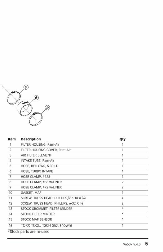
Banks Ram-Air General Assembly
96507 v.4.0 5
2
11
1314
85
84
10
15
12
7
3
1
9
6
9
Item Description Qty
1 FILTER HOUSING, Ram-Air 1
2 FILTER HOUSING cOVER, Ram-Air 1
3 AIR FILTER ELEMENT 1
4 INTAKE TUBE, Ram-Air 1
5 HOSE, BELLOWS, 5.30 I.D. 1
6 HOSE, TURBO INTAKE 1
7 HOSE cLAMP, #128 1
8 HOSE cLAMP, #88 w/LINER 2
9 HOSE cLAMP, #72 w/LINER 2
10 GASKET, MAF 1
11 ScREW, TRUSS HEAD, PHILLIPS,5⁄16-18 X 3⁄4 4
12 ScREW, TRUSS HEAD, PHILLIPS, 6-32 X 3⁄8 2
13 STOcK GROMMET, FILTER MINDER *
14 STOcK FILTER MINDER *
15 STOcK MAF SENSOR *
16 TORX TOOL, T20H (not shown) 1
*Stock parts are re-used
6 96507 v.4.0
Use caution when working in the engine compartment. Make sure the engine has been OFF for several hours and cool. Disconnect the ground cables from both the driver and passenger side batteries. Position the loose cables so that they do not come into contact with their respective battery posts during the installation.
1. Loosen the hose clamp from the stock intake tube on the turbo intake.
2. Loosen and separate the stock hose clamp on the intake air tube connected to the stock air box cover. See Figure 1.
3. Separate the stock intake tube connected to the turbo intake. Remove the stock intake tube from the engine and set aside.
4. Remove the Mass Air Flow (MAF) sensor connector from stock air box filter cover.
Note: Be careful not to damage the connector or the MAF sensor during this process.
5. Remove stock air box by lifting the air box up and out. The bottom of the stock air box is held in place by rubber grommets. There may be some slight resistance when removing the stock air box.
6. Next, remove the stock air box bolts accessible from the top of the engine compartment as shown. Then remove the stock air box tray. See Figure 2. Keep the previously removed bolts for reassembly later in the installation process.
If you are installing the Banks Techni-Cooler, skip to Section 3.
7. Locate your Banks Ram-Air filter housing from your kit. Align the Banks Ram-Air filter housing to fit parallel to fender edge. Install and tighten the
Figure 1
96507 v.4.0 7
previously removed air box tray bolts to secure the Banks Ram-Air filter housing.
Note: The cutout on Banks Ram-Air filter housing must face passenger side fender. See Figure 3.
8. Locate your Banks Torx tool, T20H in your Banks Ram-Air kit. Use the Torx tool bit to remove the two (2) screws securing the MAF sensor to the stock air box cover.
Note: Be careful when removing the MAF Sensor. When removing the MAF sensor, grasp its body and pull up and out. Do not twist or bend when removing.
9. Remove stock MAF gasket. Locate the Banks MAF sensor gasket supplied in your kit. Install Banks gasket as shown (Figure 4).
10. Locate your Banks Ram-Air intake tube in your kit. Install the stock MAF sensor (with the additional Banks
gasket) to MAF sensor mounting boss as shown. Tighten the screws (included) to 3 in/lbs.
Note: Ensure correct alignment, otherwise screw holes will not align with screw holes in the Banks Ram-Air intake tube.
CAUTION: Do not over tighten screws.
11. From the stock air box, remove the stock air filter Minder. Make sure to remove the stock air filter Minder’s rubber grommet as well. See Figure 5.
12. Locate the Banks Ram-Air filter housing cover. Install the air filter Minder’s rubber grommet into the Banks Ram-Air filter housing cover. Once the rubber grommet is installed flush into the Banks Ram-Air cover, then the filter Minder can be inserted into the rubber grommet. Make sure the air filter Minder is installed flush to rubber grommet.
Figure 2
8 96507 v.4.0
Figure 3
Figure 4
96507 v.4.0 9
13. Locate the Banks Ram-Air filter element and the Banks air filter hose clamp. Loosely fit the filter clamp to the air filter element.
Note: See Figure 6 to reference the correct alignment groove to the Banks Ram-Air filter.
14. After verifying the alignment between the Banks Ram-Air filter and the Banks Ram-Air cover, press fit the two pieces together until an audible snap is heard. This process will ensure that a correct seal has been established.
15. Tighten the Banks Ram-Air filter hose clamp to the Banks Ram-Air filter cover.
16. Place the Banks Ram-Air filter cover onto the Banks Ram-Air housing. Align and loosely fit the cover onto the housing.
17. Install, but do not tighten, the Banks bellows hose and hose clamp onto the Banks Ram-Air housing cover.
18. Locate the Banks turbo intake hose, tube, and hose clamps from your
Banks Ram-Air kit. Loosely assemble the Banks intake hose to the Banks intake tube with the supplied hose clamps. Attach the turbo intake hose to the turbo intake tube. Leave the hose clamps loose.
19. Install the Banks Ram-Air intake tube into the Banks bellows. Tighten all the hose clamps to secure the Banks intake tube. See Figure 7.
CAUTION: Ensure intake tube is not touching any engine components.
20. Fasten the Banks air filter cover to the Banks air filter housing using the Banks cover screws and tighten.
21. Re-attach the MAF sensor connector to the MAF sensor in the Banks intake tube.
22. Make sure to check all hose clamps for tightness and connectors for a sure fit. Make sure that the intake tube is not touching any engine components.
-END, SEcTION 1-
Figure 5
10 96507 v.4.0
Figure 6
Figure 7
96507 v.4.0 11
NotificationThe Banks Ram-Air Filter comes pre-oiled and no oiling is necessary for initial installation. Service the filter as specified in this Section.
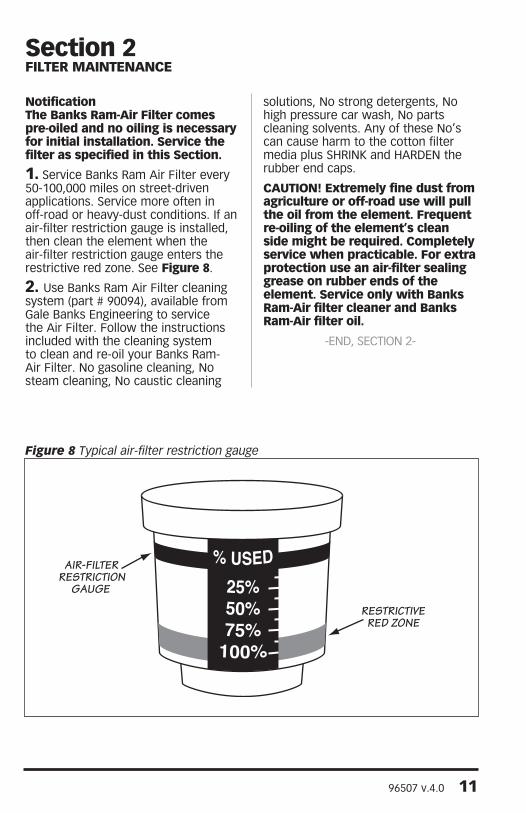
1. Service Banks Ram Air Filter every 50-100,000 miles on street-driven applications. Service more often in off-road or heavy-dust conditions. If an air-filter restriction gauge is installed, then clean the element when the air-filter restriction gauge enters the restrictive red zone. See Figure 8.
2. Use Banks Ram Air Filter cleaning system (part # 90094), available from Gale Banks Engineering to service the Air Filter. Follow the instructions included with the cleaning system to clean and re-oil your Banks Ram-Air Filter. No gasoline cleaning, No steam cleaning, No caustic cleaning
solutions, No strong detergents, No high pressure car wash, No parts cleaning solvents. Any of these No’s can cause harm to the cotton filter media plus SHRINK and HARDEN the rubber end caps.
CAUTION! Extremely fine dust from agriculture or off-road use will pull the oil from the element. Frequent re-oiling of the element’s clean side might be required. Completely service when practicable. For extra protection use an air-filter sealing grease on rubber ends of the element. Service only with Banks Ram-Air filter cleaner and Banks Ram-Air filter oil.
-END, SEcTION 2-
Section 2FILTER MAINTENANCE
AIR-FILTERRESTRICTION
GAUGE
RESTRICTIVERED ZONE
Figure 8 Typical air-filter restriction gauge
12 96507 v.4.0
Section 3BANkS TECHNI-COOLER INSTALLATION
REMOVE STOCk INTERCOOLER
1. Remove the upper grill baffle that mounts between the grill and radiator cross brace. The baffle is held in place by 7 push-in retainers. The retainers are removed by pulling up on the center pin, then prying the retainer out of it’s hole as shown in Figure 9.
2. Remove the grill by disengaging the 8 clips at the outboard ends of the grill and 4 bolts located on top of grill.
3. Remove the 6 pushpin fasteners and bolts from both driver’s and passenger’s side fenderwells.
Note: The fasteners are accessed through the wheel arch opening. Pull the fenderwells down approximately 6 inches once the fasteners are removed. Disconnect the wire harness retaining clips on top of the fenderwell, and then remove the fenderwells from the vehicle.
4. Disconnect the connectors from headlamp assemblies and remove the headlamp assemblies. The headlamp assembly are secured with 3 bolts. Remove the bolts to the headlamp assembly.
Next, remove the bolts (3 per side) to the headlamp assembly / grill support bracket. See Figure 10. Disconnect the connectors from the backside of the headlamp assembly from both drivers and passenger headlamp assemblies. Remove the headlamp assemblies.
Slide the headlamp assembly toward the center and forward of the vehicle to remove. The turn signals are built into the headlamp assembly.
5. Remove the two bolts that secure the upper fan shroud to the upper radiator cross brace. Remove the four push-in retainers (2 per side) that attach the upper section to the lower section of the fan shroud. These retainers are removed by pulling up on the center pin then prying the entire retainer assembly out as shown in Figure 9.
6. Carefully remove the transmission module from the upper fan shroud. Lay the module to the side. See Figure 11.
7. Remove the low pressure A/C condenser line from the line retainer attached to the upper fan shroud.
8. Remove the upper section of the fan shroud from the vehicle. Take care not to damage the face of the radiator when removing the shroud.
9. Remove the two upper condenser mounting bolts that attach to the radiator cross brace.
10. Mark the location of the hood latch, then remove the hood latch from the latch support. The latch is held in place by three bolts. The latch support is shown in Figure 12. It is not necessary to remove the cable from the latch, just place the latch and cable assembly out of the way.
11. Remove the two bolts that attach the latch support to the radiator cross brace and the 4 lower attachment bolts (2 per side). The two bolts that attach the upper support to the radiator cross brace are accessed from the engine compartment side of the vehicle.
12. Only Remove the (2) top oil cooler brackets to free the oil cooler from the latch support bracket. See Figure 12.
96507 v.4.0 13
Figure 10 Headlamp Assembly/Grill support bracket
Figure 9 Removal of push-in retaining pins
14 96507 v.4.0
Figure 11 Transmission module
Figure 12
96507 v.4.0 15
13. Swing the latch support forward as shown in Figure 13.
14. Pull the air conditioning condenser out of it’s lower mounts, and place it against the latch support.
15. Remove the two upper Charge Air Cooler (CAC) mounting bolts and unfasten the fender support rod from the cross brace as shown in Figure 14.
16. Remove the 6 bolts (3 per side) that secure the radiator cross brace. The cross brace is shown in Figure 14. The bolts are on the bottom side at each end of the support. Remove the cross brace from the vehicle.
17. Remove the air box support bracket shown in Figure 15. There is an a/c condenser line retaining clip and a plastic fastener that attaches to the inner fenderwell that must be removed before the bracket can be liberated from the vehicle.
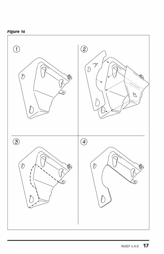
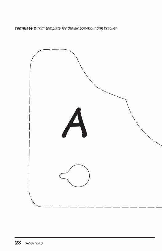
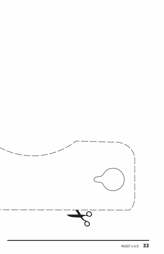
18. Trim the air box support bracket per the supplied templates (Templates 1, 2) in the center of this manual. Figure 16 shows the bracket before and after trimming.
19. Loosen the driver side boost tube hose clamps (Figure 17). Remove the boost tube off the charge air cooler (CAC). Do not damage the hoses that attach to the charge air cooler (CAC), as it will be reused. Cover the hose opening to prevent foreign debris from entering.
20. Remove the passenger side boost tube hose. Use a hook or small screwdriver to remove wire-retaining clip (Figure 18). Remove the lower, then the upper wire-retaining clip. Use a prying device to detach lower coupling hose connection. Pull off by twisting upper hose coupler (Figure 19). Cover the intake manifold and turbocharger discharge to prevent foreign debris from entering during the installation.
21. Remove the radiator attachment bolts. There are four 13mm socket bolts securing the radiator.
22. Lift the radiator out of it’s lower saddle mounts and position it towards the engine so that it is no longer attached to the charge air cooler. Take care not to damage the radiator cooling fins.
23. Remove the charge air cooler from the vehicle. Check that the lower mounting peg grommets are removed from the stock intercooler and placed to the side. The lower rubber grommet will be transferred to the Banks Techni-Cooler in the next step.
Figure 17 Drivers side boost hose
96507 v.4.0 19
Figure 18 Passenger side boost tube
Figure 19 Passenger side boost tube
20 96507 v.4.0
INSTALL BANkS TECHNI-COOLER
24. Locate the supplied Banks Techni-Cooler and transfer both top and bottom rubber grommets and corresponding metal sleeve into position on the Banks charge air cooler.
25. Install the Banks CAC into the vehicle. Align the lower CAC mounting pegs with the rubber mounts in the vehicle’s frame. There is a significant amount of play in the rubber mounts that can allow them to be aligned with the CAC as required.
26. Reinstall the radiator cross brace. Leave the attachment bolts loose to aid in aligning the CAC with the support.
27. Reinstall the radiator onto CAC. Secure the radiator to the Banks CAC with 5∕16”-18 x 11∕8 bolts and large OD washers supplied in the Banks system. Tighten to 10-12 ft-lbs.
Note: Install the top two bolts 1st then install the bottom two bolts. It may be helpful to use a pry bar or similar to assist in aligning the screw holes between the radiator and the Banks Techni-Cooler.
28. Install the upper CAC attachment bolts that were previously removed. There is enough play in the lower mounting pads that the CAC can be positioned to align with the upper cross brace. Tighten the bolts.
29. Tighten the 6 radiator-cross brace bolts to 80 in-lbs. Install the diagonal fender support brace and tighten the bolts.
30. Install the upper fan shroud. The push-in retainers that secure the upper shroud to the lower shroud are secured by inserting the retainer with the center pin pulled out. Once the retainer is inserted, press the center pin down to secure the retainer. Install the stock upper fan shroud bolts and tighten to 80 in-lbs.
Note: Check that the engine-cooling fan can freely spin without contacting the lower fan shroud. If the fan contacts the shroud, the shroud must be realigned with the radiator.
31. Install the transmission control module to the upper fan shroud.
32. Install the a/c condenser and tighten it’s upper mounting bolts to 80 in-lbs.
33. Install the latch support. Tighten it’s six attachment bolts to 80 in-lbs.
34. Install the hood latch. Position it so that it aligns with the marks that were made on the latch support prior to it’s removal. Tighten it’s bolts to 80 in-lbs.
35. Install the driver and passenger side plastic headlamp support structures. Tighten the screws to 80 in-lbs.
36. Install the light bulbs into the park/turn signal lamp assemblies. These are held in place by turning them clockwise. Install the park/turn signal lamp assembly onto the vehicle for both the driver and passenger side.
37. Install the electrical connectors to the headlamp assembly. Install the headlamp assemblies and secure them with their retaining pins.
96507 v.4.0 21
38. Install the grill by snapping in the tabs into the retainer clips.
39. Install the upper grill baffle and secure with the seven push-in retainers that were previously removed. The push-in retainers that secure the grill baffle are secured by inserting the retainer with the center pin pulled out. Once the retainer is inserted, press the center pin down to secure the retainer.
40. Before slipping any boost tubes and the corresponding hoses into position, ensure that all connection ends are clean and free of any oil residue and contaminates. Clean the compressor outlet and all connection points with a non-oil based solvent such as Acetone, Mineral Spirits, Denatured Alcohol or Lacquer Thinner. Read and follow the manufactures operation instruction for non-oil based solvent cleaner.
Note: Make sure to remove any rags or items that were used to cover the turbo and intake manifold openings before installing the boost tubes.
41. Install the driver and passenger side boost tubes. Tighten the driver side hose clamps to 75 in-lbs. Make sure when reinstalling the passenger side boost tube that the hose coupler fits tight and flush to its respective mounting location, then reinstall the wire retaining clip.
Note: The a/c line that runs near the intake manifold will need to be bent downward to provide clearance for the boost tube. The a/c line can be bent by placing a wooden block on the a/c line, then lightly tapping the block with a hammer.
42. Install the lower air cleaner support bracket. Tighten the bolts to 80 in-lbs.
Return back to Section1, step 7.
-END, SEcTION 3-
22 96507 v.4.0
The Banks EconoMind Diesel Tuner has six power levels adjustable by the supplied EconoMind Switch, or six power levels adjustable by the optional Banks PowerPDA.
Level 1 is stock and level 6 is max power. Each additional higher level adds approximately 20% of the available power increase.
WARNING: The PDA may be susceptible to damage as a result of extended exposure to sunlight, heat or extreme cold. It is highly recommended that the PDA be removed from it’s mounting location if the vehicle will be subjected to high concentrations of sunlight, heat or cold for an extended period of time. Gale Banks Engineering is not responsible for damage to PDAs resulting from exposure conditions.
Description Kit
w/PDA option
w/Switch
Module, EconoMind Diesel Tuner 1 1
Switch Kit 1
Cable Ties, 7” 15 20
PowerPDA Docking Station Kit 1
SD card, Programmed 1
Universal Mount Kit 1
OBD-II Interface Cable 1
Thermocouple 1
Cable Tie, 5” 5
Cable Tie, 11” 1
Optional Part NumberPalm Tungsten E2 PDA 61004
Gauges, Boost and Pyro 64507
Section 4INSTALLATION OF WIRING HARNESS, CONNECTIONS AND ECONOMIND DIESEL TUNER
96507 v.4.0 23
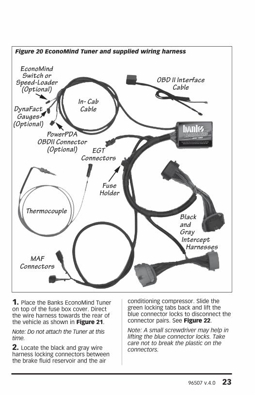
1. Place the Banks EconoMind Tuner on top of the fuse box cover. Direct the wire harness towards the rear of the vehicle as shown in Figure 21.
Note: Do not attach the Tuner at this time.
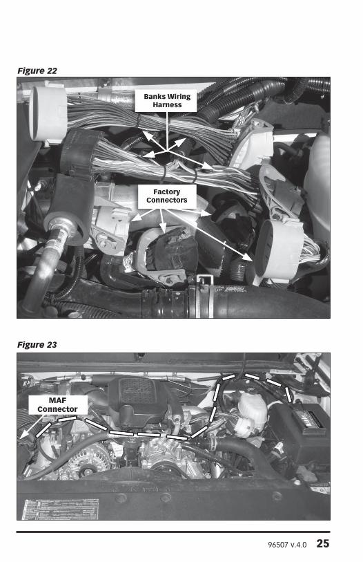
2. Locate the black and gray wire harness locking connectors between the brake fluid reservoir and the air
conditioning compressor. Slide the green locking tabs back and lift the blue connector locks to disconnect the connector pairs. See Figure 22.
Note: A small screwdriver may help in lifting the blue connector locks. Take care not to break the plastic on the connectors.
Figure 20 EconoMind Tuner and supplied wiring harness
24 96507 v.4.0
Note: It may be necessary to open the wire harness retainer clip(s) with a screwdriver for added slack when joining the connectors together.
3. Insert the male gray connector on the EconoMind harness into the female gray connector on the factory harness. Insert the female gray connector on the EconoMind harness onto the male gray connector of the factory harness. Repeat this process with the black connectors. See Figure 22.
4. Go to the air box and remove the stock mass air flow (MAF) connector located on the elbow of the air box cover and set aside.
5. Locate the MAF connector from the EconoMind Tuner harness and route as shown in Figure 23. Follow the factory harness located on top of the engine that runs in front of the intake manifold and behind the alternator.
6. Connect the EconoMind Tuner’s (female) MAF connector to the factory (male) MAF sensor and connect the factory (female) MAF connector to the EconoMind’s (male) MAF connector.
7. Locate the rubber grommet on the driver’s side of the vehicle firewall. The grommet is about 3” in diameter. Make a 1” x 1” cross-shaped (X) incision in the grommet. Be careful so you do not cut the factory harness.
8. From inside the cab locate the grommet on the firewall and make another 1” x 1” cross-shaped (X) incision on the grommet, opposite the spot that was cut from the outside. Now, feed the In-Cab cable through the incision made in the firewall grommet and into the cab (Figure 24).
Note: Some thick putty may be used to provide additional sealing around the In-Cab cable and the grommet.
Figure 21
96507 v.4.0 25
Figure 23
Figure 22
26 96507 v.4.0
9. Position the Tuner on the fuse box cover for an idea of where to clean. The Tuner must be mounted as close to the inside (engine side) edge as possible to avoid a hood clearance issue. Check the hood clearance before attaching the Tuner to the fuse box. Clean the top of the fuse box cover located on the drivers’ side of the engine compartment. Make sure the outside of the fuse box is free of oil, grease and dirt.
Note: Clean the fuse box cover with a non-oil based solvent such as Acetone, Mineral Spirits, Denatured Alcohol or Lacquer Thinner. Read and follow the manufacture’s operation instruction for non-oil based solvent cleaner.
WARNING: Make sure to place the Tuner as shown in Figure 20 to avoid a clearance issue when closing the hood. Mount the EconoMind Tuner as close to the inside (engine side) edge of the fuse cover as possible. Verify
you have hood clearance before mounting the Tuner.
10. Peel the protective backing from the hook and loop interlocking fasteners attached to the EconoMind Diesel Tuner. Position the side edge of the EconoMind Diesel Tuner to the edge closest to the engine of the fuse cover, then press the adhesive onto the outside of the fuse box cover. Apply light pressure to the EconoMind Diesel Tuner by hand for 60-seconds to create a strong bond between the fuse box and hook & loop interlocking fasteners. Using the supplied cable ties, secure the wire harness away from any heat sources or moving components.
CAUTION: When securing the wires, do not bend them any tighter than a 2.5” diameter bend as this can cause undue stress on the wires and may cause failure.
-END, SEcTION 4-
Figure 24
96507 v.4.0 27
This page left blank intentionally
28 96507 v.4.0
A
Template 2 Trim template for the air box-mounting bracket.
96507 v.4.0 29
This page left blank intentionally
30 96507 v.4.0
TRIM BRACKET ALONG THIS LINE
ALIGN WITH BRACKET BEND
ALIGN
WITH
BRACKET EDGE
TRIM
BRA
CKET
ALO
NG
TH
IS L
INE
ALIGN WITH BRACKET CORNER
B
Template 1 Trim template for the air box-mounting bracket.
96507 v.4.0 31
TRIM BRACKET ALONG THIS LINE
ALIGN WITH BRACKET BEND
ALIGN
WITH
BRACKET EDGE
TRIM
BRA
CKET
ALO
NG
TH
IS L
INE
ALIGN WITH BRACKET CORNER
B
32 96507 v.4.0
This page left blank intentionally
96507 v.4.0 33
A
34 96507 v.4.0
This page left blank intentionally
96507 v.4.0 35
If not installing the optional Banks PowerPDA, skip to Section 25.
1. Locate the universal mount and docking station in your kit. Interlock the docking station to the universal mount by inserting and sliding the universal mount tabs into the docking station grooves. See Figure 25.
2. Install the Banks PowerPDA into the docking station. Be sure the PowerPDA is completely seated in the docking station against the lower support bracket.
Note: There may be a snug fit when installing the PowerPDA into the docking station. Take care not to force this process.
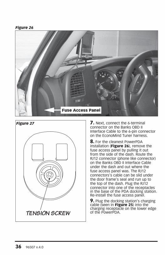
3. Find a smooth, flat surface suitable for ease of access and viewing of the PowerPDA. See Figure 26 for an example. Loosen both knobs and move the swivel suction plate and docking station to achieve desired viewing angle of the PowerPDA screen. Do a test fit and note the angle necessary to achieve the correct viewing angle.
4. Tighten both knobs to lock in the position (Figure 25).
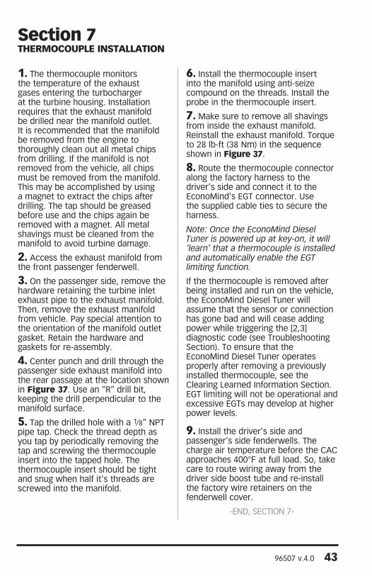
Note: If the universal mount swivel does not move or is tight after loosening the hold down knob, then remove the previously inserted docking station and slightly loosen the tension screw. See Figure 27.
5. With the alcohol swab from your kit, clean the suction cup and the mounting area and let dry. With the suction lever in the up position ensure the suction cup is flat against the windshield or smooth, flat surface. Then, push the suction lever down to secure in place.
6. Find the Banks OBD II Interface Cable in your kit. Connect the Banks Interface Cable to the vehicle’s OBD II connector. Use a cable tie as shown in Figure 28 to secure the Banks Interface Cable to the vehicle’s OBD II connector.
Section 5MOUNTING THE (OPTIONAL) DOCkING STATION AND CONNECTING THE BANkS POWERPDA
Figure 25
CHARGINGCABLE
36 96507 v.4.0
7. Next, connect the 6-terminal connector on the Banks OBD II Interface Cable to the 6-pin connector on the EconoMind Tuner harness.
8. For the cleanest PowerPDA installation (Figure 26), remove the fuse access panel by pulling it out from the side of the dash. Route the RJ12 connector (phone like connector) on the Banks OBD II Interface Cable under the dash and out where the fuse access panel was. The RJ12 connectors’s cable can be slid under the door frame’s seal and run up to the top of the dash. Plug the RJ12 connector into one of the receptacles in the base of the PDA docking station. Re-install the fuse access panel.
9. Plug the docking station’s charging cable (seen in Figure 25) into the charging receptacle on the lower edge of the PowerPDA.
Figure 27
Figure 26
96507 v.4.0 37
WARNING: The charging cable on the docking station is designed to supply a constant low-voltage power source (+5vdc) to the Banks PowerPDA and is “live” as long as the system’s OBD II Interface Cable is completely installed and the RJ12 connector is plugged into the docking station. Although this charging cable is short and it’s circuitry is fuse protected, the user is expected to take appropriate measures to prevent small children and/or pets from contact with any part of this system.
10. Route all wiring away from any pedals or other moving components. Using the cable ties supplied, secure the wiring under the dash.
11. Double check everything to make sure it is securely fastened and it is not near any hot or moving parts before starting engine.
12. Set up the Banks PowerPDA according to it’s instructions.
WARNING: The PDA may be susceptible to damage as a result of extended exposure to sunlight, heat or extreme cold. It is highly recommended that the PDA be removed from it’s mounting location if the vehicle will be subjected to high concentrations of sunlight, heat or cold for an extended period of time. Gale Banks Engineering is not responsible for damage to PDA’s resulting from exposure conditions.
-END, SEcTION 5-
Figure 28
38 96507 v.4.0
Not needed if the optional Banks PowerPDA is installed.
CAUTION: Do not use force when working on plastic parts. Permanent damage to the part may result.
Note: Before drilling, confirm that there is adequate room for the Switch and wires behind the dash. Make sure wires or obstructions are cleared from the drilling area.
From where the EconoMind Switch will be located, make sure there is enough wire on the In-Cab Cable to reach the Switch.
1. The EconoMind Switch can be installed on the driver’s side of the instrument panel (IP) to the left side of the steering column. There are two dash types: Dash 1 (Figures 29, 30) and Dash 2 (Figures 31, 32).
Note: These are just suggested locations. It is possible to locate the EconoMind Switch where it is more comfortable. Please confirm space behind dash before drilling.
2. To install on the driver’s side IP (Dash 1, Figure 29):
Pull the IP trim out by pulling the top edge above the vent as shown in Figure 33. Disconnect any switch wires.
3. Cut out the supplied template, Figure 16, and align the dashed lines to the edge of the IP where you would like to mount the Switch. Tape the template in place. continue to Step 7.
4. To install the Switch to the left side of the steering column (Dash 2 Figure 32):
Remove the fuse access panel shown in Figure 26. Remove the lower knee bolster panel by removing the
Section 6INSTALLATION OF THE (OPTIONAL) ECONOMIND SELECTOR SWITCH
Figure 29 Figure 30
96507 v.4.0 39
Figure 31 Figure 32
Figure 33
40 96507 v.4.0
2 Phillips screws on the lower edge of the panel. Using a 10mm socket and ratchet, unbolt the brake release lever. Pull the panel out by grasping it on either side of the steering column and pull out as shown in Figure 34. Disconnect any switch wires.
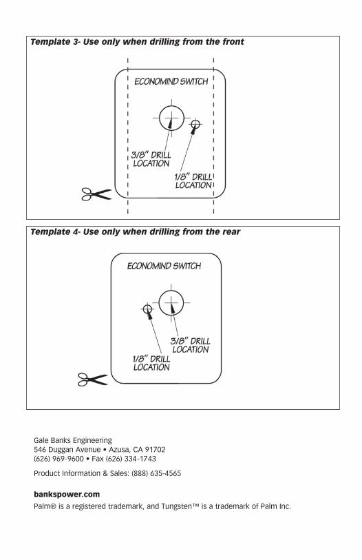
5. Cut out the supplied template, Template 3 in the back of the manual, and align the template to the right edge of the IP to the left of the steering column. Tape the template in place. A 90° drill will be needed to drill the hole. Continue to Step 7.
6. To install Switch as shown in Figures 30 & 31:
Follow Step 4 to remove the IP for both Dash styles. Cut out the supplied template, Template 4 in the back of the manual, and align the template onto the rear of the knee bolster, squarely seating it into the panel corner as shown in Figure 35.
7. Using a 3⁄8” Uni-bit step drill bit or a 3⁄8” drill bit, center the bit onto the 3⁄8” drill location on the template and slowly drill through the IP. Using a 1⁄8” drill bit, center and drill through the 1⁄8” location on the template. Remove and discard the template and any plastic shavings.
8. On the front side of where the Switch will be mounted, clean the area with some alcohol and allow it to dry. Remove the backing from the EconoMind Label and align it over the previously drilled hole.
9. Remove the nut and internal tooth washer from the EconoMind Switch. Rotate the shaft counter clockwise until the shaft stops. Verify the locating washer tab is inserted into the #6 position on the Switch (Figure 36).
NOTE: If the washer is in any position other then the #6, your EconoMind Diesel Tuner will not select power levels properly.
Figure 34
96507 v.4.0 41
Figure 35- Rear template used
Figure 36
42 96507 v.4.0
10. After confirming the locating washer is in the #6 location, install the Switch through the 3⁄8” hole. The alignment pin should rest in the 1⁄8” hole. With the Switch fully rotated counter clockwise the shaft’s flat side should be facing the driver’s side door. Secure the Switch with the internal tooth washer and nut. Snug the washer; be careful not to over torque the nut and damage the plastic threads.
11. Install the knob onto the shaft facing the #1 Level on the EconoMind label. On the knob, snug the two (2) set screws with the supplied 0.050” hex key wrench.
12. Route the EconoMind Switch Cable down to the EconoMind Diesel Tuner’s In-Cab Cable underneath the dashboard, and reinstall any panel(s) that were removed.
Note: Take care to keep any cables away from the pedals or where they could become tangled.
13. Connect the EconoMind Switch’s 2-terminal receptacle to the 2-terminal plug on the EconoMind Diesel Tuner’s In-Cab Cable.
-END, SEcTION 6-
Figure 37
96507 v.4.0 43
1. The thermocouple monitors the temperature of the exhaust gases entering the turbocharger at the turbine housing. Installation requires that the exhaust manifold be drilled near the manifold outlet. It is recommended that the manifold be removed from the engine to thoroughly clean out all metal chips from drilling. If the manifold is not removed from the vehicle, all chips must be removed from the manifold. This may be accomplished by using a magnet to extract the chips after drilling. The tap should be greased before use and the chips again be removed with a magnet. All metal shavings must be cleaned from the manifold to avoid turbine damage.
2. Access the exhaust manifold from the front passenger fenderwell.
3. On the passenger side, remove the hardware retaining the turbine inlet exhaust pipe to the exhaust manifold. Then, remove the exhaust manifold from vehicle. Pay special attention to the orientation of the manifold outlet gasket. Retain the hardware and gaskets for re-assembly.
4. Center punch and drill through the passenger side exhaust manifold into the rear passage at the location shown in Figure 37. Use an “R” drill bit, keeping the drill perpendicular to the manifold surface.
5. Tap the drilled hole with a 1⁄8” NPT pipe tap. Check the thread depth as you tap by periodically removing the tap and screwing the thermocouple insert into the tapped hole. The thermocouple insert should be tight and snug when half it’s threads are screwed into the manifold.
6. Install the thermocouple insert into the manifold using anti-seize compound on the threads. Install the probe in the thermocouple insert.
7. Make sure to remove all shavings from inside the exhaust manifold. Reinstall the exhaust manifold. Torque to 28 lb-ft (38 Nm) in the sequence shown in Figure 37.
8. Route the thermocouple connector along the factory harness to the driver’s side and connect it to the EconoMind’s EGT connector. Use the supplied cable ties to secure the harness.
Note: Once the EconoMind Diesel Tuner is powered up at key-on, it will ‘learn’ that a thermocouple is installed and automatically enable the EGT limiting function.
If the thermocouple is removed after being installed and run on the vehicle, the EconoMind Diesel Tuner will assume that the sensor or connection has gone bad and will cease adding power while triggering the [2,3] diagnostic code (see Troubleshooting Section). To ensure that the EconoMind Diesel Tuner operates properly after removing a previously installed thermocouple, see the clearing Learned Information Section. EGT limiting will not be operational and excessive EGTs may develop at higher power levels.
9. Install the driver’s side and passenger’s side fenderwells. The charge air temperature before the CAC approaches 400°F at full load. So, take care to route wiring away from the driver side boost tube and re-install the factory wire retainers on the fenderwell cover.
-END, SEcTION 7-
Section 7THERMOCOUPLE INSTALLATION
44 96507 v.4.0
1. Raise the vehicle and support it with properly weight rated safety stands, ramps, or a commercial hoist. Follow the manufacturer’s safety precautions. Take care to balance the vehicle to prevent it from slipping or falling. When using ramps, be sure the front wheels are centered squarely on the topsides; place the transmission in park; set the parking brake and place blocks behind the rear wheels.
CAUTION: Do Not Work Under Any Vehicle Supported Only By A Jack. Severe Injury May Result.
WARNING! The following step may require the use of a torch and/or saw. Proper safety equipment should be used. Failure to use proper safety equipment may result in severe injury.
2. Removal of the factory exhaust can be simplified by cutting the factory exhaust pipe behind the muffler. This will allow the tailpipe to be removed as a separate piece.
3. Remove the factory tailpipe from the vehicle by disengaging the exhaust system hanger pins from the rubber hangers using a large screw-driver or pry bar.
Note: Lubricating the rubber hangers with WD-40 or similar lubricant will ease removal of the hanger pins.
4. Remove the factory muffler from the vehicle by removing the three (3) nuts from the factory exhaust flange located at the factory muffler inlet.
5. Install the Banks flanged intermediate pipe and 3-bolt gasket onto the headpipe. Loosely assemble with the supplied bolts, washers, and nuts.
6. Slide the supplied 4” exhaust hanger clamp onto the outlet of the Banks flanged intermediate pipe. Insert
the hanger pin into the factory rubber hanger.
7. Route the front tailpipe over the rear axle housing and install onto the flanged intermediate pipe outlet. Be sure that the two pipes are completely engaged. Loosely snug the 4” hanger clamp.
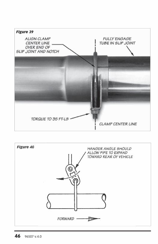
8. Install a 4” exhaust clamp onto the inlet of the rear tailpipe. Install the rear tailpipe onto the outlet of the front tailpipe. Insert the rear tailpipe hanger pin into the factory rubber hanger. Rotate the tailpipe until the hanger pins are parallel with the frame mounted pin. Slide the 4” clamp and position as shown in Figure 39. Loosely snug the 4” clamp.
Notes: Maintain an adequate air gap clearance of one (1) inch between the exhaust and the shock absorber and between the exhaust and the spare tire.
Minimum distance between exhaust tip and body is one (1) inch.
9. Adjust each of the pipes to ensure that all of the hanger pins are parallel with the frame mounted pins and that the rubber hangers are all positioned slightly forward (Figure 40). The amount of forward angle on the rubber hangers should increase the farther downstream the hanger is positioned. This allows the hangers to be properly positioned once the exhaust system reaches operating temperature.
10. Figure 39 illustrates the proper location of an exhaust clamp on a tubing joint. Torque the nuts on each of the exhaust clamps to 35 ft-lb.
Note: The clamps only need to be tight enough to form a seal and hold the pipes together. Over tightening the clamps may cause the system to leak due to the pipe being crimped.
Section 8MONSTER ExHAUST SINGLE SySTEM INSTALLATION
96507 v.4.0 45
Fig
ure
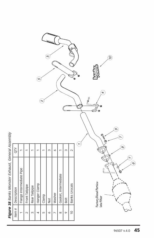
38
Ban
ks M
onst
er E
xhau
st, G
ener
al A
ssem
bly
Item
#D
escr
iptio
nQ
TY
1Fl
ange
Inte
rmed
iate
Pip
e1
2Fr
ont T
ailp
ipe
1
3Re
ar T
ailp
ipe
1
4H
ange
r c
lam
p1
5c
lam
p1
6N
ut3
7W
ashe
r6
8G
aske
t, In
term
edia
te1
9B
olt
3
10B
anks
Uro
cals
2
Fact
ory D
iesel
Part
icu-
late F
ilter
46 96507 v.4.0
Figure 39
Figure 40
96507 v.4.0 47
11. Remove the protective covering from the tailpipe tip.
CAUTION: The protective covering may ignite and burn if not removed prior to running the engine.
12. Your system includes two (2) Banks Power decals designed to complement the Duramax emblems on the vehicles front doors.
13. Re-connect the negative battery cable(s). Start the engine and listen for exhaust leaks. Tighten the exhaust clamps as necessary. Whenever possible, tack weld slip connections to prevent disengagement is recommended. The Banks Monster Exhaust installation is now complete.
-END, SEcTION 8-
Figure 41- Single Exhaust
48 96507 v.4.0
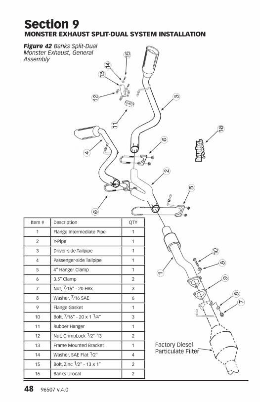
Item # Description QTY
1 Flange Intermediate Pipe 1
2 Y-Pipe 1
3 Driver-side Tailpipe 1
4 Passenger-side Tailpipe 1
5 4” Hanger clamp 1
6 3.5” clamp 2
7 Nut, 7⁄16” - 20 Hex 3
8 Washer, 7⁄16 SAE 6
9 Flange Gasket 1
10 Bolt, 7⁄16” - 20 x 1 1⁄4” 3
11 Rubber Hanger 1
12 Nut, crimpLock 1⁄2”-13 2
13 Frame Mounted Bracket 1
14 Washer, SAE Flat 1⁄2” 4
15 Bolt, Zinc 1⁄2” - 13 x 1” 2
16 Banks Urocal 2
Factory Diesel Particulate Filter
Section 9MONSTER ExHAUST SPLIT-DUAL SySTEM INSTALLATION
Figure 42 Banks Split-Dual Monster Exhaust, General Assembly
96507 v.4.0 49
1. Raise the vehicle and support it with properly weight rated safety stands, ramps, or a commercial hoist. Follow the manufacturer’s safety precautions. Take care to balance the vehicle to prevent it from slipping or falling. When using ramps, be sure the front wheels are centered squarely on the topsides; place the transmission in park; set the parking brake and place blocks behind the rear wheels.
CAUTION: Do Not Work Under Any Vehicle Supported Only By A Jack. Severe Injury May Result.
WARNING! The following step may require the use of a torch and/or saw. Proper safety equipment should be used. Failure to use proper safety equipment may result in severe injury.
2. Removal of the factory exhaust can be simplified by cutting the factory exhaust pipe behind the muffler. This will allow the tailpipe to be removed as a separate piece.
3. Remove the factory tailpipe from the vehicle by disengaging the exhaust system hanger pins from the rubber hangers using a large screw-driver or pry bar.
Note: Lubricating the rubber hangers with WD-40 or similar lubricant will ease removal of the hanger pins.
4. Remove the factory muffler from the vehicle by removing the three (3) nuts from the factory exhaust flange located at the factory muffler inlet.
5. Install the Banks flanged intermediate pipe and 3-bolt gasket onto the headpipe. Loosely assemble with the supplied bolts, washers, and nuts.
6. Slide the supplied 4” exhaust hanger clamp onto the outlet of the Banks flanged intermediate pipe.
7. Install the Y-Pipe over the intermediate pipe as shown in Figure 42. Install the 3.5” clamps onto each Y-pipe outlet.
8. Install the driver-side hanger bracket on the rear driver-side frame rail using the supplied hardware. Be sure the hanger pin is align parallel to the frame rail and torque the hardware to 48ft-lb. See Figure 43.
9. Install the supplied rubber insulator onto the Banks hanger bracket. See Figure 43.
10. Install the driver-side tailpipe onto the left Y-pipe outlet. Install the driver-side tailpipe hanger into the vehicle rubber insulator. Position the rubber insulator as shown in Figure 44.
11. Install the passenger-side tailpipe onto the right Y-pipe outlet. Install the passenger-side tailpipe hanger into the vehicle rubber insulator. Position the rubber insulator as shown in Figure 44.
12. Loosen and move the spare-tire to the rear of the vehicle and center between the dual tailpipes. Securely tighten the spare tire so that it is retained in place see Figure 45.
13. Adjust the tailpipe tips under the rear fender such that the tip position is aesthetically pleasing.
14. With everything positioned properly, begin to tighten the clamps starting with the ones closest to the turbo and working your way back. Evenly torque the exhaust clamps to 35 ft-lbs. Make sure that each slip is fully inserted (+/- 1⁄4 inch). See Figure 46.
50 96507 v.4.0
Figure 43
Figure 44
96507 v.4.0 51
15. Remove the protective covering from the tailpipe tips.
CAUTION: The protective covering may ignite and burn if not removed prior to running the engine.
16. Re-route any vent hose or brake lines away from the tailpipe using the supplied Cable ties.
17. Your system includes two (2) Banks Power decals designed to complement the Duramax emblems on the vehicles front doors.
18. Re-connect the negative battery cable(s). Start the engine and listen for exhaust leaks. Tighten the exhaust clamps as necessary. Whenever possible, tack weld slip connections to prevent disengagement is recommended. The Banks Monster Exhaust installation is now complete.
-END, SEcTION 9-
BANKSDRIVER SIDE
TAILPIPE
ZIP TIE ONVENT HOSE
& BRAKE LINE BANKSPASSENGER SIDE
TAILPIPE
ADJUST SO THATSPARE TIRE TO
TAILPIPE CLEARANCEIS THE SAME MOVE SPARE
TIRE TOWARDSREAR OF VEHICLE
Figure 45
52 96507 v.4.0
Figure 46
Figure 47 Split-Dual Exhaust
96507 v.4.0 53
Note: If a PowerPDA is installed, please refer to the Banks PowerPDA Software & Installation Kit Owner’s Manual for software installation and operation instruction before beginning Section 11, Automatic Transmission Learning.
The 6.6L Chevy Duramax Trucks equipped with the Allison 1000 6-speed automatic overdrive transmission use an adaptive shift control logic. This will require the transmission to adapt to the additional power created by the Banks Power products before it will shift properly. Failure to follow the sequence can result in damage to the transmission.
Perform the following sequence at a location where it is safe to accelerate without exceeding the posted speed limit.
1. Set EconoMind Tuner to Level 1 power setting, start the truck and allow the engine to reach normal operating temperature.
2. Adjust EconoMind to Level 2, power setting.
3. Drive vehicle for 5 to 10 miles ensuring a complete shift cycle though each gear. (The transmission shift adaptation learning process requires 15 to 30 complete shift cycles to learn new shift program.)
4. Increase power level by one and repeat Step 3 until the desired power level is achieved.
WARNING: Take particular care not to do wide open runs in 5th gear when in Automatic transmission Learning Mode.
The Allison 1000 6-speed automatic transmission will continually adapt to the power output of the engine to optimize shift quality. The transmission will quickly adapt to the power setting if the driving cycle includes regular gear changes at high loads. The transmission learning procedure will need to be repeated when switching back to the higher power settings once the transmission adapts to the lower power settings. It will be apparent when the transmission adapts to the lower settings by monitoring the feel of the gearshift. Gear changes will be noticeably harder when initially switching from a higher to lower power setting. This will soften as the transmission adapts to the new setting.
-END, SEcTION 11-
Section 10AUTOMATIC TRANSMISSION LEARNING
54 96507 v.4.0
The EconoMind Diesel Tuner requires the engine coolant temperature (ECT) to be above 110º before it will add fuel. If the optional Banks PowerPDA or DynaFact® gauges are installed, observe the operation of the boost and pyrometer (EGT) gauge values while driving under varying conditions. Turbocharger boost pressure will increase as a function of load and engine RPM, thus the engine will produce little boost while cruising at light throttle, with maximum boost while climbing hills, heavily loaded, and/or during acceleration. Note the boost level seen during hard acceleration with a given load. If performance seems to have deteriorated sometime in the future, the maximum boost figures may be compared to see if boost has dropped off. Lower boost may be caused by turbo ducting leaks, a malfunctioning wastegate or fuel injection pump, or dirty air filter. Typical maximum boost pressure settings will vary considerably between automatic transmissions, year model of vehicle, and altitude.
Note: Before key-off, check the EconoMind Tuner for error codes. Use your Banks PowerPDA or EGT gauge to monitor exhaust gas temperature (EGT) in the engine. At idle, exhaust gas temperature will be very low, perhaps only 300°F. As the engine is accelerated for higher speeds with greater loads, the EGT will rise. The highest EGT will be seen under maximum load at full throttle, such as climbing a steep grade with a heavily laden vehicle. To avoid heat damage to various engine components it is recommended that the exhaust gases cool below 400ºF before the engine is shut down. Your EconoMind Diesel Tuner is calibrated to maintain EGTs depending on power level.
Level EGT
1-6 1350°F
You may experience brief excursions slightly above the temperatures listed under acceleration. This is normal and the EGT should return to or below the proper temperature within a few seconds. If you find that EGT remains high for any length of time, check for boost leaks or a dirty air filter.
-END, SEcTION 12-
Section 11CHECkING ENGINE PERFORMANCE
96507 v.4.0 55
EconoMind troubleshooting using the Banks PowerPDA.
Check the Banks PowerPDA’s Status Indicator for the “OK” icon. Any EconoMind Tuner fault will be indicated by the “Banks Engine” icon (see Figure 48) and it’s cause can be investigated by going to the ‘Self Diagnostics’ screen and scrolling through the list of logged Tuner events.
1. Press the center button on the 5- way navigator (Figure 49) to take you to the System Menu screen.
2. Touch the button labeled ‘More>’ to move to the second screen of the System Menu
3. Next, touch the ‘Self Diagnostics’ button. (See Figure 50)
4. The ‘Self Diagnostics’ screen displays a log of diagnostic events related to the EconoMind Tuner (See Figure 51). The ‘Logged Events’ list takes a moment to update each time this screen is opened (as indicated by a slight flickering of the list). Once the list is updated, the most current event will appear at the top of the list. Each event has an associated time stamp and description, which will be
displayed below the list when that event is highlighted. Each key cycle of the vehicle produces a minimum of two logged events.
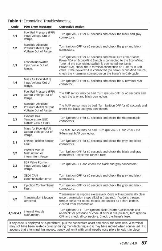
5. Touch the ‘Down’ or ‘Up’ buttons to scroll through the list of recorded events. Table 1 lists the available diagnostic codes and the recommended course of action for each.
6. Touch the center button on the 5- way navigator (or the ‘Back’ button) to return to the System-Monitor screen.
Section 12ECONOMIND TUNER TROUBLESHOOTING
Figure 50
Figure 49
(UP)
(DOWN)
5-WAY NAVIGATOR
Figure 51
ECONOMIND TUNER ICON
Figure 48
56 96507 v.4.0
EconoMind Troubleshooting using the Tuner’s LEDs.
(With or without a Banks PowerPDA Installed)
If you feel that your EconoMind Diesel Tuner is not functioning properly, some diagnostics can be performed. Your EconoMind Diesel Tuner is equipped with diagnostic features that will detect and display certain errors.
Remove the EconoMind Diesel Tuner from it’s mounting location while keeping all connectors plugged in, and position it in such a way that you can view the end of the EconoMind housing that contains the LEDs from the driver’s seat (Figure 52). Turn the vehicle key to the ON position. Observe the two LEDs mounted on the end of the EconoMind Diesel Tuner:
• A steady GREEN LED will illuminate if all wire connections are correct, the engine is running, and the engine coolant temperature is within it’s normal operating range.
• The GREEN LED will flash if all wire connections are correct, the engine is running, but the engine coolant temperature is not within it’s normal operating range. The GREEN LED will stop flashing once the engine coolant temperature is within it’s normal operating range.
• No LEDs will illuminate if the fuse on the EconoMind wiring harness is blown or the wiring harness is not properly connected. If the fuse and all connections are okay, contact Banks Technical Service.
• The RED LED will flash in a certain sequence if a connection is incorrect or if there is a problem with the system – this sequence will identify one or more diagnostic codes. A EconoMind Diesel Tuner’s diagnostic code is comprised of 2 digits. Each code is expressed in a sequence of 2 sets of the flashing RED LED separated by a brief flashing of the GREEN LED in between. Each set of a number of RED LED flashes represents a digit. A longer flashing of the GREEN LED separates the sequences. The LEDs will continue to flash to display all the errors, and then repeat. Table 1 lists common diagnostic codes. For example, if a faulty thermocouple is detected (code “2,3”) by the EconoMind Diesel Tuner, the following RED and GREEN LED flashing sequence is observed when the key is on:
(1) Two times flashing RED LED
(2) One time quick flashing GREEN LED
(3) Three times flashing RED LED
(4) One time longer flashing GREEN LED
The above flashing sequence will repeat continuously. When the problem is corrected, the diagnostic code will be eliminated and replaced by a steady GREEN LED. If the problem persists, contact Banks Technical Service.
NOTE: If multiple codes are set, they will be displayed in a series separated by the longer flashing GREEN LED. When reading codes, make sure to watch the entire series until you see the first code repeat.
Figure 52
96507 v.4.0 57
Code PDA Error Message Corrective Action
1,1Fuel Rail Pressure (FRP) Input Voltage Out of Range.
Turn ignition OFF for 60 seconds and check the black and gray connectors.
1,2Manifold Absolute Pressure (MAP) Input Voltage Out of Range.
Turn ignition OFF for 60 seconds and check the gray and black connectors.
1,3EconoMind Switch Input Value Out of Range.
Turn ignition OFF for 60 seconds and make sure either Banks PowerPDA or EconoMind Switch is connected to the EconoMind Tuner. If the EconoMind Switch is connected (no Banks PowerPDA), check the 2-terminal connection on Tuner’s In-Cab cable. If the PowerPDA is connected (no Banks EconoMind Switch), check the 4-terminal connection on the Tuner’s In-Cab cable.
1,4Mass Air Flow (MAF) Input Voltage Out of Range.
Turn ignition OFF for 60 seconds and check the 5-Terminal MAF connector.
2,1Fuel Rail Pressure (FRP) Output Voltage Out of Range.
The FRP sensor may be bad. Turn ignition OFF for 60 seconds and check the gray and black connectors.
2,2Manifold Absolute Pressure (MAP) Output Voltage Out of Range.
The MAP sensor may be bad. Turn ignition OFF for 60 seconds and check the black and gray connectors.
2,3Exhaust Gas Temperature (EGT) Sensor circuit Fault.
Turn ignition OFF for 60 seconds and check the thermocouple connectors.
2,4Mass Air Flow (MAF) Output Voltage Out of Range.
The MAF sensor may be bad. Turn ignition OFF and check the 5-Terminal MAF connector.
3,1 Engine Position Sensor Fault.
Turn ignition OFF for 60 seconds and check the gray and black connectors.
3,2Internal Module Malfunction or Intermittent Power.
Turn ignition OFF for 60 seconds and check the black and gray connectors. Check the Tuner’s fuse.
3,3EGR Valve Position Input Voltage Out of Range.
Turn ignition OFF and check the black and gray connectors.
3,4 OBDII cAN communication error
Turn ignition OFF for 60 seconds and check the gray and black connectors.
4,1 Injection Control Signal Fault.
Turn ignition OFF for 60 seconds and check the gray and black connectors.
4,2 Transmission Slippage Detected.
Transmission is slipping excessively. Code will automatically clear once transmission stops slipping (repaired). If code is thrown, torque convertor needs to lock and unlock 5x before code is cleared from transmission.
4,3 or 4,4 Internal Module Malfunction.
Turn ignition OFF. Turn ignition back ON after 60 seconds and re-check for presence of code. If error is still present, turn ignition OFF and check all connectors. Check the Tuner’s fuse.
Table 1: EconoMind Troubleshooting
If any code is displayed or is persistent, pull the connectors apart and check the terminals. A terminal may not have been seated correctly during manufacturing and it may have moved when connected. If it appears that a terminal has moved, gently pull on it with small needle nose pliers to lock it in place.
58 96507 v.4.0
If the EconoMind Diesel Tuner has been moved to a different vehicle, or you are instructed to do so by Banks Technical Staff, it is possible to reset all of the parameters that the EconoMind has ‘learned’ - presence of an EGT thermocouple, etc.
CAUTION: The following procedures can only be carried out with the engine OFF!
1. Turn the vehicle key to ON but DO NOT start the engine.
2. Fully depress the throttle pedal and then release it completely. Repeat 5 times. The Tuner’s GREEN LED will flash when this is completed successfully.
3. Turn the key OFF. Wait 60 seconds and make sure the GREEN LED goes off and stays off. Turn the key back to the ON position but DO NOT start the engine.
4. Fully depress the throttle pedal and then release it completely. Repeat 5 times.
5. The EconoMind Tuner has now been cleared of all ‘learned’ parameters and will now be in a factory-default state, as it was originally shipped.
-END, SEcTION 14-
Section 13CLEARING LEARNED INFORMATION
If the EconoMind Diesel Tuner should ever need to be removed from the vehicle, perform the following:
1. Disconnect the negative (ground) cable from the battery (or batteries, if there are two) before beginning work.
2. Disconnect the EconoMind’s gray connector from the factory harness.
3. Re-connect the vehicle’s gray connector back into the factory harness.
4. Disconnect the EconoMind’s black connector from the factory harness.
5. Re-connect the vehicle’s black connector back into the factory harness.
6. Disconnect the EGT thermocouple connector. The thermocouple may be left in place or removed if a suitable plug is used.
7. Disconnect the ‘In-Cab Cable’ and gently pull the cable back through the firewall.
8. Remove the EconoMind Diesel Tuner. Failure to follow the above instructions when removing the Tuner will result in a “Check Engine” light on the dash and a Diagnostic Trouble Code being stored in the factory computer, in addition to the engine not running.
9. Re-connect the negative (ground) cable(s).
-END, SEcTION 15-
Section 14REMOVAL OF THE ECONOMIND DIESEL TUNER
96507 v.4.0 59
Section 15PLACEMENT OF THE BANkS POWER DECALS
TYPICAL LEFT FENDER PLACEMENT
TYPICAL RIGHT FENDER PLACEMENT
Figure 53
Gale Banks Engineering 546 Duggan Avenue • Azusa, cA 91702 (626) 969-9600 • Fax (626) 334-1743
Product Information & Sales: (888) 635-4565
bankspower.com
Palm® is a registered trademark, and Tungsten™ is a trademark of Palm Inc.