Nortel is a recognized leader in delivering communications capabilities that enhance the human experience, ignite and power global commerce, and secure and protect the world’s most critical information. Serving both service provider and enterprise customers, Nortel delivers innovative technology solutions encompassing end-to-end broadband, Voice over IP, multimedia services and applications, and wireless broadband designed to help people solve the world’s greatest challenges. Nortel does business in more than 150 countries. For more information, visit Nortel on the Web at www.nortel.com.
Abstract The purpose of this TCG is to review the many options available on Nortel Ethernet and Ethernet Routing Switches for interoperability with Nortel’s IP Phone sets.
Conventions This section describes the text, image, and command conventions used in this document.
Symbols
Tip – Highlights a configuration or technical tip.
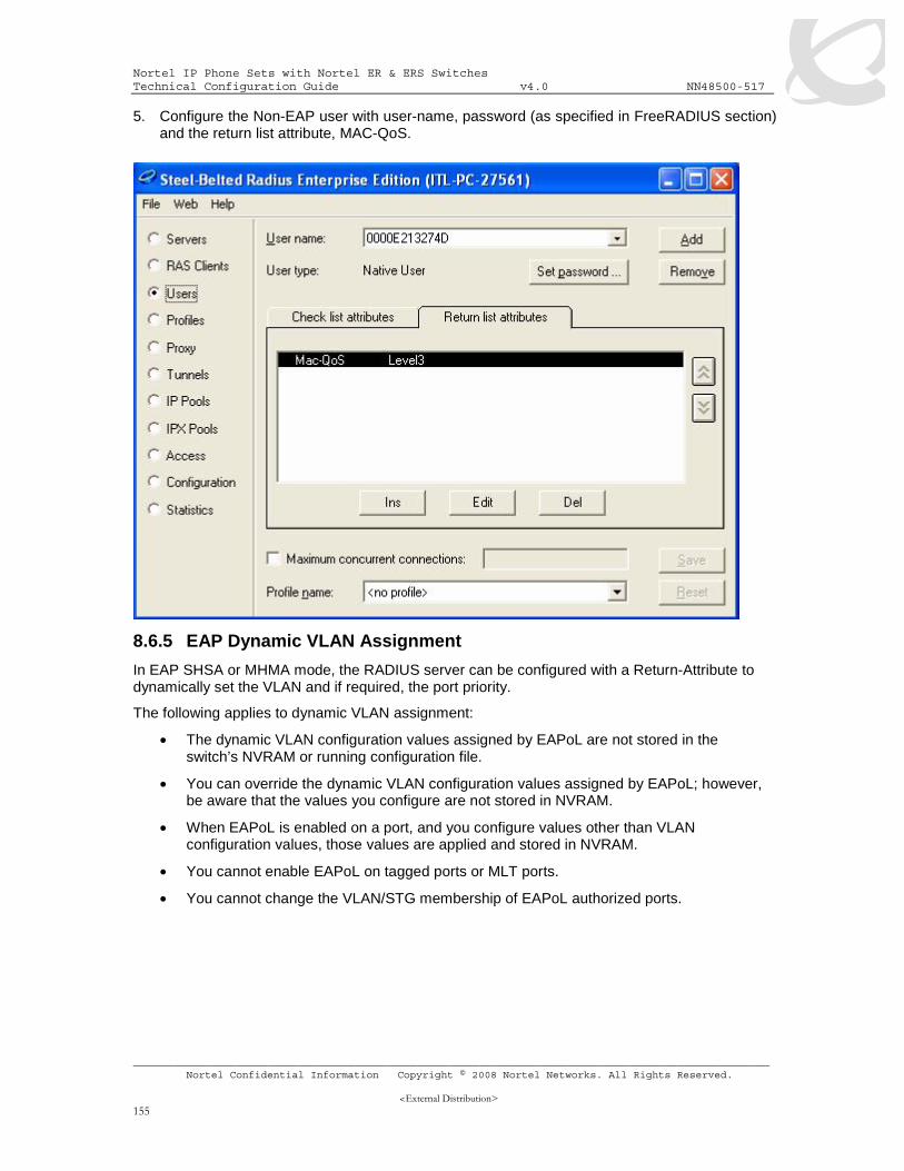
Note – Highlights important information to the reader.
Warning – Highlights important information about an action that may result in equipment damage, configuration or data loss.
Text
Bold text indicates emphasis.
Italic text in a Courier New font indicates text the user must enter or select in a menu item, button or command:
ERS5520-48T# show running-config
Output examples from Nortel devices are displayed in a Lucida Console font:
ERS5520-48T# show running-config
! Embedded ASCII Configuration Generator Script
! Model = Ethernet Routing Switch 5520-24T-PWR
! Software version = v5.0.0.011
enable
configure terminal
Nortel IP Phone Sets with Nortel ER & ERS Switches Technical Configuration Guide v4.0 NN48500-517
2. NORTEL STANDALONE IP PHONE SETS ......................................................................... 13
2.1 CONFIGURING AN IP PHONE 2002 AND IP PHONE 2004 PHONE SET .................................. 15 2.1.1 Accessing the Configuration Menu ............................................................................ 15
2.2 IP PHONE 2007 PHONE SET............................................................................................. 17 2.2.1 Accessing the Configuration Menu ............................................................................ 17
2.3 IP PHONE 1110/1120E/1140E/1150E............................................................................. 18 2.3.1 Accessing the Configuration Menu ............................................................................ 18
2.4 IP PHONE 1210/1220/1230 ............................................................................................. 19 2.4.1 Access the Configuration Menu ................................................................................. 19
2.5 IP PHONE SET CONFIGURATION OPTIONS ......................................................................... 20 2.5.1 Phone Configuration Options..................................................................................... 20
3.1 802.3AF OVERVIEW.......................................................................................................... 23 3.2 IP PHONE SET FEATURES AND POWER REQUIREMENTS..................................................... 24 3.3 NORTEL IP PHONE POWER SPLITTERS.............................................................................. 25 3.4 POE FOR NORTEL PSE STACKABLE SWITCHES ................................................................. 25
4.3.4 Ethernet Routing Switch 8300 ................................................................................... 52 4.4 CONFIGURING QOS ON A NORTEL SWITCH ........................................................................ 54
4.4.1 Default QoS Action..................................................................................................... 55 4.4.2 Policy Configuration Option: Configuring L2 QoS on a Ethernet Routing Switch 5500 or 4500 using Layer 2 element, classifiers and policy for Tagged Voice VLAN .................... 55
4.4.2.1 Configure a layer 2 element. ...........................................................................................55 4.4.2.2 Add classifier element .....................................................................................................56 4.4.2.3 Add Policy .......................................................................................................................56
4.4.3 ACL Configuration Option: Configuring L2 QoS on a Ethernet Routing Switch 4500 using ACLs for the Tagged Voice VLAN................................................................................ 58
4.4.3.1 Add layer 2 ACL..............................................................................................................58 4.4.3.2 Assign ACL to port members ..........................................................................................58
4.4.4 Configuring L2 QoS on an Ethernet Switch 470 for Tagged Voice VLAN................. 58 4.4.4.1 Configure a layer 2 element. ...........................................................................................58 4.4.4.2 Add classifier element .....................................................................................................58
4.4.5 Add Policy .................................................................................................................. 59 4.4.6 Configure L2 QoS on a Ethernet Routing Switch 8300 ............................................. 61
4.4.6.1 Trust DSCP Value Configuration.....................................................................................61 4.4.7 Classify traffic based on VLAN basis ......................................................................... 62 4.4.8 Classify traffic based on a filter .................................................................................. 62
4.4.8.1 Create an ACT. ...............................................................................................................63 4.4.8.2 Create an ACL ................................................................................................................63 4.4.8.3 Create an ACG................................................................................................................64 4.4.8.4 Add ACG to interface(s) ..................................................................................................64
5. ANTI-SPOOFING BEST PRACTICES.................................................................................. 65
6.1 CONFIGURATION EXAMPLE: AUTO CONFIGURATION USING ETHERNET ROUTING SWITCH 5520-PWR AND ETHERNET SWITCH 470-PWR ....................................... 67
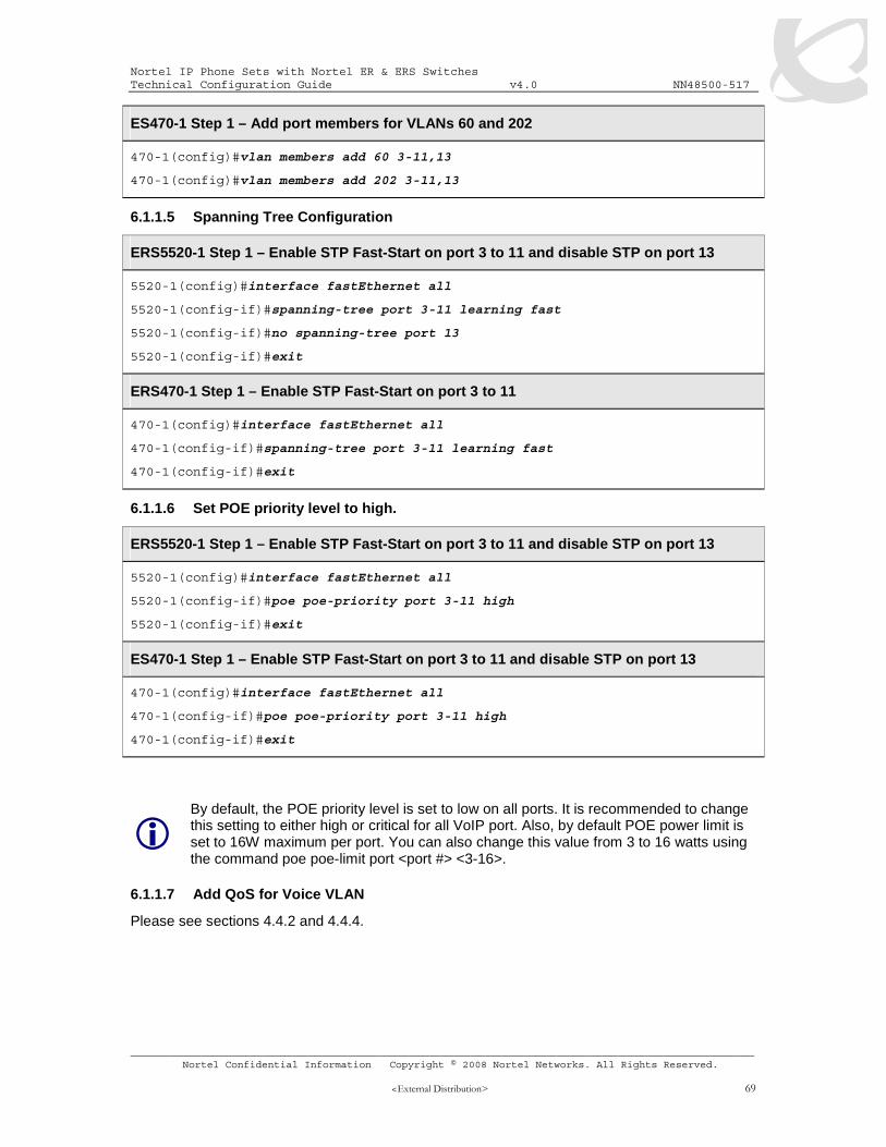
6.1.1 Configuration.............................................................................................................. 68 6.1.1.1 Go to configuration mode................................................................................................68 6.1.1.2 Create VLANs .................................................................................................................68 6.1.1.3 Set the default VLAN PVID on the access port member .................................................68 6.1.1.4 Add VLAN port members ................................................................................................68 6.1.1.5 Spanning Tree Configuration ..........................................................................................69 6.1.1.6 Set POE priority level to high. .........................................................................................69 6.1.1.7 Add QoS for Voice VLAN ................................................................................................69 6.1.1.8 IP and DHCP configuration. ............................................................................................70 6.1.1.9 Enable IP routing and add IP static routes. .....................................................................70 6.1.1.10 Add DHCP relay agents. .................................................................................................70 6.1.1.11 Enable IP Anti-Spoofing ..................................................................................................70
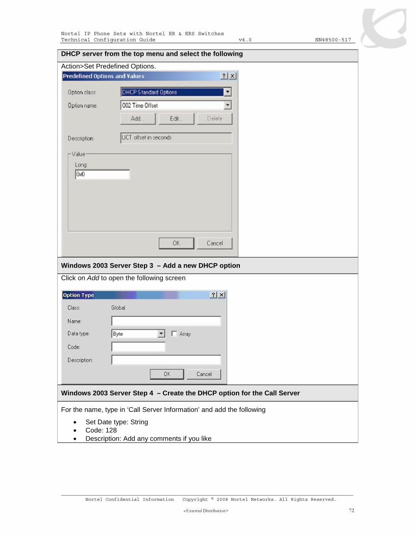
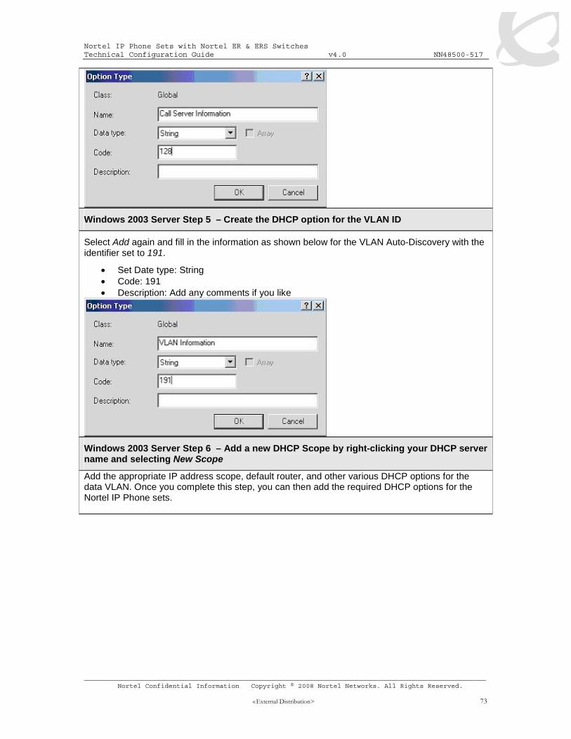
6.1.2 Phone Setup .............................................................................................................. 71 6.1.3 IP Phone 2004 Phase I Setup.................................................................................... 71 6.1.4 DHCP Server Setup................................................................................................... 71
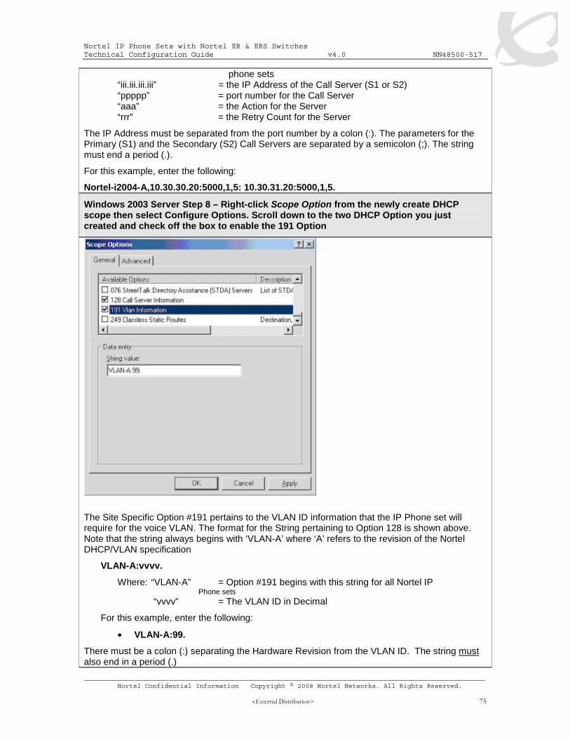
6.2 CONFIGURATION EXAMPLE: AUTO CONFIGURATION USING ETHERNET ROUTING SWITCH 8300 79
6.2.1 Via PPCLI................................................................................................................... 79 6.2.1.1 Enable VLAN tagging on access port members..............................................................79 6.2.1.2 Create Data VLAN 61 .....................................................................................................79 6.2.1.3 Enable Spanning Tree Faststart on access port .............................................................80 6.2.1.4 Create Voice VLAN 220 ..................................................................................................80 6.2.1.5 Create Core VLAN 83 .....................................................................................................80 6.2.1.6 Configure access port membes to untag the default VLAN.............................................80 6.2.1.7 Enable RIP Globally ........................................................................................................80 6.2.1.8 Enable DHCP relay agenets ...........................................................................................81 6.2.1.9 Configure access port member PoE setting to high ........................................................81
Nortel IP Phone Sets with Nortel ER & ERS Switches Technical Configuration Guide v4.0 NN48500-517
6.2.2 Via NNCLI .................................................................................................................. 81 6.2.2.1 Go to configuration mode................................................................................................81 6.2.2.2 Enable VLAN tagging on access port members..............................................................81 6.2.2.3 Create Data VLAN 61 .....................................................................................................81 6.2.2.4 Enable Spanning Tree Faststart on access port .............................................................82 6.2.2.5 Create Voice VLAN 220 ..................................................................................................82 6.2.2.6 Create Core VLAN 83 .....................................................................................................82 6.2.2.7 Configure access port membes to untag the default VLAN.............................................83 6.2.2.8 Enable RIP globally and on each interface .....................................................................83 6.2.2.9 Enable DHCP relay agenets ...........................................................................................83 6.2.2.10 Configure access port member PoE setting to high ........................................................83
6.2.3 Verify Operations ....................................................................................................... 84 6.2.3.1 Using PPCLI....................................................................................................................84 6.2.3.2 Using NNCLI ...................................................................................................................84
7. IP PHONE SET DETECTION................................................................................................ 85
7.1 802.1AB SUPPORT ON NORTEL PRODUCTS ...................................................................... 85 7.2 ADAC SUPPORT ON NORTEL PRODUCTS .......................................................................... 85 7.3 802.1AB ......................................................................................................................... 86
7.3.1 LLDP Configuration on Nortel IP Phone Sets and Switches ..................................... 92 7.3.2 LLDP VLAN Name ..................................................................................................... 93
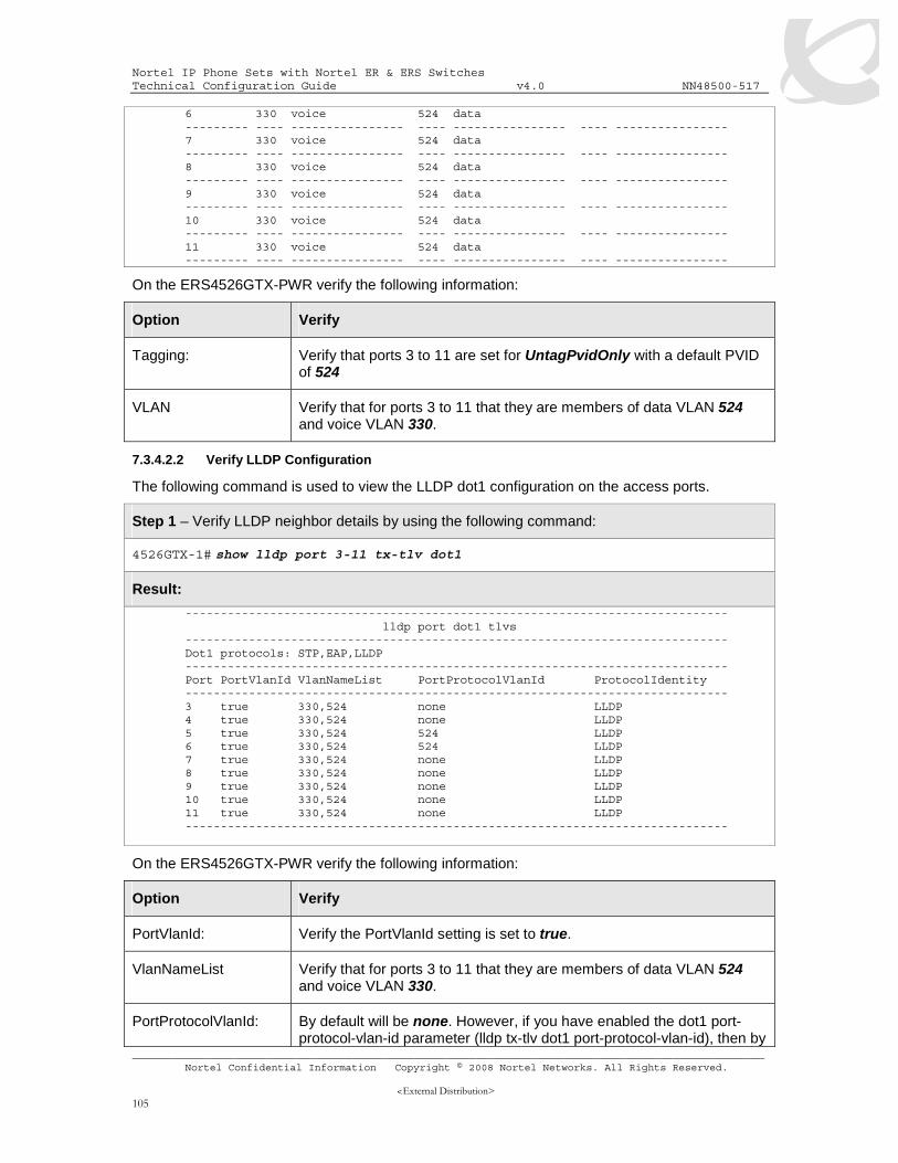
7.3.2.1 LLDP VLAN Name – Nortel IP Phone Configuration.......................................................93 7.3.2.2 LLDP VLAN configuration on the ERS55xx ....................................................................93
7.3.3.4 LLDP-MED configuration on the ERS8300 ...................................................................101 7.3.3.4.1 Enable ADAC at interface level.................................................................................101 7.3.3.4.2 Enable LLDP-MED ...................................................................................................101
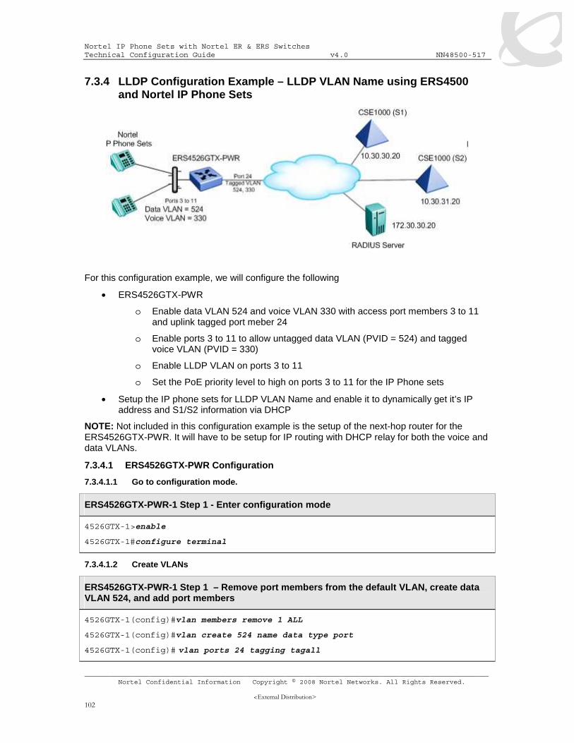
7.3.4 LLDP Configuration Example – LLDP VLAN Name using ERS4500 and Nortel IP Phone Sets........................................................................................................................... 102
7.3.4.1 ERS4526GTX-PWR Configuration................................................................................102 7.3.4.1.1 Go to configuration mode..........................................................................................102 7.3.4.1.2 Create VLANs...........................................................................................................102 7.3.4.1.3 Enable LLDP VLAN Name........................................................................................103 7.3.4.1.4 Configure PoE levels ................................................................................................103 7.3.4.1.5 Add QoS ...................................................................................................................103 7.3.4.1.6 Set Management VLAN ............................................................................................103 7.3.4.1.7 Enable IP Anti Spoofing............................................................................................103 7.3.4.1.8 Enable SNMP Management .....................................................................................104
7.3.4.3 IP Phone Setup .............................................................................................................106 7.4 AUTO DETECTION AND AUTO CONFIGURATION (ADAC) OF NORTEL IP PHONES 107
Nortel IP Phone Sets with Nortel ER & ERS Switches Technical Configuration Guide v4.0 NN48500-517
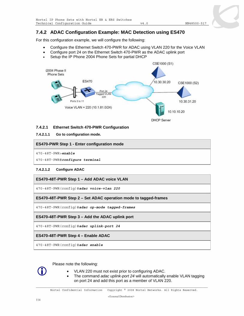
7.4.2 ADAC Configuration Example: MAC Detection using ES470.................................. 114 7.4.2.1 Ethernet Switch 470-PWR Configuration ......................................................................114
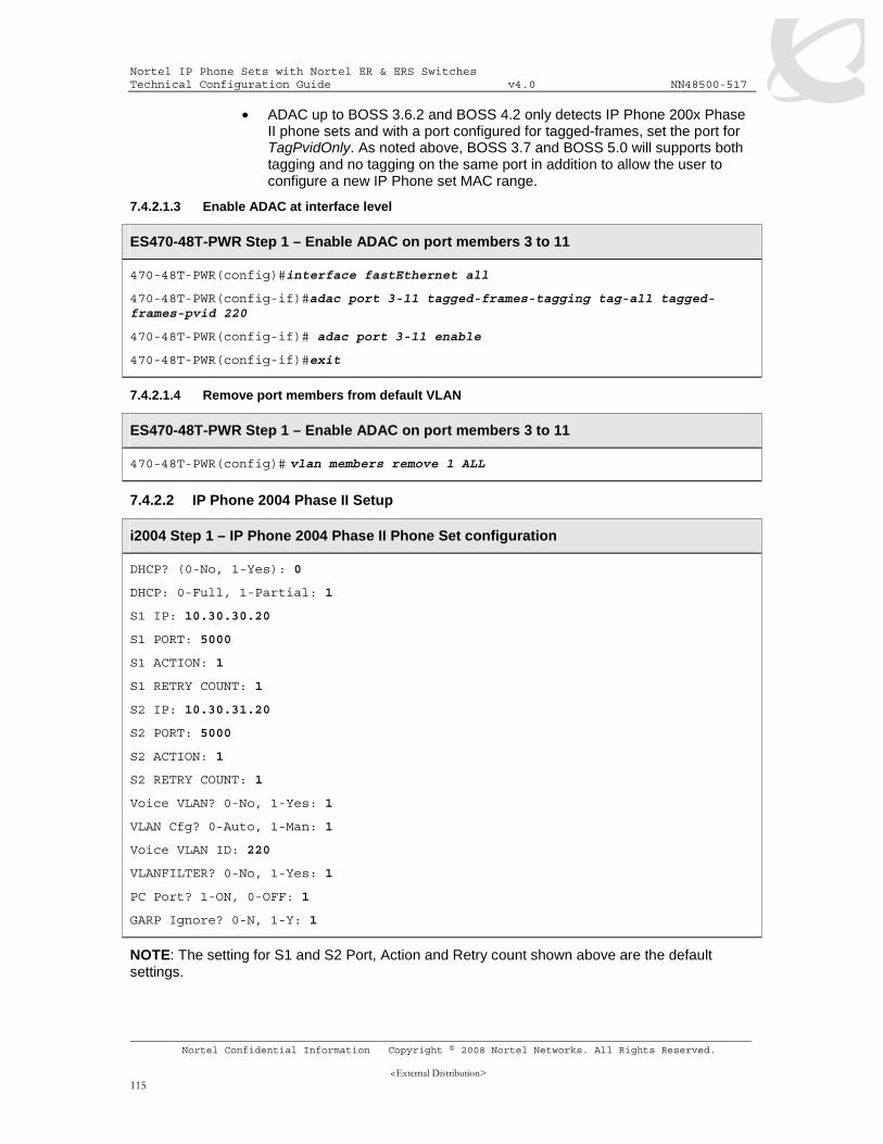
7.4.2.1.1 Go to configuration mode..........................................................................................114 7.4.2.1.2 Configure ADAC .......................................................................................................114 7.4.2.1.3 Enable ADAC at interface level.................................................................................115 7.4.2.1.4 Remove port members from default VLAN ...............................................................115
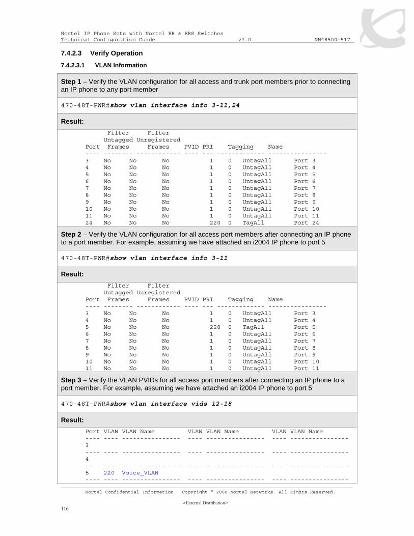
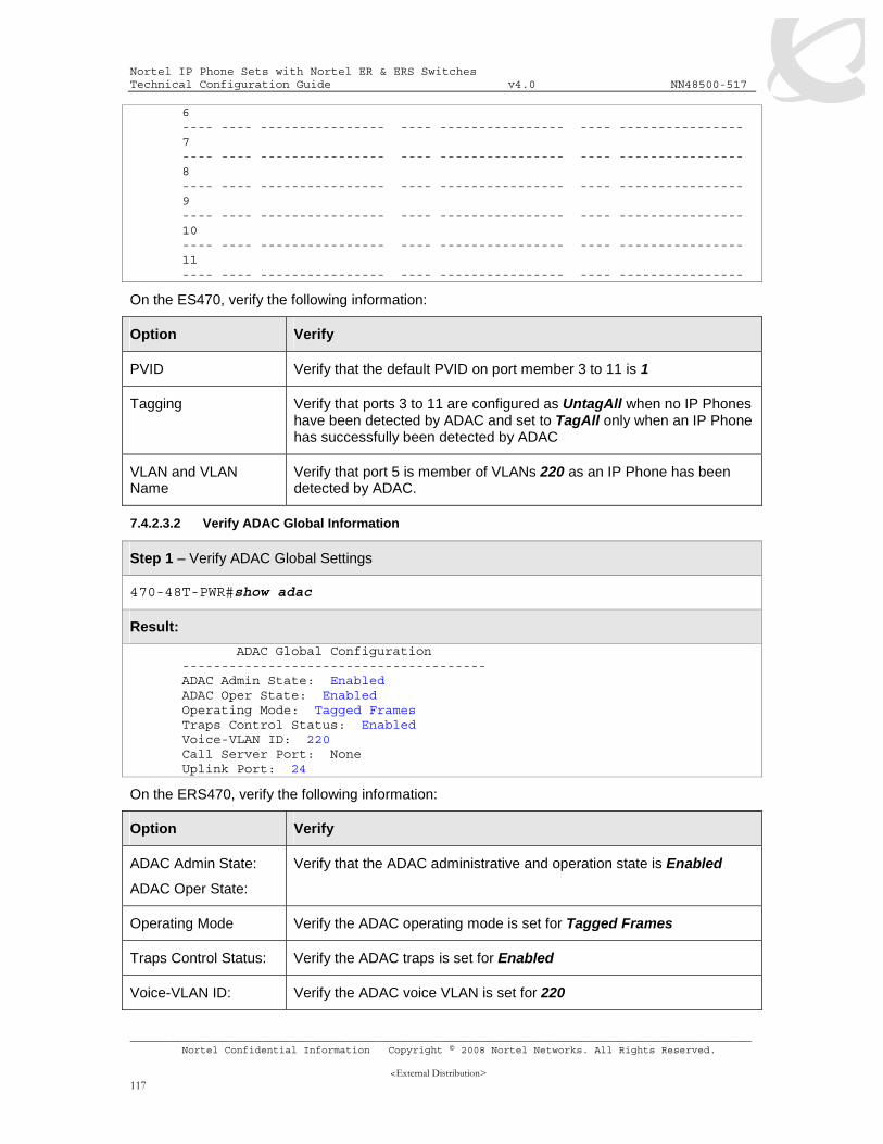
7.4.2.2 IP Phone 2004 Phase II Setup......................................................................................115 7.4.2.3 Verify Operation ............................................................................................................116
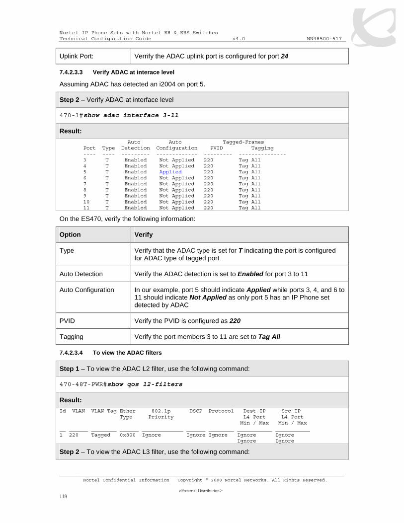
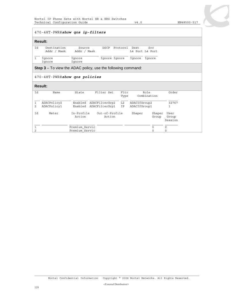
7.4.2.3.1 VLAN Information .....................................................................................................116 7.4.2.3.2 Verify ADAC Global Information ...............................................................................117 7.4.2.3.3 Verify ADAC at interace level....................................................................................118 7.4.2.3.4 To view the ADAC filters ...........................................................................................118
7.4.3 ADAC Configuration – MAC Dectection using ERS5500 and Adding a new MAC address range ...................................................................................................................... 120
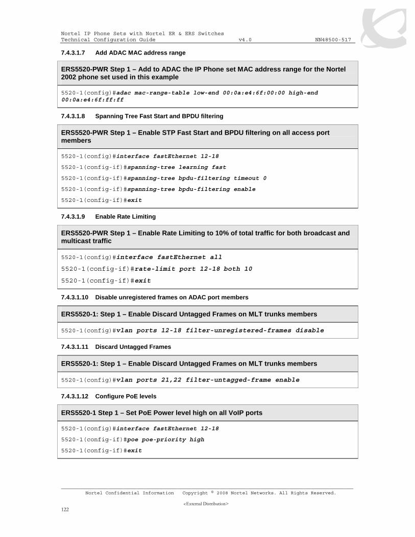
7.4.3.1 Ethernet Switch 5520 Configuration..............................................................................120 7.4.3.1.1 Go to configuration mode..........................................................................................120 7.4.3.1.2 Create MLT...............................................................................................................121 7.4.3.1.3 Configure ADAC .......................................................................................................121 7.4.3.1.4 Remove port members from default VLAN 1 ............................................................121 7.4.3.1.5 Add the data VLAN ...................................................................................................121 7.4.3.1.6 Enable ADAC at interface level.................................................................................121 7.4.3.1.7 Add ADAC MAC address range................................................................................122 7.4.3.1.8 Spanning Tree Fast Start and BPDU filtering ...........................................................122 7.4.3.1.9 Enable Rate Limiting.................................................................................................122 7.4.3.1.10 Disable unregistered frames on ADAC port members ............................................122 7.4.3.1.11 Discard Untagged Frames ......................................................................................122 7.4.3.1.12 Configure PoE levels...............................................................................................122 7.4.3.1.13 Enable IP Spoofing .................................................................................................123
7.4.3.2 IP Phone .......................................................................................................................123 7.4.3.2.1 i2002 and i2004 Setup..............................................................................................123
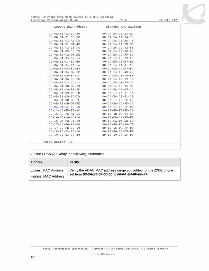
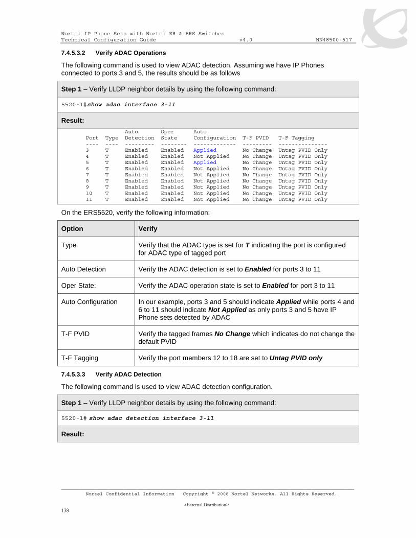
7.4.3.3 Verify configuration .......................................................................................................123 7.4.3.3.1 VLAN Information .....................................................................................................123 7.4.3.3.2 Verify ADAC Global Information ...............................................................................125 7.4.3.3.3 Verify ADAC at interace level....................................................................................126 7.4.3.3.4 Verify ADAC MAC Address table..............................................................................126
7.4.4 ADAC Configuration Example – LLDP Detection using ERS2500 .......................... 128 7.4.4.1 Ethernet Routing Switch 2550T-PWR Configuration.....................................................128
7.4.4.1.1 Go to configuration mode..........................................................................................128 7.4.4.1.2 Remove port members from default VLAN 1 ............................................................128 7.4.4.1.3 Configure ADAC .......................................................................................................128 7.4.4.1.4 Add the data VLAN ...................................................................................................129 7.4.4.1.5 Enable ADAC at interface level.................................................................................129 7.4.4.1.6 Configure PoE levels ................................................................................................129 7.4.4.1.7 .....................................................................................................................................129 7.4.4.1.8 Enable LLDP on ports 3-11.......................................................................................129
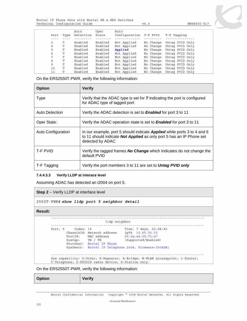
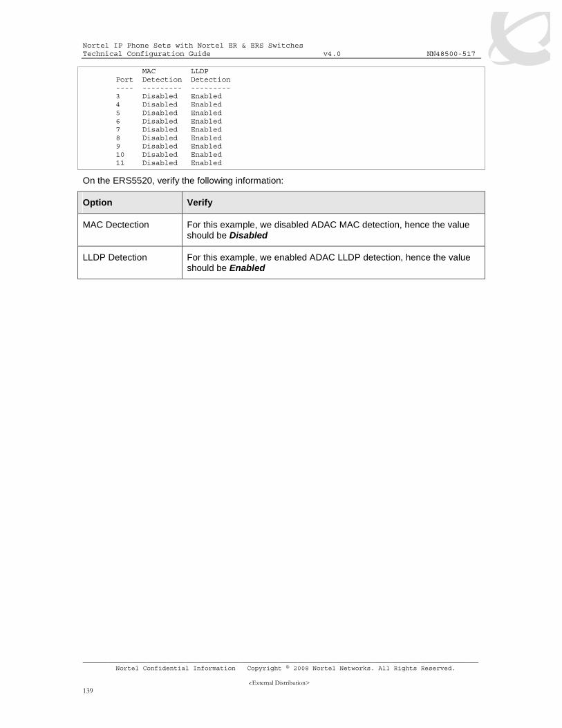
7.4.4.3.1 ADAC Global Information..........................................................................................130 7.4.4.3.2 Verify ADAC at interace level....................................................................................130 7.4.4.3.3 Verify LLDP at interace level.....................................................................................131 7.4.4.3.4 Verify VLAN information............................................................................................132
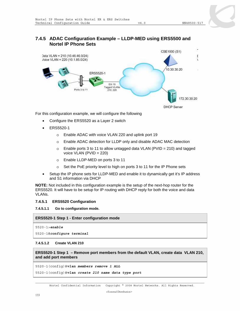
7.4.5 ADAC Configuration Example – LLDP-MED using ERS5500 and Nortel IP Phone Sets 133
7.4.5.1 ERS5520 Configuration ................................................................................................133 7.4.5.1.1 Go to configuration mode..........................................................................................133 7.4.5.1.2 Create VLAN 210......................................................................................................133 7.4.5.1.3 Enable ADAC Globally..............................................................................................134 7.4.5.1.4 Set access port member to untag the default data VLAN 210 ..................................134
Nortel IP Phone Sets with Nortel ER & ERS Switches Technical Configuration Guide v4.0 NN48500-517
7.4.6 Configuration Example – LLDP-MED using ERS8300, and IP Phone 2004 IP Phone Sets 140
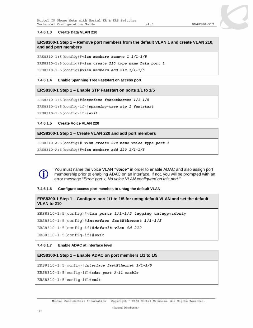
7.4.6.1 ERS8300 Configuration ................................................................................................140 7.4.6.1.1 Go to configuration mode..........................................................................................140 7.4.6.1.2 Enable VLAN tagging on access port members .......................................................140 7.4.6.1.3 Create Data VLAN 210 .............................................................................................141 7.4.6.1.4 Enable Spanning Tree Faststart on access port .......................................................141 7.4.6.1.5 Create Voice VLAN 220............................................................................................141 7.4.6.1.6 Configure access port membes to untag the default VLAN ......................................141 7.4.6.1.7 Enable ADAC at interface level.................................................................................141 7.4.6.1.8 Enable LLDP-MED ...................................................................................................142 7.4.6.1.9 Configure PoE levels ................................................................................................142
7.4.6.3.1 Verify LLDP-MED Operations ...................................................................................142 8. EAPOL SUPPORT .............................................................................................................. 145
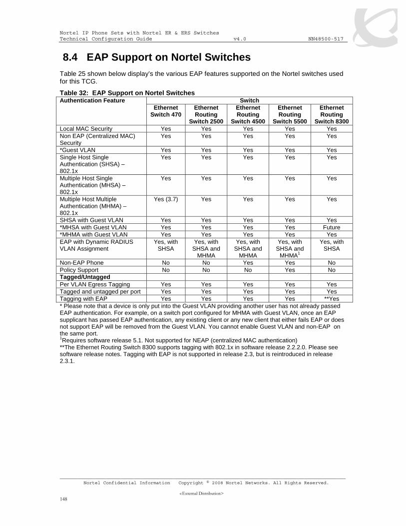
8.1 EAP OVERVIEW ............................................................................................................. 145 8.2 EAP SUPPORT ON NORTEL IP PHONE SETS.................................................................... 147 8.3 EAP AND ADAC ............................................................................................................ 147 8.4 EAP SUPPORT ON NORTEL SWITCHES............................................................................ 148 8.5 EAP CONFIGURATION ON AN ETHERNET SWITCH............................................................. 149 8.6 EAP FEATURE OVERVIEW ON NORTEL SWITCHES ........................................................... 149
9.1 EAP CONFIGURATION EXAMPLE - USING ETHERNET ROUTING SWITCH 5520-PWR WITH EAP SHSA 157
9.1.1 Ethernet Routing Switch 5520-PWR Configuration ................................................. 157 9.1.1.1 Go to configuration mode..............................................................................................157 9.1.1.2 Create VLAN’s ..............................................................................................................157 9.1.1.3 Enable VLAN Tagging...................................................................................................158 9.1.1.4 Add VLAN Port members and default VLAN ID ............................................................158 9.1.1.5 Enable EAP at interface level........................................................................................158 9.1.1.6 Configure Management IP address on switch...............................................................158
Nortel IP Phone Sets with Nortel ER & ERS Switches Technical Configuration Guide v4.0 NN48500-517
9.1.2 IP Phone set configuration....................................................................................... 159 9.1.3 Verify Operations ..................................................................................................... 160
9.1.3.1 Verify EAP Global and Port Configuration.....................................................................160 9.1.3.2 Verify LLDP-MED Configuration....................................................................................160 9.1.3.3 Verify LLDP-MED Operations .......................................................................................161
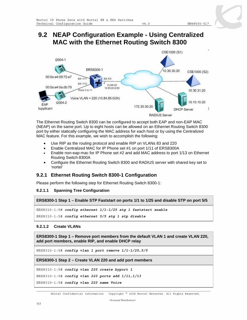
9.2 NEAP CONFIGURATION EXAMPLE - USING CENTRALIZED MAC WITH THE ETHERNET ROUTING SWITCH 8300 ............................................................................................................................ 163
9.2.2 IP Phone Set ............................................................................................................ 165 9.2.3 RADIUS Server Configuration for Centralized MAC - Windows IAS Server ........... 166 9.2.4 DHCP Server Setup................................................................................................. 166
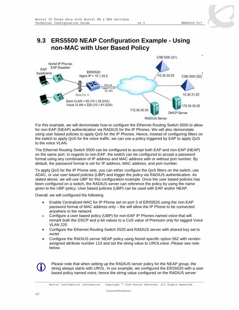
9.3 ERS5500 NEAP CONFIGURATION EXAMPLE - USING NON-MAC WITH USER BASED POLICY 167
9.3.1 Configuration............................................................................................................ 168 9.3.1.1 Go to configuration mode..............................................................................................168 9.3.1.2 Create VLAN’s ..............................................................................................................168 9.3.1.3 Enable VLAN Tagging...................................................................................................168 9.3.1.4 Add VLAN Port members and default VLAN ID ............................................................168 9.3.1.5 Configure Management IP address on switch...............................................................168 9.3.1.6 Configure RADIUS server .............................................................................................169 9.3.1.7 Enable EAP globally......................................................................................................169 9.3.1.8 Enable EAP at interface level........................................................................................169 9.3.1.9 Configure Policy ............................................................................................................170
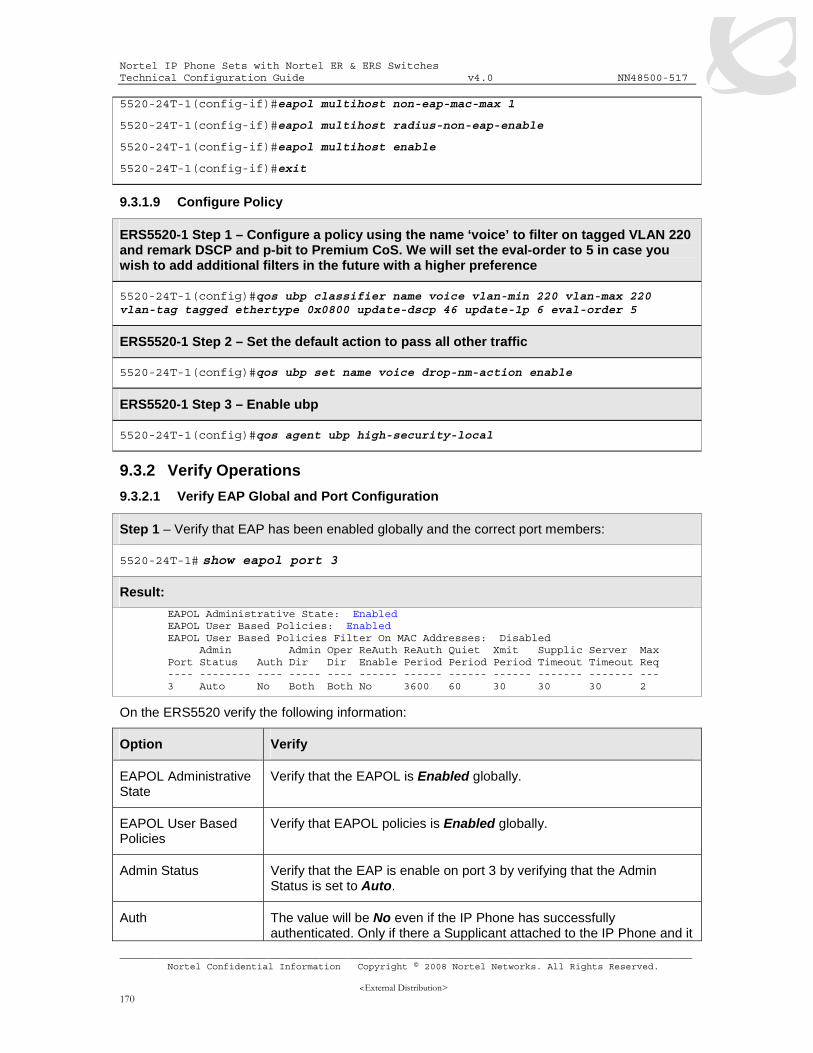
9.3.2 Verify Operations ..................................................................................................... 170 9.3.2.1 Verify EAP Global and Port Configuration.....................................................................170 9.3.2.2 Verify EAP Multihost Configuration ...............................................................................171 9.3.2.3 Verify EAP Multihost Status ..........................................................................................171 9.3.2.4 Verify EAP Policy ..........................................................................................................172 9.3.2.5 Verify EAP Policy upon the NEAP client successfully authenticating............................173 9.3.2.6 View EAP Policy Statistics ............................................................................................173
9.3.3 RADIUS Server – Policy Setup................................................................................ 173 9.4 NON-EAP SUPPORT FOR IP PHONE WITH ADAC LLDP DETECTION FOR QOS – USING THE ETHERNET ROUTING SWITCH 4500............................................................................................. 175
9.4.1.1 Go to configuration mode..............................................................................................175 9.4.1.2 Create Data VLAN ........................................................................................................175 9.4.1.3 Enable ADAC Globally ..................................................................................................176 9.4.1.4 Add VLAN Port members to data VLAN and enable it as the management VLAN .......176 9.4.1.5 Enable ADAC at interface level .....................................................................................176 9.4.1.6 Configure RADIUS server .............................................................................................176 9.4.1.7 Enable EAP globally......................................................................................................176 9.4.1.8 Enable EAP at interface level........................................................................................177 9.4.1.9 Configure Management IP address on switch...............................................................177
9.4.2 Verify Operations ..................................................................................................... 177 9.4.2.1 Verify EAP Global and Port Configuration.....................................................................177 9.4.2.2 Verify EAP Multihost Configuration ...............................................................................178 9.4.2.3 Verify EAP Multihost Port configuration ........................................................................178 9.4.2.4 Verify EAP Multihost Status ..........................................................................................179
Nortel IP Phone Sets with Nortel ER & ERS Switches Technical Configuration Guide v4.0 NN48500-517
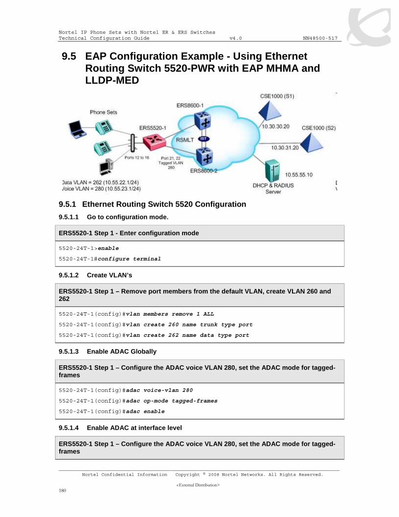
9.5 EAP CONFIGURATION EXAMPLE - USING ETHERNET ROUTING SWITCH 5520-PWR WITH EAP MHMA AND LLDP-MED ............................................................................................................ 180
9.5.1 Ethernet Routing Switch 5520 Configuration........................................................... 180 9.5.1.1 Go to configuration mode..............................................................................................180 9.5.1.2 Create VLAN’s ..............................................................................................................180 9.5.1.3 Enable ADAC Globally ..................................................................................................180 9.5.1.4 Enable ADAC at interface level .....................................................................................180 9.5.1.5 Add access port member and set port to untag the default data VLAN.........................181 9.5.1.6 Add core port member ..................................................................................................181 9.5.1.7 Add MLT........................................................................................................................181 9.5.1.8 Add RADIUS server ......................................................................................................181 9.5.1.9 Enable EAP globally......................................................................................................181 9.5.1.10 Enable EAP at interface level........................................................................................181 9.5.1.11 Enable LLDP-Med on access port members.................................................................182 9.5.1.12 Set PoE level on access port ........................................................................................182 9.5.1.13 Add IP address to VLAN and enable OSPF..................................................................182 9.5.1.14 Enable IP routing and OSPF globlally ...........................................................................183 9.5.1.15 Enable DHCP-Relay agents..........................................................................................183 9.5.1.16 Enable SNMP - Optional ...............................................................................................183
9.5.2 Verify ERS5520 Operations..................................................................................... 183 9.5.3 IP Phone 2004 Phone Set Configuration................................................................. 185 9.5.4 DHCP Server ........................................................................................................... 185
1. Overview This TCG covers standalone Nortel IP Phone sets and how they can be deployed on various Nortel switches. It will cover features on Nortel switches related to VoIP with configuration examples. Overall, topics that will be covered include the following:
Ethernet switch platforms that support PoE:
• Ethernet Switch 470-PWR
• Ethernet Routing Switch 5520-PWR
• Ethernet Routing Switch 4550T-PWR
• Ethernet Routing Switch 4548GT-PWR
• Ethernet Routing Switch 4526T-PWR
• Ethernet Routing Switch 4526GTX-PWR
• Ethernet Routing Switch 2526T-PWR
• Ethernet Routing Switch 2550T-PWR
• Ethernet Routing Switch 8300
VoIP technologies:
• Power over Ethernet (PoE)
• Auto configuration via DHCP for VoIP Phone sets
• Quality over Service (QoS)
• Authentication using EAPoL (802.1x)
• Auto Detection Auto Configuration (ADAC)
o ADAC by itself using either MAC address of IP Phone or 802.1AB (LLDP) for auto-discovery and setting Layer 2 and Layer 3 QoS level.
o On the ERS55xx, ADAC can be used with 802.1AB (LLDP-MED Network Policy) to set the IP Phone set voice VLAN PVID in addition to Layer 2 and Layer 3 QoS values.
Nortel IP Phone Sets with Nortel ER & ERS Switches Technical Configuration Guide v4.0 NN48500-517
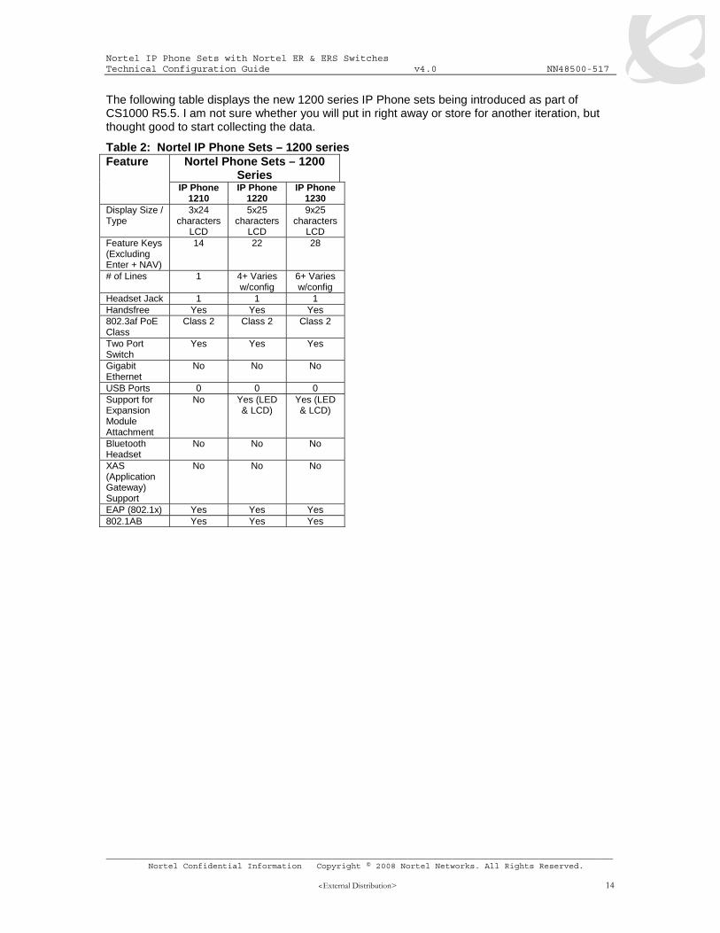
The following table displays the new 1200 series IP Phone sets being introduced as part of CS1000 R5.5. I am not sure whether you will put in right away or store for another iteration, but thought good to start collecting the data.
Table 2: Nortel IP Phone Sets – 1200 series Nortel Phone Sets – 1200
Series Feature
IP Phone 1210
IP Phone 1220
IP Phone 1230
Display Size / Type
3x24 characters
LCD
5x25 characters
LCD
9x25 characters
LCD Feature Keys (Excluding Enter + NAV)
14 22 28
# of Lines 1 4+ Varies w/config
6+ Varies w/config
Headset Jack 1 1 1 Handsfree Yes Yes Yes 802.3af PoE Class
Class 2 Class 2 Class 2
Two Port Switch
Yes Yes Yes
Gigabit Ethernet
No No No
USB Ports 0 0 0 Support for Expansion Module Attachment
No Yes (LED & LCD)
Yes (LED & LCD)
Bluetooth Headset
No No No
XAS (Application Gateway) Support
No No No
EAP (802.1x) Yes Yes Yes 802.1AB Yes Yes Yes
Nortel IP Phone Sets with Nortel ER & ERS Switches Technical Configuration Guide v4.0 NN48500-517
2.1 Configuring an IP Phone 2002 and IP Phone 2004 Phone Set
2.1.1 Accessing the Configuration Menu
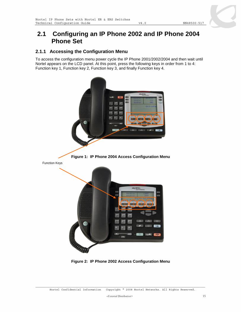
To access the configuration menu power cycle the IP Phone 2001/2002/2004 and then wait until Nortel appears on the LCD panel. At this point, press the following keys in order from 1 to 4: Function key 1, Function key 2, Function key 3, and finally Function key 4.
Figure 1: IP Phone 2004 Access Configuration Menu
Figure 2: IP Phone 2002 Access Configuration Menu
Function Keys
1 2 3 4
1 2 3 4
Nortel IP Phone Sets with Nortel ER & ERS Switches Technical Configuration Guide v4.0 NN48500-517
To power cycle the IP Phone 2004 via the front panel, press the following keys in order from 1 to 9: Mute key, up Navigation key, down Navigation key, up Navigation key, down Navigation key, up Navigation key, Mute, 9, and finally the Goodbye key.
To power cycle the IP Phone 2001 via the front panel, press the following keys in order from 1 to 9: # key, up Navigation key, down Navigation key, up Navigation key, down Navigation key, up Navigation key, #, 9, and finally the Goodbye key.
Figure 3: IP Phone 2004 Power Cycle Phone Set
Figure 4: IP Phone 2002 Power Cycle Phone Set
1, 7
2,4,6
3,5
8
9
1, 7
2,4,6
3,5
8
9
Nortel IP Phone Sets with Nortel ER & ERS Switches Technical Configuration Guide v4.0 NN48500-517
To access the configuration menu, power cycle the IP Phone 2007 and when the Nortel logo appears in the middle of the display, immediately press the following key in sequence: 0, 0, 7, and star (*). If prompted for “Enter Administration Password:”, then press the following keys in sequence: 2, 6, 5, 6, 7, *, 7, 3, 8, OK. Using Navigation Keys scroll down/up to select the configuration options. As an alternative, use the USB port on the back of the IP Phone to use a mouse to scroll and select configuration options.
Figure 5: IP Phone 2007 Phone Set
Nortel IP Phone Sets with Nortel ER & ERS Switches Technical Configuration Guide v4.0 NN48500-517
To access the configuration menu, power cycle the IP Phone 11x0 and when the Nortel logo appears in the middle of the display, immediately press the four feature keys at the bottom of the display in sequence from left to right. If prompted for “Enter Administration Password:”, then press the following keys in sequence: 2, 6, 5, 6, 7, *, 7, 3, 8, Down. Use the Navigation Keys scroll down/up to select configuration options. As an alternative, use the USB port on the back of the IP Phone to use a mouse to scroll and select configuration options.
Figure 6: IP Phone 11xx Series Setup
You can also configure the IP Phone 11x0 IP Phone set by pressing the Services key twice and select option 3 Network Configuration.
Function Keys
1 2 3 4
Navigation Keys
Services keys
Nortel IP Phone Sets with Nortel ER & ERS Switches Technical Configuration Guide v4.0 NN48500-517
To access the configuration menu, power cycle the IP Phone 12x0 and when the Nortel logo appears in the middle of the display, immediately press the four feature keys at the bottom of the display in sequence from left to right. If prompted for “Enter Administration Password:”, then press the following keys in sequence: 2, 6, 5, 6, 7, *, 7, 3, 8, Down. Use the Navigation Keys scroll down/up to select configuration options.
Figure 7: IP Phone 12xx Series Setup
You can also configure the IP Phone 12x0 IP Phone set by pressing the Services key twice and select option 3 Network Configuration.
Function Keys
1 2 3 4
Navigation Keys
Services keys
Nortel IP Phone Sets with Nortel ER & ERS Switches Technical Configuration Guide v4.0 NN48500-517
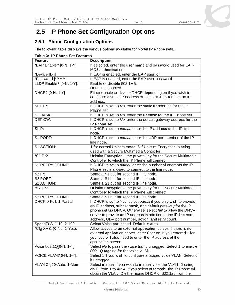
The following table displays the various options available for Nortel IP Phone sets.
Table 3: IP Phone Set Features Feature Description *EAP Enable? [0-N, 1-Y] If selected, enter the user name and password used for EAP-
MD5 authentication. *Device ID:[] If EAP is enabled, enter the EAP user id. *Password:[*******] If EAP is enabled, enter the EAP user password. LLDP Enable? [0-N, 1-Y]: Enable or disable 802.1AB.
Default is enabled DHCP? [0-N, 1-Y] Either enable or disable DHCP depending on if you wish to
configure a static IP address or use DHCP to retrieve an IP address.
SET IP: If DHCP is set to No, enter the static IP address for the IP Phone set.
NETMSK: If DHCP is set to No, enter the IP mask for the IP Phone set. DEF GW: If DHCP is set to No, enter the default gateway address for the
IP Phone set. SI IP: If DHCP is set to partial, enter the IP address of the IP line
node. S1 PORT: If DHCP is set to partial, enter the UDP port number of the IP
line node. S1 ACTION: 1 for normal Unistim mode, 6 if Unistim Encryption is being
used with a Secure Multimedia Controller *S1 PK: Unistim Encryption – the private key for the Secure Multimedia
Controller to which the IP Phone will connect S1 RETRY COUNT: If DHCP is set to partial, enter the number of attempts the IP
Phone set is allowed to connect to the line node. S2 IP: Same a S1 but for second IP line node. S2 PORT: Same a S1 but for second IP line node. S2 ACTION: Same a S1 but for second IP line node. *S2 PK: Unistim Encryption – the private key for the Secure Multimedia
Controller to which the IP Phone will connect S2 RETRY COUNT: Same a S1 but for second IP line node. DHCP:0-Full, 1-Partial If DHCP is set to Yes, select partial if you only wish to provide
an IP address, subnet mask, and default gateway for the IP phone set via DHCP. Otherwise, select full to allow the DHCP server to provide an IP address in addition to the IP line node address, UDP port number, action, and retry count.
Speed[0-A, 1-10, 2-100]: Select Voice port speed. Default is auto. *Cfg XAS: (0-No, 1-Yes): Allow access to an external application server. If there is no
external application server, enter 0 for no. If you entered 1 for yes, you will also need to enter the IP address of the application server.
Voice 802.1Q[0-N, 1-Y] Select No to pass the voice traffic untagged. Select 1 to enable 802.1Q tagging for the voice VLAN.
VOICE VLAN?[0-N, 1-Y]: Select 1 if you wish to configure a tagged voice VLAN. Select 0 if untagged.
VLAN Cfg?0-Auto, 1-Man Select manual if you wish to manually set the VLAN ID using an ID from 1 to 4094. If you select automatic, the IP Phone will obtain the VLAN ID either using DHCP or 802.1ab from the
Nortel IP Phone Sets with Nortel ER & ERS Switches Technical Configuration Guide v4.0 NN48500-517
DHCP? [0-N, 1-Y]: If set to yes, the VLAN ID is configured automatically to the value received from the DHCP server.
LLDP MED? [0-N, 1-Y]: If set to Yes, the VLAN ID is configured automatically using the value received in the LLDP-MED Network Policy TLV. Please note that LLDP must be enabled and auto VLAN configuration must be enabled to prompted for LLDP-MED.
LLDP VLAN? [0-N, 1-Y]: If set to Yes, the VLAN ID is configured automatically to the value received in the VLAN Name TLV. Please note the LLDP and automatic VLAN configuration must be enabled and LLDP MED must be disabled to be prompted for LLDP VLAN.
VLAN: If the VLAN setting is set to Man, enter the voice VLAN ID. *VLAN Filter? 0-No, 1-Yes If set to Yes, all unicast Voice traffic is filtered to the data
device connected to the 3-port switch on the IP Phone set. PC Port? [0-OFF, 1-ON]: Select On if you wish to enable the data port. Speed[0-A, 1-10, 2-100]: Select data port speed. Default is auto. Data 802.1Q[0-N, 1-Y]: Select No to pass the data traffic untagged. Select 1 to enable
802.1Q tagging for the data VLAN and manually set the data VLAN.
PCUntagAll? [0-N, 1-Y]: If set to yes, data VLAN stripping is enabled. If an 802.1Q tag is received, it is stripped from the packet before the packet is forward to the PC port. It makes no difference if the data VLAN is manually configured or not. If set to no, the packet sent to the PC is not modified.
GARP Ignore? (0-No, 1-Yes) Provides GARP Spoof attacks between the IP Phone set and the default gateway from a malicious device.
PSK SRTP? [0-N, 1-Y]: Enables or disabled Secure Real-time Transport Protocol (SRTP) media encryption. Default is 0 for no.
* Denotes IP Phone 2004 Phase II phone, IP Phone 2007, or IP Phone 11xx IP Phone sets only.
2.5.1.1 Full DHCP with Automatic VLAN Assignment
If you select Full DHCP, then the following parameters are retrieved from the DHCP server:
• A valid IP Phone 2004 IP address • A subnet mask • The default Gateway for the IP Phone 2004 on the LAN segment to which it is connected • The S1 node IP address of the IP line node • The S1 Action • The S1 retry count. This is the number of times the IP Phone attempts to connect to the
server • The S2 node IP address of the IP line node • The S2 Action • The S2 retry count • The External Application Server (XAS) IP address
2.5.1.2 Partial DHCP
If you select Partial DHCP, then you must enter the following parameters on the IP Phone set:
• S1 IP • S1 Port • S1 action • S1 retry • S2 IP • S2 Port
Nortel IP Phone Sets with Nortel ER & ERS Switches Technical Configuration Guide v4.0 NN48500-517
Gratuitous Address Resolution Protocol Protection (GARP) prevents the IP Phone set from GARP Spoof attacks on the network. In a GARP Spoof attack, a malicious device on the network takes over an IP address (usually the default gateway) by sending unsolicited (or Gratuitous) ARP messages, thus manipulating the ARP table of the victim’s machine. This allows the malicious device to launch a variety of attacks on the network, resulting in undesired traffic routing. For example, a GARP attack can convince the victim machine that the malicious device is the default gateway. In this scenario, all traffic from the victim’s machine flows through the malicious device.
Extensible Authentication Protocol (EAP) is a general protocol that fulfills the protocol requirements defined by 802.1x. Presently, Nortel IP phone sets only support EAP with MD-5. EAP-PEAP and EAP-TLS are planned for 2Q08.
2.5.1.5 LLDP (802.1AB)
IEEE 802.1AB LLDP is a Layer 2 neighbor discovery protocol. It defines a standard method for Ethernet network devices such as switches, routers and IP Phones to advertise information about themselves to other nodes on the network and store the information they discover. Certain Nortel IP Phone sets can be setup for ether LLDP Vlan Name or LLDP-MED Network Policy but not both at the same time.
2.5.1.6 3-Port Switch
The three-port switch that is internal / external to the IP Phone set is an unmanaged switch. It passes the packets (unmodified) and does not interpret the 802.1Q header. The three-port switch provides priority based on the port (that is, the IP Phone port traffic takes priority over the Ethernet).
Nortel IP Phone Sets with Nortel ER & ERS Switches Technical Configuration Guide v4.0 NN48500-517
The intention of the 802.3af standard is to provide a 10BaseT, 100BaseT, or1000BaseT device with a single interface for the data it requires and the power to process the data. Power is supplied by a Power Sourcing Device (PSE) for one or more Powered Devices (PD). The PSE main function is to only supply power for a PD after it has successfully detected a PD on a link by probing. The PSE can also successfully detect a PD, but then opt to not supply power to the detected PD. The PSE shall only supply power on the same pair as those used for detection.
The cable requirements are defined in ISO/IEC 11801-2000 and EIA/TIA 568A/B (T-568A or B, with most using the A standard) which allows for up to 100 meters of cable.
Power Sourcing Devices (PSE) can deliver power on the data pairs (1+2, 3+6), spare pairs (4+5, 7+8), or either, but only on the pair that the Powered Device (PD) is detected on. Power is not to be supplied to non-powered devices and other PSE’s.
Figure 7: PD and PSE 8-pin Modular Jack Pin’s
Table 4: PSE Pinout Alternatives Conductor Alternative A
In regards to the PD, it must fall into the following characteristics:
• 19k to 26.5k ohm DC resistance • <100nF of capacitance and • a voltage offset of at least 2VDC in the signature characteristics • a current of less than 12uA in the signature characteristics
Anything outside of the characteristics listed above will be considered a non-PD device and the PSE will not supply power. Each port from a PSE should be capable of delivering up to 15W of power. 802.3af also adds a class feature that allows the PSE to limit the power based on the class of the PD detected. Table 4 shown below lists the 802.3af power classes.
1 2 3 4 5 6 7 8 1 2 3 4 5 6 7 8
T-568B T-568A
O/ 0 G/ B B/ G Br/ Br G/ G O/ B B/ O Br/ Br
1 2 3 4 5 6 7 8
Nortel IP Phone Sets with Nortel ER & ERS Switches Technical Configuration Guide v4.0 NN48500-517
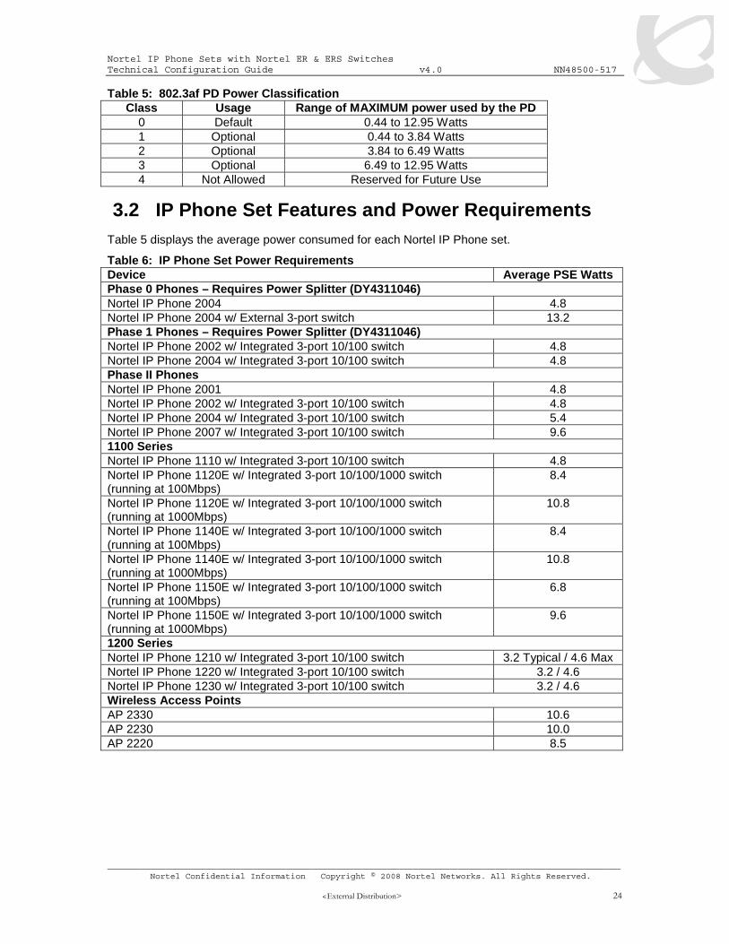
Table 5: 802.3af PD Power Classification Class Usage Range of MAXIMUM power used by the PD
0 Default 0.44 to 12.95 Watts 1 Optional 0.44 to 3.84 Watts 2 Optional 3.84 to 6.49 Watts 3 Optional 6.49 to 12.95 Watts 4 Not Allowed Reserved for Future Use
3.2 IP Phone Set Features and Power Requirements Table 5 displays the average power consumed for each Nortel IP Phone set.
Table 6: IP Phone Set Power Requirements Device Average PSE Watts Phase 0 Phones – Requires Power Splitter (DY4311046) Nortel IP Phone 2004 4.8 Nortel IP Phone 2004 w/ External 3-port switch 13.2 Phase 1 Phones – Requires Power Splitter (DY4311046) Nortel IP Phone 2002 w/ Integrated 3-port 10/100 switch 4.8 Nortel IP Phone 2004 w/ Integrated 3-port 10/100 switch 4.8 Phase II Phones Nortel IP Phone 2001 4.8 Nortel IP Phone 2002 w/ Integrated 3-port 10/100 switch 4.8 Nortel IP Phone 2004 w/ Integrated 3-port 10/100 switch 5.4 Nortel IP Phone 2007 w/ Integrated 3-port 10/100 switch 9.6 1100 Series Nortel IP Phone 1110 w/ Integrated 3-port 10/100 switch 4.8 Nortel IP Phone 1120E w/ Integrated 3-port 10/100/1000 switch (running at 100Mbps)
8.4
Nortel IP Phone 1120E w/ Integrated 3-port 10/100/1000 switch (running at 1000Mbps)
10.8
Nortel IP Phone 1140E w/ Integrated 3-port 10/100/1000 switch (running at 100Mbps)
8.4
Nortel IP Phone 1140E w/ Integrated 3-port 10/100/1000 switch (running at 1000Mbps)
10.8
Nortel IP Phone 1150E w/ Integrated 3-port 10/100/1000 switch (running at 100Mbps)
6.8
Nortel IP Phone 1150E w/ Integrated 3-port 10/100/1000 switch (running at 1000Mbps)
9.6
1200 Series Nortel IP Phone 1210 w/ Integrated 3-port 10/100 switch 3.2 Typical / 4.6 Max Nortel IP Phone 1220 w/ Integrated 3-port 10/100 switch 3.2 / 4.6 Nortel IP Phone 1230 w/ Integrated 3-port 10/100 switch 3.2 / 4.6 Wireless Access Points AP 2330 10.6 AP 2230 10.0 AP 2220 8.5
Nortel IP Phone Sets with Nortel ER & ERS Switches Technical Configuration Guide v4.0 NN48500-517
3.3 Nortel IP Phone Power Splitters Certain vintages of Nortel IP phones are non-802.3af compliant and require a splitter when connecting to an 802.3af compliant switch. This includes the following Nortel IP phones sets: IP Phone 2004 Phase 0, IP Phone 2004 Phase I, and IP Phone 2002 Phase 1. All Phase II versions of the IP Phone 2002 and IP Phone 2004 do not require splitters. The IP Phone 2004 Phase 0 IP Phones can be identified by the label on the back of the phone set and begins with NTEX00. All Phase I IP phone sets are identified with NTDU76/82 for the IP Phone 2002 or IP Phone 2004 IP Phone sets.
The part number for the universal splitter is DY4311046.
3.4 PoE for Nortel PSE Stackable Switches
3.4.1 ES470PWR and ERS5520PWR
Both the Ethernet Switch 470-PWR and Ethernet Routing Switch 5520-PWR can supply power via their own internal power supply and also with the addition on a Redundant Power Supply 15 (RPS 15). The addition of the RPS 15 provides power redundancy and additional PoE power as shown in table 6 below. Overall, both switch families provide the following features:
• IEEE 802.3af standard compliance • Supplies power on pins 1+2, 3+6 • Enable/disable power per port • PoE power limit per port from 3W to 15.4W • Per port current monitoring, power consumption statistics • Port power protection against short or cross connection • Per port power priority to determine which ports will be supplied power first upon power
Max. PoE per port Device PoE Pins Maximum PoE with internal power supply
Maximum power with RPS 15
RPS 15 only AC only w/ RPS 15
ES470-24PWR 1+2, 3+6
370 W 370 W 370 W 15.4 W 15.4 W
ES470-48PWR 1+2, 3+6
370 W 740 W 370 W 7.7 W 15.4 W
ERS5520-24PWR 1+2, 3+6
320 W 370 W 320 W 13.3 W 15.4 W
ERS5520-48PWR 1+2, 3+6
320 W 740 W 320 W 6.7 W 15.4 W
Note: The Redundant Power Supply 15 (RPS 15) chassis can hold up to three power supply modules where each module supporting a single Ethernet Switch 470-PWR or Ethernet Routing Switch 5520-PWR with the appropriate cable. A separate DC-DC converter is not required for these switches as the appropriate RPSU cable plugs directly into the back of the switch.
Nortel IP Phone Sets with Nortel ER & ERS Switches Technical Configuration Guide v4.0 NN48500-517
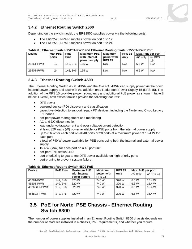
The Ethernet Routing Switch 4550T-PWR and the 4548-GT-PWR can supply power via their own internal power supply and also with the addition on a Redundant Power Supply 15 (RPS 15). The addition of the RPS 15 provides power redundancy and additional PoE power as shown in table 8 below. Overall, both switch families provide the following features:
• DTE power • powered device (PD) discovery and classification • capacitive detection to support legacy PD devices, including the Nortel and Cisco Legacy
IP Phones • per-port power management and monitoring • AC and DC disconnection • load under voltage/current and over voltage/current detection • at least 320 watts (W) power available for PSE ports from the internal power supply • up to 6.6 W for each port on all 48 ports or 20 ports at a maximum power of 15.4 W for
each port • a total of 740 W power available for PSE ports using both the internal and external power
supply • 15.4 W (Max) for each port on a 48 port unit • per-port PoE status LED • port prioritizing to guarantee DTE power available on high-priority ports • port pruning to prevent system failure
Table 9: Ethernet Routing Switch 4500 PoE
Max. PoE per port Device PoE Pins Maximum PoE with internal power supply
Maximum power with RPS 15
RPS 15 only AC only w/ RPS 15
4526T-PWR 1+2, 3+6 320 W 740 W 320 W 6.6 W 15.4 W 4550T-PWR 1+2, 3+6 320 W 740 W 320 W 6.6 W 15.4 W 4526GTX-PWR 1+2, 3+6
320 W 740 W 320 W 6.6 W 15.4 W
4548GT-PWR 1+2, 3+6
320 W 740 W 320 W 6.6 W 15.4 W
3.5 PoE for Nortel PSE Chassis - Ethernet Routing Switch 8300
The number of power supplies installed in an Ethernet Routing Switch 8300 chassis depends on the number of modules installed in a chassis, PoE requirements, and whether you require
Nortel IP Phone Sets with Nortel ER & ERS Switches Technical Configuration Guide v4.0 NN48500-517
optional redundant power. The 8348TX-PWR and 8348GTX-PWR modules support the following features:
• IEEE 802.3af standard compliance • Can supply power on pins 1+2, 3+6 • Supply up to 15.4W per port with a voltage range from 44 to 57 VDC • Enable/disable power per port • PoE power limit per port from 4W to 15.4W • Per port current monitoring, power consumption statistics • Port power protection against short or cross connection • Per port power priority to determine which ports will be supplied power first upon power
cycle Table 10: Recommended Number of 8301AC Power Supplies
Number of 8301AC Power Supplies Chassis Number of modules Required Redundant
configuration
8306 1-6 1 2 1-6 1 2 8310
7-10 2 3
Nortel IP Phone Sets with Nortel ER & ERS Switches Technical Configuration Guide v4.0 NN48500-517
Table 11: ERS8306/8610 Chassis Available System Power Power supply rating
Number of power
supplies
Redundancy Power supply module
PoE per module
Max PoE redundant PoE power reserved
Total
1 No 400 W 200 W 0 W 1140 W 2 Yes 1+1 800 W 400 W 400/200 W 1140 W
100-120VAC 1140W
3 Yes 2+1 1200 W 600 W 400/200 W 2280 W 1 No 800 W 400 W 0 W 1770 W 2 Yes 1+1 1600 W 800 W 800/400 W 1770 W
200-240VAC 1770W
3 Yes 2+1 2400 W 1200 W 800/400 W 3540 W
The Ethernet Routing Switch 8300 can vary the amount of PoE power provided at both the system and module levels. The PoE power at a module level can vary form the default setting of 200 watts to the minimum of 50 watts or the maximum of 800 watts. The maximum PoE power available for allocation determines the maximum number of 8348TX-PWR and 8348GTX-PWR modules that can be supported as shown in table 10 below.
Table 12: Ethernet Routing Switch 8300 Module Power Maximum number of PoE modules supported based on PoE module allocation settings (watts)
Maximum PoE power available for allocation (watts)
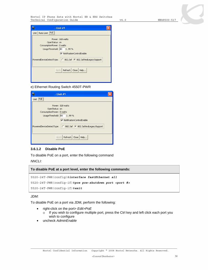
3.6.1 Ethernet Routing Switch 2500, 4500 and Ethernet Switch 470-PWR series
By default, PoE Power Management is enabled by default with all PoE ports power enabled at power up. The following commands apply to the switches listed above.
3.6.1.1 Displaying PoE Status and Statistics
To display the PoE status and statistics, you can use the following commands:
To view the Global PoE status, enter the following command:
5520-24T-PWR#show poe-main-status
5520-24T-PWR#show poe-main-status unit <1-8>
To view the PoE port status, enter the following command:
5520-24T-PWR#show poe-port-status
5520-24T-PWR#show poe-main-status unit <1-8>
To view power used on a PoE port, enter the following command:
By default, all ports with 802.3af Power Class of 0 providing up to 15.4W per port. If you wish, you can limit the power level from 3W to 16W on a per port basis using the following commands:
NNCLI:
To configure the PoE power level, enter the following commands:
5520-24T-PWR(config)#interface fastEthernet all
5520-24T-PWR(config-if)#poe poe-limit port <port #> <3-16>
5520-24T-PWR(config-if)#exit
JDM:
To set the PoE power level on a port via JDM, perform the following:
• right-click on the port> Edit>PoE o If you wish to configure multiple port, press the Ctrl key and left click each port you
wish to configure • Go to PowerLimit and enter a PoE power limit
Uncheck box
Enter a value from 3 to 16 watts
Nortel IP Phone Sets with Nortel ER & ERS Switches Technical Configuration Guide v4.0 NN48500-517
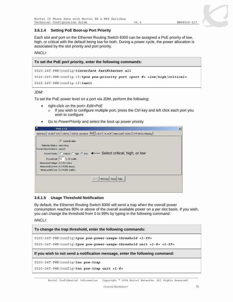
Each slot and port on the Ethernet Routing Switch 8300 can be assigned a PoE priority of low, high, or critical with the default being low for both. During a power cycle, the power allocation is associated by the slot priority and port priority.
NNCLI:
To set the PoE port priority, enter the following commands:
5520-24T-PWR(config)#interface fastEthernet all
5520-24T-PWR(config-if)#poe poe-priority port <port #> <low|high|critical>
5520-24T-PWR(config-if)#exit
JDM:
To set the PoE power level on a port via JDM, perform the following:
• right-click on the port> Edit>PoE o If you wish to configure multiple port, press the Ctrl key and left click each port you
wish to configure
• Go to PowerPriority and select the boot up power priority
3.6.1.5 Usage Threshold Notification
By default, the Ethernet Routing Switch 8300 will send a trap when the overall power consumption reaches 80% or above of the overall available power on a per slot basis. If you wish, you can change the threshold from 0 to 99% by typing in the following command:
NNCLI:
To change the trap threshold, enter the following commands:
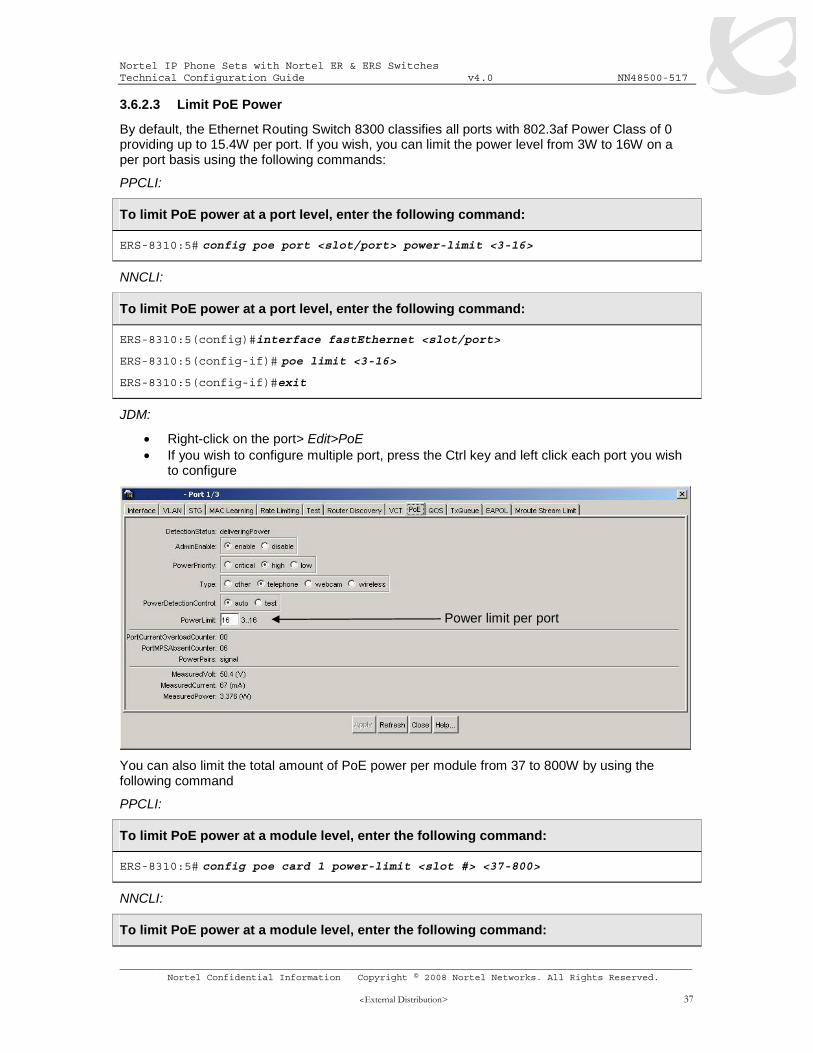
By default, the Ethernet Routing Switch 8300 classifies all ports with 802.3af Power Class of 0 providing up to 15.4W per port. If you wish, you can limit the power level from 3W to 16W on a per port basis using the following commands:
PPCLI:
To limit PoE power at a port level, enter the following command:
ERS-8310:5# config poe port <slot/port> power-limit <3-16>
NNCLI:
To limit PoE power at a port level, enter the following command:
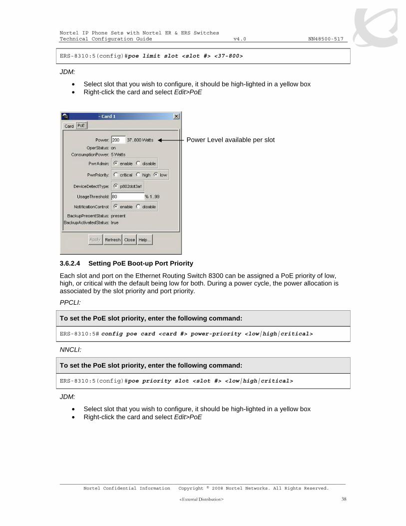
• Select slot that you wish to configure, it should be high-lighted in a yellow box • Right-click the card and select Edit>PoE
3.6.2.4 Setting PoE Boot-up Port Priority
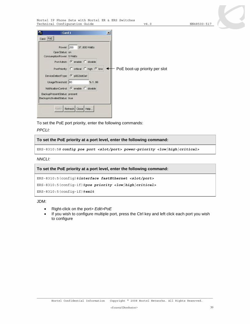
Each slot and port on the Ethernet Routing Switch 8300 can be assigned a PoE priority of low, high, or critical with the default being low for both. During a power cycle, the power allocation is associated by the slot priority and port priority.
PPCLI:
To set the PoE slot priority, enter the following command:
The PSE Power Management Admin Status is enabled by default with power detection set on all ports to auto mode. Power detection can be set for either auto or test where test mode implies the port is in continuous discovery without supplying power. Under normal operation, the Ethernet Routing Switch 8300 will not supply power unless a PD (Powered Device) is requesting power. To change the detection control, enter the following commands.
PPCLI:
To set the PoE detection control, enter the following command:
ERS-8310:5# config poe port <slot/port> power-detection-control <auto|test>
NNCLI:
To set the PoE detection control, enter the following command:
By default, the Ethernet Routing Switch 8300 will send a trap when the overall power consumption reaches 80% or above of the overall available power on a per slot basis. If you wish, you can change the threshold from 0 to 99% by typing in the following command:
PPCLI:
To set the PoE Trap Threshold , enter the following command:
4. QoS By default, Nortel’s IP phones will mark traffic using DiffServ class of Premium. If the voice traffic is tagged, the 802.1p bit will be set to 6 in addition to the DiffServ value set to Explicit Forwarding (EF) with a DSCP value of 0x2e.
By default, most switches that the IP phone set connects to will remark both the p-bit and DSCP value to 0. In the case of the Ethernet Routing Switch or Ethernet Routing Switch 8300, both switches can be enabled to trust the DiffServ value. This is not the case with the Ethernet Switch 470-PWR, and the Ethernet Routing Switch 5520. If ADAC is supported, then this feature can be used to automatically enable DiffServ for the VoIP VLAN. If ADAC is not supported, then a layer 2 filter can be used to filter on the voice VLAN and configured to provide Premium service.
4.1 QoS Mapping Table 11 display’s the default QoS Nortel service class mapping. This is the default mapping used with all the Nortel switches mentioned in the TCG.
Table 13: Nortel QoS Class Mappings DSCP TOS Binary Decimal
4.2 QoS Support on IP Phone Set Table 12 shown below display the default QoS behaviour for each Nortel IP Phone set.
Table 14: Default QoS Marking for IP Phone Sets Phone Set Mark default DSCP to EF for
all voice traffic Mark default Ethernet 802.1p for value of 6 if Voice traffic
is tagged IP Phone 2001 Yes Yes IP Phone 2002 Yes Yes IP Phone 2004 Yes Yes IP Phone 2007 Yes Yes IP Phone 11x0 Series Yes Yes IP Phone 12x0 Series Yes Yes
Nortel IP Phone Sets with Nortel ER & ERS Switches Technical Configuration Guide v4.0 NN48500-517
The 10/100 Mbps Ethernet ports on the Ethernet Switch 470-PWR have four hardware queues as shown in table 13 below. The first queue, strict priority, is always serviced first. The remaining three queues are serviced using a weighted-round-robin (WRR) scheduler.
The cascade port used on the Ethernet Switch 470 has two hardware queues as shown in table 14 below. These two queues are serviced in an absolute priority fashion.
The fixed GBIC slot on the Ethernet Switch 470 supports eight queues as shown in table 15 below. The first queue is serviced in absolute priority fashion while the remaining queues are serviced at the next priority level or service order using a WRR scheduler. Hence, queue id 2 and 3 is serviced prior to queue ids 4 through 8. Both of these have a higher service order.
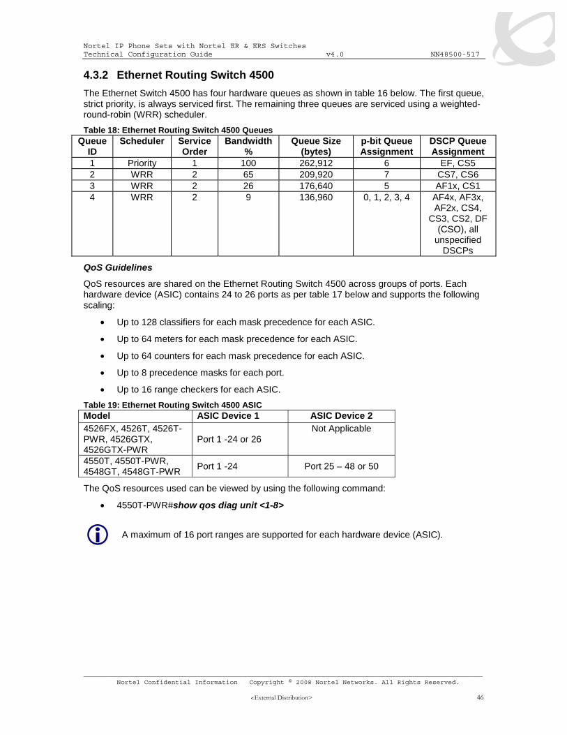
The Ethernet Switch 4500 has four hardware queues as shown in table 16 below. The first queue, strict priority, is always serviced first. The remaining three queues are serviced using a weighted-round-robin (WRR) scheduler.
QoS resources are shared on the Ethernet Routing Switch 4500 across groups of ports. Each hardware device (ASIC) contains 24 to 26 ports as per table 17 below and supports the following scaling:
• Up to 128 classifiers for each mask precedence for each ASIC.
• Up to 64 meters for each mask precedence for each ASIC.
• Up to 64 counters for each mask precedence for each ASIC.
Prior to software release 4.0, the Ethernet Routing Switch 5500 supported a single queue set with eight queues, one absolute queue and seven WRR queues.
With the introduction of software release 4.0, eight different queue sets where made available. Each queue set has different characteristics in regards to number of queues and service weights allowing the user to select a queue set based on the user’s particular needs. With eight queue settings and three resource sharing options, the Ethernet Routing Switch 5500 supports a total of 24 different queues and buffer setting combinations. Prior to making any changes to the egress queue, the buffer resource sharing feature must be enabled.
Resource Sharing
The three (3) possible resource sharing settings in version 4.0 or greater software release are regular, large, and maximum. These settings allow the user to change the amount of buffer which can be allocated or shared to any port. Note that the switch must be rebooted if any changes are made.
Regular 1 port may use up to 16% of the buffers for a group of 12 ports.
Large 1 port may use up to 33% of the buffers for a group of 12 ports.
Maximum 1 port may use 100% of the buffers for a group of 12 ports.
Resource Sharing Commands
• 5520-24T-PWR(config)# qos agent buffer <large | maximum | regular>
The qos agent buffer <regular | large | maximum > command allows the user to specify the level of resource sharing on the switch. This parameter is global and requires a reset to activate a change. This command is in the CLI priv-exec mode.
• 5520-24T-PWR(config)# default qos agent buffer
The default qos agent buffer command sets the switches agent buffer back to a default setting of regular. In order for this command to take affect, a reset of the switch must occur. This command is in the CLI priv-exec mode.
Resource Sharing Recommendations
Nortel recommends you use the default resource-sharing setting of regular. If you change the setting, the resulting performance may increase for some ports, and at times, decrease for other ports.
Generally speaking, smaller buffers achieve lower latency (RTT) but reduce the throughput ability which is better for VoIP etc. and sensible jitter application.
You should use the Maximum resource sharing setting:
• If you are using your 5520 for big file transfers (like backup of servers)
• If you are using (the AppleTalk Filing Protocol) AFP, use large or maximum resource sharing (AFP use a fix windows size set to 65,535K).
Nortel IP Phone Sets with Nortel ER & ERS Switches Technical Configuration Guide v4.0 NN48500-517
You should use the large resource sharing setting:
• If you are using your 5520 for high bandwidth application such as video.
• If you are using large TCP windows for your traffic, use large resource sharing (you can also reduce the TCP windows size on windows operating system - see Microsoft TechNet article 224829).
• If you have 4 or fewer ports connected per group of 12 ports.
You should use the Regular resource sharing setting:
• If you are using your 5520 in a VOIP environment.
• If you have 5 or more ports connected per group of 12 ports.
Egress CoS Queuing
The following charts describe each possible egress CoS queuing setting. The mapping of 802.1p priority to egress CoS queue, dequeuing algorithm, and queue weight is given. Additionally, the memory and maximum number of packets which can be buffered per egress CoS queue and resource sharing settings is shown.
Table 21: Ethernet Routing Switch 5500 Egress CoS Queuing
Setting
Internal Priority
Egress CoS Queue
Dequeuing Algorithm
Weight
Regular Memory/ # of 1518 Byte Packets
Large Memory/ # of 1518 Byte Packets
Max Memory/ # of 1518 Byte Packets
36864B 49152B 131072B 7 1 Strict 100%
24 32 86 36864B 47104B 123392B
6 2 41% 24 31 81 27648B 45056B 115712B
5 3 19% 18 29 76 18432B 43008B 108032B
4 4 13% 12 28 71 18432B 39936B 97792B
3 5 11% 12 26 64 18432B 36864B 85504B
2 6 8% 12 24 56 18432B 33792B 70656B
1 7 5% 12 22 46 18432B 30720B 54272B
8 C
oS
0 8
Weighted Round Robin
3% 12 20 35
Nortel IP Phone Sets with Nortel ER & ERS Switches Technical Configuration Guide v4.0 NN48500-517
The show qos queue-set-assignment command displays in the CLI the 802.1p priority to egress CoS and QoS queue mapping for CoS setting 1-8. This command is in the CLI priv-exec mode.
• 5520-24T-PWR(config)#show qos queue-set
The show qos queue-set command displays the queue set configuration. The display includes the general discipline of the queue, the percent bandwidth (Kbps), and the queues size in bytes. This command is in the CLI priv-exec mode.
• 5520-24T-PWR(config)#qos agent queue set <1-8>
The qos agent queue set <1-8> command sets the egress CoS and QoS queue mode (1-8) in which the switch will operate. This parameter is global and requires a reset to activate a change. This command is in the CLI priv-exec mode.
The qos queue-set-assignment queue-set <1-8> 1p <0-7> queue <1-8> command gives the user the ability to specify the queue to associate an 802.1p priority. This command is in the CLI priv-exec mode.
Nortel IP Phone Sets with Nortel ER & ERS Switches Technical Configuration Guide v4.0 NN48500-517
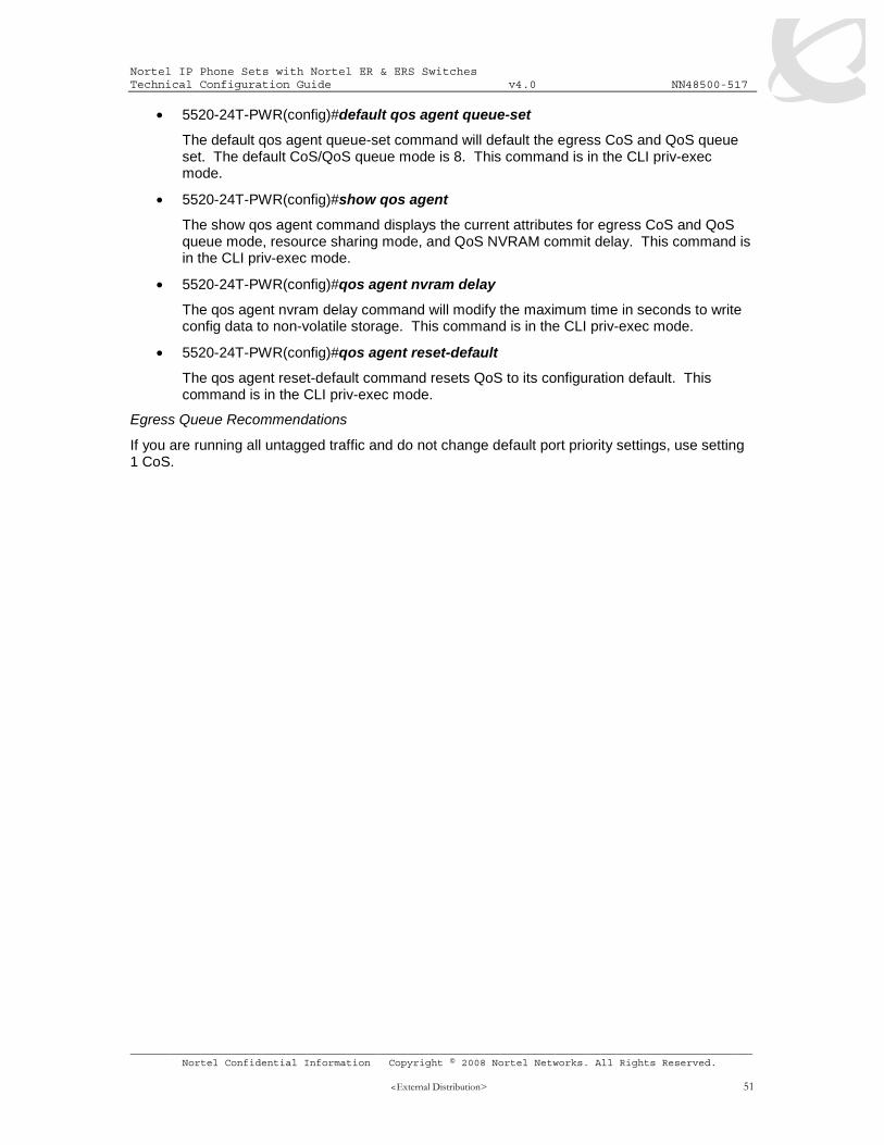
The default qos agent queue-set command will default the egress CoS and QoS queue set. The default CoS/QoS queue mode is 8. This command is in the CLI priv-exec mode.
• 5520-24T-PWR(config)#show qos agent
The show qos agent command displays the current attributes for egress CoS and QoS queue mode, resource sharing mode, and QoS NVRAM commit delay. This command is in the CLI priv-exec mode.
• 5520-24T-PWR(config)#qos agent nvram delay
The qos agent nvram delay command will modify the maximum time in seconds to write config data to non-volatile storage. This command is in the CLI priv-exec mode.
• 5520-24T-PWR(config)#qos agent reset-default
The qos agent reset-default command resets QoS to its configuration default. This command is in the CLI priv-exec mode.
Egress Queue Recommendations
If you are running all untagged traffic and do not change default port priority settings, use setting 1 CoS.
Nortel IP Phone Sets with Nortel ER & ERS Switches Technical Configuration Guide v4.0 NN48500-517
Each Ethernet port on the Ethernet Routing Switch 8300 supports eight hardware queues as shown in table 18 below. Each of the eight queues is mapped to one of the eight QoS levels while each queue can be configured using one of three scheduling arbitration groups, i.e. strict priority, DWRR0, and DWRR1 where strict always have the highest precedence followed by DWRR1 and then DWRR0. This allows you to have the flexibility, if you wish to change all eight queues to Strict Priority. In addition, each per queue shaping can be enabled for shaping with a minimum shaping rate of 1 Mbps
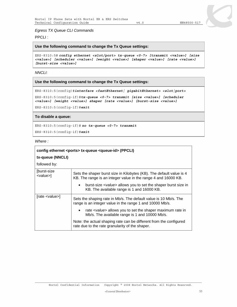
Specifies the proportion (in units of 256 bytes) of bandwidth assigned to this queue relative to the other queues in the arbitration group. The range is from 1 to 256. Nortel recommends that the minimum weight (weight * 256) be greater than the port MTU.
Nortel IP Phone Sets with Nortel ER & ERS Switches Technical Configuration Guide v4.0 NN48500-517
[scheduler <value>] Sets the scheduling Arbitration group.
value allows you to set one of the three following scheduling arbitration groups:
• Strict priority - This Arbitration Group is served first, where the priority goes from the highest queue index to the lowest.
• DWRR1 - This Arbitration Group may transmit packets when there is no traffic from the SP Arbitration Group.
• DWRR0 - This Arbitration Group may transmit packets when there is no traffic from the DWRR Group 1.
Note: Within each DWRR Arbitration Group, each queue is guaranteed its proportional minimal bandwidth according to its configured weight.
shaper <value>] (PPCLI only) Enables or disables transmission of shaper on the port.
• shaper <value> allows you to enable or disable the feature.
[size <value>] Specifies the number of packet descriptors allocated for the queue.
• size <value> sets the number of descriptors in resolution of 16 {16..384}
[transmit <value>] (PPCLI only) Enables or disables transmission on the queue.
• transmit <value> enables or disables the feature
[weight <value>] Specifies the proportion (in units of 256 bytes) of bandwidth
assigned to this queue relative to the other queues in the arbitration group.
• value is an integer value in the range 1 and 256, which represents units of bandwidth in the DWRR. The default value is 8 units, which is 8 * 256 (2048).
Note: Nortel recommends that the minimum weight (N * 256) be greater than the port MTU.
4.4 Configuring QoS on a Nortel Switch The easiest method to enable QoS on an Ethernet Switch or Ethernet Routing Switch is simply to create a layer 2 filter to filter only on the voice VLAN and configure the filter to provide DiffServ Premium service or configure the filter to trust the DiffServ Markings from the IP Phone set.
For more details on configuring filters on the Ethernet Routing Switch 5500, please go to www.nortel.com/support, select documentation for Ethernet Routing Switch 5520, select filter and sort and select Operational Configuration, and finally, select the document titled BS5510 Technical Configuration Guide for CoS.
For more details on configuring filters and QoS on the Ethernet Routing Switch 8300, please go to www.nortel.com/support, select documentation for Ethernet Routing Switch 8300, select filter and sort and select Operational Configuration, and finally, select any of following documents:
• PP8300 Technical Configuration Guide for QOS (NNCLI or CLI) • PP8300 Technical Configuration Guide for Filters (NNCLI or CLI)
Nortel IP Phone Sets with Nortel ER & ERS Switches Technical Configuration Guide v4.0 NN48500-517
If the voice VLAN is untagged, you can configure the switch port members as either trusted or unrestricted. If you wish to support both voice and data on the same port, the switch can be configured for either untrusted or unrestricted. If you choice to use untrusted, you will have have to configure an ACL or Policy to match the voice VLAN and remark the traffic to Premium CoS. If you choice to use unrestricted, you will have to configure a Policy to match the voice VLAN with an in-profile action of Null. This will pass the QoS markings from the IP Phone set as-is. In either case, the out-of-profile action should be set to remark the data traffic to Standard CoS.
Table 23: QoS Interface Class Options
Type of filter Action Trusted Untrusted Unrestricted
ERS4500, ERS5500, ES470 DSCP Does not
change • Tagged--Updates to 0
(Standard) • Untagged--Updates
using mapping table and port’s default value
Does not change
IPv4 filter criteria or Layer 2 filter criteria matching IPv4
IEEE 802.1p
Updates based on DSCP mapping table value
Updates based on DSCP mapping table value ES470:
• Tagged—Updates to 0 • Untagged--Updates to
port’s default value
Does not change
On the ERS4500, either Policies or ACL’s can be used to configure QoS.
4.4.2 Policy Configuration Option: Configuring L2 QoS on a Ethernet Routing Switch 5500 or 4500 using Layer 2 element, classifiers and policy for Tagged Voice VLAN
The following demonstrates two methods used to configure a simple layer 2 filter depending on if the port is configured as untrusted or unrestricted. In our example VLAN 220 will be used for the Voice VLAN. The procedure is to a) configure a layer 2 element to match the Voice VLAN, b) add a classifier to match the layer 2 element, and finally c) add a policy.
4.4.2.1 Configure a layer 2 element.
When configuring a layer 2 element, enter the voice VLAN value and set the EtherType to 0x0800. An EtherType value of 0x0800 signifies IP traffic. For example, assuming the voice VLAN is 220, enter the command as shown below. Assuming if no previous layer 2 elements have been configured, start with element ID = 1.
In reference to the ERS4500 only, either elements or ACL’s can be used. If you use ACL’s, you do not have to configure a classifier or classifer blocks. Please see next section if you wish to enable ACLs on the ERS4500.
ERS4500/5500: Step 1 – Create a new layer 2 element, assign Voice VLAN and set the EtherType to 0x0800
Nortel IP Phone Sets with Nortel ER & ERS Switches Technical Configuration Guide v4.0 NN48500-517
Next, configure a classifier element and add the layer 2 element configured above. Again, assuming no previous classifiers have been configured, start with classifier ID = 1.
ERS4500/5500: Step 1 – Add layer 2 element to a classifier by starting with classifer id 1 and adding layer 2 element id 1 from step above
In reference to the ERS4500 only, if you selected to configure an ACL, this step is not required. An element is automatically created which can be viewed by using the following command
• 4550T-PWR(config)#show qos classifier
Id Classifier Classifier Criteria Criteria Session Storage Name Set Id Type Id Id Type _____ ________________ __________ ________ ________ __________ _________ 55001 UntrustedClfrs1 55001 L2 55001 0 Other 55002 UntrustedClfrs2 55002 L2 55002 0 Other 55004 vlan_fil 55004 L2 55004 0 Other
4.4.2.3 Add Policy
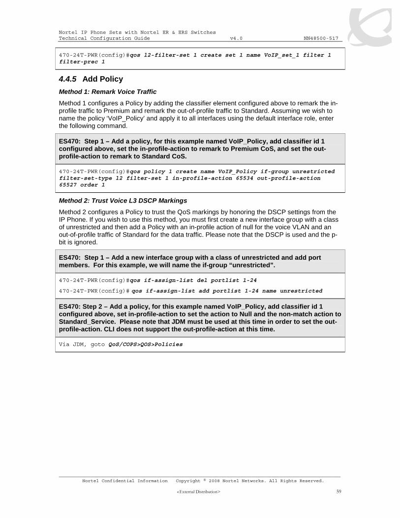
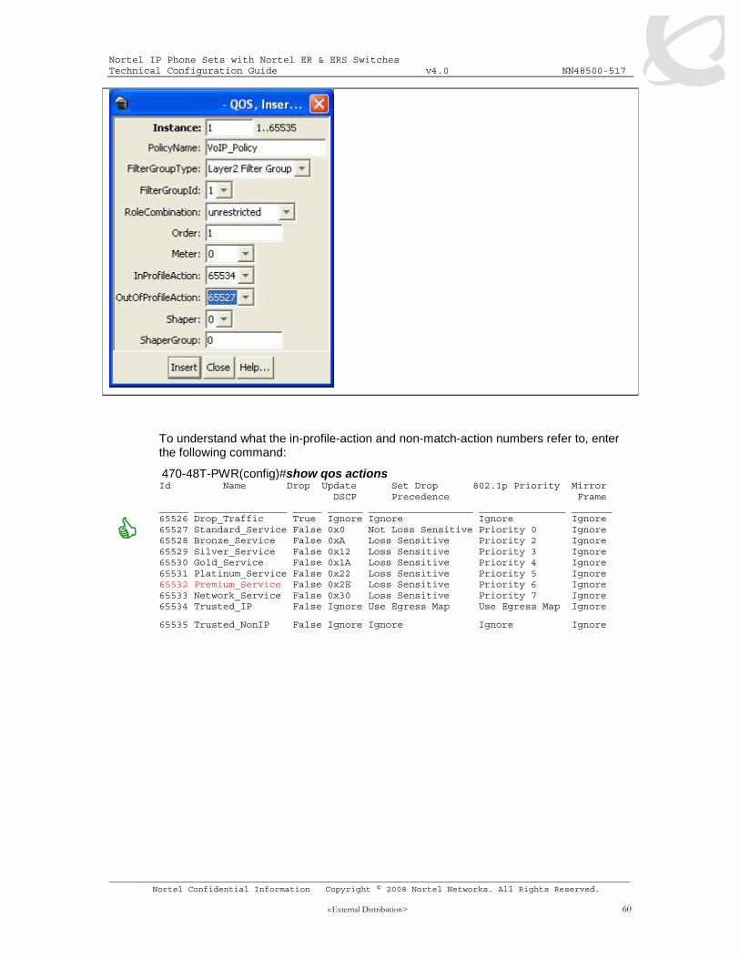
Method 1: Remark Voice Traffic
Method 1 is to configure a Policy and add the classifier element configured above to remark the in-profile traffic to Premium by matching the voice VLAN and setting the out-of-profile traffic to QoS level of Standard. The end result is all the voice traffic will be remarked to Premium CoS while the out-of-provile data traffic will be remarked to Standard CoS. Assuming we wish to name the policy ‘VoIP_Policy’ and apply it to all interfaces using the default interface role, enter the following commands.
ERS5500: Step 1 – Add a policy, for this example named VoIP_Policy, add classifier id 1 configured above, set in-profile-action to remark to Premium CoS, and set the non-match action to remark to Standard CoS.
ERS4500: Step 1 – Add a policy, for this example named VoIP_Policy, add classifier id 1 configured above, set in-profile-action to remark to Premium CoS, and set the non-match action to remark to Standard CoS.
You can also apply the policy to an individual port member instead of an interface role with multiple port members. For example, assuming only wish to apply the policy to port
Nortel IP Phone Sets with Nortel ER & ERS Switches Technical Configuration Guide v4.0 NN48500-517
• 5520-24T-PWR(config)#qos policy 1 name VoIP_Policy port 12 clfr-type classifier clfr-id 1 in-profile-action 7 non-match-action 2
Method 2: Trust Voice Markings
Method 2 is to configure a Policy to trust the QoS markings from the IP Phone by honoring the QoS settings from the IP Phone. If you wish to use this method, you must first create a new interface group with a class of unrestricted and then add a Policy to with an in-profile action of null for the voice VLAN and out-of-profile action of Standard. By using a null action for the voice traffic, the switch will pass QoS markings from the IP Phone sets as-is while remarking the data traffic to Standard CoS.
ERS5500: Step 1 – Add a new interface group with a class of unrestricted and add port members. For this example, we will name the if-group “unrestricted”.
5520-24T-PWR(config)#qos if-group name unrestricted class unrestricted
5520-24T-1(config)#qos if-assign port 1-24 name unrestricted
ERS5500: Step 2 – Add a policy, for this example named VoIP_Policy, add classifier id 1 configured above, set the in-profile-action action to Null and the non-match action to Standard_Service.
Note that you can use either ID’s or names for the classifiers and policy actions. Method 1 shows and example using ID’s while method 2 shows names.
To understand what the in-profile-action and non-match-action refer to, enter the following command:
5520-24T-PWR#show qos action Id Name Drop Update 802.1p Set Drop Extension Storage DSCP Priority Precedence Type _____ ________________ _____ ______ ____________ ___________ _________ _______ 1 Drop_Traffic Yes Ignore Ignore High Drop ReadOnly 2 Standard_Service No 0x0 Priority 0 High Drop ReadOnly 3 Bronze_Service No 0xA Priority 2 Low Drop ReadOnly 4 Silver_Service No 0x12 Priority 3 Low Drop ReadOnly 5 Gold_Service No 0x1A Priority 4 Low Drop ReadOnly 6 Platinum_Service No 0x22 Priority 5 Low Drop ReadOnly 7 Premium_Service No 0x2E Priority 6 Low Drop ReadOnly 8 Network_Service No 0x30 Priority 7 Low Drop ReadOnly 9 Null_Action No Ignore Ignore Low Drop ReadOnly 55001 UntrustedClfrs1 DPass Ing 1p Ignore Low Drop Other 55002 UntrustedClfrs2 DPass 0x0 Priority 0 High Drop Other
Nortel IP Phone Sets with Nortel ER & ERS Switches Technical Configuration Guide v4.0 NN48500-517
Please note that the DSCP value is entered as a decimal value. The decimal value for CoS level Premium is 46. You should also update the p-bit in case the Voice VLAN port members are set to tagged. Please refer to table 11.
4.4.3.2 Assign ACL to port members
ERS4500: Step 1 – Assign the ACL vlan_fil to the appropriate port members; for example, port member 14 and 16:
4550T-PWR(config)# qos acl-assign port 14,16 acl-type l2 name vlan_fil
4.4.4 Configuring L2 QoS on an Ethernet Switch 470 for Tagged Voice VLAN
The following demonstrates two methods used to configure a simple layer 2 filter depending on if the port is configured as untrusted or unrestricted. In our example VLAN 220 will be used for the Voice VLAN. The procedure is to a) configure a layer 2 element to match the Voice VLAN, b) add a classifier to match the layer 2 element, and finally c) add a policy.
4.4.4.1 Configure a layer 2 element.
When configuring a layer 2 element, enter the voice VLAN value and set the EtherType to 0x0800. An EtherType value of 0x0800 signifies IP traffic. For example, assuming the voice VLAN is 220, enter the command as shown below. Assuming if no previous layer 2 elements have been configured, start with element ID = 1.
ES470: Step 1 – Create a new layer 2 element, assign Voice VLAN and set the EtherType to 0x0800
Next, configure a classifier element and add the layer 2 element configured above. Again, assuming no previous classifiers have been configured, start with classifier ID = 1.
ES470: Step 1 – Add layer 2 element to a classifier by starting with classifer id 1 and adding layer 2 element id 1 from step above
Nortel IP Phone Sets with Nortel ER & ERS Switches Technical Configuration Guide v4.0 NN48500-517
470-24T-PWR(config)#qos l2-filter-set 1 create set 1 name VoIP_set_1 filter 1 filter-prec 1
4.4.5 Add Policy
Method 1: Remark Voice Traffic
Method 1 configures a Policy by adding the classifier element configured above to remark the in-profile traffic to Premium and remark the out-of-profile traffic to Standard. Assuming we wish to name the policy ‘VoIP_Policy’ and apply it to all interfaces using the default interface role, enter the following command.
ES470: Step 1 – Add a policy, for this example named VoIP_Policy, add classifier id 1 configured above, set the in-profile-action to remark to Premium CoS, and set the out-profile-action to remark to Standard CoS.
470-24T-PWR(config)#qos policy 1 create name VoIP_Policy if-group unrestricted filter-set-type l2 filter-set 1 in-profile-action 65534 out-profile-action 65527 order 1
Method 2: Trust Voice L3 DSCP Markings
Method 2 configures a Policy to trust the QoS markings by honoring the DSCP settings from the IP Phone. If you wish to use this method, you must first create a new interface group with a class of unrestricted and then add a Policy with an in-profile action of null for the voice VLAN and an out-of-profile traffic of Standard for the data traffic. Please note that the DSCP is used and the p-bit is ignored.
ES470: Step 1 – Add a new interface group with a class of unrestricted and add port members. For this example, we will name the if-group “unrestricted”.
470-24T-PWR(config)#qos if-assign-list del portlist 1-24
470-24T-PWR(config)# qos if-assign-list add portlist 1-24 name unrestricted
ES470: Step 2 – Add a policy, for this example named VoIP_Policy, add classifier id 1 configured above, set in-profile-action to set the action to Null and the non-match action to Standard_Service. Please note that JDM must be used at this time in order to set the out-profile-action. CLI does not support the out-profile-action at this time.
Via JDM, goto QoS/COPS>QOS>Policies
Nortel IP Phone Sets with Nortel ER & ERS Switches Technical Configuration Guide v4.0 NN48500-517
4.4.6 Configure L2 QoS on a Ethernet Routing Switch 8300
By default, the Ethernet Routing Switch 8300 trusts the 802.1p value with a default behavior as shown in table 22 below. Providing the VoIP VLAN is tagged, no additional configuration steps are required.
Table 24: Default QOS Behavior for the Ethernet Routing Switch 8300 802.1p DSCP Traffic Type
Behavior Queue Behavior Queue Bridged, i.e. VLAN without IP address
Tagged Passed as-is As per traffic class and
queue mapping
Passed as-is As per p-bit
Untagged N/A N/A Passed as-is Queue 1 Routed, i.e. VLAN with IP address assigned
Tagged Passed as-is As per traffic class and
queue mapping
Passed as-is As per p-bit
Untagged N/A N/A Passed as-is Queue 1
If the IP Phone set voice VLAN is not tagged, you could set up a filter to trust the DSCP value, classify traffic based on VLAN value, or remark the DSCP value.
4.4.6.1 Trust DSCP Value Configuration
To setup a filter to trust the DSCP value, please enter the following commands
PPCLI:
ERS8300: Step 1 – Create a new ACL with an action to trust the DSCP value. Assuming no ACLs have been configured, start with ACL 1
For IP subnet and Protocol-based VLANs you can set up a default traffic class level based on the VLAN id. The VLAN QoS level can be assigned a value from 0 (lowest) to 7 (highest) with a default setting of 1. Note that you cannot apply a VLAN QoS level to port-based VLANs. For example, assuming the VoIP VLAN is 220 with port members 1/3 to 1/11, enter the following commands:
PPCLI:
ERS8300: Step 1 – Create VLAN 220 and add port members
Assuming we wish to filter on the VoIP VLAN with the MAC address range belonging to the IP Phone sets and set the DiffServ value to EF (0x2e). This can be accomplished by using the commands shown below.
Nortel IP Phone Sets with Nortel ER & ERS Switches Technical Configuration Guide v4.0 NN48500-517
ERS8300: Step 1 – Create a new ACT to allow ACL filtering on MAC addresses
ERS8300:5# filter act 2 ethernet ip src-mac ff:ff:ff:ff:ff:ff dst-mac ff:ff:ff:ff:ff:ff vlan-mask 0x0fff name "act_2_ip-mac"
ERS8300: Step 2 – Enable the ACT to also allow ACL filtering on the DSCP value
ERS8300:5# config filter act 2 ip ip 0.0.0.0 tos 0xff
NNCLI:
ERS8300: Step 1 – Create a new ACT to allow ACL filtering on MAC addresses
ERS8300:5(config)#filter act 2 ethernet ip src-mask ff:ff:ff:ff:ff:ff dst-mask ff:ff:ff:ff:ff:ff vlan-mask 0x0fff name act-2-ip-mac
ERS8300: Step 2 – Enable the ACT to also allow ACL filtering on the DSCP value
ERS8300:5(config)#filter act 2 ip tos 0xff
4.4.8.2 Create an ACL
For our example, we will assume the voice VLAN is 220 while the MAC address range is from 00:0a:e4:00:00:00 to 00:0a:e4:ff:ff:ff.
PPCLI:
ERS8300: Step 1 – Add ACL 1 using the name ACL-1_VoIP, add ACT 2 created above, and enable the ACL to filter on the specified MAC address in VLAN 220 to remark traffic using Premium CoS and remark all other traffic as Standard CoS
ERS8300: Step 1 – Add ACL 1 using the name ACL-1_VoIP, add ACT 2 created above, and enable the ACL to filter on the specified MAC address in VLAN 220 to remark traffic using Premium CoS and remark all other traffic as Standard CoS
ERS8300:5(config)#filter acl 1 ip acl-name ACL-1_VoIP act-id 2
5. Anti-Spoofing Best Practices Overview – ARP Poison
ARP spoofing simply involves spoofing an IP address of a victim thereby allowing frames destined for the remote host to be forwarded to the attacker. For example, by sending Gratuitous ARP (GARP) frames between an attacker to a victim and a default gateway router within a VLAN of a Layer 2 switch, a man-in-the-middle (MITM) attack can occur.
Overview – IP Spoofing
IP spoofing refers to the creatation of IP packets with a spoofed source IP adresss other than the local network address. By forging the source IP address, an attacker can make the packet appear as it it was sent by a different machine. The victim that receives the spoofed packets will send responses back to the forged source address.
Defense against Spoofing
Nortel IP Phone sets supports GARP feature – please see section 2.5.1.3. However, this feature only prevents ARP spoofing one way from the IP Phone set to the default gateway address. Therefore, if the voice call is to another phone set that is off-net (to a phone on a different subnet or switch) an attacker can only poison the phone one-way. The attacker can only record the voice traffic from a remote phone sent to the the local phone set and not from the local phone to the remote phone. The IP Phone GARP also does prevent an on-net attack. On-net refers to the same VLAN on a switch where both IP phone are connected.
To prevent ARP Spoofing, it is recommended to enabled DHCP Snooping and ARP Spoofing when available on the local switch where the IP Phone sets are connected. Both of these mechanisms will prevent Man-in-the-middle (MITM) attacks agains spoofing a victims IP address. In addition, it is also recommended to enable IP Spoofing either on the local switch where the IP Phone sets are attached or in the core.
Summary Chart
The following chart provides a summary of Off-Net and On-Net MITM attacks.
Notes:
• An ‘X” indicated MITM attack (ARP Spoofing can occur) in both directions, i.e. the ability to capture traffic from a local phone set to the remote phone set and vise-versa.
• An “ ” indicates a MITM attack does not occur • An “ ” indicates a one-way MITM attack from an remote phone set to the local phone set
only • Off-Net indicates traffic off the local subnet • On-Net indicated traffic between two devices within the same VLAN, i.e. same subnet, on
a local switch Switch Traffic Type Off-Net On-Net
Data X X Voice X X Voice with GARP disabled on IP Phone
X X
Generic L2 switch
Voice with GARP enabled on IP Phone
Data Voice
ERS55xx with ARP Spoofing Prevention enabled Voice with GARP
enabled on IP Phone
Nortel IP Phone Sets with Nortel ER & ERS Switches Technical Configuration Guide v4.0 NN48500-517
6. DHCP Configuration A Nortel IP phone set can be manually provisioned or provisioned via DHCP.
If manually provisioned, you must enter a static IP address, mask and default gateway for the phone set in addition to statically entering the Call Server and other assorted information.
If DHCP is selected, the IP phone can be provisioned in one of two methods – partial or full DHCP.
In the case of partial DHCP, the IP Phone set can be setup to simply just retrieve an IP address, network mask and default gateway via DHCP. In this case, you still have to statically enter the Call Server and other assorted information.
In the case of full DHCP, you can setup the Nortel IP phone set such that the IP phone set will retrieve an IP address and also Call Server information. Some settings may still have to be set manually.
6.1 Configuration Example: Auto Configuration Using Ethernet Routing Switch 5520-PWR and Ethernet Switch 470-PWR
The following configuration example covers setting up a network to support both voice and data to support Auto-Configuration on Nortel’s IP Phone sets. We will cover how to setup the edge switch for both L2 and L3 operations and also how to setup the DHCP Server.
For this configuration example, we will configure the following:
• Setup Ethernet Routing Switch 5520-1 for L3 with Voice VLAN 99 and Data VLAN 200, enable DHCP Relay for VLANs 99 and 200, enable Spanning Tree Fast-Start on ports 3 to 11, and disable STP on port 13
• Setup Ethernet Switch 470-2 with Voice VLAN 60 and Data VLAN 202 such that ports 3 to 11 allow traffic for the untagged data VLAN 202 and tagged voice VLAN 60
• Change POE priority level for all VoIP ports to high
• Setup the DHCP Server, in this case a Windows 2003 server.
Nortel IP Phone Sets with Nortel ER & ERS Switches Technical Configuration Guide v4.0 NN48500-517
ES470-1 Step 1 – Add port members for VLANs 60 and 202
470-1(config)#vlan members add 60 3-11,13
470-1(config)#vlan members add 202 3-11,13
6.1.1.5 Spanning Tree Configuration
ERS5520-1 Step 1 – Enable STP Fast-Start on port 3 to 11 and disable STP on port 13
5520-1(config)#interface fastEthernet all
5520-1(config-if)#spanning-tree port 3-11 learning fast
5520-1(config-if)#no spanning-tree port 13
5520-1(config-if)#exit
ERS470-1 Step 1 – Enable STP Fast-Start on port 3 to 11
470-1(config)#interface fastEthernet all
470-1(config-if)#spanning-tree port 3-11 learning fast
470-1(config-if)#exit
6.1.1.6 Set POE priority level to high.
ERS5520-1 Step 1 – Enable STP Fast-Start on port 3 to 11 and disable STP on port 13
5520-1(config)#interface fastEthernet all
5520-1(config-if)#poe poe-priority port 3-11 high
5520-1(config-if)#exit
ES470-1 Step 1 – Enable STP Fast-Start on port 3 to 11 and disable STP on port 13
470-1(config)#interface fastEthernet all
470-1(config-if)#poe poe-priority port 3-11 high
470-1(config-if)#exit
By default, the POE priority level is set to low on all ports. It is recommended to change this setting to either high or critical for all VoIP port. Also, by default POE power limit is set to 16W maximum per port. You can also change this value from 3 to 16 watts using the command poe poe-limit port <port #> <3-16>.
6.1.1.7 Add QoS for Voice VLAN
Please see sections 4.4.2 and 4.4.4.
Nortel IP Phone Sets with Nortel ER & ERS Switches Technical Configuration Guide v4.0 NN48500-517
The following setup applies to configuring a Windows 2003 server for DHCP with auto configuration.
With the advent of C4I firmware (UNIStim 2.2) for the 1100 series of IP sets, and with the introduction of the 1200 series of IP sets, there are now two alternative methods of delivering IP set configuration via DHCP – for purposes of simplicity will refer to “Default DHCP Options” and “Expanded DHCP Options”.
“Default DHCP Options” is the original mode of operation and continues to be supported with the 2000, 1100 and 1200 series of IP sets. Customers using this functionality already require no change on their configuration.
“Expanded DHCP Options” is introduced for the 1100 series (C4I firmware) and 1200 series only, and as the name implies this allows additional paramaters to be configured via DHCP.
6.1.4.1 Default DHCP Options
Default DHCP Options continues to pass specific parameters by the DHCP private options 128, 144, 157, or 191.
Windows 2003 Server Step 1 – Go to the following
Start>Administrative Tools>DHCP
Windows 2003 Server Step 2 – Create DHCP Options by high-lighting the name on of your
Nortel IP Phone Sets with Nortel ER & ERS Switches Technical Configuration Guide v4.0 NN48500-517
Windows 2003 Server Step 5 – Create the DHCP option for the VLAN ID
Select Add again and fill in the information as shown below for the VLAN Auto-Discovery with the identifier set to 191.
• Set Date type: String • Code: 191 • Description: Add any comments if you like
Windows 2003 Server Step 6 – Add a new DHCP Scope by right-clicking your DHCP server name and selecting New Scope
Add the appropriate IP address scope, default router, and other various DHCP options for the data VLAN. Once you complete this step, you can then add the required DHCP options for the Nortel IP Phone sets.
Nortel IP Phone Sets with Nortel ER & ERS Switches Technical Configuration Guide v4.0 NN48500-517
Windows 2003 Server Step 7 – Right-click Scope Option from the newly create DHCP scope then select Configure Options. Scroll down to the two DHCP Option you just created and check off the box to enable the 128 Option.
Enter the string as shown above. These values will be different depending on your environment. The DHCP Option #128 pertains to the Call Server information that the IP Phone set requires in order to connect to the Call Server.
The format of the String for Option #128 is as shown below. Note that the string always begins with ‘Nortel-i2004-A’ where ‘A’ refers to the revision of the Nortel DHCP/VLAN specification.
phone sets “iii.iii.iii.iii” = the IP Address of the Call Server (S1 or S2) “ppppp” = port number for the Call Server “aaa” = the Action for the Server “rrr” = the Retry Count for the Server
The IP Address must be separated from the port number by a colon (:). The parameters for the Primary (S1) and the Secondary (S2) Call Servers are separated by a semicolon (;). The string must end a period (.).
Windows 2003 Server Step 8 – Right-click Scope Option from the newly create DHCP scope then select Configure Options. Scroll down to the two DHCP Option you just created and check off the box to enable the 191 Option
The Site Specific Option #191 pertains to the VLAN ID information that the IP Phone set will require for the voice VLAN. The format for the String pertaining to Option 128 is shown above. Note that the string always begins with ‘VLAN-A’ where ‘A’ refers to the revision of the Nortel DHCP/VLAN specification
VLAN-A:vvvv.
Where: “VLAN-A” = Option #191 begins with this string for all Nortel IP Phone sets “vvvv” = The VLAN ID in Decimal
For this example, enter the following:
• VLAN-A:99.
There must be a colon (:) separating the Hardware Revision from the VLAN ID. The string must also end in a period (.)
Nortel IP Phone Sets with Nortel ER & ERS Switches Technical Configuration Guide v4.0 NN48500-517
Expanded DHCP Options allows additional parameters to be passed to the IP set via the DHCP server, over and above what is possible with the Default DHCP Options.
In the case of Expanded DHCP Options the DHCP private options 128, 131, 144, 157, 188, 191, 205, 219, 223, 224, 227, 230, 232, 235, 238, 241, 244, 247, 251 or 254 can be used – so there is wider choice than in the case of Default DHCP Options. Another change with Expanded DHCP Options is that multiple options can be used to pass information – this is necessary as the theoretical maximum size otherwise exceeds what is allowed for any one DHCP option.
Even where Expanded DHCP Options are used for the 1100 or 1200 series, the Default DHCP Options may still be configured – to support existing 2000 series IP sets for example. In such a case, for an 1100 series (C4I or greater) or 1200 series set the Expanded DHCP Options will take precedence over the Default DHCP Options.
In the case of Expanded DHCP Options and multiple options being used, if information is repeated in a later option then it will take precedence over what came in an earlier option.
The priority rules are: • “Nortel-i2004-B” option’s priority is higher than the “Nortel-i2004-A” option’s. • Vendor specific DHCP options’ priorities are higher than the site specific DHCP options’. • The option with lower DHCP option number has higher priority than the option with higher
DHCP option number. • In the same DHCP option, the rear sub-string has higher priority than the front sub-string.
Setup of the DHCP server is very similar to what is done for the Default DHCP Options. The Predefined Options still need to be defined initially and then enabled for the scope, using the choice of private options as noted above.
The main change comes in defining the string for the Call Server information in the case of Expanded DHCP Options, as the format is different. The Default DHCP Options uses the string Nortel-i2004-A at the start of the DHCP option string; the Expanded DHCP Options uses the string Nortel-i2004-B instead. The screenshot below shows the DHCP server with two private options (#224 and #227) configured for the Expanded DHCP Options, in addition to the private earlier option (#128) for the Default DHCP Options.
The format of the Expanded DHCP option is obviously different to the earlier mode of operation; it is easier to understand as it consists of a series of “parameter=value” combinations, each followed by a semi colon.
Note that the string always begins with ‘Nortel-i2004-B’ where ‘B’ refers to the revision of the Nortel DHCP/VLAN specification.
Where “Nortel-i2004-B” = the selected private option(s) for Expanded DHCP Options begins with this string for 1100 series (C4I upwards) or 1200 series IP sets
Nortel IP Phone Sets with Nortel ER & ERS Switches Technical Configuration Guide v4.0 NN48500-517
“param” = a defined string representing one of the values that can be set via Expanded DHCP Options
“value” = a valid value for the corresponding parameter
All parameters are separated by a semicolon (;). The string must end a semi colon (;).
As noted earlier, there can be multiple Nortel-i2004-B strings in order to pass the full range of parameters possible, which in theory could exceed (at 310 bytes) the maximum length allowed for any one DHCP option (255 bytes).
Following are the parameters that can be set via Expanded DHCP Options, and the valid set of values for each. Parameter names may be all capitals or all lowercase, similarly for any of the values containing characters.
Parameter Values Comments
S1IP <IP address> Primary Server IP Address
P1 <port>, e.g. 4100 for CS1000 Primary Server Port
A1 <action code> Primary Server Action Code
R1 <retry count> Primary Server Retry Count
S2IP <IP address> Secondary Server IP Address
P2 <port>, e.g. 4100 for CS1000 Secondary Server Port
A2 <action code> Secondary Server Action Code
R2 <retry count> Secondary Server Retry Count
XIP <IP address> XAS Server IP address
XP <port> XAS Server Port
XA <action code> XAS Server Action Code
UNID Up to 32 characters accepted in a string
Unique Network ID
MENULOCK • “F” for Full
• “P” for Partial
• “U” for Unlock
Menu Lock Mode
VQ “Y” or “N” Enable / disable 802.1Q for voice VLAN
VCP Digit value between 0 and 7 802.1Q control p bit for voice VLAN
VMP Digit value between 0 and 7 802.1Q media p bit for voice VLAN
VLANF “Y” or “N” Enable / disable VLAN filter
PC “Y” or “N” Enable / disable PC Port
PCS • “A” for Autonegotiate
• “10” for 10 Mbps
PC Port Speed
Nortel IP Phone Sets with Nortel ER & ERS Switches Technical Configuration Guide v4.0 NN48500-517
There is no change in the operation of the Voice VLAN Auto Discovery process as part of Extended DHCP Options. That continues to use the same “VLAN-A” option type as with Default DHCP Options.
Nortel IP Phone Sets with Nortel ER & ERS Switches Technical Configuration Guide v4.0 NN48500-517
6.2 Configuration Example: Auto Configuration Using Ethernet Routing Switch 8300
The following configuration example covers setting up a network to support both voice and data to support Auto-Configuration on Nortel’s IP Phone sets. We will cover how to setup the edge switch, in this example an Ethernet Routing Switch 8300, for L3 operations using RIP.
Overall, we will configure the following:
• Create Voice VLAN 220 with port members 1/1 to 1/25 • Create Data VLAN 61 with port members 1/1 to 1/25 • Create Trunk VLAN 83 with port member 5/5 • Enable DHCP relay for VLAN 220 and 61 • Enable Spanning Tree Fast-Start on ports 1/1 to 1/25 and disable STP on port 5/5 • Configure all voice ports, 1/1 to 1/25, with POE priority of high • Enable RIP on all VLANs
For the QoS configuration, please go to section 4.4.6.
6.2.1 Via PPCLI
Please perform the following step for ERS8300A:
6.2.1.1 Enable VLAN tagging on access port members
ERS8300-A Step 1 – Enable VLAN tagging on ports 1/1 to 1/25
ERS8300-A Step 1 – Enable relay agent for both data VLAN 61 and voice VLAN 220
ERS8310-A:5# config ip dhcp-relay create-fwd-path agent 10.84.84.1 server 10.10.10.20 mode dhcp state enable
ERS8310-A:5# config ip dhcp-relay create-fwd-path agent 10.84.85.1 server 10.10.10.20 mode dhcp state enable
6.2.1.9 Configure access port member PoE setting to high
ERS8300-A Step 1 – Enable relay agent for both data VLAN 61 and voice VLAN 220
ERS8310-A:5# config poe port 1/1-1/25 power-priority high
ERS8310-A:5# config poe port 1/1-1/25 type telephone
By default, the power priority level is set to low. It is recommended to change this value to either high or critical depending on which ports you wish to come up first after a switch power cycle. Also, by default, the power limit is set to 16W per port. You can change this value from 3 to 16 watts using the command config poe port <slot/port> power-limit [3..16].
6.2.2 Via NNCLI
Please perform the following step for ERS5520A:
6.2.2.1 Go to configuration mode.
ERS8300-A Step 1 - Enter configuration mode
ERS8310-A:5>enable
Password: nortel (nortel is the default password)
ERS8310-A:5#configure terminal
6.2.2.2 Enable VLAN tagging on access port members
ERS8300-A Step 1 – Enable VLAN tagging on ports 1/1 to 1/25
By default, the power priority level is set to low. It is recommended to change this value to either high or critical depending on which ports you wish to come up first after a switch power cycle. Also, by default, the power limit is set to 16W per port. You can
Nortel IP Phone Sets with Nortel ER & ERS Switches Technical Configuration Guide v4.0 NN48500-517
7. IP Phone Set Detection IP Phone detection can be accomblished using 802.1ab, ADAC (Auto Dectection Auto Configuration) or a combination of 802.1ab and ADAC. WIth 802.1ab, you must configure QoS whereas with ADAC, QoS is automatically applied.
7.1 802.1AB Support on Nortel Products Table 26: LLDP Support on Nortel Switches Switch 802.1AB core
(mandatory TLVs)
ORGANIZATIONAL TLVs (802.1 and 802.3)
LLDP-MED TLVs
Proprietary and/or any other TLVs
Nortel ES 325/425 v3.6 - - None Nortel ES 470 v3.7 - - None Nortel ERS 25xx V4.1 - - None Nortel ERS 45xx V 5.1 V 5.1 - None Nortel ERS 55xx v 5.01
v 5.012
v 5.01
None
Nortel ERS 8300 v 2.3.1 v 3.01,3 (future) None 1 Supported on a port configured with both a untagged data VLAN and tagged voice VLAN 2 The ERS55xx can send two LLDP VLAN Name packets, one for a Data VLAN and another for a Voice VLAN. To do so, you must name the Data VLAN as “data” and the Voice VLAN as “voice”. The VLAN name is not case-sensitive. The LLDP VLAN Name packet will contain the VLAN name and VLAN ID. 3 The ERS8300 only sends one LLDP VLAN Name packet. If a Voice VLAN is either not configured or not named “voice”, the ERS8300 will send one LLDP VLAN Name packet providing you name a VLAN as “data”. The LLDP VLAN Name packet will contain the name “data” and the VLAN ID. Otherwise, if you name a VLAN as “voice”, the ERS8300 will only send one LLDP VLAN Name packet which will contain the name “voice” and the VLAN ID.
7.2 ADAC Support on Nortel Products Table 27: ADAC Support on Nortel Switches
Model Software Release
ADAC
Detection Voice VLAN Tagging MAC LLDP
LLDP-MED Untag
only Tag only Untag default
VLAN and tag Voice VLAN
3.6 √ √ √ ES470 3.7 √ √ √ √
ERS2500 4.1 √1 √2 √ √ √ ERS4500 5.1 √1 √2 √ √ √
5.0 √1 √ √ √ ERS5500 5.1 √1 √ √ √ √ √
1Requires filter unregistered frames to be disabled 2LLDP is only used to detect an IP Phone set and cannot provision the voice VLAN
The ERS4500 and ERS2500 only use ADAC LLDP for detection of an IP Phone. The Voice VLAN must either be configured manually on the IP Phone or provisioned using auto-VLAN configuration via DHCP. With the ERS5500, you can also enable LLDP-MED to provision the Voice VLAN by supplying the IP Phone with the Voice VLAN id.
Nortel IP Phone Sets with Nortel ER & ERS Switches Technical Configuration Guide v4.0 NN48500-517
IEEE 802.1AB LLDP is a Layer 2 neighbor discovery protocol. It defines a standard method for Ethernet network devices such as switches, routers and IP Phones to advertise information about themselves to other nodes on the network and store the information they discover.
LLDP was formally ratified as IEEE standard 802.1AB-2005 in May 2005.
LLDP defines
• a set of common advertisement messages,
• a protocol for transmitting the advertisements and
• a method for storing the information contained in received advertisements.
The LLDP lets network management systems accurately discover and model physical network topologies. As LLDP devices transmit and receive advertisements, the devices will store information they discover about their neighbours. Details such as device configuration, device capabilities and device identification can be advertised using this protocol.
LLDP can be used as a useful management tool – particularly for heterogeneous networks – by providing accurate network mapping, inventory data and network troubleshooting information. LLDP enables Ethernet network devices to inform each other about their configurations. A mis-configuration can be easily detected and with suitable configuration management can be rectified.
Presently today, IP Phones do not have any SNMP or SONMP agent. Providing LLDP support in the phone, allows the phones to exchange information between the phone and the L2/L3 data switch to which it is attached. This allows the phone and the switch to exchange capabilities and for a network administrator to have a more complete view of the network infrastructure. LLDP exchange between the IP Phone and the data switch allows for the following:
• VLAN assignment
• QoS assignment
• Duplex mismatch errors
• Topology Recognition
• Inventory Management
• Basis for e911 location services – Nortel working group
• Proprietary TLV – 802.1AB is flexible enough to define additional TLVs
Nortel IP Phone Sets with Nortel ER & ERS Switches Technical Configuration Guide v4.0 NN48500-517
LLDPPDUs are transmitted with a multicast destination address specially identified for LLDPDU. The LLDP-Multicast address is 01-80-C2-00-00-0E. An LLDPDU is identified based on the Ethertype (Hexadecimal 88-CC) value carried in the MAC header. The neighbouring devices do not acknowledge LLDP information received from a device.
LLDP information is transmitted periodically and stored for a finite period. IEEE has defined a recommended transmission rate of 30 seconds, but the transmission rate is adjustable. LLDP devices, after receiving an LLDP message from a neighbouring network device, will store the LLDP information in an Management Information Base (MIB). LLDP information is stored in the MIB and is valid for a period of time defined by the LLDP Time to Live (TTL).
An LLDP agent can operate in any of the following three modes:
1. Transmit-only mode: The agent can only transmit the information about the capabilities and the current status of the local system.
2. Receive-only mode: The agent can only receive information about the capabilities and the current status of the remote systems.
3. Transmit and receive mode: The agent can transmit the local system capabilities and status information and receive remote system’s capabilities and status information.
The TIA extensions require a device claiming conformity with this protocol to implement both transmit and receive mode.
6 octets 2 octets 1500 octets
MAC address
88-CC LLDPDU FCS 01-80-C2- 00-00-0E
4 octets
TLV information string 8-39 octets
DA SA LLDP Ethertype
6 octets
7 bits 9 bits 0 ≤ n ≤ 511 octets
TLV information string length
TLV information string TLV type = 127
TLV header
Nortel IP Phone Sets with Nortel ER & ERS Switches Technical Configuration Guide v4.0 NN48500-517
0 End of LLDPDU Mandatory 1 Chassis ID Mandatory 2 Port ID Mandatory 3 Time to Live Mandatory 4 Port Description Mandatory 5 System Name Optional 6 System Description Optional 7 System Capabilities Optional 8 Management Address Optional
9-126 Reserved for future utilization NA 127 Organizational specific TLVx Optional
Mandatory TLVs
Figure 9: LLDPDU Frame Format
The following mandatory TLVs shall be included at the beginning of each LLDPDU and shall be in the following order
1. Chassis ID TLV - Identifies the 802 LAN device’s chassis,
2. Port ID TLV - Identifies the port from which the LLDPDU is transmitted,
3. Time-to-Live TLV - Indicates how long the received data is valid,
4. End-of-LLDPDU TLV - Indicates the end of TLVs in the LLDPDU and shall be the last TLV in the LLDPDU
Optional TLVs as selected by network management may be inserted in any order.
Optional TLVs
The optional TLVs provide various details about the LLDP agent advertising them. The LLDP agent can advertise one or more of these TLVs in addition to the mandatory TLVs. The optional TLVs defined as part of LLDP are grouped into two sets: Basic Management and Organizationally Specific extensions. Currently the latter set includes three subsets: IEEE 802.1 extensions, IEEE 802.3 extensions, and TIA Media Endpoint Discovery extensions.
Basic Management TLVs
This set includes the following five TLVs:
1. Port description TLV: Provides a description of the port in an alpha-numeric format.
2. System name TLV: Provides the system’s assigned name in an alpha-numeric format.
3. System description TLV: Provides a description of the network entity in an alpha-numeric format.
4. System capabilities TLV: Indicates the primary function(s) of the device such as Repeater, Bridge, WLAN AP, Router, or Telephone.
M M M
Port ID TLV
Time To Live TLV
… Optional TLV
End of LLDPDU TLV
Chassis ID TLV
Optional TLV
M
Nortel IP Phone Sets with Nortel ER & ERS Switches Technical Configuration Guide v4.0 NN48500-517
5. Management address TLV: Indicates the addresses of the local LLDP agent. Other remote managers can use this address to obtain information related to the local device.
IEEE Organization Specific TLV
Figure 10: Organizationally Specific TLV Format
This TLV category is provided to allow different organizations, such as IEEE 802.1, IEEE 802.3, IETF, as well as individual software and equipment vendors, to define TLVs that advertise information to remote entities attached to the same media.
Table 29: Organizational TLV OUI TLV SubType TLV Name Usage in
LLDPDU 00-80-C2 1 Port VLAN ID Mandatory 00-80-C2 2 Port & Protocol VLAN ID Mandatory 00-80-C2 3 VLAN Name Mandatory 00-80-C2 4 Protocol Identity Mandatory
802.1
00-80-C2 0, 5-255 Reserved - 00-12-0F 1 MAC/PHY configuration/status Mandatory 00-12-0F 2 Power via MDI Mandatory 00-12-0F 3 Link Aggregation Mandatory 00-12-0F 4 Maximum Frame Size Mandatory
802.3
00-12-0F 0, 5-255 Reserved -
IEEE 802.1 Organizational Specific TLV Set
This group includes the following four TLVs:
1. Port VLANID TLV: The PVID that will be associated with an untagged or priority tagged data frame received on the VLAN port.
2. PPVLAN ID TLV: The PPVID that will be associated with an untagged or priority tagged data frame received on the VLAN port.
3. VLAN name TLV: The assigned name of any VLAN at the device. The number of VLAN name TLVs in an LLDPDU corresponds to the number of VLANs enabled at the port.
4. Protocol identity TLV: The set of protocols that are accessible at the device’s port.
7 bits 9 bits 3 octets 1 octets
TLV information string length
organizationally unique identifier (OUI)
organizationally defined subtype
organizationally defined information string
TLV type = 127
0 ≤ n ≤ 507 octets
TLV header TLV information string 4 - 511 octets
Nortel IP Phone Sets with Nortel ER & ERS Switches Technical Configuration Guide v4.0 NN48500-517
1. MAC/PHY configuration/status TLV: Duplex and bit rate capability and the current duplex and bit rate settings of the sending device. It also indicates whether the current settings are due to auto-negotiation or due to manual configuration.
2. Power via media dependent interface (MDI) TLV: The power support capabilities of the LAN device.
3. Link aggregation TLV: Indicates whether the link (associated with the port on which the LLDPDU is transmitted) can be aggregated
4. Maximum frame size TLV: The maximum frame size capability of the devices MAC and PHY implementation.
TIA LLDP-MED Extensions
Figure 11: LLDP-MED TLV Format
Table 30: LLDP MED TLV OUI TLV
SubType TLV Name NCD ED
I ED II
ED III
1 LLDP-MED Capabilities M M M M 2 Network Policy C O M M 3 Location Identification C O 4 Extended Powe-via-MDI C C C C 5 Inventory – Hardware Revision 6 Inventory – Firmware Revision 7 Inventory – Software Revision 8 Inventory – Serial Number 9 Inventory – Manufacturer Name 10 Inventory – Model Name 11 Inventory – Asset ID
00-12-BB
12-255 Reserved
Optional TLV Set
Recommended when device does not support SNMP
The Telecommunications Industry Association (TIA) has developed an extension to LLDP for VoIP networks. VoIP-related extensions to LLDP, known as LLDP - Media Endpoint Discovery (LLDP-MED) enables media devices to transmit and receive media related information.
7 bits 9 bits 3 octets 1 octets
TLV Header
LLDP-Med Capabilities
MED Header
LLDP-MED Capabilities
String Length = 7
TIA OUI 00-12-BB
LLDP-MED Capabilities
TLV Type = 127
LLDP-MED Capabilities
Sub=type = 1
LLDP-MED Device Type
2 octets 1 octets
Nortel IP Phone Sets with Nortel ER & ERS Switches Technical Configuration Guide v4.0 NN48500-517
In addition to expanding the LLDP TLVs, LLDP-MED requires certain optional LLDP TLVs to be transmitted as mandatory information by media endpoints. Currently the TIA has defined the following TLVs:
1. Capabilities Discovery TLV: Indicates which MED capabilities are supported,
2. Network Policy Discovery TLV: Advertises the VLAN configuration and QoS attributes,
Support for media encryption and IEEE 802.1AB Link Layer Discovery Protocol (LLPD) support on the Nortel IP Phones are available via a firmware upgrade. Media encryption and LLDP support are delivered in firmware version 0604DAD for the Phase II IP Phone 2001, Phase II IP Phone 2002, and Phase II IP Phone 2004. These new features are delivered in firmware version 0621C3A for the IP Phone 2007. In addition, these new features are delivered in firmware version 0624C23 and 0625C23 for the IP Phone 1120E and 1140E respectively.
Table 31: LLDP Support on Nortel IP Phones
Model Support Stream
IP Phone 1110 Yes IP Phone 1120E Yes IP Phone 1140E Yes IP Phone 1150E Yes IP Phone 2001 Yes DAx IP Phone 1210 Yes IP Phone 1220 Yes IP Phone 1230 Yes IP Phone 2002 Phase 1 No IP Phone 2002 Phase 2 Yes DAx IP Phone 2004 Phase 0 No IP Phone 2004 Phase 1 No IP Phone 2004 Phase 2 Yes DAx IP Phone 2007 Yes IP Audioconference Phone 2033 No IP Softphone 2050 No IP Softphone 2050v2 No IP Mobile Voice Client 2050 No WLAN Handset 2210 No
WLAN Handset 2211 No
WLAN Handset 2212 No
WLAN Handset 6120 No
WLAN Handset 6140 No
7.3.1 LLDP Configuration on Nortel IP Phone Sets and Switches
LLDP, if available, is enabled by default on certain Nortel IP Phone sets as shown in table 29.
The IP Phone sets can be set up for ether LLDP Vlan Name or LLDP-MED Network Policy but not both.
With LLDP enabled, the boot time of the IP Phone will be slightly increased. With LLDP enabled, the message “Waiting for Cfg Data …” will appear on the screen during boot time as the phone tries to exchange LLDP information with the network infrastructure. If the network device to which the phone is attached does not support LLDP, the LLDP exchanges from the phone will eventually time-out and the message “No LLDPDUs Received” will briefly appear, and then the boot sequence will continue. If LLDP is not used, it is advised to disable LLDP to reduce the boot time.
Nortel IP Phone Sets with Nortel ER & ERS Switches Technical Configuration Guide v4.0 NN48500-517
Figure 12: Organizational TLV SubType 3 TLV Frame Format
7.3.2.1 LLDP VLAN Name – Nortel IP Phone Configuration
When the switch and IP Phone is configured to support VLAN Name, the voice VLAN on the IP Phone is configured based on the LLDP VLAN name TLVs received from the switch. In this mode, both the Voice and Data VLANs can be configured on the IP Phone via LLDP VLAN Name TLVs.
The IP Phone settings must still either be configured statically or dynamically using DHCP in regards to IP address and S1 and S2 settings.
The Nortel IP phone set requires that the switch name the voice VLAN as “voice” and the data VLAN as “data”. The name is not case sensitive.
Nortel IP Phone Step 1 – To enable LLDP VLAN Name on Nortel IP Phone sets, the following items must be enabled
LLDP Enable? [1=Y, 0=N]: 1
LLCP MED? 0-No, 1-Yes: 0
LLDP VLAN? 0-No, 1-Yes: 1
7.3.2.2 LLDP VLAN configuration on the ERS55xx
7.3.2.2.1 LLDP Interface level configuration
ERS5520-PWR Step 1 – To enable LLDP on an ERS55xx switch, please enter the following commands assuming that ports 3 to 11 are used for both voice and data using data VLAN 262 and voice VLAN 280
ERS5520(config-if)#lldp status txAndRx config-notification
ERS5520(config-if)#lldp tx-tlv dot1 vlan-name
By default, the Nortel IP Phone set only uses the LLDP VLAN dot1 tx-tlv VLAN Name where the LLDP VLAN Name packet contains the VLAN name and VLAN ID. The Nortel IP Phone set requires the Voice VLAN to be named “voice” and the data VLAN to be
7 bits 9 bits 3 octets 2 octets 1 octets
TLV information string length
802.1 OUI 00-80-C2
VLAN ID (VID)
VLAN name length
VLAN name
TLV type = 127
802.1 subtype = 3
1 octets 1 - 32 octets
TLV header TLV information string 8-39 octets
Nortel IP Phone Sets with Nortel ER & ERS Switches Technical Configuration Guide v4.0 NN48500-517
named “data”. The name is not case-sensitive. To set the LLDP tx-tlv dot1 VLAN name, the ERS5520 by default will send the VLAN name assigned to the actual VLAN. Hence, we rename both VLAN’s.
ERS5520(config)#vlan name 262 data
ERS5520(config)#vlan name 280 voice
7.3.2.3 Verifying Operations
The following commands are used to verify the organizational TLV for both the local (switch) and remote (IP Phone 2004) devices assuming we have an IP Phone 2004 phone set connected to port 4.
7.3.2.3.1 Verify local TLV
Step 1 – Verify the local (switch) TLV by using the following command:
ERS5520i#show lldp port 4 local-sys-data dot1 dot3
Result:
----------------------------------------------------------------------------- lldp local-sys-data chassis ----------------------------------------------------------------------------- ----------------------------------------------------------------------------- ChassisId: MAC address 00:13:65:a3:b8:00 SysName: ERS5520i SysCap: rB / rB (Supported/Enabled) SysDescr: Ethernet Routing Switch 5520-24T-PWR HW:02 FW:5.0.0.2 SW:v5.0.0.011 Dot1 protocols: STP,EAP,LLDP ----------------------------------------------------------------------------- lldp local-sys-data port ----------------------------------------------------------------------------- Port: 4 PVID: 262 PPVID List: 262,280 VLAN Name List: 262,280 ProtocolId List: ALL Dot3-MAC/PHY Auto-neg: supported/enabled OperMAUtype: 100BaseTXFD PSE MDI power: supported/enabled Port class: PSE PSE power pair: signal/not controllable Power class: 0 LinkAggr: not aggregatable/not aggregated AggrPortID: 0 MaxFrameSize: 9216 PMD auto-neg: 10Base(T, TFD), 100Base(TX, TXFD), (FdxS)Pause, 1000Base(TFD) ----------------------------------------------------------------------------- Sys capability: O-Other; R-Repeater; B-Bridge; W-WLAN accesspoint; r-Router; T-Telephone; D-DOCSIS cable device; S-Station only.
Core TLV
802.1
802.3
Nortel IP Phone Sets with Nortel ER & ERS Switches Technical Configuration Guide v4.0 NN48500-517
Step 1 – Verify the remote (IP phone) TLV by using the following command:
ERS5520i(config)#show lldp port 4 neighbor dot1 dot3
Result:
---------------------------------------------------------------------------- lldp neighbor ---------------------------------------------------------------------------- Port: 4 Index: 157 Time: 4 days, 22:56:16 ChassisId: Network address ipV4 47.133.58.224 PortId: MAC address 00:0a:e4:09:72:e7 SysCap: TB / TB (Supported/Enabled) PortDesc: Nortel IP Phone SysDescr: Nortel IP Telephone 2004, Firmware:C604DB1 PVID: 0 PPVID Supported: not supported(0) VLAN Name List: 280 PPVID Enabled: none Dot3-MAC/PHY Auto-neg: supported/enabled OperMAUtype: 100BaseTXFD PSE MDI power: not supported/disabled Port class: PD PSE power pair: signal/not controllable Power class: 1 LinkAggr: not aggregatable/not aggregated AggrPortID: 0 MaxFrameSize: 1522 PMD auto-neg: (FdxS, FdxB)Pause, 1000Base(XFD, T) ---------------------------------------------------------------------------- Sys capability: O-Other; R-Repeater; B-Bridge; W-WLAN accesspoint; r-Router; T-Telephone; D-DOCSIS cable device; S-Station only.
7.3.2.4 LLDP VLAN configuration on the ERS8300
7.3.2.4.1 LLDP Interface level configuration
ERS8300 Step 1 – To enable LLDP on an ERS8300 switch, please enter the following commands assuming that ports 31 is used for both voice and data using data VLAN 61 and voice VLAN 220
By default, the Nortel IP Phone set only uses the LLDP VLAN dot1 tx-tlv VLAN Name where the LLDP VLAN Name packet contains the VLAN name and VLAN ID. The Nortel IP Phone set requires the Voice VLAN to be named “voice” and the data VLAN to be named “data”. The name is not case-sensitive; however, on the ERS8300 you must either use the name “voice” or “VOICE”. Also, as noted in section 7.1.1, the ERS8300 only sends one LLDP VLAN Name packet. To set the LLDP tx-tlv dot1 VLAN name, the ERS8300 by default will send the VLAN name assigned to the actual VLAN. Hence, we rename both VLAN’s.
Core TLC
802.1
802.3
Nortel IP Phone Sets with Nortel ER & ERS Switches Technical Configuration Guide v4.0 NN48500-517
The following commands are used to verify the organizational TLV for both the local (switch) and remote (IP Phone 2004) devices assuming we have an IP Phone 2004 phone set connected to port 4.
7.3.2.5.1 Verify neighbor TLV
Step 1 – Verify the local (switch) core TLV by using the following command:
ERS8300B:5# show lldp neighbor 1/33
Result:
================================================================================ LLDP NEIGHBOR ================================================================================ PORT INDEX CHASSIS CHASSIS PORT PORT NUM SUBTYPE ID SUBTYPE ID PORT DESC SYS NAME SYS DESC -------------------------------------------------------------------------------- 1/33 22 NetworkAddr 10.103.59.201 MAC 00:13:65:fe:f1:cb Nortel IP Phone Nortel IP Telephone 1120E, F irmware:0624C22 ================================================================================ lldp Remote-sys-data Sys Capabilitities ================================================================================ Repeater Bridge WLAN Router Telephone DOCICS Station Other Access Pt Cable Only (Supported/Enabled) -------------------------------------------------------------------------------- No/No Yes/Yes No/No No/No Yes/Yes No/No No/No No/No
Step 2 – Verify the neighor 802.1 TLV by using the following command:
ERS8300B:5# show lldp neighbor-dot1
Result:
================================================================================ LLDP NEIGHBOR (Dot1) ================================================================================ PORT INDEX CHASSIS CHASSIS PORT PORT NUM SUBTYPE ID SUBTYPE ID -------------------------------------------------------------------------------- PVID PPVID PPVID VlanName Supported List Enabled List List -------------------------------------------------------------------------------- 1/33 11 NetworkAddr 10.103.59.200 MAC 00:0a:e4:09:72:e7 0 0 0 220
Step 3– Verify the neighor 802.3 TLV by using the following command:
Core TLV
Nortel IP Phone Sets with Nortel ER & ERS Switches Technical Configuration Guide v4.0 NN48500-517
================================================================================ LLDP NEIGHBOR (Dot3) ================================================================================ -------------------------------------------------------------------------------- PORT INDEX CHASSIS CHASSIS PORT PORT NUM SUBTYPE ID SUBTYPE ID -------------------------------------------------------------------------------- 1/33 11 NetworkAddr 10.103.59.200 MAC 00:0a:e4:09:72:e7 Dot3-MAC/PHY Autoneg : Supported/Enabled OperMAUtype : 100BaseTXFD PMD auto-neg : 1000-half PSE MDI power : Port Class : PSE pair control : Signal Power Class : Class 1 Link Aggregation : Supported Link Aggregation Port ID : 0
MaxFrameSize : 1522
Nortel IP Phone Sets with Nortel ER & ERS Switches Technical Configuration Guide v4.0 NN48500-517
Figure 13: LLDP-MED Network Policy TLV SubType 2 Frame Format
7.3.3.1 LLDP-MED Nortel IP Phone Configuration
When the IP Phone is configured to support LLDP-MED, and the switch is configured to support the Network Policy TLV, the Voice VLAN, 802.1p, and DSCP values are configured based on the data received form the switch in the Network Policy TLV.
LLDP-MED is supported only for the voice VLAN and not the data VLAN.
The IP Phone must still either be configured statically or dynamically using DHCP in regards to IP address and S1 and S2 setting.
Nortel IP Phone Step 1 – To enable LLDP-MED on Nortel IP Phone sets, the following items must be enabled
LLDP Enable? [1=Y, 0=N]: 1
LLCP MED? 0-No, 1-Yes: 1
7.3.3.2 LLDP-MED configuration on the ERS55xx
In order to support LLDP-MED Network Policy TLV, ADAC must be used in addition to enabling at minimum LLDP-MED Capabilities TLV and LLDP-MED Network Policy TLV.
Assuming the ERS55xx is configured as a Layer 2 switch with a trunked uplink port 1 and access ports 3 to 11 for IP phones where we wish to tag the ADAC voice VLAN and untag the data VLAN, enter the following:
7.3.3.2.1 ERS5500 ADAC Configuration
Please note that by default, ADAC detection by MAC and LLDP is enabled. The configuration below allow only for ADAC detection by LLDP by disabling ADAC detection by MAC using interface command no adac detection port <port list> mac.
Step 1 – Verify ADAC detection by using the following command assuming IP Phones are connected to ports 4 and 5:
ERS5520i#show adac interface 3-11
Result:
Auto Oper Auto Port Type Detection State Configuration T-F PVID T-F Tagging ---- ---- --------- -------- ------------- --------- --------------- 3 T Enabled Enabled Not Applied No Change Untag PVID Only 4 T Enabled Enabled Applied No Change Untag PVID Only 5 T Enabled Enabled Applied No Change Untag PVID Only 6 T Enabled Enabled Not Applied No Change Untag PVID Only 7 T Enabled Enabled Not Applied No Change Untag PVID Only 8 T Enabled Enabled Not Applied No Change Untag PVID Only 9 T Enabled Enabled Not Applied No Change Untag PVID Only 10 T Enabled Enabled Not Applied No Change Untag PVID Only 11 T Enabled Enabled Not Applied No Change Untag PVID Only
Step 2 – Verify ADAC detection mechanism enabled by issing the following command:
In order to support LLDP-MED Network Policy TLV, ADAC must be enabled on an interface level in addition to enabling at minimum LLDP-MED Capabilities TLV and LLDP-MED Network Policy TLV.
Assuming the ERS8300 is configured as a Layer 2 switch with access ports 1/1 to 1/5 for IP phones, enter the following:
7.3.3.4.1 Enable ADAC at interface level
ERS8300-1 Step 1 – Enable ADAC on port members 1/1 to 1/5
7.3.4 LLDP Configuration Example – LLDP VLAN Name using ERS4500 and Nortel IP Phone Sets
For this configuration example, we will configure the following
• ERS4526GTX-PWR
o Enable data VLAN 524 and voice VLAN 330 with access port members 3 to 11 and uplink tagged port meber 24
o Enable ports 3 to 11 to allow untagged data VLAN (PVID = 524) and tagged voice VLAN (PVID = 330)
o Enable LLDP VLAN on ports 3 to 11
o Set the PoE priority level to high on ports 3 to 11 for the IP Phone sets
• Setup the IP phone sets for LLDP VLAN Name and enable it to dynamically get it’s IP address and S1/S2 information via DHCP
NOTE: Not included in this configuration example is the setup of the next-hop router for the ERS4526GTX-PWR. It will have to be setup for IP routing with DHCP relay for both the voice and data VLANs.
7.3.4.1 ERS4526GTX-PWR Configuration
7.3.4.1.1 Go to configuration mode.
ERS4526GTX-PWR-1 Step 1 - Enter configuration mode
4526GTX-1>enable
4526GTX-1#configure terminal
7.3.4.1.2 Create VLANs
ERS4526GTX-PWR-1 Step 1 – Remove port members from the default VLAN, create data VLAN 524, and add port members
4526GTX-1(config)#vlan members remove 1 ALL
4526GTX-1(config)#vlan create 524 name data type port
4526GTX-1(config)# vlan ports 24 tagging tagall
Nortel IP Phone Sets with Nortel ER & ERS Switches Technical Configuration Guide v4.0 NN48500-517
ERS4526GTX-PWR-1 Step 2 – Enable IP Arp Inspection for data VLAN 524 and Voice VLAN 330
4526GTX-1(config)#ip arp-inspection vlan 524
4526GTX-1(config)#ip arp-inspection vlan 330
ERS4526GTX-PWR-1 Step 3 – Enable core port 24 as a trusted port
4526GTX-1(config)#interface fastEthernet 24
4526GTX-1(config-if)#ip dhcp-snooping trusted
4526GTX-1(config-if)#ip arp-inspection trusted
4526GTX-1(config-if)#exit
7.3.4.1.8 Enable SNMP Management
ERS4526GTX-PWR-1 Step 1 – If you wish, enable SNMP management by entering the following command
4526GTX-1(config)#snmp-server enable
7.3.4.2 Verify operations
7.3.4.2.1 Verify VLAN Operations
Step 1 – Verify VLAN port membership, default PVID, and tagging:
4526GTX-1#show vlan interface info 3-11
Result:
Filter Filter Untagged Unregistered Unit/Port Frames Frames PVID PRI Tagging Name --------- -------- ------------ ---- --- ------------- ---------------- 3 No Yes 524 0 UntagPvidOnly Unit 1, Port 3 4 No Yes 524 0 UntagPvidOnly Unit 1, Port 4 5 No Yes 524 0 UntagPvidOnly Unit 1, Port 5 6 No Yes 524 0 UntagPvidOnly Unit 1, Port 6 7 No Yes 524 0 UntagPvidOnly Unit 1, Port 7 8 No Yes 524 0 UntagPvidOnly Unit 1, Port 8 9 No Yes 524 0 UntagPvidOnly Unit 1, Port 9 10 No Yes 524 0 UntagPvidOnly Unit 1, Port 10 11 No Yes 524 0 UntagPvidOnly Unit 1, Port 11
Step 2 – Verify VLAN membership:
4526GTX-1#show vlan interface vids 3-11
Result:
Unit/Port VLAN VLAN Name VLAN VLAN Name VLAN VLAN Name --------- ---- ---------------- ---- ---------------- ---- ---------------- 3 330 voice 524 data --------- ---- ---------------- ---- ---------------- ---- ---------------- 4 330 voice 524 data --------- ---- ---------------- ---- ---------------- ---- ---------------- 5 330 voice 524 data --------- ---- ---------------- ---- ---------------- ---- ----------------
Nortel IP Phone Sets with Nortel ER & ERS Switches Technical Configuration Guide v4.0 NN48500-517
On the ERS4526GTX-PWR verify the following information:
Option Verify
PortVlanId: Verify the PortVlanId setting is set to true.
VlanNameList Verify that for ports 3 to 11 that they are members of data VLAN 524 and voice VLAN 330.
PortProtocolVlanId: By default will be none. However, if you have enabled the dot1 port-protocol-vlan-id parameter (lldp tx-tlv dot1 port-protocol-vlan-id), then by
Nortel IP Phone Sets with Nortel ER & ERS Switches Technical Configuration Guide v4.0 NN48500-517
detault, both VLAN 330 and 524 will be displayed unless you manually add the VLAN. .
ProtocoIdentity: LLDP should be displayed here.
7.3.4.2.3 Verify LLDP VLAN Name Operations
The following command is used to retrieve LLDP neighbor information from the IP phone set assuming we have a Nortel i2002 IP Phone set connected to port 5 on the ERS4526GTX-PWR.
Step 1 – Verify LLDP neighbor details by using the following command:
On the ERS4526GTX-PWR verify the following information:
Option Verify
ChassissId: Displays the IP address of the PD device
PortId: Displays the MAC address of the PD device
PortDesc: Verify that Nortel IP Phone is displayed.
SysDescr: Displays as the Nortel IP phone model, for this example, Nortel IP Phone 2002 should be displayed. Also, the Nortel IP Phone firware should be displayed.
VLAN ID: Displays as 330, the Voice VLAN ID.
Power Priority: Displays as High, the PoE priority level. If not, check the port level PoE setting.
Power Value: Displays the PoE power consumed by the PD device.
7.3.4.3 IP Phone Setup
Nortel IP Phone Set configuration
Nortel IP Phone Sets with Nortel ER & ERS Switches Technical Configuration Guide v4.0 NN48500-517
7.4 Auto Detection and Auto Configuration (ADAC) of Nortel IP Phones
Overview
ADAC can be used to automatically discover an IP Phone set either via MAC addresses or LLDP. In addition, via the ERS55xx switch only, ADAC can be used with 802.1AB LLDP-MED to inform an IP Phone with the Voice VLAN ID and QoS values. This section will cover ADAC using MAC address to discover IP Phone sets. Please see section 7.3 regarding 802.1AB.
If ADAC detection by MAC address is used, it works by checking the MAC address of the IP phone against a MAC address range pre-configured on the switch. Please note that the pre-configured range may not cover all the various IP phone sets available. However, the ADAC MAC range can be configured allowing one to add new MAC address ranges. This will allow one to add MAC address ranges for any Nortel IP phone set not supported by ADAC in addition to supporting 3rd party IP Phone sets.
When a new MAC address is learned or removed on a switch, ADAC receives an event notification and checks if the MAC address falls within the known range. Upon receiving a MAC notification event, ADAC checks if the port is enabled for ADAC. If the port is enabled for ADAC and the MAC addresses detected on the port is within the ADAC MAC address range, then the port is changed to AutoDetect active and a counter is increased. ADAC will configure the port to mark traffic as Premium Service. This will result in data from the IP Phone set to be marked with DSCP 0x2E and if tagged, setting the 802.1p value to 6. In addition, ADAC will also detect Call Server and Uplink ports and apply ADAC QoS.
If ADAC detection by LLDP is used, it works by checking if LLDP packets are send by the IP Phone set. The operation is similar to MAC detection except the Nortel switch uses LLDP instead of MAC address to detect an IP Phone set.
ADAC Operating Modes
ADAC can also be configured to automatically assign a port to a voice VLAN. The voice VLAN is an independent VLAN leaning (IVL) port-based VLAN that can be applied to either tagged or untagged ports with the following modes of operation:
• Untagged Basic Mode
o No VLAN auto configuration will be applied
o ADAC Call Server or Uplink Port is not used
o The customer can create and configure the VLAN independently
o The IP Phone must be configured to send untagged frames
o QoS configuration is applied
o Auto-Configuration is applied only when a Nortel IP Phone is detected on a port
• Untagged Advanced Mode
Nortel IP Phone Sets with Nortel ER & ERS Switches Technical Configuration Guide v4.0 NN48500-517
When configuring ADAC, you must set the ADAC operation mode using one of the three operation modes mentioned above according to if the IP Phones are configured to send tagged or untagged frames. If you select either Untagged Advanced or Tagged mode, you must also supply the voice VLAN ID and at least one of the following:
• Call Server port, if it is connected directly to the switch
• Uplink port, if used
o If you select Uplink port, this will enable tagging on the specified uplink port with a VLAN ID of the voice VLAN.
QoS Settings
Overall, ADAC QoS configuration will be applied to:
• traffic coming from the IP Phones
• traffic coming from the Call Server port
• traffic coming from the Uplink port
ADAC Port Restrictions
The following applies to the Call Server, Uplink, and Telephony ports:
The Call Server port must not be:
• part of a trunk (MLT, LAG)
• a Monitor Port in port mirroring
• a Telephony port
• the Uplink port
The Uplink port must not be:
• a Monitor Port in port mirroring
• a Telephony port
• the Call Server port
The Telephony port must not be:
• part of a trunk (MLT, LAG)
• a Monitor Port in port mirroring
• an IGMP static router port
• the Call Server port
• the Uplink port
It is recommended to use software release 5.1 for the Ethernet Routing Switch 5500 and software release 3.7 for the Ethernet Switch 470. Both of these software releases allows configuration at a port level for either an untagged voice VLAN or a tagged voice VLAN with or without an untagged data VLAN.
In software release 3.6 for the Ethernet Switch 470-PWR with ADAC operating mode of Tagged, ADAC will configure the phone set port for tagPvidOnly. Hence, the IP Phone set cannot be configured in Auto Configuration mode. The reason being that the initial
Nortel IP Phone Sets with Nortel ER & ERS Switches Technical Configuration Guide v4.0 NN48500-517
DHCP request from the Nortel IP Phone set will be forwarded untagged and the ADAC enabled port is set for tagging only.
In software release 5.0 for the Ethernet Routing Switch 5500, to support Auto Configuration on a Nortel IP Phone, an ADAC port must be configured as untagPvidOnly with a default PVID belonging to the data VLAN even though ADAC is configured with operation mode of Tagged. This will allow support for an IP Phone with Auto Configuration and a data device on the same port. The data device will be put in an untagged data VLAN and the IP Phone will be put into a different tagged voice VLAN.
For ADAC MAC Detection to work, you must disable unregistered frames on the ERS2500, ERS4500, and ERS5500 series. In regards to the ES470, it does not matter is unregistered frames is enabled or disabled.
Nortel IP Phone Set MAC Address Ranges
Please note that the information provided below is correct at the time of publishing the document. The information will be updated with each up-issue of this document.
As address ranges can change from the factory over time, it is recommended to verify that new sets received still fall within the range published below, and check with your Nortel representative for any updates.
IP Phone 2000 Series
• IP Phone 2004 (Phase 0) used the OUI MAC scheme/range: 00:60:38:xx:xx:xx
• IP Phone 2002/2004 (Phase 1) used the OUI MAC schema/ranges: 00:60:38:xx:xx:xx & 00:0A:E4:xx:xx:xx
• IP Phone 2001/2002/2004/2007 (Phase 2) used/use the OUI MAC schema/ranges: 00:0A:E4:xx:xx:xx , 00:14:0D:xx:xx:xx , 00:16:CA:xx:xx:xx , 00:17:65:xx:xx:xx , 00:18:B0:xx:xx:xx and 00:19:69:xx:xx:xx
• IP Audio Conferencing Phone 2033 use the OUI MAC scheme/range: 00:04:F2:xx:xx:xx
IP Phone 1100 Series
• IP Phone 1110/1120E/1140E use the OUI MAC schema/ranges: 00:13:65:xx:xx:xx , 00:16:CA:xx:xx:xx and 00:17:65:xx:xx:xx
• IP Phone 1150E use the OUI MAC scheme/range: 00:15:9B:xx:xx:xx
IP Phone 1200 Series
• IP Phone 1210/1220/1230 use the OUI MAC scheme/range: 00:19:E1:xx:xx:xx
WLAN Handset 2200 / 6100 Series
• WLAN Handset Phone 2210/2211/2212/6120/6140 use the OUI MAC scheme/range: 00:90:7A:xx:xx:xx
Nortel IP Phone Sets with Nortel ER & ERS Switches Technical Configuration Guide v4.0 NN48500-517
ADAC can be configured by either using NNCLI (PPCLI or NNCLI on ERS8300) or by using Java Device Manager (JDM).
7.4.1.1 ADAC Global Settings
Via the privileged configuration terminal mode, the following command is used to enable ADAC:
Use the following command to view the various ADAC options:
470-48T(config)#adac ?
Parameters: call-server-port Set call server port enable Enable ADAC op-mode Set ADAC operation mode traps Enable ADAC notifications uplink-port Set uplink port voice-vlan Set Voice-VLAN Sub-Commands/Groups:
mac-range-table Add new supported MAC address range
Use the following command to disable ADAC:
470-48T(config)#no adac enable
The ES470 requires software release 3.7 to get the ADAC mac-range-table
Where:
Item Description call-server-port Sets Call Server port. enable Enables ADAC on the switch. op-mode Sets the ADAC operation mode to one of the
following: • untagged-frames-basic: IP Phones send
untagged frames and the Voice VLAN is not created
• untagged-frames-advanced: IP Phones send untagged frames and the Voice VLAN is created
• tagged-frames: IP Phones send tagged frames
traps Enables ADAC trap notifications. uplink-port Sets the Uplink port. voice-vlan Sets the Voice VLAN ID. The assigned VLAN
ID must not previously exist. mac-range-table Sets a new MAC address range used by ADAC
to auto detect IP Phone sets. NOTE: this option is only available for the ERS5500 series.
Nortel IP Phone Sets with Nortel ER & ERS Switches Technical Configuration Guide v4.0 NN48500-517
Please note that the ADAC mac-range-table in not available in software release 3.6 for the Ethernet Switch 470.
7.4.1.2 ADAC Interface settings
Please note the settings shown are only available in software release 5.1 for the Ethernet Routing Switch 5500 and Ethernet Routing Switch 4500, software release 4.1 for the Ethernet Routing Switch 2500, and software release 3.7 for the Ethernet Switch 470. The Ethernet Routing Switch 5500, 4500, and 2500 also has the option to detect an IP Phone based on either MAC address or LLDP.
ERS5500, ERS4500, or ERS2500: Use the following command to view the various ADAC options:
5520(config)#interface fastEthernet all
5520(config-if)#adac ?
Parameters: enable Enable auto-detection on ports port Port number(s) for which to change settings tagged-frames-pvid Set the PVID to be configured for telephony ports in Tagged Frames operating mode tagged-frames-tagging Set the tagging to be configured for telephony ports in Tagged Frames operating mode Sub-Commands/Groups: detection Enable detection mechanisms on ports
ES470: Use the following command to view the various ADAC detection options:
470-24T-PWR(config)#interface fastEthernet all
470-24T-PWR(config-if)#adac ?
Parameters: enable Enable auto-detection on ports port Port number(s) for which to change settings tagged-frames-pvid Set the PVID to be configured for telephony ports in Tagged Frames operating mode tagged-frames-tagging Set the tagging to be configured for telephony ports in Tagged Frames operating mode
ERS5500, ERS4500, or ERS2500: Use the following command to view the various ADAC detection options:
5520g(config)#interface fastEthernet all
5520g(config-if)# adac detection ?
Parameters: lldp Enable 802.1ab-based detection on ports mac Enable MAC-based detection on ports port Port number(s) for which to change settings
Where:
Item Description enable Enables ADAC on the port or ports listed. port <portlist> Ports to which to apply the ADAC
Nortel IP Phone Sets with Nortel ER & ERS Switches Technical Configuration Guide v4.0 NN48500-517
7.4.2 ADAC Configuration Example: MAC Detection using ES470
For this configuration example, we will configure the following:
• Configure the Ethernet Switch 470-PWR for ADAC using VLAN 220 for the Voice VLAN • Configure port 24 on the Ethernet Switch 470-PWR as the ADAC uplink port • Setup the IP Phone 2004 Phone Sets for partial DHCP
7.4.2.1 Ethernet Switch 470-PWR Configuration
7.4.2.1.1 Go to configuration mode.
ES470-PWR Step 1 - Enter configuration mode
470-48T-PWR>enable
470-48T-PWR#configure terminal
7.4.2.1.2 Configure ADAC
ES470-48T-PWR Step 1 – Add ADAC voice VLAN
470-48T-PWR(config)#adac voice-vlan 220
ES470-48T-PWR Step 2 – Set ADAC operation mode to tagged-frames
470-48T-PWR(config)#adac op-mode tagged-frames
ES470-48T-PWR Step 3 – Add the ADAC uplink port
470-48T-PWR(config)#adac uplink-port 24
ES470-48T-PWR Step 4 – Enable ADAC
470-48T-PWR(config)#adac enable
Please note the following:
• VLAN 220 must not exist prior to configuring ADAC. • The command adac uplink-port 24 will automatically enable VLAN tagging
on port 24 and add this port as a member of VLAN 220.
Nortel IP Phone Sets with Nortel ER & ERS Switches Technical Configuration Guide v4.0 NN48500-517
• ADAC up to BOSS 3.6.2 and BOSS 4.2 only detects IP Phone 200x Phase II phone sets and with a port configured for tagged-frames, set the port for TagPvidOnly. As noted above, BOSS 3.7 and BOSS 5.0 will supports both tagging and no tagging on the same port in addition to allow the user to configure a new IP Phone set MAC range.
7.4.2.1.3 Enable ADAC at interface level
ES470-48T-PWR Step 1 – Enable ADAC on port members 3 to 11
470-48T-PWR(config)#interface fastEthernet all
470-48T-PWR(config-if)#adac port 3-11 tagged-frames-tagging tag-all tagged-frames-pvid 220
470-48T-PWR(config-if)# adac port 3-11 enable
470-48T-PWR(config-if)#exit
7.4.2.1.4 Remove port members from default VLAN
ES470-48T-PWR Step 1 – Enable ADAC on port members 3 to 11
470-48T-PWR(config)# vlan members remove 1 ALL
7.4.2.2 IP Phone 2004 Phase II Setup
i2004 Step 1 – IP Phone 2004 Phase II Phone Set configuration
DHCP? (0-No, 1-Yes): 0
DHCP: 0-Full, 1-Partial: 1
S1 IP: 10.30.30.20
S1 PORT: 5000
S1 ACTION: 1
S1 RETRY COUNT: 1
S2 IP: 10.30.31.20
S2 PORT: 5000
S2 ACTION: 1
S2 RETRY COUNT: 1
Voice VLAN? 0-No, 1-Yes: 1
VLAN Cfg? 0-Auto, 1-Man: 1
Voice VLAN ID: 220
VLANFILTER? 0-No, 1-Yes: 1
PC Port? 1-ON, 0-OFF: 1
GARP Ignore? 0-N, 1-Y: 1
NOTE: The setting for S1 and S2 Port, Action and Retry count shown above are the default settings.
Nortel IP Phone Sets with Nortel ER & ERS Switches Technical Configuration Guide v4.0 NN48500-517
Step 1 – Verify the VLAN configuration for all access and trunk port members prior to connecting an IP phone to any port member
470-48T-PWR#show vlan interface info 3-11,24
Result:
Filter Filter Untagged Unregistered Port Frames Frames PVID PRI Tagging Name ---- -------- ------------ ---- --- ------------- ---------------- 3 No No No 1 0 UntagAll Port 3 4 No No No 1 0 UntagAll Port 4 5 No No No 1 0 UntagAll Port 5 6 No No No 1 0 UntagAll Port 6 7 No No No 1 0 UntagAll Port 7 8 No No No 1 0 UntagAll Port 8 9 No No No 1 0 UntagAll Port 9 10 No No No 1 0 UntagAll Port 10 11 No No No 1 0 UntagAll Port 11 24 No No No 220 0 TagAll Port 24
Step 2 – Verify the VLAN configuration for all access port members after connecting an IP phone to a port member. For example, assuming we have attached an i2004 IP phone to port 5
470-48T-PWR#show vlan interface info 3-11
Result:
Filter Filter Untagged Unregistered Port Frames Frames PVID PRI Tagging Name ---- -------- ------------ ---- --- ------------- ---------------- 3 No No No 1 0 UntagAll Port 3 4 No No No 1 0 UntagAll Port 4 5 No No No 220 0 TagAll Port 5 6 No No No 1 0 UntagAll Port 6 7 No No No 1 0 UntagAll Port 7 8 No No No 1 0 UntagAll Port 8 9 No No No 1 0 UntagAll Port 9 10 No No No 1 0 UntagAll Port 10 11 No No No 1 0 UntagAll Port 11
Step 3 – Verify the VLAN PVIDs for all access port members after connecting an IP phone to a port member. For example, assuming we have attached an i2004 IP phone to port 5
PVID Verify that the default PVID on port member 3 to 11 is 1
Tagging Verify that ports 3 to 11 are configured as UntagAll when no IP Phones have been detected by ADAC and set to TagAll only when an IP Phone has successfully been detected by ADAC
VLAN and VLAN Name
Verify that port 5 is member of VLANs 220 as an IP Phone has been detected by ADAC.
7.4.2.3.2 Verify ADAC Global Information
Step 1 – Verify ADAC Global Settings
470-48T-PWR#show adac
Result:
ADAC Global Configuration --------------------------------------- ADAC Admin State: Enabled ADAC Oper State: Enabled Operating Mode: Tagged Frames Traps Control Status: Enabled Voice-VLAN ID: 220 Call Server Port: None Uplink Port: 24
On the ERS470, verify the following information:
Option Verify
ADAC Admin State:
ADAC Oper State:
Verify that the ADAC administrative and operation state is Enabled
Operating Mode Verify the ADAC operating mode is set for Tagged Frames
Traps Control Status: Verify the ADAC traps is set for Enabled
Voice-VLAN ID: Verify the ADAC voice VLAN is set for 220
Nortel IP Phone Sets with Nortel ER & ERS Switches Technical Configuration Guide v4.0 NN48500-517
Uplink Port: Verrify the ADAC uplink port is configured for port 24
7.4.2.3.3 Verify ADAC at interace level
Assuming ADAC has detected an i2004 on port 5.
Step 2 – Verify ADAC at interface level
470-1#show adac interface 3-11
Result:
Auto Auto Tagged-Frames Port Type Detection Configuration PVID Tagging ---- ---- --------- ------------- --------- --------------- 3 T Enabled Not Applied 220 Tag All 4 T Enabled Not Applied 220 Tag All 5 T Enabled Applied 220 Tag All 6 T Enabled Not Applied 220 Tag All 7 T Enabled Not Applied 220 Tag All 8 T Enabled Not Applied 220 Tag All 9 T Enabled Not Applied 220 Tag All 10 T Enabled Not Applied 220 Tag All 11 T Enabled Not Applied 220 Tag All
On the ES470, verify the following information:
Option Verify
Type Verify that the ADAC type is set for T indicating the port is configured for ADAC type of tagged port
Auto Detection Verify the ADAC detection is set to Enabled for port 3 to 11
Auto Configuration In our example, port 5 should indicate Applied while ports 3, 4, and 6 to 11 should indicate Not Applied as only port 5 has an IP Phone set detected by ADAC
PVID Verify the PVID is configured as 220
Tagging Verify the port members 3 to 11 are set to Tag All
7.4.2.3.4 To view the ADAC filters
Step 1 – To view the ADAC L2 filter, use the following command:
470-48T-PWR#show qos l2-filters
Result:
Id VLAN VLAN Tag Ether 802.1p DSCP Protocol Dest IP Src IP Type Priority L4 Port L4 Port Min / Max Min / Max __ ______ ________ ______ _____________ ______ ________ ___________ ___________ 1 220 Tagged 0x800 Ignore Ignore Ignore Ignore Ignore Ignore Ignore
Step 2 – To view the ADAC L3 filter, use the following command:
Nortel IP Phone Sets with Nortel ER & ERS Switches Technical Configuration Guide v4.0 NN48500-517
Id Destination Source DSCP Protocol Dest Src Addr / Mask Addr / Mask L4 Port L4 Port ___ _______________ _______________ ______ ________ _______ _______ 1 Ignore Ignore Ignore Ignore Ignore Ignore Ignore Ignore
Step 3 – To view the ADAC policy, use the following command:
470-48T-PWR#show qos policies
Result:
Id Name State Filter Set Fltr Role Order Type Combination ___ ________________ ________ ________________ ____ ____________________ _____ 1 ADACPolicy2 Enabled ADACFilterGrp2 L2 ADACIfGroup2 32767 2 ADACPolicy1 Enabled ADACFilterGrp1 IP ADACIfGroup1 1 Id Meter In-Profile Out-of-Profile Shaper Shaper User Action Action Group Group Session ___ ______________ ______________ ______________ ______________ ______ _______ 1 Premium_Servic 0 0 2 Premium_Servic 0 0
Nortel IP Phone Sets with Nortel ER & ERS Switches Technical Configuration Guide v4.0 NN48500-517
7.4.3 ADAC Configuration – MAC Dectection using ERS5500 and Adding a new MAC address range
For this configuration example, we will configure the following assuming that Ethernet Routing Switch 5520 had been loaded with software release 5.1:
• We wish to support both VoIP and Data on the same port so that either application can be used
o We will configure ADAC at the port level for tagged-frames and with untag-pvid-only to allow for untagged data traffic and tagged VoIP traffic.
• Configure the Ethernet Routing Switch 5520 for ADAC using VLAN 220 for the Voice VLAN
• Configure the Ethernet Routing Switch 5520 with data VLAN 25 on the same access ports used by ADAC
• Configure MLT port 21 and 22 on the Ethernet Switch 5520 as the ADAC uplink ports • Setup Ethernet Routing Switch 5520 to support a MAC address range belonging the IP
Phone 2002 phone sets. • Setup the Nortel IP Phone Sets for full DHCP an manually provision the voice VLAN to
220
Please note that in software release 5.0, at a port level, you have to configure the port as untagPvidOnly, set the default PVID to the data VLAN and add the Data and Voice VLAN as port members. In software release 5.1, you enter the ADAC tagging mode via the interface level and select if MAC address or LLDP is used to recognize the IP phone.
Since ERS5520-1 is being used as an SMLT access switch, the recommended SMLT options of Spanning Tree Fast Start, BPDU filtering, and rate limiting should be enabled on all access port members. In addition, the MLT trunks member should have the ‘discard untagged frames’ option enabled.
7.4.3.1 Ethernet Switch 5520 Configuration
7.4.3.1.1 Go to configuration mode.
ERS5520-PWR Step 1 - Enter configuration mode
5520-1>enable
Nortel IP Phone Sets with Nortel ER & ERS Switches Technical Configuration Guide v4.0 NN48500-517
ERS5520-PWR Step 1 – Create MLT 1 with port members 21 and 22 and disable Spanning Tree
5520-1(config)# mlt 1 enable member 21,22 learning disable
7.4.3.1.3 Configure ADAC
ERS5520-PWR Step 1 – Add ADAC voice VLAN with operation mode of tagged frame, enable ADAC traps, and add ADAC uplink port 21
5520-1(config)#adac voice-vlan 220
5520-1(config)#adac op-mode tagged-frames
5520-1(config)#adac uplink-port 21
5520-1(config)#adac traps enable
5520-1(config)#adac enable
Please note the following:
• VLAN 220 must not exist prior to configuring ADAC. • The command adac uplink-port 21 will automatically enable VLAN tagging on
port 21 and 22 and add these ports as a member of VLAN 220 and MLT 1.
7.4.3.1.4 Remove port members from default VLAN 1
ERS5520-PWR Step 1 – Remove all port member from default VLAN
5520-1(config)#vlan members remove 1 ALL
7.4.3.1.5 Add the data VLAN
ERS5520-PWR Step 1 – Create the data VLAN 25, name it ‘data’, and add port members
5520-1(config)#vlan create 25 name data type port
5520-1(config)#vlan members add 25 12-18,21,22
7.4.3.1.6 Enable ADAC at interface level
ERS5520-PWR Step 1 – Enable ADAC on port members 12 to 18 and enable ADAC tagged frames with the opion to untag the default PVID. By default, ADAC MAC detection is already enabled, hence it is not nessessary to enable ADAC MAC detection.
5520-1(config)#interface fastEthernet all
5520-1(config-if)#adac port 12-18 tagged-frames-tagging untag-pvid-only
5520-1(config-if)#adac port 12-18 enable
5520-1(config-if)#exit
Nortel IP Phone Sets with Nortel ER & ERS Switches Technical Configuration Guide v4.0 NN48500-517
ERS5520-1: Step 1 – Enable IP DHCP Snooping for data VLAN 10and Voice VLAN 220
5520-1(config)#ip dhcp-snooping vlan 10
5520-1(config)#ip dhcp-snooping vlan 220
5520-1(config)#ip dhcp-snooping enable
ERS5520-1: Step 2 – Enable IP Arp Inspection for data VLAN 524 and Voice VLAN 330
5520-1(config)#ip arp-inspection vlan 10
5520-1(config)#ip arp-inspection vlan 220
ERS5520-1: Step 3 – Enable core ports 21 and 22 as a trusted ports
5520-1(config)#interface fastEthernet 21,22
5520-1(config-if)#ip dhcp-snooping trusted
5520-1(config-if)#ip arp-inspection trusted
5520-1(config-if)#exit
ERS5520-1: Step 4 – Enable IP Source Guard on ports 12 to 18
5520-1(config)#interface fastEthernet 12-18
5520-1(config-if)#ip verify source
5520-1(config-if)#exit
7.4.3.2 IP Phone
7.4.3.2.1 i2002 and i2004 Setup
i2004 Step 1 – IP Phone 200x Phone Set configuration assuming we will use the DHCP server to provide the IP Phone 200x phone set with the call server information, it should be configured as follows.
DHCP? (0-No, 1-Yes): 1
DHCP: 0-Full, 1-Partial: 0
VOICE VLAN? 0-NO, 1-YES: 1
VLAN Cfg? 0 – AUTO, 1 – MAN: 1
VLAN: 220
VLANFILTER? 0-NO, 1-YES: 1
DATA VLAN? 0-NO, 1-YES: 0
GARP Ignore? 0-N, 1-Y: 1
7.4.3.3 Verify configuration
7.4.3.3.1 VLAN Information
Step 1 – Verify the VLAN configuration for all access and trunk port members prior to connecting
Nortel IP Phone Sets with Nortel ER & ERS Switches Technical Configuration Guide v4.0 NN48500-517
Filter Filter Untagged Unregistered Port Frames Frames PVID PRI Tagging Name ---- -------- ------------ ---- --- ------------- ---------------- 12 No No 25 0 UntagAll Port 12 13 No No 25 0 UntagAll Port 13 14 No No 25 0 UntagAll Port 14 15 No No 25 0 UntagAll Port 15 16 No No 25 0 UntagAll Port 16 17 No No 25 0 UntagAll Port 17 18 No No 25 0 UntagAll Port 18 21 Yes Yes 1 0 TagAll Port 21 22 Yes Yes 1 0 TagAll Port 22
Step 2 – Verify the VLAN configuration for all access port members after connecting an IP phone to a port member. For example, assuming we have attached an i2004 IP phone to port 12 and an i2002 to port 13.
5520-1# show vlan interface info 12-18
Result:
Filter Filter Untagged Unregistered Port Frames Frames PVID PRI Tagging Name ---- -------- ------------ ---- --- ------------- ---------------- 12 No Yes 25 0 UntagPvidOnly Port 12 13 No Yes 25 0 UntagPvidOnly Port 13 14 No Yes 25 0 UntagAll Port 14 15 No Yes 25 0 UntagAll Port 15 16 No Yes 25 0 UntagAll Port 16 17 No Yes 25 0 UntagAll Port 17 18 No Yes 25 0 UntagAll Port 18 21 No Yes 1 0 TagAll Port 21 22 No Yes 1 0 TagAll Port 22
Step 3 – Verify the VLAN PVIDs for all access port members after connecting an IP phone to a port member. For example, assuming we have attached an i2004 IP phone to port 12 and an i2002 to port 13.
5520-1# show vlan interface vids 12-18
Result:
Port VLAN VLAN Name VLAN VLAN Name VLAN VLAN Name ---- ---- ---------------- ---- ---------------- ---- ---------------- 12 25 data 220 Voice_VLAN ---- ---- ---------------- ---- ---------------- ---- ---------------- 13 25 data 220 Voice_VLAN ---- ---- ---------------- ---- ---------------- ---- ---------------- 14 25 data ---- ---- ---------------- ---- ---------------- ---- ---------------- 15 25 data ---- ---- ---------------- ---- ---------------- ---- ---------------- 16 25 data
Nortel IP Phone Sets with Nortel ER & ERS Switches Technical Configuration Guide v4.0 NN48500-517
PVID Verify that the default PVID on port member 12 to 18 is 25
Tagging Verify that ports 12 to 18 are configured as UntagAll when no IP Phones have been detected by ADAC and set to UntagPvidOnly only when an IP Phone has successfully been detected by ADAC
Filter Untagged Frames
Verify that ports 12 to 18 are configured as No and port members 21 and 22 are configured as Yes
Filter Unregistered Frames
Verify that ports 12 to 18 are configured as No and port members 21 and 22 are configured as Yes
VLAN and VLAN Name
Verify that ports 12 to 18 are membes of VLANs 25 and and only members of VLAN 220 when an IP Phone has been detected by ADAC.
7.4.3.3.2 Verify ADAC Global Information
Step 1 – Verify ADAC Global Settings
5520-1#show adac
Result:
ADAC Global Configuration --------------------------------------- ADAC Admin State: Enabled ADAC Oper State: Enabled Operating Mode: Tagged Frames Traps Control Status: Enabled Voice-VLAN ID: 220 Call Server Port: None Uplink Port: 21
On the ERS5520, verify the following information:
Option Verify
ADAC Admin State:
ADAC Oper State:
Verify that the ADAC administrative and operation state is Enabled
Operating Mode Verify the ADAC operating mode is set for Tagged Frames
Traps Control Status: Verify the ADAC traps is set for Enabled
Voice-VLAN ID: Verify the ADAC voice VLAN is set for 220
Nortel IP Phone Sets with Nortel ER & ERS Switches Technical Configuration Guide v4.0 NN48500-517
Uplink Port: Verrify the ADAC uplink port is configured for port 21
7.4.3.3.3 Verify ADAC at interace level
Assuming ADAC has detected an i2004 on port 12 and an i2002 port 13.
Step 2 – Verify ADAC at interface level
5520-1#show adac interface 12-18
Result:
Auto Oper Auto Port Type Detection State Configuration T-F PVID T-F Tagging ---- ---- --------- -------- ------------- --------- --------------- 12 T Enabled Enabled Applied No Change Untag PVID Only 13 T Enabled Enabled Applied No Change Untag PVID Only 14 T Enabled Enabled Not Applied No Change Untag PVID Only 15 T Enabled Enabled Not Applied No Change Untag PVID Only 16 T Enabled Enabled Not Applied No Change Untag PVID Only 17 T Enabled Enabled Not Applied No Change Untag PVID Only 18 T Enabled Enabled Not Applied No Change Untag PVID Only
The filter unregistered frames must be disabled for ADAC to work. If you connect an IP phone set to a port and the auto configuration state is Not Applied, either the MAC address is not part of the ADAC MAC table or filter unregistered frames is enabled.
On the ERS5520, verify the following information:
Option Verify
Type Verify that the ADAC type is set for T indicating the port is configured for ADAC type of tagged port
Auto Detection Verify the ADAC detection is set to Enabled for port 12 to 18
Oper State: Verify the ADAC operation state is set to Enabled for port 12 to 18
Auto Configuration In our example, ports 12 and 13 should indicate Applied while ports 14 to 18 should indicate Not Applied as only ports 12 and 13 have IP Phone sets detected by ADAC
T-F PVID Verify the tagged frames No Change which indicates do not change the default PVID
T-F Tagging Verify the port members 12 to 18 are set to Untag PVID only
7.4.3.3.4 Verify ADAC MAC Address table
Step 3 – Verify ADAC MAC address range
5520-1# show adac mac-range-table
Result:
Nortel IP Phone Sets with Nortel ER & ERS Switches Technical Configuration Guide v4.0 NN48500-517
7.4.4 ADAC Configuration Example – LLDP Detection using ERS2500
For this configuration example, we will configure the following:
• Configure the Ethernet Routing Switch 2550T-PWR for ADAC using LLDP detection with VLAN 330 for the Voice VLAN
• Configure data VLAN 5 • Configure port 47 on the Ethernet Routing Switch 2550T-PWR as the ADAC uplink port • Setup the IP Phone 2004 Phone Sets with VLAN 330 and use DHCP to set S1 and S2
configuration
Please note that the ERS2500 ADAC LLDP detection is only used to detect an IP Phone via LLDP. On ports where you wish to support both voice and data, as in this example, you must manually provision the voice VLAN on IP Phone set.
i2004 Step 1 – IP Phone 2004 Phase II Phone Set configuration assuming we will use the DHCP server to provide the IP Phone 2004 phone set with the call server information, it should be configured as follows.
Nortel IP Phone Sets with Nortel ER & ERS Switches Technical Configuration Guide v4.0 NN48500-517
Auto Oper Auto Port Type Detection State Configuration T-F PVID T-F Tagging ---- ---- --------- -------- ------------- --------- --------------- 3 T Enabled Enabled Not Applied No Change Untag PVID Only 4 T Enabled Enabled Not Applied No Change Untag PVID Only 5 T Enabled Enabled Applied No Change Untag PVID Only 6 T Enabled Enabled Not Applied No Change Untag PVID Only 7 T Enabled Enabled Not Applied No Change Untag PVID Only 8 T Enabled Enabled Not Applied No Change Untag PVID Only 9 T Enabled Enabled Not Applied No Change Untag PVID Only 10 T Enabled Enabled Not Applied No Change Untag PVID Only 11 T Enabled Enabled Not Applied No Change Untag PVID Only
On the ERS2550T-PWR, verify the following information:
Option Verify
Type Verify that the ADAC type is set for T indicating the port is configured for ADAC type of tagged port
Auto Detection Verify the ADAC detection is set to Enabled for port 3 to 11
Oper State: Verify the ADAC operation state is set to Enabled for port 3 to 11
Auto Configuration In our example, port 5 should indicate Applied while ports 3 to 4 and 6 to 11 should indicate Not Applied as only port 5 has an IP Phone set detected by ADAC
T-F PVID Verify the tagged frames No Change which indicates do not change the default PVID
T-F Tagging Verify the port members 3 to 11 are set to Untag PVID only
ipV4 Verify that the IP Phone set has an IP address belongs to the VLAN 330 subnet.
MAC Address This field indicates the MAC address of the IP Phone set.
PortDesc: Verify the LLDP PortDesc is Nortel IP Phone for port 5
SysDescr Verify the LLDP SysDescr is Nortel IP Telephone 2004 for port 5. The firmware displayed will vary depending on the firmware loaded on the IP Phone.
7.4.4.3.4 Verify VLAN information
Assuming ADAC has detected an i2004 on port 5.
Step 2 – Verify VLAN at interface level
2550T-PWR#show vlan interface vids 3-11
Result:
Port VLAN VLAN Name VLAN VLAN Name VLAN VLAN Name ---- ---- ---------------- ---- ---------------- ---- ---------------- 3 5 data ---- ---- ---------------- ---- ---------------- ---- ---------------- 4 5 data ---- ---- ---------------- ---- ---------------- ---- ---------------- 5 5 data 330 Voice_VLAN ---- ---- ---------------- ---- ---------------- ---- ---------------- 6 5 data ---- ---- ---------------- ---- ---------------- ---- ---------------- 7 5 data ---- ---- ---------------- ---- ---------------- ---- ---------------- 8 5 data ---- ---- ---------------- ---- ---------------- ---- ---------------- 9 5 data ---- ---- ---------------- ---- ---------------- ---- ---------------- 10 5 data ---- ---- ---------------- ---- ---------------- ---- ---------------- 11 5 data ---- ---- ---------------- ---- ---------------- ---- ----------------
On the ERS2550T-PWR, verify the following information:
Option Verify
VLAN and VLAN Name
Verify that that port 5 upon detecting an IP Phone is a member of both the data VLAN 5 and ADAC voice VLAN 330.
Nortel IP Phone Sets with Nortel ER & ERS Switches Technical Configuration Guide v4.0 NN48500-517
7.4.5 ADAC Configuration Example – LLDP-MED using ERS5500 and Nortel IP Phone Sets
For this configuration example, we will configure the following
• Configure the ERS5520 as a Layer 2 switch
• ERS5520-1
o Enable ADAC with voice VLAN 220 and uplink port 19
o Enable ADAC detection for LLDP only and disable ADAC MAC detection
o Enable ports 3 to 11 to allow untagged data VLAN (PVID = 210) and tagged voice VLAN (PVID = 220)
o Enable LLDP-MED on ports 3 to 11
o Set the PoE priority level to high on ports 3 to 11 for the IP Phone sets
• Setup the IP phone sets for LLDP-MED and enable it to dynamically get it’s IP address and S1 information via DHCP
NOTE: Not included in this configuration example is the setup of the next-hop router for the ERS5520. It will have to be setup for IP routing with DHCP reply for both the voice and data VLANs.
7.4.5.1 ERS5520 Configuration
7.4.5.1.1 Go to configuration mode.
ERS5520-1 Step 1 - Enter configuration mode
5520-1>enable
5520-1#configure terminal
7.4.5.1.2 Create VLAN 210
ERS5520-1 Step 1 – Remove port members from the default VLAN, create data VLAN 210, and add port members
5520-1(config)#vlan members remove 1 ALL
5520-1(config)#vlan create 210 name data type port
Nortel IP Phone Sets with Nortel ER & ERS Switches Technical Configuration Guide v4.0 NN48500-517
ERS5520-1 Step 1 – Enable ADAC using VLAN 220, set the operation mode to tagged-frames, and add the uplink port 19
5520-1(config)#adac voice-vlan 220
5520-1(config)#adac op-mode tagged-frames
5520-1(config)#adac uplink-port 19
5520-1(config)#adac enable
7.4.5.1.4 Set access port member to untag the default data VLAN 210
ERS5520-1 Step 1 – Add port members the data VLAN 210
5520-1(config)#vlan members add 210 3-11,19
7.4.5.1.5 Enable ADAC at interface level
ERS5520-1 Step 1 – Enable ADAC on port members 3 to 11, set the ADAC detection to LLDP only, and enable the ADAC tag mode to tagged frames and untag the default VLAN
Note that by default, ADAC detection for MAC and LLDP is enabled. Hence, the command adac detection lldp is not required and only used in this example to show that there is a command to enable or disable the detection type.
7.4.5.1.6 Enable LLDP-MED
ERS5520-1 Step 1 – Enable LLDP VLAN name on port 3 to 11
The Nortel IP phone set should be setup as follows.
Nortel IP Phone Step 1 – The IP phone set should be setup as follows
EAP Enable? [1=Y, 0=N]: 0
LLDP Enable? [1=Y, 0=N]: 1 ←
DHCP? [0-No, 1-Yes]: 1
DHCP: 0-Full, 1-Partial: 0
Voice VLAN? [0-N, 1-Y]: 1
VLAN Cfg? 0- Auto, 1-Man: 0
LLDP MED? 0-No, 1-Yes: 1 ←
GARP Ignore? [0-No, 1-Yes]: 1
7.4.5.3 Verify operations
7.4.5.3.1 Verify LLDP-MED Operations
The following command is used to retrieve LLDP neighbor information from the IP Phone 2004 phone set assuming we have an IP Phone set connected to port 4 on the ERS5520
Step 1 – Verify LLDP neighbor details by using the following command:
5520-1# show lldp port 4 neighbor detail
Result:
------------------------------------------------------------------------------- lldp neighbor ------------------------------------------------------------------------------- Port: 4 Index: 4 Time: 0 days, 00:01:43 ChassisId: Network address ipV4 47.133.58.220 PortId: MAC address 00:0a:e4:09:72:e7 SysCap: TB / TB (Supported/Enabled) PortDesc: Nortel IP Phone SysDescr: Nortel IP Telephone 2004, Firmware:C604DB1 PVID: 0 PPVID Supported: not supported(0) VLAN Name List: 220 PPVID Enabled: none Dot3-MAC/PHY Auto-neg: supported/enabled OperMAUtype: 100BaseTXFD PSE MDI power: not supported/disabled Port class: PD PSE power pair: signal/not controllable Power class: 1 LinkAggr: not aggregatable/not aggregated AggrPortID: 0 MaxFrameSize: 1522 PMD auto-neg: (FdxS, FdxB)Pause, 1000Base(XFD, T) MED-Capabilities: CNSD / CNDI (Supported/Current) MED-Device type: Endpoint Class 3 MED-Application Type: Voice VLAN ID: 220 L2 Priority: 6 DSCP Value: 46 Tagged Vlan, Policy defined Med-Power Type: PD Device Power Source: Unknown Power Priority: High Power Value: 5.4 Watt HWRev: FWRev: C604DB1 SWRev: SerialNumber: ManufName: Nortel-01 ModelName: IP Phone 2004 AssetID:
Nortel IP Phone Sets with Nortel ER & ERS Switches Technical Configuration Guide v4.0 NN48500-517
S-Extended Power via MDI - PSE; D-Extended Power via MDI - PD.
Step 2 – Verify LLDP-MED operations by using the following command:
5520-1# show lldp port 4 neighbor med
Result:
------------------------------------------------------------------------------- lldp neighbor ------------------------------------------------------------------------------- Port: 4 Index: 4 Time: 0 days, 00:01:43 ChassisId: Network address ipV4 47.133.58.220 PortId: MAC address 00:0a:e4:09:72:e7 SysCap: TB / TB (Supported/Enabled) PortDesc: Nortel IP Phone SysDescr: Nortel IP Telephone 2004, Firmware:C604DB1 MED-Capabilities: CNSD / CNDI (Supported/Current) MED-Device type: Endpoint Class 3 MED-Application Type: Voice VLAN ID: 220 L2 Priority: 6 DSCP Value: 46 Tagged Vlan, Policy defined Med-Power Type: PD Device Power Source: Unknown Power Priority: High Power Value: 5.4 Watt ------------------------------------------------------------------------------- Sys capability: O-Other; R-Repeater; B-Bridge; W-WLAN accesspoint; r-Router; T-Telephone; D-DOCSIS cable device; S-Station only. Med Capabilities-C: N-Network Policy; L-Location Identification; I-Inventory;
S-Extended Power via MDI - PSE; D-Extended Power via MDI - PD.
On the ERS5500 verify the following information:
Option Verify
ChassissId: Displays the IP address of the PD device
PortId: Displays the MAC address of the PD device
PortDesc: Verify that Nortel IP Phone is displayed.
SysDescr: Displays as the Nortel IP phone model, for this example, Nortel IP Phone 2004 should be displayed. Also, the Nortel IP Phone firware should be displayed.
L2 Priority: Displays as 6 indicating the 802.1p value for a CoS class of Premium.
DSCP Value: Displays as decimal 46 indicating the DSCP value for a CoS class of Premium.
VLAN ID: Displays as 220, the Voice VLAN ID.
Power Priority: Displays as High, the PoE priority level. If not, check the port level PoE setting.
Power Value: Displays the PoE power consumed by the PD device.
Nortel IP Phone Sets with Nortel ER & ERS Switches Technical Configuration Guide v4.0 NN48500-517
The following command is used to view ADAC detection. Assuming we have IP Phones connected to ports 3 and 5, the results should be as follows
Step 1 – Verify LLDP neighbor details by using the following command:
5520-1#show adac interface 3-11
Result:
Auto Oper Auto Port Type Detection State Configuration T-F PVID T-F Tagging ---- ---- --------- -------- ------------- --------- --------------- 3 T Enabled Enabled Applied No Change Untag PVID Only 4 T Enabled Enabled Not Applied No Change Untag PVID Only 5 T Enabled Enabled Applied No Change Untag PVID Only 6 T Enabled Enabled Not Applied No Change Untag PVID Only 7 T Enabled Enabled Not Applied No Change Untag PVID Only 8 T Enabled Enabled Not Applied No Change Untag PVID Only 9 T Enabled Enabled Not Applied No Change Untag PVID Only 10 T Enabled Enabled Not Applied No Change Untag PVID Only 11 T Enabled Enabled Not Applied No Change Untag PVID Only
On the ERS5520, verify the following information:
Option Verify
Type Verify that the ADAC type is set for T indicating the port is configured for ADAC type of tagged port
Auto Detection Verify the ADAC detection is set to Enabled for ports 3 to 11
Oper State: Verify the ADAC operation state is set to Enabled for port 3 to 11
Auto Configuration In our example, ports 3 and 5 should indicate Applied while ports 4 and 6 to 11 should indicate Not Applied as only ports 3 and 5 have IP Phone sets detected by ADAC
T-F PVID Verify the tagged frames No Change which indicates do not change the default PVID
T-F Tagging Verify the port members 12 to 18 are set to Untag PVID only
7.4.5.3.3 Verify ADAC Detection
The following command is used to view ADAC detection configuration.
Step 1 – Verify LLDP neighbor details by using the following command:
5520-1# show adac detection interface 3-11
Result:
Nortel IP Phone Sets with Nortel ER & ERS Switches Technical Configuration Guide v4.0 NN48500-517
7.4.6 Configuration Example – LLDP-MED using ERS8300, and IP Phone 2004 IP Phone Sets
For this configuration example, we will configure the following
• Configure ERS8300 as a Layer 2 switch
• ERS8300-1
o Enable ADAC with voice VLAN 220 and uplink port 5/5
o Enable ports 1/1 to 1/5 as untagPvidOnly to allow untagged data VLAN (PVID = 210) and tagged voice VLAN (PVID = 220)
o Enable LLDP-MED on ports 1/1 to 1/5
o Set the PoE priority level to high on ports 1/1 to 1/5 for the IP Phone sets
• Setup the IP phone sets for LLDP-MED and enable it to dynamically get it’s IP address and S1 information via DHCP
NOTE: Not including in this configuration example is the setup of the next-hop router for the ERS8300. It will have to be setup for IP routing with DHCP reply for both the voice and data VLANs.
7.4.6.1 ERS8300 Configuration
7.4.6.1.1 Go to configuration mode.
ERS8300-1 Step 1 - Enter configuration mode
ERS8310-1>enable
Password: ******
ERS8310-1#configure terminal
7.4.6.1.2 Enable VLAN tagging on access port members
ERS8300-1 Step 1 – Enable VLAN tagging on ports 1/1 to 1/5
ERS8300-1 Step 1 – Create VLAN 220 and add port members
ERS8310-A:5(config)# vlan create 220 name voice type port 1
ERS8310-A:5(config)#vlan members add 220 1/1-1/5
You must name the voice VLAN “voice” in order to enable ADAC and also assign port membership prior to enabling ADAC on an interface. If not, you will be prompted with an error message “Error: port x, No voice VLAN configured on this port.”
7.4.6.1.6 Configure access port membes to untag the default VLAN
ERS8300-1 Step 1 – Configure port 1/1 to 1/5 for untag default VLAN and set the default VLAN to 210
Nortel IP Phone Step 1 – The IP phone set should be setup as follows
EAP Enable? [1=Y, 0=N]: 0
LLDP Enable? [1=Y, 0=N]: 1 ←
DHCP? [0-No, 1-Yes]: 1
DHCP: 0-Full, 1-Partial: 0
Voice VLAN? [0-N, 1-Y]: 1
VLAN Cfg? 0- Auto, 1-Man: 0
LLDP MED? 0-No, 1-Yes: 1 ←
GARP Ignore? [0-No, 1-Yes]: 1
PSK SRTP? [0-No, 1-Yes]: 0
7.4.6.3 Verify operations
7.4.6.3.1 Verify LLDP-MED Operations
The following command is used to retrieve LLDP neighbor information from the IP Phone 2004 phone set assuming we have an IP Phone set connected to port 1/1 on the ERS8300
Step 1 – Verify LLDP neighbor details by using the following command:
ERS8310-1:5# show lldp neighbor 1/1
Nortel IP Phone Sets with Nortel ER & ERS Switches Technical Configuration Guide v4.0 NN48500-517
================================================================================ LLDP NEIGHBOR ================================================================================ PORT INDEX CHASSIS CHASSIS PORT PORT NUM SUBTYPE ID SUBTYPE ID PORT DESC SYS NAME SYS DESC -------------------------------------------------------------------------------- 1/1 7 NetworkAddr 47.133.58.220 MAC 00:0a:e4:09:72:e7 Nortel IP Phone Nortel IP Telephone 2004, Fi rmware:C604DB1 ================================================================================ lldp Remote-sys-data Sys Capabilitities ================================================================================ Repeater Bridge WLAN Router Telephone DOCICS Station Other Access Pt Cable Only (Supported/Enabled) -------------------------------------------------------------------------------- No/No Yes/Yes No/No No/No Yes/Yes No/No No/No No/No Total Neighbors : 1
Step 2 – Verify LLDP-MED operations by using the following command:
ERS8310-1:5#show lldp neighbor med network-policy
Result:
================================================================================ LLDP NEIGHBOR (MED) ================================================================================ -------------------------------------------------------------------------------- PORT INDEX CHASSIS CHASSIS PORT PORT NUM SUBTYPE ID SUBTYPE ID -------------------------------------------------------------------------------- 1/1 7 NetworkAddr 47.133.58.220 MAC 00:0a:e4:09:72:e7 MED-Application Type : Voice VLAN ID : 220 Priority Tagged : Yes L2 Priority : 6 DSCP Value : 40
On the ERS8300 verify the following information:
Option Verify
CHASSIS ID: Displays the IP address of the PD device
PORT ID: Displays the MAC address of the PD device
PORT DESC: Verify that Nortel IP Phone is displayed.
SYS DESC: Displays as the Nortel IP phone model, for this example, Nortel IP Phone 2004 should be displayed. Also, the Nortel IP Phone firware
Nortel IP Phone Sets with Nortel ER & ERS Switches Technical Configuration Guide v4.0 NN48500-517
Extensible Authentication Protocol over LAN is a port-based network access control protocol. EAPoL provides a method for performing authentication at the edge of the network in order to obtain network access based on the IEEE 802.1X standard. 802.1X specifies a protocol used between devices (EAP Supplicants) that desire access to the network and devices providing access to the network (EAP Authenticator). It also specifies the requirements for the protocol used between the EAP Authenticator and the Authentication server, i.e. RADIUS. The following are some of the 802.1X definitions:
• Authenticator: The entity that requires the entity on the other end of the link to be authenticated. Authenticator passes authentication exchanges between supplicant and authentication server.
• Supplicant: The entity being authenticated by the Authenticator and desiring access to the services of the Authenticator.
• Port Access Entity (PAE): The protocol entity associated with a port. May support functionality of Authenticator, Supplicant or both.
• Authentication Server: An entity providing authentication service to the Authenticator. May be co-located with Authenticator, but most likely an external server.
Figure 14: EAP Overview
Authentication Server
PP8300
EAP Supplicant EAP Authenticator
EAPoL-Start
EAP-Request/Identity
EAP-Response/Identity
EAP-Request (credentials)
Radius-Access-Request
Radius-Access-Challenge
EAP-Response (credentials)
EAP-Success
Port-Start
Radius-Access-Request
Radius-Access-Accept
Access Blocked
Access Allowed
Enterprise Edge Enterprise Core
PAE PAE
EAP over LANs (EAPoL)
EAP over RADIUS
Nortel IP Phone Sets with Nortel ER & ERS Switches Technical Configuration Guide v4.0 NN48500-517
8.2 EAP Support on Nortel IP Phone Sets EAP can be configured using MD5 on the IP Phone 11x0 series, the IP Phone 2007, and the IP Phone 2004 phase II phone sets.
8.3 EAP and ADAC EAP and ADAC are support on the ERS 5500 using Release 5.0 and greater and the ES 470 using Release 3.7 and greater.
ADAC and EAP are mutually exclusive on
• The Call Server port
• The Uplink port
ADAC and EAP can both be enabled on telephony ports as follows:
• The ports must be configured to allow non-EAP MAC addresses
• Guest VLAN must not be configured on the ports
To enable ADAC on an EAP port, you must perform the following:
• On the switch, globally enable support for non-EAP MAC addresses
• On each telephony port, enable support for non-EAP MAC addresses
• On each telephony port, enable EAP Multihost
• On the telephony ports, ensure that Guest VLAN is disabled
• On the switch, enable EAP globally
• Configure and enable ADAC on the ports
When you configure ADAC and EAP, the following restrictions apply:
• If ADAC is enabled, you cannot enable or disable EAP or EAP Multihost on the port
You can enable ADAC on the port only if:
• EAP is disabled on the port OR EAP and Multihost are enabled on the port
• EAP does not change the VLAN configuration for ADAC-enabled ports. ADAC changes to the VLAN configuration take priority over EAP configurations
Nortel IP Phone Sets with Nortel ER & ERS Switches Technical Configuration Guide v4.0 NN48500-517
SHSA with Guest VLAN Yes Yes Yes Yes Yes *MHSA with Guest VLAN Yes Yes Yes Yes Future *MHMA with Guest VLAN Yes Yes Yes Yes Yes EAP with Dynamic RADIUS VLAN Assignment
Yes, with SHSA
Yes, with SHSA and
MHMA
Yes, with SHSA and
MHMA
Yes, with SHSA and
MHMA1
Yes, with SHSA
Non-EAP Phone No No Yes Yes No Policy Support No No No Yes No Tagged/Untagged Per VLAN Egress Tagging Yes Yes Yes Yes Yes Tagged and untagged per port Yes Yes Yes Yes Yes Tagging with EAP Yes Yes Yes Yes **Yes * Please note that a device is only put into the Guest VLAN providing another user has not already passed EAP authentication. For example, on a switch port configured for MHMA with Guest VLAN, once an EAP supplicant has passed EAP authentication, any existing client or any new client that either fails EAP or does not support EAP will be removed from the Guest VLAN. You cannot enable Guest VLAN and non-EAP on the same port. 1Requires software release 5.1. Not supported for NEAP (centralized MAC authentication) **The Ethernet Routing Switch 8300 supports tagging with 802.1x in software release 2.2.2.0. Please see software release notes. Tagging with EAP is not supported in release 2.3, but is reintroduced in release 2.3.1.
Nortel IP Phone Sets with Nortel ER & ERS Switches Technical Configuration Guide v4.0 NN48500-517
8.5 EAP Configuration on an Ethernet Switch Please refer to the document titled Technical Configuration Guide for EAP that can be found by going to www.nortel.com/support and going to the documentation folder for the Ethernet Switch 470-PWR.
8.6 EAP Feature Overview on Nortel Switches
8.6.1 Single Host Single Authentication: SHSA
SHSA is the default mode of operation which supports a single EAP Supplicant on a per port basis. Hence, only one MAC address is allowed per port. If multiple MAC addresses are detected, the port will be disabled - set to an EAP Force Unauthorized state.
In SHSA mode, the switch supports dynamic VLAN assignment and setting of the port priority via the RADIUS server. Note that this feature is only supported in SHSA mode of operation.
8.6.2 Guest VLAN
By default, if EAP is enabled on a port, an EAP Supplicant is required on the end station and requires authentication against an Authentication Server. If the end station does not have an EAP Supplicant or if the EAP authentication fails, the end station can be put into a guest VLAN. Any VLAN can be assigned as the guest VLAN. The guest VLAN, for example, could allow internet access, but deny access to the corporate network. A port configured with EAP and Guest VLAN feature only allows one MAC address to be learned per port. Any traffic from a new host will be discarded.
8.6.3 Multiple Host Multiple Authentication: MHMA
MHMA allows multiple EAP Supplicants to be authenticated on the same port. Up to eight (8) end stations are allowed per port for the Ethernet Routing Switch 8300 which can be either EAP Supplicants or non-eap-mac end stations. Up to 32 stations are allowed for the Ethernet Switch 470 and the Ethernet Routing Switch 5500 currently supports up to 8 EAP clients per port. For non-eap-mac end stations, the MAC address must either be statically configured on the switch or Centralized MAC (Non-EAP MAC) must be used. If the switch senses more than the configured MHMA limit, traffic from the new host will be discarded and a trap message is sent.
NOTES: Please be aware of the following when using MHMA:
• VLAN Tagging is now supported on a port configuring with MHMA on the Ethernet Routing Switch 8300 in software release 2.2.2.0 and 3.0
• A maximum of eight (8) clients are supported on the Ethernet Routing Switch 8300 and 5500
• A maximum of 32 clients are supported on the Ethernet Switch 470-PWR
Nortel IP Phone Sets with Nortel ER & ERS Switches Technical Configuration Guide v4.0 NN48500-517
If a port is configured for MHMA, by default only multiple EAP Supplicants are allowed on this port. All traffic from non-EAP MAC addresses will be discarded. To allow non-EAP MAC (NEAP) addresses on a port, the Switch non-eap-mac (NEAP) feature must be enabled. The NEAP MAC address or addresses can be statically configured on the switch. If a NEAP MAC connects to the switch, its MAC address will be checked against the NEAP table and if present, the port will forward traffic for this particular MAC address.
As an alternative to configuring the NEAP MAC statically on the switch, the NEAP MAC can be authenticated via RADIUS. Upon detecting a NEAP MAC, the switch will first check to see if the NEAP MAC is located in the NEAP table. If not, and if the Radius authentication of non-eap clients is enabled, the switch will forward an Access-Request to the Radius server. The Access-Request will contain the non-EAP MAC address as the user name and one or any combination of IP address, MAC address, and/or port number for the password. Hence, if the password is made up of MAC address or IP address or MAC and IP address, this will allow NEAP MAC to be used on any port. For example, assuming the non-eap MAC is 00:50:8b:e1:58:e8, the non-eap source-IP is 11.1.46.5 and the port number for the client is 1/21 (stack 1, port 21), this will result in any of the following passwords:
RADIUS Password Details . 00508be158e8. Just MAC included 011001046005.. Just IP included 011001046005.00508be158e8. IP and MAC included 011001046005.00508be158e8.0121 IP, MAC, and port included. If only MAC address is used, a period must be inserted before and after the MAC address If only the switch IP address is used, 2 periods must be inserted after the IP address If you plan to use unit/port number, on a standalone switch the unit number is always 00.
The number of EAP and non-EAP addresses is configurable.
EAP Guest VLAN cannot be enabled with NEAP.
8.6.4.1 Enhanced MHMA Feature: Non-EAP Nortel IP Phone client
This feature allows a Nortel IP Phone and an EAP Supplicant to co-exist on an EAP enabled port. The IP Phone is not required to use EAP and instead is authenticated by the switch using a DHCP Signature from the Nortel IP Phone while the PC, if connected on the same interface, is authenticated by EAP. At this time, support for only Nortel IP Phones sets are supported with this feature
Do not enable EAP Guest VLAN. Do not enable EAP on the IP Phone. If EAP authentication is required on the phone, do not enable this feature. Do not enable any other non-eap feature on the same port.
8.6.4.2 Unicast EAP Request in MHMA
By default, the switch periodically queries the connected MAC addresses connected to a port with EAP MHMA enabled with EAP Request Identity packets. The EAP Supplicant must reply in order to remain an authorized MAC address. This does not occur when the switch is configured for SHSA unless EAP re-authentication is enabled.
With the switch setup for unicast EAP in MHMA, the switch no longer quries the connected MAC addresses with EAP Request Identity packets. It helps in preventing repeated authentications. The EAP Supplicants must be able to initiate the EAP authentication session. In other words, the Supplicant must send EAP Start and End packets to the switch. Please note that not all EAP Supplication support this operating mode.
Nortel IP Phone Sets with Nortel ER & ERS Switches Technical Configuration Guide v4.0 NN48500-517
By default, multicast mode is selected both globally and at an interface level on all switch ports. To select unicast mode, you must enable EAP unicast mode globally and at an interface level. Any other combination, i.e. multicast in global and unicast in interface mode, will select multicast operating mode.
To enable unicast mode globally, enter the following command:
To enable unicast mode at an interface level, enter the following commands:
• 5520-1(config)#interface fastEthernet all
• 5520-1(config-if)#eapol multihost port <port #> eap-packet-mode unicast
• 5520-1(config-if)#exit
8.6.4.3 Radius Assigned VLANs in MHMA
This feature is similar in operation with the already existing Radius assigned VLANs feature available in SHSA mode. In MHMA, the switch will put move the port to the VLAN of the first authenticated client. This prevents the port from being bounced between different VLANs.
8.6.4.4 RADIUS Setup for NEAP
8.6.4.4.1 Microsoft IAS Server
When setting up the RADIUS server, the user name is the non-eap MAC address. The password is one of or a combination of the non-eap MAC address, source-IP address and the physical port of the non-eap MAC as a string separated by dots. For example, assuming the non-eap MAC is 00:50:8b:e1:58:e8, the non-eap source-IP is 11.1.46.5 and the port number for the client is 1/21, this will result in a user name of 00508be158e8 and password of 011001046005.00508be158e8.0121 assuming use the non-eap password format of MAC, IP and port number. For a Microsoft IAS, the non-eap user is entered as follows: 1) Go to Active Directory for Users and Computers, right-click on Users and select New>User 2) Add new user using the MAC address of the PC as the User logon name.
Nortel IP Phone Sets with Nortel ER & ERS Switches Technical Configuration Guide v4.0 NN48500-517
3) Next, enter the Password shown above (011001046005.00508be158e8.0121) and click on Finish when done. 4) Next, right-click on the user you just created and select Properties
• In the Dial-in dialog box, select Allow Access • In the Member Of dialog box, click on Add and add RAS and IAS Servers • Finally, in the Account dialog box, under Account options, click on Store Password using
reverse encryption
5) Enable the IAS Authentication profile for MD5-Challenge with PAP/SPAP selected.
8.6.4.4.2 FreeRADIUS Setup
In the radius server’s user configuration file,
1. Add the MAC address of the Non-EAP host as the user name. (ex: “00a0c9a4d0e0”)
2. Set the Auth-Type to ‘local’.
3. Set the User-Password to “Net Mgmt IP of the switch” + ”.” + “Mac address of the Non-EAP host” + ”.” + “slot port through which the non-eap client will be connected”. For example, assuming the management IP address of the switch is 192.168.151.165, the MAC address of the non-EAP host is 00:a0:c9:a4:d0:e0 and the slot/port is 8/5, enter "192168151165.00a0c9a4d0e0.0805"
4. Set the desired QoS value for the Non-EAP host in the ‘Nortel-Dot1x-Mac-Qos’ attribute. Where, “Nortel-Dot1x-Mac-Qos” is declared as a vendor-specific-attribute in “dictionary.passport” file as follows:
ATTRIBUTE Nortel-Dot1x-Mac-Qos 2 integer Nortel
The above declaration describes that “Nortel-Dot1x-Mac-Qos” attribute is a vendor-specific attribute (Nortel keyword does that). The identifier for this vendor-specific attribute is 2 and the type of the attribute is integer.
Example:
Nortel IP Phone Sets with Nortel ER & ERS Switches Technical Configuration Guide v4.0 NN48500-517
“192.168.151.165” specifies the net management IP of the switch. User configuration for Non-Eap host with mac address 00:a0:c9:a4:d0:e0 connected to port 8/5 is given as:
To get a non-eap client authenticated using radius server,
1. Ensure that pprt8300 is included in dictiona.dcm file.
2. In the pprt8300 file, add the following return list attribute for returning MAC QoS in the access-accept packet. The Mac-QoS attribute identifier, i.e. type1 is set to 2 and data is set to integer.
To set up the Authentication server, the following RADIUS ‘Return-List’ attributes needs to be set:
• VLAN membership attributes:
o Tunnel-Type: value 13, Tunnel-Type-VLAN
o Tunnel-Medium-Type: value 6, Tunnel-Medium-Type-802
o Tunnel-Private-Group-Id: ASCII value 1 to 4094 (this value is used to identify the specified VLAN)
• Port priority (vendor-specific) attributes:
o Vendor Id: value 562, Nortel vendor Id
8.6.5.2 IAS Server
If the Authentication server is a Microsoft IAS server, the configuration would look something like the following assuming the dynamic VLAN is 50 and the port priority is 4.
Nortel IP Phone Sets with Nortel ER & ERS Switches Technical Configuration Guide v4.0 NN48500-517
9. EAP Configuration 9.1 EAP Configuration Example - Using Ethernet Routing
Switch 5520-PWR with EAP SHSA For this configuration example, we will configure the following:
• Configure the IP Phone 2004 and IP Phone 1120E for Auto-Configuration and EAP using MD5
• Configure ports 3 to 11 with EAP Single-Host-Single-Authentication (SHSA) • Configure the Ethernet Routing Switch 5520-PWR as a Layer 2 switch with VLAN 210 for
data and VLAN 220 for voice • Configure ports 3 to 11 as untagPvidOnly with VLAN’s 210 and 220 and set the default
PVID to 210 (data VLAN) • Enable LLDP-MED on the Ethernet Routing Switch 5520-PWR and Nortel IP Phone sets
Please note that ADAC cannot be used with EAP to apply QoS for the IP phone sets. To apply QoS for the IP phones, you can either configure filters, use a user based policy (UBP) with RADIUS, or enable LLDP-MED. Please note this you cannot enable LLDP-MED on the ERS4500, hence, this application is only supported on the ERS5500. Please see configuration example 9.3 in regards to using UBP.
ERS5520-1 Step 1 – Enable ADAC and also set PoE priority level to high
5520-24T-1(config)#interface fastEthernet all
5520-24T-1(config-if)#lldp status txandRx config-notification 5520-24T-1(config-if)#lldp tx-tlv local-mgmt-addr port-desc sys-cap sys-desc sys-name 5520-24T-1(config-if)#lldp tx-tlv med extendedPSE med-capabilities network-policy
5520-24T-1(config-if)#exit
9.1.2 IP Phone set configuration
Setup the Nortel IP phone with the following parameters where the Device ID is the MD5 user name and Password is the MD5 password configured on the RADIUS server:
Nortel i2003 Phase II Step 1
EAP Enable? (0-No, 1-Yes): 1
Device ID: <enter user name via keypad>
Password: <enter password via keypad>
LLDP Enable? [1=Y, 0=N]: 1
DHCP? (0-No, 1-Yes): 1
DHCP? 0-Full, 1-Partial: 0
Voice VLAN? 0-No, 1-Yes: 1
VLAN Cfg? 0-Auto, 1-Man: 0
LLDP MED? 0-No, 1-Yes: 1
VLAN FILTER? 0-No, 1-Yes: 1
PC Port? 1-On, 0-Off: 1
Data VLAN? 0-No, 1-Yes: 0
Nortel 1120E Step 1
Enable EAP:
Device ID: <enter user name via keypad>
Password: <enter password via keypad>
LLDP Enable? [1=Y, 0=N]: 1
DHCP: Full
Voice VLAN? Auto
LLDP MED? 0-No, 1-Yes: 1
VLAN Filter:
Data VLAN: No
Nortel IP Phone Sets with Nortel ER & ERS Switches Technical Configuration Guide v4.0 NN48500-517
Assuming we have an IP phone authenticated via port 6.
Step 1 – Verify that EAP has been enabled globally and the correct port members:
5520-24T-1#show eapol port 3-11
Result:
EAPOL Administrative State: Enabled EAPOL User Based Policies: Disabled EAPOL User Based Policies Filter On MAC Addresses: Disabled Admin Admin Oper ReAuth ReAuth Quiet Xmit Supplic Server Max Port Status Auth Dir Dir Enable Period Period Period Timeout Timeout Req ---- -------- ---- ----- ---- ------ ------ ------ ------ ------- ------- --- 3 Auto No Both Both No 3600 60 30 30 30 2 4 Auto No Both Both No 3600 60 30 30 30 2 5 Auto No Both Both No 3600 60 30 30 30 2 6 Auto Yes Both Both No 3600 60 30 30 30 2 7 Auto No Both Both No 3600 60 30 30 30 2 8 Auto No Both Both No 3600 60 30 30 30 2 9 Auto No Both Both No 3600 60 30 30 30 2 10 Auto No Both Both No 3600 60 30 30 30 2 11 Auto No Both Both No 3600 60 30 30 30 2
On the ERS5520 verify the following information:
Option Verify
EAPOL Administrative State
Verify that the EAPOL is Enabled globally.
Admin Status Verify that the EAP is enabled on ports 3 to 11 by verifying that the Admin Status is set to Auto.
Auth The value will be Yes for port 6 assuming the IP phone attached to port 6 has successfully authenticated using EAP. Otherwise, the value should be No.
9.1.3.2 Verify LLDP-MED Configuration
Step 1 – Verify that LLDP neighbor state for port 6:
5520-24T-1# show lldp port 3-11
Result:
----------------------------------------------------- lldp admin port status ----------------------------------------------------- ----------------------------------------------------- Port AdminStatus ConfigNotificationEnable ----------------------------------------------------- 3 txAndRx enabled 4 txAndRx enabled 5 txAndRx enabled 6 txAndRx enabled 7 txAndRx enabled 8 txAndRx enabled
Nortel IP Phone Sets with Nortel ER & ERS Switches Technical Configuration Guide v4.0 NN48500-517
9.2 NEAP Configuration Example - Using Centralized MAC with the Ethernet Routing Switch 8300
The Ethernet Routing Switch 8300 can be configured to accept both EAP and non-EAP MAC (NEAP) on the same port. Up to eight hosts can be allowed on an Ethernet Routing Switch 8300 port by either statically configuring the MAC address for each host or by using the Centralized MAC feature. For this example, we wish to accomplish the following:
• Use RIP as the routing protocol and enable RIP on VLANs 83 and 220 • Enable Centralized MAC for IP Phone set #1 on port 1/11 of ERS8300A • Enable non-eap-mac for IP Phone set #2 and add MAC address to port 1/13 on Ethernet
Routing Switch 8300A
• Configure the Ethernet Routing Switch 8300 and RADIUS server with shared key set to ‘nortel’
9.2.3 RADIUS Server Configuration for Centralized MAC - Windows IAS Server
When setting up the RADIUS server, the user name is the non-eap MAC address. The password is a combination of the clients MAC address, the RADIUS source-IP address configured on the Ethernet Routing Switch 8300 and slot/port number of the physical port of the non-eap MAC. The password is in the format of <decimal value of source-ip>.<MAC address of non-eap user>.<slot/port>. In our example, the non-eap MAC is 00:0a:e4:09:72:e7, the RADIUS source-ip configured on the Ethernet Routing Switch 8300 is 10.83.83.2 while the port number used is 1/11 resulting in a password of 010083083002.000ae40972e7.0111. Notice that the RADIUS address that is configured on the Ethernet Routing Switch 8300 is entered always using three digits (10.83.83.2 = 010083083002).
In this example, the RADIUS server is a Microsoft IAS server. The non-eap user is entered as follows.
1. Go to Active Directory for Users and Computers, right-click on Users and select New>User.
2. Add new user using the MAC address of the PC as the User logon name.
3. Next, enter the Password shown above (010083083002.000ae40972e7.0111) and click on Finish when done.
4. Next, right-click on the user you just created and select Properties.
• In the Dial-in dialog box, select Allow Access • In the Member Of dialog box, click on Add and add RAS and IAS Servers • Finally, in the Account dialog box, under Account options, click on Store Password using
reverse encryption
5. Enable the IAS Authentication profile for MD5-Challenge with PAP/SPAP selected.
9.2.4 DHCP Server Setup
For this example, only DHCP Option #128 has to be setup. Please see Section 3.1.4 in regards to setting up the DHCP server for DHCP Option #128. DHCP Option #191, VLAN ID, is not required as the voice VLAN in not tagged.
Nortel IP Phone Sets with Nortel ER & ERS Switches Technical Configuration Guide v4.0 NN48500-517
9.3 ERS5500 NEAP Configuration Example - Using non-MAC with User Based Policy
For this example, we will demonstate how to configure the Ethernet Routing Switch 5500 to allow for non-EAP (NEAP) authentication via RADIUS for the IP Phones. We will also demonstate using user based policies to apply QoS for the IP Phones. Hence, instead of configuring filters on the switch to apply QoS for the voice traffic, we can use a policy triggered by EAP to apply QoS to the voice VLAN.
The Ethernet Routing Switch 5500 can be configured to accept both EAP and non-EAP (NEAP) on the same port. In regards to non-EAP, the switch can be configured to accept a password format using any combination of IP address and MAC address with or without port number. By default, the password format is set for IP address, MAC address, and port number.
To apply QoS for the IP Phone sets, you can either configure the QoS filters on the switch, use ADAC, or use user based policies (UBP) and trigger the policy via RADIUS authentication. As stated above, we will use UBP for this configuration example. Once the user based policies has been configured on a switch, the RADIUS server can reference the policy by using the name given to the UBP policy. User based policies (UBP) can be used with EAP and/or NEAP.
Overall, we will configured the following
• Enable Centralized MAC for IP Phone set on port 3 of ERS5520 using the non-EAP password format of MAC address only – the will allow the IP Phone to be connected anywhere in the network
• Configure a user based policy (UBP) for non-EAP IP Phones named voice that will remark both the DSCP and p-bit values to a CoS value of Premuim only for tagged Voice VLAN 220
• Configure the Ethernet Routing Switch 5520 and RADIUS server with shared key set to nortel
• Configure the RADIUS server NEAP policy using Nortel specific option 562 with vendor-assigned attribute number 110 and set the string value to UROLvoice. Please see note below.
Please note that when setting up the RADIUS server policy for the NEAP group, the string always starts with UROL. In our example, we configured the ERS5520 with a user based policy named voice, hence the string value configured on the RADIUS server
Nortel IP Phone Sets with Nortel ER & ERS Switches Technical Configuration Guide v4.0 NN48500-517
If you do not wish to use EAP to authenticate the phone, enable the non-eap phone feature and use ADAC to configure the QoS portion for the IP Phone. Please see the next configuration example.
You cannot use the EAP radius-assigned VLAN option with NEAP.
9.3.1 Configuration
9.3.1.1 Go to configuration mode.
ERS5520-1 Step 1 - Enter configuration mode
5520-24T-1>enable
5520-24T-1#configure terminal
9.3.1.2 Create VLAN’s
ERS5520-1 Step 1 – Remove port members from the default VLAN, create VLAN 25 and 220
5520-24T-1(config)#vlan members remove 1 ALL
5520-24T-1(config)#vlan create 25 name data type port
5520-24T-1(config)#vlan create 220 name voice type port
9.3.1.3 Enable VLAN Tagging
ERS5520-1 Step 1 – Enable VLAN tagging on all appropriate ports
5520-24T-1(config)#vlan port 24 tagging tagall
5520-24T-1(config)#vlan port 3-11 tagging untagpvidOnly
9.3.1.4 Add VLAN Port members and default VLAN ID
ERS5520-1 Step 1 – Enable VLAN tagging on all appropriate ports
5520-24T-1(config)#vlan members add 25 3-11,24
5520-24T-1(config)#vlan members add 220 3-11,24
5520-24T-1(config)#vlan port 3-11 pvid 25
5520-24T-1(config)#vlan mgmt 25
9.3.1.5 Configure Management IP address on switch
ERS5520-1 Step 1 – Set the IP address of the switch
Nortel IP Phone Sets with Nortel ER & ERS Switches Technical Configuration Guide v4.0 NN48500-517
ERS5520-1 Step 1 – Configure a policy using the name ‘voice’ to filter on tagged VLAN 220 and remark DSCP and p-bit to Premium CoS. We will set the eval-order to 5 in case you wish to add additional filters in the future with a higher preference
Step 1 – Verify that EAP has been enabled globally and the correct port members:
5520-24T-1# show eapol port 3
Result:
EAPOL Administrative State: Enabled EAPOL User Based Policies: Enabled EAPOL User Based Policies Filter On MAC Addresses: Disabled Admin Admin Oper ReAuth ReAuth Quiet Xmit Supplic Server Max Port Status Auth Dir Dir Enable Period Period Period Timeout Timeout Req ---- -------- ---- ----- ---- ------ ------ ------ ------ ------- ------- --- 3 Auto No Both Both No 3600 60 30 30 30 2
On the ERS5520 verify the following information:
Option Verify
EAPOL Administrative State
Verify that the EAPOL is Enabled globally.
EAPOL User Based Policies
Verify that EAPOL policies is Enabled globally.
Admin Status Verify that the EAP is enable on port 3 by verifying that the Admin Status is set to Auto.
Auth The value will be No even if the IP Phone has successfully authenticated. Only if there a Supplicant attached to the IP Phone and it
Nortel IP Phone Sets with Nortel ER & ERS Switches Technical Configuration Guide v4.0 NN48500-517
has successfully authenticated will this value change to Yes.
9.3.2.2 Verify EAP Multihost Configuration
Step 1 – Verify that EAP multihost has been globally configurued correctly:
5520-24T-1#show eapol multihost
Result:
Allow Non-EAPOL Clients: Enabled Use RADIUS To Authenticate Non-EAPOL Clients: Enabled Allow Non-EAPOL Clients After Single Auth (MHSA): Disabled Allow Non-EAPOL VoIP Phone Clients: Disabled EAPOL Request Packet Generation Mode: Multicast Allow Use of RADIUS Assigned VLANs: Disabled Non-EAPOL RADIUS Password Attribute Format: .MACAddr. Non-EAPOL User Based Policies: Enabled Non-EAPOL User Based Policies Filter On MAC Addresses: Disabled
On the ERS5520 verify the following information:
Option Verify
Allow Non-EAPOL Clients:
Verify that the non-EAPOL (NEAP) is Enabled globally.
Use RADIUS To Authenticate Non-EAPOL Clients:
Verify the use RADUIS to authenticate non-EAPOL option is Enabled globally.
Non-EAPOL RADIUS Password Attribute Format:
Verify that the non-EAP password format is set for .MACAddr..
Non-EAPOL User Based Policies:
Verifty that the non-EAPOL user based policies is Enabled
9.3.2.3 Verify EAP Multihost Status
Step 1 – Assuming the IP Phone via port 3 has successfully authenticated via EAP, use the following command to view the EAP status:
5520-24T-1# show eapol multihost non-eap-mac status
Result:
Port Client MAC Address State ---- ------------------ ------------------------------ 3 00:0A:E4:09:72:E7 Authenticated By RADIUS
On the ERS5520 verify the following information:
Option Verify
Port Verify the port number is correct, should be 3 for this example.
Nortel IP Phone Sets with Nortel ER & ERS Switches Technical Configuration Guide v4.0 NN48500-517
Client MAC Address If the IP phone has successfully authenticated via NEAP, it’s MAC address should be shown. For this example, the MAC 00:0A:E4:09:72:E7 will be displayed.
State Verfity that Authenticated By RADIUS is displayed
9.3.2.4 Verify EAP Policy
Step 1 – Assuming the IP Phone via port 3 has successfully authenticated via EAP, use the following command to view the UBP Policy:
5520-24T-1# show qos ubp classifier
Result:
Id: 1 Name: voice Block: Eval Order: 5 Address Type: IPv4 Destination Addr/Mask: Ignore Source Addr/Mask: Ignore DSCP: Ignore IPv4 Protocol / IPv6 Next Header: Ignore Destination L4 Port Min: Ignore Destination L4 Port Max: Ignore Source L4 Port Min: Ignore Source L4 Port Max: Ignore IPv6 Flow Id: Ignore Destination MAC Addr: Ignore Destination MAC Mask: Ignore Source MAC Addr: Ignore Source MAC Mask: Ignore VLAN: 220 VLAN Tag: Tagged EtherType: 0x0800 802.1p Priority: All Action Drop: No Action Update DSCP: 0x2E Action Update 802.1p Priority: Priority 6 Action Set Drop Precedence: Low Drop Storage Type: NonVolatile
On the ERS5520 verify the following information:
Option Verify
Name: Verify the port number is correct, should be voice for this example.
Eval Order: Verify the port number is correct, should be 5 for this example.
Address Type: Verify the Address Type is correct, should be IPv4 for this example.
VLAN: Verify VLAN is correct, should be 220 for this example.
EtherType: Verify the EtherType is correct, should be 0x0800 represently IP for this example.
Action Update DSCP: Verify the DSCP value is correct, should be 0x2e (decimal 46) for this example.
Nortel IP Phone Sets with Nortel ER & ERS Switches Technical Configuration Guide v4.0 NN48500-517
Verify the p-bit value is correct, should be 6 for this example.
9.3.2.5 Verify EAP Policy upon the NEAP client successfully authenticating
Step 1 – Assuming the IP Phone via port 3 has successfully authenticated via EAP, use the following command to view the UBP Policy:
5520-24T-1# show qos ubp interface
Result:
Id Unit Port Filter Set Name _____ ____ ____ _______________ 55001 1 3 voice
On the ERS5520 verify the following information:
Option Verify
Port Verify the port number is correct, should be 3 for this example.
Filter Set Name If the IP phone has successfully authenticated via NEAP, and if the RADIUS server has been configured correctly, the policy named voice will be displayed.
9.3.2.6 View EAP Policy Statistics
Step 1 – You can view the statistics by using the UBP reference and port number using the following command. Please note that the reference number for each port will be differnent.
Step 1 – Assuming the RADIUS server is a Windows 2003 server, via the IAS Remote Access Policies, go to your NEAP policy Advanced settings. The Vendor-Specific attribute should be setup as follows.
• Vendor Code : Nortel ; Nortel Specific Option 562
• Vendor-assigned attribute
o Attribute number : 110
o Attribute formate : String
o Attribute value : UROLvoice
Nortel IP Phone Sets with Nortel ER & ERS Switches Technical Configuration Guide v4.0 NN48500-517
9.4 Non-EAP Support for IP Phone with ADAC LLDP Detection for QoS – Using the Ethernet Routing Switch 4500
In the 5.1 software release for the ERS4500 and ERS5500, non-EAP support for Nortel IP phones was introduced. This feature allows a Nortel IP Phone and an EAP Supplicant to co-exist on an EAP enabled port. The IP Phone will not require authentication while the device attached to the IP phone will have to be authenticated via EAP.
For this configuration example, we wish to accomplish the following:
• Configure ERS4526GTX with a data VLAN 25 and voice VLAN 220 • Configure the Ethernet Routing Switch with EAP multihost using options non-EAP phone
on port 3 to 11 o This will in fact allow NEAP support for the Nortel IP Phone sets o Please note that DHCP must be enabled on the Nortel IP Phones for non-EAP-phone
to work • Configure ERS4526GTX and RADIUS server with shared key set to ‘nortel’ • Limit the number of EAP Supplicant to only 1 • Configure ports 3 to 11 on the ERS4526GTX to untag the data VLAN 25 and use ADAC
with LLDP detection for the Nortel IP Phone set • The Nortel IP Phones will need to be setup with LLDP-MED and for DHCP
Please note the non-EAP support for IP phones is only supported on Nortel IP Phones and requires that DHCP be enabled. The IP phone is authenticated based on the DHCP signature. Do not enable EAP on the phone. Also, do not enable Guest-VLAN.
9.4.1.1 Go to configuration mode.
ERS4526GTX-1 Step 1 - Enter configuration mode
4526GTX-1>enable
4526GTX-1#configure terminal
9.4.1.2 Create Data VLAN
ERS4526GTX-1 Step 1 – Remove port members from the default VLAN, create VLAN 25
Nortel IP Phone Sets with Nortel ER & ERS Switches Technical Configuration Guide v4.0 NN48500-517
Assuming we have a Nortel IP phone with a Supplicant connected to port 8 and a Nortel IP Phone connected to port 6 with the following characteristics :
• Port 6: i2004 with MAC address 00-0a-e4-09-72-e7
• Port 8:
o 1120E with MAC address 00-13-65-fe-f1-cb
o Supplicant with MAC address 00:02:A5:E9:00:28
9.4.2.1 Verify EAP Global and Port Configuration
Step 1 – Verify that EAP has been enabled globally and the correct port members:
4526GTX-1# show eapol port 3-11
Result:
EAPOL Administrative State: Enabled Admin Admin Oper ReAuth ReAuth Quiet Xmit Supplic Server Max Port Status Auth Dir Dir Enable Period Period Period Timeout Timeout Req ---- -------- ---- ----- ---- ------ ------ ------ ------ ------- ------- --- 3 Auto Yes Both Both No 3600 60 30 30 30 2 4 Auto No Both Both No 3600 60 30 30 30 2 5 Auto Yes Both Both No 3600 60 30 30 30 2 6 Auto No Both Both No 3600 60 30 30 30 2 7 Auto Yes Both Both No 3600 60 30 30 30 2 8 Auto Yes Both Both No 3600 60 30 30 30 2 9 Auto Yes Both Both No 3600 60 30 30 30 2 10 Auto No Both Both No 3600 60 30 30 30 2 11 Auto Yes Both Both No 3600 60 30 30 30 2
On the ERS4526GTX verify the following information:
Option Verify
Nortel IP Phone Sets with Nortel ER & ERS Switches Technical Configuration Guide v4.0 NN48500-517
Verify that the maximum non-EAP client is set to 1. If not, check your configuration
Allow Non-EAP Phones
Verify that Allow Non-EAP Phone is set to Enabled. If not, check your configuration
9.4.2.4 Verify EAP Multihost Status
Step 1 – Assuming the Supplicant via port 8 has successfully authenticated via EAP, use the following command to view the EAP status:
4526GTX-1#show eapol multihost status
Result:
Port Client MAC Address Pae State Backend Auth State ---- ------------------ -------------- ------------------ 8 00:02:A5:E9:00:28 Authenticated Idle =========Neap Phones============ unit 0 port 6 mac 00-0a-e4-09-72-e7 unit 0 port 8 mac 00-13-65-fe-f1-cb
On the ERS4526GTX verify the following information:
Option Verify
Client MAC Address Verify the actual Supplicant MAC. For this example, this should be 00:02:A5:E9:00:28 on port 8.
Pae State Verify the actual Supplicant Pae State. If the Supplicant has successfully authenticated, the Pae State should be displayed as Authenticated
Neap Phones Verify the actual MAC for the Nortel IP Phone sets. For this example, this should be 00-0a-e4-09-72-e7 on port 6 and 00-13-65-fe-f1-cb on port 8
Nortel IP Phone Sets with Nortel ER & ERS Switches Technical Configuration Guide v4.0 NN48500-517
ERS5520-1 Step 1 – Enable SNMP if you wish to use JDM to access switch
5520-24T-1(config)#snmp-server enable
9.5.2 Verify ERS5520 Operations
Assuming we have a Nortel IP Phone 2004 Phase II with a PC connected to port 4 and assuming both devices have successfully passed EAP authentication, use the following commands to verify operations.
1. Use the following command to verify that ADAC has been applied to both IP Phone 2004 phone sets.
• 5520-24T-1#show eapol port 4 EAPOL Administrative State: Enabled EAPOL User Based Policies: Disabled Admin Admin Oper ReAuth ReAuth Quiet Xmit Supplic Server Max Port Status Auth Dir Dir Enable Period Period Period Timeout Timeout Req ---- -------- ---- ----- ---- ------ ------ ------ ------ ------- ------- --- 4 Auto Yes Both Both Yes 3600 60 30 30 30 2 6 Auto No Both Both Yes 3600 60 30 30 30 2
• 5520-24T-1#show eapol multihost status 4
Port Client MAC Address Pae State Backend Auth State ---- ------------------ -------------- ------------------ 4 00:0A:E4:09:72:E7 Authenticated Idle 4 00:50:8B:E1:58:E8 Authenticated Idle
Nortel IP Phone Sets with Nortel ER & ERS Switches Technical Configuration Guide v4.0 NN48500-517
If you purchased a service contract for your Nortel product from a distributor or authorized reseller, contact the technical support staff for that distributor or reseller for assistance.
If you purchased a Nortel service program, contact Nortel Technical Support. To obtain contact information online, go to www.nortel.com/contactus.
From the Technical Support page, you can open a Customer Service Request online or find the telephone number for the nearest Technical Solutions Center. If you are not connected to the Internet, call 1-800-4NORTEL (1-800-466-7835) to learn the telephone number for the nearest Technical Solutions Center.
An Express Routing Code (ERC) is available for many Nortel products and services. When you use an ERC, your call is routed to a technical support person who specializes in supporting that product or service. To locate an ERC for your product or service, go to www.nortel.com/erc.