Page 1
University of WollongongResearch Online
University of Wollongong Thesis Collection University of Wollongong Thesis Collections
2008
An alternative method of supporting refractoryanchors inside high temperature rotating kilns usingstud weldingChristopher Paul CobainUniversity of Wollongong
Research Online is the open access institutional repository for theUniversity of Wollongong. For further information contact the UOWLibrary: [email protected]
Recommended CitationCobain, Christopher Paul, An alternative method of supporting refractory anchors inside high temperature rotating kilns using studwelding, Master of Welding Engineering thesis, Faculty of Engineering, University of Wollongong, 2008. http://ro.uow.edu.au/theses/4449
Page 3
i
AN ALTERNATIVE METHOD OF SUPPORTING
REFRACTORY ANCHORS INSIDE HIGH TEMPERATURE
ROTATING KILNS USING STUD WELDING
A dissertation submitted in fulfilment of the requirements for the award of the degree
MASTER OF WELDING ENGINEERING
from
UNIVERSITY OF WOLLONGONG
by
CHRISTOPHER PAUL COBAIN
FACULTY OF ENGINEERING
June 2008
Page 4
ii
ABSTRACT
Rotary kilns fired by coal or gas burners are widely used to process mineral sands to extract pure
minerals, most commonly titanium dioxide, (TiO2), in Western Australia. The kilns vary in size
depending on refinery throughput, however most are very large items up to 70 metres long and 6
meters in diameter. The kilns are constructed from carbon manganese structural and pressure
vessel plates and welded in the same manner a s large pressure vessels, however structural
welding standards are applied.
The mineral sands are purified using a pyrometallurgical process where the internal operating
temperature reaches approximately 1200°C. These temperatures are outside the operational
limits of carbon manganese steel, so a protective internal layer of refractory approximately
250mm thick is required to reduce the shell temperature to between 100°C and 200°C. The
refractory is poured in strips along the bottom of the kiln incorporating refractory anchors to
stabilise the refractory upon drying. The refractory anchors are 253MA stainless steel, secured to
the kiln shell via a welded lug incorporating a slot. This design is referred to as a “rotor lok”
assembly.
Failure of the welded lug is relatively common during service, requiring costly kiln shutdown for
remedial work and casting new refractory. The failures are mainly contributable to stress
concentrations present at the fillet weld toes, with fatigue the failure mechanism in all cases.
When failures arise, movement of the refractory lining over time causes a loss of lining where
irreversible damage to the kiln shell occurs.
This dissertation researches and discusses alternative methods for securing the 253MA stainless
steel refractory anchor to the kiln shell to provide a higher level of serviceability and reliability
to prevent costly unexpected refinery shutdown. Over time, total replacement of the refractory is
necessary, and renewing the anchor attachments using current methods is time consuming and
expensive without consideration to lost production revenue.
Stud welding is proposed as a realistic option for the application of securing the refractory
anchor. The author has attempted to persuade operators of rotary kilns that this option is viable,
by applying mechanical testing regimes to selected studs which show the stud welded option out
performs the welded lug in all testing applied
Page 5
iii
DECLARATION
This declaration is to certify that I, Christopher Paul Cobain, being a
candidate for the award of Master of Welding Engineering, am aware of
the University of Wollongong’s regulations and procedures relating to the
preparation, submission, retention and use of higher degree dissertations,
and the policy on intellectual property.
I acknowledge the University of Wollongong requires the dissertation to be
retained in the library, and within copyright privileges, will be accessible
for reference and duplication at the discretion of the library officer in
charge and in accordance with the Copyright Act, (1968).
I authorise the University of Wollongong or it’s representatives to publish
an abstract of this dissertation.
I declare the work reported in this dissertation is my own, except where
clearly specified and referenced.
I declare this dissertation has not been submitted previously for any degree
at other universities or institution.
Page 6
iv
ACKNOWLEDGEMENTS
This course of study would not have been possible without the encouragement and support
offered by my colleague and friend, Mr George Alexander. I am sincerely appreciative for all
your support over the last four years.
I would like to express significant gratitude to Mr John Norton of Iluka Resources Limited, for
agreeing to move forward with this proposal on refinery rotary kilns, and providing the funds
needed to progress the project.
I would also like to thank Professor John Norrish for his guidance, wisdom and assistance
throughout the course modules, and for his the efforts during summer study and examination
sessions. To the Engineering Faculty support staff, namely Joy DeMestre a special thank you.
Thank you to the ENG G919 class participants, in particular Paul Lavall, who through their
friendliness and patience created an enjoyable and relaxed environment for summer study
sessions and examinations. I have made many lifetime friends.
I would also like to acknowledge the assistance given by Jeff Cook, Jeff Dunning, Ben
Dyktynski and Monty Luke for providing time and equipment to process samples used to
facilitate this dissertation.
Most importantly, I would like to express my admiration for the tolerance and patience expressed
by my wife of 16 years, Cathy Cobain. Her support, loyalty and friendship have enabled me to
gain knowledge, achieve my ambitions and pursue our aspirations.
To my parents Garth and Raylene Cobain a special thank you. Your support, encouragement and
guidance has always been a positive influence.
Finally, I would like to dedicate this work to my grandfather Thorald Miller, who revealed a
world of hand tools, sparks, timber, grinders, saws, steel and welding among other things in the
back shed by the chook yard.
Page 7
v
TABLE OF CONTENTS
Title page..………………………………………………………………………………i
Abstract…………………………………………………………………………………ii
Declaration……………………………………………………………………………..iii
Acknowledgements…………………………………………………………………….iv
Table of contents………………………………………………………………………..v
Abbreviations………………………………………………………………………….viii
Notations……………………………………………………………………………......ix
List of tables …………………………………………………………………………....x
List of figures…………………………………………………………………………...xi
1 INTRODUCTION ..................................................................................................1
1.1 Refractory anchor current practice..................................................................2
1.2 Scope of research ............................................................................................4
2 STUD WELDING TECHNOLOGY OVERVIEW.................................................4
2.1 Stud welding options.......................................................................................4
2.2 Welding equipment for the DASW process....................................................6
2.3 Stud materials for welding trials .....................................................................6
3 APPLICATION TO ROTARY KILNS...................................................................8
3.1 Weldability and metallurgical considerations .................................................8
3.2 Weld integrity and quality control considerations ..........................................8
3.3 Welding Process Limitations ..........................................................................9
4 JOINT WELD STRENGTH & FATIGUE CONSIDERATIONS ........................10
4.1 Weld strength / load capacity comparisons...................................................10
4.2 Weld fatigue considerations ..........................................................................11
4.3 Temperature, stress concentrations and weld quality....................................12
5 STUD WELDING TIMES COMPARISON .........................................................15
5.1 DASW welding time estimates .....................................................................15
5.2 MMAW approximate cost.............................................................................16
5.3 DASW approximate cost...............................................................................16
5.4 Costing conclusion ........................................................................................16
5.5 Safety.............................................................................................................17
Page 8
vi
6 STUD WELDING STANDARDS ........................................................................18
6.1 Australian standard AS/NZS: 1554 Part 2 - 2003 .........................................18
6.2 Other relevant standard AWS D1.1 - 2006 ...................................................19
7 SUMMARY OF FEASIBILITY STUDY .............................................................20
8 STUD WELDING COMPARISON TRIAL WELDING......................................21
8.1 Sample description and evaluation test regime .............................................21
8.2 Macro samples and hardness survey .............................................................24
8.3 Tensile testing ...............................................................................................24
8.4 Fatigue testing ...............................................................................................24
8.5 Discussion .....................................................................................................27
8.6 Conclusions ...................................................................................................28
8.7 Recommendations .........................................................................................28
9 STUD WELDING QUALIFICATION .................................................................29
9.1 Determination of optimum stud welding paramaters....................................29
9.2 Welding procedure qualification...................................................................31
9.3 Base materials ...............................................................................................32
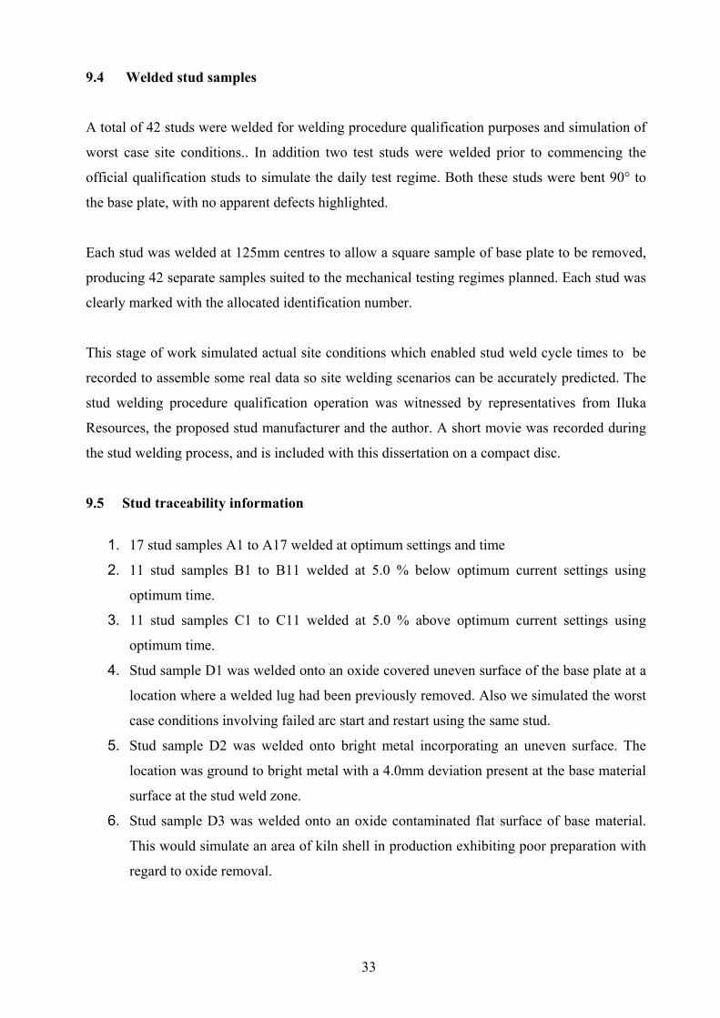
9.4 Welded stud samples.....................................................................................33
9.5 Stud traceability information.........................................................................33
9.6 Samples to qualify the applied welding standards ........................................36
9.7 Additional test regimes..................................................................................36
9.8 Results of tensile testing and bend samples ..................................................36
9.9 Results of hardness testing using Vickers pyramid tester ( HV10 )..............40
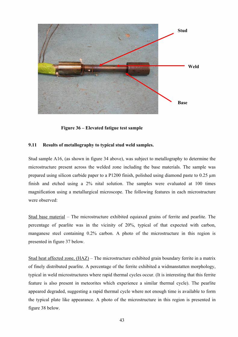
9.10 Results of elevated temperature fatigue test..................................................41
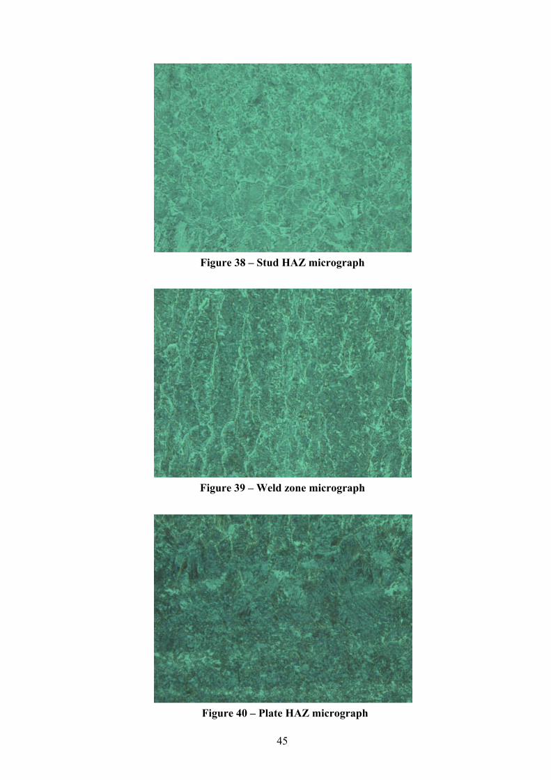
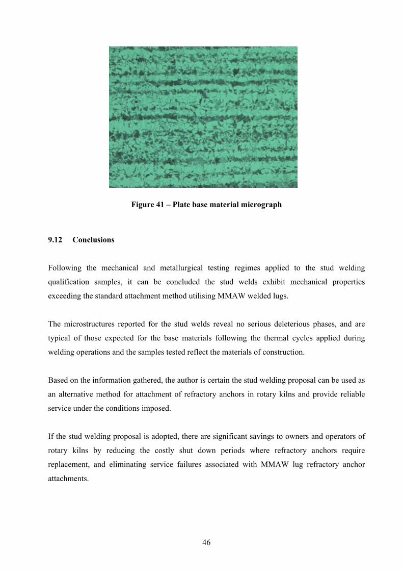
9.11 Results of metallography to typical stud weld samples ................................43
9.12 Conclusions........................................................................................................... 46
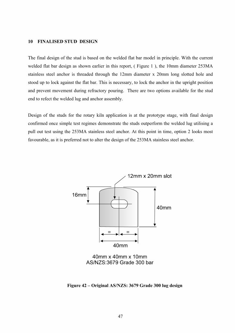
10 FINALISED STUD DESIGN................................................................................47
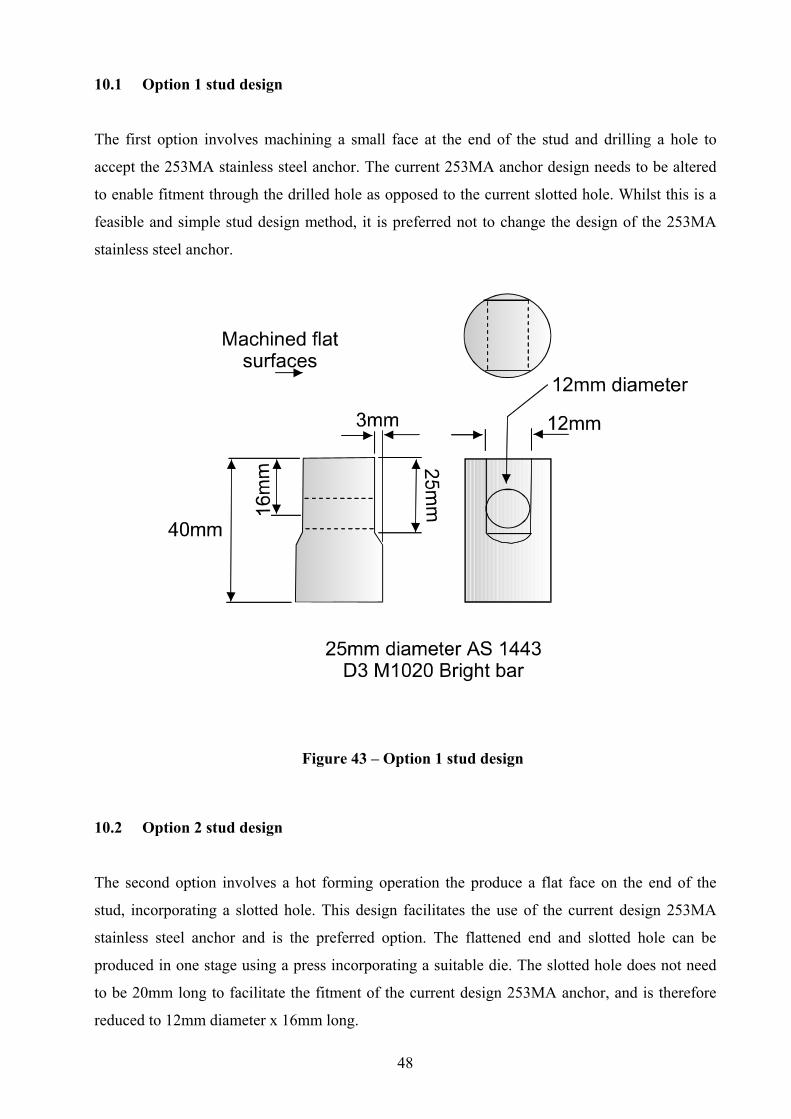
10.1 Option 1 stud design......................................................................................48
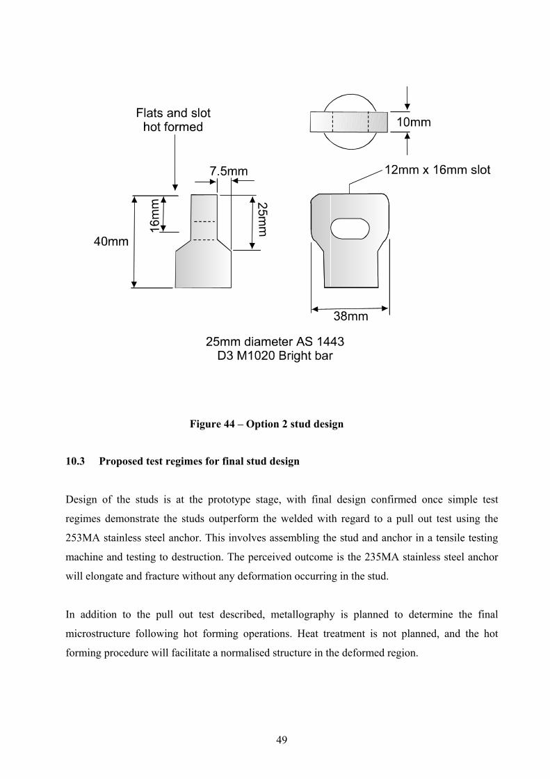
10.2 Option 2 stud design......................................................................................48
10.3 Proposed test regimes for final stud design...................................................49
11 APPLICATION TO ROTARY KILNS.................................................................50
11.1 Welding procedure ........................................................................................50
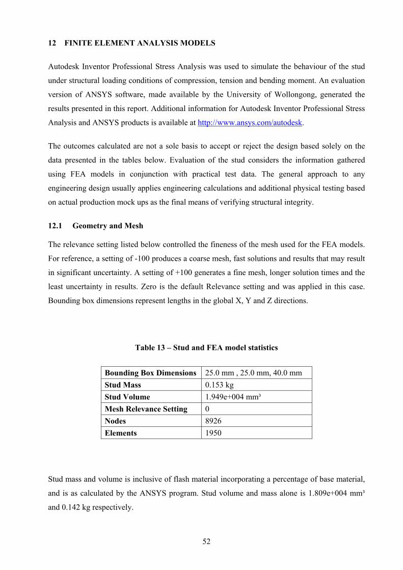
12 FINITE ELEMENT ANALYSIS MODELS.........................................................52
12.1 Geometry and mesh.......................................................................................52
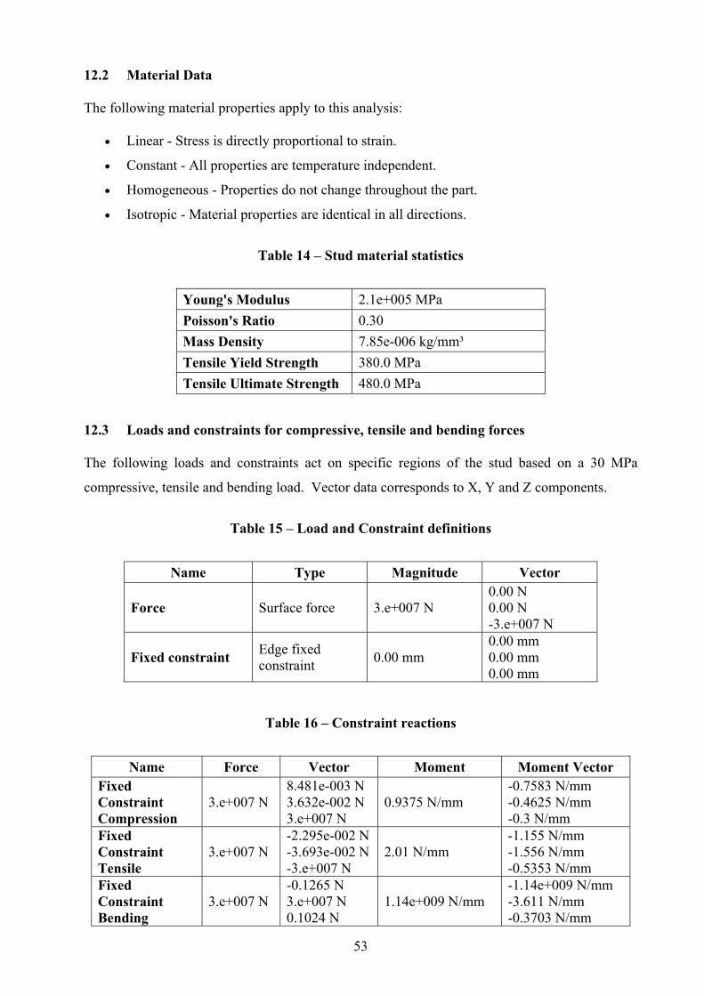
12.2 Material data..................................................................................................53
12.3 Loads and constraints for compression, tensile and bending forces .............53
Page 9
vii
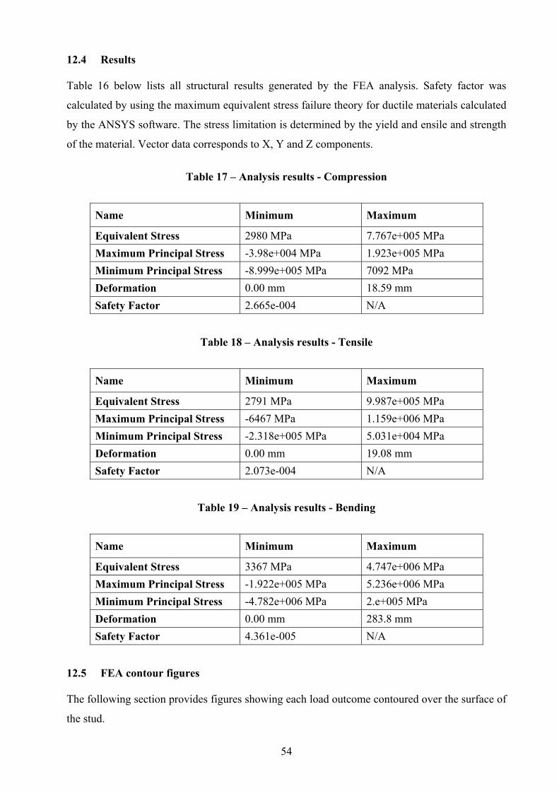
12.4 Results ...........................................................................................................54
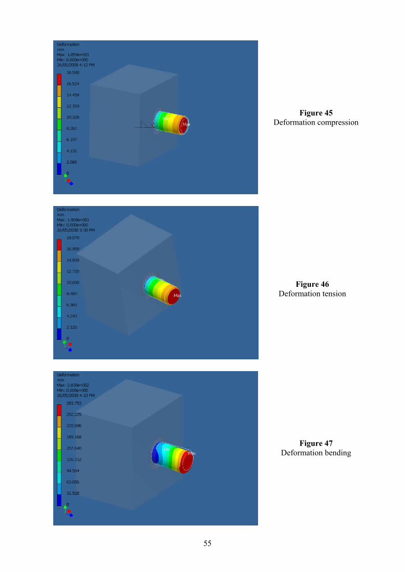
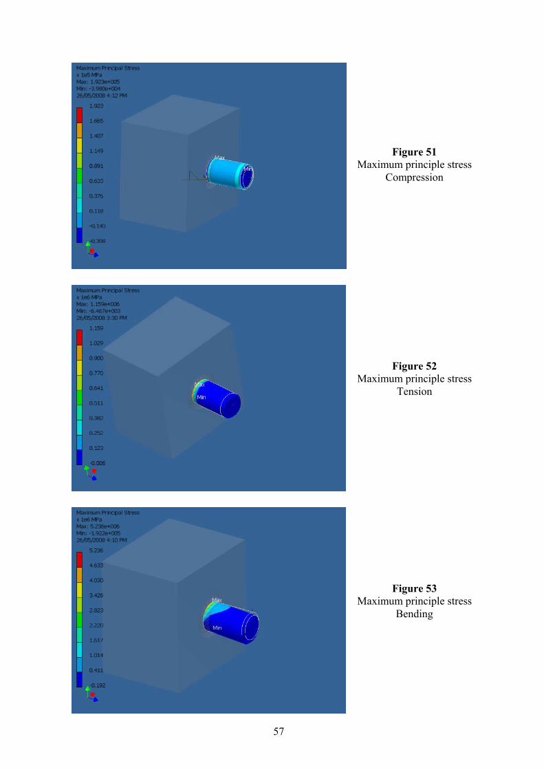
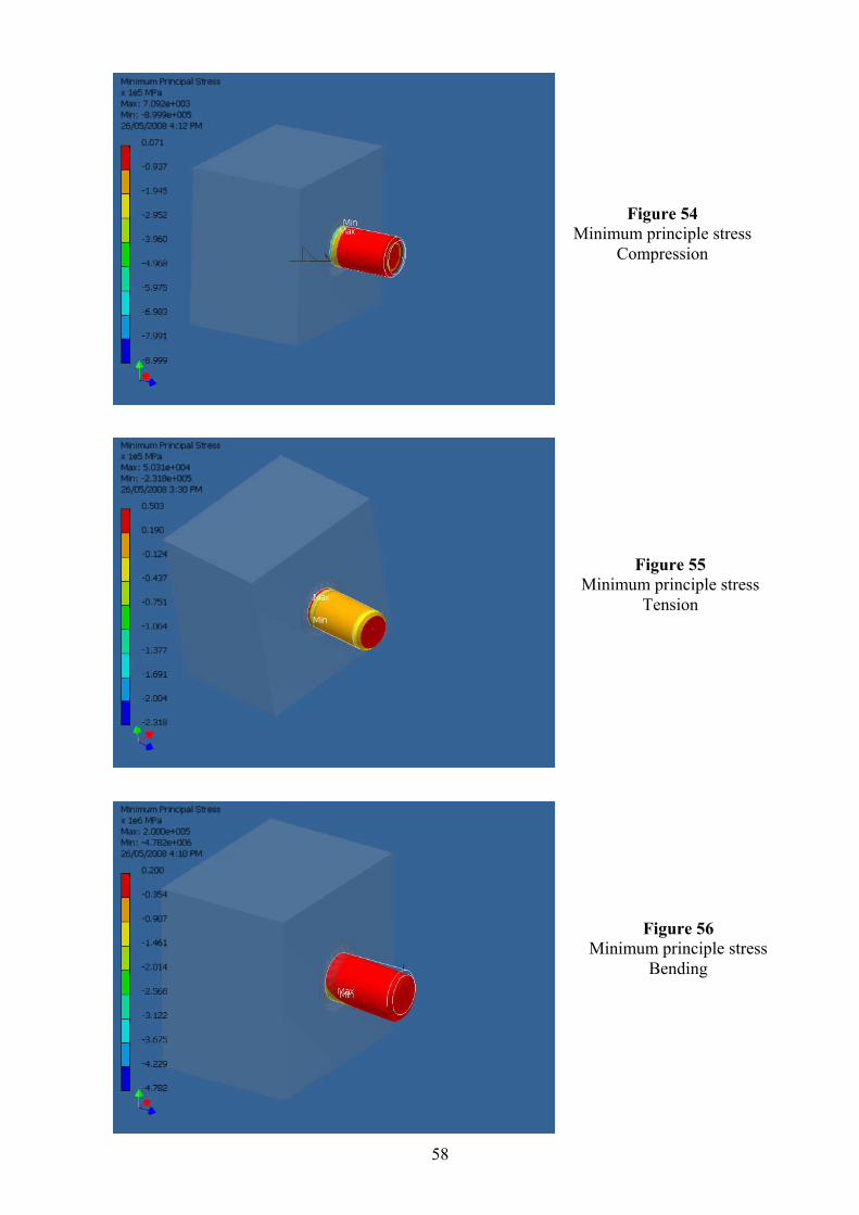
12.5 FEA contour figures ......................................................................................54
Deformation contour figures ....................................................................................55
Equivalent stress figures...........................................................................................56
Maximum principle stress figures ............................................................................57
Minimum principle stress figures.............................................................................58
Safety factor figures .................................................................................................59
Bibliography and list of references...........................................................................60
Appendix 1 – Stress range and load capacity calculations.......................................61
Page 10
viii
ABBREVIATIONS
AISI – American Iron and Steel Institute
ANSYS – Analytical system
AS – Australian Standard
AS/NZS – Australian and New Zealand Standard
ASTM – American Society for testing and materials
AWS – American Welding Society
CDSW – Capacitor discharge stud welding
DASW – Drawn arc stud welding
DCEN – Direct current electrode negative
E – Percentage of elongation
FEA – Finite element analysis
FL – Fusion line.
FSW – Friction stud welding
HAZ – Heat affected zone
HV – Hardness: Vickers pyramid method, ( HV10 – 10 kg load )
kN – Kilonewton
kg – Kilogram
MMAW – Manual metal arc welding
MPa – Megapascal
NDE – Non destructive examination
N - Newton
N/mm – Newton / millimetre
OD – Outside diameter
QA / QC – Quality control / Quality assurance
PT – Penetrant test
R of A – Reduction of area
SMYS – Specified minimum yield strength
SN – Stress / Number of cycles
TiO2 – Titanium Dioxide
TWI – The Welding Institute
UGI – Upgraded Ilmenite
UTS – Ultimate tensile strength
WTIA – Welding Technology Institute of Australia
Page 11
ix
NOTATIONS
frs – Uncorrected fatigue strength βtf – Thickness correction factor tp – Plate thickness Φ – Capacity factor frsc – Corrected fatigue strength f * – Design stress range F – Force σ – Stress A– Area µm - Micromillimetre °C - Degrees centigrade
Page 12
x
LIST OF TABLES Table 1 – AS/NZS: 1554 Part 2 - Table 2.1. Minimum stud material properties other than shear
connectors
Table 2 – AS: 1443 Table 6 Grade D3 M1020 minimum tensile properties
Table 3 – AS: 4100 load capacity comparisons between welded lugs and stud welds
Table 4 – AS: 4100 fatigue comparisons between welded lugs and stud welds
Table 5 – Results of AS: 1443 Grade D3 M1020 elevated temperature tensile tests
Table 6 – Summary of comparison test values
Table 7 – Summary of tensile tests welded at optimum current
Table 8 – Summary of tensile tests welded 5% below optimum current
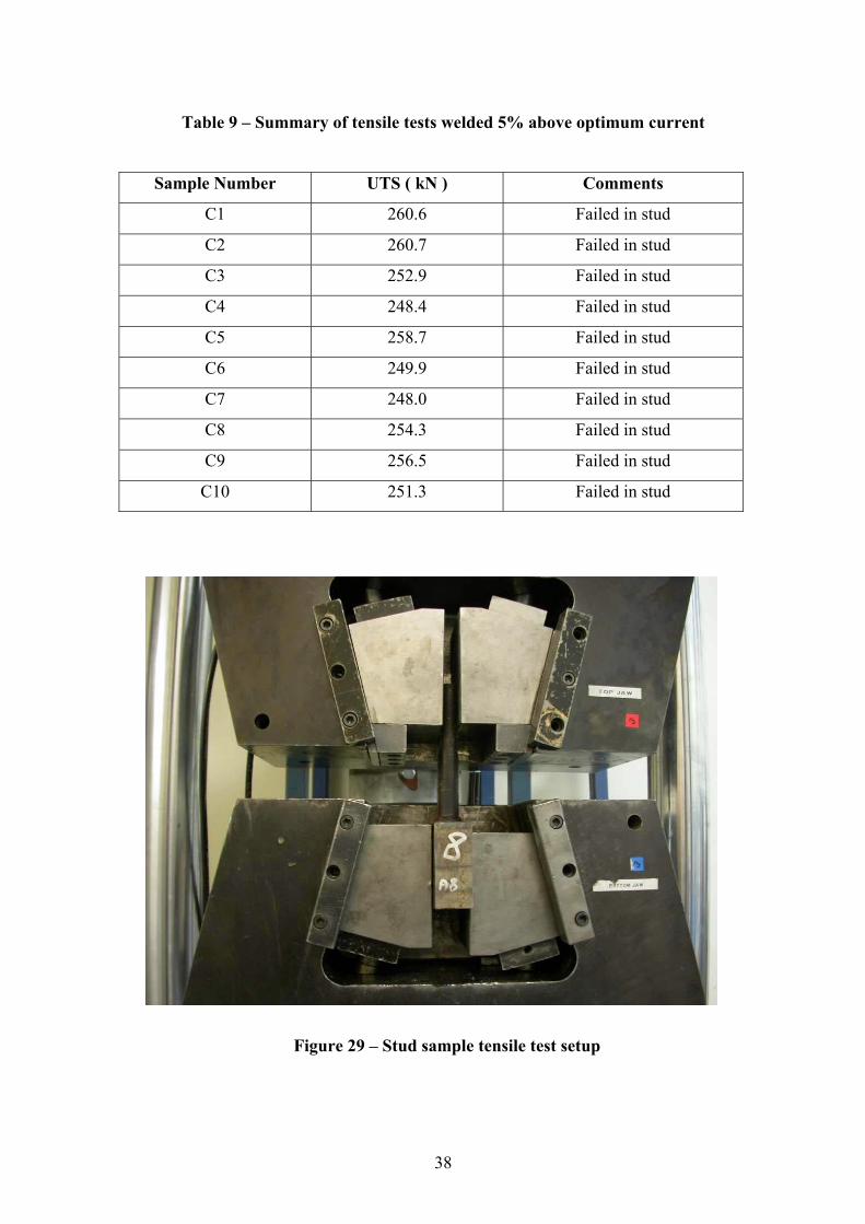
Table 9 – Summary of tensile tests welded 5% above optimum current
Table 10 – Summary of bend tests at optimum current
Table 11 – Summary of typical hardness testing within welding current range
Table 12 – Summary of elevated temperature fatigue test parameters
Table 13 – Stud and FEA model statistic
Table 14 – Stud material statistic
Table 15 – Load and Constraint definitions
Table 16 – Constraint reactions
Table 17 – Analysis results – Compression
Table 18 – Analysis results – Tensile
Table 19 – Analysis results – Bending
Page 13
xi
LIST OF FIGURES
Figure 1 – Rotor lok anchor arrangement Figure 2 – Fillet welded lug using MMAW Figure 3 – Nelson 6000 power source Figure 4 – Nelson P-NS 20 BHD stud gun Figure 5 – Stud samples and ferrules Figure 6 – Stud samples showing grade 1100 H16 aluminium flux ball Figure 7 and 8 – Preliminary stud weld bend tests Figure 9 and 10 – Shell sections demonstrating PT examination Figure 11 - Stud weld sample Figure 12 - Welded lug, 6mm fillet weld Figure 13 – Fatigue testing setup Figure 14 -Fatigue testing machine Figure 15 - Stud fracture face Figure 16 - Stud / shell interface Figure 17 - Lug weld fatigue fracture Figure 18 - Lug / shell interface Figure 19 – Stud macro at higher current and cycle time Figure 20 – Stud macro at lower current and cycle time, with modified lift / plunge data Figure 21 – Stud macro at optimum current and cycle time Figure 22 – Kiln shell section marked out for stud welding Figure 23 – Weld zone oxide removal Figure 24 – Stud sample test plate during welding Figure 25 – Completed test plate Figure 26 – Close up of stud sample A6
Page 14
xii
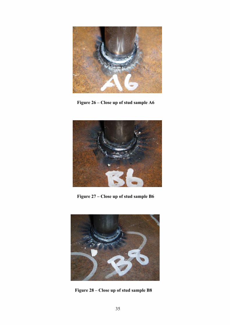
Figure 27 – Close up of stud sample B6 Figure 28 – Close up of stud sample B8 Figure 29 – Stud sample tensile test setup Figure 30 / 31 – Typical necking and stud failure Figure 32 / 33 – Typical bending sample Figure 34 – Typical macro sample incorporating HV10 survey welded within acceptable parameter ranges Figure 35 – Elevated fatigue test setup Figure 36 – Elevated fatigue test sample Figure 37 – Stud base material micrograph Figure 38 – Stud HAZ micrograph Figure 39 – Weld zone micrograph Figure 40 – Plate HAZ micrograph Figure 41 – Plate base material micrograph Figure 42 – Original AS/NZS: 3679 Grade 300 lug design Figure 43 – Option 1 stud design Figure 44 – Option 2 stud design Figure 45 - Deformation compression Figure 46 - Deformation tension Figure 47 - Deformation bending Figure 48 - Equivalent stress: compression Figure 49 - Equivalent stress: tension Figure 50 - Equivalent stress: bending Figure 51 - Maximum principle stress: compression Figure 52 - Maximum principle stress: tension Figure 53 - Maximum principle stress: bending
Page 15
xiii
Figure 54 - Minimum principle stress: compression Figure 55 - Minimum principle stress: tension Figure 56 - Minimum principle stress: bending Figure 57 - Safety factor: compression Figure 58 - Safety factor: tension Figure 59 - Safety factor: bending
Page 16
1
1 INTRODUCTION
As briefly detailed in the abstract, the rotary kilns where this work will be applied are fabricated
from AS:1548-7-460R carbon manganese steel and are approximately 70.0 metres long and 6.0
metres in diameter. The kilns are supported and turned by a geared rotation arrangement via an
AISI 4140 tyre attached to the shell using a complex assembly of blocks and wedges. These
allow expansion of the shell beneath the tyres to ensure constant tyre / rotator contact during
thermal cycling and associated dimensional variations.
The kilns are coal fired resulting in an internal operating temperature of approximately 1200°C
and rotate at approximately one revolution per minute. The kilns are located at Iluka’s mineral
separation plant situated approximately 450 kilometres north of Perth in the industrial area of
Geraldton, Western Australia. The mineral ilmenite, an iron/titanium oxide, is transported to the
refinery to be upgraded to a synthetic rutile mineral, (upgraded ilmenite or UGI), containing
between 88% and 95% highly valued titanium dioxide (TiO2).
Upgrading the ilmenite involves a two stage process. The first pyrometallurgical stage involves
heating the mineral within a rotary kiln in the presence of a reductant. This converts the iron
oxide impurities within the ilmenite to metallic iron, which is then removed by the second stage
of refining treatment. The rotary kilns discharge between 24 to 31 tonnes of reduced ilmenite
per hour. The second hydrometallurgical stage involves the removal of metallic iron by oxidation
and leaching resulting in upgraded ilmenite.
By incorporating specific additives such as sulphur or hydroboracite during the
pyrometallurgical stage and modifying the leaching conditions in the hydrometallurgical stage,
three grades of titanium dioxide are produced. Each grade reflects the purity of the titanium
dioxide due to removal of different portions of the non-titanium elements from the original
ilmenite.
Due to the 1200°C operating temperature inside the rotary kiln to reduce the ilmenite, the shell is
protected internally by applying a cast refractory. This reduces the kiln shell temperature beneath
the refractory to below 200°C maximum.
Page 17
2
1.1 Refractory Anchor Current Practice
The refractory is poured in strips within a mould approximately 1000mm wide and 250mm deep
along the bottom of the kiln and allowed to set. Attachment to the kiln shell is achieved using
AS/NZS: 3679 Grade 300 mild steel lugs fillet welded using the manual metal arc welding
process, AS: 1553 Part 1 E4818 electrodes and welding procedures qualified to AS/NZS:1554
Part 1 SP. The lug incorporated a slotted hole, through which a 253MA stainless steel anchor is
supported. This anchor sits within the poured refractory. This arrangement is supplied by
Pressform Engineering and is referred to as a “rotor lok” anchor, details are shown in figure 1
and 2 below.
There are approximately 13,000 welded lugs within the kiln, each supporting a 253MA stainless
steel anchor. Over a 3 year period of service, degradation of the internal refractory requires the
kiln to be shut down and the refractory replaced. The refractory is broken up using hydraulic jack
hammers. During this operation, many refractory anchors and welded lugs are damaged beyond
repair, so replacement is necessary. In addition, many welded lugs show signs of unacceptable
wear within the slotted hole, also requiring replacement.
Figure 1 – Rotor lok anchor arrangement Figure 2 – Fillet welded lug using MMAW
Page 18
3
During service, failure of a welded lug is a common problem, resulting in significant loss of
refractory lining and overheating of the kiln shell. Whilst water spray is directed at the kiln shell
during service to reduce the shell temperature where refractory failure is present, this occurrence
always results in costly shutdown and repair operations. There have also been several occasions
where permanent damage to the shell material has transpired, caused by long term exposure to
elevated temperature and spherodising of cementite plates within the pearlite leading to total
collapse of the shell material. This is demonstrated by severe full thickness cracks in areas
subjected to prolonged elevated temperature exposure in the region of 700°C - 800°C. In these
cases, sections of affected shell material are removed and replaced.
The quality of the welded lug is critical to ensure refractory integrity during kiln operation and
the welding stage must be strictly controlled. The current welding operations and procedures
require a high level of qualification and surveillance activities to ensure acceptable quality on a
consistent basis. Moves to apply AS/NZS:1554 Part 5 have been resisted, as the process of
welding the lugs inside the kiln shell is already a very expensive exercise, and factors
contributing to lug failure including undercut, notches etc, are avoided. The time required to
smoothly blend all the fillet welds to comply with the visual acceptance criteria of AS/NZS:1554
Part 5 would greatly contribute to the overall cost during the shutdown period, and based on the
weld quality evident on lugs that do not fail during the service period, AS/NZS:1554 Part 5
criteria is deemed unnecessary.
Despite this, applying reliable 100% surveillance / assurance activities to some 13,000 welded
lugs is difficult, and the onus is on the welding operator and non destructive testing technician to
guarantee weld quality. It is inevitable some undesirable discontinuities are either overlooked or
missed entirely during the examination stage. The presence of defects directly contributable to
welded lug failure during service is considered high despite the QA / QC regimes applied.
The lug welding stage during kiln shutdown normally takes between 3 to 4 weeks, hence the
high costs associated with this work. Based on site observations during a shut down period, the
idea of using welded studs to support the refractory anchor appeared logical. The stud welding
proposal was presented to Iluka Resources and accepted with enthusiasm, therefore the idea of
applying studs was to be investigated and researched with support from Iluka Resources.
Page 19
4
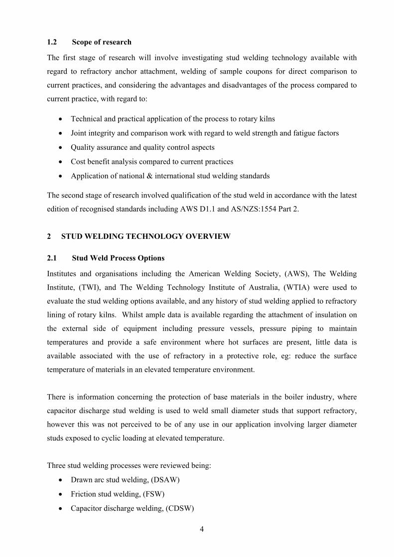
1.2 Scope of research
The first stage of research will involve investigating stud welding technology available with
regard to refractory anchor attachment, welding of sample coupons for direct comparison to
current practices, and considering the advantages and disadvantages of the process compared to
current practice, with regard to:
• Technical and practical application of the process to rotary kilns
• Joint integrity and comparison work with regard to weld strength and fatigue factors
• Quality assurance and quality control aspects
• Cost benefit analysis compared to current practices
• Application of national & international stud welding standards
The second stage of research involved qualification of the stud weld in accordance with the latest
edition of recognised standards including AWS D1.1 and AS/NZS:1554 Part 2.
2 STUD WELDING TECHNOLOGY OVERVIEW
2.1 Stud Weld Process Options
Institutes and organisations including the American Welding Society, (AWS), The Welding
Institute, (TWI), and The Welding Technology Institute of Australia, (WTIA) were used to
evaluate the stud welding options available, and any history of stud welding applied to refractory
lining of rotary kilns. Whilst ample data is available regarding the attachment of insulation on
the external side of equipment including pressure vessels, pressure piping to maintain
temperatures and provide a safe environment where hot surfaces are present, little data is
available associated with the use of refractory in a protective role, eg: reduce the surface
temperature of materials in an elevated temperature environment.
There is information concerning the protection of base materials in the boiler industry, where
capacitor discharge stud welding is used to weld small diameter studs that support refractory,
however this was not perceived to be of any use in our application involving larger diameter
studs exposed to cyclic loading at elevated temperature.
Three stud welding processes were reviewed being:
• Drawn arc stud welding, (DSAW)
• Friction stud welding, (FSW)
• Capacitor discharge welding, (CDSW)
Page 20
5
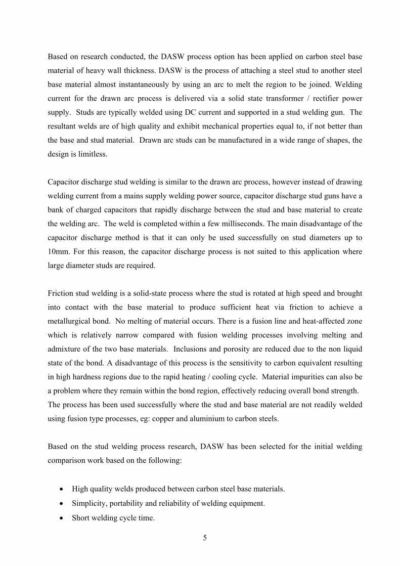
Based on research conducted, the DASW process option has been applied on carbon steel base
material of heavy wall thickness. DASW is the process of attaching a steel stud to another steel
base material almost instantaneously by using an arc to melt the region to be joined. Welding
current for the drawn arc process is delivered via a solid state transformer / rectifier power
supply. Studs are typically welded using DC current and supported in a stud welding gun. The
resultant welds are of high quality and exhibit mechanical properties equal to, if not better than
the base and stud material. Drawn arc studs can be manufactured in a wide range of shapes, the
design is limitless.
Capacitor discharge stud welding is similar to the drawn arc process, however instead of drawing
welding current from a mains supply welding power source, capacitor discharge stud guns have a
bank of charged capacitors that rapidly discharge between the stud and base material to create
the welding arc. The weld is completed within a few milliseconds. The main disadvantage of the
capacitor discharge method is that it can only be used successfully on stud diameters up to
10mm. For this reason, the capacitor discharge process is not suited to this application where
large diameter studs are required.
Friction stud welding is a solid-state process where the stud is rotated at high speed and brought
into contact with the base material to produce sufficient heat via friction to achieve a
metallurgical bond. No melting of material occurs. There is a fusion line and heat-affected zone
which is relatively narrow compared with fusion welding processes involving melting and
admixture of the two base materials. Inclusions and porosity are reduced due to the non liquid
state of the bond. A disadvantage of this process is the sensitivity to carbon equivalent resulting
in high hardness regions due to the rapid heating / cooling cycle. Material impurities can also be
a problem where they remain within the bond region, effectively reducing overall bond strength.
The process has been used successfully where the stud and base material are not readily welded
using fusion type processes, eg: copper and aluminium to carbon steels.
Based on the stud welding process research, DASW has been selected for the initial welding
comparison work based on the following:
• High quality welds produced between carbon steel base materials.
• Simplicity, portability and reliability of welding equipment.
• Short welding cycle time.
Page 21
6
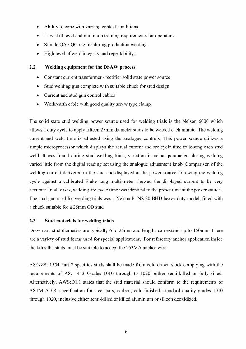
• Ability to cope with varying contact conditions.
• Low skill level and minimum training requirements for operators.
• Simple QA / QC regime during production welding.
• High level of weld integrity and repeatability.
2.2 Welding equipment for the DSAW process
• Constant current transformer / rectifier solid state power source
• Stud welding gun complete with suitable chuck for stud design
• Current and stud gun control cables
• Work/earth cable with good quality screw type clamp.
The solid state stud welding power source used for welding trials is the Nelson 6000 which
allows a duty cycle to apply fifteen 25mm diameter studs to be welded each minute. The welding
current and weld time is adjusted using the analogue controls. This power source utilizes a
simple microprocessor which displays the actual current and arc cycle time following each stud
weld. It was found during stud welding trials, variation in actual parameters during welding
varied little from the digital reading set using the analogue adjustment knob. Comparison of the
welding current delivered to the stud and displayed at the power source following the welding
cycle against a calibrated Fluke tong multi-meter showed the displayed current to be very
accurate. In all cases, welding arc cycle time was identical to the preset time at the power source.
The stud gun used for welding trials was a Nelson P- NS 20 BHD heavy duty model, fitted with
a chuck suitable for a 25mm OD stud.
2.3 Stud materials for welding trials
Drawn arc stud diameters are typically 6 to 25mm and lengths can extend up to 150mm. There
are a variety of stud forms used for special applications. For refractory anchor application inside
the kilns the studs must be suitable to accept the 253MA anchor wire.
AS/NZS: 1554 Part 2 specifies studs shall be made from cold-drawn stock complying with the
requirements of AS: 1443 Grades 1010 through to 1020, either semi-killed or fully-killed.
Alternatively, AWS:D1.1 states that the stud material should conform to the requirements of
ASTM A108, specification for steel bars, carbon, cold-finished, standard quality grades 1010
through 1020, inclusive either semi-killed or killed aluminium or silicon deoxidized.
Page 22
7
Stud materials will be selected based on AS/NZS: 1554 Part 2 table 2.1 for studs other than shear
connectors as below:
Table 1 – AS/NZS: 1554 Part 2 - Table 2.1.
Minimum stud material properties other than shear connectors
Property Requirement
Minimum tensile strength 380 MPa
Minimum yield strength N/A
Minimum % E on a 50mm gauge length 10%
Minimum R of A 50%
For the purpose of stud welding comparison trails and stud welding qualification, AS: 1443
Grade D3 - M1020 has been selected. This material exhibits all the AS/NZS: 1554 part 2
mechanical property requirements at ambient temperature for shear connectors and studs other
than these, and the minimum tensile and yield strength is maintained at 200°C, based on elevated
temperature tensile testing values referenced in table 5 of this report. Reference can also be made
to table 3.3.9 in AS: 1210 where carbon, manganese steels of similar composition exhibit no
reduction in design strength up to 200°C.
Table 2 – AS: 1443 Table 6 Grade D3 M1020 minimum tensile properties
Property Requirement
Minimum tensile strength 460 MPa
Minimum yield strength 370 MPa
Minimum % E on a 50mm gauge length 12%
Studs used for welding comparisons and welding qualification will be AS: 1443 Grade D3 -
M1020 material 25mm OD and 150mm long. This will enable a suitable test piece to be
completed to enable mechanical testing. The final design of the stud at this stage is not finalised.
I am working closely with Pressform Engineering to determine the final stud design. If hot or
cold forming operations are required, metallography and material assessments will be conducted
to ensure no deleterious microstructure alteration / damage has occurred. Once the design is
confirmed, and metallography competed, the information gathered will be incorporated further
into this report.
Page 23
8
3 APPLICATION TO ROTARY KILNS
3.1 Weldability and metallurgical considerations
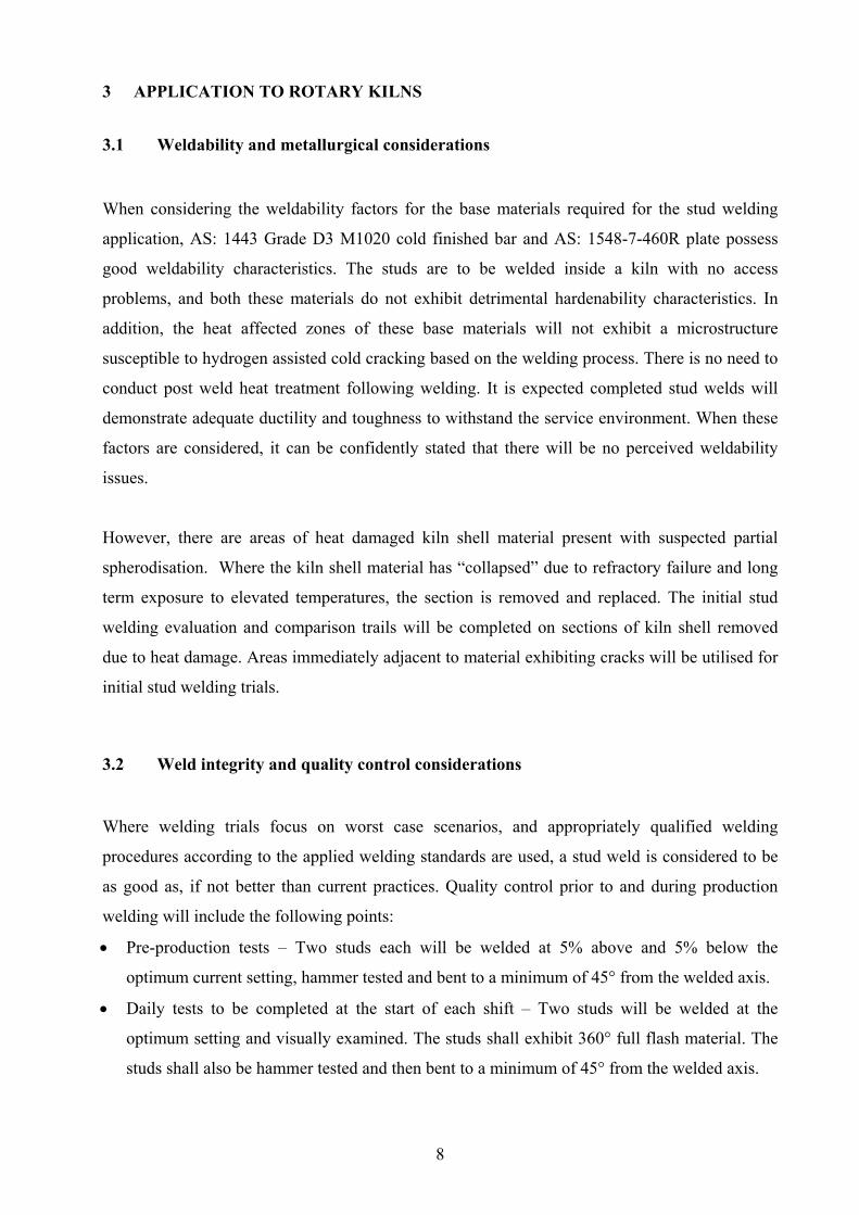
When considering the weldability factors for the base materials required for the stud welding
application, AS: 1443 Grade D3 M1020 cold finished bar and AS: 1548-7-460R plate possess
good weldability characteristics. The studs are to be welded inside a kiln with no access
problems, and both these materials do not exhibit detrimental hardenability characteristics. In
addition, the heat affected zones of these base materials will not exhibit a microstructure
susceptible to hydrogen assisted cold cracking based on the welding process. There is no need to
conduct post weld heat treatment following welding. It is expected completed stud welds will
demonstrate adequate ductility and toughness to withstand the service environment. When these
factors are considered, it can be confidently stated that there will be no perceived weldability
issues.
However, there are areas of heat damaged kiln shell material present with suspected partial
spherodisation. Where the kiln shell material has “collapsed” due to refractory failure and long
term exposure to elevated temperatures, the section is removed and replaced. The initial stud
welding evaluation and comparison trails will be completed on sections of kiln shell removed
due to heat damage. Areas immediately adjacent to material exhibiting cracks will be utilised for
initial stud welding trials.
3.2 Weld integrity and quality control considerations
Where welding trials focus on worst case scenarios, and appropriately qualified welding
procedures according to the applied welding standards are used, a stud weld is considered to be
as good as, if not better than current practices. Quality control prior to and during production
welding will include the following points:
• Pre-production tests – Two studs each will be welded at 5% above and 5% below the
optimum current setting, hammer tested and bent to a minimum of 45° from the welded axis.
• Daily tests to be completed at the start of each shift – Two studs will be welded at the
optimum setting and visually examined. The studs shall exhibit 360° full flash material. The
studs shall also be hammer tested and then bent to a minimum of 45° from the welded axis.
Page 24
9
• The stud welding equipment planned does not record each welding cycle. Obtaining arc
monitoring equipment suitable for solid state power sources for stud welding has proven
difficult. Persuading stud welding contractors to purchase equipment that records welding
parameters is problematic, they prefer to use robust type power sources with minimal
electronics. However the Nelson 6000 power source does display the actual welding current
and arc time used for each stud weld, and this is relatively easy to monitor during production.
The welding procedure will be qualified at 5% above and below optimum settings, ( based on
a 25mm stud ), therefore there is a reasonable scope for welding parameters where
mechanical properties, stud weld integrity and visual properties can be assured during
mechanical testing regimes.
• Due to the use of non arc monitoring equipment referenced above, any change in welding
procedure within the 5 % range each side of the optimum settings during production shall
require the daily tests off the job to be completed prior to recommencement of production
welding.
• In addition, a quality control regime for production welding will incorporate two off the job
tests as per the daily test method for each 250 studs applied on the kiln shell.
• Each stud on the kiln shell shall be subjected to a hammer test and visual examination. All
studs welded on the kiln shell shall exhibit 100 % exposed flash and pass a hammer test.
Those not complying with the tests applied, not welded in accordance with the qualified
welding procedure or any other doubt exists regarding the weld integrity, eg; base material
condition etc, the stud shall be removed by grinding methods and rewelded.
3.3 Welding process limitations
Section 3.1 of AS/NZS: 1554 Part 2 outlines the criteria for the prequalification of studs. The
code states that studs that are “applied in the flat position to a flat and horizontal surface are
deemed prequalified” and need no further testing. In this requirement, the flat position is defined
as a <15° slope on the applicable surface.
It is planned to conduct welding procedure qualifications and manufacturer qualification regimes
for stud welding within the 15° limitations. All studs will be welded within the 15° limits during
production. This is taking operator safety into consideration, where welding outside the 15° limit
inside the rotary kiln may lead to slips and falls. With dozens of studs welded to the kiln shell
adjacent to the operator, there is significant risk of injury, therefore the 15° limit will be imposed
for production welding.
Page 25
10
It was found during stud welding trails, that the flash contour is affected by gravity when studs
were applied at > 15°. On occasion, the flash was not established 360° around the stud base. At
0° to 10°, there is little effect on the flash extent and contour.
4 JOINT WELD STRENGTH AND FATIGUE CONSIDERATIONS
Prior to commencing any stud welding trials and comparisons to current practices, weld joint
load capacity has been evaluated using AS: 4100. Calculations detailed in this standard were
used to compare welded lugs and stud welds based on load capacity at 1000 kg This data was
used to determine an appropriate stud diameter to achieve the equivalent strength to the currently
used AS/NZS: 3678 Grade 300 mild steel lug of 40mm x 10mm welded using a 6mm and 8mm
fillet weld leg length.
4.1 Weld strength / load capacity comparisons
The data collated in Table 3 below is based on low hydrogen 480 MPa tensile strength
consumables to AS: 1553 Part 1 and AS/NZS: 1554 Part 1 SP category for the fillet welds. The
equations used are detailed in Appendix A
Table 3 – AS: 4100 load capacity comparisons between welded lugs and stud welds
Item 40 x 10 lug
6mm fillet
40 x 10 lug
8mm fillet
20mm
OD stud
22mm
OD stud
25mm
OD stud
27mm
OD stud
30mm
OD stud
Stress at
1000 kg 23.5 MPa 17.5 MPa 31 MPa 25 MPa 20 MPa 17 MPa 13 MPa
Based on the information gathered using calculations from AS:4100 in table 3 above, it is
apparent a 25mm stud is required to replace a 40mm x 10mm lug with a 6mm fillet and a 27mm
stud to replace a 40mm x 10mm lug with an 8mm fillet. Considering a 6mm fillet is used as the
basis of design for the welded lugs on the kiln shell, a 25mm stud diameter will be selected based
on the data from table 3.
Page 26
11
It should be noted that 8mm fillets have been applied to the lugs inside the kiln shell, however
there has been no reported improvement in service life based on a larger fillet weld applied. In
addition, the application of an 8mm fillet requires multiple passes, hence greater cost and
attempts to complete the weld in one pass has resulted in discontinuities outside acceptable
limitations under AS/NZS:1554 Part 1 SP acceptance criteria.
4.2 Weld fatigue considerations
The lugs that support the 253MA refractory anchor were perceived to be subject to shear
stresses, tensile and compression forces during each kiln rotation cycle. Based on discussions
with Iluka design engineers, the bending moment / shear stress applied to the welded lug is
negligible due to the nature of the refractory, and compression is not perceived to be an issue.
The estimated weight supported by each stud is approximately 250kg, imposing in the region of
7.5 MPa of stress. This is applied to the welded lug at the top section of the kiln during rotation,
where the weight of the refractory is hanging from the anchor applying a direct tensile force.
Fatigue performance comparisons at the design stress range between fillet welded lugs and stud
welds were evaluated using AS:4100 Section 11. The data is based on the stud being the same
length as the welded lugs currently in production. To predict values for direct comparison
purposes between fillet weld lugs and stud welds, a 106 cycle factor has been used. The
following sections and tables in AS:4100 have been used as reference:
• All joint designs based on category 80 in table 11.5.1 (2)
• SN curve data for uncorrected fatigue strength (frs) from figure 11.6.2
• Thickness correction factor (βtf) taken as 1.0 from 11.1.7 ≤ 25mm thickness
• Thickness correction factor (βtf) calculated using 11.7.1 for > 25mm thickness
• Capacity factor (Φ) taken as 0.7 from 11.1.6
• Using corrected fatigue strength (frsc) equation from 11.1.7
• Calculating the design stress range, ( f * ), using equation from 11.8.1.
Page 27
12
Table 4 – AS: 4100 fatigue comparisons between welded lugs and stud welds
Item 40 x 10 lug
6mm fillet
40 x 10 lug
8mm fillet
20mm
OD stud
22mm
OD stud
25mm
OD stud
27mm
OD stud
30mm
OD stud
Design
Stress
Range
63.0
MPa
63.0
MPa
63.0
MPa
63.0
MPa
63.0
MPa
61.75
MPa
59.85
MPa
Allowable
Force
275.0
kN
367.0
kN
204.0
kN
255.0
kN
321.0
kN
377.0
kN
438.0
kN
Allowable
Load 2700 kg 3600 kg 2000 kg 2500 kg 3150 kg 3700 kg 4300 kg
Looking at the values obtained in table 4, it is apparent a stud diameter between 22mm and
25mm stud is required to replace a 40mm x 10mm lug with a 6mm fillet. Considering standard
bar sizes available, and to provide an extra degree of comfort, a 25mm stud again will be
selected. Based on the load and stress imparted by the refractory during service, a 20mm stud is
adequate, however there is little difference in cost and weld cycle time in selecting the larger
stud with the added confidence in serviceability under the rigorous conditions, including elevated
temperature.
4.3 Temperature, stress concentrations and weld quality
In addition to the strength and fatigue factors discussed above in the text and tables, other factors
need to be considered which may contribute to premature failure of the stud weld. These include:
• Elevated temperature and loss of properties
• Stress concentrations reducing the fatigue life
• Overall weld quality
Provided temperatures do not exceed 200°C at the interface between the stud and the kiln shell,
there will be no detrimental reduction in mechanical properties of the AS:1443 grade D3 M1020
Page 28
13
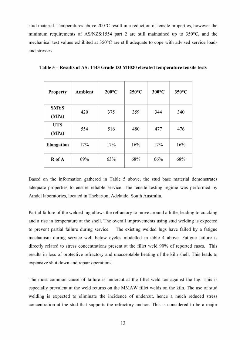
stud material. Temperatures above 200°C result in a reduction of tensile properties, however the
minimum requirements of AS/NZS:1554 part 2 are still maintained up to 350°C, and the
mechanical test values exhibited at 350°C are still adequate to cope with advised service loads
and stresses.
Table 5 – Results of AS: 1443 Grade D3 M1020 elevated temperature tensile tests
Property Ambient 200°C 250°C 300°C 350°C
SMYS
(MPa) 420 375 359 344 340
UTS
(MPa) 554 516 480 477 476
Elongation 17% 17% 16% 17% 16%
R of A 69% 63% 68% 66% 68%
Based on the information gathered in Table 5 above, the stud base material demonstrates
adequate properties to ensure reliable service. The tensile testing regime was performed by
Amdel laboratories, located in Thebarton, Adelaide, South Australia.
Partial failure of the welded lug allows the refractory to move around a little, leading to cracking
and a rise in temperature at the shell. The overall improvements using stud welding is expected
to prevent partial failure during service. The existing welded lugs have failed by a fatigue
mechanism during service well below cycles modelled in table 4 above. Fatigue failure is
directly related to stress concentrations present at the fillet weld 90% of reported cases. This
results in loss of protective refractory and unacceptable heating of the kiln shell. This leads to
expensive shut down and repair operations.
The most common cause of failure is undercut at the fillet weld toe against the lug. This is
especially prevalent at the weld returns on the MMAW fillet welds on the kiln. The use of stud
welding is expected to eliminate the incidence of undercut, hence a much reduced stress
concentration at the stud that supports the refractory anchor. This is considered to be a major
Page 29
14
improvement over welded lugs, and a more reliable service life and increased resistance to
fatigue initiated cracks is expected.
The overall weld quality and repeatability using stud welding is improved in comparison to
manual metal arc welding, (MMAW), due to a number of factors. There are no consumables
required for stud welding removes the husbandry required for currently used low hydrogen
welding electrodes. Poorly handled welding electrodes can result in elevated levels of hydrogen
in the deposited welds, leading to possible hydrogen assisted cold cracking problems. Stud
welding requires no consumables other than the stud, however cleanliness of the base material
and stud is still necessary to prevent elevated levels of hydrogen. Stud weld chemistry is
predictable, as the base and stud materials vary little in composition. Operator fatigue has an
effect on MMAW weld quality, where the desired fillet weld size and shape deteriorate and
presence of stress concentrations including undercut can increase to a point of non compliance.
Also, other unseen defects including lack of root fusion can severely reduce the fatigue
properties of MMAW welded lugs. Stud weldmetal volumes and absence of deleterious
discontinuities is highly repeatable based on set welding cycles therefore reliable mechanical
properties are assured for each stud that passes the quality control regimes applied to all
production studs.
The environment for attaching the welded lugs does not lend itself to comfortable MMAW, so
welders can suffer loss of concentration in a short space of time. The same is apparent for the
NDE operators and welding inspectors, where non compliant stress concentrations and
discontinuities are often missed. Stud welding reduces all these issues as the stud welding cycle
is very short, and operators are far more comfortable applying the stud welds. In addition the
NDE regime is far simpler, consisting of simple visual examination of exposed flash materials
and hammer test followed by simple identification, eg paint mark, to show quality control
regimes have been completed on that particular stud.
Page 30
15
5 STUD WELDING TIMES COMPARISON
Following consultation with the Perth based stud supply and welding company, STUDCO, and
data from Iluka Resources for the conventional MMAW anchor welding times, the following
data has been compiled to demonstrate the significant cost savings if stud welding is applied to
support the refractory inside the kiln shell:
5.1 DASW welding time estimates
Based on two stud welding machines, each with a two man team capable of completing 200 stud
welds per hour, approximately 4,800 studs can be installed per 24 hour period with two day shift
and two night shift teams, ( eight personnel ). At this production rate, a kiln with 13,000 studs
could theoretically be completed in three days.
This can be reduced further as the stud weld cycle time is only 1.2 seconds, and based on good
teamwork, five studs can easily be applied per minute, equating to 300 per hour enabling 7200
studs to be completed in a 24 hour period. Note that the three day estimate includes production
testing, and quality control regimes to the production studs.
This estimate also assumes the spot grinding and marking out of stud locations inside the kiln are
completed before stud welding begins and the welding environment needs to be clean and with
good visibility so that the welders can work efficiently.
The 25mm studs can only be welded in the flat position or with a relatively small inclination up
to 15°. This is based on welding trials conducted to old kiln shell sections to gauge the effect of
gravity on the flash shape and extension around the stud base. At 15°, the flash exhibited less
than 100% coverage around the stud base. Whilst preliminary bend testing against the area of
little or no flash highlighted no immediate issues, it is planned to weld the studs within a 10°
tolerance where welding trials demonstrated no effect on flash extent.
To apply studs within the 10° limitation each side of 0°, several kiln rotations will be required
Factoring in the kiln rotations increases the overall welding time. A 30° kiln rotation will take
approximately one hour to complete, considering removal of all equipment, gaining permits and
conducting the rotation. Based on the area not incorporating studs between each 20° section, 11
rotations would be required, effectively adding half a 24 hour period to the total time required to
Page 31
16
complete 13,000 stud welds. Based on the stud welding time, the total hours required to
complete the stud welding would be approximately 84 hours.
Based on previous MMAW refractory anchor lug welding operations, 3,000 + man hours is
required. This accounts for six welders and two supervisors, this equates to approximately fifteen
24-hour days. This is significantly more than the estimated 3.5 to 4 days required for the stud
welding approach.
5.2 MMAW approximate cost
Iluka Resources have advised the welding 13,000 refractory anchor lugs using MMAW requires
approximately 3,000 man-hours costing around $ 300,000.00 and the material cost for the anchor
lugs is $13,000.00. Welding consumables, welding equipment cost is around $6,000.00 based on
400 kg of electrodes at $ 2,500 and $ 3,500.00 for equipment hire. In addition, third party non
destructive testing costs approximately $ 4,800.00. This equates to a total cost of around
$ 324,000.00.
5.3 DASW approximate cost
Based on 25mm diameter studs, aluminium flux ball as well as machining to accept the 253MA
anchor, the estimated cost per stud is $4.00, hence a cost of $52,000.00 for the studs. Labour
costs including equipment based on $ 150.00 per hour equates to $ 72,000.00. This allows for
one supervisor on each shift in addition to the four stud welding operators, total of five personnel
on each shift. No other consumables are required and quality control regimes are controlled by
the operators monitored by supervision personnel. This equates to a total cost of $ 124,000.00.
5.4 Costing conclusion
Stud welding provides a direct saving of around $ 200,000.00 over the conventional MMAW
refractory anchor lug welding practices. Additional production earnings will be available by
shortening the shut down period by ten days. In summary, there are significant savings and
additional earnings available if stud welding was employed.
.
Page 32
17
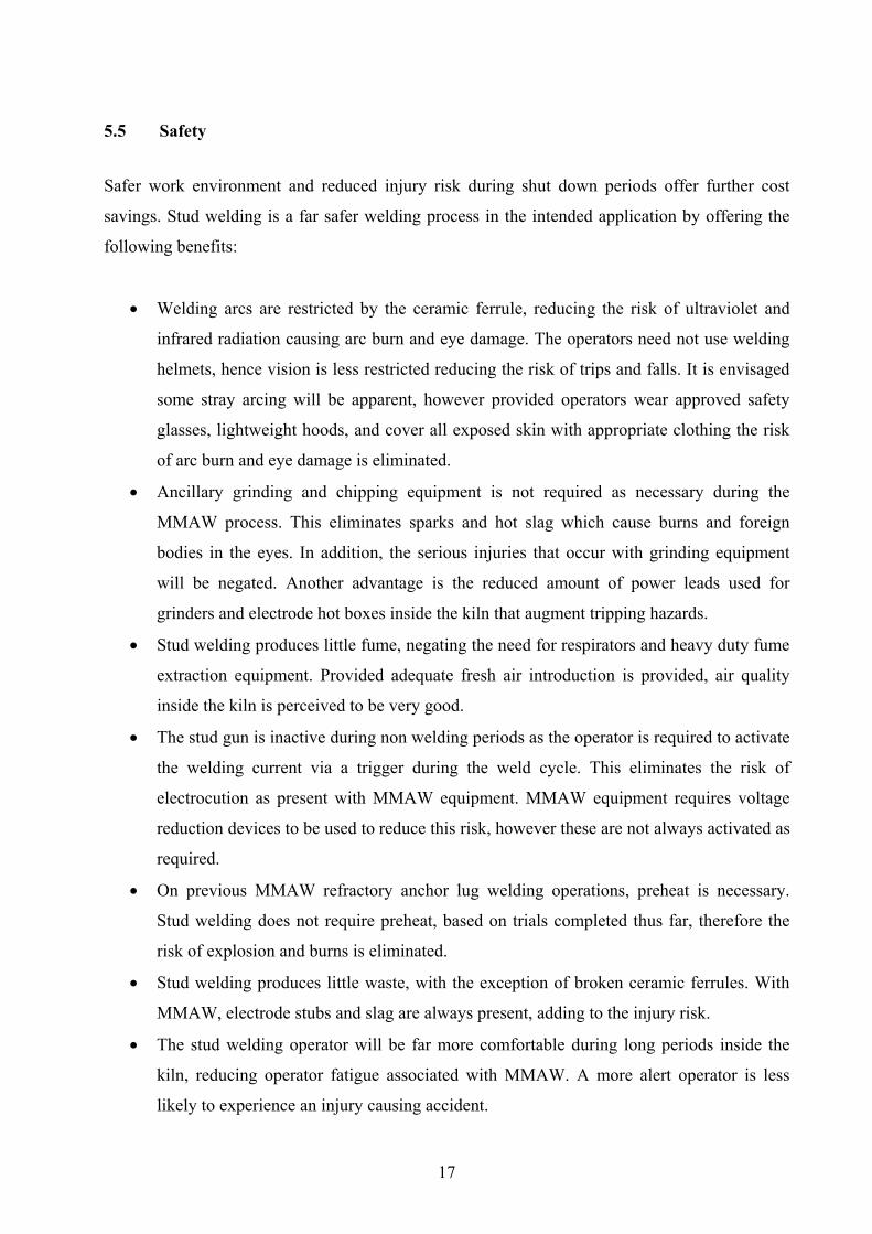
5.5 Safety
Safer work environment and reduced injury risk during shut down periods offer further cost
savings. Stud welding is a far safer welding process in the intended application by offering the
following benefits:
• Welding arcs are restricted by the ceramic ferrule, reducing the risk of ultraviolet and
infrared radiation causing arc burn and eye damage. The operators need not use welding
helmets, hence vision is less restricted reducing the risk of trips and falls. It is envisaged
some stray arcing will be apparent, however provided operators wear approved safety
glasses, lightweight hoods, and cover all exposed skin with appropriate clothing the risk
of arc burn and eye damage is eliminated.
• Ancillary grinding and chipping equipment is not required as necessary during the
MMAW process. This eliminates sparks and hot slag which cause burns and foreign
bodies in the eyes. In addition, the serious injuries that occur with grinding equipment
will be negated. Another advantage is the reduced amount of power leads used for
grinders and electrode hot boxes inside the kiln that augment tripping hazards.
• Stud welding produces little fume, negating the need for respirators and heavy duty fume
extraction equipment. Provided adequate fresh air introduction is provided, air quality
inside the kiln is perceived to be very good.
• The stud gun is inactive during non welding periods as the operator is required to activate
the welding current via a trigger during the weld cycle. This eliminates the risk of
electrocution as present with MMAW equipment. MMAW equipment requires voltage
reduction devices to be used to reduce this risk, however these are not always activated as
required.
• On previous MMAW refractory anchor lug welding operations, preheat is necessary.
Stud welding does not require preheat, based on trials completed thus far, therefore the
risk of explosion and burns is eliminated.
• Stud welding produces little waste, with the exception of broken ceramic ferrules. With
MMAW, electrode stubs and slag are always present, adding to the injury risk.
• The stud welding operator will be far more comfortable during long periods inside the
kiln, reducing operator fatigue associated with MMAW. A more alert operator is less
likely to experience an injury causing accident.
Page 33
18
6 STUD WELDING STANDARDS
6.1 Australian Standard AS/NZS: 1554 Part 2
AS/NZS: 1554. Part 2 is the welding standard for stud welding of steel studs to steel. This
standard provides details of qualified stud materials, application of the process, qualification of
welding procedures, pre-production testing, production testing and stud weld acceptance criteria.
Section 2 outlines details for the general requirements of stud design. This includes stud, ferrule,
flux, stud base and manufacturing requirements and restrictions. Clause 2.2 lists requirements
for the mechanical properties of the stud material and the procedures for testing. Tensile testing
is required as per Clause 2.2.2.2; a typical tensile test fixture is shown in Figure 6. The parent
material must comply with the requirements of Clause 2.3.
Section 3 details the stud application qualification requirement. Studs applied in the flat position
(i.e. less than 15° inclination) are deemed prequalified within the extent of the manufacturer’s
stud base qualification tests. Based on the welding trials conducted so far, this will not be
exceeded, however sensible welding procedure qualification based on manufacturer’s
qualification requirements will be completed due to the criticalness of the application intended,
regardless of the prequalified conditions of AS/NZS:1554 part 2. Stud manufacturers rarely
conduct the qualification requirements stated in this standard, therefore the onus is on the end
user to ensure the proposed stud base and substrate material is qualified in accordance with the
relevant sections of this standard prior to purchase.
Section 4 details the requirement for production weld testing. The procedures and requirements
for pre-production testing and production welding depend on whether or not the stud welding
power source records weld cycle parameters. Where the power source does not record
parameters, as is our case, the procedure for preproduction testing is as per clause 4.1.2 where
daily tests are required for the first two welded studs each day as per Clause 4.1.2.1. Once
production welding has begun, any changes as defined in Clause 4.1.2 shall require further pre-
production testing. Furthermore, all stud welding operators must comply with and are qualified
by the general and technical knowledge requirements as per Clause 4.3.
Page 34
19
Section 5 covers all aspects of production techniques and workmanship. This includes
preparations before welding and studs, stud bases, and parent materials have to be free from
deleterious materials. Ferrules shall be dry and recommendations for re drying ferrules is
provided. Welding technique must comply with that stated in Clause 5.2. This clause also
outlines alterations for welding in adverse weather and discusses options for alternative welding
processes and their requirements. Clause 5.3 places restrictions on minimum stud spacing and
finished weld treatment is covered in Clause 5.4. Clause 5.6.1.2 is specific to our stud welding
scenario and will be applied to all production and preproduction test studs as detailed earlier in
this report.
Section 6 of this standard details the testing of finished welds, in this case clause 6.1.2 in
particular, where equipment used does not record welding parameters.
Appendix C in AS/NZS: 1554 Part 2 details the requirement for stud manufacturers to qualify
the stud design and provides guidance for the stud manufacturer certification of a stud base for
welding under shop or field conditions. The standard outlines details for the following:
• Responsibility for tests
• Extent of qualification
• Duration of qualification
• Preparation of test specimens
• Number of test specimens
• Testing procedure
• Qualification requirements
• Retesting procedure
• Manufacturer’s qualification test report
In particular, clause C6.2 will be applied to in this case. The welded samples and testing regime
will be completed to qualify the stud welding procedures for the rotary kiln application.
6.2 Other relevant standard AWS D1.1-2006
A review of this standard has shown an overall similarity with AS/NZS: 1554 Part 2. Details
with regards to material qualification, applications, procedure and testing are virtually identical
Page 35
20
based on prequalified stud welding requirements. The manufacturer’s qualification requirements
will be completed as part of stud welding qualification to AWS D1.1, due to the critical nature of
the intended application. The following stud welded samples will be produced to satisfy the Stud
welding procedure and stud manufacturer qualification requirements to both applied stud
welding standards.:
1. 15 studs welded at optimum current / required time
2. 10 studs welded at 5% reduction in optimum current / required time
3. 10 studs welded at 5% above optimum current / required time
Stud samples in point 1 above welded at optimum current / required time subjected to 10 x
tensile tests to satisfy 3.3.3.2 in AS/NZS:1554 Part 2 and Annex G / G6 and G7 in AWS
D1.1and 5 x 90° bend along the original axis to satisfy 3.3.2 in AS/NZS:1554 Part 2
Stud samples in point 2 above welded at 5.0 % below optimum current / required time subjected
to 10 x tensile tests to satisfy Annex G / G7 in AWS D1.1
Stud samples in point 3 above welded at 5.0 % above optimum current / required time subjected
to10 x tensile tests to satisfy Annex G / G7 in AWS D1.1
In addition, other tests deemed relevant to the intended application will be completed. The full
mechanical and metallurgical test regime applied to the stud weld samples will be described later
in this report.
7 SUMMARY OF FEASIBILITY STUDY
The stud welding process as discussed above in sections one to six with regard to suitability for
rotary kiln refractory anchor attachment lugs appears promising. Calculations performed
demonstrate a 25mm diameter stud is required to achieve similar mechanical properties to those
of the MMAW welded lugs and that the final studs will meet or exceed current practice service
life.
Based on the information gathered and presented in this report, welding trials to directly compare
MMAW lugs to proposed stud welds have been conducted. The results reported for the
comparison trial welding samples are detailed and discussed in section 8 of this report.
Page 36
21
8 STUD WELD COMPARISON TRAIL WELDING
Utilising stud welding for the refractory anchor lug in rotary kilns appears feasible, and welding
trials were performed to evaluate the stud weld properties in comparison to current practices.
These welding trials will determine if the stud weld properties can be achieved on sections of
kiln shell material, and if results are favourable, qualification of a stud welding procedure for
future kiln refractory anchor lug replacement programmes.
The purpose of the stud welding trails was to compare two methods of attaching refractory
anchor lugs. Stud weld and heat affected zone properties, tensile properties and fatigue
performance were evaluated on the refractory attachment methods below:
1. Current method: 6mm fillet weld between AS: 1548-7-460R kiln shell plate and 40mm x
40mm x 10mm AS/NZS: 3679 Grade 300 flat bar.
2. Proposed method: AS: 1443 Grade D3 M1020 25mm OD stud incorporating grade 1100
H16 aluminium flux ball welded to AS 1548-7-460R kiln shell plate.
8.1 Sample description and evaluation test regime
A Perth based stud welding company, STUDCO, was contracted to weld the test samples.
Sections of rotary kiln shell and AS/NZS: 3679 Grade 300 anchor lugs were supplied by Iluka
Resources Limited.
Equipment for stud welding included a high output stud welding transformer delivering drooping
characteristic DC welding current and stud welding gun with a stud retaining chuck suited to a
25mm OD stud. The studs incorporated Grade 1100 H16 aluminium flux balls placed in a small
centre drilled hole at the stud base. The purpose of the flux ball is to tie up any impurities
including oxygen and nitrogen, and to refine the weldmetal grain size. 25mm ceramic ferrules
were used to control and contain the expelled flash material. The stud gun used for welding trials
was a Nelson P- NS 20 BHD heavy duty model, fitted with a chuck suitable for a 25mm OD
stud. The equipment planned for the welding trials is shown in figures 3 and 4 below:
Page 37
22
Prior to commencing the test samples, many studs were welded to scrap steel sections to
determine optimum parameters. Once confirmed, two studs were welded to a section of AS/NZS:
3678 Grade 350 plate to assess by bend test. In figure 7 below, the left stud did not exhibit a full
360° flash. The bend test on this stud placed the zone exhibiting no flash to tension. The fusion
between the stud and the base material was not affected, and it performed as well as the stud
exhibiting the full 360° flash. The parameters used during the stud welds were:
• Welding current: 1900 amps
• Polarity DCEN
• Weld cycle duration of 1.0 second.
• Lift of 4.0mm
• Plunge distance of 6.0mm
Figure 3 – Nelson 6000 power source Figure 4 – Nelson P-NS 20 BHD stud gun
Figure 5 – Stud samples and ferrules Figure 6 – Stud samples showing grade 1100 H16 aluminium flux ball.
Page 38
23
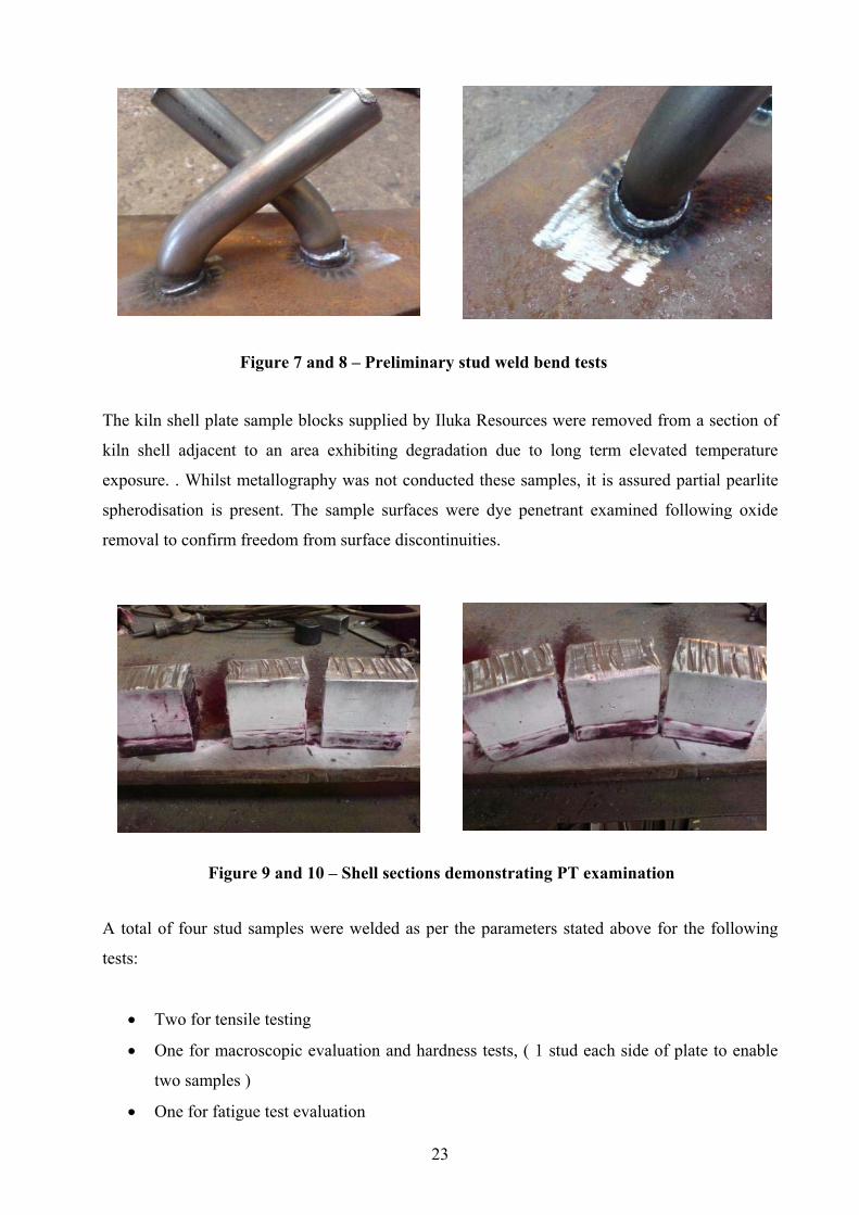
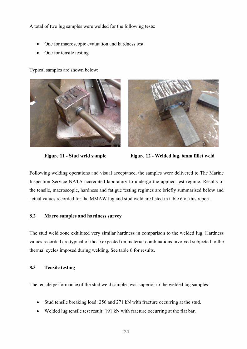
The kiln shell plate sample blocks supplied by Iluka Resources were removed from a section of
kiln shell adjacent to an area exhibiting degradation due to long term elevated temperature
exposure. . Whilst metallography was not conducted these samples, it is assured partial pearlite
spherodisation is present. The sample surfaces were dye penetrant examined following oxide
removal to confirm freedom from surface discontinuities.
A total of four stud samples were welded as per the parameters stated above for the following
tests:
• Two for tensile testing
• One for macroscopic evaluation and hardness tests, ( 1 stud each side of plate to enable
two samples )
• One for fatigue test evaluation
Figure 7 and 8 – Preliminary stud weld bend tests
Figure 9 and 10 – Shell sections demonstrating PT examination
Page 39
24
A total of two lug samples were welded for the following tests:
• One for macroscopic evaluation and hardness test
• One for tensile testing
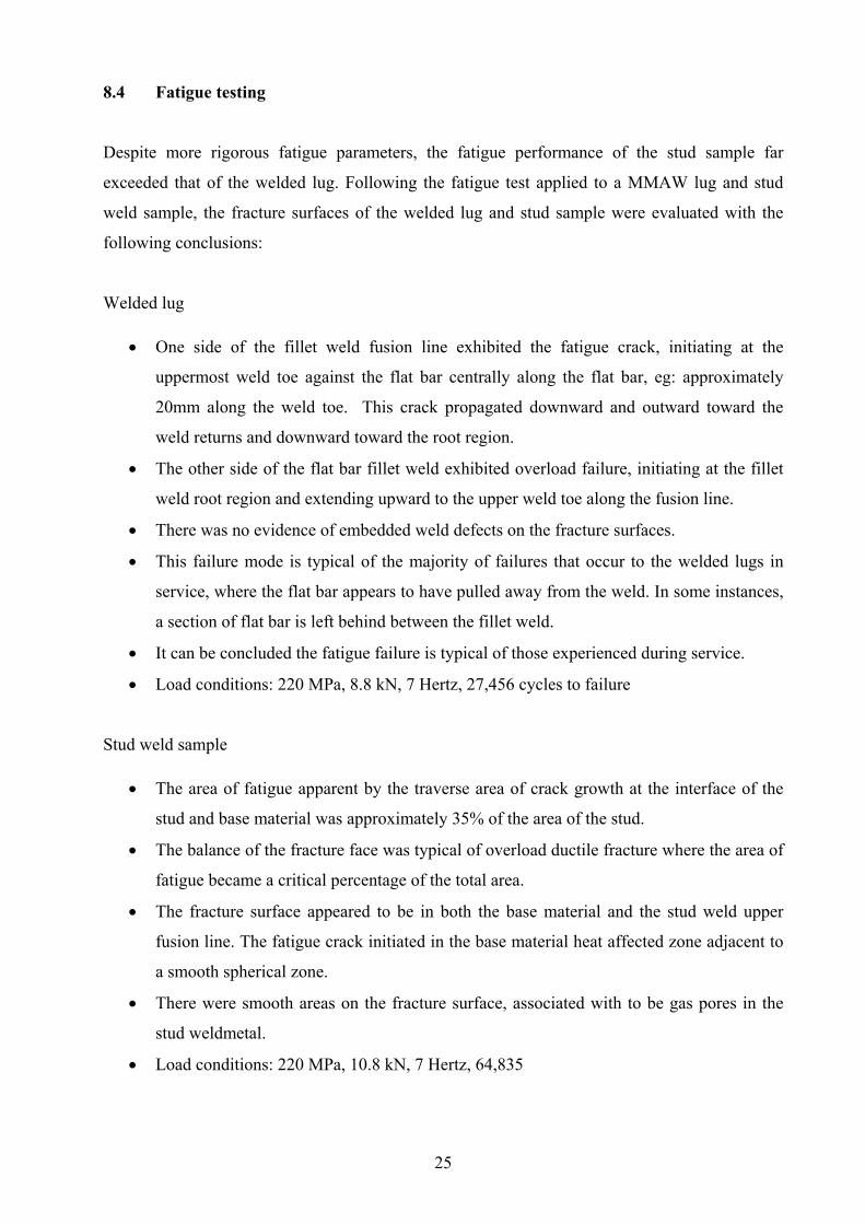
Typical samples are shown below:
Figure 11 - Stud weld sample Figure 12 - Welded lug, 6mm fillet weld
Following welding operations and visual acceptance, the samples were delivered to The Marine
Inspection Service NATA accredited laboratory to undergo the applied test regime. Results of
the tensile, macroscopic, hardness and fatigue testing regimes are briefly summarised below and
actual values recorded for the MMAW lug and stud weld are listed in table 6 of this report.
8.2 Macro samples and hardness survey
The stud weld zone exhibited very similar hardness in comparison to the welded lug. Hardness
values recorded are typical of those expected on material combinations involved subjected to the
thermal cycles imposed during welding. See table 6 for results.
8.3 Tensile testing
The tensile performance of the stud weld samples was superior to the welded lug samples:
• Stud tensile breaking load: 256 and 271 kN with fracture occurring at the stud.
• Welded lug tensile test result: 191 kN with fracture occurring at the flat bar.
Page 40
25
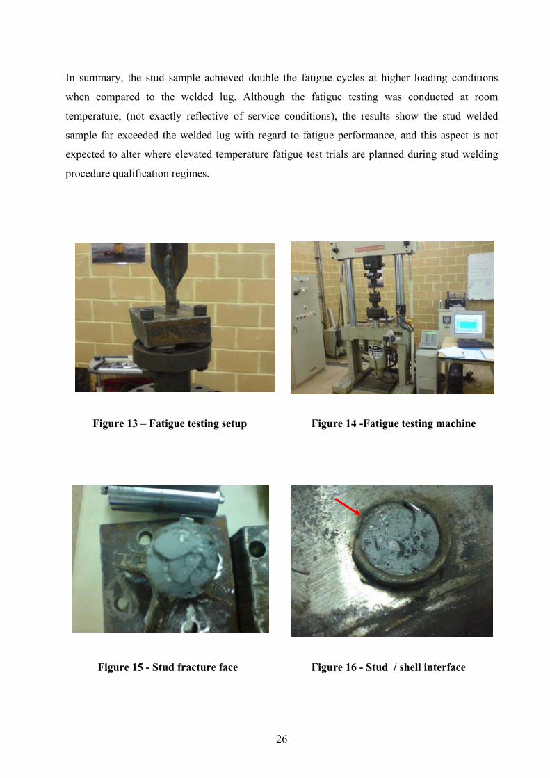
8.4 Fatigue testing
Despite more rigorous fatigue parameters, the fatigue performance of the stud sample far
exceeded that of the welded lug. Following the fatigue test applied to a MMAW lug and stud
weld sample, the fracture surfaces of the welded lug and stud sample were evaluated with the
following conclusions:
Welded lug
• One side of the fillet weld fusion line exhibited the fatigue crack, initiating at the
uppermost weld toe against the flat bar centrally along the flat bar, eg: approximately
20mm along the weld toe. This crack propagated downward and outward toward the
weld returns and downward toward the root region.
• The other side of the flat bar fillet weld exhibited overload failure, initiating at the fillet
weld root region and extending upward to the upper weld toe along the fusion line.
• There was no evidence of embedded weld defects on the fracture surfaces.
• This failure mode is typical of the majority of failures that occur to the welded lugs in
service, where the flat bar appears to have pulled away from the weld. In some instances,
a section of flat bar is left behind between the fillet weld.
• It can be concluded the fatigue failure is typical of those experienced during service.
• Load conditions: 220 MPa, 8.8 kN, 7 Hertz, 27,456 cycles to failure
Stud weld sample
• The area of fatigue apparent by the traverse area of crack growth at the interface of the
stud and base material was approximately 35% of the area of the stud.
• The balance of the fracture face was typical of overload ductile fracture where the area of
fatigue became a critical percentage of the total area.
• The fracture surface appeared to be in both the base material and the stud weld upper
fusion line. The fatigue crack initiated in the base material heat affected zone adjacent to
a smooth spherical zone.
• There were smooth areas on the fracture surface, associated with to be gas pores in the
stud weldmetal.
• Load conditions: 220 MPa, 10.8 kN, 7 Hertz, 64,835
Page 41
26
In summary, the stud sample achieved double the fatigue cycles at higher loading conditions
when compared to the welded lug. Although the fatigue testing was conducted at room
temperature, (not exactly reflective of service conditions), the results show the stud welded
sample far exceeded the welded lug with regard to fatigue performance, and this aspect is not
expected to alter where elevated temperature fatigue test trials are planned during stud welding
procedure qualification regimes.
Figure 13 – Fatigue testing setup Figure 14 -Fatigue testing machine
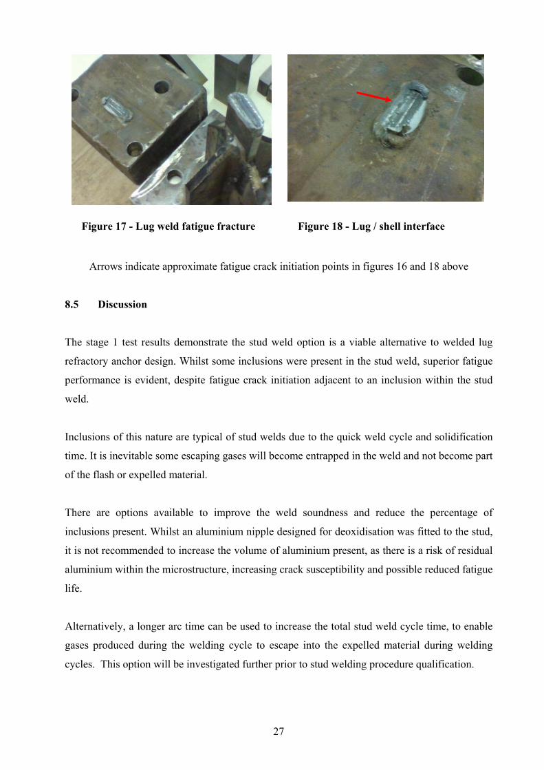
Figure 15 - Stud fracture face Figure 16 - Stud / shell interface
Page 42
27
Arrows indicate approximate fatigue crack initiation points in figures 16 and 18 above
8.5 Discussion
The stage 1 test results demonstrate the stud weld option is a viable alternative to welded lug
refractory anchor design. Whilst some inclusions were present in the stud weld, superior fatigue
performance is evident, despite fatigue crack initiation adjacent to an inclusion within the stud
weld.
Inclusions of this nature are typical of stud welds due to the quick weld cycle and solidification
time. It is inevitable some escaping gases will become entrapped in the weld and not become part
of the flash or expelled material.
There are options available to improve the weld soundness and reduce the percentage of
inclusions present. Whilst an aluminium nipple designed for deoxidisation was fitted to the stud,
it is not recommended to increase the volume of aluminium present, as there is a risk of residual
aluminium within the microstructure, increasing crack susceptibility and possible reduced fatigue
life.
Alternatively, a longer arc time can be used to increase the total stud weld cycle time, to enable
gases produced during the welding cycle to escape into the expelled material during welding
cycles. This option will be investigated further prior to stud welding procedure qualification.
Figure 17 - Lug weld fatigue fracture Figure 18 - Lug / shell interface
Page 43
28
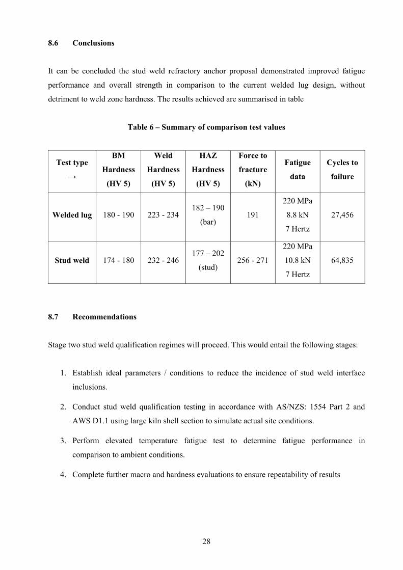
8.6 Conclusions
It can be concluded the stud weld refractory anchor proposal demonstrated improved fatigue
performance and overall strength in comparison to the current welded lug design, without
detriment to weld zone hardness. The results achieved are summarised in table
Table 6 – Summary of comparison test values
Test type
→
BM
Hardness
(HV 5)
Weld
Hardness
(HV 5)
HAZ
Hardness
(HV 5)
Force to
fracture
(kN)
Fatigue
data
Cycles to
failure
Welded lug 180 - 190 223 - 234 182 – 190
(bar) 191
220 MPa
8.8 kN
7 Hertz
27,456
Stud weld 174 - 180 232 - 246 177 – 202
(stud) 256 - 271
220 MPa
10.8 kN
7 Hertz
64,835
8.7 Recommendations
Stage two stud weld qualification regimes will proceed. This would entail the following stages:
1. Establish ideal parameters / conditions to reduce the incidence of stud weld interface
inclusions.
2. Conduct stud weld qualification testing in accordance with AS/NZS: 1554 Part 2 and
AWS D1.1 using large kiln shell section to simulate actual site conditions.
3. Perform elevated temperature fatigue test to determine fatigue performance in
comparison to ambient conditions.
4. Complete further macro and hardness evaluations to ensure repeatability of results
Page 44
29
9 STUD WELD QUALIFICATION
The qualification of stud welding to recognised welding standards has been performed. A large
section of rotary kiln shell was supplied by Iluka Resources and stud samples supplied by
STUDCO. The following welding standards were used as reference to determine stud
qualification requirements:
• AS / NZS 1554.2 2004 - Structural Steel Welding Part 2: Stud Welding
• AWS D1.1 2006 - Structural Welding Code Section 7: Stud Welding
Both the above standards allow stud welding prequalification status where the following
requirements are present or verified:
• The stud manufacturer’s qualification testing as described in Appendix C of AS/NZS:
1554 Part 2 and AWS D1.1-2006 is completed and verified as compliant.
• Base material to which the studs are to be welded complies with the materials listed in
clause 2.3 of AS/NZS: 1554 Part 2 or material groups I or II as per table 3.1 in AWS
D1.1. In this case, AS: 1548-7-460R is used for the kiln shell material and good
engineering judgement would group this material as group I.
• Stud base material complies with the requirements of AS: 1443 or ASTM A108 Grade
1010 or 1020. In this case AS: 1443 grade D3 M1020 is selected.
• Stud welding procedural controls in accordance with section 4 of AS/NZS: 1554 Part 2
are in place and documented.
• Studs are not welded through decking and surface coatings or in damp conditions.
• Studs are to be welded in a flat position within the range of 0° to 15°
The above requirements for pre qualification of stud welding are all valid for the application on
rotary kilns, however qualification of welding procedures will be performed based on the stud
base manufacturer’s qualification to both the referenced standards to ensure there is no doubt
regarding the weld quality, repeatability, mechanical performance and degree of reliability
required to assure adequate service performance.
9.1 Determination of optimum stud welding parameters
Prior to performing the welding procedure qualifications, further work was undertaken to
determine optimum settings. The values used during initial comparison trials were:
Page 45
30
• Welding current: 1900 amps. Polarity DCEN
• Weld cycle duration of 1.0 second.
• Lift of 4.0mm. Plunge distance of 6.0mm
The aim of determining optimum current settings is to reduce the presence of gas pores and
inclusions within the stud weld. Based on results obtained during the initial comparison trails, it
is evident we are very close to optimum settings based on the above values. Below is a summary
of results obtained using macro specimens to determine the presence of inclusions or gas pores.
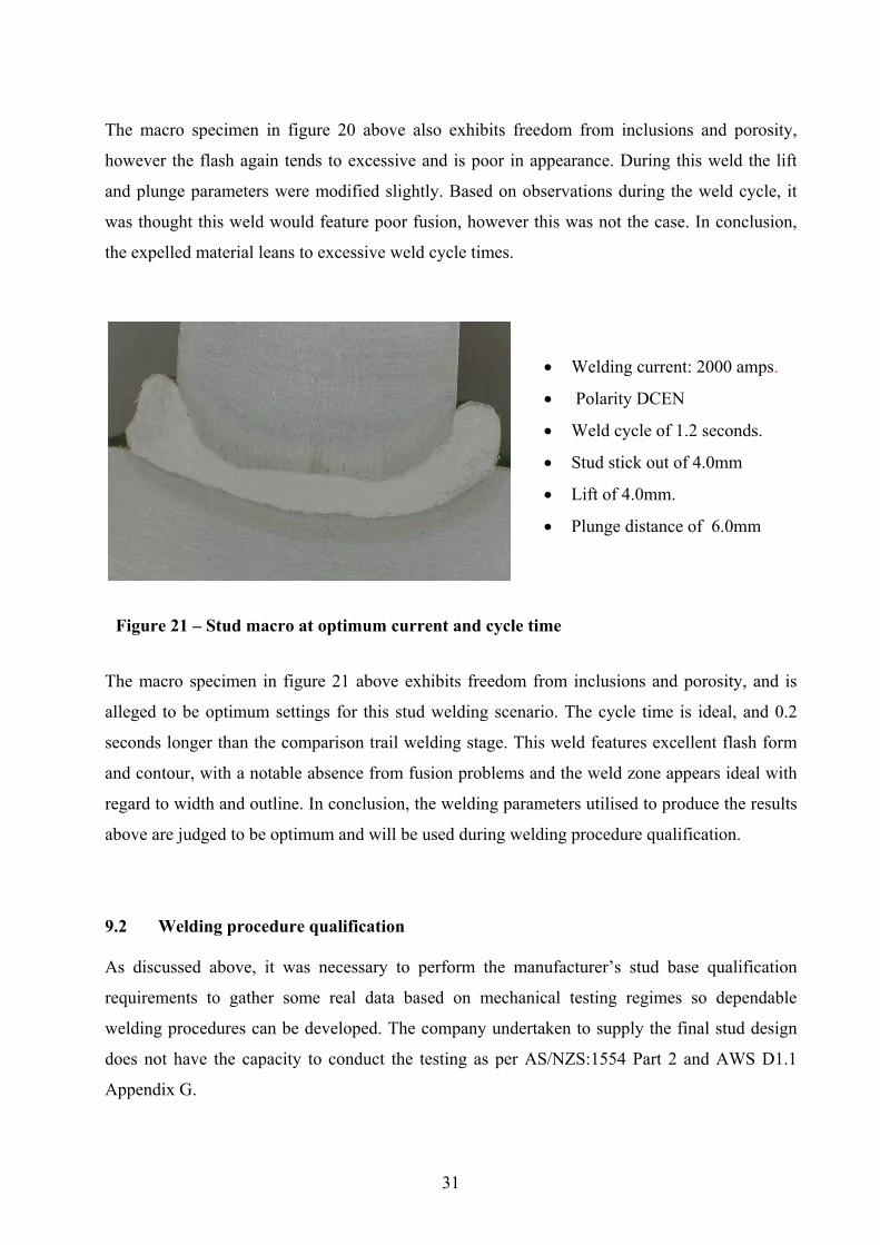
The macro specimen in figure 19 above exhibits freedom from inclusions and porosity, however
the flash tends to excessive and is poor in appearance. During this weld it was apparent the cycle
time was excessive, as an increased percentage of spatter. In addition, the sound produced during
the weld cycle gave the impression of excess current.
Figure 19 – Stud macro at higher current and cycle time
• Welding current: 2100 amps.
• Polarity DCEN
• Weld cycle of 1.5 seconds.
• Lift of 4.0mm.
• Plunge distance of 6.0mm
• Welding current: 1900 amps.
• Polarity DCEN
• Weld cycle of 1.5 seconds.
• Lift of 3.0mm.
• Plunge distance of 4.0mm
Figure 20 – Stud macro at lower current and cycle time, with modified lift / plunge data
Page 46
31
The macro specimen in figure 20 above also exhibits freedom from inclusions and porosity,
however the flash again tends to excessive and is poor in appearance. During this weld the lift
and plunge parameters were modified slightly. Based on observations during the weld cycle, it
was thought this weld would feature poor fusion, however this was not the case. In conclusion,
the expelled material leans to excessive weld cycle times.
The macro specimen in figure 21 above exhibits freedom from inclusions and porosity, and is
alleged to be optimum settings for this stud welding scenario. The cycle time is ideal, and 0.2
seconds longer than the comparison trail welding stage. This weld features excellent flash form
and contour, with a notable absence from fusion problems and the weld zone appears ideal with
regard to width and outline. In conclusion, the welding parameters utilised to produce the results
above are judged to be optimum and will be used during welding procedure qualification.
9.2 Welding procedure qualification As discussed above, it was necessary to perform the manufacturer’s stud base qualification
requirements to gather some real data based on mechanical testing regimes so dependable
welding procedures can be developed. The company undertaken to supply the final stud design
does not have the capacity to conduct the testing as per AS/NZS:1554 Part 2 and AWS D1.1
Appendix G.
• Welding current: 2000 amps.
• Polarity DCEN
• Weld cycle of 1.2 seconds.
• Stud stick out of 4.0mm
• Lift of 4.0mm.
• Plunge distance of 6.0mm
Figure 21 – Stud macro at optimum current and cycle time
Page 47
32
9.3 Base materials
The base materials used for procedure qualification consisted of a 3.0m x 1.5m x 90mm thick
section of AS:1548-7-460R removed from a discarded strake cut from the kiln.. The heat
number is unknown due to the lack of material certificates available from Iluka traceable to that
particular section. The stud samples were 150mm x 25mm diameter AS: 1443 grade D3 M1020
carbon steel bright finished bar, heat number: 601348. Other consumable items included the
grade 1100 H16 aluminium flux ball and AF-1”F ceramic ferrule.
The section of base material in figure 22 above was marked out to ensure the welded stud
samples could be removed with enough base material to allow mechanical testing. Figure 23
below is a STUDCO employee removing the oxide layer at each weld zone where stud welds
will be applied.
Figure 22 – Kiln shell section
marked out for stud welding
Figure 23 – Weld zone
oxide removal
Page 48
33
9.4 Welded stud samples A total of 42 studs were welded for welding procedure qualification purposes and simulation of
worst case site conditions.. In addition two test studs were welded prior to commencing the
official qualification studs to simulate the daily test regime. Both these studs were bent 90° to
the base plate, with no apparent defects highlighted.
Each stud was welded at 125mm centres to allow a square sample of base plate to be removed,
producing 42 separate samples suited to the mechanical testing regimes planned. Each stud was
clearly marked with the allocated identification number.
This stage of work simulated actual site conditions which enabled stud weld cycle times to be
recorded to assemble some real data so site welding scenarios can be accurately predicted. The
stud welding procedure qualification operation was witnessed by representatives from Iluka
Resources, the proposed stud manufacturer and the author. A short movie was recorded during
the stud welding process, and is included with this dissertation on a compact disc.
9.5 Stud traceability information
1. 17 stud samples A1 to A17 welded at optimum settings and time
2. 11 stud samples B1 to B11 welded at 5.0 % below optimum current settings using
optimum time.
3. 11 stud samples C1 to C11 welded at 5.0 % above optimum current settings using
optimum time.
4. Stud sample D1 was welded onto an oxide covered uneven surface of the base plate at a
location where a welded lug had been previously removed. Also we simulated the worst
case conditions involving failed arc start and restart using the same stud.
5. Stud sample D2 was welded onto bright metal incorporating an uneven surface. The
location was ground to bright metal with a 4.0mm deviation present at the base material
surface at the stud weld zone.
6. Stud sample D3 was welded onto an oxide contaminated flat surface of base material.
This would simulate an area of kiln shell in production exhibiting poor preparation with
regard to oxide removal.
Page 49
34
Figure 24 – Stud sample test plate during welding
Figure 25 – Completed test plate
A1-A17
B1-B11
C1-C11
D1
D2
D3
Page 50
35
Figure 26 – Close up of stud sample A6
Figure 27 – Close up of stud sample B6
Figure 28 – Close up of stud sample B8
Page 51
36
9.8 Results of tensile testing and bend samples. The stud samples were individually cut out using a profile cutting machine and delivered to
Amdel for evaluation. The tables below detail the results from the testing regime applied to
qualify the stud welds based on the manufacturer’s stud base qualification in accordance with
AS/NZS: 1554 Part 2 and AWS D1.1.
9.6 Samples to qualify the applied welding standards 1 - Studs welded at optimum current and time. Stud samples A1 to A15
• 10 x tensile tests
• 5 x 90° bend along the original axis.
2 - Studs welded at 5% below optimum current and optimum time. Stud samples B1 to B10
• 10 x tensile tests
3 - Studs welded at 5% above optimum current and required time. Stud samples C1 to C11
• 10 x tensile tests
9.7 Additional test regime 1 – Macro and HV10 survey to weldmetal, heat affected zone and base material.
• Stud samples A16 / B11 / C11, representative of each current setting used under
optimum surface conditions.
2 – Macro to determine stud to base material interface where less than optimum surface
conditions are present prior to welding the stud.
• Stud samples D1 / D2 / D3
3 – Elevated temperature fatigue test at 300°C along the stud axis, at the following parameters:
10 kN force applying approximately 220 MPa stress at 8 to 10 cycles per second. This
will be for information only, to determine any reduction in fatigue performance compared
to the ambient fatigue test performed during the initial comparison stud welding trials.
• Stud sample A17
Page 52
37
Table 7 – Summary of tensile tests welded at optimum current
Sample Number UTS ( kN ) Comments
A1 256.0 Failed in stud
A2 252.4 Failed in stud
A3 247.0 Failed in stud
A4 254.9 Failed in stud
A5 256.8 Failed in stud
A6 253.5 Failed in stud
A7 255.7 Failed in stud
A8 260.2 Failed in stud
A9 248.6 Failed in stud
A10 254.1 Failed in stud
Table 8 – Summary of tensile tests welded 5% below optimum current
Sample Number UTS ( kN ) Comments
B1 263.0 Failed in stud
B2 250.6 Failed in stud
B3 248.0 Failed in stud
B4 251.0 Failed in stud
B5 252.7 Failed in stud
B6 253.8 Failed in stud
B7 256.6 Failed in stud
B8 252.7 Failed in stud
B9 247.2 Failed in stud
B10 258.3 Failed in stud
Page 53
38
Table 9 – Summary of tensile tests welded 5% above optimum current
Sample Number UTS ( kN ) Comments
C1 260.6 Failed in stud
C2 260.7 Failed in stud
C3 252.9 Failed in stud
C4 248.4 Failed in stud
C5 258.7 Failed in stud
C6 249.9 Failed in stud
C7 248.0 Failed in stud
C8 254.3 Failed in stud
C9 256.5 Failed in stud
C10 251.3 Failed in stud
Figure 29 – Stud sample tensile test setup
Page 54
39
Table 10 – Summary of bend tests at optimum current
Sample Number Test Comments
A11 90° bend Passed – No disbondment
A12 90° bend Passed – No disbondment
A13 90° bend Passed – No disbondment
A14 90° bend Passed – No disbondment
A15 90° bend Passed – No disbondment
Figure 30 / 31 – Typical necking and stud failure
Figure 32 / 33 – Typical bending sample
Page 55
40
9.9 Results of hardness testing using Vickers pyramid tester ( HV 10 )
The values recorded during the mechanical test regime and detailed in tables 7, 8, 9 and 10 above
satisfy the requirements for tensile and bend testing in the applied welding standards. In addition
to the welding standard stud manufacturer’s requirements, further tests were completed. These
included hardness testing to stud welds within the acceptable range of parameters and elevated
temperature fatigue testing to compare the results achieved in contrast to those reported for
fatigue testing completed at room temperature.
Table 11 – Summary of typical hardness testing within welding current range
Traverse 1 HV 10 Traverse 2 HV 10 Traverse 3 HV 10
187.5 176.8 176.6
179.4 184.4 180.4 Base material
183.1
Base material
193.8
Base material
182.2
209.5 208.8 199.6
238.7 252.1 215.2
296.7 309.7 239.3
Base material
HAZ
320.2
Base material
HAZ / FL
287.7
Base material
HAZ
258.9
275.5 226.4 321.7
280.5 221.6 245.0
289.5 187.0 231.8 Weld
244.0
Weld FL
Stud HAZ
172.4
Weld
208.0
199.2 168.8 184.7
182.1 168.0 184.3
162.9 172.9 169.2 Stud HAZ
166.4
Stud
Base material
-
Stud HAZ
167.5
162.7 - - 165.7
194.2 - - 173.7
181.3 - - 178.6
Stud
Base material
176.1 - -
Stud
Base material
185.0
Page 56
41
Macro samples to determine weld zone fusion where worst case scenarios incorporating heavy
oxidisation, uneven surfaces, stud refiring and where welded lugs had been removed were
completed. Under all these conditions, excellent fusion was achieved in all cases. This proves the
stud welding process can tolerate all these less than ideal surface conditions.
During production, the weld zone location will be ground flat to bright metal, however
deviations in contact area between the base material and stud are likely in some cases. The
observations made to macro sections representative of this condition, and conditions far worse
provide a degree of comfort that the resultant stud weld is sound and typical of those welded
under ideal surface conditions.
9.10 Results of elevated temperature fatigue test. Stud sample A17 was subject to an elevated temperature fatigue test at 300°C to compare results
with those obtained for the ambient temperature fatigue test. It was decided to machine a sample
from the stud, as the autoclave fitted to the fatigue testing machine would not accommodate the
standard stud to base plate configuration.
The machined sample did not exhibit the stress concentrations present on the ambient sample,
however metallurgical notches were present where the stud HAZ, weld admixture, and base
Figure 34 – Typical macro sample incorporating HV10 survey welded within acceptable parameter ranges
Page 57
42
material HAZ are considered. The same fatigue load parameters were applied and are
summarised in table 12 below.
Table 12 – Summary of elevated temperature fatigue test parameters
Test
temperature
Applied
force
Resultant
stress
Cycles per
second
Duration
of test
Cycles
applied Results
300°C 8 to 10 kN 220 MPa 8 Hz 24 hours 350,000
Approx
No
failure
reported
The above sample was expected to outperform the ambient temperature fatigue sample which
failed at approximately 65,000 cycles, however there was no fatigue failure in the elevated
temperature sample assessed. It is assumed the absence of stress concentrations on the test
sample contributed to the values reported. Due to cost constraints, the elevated temperature
fatigue test was abandoned following 24 hours.
In addition to the sample design, detailed in figure 36 below, the optimised stud welding
parameters have resulted in freedom from weld porosity, hence improved fatigue performance.
The fatigue crack initiation point on the ambient temperature sample was located at an inclusion
within the weld. Based on the values reported, it can be concluded the fatigue performance of the
stud weld is not adversely affected by temperatures up to 300°C.
Figure 35 – Elevated fatigue test setup
300°C autoclave
Page 58
43
9.11 Results of metallography to typical stud weld samples.
Stud sample A16, (as shown in figure 34 above), was subject to metallography to determine the
microstructure present across the welded zone including the base materials. The sample was
prepared using silicon carbide paper to a P1200 finish, polished using diamond paste to 0.25 µm
finish and etched using a 2% nital solution. The samples were evaluated at 100 times
magnification using a metallurgical microscope. The following features in each microstructure
were observed:
Stud base material – The microstructure exhibited equiaxed grains of ferrite and pearlite. The
percentage of pearlite was in the vicinity of 20%, typical of that expected with carbon,
manganese steel containing 0.2% carbon. A photo of the microstructure in this region is
presented in figure 37 below.
Stud heat affected zone, (HAZ) – The microstructure exhibited grain boundary ferrite in a matrix
of finely distributed pearlite. A percentage of the ferrite exhibited a widmanstatten morphology,
typical in weld microstructures where rapid thermal cycles occur. (It is interesting that this ferrite
feature is also present in meteorites which experience a similar thermal cycle). The pearlite
appeared degraded, suggesting a rapid thermal cycle where not enough time is available to form
the typical plate like appearance. A photo of the microstructure in this region is presented in
figure 38 below.
Figure 36 – Elevated fatigue test sample
Stud
Weld
Base
Page 59
44
Weld zone – The microstructure exhibited ferrite in a matrix of pearlite. The ferrite exhibited a
side plate morphology, interspersed amongst the pearlite. The pearlite again appeared degraded,
without the typical layered appearance. The weldmetal created by an admixture of both base
materials had more pearlite than expected. This is assumed due to the elevated percentage of
carbon in the weld zone as opposed to typical low carbon, ( < 0.02% ), weldmetal produced
using conventional fusion welding techniques. In summary, the overall microstructure exhibited
a columnar appearance, typical of weldmetal. A photo of the microstructure in this region is
presented in figure 39 below.
Base material heat affected zone – This microstructure was very interesting to observe,
incorporating at least four phases. In general, it consisted of ferrite and pearlite, combined with
small regions of acicular bainite and tempered martensite. The overall microstructure is typical
of the fast cooling rates associated with stud welding. Whilst very small isolated regions of
martensite are present, this is normal for welded heat affected zones, and is not considered
detrimental. A photo of the microstructure in this region is presented in figure 40 below.
Plate base material – This microstructure consisted of equiaxed grains of ferrite and pearlite with
a distinct banded appearance. These bands are typical of “as rolled” plates, where as cast
agglomerations of pearlite and ferrite are stretched out and flattened as a result of hot rolling
operations. Some of the pearlite appeared to be degraded, assumed to be spherodised due to
prolonged periods at elevated temperature during service as a kiln shell section. A photo of the
microstructure in this region is presented in figure 41 below.
Figure 37 – Stud base material micrograph
Page 60
45
Figure 38 – Stud HAZ micrograph
Figure 39 – Weld zone micrograph
Figure 40 – Plate HAZ micrograph
Page 61
46
9.12 Conclusions Following the mechanical and metallurgical testing regimes applied to the stud welding
qualification samples, it can be concluded the stud welds exhibit mechanical properties
exceeding the standard attachment method utilising MMAW welded lugs.
The microstructures reported for the stud welds reveal no serious deleterious phases, and are
typical of those expected for the base materials following the thermal cycles applied during
welding operations and the samples tested reflect the materials of construction.
Based on the information gathered, the author is certain the stud welding proposal can be used as
an alternative method for attachment of refractory anchors in rotary kilns and provide reliable
service under the conditions imposed.
If the stud welding proposal is adopted, there are significant savings to owners and operators of
rotary kilns by reducing the costly shut down periods where refractory anchors require
replacement, and eliminating service failures associated with MMAW lug refractory anchor
attachments.
Figure 41 – Plate base material micrograph
Page 62
47
10 FINALISED STUD DESIGN
The final design of the stud is based on the welded flat bar model in principle. With the current
welded flat bar design as shown earlier in this report, ( Figure 1 ), the 10mm diameter 253MA
stainless steel anchor is threaded through the 12mm diameter x 20mm long slotted hole and
stood up to lock against the flat bar. This is necessary, to lock the anchor in the upright position
and prevent movement during refractory pouring. There are two options available for the stud
end to refect the welded lug and anchor assembly.
Design of the studs for the rotary kiln application is at the prototype stage, with final design
confirmed once simple test regimes demonstrate the studs outperform the welded lug utilising a
pull out test using the 253MA stainless steel anchor. At this point in time, option 2 looks most
favourable, as it is preferred not to alter the design of the 253MA stainless steel anchor.
Figure 42 – Original AS/NZS: 3679 Grade 300 lug design
Page 63
48
10.1 Option 1 stud design
The first option involves machining a small face at the end of the stud and drilling a hole to
accept the 253MA stainless steel anchor. The current 253MA anchor design needs to be altered
to enable fitment through the drilled hole as opposed to the current slotted hole. Whilst this is a
feasible and simple stud design method, it is preferred not to change the design of the 253MA
stainless steel anchor.
10.2 Option 2 stud design
The second option involves a hot forming operation the produce a flat face on the end of the
stud, incorporating a slotted hole. This design facilitates the use of the current design 253MA
stainless steel anchor and is the preferred option. The flattened end and slotted hole can be
produced in one stage using a press incorporating a suitable die. The slotted hole does not need
to be 20mm long to facilitate the fitment of the current design 253MA anchor, and is therefore
reduced to 12mm diameter x 16mm long.
Figure 43 – Option 1 stud design
Page 64
49
10.3 Proposed test regimes for final stud design
Design of the studs is at the prototype stage, with final design confirmed once simple test
regimes demonstrate the studs outperform the welded with regard to a pull out test using the
253MA stainless steel anchor. This involves assembling the stud and anchor in a tensile testing
machine and testing to destruction. The perceived outcome is the 235MA stainless steel anchor
will elongate and fracture without any deformation occurring in the stud.
In addition to the pull out test described, metallography is planned to determine the final
microstructure following hot forming operations. Heat treatment is not planned, and the hot
forming procedure will facilitate a normalised structure in the deformed region.
Figure 44 – Option 2 stud design
Page 65
50
11 PLANNED APPLICATION TO ROTARY KILNS
Iluka Resources Limited have undertaken to trial the stud welding proposal to a section of rotary
kiln at the earliest possible convenience during a shut down period where remedial refractory
operations are planned. A ten metre section at the end of the rotary kiln where the highest service
temperatures are present is the proposed section where the studs that support the refractory
anchor will be applied. It is in this region where the majority of welded lug service failures have
occurred in the past. This region represents the worst service conditions and will be a good test
for the studs to determine the success of the project. It is unfortunate the production application
of the studs inside the rotary kiln is not scheduled until the second half of 2008, however a
production and serviceability report for the stud refractory anchor supports will be prepared and
incorporated as separate dissertation volume in future.
11.1 Welding procedure
A welding procedure in accordance with AS/NZS:1554 Part 2 and AWS D1.1 has been
developed based on the mechanical testing regime applied to the qualification samples and
applying the welding data recorded during the stud weld procedure qualification regime.
The welding procedure assures production welding is completed under controlled conditions and
studs welded in accordance with the instructions provided will provide reliable service. It is
important the welding procedure conveys all the vital operational data clearly and concisely, in a
format that is easily understood. The following information is documented within the procedure:
• Applicable welding standards
• Base material data and thickness ranges
• Equipment and consumables
• Consumable husbandry
• Weld joint details and preparation
• Stud welding parameters
• Daily and production testing regimes
• Stud weld visual and test requirements
• Remedial instructions for non complying studs
• Approvals
Page 66
51
STUD WELDING PROCEDURE QUALIFICATION & INSTRUCTION WPS No SW-0100
Rev 0 PQR No IR-0100 Rev 0
Code AS/NZS:1554 Part 2 AWS D1.1 Stud material AS:1443 Grade 1020
Process Drawn arc stud welding DSAW Stud dimensions 25mm diameter
Joint type Stud weld Base material AS:1548-7-460R
Position Flat ( 0° to 10° ) Thickness range 32mm to 90mm THERMAL CONDITIONS EQUIPMENT / CONSUMABLES Preheat If < 10°C preheat to 50°C Power source Nelson 6000
Method LPG / Air torch Stud gun Nelson P-NS 20 BHD
Check method Calibrated pyrometer Flux type Aluminium 1100 H16
Check distance 75mm from weld zone Ferrule type Ceramic AF-1” F
STUD HUSBANDRY FERRULE HUSBANDRY Studs shall be free from moisture rust, oils and other deleterious materials and stored in a suitable container at all times.
Ferrule shall be clean and dry. If moisture absorption is suspected, bake at 350°C for 2 hours
JOINT DETAILS WELD DETAIL
WELDING PARAMETERS CURRENT POLARITY STICK OUT LIFT PLUNGE TIME
Optimum < 5 % 1900 Amps
Optimum 2000 Amps
Optimum > 5 % 2100 Amps
DCEN 4.0mm 4.0mm 6.0mm 1.2 secs
STUD WELD QUALITY CONTROL REGIME 1. Prior to the commencement of every production shift, 2 studs shall be welded at 5% below and 2 studs 5%
above optimum current using weld cycle time of 1.2 seconds on representative base material within + / - 25% of the production thickness.
2. These studs shall exhibit 360° flash and pass an ambient temperature bend test at 45° from the original axis without any sign of disbondment.
3. The above QC regime shall be repeated at the commencement of each shift and following every 250 studs welded during any production run.
4. Production welded studs shall be welded within 10° of bottom dead centre and upon completion, 100% visually inspected to confirm 360° flash and hammer tested. Non conforming studs shall be removed using grinding methods and rewelded
5. Stud weld locations shall be ground to bright metal, free from oxide and other deleterious material.
Approved fabricator Release Stamp Approved Client Approve stamp
Page 67
52
12 FINITE ELEMENT ANALYSIS MODELS
Autodesk Inventor Professional Stress Analysis was used to simulate the behaviour of the stud
under structural loading conditions of compression, tension and bending moment. An evaluation
version of ANSYS software, made available by the University of Wollongong, generated the
results presented in this report. Additional information for Autodesk Inventor Professional Stress
Analysis and ANSYS products is available at http://www.ansys.com/autodesk.
The outcomes calculated are not a sole basis to accept or reject the design based solely on the
data presented in the tables below. Evaluation of the stud considers the information gathered
using FEA models in conjunction with practical test data. The general approach to any
engineering design usually applies engineering calculations and additional physical testing based
on actual production mock ups as the final means of verifying structural integrity.
12.1 Geometry and Mesh
The relevance setting listed below controlled the fineness of the mesh used for the FEA models.
For reference, a setting of -100 produces a coarse mesh, fast solutions and results that may result
in significant uncertainty. A setting of +100 generates a fine mesh, longer solution times and the
least uncertainty in results. Zero is the default Relevance setting and was applied in this case.
Bounding box dimensions represent lengths in the global X, Y and Z directions.
Table 13 – Stud and FEA model statistics
Stud mass and volume is inclusive of flash material incorporating a percentage of base material,
and is as calculated by the ANSYS program. Stud volume and mass alone is 1.809e+004 mm³
and 0.142 kg respectively.
Bounding Box Dimensions 25.0 mm , 25.0 mm, 40.0 mm Stud Mass 0.153 kg Stud Volume 1.949e+004 mm³ Mesh Relevance Setting 0 Nodes 8926 Elements 1950
Page 68
53
12.2 Material Data
The following material properties apply to this analysis:
• Linear - Stress is directly proportional to strain.
• Constant - All properties are temperature independent.
• Homogeneous - Properties do not change throughout the part.
• Isotropic - Material properties are identical in all directions.
Table 14 – Stud material statistics
12.3 Loads and constraints for compressive, tensile and bending forces
The following loads and constraints act on specific regions of the stud based on a 30 MPa
compressive, tensile and bending load. Vector data corresponds to X, Y and Z components.
Table 15 – Load and Constraint definitions
Table 16 – Constraint reactions
Young's Modulus 2.1e+005 MPa Poisson's Ratio 0.30 Mass Density 7.85e-006 kg/mm³ Tensile Yield Strength 380.0 MPa Tensile Ultimate Strength 480.0 MPa
Name Type Magnitude Vector
Force Surface force 3.e+007 N 0.00 N 0.00 N -3.e+007 N
Fixed constraint Edge fixed constraint 0.00 mm
0.00 mm 0.00 mm 0.00 mm
Name Force Vector Moment Moment Vector Fixed Constraint Compression
3.e+007 N 8.481e-003 N 3.632e-002 N 3.e+007 N
0.9375 N/mm -0.7583 N/mm -0.4625 N/mm -0.3 N/mm
Fixed Constraint Tensile
3.e+007 N -2.295e-002 N -3.693e-002 N -3.e+007 N
2.01 N/mm -1.155 N/mm -1.556 N/mm -0.5353 N/mm
Fixed Constraint Bending
3.e+007 N -0.1265 N 3.e+007 N 0.1024 N
1.14e+009 N/mm -1.14e+009 N/mm -3.611 N/mm -0.3703 N/mm
Page 69
54
12.4 Results
Table 16 below lists all structural results generated by the FEA analysis. Safety factor was
calculated by using the maximum equivalent stress failure theory for ductile materials calculated
by the ANSYS software. The stress limitation is determined by the yield and ensile and strength
of the material. Vector data corresponds to X, Y and Z components.
Table 17 – Analysis results - Compression
Table 18 – Analysis results - Tensile
Table 19 – Analysis results - Bending
12.5 FEA contour figures
The following section provides figures showing each load outcome contoured over the surface of
the stud.
Name Minimum Maximum
Equivalent Stress 2980 MPa 7.767e+005 MPa Maximum Principal Stress -3.98e+004 MPa 1.923e+005 MPa Minimum Principal Stress -8.999e+005 MPa 7092 MPa Deformation 0.00 mm 18.59 mm Safety Factor 2.665e-004 N/A
Name Minimum Maximum
Equivalent Stress 2791 MPa 9.987e+005 MPa Maximum Principal Stress -6467 MPa 1.159e+006 MPa Minimum Principal Stress -2.318e+005 MPa 5.031e+004 MPa Deformation 0.00 mm 19.08 mm Safety Factor 2.073e-004 N/A
Name Minimum Maximum
Equivalent Stress 3367 MPa 4.747e+006 MPa Maximum Principal Stress -1.922e+005 MPa 5.236e+006 MPa Minimum Principal Stress -4.782e+006 MPa 2.e+005 MPa Deformation 0.00 mm 283.8 mm Safety Factor 4.361e-005 N/A
Page 70
55
Figure 45 Deformation compression
Figure 46 Deformation tension
Figure 47 Deformation bending
Page 71
56
Figure 48 Equivalent stress
Compression
Figure 49 Equivalent stress
Tension
Figure 50 Equivalent stress
Bending
Page 72
57
Figure 51 Maximum principle stress
Compression
Figure 52 Maximum principle stress
Tension
Figure 53 Maximum principle stress
Bending
Page 73
58
Figure 54 Minimum principle stress
Compression
Figure 55 Minimum principle stress
Tension
Figure 56 Minimum principle stress
Bending
Page 74
59
Figure 57 Safety factor Compression
Figure 58 Safety factor
Tension
Figure 59 Safety factor
Bending
Page 75
60
Bibliography and list of references
The following Australian and international standards were referenced and researched to assist
with the development of this dissertation. Table numbers within these standards are referenced in
the dissertation table headings.
AS:1443 – 2004: Carbon and carbon manganese steel – Cold finished bars
AS/NZS:1554: 1: 2004: Structural steel welding – Welding of steel structures
AS/NZS:1554: 2: 2003: Structural steel welding Part 2: Stud welding (steel studs to steel)
AWS D1.1: 2006 – Structural welding code – steel
AS: 1210: 97 – Pressure vessels
AS/NZS:3679-1:1996 – Structural steel - Hot-rolled bars and sections
AS: 1548 – 2008: Fine grain weldable steel plates for pressure equipment
AS: 4100: 1998 – Steel structures
The following test laboratories assisted in compiling mechanical test values and metallurgical
data:
The Marine Inspection service – Mr Jeff Cook
Exceed Consulting – Mr Jeff Dunning
Amdel Testing – Mr Monty Luke
Software used to generate FEA models:
ANSYS evaluation software supplied by The University of Wollongong
Websites researched to assist with stud welding technology:
American Welding Society – www.aws.org
The Welding Institute – www.twi.co.uk
Welding Technology Institute of Australia – www.wtia.com.au
Page 76
61
Appendix 1 – Stress range and load capacity calculations
Calculations used for design stress ranges at 106 cycles:
frs = 90 MPa from figure 11.6.2 and category 80 joint design.
βtf = 1.0 ≤ 25mm thickness.
βtf = ( 25 ) 0.25 for > 25mm thickness.
tp
frsc = βtf x frs → 1.0 x 90 = 90 MPa for ≤ 25mm thickness.
frsc = βtf x frs → 0.98 x 90 = 88.2 MPa for 27mm stud.
frsc = βtf x frs → 0.95 x 90 = 85.5 MPa for 30mm stud.
f * ≤ 1.0 → 1.0 x 0.7 x 90 = 63 MPa at 106 cycles ≤ 25mm thickness. Φ frsc
f * ≤ 1.0 → 1.0 x 0.7 x 88.2 = 61.75 MPa at 106 cycles for 27mm stud. Φ frsc
f * ≤ 1.0 → 1.0 x 0.7 x 85.5 = 59.85 MPa at 106 cycles for 30mm stud. Φ frsc
Calculations used to determine load capacity:
F = 63 MPa
A = fillet throat x length for fillet welds in mm2.
A = stud weld / base material interface in mm2.
σ = F → F = σ x A A