Seats and Restraint Systems ........................... 1-1 Front Seats ............................................... 1-2 Rear Seats .............................................. 1-11 Safety Belts ............................................. 1-13 Child Restraints ....................................... 1-34 Airbag System ......................................... 1-56 Restraint System Check ............................ 1-71 Features and Controls ..................................... 2-1 Keys ........................................................ 2-3 Doors and Locks ...................................... 2-10 Windows ................................................. 2-23 Theft-Deterrent Systems ............................ 2-26 Starting and Operating Your Vehicle ........... 2-29 Mirrors .................................................... 2-51 Object Detection Systems .......................... 2-59 OnStar ® System ...................................... 2-61 Universal Home Remote System ................ 2-64 Storage Areas ......................................... 2-71 Sunroof .................................................. 2-98 Instrument Panel ............................................. 3-1 Instrument Panel Overview .......................... 3-4 Climate Controls ...................................... 3-20 Warning Lights, Gages, and Indicators ........ 3-30 Driver Information Center (DIC) .................. 3-47 Audio System(s) ....................................... 3-71 Driving Your Vehicle ....................................... 4-1 Your Driving, the Road, and Your Vehicle ..... 4-2 Towing ................................................... 4-42 Service and Appearance Care .......................... 5-1 Service ..................................................... 5-3 Fuel ......................................................... 5-5 Checking Things Under the Hood ............... 5-12 Rear Axle ............................................... 5-45 Four-Wheel Drive ..................................... 5-46 Front Axle ............................................... 5-47 Headlamp Aiming ..................................... 5-48 Bulb Replacement .................................... 5-51 Windshield Wiper Blade Replacement ......... 5-54 Tires ...................................................... 5-55 Appearance Care ..................................... 5-96 Vehicle Identification ............................... 5-105 Electrical System .................................... 5-105 Capacities and Specifications ................... 5-113 Maintenance Schedule ..................................... 6-1 Maintenance Schedule ................................ 6-2 Customer Assistance Information .................... 7-1 Customer Assistance and Information ........... 7-2 Reporting Safety Defects ........................... 7-14 Vehicle Data Recording and Privacy ........... 7-16 Index ................................................................ 1 2008 Chevrolet Avalanche Owner Manual M
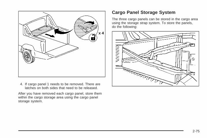
Transcript
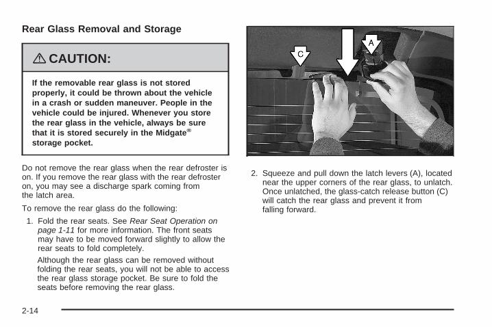
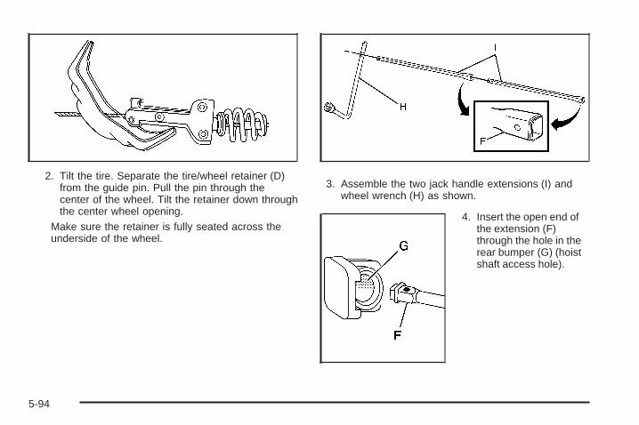
Seats and Restraint Systems ........................... 1-1Front Seats ............................................... 1-2Rear Seats .............................................. 1-11Safety Belts ............................................. 1-13Child Restraints ....................................... 1-34Airbag System ......................................... 1-56Restraint System Check ............................ 1-71
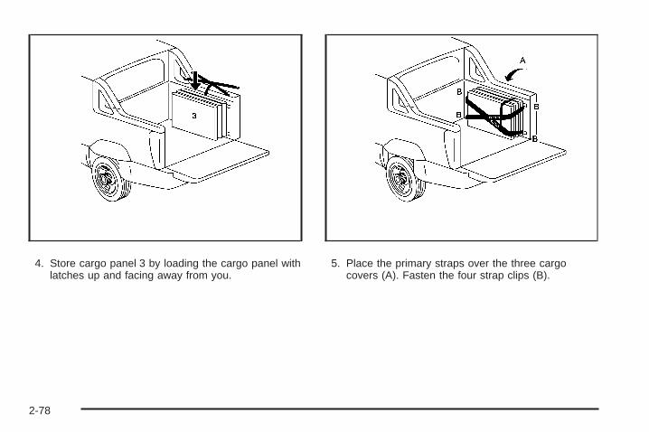
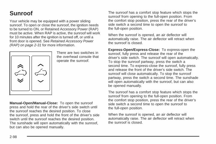
Features and Controls ..................................... 2-1Keys ........................................................ 2-3Doors and Locks ...................................... 2-10Windows ................................................. 2-23Theft-Deterrent Systems ............................ 2-26Starting and Operating Your Vehicle ........... 2-29Mirrors .................................................... 2-51Object Detection Systems .......................... 2-59OnStar® System ...................................... 2-61Universal Home Remote System ................ 2-64Storage Areas ......................................... 2-71Sunroof .................................................. 2-98
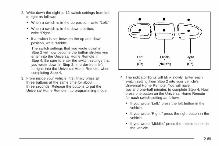
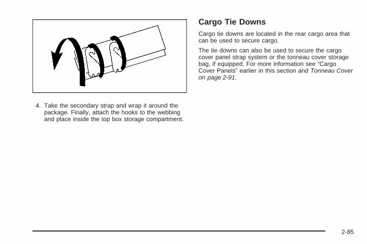
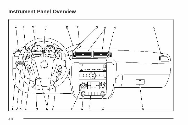
Instrument Panel ............................................. 3-1Instrument Panel Overview .......................... 3-4Climate Controls ...................................... 3-20Warning Lights, Gages, and Indicators ........ 3-30Driver Information Center (DIC) .................. 3-47Audio System(s) ....................................... 3-71
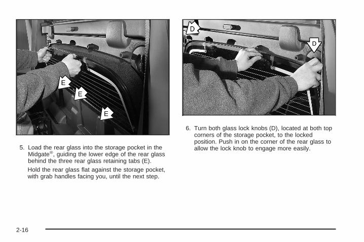
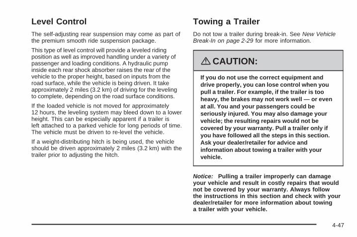
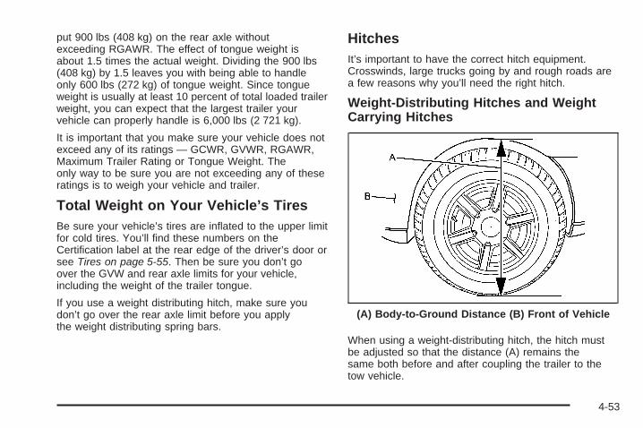
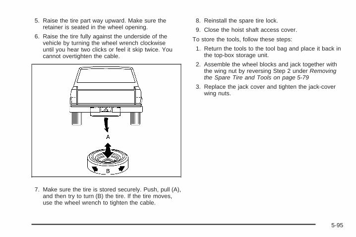
Driving Your Vehicle ....................................... 4-1Your Driving, the Road, and Your Vehicle ..... 4-2Towing ................................................... 4-42
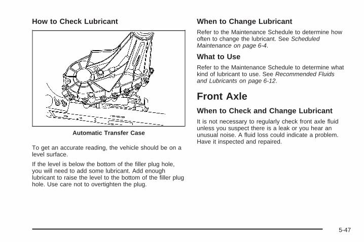
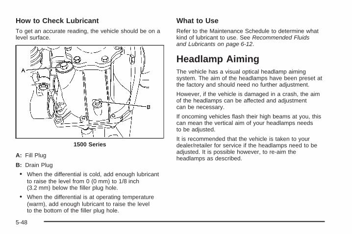
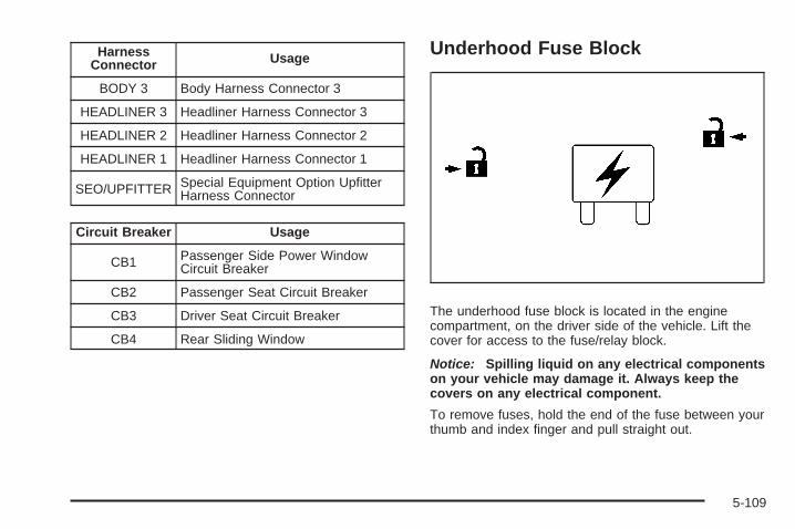
Service and Appearance Care .......................... 5-1Service ..................................................... 5-3Fuel ......................................................... 5-5Checking Things Under the Hood ............... 5-12Rear Axle ............................................... 5-45Four-Wheel Drive ..................................... 5-46Front Axle ............................................... 5-47Headlamp Aiming ..................................... 5-48Bulb Replacement .................................... 5-51Windshield Wiper Blade Replacement ......... 5-54Tires ...................................................... 5-55Appearance Care ..................................... 5-96Vehicle Identification ............................... 5-105Electrical System .................................... 5-105Capacities and Specifications ................... 5-113
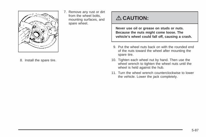
Customer Assistance Information .................... 7-1Customer Assistance and Information ........... 7-2Reporting Safety Defects ........................... 7-14Vehicle Data Recording and Privacy ........... 7-16
Index ................................................................ 1
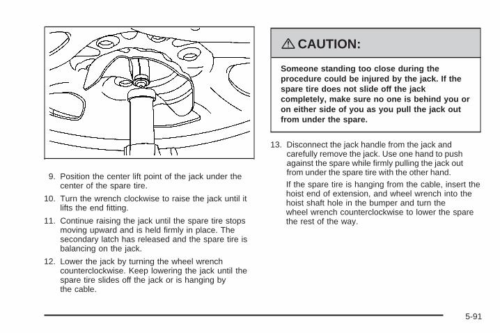
2008 Chevrolet Avalanche Owner Manual M
GENERAL MOTORS, GM, the GM Emblem,CHEVROLET, the CHEVROLET Emblem, and thenames AVALANCHE and Z71 are registered trademarksof General Motors Corporation.
This manual includes the latest information at the time itwas printed. We reserve the right to make changesafter that time without further notice. For vehicles firstsold in Canada, substitute the name “General Motors ofCanada Limited” for Chevrolet Motor Division wheneverit appears in this manual.
This manual describes features that may be available inthis model, but your vehicle may not have all of them.For example, more than one entertainment system maybe offered or your vehicle may have been orderedwithout a front passenger or rear seats.
Keep this manual in the vehicle for quick reference.
Canadian OwnersA French language copy of this manual can be obtainedfrom your dealer/retailer or from:
Helm, IncorporatedP.O. Box 07130Detroit, MI 48207
1-800-551-4123www.helminc.com
Propriétaires CanadiensOn peut obtenir un exemplaire de ce guide en françaisauprès de concessionnaire ou à l’adresse suivante:
Using this ManualMany people read the owner manual from beginning toend when they first receive their new vehicle to learnabout the vehicle’s features and controls. Picturesand words work together to explain things.
IndexA good place to quickly locate information about thevehicle is the Index in the back of the manual. It is analphabetical list of what is in the manual and thepage number where it can be found.
Safety Warnings and SymbolsThere are a number of safety cautions in this book. Abox with the word CAUTION is used to tell about thingsthat could hurt you or others if you were to ignore thewarning.
{CAUTION:
These mean there is something that could hurtyou or other people.
We tell you what the hazard is and what to do to helpavoid or reduce the hazard. Please read these cautions.If you do not, you or others could be hurt.
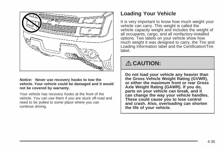
A circle with a slashthrough it is a safetysymbol which means “DoNot,” “Do Not do this”or “Do Not let this happen.”
iii
Vehicle Damage WarningsYou will also find notices in this manual.
Notice: These mean there is something that coulddamage your vehicle.
A notice tells about something that can damage thevehicle. Many times, this damage would not be coveredby your vehicle’s warranty, and it could be costly.The notice tells what to do to help avoid the damage.
When you read other manuals, you might seeCAUTION and NOTICE warnings in different colors or indifferent words.
There are also warning labels on the vehicle which usethe same words, CAUTION or NOTICE.
Vehicle SymbolsThe vehicle has components and labels that usesymbols instead of text. Symbols are shown along withthe text describing the operation or informationrelating to a specific component, control, message,gage, or indicator.
Safety Belts ...................................................1-13Safety Belts: They Are for Everyone ................1-13How to Wear Safety Belts Properly .................1-18Lap-Shoulder Belt .........................................1-26Safety Belt Use During Pregnancy ..................1-32Lap Belt ......................................................1-32Safety Belt Extender .....................................1-33
Child Restraints .............................................1-34Older Children ..............................................1-34Infants and Young Children ............................1-36Child Restraint Systems .................................1-40
Where to Put the Restraint .............................1-42Lower Anchors and Tethers for Children
(LATCH) ..................................................1-43Securing a Child Restraint in a Rear Seat
Position ...................................................1-50Securing a Child Restraint in the Center Front
Seat Position ............................................1-52Securing a Child Restraint in the Right Front
Seat Position ............................................1-53Airbag System ...............................................1-56
Where Are the Airbags? ................................1-59When Should an Airbag Inflate? .....................1-61What Makes an Airbag Inflate? .......................1-62How Does an Airbag Restrain? .......................1-62What Will You See After an Airbag Inflates? .....1-63Passenger Sensing System ............................1-64Servicing Your Airbag-Equipped Vehicle ...........1-69Adding Equipment to Your Airbag-Equipped
Vehicle ....................................................1-70Restraint System Check ..................................1-71
Checking the Restraint Systems ......................1-71Replacing Restraint System Parts After
a Crash ...................................................1-72
Section 1 Seats and Restraint Systems
1-1
Front Seats
Manual Seats
{CAUTION:
You can lose control of the vehicle if you try toadjust a manual driver’s seat while the vehicleis moving. The sudden movement could startleand confuse you, or make you push a pedalwhen you do not want to. Adjust the driver’sseat only when the vehicle is not moving.
To move a manual seat forward or rearward:
1. Lift the bar to unlockthe seat.
2. Slide the seat to thedesired position andrelease the bar.
Try to move the seat with your body to be sure the seatis locked in place.
1-2
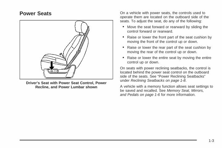
Power Seats On a vehicle with power seats, the controls used tooperate them are located on the outboard side of theseats. To adjust the seat, do any of the following:
• Move the seat forward or rearward by sliding thecontrol forward or rearward.
• Raise or lower the front part of the seat cushion bymoving the front of the control up or down.
• Raise or lower the rear part of the seat cushion bymoving the rear of the control up or down.
• Raise or lower the entire seat by moving the entirecontrol up or down.
On seats with power reclining seatbacks, the control islocated behind the power seat control on the outboardside of the seats. See “Power Reclining Seatbacks”under Reclining Seatbacks on page 1-8.
A vehicle with a memory function allows seat settings tobe saved and recalled. See Memory Seat, Mirrors,and Pedals on page 1-6 for more information.
Driver’s Seat with Power Seat Control, PowerRecline, and Power Lumbar shown
1-3
Manual Lumbar
On vehicles with this feature, turn the knob forward orrearward to increase or decrease lumbar support.
Power Lumbar
If the seats have power lumbar, the controls used tooperate this feature are located on the outboard side ofthe seats.• To increase lumbar support, press and hold the
front of the control.• To decrease lumbar support, press and hold the
rear of the control.• To raise the height of the lumbar support, press
and hold the top of the control.• To lower the height of the lumbar support, press
and hold the bottom of the control.
1-4
Release the control when the lower seatback reachesthe desired level of lumbar support.
Your vehicle may have a memory function which allowsseat settings to be saved and recalled. See MemorySeat, Mirrors, and Pedals on page 1-6 for moreinformation.
Keep in mind that as your seating position changes,as it may during long trips, so should the position ofyour lumbar support. Adjust the seat as needed.
Heated SeatsOn vehicles with heated front seats, the controls arelocated on the driver’s and passenger’s doors.
I (Heated Seatback): Press to turn on the heatedseatback.
J (Heated Seat and Seatback): Press to turn on theheated seat and seatback.
The light on the button will come on to indicate that thefeature is working. Press the button to cycle throughthe temperature settings of high, medium, and low andto turn the heat to the seat off. Indicator lights willshow the level of heat selected: three for high, two formedium, and one for low.
The heated seats will be canceled ten seconds after theignition is turned off. To use the heated seat featureafter restarting your vehicle, press the heated seator seatback button again.
1-5
Memory Seat, Mirrors, and PedalsYour vehicle may have the memory package.
The controls for thisfeature are located on thedriver’s door panel, andare used to programand recall memory settingsfor the driver’s seat,outside mirrors, and theadjustable throttle andbrake pedal.
To save your positions in memory, do the following:
1. Adjust the driver’s seat, including the seatbackrecliner and lumbar, both outside mirrors, andthe throttle and brake pedals to a comfortableposition.See Outside Power Mirrors on page 2-55 andAdjustable Throttle and Brake Pedal on page 2-33for more information.Not all mirrors will have the ability to save andrecall their positions.Not all adjustable throttles and brake pedals willhave the ability to save and recall their positions.
2. Press and hold button 1 until two beeps are heardindicating that the position has been stored.
A second seating, mirror, and throttle and brake pedalposition can be programmed by repeating the abovesteps and pressing button 2.
1-6
To recall the memory positions, the vehicle must be inPARK (P). Press and release either button 1 or button 2corresponding to the desired driving position. Theseat, outside mirrors, and adjustable throttle and brakepedals will move to the position previously stored.You will hear a single beep.
If you use the remote keyless entry transmitter to enteryour vehicle and the remote recall memory featureis on, automatic seat, adjustable mirror, and adjustablepedal movements will occur. See “MEMORY SEATRECALL” under DIC Vehicle Customization (With DICButtons) on page 3-63 for more information.
To stop recall movement of the memory function at anytime, press one of the power seat controls, memorybuttons, power mirror buttons, or adjustable pedalswitch.
If something has blocked the driver’s seat and/or theadjustable pedals while recalling a memory position, thedriver’s seat and/or the adjustable pedals recall maystop working. If this happens, remove the obstructionand press the appropriate control for the area that is notresponding for two seconds. Try recalling the memoryposition again by pressing the appropriate memorybutton. If the memory position is still not recalling, seeyour dealer for service.
Easy Exit SeatThe control for this feature is located on the driver’sdoor panel between buttons 1 and 2.
With the vehicle in PARK (P), the driver’s seat exitposition can be recalled by pressing the exit button.You will hear a single beep, and the driver’s seatwill move back.
If the easy exit seat feature is programmed in the DriverInformation Center (DIC), automatic seat movementwill occur when the key is removed from the ignition.See “EASY EXIT SEAT” under DIC VehicleCustomization (With DIC Buttons) on page 3-63 formore information.
The memory seat and easy exit features can also beprogrammed using the DIC.
For programming information, see DIC VehicleCustomization (With DIC Buttons) on page 3-63.
1-7
Reclining Seatbacks
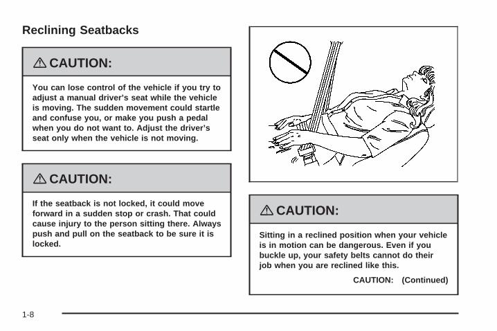
{CAUTION:
You can lose control of the vehicle if you try toadjust a manual driver’s seat while the vehicleis moving. The sudden movement could startleand confuse you, or make you push a pedalwhen you do not want to. Adjust the driver’sseat only when the vehicle is not moving.
{CAUTION:
If the seatback is not locked, it could moveforward in a sudden stop or crash. That couldcause injury to the person sitting there. Alwayspush and pull on the seatback to be sure it islocked.
{CAUTION:
Sitting in a reclined position when your vehicleis in motion can be dangerous. Even if youbuckle up, your safety belts cannot do theirjob when you are reclined like this.
CAUTION: (Continued)
1-8
CAUTION: (Continued)
The shoulder belt cannot do its job. In a crash,you could go into it, receiving neck or otherinjuries.
The lap belt cannot do its job either. In a crashthe belt could go up over your abdomen.The belt forces would be there, not at yourpelvic bones. This could cause seriousinternal injuries.
For proper protection when the vehicle is inmotion, have the seatback upright. Then sitwell back in the seat and wear your safety beltproperly.
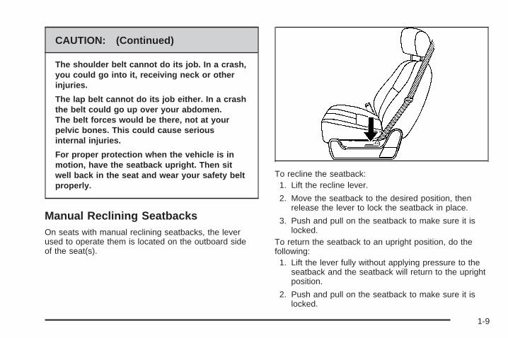
Manual Reclining SeatbacksOn seats with manual reclining seatbacks, the leverused to operate them is located on the outboard sideof the seat(s).
To recline the seatback:1. Lift the recline lever.
2. Move the seatback to the desired position, thenrelease the lever to lock the seatback in place.
3. Push and pull on the seatback to make sure it islocked.
To return the seatback to an upright position, do thefollowing:1. Lift the lever fully without applying pressure to the
seatback and the seatback will return to the uprightposition.
2. Push and pull on the seatback to make sure it islocked.
1-9
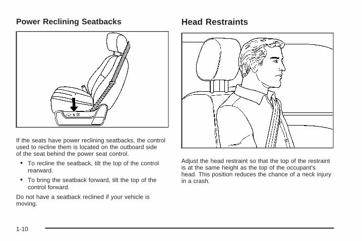
Power Reclining Seatbacks
If the seats have power reclining seatbacks, the controlused to recline them is located on the outboard sideof the seat behind the power seat control.
• To recline the seatback, tilt the top of the controlrearward.
• To bring the seatback forward, tilt the top of thecontrol forward.
Do not have a seatback reclined if your vehicle ismoving.
Head Restraints
Adjust the head restraint so that the top of the restraintis at the same height as the top of the occupant’shead. This position reduces the chance of a neck injuryin a crash.
1-10
Pull the head restraint up toraise it. To lower the headrestraint, press the releasebutton, located on thetop of the seatback,while you push the headrestraint down.
Center SeatYour vehicle may have a front center seat. The seatbackdoubles as an armrest and cupholder/storage area forthe driver and passenger when the center seat isnot used. Do not use it as a seating position when theseatback is folded down.
Rear Seats
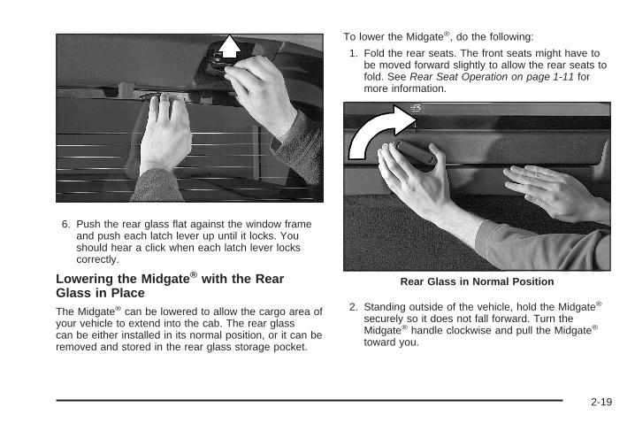
Rear Seat OperationThe rear seat is a 60/40 split bench seat that can befolded to give you more cargo space and access to thefolding midgate. See Midgate® on page 2-12 formore information on operation of the folding midgate.
To fold either side of the seat do the following:1. Push the rear seat head restraints all the
way down.
2. Pull the seat looplocated where theseatback and seatcushion meet. The seatcushion will release andallow you to tilt it towardthe front of the vehicle.
Notice: Folding a rear seat with the safety beltsstill fastened may cause damage to the seat or thesafety belts. Always unbuckle the safety beltsand return them to their normal stowed positionbefore folding a rear seat.
1-11
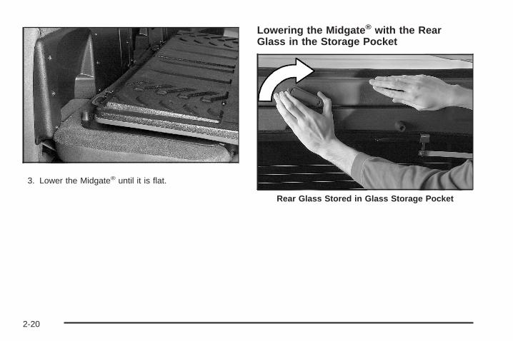
3. Fold the seatback forward until it is flat. You mayhave to move the front seats forward slightlyto do this.
4. Repeat the procedure for the other side.
To return the seats to the normal position, push theseatback up and fold the seat cushion down.
{CAUTION:
A safety belt that is improperly routed, notproperly attached, or twisted will not providethe protection needed in a crash. The personwearing the belt could be seriously injured.After raising the rear seatback, always checkto be sure that the safety belts are properlyrouted and attached, and are not twisted.
{CAUTION:
If the seatback is not locked, it could moveforward in a sudden stop or crash. That couldcause injury to the person sitting there. Alwaysbe sure to press the rear of the seat cushiondown. This action locks the seatback in place.
Push and pull on the seatback to make sure it is locked.Raise the head restraint.
1-12
Safety Belts
Safety Belts: They Are for EveryoneThis part of the manual tells you how to use safetybelts properly. It also tells you some things you shouldnot do with safety belts.
{CAUTION:
Do not let anyone ride where he or she cannotwear a safety belt properly. If you are in acrash and you are not wearing a safety belt,your injuries can be much worse. You can hitthings inside the vehicle harder or be ejectedfrom it and be seriously injured or killed. In thesame crash, you might not be, if you arebuckled up. Always fasten your safety belt,and check that your passenger(s) arerestrained properly too.
{CAUTION:
People riding on the tailgate (if equipped) caneasily lose their balance and fall even whenthe vehicle is operated at low speeds. Fallingfrom a moving vehicle may result in seriousinjuries or death.
{CAUTION:
It is extremely dangerous to ride in a cargoarea, inside or outside of a vehicle. In acollision, people riding in these areas are morelikely to be seriously injured or killed. Do notallow people to ride in any area of your vehiclethat is not equipped with seats and safetybelts. Be sure everyone in your vehicle is in aseat and using a safety belt properly.
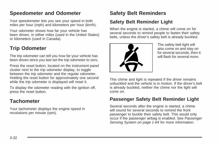
Your vehicle has indicators as a reminder to buckle yoursafety belts. See Safety Belt Reminders on page 3-32.
1-13
In most states and in all Canadian provinces, the lawrequires wearing safety belts. Here is why:
You never know if you will be in a crash. If you do havea crash, you do not know if it will be a serious one.
A few crashes are mild, and some crashes can be soserious that even buckled up, a person would notsurvive. But most crashes are in between. In many ofthem, people who buckle up can survive and sometimeswalk away. Without belts they could have been badlyhurt or killed.
After more than 40 years of safety belts in vehicles, thefacts are clear. In most crashes buckling up doesmatter... a lot!
Why Safety Belts WorkWhen you ride in or on anything, you go as fastas it goes.
Take the simplest vehicle. Suppose it is just a seaton wheels.
1-14
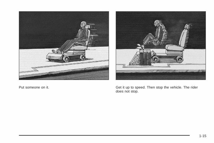
Put someone on it. Get it up to speed. Then stop the vehicle. The riderdoes not stop.
1-15
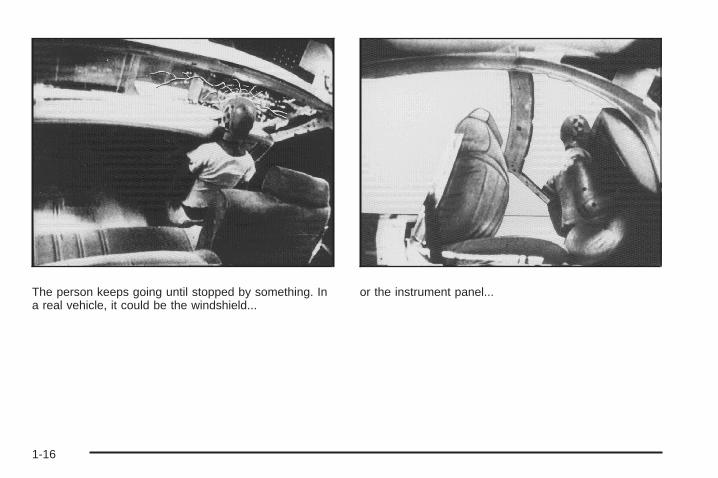
The person keeps going until stopped by something. Ina real vehicle, it could be the windshield...
or the instrument panel...
1-16
or the safety belts!
With safety belts, you slow down as the vehicle does.You get more time to stop. You stop over more distance,and your strongest bones take the forces. That is whysafety belts make such good sense.
Questions and Answers About SafetyBelts
Q: Will I be trapped in the vehicle after a crash if Iam wearing a safety belt?
A: You could be — whether you are wearing a safetybelt or not. But your chance of being consciousduring and after an accident, so you can unbuckleand get out, is much greater if you are belted.And you can unbuckle a safety belt, even if you areupside down.
Q: If my vehicle has airbags, why should I have towear safety belts?
A: Airbags are supplemental systems only; so theywork with safety belts — not instead of them.Whether or not an airbag is provided, all occupantsstill have to buckle up to get the most protection.That is true not only in frontal collisions, butespecially in side and other collisions.
1-17
Q: If I am a good driver, and I never drive far fromhome, why should I wear safety belts?
A: You may be an excellent driver, but if you are in acrash — even one that is not your fault — you andyour passenger(s) can be hurt. Being a gooddriver does not protect you from things beyond yourcontrol, such as bad drivers.
Most accidents occur within 25 miles (40 km) ofhome. And the greatest number of serious injuriesand deaths occur at speeds of less than 40 mph(65 km/h).
Safety belts are for everyone.
How to Wear Safety Belts ProperlyThis section is only for people of adult size.
Be aware that there are special things to know aboutsafety belts and children. And there are differentrules for smaller children and babies. If a child will beriding in your vehicle, see Older Children on page 1-34or Infants and Young Children on page 1-36. Followthose rules for everyone’s protection.
It is very important for all occupants to buckle up.Statistics show that unbelted people are hurt more oftenin crashes than those who are wearing safety belts.
Occupants who are not buckled up can be thrown out ofthe vehicle in a crash. And they can strike others inthe vehicle who are wearing safety belts.
First, before you or your passenger(s) wear a safetybelt, there is important information you should know.
1-18
Sit up straight and always keep your feet on the floor infront of you. The lap part of the belt should be wornlow and snug on the hips, just touching the thighs. In acrash, this applies force to the strong pelvic bonesand you would be less likely to slide under the lap belt.If you slid under it, the belt would apply force onyour abdomen. This could cause serious or even fatalinjuries. The shoulder belt should go over the shoulderand across the chest. These parts of the body arebest able to take belt restraining forces.
The shoulder belt locks if there is a sudden stop orcrash.
1-19
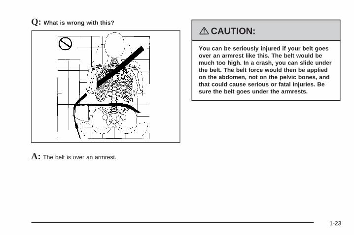
Q: What is wrong with this?
A: The shoulder belt is too loose. It will not give asmuch protection this way.
{CAUTION:
You can be seriously hurt if your shoulder beltis too loose. In a crash, you would moveforward too much, which could increase injury.The shoulder belt should fit snugly againstyour body.
1-20
Q: What is wrong with this?
A: The lap belt is too loose. It will not give nearly asmuch protection this way.
{CAUTION:
You can be seriously hurt if your lap belt is tooloose. In a crash, you could slide under the lapbelt and apply force on your abdomen. Thiscould cause serious or even fatal injuries. Thelap belt should be worn low and snug on thehips, just touching the thighs.
1-21
Q: What is wrong with this?
A: The belt is buckled in the wrong place.
{CAUTION:
You can be seriously injured if your belt isbuckled in the wrong place like this. In a crash,the belt would go up over your abdomen. Thebelt forces would be there, not on the pelvicbones. This could cause serious internalinjuries. Always buckle your belt into thebuckle nearest you.
1-22
Q: What is wrong with this?
A: The belt is over an armrest.
{CAUTION:
You can be seriously injured if your belt goesover an armrest like this. The belt would bemuch too high. In a crash, you can slide underthe belt. The belt force would then be appliedon the abdomen, not on the pelvic bones, andthat could cause serious or fatal injuries. Besure the belt goes under the armrests.
1-23
Q: What is wrong with this?
A: The shoulder belt is worn under the arm. It shouldbe worn over the shoulder at all times.
{CAUTION:
You can be seriously injured if you wear theshoulder belt under your arm. In a crash, yourbody would move too far forward, which wouldincrease the chance of head and neck injury.Also, the belt would apply too much force tothe ribs, which are not as strong as shoulderbones. You could also severely injure internalorgans like your liver or spleen. The shoulderbelt should go over the shoulder and acrossthe chest.
1-24
Q: What is wrong with this?
A: The belt is behind the body.
{CAUTION:
You can be seriously injured by not wearingthe lap-shoulder belt properly. In a crash, youwould not be restrained by the shoulder belt.Your body could move too far forwardincreasing the chance of head and neck injury.You might also slide under the lap belt. Thebelt force would then be applied right on theabdomen. That could cause serious or fatalinjuries. The shoulder belt should go over theshoulder and across the chest.
1-25
Q: What is wrong with this?
A: The belt is twisted across the body.
{CAUTION:
You can be seriously injured by a twisted belt.In a crash, you would not have the full width ofthe belt to spread impact forces. If a belt istwisted, make it straight so it can workproperly, or ask your dealer/retailer to fix it.
Lap-Shoulder BeltAll seating positions in your vehicle have a lap-shoulderbelt except for the center front passenger position (ifequipped), which has a lap belt. See Lap Belt onpage 1-32 for more information.
Here is how to wear a lap-shoulder belt properly.
1. Adjust the seat, if the seat is adjustable, so you cansit up straight. To see how, see “Seats” in the Index.
2. Pick up the latch plate and pull the belt across you.Do not let it get twisted.The lap-shoulder belt may lock if you pull the beltacross you very quickly. If this happens, let the beltgo back slightly to unlock it. Then pull the beltacross you more slowly.
1-26
If you ever pull the shoulder portion of a passengerbelt out all the way, you may engage the childrestraint locking feature. If this happens, just let thebelt go back all the way and start again.Engaging the child restraint locking feature mayaffect the passenger sensing system. SeePassenger Sensing System on page 1-64.
3. Push the latch plate into the buckle until it clicks.If you find that the latch plate will not go fully intothe buckle, see if you are using the correct buckle.Pull up on the latch plate to make sure it issecure. If the belt is not long enough, see SafetyBelt Extender on page 1-33.
Make sure the release button on the buckle ispositioned so you would be able to unbuckle thesafety belt quickly if necessary.
4. If equipped with a shoulder belt height adjuster,move it to the height that is right for you. Impropershoulder belt height adjustment could reducethe effectiveness of the safety belt in a crash.See “Shoulder Belt Height Adjustment” later in thissection.
5. To make the lap part tight, pull up on theshoulder belt.
1-27
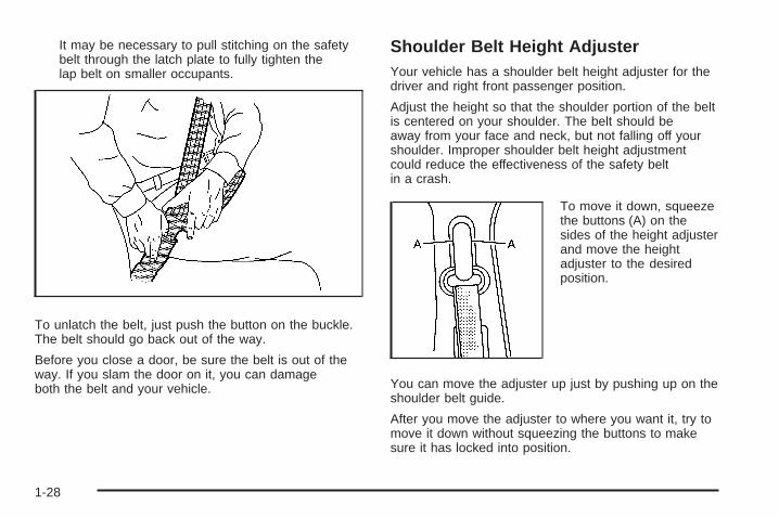
It may be necessary to pull stitching on the safetybelt through the latch plate to fully tighten thelap belt on smaller occupants.
To unlatch the belt, just push the button on the buckle.The belt should go back out of the way.
Before you close a door, be sure the belt is out of theway. If you slam the door on it, you can damageboth the belt and your vehicle.
Shoulder Belt Height AdjusterYour vehicle has a shoulder belt height adjuster for thedriver and right front passenger position.
Adjust the height so that the shoulder portion of the beltis centered on your shoulder. The belt should beaway from your face and neck, but not falling off yourshoulder. Improper shoulder belt height adjustmentcould reduce the effectiveness of the safety beltin a crash.
To move it down, squeezethe buttons (A) on thesides of the height adjusterand move the heightadjuster to the desiredposition.
You can move the adjuster up just by pushing up on theshoulder belt guide.
After you move the adjuster to where you want it, try tomove it down without squeezing the buttons to makesure it has locked into position.
1-28
Safety Belt PretensionersYour vehicle has safety belt pretensioners for frontoutboard occupants. Although you cannot see them,they are part of the safety belt assembly. They can helptighten the safety belts during the early stages of amoderate to severe frontal, near frontal, or rear crash ifthe threshold conditions for pretensioner activationare met. And, if your vehicle has side impact airbags,safety belt pretensioners can help tighten the safetybelts in a side crash or a rollover event.
Pretensioners work only once. If they activate in acrash, you will need to get new ones, and probably othernew parts for your safety belt system. See ReplacingRestraint System Parts After a Crash on page 1-72.
Rear Safety Belt Comfort GuidesRear shoulder belt comfort guides may provide addedsafety belt comfort for older children who have outgrownbooster seats and for some adults. When installed ona shoulder belt, the comfort guide positions the beltaway from the neck and head.
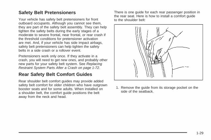
There is one guide for each rear passenger position inthe rear seat. Here is how to install a comfort guideto the shoulder belt:
1. Remove the guide from its storage pocket on theside of the seatback.
1-29
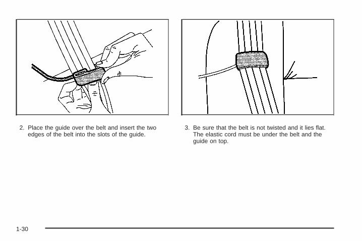
2. Place the guide over the belt and insert the twoedges of the belt into the slots of the guide.
3. Be sure that the belt is not twisted and it lies flat.The elastic cord must be under the belt and theguide on top.
1-30
{CAUTION:
A safety belt that is not properly worn may notprovide the protection needed in a crash. Theperson wearing the belt could be seriouslyinjured. The shoulder belt should go over theshoulder and across the chest. These parts ofthe body are best able to take belt restrainingforces.
4. Buckle, position, and release the safety belt asdescribed previously in this section. Make surethat the shoulder belt crosses the shoulder.
To remove and store the comfort guide, squeeze thebelt edges together so that you can take them out of theguide. Slide the guide into its storage pocket on theside of the seatback.
1-31
Safety Belt Use During PregnancySafety belts work for everyone, including pregnantwomen. Like all occupants, they are more likely to beseriously injured if they do not wear safety belts.
A pregnant woman should wear a lap-shoulder belt, andthe lap portion should be worn as low as possible,below the rounding, throughout the pregnancy.
The best way to protect the fetus is to protect themother. When a safety belt is worn properly, it is morelikely that the fetus will not be hurt in a crash. Forpregnant women, as for anyone, the key to makingsafety belts effective is wearing them properly.
Lap BeltThis part is only for the lap belt. To learn how to wear alap-shoulder belt, see Lap-Shoulder Belt on page 1-26.
You vehicle may have a center seating position.When you sit in the center front seating position, youhave a lap safety belt, which has no retractor.
To make the belt longer, tilt the latch plate and pull italong the belt.
Buckle, position and release it the same way as the lappart of a lap-shoulder belt.
1-32
To make the belt shorter, pull its free end as shownuntil the belt is snug.
If the belt is not long enough, see Safety Belt Extenderon page 1-33.
Make sure the release button on the buckle is positionedso you would be able to unbuckle the safety beltquickly if necessary.
If you find that the latch plate will not go fully into thebuckle, see if you are using the correct buckle. Be surethat the latch plate clicks when inserted into thebuckle.
Safety Belt ExtenderIf the vehicle’s safety belt will fasten around you, youshould use it.
But if a safety belt is not long enough, yourdealer/retailer will order you an extender. When you goin to order it, take the heaviest coat you will wear,so the extender will be long enough for you. To helpavoid personal injury, do not let someone else useit, and use it only for the seat it is made to fit. Theextender has been designed for adults. Never use it forsecuring child seats. To wear it, attach it to theregular safety belt. For more information, see theinstruction sheet that comes with the extender.
1-33
Child Restraints
Older Children
Older children who have outgrown booster seats shouldwear the vehicle’s safety belts.
The manufacturer’s instructions that come with thebooster seat, state the weight and height limitations forthat booster. Use a booster seat with a lap-shoulderbelt until the child passes the below fit test:
• Sit all the way back on the seat. Do the knees bendat the seat edge? If yes, continue. If no, return tothe booster seat.
• Buckle the lap-shoulder belt. Does the shoulder beltrest on the shoulder? If yes, continue. If no, tryusing the rear safety belt comfort guide. See “RearSafety Belt Comfort Guides” under Lap-ShoulderBelt on page 1-26 for more information. If theshoulder belt still does not rest on the shoulder,then return to the booster seat.
• Does the lap belt fit low and snug on the hips,touching the thighs? If yes, continue. If no, return tothe booster seat.
• Can proper safety belt fit be maintained forlength of trip? If yes, continue. If no, return to thebooster seat.
If you have the choice, a child should sit in a positionwith a lap-shoulder belt and get the additional restraint ashoulder belt can provide.
1-34
Q: What is the proper way to wear safety belts?
A: An older child should wear a lap-shoulder belt andget the additional restraint a shoulder belt canprovide. The shoulder belt should not cross the faceor neck. The lap belt should fit snugly below thehips, just touching the top of the thighs. This appliesbelt force to the child’s pelvic bones in a crash. Itshould never be worn over the abdomen, whichcould cause severe or even fatal internal injuries ina crash.
Also see “Rear Safety Belt Comfort Guides” underLap-Shoulder Belt on page 1-26.
According to accident statistics, children and infants aresafer when properly restrained in the rear seatingpositions than in the front seating positions.
In a crash, children who are not buckled up can strikeother people who are buckled up, or can be thrownout of the vehicle. Older children need to use safetybelts properly.
{CAUTION:
Never do this.
Here two children are wearing the same belt.The belt cannot properly spread the impactforces. In a crash, the two children can becrushed together and seriously injured. A beltmust be used by only one person at a time.
1-35
{CAUTION:
Never do this.
Here a child is sitting in a seat that has alap-shoulder belt, but the shoulder part isbehind the child. In a crash, the child wouldnot be restrained by the shoulder belt. Thechild might slide under the lap belt. The beltforce would then be applied right on theabdomen. That could cause serious or fatalinjuries. The child could also move too farforward increasing the chance of head andneck injury. The shoulder belt should go overthe shoulder and across the chest. Infants and Young Children
Everyone in a vehicle needs protection! This includesinfants and all other children. Neither the distancetraveled nor the age and size of the traveler changesthe need, for everyone, to use safety restraints. In fact,the law in every state in the United States and inevery Canadian province says children up to some agemust be restrained while in a vehicle.
1-36
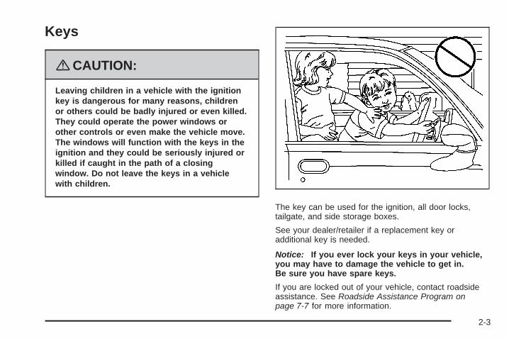
{CAUTION:
Children can be seriously injured or strangled ifa shoulder belt is wrapped around their neckand the safety belt continues to tighten. Neverleave children unattended in a vehicle and neverallow children to play with the safety belts.
Every time infants and young children ride in vehicles,they should have the protection provided by appropriaterestraints. Children who are not restrained properly canstrike other people, or can be thrown out of the vehicle. Inaddition, young children should not use the vehicle’sadult safety belts alone; they need to use a child restraint.
{CAUTION:
People should never hold an infant in theirarms while riding in a vehicle. An infant doesnot weigh much — until a crash. During acrash an infant will become so heavy it is not
CAUTION: (Continued)
CAUTION: (Continued)
possible to hold it. For example, in a crash atonly 25 mph (40 km/h), a 12 lb (5.5 kg) infantwill suddenly become a 240 lb (110 kg) forceon a person’s arms. An infant should besecured in an appropriate restraint.
1-37
{CAUTION:
Children who are up against, or very close to,any airbag when it inflates can be seriouslyinjured or killed. Airbags plus lap-shoulderbelts offer protection for adults and olderchildren, but not for young children andinfants. Neither the vehicle’s safety belt systemnor its airbag system is designed for them.Young children and infants need the protectionthat a child restraint system can provide.
Q: What are the different types of add-on childrestraints?
A: Add-on child restraints, which are purchased by thevehicle’s owner, are available in four basic types.Selection of a particular restraint should takeinto consideration not only the child’s weight, height,and age but also whether or not the restraint willbe compatible with the motor vehicle in which it willbe used.
1-38
For most basic types of child restraints, there aremany different models available. When purchasing achild restraint, be sure it is designed to be usedin a motor vehicle. If it is, the restraint will have alabel saying that it meets federal motor vehiclesafety standards.
The restraint manufacturer’s instructions that comewith the restraint state the weight and heightlimitations for a particular child restraint. In addition,there are many kinds of restraints available forchildren with special needs.
{CAUTION:
Newborn infants need complete support,including support for the head and neck. Thisis necessary because a newborn infant’s neckis weak and its head weighs so muchcompared with the rest of its body. In a crash,an infant in a rear-facing seat settles into therestraint, so the crash forces can bedistributed across the strongest part of aninfant’s body, the back and shoulders. Infantsshould always be secured in appropriate infantrestraints.
{CAUTION:
The body structure of a young child is quiteunlike that of an adult or older child, for whomthe safety belts are designed. A young child’ship bones are still so small that the vehicle’sregular safety belt may not remain low on thehip bones, as it should. Instead, it may settleup around the child’s abdomen. In a crash, thebelt would apply force on a body area that isunprotected by any bony structure. This alonecould cause serious or fatal injuries. Youngchildren should always be secured inappropriate child restraints.
1-39
Child Restraint Systems
A rear-facing infantseat (A) provides restraintwith the seating surfaceagainst the back ofthe infant.
The harness system holds the infant in place and, in acrash, acts to keep the infant positioned in therestraint.
A forward-facing childseat (B) provides restraintfor the child’s bodywith the harness.
A booster seat (C-D) is a child restraint designed toimprove the fit of the vehicle’s safety belt system.A booster seat can also help a child to see out thewindow.
1-40
Securing an Add-On Child Restraint inthe Vehicle
{CAUTION:
A child can be seriously injured or killed in acrash if the child restraint is not properlysecured in the vehicle. Make sure the childrestraint is properly installed in the vehicleusing the vehicle’s safety belt or LATCHsystem, following the instructions that camewith that restraint, and also the instructions inthis manual.
To help reduce the chance of injury, the child restraintmust be secured in the vehicle. Child restraint systemsmust be secured in vehicle seats by lap belts or thelap belt portion of a lap-shoulder belt, or by the LATCHsystem. See Lower Anchors and Tethers for Children(LATCH) on page 1-43 for more information. A child canbe endangered in a crash if the child restraint is notproperly secured in the vehicle.
When securing an add-on child restraint, refer to theinstructions that come with the restraint which may be onthe restraint itself or in a booklet, or both, and to thismanual. The child restraint instructions are important, soif they are not available, obtain a replacement copyfrom the manufacturer.
Keep in mind that an unsecured child restraint canmove around in a collision or sudden stop and injurepeople in the vehicle. Be sure to properly secureany child restraint in your vehicle — even when no childis in it.
Securing the Child Within the ChildRestraint
{CAUTION:
A child can be seriously injured or killed in acrash if the child is not properly secured in thechild restraint. Because there are differentsystems, it is important to refer to theinstructions that come with the restraint. Makesure the child is properly secured, followingthe instructions that came with that restraint.
1-41
Where to Put the RestraintAccident statistics show that children are safer if theyare restrained in the rear rather than the front seat.
We recommend that children and child restraintsbe secured in a rear seat, including: an infant or a childriding in a rear-facing child restraint; a child riding ina forward-facing child seat; an older child riding ina booster seat; and children, who are large enough,using safety belts.
A label on your sun visor says, “Never put a rear-facingchild seat in the front.” This is because the risk to therear-facing child is so great, if the airbag deploys.
{CAUTION:
A child in a rear-facing child restraint can beseriously injured or killed if the right frontpassenger’s airbag inflates. This is becausethe back of the rear-facing child restraintwould be very close to the inflating airbag.
CAUTION: (Continued)
CAUTION: (Continued)
Even though the passenger sensing system isdesigned to turn off the right front passenger’sfrontal airbag if the system detects arear-facing child restraint, no system isfail-safe, and no one can guarantee that anairbag will not deploy under some unusualcircumstance, even though it is turned off. Werecommend that rear-facing child restraints besecured in a rear seat, even if the airbag is off.
If you secure a forward-facing child restraint inthe right front seat, always move the frontpassenger seat as far back as it will go. It isbetter to secure the child restraint in a rear seat.
See Passenger Sensing System on page 1-64for additional information.
1-42
{CAUTION:
A child in a child restraint in the center frontseat can be badly injured or killed by thefrontal airbags if they inflate. Never secure achild restraint in the center front seat. It isalways better to secure a child restraint in arear seat.
Do not use child restraints in the center front seatposition.
When securing a child restraint in a rear seatingposition, study the instructions that came with your childrestraint to make sure it is compatible with this vehicle.
Wherever you install a child restraint, be sure tosecure the child restraint properly.
Keep in mind that an unsecured child restraint canmove around in a collision or sudden stop and injurepeople in the vehicle. Be sure to properly secureany child restraint in your vehicle — even when nochild is in it.
Lower Anchors and Tethers forChildren (LATCH)The LATCH system holds a child restraint during drivingor in a crash. This system is designed to makeinstallation of a child restraint easier. The LATCHsystem uses anchors in the vehicle and attachments onthe child restraint that are made for use with theLATCH system.
Make sure that a LATCH-compatible child restraint isproperly installed using the anchors, or use the vehicle’ssafety belts to secure the restraint, following theinstructions that came with that restraint, and also theinstructions in this manual. When installing a childrestraint with a top tether, you must also use either thelower anchors or the safety belts to properly securethe child restraint. A child restraint must never beinstalled using only the top tether and anchor.
In order to use the LATCH system in your vehicle, youneed a child restraint that has LATCH attachments.The child restraint manufacturer will provide youwith instructions on how to use the child restraint and itsattachments. The following explains how to attach achild restraint with these attachments in your vehicle.
Not all vehicle seating positions or child restraints havelower anchors and attachments or top tether anchorsand attachments.
1-43
Lower Anchors
Lower anchors (A) are metal bars built into the vehicle.There are two lower anchors for each LATCH seatingposition that will accommodate a child restraint withlower attachments (B).
Top Tether Anchor
A top tether (A, C) anchors the top of the child restraintto the vehicle. A top tether anchor is built into thevehicle. The top tether attachment (B) on the childrestraint connects to the top tether anchor in the vehiclein order to reduce the forward movement and rotationof the child restraint during driving or in a crash.
Your child restraint may have a single tether (A) or adual tether (C). Either will have a single attachment (B)to secure the top tether to the anchor.
1-44
Some child restraints that have top tethers are designedfor use with or without the top tether being attached.Others require the top tether always to be attached. InCanada, the law requires that forward-facing childrestraints have a top tether, and that the tether beattached. Be sure to read and follow the instructions foryour child restraint.
If the child restraint does not have a top tether, one canbe obtained, in kit form, for many child restraints. Askthe child restraint manufacturer whether or not a kitis available.
Lower Anchor and Top Tether AnchorLocations
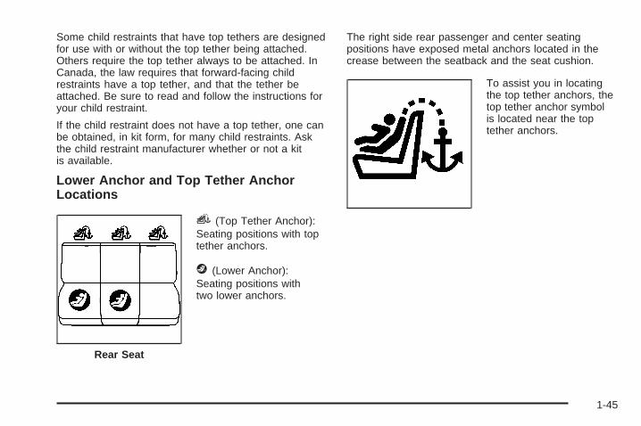
i (Top Tether Anchor):Seating positions with toptether anchors.
The right side rear passenger and center seatingpositions have exposed metal anchors located in thecrease between the seatback and the seat cushion.
To assist you in locatingthe top tether anchors, thetop tether anchor symbolis located near the toptether anchors.
Rear Seat
1-45
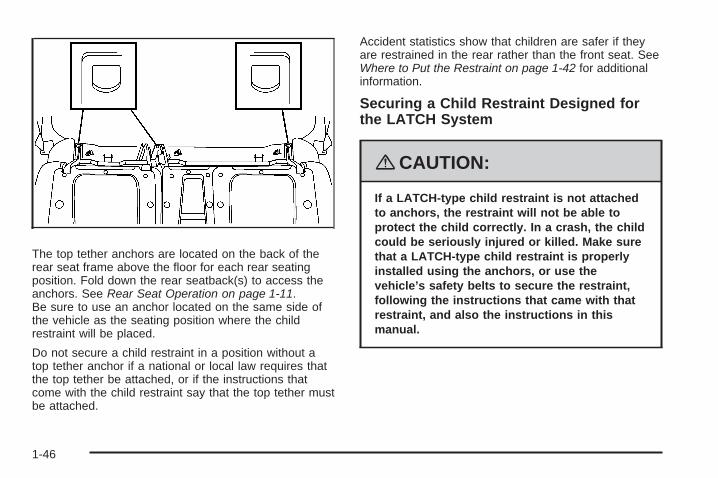
The top tether anchors are located on the back of therear seat frame above the floor for each rear seatingposition. Fold down the rear seatback(s) to access theanchors. See Rear Seat Operation on page 1-11.Be sure to use an anchor located on the same side ofthe vehicle as the seating position where the childrestraint will be placed.
Do not secure a child restraint in a position without atop tether anchor if a national or local law requires thatthe top tether be attached, or if the instructions thatcome with the child restraint say that the top tether mustbe attached.
Accident statistics show that children are safer if theyare restrained in the rear rather than the front seat. SeeWhere to Put the Restraint on page 1-42 for additionalinformation.
Securing a Child Restraint Designed forthe LATCH System
{CAUTION:
If a LATCH-type child restraint is not attachedto anchors, the restraint will not be able toprotect the child correctly. In a crash, the childcould be seriously injured or killed. Make surethat a LATCH-type child restraint is properlyinstalled using the anchors, or use thevehicle’s safety belts to secure the restraint,following the instructions that came with thatrestraint, and also the instructions in thismanual.
1-46
{CAUTION:
Each top tether anchor and lower anchor in thevehicle is designed to hold only one childrestraint. Attaching more than one childrestraint to a single anchor could cause theanchor or attachment to come loose or evenbreak during a crash. A child or others couldbe injured if this happens. To help preventinjury to people and damage to your vehicle,attach only one child restraint per anchor.
{CAUTION:
Children can be seriously injured or strangledif a shoulder belt is wrapped around their neckand the safety belt continues to tighten.Secure any unused safety belts behind thechild restraint so children cannot reach them.
CAUTION: (Continued)
CAUTION: (Continued)
Pull the shoulder belt all the way out of theretractor to set the lock, if your vehicle hasone, after the child restraint has been installed.Be sure to follow the instructions of the childrestraint manufacturer.
Notice: Contact between the child restraint LATCHattachment parts and the vehicle’s safety beltassembly may cause damage to these parts. Makesure when securing unused safety belts behindthe child restraint that there is no contact betweenthe child restraint LATCH attachment parts andthe vehicle’s safety belt assembly.
Folding an empty rear seat with the safety beltssecured may cause damage to the safety belt or theseat. When removing the child restraint, alwaysremember to return the safety belts to their normal,stowed position before folding the rear seat.
1-47
1. If the child restraint manufacturer recommends thatthe top tether be attached, attach the top tether tothe top tether anchor, if there is one. Refer tothe child restraint instructions and the followingsteps:
1.1. To access the top tether anchors, raise theseat cushion by pulling up on the strap loopat the rear of the seat cushion and foldthe seat cushion forward. Then foldthe seatback forward until it is flat. See RearSeat Operation on page 1-11 for additionalinformation.
1.2. Place the child restraint in the vehicle, nearthe seating position that you are using.
1.3. Route the top tether according to your childrestraint instructions and the followinginstructions:
If the position you areusing does not have aheadrest or head restraintand you are using asingle tether, route thetether over the seatback.
If the position you areusing does not have aheadrest or head restraintand you are using adual tether, route the tetherover the seatback.
If the position you areusing has an adjustableheadrest or head restraintand you are using adual tether, route the tetheraround the headrest orhead restraint.
1-48
If the position you areusing has an adjustableheadrest or head restraintand you are using asingle tether, raise theheadrest or head restraintand route the tetherunder the headrest or headrestraint and in betweenthe headrest or headrestraint posts.
1.4. Attach the top tether attachment to the toptether anchor.
{CAUTION:
If the seatback is not locked, it could moveforward in a sudden stop or crash. That couldcause injury to the person sitting there. Alwayspush and pull on the seatback to be sure it islocked.
1.5. Lift the seatback up and push it rearward.Then lower the seat cushion until theseatback and the seat cushion lock intoposition.
2. Attach the lower attachments to the lower anchors.If the child restraint does not have lowerattachments or the desired seating position doesnot have lower anchors, secure the child restraintwith the top tether and the safety belts. Referto your child restraint manufacturer instructions andthe instructions in this manual.
2.1. Find the lower anchors for the desiredseating position.
2.2. Put the child restraint on the seat.2.3. Attach and tighten the lower attachments on
the child restraint to the lower anchors.
3. Tighten the top tether.
4. Push and pull the child restraint in differentdirections to be sure it is secure.
1-49
Securing a Child Restraint in a RearSeat PositionWhen securing a child restraint in a rear seatingposition, study the instructions that came with your childrestraint to make sure it is compatible with this vehicle.
If your child restraint has the LATCH system, see LowerAnchors and Tethers for Children (LATCH) onpage 1-43 for how to install your child restraint usingLATCH. If you secure a child restraint using a safety beltand it uses a top tether, see Lower Anchors andTethers for Children (LATCH) on page 1-43 for toptether anchor locations.
Do not secure a child restraint in a position without atop tether anchor if a national or local law requires thatthe top tether be anchored, or if the instructions thatcome with the child restraint say that the top strap mustbe anchored.
In Canada, the law requires that forward-facing childrestraints have a top tether, and that the tether beattached.
If your child restraint does not have the LATCH system,you will be using the safety belt to secure the childrestraint in this position. Be sure to follow theinstructions that came with the child restraint. Securethe child in the child restraint when and as theinstructions say.
If you need to install more than one child restraint in therear seat, be sure to read Where to Put the Restrainton page 1-42.
1. If your child restraint manufacturer recommendsusing a top tether, attach and tighten the toptether to the top tether anchor. Refer to theinstructions that came with the child restraint andsee Lower Anchors and Tethers for Children(LATCH) on page 1-43.
2. Put the child restraint on the seat.
3. Pick up the latch plate, and run the lap and shoulderportions of the vehicle’s safety belt through oraround the restraint. The child restraint instructionswill show you how.
1-50
4. Push the latch plate into the buckle until it clicks.Make sure the release button is positioned so youwould be able to unbuckle the safety belt quicklyif necessary.
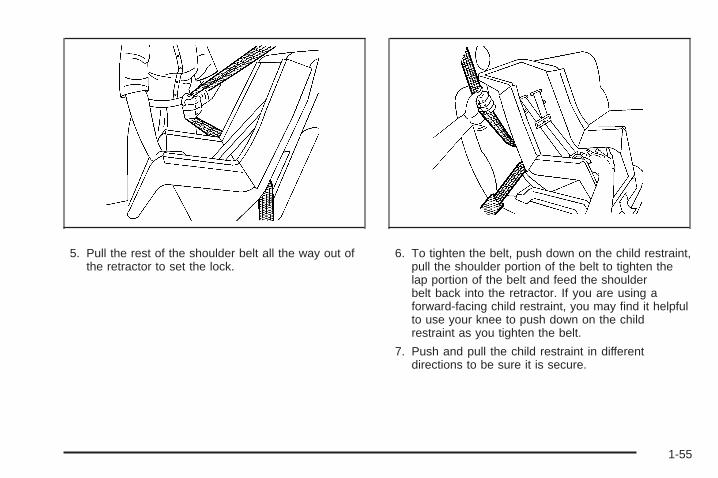
5. Pull the rest of the shoulder belt all the way out ofthe retractor to set the lock.
1-51
6. To tighten the belt, push down on the child restraint,pull the shoulder portion of the belt to tighten thelap portion of the belt and feed the shoulderbelt back into the retractor. If you are using aforward-facing child restraint, you may find it helpfulto use your knee to push down on the childrestraint as you tighten the belt.
7. Push and pull the child restraint in differentdirections to be sure it is secure.
To remove the child restraint, unbuckle the vehicle’ssafety belt and let it go back all the way. If the top tetheris attached to a top tether anchor, disconnect it.
Securing a Child Restraint in theCenter Front Seat Position
{CAUTION:
A child in a child restraint in the center frontseat can be badly injured or killed by thefrontal airbags if they inflate. Never secure achild restraint in the center front seat. It isalways better to secure a child restraint in arear seat.
Do not use child restraints in the center front seatposition.
1-52
Securing a Child Restraint in theRight Front Seat PositionYour vehicle has airbags. A rear seat is a safer place tosecure a forward-facing child restraint. See Where toPut the Restraint on page 1-42.
In addition, your vehicle has a passenger sensing systemwhich is designed to turn off the right front passenger’sfrontal airbag under certain conditions. See PassengerSensing System on page 1-64 and Passenger AirbagStatus Indicator on page 3-34 for more information onthis, including important safety information.
A label on your sun visor says, “Never put a rear-facingchild seat in the front.” This is because the risk to therear-facing child is so great, if the airbag deploys.
{CAUTION:
A child in a rear-facing child restraint can beseriously injured or killed if the right frontpassenger’s airbag inflates. This is becausethe back of the rear-facing child restraintwould be very close to the inflating airbag.
CAUTION: (Continued)
CAUTION: (Continued)
Even though the passenger sensing system isdesigned to turn off the right front passenger’sfrontal airbag if the system detects arear-facing child restraint, no system isfail-safe, and no one can guarantee that anairbag will not deploy under some unusualcircumstance, even though it is turned off. Werecommend that rear-facing child restraints besecured in a rear seat, even if the airbag is off.
If you secure a forward-facing child restraint inthe right front seat, always move the frontpassenger seat as far back as it will go. It isbetter to secure the child restraint in a rear seat.
See Passenger Sensing System on page 1-64for additional information.
If your child restraint has the LATCH system, see LowerAnchors and Tethers for Children (LATCH) onpage 1-43 for how to install your child restraint usingLATCH. If you secure a child restraint using a safety beltand it uses a top tether, see Lower Anchors andTethers for Children (LATCH) on page 1-43 for toptether anchor locations.
1-53
Do not secure a child seat in a position without a toptether anchor if a national or local law requires that thetop tether be anchored, or if the instructions thatcome with the child restraint say that the top strap mustbe anchored.
In Canada, the law requires that forward-facing childrestraints have a top tether, and that the tether beattached.
You will be using the lap-shoulder belt to secure thechild restraint in this position. Follow the instructions thatcame with the child restraint.
1. Move the seat as far back as it will go beforesecuring the forward-facing child restraint.When the passenger sensing system has turned offthe right front passenger’s frontal airbag, the offindicator on the passenger airbag status indicatorshould light and stay lit when you start thevehicle. See Passenger Airbag Status Indicator onpage 3-34.
2. Put the child restraint on the seat.
3. Pick up the latch plate, and run the lap and shoulderportions of the vehicle’s safety belt through oraround the restraint. The child restraint instructionswill show you how.
4. Push the latch plate into the buckle until it clicks.Make sure the release button is positioned so youwould be able to unbuckle the safety belt quicklyif necessary.
1-54
5. Pull the rest of the shoulder belt all the way out ofthe retractor to set the lock.
6. To tighten the belt, push down on the child restraint,pull the shoulder portion of the belt to tighten thelap portion of the belt and feed the shoulderbelt back into the retractor. If you are using aforward-facing child restraint, you may find it helpfulto use your knee to push down on the childrestraint as you tighten the belt.
7. Push and pull the child restraint in differentdirections to be sure it is secure.
1-55
If the airbag is off, the off indicator in the passengerairbag status indicator will come on and stay on whenthe vehicle is started.
If a child restraint has been installed and the onindicator is lit, turn the vehicle off. Remove the childrestraint from the vehicle and reinstall the child restraint.
If, after reinstalling the child restraint and restartingthe vehicle, the on indicator is still lit, check to makesure that the vehicle’s seatback is not pressing the childrestraint into the seat cushion. If this happens, slightlyrecline the vehicle’s seatback and adjust the seatcushion if possible. Also make sure the child restraint isnot trapped under the vehicle head restraint. If thishappens, adjust the head restraint.
Remove any additional material from the seat such asblankets, cushions, seat covers, seat heaters or seatmassagers before reinstalling or securing the childrestraint.
If the on indicator is still lit, secure the child in the childrestraint in a rear seat position in the vehicle andcheck with your dealer/retailer.
To remove the child restraint, unbuckle the vehicle’ssafety belt and let it go back all the way.
Airbag SystemYour vehicle has the following airbags:
• A frontal airbag for the driver.
• A frontal airbag for the right front passenger.
Your vehicle may have the following airbags:
• A roof-rail airbag for the driver and the passengerseated directly behind the driver.
• A roof-rail airbag for the right front passenger andthe person seated directly behind the right frontpassenger.
All of the airbags in your vehicle will have the wordAIRBAG embossed in the trim or on an attached labelnear the deployment opening.
For frontal airbags, the word AIRBAG will appear on themiddle part of the steering wheel for the driver andon the instrument panel for the right front passenger.
With roof-rail airbags, the word AIRBAG will appearalong the headliner or trim.
1-56
Airbags are designed to supplement the protectionprovided by safety belts. Even though today’s airbagsare also designed to help reduce the risk of injuryfrom the force of an inflating bag, all airbags must inflatevery quickly to do their job.
Here are the most important things to know about theairbag system:
{CAUTION:
You can be severely injured or killed in a crashif you are not wearing your safety belt — evenif you have airbags. Wearing your safety beltduring a crash helps reduce your chance ofhitting things inside the vehicle or beingejected from it. Airbags are “supplementalrestraints” to the safety belts. All airbags aredesigned to work with safety belts, but do notreplace them.
{CAUTION:
Frontal airbags are designed to deploy inmoderate to severe frontal and near frontalcrashes. They are not designed to inflate inrollover, rear crashes, or in many side crashes.
If your vehicle has rollover capable roof-railairbags, they are designed to inflate inmoderate to severe crashes where somethinghits the side of your vehicle, during a vehiclerollover, or in a severe frontal impact. They arenot designed to inflate in rear crashes.
Everyone in your vehicle should wear a safetybelt properly — whether or not there is anairbag for that person.
1-57
{CAUTION:
Airbags inflate with great force, faster than theblink of an eye. Anyone who is up against, orvery close to, any airbag when it inflates canbe seriously injured or killed. Do not situnnecessarily close to the airbag, as youwould be if you were sitting on the edge ofyour seat or leaning forward. Safety belts helpkeep you in position before and during acrash. Always wear your safety belt, even withairbags. The driver should sit as far back aspossible while still maintaining control of thevehicle.
Occupants should not lean on or sleep againstthe door or side windows in seating positionswith roof-rail airbags.
{CAUTION:
Airbags plus lap-shoulder belts offer the bestprotection for adults, but not for youngchildren and infants. Neither the vehicle’ssafety belt system nor its airbag system isdesigned for them. Young children and infantsneed the protection that a child restraintsystem can provide. Always secure childrenproperly in your vehicle. To read how, seeOlder Children on page 1-34 or Infants andYoung Children on page 1-36.
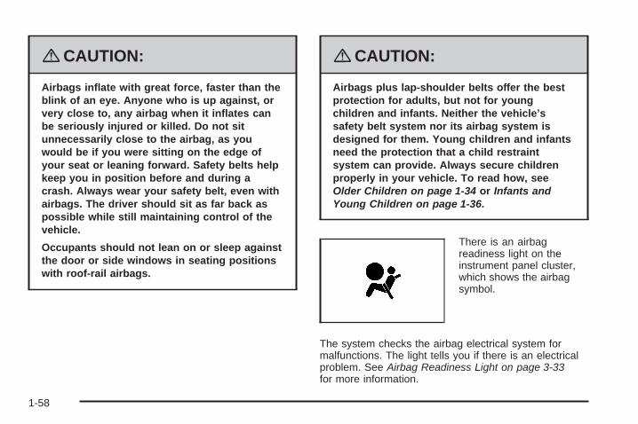
There is an airbagreadiness light on theinstrument panel cluster,which shows the airbagsymbol.
The system checks the airbag electrical system formalfunctions. The light tells you if there is an electricalproblem. See Airbag Readiness Light on page 3-33for more information.
1-58
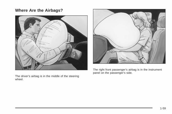
Where Are the Airbags?
The driver’s airbag is in the middle of the steeringwheel.
The right front passenger’s airbag is in the instrumentpanel on the passenger’s side.
1-59
If your vehicle has roof-rail airbags for the driver, rightfront passenger, and second row outboard passengers,they are in the ceiling above the side windows.
{CAUTION:
If something is between an occupant and anairbag, the airbag might not inflate properly orit might force the object into that personcausing severe injury or even death. The pathof an inflating airbag must be kept clear. Donot put anything between an occupant and anairbag, and do not attach or put anything onthe steering wheel hub or on or near any otherairbag covering.
If your vehicle has roof-rail airbags, neversecure anything to the roof of your vehicle byrouting the rope or tie down through any dooror window opening. If you do, the path of aninflating roof-rail airbag will be blocked.
Driver Side shown, Passenger Side similar
1-60
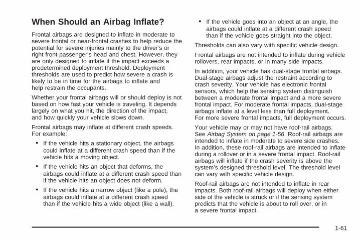
When Should an Airbag Inflate?Frontal airbags are designed to inflate in moderate tosevere frontal or near-frontal crashes to help reduce thepotential for severe injuries mainly to the driver’s orright front passenger’s head and chest. However, theyare only designed to inflate if the impact exceeds apredetermined deployment threshold. Deploymentthresholds are used to predict how severe a crash islikely to be in time for the airbags to inflate andhelp restrain the occupants.
Whether your frontal airbags will or should deploy is notbased on how fast your vehicle is traveling. It dependslargely on what you hit, the direction of the impact,and how quickly your vehicle slows down.
Frontal airbags may inflate at different crash speeds.For example:
• If the vehicle hits a stationary object, the airbagscould inflate at a different crash speed than if thevehicle hits a moving object.
• If the vehicle hits an object that deforms, theairbags could inflate at a different crash speed thanif the vehicle hits an object does not deform.
• If the vehicle hits a narrow object (like a pole), theairbags could inflate at a different crash speedthan if the vehicle hits a wide object (like a wall).
• If the vehicle goes into an object at an angle, theairbags could inflate at a different crash speedthan if the vehicle goes straight into the object.
Thresholds can also vary with specific vehicle design.
Frontal airbags are not intended to inflate during vehiclerollovers, rear impacts, or in many side impacts.
In addition, your vehicle has dual-stage frontal airbags.Dual-stage airbags adjust the restraint according tocrash severity. Your vehicle has electronic frontalsensors, which help the sensing system distinguishbetween a moderate frontal impact and a more severefrontal impact. For moderate frontal impacts, dual-stageairbags inflate at a level less than full deployment.For more severe frontal impacts, full deployment occurs.
Your vehicle may or may not have roof-rail airbags.See Airbag System on page 1-56. Roof-rail airbags areintended to inflate in moderate to severe side crashes.In addition, these roof-rail airbags are intended to inflateduring a rollover or in a severe frontal impact. Roof-railairbags will inflate if the crash severity is above thesystem’s designed threshold level. The threshold levelcan vary with specific vehicle design.
Roof-rail airbags are not intended to inflate in rearimpacts. Both roof-rail airbags will deploy when eitherside of the vehicle is struck or if the sensing systempredicts that the vehicle is about to roll over, or ina severe frontal impact.
1-61
Your vehicle has a seat position sensor which enablesthe sensing system to monitor the position of thedriver’s seat. The seat position sensor providesinformation that is used to determine if the airbagsshould deploy at a reduced level or at full deployment.
In any particular crash, no one can say whether anairbag should have inflated simply because of thedamage to a vehicle or because of what the repair costswere. For frontal airbags, inflation is determined bywhat the vehicle hits, the angle of the impact, and howquickly the vehicle slows down. For roof-rail airbags,deployment is determined by the location and severity ofthe side impact. In a rollover event, roof-rail airbagdeployment is determined by the direction of the roll.
What Makes an Airbag Inflate?In a deployment event, the sensing system sends anelectrical signal triggering a release of gas fromthe inflator. Gas from the inflator fills the airbag causingthe bag to break out of the cover and deploy. Theinflator, the airbag, and related hardware are all part ofthe airbag module.
Frontal airbag modules are located inside the steeringwheel and instrument panel. For vehicles withroof-rail airbags, there are airbag modules in the ceilingof the vehicle, near the side windows that haveoccupant seating positions.
How Does an Airbag Restrain?In moderate to severe frontal or near frontal collisions,even belted occupants can contact the steering wheel orthe instrument panel. In moderate to severe sidecollisions, even belted occupants can contact the insideof the vehicle.
Airbags supplement the protection provided by safetybelts. Frontal airbags distribute the force of theimpact more evenly over the occupant’s upper body,stopping the occupant more gradually. Roof-rail airbagsdistribute the force of the impact more evenly overthe occupant’s upper body.
Rollover capable roof-rail airbags are designed to helpcontain the head and chest of occupants in theoutboard seating positions in the first and second rows.The rollover capable roof-rail airbags are designed tohelp reduce the risk of full or partial ejection in rolloverevents, although no system can prevent all suchejections.
But airbags would not help in many types of collisions,primarily because the occupant’s motion is nottoward those airbags. See When Should an AirbagInflate? on page 1-61 for more information.
Airbags should never be regarded as anything morethan a supplement to safety belts.
1-62
What Will You See After an AirbagInflates?After the frontal airbags inflate, they quickly deflate, soquickly that some people may not even realize anairbag inflated. Roof-rail airbags may still be at leastpartially inflated for some time after they deploy. Somecomponents of the airbag module may be hot forseveral minutes. For location of the airbag modules, seeWhat Makes an Airbag Inflate? on page 1-62.
The parts of the airbag that come into contact with youmay be warm, but not too hot to touch. There maybe some smoke and dust coming from the vents in thedeflated airbags. Airbag inflation does not preventthe driver from seeing out of the windshield or beingable to steer the vehicle, nor does it prevent people fromleaving the vehicle.
{CAUTION:
When an airbag inflates, there may be dust inthe air. This dust could cause breathingproblems for people with a history of asthmaor other breathing trouble. To avoid this,everyone in the vehicle should get out as soonas it is safe to do so. If you have breathingproblems but cannot get out of the vehicleafter an airbag inflates, then get fresh air byopening a window or a door. If you experiencebreathing problems following an airbagdeployment, you should seek medicalattention.
Your vehicle has a feature that may automaticallyunlock the doors, turn the interior lamps on, and turnthe hazard warning flashers on when the airbags inflate.You can lock the doors, turn the interior lamps off,and turn the hazard warning flashers off by using thecontrols for those features.
1-63
In many crashes severe enough to inflate the airbag,windshields are broken by vehicle deformation.Additional windshield breakage may also occur from theright front passenger airbag.
• Airbags are designed to inflate only once. After anairbag inflates, you will need some new parts forthe airbag system. If you do not get them, the airbagsystem will not be there to help protect you inanother crash. A new system will include airbagmodules and possibly other parts. The servicemanual for your vehicle covers the need to replaceother parts.
• Your vehicle has a crash sensing and diagnosticmodule which records information after a crash.See Vehicle Data Recording and Privacy onpage 7-16 and Event Data Recorders on page 7-17.
• Let only qualified technicians work on the airbagsystems. Improper service can mean that anairbag system will not work properly. See yourdealer/retailer for service.
Passenger Sensing SystemYour vehicle has a passenger sensing system for theright front passenger’s position. The passengerairbag status indicator will be visible on the overheadconsole when you start your vehicle.
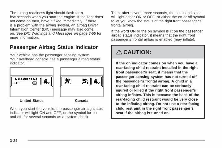
The words ON and OFF, or the symbol for on and off,will be visible during the system check. When thesystem check is complete, either the word ON or theword OFF, or the symbol for on or the symbol for off, willbe visible. See Passenger Airbag Status Indicator onpage 3-34.
The passenger sensing system will turn off the rightfront passenger’s frontal airbag under certain conditions.The driver’s airbags are not part of the passengersensing system.
United States Canada
1-64
The passenger sensing system works with sensors thatare part of the right front passenger’s seat and safetybelt. The sensors are designed to detect the presence ofa properly-seated occupant and determine if the rightfront passenger’s frontal airbag should be enabled (mayinflate) or not.
Accident statistics show that children are safer if theyare restrained in the rear rather than the front seat.
We recommend that children be secured in a rear seat,including: an infant or a child riding in a rear-facingchild restraint; a child riding in a forward-facing childseat; an older child riding in a booster seat; and children,who are large enough, using safety belts.
A label on your sun visor says, “Never put a rear-facingchild seat in the front.” This is because the risk to therear-facing child is so great, if the airbag deploys.
{CAUTION:
A child in a rear-facing child restraint can beseriously injured or killed if the right frontpassenger’s airbag inflates. This is becausethe back of the rear-facing child restraintwould be very close to the inflating airbag.
Even though the passenger sensing system isdesigned to turn off the right front passenger’sfrontal airbag if the system detects arear-facing child restraint, no system isfail-safe, and no one can guarantee that anairbag will not deploy under some unusualcircumstance, even though it is turned off. Werecommend that rear-facing child restraints besecured in a rear seat, even if the airbag is off.
If you secure a forward-facing child restraint inthe right front seat, always move the frontpassenger seat as far back as it will go. It isbetter to secure the child restraint in a rear seat.
1-65
The passenger sensing system is designed to turn offthe right front passenger’s frontal airbag if:
• The right front passenger seat is unoccupied.
• The system determines that an infant is present ina rear-facing infant seat.
• The system determines that a small child is presentin a child restraint.
• The system determines that a small child is presentin a booster seat.
• A right front passenger takes his/her weight off ofthe seat for a period of time.
• The right front passenger seat is occupied by asmaller person, such as a child who has outgrownchild restraints.
• Or, if there is a critical problem with the airbagsystem or the passenger sensing system.
When the passenger sensing system has turned off theright front passenger’s frontal airbag, the off indicatorwill light and stay lit to remind you that the airbag is off.See Passenger Airbag Status Indicator on page 3-34.
If a child restraint has been installed and the on indicatoris lit, turn the vehicle off. Remove the child restraintfrom the vehicle and reinstall the child restraint followingthe child restraint manufacturer’s directions and referto Securing a Child Restraint in the Right FrontSeat Position on page 1-53.
If, after reinstalling the child restraint and restarting thevehicle, the on indicator is still lit, check to makesure that the vehicle’s seatback is not pressing the childrestraint into the seat cushion. If this happens, slightlyrecline the vehicle’s seatback and adjust the seatcushion if possible. Also make sure the child restraint isnot trapped under the vehicle head restraint. If thishappens, adjust the head restraint. See Head Restraintson page 1-10.
1-66
Remove any additional material from the seat such asblankets, cushions, seat covers, seat heaters, or seatmassagers before reinstalling or securing the childrestraint.
If the on indicator is still lit, secure the child in the childrestraint in a rear seat position in the vehicle, andcheck with your dealer/retailer.
The passenger sensing system is designed to enable(may inflate) the right front passenger’s frontalairbag anytime the system senses that a person of adultsize is sitting properly in the right front passenger’sseat. When the passenger sensing system has allowedthe airbag to be enabled, the on indicator will lightand stay lit to remind you that the airbag is active.
For some children who have outgrown child restraintsand for very small adults, the passenger sensing systemmay or may not turn off the right front passenger’sfrontal airbag, depending upon the person’s seating
posture and body build. Everyone in your vehicle whohas outgrown child restraints should wear a safetybelt properly — whether or not there is an airbag for thatperson.
If a person of adult-size is sitting in the right frontpassenger’s seat, but the off indicator is lit, it could bebecause that person is not sitting properly in the seat. Ifthis happens, turn the vehicle off, remove any additionalmaterial from the seat, such as blankets, cushions,seat covers, seat heaters or seat massagers and askthe person to place the seatback in the fully uprightposition, then sit upright in the seat, centered on the seatcushion, with the person’s legs comfortably extended.Restart the vehicle and have the person remain inthis position for two to three minutes. This will allow thesystem to detect that person and then enable theright front passenger’s frontal airbag.
1-67
Safety belts help keep the passenger in position on theseat during vehicle maneuvers and braking, whichhelps the passenger sensing system maintain thepassenger airbag status. See “Safety Belts” and “ChildRestraints” in the Index for additional informationabout the importance of proper restraint use.
If you ever pull the shoulder portion of the belt out allthe way, you will engage the child restraint lockingfeature. This may unintentionally cause the passengersensing system to turn the airbag(s) off for someadult size occupants. If this happens, just let the belt goback all the way and start again.
{CAUTION:
If the airbag readiness light in the instrumentpanel cluster ever comes on and stays on, itmeans that something may be wrong with theairbag system. If this ever happens, have thevehicle serviced promptly, because anadult-size person sitting in the right frontpassenger’s seat may not have the protectionof the airbag(s). See Airbag Readiness Lighton page 3-33 for more on this, includingimportant safety information.
1-68
A thick layer of additional material, such as a blanket orcushion, or aftermarket equipment such as seatcovers, seat heaters, and seat massagers can affecthow well the passenger sensing system operates.We recommend that you not use seat covers or otheraftermarket equipment other than any that GM hasapproved for your specific vehicle. See AddingEquipment to Your Airbag-Equipped Vehicle onpage 1-70 for more information about modifications thatcan affect how the system operates.
{CAUTION:
Stowing of articles under the passenger’s seator between the passenger’s seat cushion andseatback may interfere with the properoperation of the passenger sensing system.
Servicing Your Airbag-EquippedVehicleAirbags affect how your vehicle should be serviced.There are parts of the airbag system in several placesaround your vehicle. Your dealer/retailer and the servicemanual have information about servicing your vehicleand the airbag system. To purchase a service manual,see Service Publications Ordering Information onpage 7-15.
{CAUTION:
For up to 10 seconds after the ignition isturned off and the battery is disconnected, anairbag can still inflate during improper service.You can be injured if you are close to anairbag when it inflates. Avoid yellowconnectors. They are probably part of theairbag system. Be sure to follow properservice procedures, and make sure the personperforming work for you is qualified to do so.
1-69
Adding Equipment to YourAirbag-Equipped Vehicle
Q: Is there anything I might add to or changeabout the vehicle that could keep the airbagsfrom working properly?
A: Yes. If you add things that change your vehicle’sframe, bumper system, height, front end or sidesheet metal, they may keep the airbag system fromworking properly. Changing or moving any partsof the front seats, safety belts, the airbag sensingand diagnostic module, steering wheel, instrumentpanel, roof-rail airbag modules, ceiling headlineror pillar garnish trim, overhead console, frontsensors, side impact sensors, rollover sensormodule, or airbag wiring can affect the operation ofthe airbag system.
In addition, your vehicle has a passenger sensingsystem for the right front passenger’s position,which includes sensors that are part of thepassenger’s seat. The passenger sensing system
may not operate properly if the original seat trim isreplaced with non-GM covers, upholstery ortrim, or with GM covers, upholstery or trim designedfor a different vehicle. Any object, such as anaftermarket seat heater or a comfort enhancing pador device, installed under or on top of the seatfabric, could also interfere with the operation of thepassenger sensing system. This could eitherprevent proper deployment of the passengerairbag(s) or prevent the passenger sensing systemfrom properly turning off the passenger airbag(s).See Passenger Sensing System on page 1-64.
If you have any questions about this, you shouldcontact Customer Assistance before you modifyyour vehicle. The phone numbers and addresses forCustomer Assistance are in Step Two of theCustomer Satisfaction Procedure in this manual.See Customer Satisfaction Procedure on page 7-2.
If your vehicle has rollover roof-rail airbags, seeDifferent Size Tires and Wheels on page 5-72for additional important information.
1-70
Q: Because I have a disability, I have to get myvehicle modified. How can I find out whetherthis will affect my airbag system?
A: If you have questions, call Customer Assistance.The phone numbers and addresses for CustomerAssistance are in Step Two of the CustomerSatisfaction Procedure in this manual. SeeCustomer Satisfaction Procedure on page 7-2.
In addition, your dealer/retailer and the service manualhave information about the location of the airbagsensors, sensing and diagnostic module and airbagwiring.
Restraint System Check
Checking the Restraint Systems
Safety BeltsNow and then, make sure the safety belt reminder lightand all your belts, buckles, latch plates, retractorsand anchorages are working properly.
Look for any other loose or damaged safety belt systemparts. If you see anything that might keep a safetybelt system from doing its job, have it repaired.
Torn or frayed safety belts may not protect you in acrash. They can rip apart under impact forces. If a beltis torn or frayed, get a new one right away.
Make sure the safety belt reminder light is working. SeeSafety Belt Reminders on page 3-32 for moreinformation.
Keep safety belts clean and dry. See Care of SafetyBelts on page 5-99.
AirbagsThe airbag system does not need regularly scheduledmaintenance or replacement. Make sure the airbagreadiness light is working. See Airbag Readiness Lighton page 3-33 for more information.
Notice: If an airbag covering is damaged, opened,or broken, the airbag may not work properly. Donot open or break the airbag coverings. If there areany opened or broken airbag covers, have theairbag covering and/or airbag module replaced. Forthe location of the airbag modules, see WhatMakes an Airbag Inflate? on page 1-62. See yourdealer/retailer for service.
1-71
Replacing Restraint System PartsAfter a Crash
{CAUTION:
A crash can damage the restraint systems inyour vehicle. A damaged restraint system maynot properly protect the person using it,resulting in serious injury or even death in acrash. To help make sure your restraintsystems are working properly after a crash,have them inspected and any necessaryreplacements made as soon as possible.
If you have had a crash, do you need new belts orLATCH system (if equipped) parts?
After a very minor crash, nothing may be necessary.But the belt assemblies that were used during any crashmay have been stressed or damaged. See yourdealer/retailer to have your safety belt assembliesinspected or replaced.
If your vehicle has the LATCH system and it was beingused during a crash, you may need new LATCHsystem parts.
New parts and repairs may be necessary even if thebelt or LATCH system (if equipped), was not being usedat the time of the crash.
If an airbag inflates, you will need to replace airbagsystem parts. See the part on the airbag system earlierin this section.
Have your safety belt pretensioners checked if yourvehicle has been in a crash, if your airbag readinesslight stays on after you start your vehicle, or while youare driving. See Airbag Readiness Light on page 3-33.
1-72
Keys ...............................................................2-3Remote Keyless Entry (RKE) System ................2-4Remote Keyless Entry (RKE) System
Doors and Locks ............................................2-10Door Locks ..................................................2-10Power Door Locks ........................................2-10Delayed Locking ...........................................2-10Programmable Automatic Door Locks ..............2-11Rear Door Security Locks ..............................2-11Lockout Protection ........................................2-12Midgate® .....................................................2-12Tailgate .......................................................2-22Power Running Boards ..................................2-22
Windows ........................................................2-23Power Windows ............................................2-24Sun Visors ...................................................2-25
Theft-Deterrent Systems ..................................2-26Content Theft-Deterrent .................................2-26PASS-Key® III+ ............................................2-27PASS-Key® III+ Operation ..............................2-28
Starting and Operating Your Vehicle ................2-29New Vehicle Break-In ....................................2-29Ignition Positions ..........................................2-30
Retained Accessory Power (RAP) ...................2-31Starting the Engine .......................................2-31Adjustable Throttle and Brake Pedal ................2-33Engine Coolant Heater ..................................2-33Active Fuel Management™ .............................2-35Automatic Transmission Operation ...................2-35Tow/Haul Mode ............................................2-39Four-Wheel Drive ..........................................2-39Parking Brake ..............................................2-45Shifting Into PARK (P) ...................................2-46Shifting Out of PARK (P) ...............................2-48Parking Over Things That Burn .......................2-48Engine Exhaust ............................................2-49Running the Engine While Parked ...................2-50
Mirrors ...........................................................2-51Automatic Dimming Rearview Mirror with
OnStar®, Compass and TemperatureDisplay ....................................................2-51
Automatic Dimming Rearview Mirror withCompass and Temperature Display ..............2-53
Outside Power Mirrors ...................................2-55Outside Power Foldaway Mirrors .....................2-57
Object Detection Systems ...............................2-59Ultrasonic Rear Parking Assist (URPA) ............2-59
OnStar® System .............................................2-61
Section 2 Features and Controls
2-1
Universal Home Remote System ......................2-64Universal Home Remote System .....................2-64Universal Home Remote System Operation
(With Three Round LED) ............................2-65Storage Areas ................................................2-71
Leaving children in a vehicle with the ignitionkey is dangerous for many reasons, childrenor others could be badly injured or even killed.They could operate the power windows orother controls or even make the vehicle move.The windows will function with the keys in theignition and they could be seriously injured orkilled if caught in the path of a closingwindow. Do not leave the keys in a vehiclewith children.
The key can be used for the ignition, all door locks,tailgate, and side storage boxes.
See your dealer/retailer if a replacement key oradditional key is needed.
Notice: If you ever lock your keys in your vehicle,you may have to damage the vehicle to get in.Be sure you have spare keys.
If you are locked out of your vehicle, contact roadsideassistance. See Roadside Assistance Program onpage 7-7 for more information.
2-3
Remote Keyless Entry (RKE)SystemYour Remote Keyless Entry (RKE) system operates ona radio frequency subject to Federal CommunicationsCommission (FCC) Rules and with Industry Canada.
This device complies with Part 15 of the FCC Rules.Operation is subject to the following two conditions:
1. This device may not cause interference.
2. This device must accept any interference received,including interference that may cause undesiredoperation of the device.
This device complies with RSS-210 of Industry Canada.Operation is subject to the following two conditions:
1. This device may not cause interference.
2. This device must accept any interference received,including interference that may cause undesiredoperation of the device.
Changes or modifications to this system by other thanan authorized service facility could void authorization touse this equipment.
At times you may notice a decrease in operating range.This is normal for any RKE system. If the transmitterdoes not work or if you have to stand closer toyour vehicle for the transmitter to work, try this:
• Check the distance. You may be too far from yourvehicle. You may need to stand closer duringrainy or snowy weather.
• Check the location. Other vehicles or objects maybe blocking the signal. Take a few steps to theleft or right, hold the transmitter higher, andtry again.
• Check to determine if battery replacement isnecessary. See “Battery Replacement” later in thissection.
• If you are still having trouble, see your dealer/retaileror a qualified technician for service.
Remote Keyless Entry (RKE)System OperationThe vehicle’s doors can be locked and unlocked fromabout 3 feet (1 m) up to 65 feet (20 m) away withthe Remote Keyless Entry (RKE) transmitter.
2-4
If your vehicle has the remote start feature you can alsostart your vehicle with the RKE transmitter. The RKEtransmitter, with the remote start button, providesan increased operating range of 195 feet (60 m) away.However, the operating range may be less while thevehicle is running. As a result, you may need tobe closer to your vehicle to turn it off than you were tostart it.
There are other conditions which can affect theperformance of the transmitter. See Remote KeylessEntry (RKE) System on page 2-4.
/ (Remote Vehicle Start): If your vehicle has thisfeature, press / to start the engine from outside thevehicle using the RKE transmitter. See RemoteVehicle Start on page 2-7 for additional information.
Q (Lock): Press Q to lock all the doors, includingthe tailgate.
If enabled through the Driver Information Center (DIC),the turn signal lamps will flash once to indicatelocking has occurred. If enabled through the DIC, thehorn will chirp when Q is pressed again withinthree seconds of the previous press of the lock button.See DIC Vehicle Customization (With DIC Buttons)on page 3-63 for additional information.
Pressing Q will arm the content theft-deterrent system.See Content Theft-Deterrent on page 2-26.
" (Unlock): Press " to unlock the driver’s door. If " ispressed again within three seconds, all remainingdoors, including the tailgate, will unlock.
With Remote Start(Without Remote Start
Similar)
2-5
If it is dark enough outside, your interior lamps willcome on and stay on for 20 seconds or until the ignitionis turned on. If enabled through the DIC, the turnsignal lamps will flash twice to indicate unlocking hasoccurred. See DIC Vehicle Customization (WithDIC Buttons) on page 3-63. If enabled through the DIC,the exterior lights will turn on briefly if it is darkenough outside. See “APPROACH LIGHTING” underDIC Vehicle Customization (With DIC Buttons) onpage 3-63.
Pressing " on the RKE transmitter will disarm thecontent theft-deterrent system. See ContentTheft-Deterrent on page 2-26.
L (Vehicle Locator/Panic Alarm): Press andrelease L to locate your vehicle. The turn signal lampswill flash and the horn will sound three times.
Press and hold L for more than two seconds toactivate the panic alarm. The turn signal lamps will flashand the horn will sound repeatedly for 30 seconds.The alarm will turn off when the ignition is movedto ON/RUN or L is pressed again. The ignition mustbe in LOCK/OFF for the panic alarm to work.
Matching Transmitter(s) to YourVehicleEach RKE transmitter is coded to prevent anothertransmitter from unlocking your vehicle. If a transmitteris lost or stolen, a replacement can be purchasedthrough your dealer/retailer. All transmitters need to bere-coded to match the new transmitter. The losttransmitter will no longer work after the new transmittersare re-coded. The vehicle can have a maximum ofeight transmitters matched to it. See “Relearn RemoteKey” under DIC Operation and Displays (With DICButtons) on page 3-48 or DIC Operation and Displays(Without DIC Buttons) on page 3-53 for instructionson how to match RKE transmitters to your vehicle.
Battery ReplacementReplace the battery if the REPLACE BATTERY INREMOTE KEY message displays in the DIC. See“REPLACE BATTERY IN REMOTE KEY” under DICWarnings and Messages on page 3-55 for additionalinformation.
Notice: When replacing the battery, use care not totouch any of the circuitry. Static from your bodytransferred to these surfaces may damage thetransmitter.
2-6
To replace the battery in the RKE transmitter:
1. Separate the halves of the transmitter with a flat,thin object inserted into the notch on the side.
2. Remove the old battery. Do not use a metal object.
3. Insert the new battery, positive side facing down.Replace with a CR2032 or equivalent battery.
4. Put the transmitter back together tightly.
Remote Vehicle StartYour vehicle may have a remote starting feature. Thisfeature allows you to start the engine from outside of thevehicle. It may also start up the vehicle’s heating orair conditioning systems and rear window defogger.Normal operation of the system will return after the keyis turned to the ON/RUN position.
If your vehicle has an automatic climate control system,the climate control system will default to a heating orcooling mode depending on the outside temperatures. Ifyour vehicle does not have an automatic climate controlsystem, the system will turn on at the setting the vehiclewas set to when the vehicle was last turned off.
During a remote start, if your vehicle has an automaticclimate control system and heated seats, the heatedseats will turn on during colder outside temperatures andwill shut off when the key is turned to ON/RUN. Ifyour vehicle does not have an automatic climate controlsystem, during remote start, you will need to manuallyturn the heated seats on and off. See Heated Seatson page 1-5 for additional information.
Laws in some communities may restrict the use ofremote starters. For example, some laws may require aperson using the remote start to have the vehicle inview when doing so. Check local regulations forany requirements on remote starting of vehicles.
2-7
Do not use the remote start feature if your vehicle is lowon fuel. Your vehicle may run out of fuel.
The RKE transmitter with the remote start button,provides an increased range of operation. However, therange may be less while the vehicle is running. As aresult, you may need to be closer to your vehicle to turnit off, than you were to turn it on.
There are other conditions which can affect theperformance of the transmitter, see Remote KeylessEntry (RKE) System on page 2-4 for additionalinformation.
/ (Remote Start): This button will be on the RKEtransmitter if you have remote start.
To start the vehicle using the remote start feature:
1. Aim the transmitter at the vehicle.
2. Press and release the transmitter’s lock button. Thevehicle’s doors will lock. Immediately press andhold the transmitter’s remote start button until theturn signal lights flash. If you cannot see thevehicle’s lights, press and hold the remote startbutton for two to four seconds. Pressing the remotestart button again after the vehicle has startedwill turn the engine off.
When the vehicle starts, the parking lamps will turnon and remain on while the vehicle is running.If the vehicle is left running it will automatically shutoff after 10 minutes unless a time extension hasbeen done.
3. If it is the first remote start since the vehicle hasbeen driven, repeat these steps, while the engine isstill running, to extend the engine running time by10 minutes. Remote start can be extended one time.
After entering the vehicle during a remote start, insertand turn the key to RUN to drive the vehicle.
To manually shut off a remote start, do any of thefollowing:
• Aim the RKE transmitter at the vehicle and pressthe remote start button until the parking lampsturn off.
• Turn on the hazard warning flashers.
• Turn the ignition switch on and then off.
The vehicle can be remote started two separate timesbetween driving sequences. The engine will run for10 minutes after each remote start.
Or, you can extend the engine run time by another10 minutes within the first 10 minute remote start timeframe, and before the engine stops.
2-8
For example, if the lock button and then the remotestart buttons are pressed again after the vehiclehas been running for five minutes, 10 minutes areadded, allowing the engine to run for 15 minutes.
The additional ten minutes are considered a secondremote vehicle start.
Once two remote starts, or a single remote start withone time extension has been done, the vehicle must bestarted with the key.
After the key is removed from the ignition, the vehiclecan be remote started again.
The vehicle cannot be remote started if the key is in theignition, the hood is not closed, or if there is anemission control system malfunction and the checkengine light comes on.
Also, the engine will turn off during a remote vehiclestart if the coolant temperature gets too high or if the oilpressure gets low.
Vehicles that have the remote vehicle start feature areshipped from the factory with the remote vehiclestart system enabled. The system may be enabled ordisabled through the DIC. See “REMOTE START” underDIC Vehicle Customization (With DIC Buttons) onpage 3-63 for additional information. If your vehicle doesnot have DIC buttons, see your dealer/retailer toenable or disable the remote vehicle start system.
Remote Start ReadyIf your vehicle does not have the remote vehicle startfeature, it may have the remote start ready feature. Thisfeature allows your dealer/retailer to add themanufacturer’s remote vehicle start feature.
If your vehicle has the remote start ready feature, theRKE transmitter will have an extended range that allowslocking or unlocking of the vehicle from approximately197 feet (60 m) away.
See your dealer/retailer if you would like to add themanufacturer’s remote vehicle start feature to yourvehicle.
2-9
Doors and Locks
Door Locks
{CAUTION:
Unlocked doors can be dangerous.• Passengers, especially children, can easily
open the doors and fall out of a movingvehicle. When a door is locked, the handlewill not open it. You increase the chanceof being thrown out of the vehicle in acrash if the doors are not locked. So, wearsafety belts properly and lock the doorswhenever you drive.
• Young children who get into unlockedvehicles may be unable to get out. A childcan be overcome by extreme heat and cansuffer permanent injuries or even deathfrom heat stroke. Always lock your vehiclewhenever you leave it.
• Outsiders can easily enter through anunlocked door when you slow down orstop your vehicle. Locking your doors canhelp prevent this from happening.
There are several ways to lock and unlock the doors.
To lock or unlock the door from the outside, usethe remote keyless entry (RKE) transmitter or the key.
To lock or unlock the door from the inside, slide themanual lever up or down, or use the power door locksswitch.
Power Door LocksThe power door lock switches are located on thefront doors.
K (Unlock): Press to unlock the doors.
Q (Lock): Press to lock the doors.
Delayed LockingWhen locking the doors with the power lock switch orthe Remote Keyless Entry (RKE) transmitter and a dooris open, the doors will lock five seconds after the lastdoor is closed. You will hear three chimes to signal thatthe delayed locking feature is in use.
Pressing the power lock switch or the lock button on theRKE transmitter twice will override the delayed lockingfeature and immediately lock all the doors.
2-10
You can turn the delayed locking feature off or back onagain by doing the following:
1. Press and hold the power door lock switch in thelock position.
2. Press unlock twice on the RKE transmitter.
This feature will not operate if the key is in the ignition.
You can also program this feature using the DriverInformation Center (DIC). See “Door Lock Delay” underDIC Vehicle Customization (With DIC Buttons) onpage 3-63.
Programmable Automatic DoorLocksVehicles with an automatic lock/unlock feature enableyou to program the vehicle’s power door locks. You canprogram this feature through the Driver InformationCenter (DIC). See DIC Vehicle Customization (With DICButtons) on page 3-63 for more information on DICprogramming.
Rear Door Security LocksYour vehicle has rear door security locks. Theseprevent passengers from opening the rear doors fromthe inside.
The rear door securitylocks are located on theinside edge of eachrear door.
The rear doors must be open to access them. Thelabel showing lock and unlock positions is located nearthe lock.
To set the locks, do the following:
1. Insert the key into the security lock slot and turn itso the slot is in the horizontal position.
2. Close the door.
Security Lock Labelshown
2-11
When you want to open a rear door when the securitylock is on, do the following:
1. Unlock the door by lifting the rear door manual lock,using the power door lock switch, or the RemoteKeyless Entry (RKE) transmitter, if the vehiclehas one.
2. Open the door from the outside.
To cancel the rear door security lock, do the following:
1. Unlock the door and open it from the outside.
2. Insert the key into the security lock slot and turn itso the slot is in the vertical position.
Lockout ProtectionThis feature protects you from locking your key in thevehicle when the key is in the ignition and a dooris open.
If the power lock switch is pressed when a door is openand the key is in the ignition, all of the doors will lockand then the driver’s door will unlock.
Midgate®
{CAUTION:
It can be dangerous to drive with the cargoarea covered and the tailgate and the Midgate®
open because carbon monoxide (CO) gas cancome into your vehicle. You can not see orsmell CO. It can cause unconsciousness andeven death. If you must drive with the cargocovers on and the tailgate and Midgate® openor if electrical wiring or other cableconnections must pass through the sealbetween the body and the Midgate®:
• Make sure all windows are shut.• Turn the fan on your heating or cooling
system to its highest speed on the settingthat brings in outside air. This will forceoutside air into your vehicle. See DualAutomatic Climate Control System onpage 3-23.
• If you have air outlets on or under theinstrument panel, open them all the way.See Engine Exhaust on page 2-49.
2-12
Midgate® OperationYour vehicle is equipped with a Midgate® and aremovable rear glass panel. The Midgate® allows you toextend the length of your vehicle’s cargo area.
The following are the main components of the Midgate®
system:
A. Latch LeversB. Grab HandlesC. Glass-Catch
Release ButtonD. Glass Lock Knobs
E. WindowRetaining Tabs
F. Midgate® ReleaseHandle
G. Window AlignmentArrows
2-13
Rear Glass Removal and Storage
{CAUTION:
If the removable rear glass is not storedproperly, it could be thrown about the vehiclein a crash or sudden maneuver. People in thevehicle could be injured. Whenever you storethe rear glass in the vehicle, always be surethat it is stored securely in the Midgate®
storage pocket.
Do not remove the rear glass when the rear defroster ison. If you remove the rear glass with the rear defrosteron, you may see a discharge spark coming fromthe latch area.
To remove the rear glass do the following:
1. Fold the rear seats. See Rear Seat Operation onpage 1-11 for more information. The front seatsmay have to be moved forward slightly to allow therear seats to fold completely.Although the rear glass can be removed withoutfolding the rear seats, you will not be able to accessthe rear glass storage pocket. Be sure to fold theseats before removing the rear glass.
2. Squeeze and pull down the latch levers (A), locatednear the upper corners of the rear glass, to unlatch.Once unlatched, the glass-catch release button (C)will catch the rear glass and prevent it fromfalling forward.
2-14
3. While holding the rear glass in place, press theglass-catch release button (C) and pull the top ofthe rear glass toward you using the grabhandle(s) (B) located at the top of the rear glass.
4. With the rear glass tilted toward you, lift it out fromthe lower window frame channel. Use the grabhandles to assist you in removing the rear glass.
2-15
5. Load the rear glass into the storage pocket in theMidgate®, guiding the lower edge of the rear glassbehind the three rear glass retaining tabs (E).Hold the rear glass flat against the storage pocket,with grab handles facing you, until the next step.
6. Turn both glass lock knobs (D), located at both topcorners of the storage pocket, to the lockedposition. Push in on the corner of the rear glass toallow the lock knob to engage more easily.
2-16
Once both glass lock knobs are in the lockedposition, the rear glass is securely stored.
7. Push both latch levers up to the locked position.You should hear a click when each latch leverlocks correctly.The rear seats can be returned to the normalposition when the rear glass is out and storedproperly in the storage pocket.
Reinstalling the Rear GlassTo reinstall the rear glass, do the following:
1. Squeeze and pull down the latch levers (A), locatednear the upper corners of the rear glass, to unlatch.
2. Hold the rear glass in place with one hand and turnthe glass lock knobs, located at both top corners ofthe glass storage pocket, to the unlocked position.
3. Pull the rear glass out from the storage pocket usingthe grab handles.
2-17
4. With the rear glass tilted at an angle, place thebottom edge in the lower channel of the windowframe.
Be sure to align the rearglass side-to-side usingthe alignment arrows (G).
5. Apply a firm downward pressure and then push therear glass flat against the window frame. Use thegrab handles at the top of the rear glass toassist you.
2-18
6. Push the rear glass flat against the window frameand push each latch lever up until it locks. Youshould hear a click when each latch lever lockscorrectly.
Lowering the Midgate® with the RearGlass in PlaceThe Midgate® can be lowered to allow the cargo area ofyour vehicle to extend into the cab. The rear glasscan be either installed in its normal position, or it can beremoved and stored in the rear glass storage pocket.
To lower the Midgate®, do the following:
1. Fold the rear seats. The front seats might have tobe moved forward slightly to allow the rear seats tofold. See Rear Seat Operation on page 1-11 formore information.
2. Standing outside of the vehicle, hold the Midgate®
securely so it does not fall forward. Turn theMidgate® handle clockwise and pull the Midgate®
toward you.
Rear Glass in Normal Position
2-19
3. Lower the Midgate® until it is flat.
Lowering the Midgate® with the RearGlass in the Storage Pocket
Rear Glass Stored in Glass Storage Pocket
2-20
This procedure works the same as the proceduredescribed previously, but when you lower the Midgate®
with the rear glass in the stored position, you willnotice that the entire crossbar will lower with theMidgate®. This is completely normal; however, since thecrossbar lowers with the Midgate®, it will be heavier.As you lower the Midgate® be ready for the extra weightand do not let the Midgate® fall as you lower it.
Raising the Midgate®
To return the Midgate® to its normal position, raise theMidgate® up with a firm swinging motion until itlatches into place securely. This will help to ensure thatthe Midgate® closes with enough force to engagethe latches.
If the rear glass is removed and you would like to put itback, do so using the instructions given previously.
Midgate® Lowered with Crossbar Attached
2-21
Tailgate
{CAUTION:
It is extremely dangerous to ride on thetailgate, even when the vehicle is operated atlow speeds. People riding on the tailgate caneasily lose their balance and fall in response tovehicle maneuvers. Falling from a movingvehicle may result in serious injuries or death.Do not allow people to ride on the tailgate. Besure everyone in your vehicle is in a seat andusing a safety belt properly.
Use the Remote Keyless Entry (RKE) transmitter orpower door lock switch to lock and unlock the tailgate.
Open the tailgate by lifting up on its handle while pullingthe tailgate toward you.
To shut the tailgate, push it firmly upward until itlatches. Push and pull on the tailgate to be sure it islatched securely.
Tailgate RemovalThe tailgate is not to be removed. This may causedamage to electrical connector resulting in lossof lock/unlock and rear vision camera function.
Power Running BoardsYour vehicle may have power running boards.The power running boards automatically extend frombeneath the vehicle on the side in which the doorhas been opened. Once the door is closed, the runningboards will automatically move back under the vehicleafter a brief delay. The vehicle must not be movingfor the running boards to extend or retract.
The switch used to disablethe power running boardsis located on the centerconsole below the climatecontrol system.
The running boards cannot be disabled in the extendedposition.
2-22
Windows
{CAUTION:
Leaving children, helpless adults, or pets in avehicle with the windows closed is dangerous.They can be overcome by the extreme heatand suffer permanent injuries or even deathfrom heat stroke. Never leave a child, ahelpless adult, or a pet alone in a vehicle,especially with the windows closed in warm orhot weather.
2-23
Power Windows
{CAUTION:
Leaving children, helpless adults, or pets in avehicle with the windows closed is dangerous.They can be overcome from extreme heat inwarm or hot weather and suffer permanentinjuries or even death from heat stroke.
Leaving children in a vehicle with the ignitionkey is dangerous for many reasons, childrenor others could be badly injured or even killed.They could operate the power windows orother controls or even make the vehicle move.The windows will function with the keys in theignition and they could be seriously injured orkilled if caught in the path of a closingwindow. Do not leave keys in a vehicle withchildren.
When there are children in the rear seat usethe window lockout button to preventunintentional operation of the windows.
The power windowcontrols are located oneach of the side doors.
The driver’s door also has switches that control thepassenger and rear windows. The power windows workwhen the ignition has been turned to ACCESSORYor RUN or when Retained Accessory Power (RAP) isactive. See Retained Accessory Power (RAP) onpage 2-31.
Press the switch to lower the window.
Pull up on the front edge of the switch to raise thewindow.
Driver’s Side shown
2-24
Express-Down WindowsWindows with an express-down feature allow thewindows to be lowered without holding the switch. Pressdown fully on the window switch, then release, toactivate the express-down mode. The express-downmode can be canceled at any time by pulling up on thefront edge of the switch.
Window Lockout
o (Window Lockout): The window lockout switch islocated with the power window switches on thedriver’s door armrest. This feature prevents the rearpassenger windows from operating, except fromthe driver’s position. Press the switch to turn the lockoutfeature on or off. An indicator light will come on toshow the lockout feature is on.
Sun Visors
Sun Visors with Slide RodYour vehicle may have this feature. Pull the sun visordown to block glare. Detach the sun visor from thecenter mount and slide it along the rod from side-to-sideto cover the driver or passenger side of the frontwindow. Swing the sun visor to the side to cover theside window. It can also be moved along the rod fromside-to-side in this position.
Sun Visors with Fixed Rod and Pull-outExtensionYour vehicle may have this feature. Pull the sun visordown to block glare. Pull the sun visor extender outfor additional coverage. Detach the sun visor from thecenter mount and swing it to the side to cover theside window.
Lighted Visor Vanity MirrorYour vehicle has lighted visor vanity mirrors on both thedriver’s and passenger’s sun visors. Pull the sunvisor down and lift the mirror cover to turn the lamps on.
2-25
Theft-Deterrent SystemsVehicle theft is big business, especially in some cities.Although your vehicle has a number of theft-deterrentfeatures, we know that nothing we put on it can make itimpossible to steal.
Content Theft-DeterrentYour vehicle has a content theft-deterrent alarm system.
This is the security light.
To arm the theft-deterrent system:
1. Open the door.
2. Lock the door with the Remote Keyless Entry (RKE)transmitter or the power door lock switch. Thesecurity light will come on to inform the driver thesystem is arming. If a door is open when the doorsare locked, the security light will flash.
If the delayed locking feature is turned on, thetheft-deterrent system will not start the armingprocess until the last door is closed and the delaytimer has expired. See Delayed Locking onpage 2-10.
3. Close all doors. The security light should go offafter about 30 seconds. The alarm is not armeduntil the security light goes off.The content theft deterrent system does not senseif the midgate or tailgate are open or ajar,therefore, vehicle contents may not be protected ifthe midgate is left open or ajar.
If a locked door is opened without using the RKEtransmitter, a ten second pre-alarm will occur. The hornwill chirp and the lights will flash. If the key is notplaced in the ignition and turned to START or the dooris not unlocked by pressing the unlock button on theRKE transmitter during the ten second pre-alarm,the alarm will go off. Your vehicle’s headlamps will flashand the horn will sound for about two minutes, thenwill turn off to save the battery power.
The theft-deterrent system will not activate if the doorsare locked with the vehicle’s key or the manual door lock.It activates only if you use the power door lock switch withthe door open or the RKE transmitter. You should alsoremember that you can start your vehicle with the correctignition key if the alarm has been set off.
2-26
To avoid setting off the alarm by accident:
• If you do not want to activate the theft-deterrentsystem, the vehicle should be locked with thedoor key after the doors are closed.
• Always unlock the doors with the RKE transmitter.Unlocking a door any other way will set off thealarm if it is armed.
If you set off the alarm by accident, press unlock on theRKE transmitter or place the key in the ignition andturn it to START to turn off the alarm. The alarm will notstop if you try to unlock a door any other way.
Testing the AlarmTo test the alarm:
1. From inside the vehicle, lower the driver’s windowand open the driver’s door.
2. Activate the system by locking the doors with thepower door lock switch while the door is open, orwith the RKE transmitter.
3. Get out of the vehicle, close the door and wait forthe security light to go out.
4. Then reach in through the window, unlock the doorwith the manual door lock and open the door. Thisshould set off the alarm.
While the alarm is set, the power door unlock switch willnot work.
If the alarm does not sound when it should but theheadlamps flash, check to see if the horn works. Thehorn fuse may be blown. To replace the fuse, seeInstrument Panel Fuse Block on page 5-107 andUnderhood Fuse Block on page 5-109.
If the alarm does not sound or the headlamps do notflash, the vehicle should be serviced by yourdealer/retailer.
PASS-Key® III+The PASS-Key® III+ system operates on a radiofrequency subject to Federal CommunicationsCommission (FCC) Rules and with Industry Canada.
This device complies with Part 15 of the FCC Rules.Operation is subject to the following two conditions:
1. This device may not cause harmful interference.
2. This device must accept any interference received,including interference that may cause undesiredoperation.
This device complies with RSS-210 of Industry Canada.Operation is subject to the following two conditions:
1. This device may not cause interference.
2. This device must accept any interference received,including interference that may cause undesiredoperation of the device.
2-27
Changes or modifications to this system by other thanan authorized service facility could void authorization touse this equipment.
PASS-Key® III+ uses a radio frequency transponder inthe key that matches a decoder in your vehicle.
PASS-Key® III+ OperationYour vehicle has PASS-Key® III+ (PersonalizedAutomotive Security System) theft-deterrent system.PASS-Key® III+ is a passive theft-deterrent system.
The system is automatically armed when the keyis removed from the ignition.
The system is automatically disarmed when the key isturned to ON/RUN, ACC/ACCESSORY or STARTfrom the LOCK/OFF position.
You do not have to manually arm or disarm the system.
The security light will come on if there is a problemwith arming or disarming the theft-deterrent system.
When the PASS-Key® III+ system senses that someoneis using the wrong key, it prevents the vehicle fromstarting. Anyone using a trial-and-error method to startthe vehicle will be discouraged because of the highnumber of electrical key codes.
If the engine does not start and the security light on theinstrument panel cluster comes on when trying tostart the vehicle, there may be a problem with yourtheft-deterrent system. Turn the ignition off and try again.
If the engine still does not start, and the key appearsto be undamaged, try another ignition key. At this time,you may also want to check the fuse, see Fusesand Circuit Breakers on page 5-106. If the engine stilldoes not start with the other key, your vehicle needsservice. If your vehicle does start, the first key may befaulty. See your dealer/retailer who can service thePASS-Key® III+ to have a new key made. In anemergency, contact Roadside Assistance.
It is possible for the PASS-Key® III+ decoder to learnthe transponder value of a new or replacement key. Upto 10 keys may be programmed for the vehicle. Thefollowing procedure is for programming additional keysonly. If all the currently programmed keys are lost ordo not operate, you must see your dealer/retaileror a locksmith who can service PASS-Key® III+ to havekeys made and programmed to the system.
See your dealer/retailer or a locksmith who can servicePASS-Key® III+ to get a new key blank that is cutexactly as the ignition key that operates the system.
2-28
To program the new additional key:
1. Verify that the new key has a 1 stamped on it.
2. Insert the original, already programmed, key in theignition and start the engine. If the engine will notstart, see your dealer/retailer for service.
3. After the engine has started, turn the key toLOCK/OFF, and remove the key.
4. Insert the new key to be programmed and turn it tothe ON/RUN position within five seconds of turningthe ignition to the LOCK/OFF position in Step 3.The security light will turn off once the key has beenprogrammed.
5. Repeat Steps 1 through 4 if additional keys are tobe programmed.
If you lose or damage your PASS-Key® III+ key, seeyour dealer/retailer or a locksmith who can servicePASS-Key® III+ to have a new key made.
Do not leave the key or device that disarms ordeactivates the theft deterrent system in the vehicle.
Starting and Operating YourVehicle
New Vehicle Break-InNotice: Your vehicle does not need an elaboratebreak-in. But it will perform better in the long run ifyou follow these guidelines:
• Keep your speed at 55 mph (88 km/h) or less forthe first 500 miles (805 km).
• Do not drive at any one constant speed, fast orslow, for the first 500 miles (805 km). Do notmake full-throttle starts. Avoid downshifting tobrake or slow the vehicle.
• Avoid making hard stops for the first 200 miles(322 km) or so. During this time the new brakelinings are not yet broken in. Hard stopswith new linings can mean premature wear andearlier replacement. Follow this breaking-inguideline every time you get new brake linings.
• Do not tow a trailer during break-in. See Towinga Trailer on page 4-47 for the trailer towingcapabilities of your vehicle and moreinformation.
Following break-in, engine speed and load can begradually increased.
2-29
Ignition Positions
Use the key to turn theignition switch to fourdifferent positions.
In order to shift out of PARK (P), ignition must be in theON/RUN or ACC/ACCESSORY and the regular brakepedal must be applied.
A (LOCK/OFF): This position locks the ignition andtransmission. It is a theft-deterrent feature. The key canonly be removed when the ignition is turned toLOCK/OFF.
Notice: Using a tool to force the key from theignition switch could cause damage or break thekey. Use the correct key and turn the key only withyour hand. Make sure the key is all the way in. Ifit is, turn the steering wheel left and right while youturn the key hard. If none of this works, thenyour vehicle needs service.
B (ACC/ACCESSORY): This position lets things likethe radio and the windshield wipers operate whilethe engine is off.
Lengthy operation of features such as the radio in theACC/ACCESSORY ignition position and the ON/RUNposition may drain the battery and prevent your vehiclefrom starting. Do not operate your vehicle in the ACC/ACCESSORY ignition position for a long period of time.
C (ON/RUN): This is the position for driving. It is theposition the ignition switch returns to after the enginestarts, and the key is released.
The battery could be drained if you leave the key in theACC/ACCESSORY or ON/RUN position with theengine off. You may not be able to start your vehicle ifthe battery is allowed to drain for an extended periodof time.
D (START): This position starts the engine.
2-30
Key In the IgnitionNever leave your vehicle with the keys inside, as it is aneasy target for joy riders or thieves. If you leave thekey in the ignition and park your vehicle, a chimewill sound, when you open the driver’s door. Alwaysremember to remove your key from the ignition and takeit with you. This will lock your ignition and transmission.Also, always remember to lock the doors.
The battery could be drained if you leave the key in theignition while your vehicle is parked. You may not beable to start your vehicle after it has been parked for anextended period of time.
Retained Accessory Power (RAP)The following vehicle accessories can be used for up to10 minutes after the engine is turned off:
• Audio System
• Power Windows
• OnStar® System (if equipped)
• Sunroof (if equipped)
These features work when the key is in ON/RUN orACC/ACCESSORY. Once the key is turned fromON/RUN to LOCK/OFF, the windows and sunroofcontinue to work up to 10 minutes until any dooris opened. The radio continues to work for up to10 minutes or until the driver’s door is opened.
Starting the EngineMove your shift lever to PARK (P) or NEUTRAL (N).Your engine will not start in any other position – thisis a safety feature. To restart when you are alreadymoving, use NEUTRAL (N) only.
Notice: Do not try to shift to PARK (P) if yourvehicle is moving. If you do, you could damage thetransmission. Shift to PARK (P) only when yourvehicle is stopped.
2-31
Starting Procedure1. With your foot off the accelerator pedal, turn the
ignition key to START. When the engine starts,let go of the key. The idle speed will go down asyour engine gets warm. Do not race the engineimmediately after starting it. Operate the engine andtransmission gently to allow the oil to warm upand lubricate all moving parts.Your vehicle has a Computer-Controlled CrankingSystem. This feature assists in starting the engineand protects components. If the ignition key is turnedto the START position, and then released when theengine begins cranking, the engine will continuecranking for a few seconds or until the vehicle starts.If the engine does not start and the key is held inSTART for many seconds, cranking will be stoppedafter 15 seconds to prevent cranking motor damage.To prevent gear damage, this system also preventscranking if the engine is already running. Enginecranking can be stopped by turning the ignitionswitch to the ACC/ACCESSORY or LOCK/OFFposition.
Notice: Cranking the engine for long periods oftime, by returning the key to the START positionimmediately after cranking has ended, can overheatand damage the cranking motor, and drain thebattery. Wait at least 15 seconds between each try,to let the cranking motor cool down.
2. If the engine does not start after 5-10 seconds,especially in very cold weather (below 0°F or−18°C), it could be flooded with too much gasoline.Try pushing the accelerator pedal all the way tothe floor and holding it there as you hold the key inSTART for up to a maximum of 15 seconds.Wait at least 15 seconds between each try, to allowthe cranking motor to cool down. When theengine starts, let go of the key and accelerator. Ifthe vehicle starts briefly but then stops again, do thesame thing. This clears the extra gasoline fromthe engine. Do not race the engine immediatelyafter starting it. Operate the engine andtransmission gently until the oil warms up andlubricates all moving parts.
Notice: The engine is designed to work with theelectronics in your vehicle. If you add electricalparts or accessories, you could change the way theengine operates. Before adding electrical equipment,check with your dealer/retailer. If you do not, yourengine might not perform properly. Any resultingdamage would not be covered by your vehicle’swarranty.
2-32
Adjustable Throttle and Brake PedalOn vehicles with this feature, you can change theposition of the throttle and brake pedals.
This feature is designed for shorter drivers, since thepedals cannot move farther away from the standardposition, but can move toward the driver for betterpedal reach.
No adjustment to the pedals can be made when thevehicle is in REVERSE (R) or while using the cruisecontrol.
The switch used to adjustthe pedals is located onthe instrument panel belowthe climate controlsystem.
Press the arrow at the bottom of the switch to move thepedals closer to your body. Press the arrow at the top ofthe switch to move the pedals away from your body.
Before you start driving, fully press the brake pedal toconfirm the adjustment is right for you. While driving,make only small adjustments.
Your vehicle may have a memory function which letspedal settings be saved and recalled. See Memory Seat,Mirrors, and Pedals on page 1-6 for more information.
Engine Coolant HeaterThe engine coolant heater, if available, can help in coldweather conditions at or below 0°F (−18°C) for easierstarting and better fuel economy during engine warm-up.Plug in the coolant heater at least four hours beforestarting your vehicle. An internal thermostat in theplug-end of the cord may exist which will preventengine coolant heater operation at temperaturesabove 0°F (−18°C).
2-33
To Use the Engine Coolant Heater1. Turn off the engine.
2. Open the hood and unwrap the electrical cord. Thecord is located on the driver’s side of the enginecompartment, near the power steering fluidreservoir.
3. Plug the cord into a normal, grounded 110-volt ACoutlet.
{CAUTION:
Plugging the cord into an ungrounded outletcould cause an electrical shock. Also, thewrong kind of extension cord could overheatand cause a fire. You could be seriouslyinjured. Plug the cord into a properly groundedthree-prong 110-volt AC outlet. If the cord willnot reach, use a heavy-duty three-prongextension cord rated for at least 15 amps.
4. Before starting the engine, be sure to unplug andstore the cord as it was before to keep it awayfrom moving engine parts. If you do not, it could bedamaged.
How long should you keep the coolant heater pluggedin? The answer depends on the outside temperature, thekind of oil you have, and some other things. Insteadof trying to list everything here, we ask that you contactyour dealer/retailer in the area where you will beparking your vehicle. The dealer/retailer can give youthe best advice for that particular area.
2-34
Active Fuel Management™Your vehicle’s V8 engine may have Active FuelManagement™. This system allows the engine tooperate on either all or half of its cylinders, dependingon the driving conditions.
When less power is required, such as cruising at aconstant vehicle speed, the system will operate in thehalf cylinder mode, allowing your vehicle to achievebetter fuel economy. When greater power demands arerequired, such as accelerating from a stop, passing,or merging onto a freeway, the system will maintainfull-cylinder operation.
If your vehicle has an Active Fuel Management™indicator, see DIC Operation and Displays (With DICButtons) on page 3-48 or DIC Operation and Displays(Without DIC Buttons) on page 3-53 for more informationon using this display.
Automatic Transmission OperationThere are several different positions for the shift lever.
Your vehicle has an automatic transmission with anelectronic shift position indicator within the instrumentpanel cluster. This display will show the position anytimethe shift lever is moved out of PARK (P).
2-35
PARK (P): This position locks your rear wheels. It isthe best position to use when you start your enginebecause your vehicle cannot move easily.
{CAUTION:
It is dangerous to get out of your vehicle if theshift lever is not fully in PARK (P) with theparking brake firmly set. Your vehicle can roll.
Do not leave your vehicle when the engine isrunning unless you have to. If you have left theengine running, the vehicle can movesuddenly. You or others could be injured. Tobe sure your vehicle will not move, even whenyou are on fairly level ground, always set yourparking brake and move the shift lever toPARK (P). See Shifting Into PARK (P) onpage 2-46. If you are pulling a trailer, seeTowing a Trailer on page 4-47.
{CAUTION:
If you have four-wheel drive, your vehicle willbe free to roll — even if your shift lever is inPARK (P) — if your transfer case is inNEUTRAL. So, be sure the transfer case is in adrive gear, two-wheel high, four-wheel high orfour-wheel low — not in NEUTRAL. SeeShifting Into PARK (P) on page 2-46.
REVERSE (R): Use this gear to back up.
Notice: Shifting to REVERSE (R) while your vehicleis moving forward could damage the transmission.The repairs would not be covered by your warranty.Shift to REVERSE (R) only after your vehicle isstopped.
To rock your vehicle back and forth to get out of snow,ice, or sand without damaging your transmission,see If Your Vehicle is Stuck in Sand, Mud, Ice, or Snowon page 4-33.
2-36
NEUTRAL (N): In this position, your engine does notconnect with the wheels. To restart when you arealready moving, use NEUTRAL (N) only. Also, useNEUTRAL (N) when your two-wheel drive vehicleis being towed.
{CAUTION:
Shifting into a drive gear while the engine isrunning at high speed is dangerous. Unlessyour foot is firmly on the brake pedal, yourvehicle could move very rapidly. You couldlose control and hit people or objects. Do notshift into a drive gear while your engine isrunning at high speed.
Notice: Shifting out of PARK (P) or NEUTRAL (N)with the engine running at high speed may damagethe transmission. The repairs would not becovered by your warranty. Be sure the engine is notrunning at high speed when shifting your vehicle.
DRIVE (D): This position is for normal driving. Itprovides the best fuel economy for your vehicle. If youneed more power for passing, and you are:
• Going less than about 35 mph (56 km/h), push youraccelerator pedal about halfway down.
• Going about 35 mph (56 km/h) or more, push theaccelerator all the way down.
DRIVE (D) can be used when towing a trailer, carryinga heavy load, driving on steep hills or for off-roaddriving. You may want to shift the transmission toTHIRD (3) or, if necessary, a lower gear selection if thetransmission shifts too often.
Downshifting the transmission in slippery road conditionscould result in skidding, see “Skidding” under Loss ofControl on page 4-11
THIRD (3): This position is also used for normal driving.However, it reduces vehicle speed more than DRIVE (D)without using your brakes. You can use THIRD (3) onhills. It can help control your speed as you go downsteep mountain roads, but then you would also want touse your brakes off and on.
2-37
SECOND (2): This position reduces vehicle speed evenmore than THIRD (3) without using your brakes. You canuse SECOND (2) on hills. It can help control your speedas you go down steep mountain roads, but then youwould also want to use your brakes off and on.
If you select SECOND (2) and the Tow/Haul has notbeen selected, the transmission will drive in SECOND (2)gear. You may use this feature for reducing the speed ofthe rear wheels when you are trying to start your vehiclefrom a stop on slippery road surfaces.
If you select SECOND (2) and the Tow/Haul has alsobeen selected, the transmission operation will be limitedto FIRST (1) and SECOND (2) gears.
FIRST (1): This position reduces vehicle speed evenmore than SECOND (2) without using your brakes. Youcan use it on very steep hills, or in deep snow ormud. If the shift lever is put in FIRST (1) while thevehicle is moving forward, the transmission will not shiftinto first gear until the vehicle is going slowly enough.
Notice: Spinning the tires or holding the vehicle inone place on a hill using only the acceleratorpedal may damage the transmission. The repair willnot be covered by your warranty. If you are stuck,do not spin the tires. When stopping on a hill,use the brakes to hold the vehicle in place.
When temperatures are very cold, the Hydra-Matic®
Automatic Transmission’s gear shifting may be delayedproviding more stable shifts until the engine warmsup. Shifts may be more noticeable with a coldtransmission. This difference in shifting is normal.
The transmission torque converter clutch operation isrestricted during cold operation. When the startuptransmission temperature is approximately 64°F (18°C)your torque converter clutch will temporarily notoperate. Once the transmission temperature rises above68°F (20°C), normal operation will resume.
2-38
Tow/Haul Mode
Your vehicle has a tow/haul mode. The button is locatedon the end of the column shift lever. Press the buttonto enable or disable the tow/haul mode. You can use thisfeature to assist when towing or hauling a heavy load.See “Tow/Haul Mode” under Towing a Trailer onpage 4-47 for more information.
Four-Wheel DriveIf your vehicle has four-wheel drive, you can send yourengine’s driving power to all four wheels for extratraction. Read the part that follows before usingfour-wheel drive.
Notice: Driving on clean, dry pavement inFour-Wheel-Drive High or Four-Wheel-Drive Low foran extended period of time may cause prematurewear on your vehicle’s powertrain. Do not drive onclean, dry pavement in Four-Wheel-Drive High orFour-Wheel-Drive Low for extended periods of time.
While driving on clean dry pavement and during tightturns, you may experience a vibration in the steeringsystem.
Front Axle Locking FeatureThe front axle locks and unlocks automatically whenyou shift the transfer case. Some delay for the axle tolock or unlock is normal.
2-39
Automatic Transfer Case
The transfer case knob islocated to the left of theinstrument panel cluster.
Your vehicle has Four Wheel Drive with StabiliTrak®.For information on StabiliTrak®, see StabiliTrak® Systemon page 4-6.
Use this dial to shift into and out of four-wheel drive.
You can choose among five driving settings:
Indicator lights in the switches show you which settingyou are in. The indicator lights will come on briefly whenyou turn on the ignition and the last chosen settingwill stay on. If the lights do not come on, you should takeyour vehicle in for service. An indicator light will flashwhile shifting. Fast flashing means the conditionswere not met to make the desired shift, typically the
vehicle was going too fast, the automatic transmissionwas not in neutral. Slow flashing means the shift isin progress. It will stay on when the shift is completed. Iffor some reason the transfer case cannot make arequested shift, it will return to the last chosen setting.
2 m (Two-Wheel Drive High): This setting is used fordriving in most street and highway situations. Yourfront axle is not engaged in two-wheel drive. This settingalso provides the best fuel economy.
AUTO (Automatic Four-Wheel Drive): This setting isideal for use when road surface traction conditionsare variable. When driving your vehicle in AUTO, thefront axle is engaged, but the vehicle’s power is primarilysent to the rear wheels. When the vehicle’s softwaredetermines a need for more traction, the systemwill transfer more power to the front wheels. Driving inthis mode results in slightly lower fuel economy thanTwo-Wheel Drive High.
4 m (Four-Wheel Drive High): Use the four-wheelhigh position when you need extra traction, such as onsnowy or icy roads or in most off-road situations.This setting also engages your front axle to help driveyour vehicle. This is the best setting to use whenplowing snow.
2-40
4 n (Four-Wheel Drive Low): This setting alsoengages your front axle and delivers extra torque. Youmay never need this setting. It sends maximumpower to all four wheels. You might choose Four-WheelDrive Low if you are driving off-road in deep sand,deep mud, deep snow, and while climbing or descendingsteep hills. StabiliTrak® will not engage in this mode.See StabiliTrak® System on page 4-6 for moreinformation.
{CAUTION:
Shifting the transfer case to NEUTRAL cancause your vehicle to roll even if thetransmission is in PARK (P). You or someoneelse could be seriously injured. Be sure to setthe parking brake before placing the transfercase in NEUTRAL. See Parking Brake onpage 2-45.
NEUTRAL (N): Shift the vehicle’s transfer case toNEUTRAL only when towing your vehicle. SeeRecreational Vehicle Towing on page 4-42 or TowingYour Vehicle on page 4-42 for more information.
If the SERVICE 4 WHEEL DRIVE message stays on,you should take your vehicle to your dealer for service.See “SERVICE 4 WHEEL DRIVE message” underDIC Warnings and Messages on page 3-55.
Shifting Into Four-Wheel Drive High orAUTO (Automatic Four-Wheel Drive)Turn the knob to the Four-Wheel High or AUTO position.This can be done at any speed, except when shiftingfrom Four-Wheel Drive Low. The indicator light will flashwhile shifting. It will remain on when the shift iscompleted.
Shifting Into Two-Wheel Drive HighTurn the knob to the Two-Wheel High position. This canbe done at any speed, except when shifting fromFour-Wheel Drive Low.
See shifting out of Four-Wheel Drive Low later in thissection for more information.
2-41
Shifting Into Four-Wheel Drive LowWhen Four-Wheel Low is engaged, vehicle speedshould be kept below 45 mph. Extended high-speedoperation in 4L may damage or shorten the life ofthe drivetrain.
To shift to the Four-Wheel Drive Low position, theignition must be in ON/RUN and the vehicle must bestopped or moving less than 3 mph (5 km/h) withthe transmission in NEUTRAL (N). The preferred methodfor shifting into Four-Wheel Drive Low is to have yourvehicle moving 1 to 2 mph (1.6 to 3.2 km/h). Turnthe knob to the Four-Wheel Drive Low position. Youmust wait for the Four-Wheel Drive Low indicator light tostop flashing and remain on before shifting yourtransmission in gear.
Notice: Shifting the transmission into gear beforethe Four-Wheel Drive Low indicator light hasstopped flashing could damage the transfer case.To help avoid damaging your vehicle, alwayswait for the Four-Wheel Drive Low indicator light tostop flashing before shifting the transmissioninto gear.
The vehicle may have significant engagement noise andbump when shifting between Four-Wheel Drive Lowand Four-Wheel Drive High ranges or from NEUTRALwhile the engine is running.
If the knob is turned to the Four-Wheel Drive Lowposition when your vehicle is in gear and/or moving,the Four-Wheel Drive Low indicator light will flash for30 seconds and not complete the shift unless yourvehicle is moving less than 3 mph (5 km/h) and thetransmission is in NEUTRAL (N). After 30 seconds thetransfer case will shift to Four-Wheel Drive High mode.
Shifting Out of Four-Wheel Drive LowTo shift from Four-Wheel Drive Low to Four-Wheel DriveHigh, AUTO, or Two-Wheel Drive High, your vehiclemust be stopped or moving less than 3 mph (5 km/h)with the transmission in NEUTRAL (N) and the ignition inON/RUN. The preferred method for shifting out ofFour-Wheel Drive Low is to have your vehicle moving1 to 2 mph (1.6 to 3.2 km/h). Turn the knob to theFour-Wheel Drive High, AUTO, or Two-Wheel DriveHigh position. You must wait for the Four-Wheel DriveHigh, AUTO, or Two-Wheel Drive High indicatorlight to stop flashing and remain on before shifting yourtransmission into gear.
Notice: Shifting the transmission into gear beforethe Four-Wheel Drive Low indicator light hasstopped flashing could damage the transfer case.To help avoid damaging your vehicle, alwayswait for the Four-Wheel Drive Low indicator light tostop flashing before shifting the transmissioninto gear.
2-42
The vehicle may have significant engagement noise andbump when shifting between Four-Wheel Drive Lowand Four-Wheel Drive High ranges or from NEUTRALwhile the engine is running.
If the knob is turned to the Four-Wheel Drive High,AUTO, or Two-Wheel Drive High switch position whenyour vehicle is in gear and/or moving, the Four-WheelDrive High, AUTO or Two-Wheel Drive High indicatorlight will flash for 30 seconds but will not completethe shift unless your vehicle is moving less than 3 mph(5 km/h) and the transmission is in NEUTRAL (N).
Shifting into NEUTRALTo shift the transfer case to NEUTRAL do the following:
1. Make sure the vehicle is parked so that it willnot roll.
2. Set the parking brake and apply the regular brakepedal. See Parking Brake on page 2-45 for moreinformation.
3. Start the vehicle or turn the ignition to ON/RUN.
4. Put the transmission in NEUTRAL (N).
5. Shift the transfer case to Two-Wheel Drive High.
6. Turn the transfer case dial clockwise to NEUTRALtill it stops and hold it for 10 seconds. Then slowlyrelease the dial to the four low position. TheNEUTRAL light will come on when the transfer caseshift to NEUTRAL is complete.
7. If the engine is running, verify that the transfer caseis in NEUTRAL (N) by shifting the transmission toREVERSE (R) for one second, then shift thetransmission to DRIVE (D) for one second.
8. Turn the ignition to ACC/ACCESSORY, which willturn the engine off.
9. Place the transmission shift lever in PARK (P).
10. Release the parking brake prior to movingthe vehicle.
11. Turn the ignition to LOCK/OFF.
2-43
Shifting Out of NEUTRALTo shift out of NEUTRAL do the following:
1. Set the parking brake and apply the regular brakepedal.
2. Shift the transmission to NEUTRAL (N) and turn theignition to ON/RUN with the engine off.
3. Turn the transfer case dial to the desired transfercase shift position (Two-Wheel Drive High,Four-Wheel Drive High, AUTO).After the transfer case has shifted out of NEUTRALthe NEUTRAL light will go out.
4. Release the parking brake prior to moving thevehicle.
Notice: Shifting the transmission into gear beforethe Four-Wheel Drive Low indicator light hasstopped flashing could damage the transfer case.To help avoid damaging your vehicle, alwayswait for the Four-Wheel Drive Low indicator light tostop flashing before shifting the transmissioninto gear.
5. Start the engine and shift the transmission to thedesired position.
Excessively shifting the transfer case into or out of thedifferent modes may cause the transfer case toenter the shift protection mode. This will protect thetransfer case from possible damage and will only allowthe transfer case to respond to one shift per10 seconds. The transfer case may stay in this mode forup to three minutes.
2-44
Parking BrakeTo set the parking brake, hold the regular brake pedaldown with your right foot. Push down the parkingbrake pedal with your left foot.
A chime sounds and the warning light flashes when theparking brake is applied and the vehicle is moving atleast 5 mph (8 km/h).
To release the parking brake, hold the regular brakepedal down. Then pull the bottom edge of the lever, withthe parking brake symbol and located above theparking brake pedal.
If the ignition is on when the parking brake is released,the brake system warning light goes off.
Notice: Driving with the parking brake on canoverheat the brake system and cause prematurewear or damage to brake system parts. Make surethat the parking brake is fully released and the brakewarning light is off before driving.
If you are towing a trailer and are parking on any hill,see Towing a Trailer on page 4-47.
2-45
Shifting Into PARK (P)
{CAUTION:
It can be dangerous to get out of your vehicleif the shift lever is not fully in PARK (P) withthe parking brake firmly set. Your vehicle canroll. If you have left the engine running, thevehicle can move suddenly. You or otherscould be injured. To be sure your vehicle willnot move, even when you are on fairly levelground, use the steps that follow. Withfour-wheel drive, if your transfer case is inNEUTRAL, your vehicle will be free to roll,even if your shift lever is in PARK (P). So, besure the transfer case is in a drive gear — notin NEUTRAL. If you are pulling a trailer, seeTowing a Trailer on page 4-47.
1. Hold the brake pedal down with your right foot andset the parking brake.See Parking Brake on page 2-45 for moreinformation.
2. Move the shift lever into the PARK (P) position bypulling the shift lever toward you and moving it upas far as it will go.
3. Be sure the transfer case is in a drive gear — notin NEUTRAL (N).
4. Turn the ignition key to LOCK/OFF.
5. Remove the key and take it with you. If you canleave your vehicle with the ignition key in yourhand, your vehicle is in PARK (P).
2-46
Leaving Your Vehicle With the EngineRunning
{CAUTION:
It can be dangerous to leave your vehicle withthe engine running. Your vehicle could movesuddenly if the shift lever is not fully inPARK (P) with the parking brake firmly set.
If you have four-wheel drive and your transfercase is in NEUTRAL, your vehicle will be freeto roll, even if your shift lever is in PARK (P).So be sure the transfer case is in a drivegear — not in NEUTRAL.
And, if you leave the vehicle with the enginerunning, it could overheat and even catch fire.You or others could be injured. Do not leaveyour vehicle with the engine running unlessyou have to.
If you have to leave your vehicle with the enginerunning, be sure your vehicle is in PARK (P) and theparking brake is firmly set before you leave it. After youmove the shift lever into PARK (P), hold the regularbrake pedal down. Then, see if you can move the shiftlever away from PARK (P) without first pulling ittoward you. If you can, it means that the shift lever wasnot fully locked into PARK (P).
Torque LockIf you are parking on a hill and you do not shift yourtransmission into PARK (P) properly, the weight of thevehicle may put too much force on the parking pawlin the transmission. You may find it difficult to pull theshift lever out of PARK (P). This is called torque lock.To prevent torque lock, set the parking brake andthen shift into PARK (P) properly before you leave thedriver’s seat. To find out how, see Shifting Into PARK (P)on page 2-46.
When you are ready to drive, move the shift lever out ofPARK (P) before you release the parking brake.
If torque lock does occur, you may need to have anothervehicle push yours a little uphill to take some of thepressure from the parking pawl in the transmission, thenyou will be able to pull the shift lever out of PARK (P).
2-47
Shifting Out of PARK (P)This vehicle is equipped with an electronic shift lockrelease system. The shift lock release is designed to:
• Prevent ignition key removal unless the shiftlever is in PARK (P) with the shift lever button fullyreleased, and
• Prevent movement of the shift lever out ofPARK (P), unless the ignition is in ON/RUN orACC/ACCESSORY and the regular brake pedal isapplied.
The shift lock release is always functional except inthe case of an uncharged or low voltage (less than9 volt) battery.
If your vehicle has an uncharged battery or a batterywith low voltage, try charging or jump starting thebattery. See Jump Starting on page 5-40 for moreinformation.
To shift out of PARK (P) use the following:
1. Apply the brake pedal.
2. Move the shift lever to the desired position.
If you still are unable to shift out of PARK (P):
1. Ease the pressure on the shift lever.
2. While holding down the brake pedal, press the shiftlever all the way into PARK (P).
3. Move the shift lever to the desired position.
If you are still having a problem shifting, then have yourvehicle serviced soon.
Parking Over Things That Burn
{CAUTION:
Things that can burn could touch hot exhaustparts under your vehicle and ignite. Do notpark over papers, leaves, dry grass, or otherthings that can burn.
2-48
Engine Exhaust
{CAUTION:
Engine exhaust can kill. It contains the gascarbon monoxide (CO), which you cannot seeor smell. It can cause unconsciousness anddeath.
You might have exhaust coming in if:• The exhaust system sounds strange or
different.• Your vehicle gets rusty underneath.• Your vehicle was damaged in a collision.
CAUTION: (Continued)
CAUTION: (Continued)
• Your vehicle was damaged when drivingover high points on the road or over roaddebris.
• Repairs were not done correctly.• Your vehicle or the exhaust system has
been modified improperly.
If you ever suspect exhaust is coming intoyour vehicle:
• Drive it only with all the windows down toblow out any CO; and
• Have your vehicle fixed immediately.
2-49
Running the Engine While ParkedIt is better not to park with the engine running. But if youever have to, here are some things to know.
{CAUTION:
Idling the engine with the climate controlsystem off could allow dangerous exhaust intoyour vehicle. See the earlier caution underEngine Exhaust on page 2-49.
Also, idling in a closed-in place can let deadlycarbon monoxide (CO) into your vehicle even ifthe climate control fan is at the highest setting.One place this can happen is a garage.Exhaust — with CO — can come in easily.NEVER park in a garage with the enginerunning.
Another closed-in place can be a blizzard. SeeWinter Driving on page 4-30.
{CAUTION:
It can be dangerous to get out of your vehicleif the shift lever is not fully in PARK (P) withthe parking brake firmly set. Your vehicle canroll. Do not leave your vehicle when the engineis running unless you have to. If you have leftthe engine running, the vehicle can movesuddenly. You or others could be injured. Tobe sure your vehicle will not move, even whenyou are on fairly level ground, always set theparking brake and move the shift lever toPARK (P).
{CAUTION:
Four-wheel drive vehicles with the transfercase in NEUTRAL will allow the vehicle to roll,even if the shift lever is in PARK (P). So, besure the transfer case is in a drive gear — notin NEUTRAL. Always set the parking brake.
2-50
Follow the proper steps to be sure your vehicle will notmove. See Shifting Into PARK (P) on page 2-46.
If you are pulling a trailer, see Towing a Trailer onpage 4-47.
Mirrors
Automatic Dimming Rearview Mirrorwith OnStar®, Compass andTemperature DisplayYour vehicle may have this feature. When on, theautomatic dimming mirror dims to the proper level tominimize glare from lights behind you after dark.
The mirror has a dual display in the upper right cornerof the mirror face that shows the compass readingand the outside temperature.
Control buttons for the OnStar® system, if equipped, areat the bottom of the mirror. See OnStar® System onpage 2-61 for more information about the servicesOnStar® provides.
P (On/Off): This is the on/off button.
Temperature and Compass DisplayPress the on/off button, located on the far left of themirror face, to turn the compass/temperature display onor off.
If the display reads CAL, the compass needs to becalibrated. For more information, see “CompassCalibration” following.
To adjust between Fahrenheit and Celsius, do thefollowing:
1. Press and hold the on/off button until either aflashing F or C appears.
2. Press the button again to change the display to thedesired unit of measurement. After approximatelyfour seconds of inactivity, the new unit will be lockedin and the compass/temperature display willreturn.
If an abnormal temperature reading is displayed for anextended period of time, please see your GM dealer.Under certain circumstances, a delay in updatingthe temperature is normal.
2-51
Automatic Dimming Mirror OperationThe automatic dimming mirror function is turnedon automatically each time the ignition is started. Tooperate the automatic dimming mirror, do the following:
1. Make sure the green indicator light, located tothe left of the on/off button, is lit. If it is not,press and hold the on/off button until the green lightcomes on, indicating that the mirror is in automaticdimming mode.
2. Turn off the automatic dimming mirror function bypressing and holding the on/off button until thegreen indicator light turns off.
Compass VarianceThe mirror is set in zone eight upon leaving the factory.It will be necessary to adjust the compass tocompensate for compass variance if the vehicle isoutside of zone eight. Under certain circumstances, asduring a long distance cross-country trip, it will benecessary to adjust for compass variance. Compassvariance is the difference between earth’s magneticnorth and true geographic north. If not adjustedto account for compass variance, the compass couldgive false readings.
To adjust for compass variance, do the following:
1. Find your current location and variance zonenumber on the following zone map.
2. Press and hold the on/off button until a Z and azone number appears in the display. The compassis now in zone mode.
3. Keep pressing the on/off button until the desiredzone number appears in the display. Release thebutton. After approximately four seconds ofinactivity, the new zone number will be locked inand the compass/temperature display will return.
4. Calibrate the compass as described next.
2-52
Compass CalibrationThe compass may need calibration if one of thefollowing occurs:
• After approximately five seconds, the display doesnot show a compass heading, N for North, forexample, there may be a strong magnetic fieldinterfering with the compass. Such interference maybe caused by a magnetic antenna mount, magneticnote pad holder, or a similar magnetic item.
• The compass does not display the correct headingand the compass zone variance is set correctly.
In order to calibrate, CAL must be displayed in themirror compass windows. If CAL is not displayed, pushthe on/off button for approximately 12 seconds oruntil CAL is displayed.
The compass can be calibrated by driving the vehicle incircles at 5 mph (8 km/h) or less until the displayreads a direction.
Cleaning the MirrorWhen cleaning the mirror, use a paper towel or similarmaterial dampened with glass cleaner. Do not sprayglass cleaner directly on the mirror as that may causethe liquid cleaner to enter the mirror housing.
Automatic Dimming Rearview Mirrorwith Compass and TemperatureDisplayYour vehicle may be equipped with this feature. Whenon, an automatic dimming mirror will dim to the properlevel to minimize glare from lights behind you after dark.The mirror also includes a dual display in the upperright corner of the mirror with the compass reading andthe outside temperature. The display can be turnedon or off by briefly pressing either the TEMP orthe COMP button.
Temperature DisplayThe temperature can be displayed by pressing theTEMP button. Pressing the TEMP button once briefly,will toggle the temperature reading on and off. Toalternate the temperature reading between Fahrenheitand Celsius, press and hold the TEMP button forapproximately four seconds until the display blinks Fand C. Press and release the TEMP button to togglebetween the Fahrenheit and Celsius readings. Afterapproximately four seconds of inactivity, the display willstop blinking and display the last selection made.
Press and release the TEMP button to toggle thetemperature display between Fahrenheit or Celsius.
If an abnormal reading is displayed, please consult yourGM dealer.
2-53
Automatic Dimming Mirror OperationPress and hold the TEMP button for approximatelyeight seconds to turn the automatic dimming feature onor off. The indicator light to the left of the TEMPbutton will turn on or off to indicate when the feature ison. Once the mirror is turned off, it will remain offuntil it is turned back on, or until the vehicle is restarted.
Compass OperationPress the COMP button once briefly to turn the compasson or off.
When the ignition is started and the compass feature ison, the compass will show two character boxes forapproximately two seconds. After two seconds,the mirror will display the compass heading.
Compass CalibrationThe compass may need calibration if one of thefollowing occurs:
• If CAL is displayed while driving in the vehicle.
• After approximately five seconds, the display doesnot show a compass heading, N for North, forexample, there may be a strong magnetic fieldinterfering with the compass. Such interference maybe caused by a magnetic antenna mount, magneticnote pad holder, or a similar magnetic item.
• The compass does not display the correct headingand the compass zone variance is set correctly.
In order to calibrate, CAL must be displayed in themirror compass windows. If CAL is not displayed, pushin the COMP button for approximately eight secondsor until CAL is displayed.
The compass can be calibrated by driving the vehicle incircles at 5 mph (8 km/h) or less until the displayreads a direction.
Compass VarianceThe mirror is set in zone eight upon leaving the factory.It will be necessary to adjust the compass tocompensate for compass variance if the vehicle isoutside zone eight. Under certain circumstances, asduring a long distance cross-country trip, it will benecessary to adjust for compass variance. Compassvariance is the difference between earth’s magneticnorth and true geographic north. If not adjustedto account for compass variance, your compass couldgive false readings.
To adjust for compass variance:
1. Find your current location and variance zonenumber on the following zone map.
2-54
2. Press and hold the COMP button for five secondsuntil a zone number appears in the display.
3. Press the COMP button on the bottom of the mirroruntil the new zone number appears in the display.After you stop pressing the button, the displaywill show a compass direction within a few seconds.
Cleaning the MirrorUse a paper towel or similar material dampened withglass cleaner. Do not spray glass cleaner directly on themirror as that may cause the liquid cleaner to enterthe mirror housing.
Outside Power Mirrors
If your vehicle is equippedwith outside power mirrors,the controls are locatedon the driver’s doorarmrest.
• Press (A) to select the driver’s side mirror. Thenpress the arrows located on the four-way controlpad to adjust the mirror. Press (A) again to deselectthe mirror.
• Press (B) to select the passenger’s side mirror.Then press the arrows located on the four-waycontrol pad to adjust the mirror. Press (B) again todeselect the mirror.
2-55
This mirror has the following features.
Manual FoldingThe mirrors can be manually folded inward to preventdamage when going through an automatic car wash. Tofold, push the mirror toward the vehicle. To return themirror to its original position, push outward. Be sureto return both mirrors to their original unfolded positionbefore driving.
Heated MirrorsThe button to turn the heated mirrors on or off is locatedon the climate control panel. Press this button towarm the driver’s and passenger’s outside rearviewmirrors to help clear them of ice, snow, andcondensation.
See “Rear Window Defogger” under Dual AutomaticClimate Control System on page 3-23 for moreinformation.
Convex MirrorThe passenger’s side mirror may have convex glass. Aconvex mirror’s surface is curved so more can beseen from the driver’s seat.
{CAUTION:
A convex mirror can make things (like othervehicles) look farther away than they really are.If you cut too sharply into the right lane, youcould hit a vehicle on your right. Check yourinside mirror or glance over your shoulderbefore changing lanes.
2-56
Outside Power Foldaway Mirrors
If your vehicle is equippedwith outside powerfoldaway mirrors, thecontrols are located on thedriver’s door armrest.
• Press (A) to select the driver’s side mirror. Thenpress the arrows located on the four-way controlpad to adjust the mirror. Press (A) again to deselectthe mirror.
• Press (B) to select the passenger’s side mirror.Then press the arrows located on the four-waycontrol pad to adjust the mirror. Press (B) again todeselect the mirror.
• Press (C) to fold the mirrors out to the drivingposition.
• Press (D) to fold the mirrors in to the foldedposition.
If the mirrors are accidentally folded/unfolded manually,they may shake or flutter at normal driving speedsand may not stay in the unfolded position. If thishappens, you will need to reset the mirrors. See“Resetting the Power Foldaway Mirrors” next.
Resetting the Power Foldaway MirrorsYou will need to reset the power foldaway mirrors if thefollowing occurs:
• The mirrors are accidentally obstructed whilefolding.
• They are accidentally manually folded/unfolded.
• The mirrors will not stay in the unfolded position.
• The mirrors shake and flutter at normal drivingspeeds.
To reset the power foldaway mirrors, fold and unfoldthem one time using the mirror controls. This will resetthem to their normal position.
This mirror has the following features.
Automatic DimmingThe driver’s outside mirror will adjust for the glare of theheadlamps behind you. See Automatic DimmingRearview Mirror with OnStar®, Compass andTemperature Display on page 2-51.
2-57
Park Tilt MirrorsIf your vehicle has the memory package, the outsidemirrors are able to perform the park tilt function.This feature may be useful in allowing the driver to viewthe curb when parallel parking. This feature will causethe passenger’s and/or driver’s mirror to tilt to apreselected position when the vehicle is inREVERSE (R).
The passenger’s and/or driver’s mirror will return to itsoriginal position when the vehicle is shifted out ofREVERSE (R), or the ignition is turned off or toOFF/LOCK.
This feature can be turned on or off through the DriverInformation Center (DIC). See DIC VehicleCustomization (With DIC Buttons) on page 3-63.
Heated MirrorsThe button to turn the heated mirrors on or off is locatedon the climate control panel. Press this button towarm the driver’s and passenger’s outside rearviewmirrors to help clear them of ice, snow, andcondensation.
See “Rear Window Defogger” under Dual AutomaticClimate Control System on page 3-23 for moreinformation.
Convex Mirror
{CAUTION:
A convex mirror can make things (like othervehicles) look farther away than they really are.If you cut too sharply into the right lane, youcould hit a vehicle on your right. Check yourinside mirror or glance over your shoulderbefore changing lanes.
The passenger’s side mirror may have convex glass. Aconvex mirror’s surface is curved so more can beseen from the driver’s seat.
Your vehicle may also have a turn signal indicator onthe mirror. An arrow on the mirror will flash in thedirection of the turn or lane change.
2-58
Object Detection Systems
Ultrasonic Rear ParkingAssist (URPA)If your vehicle has the Ultrasonic Rear ParkingAssist (URPA) system, it helps you park easierand avoid other vehicles while in REVERSE (R).It operates at speeds less than 5 mph (8 km/h).It can determine how close objects are to the rearbumper, up to 8 feet (2.5 m) behind your vehicle.The distance sensors are located on the rear bumper.
{CAUTION:
The Ultrasonic Rear Parking Assist (URPA)system does not replace driver vision.It cannot detect:
• objects that are below the bumper,underneath the vehicle, or if they aretoo close or far from the vehicle
• children, pedestrians, bicyclists, or pets.
CAUTION: (Continued)
CAUTION: (Continued)
If you do not use proper care before and whilebacking; vehicle damage, injury, or death couldoccur. Even with URPA, always check behindyour vehicle before backing up. While backing,be sure to look for objects and check yourvehicle’s mirrors.
On some vehiclesthis display can beseen by looking overyour right shoulder.
If your vehicle has the display, there arethree color-coded lights to provide distance andsystem information.If your vehicle does not have the display and ithas URPA, you will hear the beeps as describedin the following information.
2-59
How the System WorksURPA comes on automatically when the shift lever ismoved into REVERSE (R). The rear display willthen briefly illuminate to let you know the system isworking.
URPA operates only at speeds less than 5 mph(8 km/h). If you are above this speed, the red light onthe rear display will flash.
To be detected, objects must be at least 10 inches(25.4 cm) off the ground and below Midgate®/tailgatelevel. Objects must also be within 8 feet (2.5 m)from your rear bumper. This distance may be lessduring warmer or humid weather.
A single beep will sound the first time an object isdetected between 20 inches (0.5 m) and 8 feet (2.5 m)away. Beeping will occur for three seconds whenyou are closer than 1 foot (0.3 m) from the object.
The following describes what will occur with the URPAdisplay as you get closer to a detected object:
Description English Metricamber light 8 ft 2.5 m
amber/amber lights 40 in 1.0 mamber/amber/red lights 23 in 0.6 mamber/amber/red lightsflashing and beep for
three seconds1 ft 0.3 m
The system can bedisabled by pressing therear park aid disable buttonlocated next to the radio.The indicator light willcome on to indicate thatURPA is off.
Notice: If you use URPA while the tailgate islowered, it may not detect an object behind yourvehicle, and you might back into the object anddamage your vehicle. Always verify the tailgate isclosed when using URPA or turn off URPA whendriving with the tailgate lowered.
2-60
When the System Does Not Seem toWork Properly• The driver disables the system.
• The parking brake pedal is depressed.
• The ultrasonic sensors are not clean. Keep yourvehicle’s rear bumper free of mud, dirt, snow,ice and slush. For cleaning instructions, seeWashing Your Vehicle on page 5-100.
• A trailer was attached to your vehicle, or a bicycleor an object was hanging out of yourMidgate®/tailgate during your last drive cycle, thered light may illuminate in the rear display. Once theattached object is removed, URPA will return tonormal operation.
• A tow bar is attached to your vehicle.
• The vehicle’s bumper is damaged. Take the vehicleto your dealer/retailer to repair the system.
• Other conditions may affect system performance,such as vibrations from a jackhammer or thecompression of air brakes on a very large truck.
If the system is still disabled, after driving forward atleast 15 mph (25 km/h), take your vehicle to yourdealer/retailer.
OnStar® System
OnStar uses several innovative technologies and liveadvisors to provide you with a wide range of safety,security, information, and convenience services. If yourairbags deploy, the system is designed to make anautomatic call to OnStar Emergency advisors who canrequest emergency services be sent to your location.If you lock your keys in the vehicle, call OnStar at1-888-4-ONSTAR and they can send a signal to unlockyour doors. If you need roadside assistance, pressthe OnStar button and they can contact RoadsideService for you.
OnStar service is provided to you subject to the OnStarTerms and Conditions. You may cancel your OnStarservice at any time by contacting OnStar. A completeOnStar Owner’s Guide and the OnStar Terms andConditions are included in the vehicle’s OnStarSubscriber glove box literature.
2-61
For more information, visit onstar.com or onstar.ca,contact OnStar at 1-888-4-ONSTAR (1-888-466-7827)or TTY 1-877-248-2080, or press the OnStar buttonto speak with an OnStar advisor 24 hours a day,7 days a week.
Not all OnStar features are available on all vehicles.To check if your vehicle is equipped to provide theservices described below, or for a full description ofOnStar services and system limitations, see the OnStarOwner’s Guide in your glove box or visit onstar.com.
OnStar ServicesFor new vehicles with OnStar, the Safe & Sound Plan,or the Directions & Connections Plan is included forone year from the date of purchase. You can extend thisplan beyond the first year, or upgrade to the Directions& Connections Plan. For more information, pressthe OnStar button to speak with an advisor. SomeOnStar services (such as Remote Door Unlock or StolenVehicle Location Assistance) may not be availableuntil you register with OnStar.
Available Services with Safe & Sound Plan• Automatic Notification of Airbag Deployment
OnStar Hands-Free CallingOnStar Hands-Free Calling allows eligible OnStarsubscribers to make and receive calls using voicecommands. Hands-Free Calling is fully integrated intothe vehicle, and can be used with OnStar Pre-PaidMinute Packages. Hands-Free Calling may also
2-62
be linked to a Verizon Wireless service plan in the U.S.or a Bell Mobility service plan in Canada, dependingon eligibility. To find out more, refer to the OnStarOwner’s Guide in the vehicle’s glove box, visitwww.onstar.com or www.onstar.ca, or speak withan OnStar advisor by pressing the OnStar button orcalling 1-888-4-ONSTAR (1-888-466-7827).
OnStar Virtual AdvisorOnStar Virtual Advisor is a feature of OnStarHands-Free Calling that uses your minutes to accesslocation-based weather, local traffic reports, andstock quotes. By pressing the phone button and givinga few simple voice commands, you can browsethrough the various topics. See the OnStar Owner’sGuide for more information (Only available in thecontinental U.S.).
OnStar Steering Wheel ControlsYour vehicle may have a Talk/Mute button that can beused to interact with OnStar Hands-Free Calling.See Audio Steering Wheel Controls on page 3-112 formore information.
On some vehicles, you may have to hold the button fora few seconds and give the command “ONSTAR” toactivate the OnStar Hands-Free Calling.
On some vehicles, the mute button can be used to dialnumbers into voicemail systems, or to dial phoneextensions. See the OnStar Owner’s Guide for moreinformation.
How OnStar Service WorksYour vehicle’s OnStar system has the capability ofrecording and transmitting vehicle information. Thisinformation is automatically sent to an OnStar CallCenter at the time of an OnStar button press,Emergency button press or if your airbags or AACNsystem deploys. The vehicle information usually includesyour GPS location and, in the event of a crash,additional information regarding the accident that yourvehicle has been involved in (e.g. the direction fromwhich your vehicle was hit). When you use the VirtualAdvisor feature of OnStar Hands-Free Calling, yourvehicle also sends OnStar your GPS location so that wecan provide you with location-based services.
OnStar service cannot work unless your vehicle is in aplace where OnStar has an agreement with a wirelessservice provider for service in that area. OnStarservice also cannot work unless you are in a placewhere the wireless service provider OnStar has hired forthat area has coverage, network capacity and receptionwhen the service is needed, and technology that iscompatible with the OnStar service. Not all services areavailable everywhere, particularly in remote orenclosed areas, or at all times.
2-63
Location information about your vehicle is only availableif the GPS satellite signals are unobstructed andavailable.
Your vehicle must have a working electrical system(including adequate battery power) for the OnStarequipment to operate. There are other problems OnStarcannot control that may prevent OnStar from providingOnStar service to you at any particular time or place.Some examples are damage to important parts of yourvehicle in an accident, hills, tall buildings, tunnels,weather or wireless phone network congestion.
Your ResponsibilityIncrease the radio volume if you cannot hear the OnStaradvisor. If the light next to the OnStar buttons is red,this means that your system is not functioning properlyand should be checked by your dealer/retailer. If thelight appears clear (no light is appearing), your OnStarsubscription has expired. You can always press theOnStar button to confirm that your OnStar equipmentis active.
Universal Home RemoteSystem
Universal Home Remote SystemThe Universal Home Remote System provides a way toreplace up to three hand-held Radio-Frequency (RF)transmitters used to activate devices such as garagedoor openers, security systems, and home lighting.
This device complies with Part 15 of the FCC Rules.Operation is subject to the following two conditions:
1. This device may not cause harmful interference.
2. This device must accept any interference received,including interference that may cause undesiredoperation.
This device complies with RSS-210 of Industry Canada.Operation is subject to the following two conditions:
1. This device may not cause interference.
2. This device must accept any interference received,including interference that may cause undesiredoperation of the device.
Changes or modifications to this system by other thanan authorized service facility could void authorization touse this equipment.
2-64
Universal Home Remote SystemOperation (With Three Round LED)
Your vehicle may have the Universal Home RemoteSystem. If there are three round Light Emitting Diode(LED) indicator lights above the Universal Home Remotebuttons, follow the instructions below.
This system provides a way to replace up to threeremote control transmitters used to activate devicessuch as garage door openers, security systems,and home automation devices.
Do not use this system with any garage door openerthat does not have the stop and reverse feature.This includes any garage door opener modelmanufactured before April 1, 1982.
Read the instructions completely before attempting toprogram the transmitter. Because of the steps involved,it may be helpful to have another person available toassist you in programming the transmitter.
Be sure to keep the original remote control transmitterfor use in other vehicles, as well as, for futureprogramming. You only need the original remote controltransmitter for Fixed Code programming. It is alsorecommended that upon the sale or lease termination ofthe vehicle, the programmed buttons should beerased for security purposes. See “Erasing UniversalHome Remote Buttons” later in this section.
When programming a garage door, it is advised to parkoutside of the garage. Be sure that people andobjects are clear of the garage door or security deviceyou are programming.
Programming Universal HomeRemote — Rolling CodeIf you have questions or need help programming theUniversal Home Remote System, call 1-866-572-2728 orgo to www.learcar2u.com.
Most garage door openers sold after 1996 are RollingCode units.
Programming a garage door opener involvestime-sensitive actions, so read the entire procedurebefore you begin. If you do not follow these actions, thedevice will time out and you will have to repeat theprocedure.
2-65
To program up to three devices:
1. From inside the vehicle, press the two outsidebuttons at the same time for one to two seconds,and immediately release them.
2. Locate in the garage, the garage door openerreceiver (motor-head unit). Locate the “Learn”or “Smart” button. It can usually be found where thehanging antenna wire is attached to the motor-headunit and may be a colored button. Press thisbutton. After you press this button, you will have30 seconds to complete the following steps.
3. Immediately return to your vehicle. Press and holdthe Universal Home Remote button that you wouldlike to use to control the garage door until thegarage door moves. The indicator light, above theselected button, should slowly blink. You mayneed to hold the button from five to 20 seconds.
4. Immediately, within one second, release the buttonwhen the garage door moves. The indicator lightwill blink rapidly until programming is complete.
5. Press and release the same button again. Thegarage door should move, confirming thatprogramming is successful and complete.
To program another Rolling Code device such as anadditional garage door opener, a security device,or home automation device, repeat Steps 1 through 5,choosing a different function button in Step 3 thanwhat you used for the garage door opener.
If these instructions do not work, you probably have aFixed Code garage door opener. Follow theProgramming instructions that follow for a Fixed Codegarage door opener.
2-66
Programming Universal HomeRemote — Fixed CodeIf you have questions or need help programming theUniversal Home Remote System, call 1-866-572-2728 orgo to www.learcar2u.com.
Most garage door openers sold before 1996 are FixedCode units.
Programming a garage door opener involvestime-sensitive actions, so read the entire procedurebefore you begin. If you do not follow these actions, thedevice will time out and you will have to repeat theprocedure.
To program up to three devices:
1. To verify if you have a Fixed Code garage dooropener, remove the battery cover on your handheld transmitter supplied by the manufacturerof your garage door opener motor. If you see a rowof dip switches similar to the graphic above, youhave a Fixed Code garage door opener. If youdo not see a row of dip switches, return tothe previous section for Programming UniversalHome Remote – Rolling Code.Your hand held transmitter may have betweeneight to 12 dip switches depending on the brand oftransmitter.
2-67
Your garage door opener receiver (motor head unit)may also have a row of dip switches that can beused when programming the Universal HomeRemote. If the total number of switches on the motorhead and hand held transmitter are different, or ifthe dip switch settings are different, use thedip switch settings on the motor head unit toprogram your Universal Home Remote. The motorhead dip switch settings can also be used whenyou do not have the original hand held transmitter.
Your panel of switches may not appear exactly asthey do in the examples, but they should be similar.The switch positions on your hand-held transmittermay be labeled as follows:
• A switch in the up position may be labeled as“Up,” “+,” or “On.”
• A switch in the down position may be labeled as“Down,” “−,” or “Off.”
• A switch in the middle position may be labeledas “Middle,” “0,” or “Neutral.”
Example of Eight Dip Switches with Two Positions
Example of Eight Dip Switches with Three Positions
2-68
2. Write down the eight to 12 switch settings from leftto right as follows:
• When a switch is in the up position, write “Left.”
• When a switch is in the down position,write “Right.”
• If a switch is set between the up and downposition, write “Middle.”The switch settings that you wrote down inStep 2 will now become the button strokes youenter into the Universal Home Remote inStep 4. Be sure to enter the switch settings thatyou wrote down in Step 2, in order from leftto right, into the Universal Home Remote, whencompleting Step 4.
3. From inside your vehicle, first firmly press allthree buttons at the same time for aboutthree seconds. Release the buttons to put theUniversal Home Remote into programming mode.
4. The indicator lights will blink slowly. Enter eachswitch setting from Step 2 into your vehicle’sUniversal Home Remote. You will havetwo and one-half minutes to complete Step 4. Nowpress one button on the Universal Home Remotefor each switch setting as follows:
• If you wrote “Left,” press the left button in thevehicle.
• If you wrote “Right,” press the right button in thevehicle.
• If you wrote “Middle,” press the middle button inthe vehicle.
2-69
5. After entering all of the switch positions, again,firmly press and release all three buttons at thesame time. The indicator lights will turn on.
6. Press and hold the button you would like to use tocontrol the garage door until the garage doormoves. The indicator light above the selected buttonshould slowly blink. You may need to hold thebutton from five to 55 seconds.
7. Immediately release the button when the garagedoor moves. The indicator light will blink rapidlyuntil programming is complete.
8. Press and release the same button again. Thegarage door should move, confirming thatprogramming is successful and complete.
To program another Fixed Code device such as anadditional garage door opener, a security device,or home automation device, repeat Steps 1-8, choosinga different button in Step 6 than what you used forthe garage door opener.
Using Universal Home RemotePress and hold the appropriate button for at leasthalf of a second. The indicator light will come on whilethe signal is being transmitted.
Reprogramming Universal HomeRemote ButtonsYou can reprogram any of the three buttons by repeatingthe instructions.
Erasing Universal Home RemoteButtonsYou should erase the programmed buttons when yousell or terminate your lease.
To erase either Rolling Code or Fixed Code on theUniversal Home Remote device:
1. Press and hold the two outside buttons at the sametime for approximately 20 seconds, until theindicator lights, located directly above the buttons,begin to blink rapidly.
2. Once the indicator lights begin to blink, release bothbuttons. The codes from all buttons will be erased.
For help or information on the Universal Home RemoteSystem, call the customer assistance phone numberunder Customer Assistance Offices on page 7-5.
2-70
Storage Areas
Glove BoxTo open the glove box, lift up on the lever.
Cupholder(s)Your vehicle may have cupholders for the front and rearpassengers.
The cupholders are located in the center console for thefront passengers and on the rear of the center consolefor the rear passengers.
The front cupholder may be removed for cleaning bypushing down and then back on the cupholder.
To use the front cupholders, press down on the accessdoor and release. The door will then open. Push thedoor back down to close it.
To use the rear cupholders, pull down on the doorlocated on the back of the console.
Center Overhead ConsoleYour vehicle may have an overhead console withreading lights and a small storage area.
Press the button next to the light to turn it on and off.
Front Armrest Storage AreaYour vehicle may have a center armrest storagecompartment in the front bench seat.
To open it, fold down the armrest and press the latchhandle located at the front of the armrest. Then, let thecover pop up and swing open.
Center Console StorageYour vehicle may have a console compartment withcupholders between the bucket seats.
To open it, press the button and lift the consolecover open.
The rear of the console has a cupholder that folds downfor the rear seat passenger to use.
2-71
Luggage CarrierThe vehicle may have a luggage carrier that can beused to load things on top of the vehicle.
The luggage carrier has siderails attached to the roof. Itmay also have crossrails which can be moved backand forth to help secure cargo. Tie the load to thesiderails or siderail supports.
Notice: Loading cargo on the luggage carrier thatweighs more than 200 lbs (91 kg) or hangs overthe rear or sides of the vehicle may damage yourvehicle. Load cargo so that it rests on the slatsas far forward as possible and against the side rails,making sure to fasten it securely.
Do not exceed the maximum vehicle capacity whenloading your vehicle. For more information on vehiclecapacity and loading, see Loading Your Vehicle onpage 4-35.
To prevent damage or loss of cargo while you aredriving, check to make sure the luggage and cargo arestill securely fastened.
Be sure the cargo is properly loaded.
• If small heavy objects are placed on the roof, cut apiece of 3/8 inch plywood to fit inside the crossrailsand siderails to spread the load. Tie the plywoodto the siderail supports.
• Tie the load to the crossrails or the siderail supports.Use the crossrails only to keep the load from sliding.To move a crossrail, lift the release lever, on bothsides of the rail, up to loosen it. Slide the crossrail tothe desired position balancing the force side to side.Press the release lever on both sides of the rail,down to tighten it. Try to slide the crossrail back andforth slightly to be sure it is tight.
• If you need to carry long items, move the crossrailsas far apart as they will go. Tie the load to thecrossrails and the siderails or siderail supports. Alsotie the load to the bumpers. Do not tie the load sotightly that the crossrails or siderails are damaged.
• After moving a crossrail, be sure it is securely lockedinto the siderail.
Your vehicle has a Center High-Mounted Stoplamp(CHMSL) located above the rear glass.
If items are loaded on the roof of the vehicle, careshould be taken not to block or damage the CHMSL unit.
Rear Storage AreaYour vehicle has a rear armrest/cupholder for the rearseat passengers.
To open it, pull up and then out on the tab, located atthe top center of the armrest, and pull the armrest down.
2-72
Cargo Cover Panels
{CAUTION:
Improperly stored cargo cover panels could bethrown about the vehicle during a collision orsudden maneuver. You or others could beinjured. If you remove a panel, always store itin the proper storage location. When you put itback, always be sure that is securelyreattached.
Notice: Exceeding the weight limit of 250 lbs(113 kg) can damage the cargo covers, and therepairs would not be covered by your warranty. Donot put anything on top of the cargo covers overthe weight limit.
Your vehicle may be equipped with a three-piece cargocover system. The cargo panels can be removedand stored in the cargo area of the vehicle.
To remove a cargo panel(s), do the following:
1. Lower the tailgate. See Tailgate on page 2-22 formore information on the tailgate.
The panels are embossed on the upper centerportion with the numbers 1, 2 and 3. There are alsonumbered labels on the bottom of the panels.The numbers on the top and bottom of the panelswill be used as reference when removing, storingand reinstalling the panels.
2-73
2. Remove cargo panel 3 by pulling the left and rightcargo panel latches, located on the bottom of eachcargo panel, forward to unlock the cargo panellatches.
3. Pull each cargo panel up and then out from theside rails and set it aside. Remove as manycargo panels as needed.
2-74
4. If cargo panel 1 needs to be removed. There arelatches on both sides that need to be released.
After you have removed each cargo panel, store themwithin the cargo storage area using the cargo panelstorage system.
Cargo Panel Storage SystemThe three cargo panels can be stored in the cargo areausing the storage strap system. To store the panels,do the following:
2-75
1. Secure the storagestrap system in thecargo storage area byattaching the sixclips included on thecargo strap systemto the tie downlocations on either sideof the storage area.
Always use the storage strap system to store thecargo panels during driving.Before storing the cargo panels, be sure that thelatches are in the locked position. The latches are inthe locked position when they are parallel to thefront and back edge of the panel.Use the following instructions for the proper storagesequence and location for each panel:
A. Secure clip A on the secondary strap.B. Secure clip B on the secondary strap.C. Place the remaining primary straps on top of thelid and tray.
2-76
2. Starting with cargo panel 1, load the cargo panelwith latches up and facing away from you.
3. Store cargo panel 2 by loading the cargo panel withlatches down and facing toward you.
2-77
4. Store cargo panel 3 by loading the cargo panel withlatches up and facing away from you.
5. Place the primary straps over the three cargocovers (A). Fasten the four strap clips (B).
2-78
6. Tighten all straps by pulling on the free end of eachstrap.
7. Close both cross locks at the center of the strapsystem to secure tightly.
2-79
Reinstalling the Cargo Cover PanelsTo reinstall a cargo panel do the following.
1. You can either leave the strap system attached tothe side of the cargo area while it is not in use, oryou can store it inside the top box storagecompartment. See Top-Box Storage on page 2-91for more information.
2. Starting with cargo panel 1, place the latches in theunlocked position. Place cargo panel 1 on the cargoarea rails while holding the back of the cargopanel up.
Panels 3, 2, 1 Loaded
2-80
Push the panel forward until it is snug against themidgate and then let the back of the panel downbeing sure that the pegs align with the receivers. 3. Push both left latches away from you to lock the
latches. Remember that there are four latchestotal for panel 1. You should hear a click when eachlatch locks. Lock the remaining two right latcheson panel 1.For any cargo cover panel you must lock the leftlatch in place before you can lock the right latch. Ifyou do not follow this exactly, the cargo coverpanels may not lock in place correctly.
Left Side Shown, Right Side Similar
2-81
4. Install cargo cover 2 next. Place the latches in theunlocked position. Place the cargo cover panel onthe cargo area rails while holding the back ofthe cargo panel up.
Push the panel forward until it is snug against theother panel and then let the back of the panel downbeing sure that the pegs align with the receivers.
5. Push the latches away from you, starting with theleft latch, to lock the panel in place. You shouldhear a click when each latch locks correctly.
6. Install cargo cover 3 next. Place the latches in theunlocked position. Place the cargo cover panel onthe cargo area rails while holding the back ofthe cargo panel up.
Left Side Shown, Right Side Similar
2-82
Push the panel forward until it is snug against theother panel and then let the back of the panel downbeing sure that the pegs align with the receivers. 7. Push the latches away from you, starting with the
left latch, to lock the panel in place. You shouldhear a click when each latch locks.
Left Side Shown, Right Side Similar
2-83
Folding and Storage of StrapsTo store the folding straps inside the top box storagecompartment, do the following:
1. Extend the six strap ends on a flat surface.
2. Fold the four primary strap ends towards the centeras shown.
3. Take the short strap and surround the foldedwebbing, forming a package.
2-84
4. Take the secondary strap and wrap it around thepackage. Finally, attach the hooks to the webbingand place inside the top box storage compartment.
Cargo Tie DownsCargo tie downs are located in the rear cargo area thatcan be used to secure cargo.
The tie downs can also be used to secure the cargocover panel strap system or the tonneau cover storagebag, if equipped. For more information see “CargoCover Panels” earlier in this section and Tonneau Coveron page 2-91.
2-85
All-Weather Cargo AreaYour vehicle has the ability to operate in many differentconfigurations — cargo panels on or off, Midgate®
up or down, rear glass in or out. The vehicle hasfeatures to help it resist the elements and protect cargoinside the cargo area. Your vehicle is designed toquickly direct water out of the cargo box. The top draingrates, side rail channels, catch cups, Midgate®
drain, cargo area floor drains and the rubber cargo mathelp do this.
Even when all of these things are working properly andthe cover system is on, there may be some instances(heavy rains, automated car washes, etc.) whenwater may be present in the following areas:
A. Top drain gratesB. Removable front
drain grate(Midgate®
drain gate)C. Side rail channels
and catch cupsD. Front drains
E. Water drainagearea aroundboth sides of thebox and thetailgate side
F. Rear drainsG. Cargo floorH. Cargo mat
2-86
Maintenance and CleaningTo ensure that the water management system performsproperly, be sure that the Midgate®, tailgate andcover system are fully closed and that all parts areclean and not blocked with debris. Follow theinstructions given next in this section for the properprocedures on cleaning each item.
Top Drain Grates – Removal andCleaning
The top drain grates are located near the rear glass onboth sides of the vehicle. Clean the grates and drainsif there is a blockage.
2-87
To remove each drain grate, do the following:
1. Remove the cargo panels or tonneau cover. SeeCargo Cover Panels on page 2-73 or TonneauCover on page 2-91 for more information.
2. Grasp the edges of the grate and pull it out fromthe vehicle. Flush the drain with clean water.
To replace the drain grate do the following:
1. Line up the clips on the vehicle with the slots in thegrate.
2. When you are sure that the clips are aligned withthe slots, push the grate down firmly.
The grate should clip into place. Do not force the grateif it will not clip into place; realign the clips with theholes and try again.
2-88
Side Rail Channels
The side rail channels are located on top of both sidesof the cargo area. Flush them out with clean waterdebris collects inside of them.
When loading cargo into the cargo area, be careful notto damage the rails.
Midgate® Drain Grate Removal andCleaning
The Midgate® drain grate is located near the base ofthe Midgate® in the cargo area. You will find aremovable drain grate covering the drain.
2-89
After hauling dirt, wood chips, pebbles etc. you willneed to flush the Midgate® drain with water. But firstyou will have to remove the drain grate by usingthe following steps:
1. Lower the Midgate®. See Midgate® on page 2-12for more information.
2. Pull up on the rear side of the drain grate.
3. Tilt the drain grate away from you and pull itstraight out.
Reverse the procedure to reinstall the drain grate.
Cargo Area Floor Drains
Your vehicle also has four cargo-area floor drainslocated under the cargo mat near the sides of the cargoarea. These drains should be cleaned periodically toallow water to drain from the cargo area.
The cargo mat has cutouts for the drains. Flush thedrains through the cutouts. If the cargo area is extremelydirty lift up the edges of the cargo floor mat or takethe whole mat out and flush the drains with water.
2-90
Top-Box Storage
Your vehicle has top-box storage units on both sides ofthe vehicle. The passenger side top box contains thetools you will need to change a flat tire.
Use the ignition/door key to unlock/lock it. Press the keycylinder button and swing the lid open. Turn on thecargo lamps, if the vehicle has them, for morelight inside. See Exterior Cargo Lamps on page 3-17 formore information.
Tonneau Cover
{CAUTION:
Improperly stored tonneau cover componentscould be thrown about the vehicle during acollision or sudden maneuver. You or otherscould be injured. If you remove the cover,bows and rails, always store them properly inthe cargo area.
When you put them back, always be sure thatthey are securely reattached.
Your vehicle may be equipped with a tonneau cover.The main components of the tonneau cover arethe following:
2-91
A. Front RailB. BowsC. Side Rails
D. Rear RailE. Plastic LipF. Loop
Removing the Tonneau Cover
1. Starting at the rear corner of the driver’s side of thevehicle, pull the loop (F) toward you and then pullup so the plastic lip (E) releases from the channel inthe rear rail (D) and the side rail (C).
2-92
2. Pull the back of the cover out from the rear rail (D). 3. Roll the cover toward the front of the vehicle. Theplastic lip (E) will release from the siderails (C) asyou roll the cover forward.
2-93
4. Stow the cover using the buckles and the strapsattached to the front rail.
You can also store the tonneau cover outside of thevehicle or use the storage bag included.
To use the storage bag, do the following:
1. Attach the bag to the cargo tie downs as shown.Unzip the top of the storage bag.
2-94
2. With the tonneau cover rolled up, place itin the proper compartment in the bag andzip the bag shut.
Removing the Front/Rear Railsand BowsBefore moving on to the next step, you will want toattach the storage bag to the cargo tie downs, if it is notalready attached, so you will have a place ready tostore the front and back rails and the two bows.
1. Remove the rear rail by pulling it straight out fromthe side rails. Set the rail aside.
2-95
2. Remove the two bowsby gently pushing themagainst thespring-loaded end. Setthe bow aside.
3. With the midgate lowered, enter the rear passengercompartment of the vehicle. See Midgate® onpage 2-12.
4. Remove the front rail by first twisting up the edgenearest you, to clear the midgate seals, and thenpulling it out from the side rails.
2-96
5. Stow both bows and the front and rear rails in thestorage bag. When all components of the tonneaucover are secured in the bag properly, zip thebag shut.
Reverse the procedure to reinstall the tonneau coverusing the following suggestions:
• When reinstalling the front rail, start by holding theback edge of the rail up and then twisting the backedge down while pushing it into place.
• Both bows are the same size and thereforeinterchangeable.
• When placing the bows in the side rails, it is easiestto place the spring-loaded bow end in first.
• When placing the bows,locate the small notchesin the side rails.These notches receivethe tang on the bowends and help the bowsseat into place.
• When reinstalling the tonneau cover, start at thefront, near the cab. Place the plastic lip into thefront rail, then the rear rail, and finish with theside rails.
To clean the tonneau cover, use mild soap and water. Ifnecessary, use a soft bristle brush to remove dirttrapped in the grain of the material.
2-97
SunroofYour vehicle may be equipped with a power slidingsunroof. To open or close the sunroof, the ignition needsto be turned to ON, or Retained Accessory Power (RAP)must be active. When RAP is active, the sunroof will workfor 10 minutes after the ignition is turned off, or until afront door is opened. See Retained Accessory Power(RAP) on page 2-31 for more information.
There are two switches inthe overhead console thatoperate the sunroof.
Manual-Open/Manual-Close: To open the sunroofpress and hold the rear of the driver’s side switch untilthe sunroof reaches the desired position. To closethe sunroof, press and hold the front of the driver’s sideswitch until the sunroof reaches the desired position.The sunshade will open automatically with the sunroof,but can also be opened manually.
The sunroof has a comfort stop feature which stops thesunroof from opening to the full-open position. Fromthe comfort stop position, press the rear of the driver’sside switch a second time to open the sunroof tothe full-open position.
When the sunroof is opened, an air deflector willautomatically raise. The air deflector will retract whenthe sunroof is closed.
Express-Open/Express-Close: To express-open thesunroof, fully press and release the rear of thedriver’s side switch. The sunroof will open automatically.To stop the sunroof partway, press the switch asecond time. To express-close the sunroof, fully pressand release the front of the driver’s side switch. Thesunroof will close automatically. To stop the sunroofpartway, press the switch a second time. The sunshadewill open automatically with the sunroof, but can alsobe opened manually.
The sunroof has a comfort stop feature which stops thesunroof from opening to the full-open position. Fromthe comfort stop position, press the rear of the driver’sside switch a second time to open the sunroof tothe full-open position.
When the sunroof is opened, an air deflector willautomatically raise. The air deflector will retract whenthe sunroof is closed.
2-98
Vent: The sunroof has an express-vent open feature.From the closed position, press the rear of thepassenger’s side switch to vent the sunroof. To stop thesunroof partway, press the switch a second time. Toclose the sunroof, press and hold the front of thepassenger’s side switch. To stop the sunroof partway,release the switch.
Anti-Pinch Feature: If an object is in the path of thesunroof while it is closing, the anti-pinch feature willdetect the object and stop the sunroof from closing atthe point of the obstruction. The sunroof will thenopen halfway, and the air deflector will raise. To closethe sunroof once it has re-opened, refer to the“Express-Close” or “Manual-Close” functions describedpreviously. If the sunroof is in the vent position, andthere is an object in the path of the sunroof whenit closing, the anti-pinch feature will detect the objectand stop the sunroof. To close the sunroof once it hasre-opened, refer to the “Manual-Close” or“Express-Close” functions described previously.
2-99
✍ NOTES
2-100
Instrument Panel Overview ...............................3-4Hazard Warning Flashers ................................3-6Other Warning Devices ...................................3-6Horn .............................................................3-6Tilt Wheel .....................................................3-6Turn Signal/Multifunction Lever .........................3-7Turn and Lane-Change Signals ........................3-7Headlamp High/Low-Beam Changer ..................3-8Flash-to-Pass .................................................3-8Windshield Wipers ..........................................3-9Rainsense™ II Wipers .....................................3-9Windshield Washer .......................................3-10Cruise Control ..............................................3-11Exterior Lamps .............................................3-14Headlamps on Reminder ................................3-15Daytime Running Lamps (DRL) .......................3-15Automatic Headlamp System ..........................3-16Fog Lamps ..................................................3-17Exterior Cargo Lamps ....................................3-17Instrument Panel Brightness ...........................3-17Dome Lamps ...............................................3-18Dome Lamp Override ....................................3-18Entry/Exit Lighting .........................................3-18Reading Lamps ............................................3-18Electric Power Management ...........................3-18
Battery Run-Down Protection ..........................3-19Accessory Power Outlet(s) .............................3-19Ashtray(s) and Cigarette Lighter ......................3-20
Climate Controls ............................................3-20Climate Control System .................................3-20Dual Automatic Climate Control System ...........3-23Outlet Adjustment .........................................3-29
Warning Lights, Gages, and Indicators ............3-30Instrument Panel Cluster ................................3-31Speedometer and Odometer ...........................3-32Trip Odometer ..............................................3-32Tachometer .................................................3-32Safety Belt Reminders ...................................3-32Airbag Readiness Light ..................................3-33Passenger Airbag Status Indicator ...................3-34Charging System Light ..................................3-36Voltmeter Gage ............................................3-36Brake System Warning Light ..........................3-37Antilock Brake System Warning Light ...............3-38StabiliTrak® Indicator Light ..............................3-38Engine Coolant Temperature Gage ..................3-39Tire Pressure Light .......................................3-39Malfunction Indicator Lamp .............................3-40Oil Pressure Gage ........................................3-43
Audio System(s) .............................................3-71Setting the Clock ..........................................3-72Radio(s) (MP3) .............................................3-74Using an MP3 (Radio with CD or
Six-Disc CD Player) ...................................3-90Using an MP3 (Radio with CD and
DVD Player) .............................................3-95XM Radio Messages ...................................3-100Navigation/Radio System ..............................3-101Rear Seat Entertainment (RSE) System .........3-101Rear Seat Audio (RSA) ................................3-110Theft-Deterrent Feature ................................3-112Audio Steering Wheel Controls ......................3-112Radio Reception .........................................3-113Fixed Mast Antenna ....................................3-114XM™ Satellite Radio Antenna System ............3-114
Section 3 Instrument Panel
3-2
✍ NOTES
3-3
Instrument Panel Overview
3-4
The main components of the instrument panel are the following:
A. Air Outlets. See Outlet Adjustment on page 3-29.B. Turn Signal/Multifunction Lever. See Turn
Signal/Multifunction Lever on page 3-7.C. Instrument Panel Cluster. See Instrument Panel
Cluster on page 3-31.D. Hazard Warning Flasher Button. See Hazard
Warning Flashers on page 3-6.E. Shift Lever. See Automatic Transmission Operation
on page 2-35.F. Tow/Haul Selector Button (If Equipped).
See Tow/Haul Mode on page 2-39.G. Driver Information Center Controls. See Driver
Information Center (DIC) on page 3-47.H. Audio System. See Audio System(s) on page 3-71.I. Exterior Lamps Control. See Exterior Lamps on
page 3-14.J. Dome Lamp Override Button. See Dome Lamp
Override on page 3-18.K. Automatic Transfer Case Control. (If Equipped).
See Four-Wheel Drive on page 2-39.L. Cruise Control Buttons. See Cruise Control on
page 3-11.
M. Tilt Wheel Lever. See Tilt Wheel on page 3-6.N. Horn. See Horn on page 3-6.O. Audio Steering Wheel Controls. See Audio Steering
Wheel Controls on page 3-112.P. Climate Control System or Dual Automatic Climate
Control System (If Equipped). See ClimateControl System on page 3-20 or Dual AutomaticClimate Control System on page 3-23.
Q. Accessory Power Outlets. See Accessory PowerOutlet(s) on page 3-19. Cigarette Lighter (IfEquipped). See Ashtray(s) and Cigarette Lighter onpage 3-20.
R. StabiliTrak® Button. See StabiliTrak® System onpage 4-6. Pedal Adjust Button (If Equipped).See Adjustable Throttle and Brake Pedal onpage 2-33. Rear Park Assist Disable Button(If Equipped). See Ultrasonic Rear ParkingAssist (URPA) on page 2-59. Heated WindshieldWasher Fluid Button (If Equipped). See WindshieldWasher on page 3-10. Power Running BoardsDisable Button (If Equipped). See Power RunningBoards on page 2-22.
S. Glove Box. See Glove Box on page 2-71.
3-5
Hazard Warning FlashersThe hazard warning flashers warn others. They also letpolice know you have a problem.
The hazard warningflasher button is locatedon top of the steeringcolumn.
Press the button to make the front and rear turn signallamps flash on and off. Press the button again toturn the flashers off.
The hazard warning flashers work no matter whatignition position the key is in, and even if the key is notin the ignition.
When the hazard warning flashers are on, your vehicle’sturn signals will not work.
Other Warning DevicesIf you carry reflective triangles, you can set them up atthe side of the road about 300 feet (100 m) behindyour vehicle.
HornTo sound the horn, press the center pad on the steeringwheel.
Tilt WheelThe tilt steering wheel allows you to adjust the steeringwheel before you drive. You can raise it to the highestlevel to give your legs more room when you enterand exit the vehicle.
The tilt lever is located on the driver’s side of thesteering column under the turn signal lever.
3-6
To tilt the wheel, hold the steering wheel and pull thelever. Move the steering wheel to a comfortablelevel, then release the lever to lock the wheel in place.
Turn Signal/Multifunction Lever
The lever on the left side of the steering columnincludes the following:
• G Turn and Lane Change Signals. See Turn andLane-Change Signals on page 3-7.
• N Windshield Wipers. See Windshield Wipers onpage 3-9.
• L Windshield Washer. See Windshield Washeron page 3-10.
For information on the exterior lamps, see ExteriorLamps on page 3-14.
Turn and Lane-Change SignalsThe turn signal has two upward (for right) and twodownward (for left) positions. These positions allow youto signal a turn or a lane change.
To signal a turn, move the lever all the way up or down.When the turn is finished, the lever will returnautomatically.
To signal a lane change, raise or lower the lever forless than one second until the arrow starts to flash. Thiswill cause the turn signals to automatically flashthree times. It will flash six times if the tow-haul mode isactive. Holding the turn signal lever for more thanone second will cause the turn signals to flash until yourelease the lever. The lever will return by itself whenit is released.
3-7
An arrow on the instrumentpanel cluster will flash inthe direction of theturn or lane change.
As you signal a turn or a lane change, if the arrowsflash more quickly than normal, a signal bulb maybe burned out and other drivers will not see your turnsignal.
If a bulb is burned out, replace it to help avoid anaccident. If the arrows do not go on at all when yousignal a turn, check for burned-out bulbs and a blownfuse. See Instrument Panel Fuse Block on page 5-107and Underhood Fuse Block on page 5-109.
Turn Signal On ChimeIf your turn signal is left on for more than 3/4 of a mile(1.2 km), a chime will sound at each flash of theturn signal and the message TURN SIGNAL ON willalso appear in the DIC. See DIC Warnings andMessages on page 3-55. To turn the chime andmessage off, move the turn signal lever to the offposition.
Headlamp High/Low-Beam Changer
53 (Headlamp High/Low Beam Changer): Tochange the headlamps from low to high beam, push thelever toward the instrument panel. To return tolow-beam headlamps, pull the multifunction lever towardyou. Then release it.
When the high beams areon, this indicator light onthe instrument panelcluster will also be on.
Flash-to-PassThis feature lets you use your high-beam headlamps tosignal a driver in front of you that you want to pass.It works even if your headlamps are in the automaticposition.
To use it, pull the turn signal lever toward you, thenrelease it.
3-8
If your headlamps are in the automatic position or onlow beam, your high-beam headlamps will turn on. Theywill stay on as long as you hold the lever toward you.The high-beam indicator on the instrument panel clusterwill come on. Release the lever to return to normaloperation.
Windshield WipersClear ice and snow from the wiper blades before usingthem. If they are frozen to the windshield, gentlyloosen or thaw them. Damaged wiper blades may notclear the windshield well, making it harder to seeand drive safely. If the blades do become damaged,install new blades or blade inserts. For more information,see Windshield Wiper Blade Replacement on page 5-54.
Heavy snow or ice can overload the wiper motor. Acircuit breaker will stop the motor until it cools down.Clear away snow or ice to prevent an overload.
Turn the band with the wiper symbol to control thewindshield wipers.
8 (Mist): Turn the band to mist for a single wipingcycle. Hold it there until the wipers start. Then letgo. The wipers stop after one wipe. Hold the band onmist longer, for more wipe cycles.
9 (Off): To stop the wipers, move the band to off.
6 (Delay): Turn the band to adjust the delay time. Thedelay between wiping cycles becomes shorter asthe band is moved to the top of the lever. This can bevery useful in light rain or snow.
6 (Low Speed): Turn the band away from you tothe first solid band past the delay settings, for steadywiping at low speed.
? (High Speed): Turn the band further, to thesecond solid band past the delay settings, forhigh-speed wiping.
Rainsense™ II WipersIf your vehicle has Rainsense™ II windshield wipers,the moisture sensor is located next to the insiderearview mirror and is mounted on the windshield. Whenactive, these sensors are able to detect moisture onthe windshield and automatically turn on the wipers.
To turn on the Rainsense™ feature, the wipers must beset to one of the five delay settings on the multifunctionlever. Each of the five settings adjusts the sensitivityof the rainsensor.
3-9
Since different drivers have different setting preferences,it is recommended that the mid-range setting (position 3)be used initially. For more wipes, select the highersettings; for fewer wipes, select the lower settingslocated closer to the off position on the multifunctionlever.
The rainsensor will automatically control the frequencyof the wipes from the off setting to the high speedsetting according to the weather conditions. The wiperscan be left in a rainsense mode even when it is notraining.
When Rainsense™ is active, the headlamps will turn onautomatically if the exterior lamp control is in theAUTO position and the wipers are active.
Notice: Going through an automatic car wash withthe wipers on can damage them. Turn the wipersoff when going through an automatic car wash.
Windshield Washer
{CAUTION:
In freezing weather, do not use your washeruntil the windshield is warmed. Otherwise thewasher fluid can form ice on the windshield,blocking your vision.
L (Washer Fluid): Push the paddle marked with thewindshield washer symbol at the top of the multifunctionlever, to spray washer fluid on the windshield. Thewipers clear the window and then either stop or returnto the preset speed.
3-10
Heated Windshield WasherFor vehicles with the heated windshield washer fluidsystem it can be used to help clear ice, snow, tree sap,or bugs from your windshield.
The button is located inthe switchbank under theclimate controls.
Push the heated washer fluid button to activate theheated windshield washer fluid system. The indicatorlight will flash. This activation initiates four heatedwash/wipe cycles. The first heated wash/wipe cycle maytake up to 40 seconds to occur, depending on outsidetemperature. After the first wash/wipe cycle, it may takeup to 20 seconds for each of the remaining cycles tobegin. Press the button again to turn off the heatedwindshield washer fluid system or it will automaticallyturn off after four wipe cycles have been completed.
When the heated windshield washer fluid systemis activated under certain outside temperatureconditions, steam may flow out of the washer nozzlesfor a short period of time before washer fluid is sprayed.This is a normal condition.
Cruise Control
{CAUTION:
Cruise control can be dangerous where youcannot drive safely at a steady speed. So, donot use your cruise control on winding roadsor in heavy traffic.Cruise control can be dangerous on slipperyroads. On such roads, fast changes in tiretraction can cause excessive wheel slip, andyou could lose control. Do not use cruisecontrol on slippery roads.
With cruise control, you can maintain a speed of about25 mph (40 km/h) or more without keeping your footon the accelerator. This can really help on longtrips. Cruise control does not work at speeds belowabout 25 mph (40 km/h).When you apply your brakes, cruise control is turned off.If your vehicle has the StabiliTrak® system and beginsto limit wheel spin while you are using cruise control, thecruise control will automatically disengage. SeeStabiliTrak® System on page 4-6. When road conditionsallow you to safely use it again, you may turn thecruise control back on.
3-11
The cruise control buttonsare located on left side ofthe steering wheel.
T (On/Off): This button can both activate and turnoff the system. The indicator light is on when cruisecontrol is on and turns off when cruise control is off.
+ RES (Resume/Accelerate): Press this buttonto make the vehicle accelerate or resume to a previouslyset speed.
SET − (Set/Coast): Press this button to set the speedor make the vehicle decelerate.
[ (Cancel): Press this button to cancel cruise controlwithout erasing the set speed from memory.
Setting Cruise ControlCruise control will not work if your parking brake is set,or if the master cylinder brake fluid level is low.
The cruise control light on the instrument panel clusterwill come on after the cruise control has been set tothe desired speed.
{CAUTION:
If you leave your cruise control on when youare not using cruise, you might hit a buttonand go into cruise when you do not want to.You could be startled and even lose control.Keep the cruise control switch off until youwant to use cruise control.
1. Press the cruise control On/Off button.
2. Get up to the desired speed.
3. Press the SET− button located on the steeringwheel and release it.
4. Take your foot off the accelerator.
3-12
Resuming a Set SpeedSuppose you set your cruise control at a desired speedand then you apply the brake. This shuts off thecruise control. But you do not need to reset it.
Once you are driving about 25 mph (40 km/h) or more,press the +RES button on your steering wheel. Thevehicle will go back to the previous set speed andstay there.
Increasing Speed While Using CruiseControlTo increase the cruise speed while using cruise control:
• Press and hold the +RES button on the steeringwheel until you reach your new desired speed,then release it.
• To increase vehicle speed in small increments,press the +RES button. Each time you do this,you will go about 1 mph (1.6 km/h) faster.
Reducing Speed While Using CruiseControlTo reduce your speed while using cruise control:
• Press and hold the SET– button on the steeringwheel until the desired lower speed is reached,then release it.
• To slow down in very small amounts, press theSET– button on the steering wheel briefly. Eachtime you do this, the vehicle will go about 1 mph(1.6 km/h) slower.
Passing Another Vehicle While UsingCruise ControlUse the accelerator pedal to increase your speed.When you take your foot off the pedal, your vehiclewill slow down to the previous set cruise speed.
Using Cruise Control on HillsHow well your cruise control will work on hills dependsupon your speed, load, and the steepness of thehills. When going up steep hills, you may have to stepon the accelerator pedal to maintain the vehicle’s speed.When going downhill, you may have to brake or shiftto a lower gear to keep the vehicle’s speed down.Of course, applying the brake takes you out of cruisecontrol. Many drivers find this to be too much troubleand do not use cruise control on steep hills.
Ending Cruise ControlThere are three ways to end cruise control:
• Step lightly on the brake pedal.
• Press the cancel button on the steering wheel.
• Press the On/Off button on the steering wheel.
3-13
Erasing Speed MemoryWhen you turn off the cruise control or the ignition, yourcruise control set speed memory is erased.
Exterior Lamps
The exterior lamps controlis located on theinstrument panel to the leftof the steering wheel.
It controls the following systems:
• Headlamps
• Taillamps
• Parking Lamps
• License Plate Lamps
• Instrument Panel Lights
The exterior lamps control has four positions:
9 (Off): Turn the control to this position to turn offthe automatic headlamps and daytime runninglamps (DRL). Turn the headlamp control to the offposition again to turn the automatic headlamps or DRLback on.
For vehicles first sold in Canada, the off position willonly work when the vehicle is shifted into PARK (P).
AUTO (Automatic): Turn the control to this position toautomatically turn on the headlamps at normalbrightness, together with the following:
• Parking Lamps
• Instrument Panel Lights
• Taillamps
• License Plate Lamps
When the vehicle is turned off and the headlamps are inAUTO, the headlamps may automatically remain onfor a set time. The time of the delay can be changedusing the DIC. See Driver Information Center (DIC) onpage 3-47.
3-14
; (Parking Lamps): Turn the control to this positionto turn on the parking lamps together with thefollowing:
• Instrument Panel Lights
• Taillamps
• License Plate Lamps
2 (Headlamps): Turn the control to this position toturn on the headlamps together with the following:
• Parking Lamps
• Instrument Panel Lights
• Taillamps
• License Plate Lamps
When the headlamps are turned on while the vehicle ison, the headlamps turn off automatically 10 minutesafter the ignition is turned off. When the headlamps areturned on while the vehicle is off, the headlamps willstay on for 10 minutes before automatically turning off toprevent the battery from being drained. Turn theheadlamp control to off and then back to the headlampon position to make the headlamps stay on for anadditional 10 minutes.
Push the turn signal/multifunction lever toward theinstrument panel to change the headlamps from lowbeam to high beam.
Headlamps on ReminderIf a door is open, a reminder chime will sound whenyour headlamps or parking lamps are manually turnedon and your key is out of the ignition. To turn offthe chime, turn the headlamp switch to off or AUTO andthen back on, or close and re-open the door. In theAUTO mode, the headlamps turn off once the ignition isin LOCK or may remain on until the headlamp delayends (if enabled in the DIC). See “Exit Lighting” underDIC Vehicle Customization (With DIC Buttons) onpage 3-63.
Daytime Running Lamps (DRL)Daytime Running Lamps (DRL) can make it easier forothers to see the front of your vehicle during theday. DRL can be helpful in many different drivingconditions, but they can be especially helpful in the shortperiods after dawn and before sunset. Fully functionaldaytime running lamps are required on all vehiclesfirst sold in Canada.
The DRL system will come on when the followingconditions are met:
• The ignition is on.
• The exterior lamps control is in AUTO.
• The transmission is not in PARK (P).
• The light sensor determines it is daytime.
3-15
When the DRL are on, only the DRL lamps will be on.The taillamps, sidemarker, and other lamps will notbe on. The instrument panel will not be lit up either.
When it begins to get dark, the automatic headlampsystem will switch from DRL to the headlamps.
To turn off the DRL lamps, turn the exterior lampscontrol to the OFF position and then release. Forvehicles first sold in Canada, the transmission must bein the PARK (P) position, before the DRL lamps canbe turned off.
Automatic Headlamp SystemWhen it is dark enough outside and the headlamp switchis in AUTO, the automatic headlamp system will turn onthe headlamps at the normal brightness along with otherlamps such as the taillamps, sidemarker, parking lamps,roof marker lamps, and the instrument panel lights. Theradio lights will also be dim.
To turn off the automatic headlamp system, turn theexterior lamps switch to the off position and thenrelease. For vehicles first sold in Canada, thetransmission must be in the PARK (P) position, beforethe automatic headlamp system can be turned off.
The vehicle has a light sensor located on the top of theinstrument panel. Be sure it is not covered, or thesystem will be on whenever the ignition is on.
The system may also turn on the headlamps whendriving through a parking garage, heavy overcastweather, or a tunnel. This is normal.
There is a delay in the transition between the daytimeand nighttime operation of the Daytime RunningLamps (DRL) and the automatic headlamp systems sothat driving under bridges or bright overhead streetlights does not affect the system. The DRL andautomatic headlamp system will only be affected whenthe light sensor sees a change in lighting lastinglonger than the delay.
If the vehicle is started in a dark garage, the automaticheadlamp system will come on immediately. Oncethe vehicle leaves the garage, it takes approximatelyone minute for the automatic headlamp system tochange to DRL if it is light outside. During that delay,the instrument panel cluster may not be as brightas usual. Make sure the instrument panel brightnesscontrol is in the full bright position. See Instrument PanelBrightness on page 3-17.
3-16
Fog LampsIf your vehicle has fog lamps you can use them forbetter vision in foggy or misty conditions. Your parkinglamps and/or low-beam headlamps must be on foryour fog lamps to work.
The fog lamp button is located on the left side of yourinstrument panel.
- (Fog Lamps): Press the button to turn the foglamps on. An indicator light will glow near the buttonwhen the fog lamps are on. Press the button againto turn them off.
Remember, fog lamps alone will not give off as muchlight as your headlamps. Never use your fog lampsin the dark without turning on the headlamps.
The fog lamps will go off whenever your high-beamheadlamps come on. When the high beams go off, thefog lamps will come on again.
The fog lamps will be cancelled after the ignition isturned off. If you still want to use the fog lamps after yourestart the vehicle, you will need to press the foglamp button again.
Some localities have laws that require the headlamps tobe on along with the fog lamps.
Exterior Cargo LampsYou can use the cargo lamp if you need more light inthe cargo area of your vehicle or in the top-box storageunits. Some vehicles will only have a cargo lamp inthe driver side top box.
The cargo lamps come on by turning on the interiordome lamps.
Instrument Panel BrightnessThe knob for this feature is located next to the exteriorlamps control.
D (Instrument Panel Lights): Turn the knobclockwise or counterclockwise to brighten or dim theinstrument panel lights and the radio display. This onlyworks if the headlamps or parking lamps are on.
To turn on the dome lamps, with the vehicle doorsclosed, turn the knob all the way clockwise.
3-17
Dome LampsThe dome lamps come on when any door is opened.They turn off after all the doors are closed.
The dome lamps can also be turned on by turning theinstrument panel brightness knob, located next tothe exterior lamps control, clockwise to the farthestposition. In this position, the dome lamps remainon whether a door is opened or closed.
Dome Lamp OverrideThe dome lamp override button is located next to theexterior lamps control.
k (Dome Off): Press the button in and the domelamps remain off when a door is opened. Pressthe button again to return it to the extended position sothat the dome lamps come on when a door is opened.
Entry/Exit LightingYour vehicle has an illuminated entry/exit feature.
When a door is opened or the key is removed from theignition, the dome lamps will come on if the domeoverride button is in the out position.
Reading LampsIf your vehicle has reading lamps, press the buttonlocated next to the lamp to turn it on or off.
Your vehicle may also have reading lamps in otherlocations. To turn each one on or off, press the buttonlocated next to the lamp. The lamps cannot be adjusted.
Electric Power ManagementThe vehicle has Electric Power Management (EPM) thatestimates the battery’s temperature and state ofcharge. It then adjusts the voltage for best performanceand extended life of the battery.
When the battery’s state of charge is low, the voltage israised slightly to quickly put the charge back in. Whenthe state of charge is high, the voltage is lowered slightlyto prevent overcharging. If the vehicle has a voltmetergage or a voltage display on the Driver InformationCenter (DIC), you may see the voltage move upor down. This is normal. If there is a problem, an alertwill be displayed.
The battery can be discharged at idle if the electricalloads are very high. This is true for all vehicles. This isbecause the generator (alternator) may not bespinning fast enough at idle to produce all the powerthat is needed for very high electrical loads.
3-18
A high electrical load occurs when several of thefollowing loads are on: headlamps, high beams, foglamps, rear window defogger, climate control fan at highspeed, heated seats, engine cooling fans, trailerloads, and loads plugged into accessory power outlets.
EPM works to prevent excessive discharge of thebattery. It does this by balancing the generator’s outputand the vehicle’s electrical needs. It can increaseengine idle speed to generate more power, wheneverneeded. It can temporarily reduce the power demands ofsome accessories.
Normally, these actions occur in steps or levels, withoutbeing noticeable. In rare cases at the highest levelsof corrective action, this action may be noticeable to thedriver. If so, a Driver Information Center (DIC)message might be displayed, such as Battery SaverActive or Service Battery Charging System. If thismessage is displayed, it is recommended that the driverreduce the electrical loads as much as possible. SeeDIC Warnings and Messages on page 3-55.
Battery Run-Down ProtectionThis feature shuts off the dome lamps if they are left onfor more than 10 minutes when the ignition is in LOCK.This will help prevent the battery from running down.
Accessory Power Outlet(s)Your vehicle may have two accessory power outletslocated on the instrument panel and one insidethe center floor console.
Your vehicle may also have an outlet on the rear of thecenter floor console above the cupholder door.
To use an outlet, remove the protective cap. When not inuse, always cover the outlet with the protective cap. Theaccessory power outlet is operational at all times.
Notice: Adding any electrical equipment to yourvehicle may damage it or keep other componentsfrom working as they should. The repairs would notbe covered by your warranty. Do not use equipmentexceeding maximum amperage rating of 20 amperes.Check with your dealer/retailer before addingelectrical equipment.
Certain power accessory plugs may not be compatibleto the accessory power outlets and could result inblown vehicle or adapter fuses. If you experience aproblem, see your dealer/retailer for additionalinformation on the accessory power plugs.
Notice: Improper use of the power outlet can causedamage not covered by your warranty. Do nothang any type of accessory or accessory bracketfrom the plug because the power outlets aredesigned for accessory power plugs only.
3-19
Ashtray(s) and Cigarette LighterIf your vehicle has this feature it is located in the centerconsole or on the instrument panel. Pull up on theashtray door to open it if it is in the console or pull thedoor open it if it is on the instrument panel.
Notice: If you put papers, pins, or other flammableitems in the ashtray, hot cigarettes or othersmoking materials could ignite them and possiblydamage your vehicle. Never put flammable items inthe ashtray.
To remove the ashtray, pull it out from the console orfrom the slide out door. To reinstall the ashtray,slide it back to the original position.
To use the cigarette lighter, if the vehicle has one, pushit in all the way, and let go. When it is ready for use,it will pop back out by itself.
Do not use the lighter to plug in accessory devices. Usethe power outlets provided.
Notice: Holding a cigarette lighter in while it isheating does not let the lighter back away from theheating element when it is hot. Damage fromoverheating can occur to the lighter or heatingelement, or a fuse could be blown. Do not hold acigarette lighter in while it is heating.
Climate Controls
Climate Control SystemThe heating, cooling, defrost, defog and ventilation ofyour vehicle can be controlled with this system.
Manual OperationTurn the right knob clockwise or counterclockwise todirect the airflow inside of the vehicle.
To change the current mode, select one of the following:
H (Vent): This mode directs air to the instrumentpanel outlets.
) (Bi-Level): This mode directs half of the air to theinstrument panel outlets and to the floor outlets. Theflow can be divided between vent and floor outletsdepending upon where the knob is placed between thesettings. A little air is directed towards the windshieldand side window outlets. Cooler air is directed tothe upper outlets and warmer air to the floor outlets.
6 (Floor): This mode directs most of the air to the flooroutlets, with some of the air directed to the windshield,side window outlets, and second row floor outlets. In thismode, the system will automatically select outside air.Recirculation cannot be selected when in Floor Mode.
3-20
The right knob can also be used to select defog ordefrost mode. For more information, see “Defogging andDefrosting” later in this section.
By positioning the right knob between two modes, acombination of those two modes is selected.
The air conditioning compressor will be on unless theoutside temperature is close to freezing.
9 (Fan): Turn the left knob clockwise orcounterclockwise to increase or decrease the fan speed.Turn the knob all the way counterclockwise to turn thefront system off.
: (Outside Air): Press this button to turn on theoutside air mode. When this mode is selected, air fromoutside the vehicle will circulate throughout yourvehicle. An indicator light on the button comes on toshow that it is activated. The outside air mode can beused with all modes, but it cannot be used with therecirculation mode. Pressing this button again will cancelthe recirculation mode.
? (Recirculation): Press this button to turn on therecirculation mode. When the button is pressed, anindicator light will come on.
This mode keeps outside air from entering the vehicle. Itcan be used to reduce outside air and prevent odorsfrom entering the vehicle. Recirculation may also
help cool the air inside your vehicle more quickly oncethe temperature inside the vehicle is less than theoutside temperature.
The recirculation mode cannot be used with floor,defrost, or defogging modes. If you try to selectrecirculation in one of those modes, the indicator lightwill flash three times and turn off. The air conditioningcompressor will also come on when this mode isactivated. While in recirculation mode the windows mayfog when the weather is cold and damp. To clear thefog, select either the defog or defrost mode and increasethe fan speed. Recirculation mode can be turned offby pressing the button again, or turning off the engine.
Temperature Control: Rotate the thumbwheels upor down to increase or decrease the temperature on thedriver’s side or the passenger side of the vehicle forthe dual zone system, if equipped. Otherwise, turn thecenter knob clockwise or counterclockwise to increase ordecrease the temperature inside the vehicle.
# (Air Conditioning): Press this button on the leftknob to turn the air conditioning system on or off. WhenA/C is pressed, an indicator light comes on to showthat the air conditioning has been activated.
On hot days, open the windows to let hot inside airescape; then close them. This helps to reduce the timeit takes for the vehicle to cool down. It also helps thesystem to operate more efficiently.
3-21
The air conditioning system removes moisture from theair, so a small amount of water might drip underneaththe vehicle while idling or after turning off the engine.This is normal.
Defogging and DefrostingFog on the inside of the windows is a result of highhumidity (moisture) condensing on the cool windowglass. This can be minimized if the climate controlsystem is used properly. There are two modes to clearfog or frost from your windshield. Turn the right knobclockwise to select the defog or defrost mode.
- (Defog): The defog mode is used to clear thewindows of fog or moisture and warm the passengers.This mode directs air to the windshield, floor outlets,and side window vents. When this mode is selected, thesystem turns off recirculation and runs the airconditioning compressor unless the outside temperatureis close to freezing. The recirculation mode cannot beselected while in the defog mode. Do not drive thevehicle until all the windows are clear.
0 (Defrost): The defrost mode is used to remove fogor frost from the windshield more quickly. This modedirects a portion of the air to the windshield andside window vents and some to the floor vents. In thismode, the system will automatically force outside air intothe vehicle. The recirculation mode cannot be selected
while in the defrost mode. The air conditioningcompressor will run automatically in this setting, unlessthe outside temperature is close to freezing. Do notdrive the vehicle until all the windows are clear.
Rear Window DefoggerThe rear window defogger uses a warming grid toremove fog from the rear window.
< (Rear Window Defogger): Press this button onthe right knob to turn on the rear window defogger. Thesystem will automatically turn off several minutesafter it has been activated. The defogger can also beturned off by pressing the button again or by turning offthe engine. Do not drive the vehicle until all thewindows are clear.
If your vehicle has heated outside rearview mirrors, themirrors will heat to help clear fog or frost from thesurface of the mirror when the rear window defog buttonis pressed.
Notice: Do not use anything sharp on the inside ofthe rear window. If you do, you could cut ordamage the warming grid, and the repairs would notbe covered by your warranty. Do not attach atemporary vehicle license, tape, a decal or anythingsimilar to the defogger grid.
3-22
Dual Automatic Climate ControlSystemWith this system, you can control the heating, coolingand ventilation in your vehicle. Your vehicle alsohas a flow-through ventilation system described later inthis section.
You can select different climate control settings for thedriver and passengers.
Driver’s Side Temperature ControlThe driver’s side temperature buttons are used to adjustthe temperature of the air coming through the systemon the driver’s side. The temperature can be adjustedeven if the system is turned off. This is possiblesince outside air will always flow through the system as
the vehicle is moving forward unless it is set torecirculation mode. See “Recirculation” later in thissection.
Press the + or − buttons to increase or decrease thecabin temperature. The driver side temperature displaywill show the temperature setting decreasing orincreasing.
Passenger’s Side Temperature ControlThe passenger’s temperature buttons can be used tochange the temperature of the air coming throughthe system on the passenger’s side of the vehicle. Thetemperature can be adjusted even if the system isturned off. This is possible since outside air will alwaysflow through the system as the vehicle is movingforward unless it is set to recirculation mode. See“Recirculation” later in this section.
Press the + or − buttons to increase or decrease thecabin temperature. The passenger side display will showthe temperature setting decreasing or increasing.
The passenger’s temperature setting can be set to matchthe driver’s temperature setting by pressing the PASSbutton and turning off the PASS indicator. When thepassenger’s temperature setting is set different than thedriver’s setting, the indicator on the PASS button willilluminate and both the driver’s side and passenger’s sidetemperature displays will be shown.
3-23
Automatic Operation
AUTO (Automatic): When automatic operation isactive the system will control the inside temperature, theair delivery, and the fan speed.
Use the steps below to place the entire system inautomatic mode:
1. Press the AUTO button.When AUTO is selected, the display will change toshow the current temperature(s) and AUTO willbe lit on the display. The current delivery mode andfan speed will also be displayed for approximately5 seconds.When AUTO is selected, the air conditioningoperation and air inlet will be automaticallycontrolled. The air conditioning compressor will runwhen the outside temperature is over about40°F (4°C). The air inlet will normally be set tooutside air. If it is hot outside, the air inlet mayautomatically switch to recirculate inside air to helpquickly cool down your vehicle. The light on thebutton will illuminate in recirculation.
2. Set the driver’s and passenger’s temperature.To find your comfort setting, start with a 74°F (23°C)temperature setting and allow about 20 minutesfor the system to regulate. Use the driver’s orpassenger’s temperature buttons to adjust thetemperature setting as necessary. If you choose the
temperature setting of 60°F (15°C), the system willremain at the maximum cooling setting. If youchoose the temperature setting of 90°F (32°C), thesystem will remain at the maximum heat setting.Choosing either maximum setting will not cause thevehicle to heat or cool any faster.
Be careful not to cover the solar sensor located on thetop of the instrument panel near the windshield. Thissensor regulates air temperature based on sun load andalso turns on your headlamps. For more informationon the solar sensor, see “Sensors” later in this section.
To avoid blowing cold air in cold weather, the systemwill delay turning on the fan until warm air is available.The length of delay depends on the engine coolanttemperature. Pressing the fan switch will override thisdelay and change the fan to a selected speed.
O (On/Off): Press this button to turn off the climatecontrol system. Outside air will still enter the vehicle, andwill be directed to the floor. This direction can be changedby pressing the mode button. Recirculation can beselected once you have selected vent or bi-level mode.The temperature can also be adjusted using eithertemperature button. If you adjust the air delivery mode ortemperature settings with the system off, the display willilluminate briefly to show you the settings and then returnoff. Press the on/off button or the up down arrows on thefan switch, the defrost button, AUTO button, or the airconditioning button to turn the system on when it is off.
3-24
Manual OperationYou may manually adjust the air delivery mode orfan speed.
y9z (Fan): The buttons with the fan symbolsallow you to manually adjust the fan speed. Press theup arrow to increase fan speed and the down arrowto decrease fan speed.
Pressing one of these buttons when the system is offwill turn the system on. Pressing one of these buttonswhen in automatic control will place the fan undermanual control. The fan setting will remain displayedand the AUTO light will turn off. The air deliverymode will remain under automatic control.
yNz (Mode): Press the mode up and downbuttons to manually change the direction of the airflowin your vehicle. Repeatedly press the button untilthe desired mode appears on the display. Pressingone of these buttons when the system is off will changeair delivery mode without turning the system on.Pressing one of these buttons when in automatic controlwill place the mode under manual control.
The air delivery mode setting will be displayed and theAUTO light will turn off. The fan will remain underautomatic control.
H (Vent): This setting will deliver air to the instrumentpanel outlets.
) (Bi-Level): This mode directs half of the air to theinstrument panel outlets and to the floor outlets. Theflow can be divided between vent and floor outletsdepending upon where the knob is placed between thesettings. A little air is directed towards the windshieldand side window outlets. Cooler air is directed tothe upper outlets and warmer air to the floor outlets.
6 (Floor): This mode directs most of the air tothe floor outlets, with some of the air directed to thewindshield, side window outlets, and second row flooroutlets. In this mode, the system will automatically selectoutside air.
- (Defog): See “Defogging and Defrosting” later inthis section.
@ (Recirculation): Press this button to turn therecirculation mode on. When the button is pressed, anindicator light will come on.
This mode keeps outside air from entering the vehicle. Itcan be used to reduce outside air and prevent odorsfrom entering your vehicle. Recirculation may also helpcool the air inside your vehicle more quickly oncethe temperature inside the vehicle is less than theoutside temperature.
3-25
The recirculation mode cannot be used with floor,defrost, or defogging modes. If you try to selectrecirculation in one of those modes, the indicator willflash three times and turn off. The air conditioningcompressor will also come on when this mode isactivated. While in recirculation mode the windows mayfog when the weather is cold and damp. To clear thefog, select either the defog or defrost mode and increasethe fan speed. Recirculation mode can be turned offby pressing the button again, or turning off the engine.
; (Outside Air): Press this button to turn on theoutside air mode. When this mode is selected, air fromoutside the vehicle will circulate throughout yourvehicle. An indicator light on the button will come on tolet you know that it is activated. The outside airmode can be used with all modes, but it cannot be usedwith the recirculation mode. Pressing this buttonagain will cancel the recirculation mode.
Air Conditioning
# (Air Conditioning): Press this button to turn theair conditioning (A/C) compressor on and off. Whenair conditioning is selected, an indicator light will comeon to let you know that the air conditioning has beenactivated.
Pressing this button when the outside temperature istoo cool for air conditioning will make the air conditioningindicator flash three times and then turn off to let youknow the air conditioning mode is not available. If the airconditioning is on and the outside temperature dropsbelow a temperature which is too cool for airconditioning to be effective, the air conditioning light willturn off to let you know the air conditioning mode hasbeen canceled.
On hot days, open the windows long enough to let hotinside air escape. This helps to reduce the time ittakes for your vehicle to cool down. It also helps thesystem to operate more efficiently.
The air conditioning system removes moisture from theair, so you may sometimes notice a small amount ofwater dripping underneath your vehicle while idlingor after turning off the engine. This is normal.
3-26
Sensors
The solar sensor, located in the defrost grille, middle ofthe instrument panel, monitors the solar radiation.Do not cover the solar sensor or the system will not workproperly.
There is also an interiortemperature sensorlocated next to the steeringwheel that measures thetemperature of the airinside your vehicle.
There is also an exterior temperature sensor locatedbehind the front grille. This sensor reads the outside airtemperature and helps maintain the temperatureinside the vehicle. Any cover on the front of the vehiclecould cause a false reading in the displayedtemperature.
3-27
In order to prevent false temperature readings atstartup, the displayed temperature will not change untilthe following occurs:
• Vehicle speed is above 32 mph (51 kmh) for2 and a half minutes.
The climate control system uses the information fromthese sensors to maintain your comfort setting byadjusting the outlet temperature, fan speed, and the airdelivery mode. The system may also supply coolerair to the side of the vehicle facing the sun. Therecirculation mode will also be used as needed tomaintain cool outlet temperatures.
Defogging and DefrostingFog on the inside of the windows is a result of highhumidity (moisture) condensing on the cool windowglass. This can be minimized if the climate controlsystem is used properly. There are two modes to clearfog or frost from your windshield.
Use the mode up and down arrows to select the defogor defrost modes.
- (Defog): The defog mode is used to clear thewindows of fog or moisture and warm the passengers.This mode directs air to the windshield, floor outlets,and side window vents. When you select this mode, thesystem turns off recirculation and runs the airconditioning compressor unless the outside temperatureis close to freezing. The recirculation mode cannot beselected while in the defog mode. Do not drive thevehicle until all the windows are clear.
0 (Defrost): Press this button to remove fog or frostfrom the windshield more quickly. This mode directsa portion of the air to the windshield and side windowvents and some to the floor vents. In this mode, thesystem will automatically force outside air into yourvehicle. The recirculation mode cannot be selected whilein the defrost mode. The air conditioning compressorwill run automatically in this setting, unless the outsidetemperature is close to freezing. Do not drive thevehicle until all the windows are clear.
3-28
Rear Window DefoggerThe rear window defogger uses a warming grid toremove fog from the rear window.
< (Rear Window Defogger): Press this button toturn on the rear window defogger. It will automaticallyturn off several minutes after it has been activated. Thedefogger can also be turned off by pressing thebutton again or by turning off the engine. Do not drivethe vehicle until all the windows are clear.
If your vehicle has heated outside rearview mirrors, themirrors will heat to help clear fog or frost from thesurface of the mirror when the rear window defog buttonis pressed.
Notice: Do not use a razor blade or sharp object toclear the inside rear window. Do not adhereanything to the defogger grid lines in the rear glass.These actions may damage the rear defogger.Repairs would not be covered by your warranty.
Outlet AdjustmentYour vehicle has air outlets located in the center and onthe side of your instrument panel that allow you toadjust the direction and amount of airflow inside thevehicle. Move the louvers up or down. Use thethumbwheel next to or underneath the outlet to closethe louvers. For the most efficient airflow andtemperature control, keep the outlet in the fully openedposition.
Operation Tips• Keep the hood and front air inlets free of ice, snow,
or any other obstruction, such as leaves. Theheater and defroster will work far better, reducingthe chance of fogging the inside of your windows.
• Keep the air path under the front seats clearof objects. This helps air to circulate throughoutyour vehicle.
• Adding outside equipment to the front of yourvehicle, such as hood-air deflectors, etc., may affectthe performance of the heating and air conditioningsystem. Check with your dealer before addingequipment to the outside of your vehicle.
3-29
Warning Lights, Gages, andIndicatorsThis part describes the warning lights and gages onyour vehicle. The pictures help to locate them.
Warning lights and gages can signal that something iswrong before it becomes serious enough to causean expensive repair or replacement. Paying attention tothe warning lights and gages could also save you orothers from injury.
Warning lights come on when there may be or is aproblem with one of your vehicle’s functions. Asthe details show on the next few pages, some warninglights come on briefly when you start the engine justto let you know they are working. If you are familiar withthis section, you should not be alarmed when thishappens.
Gages can indicate when there may be or is a problemwith one of your vehicle’s functions. Often gagesand warning lights work together to let you know whenthere is a problem with your vehicle.
When one of the warning lights comes on and stays onas you are driving, or when one of the gages showsthere may be a problem, check the section that tells youwhat to do about it. Please follow this manual’sadvice. Waiting to do repairs can be costly and evendangerous. So please get to know your vehicle’swarning lights and gages. They can be a big help.
Your vehicle also has a Driver Information Center (DIC)that works along with warning lights and gages. SeeDIC Warnings and Messages on page 3-55 formore information.
3-30
Instrument Panel Cluster
Your instrument cluster is designed to let you know at a glance how your vehicle is running. You will know how fastyou are going, about how much fuel you have and many other things you will need to know to drive safely andeconomically.
United States version shown. Canada similar.
3-31
Speedometer and OdometerYour speedometer lets you see your speed in bothmiles per hour (mph) and kilometers per hour (km/h).
Your odometer shows how far your vehicle hasbeen driven, in either miles (used in the United States)or kilometers (used in Canada).
Trip OdometerThe trip odometer can tell you how far your vehicle hasbeen driven since you last set the trip odometer to zero.
Press the reset button, located on the instrument panelcluster next to the trip odometer display, to togglebetween the trip odometer and the regular odometer.Holding the reset button for approximately one secondwhile the trip odometer is displayed will reset it.
To display the odometer reading with the ignition off,press the reset button.
TachometerYour tachometer displays the engine speed inrevolutions per minute (rpm).
Safety Belt Reminders
Safety Belt Reminder LightWhen the engine is started, a chime will come on forseveral seconds to remind people to fasten their safetybelts, unless the driver’s safety belt is already buckled.
The safety belt light willalso come on and stay onfor several seconds, then itwill flash for several more.
This chime and light is repeated if the driver remainsunbuckled and the vehicle is in motion. If the driver’s beltis already buckled, neither the chime nor the light willcome on.
Passenger Safety Belt Reminder LightSeveral seconds after the engine is started, a chimewill sound for several seconds to remind the frontpassenger to buckle their safety belt. This would onlyoccur if the passenger airbag is enabled. See PassengerSensing System on page 1-64 for more information.
3-32
The passenger safety belt light, located on theinstrument panel, will come on and stay on for severalseconds and then flash for several more.
This chime and light arerepeated if the passengerremains unbuckled andthe vehicle is in motion.
If the passenger’s safety belt is buckled, neither thechime nor the light will come on.
Airbag Readiness LightThere is an airbag readiness light on the instrumentpanel cluster, which shows the airbag symbol. Thesystem checks the airbag’s electrical system formalfunctions. The light tells you if there is an electricalproblem. The system check includes the airbagsensor, the pretensioners, the airbag modules, thewiring and the crash sensing and diagnostic module.For more information on the airbag system, see AirbagSystem on page 1-56.
This light will come onwhen you start yourvehicle, and it will flash fora few seconds. Thelight should go out and thesystem is ready.
If the airbag readiness light stays on after you start thevehicle or comes on when you are driving, yourairbag system may not work properly. Have your vehicleserviced right away.
{CAUTION:
If the airbag readiness light stays on after youstart your vehicle, it means the airbag systemmay not be working properly. The airbags inyour vehicle may not inflate in a crash, or theycould even inflate without a crash. To helpavoid injury to yourself or others, have yourvehicle serviced right away if the airbagreadiness light stays on after you start yourvehicle.
3-33
The airbag readiness light should flash for afew seconds when you start the engine. If the light doesnot come on then, have it fixed immediately. If thereis a problem with the airbag system, an airbag DriverInformation Center (DIC) message may also comeon. See DIC Warnings and Messages on page 3-55 formore information.
Passenger Airbag Status IndicatorYour vehicle has the passenger sensing system.Your overhead console has a passenger airbag statusindicator.
When you start the vehicle, the passenger airbag statusindicator will light ON and OFF, or the symbol for onand off, for several seconds as a system check.
Then, after several more seconds, the status indicatorwill light either ON or OFF, or either the on or off symbolto let you know the status of the right front passenger’sfrontal airbag.
If the word ON or the on symbol is lit on the passengerairbag status indicator, it means that the right frontpassenger’s frontal airbag is enabled (may inflate).
{CAUTION:
If the on indicator comes on when you have arear-facing child restraint installed in the rightfront passenger’s seat, it means that thepassenger sensing system has not turned offthe passenger’s frontal airbag. A child in arear-facing child restraint can be seriouslyinjured or killed if the right front passenger’sairbag inflates. This is because the back of therear-facing child restraint would be very closeto the inflating airbag. Do not use a rear-facingchild restraint in the right front passenger’sseat if the airbag is turned on.
United States Canada
3-34
{CAUTION:
Even though the passenger sensing system isdesigned to turn off the right front passenger’sfrontal airbag if the system detects a rear-facingchild restraint, no system is fail-safe, and noone can guarantee that an airbag will not deployunder some unusual circumstance, eventhough it is turned off. We recommend thatrear-facing child restraints be secured in therear seat, even if the airbag is off.
If the word OFF or the off symbol is lit on the airbagstatus indicator, it means that the passenger sensingsystem has turned off the right front passenger’s frontalairbag. See Passenger Sensing System on page 1-64for more on this, including important safety information.
If, after several seconds, both status indicator lightsremain on, or if there are no lights at all, there may be aproblem with the lights or the passenger sensingsystem. See your dealer/retailer for service.
{CAUTION:
If the airbag readiness light in the instrumentpanel cluster ever comes on and stays on, itmeans that something may be wrong with theairbag system. If this ever happens, have thevehicle serviced promptly, because anadult-size person sitting in the right frontpassenger’s seat may not have the protectionof the airbag(s). See Airbag Readiness Lighton page 3-33 for more on this, includingimportant safety information.
3-35
Charging System Light
This light will come onbriefly when you turn onthe ignition, but the engineis not running, as acheck to show you itis working.
It should go out once the engine is running. If it stayson, or comes on while you are driving, you may have aproblem with the charging system. A charging systemDriver Information Center (DIC) message may alsoappear. See DIC Warnings and Messages on page 3-55for more information. This light could indicate that youhave problems with a generator drive belt, or anotherelectrical problem. Have it checked right away. Ifyou must drive a short distance with the light on, becertain to turn off all your accessories, such as the radioand air conditioner.
Voltmeter Gage
When your engine is notrunning, but the ignition ison, this gage showsthe battery’s state ofcharge in DC volts.
When the engine is running, the gage shows thecondition of the charging system. The charging systemregulates voltage based on the state of the batteryfor improved fuel economy and battery life. The gagemay transition from a higher to lower or a lower to higherreading, this is normal. Readings between the lowand high warning zones indicate the normal operatingrange. The gage may also read low during the fueleconomy mode, this is normal.
Readings in the low warning zone may occur when alarge number of electrical accessories are operating inthe vehicle and the engine is left at an idle for anextended period. This condition is normal since thecharging system is not able to provide full powerat engine idle. As engine speeds are increased, this
3-36
condition should correct itself as higher engine speedsallow the charging system to create full power. Ifthere is a problem with the battery charging system, thislight will come on or the SERVICE BATTERYCHARGING SYSTEM DIC message will display. SeeDIC Warnings and Messages on page 3-55 andCharging System Light on page 3-36 for moreinformation.
Brake System Warning LightWith the ignition on, the brake system warning lightwill come on when you set the parking brake. If youtry to drive with the parking brake engaged, a chimewill sound when the vehicle speed is greater than5 mph (8 km/h).
Your vehicle’s hydraulic brake system is divided intotwo parts. If one part is not working, the other part canstill work and stop you. For good braking, though,you need both parts working well.
If the warning light comes on and a chime sounds therecould be a brake problem. Have your brake systeminspected right away.
This light may also come on due to low brake fluid.See Brakes on page 5-36 for more information.
This light should come on briefly when you turn theignition key to RUN. If it does not come on then, have itfixed so it will be ready to warn you if there is a problem.
{CAUTION:
Your brake system may not be workingproperly if the brake system warning light is on.Driving with the brake system warning light oncan lead to an accident. If the light is still onafter you have pulled off the road and stoppedcarefully, have the vehicle towed for service.
If the light comes on while you are driving, pull off theroad and stop carefully. You may notice that the pedal isharder to push or may go closer to the floor. It maytake longer to stop. If the light is still on, have the vehicletowed for service. See Towing Your Vehicle onpage 4-42.
United States Canada
3-37
Antilock Brake System WarningLight
For vehicles with theAntilock Brake System(ABS), this light will comeon briefly when youstart the engine.
That is normal. If the light does not come on then, have itfixed so it will be ready to warn you if there is a problem.
If the ABS light stays on, turn the ignition off, if the lightcomes on when you are driving, stop as soon as itis safely possible and turn the ignition off. Then start theengine again to reset the system. If the ABS light stillstays on, or comes on again while you are driving, yourvehicle needs service. If the regular brake systemwarning light is not on, you still have brakes, but you donot have antilock brakes. If the regular brake systemwarning light is also on, you do not have antilock brakesand there is a problem with your regular brakes. SeeBrake System Warning Light on page 3-37
For vehicles with a Driver Information Center (DIC), seeDIC Warnings and Messages on page 3-55 for allbrake related DIC messages.
StabiliTrak® Indicator Light
This warning light shouldcome on briefly when theengine is started.
If the warning light does not come on then, have it fixedso it will be ready to warn you if there is a problem. Ifit stays on, or comes on when you are driving, there maybe a problem with your StabiliTrak® system and yourvehicle may need service. When this warning light is on,the system is off and will not limit wheel spin. Adjustyour driving accordingly.
This light will also flash when the StabiliTrak® systemis active.
If the StabiliTrak® system warning light comes on andstays on for an extended period of time when the systemis turned on, your vehicle needs service. SeeStabiliTrak® System on page 4-6 for more information.
3-38
Engine Coolant Temperature Gage
This gage shows the engine coolant temperature.
It also provides an indicator of how hard your vehicle isworking. During a majority of the operation, the gagewill read 210°F (100°C) or less. If you are pulling a loador going up hills, it is normal for the temperature tofluctuate and approach the 250°F (122°C) mark. If thegage reaches the 260°F (125°C) mark, it indicatesthat the cooling system is working beyond its capacity.
See Engine Overheating on page 5-27.
Tire Pressure Light
This light comes on brieflywhen the engine is started.
This light will also come on when one or more of yourtires are significantly underinflated.
A tire pressure message in the Driver InformationCenter (DIC), may accompany the light. See DICWarnings and Messages on page 3-55 for moreinformation.
Stop and check your tires as soon as it is safe to do so.If underinflated, inflate to the proper pressure. SeeTires on page 5-55 for more information.
If a problem is detected with the Tire Pressure MonitorSystem, this light will flash for approximately60 seconds and then stay on solid for the remainder ofthe ignition cycle. See Tire Pressure Monitor Systemon page 5-63 for more information.
United States Canada
3-39
Malfunction Indicator Lamp
Check Engine LightA computer system called OBD II (On-BoardDiagnostics-Second Generation) monitors operation ofthe fuel, ignition, and emission control systems. It makessure that emissions are at acceptable levels for thelife of the vehicle, helping to produce a cleanerenvironment.
The check engine lightcomes on to indicate thatthere is an OBD IIproblem and service isrequired.
Malfunctions often are indicated by the system beforeany problem is apparent. This can prevent more seriousdamage to your vehicle. This system is also designedto assist your service technician in correctly diagnosingany malfunction.
Notice: If you keep driving your vehicle with thislight on, after a while, the emission controlsmight not work as well, your vehicle’s fuel economymight not be as good, and the engine might notrun as smoothly. This could lead to costly repairsthat might not be covered by your warranty.
Notice: Modifications made to the engine,transmission, exhaust, intake, or fuel system ofyour vehicle or the replacement of the original tireswith other than those of the same Tire PerformanceCriteria (TPC) can affect your vehicle’s emissioncontrols and can cause this light to come on.Modifications to these systems could lead to costlyrepairs not covered by your warranty. This couldalso result in a failure to pass a required EmissionInspection/Maintenance test. See Accessoriesand Modifications on page 5-3.
3-40
This light comes on, as a check to show it is working,when the ignition is turned ON/RUN but the engine is notrunning. If the light does not come on, have it repaired.This light also comes on during a malfunction inone of two ways:
• Light Flashing — A misfire condition has beendetected. A misfire increases vehicle emissionsand could damage the emission control system onyour vehicle. Diagnosis and service might berequired.
• Light On Steady — An emission control systemmalfunction has been detected on your vehicle.Diagnosis and service might be required.
If the Light is FlashingThe following can prevent more serious damage to yourvehicle:
• Reduce vehicle speed.
• Avoid hard accelerations.
• Avoid steep uphill grades.
• If you are towing a trailer, reduce the amount ofcargo being hauled as soon as it is possible.
If the light stops flashing and remains on steady, see “Ifthe Light Is On Steady” following.
If the light continues to flash, when it is safe to do so,stop the vehicle. Find a safe place to park the vehicle.Turn the ignition off, wait at least 10 seconds, and restartthe engine. If the light remains on steady, see “If theLight Is On Steady” following. If the light is still flashing,follow the previous steps and see your dealer/retailerfor service as soon as possible.
If the Light Is On SteadyYou might be able to correct the emission systemmalfunction by considering the following:
Did you recently put fuel into your vehicle?
If so, reinstall the fuel cap, making sure to fully installthe cap. See Filling the Tank on page 5-10. Thediagnostic system can determine if the fuel cap hasbeen left off or improperly installed. A loose or missingfuel cap allows fuel to evaporate into the atmosphere.A few driving trips with the cap properly installed shouldturn the light off.
Did you just drive through a deep puddle of water?
If so, your vehicle’s electrical system might be wet. Thecondition is usually corrected when the electrical systemdries out. A few driving trips should turn the light off.
3-41
Have you recently changed brands of fuel?
If so, be sure to fuel your vehicle with quality fuel. SeeGasoline Octane on page 5-6. Poor fuel quality causesthe engine not to run as efficiently as designed. Youmight notice this as stalling after start-up, stalling whenyou put the vehicle into gear, misfiring, hesitation onacceleration, or stumbling on acceleration — theseconditions might go away once the engine is warmed up.This will be detected by the system and cause the light toturn on.
If you experience one or more of these conditions,change the fuel brand you use. It will require at leastone full tank of the proper fuel to turn the light off.
If none of the above steps have made the light turn off,your dealer/retailer can check the vehicle. Yourdealer/retailer has the proper test equipment anddiagnostic tools to fix any mechanical or electricalproblems that might have developed.
Emissions Inspection and MaintenanceProgramsSome state/provincial and local governments have ormight begin programs to inspect the emission controlequipment on your vehicle. Failure to pass thisinspection could prevent you from getting a vehicleregistration.
Here are some things you need to know to help yourvehicle pass an inspection:
Your vehicle will not pass this inspection if the checkengine light is on or not working properly.
Your vehicle will not pass this inspection if the OBD(on-board diagnostic) system determines that criticalemission control systems have not been completelydiagnosed by the system. The vehicle would beconsidered not ready for inspection. This can happen ifyou have recently replaced the battery or if thebattery has run down. The diagnostic system isdesigned to evaluate critical emission control systemsduring normal driving. This can take several daysof routine driving. If you have done this and your vehiclestill does not pass the inspection for lack of OBDsystem readiness, your dealer/retailer can prepare thevehicle for inspection.
3-42
Oil Pressure Gage
The oil pressure gage shows the engine oil pressurein psi (pounds per square inch) when the engineis running. Canadian vehicles indicate pressure inkPa (kilopascals).
Oil pressure may vary with engine speed, outsidetemperature and oil viscosity, but readings above thelow pressure zone indicate the normal operating range.When the oil pressure reaches the low pressurezone, the OIL PRESSURE LOW STOP ENGINEmessage will appear in the Driver Information Center(DIC). See DIC Warnings and Messages on page 3-55and Engine Oil on page 5-15 for more information.
A reading in the low pressure zone may be causedby a dangerously low oil level or some other problemcausing low oil pressure. Check your oil as soonas possible.
{CAUTION:
Do not keep driving if the oil pressure is low. Ifyou do, your engine can become so hot that itcatches fire. You or others could be burned.Check your oil as soon as possible and haveyour vehicle serviced.
Notice: Lack of proper engine oil maintenancemay damage the engine. The repairs would notbe covered by your warranty. Always followthe maintenance schedule in this manual forchanging engine oil.
United States Canada
3-43
Oil Pressure Light
{CAUTION:
Do not keep driving if the oil pressure is low. Ifyou do, your engine can become so hot that itcatches fire. You or others could be burned.Check your oil as soon as possible and haveyour vehicle serviced.
Notice: Lack of proper engine oil maintenance maydamage the engine. The repairs would not be coveredby your warranty. Always follow the maintenanceschedule in this manual for changing engine oil.
This light will come onbriefly when you start yourengine. If it does not,have your vehicle serviced.
When the light comes on and stays on, it means thatoil is not flowing through your engine properly. You couldbe low on oil and you might have some other systemproblem.
Security Light
For information regardingthis light and the vehicle’ssecurity system, seeContent Theft-Deterrent onpage 2-26.
3-44
Fog Lamp Light
The fog lamp light willcome on when the foglamps are in use.
The light will go out when the fog lamps are turned off.See Fog Lamps on page 3-17 for more information.
Cruise Control Light
This light comes onwhenever you set thecruise control.
The light goes out when the cruise control is turned off.See Cruise Control on page 3-11 for more information.
Highbeam On Light
This light comes on whenthe high-beam headlampsare in use.
See Headlamp High/Low-Beam Changer on page 3-8for more information.
Tow/Haul Mode Light
This light comes on whenthe Tow/Haul mode hasbeen activated.
For more information, see Tow/Haul Mode on page 2-39.
3-45
Fuel Gage
The fuel gage, when the ignition is on, tells you abouthow much fuel you have left in your tank.
The gage will first indicate empty before you are out offuel, and you should get more fuel as soon aspossible.
When the fuel tank is low, the FUEL LEVEL LOWmessage will appear in the Driver Information Center(DIC). See DIC Warnings and Messages on page 3-55for more information.
Here are some situations you may experience with yourfuel gage. None of these indicate a problem with thefuel gage.
• At the gas station, the fuel pump shuts off beforethe gage reads full.
• It takes a little more or less fuel to fill up than thefuel gage indicated. For example, the gage mayhave indicated the tank was half full, but it actuallytook a little more or less than half the tank’scapacity to fill the tank.
• The gage goes back to empty when you turn off theignition.
United States Canada
3-46
Low Fuel Warning Light
This light, under the fuelgage, will come on brieflywhen you are startingthe engine.
This light and a chime will come on when the fuel tankis low on fuel. There will also be a “FUEL LEVELLOW” message on the Driver Information Center, seeDIC Warnings and Messages on page 3-55 for moreinformation. When you add fuel this light and messageshould go off. If it does not, have your vehicleserviced.
Driver Information Center (DIC)Your vehicle has a Driver Information Center (DIC).
The DIC displays information about your vehicle. It alsodisplays warning messages if a system problem isdetected.
All messages will appear in the DIC display locatedbelow the tachometer in the instrument panel cluster.
The DIC comes on when the ignition is on. After a shortdelay, the DIC will display the information that waslast displayed before the engine was turned off.
If your vehicle has DIC buttons, see “DIC Operation andDisplays (With DIC Buttons)” later in this section andDIC Vehicle Customization (With DIC Buttons) onpage 3-63 for the displays available.
If your vehicle does not have DIC buttons, see “DICOperation and Displays (Without DIC Buttons)” later inthis section for the displays available.
3-47
DIC Operation and Displays(With DIC Buttons)If your vehicle has DIC buttons, the information belowexplains the operation of this system.
The DIC has different displays which can be accessedby pressing the DIC buttons located on the instrumentpanel, next to the steering wheel.
The DIC displays trip, fuel, and vehicle systeminformation, and warning messages if a system problemis detected.
The DIC also allows some features to be customized.See DIC Vehicle Customization (With DIC Buttons)on page 3-63 for more information.
If your vehicle has DIC buttons, you can also use thetrip odometer reset stem to view some of the DICdisplays. See “DIC Operation and Displays (Without DICButtons)” later in this section.
DIC Buttons
The buttons are thetrip/fuel, vehicleinformation, customization,and set/reset buttons.The button functionsare detailed in thefollowing pages.
3 (Trip/Fuel): Press this button to display theodometer, trip odometer, fuel range, average economy,fuel used, timer, and transmission temperature.Some vehicles also display instantaneous economy andan Active Fuel Management™ indicator.
T (Vehicle Information): Press this button to displaythe oil life, units, tire pressure readings, engine hours,and Remote Keyless Entry (RKE) transmitterprogramming.
3-48
U (Customization): Press this button to customize thefeature settings on your vehicle. See DIC VehicleCustomization (With DIC Buttons) on page 3-63 for moreinformation.
V (Set/Reset): Press this button to set or reset certainfunctions and to turn off or acknowledge messageson the DIC.
Trip/Fuel Menu Items
3 (Trip/Fuel): Press this button to scroll throughthe following menu items:
OdometerPress the trip/fuel button until ODOMETER displays.This display shows the distance the vehicle hasbeen driven in either miles (mi) or kilometers (km).Pressing the trip odometer reset stem will also displaythe odometer.
To switch between English and metric measurements,see “Units” later in this section.
Trip OdometerPress the trip/fuel button until TRIP displays. Thisdisplay shows the current distance traveled in eithermiles (mi) or kilometers (km) since the last reset for thetrip odometer. Pressing the trip odometer reset stemwill also display the trip odometer.
The trip odometer can be reset to zero by pressing theset/reset button while the trip odometer is displayed.You can also reset the trip odometer while it is displayedby pressing and holding the trip odometer reset stem.
The trip odometer has a feature called the retro-activereset. This can be used to set the trip odometer tothe number of miles (kilometers) driven since the ignitionwas last turned on. This can be used if the tripodometer is not reset at the beginning of the trip.
To use the retro-active reset feature, press and hold theset/reset button for at least four seconds. The tripodometer will display the number of miles (mi) orkilometers (km) driven since the ignition was last turnedon and the vehicle was moving. Once the vehiclebegins moving, the trip odometer will accumulatemileage. For example, if the vehicle was driven 5 miles(8 km) before it is started again, and then theretro-active reset feature is activated, the display willshow 5 miles (8 km). As the vehicle begins moving, thedisplay will then increase to 5.1 miles (8.2 km),5.2 miles (8.4 km), etc.
3-49
Fuel RangePress the trip/fuel button until FUEL RANGE displays.This display shows the approximate number ofremaining miles (mi) or kilometers (km) the vehicle canbe driven without refueling. The display will showLOW if the fuel level is low.
The fuel range estimate is based on an average of thevehicle’s fuel economy over recent driving historyand the amount of fuel remaining in the fuel tank. Thisestimate will change if driving conditions change.For example, if driving in traffic and making frequentstops, this display may read one number, but ifthe vehicle is driven on a freeway, the number maychange even though the same amount of fuel is in thefuel tank. This is because different driving conditionsproduce different fuel economies. Generally, freewaydriving produces better fuel economy than city driving.Fuel range cannot be reset.
Average EconomyPress the trip/fuel button until AVG ECONOMY displays.This display shows the approximate average milesper gallon (mpg) or liters per 100 kilometers (L/100 km).This number is calculated based on the number ofmpg (L/100 km) recorded since the last time this menuitem was reset. To reset AVG ECONOMY, pressand hold the set/reset button.
Fuel UsedPress the trip/fuel button until FUEL USED displays.This display shows the number of gallons (gal) orliters (L) of fuel used since the last reset of this menuitem. To reset the fuel used information, press and holdthe set/reset button while FUEL USED is displayed.
TimerPress the trip/fuel button until TIMER displays. Thisdisplay can be used as a timer.
To start the timer, press the set/reset button whileTIMER is displayed. The display will show the amountof time that has passed since the timer was lastreset, not including time the ignition is off. Time willcontinue to be counted as long as the ignition ison, even if another display is being shown on the DIC.The timer will record up to 99 hours, 59 minutesand 59 seconds (99:59:59) after which the display willreturn to zero.
To stop the timer, press the set/reset button briefly whileTIMER is displayed.
To reset the timer to zero, press and hold the set/resetbutton while TIMER is displayed.
3-50
Transmission TemperaturePress the trip/fuel button until TRANS TEMP displays.This display shows the temperature of the automatictransmission fluid in either degrees Fahrenheit (°F) ordegrees Celsius (°C).
Instantaneous Economy and Active FuelManagement™ IndicatorIf your vehicle has this display, press the trip/fuel buttonuntil INST ECONOMY V8 MODE displays. Thisdisplay shows the current fuel economy at a particularmoment and will change frequently as driving conditionschange. This display shows the instantaneous fueleconomy in miles per gallon (mpg) or liters per100 kilometers (L/100 km). Unlike average economy,this screen cannot be reset.
An Active Fuel Management™ indicator will display onthe right side of the DIC, while INST ECONOMYdisplays on the left side. Active Fuel Management™allows the engine to operate on either four or eightcylinders, depending on your driving demands. WhenActive Fuel Management™ is active, V4 MODE willdisplay on the DIC. When Active Fuel Management™is inactive, V8 MODE will display. See Active FuelManagement™ on page 2-35 for more information.
Blank DisplayThis display shows no information.
Vehicle Information Menu Items
T (Vehicle Information): Press this button to scrollthrough the following menu items:
Oil LifePress the vehicle information button until OIL LIFEREMAINING displays. This display shows an estimateof the oil’s remaining useful life. If you see 99% OIL LIFEREMAINING on the display, that means 99% of thecurrent oil life remains. The engine oil life systemwill alert you to change the oil on a schedule consistentwith your driving conditions.
When the remaining oil life is low, the CHANGEENGINE OIL SOON message will appear on the display.See “CHANGE ENGINE OIL SOON” under DICWarnings and Messages on page 3-55. You shouldchange the oil as soon as you can. See Engine Oil onpage 5-15. In addition to the engine oil life systemmonitoring the oil life, additional maintenance isrecommended in the Maintenance Schedule in thismanual. See Scheduled Maintenance on page 6-4 formore information.
Remember, you must reset the OIL LIFE displayyourself after each oil change. It will not reset itself.
3-51
Also, be careful not to reset the OIL LIFE displayaccidentally at any time other than when the oil has justbeen changed. It cannot be reset accurately until thenext oil change. To reset the engine oil life system, seeEngine Oil Life System on page 5-18.
UnitsPress the vehicle information button until UNITSdisplays. This display allows you to select betweenEnglish or Metric units of measurement. Once in thisdisplay, press the set/reset button to select betweenENGLISH or METRIC units. All of the vehicle informationwill then be displayed in the unit of measurementselected.
Tire PressureThe pressure for each tire can be viewed in the DIC.The tire pressure will be shown in either poundsper square inch (psi) or kilopascals (kPa). Press thevehicle information button until the DIC displays FRONTTIRES PSI (kPa) LEFT ## RIGHT ##. Press thevehicle information button again until the DIC displaysREAR TIRES PSI (kPa) LEFT ## RIGHT ##.
If a low or high tire pressure condition is detected by thesystem while driving, a message advising you tocheck the pressure in a specific tire will appear in thedisplay. See Inflation - Tire Pressure on page 5-62 andDIC Warnings and Messages on page 3-55 for moreinformation.
If the tire pressure display shows dashes instead of avalue, there may be a problem with your vehicle. If thisconsistently occurs, see your dealer/retailer forservice.
Engine HoursPress the vehicle information button until ENGINEHOURS displays. This display shows the total numberof hours the engine has run.
Relearn Remote KeyThis display allows you to match Remote Keyless Entry(RKE) transmitters to your vehicle. To match an RKEtransmitter to your vehicle:
1. Press the vehicle information button until PRESS VTO RELEARN REMOTE KEY displays.
2. Press the set/reset button until REMOTE KEYLEARNING ACTIVE is displayed.
3. Press and hold the lock and unlock buttons onthe first transmitter at the same time for about15 seconds.On vehicles with memory recall seats, the firsttransmitter learned will match driver 1 andthe second will match driver 2.A chime will sound indicating that the transmitteris matched.
3-52
4. To match additional transmitters at this time,repeat Step 3.Each vehicle can have a maximum of eighttransmitters matched to it.
5. To exit the programming mode, you must cycle thekey to LOCK/OFF.
Blank DisplayThis display shows no information.
DIC Operation and Displays(Without DIC Buttons)If your vehicle does not have DIC buttons, theinformation below explains the operation of this system.
The DIC has different displays which can be accessedby pressing the trip odometer reset stem located on theinstrument panel cluster. Pressing the trip odometerreset stem will also turn off, or acknowledge, DICmessages.
The DIC displays trip and vehicle system information,and warning messages if a system problem is detected.
If your vehicle does not have DIC buttons, you canuse the trip odometer reset stem to view the followingdisplays: odometer, engine hours, trip odometer, oil life,Remote Keyless Entry (RKE) transmitter programming,and display language.
If your vehicle has DIC buttons, you can use thetrip odometer reset stem to view the followingdisplays: odometer, engine hours, trip odometer,and display language.
Trip Odometer Reset Stem Menu ItemsOdometerPress the trip odometer reset stem until ODOMETERdisplays. This display shows the distance the vehiclehas been driven in either miles (mi) or kilometers (km).
Engine HoursTo display the ENGINE HOURS, place the ignition inLOCK/OFF or ACC/ACCESSORY, then press and holdthe trip odometer reset stem for four seconds whileviewing the ODOMETER. This display shows the totalnumber of hours the engine has run.
Trip OdometerPress the trip odometer reset stem until TRIP displays.This display shows the current distance traveled ineither miles (mi) or kilometers (km) since the last resetfor the trip odometer.
The trip odometer can be reset to zero by pressing andholding the trip odometer reset stem while the tripodometer is displayed.
3-53
The trip odometer has a feature called the retro-activereset. This can be used to set the trip odometer tothe number of miles (kilometers) driven since the ignitionwas last turned on. This can be used if the tripodometer is not reset at the beginning of the trip.
To use the retro-active reset feature, press and hold thetrip odometer reset stem for at least four seconds.The trip odometer will display the number of miles (mi)or kilometers (km) driven since the ignition was lastturned on and the vehicle was moving. Once the vehiclebegins moving, the trip odometer will accumulatemileage. For example, if the vehicle was driven 5 miles(8 km) before it is started again, and then theretro-active reset feature is activated, the display willshow 5 miles (8 km). As the vehicle begins moving, thedisplay will then increase to 5.1 miles (8.2 km),5.2 miles (8.4 km), etc.
Oil LifeTo access this display, the vehicle must be in PARK (P).Press the trip odometer reset stem until OIL LIFEREMAINING displays. This display shows an estimateof the oil’s remaining useful life. If you see 99% OIL LIFEREMAINING on the display, that means 99% of thecurrent oil life remains. The engine oil life systemwill alert you to change the oil on a schedule consistentwith your driving conditions.
When the remaining oil life is low, the CHANGE ENGINEOIL SOON message will appear on the display. See“CHANGE ENGINE OIL SOON” under DIC Warnings andMessages on page 3-55. You should change the oil assoon as you can. See Engine Oil on page 5-15. Inaddition to the engine oil life system monitoring the oil life,additional maintenance is recommended in theMaintenance Schedule in this manual. See ScheduledMaintenance on page 6-4 for more information.
Remember, you must reset the OIL LIFE displayyourself after each oil change. It will not reset itself.Also, be careful not to reset the OIL LIFE displayaccidentally at any time other than when the oil has justbeen changed. It cannot be reset accurately until thenext oil change. To reset the engine oil life system, seeEngine Oil Life System on page 5-18.
Relearn Remote KeyTo access this display, the vehicle must be in PARK (P).This display allows you to match Remote KeylessEntry (RKE) transmitters to your vehicle. To match anRKE transmitter to your vehicle:
1. Press the trip odometer reset stem until RELEARNREMOTE KEY displays.
2. Press and hold the trip odometer reset stem forthree seconds.The message REMOTE KEY LEARNING ACTIVEwill display.
3-54
3. Press and hold the lock and unlock buttons onthe first transmitter at the same time for about15 seconds.On vehicles with memory recall seats, the firsttransmitter learned will match driver 1 andthe second will match driver 2.A chime will sound indicating that the transmitteris matched.
4. To match additional transmitters at this time, repeatStep 3.Each vehicle can have a maximum ofeight transmitters matched to it.
5. To exit the programming mode, you must cycle thekey to LOCK/OFF.
LanguageThis display allows you to select the language in whichthe DIC messages will appear. To select a language:
1. Press the trip odometer reset stem untilODOMETER displays.
2. While in the ODOMETER display, press and holdthe trip odometer reset stem for three seconds untilthe currently set language displays.
3. Continue to press and hold the trip odometer resetstem to scroll through all of the available languages.
The available languages are ENGLISH (default),FRANCAIS (French), ESPANOL (Spanish), and NOCHANGE.
4. Once the desired language is displayed, releasethe trip odometer reset stem to set your choice.
DIC Warnings and MessagesMessages are displayed on the DIC to notify the driverthat the status of the vehicle has changed and thatsome action may be needed by the driver to correct thecondition. Multiple messages may appear one afteranother.
Some messages may not require immediate action, butyou can press any of the DIC buttons on the instrumentpanel or the trip odometer reset stem on the instrumentpanel cluster to acknowledge that you received themessages and to clear them from the display.
Some messages cannot be cleared from the DICdisplay because they are more urgent. These messagesrequire action before they can be cleared. You shouldtake any messages that appear on the display seriouslyand remember that clearing the messages will onlymake the messages disappear, not correct the problem.
The following are the possible messages that can bedisplayed and some information about them.
3-55
CHANGE ENGINE OIL SOONThis message displays when the engine oil needs to bechanged. When you change the engine oil, be sureto reset the CHANGE ENGINE OIL SOON message.See Engine Oil Life System on page 5-18 for informationon how to reset the message. See Engine Oil onpage 5-15 and Scheduled Maintenance on page 6-4 formore information.
CHECK TIRE PRESSUREThis message displays when the pressure in one ormore of the vehicle’s tires needs to be checked.This message also displays LEFT FRONT, RIGHTFRONT, LEFT REAR, or RIGHT REAR to indicate whichtire needs to be checked. You can receive more thanone tire pressure message at a time. To read the othermessages that may have been sent at the sametime, press the set/reset button or the trip odometerreset stem. If a tire pressure message appears on theDIC, stop as soon as you can. Have the tire pressureschecked and set to those shown on the Tire LoadingInformation label. See Tires on page 5-55, Loading YourVehicle on page 4-35, and Inflation - Tire Pressure onpage 5-62. The DIC also shows the tire pressure values.See “DIC Operation and Displays (With DIC Buttons)”earlier in this section. If the tire pressure is low, the lowtire pressure warning light comes on. See TirePressure Light on page 3-39.
DRIVER DOOR OPENThis message displays and a chime sounds if the driverdoor is not fully closed and the vehicle is in a drivegear. Stop and turn off the vehicle, check the door forobstructions, and close the door again. Check tosee if the message still appears on the DIC.
ENGINE HOT A/C (Air Conditioning)TURNED OFFThis message displays when the engine coolantbecomes hotter than the normal operating temperature.See Engine Coolant Temperature Gage on page 3-39.To avoid added strain on a hot engine, the airconditioning compressor automatically turns off. Whenthe coolant temperature returns to normal, the airconditioning compressor turns back on. You cancontinue to drive your vehicle.
If this message continues to appear, have the systemrepaired by your dealer/retailer as soon as possibleto avoid damage to the engine.
3-56
ENGINE OVERHEATED IDLE ENGINE
Notice: If you drive your vehicle while the engine isoverheating, severe engine damage may occur. Ifan overheat warning appears on the instrumentpanel cluster and/or DIC, stop the vehicle as soonas possible. See Engine Overheating on page 5-27for more information.
This message displays when the engine coolanttemperature is too hot. Stop and allow the vehicle toidle until it cools down. See Engine CoolantTemperature Gage on page 3-39.
See Overheated Engine Protection Operating Mode onpage 5-29 for information on driving to a safe placein an emergency.
ENGINE OVERHEATED STOP ENGINE
Notice: If you drive your vehicle while the engineis overheating, severe engine damage may occur. Ifan overheat warning appears on the instrumentpanel cluster and/or DIC, stop the vehicle as soonas possible. See Engine Overheating on page 5-27for more information.
This message displays and a chime sounds if theengine cooling system reaches unsafe temperatures foroperation. Stop and turn off the vehicle as soon as it
is safe to do so to avoid severe damage. This messageclears when the engine has cooled to a safe operatingtemperature.
ENGINE POWER IS REDUCEDThis message displays and a chime sounds when thecooling system temperature gets too hot and the enginefurther enters the engine coolant protection mode.See Engine Overheating on page 5-27 for furtherinformation.
This message also displays when the vehicle’s enginepower is reduced. Reduced engine power can affect thevehicle’s ability to accelerate. If this message is on,but there is no reduction in performance, proceedto your destination. The performance may be reducedthe next time the vehicle is driven. The vehicle maybe driven at a reduced speed while this message is on,but acceleration and speed may be reduced. Anytimethis message stays on, the vehicle should be takento your dealer/retailer for service as soon as possible.
FUEL LEVEL LOWThis message displays and a chime sounds if the fuellevel is low. Refuel as soon as possible. See Fuel Gageon page 3-46 and Fuel on page 5-5 for moreinformation.
3-57
HOOD OPENThis message displays and a chime sounds if the hood isnot fully closed. Stop and turn off the vehicle, check thehood for obstructions, and close the hood again. Check tosee if the message still appears on the DIC.
LEFT REAR DOOR OPENThis message displays and a chime sounds if the driverside rear door is not fully closed and the vehicle is ina drive gear. Stop and turn off the vehicle, checkthe door for obstructions, and close the door again.Check to see if the message still appears on the DIC.
OIL PRESSURE LOW STOP ENGINE
Notice: If you drive your vehicle while the engineoil pressure is low, severe engine damage mayoccur. If a low oil pressure warning appears on theDriver Information Center (DIC), stop the vehicleas soon as possible. Do not drive the vehicle untilthe cause of the low oil pressure is corrected.See Engine Oil on page 5-15 for more information.
This message displays if low oil pressure levelsoccur. Stop the vehicle as soon as safely possible anddo not operate it until the cause of the low oil pressurehas been corrected. Check the oil as soon as possibleand have your vehicle serviced by your dealer/retailer.See Engine Oil on page 5-15.
PARK ASSIST OFFIf your vehicle has the Ultrasonic Rear Parking Assist(URPA) system, after the vehicle has been started, thismessage displays to remind the driver that the URPAsystem has been turned off. Press the set/resetbutton or the trip odometer reset stem to acknowledgethis message and clear it from the DIC display. Toturn the URPA system back on, see Ultrasonic RearParking Assist (URPA) on page 2-59.
PASSENGER DOOR OPENThis message displays and a chime sounds if thepassenger door is not fully closed and the vehicle is in adrive gear. Stop and turn off the vehicle, check thedoor for obstructions, and close the door again. Checkto see if the message still appears on the DIC.
REMOTE KEY LEARNING ACTIVEThis message displays while you are matching aRemote Keyless Entry (RKE) transmitter to your vehicle.See “Matching Transmitter(s) to Your Vehicle” underRemote Keyless Entry (RKE) System Operationon page 2-4 and DIC Operation and Displays (With DICButtons) on page 3-48 or DIC Operation and Displays(Without DIC Buttons) on page 3-53 for moreinformation.
3-58
REPLACE BATTERY IN REMOTE KEYThis message displays if a Remote Keyless Entry (RKE)transmitter battery is low. The battery needs to bereplaced in the transmitter. See “Battery Replacement”under Remote Keyless Entry (RKE) System Operationon page 2-4.
RIGHT REAR DOOR OPENThis message displays and a chime sounds if thepassenger side rear door is not fully closed and thevehicle is in a drive gear. Stop and turn off the vehicle,check the door for obstructions, and close the door again.Check to see if the message still appears on the DIC.
SERVICE 4 WHEEL DRIVEThis message displays if a problem occurs with thefour-wheel-drive system. If this message appears, stopas soon as possible and turn off the vehicle. Restartthe vehicle and check for the message on the DICdisplay. If the message is still displayed or appearsagain when you begin driving, the four-wheel-drivesystem needs service. See your dealer/retailer.
SERVICE AIR BAGThis message displays if there is a problem with theairbag system. Have your dealer/retailer inspectthe system for problems. See Airbag Readiness Lighton page 3-33 and Airbag System on page 1-56 for moreinformation.
SERVICE BATTERY CHARGINGSYSTEMOn some vehicles, this message displays if there is aproblem with the battery charging system. Under certainconditions, the charging system light may also turnon in the instrument panel cluster. See Charging SystemLight on page 3-36. Driving with this problem coulddrain the battery. Turn off all unnecessary accessories.Have the electrical system checked as soon aspossible. See your dealer/retailer.
SERVICE BRAKE SYSTEMThis message displays along with the brake systemwarning light if there is a problem with the brake system.See Brake System Warning Light on page 3-37. If thismessage appears, stop as soon as possible and turn offthe vehicle. Restart the vehicle and check for themessage on the DIC display. If the message is stilldisplayed or appears again when you begin driving, thebrake system needs service as soon as possible.See your dealer/retailer.
3-59
SERVICE BRAKES SOONThis message displays if there is a problem with thebrake system. If this message appears, stop as soon aspossible and turn off the vehicle. Restart the vehicleand check for the message on the DIC display. Ifthe message is still displayed or appears again whenyou begin driving, the brake system needs service. Seeyour dealer/retailer.
SERVICE PARK ASSISTIf your vehicle has the Ultrasonic Rear Parking Assist(URPA) system, this message displays if there is aproblem with the URPA system. Do not use this systemto help you park. See Ultrasonic Rear Parking Assist(URPA) on page 2-59 for more information. Seeyour dealer/retailer for service.
SERVICE STABILITRAKIf your vehicle has StabiliTrak® and this messagedisplays, it means there may be a problem with theStabiliTrak® system. If you see this message, try to resetthe system. Stop; turn off the engine for at least15 seconds; then start the engine again. If this messagestill comes on, it means there is a problem. Youshould see your dealer/retailer for service. The vehicleis safe to drive, however, you do not have the benefitof StabiliTrak®, so reduce your speed and driveaccordingly.
SERVICE SUSPENSION SYSTEMIf your vehicle has the Autoride® suspension system,this message displays when the Autoride® suspensionsystem is not operating properly. Have your vehicleserviced by your dealer/retailer.
SERVICE THEFT DETERRENT SYSTEMThis message displays when there is a problem withthe theft-deterrent system. The vehicle may or may notrestart so you may want to take the vehicle to yourdealer/retailer before turning off the engine. SeePASS-Key® III+ Operation on page 2-28 for moreinformation.
SERVICE TIRE MONITOR SYSTEMThis message displays if a part on the Tire PressureMonitor System (TPMS) is not working properly. The tirepressure light also flashes and then remains on duringthe same ignition cycle. See Tire Pressure Light onpage 3-39. Several conditions may cause this messageto appear. See Tire Pressure Monitor Operation onpage 5-65 for more information. If the warning comes onand stays on, there may be a problem with the TPMS.See your dealer/retailer.
3-60
SERVICE TRACTION CONTROLIf your vehicle has StabiliTrak®, this message displayswhen there is a problem with the Traction ControlSystem (TCS). When this message displays, the systemwill not limit wheel spin. Adjust your driving accordingly.See your dealer/retailer for service. See StabiliTrak®
System on page 4-6 for more information.
STABILITRAK OFFIf your vehicle has StabiliTrak®, this message displayswhen you turn off StabiliTrak®, or when the stabilitycontrol has been automatically disabled. To limit wheelspin and realize the full benefits of the stabilityenhancement system, you should normally leaveStabiliTrak® on. However, you should turn StabiliTrak®
off if your vehicle gets stuck in sand, mud, ice, orsnow and you want to rock your vehicle to attempt tofree it, or if you are driving in extreme off-road conditionsand require more wheel spin. See If Your Vehicle isStuck in Sand, Mud, Ice, or Snow on page 4-33. To turnthe StabiliTrak® system on or off, see StabiliTrak®
System on page 4-6.
There are several conditions that can cause thismessage to appear.
• One condition is overheating, which could occur ifStabiliTrak® activates continuously for an extendedperiod of time.
• The message also displays if the brake systemwarning light is on. See Brake System WarningLight on page 3-37.
• The message could display if the stability systemtakes longer than usual to complete its diagnosticchecks due to driving conditions.
• The message displays if an engine or vehiclerelated problem has been detected and the vehicleneeds service. See your dealer/retailer.
• The message also displays if the vehicle is shiftedinto 4LO.
The message turns off as soon as the conditions thatcaused the message to be displayed are no longerpresent.
3-61
TIGHTEN GAS CAPThis message may display along with the check enginelight on the instrument panel cluster if the vehicle’sfuel cap is not tightened properly. See MalfunctionIndicator Lamp on page 3-40. Reinstall the fuel cap fully.See Filling the Tank on page 5-10. The diagnosticsystem can determine if the fuel cap has been left off orimproperly installed. A loose or missing fuel capallows fuel to evaporate into the atmosphere. A fewdriving trips with the cap properly installed should turnthis light and message off.
TIRE LEARNING ACTIVEThis message displays when the Tire Pressure MonitorSystem (TPMS) is re-learning the tire positions onyour vehicle. The tire positions must be re-learned afterrotating the tires or after replacing a tire or sensor.See Tire Inspection and Rotation on page 5-68,Tire Pressure Monitor System on page 5-63, andInflation - Tire Pressure on page 5-62 for moreinformation.
TRACTION CONTROL OFFIf your vehicle has StabiliTrak®, this message displayswhen the Traction Control System (TCS) is turnedoff. Adjust your driving accordingly. See StabiliTrak®
System on page 4-6 for more information.
TRANSMISSION HOT IDLE ENGINE
Notice: If you drive your vehicle while thetransmission fluid is overheating and thetransmission temperature warning is displayed onthe instrument panel cluster and/or DIC, youcan damage the transmission. This could lead tocostly repairs that would not be covered byyour warranty. Do not drive your vehicle withoverheated transmission fluid or while thetransmission temperature warning is displayed.
This message displays along with a continuous chime ifthe transmission fluid in the vehicle gets hot. Drivingwith the transmission fluid temperature high can causedamage to the vehicle. Stop the vehicle and let itidle to allow the transmission to cool. This messageclears and the chime stops when the fluid temperaturereaches a safe level.
TURN SIGNAL ONThis message displays and a chime sounds if a turnsignal is left on for 3/4 of a mile (1.2 km). Move the turnsignal/multifunction lever to the off position.
3-62
WASHER FLUID LOW ADD FLUIDThis message displays when the windshield washerfluid is low. Fill the windshield washer fluid reservoir assoon as possible. See Engine Compartment Overviewon page 5-14 for the location of the windshieldwasher fluid reservoir. Also, see Windshield WasherFluid on page 5-35 for more information.
DIC Vehicle Customization (With DICButtons)Your vehicle may have customization capabilities thatallow you to program certain features to one preferredsetting. Customization features can only be programmedto one setting on the vehicle and cannot be programmedto a preferred setting for two different drivers.
All of the customization options may not be available onyour vehicle. Only the options available will bedisplayed on the DIC.
The default settings for the customization features wereset when your vehicle left the factory, but may havebeen changed from their default state since then.
The customization preferences are automaticallyrecalled.
To change customization preferences, use the followingprocedure.
Entering the Feature Settings Menu1. Turn the ignition on and place the vehicle in
PARK (P).To avoid excessive drain on the battery, it isrecommended that the headlamps are turned off.
2. Press the customization button to scroll through theavailable customizable options.
Feature Settings Menu ItemsThe following are customization features that allow youto program settings to the vehicle:
DISPLAY IN ENGLISHThis feature will only display if a language other thanEnglish has been set. This feature allows you to changethe language in which the DIC messages appear toEnglish.
Press the customization button until the PRESS V TODISPLAY IN ENGLISH screen appears on the DICdisplay. Press the set/reset button once to display allDIC messages in English.
3-63
DISPLAY LANGUAGEThis feature allows you to select the language in whichthe DIC messages will appear.
Press the customization button until the DISPLAYLANGUAGE screen appears on the DIC display. Pressthe set/reset button once to access the settings forthis feature. Then press the customization buttonto scroll through the following settings:
ENGLISH (default): All messages will appear inEnglish.
FRANCAIS: All messages will appear in French.
ESPANOL: All messages will appear in Spanish.
NO CHANGE: No change will be made to this feature.The current setting will remain.
To select a setting, press the set/reset button while thedesired setting is displayed on the DIC.
You can also change the language by pressing the tripodometer reset stem. See “Language” under DICOperation and Displays (Without DIC Buttons) earlier inthis section for more information.
AUTO DOOR LOCKThis feature allows you to select when the vehicle’sdoors will automatically lock. See ProgrammableAutomatic Door Locks on page 2-11 for moreinformation.
Press the customization button until AUTO DOORLOCK appears on the DIC display. Press the set/resetbutton once to access the settings for this feature.Then press the customization button to scroll throughthe following settings:
SHIFT OUT OF PARK (default): The doors, includingthe tailgate, will automatically lock when the vehicleis shifted out of PARK (P).
AT VEHICLE SPEED: The doors, including the tailgate,will automatically lock when the vehicle speed isabove 8 mph (13 km/h) for three seconds.
NO CHANGE: No change will be made to this feature.The current setting will remain.
To select a setting, press the set/reset button while thedesired setting is displayed on the DIC.
3-64
AUTO DOOR UNLOCKThis feature allows you to select whether or not to turnoff the automatic door unlocking feature. It alsoallows you to select which doors and when the doorswill automatically unlock. See Programmable AutomaticDoor Locks on page 2-11 for more information.
Press the customization button until AUTO DOORUNLOCK appears on the DIC display. Press theset/reset button once to access the settings for thisfeature. Then press the customization button to scrollthrough the following settings:
OFF: None of the doors will automatically unlock.
DRIVER AT KEY OUT: Only the driver’s door willunlock when the key is taken out of the ignition.
DRIVER IN PARK: Only the driver’s door will unlockwhen the vehicle is shifted into PARK (P).
ALL AT KEY OUT: All of the doors, including thetailgate, will unlock when the key is taken out of theignition.
ALL IN PARK (default): All of the doors, including thetailgate, will unlock when the vehicle is shifted intoPARK (P).
NO CHANGE: No change will be made to this feature.The current setting will remain.
To select a setting, press the set/reset button while thedesired setting is displayed on the DIC.
REMOTE DOOR LOCKThis feature allows you to select the type of feedbackyou will receive when locking the vehicle with theRemote Keyless Entry (RKE) transmitter. You will notreceive feedback when locking the vehicle with the RKEtransmitter if the doors are open. See Remote KeylessEntry (RKE) System Operation on page 2-4 for moreinformation.
Press the customization button until REMOTE DOORLOCK appears on the DIC display. Press the set/resetbutton once to access the settings for this feature.Then press the customization button to scroll throughthe following settings:
OFF: There will be no feedback when you press thelock button on the RKE transmitter.
LIGHTS ONLY: The exterior lamps will flash when youpress the lock button on the RKE transmitter.
HORN ONLY: The horn will sound on the second pressof the lock button on the RKE transmitter.
3-65
HORN & LIGHTS (default): The exterior lamps willflash when you press the lock button on the RKEtransmitter, and the horn will sound when the lock buttonis pressed again within five seconds of the previouscommand.
NO CHANGE: No change will be made to this feature.The current setting will remain.
To select a setting, press the set/reset button while thedesired setting is displayed on the DIC.
REMOTE DOOR UNLOCKThis feature allows you to select the type of feedbackyou will receive when unlocking the vehicle withthe Remote Keyless Entry (RKE) transmitter. You willnot receive feedback when unlocking the vehiclewith the RKE transmitter if the doors are open. SeeRemote Keyless Entry (RKE) System Operationon page 2-4 for more information.
Press the customization button until REMOTE DOORUNLOCK appears on the DIC display. Press theset/reset button once to access the settings for thisfeature. Then press the customization button to scrollthrough the following settings:
LIGHTS OFF: The exterior lamps will not flash whenyou press the unlock button on the RKE transmitter.
LIGHTS ON (default): The exterior lamps will flashwhen you press the unlock button on the RKE transmitter.
NO CHANGE: No change will be made to this feature.The current setting will remain.
To select a setting, press the set/reset button while thedesired setting is displayed on the DIC.
DELAY DOOR LOCKThis feature allows you to select whether or not thelocking of the vehicle’s doors and tailgate will be delayed.When locking the doors and tailgate with the power doorlock switch and a door or the tailgate is open, this featurewill delay locking the doors and tailgate until five secondsafter the last door is closed. You will hear three chimes tosignal that the delayed locking feature is in use. The keymust be out of the ignition for this feature to work. Youcan temporarily override delayed locking by pressing thepower door lock switch twice or the lock button on theRKE transmitter twice. See Delayed Locking onpage 2-10 for more information.
Press the customization button until DELAY DOORLOCK appears on the DIC display. Press the set/resetbutton once to access the settings for this feature.Then press the customization button to scroll throughthe following settings:
OFF: There will be no delayed locking of thevehicle’s doors.
ON (default): The doors will not lock until five secondsafter the last door or the tailgate is closed.
3-66
NO CHANGE: No change will be made to this feature.The current setting will remain.
To select a setting, press the set/reset button while thedesired setting is displayed on the DIC.
EXIT LIGHTINGThis feature allows you to select the amount of time youwant the exterior lamps to remain on when it is darkenough outside. This happens after the key is turnedfrom ON/RUN to LOCK/OFF.
Press the customization button until EXIT LIGHTINGappears on the DIC display. Press the set/reset buttononce to access the settings for this feature. Thenpress the customization button to scroll through thefollowing settings:
OFF: The exterior lamps will not turn on.
30 SECONDS (default): The exterior lamps will stayon for 30 seconds.
1 MINUTE: The exterior lamps will stay on forone minute.
2 MINUTES: The exterior lamps will stay on fortwo minutes.
NO CHANGE: No change will be made to this feature.The current setting will remain.
To select a setting, press the set/reset button while thedesired setting is displayed on the DIC.
APPROACH LIGHTINGThis feature allows you to select whether or not tohave the exterior lights turn on briefly during low lightperiods after unlocking the vehicle using the RemoteKeyless Entry (RKE) transmitter.
Press the customization button until APPROACHLIGHTING appears on the DIC display. Press theset/reset button once to access the settings forthis feature. Then press the customization button toscroll through the following settings:
OFF: The exterior lights will not turn on when youunlock the vehicle with the RKE transmitter.
ON (default): If it is dark enough outside, the exteriorlights will turn on briefly when you unlock the vehiclewith the RKE transmitter.
The lights will remain on for 20 seconds or until the lockbutton on the RKE transmitter is pressed, or thevehicle is no longer off. See Remote Keyless Entry(RKE) System Operation on page 2-4 for moreinformation.
NO CHANGE: No change will be made to this feature.The current setting will remain.
To select a setting, press the set/reset button while thedesired setting is displayed on the DIC.
3-67
CHIME VOLUMEThis feature allows you to select the volume level ofthe chime.
Press the customization button until CHIME VOLUMEappears on the DIC display. Press the set/resetbutton once to access the settings for this feature. Thenpress the customization button to scroll through thefollowing settings:
NORMAL: The chime volume will be set to a normallevel.
LOUD: The chime volume will be set to a loud level.
NO CHANGE: No change will be made to this feature.The current setting will remain.
There is no default for chime volume. The volume willstay at the last known setting.
To select a setting, press the set/reset button while thedesired setting is displayed on the DIC.
PARK TILT MIRRORSIf your vehicle has this feature, it allows you to selectwhether or not the outside mirror(s) will automatically tiltdown when the vehicle is shifted into REVERSE (R).See Outside Power Foldaway Mirrors on page 2-57 formore information.
Press the customization button until PARK TILTMIRRORS appears on the DIC display. Press theset/reset button once to access the settings forthis feature. Then press the customization button toscroll through the following settings:
OFF (default): Neither outside mirror will be tilted downwhen the vehicle is shifted into REVERSE (R).
DRIVER MIRROR: The driver’s outside mirror will betilted down when the vehicle is shifted intoREVERSE (R).
PASSENGER MIRROR: The passenger’s outsidemirror will be tilted down when the vehicle is shifted intoREVERSE (R).
BOTH MIRRORS: The driver’s and passenger’s outsidemirrors will be tilted down when the vehicle is shiftedinto REVERSE (R).
NO CHANGE: No change will be made to this feature.The current setting will remain.
To select a setting, press the set/reset button while thedesired setting is displayed on the DIC.
EASY EXIT SEATIf your vehicle has this feature, it allows you to selectyour preference for the automatic easy exit seat feature.See Memory Seat, Mirrors, and Pedals on page 1-6for more information.
3-68
Press the customization button until EASY EXIT SEATappears on the DIC display. Press the set/resetbutton once to access the settings for this feature. Thenpress the customization button to scroll through thefollowing settings:
OFF (default): No automatic seat exit recall will occur.
ON: The driver’s seat will move back when the keyis removed from the ignition.
The automatic easy exit seat movement will only occurone time after the key is removed from the ignition. If theautomatic movement has already occurred, and you putthe key back in the ignition and remove it again, the seatwill stay in the original exit position, unless a memoryrecall took place prior to removing the key again.
NO CHANGE: No change will be made to this feature.The current setting will remain.
To select a setting, press the set/reset button while thedesired setting is displayed on the DIC.
MEMORY SEAT RECALLIf your vehicle has this feature, it allows you to selectyour preference for the remote memory seat recallfeature. See Memory Seat, Mirrors, and Pedalson page 1-6 for more information.
Press the customization button until MEMORY SEATRECALL appears on the DIC display. Press the set/resetbutton once to access the settings for this feature.Then press the customization button to scroll throughthe following settings:
OFF (default): No remote memory seat recallwill occur.
ON: The driver’s seat and, on some vehicles, theoutside mirrors will automatically move to the storeddriving position when the unlock button on the RemoteKeyless Entry (RKE) transmitter is pressed. Onsome vehicles with the adjustable throttle and brakepedal feature, the pedals will also automatically move.See “Relearn Remote Key” under DIC Operationand Displays (With DIC Buttons) on page 3-48 or DICOperation and Displays (Without DIC Buttons) onpage 3-53 for more information on matching transmittersto driver ID numbers.
NO CHANGE: No change will be made to this feature.The current setting will remain.
To select a setting, press the set/reset button while thedesired setting is displayed on the DIC.
3-69
REMOTE STARTIf your vehicle has this feature, it allows you to turn theremote start off or on. The remote start feature allowsyou to start the engine from outside of the vehicle usingthe Remote Keyless Entry (RKE) transmitter. SeeRemote Vehicle Start on page 2-7 for more information.
Press the customization button until REMOTE STARTappears on the DIC display. Press the set/resetbutton once to access the settings for this feature. Thenpress the customization button to scroll through thefollowing settings:
OFF: The remote start feature will be disabled.
ON (default): The remote start feature will be enabled.
NO CHANGE: No change will be made to thisfeature. The current setting will remain.
To select a setting, press the set/reset button while thedesired setting is displayed on the DIC.
FACTORY SETTINGSThis feature allows you to set all of the customizationfeatures back to their factory default settings.
Press the customization button until FACTORYSETTINGS appears on the DIC display. Press theset/reset button once to access the settings for
this feature. Then press the customization button toscroll through the following settings:
RESTORE ALL (default): The customization featureswill be set to their factory default settings.
DO NOT RESTORE: The customization features willnot be set to their factory default settings.
To select a setting, press the set/reset button while thedesired setting is displayed on the DIC.
EXIT FEATURE SETTINGSThis feature allows you to exit the feature settings menu.
Press the customization button until PRESS V TO EXITFEATURE SETTINGS appears in the DIC display.Press the set/reset button once to exit the menu.
If you do not exit, pressing the customization buttonagain will return you to the beginning of the featuresettings menu.
Exiting the Feature Settings MenuThe feature settings menu will be exited when any ofthe following occurs:
• The vehicle is no longer in ON/RUN.
• The trip/fuel or vehicle information DIC buttonsare pressed.
3-70
• The end of the feature settings menu is reachedand exited.
• A 40 second time period has elapsed with noselection made.
Audio System(s)Determine which radio your vehicle has and then readthe pages following to familiarize yourself with itsfeatures.
{CAUTION:
This system provides you with far greateraccess to audio stations and song listings.Giving extended attention to entertainmenttasks while driving can cause a crash and youor others can be injured or killed. Always keepyour eyes on the road and your mind on thedrive — avoid engaging in extended searchingwhile driving.
Keeping your mind on the drive is important for safedriving. See Defensive Driving on page 4-2. Hereare some ways in which you can help avoid distractionwhile driving.
While your vehicle is parked:
• Familiarize yourself with all of its controls.
• Familiarize yourself with its operation.
• Set up your audio system by presetting yourfavorite radio stations, setting the tone, andadjusting the speakers. Then, when drivingconditions permit, you can tune to your favoriteradio stations using the presets and steering wheelcontrols if the vehicle has them.
Notice: Before adding any sound equipment toyour vehicle, such as an audio system, CD player,CB radio, mobile telephone, or two-way radio, makesure that it can be added by checking with yourdealer/retailer. Also, check federal rules coveringmobile radio and telephone units. If soundequipment can be added, it is very important to doit properly. Added sound equipment may interferewith the operation of your vehicle’s engine, radio, orother systems, and even damage them. Yourvehicle’s systems may interfere with the operationof sound equipment that has been added.
Your vehicle has a feature called Retained AccessoryPower (RAP). With RAP, the audio system can beplayed even after the ignition is turned off. See RetainedAccessory Power (RAP) on page 2-31 for moreinformation.
3-71
Setting the Clock
MP3 Radios with a Single CD or aSingle CD and DVD PlayerIf your vehicle has a radio with a single CD or a CD andDVD player, it has a H (clock) button for setting thetime and date.
To set the time and date, follow the instructions:
1. Press the H button and the HR, MIN, MM, DD,YYYY (hour, minute, month, day, and year)displays.
2. Press the pushbutton located under any one of thelabels that you want to change. Every time thepushbutton is pressed again, the time or the date ifselected, increases by one.
• Another way to increase the time or date, is topress the right ¨ SEEK arrow or the \FWD (forward) button.
Changing the Time and Date DefaultSettingsTo change the time default setting from 12 hour to24 hour or to change the date default setting frommonth/day/year to day/month/year, follow theseinstructions:
1. Press the H button and then the pushbutton locatedunder the forward arrow that is currently displayed onthe radio screen until the time 12H and 24H, and thedate MM/DD/YYYY (month, day, and year) andDD/MM/YYYY (day, month, and year) displays.
2. Press the pushbutton located under the desiredoption.
3. Press the H button again to apply the selecteddefault, or let the screen time out.
3-72
MP3 Radio with a Six-Disc CD PlayerIf your vehicle has a radio with a six-disc CD player, theradio has a MENU button instead of the H (clock)button to set the time and date.
To set the time and date, follow these instructions:
1. Press the MENU button.
2. Once the H (clock) option displays, press thepushbutton located under that label. The HR,MIN, MM, DD, YYYY (hour, minute, month, day,and year) displays.
3. Press the pushbutton located under any one of thelabels that you want to change. Every time thepushbutton is pressed again, the time or the date ifselected, increases by one.
• Another way to increase the time or date, is topress the right ¨ SEEK arrow or the \FWD (forward) button.
Changing the Time and Date DefaultSettingsTo change the time default setting from 12 hour to24 hour or to change the date default setting frommonth/day/year to day/month/year, follow theseinstructions:
1. Press the MENU button. Once the H optiondisplays, press the pushbutton located underthe forward arrow that is currently displayed on theradio screen until the 12H (hour) and 24H (hour),and the date MM/DD (month and day) and DD/MM(day and month) displays.
2. Press the pushbutton located under the desiredoption.
3. Press the MENU button again to apply the selecteddefault, or let the screen time out.
3-73
Radio(s) (MP3)
Your vehicle has one of these radios as its audiosystem.
Radio with CD shown, Radio with Six-Disc CDsimilar
Radio with CD and DVD
3-74
Radios with CD and DVDRadios with CD and DVD have a Bose® SurroundSound System. Some of its features are explained laterin this section under, “Adjusting the Speakers(Balance/Fade)”.
If your vehicle has a Rear Seat Entertainment (RSE)system, it has a CD/DVD radio. See Rear SeatEntertainment (RSE) System on page 3-101.The DVD player is the top slot on the radio faceplate.The player is capable of reading the DTS programmedDVD Audio or DVD Video media, (DTS and DTSDigital Surround are registered trademarks of DigitalTheater Systems, Inc.).
Manufactured under license from Dolby® Laboratories.Dolby® and the double-D symbol are trademarks ofDolby® Laboratories.
Radio Data System (RDS)The audio system has a Radio Data System (RDS). TheRDS feature is available for use only on FM stationsthat broadcast RDS information. This system relies uponreceiving specific information from these stations andonly works when the information is available. While theradio is tuned to an FM-RDS station, the stationname or call letters displays. In rare cases, a radiostation could broadcast incorrect information that causesthe radio features to work improperly. If this happens,contact the radio station.
Playing the Radio
O (Power/Volume): Press to turn the system onand off.
Turn clockwise or counterclockwise to increase ordecrease the volume.
Speed Compensated Volume (SCV): Radios withSpeed Compensated Volume (SCV) automaticallyadjusts the radio volume to compensate for road andwind noise as the vehicle speeds up or slows down.The volume level should be consistent while you drive.
To activate SCV:
1. Set the radio volume to the desired level.
2. Press the MENU button to display the radiosetup menu.
3. Press the pushbutton under the AUTO VOLUM(automatic volume) label on the radio displays.
4. Press the pushbutton under the desired SpeedCompensated Volume setting (OFF, Low, Med,or High) to select the level of radio volumecompensation. The display times out afterapproximately 10 seconds. Each higher settingincreases the audio volume to compensate for fastervehicle speeds.
3-75
Finding a Station
BAND: Press to switch between AM, FM, or XM™(if equipped). The selection displays.
To scan stations, press and hold either arrow for afew seconds until a beep sounds. The radio goes to astation, plays for a few seconds, then goes to thenext station. Press either arrow again to stop scanning.
The radio only seeks and scans stations with astrong signal that are in the selected band.
4 (Information) (XM™ Satellite Radio Service, MP3,and RDS Features): Press this button to displayadditional text information related to the current FM-RDSor XM™ station, or MP3 song. A choice of additionalinformation such as: Channel, Song, Artist, andCAT (category) can display. Continue pressing thisbutton to highlight the desired label, or press thepushbutton positioned under any one of the labels andthe information about that label displays.
When information is not available, No Info displays.
Storing a Radio Station as a FavoriteDrivers are encouraged to set up their radio stationfavorites while the vehicle is stopped. Tune to yourfavorite stations using the presets, favorites button, andsteering wheel controls, if the vehicle has this feature.See Defensive Driving on page 4-2.
FAV (Favorites): A maximum of 36 stations can beprogrammed as favorites using the six pushbuttonspositioned below the radio station frequency labels andby using the radio favorites page button (FAV button).Press the FAV button to go through up to six pagesof favorites, each having six favorite stations availableper page. Each page of favorites can contain anycombination of AM, FM, or XM™ (if equipped) stations.
The balance/fade and tone settings that werepreviously adjusted, are stored with the favorite stations.
To store a station as a favorite, perform thefollowing steps:
1. Tune to the desired radio station.
2. Press the FAV button to display the page where thestation is to be stored.
3. Press and hold one of the six pushbuttons until abeep sounds. When that pushbutton is pressedand released, the station that was set, returns.
4. Repeat the steps for each pushbutton radio stationto be stored as a favorite.
3-76
The number of favorites pages can be setup using theMENU button. To setup the number of favoritespages, perform the following steps:
1. Press the MENU button to display the radiosetup menu.
2. Press the pushbutton located below theFAV 1-6 label.
3. Select the desired number of favorites pages bypressing the pushbutton located below thedisplayed page numbers.
4. Press the FAV button, or let the menu time out, toreturn to the original main radio screen showing theradio station frequency labels and to begin theprocess of programming your favorites for thechosen amount of numbered pages.
Setting the Tone(Bass/Midrange/Treble)
BASS/MID/TREB (Bass, Midrange, or Treble): Toadjust bass, midrange, or treble, press the f knob untilthe tone control labels display. Continue pressing tohighlight the desired label, or press the pushbuttonpositioned under the desired label. Turn the f knobclockwise or counterclockwise to adjust the highlighted
setting. Adjust the highlighted setting by pressing eitherSEEK arrow, \ FWD (forward), or s REV(reverse) button until the desired levels are obtained. Ifa station’s frequency is weak or if there is static,decrease the treble.
To quickly adjust bass, midrange, or treble to the middleposition, press the pushbutton positioned under theBASS, MID, or TREB label for more than two seconds.A beep sounds and the level adjusts to the middleposition.
To quickly adjust all tone and speaker controls to themiddle position, press the f knob for more thantwo seconds.
EQ (Equalization): Press this button to choose bassand treble equalization settings designed for differenttypes of music. The choices are pop, rock, country, talk,jazz, and classical. Selecting MANUAL or changingbass or treble, returns the EQ to the manual bass andtreble settings.
Unique EQ settings can be saved for each source.
If your radio has a Bose® audio system, the EQ settingsare either MANUAL or TALK.
3-77
Adjusting the Speakers (Balance/Fade)
BAL/FADE (Balance/Fade): To adjust balance or fade,press the f knob until the speaker control labels display.Continue pressing to highlight the desired label, or pressthe pushbutton positioned under the desired label. Turnthe f knob clockwise or counterclockwise to adjust thehighlighted setting. Adjust the highlighted setting bypressing either SEEK arrow, \ FWD, or s REVbutton until the desired levels are obtained.
To quickly adjust balance or fade to the middle position,press the pushbutton positioned under the BAL or FADElabel for more than two seconds. A beep sounds and thelevel adjusts to the middle position.
To quickly adjust all speaker and tone controls to themiddle position, press the f knob for more thantwo seconds.
If the Rear Seat Audio (RSA) is turned on, the radiodisables FADE and the rear speakers mute.
Finding a Category (CAT) Station
CAT (Category): The CAT button is used to find XM™stations when the radio is in the XM™ mode. To findXM™ channels within a desired category, performthe following:
1. Press the BAND button until the XM™ frequencydisplays. Press the CAT button to display thecategory labels. Continue pressing the CAT buttonuntil the desired category name displays.
• Radios with CD and DVD can also navigate thecategory list by pressing the s REV button orthe \ FWD button.
2. Press either of the two buttons below the desiredcategory label to immediately tune to the firstXM™ station associated with that category.
3. Turn the f knob, press the buttons below the rightor left arrows displayed, or press either SEEK arrowto go to the previous or to the next XM™ stationwithin the selected category.
4. To exit the category search mode, press theFAV button or BAND button to display yourfavorites again.
3-78
Undesired XM™ categories can be removed throughthe setup menu. To remove an undesired category,perform the following:
1. Press the MENU button to display the radiosetup menu.
2. Press the pushbutton located below theXM CAT label.
3. Turn the f knob to display the category to beremoved.
4. Press the pushbutton located under the Removelabel until the category name along with the wordRemoved displays.
5. Repeat the steps to remove more categories.
Removed categories can be restored by pressing thepushbutton under the Add label when a removedcategory is displayed or by pressing the pushbuttonunder the Restore All label.
Categories cannot be removed or added while thevehicle is moving faster than 5 mph (8 km/h).
Radio Messages
Calibration Error: The audio system has beencalibrated for your vehicle from the factory. If CalibrationError displays, it means that the radio has not beenconfigured properly for your vehicle and it mustbe returned to your dealer/retailer for service.
Locked: This message displays when theTHEFTLOCK® system has locked up the radio. Takethe vehicle to your dealer/retailer for service.
If any error occurs repeatedly or if an error cannot becorrected, contact your dealer/retailer.
XM™ Satellite Radio ServiceXM™ is a satellite radio service that is based in the48 contiguous United States and 10 Canadianprovinces. XM™ Satellite Radio has a wide variety ofprogramming and commercial-free music,coast-to-coast, and in digital-quality sound. During yourtrial or when you subscribe, you will get unlimitedaccess to XM™ Radio Online for when you are not inyour vehicle. A service fee is required to receivethe XM™ service. For more information, contact XM™at www.xmradio.com or call 1-800-929-2100 in theU.S. and www.xmradio.ca or call 1-877-438-9677 inCanada.
Radio Messages for XM™ OnlySee XM Radio Messages on page 3-100 later in thissection for further detail.
Playing a CD (Single CD Player)Insert a CD partway into the slot, label side up. Theplayer pulls it in and the CD should begin playing.
3-79
Playing a CD(s) (Six-Disc CD Player)
LOAD ^: Press this button to load CDs into the CDplayer. This CD player holds up to six CDs.
To insert one CD, do the following:
1. Press and release the ^ button.
2. Wait for the message to insert the disc.
3. Load a CD. Insert the CD partway into the slot,label side up. The player pulls the CD in.
To insert multiple CDs, do the following:
1. Press and hold the ^ button for two seconds. Abeep sounds and Load All Discs displays.
2. Follow the displayed instruction on when to insertthe discs. The CD player takes up to six CDs.
3. Press the ^ button again to cancel loadingmore CDs.
Insert a CD partway into the slot, label side up. Theplayer pulls it in and the CD should begin playing. Toinsert a CD while the ignition is off, first press theZ button or the DISP knob.
If the ignition or radio is turned off while a CD is in theplayer, it stays in the player. When the ignition orradio is turned on, the CD starts to play where itstopped, if it was the last selected audio source.
When the CD is inserted, the CD symbol displays. Aseach new track starts to play, the track number displays.
The CD player can play the smaller 3 inch (8 cm)single CDs with an adapter ring. Full-size CDs and thesmaller CDs are loaded in the same manner.
Playing a CD (In Either the DVD orCD Slot)Insert a CD partway into the slot, label side up. Theplayer pulls it in and the CD should begin playingin 5 to 20 seconds for a CD, and in 30 seconds for aDVD, depending on media type and format ranges.
If the ignition or radio is turned off, while a CD is in theplayer, it stays in the player. When the ignition orradio is turned on, the CD starts playing where itstopped, if it was the last selected audio source. TheCD is controlled by the buttons on the radio faceplate orby the RSA unit. See Rear Seat Audio (RSA) onpage 3-110 for more information. The DVD/CD decks,(upper slot is the DVD deck and the lower slot is the CDdeck) of the radio are compatible with most audioCDs, CD-R, CD-RW, and MP3s.
When a CD is inserted, the text label DVD or CDsymbol displays on the left side of the radio display.As each new track starts to play, the track numberdisplays.
3-80
The CD player can play the smaller 3 inch (8 cm) singleCDs with an adapter ring. Full-size CDs and thesmaller CDs are loaded in the same manner.
Care of Your CDsIf playing a CD-R, the sound quality can be reduced dueto CD-R or CD-RW quality, the method of recording, thequality of the music that has been recorded, and the waythe CD-R or CD-RW has been handled. Handle themcarefully. Store CD-R(s) or CD-RW(s) in their originalcases or other protective cases and away from directsunlight and dust. The CD or DVD player scans thebottom surface of the disc. If the surface of a CD isdamaged, such as cracked, broken, or scratched, the CDdoes not play properly or not at all. Do not touch thebottom side of a CD while handling it; this could damagethe surface. Pick up CDs by grasping the outer edges orthe edge of the hole and the outer edge.
If the surface of a CD is soiled, clean it with a soft, lintfree cloth or dampen a clean, soft cloth in a mild, neutraldetergent solution mixed with water. Make sure thewiping process starts from the center to the edge.
Care of Your CD and DVD PlayerDo not add any label to a CD, it could get caught in theCD or DVD player. If a CD is recorded on a personalcomputer and a description label is needed, try labelingthe top of the recorded CD with a marking pen.
The use of CD lens cleaners for CDs is not advised,due to the risk of contaminating the lens of the CD opticswith lubricants internal to the CD and DVD playermechanism.
Notice: If a label is added to a CD, or more thanone CD is inserted into the slot at a time, or anattempt is made to play scratched or damaged CDs,the CD player could be damaged. While using theCD player, use only CDs in good condition withoutany label, load one CD at a time, and keep theCD player and the loading slot free of foreignmaterials, liquids, and debris.
If an error displays, see “CD Messages” later in thissection.
Z EJECT or CD (Eject): Press and release toeject the disc that is currently playing. A CD ejectingfrom a radio with CD and DVD, ejects from the bottomslot. A beep sounds and Ejecting Disc displays.Once the disc is ejected, Remove Disc displays. Thedisc can be removed. If the disc is not removed,after several seconds, the disc automatically pulls backinto the player.
For the Six-Disc CD player, press and hold fortwo seconds to eject all discs.
3-81
Z DVD (Eject): Press and release to eject the discthat is currently playing in the top slot. A beepsounds and Ejecting Disc displays.
If loading and reading of a disc cannot be completed,such as unknown format, etc., and the disc fails to eject,press and hold for more than five seconds to forcethe disc to eject.
f (Tune): Turn to select tracks on the CD that iscurrently playing.
For Radios with CD and DVD, Press the left arrow to goto the start of the current track, if more than five secondson the CD have played. If less than five seconds on theCD have played, the previous track plays. Press the rightarrow to go to the next track.
If either arrow is held, or pressed multiple times, theplayer continues moving backward or forward through thetracks on the CD.
s REV (Fast Reverse): Press and hold to reverseplayback quickly within a track. Sound is heard at areduced volume. Release this pushbutton to resumeplaying the track. The elapsed time of the track displays.
\ FWD (Fast Forward): Press and hold to advanceplayback quickly within a track. Sound is heard at areduced volume. Release to resume playing the track.The elapsed time of the track displays.
RDM (Random): With the random setting, the trackscan be listened to in random, rather than sequentialorder. To use random:
• Press the CD/AUX button, or for a single CDplayer, insert a disc partway into the slot of the CDplayer. A RDM label displays.To play the tracks from the single CD in randomorder, press the pushbutton positioned under theRDM label until Random Current Disc displays.Press the pushbutton again to turn off random play.
• Press the CD/AUX button, or for a six-disc CDplayer, press and hold the ^ button. A beep soundsand Load All Discs displays. Insert one or more discspartway into the slot of the CD player.To play tracks from all CDs loaded in a six-disc CDplayer in random order, press the pushbuttonpositioned under the RDM label until Randomize AllDiscs displays. Press the same pushbutton again toturn off random play.To play the tracks from a CD loaded in the radio withCD and DVD, press the DVD/CD AUX button whennot sourced to the CD, or insert a disc partway intothe slot. A RDM label displays.
3-82
To play tracks from a single CD in random order,press the pushbutton positioned under the RDMlabel until Random Current Disc displays. Press thepushbutton again to turn off random play.
BAND: Press to listen to the radio while a CD isplaying. The CD remains inside the radio for futurelistening.
For the radio with CD and DVD, press to listen to theradio while a CD or DVD is playing. The CD orDVD remains inside the radio for future listening or forviewing entertainment.
CD/AUX (CD/Auxiliary): Press to play a CD whilelistening to the radio. The CD icon and a messageshowing the disc and/or track number displays when aCD is in the player. Press again and the systemautomatically searches for an auxiliary input device,such as a portable audio player. If a portable audioplayer is not connected, “No Input Device Found”displays.
DVD/CD AUX (Auxiliary): Press this button to cyclethrough DVD, CD, or Auxiliary when listening tothe radio. The DVD/CD text label and a messageshowing the track or chapter number displays when adisc is in either slot. Press this button again andthe system automatically searches for an auxiliary inputdevice, such as a portable audio player. If a portableaudio player is not connected, “No Aux Input Device”
displays. If a disc is in both the DVD slot and the CDslot the DVD/CD AUX button cycles between thetwo sources and does not indicate “No Aux InputDevice”. If a front auxiliary device is connected, theDVD/CD AUX button cycles through all availableoptions, such as: DVD slot, CD slot, Front Auxiliary, andRear Auxiliary (if available). See “Using the AuxiliaryInput Jack(s)” later in this section, or “Audio/Video (A/V)Jacks” under, Rear Seat Entertainment (RSE) Systemon page 3-101 for more information.
If a disc is inserted into top DVD slot, the rear seatoperator can turn on the video screen and usethe remote control to navigate the CD (tracks only)through the remote control.
Radios with CD and DVD Audio OutputOnly one audio source can be heard through thespeakers at a time. An audio source is defined as DVDslot, CD slot, XM™, FM/AM, Front Auxiliary Jack, orRear Auxiliary Jack.
Press the O button to turn the radio on. The radio canbe heard through all of the vehicle speakers.
Front seat passengers can listen to the radio (AM, FM,or XM™) by pressing the BAND button or theDVD/CD AUX button to select CD slot, DVD slot, front,or rear auxiliary input (if available).
3-83
If a playback device is plugged into the radio’s frontauxiliary input jack or the rear auxiliary jack, thefront seat passengers are able to listen to playback fromthis source through the vehicle speakers. See “Usingthe Auxiliary Input Jack(s)” later in this section, or“Audio/Video (A/V) Jacks” under, Rear SeatEntertainment (RSE) System on page 3-101 for moreinformation.
In some vehicles, depending on audio options, the rearspeakers can be muted when the RSA power isturned on. See Rear Seat Audio (RSA) on page 3-110for more information.
Playing an MP3 CD-R or CD-RW DiscRadios with a Single CD or a Six-Disc CD player havethe capability of playing an MP3 CD-R or CD-RWdisc. For more information on how to play an MP3 CD-Ror CD-RW disc, see “Using an MP3” in the index.
Playing an MP3/WMA CD-R orCD-RW DiscRadios with a CD and DVD player have the capability ofplaying an MP3/WMA CD-R or CD-RW disc. Formore information on how to play an MP3/WMA CD-R orCD-RW disc, see “Using an MP3” in the index.
CD Messages
CHECK DISC: Radios with a Single CD player orradios with a Six-Disc player displays CHECK DISCand/or ejects the CD if an error occurs.
Radios with a CD and DVD player could display othermessages when an error occurs:
Optical Error: The disc was inserted upside down.
Disk Read Error: A disc was inserted with an invalid orunknown format.
Player Error: There are disc LOAD or disc EJECTproblems.
• It is very hot. When the temperature returns tonormal, the CD should play.
• You are driving on a very rough road. When theroad becomes smoother, the CD should play.
• The CD is dirty, scratched, wet, or upside down.
• The air is very humid. If so, wait about an hour andtry again.
• There could have been a problem while burningthe CD.
• The label could be caught in the CD player.
3-84
If the CD is not playing correctly, for any other reason,try a known good CD.
If any error occurs repeatedly or if an error cannot becorrected, contact your dealer/retailer. If the radiodisplays an error message, write it down and provide itto your dealer/retailer when reporting the problem.
Using the DVD PlayerThe DVD player is controlled by the buttons on theremote control, or by the RSA system, or by the buttonson the radio faceplate. See “Remote Control”, underRear Seat Entertainment (RSE) System on page 3-101and Rear Seat Audio (RSA) on page 3-110 for moreinformation.
The DVD player is only compatible with DVDs of theappropriate region code that is printed on the jacket ofmost DVDs.
The DVD slot of the radio is compatible with most audioCDs, CD-R, CD-RW, DVD-Video, DVD-Audio,DVD-R/RW, DVD+R/RW media along with MP3 andWMA formats.
If an error message displays on the video screen or theradio, see “DVD Display Error Messages” under,Rear Seat Entertainment (RSE) System on page 3-101and “DVD Radio Error Messages” in this section formore information.
Playing a DVD
DVD/CD AUX (Auxiliary): Press this button to cyclethrough DVD, CD, or Auxiliary when listening tothe radio. The DVD/CD text label and a messageshowing track or chapter number displays when a discis in either slot. Press this button again and thesystem automatically searches for an auxiliary inputdevice, such as a portable audio player. If a portableaudio player is not connected, “No Aux Input Device”displays. If a disc is in both the DVD slot and the CD slotthe DVD/CD AUX button cycles between the twosources and does not indicate “No Aux Input Device”. Ifa front auxiliary device is connected, the DVD/CD AUXbutton cycles through all available options, suchas: DVD slot, CD slot, Front Auxiliary, and Rear Auxiliary(if available). See “Using the Auxiliary Input Jack(s)”later in this section, or “Audio/Video (A/V) Jacks” under,Rear Seat Entertainment (RSE) System on page 3-101for more information.
O (Power): Press to turn the radio on or off. Turnclockwise or counterclockwise to increase or decreasethe volume. Press and hold for more than two secondsto turn off the radio and Rear Seat Entertainment (RSE)system, and to start the parental control feature.Parental control prevents the rear seat occupant fromoperating the Rear Seat Audio (RSA) system or remotecontrol.
3-85
A lock symbol displays next to the clock display. Theparental control feature remains on until this knobis pressed and held for more than two seconds again,or until the driver turns the ignition off and exits thevehicle.
f (Tune): Turn to change tracks on a CD or DVD, tomanually tune a radio station, or to change clock or datesettings, while in the clock or date setting mode. Seethe information given earlier in this section specific to theradio, CD, and the DVD. Also, see “Setting the Clock”in the index, for setting the clock and date.
SEEK ¨ (Next Track/Chapter): Press the rightarrow to go to the next track or chapter. This buttonmight not work when the DVD is playing the copyrightinformation or the previews.
s REV (Fast Reverse): Press to quickly reverse theCD or DVD at five times the normal speed. The radiodisplays the elapsed time while in fast reverse. To stopfast reversing, press again. This button might notwork when the DVD is playing the copyright informationor the previews.
\ FWD (Fast Forward): Press to fast forward theCD or DVD. The radio displays the elapsed time and fastforwards five times the normal speed. To stop fastforwarding, press again. This button might not workwhen the DVD is playing the copyright information or thepreviews.
Z (Eject): Press this button to eject a CD or DVD. Ifa CD or DVD is ejected, but not removed, the playerautomatically pulls it back in after 15 seconds.
If loading and reading of a CD cannot be completed,because of an unknown format, etc., and the disc fails toeject, press and hold this button for more thanfive seconds to force the disc to eject.
DVD-V (Video) Display ButtonsOnce a DVD-V is inserted, the radio display menushows several tag options for DVD playing. Press thepushbuttons located under any desired tag option duringDVD playback. See the tag options listed after, formore information.
The rear seat passenger can navigate the DVD-Vmenus and controls through the remote control. See“Remote Control”, under Rear Seat Entertainment (RSE)System on page 3-101 for more information. TheVideo Screen automatically turns on when the DVD-V isinserted into the DVD slot.
3-86
r / j (Play/Pause): Press either the play or pauseicon displayed on the radio system, to toggle betweenpausing or restarting playback of a DVD. If the forwardarrow is showing on display, the system is in pausemode. If the pause icon is showing on display, thesystem is in playback mode. If the DVD screen is off,press the play button to turn the screen on.
Some DVDs begin playing after the previews havefinished, although there could be a delay of up to30 seconds. If the DVD does not begin playing themovie automatically, press the pushbutton located underthe play/pause symbol tag displayed on the radio. Ifthe DVD still does not play, refer to the on-screeninstructions, if available.
c (Stop): Press to stop playing, rewinding, or fastforwarding a DVD.
r (Enter): Press to select the choices that arehighlighted in any menu.
y (Menu): Press to access the DVD menu. The DVDmenu is different on every DVD. Use the pushbuttonslocated under the navigation arrows to navigatethe cursor through the DVD menu. After making aselection press this button. This button only operateswhen using a DVD.
Nav (Navigate): Press to display directional arrows fornavigating through the menus.
q (Return): Press to exit the current active menuand return to the previous menu. This button operatesonly when a DVD is playing and a menu is active.
DVD-A (Audio) Display ButtonsOnce a DVD-A is inserted, radio display menu showsseveral tag options for DVD playing. Press thepushbuttons located under any desired tag optionduring DVD playback. See the tag options listed after,for more information.
The rear seat operator can navigate the DVD-A menusand controls through the remote control. See “RemoteControl”, under Rear Seat Entertainment (RSE) Systemon page 3-101 for more information. The VideoScreen does not automatically power on when theDVD-A is inserted into the DVD slot. It must be manuallyturned on by the rear seat occupant through theremote control power button.
r / j (Play/Pause): Press either the play or pauseicon displayed on the radio system, to toggle betweenpausing or restarting playback of a DVD. If the forwardarrow is showing on the display, the system is inpause mode. If the pause icon is showing on the display,the system is in playback mode.
q Group r: Press to cycle through musicalgroupings on the DVD-A disc.
3-87
Nav (Navigate): Press to display directional arrows fornavigating through the menus.
e (Audio Stream): Press to cycle through audiostream formats located on the DVD-A disc. The videoscreen shows the audio stream changing.
Inserting a DiscTo play a disc, gently insert the disc, with the label sideup, into the loading slot. The DVD player might notaccept some paper labeled media. The player startsloading the disc into the system and shows “LoadingDisc” on the radio display. At the same time, the radiodisplays a softkey menu of option(s). Some discsautomatically play the movie while others default to thesoftkey menu display, which requires the radio’sPlay, Enter, or Navigation softkeys to be pressed. Therear seat passenger can also start the disc with theremote control.
Loading a disc into the system, depending on mediatype and format, ranges from 5 to 20 seconds for a CD,and up to 30 seconds for a DVD.
Stopping and Resuming PlaybackTo stop playing a DVD without turning off the system,press the c button on the remote control, or press thepushbutton located under the stop or the play/pause
symbol tags displayed on the radio. If the radio head issourced to something other than DVD-V, press theDVD/CD AUX button to make DVD-V the active source.
To resume DVD playback, press the r / j buttonon the remote control, or press the pushbutton locatedunder the play/pause symbol tag displayed on theradio. The DVD should resume play from where it laststopped if the disc has not been ejected and thestop button has not been pressed twice on the remotecontrol. If the disc has been ejected or the stopbutton has been pressed twice on the remote control,the disc resumes playing at the beginning of the disc.
Ejecting a Disc
Press the Z button on the radio to eject the disc. If adisc is ejected from the radio, but not removed, theradio reloads the disc after a short period of time. Thedisc is stored in the radio. The radio does not resumeplay of the disc automatically. If the RSA systemis sourced to the DVD, the movie when reloaded intothe DVD player begins to play again. In case loadingand reading of a DVD or CD cannot be completed(unknown format, etc.), and the disc fails to eject, pressand hold the DVD Z button more than five secondsto force the disc to eject.
3-88
DVD Radio Error Messages
Player Error: This message displays when there aredisc load or eject problems.
Disc Format Error: This message displays, if the discis inserted with the disc label wrong side up, or ifthe disc is damaged.
Disc Region Error: This message displays, if the discis not from a correct region.
No Disc Inserted: This message displays, if no disc ispresent when the Z or DVD/CD AUX button ispressed on the radio.
Using the Auxiliary Input JackThe radio system has an auxiliary input jack located onthe lower right side of the faceplate. This is not anaudio output; do not plug the headphone set into thefront auxiliary input jack. An external audio device suchas an iPod, laptop computer, MP3 player, CD player,or cassette tape player, etc. can be connected tothe auxiliary input jack for use as another audio source.
Drivers are encouraged to set up any auxiliary devicewhile the vehicle is in PARK (P). See Defensive Drivingon page 4-2 for more information on driver distraction.
To use a portable audio player, connect a 3.5 mm(1/8 inch) cable to the radio’s front auxiliary input jack.When a device is connected, press the radio CD/AUXbutton to begin playing audio from the device overthe vehicle speakers.
For optimal sound quality, increase the portable audiodevice’s volume to the loudest level.
It is always best to power your portable audio devicethrough its own battery while playing.
O (Power/Volume): Turn clockwise orcounterclockwise to increase or decrease the volume ofthe portable player. Additional volume adjustmentsmight have to be made from the portable device if thevolume is not loud or soft enough.
BAND: Press to listen to the radio when a portableaudio device is playing. The portable audio devicecontinues playing, so you might want to stop it orturn it off.
CD/AUX (CD/Auxiliary): Press to play a CD when aportable audio device is playing. Press again andthe system begins playing audio from the connectedportable audio player. If a portable audio player isnot connected, “No Input Device Found” displays.
3-89
DVD/CD AUX (CD/Auxiliary): Press this button tocycle through DVD, CD, or Auxiliary when listening tothe radio. The DVD/CD text label and a messageshowing track or chapter number displays when a discis in either slot. Press this button again and thesystem automatically searches for an auxiliary inputdevice, such as a portable audio player. If a portableaudio player is not connected, “No Aux Input Device”displays. If a disc is in both the DVD slot and the CD slotthe DVD/CD AUX button cycles between the twosources and does not indicate “No Aux Input Device”. Ifa front auxiliary device is connected, the DVD/CD AUXbutton cycles through all available options, such as:DVD slot, CD slot, Front Auxiliary, and Rear Auxiliary(if available). See “Using the Auxiliary Input Jack(s)”later in this section, or “Audio/Video (A/V) Jacks” under,Rear Seat Entertainment (RSE) System on page 3-101for more information.
Using an MP3 (Radio with CD orSix-Disc CD Player)
MP3 CD-R or CD-RW DiscThe radio plays MP3 files that were recorded on aCD-R or CD-RW disc. The files can be recorded withthe following fixed bit rates: 32 kbps, 40 kbps, 56 kbps,64 kbps, 80 kbps, 96 kbps, 112 kbps, 128 kbps,160 kbps, 192 kbps, 224 kbps, 256 kbps, and 320 kbpsor a variable bit rate. Song title, artist name, andalbum are available for display by the radio whenrecorded using ID3 tags version 1 and 2.
Compressed AudioThe radio also plays discs that contain bothuncompressed CD audio (.CDA files) and MP3 files. Bydefault the radio shows the MP3 label on the leftside of the screen but plays both file formats in theorder in which they were recorded to the disc.
3-90
MP3 FormatIf you burn your own MP3 disc on a personal computer:
• Make sure the MP3 files are recorded on a CD-Ror CD-RW disc.
• Do not mix standard audio and MP3 files onone disc.
• Make sure the CD does not have more than amaximum of 50 folders, 15 playlists, and 512 foldersand files to read and play.
• Create a folder structure that makes it easy to findsongs while driving. Organize songs by albumsusing one folder for each album. Each folderor album should contain 18 songs or less.
• Avoid subfolders. The system can support up toeight subfolders deep, however, keep the totalnumber of folders to a minimum in order to reducethe complexity and confusion in trying to locatea particular folder during playback.
• Make sure playlists have a .mp3 or .wpl extension(other file extensions might not work).
• Minimize the length of the file, folder, or playlistnames. Long file, folder, or playlist names, or acombination of a large number of files and folders,or playlists could cause the player to be unableto play up to the maximum number of files, folders,playlists, or sessions. If you wish to play a large
number of files, folders, playlists or sessions,minimize the length of the file, folder, or playlistname. Long names also take up more space on thedisplay, potentially getting cut off.
• Finalize the audio disc before you burn it. Trying toadd music to an existing disc could cause the discnot to function in the player.
Root DirectoryThe root directory of the CD-R or CD-RW is treated as afolder. If the root directory has compressed audio files,the directory displays as the CD label. All files containeddirectly under the root directory are accessed prior to anyroot directory folders. However, playlists (Px) are alwaysaccessed before root folders or files.
If a disc contains both uncompressed CD audio (.CDA)and MP3 files, a folder under the root directory calledCD accesses all of the CD audio tracks on the disc.
3-91
Empty Directory or FolderIf a root directory or a folder exists somewhere in thefile structure that contains only folders/subfolders and nocompressed files directly beneath them, the playeradvances to the next folder in the file structurethat contains compressed audio files. The empty folderdoes not display.
No FolderWhen the CD contains only compressed files, the filesare located under the root folder. The next and previousfolder function does not display on a CD that wasrecorded without folders or playlists.
When the CD contains only playlists and compressedaudio files, but no folders, all files are located under theroot folder. The folder down and up buttons searchplaylists (Px) first and then goes to the root folder.
Order of PlayTracks recorded to the CD-R or CD-RW are played inthe following order:
• Play begins from the first track in the first playlistand continues sequentially through all tracks ineach playlist. When the last track of the last playlisthas played, play continues from the first track ofthe first playlist.
• Play begins from the first track in the first folder andcontinues sequentially through all tracks in eachfolder. When the last track of the last folderhas played, play continues from the first track of thefirst folder.
When play enters a new folder, the display does notautomatically show the new folder name unlessyou have chosen the folder mode as the default display.The new track name displays.
File System and NamingThe song name that displays is the song name that iscontained in the ID3 tag. If the song name is not presentin the ID3 tag, then the radio displays the file namewithout the extension (such as .mp3) as the track name.
Track names longer than 32 characters or four pagesare shortened. Parts of words on the last page oftext and the extension of the filename does not display.
Preprogrammed PlaylistsPreprogrammed playlists that were created usingWinAmp™, MusicMatch™, or Real Jukebox™ softwarecan be accessed, however, they cannot be editedusing the radio. These playlists are treated as specialfolders containing compressed audio song files.
3-92
Playing an MP3Insert a CD-R or CD-RW partway into the slot (SingleCD Player), or press the load button and wait forthe message to insert disc (Six-Disc CD Player), labelside up. The player pulls it in, and the CD-R or CD-RWshould begin playing.
If the ignition or radio is turned off with a CD-R orCD-RW in the player it stays in the player. When theignition or radio is turned on, the CD-R or CD-RW startsto play where it stopped, if it was the last selectedaudio source.
As each new track starts to play, the track number andsong title displays.
Z EJECT: Press this button to eject CD-R(s) orCD-RW(s). To eject the CD-R or CD-RW that is currentlyplaying, press and release this button. A beep soundsand Ejecting Disc displays. Once the disc is ejected,Remove Disc displays. The CD-R or CD-RW canbe removed. If the CD-R or CD-RW is not removed,after several seconds, the CD-R or CD-RWautomatically pulls back into the player and beginsplaying. For the Six-Disc CD player, press and hold thisbutton for two seconds to eject all discs.
f (Tune): Turn this knob to select MP3 files on theCD-R currently playing.
Sc (Previous Folder): Press the pushbuttonpositioned under the Folder label to go to the first trackin the previous folder.
cT (Next Folder): Press the pushbutton positionedunder the Folder label to go to the first track in thenext folder.
s REV (Reverse): Press and hold this button toreverse playback quickly within an MP3 file. Youwill hear sound at a reduced volume. Release this buttonto resume playing the file. The elapsed time of the filedisplays.
\ FWD (Fast Forward): Press and hold this buttonto advance playback quickly within an MP3 file. Youwill hear sound at a reduced volume. Release this buttonto resume playing the file. The elapsed time of the filedisplays.
3-93
RDM (Random): With the random setting, MP3 files onthe CD-R or CD-RW can be listened to in random,rather than sequential order, on one CD-R or CD-RW orall discs in a six-disc CD player. To use random, doone of the following:
1. To play MP3 files from the CD-R or CD-RW inrandom order, press the pushbutton positionedunder the RDM label until Random CurrentDisc displays. Press the same pushbutton again toturn off random play.
2. To play songs from all CDs loaded in a six-disc CDplayer in random order, press the pushbuttonpositioned under the RDM label until Randomize AllDiscs displays. Press the same pushbutton againto turn off random play.
h (Music Navigator): Use the music navigatorfeature to play MP3 files on the CD-R or CD-RW in orderby artist or album. Press the pushbutton located belowthe music navigator label. The player scans the disc tosort the files by artist and album ID3 tag information. Itcould take several minutes to scan the disc depending onthe number of MP3 files recorded to the CD-R or CD-RW.The radio can begin playing while it is scanning the discin the background. When the scan is finished, the CD-Ror CD-RW begins playing again.
Once the disc has scanned, the player defaults to playingMP3 files in order by artist. The current artist playing isshown on the second line of the display between thearrows. Once all songs by that artist are played, theplayer moves to the next artist in alphabetical order onthe CD-R or CD-RW and begins playing MP3 files by thatartist. If you want to listen to MP3 files by another artist,press the pushbutton located below either arrow button.You will go to the next or previous artist in alphabeticalorder. Continue pressing either button until the desiredartist is displayed.
To change from playback by artist to playback by album,press the pushbutton located below the Sort By label.From the sort screen, push one of the buttons below thealbum button. Press the pushbutton below the back labelto return to the main music navigator screen. Now thealbum name is displayed on the second line between thearrows and songs from the current album begins to play.Once all songs from that album are played, the playermoves to the next album in alphabetical order on theCD-R or CD-RW and begins playing MP3 files fromthat album.
To exit music navigator mode, press the pushbuttonbelow the Back label to return to normal MP3 playback.
3-94
BAND: Press this button to listen to the radio when aCD is playing. The CD remains safely inside the radio forfuture listening.
CD/AUX (CD/Auxiliary): Press this button to play a CDwhen listening to the radio. The CD icon and amessage showing disc and/or track number displayswhen a CD is in the player. Press this button again andthe system automatically searches for an auxiliaryinput device such as a portable audio player. If aportable audio player is not connected, “No Input DeviceFound” displays.
Using an MP3 (Radio with CD andDVD Player)
MP3/WMA CD-R or CD-RW DiscCompressed Audio or Mixed Mode DiscsThe radio also plays discs that contain bothuncompressed CD audio (.CDA files) and MP3/WMA filesdepending on which slot the disc is loaded into. By defaultthe radio reads only the uncompressed audio (.CDA) andignores the MP3/WMA files on the DVD deck. On the CDdeck, press the CAT (category) button to toggle betweencompressed and uncompressed audio format, the defaultbeing the uncompressed format (.CDA).
MP3/WMA FormatIf you burn your own MP3/WMA disc on a personalcomputer:
• Make sure the MP3/WMA files are recorded on aCD-R or CD-RW disc.
• Do not mix standard audio and MP3/WMA files onone disc.
• The CD player (lower slot) is able to read and playa maximum combination of 512 files and folders.The DVD player (upper slot) is able to read255 folders, 15 playlists and 40 sessions.
• Create a folder structure that makes it easy to findsongs while driving. Organize songs by albumsusing one folder for each album. Each folderor album should contain 18 songs or less.
• Avoid subfolders. The system can support up toeight subfolders deep, however, keep the totalnumber of folders to a minimum in order to reducethe complexity and confusion in trying to locatea particular folder during playback.
• Make sure playlists have a .m3u, .wpl or .plsextension as other file extensions might not work.
3-95
• Minimize the length of the file, folder, or playlistnames. Long file, folder, or playlist names, or acombination of a large number of files and folders,or playlists could cause the player to be unableto play up to the maximum number of files, folders,playlists, or sessions. If you wish to play a largenumber of files, folders, playlists, or sessions,minimize the length of the file, folder, or playlistname. Long names also take up more space on thedisplay, potentially getting cut off.
• Finalize the audio disc before you burn it. Trying toadd music to an existing disc could cause the discnot to function in the player.
Root DirectoryThe root directory of the CD-R or CD-RW is treated as afolder. If the root directory has compressed audio files,the directory is displayed as F1 ROOT. All files containeddirectly under the root directory are accessed prior to anyroot directory folders. However, playlists (Px) are alwaysaccessed before root folders or files.
Empty Directory or FolderIf a root directory or a folder exists somewhere in thefile structure that contains only folders/subfolders and nocompressed files directly beneath them, the playeradvances to the next folder in the file structurethat contains compressed audio files. The empty folderdoes not display.
No FolderWhen the CD contains only compressed files, the filesare located under the root folder. The next and previousfolder function does not function on a CD that wasrecorded without folders or playlists. When displayingthe name of the folder the radio displays ROOT.
When the CD contains only playlists and compressedaudio files, but no folders, all files are located under theroot folder. The folder down and the folder up buttonssearch playlists (Px) first and then goes to the rootfolder. When the radio displays the name of the folderthe radio displays ROOT.
Order of PlayTracks recorded to the CD-R or CD-RW are played inthe following order:
• Play begins from the first track in the first playlistand continues sequentially through all tracks ineach playlist. When the last track of the last playlisthas played, play continues from the first track ofthe first playlist.
• Play begins from the first track in the first folder andcontinues sequentially through all tracks in eachfolder. When the last track of the last folderhas played, play continues from the first track of thefirst folder.
3-96
When play enters a new folder, the display does notautomatically show the new folder name unlessyou have chosen the folder mode as the default display.The new track name displays.
File System and NamingThe song name that is displayed is the song name thatis contained in the ID3 tag. If the song name is notpresent in the ID3 tag, then the radio displays the filename without the extension (such as .mp3) as thetrack name.
Track names longer than 32 characters or four pagesare shortened. Parts of words on the last page oftext and the extension of the filename displays.
Preprogrammed PlaylistsPreprogrammed playlists that were created usingWinAmp™, MusicMatch™, or Real Jukebox™ softwarecan be accessed, however, they cannot be editedusing the radio. These playlists are treated as specialfolders containing compressed audio song files.
Playing an MP3/WMA (In Either the DVD orCD Slot)Insert a CD-R or CD-RW partway into either the top orbottom slot, label side up. The player pulls it in, andthe CD-R or CD-RW should begin playing.
Depending on the format of the disc, a softkey menuappears and allows navigation of the disc. The menureads left to right as RDM (Randomize song play order), aFolder icon with left and right arrows (to move up or downthrough available folders), a PL tag if the disc has aPlaylist available, and a Music Navigator tag. If a Playlisttag is shown, toggling this key brings up a Folder softkeyonly or the menu as previously described.
If you turn off the ignition or radio with a CD-R orCD-RW in the player it stays in the player. When youturn on the ignition or radio, the CD-R starts to playwhere it stopped, if it was the last selected audio source.
As each new track starts to play, the track numberand song title displays.
Z CD (Eject): Press and release this button to ejectthe CD-R or CD-RW that is currently playing in thebottom slot. A beep sounds and Ejecting Disc displays.Once the disc is ejected, Remove Disc displays. TheCD-R or CD-RW can be removed. If the CD-R orCD-RW is not removed, after several seconds, the CD-Ror CD-RW automatically pulls back into the player.
If loading and reading of a CD cannot be completed,such as unknown format, etc., and the disc fails to eject,press and hold this button for more than five secondsto force the disc to eject.
3-97
Z DVD (Eject): Press and release this button to ejectthe CD-R or CD-RW that is currently playing in the topslot. A beep sounds and Ejecting Disc displays. Once thedisc is ejected, Remove Disc displays. The CD-R orCD-RW can be removed. If the CD-R or CD-RW is notremoved, after several seconds, the CD-R automaticallypulls back into the player. If loading and reading of a CDcannot be completed, such as unknown format, etc., andthe disc fails to eject, press and hold this button for morethan five seconds to force the disc to eject.
f (Tune): Turn this knob to select MP3/WMA files onthe CD-R or CD-RW that is currently playing.
Sc (Previous Folder): Press the pushbuttonpositioned under the Folder label to go to the first trackin the previous folder.
cT (Next Folder): Press the pushbutton positionedunder the Folder label to go to the first track in thenext folder.
s REV (Reverse): Press and hold this button toreverse playback quickly within an MP3/WMA file. Soundis heard at a reduced volume. Release this button toresume playing the file. The elapsed time of thefile displays.
\ FWD (Fast Forward): Press and hold this buttonto advance playback quickly within an MP3/WMAfile. Sound is heard at a reduced volume. Release thisbutton to resume playing the file. The elapsed timeof the file displays.
RDM (Random): With the random setting, MP3/WMAfiles on the CD-R or CD-RW can be listened to inrandom, rather than sequential order. To play MP3/WMAfiles from the CD-R or CD-RW you are listening to inrandom order, press the pushbutton positionedunder the RDM label until Random Current Discdisplays. Press the same pushbutton again to turn offrandom play.
h (Music Navigator): Use the music navigatorfeature to play MP3/WMA files on the CD-R or CD-RWin order by artist or album. Press the pushbuttonlocated below the music navigator label. The playerscans the disc to sort the files by artist and album ID3tag information. It could take several minutes to scan thedisc depending on the number of MP3/WMA filesrecorded to the CD-R or CD-RW.
3-98
To cancel music navigator while the player is scanning,press the pushbutton located below the musicnavigator label or eject the disc.
The radio can begin playing while it is scanning the discin the background. When the scan is finished, theCD-R or CD-RW begins playing again.
Once the disc has been scanned, the player defaults toplaying MP3/WMA files in order by artist. The currentartist playing is shown on the second line of the displaybetween the arrows. If you want to listen to MP3/WMAfiles by another artist, press the pushbutton locatedbelow either arrow button. The disc goes to the next orprevious artist in alphabetical order. Continue pressingeither button until the desired artist is displayed.
To change from playback by artist to playback by album,press the pushbutton located below the Sort By label.From the sort screen, push one of the buttons below thealbum button. Press the pushbutton below the backlabel to return to the main music navigator screen. Nowthe album name displays on the second line betweenthe arrows and songs from the current album beginto play. Once all songs from that album are played, theplayer moves to the next album in alphabetical orderon the CD-R or CD-RW and begins playing MP3/WMAfiles from that album.
To exit music navigator mode, press the pushbuttonbelow the Back label to return to normal MP3/WMAplayback.
BAND: Press this button to listen to the radio when aCD or a DVD is playing. The CD or DVD remains insidethe radio for future listening or viewing entertainment.
DVD/CD AUX (Auxiliary): Press this button tocycle through DVD, CD, or Auxiliary when listening tothe radio. The DVD/CD text label and a messageshowing track or chapter number displays when a discis in either slot. Press this button again and thesystem automatically searches for an auxiliary inputdevice, such as a portable audio player. If a portableaudio player is not connected, “No Aux Input Device”displays. If a disc is in both the DVD slot and the CD slotthe DVD/CD AUX button cycles between the twosources and not indicate “No Aux Input Device”. If afront auxiliary device is connected, the DVD/CD AUXbutton cycles through all available options, suchas: DVD slot, CD slot, Front Auxiliary, and Rear Auxiliary(if available). See “Using the Auxiliary Input Jack(s)”later in this section, or “Audio/Video (A/V) Jacks” under,Rear Seat Entertainment (RSE) System on page 3-101for more information.
If a MP3/WMA is inserted into top DVD slot, the rearseat operator can turn on the video screen and use theremote control to navigate the CD (tracks only)through the remote control.
3-99
XM Radio Messages
XL (Explicit Language Channels): These channels, orany others, can be blocked at a customer’s request,by calling 1-800-852-XMXM (9696).
XM Updating: The encryption code in the receiver isbeing updated, and no action is required. This processshould take no longer than 30 seconds.
No XM Signal: The system is functioning correctly, butthe vehicle is in a location that is blocking the XM™signal. When you move into an open area, the signalshould return.
Loading XM: The audio system is acquiring andprocessing audio and text data. No action is needed.This message should disappear shortly.
Channel Off Air: This channel is not currently inservice. Tune to another channel.
Channel Unavail: This previously assigned channel isno longer assigned. Tune to another station. If thisstation was one of the presets, choose another stationfor that preset button.
No Artist Info: No artist information is available at thistime on this channel. The system is working properly.
No Title Info: No song title information is available atthis time on this channel. The system is workingproperly.
No CAT Info: No category information is available atthis time on this channel. The system is workingproperly.
No Information: No text or informational messages areavailable at this time on this channel. The system isworking properly.
CAT Not Found: There are no channels available forthe selected category. The system is working properly.
XM TheftLocked: The XM receiver in the vehiclecould have previously been in another vehicle. Forsecurity purposes, XM™ receivers cannot be swappedbetween vehicles. If this message appears afterhaving your vehicle serviced, check with yourdealer/retailer.
XM Radio ID: If tuned to channel 0, this messagealternates with the XM Radio eight digit radio ID label.This label is needed to activate the service.
Unknown: If this message is received when tuned tochannel 0, there could be a receiver fault. Consultwith your dealer/retailer.
3-100
Check XM Receivr: If this message does not clearwithin a short period of time, the receiver could have afault. Consult with your dealer/retailer.
XM Not Available: If this message does not clearwithin a short period of time, the receiver could have afault. Consult with your dealer/retailer.
Navigation/Radio SystemYour vehicle may have a navigation radio system.
The navigation system has built-in features intended tominimize driver distraction. Technology alone, nomatter how advanced, can never replace your ownjudgment. See the Navigation System manual for sometips to help you reduce distractions while driving.
Rear Seat Entertainment (RSE)SystemYour vehicle may have a DVD Rear Seat Entertainment(RSE) system. The RSE system works with thevehicle’s audio system. The DVD player is part of thefront radio. The RSE system includes a radio with a DVDplayer, a video display screen, audio/video jacks, twowireless headphones, and a remote control. SeeRadio(s) (MP3) on page 3-74 for more information onthe vehicle’s audio/DVD system.
Before You DriveThe RSE is designed for rear seat passengers only.The driver cannot safely view the video screenwhile driving and should not try to do so.
In severe or extreme weather conditions the RSEsystem might not work until the temperature is withinthe operating range. The operating range for theRSE system is above −4°F (−20°C) or below140°F (60°C). If the temperature of your vehicle isoutside of this range, heat or cool the vehicle until thetemperature is within the operating range of theRSE system.
Parental ControlThe RSE system may have a Parental Control feature,depending on which radio you have. To enableParental Control, press and hold the radio power buttonfor more than two seconds to stop all system featuressuch as: radio, video screen, RSA, DVD and/or CD.While Parental Control is on, a padlock icon displays.
The radio can be turned back on with a single press ofthe power button, but the RSE system will remainunder Parental Control.
To turn Parental Control off, press and hold the radiopower button for more than two seconds. The RSEreturns from where it was previously left and the padlockicon disappears from the radio display.
3-101
Parental Control can also be turned off by inserting orejecting any disc, pressing the play icon on the radio DVDdisplay menu, or changing an ignition position.
Headphones
The RSE includes two 2-channel wireless headphonesthat are dedicated to this system. Channel 1 isdedicated to the DVD player, while Channel 2 isdedicated to RSA selections. These headphones areused to listen to media such as CDs, DVDs, MP3s,DVDAs, radio, any auxiliary source connected toA/V jacks, or the auxiliary input jack, if your vehicle
has this feature. The wireless headphones have anOn/Off button, channel 1/2 switch, and a volume control.
If your vehicle has a third row video screen display, ithas two additional headphones.
Push the power button to turn on the headphones. Anindicator light located on the headphones comes on.If the light comes on but there is intermittent soundand/or static on the headphones, or if the indicator lightdoes not come on, the batteries might need to bereplaced. See “Battery Replacement” later in this sectionfor more information. Switch the headphones to Offwhen not in use.
Infrared transmitters are located at the rear of theRSE overhead console. The headphones shut offautomatically to save the battery power if the RSEsystem and RSA are shut off or if the headphonesare out of range of the transmitters for more thanthree minutes. If you move too far forward or step out ofthe vehicle, the headphones lose the audio signal.
The headphones automatically turn off after four hoursof continuous use.
To adjust the volume on the headphones, use thevolume control located on the right side.
For optimal audio performance, the headphones mustbe worn correctly. The symbol L (Left) appears onthe upper left side, above the ear pad and should be
3-102
positioned on the left ear. The symbol R (Right) appearson the upper right side, above the ear pad and shouldbe positioned on the right ear.
Notice: Do not store the headphones in heat ordirect sunlight. This could damage the headphonesand repairs will not be covered by your warranty.Storage in extreme cold can weaken the batteries.Keep the headphones stored in a cool, dry place.
If the foam ear pads attached to the headphonesbecome worn or damaged, the pads can be replacedseparately from the headphone set. See yourdealer/retailer for more information.
Battery ReplacementTo change the batteries on the headphones, do thefollowing:
1. Turn the screw to loosen the battery door locatedon the left side of the headphones. Slide thebattery door open.
2. Replace the two batteries in the compartment.Make sure that they are installed correctly, usingthe diagram on the inside of the batterycompartment.
3. Replace the battery door and tighten the door screw.
If the headphones are to be stored for a long period oftime, remove the batteries and keep them in a cool,dry place.
Audio/Video (A/V) Jacks
The A/V jacks, located on the rear of the floor console,allow audio or video signals to be connected froman auxiliary device such as a camcorder or a videogame unit to the RSE system. Adapter connectorsor cables (not included) might be required to connectthe auxiliary device to the A/V jacks. Refer to themanufacturer’s instructions for proper usage.
The A/V jacks are color coded to match typical homeentertainment system equipment. The yellow jack (A) isfor the video input. The white jack (B) is for the leftaudio input. The red jack (C) is for the right audio input.
Power for auxiliary devices is not supplied by theradio system.
3-103
To use the auxiliary inputs of the RSE system, connectan external auxiliary device to the color-coded A/Vjacks and turn both the auxiliary device and the videoscreen power on. If the video screen is in the DVDplayer mode, pressing the AUX (auxiliary) button on theremote control switches the video screen from theDVD player mode to the auxiliary device. The radio canlisten to the audio of the connected auxiliary deviceby sourcing to auxiliary. See Radio(s) (MP3) onpage 3-74 for more information.
How to Change the RSE Video ScreenSettingsThe screen display mode (normal, full, and zoom),screen brightness, and setup menu language can bechanged from the on screen setup menu. To change anyfeature, do the following:
1. Press the z (display menu) button on the remotecontrol.
2. Use the remote control n, q, p, o (navigation)arrows and the r (enter) button to use thesetup menu.
3. Press the z button again to remove the setupmenu from the screen.
Audio OutputAudio from the DVD player or auxiliary inputs can beheard through the following possible sources:
• Wireless Headphones
• Vehicle Speakers
• Vehicle wired headphone jacks on the rear seataudio system, if your vehicle has this feature.
The RSE system always transmits the audio signal tothe wireless headphones, if there is audio available. See“Headphones” earlier in this section for moreinformation.
The DVD player is capable of outputting audio to thewired headphone jacks on the RSA system, if yourvehicle has this feature. The DVD player can beselected as an audio source on the RSA system. SeeRear Seat Audio (RSA) on page 3-110 for moreinformation.
When a device is connected to the A/V jacks, or theradio’s auxiliary input jack, if your vehicle has thisfeature, the rear seat passengers are able to hearaudio from the auxiliary device through the wirelessor wired headphones. The front seat passengersare able to listen to playback from this device throughthe vehicle speakers by selecting AUX as the sourceon the radio.
3-104
Video ScreenThe video screen is located in the overhead console.
To use the video screen, do the following:
1. Push the release button located on the overheadconsole.
2. Move the screen to the desired position.
When the video screen is not in use, push it up into itslocked position.
If a DVD is playing and the screen is raised to its lockedposition, the screen remains on, this is normal, andthe DVD continues to play through the previous audiosource. Use the remote control power button or eject thedisc to turn off the screen.
The overhead console contains the infrared transmittersfor the wireless headphones and the infrared receiversfor the remote control. They are located at the rearof the console.
Notice: Avoid directly touching the video screen,as damage may occur. See “Cleaning the VideoScreen” later in this section for more information.
Remote ControlTo use the remote control, aim it at the transmitterwindow at the rear of the overhead console and pressthe desired button. Direct sunlight or very bright lightcould affect the ability of the RSE transmitter to receivesignals from the remote control. If the remote controldoes not seem to be working, the batteries might needto be replaced. See “Battery Replacement” later inthis section. Objects blocking the line of sight could alsoaffect the function of the remote control.
If a CD or DVD is in the Radio DVD slot, the remotecontrol power button can be used to turn on the videoscreen display and start the disc. The radio can alsoturn on the video screen display. See Radio(s) (MP3) onpage 3-74 for more information.
Notice: Storing the remote control in a hot area orin direct sunlight can damage it, and the repairswill not be covered by your warranty. Storagein extreme cold can weaken the batteries. Keep theremote control stored in a cool, dry place.
3-105
Remote Control Buttons
O (Power): Press this button to turn the video screenon and off.
P (Illumination): Press this button to turn the remotecontrol backlight on. The backlight automaticallyturns off after seven to ten seconds if no other button ispressed while the backlight is on.
v (Title): Press this button to return the DVD to themain menu of the DVD. This function may vary foreach disc.
y (Main Menu): Press this button to access the DVDmenu. The DVD menu is different on every DVD.Use the navigation arrows to move the cursor aroundthe DVD menu. After making a selection press the enterbutton. This button only operates when using a DVD.
n, q, p, o (Menu Navigation Arrows): Usethe arrow buttons to navigate through a menu.
r (Enter): Press this button to select the choice thatis highlighted in any menu.
z (Display Menu): Press this button to adjust thebrightness, screen display mode (normal, full, or zoom),and display the language menu.
q (Return): Press this button to exit the currentactive menu and return to the previous menu. Thisbutton operates only when the display menu or a DVDmenu is active.
c (Stop): Press this button to stop playing, fastreversing, or fast forwarding a DVD. Press this buttontwice to return to the beginning of the DVD.
s (Play/Pause): Press this button to start playing aDVD. Press this button while a DVD is playing topause it. Press it again to continue playing the DVD.
3-106
When the DVD is playing, depending on the radio, youmight be able to do slow play by pressing theplay/pause button then pressing the fast forward button.The DVD continues playing in a slow play mode. Youcan also, depending on the radio, perform reverse slowplay by pressing the play/pause button and thenpressing the fast reverse button. To cancel slow playmode, press the play/pause button.
t (Previous Track/Chapter): Press this button toreturn to the start of the current track or chapter. Pressthis button again to go to the previous track orchapter. This button might not work when the DVD isplaying the copyright information or the previews.
u (Next Track/Chapter): Press this button to go tothe beginning of the next chapter or track. Thisbutton might not work when the DVD is playing thecopyright information or the previews.
r (Fast Reverse): Press this button to fast reversethe DVD or CD. To stop fast reversing a DVD video,press the play button. To stop fast reversing a DVDaudio or CD, release this button. This button might notwork when the DVD is playing the copyright informationor the previews.
[ (Fast Forward): Press this button to fast forwardthe DVD or CD. To stop fast forwarding a DVDvideo, press the play/pause button. To stop fast
forwarding a DVD audio or CD, release this button. Thisbutton might not work when the DVD is playing thecopyright information or the previews.
e (Audio): Press this button to change audiotracks on DVDs that have this feature when the DVD isplaying. The format and content of this function varyfor each disc.
{ (Subtitles): Press this button to turn ON/OFFsubtitles and to move through subtitle options when aDVD is playing. The format and content of this functionvary for each disc.
AUX (Auxiliary): Press this button to switch the systembetween the DVD player and an auxiliary source.
d (Camera): Press this button to change cameraangles on DVDs that have this feature when a DVD isplaying. The format and content of this function varyfor each disc.
1 through 0 (Numeric Keypad): The numeric keypadprovides the capability of direct chapter or tracknumber selection.
\ (Clear): Press this button within three seconds afterentering a numeric selection, to clear all numericalinputs.
3-107
} 10 (Double Digit Entries): Press this button toselect chapter or track numbers greater than nine. Pressthis button before entering the number.
If the remote control becomes lost or damaged, a newuniversal remote control can be purchased. If thishappens, make sure the universal remote controluses a code set of Toshiba®.
Battery ReplacementTo change the remote control batteries, do the following:
1. Slide the rear cover back on to the remote control.
2. Replace the two batteries in the compartment.Make sure that they are installed correctly, usingthe diagram on the inside of the batterycompartment.
3. Replace the battery cover.
If the remote control is to be stored for a long period oftime, remove the batteries and keep them in a cool,dry place.
Problem Recommended ActionNo power. The ignition might not be
turned ON/RUN or inACC/ACCESSORY.
The picture does not fillthe screen. There areblack borders on thetop and bottom or onboth sides or it looksstretched out.
Check the display modesettings in the setup menuby pressing the displaymenu button on theremote control.
In auxiliary mode, thepicture moves or scrolls.
Check the auxiliary inputconnections at bothdevices.
The remote control doesnot work.
Check to make sure thereis no obstruction betweenthe remote control and thetransmitter window.Check the batteries tomake sure they are notdead or installedincorrectly.
After stopping the player,I push Play but sometimesthe DVD starts where I leftoff and sometimes at thebeginning.
If the stop button waspressed one time, theDVD player resumesplaying where the DVDwas stopped. If the stopbutton was pressedtwo times the DVD playerbegins to play from thebeginning of the DVD.
3-108
Problem Recommended ActionThe auxiliary source isrunning but there is nopicture or sound.
Check that the RSE videoscreen is in the auxiliarysource mode.Check the auxiliary inputconnections at bothdevices.
Sometimes the wirelessheadphone audio cuts outor buzzes.
Check for obstructions,low batteries, receptionrange, and interferencefrom cellular telephonetowers or by using yourcellular telephone in thevehicle.Check that theheadphones are oncorrectly using the L (left)and R (right) on theheadphones.
I lost the remote and/orthe headphones.
See your dealer/retailerfor assistance.
The DVD is playing, butthere is no picture orsound.
Check that the RSE videoscreen is sourced to theDVD player.
DVD Display Error MessagesThe DVD display error message depends on whichradio is in your vehicle. The video screen can displayone of the following:
Disc Load/Eject Error: Displays when there are discload or eject problems.
Disc Format Error: Displays if the disc is inserted withthe disc label wrong side up, or if the disc is damaged.
Disc Region Error: Displays if the disc is not froma correct region.
No Disc Inserted: Displays if no disc is present whenEJECT or DVD AUX is pressed on the radio.
DVD DistortionVideo distortion can occur when operating cellularphones, scanners, CB radios, Global Position Systems(GPS)*, two-way radios, mobile fax, or walkie talkies.
It might be necessary to turn off the DVD player whenoperating one of these devices in or near the vehicle.
*Excludes the OnStar® System.
3-109
Cleaning the RSE Overhead ConsoleWhen cleaning the RSE overhead console surface, useonly a clean cloth dampened with clean water.
Cleaning the Video ScreenWhen cleaning the video screen, use only a clean clothdampened with clean water. Use care when directlytouching or cleaning the screen, as damage could result.
Rear Seat Audio (RSA)This feature allows rear seat passengers to listen to andcontrol any of the music sources: radio, CDs, DVDs,or other auxiliary sources. However, the rear seatpassengers can only control the music sources the frontseat passengers are not listening to, except on someradios where dual control is allowed. For example, rearseat passengers can control and listen to a CDthrough the headphones, while the driver listens to theradio through the front speakers. The rear seatpassengers have control of the volume for each set ofheadphones.
You can operate the RSA functions even when themain radio is off. The front audio system will display theheadphone icon when the RSA is on, and willdisappear from the display when it is off.
Audio can be heard through wired headphones(not included) plugged into the jacks on the RSA. If yourvehicle has this feature, audio can also be heard onChannel 2 of the wireless headphones.
The audio system mutes the rear speakers when theRSA audio is active through the headphones.
To listen to an iPod or portable audio device throughthe RSA, attach the iPod or portable audio device to thefront auxiliary input (if available), located on the frontaudio system. Turn the iPod on, then choose thefront auxiliary input with the RSA SRCE button.
3-110
P (Power): Press this button to turn RSA on and off.
Volume: Turn this knob to increase or to decreasethe volume of the wired headphones. The left knobcontrols the left wired headphones and the right knobcontrols the right wired headphones.
SRCE (Source): Press this button to switch betweenthe radio FM, AM, or XM™ (if equipped), CD, and if yourvehicle has these features, DVD, front auxiliary, andrear auxiliary.
Press and hold either seek arrow until the displayflashes, to tune to an individual station. The displaystops flashing after the buttons have not been pushedfor more than two seconds. This function is inactive, withsome radios, if the front seat passengers are listeningto the radio.
While listening to a disc, press the left seek arrow to goto the start of the current track or chapter (if morethan ten seconds have played). Press the right seekarrow to go to the next track or chapter on the disc. Thisfunction is inactive, with some radios, if the front seatpassengers are listening to the disc.
When a DVD video menu is being displayed, presseither seek arrow to perform a cursor up or down on themenu. Hold either seek arrow to perform a cursor leftor right on the menu.
3-111
PROG (Program): Press this button to go to the nextpreset radio station or channel set on the mainradio. This function is inactive, with some radios, if thefront seat passengers are listening to the radio.
When a CD or DVD audio disc is playing, press thisbutton to go to the beginning of the CD or DVD audio.This function is inactive, with some radios, if thefront seat passengers are listening to the disc.
When a disc is playing in the CD or DVD changer,press this button to select the next disc, if multiple discsare loaded. This function is inactive, with some radios,if the front seat passengers are listening to the disc.
When a DVD video menu is being displayed, press thePROG button to perform the menu function, Enter.
Theft-Deterrent FeatureTHEFTLOCK® is designed to discourage theft of yourvehicle’s radio. The feature works automatically bylearning a portion of the Vehicle Identification Number(VIN). If the radio is moved to a different vehicle, it doesnot operate and LOC, LOCK, or LOCKED coulddisplay.
With THEFTLOCK® activated, the radio does notoperate if stolen.
Audio Steering Wheel Controls
Vehicles with audiosteering wheel controlscould differ depending onyour vehicle’s options.Some audio controls canbe adjusted at the steeringwheel. They include thefollowing:
xw (Next/Previous): Press the down or up arrow togo to the next or to the previous radio station storedas a favorite.
When a CD/DVD is playing, press either arrow to go tothe next or previous track or chapter.
g (Mute/Voice Recognition): Press and release thisbutton to silence the vehicle speakers only. Theaudio of the wireless and wired headphones, if yourvehicle has these features, does not mute. Press andrelease this button again, to turn the sound on.
3-112
If your vehicle has the navigation system, press andhold this button for longer than one second to initiatevoice recognition. See “Voice Recognition” in theNavigation System manual for more information.
If your vehicle has OnStar®, press and hold this buttonfor longer than one second to interact with theOnStar® system. If your vehicle also has the navigationsystem, press and hold this button for longer thanone second to initiate voice recognition and say “OnStar”to enter OnStar® mode. See the OnStar® System onpage 2-61 in this manual for more information.
SRCE (Source): Press this button to switch betweenthe radio (AM, FM), XM™ (if equipped), CD, and if yourvehicle has these features, DVD, front auxiliary, andrear auxiliary.
+ e − e (Volume): Press the plus or minus volumebutton to increase or to decrease the radio volume.
¨ (Seek): Press the seek arrow to go to the next radiostation while in AM, FM, or XM™ (if equipped). Pressthe seek arrow to go to the next track or chapterwhile sourced to the CD or DVD slot. Press the seekarrow to go to the next disc while sourced to a CDplayer, if multiple discs are loaded.
Radio ReceptionFrequency interference and static can occur duringnormal radio reception if items such as cell phonechargers, vehicle convenience accessories, and externalelectronic devices are plugged into the accessorypower outlet. If there is interference or static, unplug theitem from the accessory power outlet.
AMThe range for most AM stations is greater than for FM,especially at night. The longer range can causestation frequencies to interfere with each other. Forbetter radio reception, most AM radio stations boost thepower levels during the day, and then reduce theselevels during the night. Static can also occur when thingslike storms and power lines interfere with radioreception. When this happens, try reducing the treble onyour radio.
FM StereoFM stereo gives the best sound, but FM signals onlyreach about 10 to 40 miles (16 to 65 km). Tall buildingsor hills can interfere with FM signals, causing thesound to fade in and out.
3-113
XM™ Satellite Radio ServiceXM™ Satellite Radio Service gives digital radioreception from coast-to-coast in the 48 contiguousUnited States, and in Canada. Just as with FM,tall buildings or hills can interfere with satellite radiosignals, causing the sound to fade in and out. Inaddition, traveling or standing under heavy foliage,bridges, garages, or through tunnels could cause loss ofthe XM signal for a period of time. The radio maydisplay NO XM SIGNAL to indicate interference.
Fixed Mast AntennaThe fixed mast antenna can withstand most car washeswithout being damaged. If the mast should everbecome slightly bent, straighten it out by hand. If themast is badly bent, replace it.
Check occasionally to make sure the mast is stilltightened to its base. If tightening is required, tighten byhand, then with a wrench one quarter turn.
XM™ Satellite Radio AntennaSystemThe XM™ Satellite Radio antenna is located on the roofof your vehicle. Keep this antenna clear of snow andice build up for clear radio reception.
If your vehicle has a sunroof, the performance of theXM™ system may be affected if the sunroof is open.
Loading items onto the roof of your vehicle can interferewith the performance of the XM™ system. Make surethe XM™ Satellite Radio antenna is not obstructed.
3-114
Your Driving, the Road, and Your Vehicle ..........4-2Defensive Driving ...........................................4-2Drunk Driving .................................................4-2Control of a Vehicle ........................................4-3Braking .........................................................4-3Antilock Brake System (ABS) ...........................4-4Braking in Emergencies ...................................4-5Locking Rear Axle ..........................................4-5StabiliTrak® System ........................................4-6Steering ........................................................4-8Off-Road Recovery .......................................4-10Passing .......................................................4-10Loss of Control .............................................4-11Off-Road Driving ...........................................4-12Driving at Night ............................................4-26Driving in Rain and on Wet Roads ..................4-27Before Leaving on a Long Trip .......................4-28
Highway Hypnosis ........................................4-28Hill and Mountain Roads ................................4-29Winter Driving ..............................................4-30If Your Vehicle is Stuck in Sand, Mud,
Ice, or Snow .............................................4-33Rocking Your Vehicle to Get It Out .................4-34Recovery Hooks ...........................................4-34Loading Your Vehicle ....................................4-35Truck-Camper Loading Information ..................4-41
Towing ..........................................................4-42Towing Your Vehicle .....................................4-42Recreational Vehicle Towing ...........................4-42Level Control ...............................................4-47Towing a Trailer ...........................................4-47Trailer Recommendations ...............................4-59
Section 4 Driving Your Vehicle
4-1
Your Driving, the Road, andYour Vehicle
Defensive DrivingDefensive driving means “always expect theunexpected.” The first step in driving defensively is towear your safety belt — See Safety Belts: They Are forEveryone on page 1-13.
{CAUTION:
Assume that other road users (pedestrians,bicyclists, and other drivers) are going to becareless and make mistakes. Anticipate whatthey might do and be ready. In addition:
• Allow enough following distance betweenyou and the driver in front of you.
• Focus on the task of driving.
Driver distraction can cause collisionsresulting in injury or possible death. Thesesimple defensive driving techniques couldsave your life.
Drunk Driving
{CAUTION:
Drinking and then driving is very dangerous.Your reflexes, perceptions, attentiveness, andjudgment can be affected by even a smallamount of alcohol. You can have a serious — oreven fatal — collision if you drive after drinking.Do not drink and drive or ride with a driver whohas been drinking. Ride home in a cab; or if youare with a group, designate a driver who will notdrink.
Death and injury associated with drinking and driving isa global tragedy.
Alcohol affects four things that anyone needs to drive avehicle: judgment, muscular coordination, vision, andattentiveness.
4-2
Police records show that almost 40 percent of all motorvehicle-related deaths involve alcohol. In most cases,these deaths are the result of someone who wasdrinking and driving. In recent years, more than17,000 annual motor vehicle-related deaths have beenassociated with the use of alcohol, with about250,000 people injured.
For persons under 21, it is against the law in everyU.S. state to drink alcohol. There are good medical,psychological, and developmental reasons forthese laws.
The obvious way to eliminate the leading highwaysafety problem is for people never to drink alcohol andthen drive.
Medical research shows that alcohol in a person’ssystem can make crash injuries worse, especiallyinjuries to the brain, spinal cord, or heart. This meansthat when anyone who has been drinking — driveror passenger — is in a crash, that person’s chance ofbeing killed or permanently disabled is higher than if theperson had not been drinking.
Control of a VehicleThe following three systems help to control your vehiclewhile driving — brakes, steering, and accelerator. Attimes, as when driving on snow or ice, it is easy to askmore of those control systems than the tires androad can provide. Meaning, you can lose control of yourvehicle. See StabiliTrak® System on page 4-6.
Adding non-dealer/non-retailer accessories can affectyour vehicle’s performance. See Accessories andModifications on page 5-3.
BrakingSee Brake System Warning Light on page 3-37.Braking action involves perception time and reactiontime. First, you have to decide to push on the brakepedal. That is perception time. Then you have to bring upyour foot and do it. That is reaction time.Average reaction time is about three-fourths of a second.But that is only an average. It might be less with onedriver and as long as two or three seconds or more withanother. Age, physical condition, alertness, coordination,and eyesight all play a part. So do alcohol, drugs, andfrustration. But even in three-fourths of a second, avehicle moving at 60 mph (100 km/h) travels 66 feet(20 m). That could be a lot of distance in an emergency,so keeping enough space between your vehicle andothers is important.
4-3
And, of course, actual stopping distances vary greatlywith the surface of the road, whether it is pavementor gravel; the condition of the road, whether it iswet, dry, or icy; tire tread; the condition of the brakes;the weight of the vehicle; and the amount of brake forceapplied.
Avoid needless heavy braking. Some people drive inspurts — heavy acceleration followed by heavybraking — rather than keeping pace with traffic. This isa mistake. The brakes might not have time to coolbetween hard stops. The brakes will wear out muchfaster if you do a lot of heavy braking. If you keep pacewith the traffic and allow realistic following distances,you will eliminate a lot of unnecessary braking.That means better braking and longer brake life.
If your vehicle’s engine ever stops while you are driving,brake normally but do not pump the brakes. If you do,the pedal could get harder to push down. If theengine stops, you will still have some power brakeassist. But you will use it when you brake. Once thepower assist is used up, it can take longer to stop andthe brake pedal will be harder to push.
Adding non-dealer/non-retailer accessories can affectyour vehicle’s performance. See Accessories andModifications on page 5-3.
Antilock Brake System (ABS)Your vehicle has the Antilock Brake System (ABS), anadvanced electronic braking system that will helpprevent a braking skid.
When you start the engine and begin to drive away,ABS will check itself. You might hear a momentarymotor or clicking noise while this test is going on. Thisis normal.
If there is a problem withABS, this warning light willstay on. See AntilockBrake System WarningLight on page 3-38.
Along with ABS, your vehicle has a Dynamic RearProportioning (DRP) system. If there is a DRP problem,both the brake and ABS warning lights come onaccompanied by a 10-second chime. The lights andchime will come on each time the ignition is turned onuntil the problem is repaired. See your dealer/retailer forservice.
4-4
Let us say the road is wet and you are driving safely.Suddenly, an animal jumps out in front of you. You slamon the brakes and continue braking. Here is whathappens with ABS:
A computer senses that wheels are slowing down. Ifone of the wheels is about to stop rolling, the computerwill separately work the brakes at each front wheeland at both rear wheels.
ABS can change the brake pressure faster than anydriver could. The computer is programmed to make themost of available tire and road conditions. This canhelp you steer around the obstacle while braking hard.
As you brake, the computer keeps receiving updateson wheel speed and controls braking pressureaccordingly.
Remember: ABS does not change the time you need toget your foot up to the brake pedal or always decreasestopping distance. If you get too close to the vehicle infront of you, you will not have time to apply the brakes ifthat vehicle suddenly slows or stops. Always leaveenough room up ahead to stop, even though youhave ABS.
Using ABSDo not pump the brakes. Just hold the brake pedaldown firmly and let antilock work for you. You might feelthe brakes vibrate or notice some noise, but this isnormal.
Braking in EmergenciesWith ABS, you can steer and brake at the same time. Inmany emergencies, steering can help you more thaneven the very best braking.
Locking Rear AxleIf your vehicle has this feature, it can give you additionaltraction on snow, mud, ice, sand or gravel. It workslike a standard axle most of the time, but when one ofthe rear wheels has no traction and the other does, thisfeature will allow the wheel with traction to move thevehicle.
4-5
StabiliTrak® SystemYour vehicle may have the StabiliTrak® system whichcombines antilock brake, traction and stability controlsystems and helps the driver maintain directional controlof the vehicle in most driving conditions.
When you first start your vehicle and begin to driveaway, the system performs several diagnostic checks toensure there are no problems. You may hear or feelthe system working. This is normal and does not meanthere is a problem with your vehicle. The systemshould initialize before the vehicle reaches 20 mph(32 km/h). In some cases, it may take approximatelytwo miles of driving before the system initializes.
If the system fails to turn on or activate, the StabiliTrak®
light along with one of the following messages will bedisplayed on the Driver Information Center (DIC):TRACTION CONTROL OFF, SERVICE TRACTIONCONTROL, STABILITRAK OFF, SERVICESTABILITRAK. If these DIC messages appear, makesure the StabiliTrak® system has not been turnedoff using the StabiliTrak® on/off button. Then turn thesteering wheel clockwise from the nine o’clock positionto the three o’clock position. If this clears themessage(s), your vehicle does not need servicing. If thisdoes not clear the message(s), then turn the vehicleoff, wait 15 seconds, and then turn it back on again toreset the system. If any of these messages stillappear on the Driver Information Center (DIC), your
vehicle should be taken in for service. For moreinformation on the DIC messages, see DriverInformation Center (DIC) on page 3-47.
The StabiliTrak® light willflash on the instrumentpanel cluster whenthe system is both on andactivated.
You may also feel or hear the system working; this isnormal.
The traction control disablebutton is located on theinstrument panel below theclimate controls.
The traction control part of StabiliTrak® can be turnedoff by pressing and releasing the StabiliTrak® buttonif both systems (traction control and StabiliTrak®) werepreviously on. To disable both traction control andStabiliTrak®, press and hold the button for five seconds.
4-6
Traction control and StabiliTrak® can be turned on bypressing and releasing the StabiliTrak® button ifnot automatically shut off for any other reason.
When the TCS or StabiliTrak® system is turned off, theStabiliTrak® light and the appropriate TCS off orStabiliTrak® off message will be displayed on the DIC towarn the driver. Your vehicle will still have brake-tractioncontrol when traction control is off, but will not beable to use the engine speed management system. See“Traction Control Operation” next for more information.
When the traction control system has been turnedoff, you may still hear system noises as a result of thebrake-traction control coming on.
It is recommended to leave the system on for normaldriving conditions, but it may be necessary to turnthe system off if your vehicle is stuck in sand, mud, iceor snow, and you want to “rock” your vehicle toattempt to free it. It may also be necessary to turn offthe system when driving in extreme off-road conditionswhere high wheel spin is required. See If YourVehicle is Stuck in Sand, Mud, Ice, or Snow onpage 4-33.
When the transfer case is in 4LO, the stability system isautomatically disabled, the StabiliTrak® light will comeon and the STABILITRAK OFF message will appear onthe DIC. Both traction control and StabiliTrak® areautomatically disabled in this condition.
Traction Control OperationThe traction control system is part of the StabiliTrak®
system. Traction control limits wheel spin by reducingengine power to the wheels (engine speedmanagement) and by applying brakes to each individualwheel (brake-traction control) as necessary.
The traction control system is enabled automaticallywhen you start your vehicle. It will activate and theStabiliTrak® light will flash if it senses that any of thewheels are spinning or beginning to lose traction whiledriving. If you turn off traction control, only thebrake-traction control portion of traction control willwork. The engine speed management will be disabled.In this mode, engine power is not reduced automaticallyand the driven wheels can spin more freely. This cancause the brake-traction control to activate constantly.
Notice: If you allow the wheel(s) of one axle to spinexcessively while the StabiliTrak®, ABS and brakewarning lights and the SERVICE STABILITRAKmessage are displayed, you could damage thetransfer case. The repairs would not be covered byyour warranty. Reduce engine power and do notspin the wheel(s) excessively while these lights andthis message are displayed.
4-7
The traction control system may activate on dry orrough roads or under conditions such as heavyacceleration while turning or abrupt upshifts/downshiftsof the transmission. When this happens, you maynotice a reduction in acceleration, or may hear a noiseor vibration. This is normal.
If your vehicle is in cruise control when the systemactivates, the StabiliTrak® light will flash and the cruisecontrol will automatically disengage. When roadconditions allow you to use cruise again, you mayre-engage the cruise control. See Cruise Control onpage 3-11.
StabiliTrak® may also turn off automatically if itdetermines that a problem exists with the system. If theproblem does not clear itself after restarting thevehicle, you should see your dealer/retailer for service.
Steering
Power SteeringIf you lose power steering assist because the enginestops or the system is not functioning, you can steer butit will take much more effort.
Steering TipsIt is important to take curves at a reasonable speed.
A lot of the “driver lost control” accidents mentioned onthe news happen on curves. Here is why:
Experienced driver or beginner, each of us is subject tothe same laws of physics when driving on curves.The traction of the tires against the road surface makesit possible for the vehicle to change its path whenyou turn the front wheels. If there is no traction, inertiawill keep the vehicle going in the same direction. Ifyou have ever tried to steer a vehicle on wet ice, youwill understand this.
The traction you can get in a curve depends on thecondition of the tires and the road surface, the angle atwhich the curve is banked, and your speed. Whileyou are in a curve, speed is the one factor youcan control.
Suppose you are steering through a sharp curve.Then you suddenly accelerate. Both controlsystems — steering and acceleration — have to dotheir work where the tires meet the road. Adding thesudden acceleration can demand too much of thoseplaces. You can lose control. See StabiliTrak® Systemon page 4-6.
What should you do if this ever happens? Ease up onthe accelerator pedal, steer the vehicle the way youwant it to go, and slow down.
4-8
Speed limit signs near curves warn that you shouldadjust your speed. Of course, the posted speedsare based on good weather and road conditions. Underless favorable conditions you will want to go slower.
If you need to reduce your speed as you approacha curve, do it before you enter the curve, while the frontwheels are straight ahead.
Try to adjust your speed so you can drive through thecurve. Maintain a reasonable, steady speed. Waitto accelerate until you are out of the curve, and thenaccelerate gently into the straightaway.
Adding non-dealer/non-retailer accessories can affectyour vehicle’s performance. See Accessories andModifications on page 5-3.
Steering in EmergenciesThere are times when steering can be more effectivethan braking. For example, you come over a hill and finda truck stopped in your lane, or a car suddenly pullsout from nowhere, or a child darts out from betweenparked cars and stops right in front of you. Youcan avoid these problems by braking — if you can stopin time. But sometimes you cannot; there is not room.That is the time for evasive action — steering around theproblem.
Your vehicle can perform very well in emergencies likethese. First, apply the brakes. See Braking onpage 4-3. It is better to remove as much speed as you
can from a possible collision. Then steer around theproblem, to the left or right depending on the spaceavailable.
An emergency like this requires close attention and aquick decision. If you are holding the steering wheel atthe recommended 9 and 3 o’clock positions, youcan turn it a full 180 degrees very quickly withoutremoving either hand. But you have to act fast, steerquickly, and just as quickly straighten the wheelonce you have avoided the object.
The fact that such emergency situations are alwayspossible is a good reason to practice defensive drivingat all times and wear safety belts properly.
4-9
Off-Road RecoveryYou may find that your right wheels have dropped offthe edge of a road onto the shoulder while you aredriving.
If the level of the shoulder is only slightly below thepavement, recovery should be fairly easy. Ease off theaccelerator and then, if there is nothing in the way, steerso that your vehicle straddles the edge of the pavement.You can turn the steering wheel up to one-quarter turnuntil the right front tire contacts the pavement edge. Thenturn the steering wheel to go straight down the roadway.
PassingPassing another vehicle on a two-lane road can bedangerous. To reduce the risk of danger while passing,we suggest the following tips:
• Look down the road, to the sides, and to crossroadsfor situations that might affect a successful pass. Ifin doubt, wait.
• Watch for traffic signs, pavement markings, andlines that could indicate a turn or an intersection.Never cross a solid or double-solid line on your sideof the lane.
• Do not get too close to the vehicle you want topass. Doing so can reduce your visibility.
• Wait your turn to pass a slow vehicle.• When you are being passed, ease to the right.
4-10
Loss of ControlLet us review what driving experts say about whathappens when the three control systems — brakes,steering, and acceleration — do not have enough frictionwhere the tires meet the road to do what the driver hasasked.
In any emergency, do not give up. Keep trying to steerand constantly seek an escape route or area of lessdanger.
SkiddingIn a skid, a driver can lose control of the vehicle.Defensive drivers avoid most skids by taking reasonablecare suited to existing conditions, and by not overdrivingthose conditions. But skids are always possible.
The three types of skids correspond to your vehicle’sthree control systems. In the braking skid, the wheels arenot rolling. In the steering or cornering skid, too muchspeed or steering in a curve causes tires to slip and losecornering force. And in the acceleration skid, too muchthrottle causes the driving wheels to spin.
A cornering skid is best handled by easing your foot offthe accelerator pedal.
Remember: StabiliTrak® helps avoid only theacceleration skid. See StabiliTrak® System on page 4-6.If the StabiliTrak® System is off, then an acceleration skidis also best handled by easing your foot off theaccelerator pedal.
If your vehicle starts to slide, ease your foot off theaccelerator pedal and quickly steer the way you wantthe vehicle to go. If you start steering quickly enough,your vehicle may straighten out. Always be readyfor a second skid if it occurs.
Of course, traction is reduced when water, snow, ice,gravel, or other material is on the road. For safety, youwill want to slow down and adjust your driving tothese conditions. It is important to slow down on slipperysurfaces because stopping distance will be longer andvehicle control more limited.
While driving on a surface with reduced traction, try yourbest to avoid sudden steering, acceleration, or braking,including reducing vehicle speed by shifting to a lowergear. Any sudden changes could cause the tires toslide. You may not realize the surface is slippery untilyour vehicle is skidding. Learn to recognize warningclues — such as enough water, ice, or packed snow onthe road to make a mirrored surface — and slow downwhen you have any doubt.
Remember: Any Antilock Brake System (ABS) helpsavoid only the braking skid.
4-11
Off-Road DrivingThis off-road guide is for vehicles that have four-wheeldrive. Also, see Braking on page 4-3. If your vehicledoes not have four-wheel drive, you should notdrive off-road unless you are on a level, solid surface.
The airbag system is designed to work properly under awide range of conditions, including off-road usage.Observe safe driving speeds, especially on roughterrain. As always, wear your safety belt.
Off-road driving can be great fun. But it does havesome definite hazards. The greatest of these isthe terrain itself.
“Off-roading” means you have left the great NorthAmerican road system behind. Traffic lanes are notmarked. Curves are not banked. There are noroad signs. Surfaces can be slippery, rough, uphill, ordownhill. In short, you have gone right back to nature.
Off-road driving involves some new skills. And thatis why it is very important that you read this guide. Youwill find many driving tips and suggestions. Thesewill help make your off-road driving safer and moreenjoyable.
If you think you will need some more ground clearanceat the front of your vehicle, you can remove the frontfascia lower air dam.
The front fascia lower air dam is held in place by twobolts and 10 snap features. The bolts and snap featuresare accessible from underneath the front fascia.
The following steps must be performed on the bolts andsnap features to remove the air dam:
1. Remove the two outboard air dam bolts.
2. With a flat-blade screwdriver, push down on thesnap features and disengage the snaps.
3. After the bolts are removed and the snaps aredisengaged, push forward on the air dam until itis free.
When you are back on roads, though, be sure toreplace the air dam.
Notice: Operating your vehicle for extendedperiods without the front fascia lower air daminstalled can cause improper air flow to the engine.Always be sure to replace the front fascia airdam when you are finished off-road driving.
To reinstall the lower air dam do the following:
1. Line up the snap features and push the air damrearward to engage the snaps.
2. Install the two outboard bolts.
4-12
Before You Go Off-RoadingThere are some things to do before you go out. Forexample, be sure to have all necessary maintenanceand service work done. Check to make sure allunderbody shields, if the vehicle has them, are properlyattached. Be sure you read all the information aboutyour four-wheel-drive vehicle in this manual. Isthere enough fuel? Is the spare tire fully inflated? Arethe fluid levels up where they should be? What are thelocal laws that apply to off-roading where you will bedriving? If you do not know, you should check with lawenforcement people in the area. Will you be onsomeone’s private land? If so, be sure to get thenecessary permission.
Loading Your Vehicle for Off-RoadDriving
{CAUTION:
• Cargo on the load floor piled higher thanthe seatbacks can be thrown forwardduring a sudden stop. You or yourpassengers could be injured. Keep cargobelow the top of the seatbacks.
• Unsecured cargo on the load floor can betossed about when driving over roughterrain. You or your passengers can bestruck by flying objects. Secure the cargoproperly.
• Heavy loads on the roof raise the vehicle’scenter of gravity, making it more likely toroll over. You can be seriously or fatallyinjured if the vehicle rolls over. Put heavyloads inside the cargo area, not on theroof. Keep cargo in the cargo area as farforward and low as possible.
4-13
There are some important things to remember abouthow to load your vehicle.
• The heaviest things should be on the load floor andforward of the rear axle. Put heavier items as farforward as you can.
• Be sure the load is secured properly, so driving onthe off-road terrain does not toss things around.
You will find other important information in this manual.See Loading Your Vehicle on page 4-35, LuggageCarrier on page 2-72, and Tires on page 5-55.
Environmental ConcernsOff-road driving can provide wholesome and satisfyingrecreation. However, it also raises environmentalconcerns. We recognize these concerns and urge everyoff-roader to follow these basic rules for protectingthe environment:
• Always use established trails, roads, and areas thathave been specially set aside for public off-roadrecreational driving; obey all posted regulations.
• Avoid any driving practice that could damagethe environment — shrubs, flowers, trees,grasses — or disturb wildlife. This includeswheel-spinning, breaking down trees, orunnecessary driving through streams or over softground.
• Always carry a litter bag — make sure all refuse isremoved from any campsite before leaving.
• Take extreme care with open fires where permitted,camp stoves, and lanterns.
• Never park your vehicle over dry grass or othercombustible materials that could catch fire fromthe heat of the vehicle’s exhaust system.
Traveling to Remote AreasIt makes sense to plan your trip, especially when goingto a remote area. Know the terrain and plan yourroute. You are much less likely to get bad surprises.Get accurate maps of trails and terrain. Try to learn ofany blocked or closed roads.
It is also a good idea to travel with at least one othervehicle. If something happens to one of them, the othercan help quickly.
Does your vehicle have a winch? If so, be sure to readthe winch instructions. In a remote area, a winchcan be handy if you get stuck. But you will want to knowhow to use it properly.
4-14
Getting Familiar with Off-Road DrivingIt is a good idea to practice in an area that is safeand close to home before you go into the wilderness.Off-road driving does require some new and differentskills. Here is what we mean.
Tune your senses to different kinds of signals. Youreyes, for example, need to constantly sweep the terrainfor unexpected obstacles. Your ears need to listenfor unusual tire or engine sounds. With your arms,hands, feet, and body, you will need to respond tovibrations and vehicle bounce.
Controlling your vehicle is the key to successful off-roaddriving. One of the best ways to control your vehicleis to control your speed. Here are some things to keepin mind. At higher speeds:
• You approach things faster and you have less timeto scan the terrain for obstacles.
• You have less time to react.
• You have more vehicle bounce when you drive overobstacles.
• You will need more distance for braking, especiallysince you are on an unpaved surface.
{CAUTION:
When you are driving off-road, bouncing andquick changes in direction can easily throwyou out of position. This could cause you tolose control and crash. So, whether you aredriving on or off the road, you and yourpassengers should wear safety belts.
Scanning the TerrainOff-road driving can take you over many different kindsof terrain. You need to be familiar with the terrainand its many different features. Here are some things toconsider.
Surface Conditions: Off-roading can take you overhard-packed dirt, gravel, rocks, grass, sand, mud, snow,or ice. Each of these surfaces affects the steering,acceleration, and braking of your vehicle in differentways. Depending upon the kind of surface you are on,you may experience slipping, sliding, wheel spinning,delayed acceleration, poor traction, and longer brakingdistances.
4-15
Surface Obstacles: Unseen or hidden obstacles canbe hazardous. A rock, log, hole, rut, or bump can startleyou if you are not prepared for them. Often theseobstacles are hidden by grass, bushes, snow, or eventhe rise and fall of the terrain itself. Here are somethings to consider:
• Is the path ahead clear?
• Will the surface texture change abruptly up ahead?
• Does the travel take you uphill or downhill?There is more discussion of these subjects later.
• Will you have to stop suddenly or change directionquickly?
When you drive over obstacles or rough terrain, keep afirm grip on the steering wheel. Ruts, troughs, orother surface features can jerk the wheel out of yourhands if you are not prepared.
When you drive over bumps, rocks, or other obstacles,the wheels can leave the ground. If this happens,even with one or two wheels, you cannot control thevehicle as well or at all.
Because you will be on an unpaved surface, it isespecially important to avoid sudden acceleration,sudden turns, or sudden braking.
In a way, off-road driving requires a different kind ofalertness from driving on paved roads and highways.There are no road signs, posted speed limits, or signallights. You have to use your own good judgmentabout what is safe and what is not.
Drinking and driving can be very dangerous on anyroad. And this is certainly true for off-road driving. At thevery time you need special alertness and drivingskills, your reflexes, perceptions, and judgment can beaffected by even a small amount of alcohol. Youcould have a serious — or even fatal — accident if youdrink and drive or ride with a driver who has beendrinking. See Drunk Driving on page 4-2.
4-16
Driving on Off-Road HillsOff-road driving often takes you up, down, or across ahill. Driving safely on hills requires good judgmentand an understanding of what your vehicle can andcannot do. There are some hills that simply cannot bedriven, no matter how well built the vehicle.
{CAUTION:
Many hills are simply too steep for any vehicle.If you drive up them, you will stall. If you drivedown them, you cannot control your speed. Ifyou drive across them, you will roll over. Youcould be seriously injured or killed. If you haveany doubt about the steepness, do not drivethe hill.
Approaching a HillWhen you approach a hill, you need to decide if it isone of those hills that is just too steep to climb, descend,or cross. Steepness can be hard to judge. On a verysmall hill, for example, there may be a smooth, constantincline with only a small change in elevation whereyou can easily see all the way to the top. On a large hill,the incline may get steeper as you near the top, butyou may not see this because the crest of the hillis hidden by bushes, grass, or shrubs.Here are some other things to consider as you approacha hill.• Is there a constant incline, or does the hill get sharply
steeper in places?• Is there good traction on the hillside, or will the
surface cause tire slipping?• Is there a straight path up or down the hill so you will
not have to make turning maneuvers?
• Are there obstructions on the hill that can block yourpath, such as boulders, trees, logs, or ruts?
• What is beyond the hill? Is there a cliff, anembankment, a drop-off, a fence? Get out andwalk the hill if you do not know. It is the smart way tofind out.
• Is the hill simply too rough? Steep hills often haveruts, gullies, troughs, and exposed rocks becausethey are more susceptible to the effects of erosion.
4-17
Driving UphillOnce you decide you can safely drive up the hill, youneed to take some special steps.
• Use a low gear and get a firm grip on the steeringwheel.
• Get a smooth start up the hill and try to maintainyour speed. Do not use more power than youneed, because you do not want the wheels to startspinning or sliding.
{CAUTION:
Turning or driving across steep hills can bedangerous. You could lose traction, slidesideways, and possibly roll over. You could beseriously injured or killed. When driving uphills, always try to go straight up.
• Try to drive straight up the hill if at all possible. Ifthe path twists and turns, you might want to findanother route.
• Ease up on your speed as you approach the top ofthe hill.
• Attach a flag to the vehicle to make you morevisible to approaching traffic on trails or hills.
• Sound the horn as you approach the top of the hillto let opposing traffic know you are there.
• Use your headlamps even during the day. Theymake your vehicle more visible to oncomingtraffic.
{CAUTION:
Driving to the top (crest) of a hill at full speedcan cause an accident. There could be adrop-off, embankment, cliff, or even anothervehicle. You could be seriously injured orkilled. As you near the top of a hill, slow downand stay alert.
4-18
There are some things you should do if the vehiclestalls, or is about to stall, and you cannot make it upthe hill:
• Push the brake pedal to stop the vehicle and keepit from rolling backwards. Also, apply the parkingbrake.
• If the engine is still running, shift the transmission toREVERSE (R), release the parking brake, andslowly back down the hill in REVERSE (R).
• If the engine has stopped running, you will need torestart it. With the brake pedal pressed and theparking brake still applied, shift the transmission toPARK (P) and restart the engine. Then, shift toREVERSE (R), release the parking brake, andslowly back down the hill as straight as possible inREVERSE (R).
• As you are backing down the hill, put your left handon the steering wheel at the 12 o’clock position.This way, you will be able to tell if the wheels arestraight and maneuver as you back down. It isbest that you back down the hill with the wheelsstraight rather than in the left or right direction.Turning the wheel too far to the left or rightwill increase the possibility of a rollover.
There are also some things you must not do if you stall,or are about to stall, when going up a hill:
• Never attempt to prevent a stall by shifting intoNEUTRAL (N) to rev-up the engine and regainforward momentum. This will not work. Your vehiclewill roll backwards very quickly and you could goout of control.Instead, apply the regular brake to stop the vehicle.Then apply the parking brake. Shift toREVERSE (R), release the parking brake, andslowly back straight down.
• Never attempt to turn around if you are about tostall when going up a hill. If the hill is steepenough to stall your vehicle, it is steep enough tocause you to roll over if you turn around. If youcannot make it up the hill, you must back straightdown the hill.
4-19
If, after stalling, you try to back down the hill and decideyou just cannot do it, set the parking brake, put thetransmission in PARK (P) and turn off the engine. Leavethe vehicle and go get some help. Exit on the uphill sideand stay clear of the path the vehicle would take if it rolleddownhill. Do not shift the transfer case to NEUTRALwhen you leave the vehicle. Leave it in some gear.
{CAUTION:
Shifting the transfer case to NEUTRAL cancause your vehicle to roll even if thetransmission is in PARK (P). This is becausethe NEUTRAL position on the transfer caseoverrides the transmission. You or someoneelse could be injured. If you are going to leaveyour vehicle, set the parking brake and shiftthe transmission to PARK (P). But do not shiftthe transfer case to NEUTRAL. Leave thetransfer case in the Two-Wheel High,Four-Wheel High or Four-Wheel Low position.
Driving DownhillWhen off-roading takes you downhill, you will want toconsider a number of things:
• How steep is the downhill? Will I be able to maintainvehicle control?
• What is the surface like? Smooth? Rough?Slippery? Hard-packed dirt? Gravel?
• Are there hidden surface obstacles? Ruts? Logs?Boulders?
• What is at the bottom of the hill? Is there a hiddencreek bank or even a river bottom with largerocks?
If you decide you can go down a hill safely, then try tokeep your vehicle headed straight down, and use alow gear. This way, engine drag can help the brakes andthey will not have to do all the work. Descend slowly,keeping your vehicle under control at all times.
4-20
{CAUTION:
Heavy braking when going down a hill cancause your brakes to overheat and fade. Thiscould cause loss of control and a seriousaccident. Apply the brakes lightly whendescending a hill and use a low gear to keepvehicle speed under control.
There some things not to do when driving down a hill.These are important because, if you ignore them,you could lose control and have a serious accident:
• When driving downhill, avoid turns that takeyou across the incline of the hill. A hill that is not toosteep to drive down may be too steep to driveacross. You could roll over if you do not drivestraight down.
• Never go downhill with the transmission inNEUTRAL (N). This is called “free-wheeling.” Thebrakes will have to do all the work and couldoverheat and fade.
Your vehicle is much more likely to stall when goinguphill. But if it happens when going downhill:
1. Stop your vehicle by applying the regular brakes.Apply the parking brake.
2. Shift to PARK (P) and, while still braking, restart theengine.
3. Shift back to a low gear, release the parking brake,and drive straight down.
4. If the engine will not start, get out and get help.
4-21
Driving Across an InclineSooner or later, an off-road trail will probably go acrossthe incline of a hill. If this happens, you have todecide whether to try to drive across the incline. Hereare some things to consider:
{CAUTION:
Driving across an incline that is too steep willmake your vehicle roll over. You could beseriously injured or killed. If you have anydoubt about the steepness of the incline, donot drive across it. Find another route instead.
• A hill that can be driven straight up or down may betoo steep to drive across. When you go straight up ordown a hill, the length of the wheel base — thedistance from the front wheels to the rearwheels — reduces the likelihood the vehicle willtumble end over end. But when you drive across anincline, the much more narrow track width — thedistance between the left and right wheels — maynot prevent the vehicle from tilting and rolling over.Also, driving across an incline puts more weight onthe downhill wheels. This could cause a downhillslide or a rollover.
• Surface conditions can be a problem when you driveacross a hill. Loose gravel, muddy spots, or even wetgrass can cause the tires to slip sideways, downhill.If the vehicle slips sideways, it can hit something thatwill trip it — a rock, a rut, etc. — and roll over.
• Hidden obstacles can make the steepness of theincline even worse. If you drive across a rock with theuphill wheels, or if the downhill wheels drop into a rutor depression, your vehicle can tilt even more.
For reasons like these, you need to decide carefullywhether to try to drive across an incline. Just because thetrail goes across the incline does not mean you have todrive it. The last vehicle to try it might have rolled over.
When driving across an incline that is not too steep, thevehicle can hit some loose gravel and start to slidedownhill. If you feel your vehicle starting to slidesideways, turn downhill. This should help straighten outthe vehicle and prevent the side slipping. However, amuch better way to prevent this is to get out and “walkthe course” so you know what the surface is likebefore you drive it.
4-22
Stalling on an Incline
{CAUTION:
Getting out on the downhill (low) side of avehicle stopped across an incline isdangerous. If the vehicle rolls over, you couldbe crushed or killed. Always get out on theuphill (high) side of the vehicle and stay wellclear of the rollover path.
If your vehicle stalls when you are crossing an incline,be sure you, and any passengers, get out on theuphill side, even if the door there is harder to open. Ifyou get out on the downhill side and the vehicle starts toroll over, you will be right in its path.
If you have to walk down the slope, stay out of the paththe vehicle will take if it does roll over.
4-23
Driving in Mud, Sand, Snow, or IceWhen you drive in mud, snow, or sand, the wheels willnot get good traction. You cannot accelerate asquickly, turning is more difficult, and you will need longerbraking distances. If your vehicle has four-wheeldrive, see Four-Wheel Drive on page 2-39 for transfercase mode selection.
It is best to use a low gear when you are in mud — thedeeper the mud, the lower the gear. In really deepmud, the idea is to keep your vehicle moving so you donot get stuck.
When you drive on sand, you will sense a change inwheel traction. But it will depend upon how looselypacked the sand is. On loosely packed sand, such ason beaches or sand dunes, the tires will tend to sink intothe sand. This has an effect on steering, accelerating,and braking. Drive at a reduced speed and avoid sharpturns or abrupt maneuvers.
Hard packed snow and ice offer the worst tire traction.On these surfaces, it is very easy to lose control.On wet ice, for example, the traction is so poor that youwill have difficulty accelerating. And if you do getmoving, poor steering and difficult braking can causeyou to slide out of control.
{CAUTION:
Driving on frozen lakes, ponds, or rivers canbe dangerous. Underwater springs, currentsunder the ice, or sudden thaws can weaken theice. Your vehicle could fall through the ice andyou and your passengers could drown. Driveyour vehicle on safe surfaces only.
4-24
Driving in Water
{CAUTION:
Driving through rushing water can bedangerous. Deep water can sweep your vehicledownstream and you and your passengerscould drown. If it is only shallow water, it canstill wash away the ground from under yourtires, and you could lose traction and roll thevehicle over. Do not drive through rushingwater.
Heavy rain can mean flash flooding, and flood watersdemand extreme caution.
Find out how deep the water is before you drive throughit. If it is deep enough to cover the wheel hubs, axles,or exhaust pipe, do not try — you probably will notget through. Also, water that deep can damage the axleand other vehicle parts.
If the water is not too deep, drive slowly through it. Atfaster speeds, water splashes on the ignition system andyour vehicle can stall. Stalling can also occur if youget the tailpipe under water. And, as long as the tailpipeis under water, you will never be able to start theengine. When you go through water, remember thatwhen the brakes get wet, it may take you longer to stop.
See Driving in Rain and on Wet Roads on page 4-27for more information on driving through water.
4-25
After Off-Road DrivingRemove any brush or debris that has collected on theunderbody, chassis, or under the hood. Theseaccumulations can be a fire hazard.
After operation in mud or sand, have the brake liningscleaned and checked. These substances can causeglazing and uneven braking. Check the body structure,steering, suspension, wheels, tires, and exhaustsystem for damage. Also, check the fuel lines andcooling system for any leakage.
Your vehicle will require more frequent service due tooff-road use. Refer to the Maintenance Schedulefor additional information.
Driving at NightNight driving is more dangerous than day drivingbecause some drivers are likely to be impaired — byalcohol or drugs, with night vision problems, or byfatigue.
Night driving tips include:
• Drive defensively.
• Do not drink and drive.
• Reduce headlamp glare by adjusting the insiderearview mirror.
• Slow down and keep more space between you andother vehicles because your headlamps can onlylight up so much road ahead.
• Watch for animals.
• When tired, pull off the road.
• Do not wear sunglasses.
• Avoid staring directly into approaching headlamps.
• Keep the windshield and all glass on your vehicleclean — inside and out.
• Keep your eyes moving, especially during turns orcurves.
No one can see as well at night as in the daytime. But,as we get older, these differences increase. A50-year-old driver might need at least twice as muchlight to see the same thing at night as a 20-year-old.
4-26
Driving in Rain and on Wet RoadsRain and wet roads can reduce vehicle tractionand affect your ability to stop and accelerate. Alwaysdrive slower in these types of driving conditionsand avoid driving through large puddles anddeep-standing or flowing water.
{CAUTION:
Wet brakes can cause crashes. They might notwork as well in a quick stop and could causepulling to one side. You could lose control ofthe vehicle.
After driving through a large puddle of wateror a car/vehicle wash, lightly apply the brakepedal until the brakes work normally.
Flowing or rushing water creates strongforces. Driving through flowing water couldcause your vehicle to be carried away. If thishappens, you and other vehicle occupantscould drown. Do not ignore police warningsand be very cautious about trying to drivethrough flowing water.
HydroplaningHydroplaning is dangerous. Water can build up underyour vehicle’s tires so they actually ride on thewater. This can happen if the road is wet enough andyou are going fast enough. When your vehicle ishydroplaning, it has little or no contact with the road.
There is no hard and fast rule about hydroplaning. Thebest advice is to slow down when the road is wet.
Other Rainy Weather TipsBesides slowing down, other wet weather driving tipsinclude:
• Allow extra following distance.
• Pass with caution.
• Keep windshield wiping equipment in good shape.
• Keep the windshield washer fluid reservoir filled.
• Have good tires with proper tread depth. See Tireson page 5-55.
4-27
Before Leaving on a Long TripTo prepare your vehicle for a long trip, consider havingit serviced by your dealer/retailer before departing.
• Fuel, Engine Oil, Other Fluids: All levels checked?
• Lamps: Do they all work and are lenses clean?
• Tires: Are treads good? Are tires inflated torecommended pressure?
• Weather and Maps: Safe to travel? Haveup-to-date maps?
Highway HypnosisAlways be alert and pay attention to your surroundingswhile driving. If you become tired or sleepy, find asafe place to park your vehicle and rest.
Other driving tips include:
• Keep the vehicle well ventilated.
• Keep interior temperature cool.
• Keep your eyes moving — scan the road aheadand to the sides.
• Check the rearview mirror and vehicle instrumentsoften.
4-28
Hill and Mountain RoadsDriving on steep hills or through mountains is differentthan driving on flat or rolling terrain. Tips for drivingin these conditions include:
• Keep your vehicle serviced and in good shape.
• Check all fluid levels and brakes, tires, coolingsystem, and transmission.
• Going down steep or long hills, shift to a lower gear.
{CAUTION:
If you do not shift down, the brakes could getso hot that they would not work well. Youwould then have poor braking or even nonegoing down a hill. You could crash. Shift downto let the engine assist the brakes on a steepdownhill slope.
{CAUTION:
Coasting downhill in NEUTRAL (N) or with theignition off is dangerous. The brakes will haveto do all the work of slowing down and theycould get so hot that they would not work well.You would then have poor braking or evennone going down a hill. You could crash.Always have the engine running and yourvehicle in gear when you go downhill.
• Stay in your own lane. Do not swing wide or cutacross the center of the road. Drive at speedsthat let you stay in your own lane.
• Top of hills: Be alert — something could be in yourlane (stalled car, accident).
• Pay attention to special road signs (falling rocksarea, winding roads, long grades, passing orno-passing zones) and take appropriate action.
See Off-Road Driving on page 4-12 for informationabout driving off-road.
4-29
Winter DrivingHere are some tips for winter driving:
• Have your vehicle in good shape for winter.
• You might want to put winter emergency supplies inyour vehicle.
Include an ice scraper, a small brush or broom, asupply of windshield washer fluid, a rag, some winterouter clothing, a small shovel, a flashlight, a redcloth, and a couple of reflective warning triangles. And,if you will be driving under severe conditions, includea small bag of sand, a piece of old carpet, or a couple ofburlap bags to help provide traction. Be sure youproperly secure these items in your vehicle.
Also see Tires on page 5-55.
Driving on Snow or IceMost of the time, those places where the tires meet theroad probably have good traction.
However, if there is snow or ice between the tires andthe road, you can have a very slippery situation.You have a lot less traction, or grip, and need to bevery careful.
What is the worst time for this? Wet ice. Very cold snowor ice can be slick and hard to drive on. But wet icecan be even more trouble because it can offer the leasttraction of all. You can get wet ice when it is aboutfreezing, 32°F (0°C), and freezing rain begins to fall. Tryto avoid driving on wet ice until salt and sand crewscan get there.
Whatever the condition — smooth ice, packed, blowing,or loose snow — drive with caution.
4-30
StabiliTrak® improves your ability to accelerate whendriving on a slippery road. But you can turn StabiliTrak®
off if you ever need to. See StabiliTrak® System onpage 4-6 and If Your Vehicle is Stuck in Sand, Mud, Ice,or Snow on page 4-33. Even with StabiliTrak®, slowdown and adjust your driving to the road conditions.Under certain conditions, you might want to turnStabiliTrak® off, such as when driving through deepsnow and loose gravel, to help maintain vehicle motionat lower speeds.
The Antilock Brake System (ABS) improves yourvehicle’s stability when you make a hard stop on aslippery road. Even though you have ABS, beginstopping sooner than you would on dry pavement. SeeAntilock Brake System (ABS) on page 4-4.
• Allow greater following distance on any slipperyroad.
• Watch for slippery spots. The road might be fineuntil you hit a spot that is covered with ice. Onan otherwise clear road, ice patches can appear inshaded areas where the sun cannot reach, suchas around clumps of trees, behind buildings,or under bridges. Sometimes the surface of a curveor an overpass can remain icy when thesurrounding roads are clear. If you see a patch ofice ahead of you, brake before you are on it. Try notto brake while you are actually on the ice, andavoid sudden steering maneuvers.
If You Are Caught in a BlizzardIf you are stopped by heavy snow, you could be in aserious situation. You should probably stay withyour vehicle unless you know for sure that you are nearhelp and you can hike through the snow. Here aresome things to do to summon help and keep yourselfand your passengers safe:
• Turn on the hazard warning flashers.
• Tie a red cloth to your vehicle to alert police thatyou have been stopped by the snow.
• Put on extra clothing or wrap a blanket around you.If you do not have blankets or extra clothing, makebody insulators from newspapers, burlap bags,rags, floor mats — anything you can wrap aroundyourself or tuck under your clothing to keep warm.
4-31
You can run the engine to keep warm, but be careful.
{CAUTION:
Snow can trap exhaust gases under yourvehicle. This can cause deadly CO (carbonmonoxide) gas to get inside. CO couldovercome you and kill you. You cannot see itor smell it, so you might not know it is in yourvehicle. Clear away snow from around thebase of your vehicle, especially any that isblocking the exhaust pipe. And check aroundagain from time to time to be sure snow doesnot collect there.
Open a window just a little on the side of thevehicle that is away from the wind. This willhelp keep CO out.
Run your engine only as long as you must. This savesfuel. When you run the engine, make it go a littlefaster than just idle. That is, push the acceleratorslightly. This uses less fuel for the heat that you get andit keeps the battery charged. You will need awell-charged battery to restart the vehicle, and possiblyfor signaling later on with the headlamps. Let theheater run for a while.
4-32
Then, shut the engine off and close the window almostall the way to preserve the heat. Start the engineagain and repeat this only when you feel reallyuncomfortable from the cold. But do it as little aspossible. Preserve the fuel as long as you can. To helpkeep warm, you can get out of the vehicle and dosome fairly vigorous exercises every half hour or so untilhelp comes.
If Your Vehicle is Stuck in Sand,Mud, Ice, or SnowSlowly and cautiously spin the wheels to free yourvehicle when stuck in sand, mud, ice, or snow. SeeRocking Your Vehicle to Get It Out on page 4-34.
If your vehicle has a traction system, it can often help tofree a stuck vehicle. Refer to your vehicle’s tractionsystem in the Index. If the stuck condition is too severefor the traction system to free the vehicle, turn thetraction system off and use the rocking method.
{CAUTION:
If you let your vehicle’s tires spin at highspeed, they can explode, and you or otherscould be injured. The vehicle can overheat,causing an engine compartment fire or otherdamage. Spin the wheels as little as possibleand avoid going above 35 mph (55 km/h) asshown on the speedometer.
For information about using tire chains on your vehicle,see Tire Chains on page 5-76.
4-33
Rocking Your Vehicle to Get It OutFirst, turn the steering wheel left and right to clearthe area around the front wheels. For four-wheel-drivevehicles, shift into Four-Wheel High. For vehicleswith StabiliTrak®, turn the traction control part of thesystem off. See StabiliTrak® System on page 4-6. Thenshift back and forth between REVERSE (R) and aforward gear, spinning the wheels as little as possible.To prevent transmission wear, wait until the wheels stopspinning before shifting gears. Release the acceleratorpedal while you shift, and press lightly on the acceleratorpedal when the transmission is in gear. By slowlyspinning the wheels in the forward and reversedirections, you will cause a rocking motion that couldfree your vehicle. If that does not get your vehicleout after a few tries, it might need to be towed out. Or,you can use recovery hooks, if your vehicle hasthem. If your vehicle does need to be towed out, seeTowing Your Vehicle on page 4-42.
Recovery Hooks
{CAUTION:
These hooks, when used, are under a lot offorce. Always pull the vehicle straight out.Never pull on the hooks at a sideways angle.The hooks could break off and you or otherscould be injured from the chain or cablesnapping back.
4-34
Notice: Never use recovery hooks to tow thevehicle. Your vehicle could be damaged and it wouldnot be covered by warranty.
Your vehicle has recovery hooks at the front of thevehicle. You can use them if you are stuck off-road andneed to be pulled to some place where you cancontinue driving.
Loading Your VehicleIt is very important to know how much weight yourvehicle can carry. This weight is called thevehicle capacity weight and includes the weight ofall occupants, cargo, and all nonfactory-installedoptions. Two labels on your vehicle show howmuch weight it was designed to carry, the Tire andLoading Information label and the Certification/Tirelabel.
{CAUTION:
Do not load your vehicle any heavier thanthe Gross Vehicle Weight Rating (GVWR),or either the maximum front or rear GrossAxle Weight Rating (GAWR). If you do,parts on your vehicle can break, and itcan change the way your vehicle handles.These could cause you to lose controland crash. Also, overloading can shortenthe life of your vehicle.
4-35
Tire and Loading Information Label
A vehicle specific Tire and Loading Informationlabel is attached to the center pillar (B-pillar). Withthe driver’s door open, you will find the labelattached below the door lock post (striker). Thetire and loading information label shows thenumber of occupant seating positions (A), and themaximum vehicle capacity weight (B) in kilogramsand pounds.
The Tire and Loading Information label also showsthe size of the original equipment tires (C) andthe recommended cold tire inflation pressures (D).
For more information on tires and inflation seeTires on page 5-55 and Inflation - Tire Pressure onpage 5-62.
There is also important loading information on thevehicle Certification/Tire label. It tells you theGross Vehicle Weight Rating (GVWR) andthe Gross Axle Weight Rating (GAWR) for thefront and rear axles. See “Certification/Tire Label”later in this section.
Steps for Determining Correct Load Limit1. Locate the statement “The combined weight of
occupants and cargo should never exceedXXX kg or XXX lbs” on your vehicle’s placard.
2. Determine the combined weight of the driverand passengers that will be riding in yourvehicle.
3. Subtract the combined weight of the driverand passengers from XXX kg or XXX lbs.
4. The resulting figure equals the availableamount of cargo and luggage load capacity.For example, if the “XXX” amount equals1400 lbs and there will be five 150 lbpassengers in your vehicle, the amount ofavailable cargo and luggage load capacity is650 lbs (1400 − 750 (5 x 150) = 650 lbs).
Label Example
4-36
5. Determine the combined weight of luggageand cargo being loaded on the vehicle. Thatweight may not safely exceed the availablecargo and luggage load capacity calculated inStep 4.
6. If your vehicle will be towing a trailer, the loadfrom your trailer will be transferred to yourvehicle. Consult this manual to determine howthis reduces the available cargo and luggageload capacity of your vehicle. See Towinga Trailer on page 4-47 for importantinformation on towing a trailer, towing safetyrules and trailering tips.
Item Description Total
AVehicle CapacityWeight forExample 1 =
1,000 lbs(453 kg)
BSubtract OccupantWeight 150 lbs(68 kg) × 2 =
300 lbs (136 kg)
C Available Occupantand Cargo Weight = 700 lbs (317 kg)
Example 1
4-37
Item Description Total
AVehicle CapacityWeight forExample 2 =
1,000 lbs(453 kg)
BSubtract OccupantWeight 150 lbs(68 kg) × 5 =
750 lbs (136 kg)
C Available CargoWeight = 250 lbs (113 kg)
Item Description Total
AVehicle CapacityWeight forExample 3 =
1,000 lbs(453 kg)
BSubtract OccupantWeight 200 lbs(91 kg) × 5 =
1,000 lbs(453 kg)
C Available CargoWeight = 0 lbs (0 kg)
Refer to your vehicle’s tire and loading informationlabel for specific information about your vehicle’scapacity weight and seating positions. Thecombined weight of the driver, passengers andcargo should never exceed your vehicle’s capacityweight.
Example 2 Example 3
4-38
Certification/Tire Label
A vehicle specific Certification/Tire label isattached to the rear edge of the driver’s door. Thelabel shows the size of your vehicle’s originaltires and the inflation pressures needed to obtainthe gross weight capacity of your vehicle. Thisis called Gross Vehicle Weight Rating (GVWR).The GVWR includes the weight of the vehicle, alloccupants, fuel and cargo.
The Certification/Tire label also tells you themaximum weights for the front and rear axles,called Gross Axle Weight Rating (GAWR). To findout the actual loads on your front and rearaxles, you need to go to a weigh station andweigh your vehicle. Your dealer can help you withthis. Be sure to spread out your load equally onboth sides of the centerline.
Never exceed the GVWR for your vehicle, or theGAWR for either the front or rear axle.
4-39
And, if you do have a heavy load, you shouldspread it out.
{CAUTION:
In the case of a sudden stop or collision,things carried in the bed of your truckcould shift forward and come into thepassenger area, injuring you and others. Ifyou put things in the bed of your truck,you should make sure they are properlysecured.
{CAUTION:
Do not load your vehicle any heavier thanthe Gross Vehicle Weight Rating (GVWR),or either the maximum front or rear GrossAxle Weight Rating (GAWR). If you do,parts on your vehicle can break, and itcan change the way your vehicle handles.These could cause you to lose controland crash. Also, overloading can shortenthe life of your vehicle.
Your warranty does not cover parts or componentsthat fail because of overloading.
The label will help you decide how much cargoand installed equipment your truck can carry.
Using heavier suspension components toget added durability might not change your weightratings. Ask your dealer to help you load yourvehicle the right way.
4-40
If you put things inside your vehicle — likesuitcases, tools, packages, or anything else — theywill go as fast as the vehicle goes. If you have tostop or turn quickly, or if there is a crash, they willkeep going.
{CAUTION:
Things you put inside your vehicle canstrike and injure people in a sudden stopor turn, or in a crash.
• Put things in the cargo area of yourvehicle. Try to spread the weightevenly.
• Never stack heavier things, likesuitcases, inside the vehicle so thatsome of them are above the tops ofthe seats.
• Do not leave an unsecured childrestraint in your vehicle.
• When you carry something inside thevehicle, secure it whenever you can.
• Do not leave a seat folded downunless you need to.
There is also important loading information foroff-road driving in this manual. See “Loading YourVehicle for Off-Road Driving” under Off-RoadDriving on page 4-12.
Add-On EquipmentWhen you carry removable items, you may needto put a limit on how many people you cancarry inside your vehicle. Be sure to weigh yourvehicle before you buy and install the newequipment.
Notice: Overloading your vehicle may causedamage. Repairs would not be covered by yourwarranty. Do not overload your vehicle.
Truck-Camper Loading InformationYour vehicle was neither designed nor intendedto carry a slide-in type camper.
Notice: Adding a slide-in camper or similarequipment to your vehicle can damage it, andthe repairs would not be covered by yourwarranty. Do not install a slide-in camper orsimilar equipment on your vehicle.
4-41
Towing
Towing Your VehicleConsult your dealer/retailer or a professional towingservice if you need to have your disabled vehicle towed.See Roadside Assistance Program on page 7-7.
If you want to tow your vehicle behind another vehiclefor recreational purposes (such as behind a motorhome),see “Recreational Vehicle Towing” following.
Recreational Vehicle TowingRecreational vehicle towing means towing your vehiclebehind another vehicle – such as behind a motorhome.The two most common types of recreational vehicletowing are known as “dinghy towing” (towing your vehiclewith all four wheels on the ground) and “dolly towing”(towing your vehicle with two wheels on the ground andtwo wheels up on a device known as a “dolly”).
With the proper preparation and equipment, manyvehicles can be towed in these ways. See “DinghyTowing” and “Dolly Towing,” following.
Here are some important things to consider before youdo recreational vehicle towing:
• What’s the towing capacity of the towing vehicle?Be sure you read the tow vehicle manufacturer’srecommendations.
• How far will you tow? Some vehicles haverestrictions on how far and how long they can tow.
• Do you have the proper towing equipment?See your dealer or trailering professional foradditional advice and equipment recommendations.
• Is your vehicle ready to be towed? Just as youwould prepare your vehicle for a long trip, you’llwant to make sure your vehicle is prepared to betowed. See Before Leaving on a Long Trip onpage 4-28.
Dinghy TowingTwo-Wheel-Drive VehiclesNotice: If you tow your vehicle with all four wheelson the ground, the drivetrain components could bedamaged. The repairs would not be covered by yourwarranty. Do not tow your vehicle with all four wheelson the ground.
Two-wheel drive vehicles should not be towed with allfour wheels on the ground. Two-wheel-drivetransmissions have no provisions for internal lubricationwhile being towed.
4-42
Four-Wheel-Drive Vehicles
Use the following procedure to tow your vehicle:
1. Shift the transmission to PARK (P).
2. Turn the engine off, but leave the ignition on.
3. Firmly set the parking brake.
4. Securely attach the vehicle being towed to the towvehicle.
{CAUTION:
Shifting the transfer case to NEUTRAL cancause your vehicle to roll even if thetransmission is in PARK (P). You or someoneelse could be seriously injured. Be sure to setthe parking brake before placing the transfercase in NEUTRAL. See Parking Brake onpage 2-45.
5. Shift the transfer case to NEUTRAL (N). SeeFour-Wheel Drive on page 2-39 for the properprocedure to select the neutral position for yourvehicle.
6. Release the parking brake only after the vehiclebeing towed is firmly attached to the towingvehicle.
4-43
Dolly Towing
Front Towing (Front Wheels Off theGround)
Two-Wheel-Drive Vehicles
Notice: If you tow a two-wheel-drive vehicle withthe rear wheels on the ground, the transmissioncould be damaged. The repairs would not becovered by your warranty. Never tow your vehiclewith the rear wheels on the ground.
Two-wheel drive vehicles should not be towed with therear wheels on the ground. Two-wheel-drivetransmissions have no provisions for internal lubricationwhile being towed. To dolly tow a two-wheel-drivevehicle, you must tow the vehicle with the rear wheelson the dolly. See “Rear Towing (Rear Wheels Offthe Ground)” later in this section for more information.
Four-Wheel-Drive VehiclesUse the following procedure to tow your vehicle:
1. Drive the vehicle up onto the tow dolly.
2. Firmly set the parking brake.
3. Shift the transmission to PARK (P).
4. Turn the engine off, but leave the ignition on.
5. Securely attach the vehicle being towed to the towdolly.
{CAUTION:
Shifting the transfer case to NEUTRAL cancause your vehicle to roll even if thetransmission is in PARK (P). You or someoneelse could be seriously injured. Be sure to setthe parking brake before placing the transfercase in NEUTRAL. See Parking Brake onpage 2-45.
4-44
6. Shift the transfer case to NEUTRAL (N). SeeFour-Wheel Drive on page 2-39 for the properprocedure to select the neutral position for yourvehicle.
7. Release the parking brake only after the vehiclebeing towed is firmly attached to the towingvehicle.If the tow vehicle will not be started or driven forsix weeks or more, remove the battery cablefrom the negative terminal (post) of the battery toprevent your battery from draining while towing.
Rear Towing (Rear Wheels Off the Ground)
Two-Wheel-Drive VehiclesUse the following procedure to tow your vehicle fromthe rear:
1. Drive the vehicle onto the dolly.
2. Firmly set the parking brake. See Parking Brake onpage 2-45 for more information.
3. Put the transmission in PARK (P).
4. Follow the dolly manufacturer’s instructions toattach and secure the vehicle being towed tothe dolly and then the loaded dolly to the towvehicle.Make sure the wheels are straight beforeproceeding to the next steps.
5. Release the parking brake only after the vehiclebeing towed is firmly attached to the tow vehicle.If the tow vehicle will not be started or driven forsix weeks or more, remove the battery cablefrom the negative terminal (post) of the battery toprevent your battery from draining while towing.
4-45
Four-Wheel-Drive VehiclesUse the following procedure to tow your vehicle fromthe rear:
1. Drive the vehicle onto the dolly.
2. Firmly set the parking brake.
3. Put the transmission in PARK (P).
4. Turn the engine off, but leave the ignition on.
5. Follow the dolly manufacturer’s instructions to attachand secure the vehicle being towed to the dolly andthen the loaded dolly to the tow vehicle.Make sure the wheels are straight beforeproceeding to the next steps.
{CAUTION:
Shifting the transfer case to NEUTRAL cancause your vehicle to roll even if thetransmission is in PARK (P). You or someoneelse could be seriously injured. Be sure to setthe parking brake before placing the transfercase in NEUTRAL. See Parking Brake onpage 2-45.
6. Shift the transfer case to NEUTRAL (N). SeeFour-Wheel Drive on page 2-39 for the properprocedure to select the neutral position for yourvehicle.
7. Release the parking brake only after the vehiclebeing towed is firmly attached to the tow vehicle.If the tow vehicle will not be started or driven forsix weeks or more, remove the battery cablefrom the negative terminal (post) of the battery toprevent your battery from draining while towing.
4-46
Level ControlThe self-adjusting rear suspension may come as part ofthe premium smooth ride suspension package.
This type of level control will provide a leveled ridingposition as well as improved handling under a variety ofpassenger and loading conditions. A hydraulic pumpinside each rear shock absorber raises the rear of thevehicle to the proper height, based on inputs from theroad surface, while the vehicle is being driven. It takeapproximately 2 miles (3.2 km) of driving for the levelingto complete, depending on the road surface conditions.
If the loaded vehicle is not moved for approximately12 hours, the leveling system may bleed down to a lowerheight. This can be especially apparent if a trailer isleft attached to a parked vehicle for long periods of time.The vehicle must be driven to re-level the vehicle.
If a weight-distributing hitch is being used, the vehicleshould be driven approximately 2 miles (3.2 km) with thetrailer prior to adjusting the hitch.
Towing a TrailerDo not tow a trailer during break-in. See New VehicleBreak-In on page 2-29 for more information.
{CAUTION:
If you do not use the correct equipment anddrive properly, you can lose control when youpull a trailer. For example, if the trailer is tooheavy, the brakes may not work well — or evenat all. You and your passengers could beseriously injured. You may also damage yourvehicle; the resulting repairs would not becovered by your warranty. Pull a trailer only ifyou have followed all the steps in this section.Ask your dealer/retailer for advice andinformation about towing a trailer with yourvehicle.
Notice: Pulling a trailer improperly can damageyour vehicle and result in costly repairs that wouldnot be covered by your warranty. Always followthe instructions in this section and check with yourdealer/retailer for more information about towinga trailer with your vehicle.
4-47
To identify the trailering capacity of your vehicle, youshould read the information in “Weight of the Trailer” thatappears later in this section.
Trailering is different than just driving your vehicle byitself. Trailering means changes in handling,acceleration, braking, durability and fuel economy.Successful, safe trailering takes correct equipment, andit has to be used properly.
That’s the reason for this part. In it are many time-tested,important trailering tips and safety rules. Many ofthese are important for your safety and that of yourpassengers. So please read this section carefully beforeyou pull a trailer.
If You Do Decide To Pull A TrailerIf you do, here are some important points:
• There are many different laws, including speed limitrestrictions, having to do with trailering. Make sureyour rig will be legal, not only where you livebut also where you’ll be driving. A good source forthis information can be state or provincial police.
• Consider using a sway control. See “Hitches” laterin this section.
• Don’t tow a trailer at all during the first 500 miles(800 km) your new vehicle is driven. Your engine,axle or other parts could be damaged.
• Then, during the first 500 miles (800 km) that youtow a trailer, don’t drive over 50 mph (80 km/h)and don’t make starts at full throttle. This helps yourengine and other parts of your vehicle wear in atthe heavier loads.
• You can tow in DRIVE (D). You may want to shiftthe transmission to THIRD (3) or, if necessary, alower gear selection if the transmission shiftstoo often (e.g., under heavy loads and/or hillyconditions). See “Tow/Haul Mode” later inthis section.
Three important considerations have to do with weight:
• the weight of the trailer,
• the weight of the trailer tongue
• and the weight on your vehicle’s tires.
4-48
Tow/Haul ModeTow/haul is designed to assist while your vehicle ispulling a large or heavy load or trailer. Tow/haul is mostuseful while pulling such a load in rolling terrain, instop-and-go traffic, or when you need improvedlow-speed control, such as when parking. The purposeof the tow/haul mode is to do the following:
• Reduce the frequency and improve the predictabilityof transmission shifts when pulling a heavy trailer ora large or heavy load.
• Provide the same solid shift feel when pulling aheavy trailer or a large or heavy load as whenthe vehicle is unloaded.
• Improve control of vehicle speed while requiringless throttle pedal activity when pulling a heavytrailer or a large or heavy load.
Tow/haul is designed to be most effective when thevehicle and trailer combined weight is at least 75 percentof the vehicle’s Gross Combination Weight Rating(GCWR). See “Weight of the Trailer” later in this section.
Press the button at the end of the shift lever toenable/disable the tow/haul mode.
A light on the instrumentpanel will illuminate toindicate that tow/haulmode has been selected.
The vehicle will automatically turn off tow/haul everytime it is started.
Driving with tow/haul activated without a heavy load orwith no trailer will cause reduced fuel economy andunpleasant engine and transmission drivingcharacteristics, but will not cause damage.
Operating the vehicle in tow/haul when lightly loaded orwith no trailer at all will not cause damage. However,there is no benefit to the selection of tow/haul when thevehicle is unloaded. Such a selection when unloadedmay result in unpleasant engine and transmission drivingcharacteristics and reduced fuel economy. Tow/haulis recommended only when pulling a heavy trailer or alarge or heavy load.
4-49
Weight of the TrailerHow heavy can a trailer safely be?It depends on how you plan to use your rig. For example,speed, altitude, road grades, outside temperature andhow much your vehicle is used to pull a trailer are allimportant. It can also depend on any special equipmentthat you have on your vehicle, and the amount of tongueweight the vehicle can carry. See “Weight of the TrailerTongue” later in this section for more information.
Maximum trailer weight is calculated assuming only thedriver is in the tow vehicle and it has all the requiredtrailering equipment. The weight of additional optionalequipment, passengers and cargo in the tow vehicle mustbe subtracted from the maximum trailer weight.
Use the following chart to determine how much yourvehicle can weigh, based upon your vehicle model andoptions.
Notice: Using a fifth-wheel or goose-neck hitchdevice on your vehicle could damage the vehicle. Therepairs would not be covered by your warranty. Donot use a fifth-wheel or goose-neck hitch device onyour vehicle.
Vehicle Axle Ratio Maximum Trailer Weight *GCWR
C-1500 (2WD)5.3L V8
3.73 7,200 lbs (3 266 kg) 13,000 lbs (5 897 kg)4.10 8,200 lbs (3 719 kg) 14,000 lbs (6 350 kg)
C-1500 (2WD)6.0L V8
4.10 8,000 lbs (3 629 kg) 14,000 lbs (6 350 kg)
K-1500 (4WD)5.3L V8
3.73 7,000 lbs (3 175 kg) 13,000 lbs (5 897 kg)4.10 8,000 lbs (3 629 kg) 14,000 lbs (6 350 kg)
K-1500 (4WD)6.0L V8
4.10 7,700 lbs (3 493 kg) 14,000 lbs (6 350 kg)
*The Gross Combination Weight Rating (GCWR) is the total allowable weight of the completely loaded vehicle andtrailer including any passengers, cargo, equipment and conversions. The GCWR for your vehicle should not beexceeded.
4-50
Ask your dealer/retailer for our trailering information oradvice, or write us at our Customer AssistanceOffices. See Customer Assistance Offices on page 7-5for more information.
Weight of the Trailer TongueThe tongue load (A) of any trailer is an important weightto measure because it affects the total or gross weightof your vehicle. The Gross Vehicle Weight (GVW)includes the curb weight of the vehicle, any cargo youmay carry in it, and the people who will be riding inthe vehicle. If you have a lot of options, equipment,passengers or cargo in your vehicle, it will reduce thetongue weight your vehicle can carry, which willalso reduce the trailer weight your vehicle can tow. Andif you will tow a trailer, you must add the tongue loadto the GVW because your vehicle will be carryingthat weight, too. See Loading Your Vehicle on page 4-35for more information about your vehicle’s maximumload capacity.
The trailer tongue weight (A) should be 10 percent to15 percent of the total loaded trailer weight (B), up to amaximum of 600 lbs (272 kg) with a weight carrying hitch.The trailer tongue weight (A) should be 10 percent to15 percent of the total loaded trailer weight (B), up to amaximum of 1,000 lbs (454 kg) for the 1500 series andup to a maximum of 1,500 lbs (680 kg) for the 2500 serieswith a weight distributing hitch.Do not exceed the maximum allowable tongue weight foryour vehicle. Choose the shortest hitch extension that willposition the hitch ball closest to the vehicle. This will helpreduce the effect of trailer tongue weight on the rear axle.After you’ve loaded your trailer, weigh the trailer and thenthe tongue, separately, to see if the weights are proper. Ifthey aren’t, you may be able to get them right simply bymoving some items around in the trailer.
4-51
Trailering may be limited by the vehicle’s ability to carrytongue weight. Tongue weight cannot cause thevehicle to exceed the GVWR (Gross Vehicle WeightRating) or the RGAWR (Rear Gross Axle WeightRating). The effect of additional weight may reduce yourtrailering capacity more than the total of the additionalweight.
Consider the following example:
A vehicle model base weight is 5,500 lbs (2 495 kg);2,800 lbs (1 270 kg) at the front axle and 2,700 lbs(1 225 kg) at the rear axle. It has a GVWR of 7,200 lbs(3 266 kg), a RGAWR of 4,000 lbs (1 814 kg) and aGCWR (Gross Combination Weight Rating) of14,000 lbs (6 350 kg). The trailer rating should be:
You can expect tongue weight to be at least 10 percentof trailer weight (850 lbs (386 kg)) and because theweight is applied well behind the rear axle, the effect onthe rear axle will be greater than just the weightitself, as much as 1.5 times as much. The weight at therear axle could be 850 lbs (386 kg) X 1.5 = 1,275 lbs
(578 kg). Since the rear axle already weighs 2,700 lbs(1 225 kg), adding 1,275 lbs (578 kg) brings thetotal to 3,975 lbs (1 803 kg). This is very close to, butwithin the limit for RGAWR as well. The vehicle is set totrailer up to 8,500 lbs (3 856 kg).
But let’s say your specific vehicle is equipped with someof the latest options and you have a front seat passengerand two rear seat passengers with some luggage andgear in the vehicle as well. You may add 300 lbs (136 kg)to the front axle weight and 400 lbs (181 kg) to the rearaxle weight. Your vehicle now weighs:
Weight is still below 7,200 lbs (3 266 kg) and you maythink that you should subtract 700 additional pounds(318 kg) from your trailering capacity to stay withinGCWR limits. Your maximum trailer would onlybe 7,800 lbs (3 538 kg). You may go further and thinkyou must limit tongue weight to less than 1,000 lbs(454 kg) to avoid exceeding GVWR. But, you must stillconsider the effect on the rear axle. Because yourrear axle now weighs 3,100 lbs (1 406 kg), you can only
4-52
put 900 lbs (408 kg) on the rear axle withoutexceeding RGAWR. The effect of tongue weight isabout 1.5 times the actual weight. Dividing the 900 lbs(408 kg) by 1.5 leaves you with being able to handleonly 600 lbs (272 kg) of tongue weight. Since tongueweight is usually at least 10 percent of total loaded trailerweight, you can expect that the largest trailer yourvehicle can properly handle is 6,000 lbs (2 721 kg).
It is important that you make sure your vehicle does notexceed any of its ratings — GCWR, GVWR, RGAWR,Maximum Trailer Rating or Tongue Weight. Theonly way to be sure you are not exceeding any of theseratings is to weigh your vehicle and trailer.
Total Weight on Your Vehicle’s TiresBe sure your vehicle’s tires are inflated to the upper limitfor cold tires. You’ll find these numbers on theCertification label at the rear edge of the driver’s door orsee Tires on page 5-55. Then be sure you don’t goover the GVW and rear axle limits for your vehicle,including the weight of the trailer tongue.
If you use a weight distributing hitch, make sure youdon’t go over the rear axle limit before you applythe weight distributing spring bars.
HitchesIt’s important to have the correct hitch equipment.Crosswinds, large trucks going by and rough roads area few reasons why you’ll need the right hitch.
Weight-Distributing Hitches and WeightCarrying Hitches
When using a weight-distributing hitch, the hitch mustbe adjusted so that the distance (A) remains thesame both before and after coupling the trailer to thetow vehicle.
(A) Body-to-Ground Distance (B) Front of Vehicle
4-53
If you’ll be pulling a trailer that, when loaded, will weighmore than 5,000 lbs (2 270 kg) be sure to use aproperly mounted weight-distributing hitch and swaycontrol of the proper size. This equipment is veryimportant for proper vehicle loading and good handlingwhen driving. You should always use a sway controlif your trailer will weigh more than these limits. You canask a hitch dealer/retailer about sway controls.
Safety ChainsYou should always attach chains between your vehicleand your trailer. Cross the safety chains under thetongue of the trailer to help prevent the tongue fromcontacting the road if it becomes separated fromthe hitch. Always leave just enough slack so you canturn with your rig. Never allow safety chains to drag onthe ground.
Trailer BrakesIf your trailer weighs more than 2,000 lbs (900 kg)loaded, then it needs its own brakes – and they must beadequate. Be sure to read and follow the instructionsfor the trailer brakes so you’ll be able to install,adjust and maintain them properly.
Driving with a TrailerTowing a trailer requires a certain amount of experience.Before setting out for the open road, you’ll want to getto know your rig. Acquaint yourself with the feel ofhandling and braking with the added weight of the trailer.And always keep in mind that the vehicle you aredriving is now a good deal longer and not nearly asresponsive as your vehicle is by itself.
Before you start, check all trailer hitch parts andattachments, safety chains, electrical connector, lamps,tires and mirror adjustment. If the trailer has electricbrakes, start your vehicle and trailer moving and thenapply the trailer brake controller by hand to be surethe brakes are working. This lets you check yourelectrical connection at the same time.
During your trip, check occasionally to be sure that theload is secure, and that the lamps and any trailerbrakes are still working.
4-54
Following DistanceStay at least twice as far behind the vehicle ahead asyou would when driving your vehicle without a trailer.This can help you avoid situations that requireheavy braking and sudden turns.
PassingYou’ll need more passing distance up ahead whenyou’re towing a trailer. And, because you’re a good deallonger, you’ll need to go much farther beyond thepassed vehicle before you can return to your lane.
Backing UpHold the bottom of the steering wheel with one hand.Then, to move the trailer to the left, just move that handto the left. To move the trailer to the right, move yourhand to the right. Always back up slowly and, if possible,have someone guide you.
Making Turns
Notice: Making very sharp turns while traileringcould cause the trailer to come in contact with thevehicle. Your vehicle could be damaged. Avoidmaking very sharp turns while trailering.
When you’re turning with a trailer, make wider turnsthan normal. Do this so your trailer won’t strikesoft shoulders, curbs, road signs, trees or other objects.Avoid jerky or sudden maneuvers. Signal well inadvance.
Turn Signals When Towing a TrailerThe arrows on your instrument panel will flash wheneveryou signal a turn or lane change. Properly hooked up,the trailer lamps will also flash, telling other driversyou’re about to turn, change lanes or stop.
When towing a trailer, the arrows on your instrumentpanel will flash for turns even if the bulbs on the trailerare burned out. Thus, you may think drivers behindyou are seeing your signal when they are not. It’simportant to check occasionally to be sure the trailerbulbs are still working.
4-55
Driving On GradesReduce speed and shift to a lower gear before you startdown a long or steep downgrade. If you don’t shiftdown, you might have to use your brakes so much thatthey would get hot and no longer work well.
You can tow in DRIVE (D). You may want to shift thetransmission to THIRD (3) or, if necessary, a lower gearselection if the transmission shifts too often (e.g., underheavy loads and/or hilly conditions).
You may also want to activate the tow/haul mode if thetransmission shifts too often. See “Tow/Haul Mode”earlier in this section.
When towing at high altitude on steep uphill grades,consider the following: Engine coolant at higher altitudeswill boil at a lower temperature than at or near sealevel. If you turn your engine off immediately after towingat high altitude on steep uphill grades, your vehiclemay show signs similar to engine overheating. To avoidthis, let the engine run while parked (preferably onlevel ground) with the automatic transmission inPARK (P) for a few minutes before turning the engineoff. If you do get the overheat warning, see EngineOverheating on page 5-27.
Parking on Hills
{CAUTION:
You really should not park your vehicle, with atrailer attached, on a hill. If something goeswrong, your rig could start to move. Peoplecan be injured, and both your vehicle and thetrailer can be damaged.
But if you ever have to park your rig on a hill, here’show to do it:
1. Apply your regular brakes, but don’t shift intoPARK (P) yet.
2. Have someone place chocks under the trailerwheels.
3. When the wheel chocks are in place, release theregular brakes until the chocks absorb the load.
4. Reapply the regular brakes. Then apply yourparking brake and shift into PARK (P).
5. If you have a four-wheel-drive vehicle, be sure thetransfer case is in a drive gear and not inNEUTRAL (N).
6. Release the regular brakes.
4-56
{CAUTION:
It can be dangerous to get out of your vehicleif the shift lever is not fully in PARK (P) withthe parking brake firmly set. Your vehicle canroll.
If you have left the engine running, the vehiclecan move suddenly. You or others could beinjured. To be sure your vehicle will not move,even when you are on fairly level ground, usethe steps that follow.
Always put the shift lever fully in PARK (P)with the parking brake firmly set.
If the transfer case on four-wheel-drive vehiclesis in NEUTRAL, your vehicle will be free to roll,even if your shift lever is in PARK (P). So, besure the transfer case is in a drive gear — not inNEUTRAL.
When You Are Ready to Leave AfterParking on a Hill1. Apply your regular brakes and hold the pedal down
while you:
• start your engine,
• shift into a gear, and
• release the parking brake.
2. Let up on the brake pedal.
3. Drive slowly until the trailer is clear of the chocks.
4. Stop and have someone pick up and store thechocks.
Maintenance When Trailer TowingYour vehicle will need service more often when you’repulling a trailer. See the Maintenance Schedule for moreon this. Things that are especially important in traileroperation are automatic transmission fluid (don’t overfill),engine oil, axle lubricant, belts, cooling system andbrake system. Each of these is covered in this manual,and the Index will help you find them quickly. Ifyou’re trailering, it’s a good idea to review these sectionsbefore you start your trip.
Check periodically to see that all hitch nuts and boltsare tight.
Your vehicle is equipped with the seven-wire trailertowing harness. This harness with a seven-pin universalheavy-duty trailer connector is attached to the rearbumper beam. It is located next to the integrated trailerhitch.
The seven-wire harness contains the following trailercircuits:
• Yellow: Left Stop/Turn Signal
• Dark Green: Right Stop/Turn Signal
• Brown: Taillamps
• White: Ground
• Light Green: Back-up Lamps
• Red: Battery Feed **#
• Dark Blue: Trailer Brake #
**If you are charging a remote (non-vehicle) battery,press the tow/haul mode button located at the end of theshift lever. This will boost the vehicle system voltageand properly charge the battery. If the trailer is too lightfor tow/haul mode, you can turn on the headlampsas a second way to boost the vehicle system and chargethe battery.
#The fuses for these circuits are installed in theunderhood electrical center, but the wires are notconnected. These circuits should be connected by yourdealer/retailer or a qualified service technician.
4-58
Electric Brake Control WiringProvisionsThese wiring provisions are included with your vehicleas part of the heavy-duty trailer wiring package.These provisions are for an electric brake controller.The instrument panel contains blunt cut wires near thedata link connector for the trailer brake controller.The harness contains the following wires:
• Dark Blue: Auxiliary
• Red/Black: Battery #
• Light Blue: Brake Switch
• White: Ground
The trailer brake controller should be installed by yourdealer/retailer or a qualified service center.
Trailer RecommendationsYou must subtract your hitch loads from the CargoWeight Rating (CWR). CWR is the maximum weight ofthe load your vehicle can carry. It doesn’t includethe weight of the people inside, but you can figure about150 lbs. (68 kg) for each seat. The total cargo loadmust not be more than your vehicles CWR.
Weigh your vehicle with your trailer attached, so thatyou won’t go over the GVWR or GAWR. If you are usinga weight-distributing hitch, weigh the vehicle withoutthe spring bars in place.
You’ll get the best performance if you spread out theweight of your load the right way, and if you choose thecorrect hitch and trailer brakes.
For more information see Towing a Trailer on page 4-47.
4-59
✍ NOTES
4-60
Service ............................................................5-3Accessories and Modifications ..........................5-3California Proposition 65 Warning .....................5-4California Perchlorate Materials Requirements .....5-4Doing Your Own Service Work .........................5-4Adding Equipment to the Outside of
Your Vehicle ..............................................5-5Fuel ................................................................5-5
Gasoline Octane ............................................5-6Gasoline Specifications ....................................5-6California Fuel ...............................................5-6Additives .......................................................5-7Fuel E85 (85% Ethanol) ..................................5-8Fuels in Foreign Countries ...............................5-9Filling the Tank ............................................5-10Filling a Portable Fuel Container .....................5-12
Checking Things Under the Hood ....................5-12Hood Release ..............................................5-13Engine Compartment Overview .......................5-14Engine Oil ...................................................5-15Engine Oil Life System ..................................5-18Engine Air Cleaner/Filter ................................5-19Automatic Transmission Fluid .........................5-22Engine Coolant .............................................5-24Coolant Surge Tank Pressure Cap ..................5-27Engine Overheating .......................................5-27
Tire Pressure Monitor System .........................5-63Tire Pressure Monitor Operation .....................5-65Tire Inspection and Rotation ...........................5-68When It Is Time for New Tires .......................5-69Buying New Tires .........................................5-70Different Size Tires and Wheels ......................5-72Uniform Tire Quality Grading ..........................5-72Wheel Alignment and Tire Balance ..................5-74Wheel Replacement ......................................5-74Tire Chains ..................................................5-76If a Tire Goes Flat ........................................5-77Changing a Flat Tire .....................................5-78Removing the Spare Tire and Tools ................5-79Removing the Flat Tire and Installing the
Spare Tire ................................................5-83Secondary Latch System ...............................5-89Storing a Flat or Spare Tire and Tools ............5-92Spare Tire ...................................................5-96
Appearance Care ............................................5-96Interior Cleaning ...........................................5-96Fabric/Carpet ...............................................5-98Leather .......................................................5-98Instrument Panel, Vinyl, and Other Plastic
Surfaces ..................................................5-99Care of Safety Belts ......................................5-99
Weatherstrips ...............................................5-99Washing Your Vehicle ..................................5-100Cleaning Exterior Lamps/Lenses ....................5-100Finish Care ................................................5-100Windshield and Wiper Blades .......................5-101Aluminum or Chrome-Plated Wheels
and Trim ................................................5-102Tires .........................................................5-102Sheet Metal Damage ...................................5-103Finish Damage ...........................................5-103Underbody Maintenance ...............................5-103Chemical Paint Spotting ...............................5-103Vehicle Care/Appearance Materials ................5-104
Vehicle Identification .....................................5-105Vehicle Identification Number (VIN) ................5-105Service Parts Identification Label ...................5-105
Electrical System ..........................................5-105Add-On Electrical Equipment .........................5-105Windshield Wiper Fuses ...............................5-106Power Windows and Other Power Options ......5-106Fuses and Circuit Breakers ..........................5-106Instrument Panel Fuse Block ........................5-107Center Instrument Panel Fuse Block ..............5-108Underhood Fuse Block ................................5-109
Capacities and Specifications ........................5-113
Section 5 Service and Appearance Care
5-2
ServiceFor service and parts needs, visit your dealer/retailer.You will receive genuine GM parts and GM-trained andsupported service people.
Genuine GM parts have one of these marks:
Accessories and ModificationsWhen non-dealer/non-retailer accessories are added toyour vehicle they can affect your vehicle’s performanceand safety, including such things as, airbags, braking,stability, ride and handling, emissions systems,aerodynamics, durability, and electronic systems likeantilock brakes, traction control and stability control.Some of these accessories could even causemalfunction or damage not covered by warranty.
GM Accessories are designed to complement andfunction with other systems on your vehicle. Your GMdealer/retailer can accessorize your vehicle usinggenuine GM Accessories. When you go to your GMdealer/retailer and ask for GM Accessories, youwill know that GM-trained and supported servicetechnicians will perform the work using genuine GMAccessories.
Also, see Adding Equipment to Your Airbag-EquippedVehicle on page 1-70.
5-3
California Proposition 65 WarningMost motor vehicles, including this one, contain and/oremit chemicals known to the State of California tocause cancer and birth defects or other reproductiveharm. Engine exhaust, many parts and systems(including some inside the vehicle), many fluids, andsome component wear by-products contain and/or emitthese chemicals.
California Perchlorate MaterialsRequirementsCertain types of automotive applications, such as airbaginitiators, seat belt pretensioners, and lithium batteriescontained in remote keyless entry transmitters, maycontain perchlorate materials. Special handling maybe necessary. For additional information, seewww.dtsc.ca.gov/hazardouswaste/perchlorate.
Doing Your Own Service Work
{CAUTION:
You can be injured and your vehicle could bedamaged if you try to do service work on avehicle without knowing enough about it.
• Be sure you have sufficient knowledge,experience, the proper replacement parts,and tools before you attempt any vehiclemaintenance task.
• Be sure to use the proper nuts, bolts, andother fasteners. English and metricfasteners can be easily confused. If youuse the wrong fasteners, parts can laterbreak or fall off. You could be hurt.
If you want to do some of your own service work, youshould use the proper service manual. It tells you muchmore about how to service your vehicle than thismanual can. To order the proper service manual, seeService Publications Ordering Information on page 7-15.
5-4
Your vehicle has an airbag system. Before attempting todo your own service work, see Servicing YourAirbag-Equipped Vehicle on page 1-69.
You should keep a record with all parts receipts and listthe mileage and the date of any service work youperform. See Maintenance Record on page 6-16.
Adding Equipment to the Outside ofYour VehicleThings you might add to the outside of your vehicle canaffect the airflow around it. This can cause windnoise and can affect fuel economy and windshieldwasher performance. Check with your dealer/retailerbefore adding equipment to the outside of your vehicle.
FuelUse of the recommended fuel is an important part of theproper maintenance of your vehicle. To help keep theengine clean and maintain optimum vehicleperformance, we recommend the use of gasolineadvertised as TOP TIER Detergent Gasoline.
The 8th digit of the Vehicle Identification Number (VIN)shows the code letter or number that identifies yourvehicle’s engine. The VIN is at the top left of theinstrument panel. See Vehicle Identification Number(VIN) on page 5-105.
If your vehicle has the 5.3L V8 engine (VIN Code 0)or the 5.3L V8 engine (VIN Code 3), you can useeither regular unleaded gasoline or ethanol fuelcontaining up to 85% ethanol (E85); also see Fuel E85(85% Ethanol) on page 5-8. In all other engines, useonly regular unleaded gasoline.
5-5
Gasoline OctaneUse regular unleaded gasoline with a posted octanerating of 87 or higher. If the octane rating is less than 87,you might notice an audible knocking noise when youdrive, commonly referred to as spark knock. If thisoccurs, use a gasoline rated at 87 octane or higher assoon as possible. If you are using gasoline rated at87 octane or higher and you hear heavy knocking, theengine needs service.
Gasoline SpecificationsAt a minimum, gasoline should meet ASTM specificationD 4814 in the United States or CAN/CGSB-3.5 or3.511 in Canada. Some gasolines contain anoctane-enhancing additive called methylcyclopentadienylmanganese tricarbonyl (MMT). We recommendagainst the use of gasolines containing MMT. SeeAdditives on page 5-7 for additional information.
California FuelIf your vehicle is certified to meet California EmissionsStandards, it is designed to operate on fuels thatmeet California specifications. See the underhoodemission control label. If this fuel is not availablein states adopting California emissions standards, yourvehicle will operate satisfactorily on fuels meetingfederal specifications, but emission control systemperformance might be affected. The malfunctionindicator lamp could turn on and your vehicle might faila smog-check test. See Malfunction Indicator Lampon page 3-40. If this occurs, return to your authorizeddealer/retailer for diagnosis. If it is determined thatthe condition is caused by the type of fuel used, repairsmight not be covered by your warranty.
5-6
AdditivesTo provide cleaner air, all gasolines in the United Statesare now required to contain additives that help preventengine and fuel system deposits from forming, allowingthe emission control system to work properly. Inmost cases, you should not have to add anything to thefuel. However, some gasolines contain only theminimum amount of additive required to meet U.S.Environmental Protection Agency regulations. To helpkeep fuel injectors and intake valves clean, or ifyour vehicle experiences problems due to dirty injectorsor valves, look for gasoline that is advertised as TOPTIER Detergent Gasoline. Also, your dealer/retailer hasadditives that will help correct and prevent mostdeposit-related problems.
Gasolines containing oxygenates, such as ethers andethanol, and reformulated gasolines might be available inyour area. We recommend that you use these gasolines,if they comply with the specifications described earlier.However, E85 (85% ethanol) and other fuels containingmore than 10% ethanol must not be used in vehicles thatwere not designed for those fuels.
Notice: Your vehicle was not designed for fuel thatcontains methanol. Do not use fuel containingmethanol. It can corrode metal parts in the fuelsystem and also damage plastic and rubber parts.That damage would not be covered under yourwarranty.
Some gasolines that are not reformulated for lowemissions can contain an octane-enhancing additivecalled methylcyclopentadienyl manganese tricarbonyl(MMT); ask the attendant where you buy gasolinewhether the fuel contains MMT. We recommend againstthe use of such gasolines. Fuels containing MMT canreduce the life of spark plugs and the performance of theemission control system could be affected. Themalfunction indicator lamp might turn on. If this occurs,return to your dealer/retailer for service.
5-7
Fuel E85 (85% Ethanol)The 8th digit of the Vehicle Identification Number (VIN)shows the code letter or number that identifies yourvehicle’s engine. The VIN is at the top left of theinstrument panel. See Vehicle Identification Number(VIN) on page 5-105.
If your vehicle has the 5.3L V8 engine (Code 0) or the5.3L V8 engine (Code 3), you can use either regularunleaded gasoline or ethanol fuel containing up to85% ethanol (E85); also see Fuel on page 5-5. In allother engines, use only the unleaded gasoline describedunder Gasoline Octane on page 5-6.
Only vehicles that have the 5.3L V8 engine (Code 0)or the 5.3L V8 engine (Code 3) can use 85% ethanolfuel (E85). We encourage the use of E85 in vehiclesthat are designed to use it. The ethanol in E85 isa “renewable” fuel, meaning it is made from renewablesources such as corn and other crops.
Many service stations will not have an 85% ethanolfuel (E85) pump available. The U. S. Departmentof Energy has an alternative fuels website(www.eere.energy.gov/afdc/infrastructure/locator.html)that can help you find E85 fuel. Those stations thatdo have E85 should have a label indicating ethanolcontent. Do not use the fuel if the ethanol contentis greater than 85%.
At a minimum, E85 should meet ASTMSpecification D 5798. By definition, this means that fuellabeled E85 will have an ethanol content between70% and 85%. Filling the fuel tank with fuel mixturesthat do not meet ASTM specifications can affectdriveability and could cause the malfunction indicatorlamp to come on.
To ensure quick starts in the wintertime, the E85 fuelmust be formulated properly for your climate accordingto ASTM specification D 5798. If you have troublestarting on E85, it could be because the E85 fuel is notproperly formulated for your climate. If this happens,switching to gasoline or adding gasoline to the fuel tankcan improve starting. For good starting and heaterefficiency below 32°F (0°C), the fuel mix in the fuel tankshould contain no more than 70% ethanol. It is bestnot to alternate repeatedly between gasoline and E85. Ifyou do switch fuels, it is recommended that you addas much fuel as possible — do not add less thanthree gallons (11 L) when refueling. You should drivethe vehicle immediately after refueling for at leastseven miles (11 km) to allow the vehicle to adapt to thechange in ethanol concentration.
5-8
E85 has less energy per gallon than gasoline, so youwill need to refill the fuel tank more often whenusing E85 than when you are using gasoline. See Fillingthe Tank on page 5-10.
Notice: Some additives are not compatible withE85 fuel and can harm your vehicle’s fuel system.Do not add anything to E85. Damage caused byadditives would not be covered by your new vehiclewarranty.
Notice: Your vehicle was not designed for fuel thatcontains methanol. Do not use fuel containingmethanol. It can corrode metal parts in the fuelsystem and also damage plastic and rubber parts.That damage would not be covered under yourwarranty.
Fuels in Foreign CountriesIf you plan on driving in another country outside theUnited States or Canada, the proper fuel might be hardto find. Never use leaded gasoline or any other fuelnot recommended in the previous text on fuel. Costlyrepairs caused by use of improper fuel would notbe covered by your warranty.
To check the fuel availability, ask an auto club, orcontact a major oil company that does business in thecountry where you will be driving.
5-9
Filling the Tank
{CAUTION:
Fuel vapor burns violently and a fuel fire cancause bad injuries. To help avoid injuries toyou and others, read and follow all theinstructions on the pump island. Turn off yourengine when you are refueling. Do not smokeif you are near fuel or refueling your vehicle.Do not use cellular phones. Keep sparks,flames, and smoking materials away from fuel.Do not leave the fuel pump unattended whenrefueling your vehicle. This is against the lawin some places. Do not re-enter the vehiclewhile pumping fuel. Keep children away fromthe fuel pump; never let children pump fuel.
The tethered fuel cap is located behind a hinged fueldoor on the driver’s side of the vehicle. If the vehicle hasE85 fuel capability, a yellow cap with the words “E85or gasoline” can be seen.
To remove the fuel cap, turn it slowly counterclockwise.It will require more effort to turn the fuel cap on thelast turn as you loosen it.
5-10
{CAUTION:
Fuel can spray out on you if you open the fuelcap too quickly. If you spill fuel and thensomething ignites it, you could be badly burned.This spray can happen if your tank is nearly full,and is more likely in hot weather. Open the fuelcap slowly and wait for any hiss noise to stop.Then unscrew the cap all the way.
Be careful not to spill fuel. Do not top off or overfill thetank and wait a few seconds after you have finishedpumping before removing the nozzle. Clean fuelfrom painted surfaces as soon as possible. SeeWashing Your Vehicle on page 5-100.
When replacing the fuel cap, insert the tether in its holebefore tightening the cap. Turn the fuel cap clockwiseuntil it clicks. It will require more effort to turn thefuel cap on the last turn as you tighten it. Make sure thecap is fully installed. The diagnostic system candetermine if the fuel cap has been left off or improperlyinstalled. This would allow fuel to evaporate into theatmosphere. See Malfunction Indicator Lamp onpage 3-40.
The TIGHTEN GAS CAP message will be displayed onthe Driver Information Center (DIC) if the fuel cap isnot properly installed. See DIC Warnings and Messageson page 3-55 for more information.
{CAUTION:
If a fire starts while you are refueling, do notremove the nozzle. Shut off the flow of fuel byshutting off the pump or by notifying thestation attendant. Leave the area immediately.
Notice: If you need a new fuel cap, be sure to getthe right type. Your dealer/retailer can get onefor you. If you get the wrong type, it may not fitproperly. This may cause your malfunction indicatorlamp to light and may damage your fuel tank andemissions system. See Malfunction Indicator Lampon page 3-40.
5-11
Filling a Portable Fuel Container
{CAUTION:
Never fill a portable fuel container while it is inyour vehicle. Static electricity discharge fromthe container can ignite the fuel vapor. Youcan be badly burned and your vehicledamaged if this occurs. To help avoid injury toyou and others:
• Dispense fuel only into approvedcontainers.
• Do not fill a container while it is inside avehicle, in a vehicle’s trunk, pickup bed, oron any surface other than the ground.
• Bring the fill nozzle in contact with theinside of the fill opening before operatingthe nozzle. Contact should be maintaineduntil the filling is complete.
• Do not smoke while pumping fuel.• Do not use a cellular phone while
pumping fuel.
Checking Things Underthe Hood
{CAUTION:
An electric fan under the hood can start upand injure you even when the engine is notrunning. Keep hands, clothing, and tools awayfrom any underhood electric fan.
{CAUTION:
Things that burn can get on hot engine partsand start a fire. These include liquids like fuel,oil, coolant, brake fluid, windshield washer andother fluids, and plastic or rubber. You orothers could be burned. Be careful not to dropor spill things that will burn onto a hot engine.
5-12
Hood ReleaseTo open the hood do the following:
1. Pull the handle withthis symbol on it. It islocated inside thevehicle to the lower leftof the steeringwheel.
2. Then go to the front of the vehicle and locate thesecondary hood release, near the center of thegrille.
3. Push the secondary hood release to the right.
4. Lift the hood.Before closing the hood, be sure all the filler capsare on properly. Then bring the hood from full opento within 6 inches (152 mm) from the closedposition, pause, then push the front center of thehood with a swift, firm motion to fully close the hood.
5-13
Engine Compartment OverviewWhen you open the hood on the 5.3L engine (6.0L similar), here is what you will see:
5-14
A. Engine Air Cleaner/Filter. See Engine AirCleaner/Filter on page 5-19.
B. Air Filter Restriction Indicator (If Equipped). SeeEngine Air Cleaner/Filter on page 5-19.
C. Coolant Surge Tank and Pressure Cap. See CoolingSystem on page 5-30 and Coolant Surge TankPressure Cap on page 5-27.
D. Remote Positive (+) Terminal. See Jump Starting onpage 5-40.
E. Battery. See Battery on page 5-39.F. Engine Oil Fill Cap. See “When to Add Engine Oil”
under Engine Oil on page 5-15.G. Automatic Transmission Dipstick. See “Checking the
Fluid Level” under Automatic Transmission Fluidon page 5-22.
H. Remote Negative (−) Terminal (Out of View). SeeJump Starting on page 5-40.
I. Engine Oil Dipstick (Out of View). See “CheckingEngine Oil” under Engine Oil on page 5-15.
J. Engine Cooling Fan. See Cooling System onpage 5-30.
K. Power Steering Fluid Reservoir. See Power SteeringFluid on page 5-35.
L. Brake Master Cylinder Reservoir. See “Brake Fluid”under Brakes on page 5-36.
M. Underhood Fuse Block. See Underhood Fuse Blockon page 5-109.
N. Windshield Washer Fluid Reservoir. See “AddingWasher Fluid” under Windshield Washer Fluidon page 5-35.
Engine Oil
Checking Engine OilIt is a good idea to check the engine oil every time youget fuel. In order to get an accurate reading, the oilmust be warm and the vehicle must be on level ground.
The engine oil dipstick handle is a yellow loop. SeeEngine Compartment Overview on page 5-14 forthe location of the engine oil dipstick.
1. Turn off the engine and give the oil several minutesto drain back into the oil pan. If you do not do this,the oil dipstick might not show the actual level.
2. Pull out the dipstick and clean it with a paper towelor cloth, then push it back in all the way. Remove itagain, keeping the tip down, and check the level.
5-15
When to Add Engine Oil
If the oil is below the cross-hatched area at the tip ofthe dipstick, add at least one quart/liter of therecommended oil. This section explains what kind of oilto use. For engine oil crankcase capacity, seeCapacities and Specifications on page 5-113.
Notice: Do not add too much oil. If the engine hasso much oil that the oil level gets above thecross-hatched area that shows the proper operatingrange, the engine could be damaged.
See Engine CompartmentOverview on page 5-14 forthe location of theengine oil fill cap.
Be sure to add enough oil to put the level somewhere inthe proper operating range. Push the dipstick all theway back in when you are through.
5-16
What Kind of Engine Oil to Use
Look for three things:
• GM6094M
Your vehicle’s engine requires oil meeting GMStandard GM6094M. Look for and use only an oilthat meets GM Standard GM6094M.
• SAE 5W-30
As shown in the viscosity chart, SAE 5W-30 is bestfor your vehicle.
These numbers on an oil container show itsviscosity, or thickness. Do not use other viscosityoils such as SAE 20W-50.
• Oils meeting theserequirements shouldhave the starburstsymbol on the container.This symbol indicatesthat the oil hasbeen certified by theAmerican PetroleumInstitute (API).
Look for this information on the oil container, and useonly those oils that are identified as meeting GMStandard GM6094M and have the starburst symbol onthe front of the oil container.
Notice: Use only engine oil identified as meetingGM Standard GM6094M and showing the AmericanPetroleum Institute Certified For Gasoline Enginesstarburst symbol. Failure to use the recommendedoil can result in engine damage not covered byyour warranty.
5-17
If you are in an area of extreme cold, where thetemperature falls below −20°F (−29°C), it isrecommended that you use either an SAE 5W-30synthetic oil or an SAE 0W-30 oil. Both provide easiercold starting and better protection for the engine atextremely low temperatures.
Engine Oil AdditivesDo not add anything to the oil. The recommended oilswith the starburst symbol that meet GM StandardGM6094M are all you need for good performance andengine protection.
Engine Oil Life System
When to Change Engine OilYour vehicle has a computer system that lets you knowwhen to change the engine oil and filter. This is based onengine revolutions and engine temperature, and not onmileage. Based on driving conditions, the mileage atwhich an oil change will be indicated can varyconsiderably. For the oil life system to work properly, youmust reset the system every time the oil is changed.
When the system has calculated that oil life has beendiminished, it will indicate that an oil change is necessary.A CHANGE ENGINE OIL SOON message will come on.
See DIC Warnings and Messages on page 3-55. Changethe oil as soon as possible within the next 600 miles(1 000 km). It is possible that, if you are driving under thebest conditions, the oil life system might not indicate thatan oil change is necessary for over a year. However, theengine oil and filter must be changed at least once a yearand at this time the system must be reset. Your dealer/retailer has trained service people who will perform thiswork using genuine parts and reset the system. It is alsoimportant to check the oil regularly and keep it at theproper level.
If the system is ever reset accidentally, you mustchange the oil at 3,000 miles (5 000 km) since your lastoil change. Remember to reset the oil life systemwhenever the oil is changed.
How to Reset the Engine Oil LifeSystemThe Engine Oil Life System calculates when to changethe engine oil and filter based on vehicle use.Whenever the oil is changed, reset the system so it cancalculate when the next oil change is required. If asituation occurs where you change the oil priorto a CHANGE ENGINE OIL SOON message comingon, reset the system.
5-18
Always reset the engine oil life to 100% after every oilchange. It will not reset itself. To reset the EngineOil Life System:
1. Display the OIL LIFE REMAINING on the DIC. Ifyour vehicle does not have DIC buttons, thevehicle must be in PARK (P) to access this display.See DIC Operation and Displays (With DICButtons) on page 3-48 or DIC Operation andDisplays (Without DIC Buttons) on page 3-53.
2. Press and hold the SET/RESET button on the DIC,or the trip odometer reset stem if your vehicle doesnot have DIC buttons, for more than five seconds.The oil life will change to 100%.
If the CHANGE ENGINE OIL SOON message comesback on when you start your vehicle, the Engine Oil LifeSystem has not reset. Repeat the procedure.
What to Do with Used OilUsed engine oil contains certain elements that can beunhealthy for your skin and could even cause cancer.Do not let used oil stay on your skin for very long. Cleanyour skin and nails with soap and water, or a goodhand cleaner. Wash or properly dispose of clothing orrags containing used engine oil. See the manufacturer’swarnings about the use and disposal of oil products.
Used oil can be a threat to the environment. If youchange your own oil, be sure to drain all the oil from thefilter before disposal. Never dispose of oil by putting itin the trash, pouring it on the ground, into sewers, or intostreams or bodies of water. Instead, recycle it bytaking it to a place that collects used oil. If you have aproblem properly disposing of used oil, ask yourdealer/retailer, a service station, or a local recyclingcenter for help.
Engine Air Cleaner/Filter
See Engine CompartmentOverview on page 5-14 forthe location of the engineair cleaner/filter and the airfilter restriction indicator, ifthe vehicle has one.
5-19
When to Inspect the Engine AirCleaner/FilterIf your vehicle has an air filter restriction indicator, it letsyou know when the engine air cleaner/filter needs tobe replaced. On vehicles with a restriction indicator, youshould inspect the air filter restriction indicator atevery oil change and replace the engine air cleaner/filterwhen the indicator tells you to.
On vehicles without an air filter restriction indicator,inspect the air cleaner/filter at the Maintenance IIintervals and replace it at the first oil change after each50,000 mile (80 000 km) interval. See ScheduledMaintenance on page 6-4 for more information. If youare driving in dusty/dirty conditions, inspect the filterat each engine oil change.
How to Inspect the Engine AirCleaner/Filter
Vehicles With an Air Filter RestrictionIndicatorLocate the air filter restriction indicator on the engine aircleaner/filter cover. When the indicator turns black oris in the red/orange “change” zone, replace the filter andreset the indicator. See the steps following to replacethe engine air cleaner/filter and to reset the air filterrestriction indicator.
Vehicles Without an Air Filter RestrictionIndicatorTo inspect the air cleaner/filter, remove the engine aircleaner/filter from the vehicle by following Steps 1through 6. When you have the engine air cleaner/filterremoved, lightly shake it to release loose dust and dirt. Ifthe engine air cleaner/filter remains caked with dirt, anew filter is required.
Replacing the Engine Air Cleaner/Filterand Resetting the Air Filter RestrictionIndicator
1. Locate the aircleaner/filter assembly.See EngineCompartment Overviewon page 5-14.
2. Loosen the four screws on the cover of the housingand lift up the cover.
5-20
3. Remove the engine air cleaner/filter from thehousing. Care should be taken to dislodge aslittle dirt as possible.
4. Clean the engine air cleaner/filter sealing surfacesand the housing.
5. Inspect or replace the engine air cleaner/filter.
6. Reinstall the cover and tighten the screws.
7. Reset the air filter restriction indicator, if the vehiclehas one, by pressing the top button on the indicator.
{CAUTION:
Operating the engine with the air cleaner/filteroff can cause you or others to be burned. Theair cleaner not only cleans the air; it helps tostop flames if the engine backfires. If it is notthere and the engine backfires, you could beburned. Do not drive with it off, and be carefulworking on the engine with the air cleaner/filter off.
5-21
Automatic Transmission Fluid
When to Check and Change AutomaticTransmission FluidA good time to check your automatic transmission fluidlevel is when the engine oil is changed.
Change the fluid and filter at the intervals listed inAdditional Required Services on page 6-6, and be sureto use the transmission fluid listed in RecommendedFluids and Lubricants on page 6-12.
How to Check Automatic TransmissionFluidBecause this operation can be a little difficult, you maychoose to have this done at the dealer/retailer servicedepartment.
If you do it yourself, be sure to follow all the instructionshere, or you could get a false reading on the dipstick.
Notice: Too much or too little fluid can damageyour transmission. Too much can mean that someof the fluid could come out and fall on hot engineparts or exhaust system parts, starting a fire.Too little fluid could cause the transmission tooverheat. Be sure to get an accurate reading if youcheck your transmission fluid.
Wait at least 30 minutes before checking thetransmission fluid level if you have been driving:
• When outside temperatures are above 90°F (32°C).
• At high speed for quite a while.
• In heavy traffic — especially in hot weather.
• While pulling a trailer.
To get the right reading, the fluid should be atnormal operating temperature, which is 180°F to 200°F(82°C to 93°C).
Get the vehicle warmed up by driving about 15 miles(24 km) when outside temperatures are above 50°F(10°C). If it is colder than 50°F (10°C), drive the vehiclein THIRD (3) until the engine temperature gagemoves and then remains steady for 10 minutes.
A cold fluid check can be made after the vehicle hasbeen sitting for eight hours or more with the engine off,but this is used only as a reference. Let the enginerun at idle for five minutes if outside temperatures are50°F (10°C) or more. If it is colder than 50°F (10°C), youmay have to idle the engine longer. Should the fluidlevel be low during this cold check, you must check thefluid hot before adding fluid. Checking the fluid hotwill give you a more accurate reading of the fluid level.
5-22
Checking the Fluid LevelPrepare your vehicle as follows:
1. Park your vehicle on a level place. Keep the enginerunning.
2. With the parking brake applied, place the shift leverin PARK (P).
3. With your foot on the brake pedal, move the shiftlever through each gear range, pausing for aboutthree seconds in each range. Then, positionthe shift lever in PARK (P).
4. Let the engine run at idle for three minutes or more.
Then, without shutting off the engine, follow these steps:
The transmission dipstickhandle with this graphic islocated at the rear ofthe engine compartment,on the passenger’sside of the vehicle.
See Engine Compartment Overview on page 5-14 formore information on location.
1. Flip the handle up and then pull out the dipstickand wipe it with a clean rag or paper towel.
2. Push it back in all the way, wait three seconds andthen pull it back out again.
3. Check both sides of the dipstick, and read the lowerlevel. The fluid level must be in the COLD area,below the cross-hatched area, for a cold check or inthe HOT or cross-hatched area for a hot check.Be sure to keep the dipstick pointed down to get anaccurate reading.
4. If the fluid level is in the acceptable range, push thedipstick back in all the way; then flip the handledown to lock the dipstick in place.
5-23
Consistency of ReadingsAlways check the fluid level at least twice using theprocedure described previously. Consistency (repeatablereadings) is important to maintaining proper fluidlevel. If readings are still inconsistent, contact yourdealer/retailer.
How to Add Automatic TransmissionFluidRefer to the Maintenance Schedule to determine whatkind of transmission fluid to use. See RecommendedFluids and Lubricants on page 6-12.
Using a funnel, add fluid down the transmission dipsticktube only after checking the transmission fluid while itis hot. A cold check is used only as a reference. Ifthe fluid level is low, add only enough of the proper fluidto bring the level up to the HOT area for a hot check.It does not take much fluid, generally less than one pint(0.5 L). Do not overfill.
Notice: Use of the incorrect automatic transmissionfluid may damage your vehicle, and the damagesmay not be covered by your warranty. Alwaysuse the automatic transmission fluid listed inRecommended Fluids and Lubricants on page 6-12.
• After adding fluid, recheck the fluid level asdescribed under “How to Check AutomaticTransmission Fluid,” earlier in this section.
• When the correct fluid level is obtained, push thedipstick back in all the way; then flip the handledown to lock the dipstick in place.
Engine CoolantThe cooling system in your vehicle is filled withDEX-COOL® engine coolant. This coolant is designedto remain in your vehicle for five years or 150,000 miles(240 000 km), whichever occurs first, if you add onlyDEX-COOL® extended life coolant.
The following explains your cooling system and how toadd coolant when it is low. If you have a problemwith engine overheating, see Engine Overheating onpage 5-27.
A 50/50 mixture of clean, drinkable water andDEX-COOL® coolant will:
• Give freezing protection down to −34°F (−37°C).
• Give boiling protection up to 265°F (129°C).
• Protect against rust and corrosion.
• Help keep the proper engine temperature.
• Let the warning lights and gages work as theyshould.
5-24
Notice: Using coolant other than DEX-COOL® maycause premature engine, heater core, or radiatorcorrosion. In addition, the engine coolant mayrequire changing sooner, at the first maintenanceservice after each 30,000 miles (50 000 km) or24 months, whichever occurs first. Any repairswould not be covered by your warranty. Always useDEX-COOL® (silicate-free) coolant in your vehicle.
What to UseUse a mixture of one-half clean, drinkable water andone-half DEX-COOL® coolant which will not damagealuminum parts. If you use this coolant mixture, you donot need to add anything else.
{CAUTION:
Adding only plain water to your coolingsystem can be dangerous. Plain water, orsome other liquid such as alcohol, can boilbefore the proper coolant mixture will. Yourvehicle’s coolant warning system is set for the
CAUTION: (Continued)
CAUTION: (Continued)
proper coolant mixture. With plain water or thewrong mixture, your engine could get too hotbut you would not get the overheat warning.Your engine could catch fire and you or otherscould be burned. Use a 50/50 mixture of clean,drinkable water and DEX-COOL® coolant.
Notice: If you use an improper coolant mixture,your engine could overheat and be badly damaged.The repair cost would not be covered by yourwarranty. Too much water in the mixture can freezeand crack the engine, radiator, heater core, andother parts.
If you have to add coolant more than four times a year,have your dealer/retailer check your cooling system.
Notice: If you use extra inhibitors and/or additivesin your vehicle’s cooling system, you coulddamage your vehicle. Use only the proper mixtureof the engine coolant listed in this manual forthe cooling system. See Recommended Fluids andLubricants on page 6-12 for more information.
5-25
Checking Coolant
The coolant surge tank is located in the enginecompartment on the passenger’s side of the vehicle.See Engine Compartment Overview on page 5-14for more information on location.
{CAUTION:
Turning the surge tank pressure cap when theengine and radiator are hot can allow steamand scalding liquids to blow out and burn youbadly. Never turn the surge tank pressurecap — even a little — when the engine andradiator are hot.
The vehicle must be on a level surface. When yourengine is cold, the coolant level should be at the FULLCOLD mark.
5-26
Adding CoolantIf more coolant is needed, add the proper DEX-COOL®
coolant mixture at the surge tank, but only when theengine is cool.
{CAUTION:
You can be burned if you spill coolant on hotengine parts. Coolant contains ethylene glycol,and it will burn if the engine parts are hotenough. Do not spill coolant on a hot engine.
When replacing the pressure cap, make sure it ishand-tight and fully seated.
Coolant Surge Tank Pressure CapNotice: If the pressure cap is not tightly installed,coolant loss and possible engine damage mayoccur. Be sure the cap is properly and tightlysecured.
The coolant surge tank pressure cap must be fullyinstalled on the coolant surge tank. See EngineCompartment Overview on page 5-14 for moreinformation on location.
Engine OverheatingThere is a coolant temperature gage on your vehicle’sinstrument panel. See Engine Coolant TemperatureGage on page 3-39.
In addition, ENGINE OVERHEATED STOP ENGINE,ENGINE OVERHEATED IDLE ENGINE, and a ENGINEPOWER IS REDUCED message comes on in theDriver Information Center (DIC) on the instrument panel.See DIC Warnings and Messages on page 3-55.
5-27
If Steam Is Coming From Your Engine
{CAUTION:
Steam from an overheated engine can burnyou badly, even if you just open the hood. Stayaway from the engine if you see or hear steamcoming from it. Turn it off and get everyoneaway from the vehicle until it cools down. Waituntil there is no sign of steam or coolantbefore you open the hood.
If you keep driving when the vehicles engine isoverheated, the liquids in it can catch fire. Youor others could be badly burned. Stop yourengine if it overheats, and get out of thevehicle until the engine is cool.
See Overheated Engine Protection OperatingMode on page 5-29 for information on drivingto a safe place in an emergency.
Notice: If your engine catches fire because youkeep driving with no coolant, your vehicle canbe badly damaged. The costly repairs would not becovered by your warranty. See Overheated EngineProtection Operating Mode on page 5-29 forinformation on driving to a safe place in anemergency.
If No Steam Is Coming From YourEngineThe ENGINE OVERHEATED STOP ENGINE or theENGINE OVERHEATED IDLE ENGINE message, alongwith a low coolant condition, can indicate a seriousproblem.
If you get an engine overheat warning, but see or hearno steam, the problem may not be too serious.Sometimes the engine can get a little too hot when you:
• Climb a long hill on a hot day.
• Stop after high-speed driving.
• Idle for long periods in traffic.
• Tow a trailer. See Towing a Trailer on page 4-47.
5-28
If you get the ENGINE OVERHEATED STOP ENGINE orthe ENGINE OVERHEATED IDLE ENGINE messagewith no sign of steam, try this for a minute or so:
1. If the vehicle has an air conditioner and it is on,turn it off.
2. Turn on the heater to the highest temperature andat the highest fan speed and open the windows asnecessary.
3. In heavy traffic, let the engine idle in NEUTRAL (N)while stopped. If it is safe to do so, pull off the road,shift to PARK (P) or NEUTRAL (N) and let theengine idle.
If you no longer have the overheat warning, you candrive. Just to be safe, drive slower for about 10 minutes.If the warning does not come back on, you can drivenormally.
If the warning continues, pull over, stop, and park yourvehicle immediately.
If there is still no sign of steam and your vehicle has anengine-driven cooling fan, push down the acceleratoruntil the engine speed is about twice as fast as normalidle speed for at least five minutes while parked.
If there is still no sign of steam and your vehicle has anelectric cooling fan, idle the engine for five minuteswhile parked.
If you still have the warning, turn off the engine and geteveryone out of the vehicle until it cools down. Also,see “Overheated Engine Protection Operating Mode”later in this section.
You might decide not to lift the hood but to get servicehelp right away.
Overheated Engine ProtectionOperating ModeIf an overheated engine condition exists and theENGINE POWER IS REDUCED message is displayed,an overheat protection mode which alternates firinggroups of cylinders helps prevent engine damage. In thismode, you will notice a loss in power and engineperformance. This operating mode allows your vehicleto be driven to a safe place in an emergency. Drivingextended miles (km) and/or towing a trailer in theoverheat protection mode should be avoided.
Notice: After driving in the overheated engineprotection operating mode, to avoid engine damage,allow the engine to cool before attempting anyrepair. The engine oil will be severely degraded.Repair the cause of coolant loss, change the oil andreset the oil life system. See Engine Oil onpage 5-15.
5-29
Cooling SystemWhen you decide it is safe to lift the hood, here is whatyou will see:
A. Coolant Surge TankB. Coolant Surge Tank Pressure CapC. Engine Cooling Fan(s)
{CAUTION:
An electric fan under the hood can start upand injure you even when the engine is notrunning. Keep hands, clothing, and tools awayfrom any underhood electric fan.
If the coolant inside the coolant surge tank is boiling, donot do anything else until it cools down. If possible,the vehicle should be parked on a level surface. Checkthe coolant level after the system cools down. Someamount of coolant may be lost due to overheating.
5.3L Engine (6.0L Similar)
5-30
The coolant level should be at or above the FULLCOLD mark. If it is not, you may have a leak at thepressure cap or in the radiator hoses, heater hoses,radiator, water pump or somewhere else in the coolingsystem.
{CAUTION:
Heater and radiator hoses, and other engineparts, can be very hot. Do not touch them. Ifyou do, you can be burned.
Do not run the engine if there is a leak. If yourun the engine, it could lose all coolant. Thatcould cause an engine fire, and you could beburned. Get any leak fixed before you drive thevehicle.
Notice: Engine damage from running your enginewithout coolant is not covered by your warranty. SeeOverheated Engine Protection Operating Mode onpage 5-29 for information on driving to a safe placein an emergency.
Notice: Using coolant other than DEX-COOL® maycause premature engine, heater core, or radiatorcorrosion. In addition, the engine coolant couldrequire changing sooner, at 30,000 miles (50 000 km)or 24 months, whichever occurs first. Any repairswould not be covered by the warranty. Alwaysuse DEX-COOL® (silicate-free) coolant in the vehicle.
5-31
How to Add Coolant to the CoolantSurge TankIf you have not found a problem yet, check to see ifcoolant is visible in the surge tank. If coolant is visiblebut the coolant level is not at or above the FULL COLDmark, add a 50/50 mixture of clean, drinkable waterand DEX-COOL® coolant at the coolant surge tank, butbe sure the cooling system, including the coolantsurge tank pressure cap, is cool before you do it. SeeEngine Coolant on page 5-24 for more information.
If no coolant is visible in the surge tank, add coolant asfollows:
{CAUTION:
Steam and scalding liquids from a hot coolingsystem can blow out and burn you badly. Theyare under pressure, and if you turn the coolantsurge tank pressure cap — even a little — theycan come out at high speed. Never turn the
CAUTION: (Continued)
CAUTION: (Continued)
cap when the cooling system, including thecoolant surge tank pressure cap, is hot. Waitfor the cooling system and coolant surge tankpressure cap to cool if you ever have to turnthe pressure cap.
{CAUTION:
Adding only plain water to the cooling systemcan be dangerous. Plain water, or some otherliquid such as alcohol, can boil before theproper coolant mixture will. The vehicle’scoolant warning system is set for the propercoolant mixture. With plain water or the wrongmixture, the engine could get too hot but youwould not get the overheat warning. Theengine could catch fire and you or otherscould be burned. Use a 50/50 mixture of clean,drinkable water and DEX-COOL® coolant.
5-32
Notice: In cold weather, water can freeze and crackthe engine, radiator, heater core and other parts.Use the recommended coolant and the propercoolant mixture.
{CAUTION:
You can be burned if you spill coolant on hotengine parts. Coolant contains ethylene glycoland it will burn if the engine parts are hotenough. Do not spill coolant on a hot engine.
1. You can remove thecoolant surge tankpressure cap when thecooling system,including the coolantsurge tank pressurecap and upper radiatorhose, is no longer hot.
Turn the pressure cap slowly counterclockwiseabout one full turn. If you hear a hiss, wait for that tostop. A hiss means there is still some pressure left.
2. Then keep turning the pressure cap slowly, andremove it.
3. Fill the coolant surge tank with the proper mixture,to the FULL COLD mark.
5-33
4. With the coolant surge tank pressure cap off, startthe engine and let it run until you can feel the upperradiator hose getting hot. Watch out for theengine cooling fan.By this time, the coolant level inside the coolantsurge tank may be lower. If the level is lower, addmore of the proper mixture to the coolant surge tankuntil the level reaches the FULL COLD mark.
5. Then replace the pressure cap. Be sure thepressure cap is hand-tight and fully seated.
6. Verify coolant level after engine is shut off and thecoolant is cold. If necessary, repeat coolant fillprocedure steps 1 through 6.
Engine Fan NoiseYour vehicle has electric cooling fans. You might hearthe fans spinning at low speed during most everydaydriving. The fans can turn off if no cooling is required.Under heavy vehicle loading, trailer towing, and/orhigh outside temperatures, or if you are operating theair conditioning system, the fans can change tohigh speed and you might hear an increase in fan noise.This is normal and indicates that the cooling systemis functioning properly. The fans change to low speedwhen additional cooling is no longer required.
5-34
Power Steering Fluid
See Engine CompartmentOverview on page 5-14 forreservoir location.
When to Check Power Steering FluidIt is not necessary to regularly check power steering fluidunless you suspect there is a leak in the system oryou hear an unusual noise. A fluid loss in this systemcould indicate a problem. Have the system inspectedand repaired.
How to Check Power Steering FluidTo check the power steering fluid, do the following:
1. Turn the key off and let the engine compartmentcool down.
2. Wipe the cap and the top of the reservoir clean.
3. Unscrew the cap and wipe the dipstick with aclean rag.
4. Replace the cap and completely tighten it.
5. Remove the cap again and look at the fluid level onthe dipstick.
The level should be at the FULL COLD mark. Ifnecessary, add only enough fluid to bring the level up tothe mark.
What to UseTo determine what kind of fluid to use, seeRecommended Fluids and Lubricants on page 6-12.Always use the proper fluid.
Notice: Use of the incorrect fluid may damage yourvehicle and the damages may not be covered byyour warranty. Always use the correct fluid listed inRecommended Fluids and Lubricants on page 6-12.
Windshield Washer Fluid
What to UseWhen windshield washer fluid needs to be added, besure to read the manufacturer’s instructions before use.Use a fluid that has sufficient protection againstfreezing in an area where the temperature may fallbelow freezing.
5-35
Adding Washer FluidYour vehicle has a low washer fluid message in the DICthat comes on when the washer fluid is low. Themessage is displayed for 15 seconds at the start ofeach ignition cycle. When the WASHER FLUID LOWADD FLUID message displays, you will need toadd washer fluid to the windshield washer fluid reservoir.
Open the cap with thewasher symbol on it. Addwasher fluid until thetank is full. See EngineCompartment Overview onpage 5-14 for reservoirlocation.
Notice:
• When using concentrated washer fluid, followthe manufacturer’s instructions for addingwater.
• Do not mix water with ready-to-use washer fluid.Water can cause the solution to freeze anddamage your washer fluid tank and other partsof the washer system. Also, water does notclean as well as washer fluid.
• Fill the washer fluid tank only three-quarters fullwhen it is very cold. This allows for fluidexpansion if freezing occurs, which coulddamage the tank if it is completely full.
• Do not use engine coolant (antifreeze) in yourwindshield washer. It can damage the vehicle’swindshield washer system and paint.
Brakes
Brake Fluid
The brake master cylinderreservoir is filled withDOT-3 brake fluid. SeeEngine CompartmentOverview on page 5-14 forthe location of thereservoir.
There are only two reasons why the brake fluid level inthe reservoir might go down. The first is that thebrake fluid goes down to an acceptable level duringnormal brake lining wear. When new linings are put in,
5-36
the fluid level goes back up. The other reason is thatfluid is leaking out of the brake hydraulic system. If it is,you should have the brake hydraulic system fixed,since a leak means that sooner or later the brakes willnot work well.
It is not a good idea to top off the brake fluid. Addingbrake fluid will not correct a leak. If fluid is added whenthe linings are worn, there will be too much fluidwhen new brake linings are installed. Add or removebrake fluid, as necessary, only when work is done on thebrake hydraulic system.
{CAUTION:
If you have too much brake fluid, it can spill onthe engine. The fluid will burn if the engine ishot enough. You or others could be burned,and your vehicle could be damaged. Add brakefluid only when work is done on the brakehydraulic system. See “Checking Brake Fluid”in this section.
When the brake fluid falls to a low level, the brakewarning light will come on. See Brake System WarningLight on page 3-37.
Refer to the Maintenance Schedule to determine whento check the brake fluid. See Scheduled Maintenanceon page 6-4.
Checking Brake FluidThe brake fluid can be checked without taking off thecap by looking at the brake fluid reservoir.
The fluid level should beabove MIN. If it is not,have the brake hydraulicsystem checked tosee if there is a leak.
After work is done on the brake hydraulic system,make sure the level is above the MIN but not over theMAX mark.
5-37
What to AddWhen you do need brake fluid, use only DOT-3 brakefluid. Use new brake fluid from a sealed containeronly. See Recommended Fluids and Lubricants onpage 6-12.
Always clean the brake fluid reservoir cap and the areaaround the cap before removing it. This helps keepdirt from entering the reservoir.
{CAUTION:
With the wrong kind of fluid in the brakehydraulic system, the brakes might not workwell. This could cause a crash. Always use theproper brake fluid.
Notice:
• Using the wrong fluid can badly damage brakehydraulic system parts. For example, just afew drops of mineral-based oil, such as engineoil, in the brake hydraulic system can damagebrake hydraulic system parts so badly that theywill have to be replaced. Do not let someoneput in the wrong kind of fluid.
• If you spill brake fluid on your vehicle’s paintedsurfaces, the paint finish can be damaged. Becareful not to spill brake fluid on your vehicle. Ifyou do, wash it off immediately. See WashingYour Vehicle on page 5-100.
Brake WearYour vehicle has disc brakes. Disc brake pads havebuilt-in wear indicators that make a high-pitched warningsound when the brake pads are worn and new padsare needed. The sound can come and go or be heard allthe time your vehicle is moving, except when you arepushing on the brake pedal firmly.
{CAUTION:
The brake wear warning sound means thatsoon the brakes will not work well. That couldlead to an accident. When you hear the brakewear warning sound, have your vehicleserviced.
Notice: Continuing to drive with worn-out brakepads could result in costly brake repair.
5-38
Some driving conditions or climates can cause a brakesqueal when the brakes are first applied or lightlyapplied. This does not mean something is wrong withthe brakes.
Properly torqued wheel nuts are necessary to helpprevent brake pulsation. When tires are rotated, inspectbrake pads for wear and evenly tighten wheel nuts inthe proper sequence to torque specifications inCapacities and Specifications on page 5-113.
Brake linings should always be replaced as completeaxle sets.
Brake Pedal TravelSee your dealer/retailer if the brake pedal does notreturn to normal height, or if there is a rapid increase inpedal travel. This could be a sign that brake servicemight be required.
Brake AdjustmentEvery time you make a brake stop, the disc brakesadjust for wear.
Replacing Brake System PartsThe braking system on a vehicle is complex. Its manyparts have to be of top quality and work well together ifthe vehicle is to have really good braking. Your vehiclewas designed and tested with top-quality brake parts.
When you replace parts of the braking system — forexample, when the brake linings wear down and youneed new ones put in — be sure you get new approvedreplacement parts. If you do not, the brakes might notwork properly. For example, if someone puts in brakelinings that are wrong for your vehicle, the balancebetween the front and rear brakes can change — for theworse. The braking performance you have come toexpect can change in many other ways if someone putsin the wrong replacement brake parts.
BatteryYour vehicle has a maintenance free battery. When it istime for a new battery, see your dealer/retailer forone that has the replacement number shown on theoriginal battery’s label. See Engine CompartmentOverview on page 5-14 for battery location.Warning: Battery posts, terminals, and relatedaccessories contain lead and lead compounds,chemicals known to the State of California to causecancer and reproductive harm. Wash hands afterhandling.
5-39
Vehicle Storage
{CAUTION:
Batteries have acid that can burn you and gasthat can explode. You can be badly hurt if youare not careful. See Jump Starting onpage 5-40 for tips on working around a batterywithout getting hurt.
Infrequent Usage: If you drive your vehicle infrequently,remove the black, negative (−) cable from the battery.This will help keep the battery from running down.
Extended Storage: For extended storage of your vehicle,remove the black, negative (−) cable from the batteryor use a battery trickle charger. This will help maintainthe charge of the battery over an extended periodof time.
Jump StartingIf your vehicle’s battery (or batteries) has run down, youmay want to use another vehicle and some jumpercables to start your vehicle. Be sure to use the followingsteps to do it safely.
{CAUTION:
Batteries can hurt you. They can be dangerousbecause:
• They contain acid that can burn you.• They contain gas that can explode
or ignite.• They contain enough electricity to
burn you.
If you do not follow these steps exactly, someor all of these things can hurt you.
Notice: Ignoring these steps could result in costlydamage to your vehicle that would not be coveredby your warranty.
Trying to start your vehicle by pushing or pulling itwill not work, and it could damage your vehicle.
1. Check the other vehicle. It must have a 12-voltbattery with a negative ground system.
Notice: If the other vehicle’s system is not a 12-voltsystem with a negative ground, both vehicles canbe damaged. Only use vehicles with 12-volt systemswith negative grounds to jump start your vehicle.
5-40
2. Get the vehicles close enough so the jumper cablescan reach, but be sure the vehicles are not touchingeach other. If they are, it could cause a groundconnection you do not want. You would not be ableto start your vehicle, and the bad groundingcould damage the electrical systems.To avoid the possibility of the vehicles rolling, set theparking brake firmly on both vehicles involved in thejump start procedure. Put the automatic transmissionin PARK (P) or a manual transmission in NEUTRALbefore setting the parking brake. If you have afour-wheel-drive vehicle, be sure the transfer case isin a drive gear, not in NEUTRAL.
Notice: If you leave your radio or other accessorieson during the jump starting procedure, they couldbe damaged. The repairs would not be coveredby your warranty. Always turn off your radio andother accessories when jump starting your vehicle.
3. Turn off the ignition on both vehicles. Unplugunnecessary accessories plugged into the cigarettelighter or the accessory power outlets. Turn offthe radio and all the lamps that are not needed. Thisavoids sparks and helps save both batteries. Andit could save the radio!
4. Open the hood on the other vehicle and locate thepositive (+) and negative (−) terminal locations onthat vehicle.Your vehicle has a remote positive (+) jump startingterminal and a remote negative (−) jump startingterminal. You should always use these remoteterminals instead of the terminals on the battery.If the vehicle has a remote positive (+) terminal, it islocated under a red plastic cover at the positivebattery post. To uncover the remote positive (+)terminal, open the red plastic cover.
5-41
The remote negative (-) terminal is a stud locatedon the right front of the engine, where the negativebattery cable attaches.See Engine Compartment Overview on page 5-14for more information on the location of theremote positive (+) and remote negative (-)terminals.
{CAUTION:
An electric fan can start up even when theengine is not running and can injure you. Keephands, clothing and tools away from anyunderhood electric fan.
5-42
{CAUTION:
Using a match near a battery can cause batterygas to explode. People have been hurt doingthis, and some have been blinded. Use aflashlight if you need more light.Be sure the battery has enough water. You donot need to add water to the battery installedin your new vehicle. But if a battery has fillercaps, be sure the right amount of fluid is there.If it is low, add water to take care of that first.If you do not, explosive gas could be present.Battery fluid contains acid that can burn you.Do not get it on you. If you accidentally get itin your eyes or on your skin, flush the placewith water and get medical help immediately.
{CAUTION:
Fans or other moving engine parts can injureyou badly. Keep your hands away from movingparts once the engine is running.
5. Check that the jumper cables do not have loose ormissing insulation. If they do, you could get ashock. The vehicles could be damaged too.Before you connect the cables, here are somebasic things you should know. Positive (+) will go topositive (+) or to a remote positive (+) terminal ifthe vehicle has one. Negative (−) will go to a heavy,unpainted metal engine part or to a remotenegative (−) terminal if the vehicle has one.Do not connect positive (+) to negative (−) or youwill get a short that would damage the batteryand maybe other parts too. And do not connect thenegative (−) cable to the negative (−) terminal onthe dead battery because this can cause sparks.
6. Connect the redpositive (+) cable to thepositive (+) terminalof the vehicle with thedead battery. Usea remote positive (+)terminal if thevehicle has one.
5-43
7. Do not let the other end touch metal. Connect it tothe positive (+) terminal of the good battery. Use aremote positive (+) terminal if the vehicle has one.
8. Now connect the black negative (−) cable to thenegative (−) terminal of the good battery. Use aremote negative (−) terminal if the vehicle has one.Do not let the other end touch anything until thenext step. The other end of the negative (−) cabledoes not go to the dead battery. It goes to aheavy, unpainted metal engine part or to theremote negative (−) terminal on the vehicle withthe dead battery.
9. Connect the other end of the negative (−) cable tothe remote negative (−) terminal, on the vehicle withthe dead battery.
10. Now start the vehicle with the good battery and runthe engine for a while.
11. Try to start the vehicle that had the dead battery. Ifit will not start after a few tries, it probably needsservice.
Notice: If the jumper cables are connected orremoved in the wrong order, electrical shorting mayoccur and damage the vehicle. The repairs wouldnot be covered by your warranty. Always connectand remove the jumper cables in the correctorder, making sure that the cables do not toucheach other or other metal.
A. Heavy, Unpainted Metal Engine Part or RemoteNegative (−) Terminal
B. Good Battery or Remote Positive (+) and RemoteNegative (−) Terminals
C. Dead Battery or Remote Positive (+) Terminal
Jumper Cable Removal
5-44
To disconnect the jumper cables from both vehicles dothe following:
1. Disconnect the black negative (−) cable from thevehicle that had the bad battery.
2. Disconnect the black negative (−) cable from thevehicle with the good battery.
3. Disconnect the red positive (+) cable from thevehicle with the good battery.
4. Disconnect the red positive (+) cable from the othervehicle.
5. Return the remote positive (+) terminal cover, if thevehicle has one, to its original position.
Rear AxleWhen to Check LubricantIt is not necessary to regularly check rear axle fluidunless you suspect there is a leak or you hear anunusual noise. A fluid loss could indicate a problem.Have it inspected and repaired.
All axle assemblies are filled by volume of fluid duringproduction. They are not filled to reach a certainlevel. When checking the fluid level on any axle,variations in the readings can be caused by factory filldifferences between the minimum and the maximumfluid volume. Also, if a vehicle has just been drivenbefore checking the fluid level, it may appear lower thannormal because fluid has traveled out along the axletubes and has not drained back to the sump area.Therefore, a reading taken five minutes after the vehiclehas been driven will appear to have a lower fluidlevel than a vehicle that has been stationary foran hour or two. Remember that the rear axle assemblymust be supported to get a true reading.
5-45
How to Check Lubricant
To get an accurate reading, the vehicle should be on alevel surface.
• For 5.3L engines, the proper level is from 0.04 inchto 0.75 inch (1.0 mm to 19.0 mm) below the bottomof the filler plug hole, located on the rear axle.Add only enough fluid to reach the proper level.
• For 6.0L engines, the proper level is from 0.6 inchto 1.6 inches (15 mm to 40 mm) below the bottomof the filler plug hole, located on the rear axle.Add only enough fluid to reach the proper level.
What to UseRefer to the Maintenance Schedule to determine whatkind of lubricant to use. See Recommended Fluidsand Lubricants on page 6-12.
Four-Wheel DriveLubricant checks in this section also apply to thesevehicles. There are two additional systems that needlubrication.
Transfer CaseWhen to Check LubricantIt is not necessary to regularly check transfer case fluidunless you suspect there is a leak, or you hear anunusual noise. A fluid loss could indicate a problem.Have it inspected and repaired.
5-46
How to Check Lubricant
To get an accurate reading, the vehicle should be on alevel surface.
If the level is below the bottom of the filler plug hole,you will need to add some lubricant. Add enoughlubricant to raise the level to the bottom of the filler plughole. Use care not to overtighten the plug.
When to Change LubricantRefer to the Maintenance Schedule to determine howoften to change the lubricant. See ScheduledMaintenance on page 6-4.
What to UseRefer to the Maintenance Schedule to determine whatkind of lubricant to use. See Recommended Fluidsand Lubricants on page 6-12.
Front AxleWhen to Check and Change LubricantIt is not necessary to regularly check front axle fluidunless you suspect there is a leak or you hear anunusual noise. A fluid loss could indicate a problem.Have it inspected and repaired.
Automatic Transfer Case
5-47
How to Check LubricantTo get an accurate reading, the vehicle should be on alevel surface.
A: Fill Plug
B: Drain Plug
• When the differential is cold, add enough lubricantto raise the level from 0 (0 mm) to 1/8 inch(3.2 mm) below the filler plug hole.
• When the differential is at operating temperature(warm), add enough lubricant to raise the levelto the bottom of the filler plug hole.
What to UseRefer to the Maintenance Schedule to determine whatkind of lubricant to use. See Recommended Fluidsand Lubricants on page 6-12.
Headlamp AimingThe vehicle has a visual optical headlamp aimingsystem. The aim of the headlamps have been preset atthe factory and should need no further adjustment.
However, if the vehicle is damaged in a crash, the aimof the headlamps can be affected and adjustmentcan be necessary.
If oncoming vehicles flash their high beams at you, thiscan mean the vertical aim of your headlamps needsto be adjusted.
It is recommended that the vehicle is taken to yourdealer/retailer for service if the headlamps need to beadjusted. It is possible however, to re-aim theheadlamps as described.
1500 Series
5-48
The vehicle should:
• Be placed so the headlamps are 25 ft. (7.6 m) froma light colored wall.
• Have all four tires on a level surface which is levelall the way to the wall.
• Be placed so it is perpendicular to the wall.
• Not have any snow, ice, or mud on it.
• Be fully assembled and all other work stopped whileheadlamp aiming is being performed.
• Be normally loaded with a full tank of fuel and oneperson or 160 lbs (75 kg) sitting on the driver seat.
• Have tires properly inflated.
• Have the spare tire is in its proper location in thevehicle.
Headlamp aiming is done with the vehicle’s low-beamheadlamps. The high-beam headlamps will be correctlyaimed if the low-beam headlamps are aimed properly.
To adjust the vertical aim:
1. Open the hood. See Hood Release on page 5-13for more information.
2. Locate the aim dot on the lens of the low-beamheadlamp.
3. Record the distance from the ground to the aim doton the low-beam headlamp.
5-49
4. At a wall measure from the ground upward (A) tothe recorded distance from Step 3 and mark it.
5. Draw or tape a horizontal line (B) on the wall or flatsurface the width of the vehicle at the height of themark in Step 4.
Notice: Do not cover a headlamp to improve beamcut-off when aiming. Covering a headlamp maycause excessive heat build-up which may causedamage to the headlamp.
6. Turn on the low-beam headlamps and place apiece of cardboard or equivalent in front of theheadlamp not being adjusted. This allows only thebeam of light from the headlamp being adjustedto be seen on the flat surface.
7. Locate the vertical headlamp aiming screws, whichare under the hood near each headlamp assembly.The adjustment screw can be turned with aE8 Torx® socket.
8. Turn the vertical aiming screw until the headlampbeam is aimed to the horizontal tape line. Turn itclockwise or counterclockwise to raise or lower theangle of the beam.
5-50
9. Make sure that the light from the headlamp ispositioned at the bottom edge of the horizontal tapeline. The lamp on the left (A) shows the correctheadlamp aim. The lamp on the right (B) shows theincorrect headlamp aim.
10. Repeat Steps 7 through 9 for the oppositeheadlamp.
Bulb ReplacementFor the proper type of replacement bulbs, seeReplacement Bulbs on page 5-53.
For any bulb changing procedure not listed in thissection, contact your dealer/retailer.
Halogen Bulbs
{CAUTION:
Halogen bulbs have pressurized gas insideand can burst if you drop or scratch the bulb.You or others could be injured. Be sure to readand follow the instructions on the bulbpackage.
5-51
Taillamps, Turn Signal, Sidemarker,Stoplamps and Back-up Lamps
A. Stoplamp/TurnSignal/Taillamp
B. Back-up LampC. Stoplamp/Turn
Signal/TaillampD. Sidemarker Lamp
To replace one of these bulbs, do the following:
1. Open the tailgate. See Tailgate on page 2-22 formore information.
2. Remove the twoscrews from thetaillamp assembly.
3. Pull the taillamp assembly rearward until youdisengage the outer pins on the taillamp assemblyfrom the vehicle.
4. Press the release tab, if the bulb socket has one,and turn the bulb socket counterclockwise toremove it from the taillamp assembly.
5. Pull the old bulb straight out from the bulb socket.
6. Press a new bulb into the bulb socket and insert thebulb socket into the taillamp assembly. Turn thebulb socket clockwise into the taillamp assemblyuntil it clicks.
7. Reinstall the taillamp assembly making sure to lineup the pins with the vehicle.
5-52
License Plate LampTo replace one of these bulbs:
1. Reach under the rear bumper for the bulb socket.
2. Turn the bulb socket counterclockwise and pull thebulb socket out of the connector.
3. Pull the old bulb from the bulb socket, keeping thebulb straight as you pull it out.
4. Install the new bulb.
5. Reverse Steps 1 through 3 to reinstall the bulbsocket.
For replacement bulbs not listed here, contact yourdealer/retailer.
5-53
Windshield Wiper BladeReplacementWindshield wiper blades should be inspected for wearor cracking. See Scheduled Maintenance on page 6-4.
Replacement blades come in different types andare removed in different ways. To replace the wiperblade assembly, do the following:
1. Pull the windshield wiper arm connector away fromthe windshield.
2. Squeeze the grooved areas on each side of theblade, and rotate the blade assembly away fromthe arm connector.
3. Install the new blade onto the arm connector andmake sure the grooved areas are fully set in thelocked position.
For the proper type and size, see MaintenanceReplacement Parts on page 6-14.
5-54
TiresYour new vehicle comes with high-quality tiresmade by a leading tire manufacturer. If you everhave questions about your tire warranty and whereto obtain service, see your vehicle Warrantybooklet for details.
{CAUTION:
Poorly maintained and improperly usedtires are dangerous.
• Overloading your vehicle’s tires cancause overheating as a result of toomuch flexing. You could have anair-out and a serious accident. SeeLoading Your Vehicle on page 4-35.
• Underinflated tires pose the samedanger as overloaded tires. Theresulting accident could cause seriousinjury. Check all tires frequently tomaintain the recommended pressure.Tire pressure should be checked whenyour vehicle’s tires are cold. SeeInflation - Tire Pressure on page 5-62.
CAUTION: (Continued)
CAUTION: (Continued)
• Overinflated tires are more likelyto be cut, punctured, or broken by asudden impact — such as when youhit a pothole. Keep tires at therecommended pressure.
• Worn, old tires can cause accidents. Ifthe tire’s tread is badly worn, or ifyour vehicle’s tires have beendamaged, replace them.
20-Inch TiresIf your vehicle has the optional 20-inchP275/55R20 size tires, they are classified astouring tires and are designed for on road use. Thelow-profile, wide tread design is not recommendedfor off-road driving. See Off-Road Driving onpage 4-12, for additional information.
5-55
Tire Sidewall LabelingUseful information about a tire is molded into thesidewall. The following illustrations are examplesof a typical P-Metric and a LT-Metric tire sidewall.
(A) Tire Size: The tire size code is a combinationof letters and numbers used to define a particulartire’s width, height, aspect ratio, constructiontype, and service description. See the “Tire Size”illustration later in this section for more detail.
(B) TPC Spec (Tire Performance CriteriaSpecification): Original equipment tires designedto GM’s specific tire performance criteria havea TPC specification code molded onto the sidewall.GM’s TPC specifications meet or exceed allfederal safety guidelines.
(C) DOT (Department of Transportation): TheDepartment of Transportation (DOT) codeindicates that the tire is in compliance with theU.S. Department of Transportation Motor VehicleSafety Standards.
(D) Tire Identification Number (TIN): The lettersand numbers following DOT code are the TireIdentification Number (TIN). The TIN showsthe manufacturer and plant code, tire size, anddate the tire was manufactured. The TIN is moldedonto both sides of the tire, although only oneside may have the date of manufacture.
(E) Tire Ply Material: The type of cord andnumber of plies in the sidewall and under thetread.
(F) Uniform Tire Quality Grading (UTQG): Tiremanufacturers are required to grade tiresbased on three performance factors: treadwear,traction, and temperature resistance. For moreinformation, see Uniform Tire Quality Grading onpage 5-72.
Passenger (P-Metric) Tire
5-56
(G) Maximum Cold Inflation LoadLimit: Maximum load that can be carried and themaximum pressure needed to support thatload. For information on recommended tirepressure see Inflation - Tire Pressure on page 5-62and Loading Your Vehicle on page 4-35.
(A) Tire Size: The tire size code is a combinationof letters and numbers used to define a particulartire’s width, height, aspect ratio, construction
type, and service description. See the “Tire Size”illustration later in this section for more detail.
(B) TPC Spec (Tire Performance CriteriaSpecification): Original equipment tires designedto GM’s specific tire performance criteria havea TPC specification code molded onto the sidewall.GM’s TPC specifications meet or exceed allfederal safety guidelines.
(C) Dual Tire Maximum Load: Maximum loadthat can be carried and the maximum pressureneeded to support that load when used in a dualconfiguration. For information on recommendedtire pressure see Inflation - Tire Pressure onpage 5-62 and Loading Your Vehicle on page 4-35.
(D) DOT (Department of Transportation): TheDepartment of Transportation (DOT) codeindicates that the tire is in compliance with theU.S. Department of Transportation Motor VehicleSafety Standards.
(E) Tire Identification Number (TIN): The lettersand numbers following DOT code are the TireIdentification Number (TIN). The TIN showsthe manufacturer and plant code, tire size, anddate the tire was manufactured. The TIN is moldedonto both sides of the tire, although only oneside may have the date of manufacture.
Light Truck (LT-Metric) Tire
5-57
(F) Tire Ply Material: The type of cord andnumber of plies in the sidewall and under thetread.
(G) Single Tire Maximum Load: Maximum loadthat can be carried and the maximum pressureneeded to support that load when used as asingle. For information on recommendedtire pressure see Inflation - Tire Pressure onpage 5-62 and Loading Your Vehicle on page 4-35.
Tire SizeThe following examples show the different parts ofa tire size.
(A) Passenger (P-Metric) Tire: The United Statesversion of a metric tire sizing system. The letterP as the first character in the tire size meansa passenger vehicle tire engineered to standardsset by the U.S. Tire and Rim Association.
(A) Light Truck (LT-Metric) Tire: The UnitedStates version of a metric tire sizing system. Theletters LT as the first two characters in the tire sizemeans a light truck tire engineered to standards setby the U.S. Tire and Rim Association.
(B) Tire Width: The three-digit number indicatesthe tire section width in millimeters from sidewallto sidewall.
(C) Aspect Ratio: A two-digit number thatindicates the tire height-to-width measurements.For example, if the tire size aspect ratio is 75, asshown in item C of the light truck (LT-Metric) tireillustration, it would mean that the tire’s sidewall is75 percent as high as it is wide.
Passenger (P-Metric) Tire
Light Truck (LT-Metric) Tire
5-58
(D) Construction Code: A letter code is used toindicate the type of ply construction in the tire.The letter R means radial ply construction;the letter D means diagonal or bias plyconstruction; and the letter B means belted-biasply construction.
(E) Rim Diameter: Diameter of the wheel ininches.
(F) Service Description: The service descriptionindicates the load range and speed rating of atire. The load index can range from 1 to 279.Speed ratings range from A to Z.
Tire Terminology and Definitions
Air Pressure: The amount of air inside thetire pressing outward on each square inch of thetire. Air pressure is expressed in poundsper square inch (psi) or kilopascal (kPa).
Accessory Weight: This means the combinedweight of optional accessories. Some examples ofoptional accessories are, automatic transmission,power steering, power brakes, power windows,power seats, and air conditioning.
Aspect Ratio: The relationship of a tire’s heightto its width.
Belt: A rubber coated layer of cords that islocated between the plies and the tread. Cordsmay be made from steel or other reinforcingmaterials.
Bead: The tire bead contains steel wires wrappedby steel cords that hold the tire onto the rim.
Bias Ply Tire: A pneumatic tire in which the pliesare laid at alternate angles less than 90 degreesto the centerline of the tread.
Cold Tire Pressure: The amount of air pressurein a tire, measured in pounds per square inch(psi) or kilopascals (kPa) before a tire has built upheat from driving. See Inflation - Tire Pressureon page 5-62.
Curb Weight: The weight of a motor vehicle withstandard and optional equipment including themaximum capacity of fuel, oil, and coolant,but without passengers and cargo.
DOT Markings: A code molded into the sidewallof a tire signifying that the tire is in compliancewith the U.S. Department of Transportation (DOT)motor vehicle safety standards. The DOT codeincludes the Tire Identification Number (TIN),an alphanumeric designator which can also identifythe tire manufacturer, production plant, brand,and date of production.
5-59
GVWR: Gross Vehicle Weight Rating. SeeLoading Your Vehicle on page 4-35.
GAWR FRT: Gross Axle Weight Rating for thefront axle. See Loading Your Vehicle onpage 4-35.
GAWR RR: Gross Axle Weight Rating for the rearaxle. See Loading Your Vehicle on page 4-35.
Intended Outboard Sidewall: The side ofan asymmetrical tire, that must always faceoutward when mounted on a vehicle.
Kilopascal (kPa): The metric unit for air pressure.
Light Truck (LT-Metric) Tire: A tire used onlight duty trucks and some multipurpose passengervehicles.
Load Index: An assigned number rangingfrom 1 to 279 that corresponds to the loadcarrying capacity of a tire.
Maximum Inflation Pressure: The maximum airpressure to which a cold tire can be inflated.The maximum air pressure is molded onto thesidewall.
Maximum Load Rating: The load rating for a tireat the maximum permissible inflation pressurefor that tire.
Maximum Loaded Vehicle Weight: The sum ofcurb weight, accessory weight, vehicle capacityweight, and production options weight.
Normal Occupant Weight: The number ofoccupants a vehicle is designed to seat multipliedby 150 lbs (68 kg). See Loading Your Vehicleon page 4-35.
Outward Facing Sidewall: The side of anasymmetrical tire that has a particular side thatfaces outward when mounted on a vehicle.The side of the tire that contains a whitewall, bearswhite lettering, or bears manufacturer, brand,and/or model name molding that is higheror deeper than the same moldings on the othersidewall of the tire.
Passenger (P-Metric) Tire: A tire used onpassenger cars and some light duty trucks andmultipurpose vehicles.
Recommended Inflation Pressure: Vehiclemanufacturer’s recommended tire inflationpressure as shown on the tire placard. SeeInflation - Tire Pressure on page 5-62 and LoadingYour Vehicle on page 4-35.
5-60
Radial Ply Tire: A pneumatic tire in which theply cords that extend to the beads are laidat 90 degrees to the centerline of the tread.
Rim: A metal support for a tire and upon whichthe tire beads are seated.
Sidewall: The portion of a tire between the treadand the bead.
Speed Rating: An alphanumeric code assigned toa tire indicating the maximum speed at which atire can operate.
Traction: The friction between the tire and theroad surface. The amount of grip provided.
Tread: The portion of a tire that comes intocontact with the road.
Treadwear Indicators: Narrow bands, sometimescalled wear bars, that show across the tread ofa tire when only 1/16 inch (1.6 mm) of treadremains. See When It Is Time for New Tires onpage 5-69.
UTQGS (Uniform Tire Quality GradingStandards): A tire information system thatprovides consumers with ratings for a tire’straction, temperature, and treadwear. Ratings aredetermined by tire manufacturers usinggovernment testing procedures. The ratings aremolded into the sidewall of the tire. See UniformTire Quality Grading on page 5-72.
Vehicle Capacity Weight: The number ofdesignated seating positions multiplied by 150 lbs(68 kg) plus the rated cargo load. See LoadingYour Vehicle on page 4-35.
Vehicle Maximum Load on the Tire: Load on anindividual tire due to curb weight, accessoryweight, occupant weight, and cargo weight.
Vehicle Placard: A label permanently attached toa vehicle showing the vehicle’s capacity weightand the original equipment tire size andrecommended inflation pressure. See “Tire andLoading Information Label” under LoadingYour Vehicle on page 4-35.
5-61
Inflation - Tire PressureTires need the correct amount of air pressure tooperate effectively.
Notice: Do not let anyone tell you thatunder-inflation or over-inflation is all right. It isnot. If your tires do not have enough air(under-inflation), you can get the following:• Too much flexing• Too much heat• Tire overloading• Premature or irregular wear• Poor handling• Reduced fuel economy
If your tires have too much air (over-inflation),you can get the following:• Unusual wear• Poor handling• Rough ride• Needless damage from road hazards
A vehicle specific Tire and Loading Informationlabel is attached to your vehicle. This label showsyour vehicle’s original equipment tires and thecorrect inflation pressures for your tires when they
are cold. The recommended cold tire inflationpressure, shown on the label, is the minimumamount of air pressure needed to supportyour vehicle’s maximum load carrying capacity.
For additional information regarding how muchweight your vehicle can carry, and an example ofthe Tire and Loading Information label, seeLoading Your Vehicle on page 4-35. How you loadyour vehicle affects vehicle handling and ridecomfort. Never load your vehicle with more weightthan it was designed to carry.
When to CheckCheck your tires once a month or more.
Do not forget to check the pressure of the sparetire. See Spare Tire on page 5-96 for additionalinformation.
How to CheckUse a good quality pocket-type gage to check tirepressure. You cannot tell if your tires areproperly inflated simply by looking at them. Radialtires may look properly inflated even when theyare underinflated. Check the tire’s inflationpressure when the tires are cold. Cold means yourvehicle has been sitting for at least three hoursor driven no more than 1 mile (1.6 km).
5-62
Remove the valve cap from the tire valve stem.Press the tire gage firmly onto the valve toget a pressure measurement. If the cold tireinflation pressure matches the recommendedpressure on the Tire and Loading Informationlabel, no further adjustment is necessary. If thepressure is low, add air until you reach therecommended amount.
If you overfill the tire, release air by pushing onthe metal stem in the center of the tire valve.Recheck the tire pressure with the tire gage.
Be sure to put the valve caps back on the valvestems. They help prevent leaks by keeping outdirt and moisture.
Tire Pressure Monitor SystemThe Tire Pressure Monitor System (TPMS) uses radioand sensor technology to check tire pressure levels. TheTPMS sensors monitor the air pressure in yourvehicle’s tires and transmit tire pressure readings to areceiver located in the vehicle.
Each tire, including the spare (if provided), should bechecked monthly when cold and inflated to the inflationpressure recommended by the vehicle manufactureron the vehicle placard or tire inflation pressure label.
(If your vehicle has tires of a different size than the sizeindicated on the vehicle placard or tire inflationpressure label, you should determine the proper tireinflation pressure for those tires.)
As an added safety feature, your vehicle has beenequipped with a tire pressure monitoring system (TPMS)that illuminates a low tire pressure telltale when oneor more of your tires is significantly under-inflated.
Accordingly, when the low tire pressure telltaleilluminates, you should stop and check your tires assoon as possible, and inflate them to the properpressure. Driving on a significantly under-inflated tirecauses the tire to overheat and can lead to tire failure.Under-inflation also reduces fuel efficiency and tiretread life, and may affect the vehicle’s handlingand stopping ability.
Please note that the TPMS is not a substitute for propertire maintenance, and it is the driver’s responsibility tomaintain correct tire pressure, even if under-inflation hasnot reached the level to trigger illumination of theTPMS low tire pressure telltale.
5-63
Your vehicle has also been equipped with a TPMSmalfunction indicator to indicate when the system is notoperating properly. The TPMS malfunction indicatoris combined with the low tire pressure telltale. When thesystem detects a malfunction, the telltale will flash forapproximately one minute and then remain continuouslyilluminated. This sequence will continue uponsubsequent vehicle start-ups as long as themalfunction exists.
When the malfunction indicator is illuminated, thesystem may not be able to detect or signal low tirepressure as intended. TPMS malfunctions may occur fora variety of reasons, including the installation ofreplacement or alternate tires or wheels on the vehiclethat prevent the TPMS from functioning properly.Always check the TPMS malfunction telltale afterreplacing one or more tires or wheels on your vehicle toensure that the replacement or alternate tires andwheels allow the TPMS to continue to function properly.
See Tire Pressure Monitor Operation on page 5-65,for additional information.
Federal Communications Commission(FCC) and Industry and ScienceCanadaThe Tire Pressure Monitor System (TPMS) operates ona radio frequency and complies with Part 15 of theFCC Rules. Operation is subject to the following twoconditions:
1. This device may not cause harmful interference.
2. This device must accept any interference received,including interference that may cause undesiredoperation.
The Tire Pressure Monitor System (TPMS) operates ona radio frequency and complies with RSS-210 ofIndustry and Science Canada. Operation is subject tothe following two conditions:
1. This device may not cause interference.
2. This device must accept any interference received,including interference that may cause undesiredoperation of the device.
Changes or modifications to this system by other thanan authorized service facility could void authorization touse this equipment.
5-64
Tire Pressure Monitor OperationThe Tire Pressure Monitor System (TPMS) is designedto warn the driver when a low tire pressure conditionexists. TPMS sensors are mounted onto each tireand wheel assembly, excluding the spare tire and wheelassembly. The TPMS sensors monitor the air pressurein the vehicle’s tires and transmits the tire pressurereadings to a receiver located in the vehicle.
When a low tire pressurecondition is detected, theTPMS illuminates thelow tire pressure warninglight located on theinstrument panel cluster.
At the same time a message to check the pressure in aspecific tire appears on the Driver Information Center(DIC) display. The low tire pressure warning lightand the DIC warning message come on at each ignitioncycle until the tires are inflated to the correct inflationpressure. Using the DIC, tire pressure levels can
be viewed by the driver. For additional information anddetails about the DIC operation and displays seeDIC Operation and Displays (With DIC Buttons) onpage 3-48 or DIC Operation and Displays (Without DICButtons) on page 3-53 and DIC Warnings andMessages on page 3-55.
The low tire pressure warning light may come on in coolweather when the vehicle is first started, and thenturn off as you start to drive. This could be an earlyindicator that the air pressure in the tire(s) are gettinglow and need to be inflated to the proper pressure.
A Tire and Loading Information label, attached to yourvehicle, shows the size of your vehicle’s originalequipment tires and the correct inflation pressure foryour vehicle’s tires when they are cold. See LoadingYour Vehicle on page 4-35, for an example of the Tireand Loading Information label and its location onyour vehicle. Also see Inflation - Tire Pressure onpage 5-62.
Your vehicle’s TPMS can warn you about a low tirepressure condition but it does not replace normaltire maintenance. See Tire Inspection and Rotation onpage 5-68 and Tires on page 5-55.
Notice: Liquid tire sealants could damage the TirePressure Monitor System (TPMS) sensors. Sensordamage caused by using a tire sealant is notcovered by your warranty. Do not use liquid tiresealants.
5-65
TPMS Malfunction Light and MessageThe TPMS will not function properly if one or more of theTPMS sensors are missing or inoperable. When thesystem detects a malfunction, the low tire warning lightflashes for about one minute and then stays on forthe remainder of the ignition cycle. A DIC warningmessage is also displayed. The low tire warning lightand DIC warning message come on at each ignitioncycle until the problem is corrected. Some of theconditions that can cause the malfunction light and DICmessage to come on are:
• One of the road tires has been replaced with thespare tire. The spare tire does not have a TPMSsensor. The TPMS malfunction light and DICmessage should go off once you re-install the roadtire containing the TPMS sensor.
• The TPMS sensor matching process was startedbut not completed or not completed successfullyafter rotating the vehicle’s tires. The DIC messageand TPMS malfunction light should go off oncethe TPMS sensor matching process is performedsuccessfully. See “TPMS Sensor Matching Process”later in this section.
• One or more TPMS sensors are missing ordamaged. The DIC message and the TPMSmalfunction light should go off when the TPMS
sensors are installed and the sensor matchingprocess is performed successfully. See yourdealer/retailer for service.
• Replacement tires or wheels do not match yourvehicle’s original equipment tires or wheels.Tires and wheels other than those recommendedfor your vehicle could prevent the TPMS fromfunctioning properly. See Buying New Tires onpage 5-70.
• Operating electronic devices or being near facilitiesusing radio wave frequencies similar to the TPMScould cause the TPMS sensors to malfunction.
If the TPMS is not functioning it cannot detect or signala low tire condition. See your dealer/retailer forservice if the TPMS malfunction light and DIC messagecomes on and stays on.
TPMS Sensor Matching ProcessEach TPMS sensor has a unique identification code.Any time you rotate your vehicle’s tires or replace one ormore of the TPMS sensors, the identification codeswill need to be matched to the new tire/wheel position.The sensors are matched to the tire/wheel positionsin the following order: driver side front tire, passengerside front tire, passenger side rear tire, and driverside rear tire using a TPMS diagnostic tool. See yourdealer/retailer for service.
5-66
The TPMS sensors can also be matched to eachtire/wheel position by increasing or decreasing the tire’sair pressure. If increasing the tire’s air pressure, donot exceed the maximum inflation pressure indicated onthe tire’s sidewall.
To decrease air-pressure out of a tire you can use thepointed end of the valve cap, a pencil-style air pressuregage, or a key.
You have two minutes to match the first tire/wheelposition, and five minutes overall to match all four tire/wheel positions. If it takes longer than two minutes,to match the first tire and wheel, or more thanfive minutes to match all four tire and wheel positionsthe matching process stops and you need to start over.
The TPMS sensor matching process is outlinedbelow:
1. Set the parking brake.
2. Turn the ignition switch to ON/RUN with theengine off.
3. Press the Remote Keyless Entry (RKE) transmitter’sLOCK and UNLOCK buttons at the same time forapproximately five seconds. The horn sounds twiceto signal the receiver is in relearn mode andTIRE LEARNING ACTIVE message displays on theDIC screen.
4. Start with the driver side front tire.
5. Remove the valve cap from the valve cap stem.Activate the TPMS sensor by increasing ordecreasing the tire’s air pressure for five seconds,or until a horn chirp sounds. The horn chirp,which may take up to 30 seconds to sound,confirms that the sensor identification code hasbeen matched to this tire and wheel position.
6. Proceed to the passenger side front tire, and repeatthe procedure in Step 5.
7. Proceed to the passenger side rear tire, and repeatthe procedure in Step 5.
8. Proceed to the driver side rear tire, and repeat theprocedure in Step 5. The horn sounds two times toindicate the sensor identification code has beenmatched to the driver side rear tire, and the TPMSsensor matching process is no longer active.The TIRE LEARNING ACTIVE message on the DICdisplay screen goes off.
9. Turn the ignition switch to LOCK/OFF.
10. Set all four tires to the recommended air pressurelevel as indicated on the Tire and LoadingInformation label.
11. Put the valve caps back on the valve stems.
5-67
Tire Inspection and RotationWe recommend that you regularly inspect yourvehicle’s tires, including the spare tire, for signs ofwear or damage. See When It Is Time for NewTires on page 5-69 for more information.
Tires should be rotated every 5,000 to 8,000 miles(8 000 to 13 000 km). See Scheduled Maintenanceon page 6-4.
The purpose of a regular tire rotation is to achievea uniform wear for all tires on the vehicle. Thiswill ensure that your vehicle continues to performmost like it did when the tires were new.
Any time you notice unusual wear, rotate yourtires as soon as possible and check wheelalignment. Also check for damaged tires or wheels.See When It Is Time for New Tires on page 5-69and Wheel Replacement on page 5-74.
When rotating your vehicle’s tires, always use thecorrect rotation pattern shown here.
Do not include the spare tire in the tire rotation.
After the tires have been rotated, adjust the frontand rear inflation pressures as shown on the Tireand Loading Information label. See Inflation - TirePressure on page 5-62 and Loading Your Vehicleon page 4-35.
Reset the Tire Pressure Monitor System. See TirePressure Monitor Operation on page 5-65.
Make certain that all wheel nuts are properlytightened. See “Wheel Nut Torque” underCapacities and Specifications on page 5-113.
5-68
{CAUTION:
Rust or dirt on a wheel, or on the parts towhich it is fastened, can make wheel nutsbecome loose after time. The wheel couldcome off and cause an accident. Whenyou change a wheel, remove any rust ordirt from places where the wheel attachesto the vehicle. In an emergency, you canuse a cloth or a paper towel to do this;but be sure to use a scraper or wire brushlater, if needed, to get all the rust or dirtoff. See Changing a Flat Tire on page 5-78.
Make sure the spare tire is stored securely. Push,pull, and then try to rotate or turn the tire. If itmoves, tighten the cable. See Storing a Flat orSpare Tire and Tools on page 5-92.
When It Is Time for New TiresVarious factors, such as maintenance, temperatures,driving speeds, vehicle loading, and road conditions,influence when you need new tires.
One way to tell when it istime for new tires is tocheck the treadwearindicators, which appearwhen your tires haveonly 1/16 inch (1.6 mm) orless of tread remaining.Some commercialtruck tires may not havetreadwear indicators.
You need new tires if any of the following statementsare true:
• You can see the indicators at three or more placesaround the tire.
• You can see cord or fabric showing through thetire’s rubber.
• The tread or sidewall is cracked, cut, or snaggeddeep enough to show cord or fabric.
• The tire has a bump, bulge, or split.
• The tire has a puncture, cut, or other damage thatcannot be repaired well because of the size orlocation of the damage.
5-69
The rubber in tires degrades over time, even if they arenot being used. This is also true for the spare tire, ifyour vehicle has one. Multiple conditions affect how fastthis aging takes place, including temperatures, loadingconditions, and inflation pressure maintenance. Withproper care and maintenance tires will typically wear outbefore they degrade due to age. If you are unsureabout the need to replace your tires as they get older,consult the tire manufacturer for more information.
Buying New TiresGM has developed and matched specific tires for yourvehicle. The original equipment tires installed onyour vehicle, when it was new, were designed to meetGeneral Motors Tire Performance Criteria Specification(TPC spec) system rating. If you need replacementtires, GM strongly recommends that you get tires withthe same TPC Spec rating. This way, your vehiclewill continue to have tires that are designed to give thesame performance and vehicle safety, during normaluse, as the original tires.
GM’s exclusive TPC Spec system considers over adozen critical specifications that impact the overallperformance of your vehicle, including brake systemperformance, ride and handling, traction control, and tirepressure monitoring performance. GM’s TPC Specnumber is molded onto the tire’s sidewall near the tiresize. If the tires have an all-season tread design,
the TPC spec number will be followed by an MS formud and snow. See Tire Sidewall Labeling on page 5-56for additional information.
GM recommends replacing tires in sets of four. This isbecause uniform tread depth on all tires will helpkeep your vehicle performing most like it did when thetires were new. Replacing less than a full set of tires canaffect the braking and handling performance of yourvehicle. See Tire Inspection and Rotation on page 5-68for information on proper tire rotation.
{CAUTION:
Mixing tires could cause you to lose controlwhile driving. If you mix tires of different sizes,brands, or types (radial and bias-belted tires),the vehicle might not handle properly, and youcould have a crash. Using tires of differentsizes, brands, or types could also causedamage to your vehicle. Be sure to use thesame size, brand, and type tires on all wheels.
CAUTION: (Continued)
5-70
CAUTION: (Continued)
Your vehicle may have a different size sparethan the road tires (those originally installedon your vehicle). When new, your vehicleincluded a spare tire and wheel assembly witha similar overall diameter as your vehicle’sroad tires and wheels, so it is all right to driveon it. Because this spare was developed foruse on your vehicle, it will not affect vehiclehandling.
{CAUTION:
If you use bias-ply tires on your vehicle,the wheel rim flanges could developcracks after many miles of driving. A tireand/or wheel could fail suddenly, causinga crash. Use only radial-ply tires with thewheels on your vehicle.
If you must replace your vehicle’s tires with those thatdo not have a TPC Spec number, make sure theyare the same size, load range, speed rating, andconstruction type (radial and bias-belted tires) as yourvehicle’s original tires.
Vehicles that have a tire pressure monitoring systemmay give an inaccurate low-pressure warning if non-TPCspec rated tires are installed on your vehicle. Non-TPCSpec rated tires may give a low-pressure warningthat is higher or lower than the proper warning level youwould get with TPC Spec rated tires. See TirePressure Monitor System on page 5-63.
Your vehicle’s original equipment tires are listed on theTire and Loading Information Label. See LoadingYour Vehicle on page 4-35, for more information aboutthe Tire and Loading Information Label and itslocation on your vehicle.
5-71
Different Size Tires and WheelsIf you add wheels or tires that are a different size thanyour original equipment wheels and tires, this couldaffect the way your vehicle performs, including itsbraking, ride and handling characteristics, stability, andresistance to rollover. Additionally, if your vehiclehas electronic systems such as anti-lock brakes, rolloverairbags, traction control, and electronic stability control,the performance of these systems can be affected.
{CAUTION:
If you add different sized wheels, your vehiclemay not provide an acceptable level ofperformance and safety if tires notrecommended for those wheels are selected.You may increase the chance that you willcrash and suffer serious injury. Only use GMspecific wheel and tire systems developed foryour vehicle, and have them properly installedby a GM certified technician.
See Buying New Tires on page 5-70 and Accessoriesand Modifications on page 5-3 for additional information.
Uniform Tire Quality GradingQuality grades can be found where applicable onthe tire sidewall between tread shoulder andmaximum section width. For example:
Treadwear 200 Traction AA Temperature AThe following information relates to the systemdeveloped by the United States National HighwayTraffic Safety Administration (NHTSA), whichgrades tires by treadwear, traction, andtemperature performance. This applies only tovehicles sold in the United States. The grades aremolded on the sidewalls of most passenger cartires. The Uniform Tire Quality Grading (UTQG)system does not apply to deep tread, winter-typesnow tires, space-saver, or temporary usespare tires, tires with nominal rim diameters of10 to 12 inches (25 to 30 cm), or to somelimited-production tires.
While the tires available on General Motorspassenger cars and light trucks may vary withrespect to these grades, they must also conformto federal safety requirements and additionalGeneral Motors Tire Performance Criteria (TPC)standards.
5-72
TreadwearThe treadwear grade is a comparative ratingbased on the wear rate of the tire when testedunder controlled conditions on a specifiedgovernment test course. For example, a tiregraded 150 would wear one and a half (1.5) timesas well on the government course as a tiregraded 100. The relative performance of tiresdepends upon the actual conditions of their use,however, and may depart significantly fromthe norm due to variations in driving habits, servicepractices, and differences in road characteristicsand climate.
Traction – AA, A, B, CThe traction grades, from highest to lowest, are AA,A, B, and C. Those grades represent the tire’sability to stop on wet pavement as measured undercontrolled conditions on specified government testsurfaces of asphalt and concrete. A tire marked Cmay have poor traction performance.
Warning: The traction grade assigned to thistire is based on straight-ahead brakingtraction tests, and does not includeacceleration, cornering, hydroplaning, or peaktraction characteristics.
Temperature – A, B, CThe temperature grades are A (the highest), B,and C, representing the tire’s resistance tothe generation of heat and its ability to dissipateheat when tested under controlled conditions on aspecified indoor laboratory test wheel. Sustainedhigh temperature can cause the material of the tireto degenerate and reduce tire life, and excessivetemperature can lead to sudden tire failure.The grade C corresponds to a level of performancewhich all passenger car tires must meet underthe Federal Motor Vehicle Safety StandardNo. 109. Grades B and A represent higher levelsof performance on the laboratory test wheelthan the minimum required by law.
Warning: The temperature grade for this tireis established for a tire that is properly inflatedand not overloaded. Excessive speed,under-inflation, or excessive loading, eitherseparately or in combination, can cause heatbuildup and possible tire failure.
5-73
Wheel Alignment and Tire BalanceThe tires and wheels on your vehicle were alignedand balanced carefully at the factory to give you thelongest tire life and best overall performance.Adjustments to wheel alignment and tire balancing willnot be necessary on a regular basis. However, ifyou notice unusual tire wear or your vehicle pulling toone side or the other, the alignment might need tobe checked. If you notice your vehicle vibrating whendriving on a smooth road, the tires and wheelsmight need to be rebalanced. See your dealer/retailerfor proper diagnosis.
Wheel ReplacementReplace any wheel that is bent, cracked, or badly rustedor corroded. If wheel nuts keep coming loose, thewheel, wheel bolts, and wheel nuts should be replaced.If the wheel leaks air, replace it (except somealuminum wheels, which can sometimes be repaired).See your dealer/retailer if any of these conditions exist.
Your dealer/retailer will know the kind of wheel you need.
Each new wheel should have the same load-carryingcapacity, diameter, width, offset, and be mountedthe same way as the one it replaces.
If you need to replace any of your wheels, wheel bolts,wheel nuts, or Tire Pressure Monitor System (TPMS)sensors, replace them only with new GM originalequipment parts. This way, you will be sure to have theright wheel, wheel bolts, wheel nuts, and TPMSsensors for your vehicle.
5-74
{CAUTION:
Using the wrong replacement wheels, wheelbolts, or wheel nuts on your vehicle can bedangerous. It could affect the braking andhandling of your vehicle, make your tires loseair and make you lose control. You could havea collision in which you or others could beinjured. Always use the correct wheel, wheelbolts, and wheel nuts for replacement.
Notice: The wrong wheel can also cause problemswith bearing life, brake cooling, speedometer orodometer calibration, headlamp aim, bumper height,vehicle ground clearance, and tire or tire chainclearance to the body and chassis.
See Changing a Flat Tire on page 5-78 for moreinformation.
Used Replacement Wheels
{CAUTION:
Putting a used wheel on your vehicle isdangerous. You cannot know how it has beenused or how far it has been driven. It could failsuddenly and cause a crash. If you have toreplace a wheel, use a new GM originalequipment wheel.
5-75
Tire Chains
{CAUTION:
If your vehicle has P265/65R18 or P275/55R20size tires, do not use tire chains. They candamage your vehicle because there is notenough clearance. Tire chains used on avehicle without the proper amount of clearancecan cause damage to the brakes, suspension,or other vehicle parts. The area damaged bythe tire chains could cause you to lose controlof your vehicle and you or others may beinjured in a crash.
Use another type of traction device only if itsmanufacturer recommends it for use on yourvehicle and tire size combination and roadconditions. Follow that manufacturer’s
CAUTION: (Continued)
CAUTION: (Continued)
instructions. To help avoid damage to yourvehicle, drive slowly, readjust or remove thedevice if it is contacting your vehicle, and donot spin your vehicle’s wheels.If you do find traction devices that will fit,install them on the rear tires.
Notice: If your vehicle has P265/70R17 size tires,use tire chains only where legal and only when youmust. Use chains that are the proper size for yourvehicle’s tires. Install them on the rear tires only.
Do not use chains on the front tires.
Tighten them as tightly as possible with the endssecurely fastened. Drive slowly and follow the chainmanufacturer’s instructions. If you can hear thechains contacting your vehicle, stop and retightenthem. If the contact continues, slow down untilit stops. Driving too fast or spinning the wheels withchains on will damage your vehicle.
5-76
If a Tire Goes FlatIt is unusual for a tire to blowout while you are driving,especially if you maintain your vehicle’s tires properly.If air goes out of a tire, it is much more likely to leak outslowly. But if you should ever have a blowout, hereare a few tips about what to expect and what to do:
If a front tire fails, the flat tire creates a drag that pullsthe vehicle toward that side. Take your foot off theaccelerator pedal and grip the steering wheel firmly.Steer to maintain lane position, and then gently brake toa stop well out of the traffic lane.
A rear blowout, particularly on a curve, acts much like askid and may require the same correction you woulduse in a skid. In any rear blowout remove your foot fromthe accelerator pedal. Get the vehicle under controlby steering the way you want the vehicle to go. It maybe very bumpy and noisy, but you can still steer. Gentlybrake to a stop, well off the road if possible.
{CAUTION:
Lifting a vehicle and getting under it to domaintenance or repairs is dangerous withoutthe appropriate safety equipment and training.The jack provided with your vehicle isdesigned only for changing a flat tire. If it isused for anything else, you or others could bebadly injured or killed if the vehicle slips offthe jack. Use the jack provided with yourvehicle only for changing a flat tire.
If a tire goes flat, the next part shows how to use thejacking equipment to change a flat tire safely.
5-77
Changing a Flat TireIf a tire goes flat, avoid further tire and wheel damageby driving slowly to a level place. Turn on yourhazard warning flashers. See Hazard Warning Flasherson page 3-6 for more information.
{CAUTION:
Changing a tire can be dangerous. The vehiclecan slip off the jack and roll over or fall on youor other people. You and they could be badlyinjured or even killed. Find a level place tochange your tire. To help prevent the vehiclefrom moving:
1. Set the parking brake firmly.
2. Put the shift lever in PARK (P).
3. If you have a four-wheel-drive vehicle,be sure the transfer case is in a drivegear — not in NEUTRAL.
4. Turn off the engine and do not restartwhile the vehicle is raised.
CAUTION: (Continued)
CAUTION: (Continued)
5. Do not allow passengers to remain in thevehicle.
6. Put the wheel blocks at the front andrear of the tire farthest away from the onebeing changed. That would be the tireon the other side, at the opposite end ofthe vehicle.
When your vehicle has a flat tire, use this as a guide toassist you in the placement of wheel blocks.
5-78
Removing the Spare Tire and ToolsThe jack and the wheel blocks are located under acover near the passenger side rear seat.
1. Remove the jack cover by turning the two wing nutsone-quarter turn counterclockwise and pulling thejack cover off.
A. Wheel BlocksB. KnobC. Wing NutD. Retaining Hook
E. JackF. Jack HeadG. Mounting Bracket
2. Release the jack (E) from the mounting bracket (G)by turning the knob (B) on the jack counterclockwiseto lower the jack head (F) from the mountingbracket.
Rear Seat (Passenger Side) Jack Cover
5-79
3. Remove the wheel blocks (A) attached to thejack (E) by turning the wing nut (C)counterclockwise. Place the wheel blocks whereneeded as indicated in previously in this section.
The tools for changing a flat tire are located in thepassenger’s side top-box storage unit.
To remove the tools, do the following:
1. Open the top door on the passenger’s side top-boxstorage unit. Use the ignition/door key to unlock it ifit is locked. See Top-Box Storage on page 2-91for more information.
2. Remove the black pouch from the storage box.You now have all of the tools you will need tolower the spare tire and change a flat.
To access the spare tire:
A. Spare Tire(Valve StemPointed Down)
B. Hoist AssemblyC. Hoist CableD. Tire/Wheel
RetainerE. Hoist Shaft
F. Hoist End ofExtension Tool
G. Hoist ShaftAccess Hole
H. Wheel WrenchI. Jack Handle
Extension(s)J. Spare Tire Lock
1. Open the hoist shaft access cover on the bumper toaccess the spare tire lock (J).
5-80
2. Insert the ignition key, turn it clockwise and then pull.
3. Assemble the two jack handle extensions (I) andwheel wrench (H) as shown.
4. Insert the open end ofthe extension (F)through the hole in therear bumper (G) (hoistshaft access hole).
Be sure the hoist end (F) of the extension connectsto the hoist shaft (E). The ribbed square end ofthe extension is used to lower the spare tire.Do not use the chiseled end of the wheel wrench.
5. Turn the wheel wrench counterclockwise to lowerthe spare tire to the ground. Continue to turn thewheel wrench until the spare tire can be pulled outfrom under the vehicle.If the spare tire does not lower to the ground, thesecondary latch is engaged causing the tirenot to lower. See Secondary Latch System onpage 5-89 for more information.
5-81
6. Use the wheel wrenchhook that allows you topull the hoist cabletowards you, to assistin reaching thespare tire.
7. Tilt the tire with slack in the cable to access thetire/wheel retainer (D). Separate the retainer fromthe guide pin by sliding the retainer up the pinwhile pressing down on the latch. When theretainer is separated from the guide pin, tilt theretainer and pull it through the center of the wheelalong with the cable and guide pin.
8. Put the spare tire near the flat tire.
5-82
Removing the Flat Tire andInstalling the Spare TireUse the following pictures and instructions to removethe flat tire and raise the vehicle.
The tools needed are the jack (A), the wheel blocks (B),the jack handle (C), the jack handle extensions (D),and the wheel wrench (E).
1. Do a safety check before proceeding. See Changinga Flat Tire on page 5-78 for more information.
2. If the vehicle has acenter cap, place thechiseled end ofthe wheel wrench inthe slot on thewheel and gently prythe cap out.
If the vehicle has a bolt-on hub cap, loosen theplastic nut caps by turning the wheel wrenchcounterclockwise. The plastic nut caps will beretained in the hub cap after it is removed fromthe wheel.
5-83
3. Use the wheelwrench to loosen allthe wheel nuts.Turn the wheel wrenchcounterclockwise toloosen the wheel nuts.Do not remove thewheel nuts yet.
A. Front PositionB. Rear Position
{CAUTION:
Getting under a vehicle when it is jacked up isdangerous. If the vehicle slips off the jack, youcould be badly injured or killed. Never get undera vehicle when it is supported only by a jack.
{CAUTION:
Raising your vehicle with the jack improperlypositioned can damage the vehicle and evenmake the vehicle fall. To help avoid personalinjury and vehicle damage, be sure to fit thejack lift head into the proper location beforeraising the vehicle.
4. Position the jack under the vehicle as shown.
Jacking Locations (Overall View)
5-84
Front Tire Flat: If the flat tire is on a front tire ofthe vehicle, you will need to use the jack handle andonly one jack handle extension. Attach the wheelwrench to the jack handle extension. Attach the jackhandle to the jack (A). Position the jack on theframe behind the flat tire near the front body mountas shown. Turn the wheel wrench clockwise toraise the vehicle. Raise the vehicle far enough offthe ground so there is enough room for thespare tire to clear the ground.
Rear Tire Flat: If the flat tire is on a rear tire of thevehicle, you will need to use the jack handle (B)and both jack handle extensions (C). Attachthe wheel wrench (D) to the jack handleextensions (C). Attach the jack handle (B) to thejack (A). Use the jacking pad provided on the rearaxle. Turn the wheel wrench (D) clockwise toraise the vehicle. Raise the vehicle far enough offthe ground so there is enough room for thespare tire to clear the ground.
Front Position Rear Position
5-85
5. Remove all thewheel nuts.
6. Take off the flat tire.
{CAUTION:
Rust or dirt on a wheel, or on the parts towhich it is fastened, can make wheel nutsbecome loose after time. The wheel couldcome off and cause an accident. When youchange a wheel, remove any rust or dirt fromplaces where the wheel attaches to the vehicle.In an emergency, you can use a cloth or apaper towel to do this; but be sure to use ascraper or wire brush later, if needed, to get allthe rust or dirt off. See Changing a Flat Tire onpage 5-78.
5-86
7. Remove any rust or dirtfrom the wheel bolts,mounting surfaces, andspare wheel.
8. Install the spare tire.
{CAUTION:
Never use oil or grease on studs or nuts.Because the nuts might come loose. Thevehicle’s wheel could fall off, causing a crash.
9. Put the wheel nuts back on with the rounded endof the nuts toward the wheel after mounting thespare tire.
10. Tighten each wheel nut by hand. Then use thewheel wrench to tighten the wheel nuts until thewheel is held against the hub.
11. Turn the wheel wrench counterclockwise to lowerthe vehicle. Lower the jack completely.
5-87
{CAUTION:
Incorrect or improperly tightened wheel nutscan cause the wheel to come loose and evencome off. This could lead to a crash. If youhave to replace them, be sure to get neworiginal equipment wheel nuts. Stopsomewhere as soon as you can and have thenuts tightened with a torque wrench to theproper torque specification. See Capacitiesand Specifications on page 5-113 for wheel nuttorque specification.
Notice: Improperly tightened wheel nuts can leadto brake pulsation and rotor damage. To avoidexpensive brake repairs, evenly tighten the wheelnuts in the proper sequence and to the propertorque specification. See Capacities andSpecifications on page 5-113 for the wheel nuttorque specification.
12. Tighten the nuts firmlyin a crisscrosssequence as shown byturning the wheelwrench clockwise.
When you reinstall the full-size wheel and tire, you mustalso reinstall the either the center cap or the bolt-onhub cap, depending on what your vehicle has.
• If you are reinstalling a center cap, line up the tabon the center cap with the slot on the wheel. Thecap only goes in one way. Place the cap onthe wheel and press until it snaps into place.
• If you are reinstalling bolt-on hub caps, line up theplastic nut caps with the wheel nuts and tighten themclockwise by hand to get them started. Continuetightening with the wheel wrench until snug.
5-88
Secondary Latch SystemYour vehicle has an underbody-mounted tire hoistassembly equipped with a secondary latch system. It isdesigned to stop the spare tire from suddenly fallingoff your vehicle. For the secondary latch to work,the spare must be installed with the valve stem pointingdown. See Storing a Flat or Spare Tire and Tools onpage 5-92.
{CAUTION:
Before beginning this procedure read all theinstructions. Failure to read and follow theinstructions could damage the hoist assemblyand you and others could get hurt. Read andfollow the instructions listed next.
To release the spare tire from the secondary latch:
1. Check under thevehicle to see if thecable end is visible. Ifthe cable is notvisible proceed toStep 6.
2. If it is visible, first try to tighten the cable by turningthe wheel wrench clockwise until you hear twoclicks or feel it skip twice. You cannot overtightenthe cable.
3. Loosen the cable by turning the wrenchcounterclockwise three or four turns.
4. Repeat this procedure at least two times. If thespare tire lowers to the ground, continue withStep 5 of Removing the Spare Tire and Tools onpage 5-79.
5-89
5. If the spare does not lower, turn the wrenchcounterclockwise until approximately 6 inches(15 cm) of cable is exposed.
6. Stand the wheel blocks on their shortest ends, withthe backs facing each other.
7. Place the bottom edgeof the jack (A) on thewheel blocks (B),separating them so thatthe jack is balancedsecurely.
8. Attach the jack handle, extension, and wheelwrench to the jack and place it (with the wheelblocks) under the vehicle toward the front of the rearbumper.
5-90
9. Position the center lift point of the jack under thecenter of the spare tire.
10. Turn the wrench clockwise to raise the jack until itlifts the end fitting.
11. Continue raising the jack until the spare tire stopsmoving upward and is held firmly in place. Thesecondary latch has released and the spare tire isbalancing on the jack.
12. Lower the jack by turning the wheel wrenchcounterclockwise. Keep lowering the jack until thespare tire slides off the jack or is hanging bythe cable.
{CAUTION:
Someone standing too close during theprocedure could be injured by the jack. If thespare tire does not slide off the jackcompletely, make sure no one is behind you oron either side of you as you pull the jack outfrom under the spare.
13. Disconnect the jack handle from the jack andcarefully remove the jack. Use one hand to pushagainst the spare while firmly pulling the jack outfrom under the spare tire with the other hand.If the spare tire is hanging from the cable, insert thehoist end of extension, and wheel wrench into thehoist shaft hole in the bumper and turn thewheel wrench counterclockwise to lower the sparethe rest of the way.
5-91
14. Tilt the tire retainer at the end of the cable and pullit through the wheel opening. Pull the tire out fromunder the vehicle.
15. Turn the wheel wrench in the hoist shaft hole in thebumper clockwise to raise the cable back up if thecable is hanging under the vehicle.
Have the hoist assembly inspected as soon as you can.You will not be able to store a spare or flat tire usingthe hoist assembly until it has been replaced.
To continue changing the flat tire, see Removing theFlat Tire and Installing the Spare Tire on page 5-83.
Storing a Flat or Spare Tireand Tools
{CAUTION:
Storing a jack, a tire, or other equipment in thepassenger compartment of the vehicle couldcause injury. In a sudden stop or collision,loose equipment could strike someone.Store all these in the proper place.
Notice: Storing an aluminum wheel with a flat tireunder your vehicle for an extended period of time orwith the valve stem pointing up can damage thewheel. Always stow the wheel with the valve stempointing down and have the wheel/tire repairedas soon as possible.
Store the tire under the rear of the vehicle in the sparetire carrier.
5-92
A. Spare Tire/FlatTire (Valve StemPointed Down)
B. Hoist AssemblyC. Hoist CableD. Tire/Wheel
RetainerE. Hoist Shaft
F. Hoist End ofExtension Tool
G. Hoist ShaftAccess Hole
H. Wheel WrenchI. Jack Handle
Extension(s)J. Spare Tire Lock
1. Put the tire (A) on the ground at the rear of thevehicle with the valve stem pointed down, and tothe rear.
5-93
2. Tilt the tire. Separate the tire/wheel retainer (D)from the guide pin. Pull the pin through thecenter of the wheel. Tilt the retainer down throughthe center wheel opening.
Make sure the retainer is fully seated across theunderside of the wheel.
3. Assemble the two jack handle extensions (I) andwheel wrench (H) as shown.
4. Insert the open end ofthe extension (F)through the hole in therear bumper (G) (hoistshaft access hole).
5-94
5. Raise the tire part way upward. Make sure theretainer is seated in the wheel opening.
6. Raise the tire fully against the underside of thevehicle by turning the wheel wrench clockwiseuntil you hear two clicks or feel it skip twice. Youcannot overtighten the cable.
7. Make sure the tire is stored securely. Push, pull (A),and then try to turn (B) the tire. If the tire moves,use the wheel wrench to tighten the cable.
8. Reinstall the spare tire lock.
9. Close the hoist shaft access cover.
To store the tools, follow these steps:
1. Return the tools to the tool bag and place it back inthe top-box storage unit.
2. Assemble the wheel blocks and jack together withthe wing nut by reversing Step 2 under Removingthe Spare Tire and Tools on page 5-79
3. Replace the jack cover and tighten the jack-coverwing nuts.
5-95
Spare TireYour vehicle, when new, had a fully-inflated spare tire.A spare tire may lose air over time, so check itsinflation pressure regularly. See Inflation - Tire Pressureon page 5-62 and Loading Your Vehicle on page 4-35for information regarding proper tire inflation and loadingyour vehicle. For instruction on how to remove, installor store a spare tire, see Removing the Flat Tireand Installing the Spare Tire on page 5-83 and Storinga Flat or Spare Tire and Tools on page 5-92.
Notice: If your vehicle has four-wheel drive and thedifferent size spare tire is installed on your vehicle,do not drive in four-wheel drive until you canhave your flat tire repaired and/or replaced. Youcould damage your vehicle, and the repair costswould not be covered by your warranty. Never usefour-wheel drive when the different size sparetire is installed on your vehicle.
Your vehicle may have a different size spare tire thanthe road tires originally installed on your vehicle.This spare tire was developed for use on your vehicle,so it is all right to drive on it. If your vehicle hasfour-wheel drive and the different size spare tire isinstalled, keep the vehicle in two-wheel drive.
After installing the spare tire on your vehicle, you shouldstop as soon as possible and make sure the sparetire is correctly inflated. Have the damaged or flat roadtire repaired or replaced as soon as you can andinstalled back onto your vehicle. This way, the spare tirewill be available in case you need it again.
Do not mix tires and wheels of different sizes, becausethey will not fit. Keep your spare tire and its wheeltogether. If your vehicle has a spare tire that does notmatch your vehicle’s original road tires and wheelsin size and type, do not include the spare in thetire rotation.
Appearance Care
Interior CleaningYour vehicle’s interior will continue to look its best if it iscleaned often. Although not always visible, dust anddirt can accumulate on your upholstery. Dirt can damagecarpet, fabric, leather, and plastic surfaces. Regularvacuuming is recommended to remove particlesfrom your upholstery. It is important to keep yourupholstery from becoming and remaining heavily soiled.Soils should be removed as quickly as possible. Yourvehicle’s interior may experience extremes of heatthat could cause stains to set rapidly.
5-96
Lighter colored interiors may require more frequentcleaning. Use care because newspapers and garmentsthat transfer color to your home furnishings may alsotransfer color to your vehicle’s interior.
When cleaning your vehicle’s interior, only use cleanersspecifically designed for the surfaces being cleaned.Permanent damage may result from using cleaners onsurfaces for which they were not intended. Use glasscleaner only on glass. Remove any accidental over-sprayfrom other surfaces immediately. To prevent over-spray,apply cleaner directly to the cleaning cloth.
Notice: If you use abrasive cleaners when cleaningglass surfaces on your vehicle, you could scratchthe glass and/or cause damage to the rear windowdefogger. When cleaning the glass on yourvehicle, use only a soft cloth and glass cleaner.
Many cleaners contain solvents that may becomeconcentrated in your vehicle’s breathing space. Beforeusing cleaners, read and adhere to all safetyinstructions on the label. While cleaning your vehicle’sinterior, maintain adequate ventilation by openingyour vehicle’s doors and windows.
Dust may be removed from small buttons and knobsusing a small brush with soft bristles.
Your dealer/retailer has a product for cleaning yourvehicle’s glass. Should it become necessary, you canalso obtain a product from your dealer/retailer to removeodors from your vehicle’s upholstery.
Do not clean your vehicle using the following cleanersor techniques:
• Never use a knife or any other sharp object toremove a soil from any interior surface.
• Never use a stiff brush. It can cause damage toyour vehicle’s interior surfaces.
• Never apply heavy pressure or rub aggressivelywith a cleaning cloth. Use of heavy pressurecan damage your interior and does not improve theeffectiveness of soil removal.
• Use only mild, neutral-pH soaps. Avoid laundrydetergents or dishwashing soaps with degreasers.Using too much soap will leave a residue thatleaves streaks and attracts dirt. For liquid cleaners,about 20 drops per gallon (3.78 L) of water is agood guide.
• Do not heavily saturate your upholstery whilecleaning.
• Damage to your vehicle’s interior may result fromthe use of many organic solvents such as naptha,alcohol, etc.
5-97
Fabric/CarpetUse a vacuum cleaner with a soft brush attachmentfrequently to remove dust and loose dirt. A canistervacuum with a beater bar in the nozzle may only be usedon floor carpet and carpeted floor mats. For soils, alwaystry to remove them first with plain water or club soda.Before cleaning, gently remove as much of the soil aspossible using one of the following techniques:
• For liquids: gently blot the remaining soil with a papertowel. Allow the soil to absorb into the paper toweluntil no more can be removed.
• For solid dry soils: remove as much as possible andthen vacuum.
To clean, use the following instructions:
1. Saturate a lint-free, clean white cloth with water orclub soda.
2. Wring the cloth to remove excess moisture.
3. Start on the outside edge of the soil and gently rubtoward the center. Continue cleaning, using a cleanarea of the cloth each time it becomes soiled.
4. Continue to gently rub the soiled area until thecleaning cloth remains clean.
5. If the soil is not completely removed, use a mildsoap solution and repeat the cleaning processthat was used with plain water.
If any of the soil remains, a commercial fabric cleaner orspot lifter may be necessary. When a commercialupholstery cleaner or spot lifter is to be used, test asmall hidden area for colorfastness first. If the locallycleaned area gives any impression that a ring formationmay result, clean the entire surface.
After the cleaning process has been completed, a papertowel can be used to blot excess moisture from thefabric or carpet.
LeatherA soft cloth dampened with water can be used toremove dust. If a more thorough cleaning is necessary,a soft cloth dampened with a mild soap solution canbe used. Allow the leather to dry naturally. Do not useheat to dry. Never use steam to clean leather. Neveruse spot lifters or spot removers on leather. Manycommercial leather cleaners and coatings that are soldto preserve and protect leather may permanentlychange the appearance and feel of your leather and arenot recommended. Do not use silicone or wax-basedproducts, or those containing organic solvents to cleanyour vehicle’s interior because they can alter theappearance by increasing the gloss in a non-uniformmanner. Never use shoe polish on leather.
5-98
Instrument Panel, Vinyl, and OtherPlastic SurfacesA soft cloth dampened with water may be used toremove dust. If a more thorough cleaning is necessary,a clean soft cloth dampened with a mild soap solutioncan be used to gently remove dust and dirt. Never usespot lifters or removers on plastic surfaces. Manycommercial cleaners and coatings that are sold topreserve and protect soft plastic surfaces maypermanently change the appearance and feel of yourinterior and are not recommended. Do not use siliconeor wax-based products, or those containing organicsolvents to clean your vehicle’s interior becausethey can alter the appearance by increasing the gloss ina non-uniform manner.
Some commercial products may increase gloss on yourinstrument panel. The increase in gloss may causeannoying reflections in the windshield and even make itdifficult to see through the windshield under certainconditions.
Care of Safety BeltsKeep belts clean and dry.
{CAUTION:
Do not bleach or dye safety belts. If you do, itmay severely weaken them. In a crash, theymight not be able to provide adequateprotection. Clean safety belts only with mildsoap and lukewarm water.
WeatherstripsSilicone grease on weatherstrips will make them lastlonger, seal better, and not stick or squeak. Applysilicone grease with a clean cloth. During very cold,damp weather frequent application may be required. SeeRecommended Fluids and Lubricants on page 6-12.
5-99
Washing Your VehicleThe best way to preserve your vehicle’s finish is to keepit clean by washing it often.
Notice: Certain cleaners contain chemicals that candamage the emblems or nameplates on yourvehicle. Check the cleaning product label. If it statesthat it should not be used on plastic parts, do notuse it on your vehicle or damage may occurand it would not be covered by the warranty.
Do not wash the vehicle in direct sunlight. Use a carwashing soap. Do not use cleaning agents thatare petroleum based or that contain acid or abrasives,as they can damage the paint, metal or plastic onyour vehicle. Approved cleaning products can beobtained from your dealer/retailer. See VehicleCare/Appearance Materials on page 5-104. Follow allmanufacturers’ directions regarding correct productusage, necessary safety precautions and appropriatedisposal of any vehicle care product.
Rinse the vehicle well, before washing and after toremove all cleaning agents completely. If they areallowed to dry on the surface, they could stain.
Dry the finish with a soft, clean chamois or an all-cottontowel to avoid surface scratches and water spotting.
High pressure car washes may cause water to enter thevehicle. Avoid using high pressure washes closerthan 12 inches (30 cm) to the surface of the vehicle.Use of power washers exceeding 1,200 psi (8 274 kPa)can result in damage or removal of paint and decals.
Cleaning Exterior Lamps/LensesUse only lukewarm or cold water, a soft cloth and a carwashing soap to clean exterior lamps and lenses.Follow instructions under Washing Your Vehicle onpage 5-100.
Finish CareOccasional waxing or mild polishing of your vehicle byhand may be necessary to remove residue from thepaint finish. You can get approved cleaning productsfrom your dealer/retailer. See Vehicle Care/AppearanceMaterials on page 5-104.
If your vehicle has a basecoat/clearcoat paint finish, theclearcoat gives more depth and gloss to the coloredbasecoat. Always use waxes and polishes that arenon-abrasive and made for a basecoat/clearcoatpaint finish.
5-100
Notice: Machine compounding or aggressivepolishing on a basecoat/clearcoat paint finish maydamage it. Use only non-abrasive waxes andpolishes that are made for a basecoat/clearcoatpaint finish on your vehicle.
Foreign materials such as calcium chloride and othersalts, ice melting agents, road oil and tar, tree sap, birddroppings, chemicals from industrial chimneys, etc., candamage your vehicle’s finish if they remain on paintedsurfaces. Wash the vehicle as soon as possible. Ifnecessary, use non-abrasive cleaners that are markedsafe for painted surfaces to remove foreign matter.
Exterior painted surfaces are subject to aging, weatherand chemical fallout that can take their toll over aperiod of years. You can help to keep the paint finishlooking new by keeping your vehicle garaged or coveredwhenever possible.
Protecting Exterior Bright Metal PartsBright metal parts should be cleaned regularly to keeptheir luster. Washing with water is all that is usuallyneeded. However, you may use chrome polish onchrome or stainless steel trim, if necessary.
Use special care with aluminum trim. To avoid damagingprotective trim, never use auto or chrome polish,steam or caustic soap to clean aluminum. A coating ofwax, rubbed to high polish, is recommended for allbright metal parts.
Windshield and Wiper BladesClean the outside of the windshield with glass cleaner.
Clean the rubber blades using a lint free cloth orpaper towel soaked with windshield washer fluid or amild detergent. Wash the windshield thoroughlywhen cleaning the blades. Bugs, road grime, sap, and abuildup of vehicle wash/wax treatments may causewiper streaking. Replace the wiper blades if they areworn or damaged.
Wipers can be damaged by:
• Extreme dusty conditions
• Sand and salt
• Heat and sun
• Snow and ice, without proper removal
5-101
Aluminum or Chrome-Plated Wheelsand TrimYour vehicle may have either aluminum orchrome-plated wheels.
Keep the wheels clean using a soft clean cloth with mildsoap and water. Rinse with clean water. After rinsingthoroughly, dry with a soft clean towel. A wax may thenbe applied.
Notice: Chrome wheels and other chrome trim maybe damaged if you do not wash your vehicle afterdriving on roads that have been sprayed withmagnesium, calcium or sodium chloride. Thesechlorides are used on roads for conditions such asice and dust. Always wash your vehicle’s chromewith soap and water after exposure.
Notice: If you use strong soaps, chemicals,abrasive polishes, cleaners, brushes, or cleanersthat contain acid on aluminum or chrome-platedwheels, you could damage the surface of thewheel(s). The repairs would not be covered by yourwarranty. Use only approved cleaners on aluminumor chrome-plated wheels.
The surface of these wheels is similar to the paintedsurface of your vehicle. Do not use strong soaps,chemicals, abrasive polishes, abrasive cleaners,
cleaners with acid, or abrasive cleaning brushes onthem because you could damage the surface. Do notuse chrome polish on aluminum wheels.
Notice: Using chrome polish on aluminum wheelscould damage the wheels. The repairs would notbe covered by your warranty. Use chrome polish onchrome wheels only.
Use chrome polish only on chrome-plated wheels, butavoid any painted surface of the wheel, and buff offimmediately after application.
Notice: If you drive your vehicle through anautomatic car wash that has silicone carbide tirecleaning brushes, you could damage the aluminumor chrome-plated wheels. The repairs would notbe covered by your warranty. Never drive a vehicleequipped with aluminum or chrome-plated wheelsthrough an automatic car wash that uses siliconecarbide tire cleaning brushes.
TiresTo clean the tires, use a stiff brush with tire cleaner.
Notice: Using petroleum-based tire dressingproducts on your vehicle may damage the paintfinish and/or tires. When applying a tire dressing,always wipe off any overspray from all paintedsurfaces on your vehicle.
5-102
Sheet Metal DamageIf the vehicle is damaged and requires sheet metalrepair or replacement, make sure the body repair shopapplies anti-corrosion material to parts repaired orreplaced to restore corrosion protection.
Original manufacturer replacement parts will provide thecorrosion protection while maintaining the warranty.
Finish DamageAny stone chips, fractures or deep scratches in thefinish should be repaired right away. Bare metalwill corrode quickly and may develop into major repairexpense.
Minor chips and scratches can be repaired with touch-upmaterials available from your dealer/retailer. Largerareas of finish damage can be corrected in yourdealer’s/retailer’s body and paint shop.
Underbody MaintenanceChemicals used for ice and snow removal and dustcontrol can collect on the underbody. If these are notremoved, corrosion and rust can develop on theunderbody parts such as fuel lines, frame, floor pan,and exhaust system even though they have corrosionprotection.
At least every spring, flush these materials from theunderbody with plain water. Clean any areas where mudand debris can collect. Dirt packed in close areas ofthe frame should be loosened before being flushed.Your dealer/retailer or an underbody car washing systemcan do this for you.
Chemical Paint SpottingSome weather and atmospheric conditions can create achemical fallout. Airborne pollutants can fall upon andattack painted surfaces on the vehicle. This damage cantake two forms: blotchy, ring-shaped discolorations,and small, irregular dark spots etched into thepaint surface.
Although no defect in the paint job causes this, we willrepair, at no charge to the owner, the surfaces ofnew vehicles damaged by this fallout condition within12 months or 12,000 miles (20 000 km) of purchase,whichever occurs first.
5-103
Vehicle Care/Appearance Materials
Description Usage
Polishing Cloth Interior and exteriorpolishing cloth.
Tar and Road OilRemover
Removes tar, road oil,and asphalt.
Chrome Cleaner andPolish
Use on chrome orstainless steel.
White Sidewall TireCleaner
Removes soil and blackmarks from whitewallsand raised white lettering.
Vinyl Cleaner Cleans vinyl.
Glass Cleaner Removes dirt, grime,smoke and fingerprints.
Chrome Wheel Cleaner Removes dirt and grimefrom chrome wheels.
Finish Enhancer
Removes dust,fingerprints, and surfacecontaminants. Spray onand wipe off.
Description Usage
Swirl Remover PolishRemoves swirl marks, finescratches, and other lightsurface contamination.
Cleans, shines, andprotects tires. No wipingnecessary.
Wash Wax Concentrate
Medium foamingshampoo. Cleans andlightly waxes.Biodegradable andphosphate free.
Spot Lifter
Quickly removes spotsand stains from carpets,vinyl, and clothupholstery.
Odor EliminatorOdorless spray odoreliminator used on fabrics,vinyl, leather and carpet.
5-104
Vehicle Identification
Vehicle Identification Number (VIN)
This is the legal identifier for your vehicle. It appears ona plate in the front corner of the instrument panel, onthe driver side. You can see it if you look throughthe windshield from outside your vehicle. The VIN alsoappears on the Certification/Tire and Service Partslabels and the certificates of title and registration.
Engine IdentificationThe eighth character in the VIN is the engine code.This code helps you identify your vehicle’s engine,specifications, and replacement parts. See Capacitiesand Specifications on page 5-113 for your vehicle’sengine code.
Service Parts Identification LabelThis label is on the inside of the glove box. It isvery helpful if you ever need to order parts. The labelhas the following information:
• Vehicle Identification Number (VIN)
• Model designation
• Paint information
• Production options and special equipment
Do not remove this label from the vehicle.
Electrical SystemAdd-On Electrical EquipmentNotice: Do not add anything electrical to yourvehicle unless you check with your dealer/retailerfirst. Some electrical equipment can damage yourvehicle and the damage would not be covered byyour warranty. Some add-on electrical equipment cankeep other components from working as they should.
Add-on equipment can drain your vehicle’s battery, evenif your vehicle is not operating.
Your vehicle has an airbag system. Before attempting toadd anything electrical to your vehicle, see ServicingYour Airbag-Equipped Vehicle on page 1-69.
5-105
Windshield Wiper FusesThe windshield wiper motor is protected by a circuitbreaker and a fuse. If the motor overheats due to heavysnow, etc., the wiper will stop until the motor cools. Ifthe overload is caused by some electrical problem, haveit fixed.
Power Windows and Other PowerOptionsCircuit breakers protect the power windows and otherpower accessories. If the current load is too heavy,the circuit breaker opens and then closes after a cooldown period, protecting the circuit until the problemis fixed or goes away.
Fuses and Circuit BreakersThe wiring circuits in your vehicle are protected fromshort circuits by a combination of fuses, circuit breakersand fusible thermal links. This greatly reduces thechance of fires caused by electrical problems.
Look at the silver-colored band inside the fuse. If theband is broken or melted, replace the fuse. Be sure youreplace a bad fuse with a new one of the identicalsize and rating.
If you ever have a problem on the road and don’t havea spare fuse, you can borrow one that has the sameamperage. Just pick some feature of your vehiclethat you can get along without – like the radio orcigarette lighter – and use its fuse, if it is the correctamperage. Replace it as soon as you can.
5-106
Instrument Panel Fuse BlockThe instrument panel fuse block access door is locatedon the driver side edge of the instrument panel.
Fuses Usage
1 Rear Seats
2 Rear Accessory Power Outlet
3 Steering Wheel Controls Backlight
4 Driver Door Module
Fuses Usage
5 Dome Lamps, Driver Side TurnSignal
6 Driver Side Turn Signal, Stoplamp
7 Instrument Panel Back Lighting
8 Passenger Side Turn Signal,Stoplamp
9 Passenger Door Module, UniversalHome Remote System
10 Power Door Lock 2 (Unlock Feature)
11 Power Door Lock 2 (Lock Feature)
12 Stoplamps, Center-High MountedStoplamp
13 Rear Climate Controls
14 Not Used
15 Body Control Module (BCM)
16 Accessory Power Outlets
17 Interior Lamps
18 Power Door Lock 1 (Unlock Feature)
19 Rear Seat Entertainment
5-107
Fuses Usage
20 Ultrasonic Rear Parking Assist,Power Liftgate
21 Power Door Lock 1 (Lock Feature)
22 Driver Information Center (DIC)
23 Rear Wiper
24 Not Used
25 Driver Seat Module, RemoteKeyless Entry System
26 Not Used
HarnessConnector Usage
LT DR Driver Door Harness Connection
BODY Harness Connector
BODY Harness Connector
Center Instrument Panel Fuse BlockThe center instrument panel fuse block is locatedunderneath the instrument panel, to the left of thesteering column.
Top View
HarnessConnector Usage
BODY 2 Body Harness Connector 2
BODY 1 Body Harness Connector 1
5-108
HarnessConnector Usage
BODY 3 Body Harness Connector 3
HEADLINER 3 Headliner Harness Connector 3
HEADLINER 2 Headliner Harness Connector 2
HEADLINER 1 Headliner Harness Connector 1
SEO/UPFITTER Special Equipment Option UpfitterHarness Connector
Circuit Breaker Usage
CB1 Passenger Side Power WindowCircuit Breaker
CB2 Passenger Seat Circuit Breaker
CB3 Driver Seat Circuit Breaker
CB4 Rear Sliding Window
Underhood Fuse Block
The underhood fuse block is located in the enginecompartment, on the driver side of the vehicle. Lift thecover for access to the fuse/relay block.
Notice: Spilling liquid on any electrical componentson your vehicle may damage it. Always keep thecovers on any electrical component.
To remove fuses, hold the end of the fuse between yourthumb and index finger and pull straight out.
36 Windshield Wiper37 SEO B2 Upfitter Usage (Battery)38 Electric Adjustable Pedals39 Climate Controls (Battery)
Fuses Usage40 Airbag System (Ignition)41 Amplifier42 Audio System
43 Miscellaneous (Ignition), CruiseControl
44 Liftgate Release45 Airbag System (Battery)46 Instrument Panel Cluster47 Power Take-Off
48 Auxiliary Climate Control (Ignition),Compass-Temperature Mirror
49 Center High-Mounted Stoplamp50 Rear Defogger51 Heated Mirrors52 SEO B1 Upfitter Usage (Battery)
53 Cigarette Lighter, Auxiliary PowerOutlet
54 Automatic Level Control CompressorRelay, SEO Upfitter Usage
55 Climate Controls (Ignition)
56 Engine Control Module, SecondaryFuel Pump (Ignition)
5-111
J-Case Fuses Usage57 Cooling Fan 158 Automatic Level Control Compressor59 Heavy Duty Antilock Brake System60 Cooling Fan 261 Antilock Brake System 162 Starter63 Stud 2 (Trailer Brakes)64 Left Bussed Electrical Center 165 Electric Running Boards66 Heated Windshield Washer System67 Four-Wheel Drive System
68 Stud 1 (Trailer Connector BatteryPower)
69 Mid-Bussed Electrical Center 170 Climate Control Blower71 Power Liftgate Module72 Left Bussed Electrical Center 2
Relays UsageFAN HI Cooling Fan High SpeedFAN LO Cooling Fan Low SpeedENG EXH VLV Not UsedFAN CNTRL Cooling Fan ControlHDLP LO/HID Low-Beam HeadlampFOG LAMP Front Fog LampsA/C CMPRSR Air Conditioning CompressorSTRTR StarterPWR/TRN PowertrainFUEL PMP Fuel PumpPRK LAMP Parking LampsREAR DEFOG Rear DefoggerRUN/CRANK Switched Power
5-112
Capacities and SpecificationsThe following approximate capacities are given in English and metric conversions. See Recommended Fluids andLubricants on page 6-12 for more information.
ApplicationCapacities
English Metric
Air Conditioning Refrigerant R134a
For the air conditioning system refrigerant chargeamount, see the refrigerant caution label locatedunder the hood. See your dealer/retailer for more
information.Cooling System
5.3L V8, 5.3L V8 Flexible Fuel and 6.0L V8 16.8 qt 15.9 LEngine Oil with Filter
5.3L V8, 5.3L V8 Flexible Fuel, 6.0L V8 6.0 qt† 5.7 L†Fuel Tank 31.5 gal 119.2 LTransmission Fluid 5.0 qt 4.7 LTransfer Case Fluid 2.0 qt 1.9 LWheel Nut Torque 140 lb ft 190 Y†Oil filter should be changed at every oil change.After refill, the level must be rechecked. Add enough engine coolant so that the fluid is within the proper operatingrange.
5-113
Engine SpecificationsEngine VIN Code Transmission Spark Plug Gap
5.3L with Active FuelManagement™ J Automatic 0.040 in (1.01 mm)
5.3L V8 Flexible Fuel withActive Fuel Management™
(Iron)0 Automatic 0.040 in (1.01 mm)
5.3L V8 Flexible Fuel withActive Fuel Management™
(Aluminum Block)3 Automatic 0.040 in (1.01 mm)
6.0L V8 with Active FuelManagement™ Y Automatic 0.040 in (1.01 mm)
5-114
Maintenance Schedule ......................................6-2Introduction ...................................................6-2Maintenance Requirements ..............................6-2Your Vehicle and the Environment ....................6-2Using the Maintenance Schedule ......................6-2Scheduled Maintenance ...................................6-4Additional Required Services ............................6-6Maintenance Footnotes ...................................6-7
Owner Checks and Services ............................6-9At Each Fuel Fill ............................................6-9At Least Once a Month .................................6-10At Least Once a Year ...................................6-10Recommended Fluids and Lubricants ...............6-12Maintenance Replacement Parts .....................6-14Engine Drive Belt Routing ..............................6-15Maintenance Record .....................................6-16
Section 6 Maintenance Schedule
6-1
Maintenance Schedule
IntroductionImportant: Keep engine oil at the proper level andchange as recommended.
Have you purchased the GM Protection Plan? The Plansupplements your new vehicle warranties. See yourWarranty and Owner Assistance booklet or yourdealer/retailer for details.
Maintenance RequirementsNotice: Maintenance intervals, checks, inspections,replacement parts, and recommended fluids andlubricants as prescribed in this manual are necessaryto keep your vehicle in good working condition. Anydamage caused by failure to follow scheduledmaintenance might not be covered by warranty.
Your Vehicle and the EnvironmentProper vehicle maintenance not only helps to keep yourvehicle in good working condition, but also helps theenvironment. All recommended maintenance isimportant. Improper vehicle maintenance can evenaffect the quality of the air we breathe. Improper fluidlevels or the wrong tire inflation can increase the levelof emissions from your vehicle. To help protect ourenvironment, and to keep your vehicle in good condition,be sure to maintain your vehicle properly.
Using the Maintenance ScheduleWe want to help you keep your vehicle in good workingcondition. But we do not know exactly how you willdrive it. You might drive very short distances only a fewtimes a week. Or you might drive long distances allthe time in very hot, dusty weather. You might use yourvehicle in making deliveries. Or you might drive it towork, to do errands, or in many other ways.
Because of all the different ways people use theirvehicles, maintenance needs vary. You might need morefrequent checks and replacements. So please readthe following and note how you drive. If you have anyquestions on how to keep your vehicle in good condition,see your dealer/retailer.
6-2
This schedule is for vehicles that:
• carry passengers and cargo within recommendedlimits. You will find these limits on the Tire andLoading Information label. See Loading YourVehicle on page 4-35.
• are driven on reasonable road surfaces within legaldriving limits.
• are driven off-road in the recommended manner.See Off-Road Driving on page 4-12.
• use the recommended fuel. See Gasoline Octaneon page 5-6.
The services in Scheduled Maintenance on page 6-4should be performed when indicated. See AdditionalRequired Services on page 6-6 and MaintenanceFootnotes on page 6-7 for further information.
{CAUTION:
Performing maintenance work on a vehicle canbe dangerous. In trying to do some jobs, youcan be seriously injured.
CAUTION: (Continued)
CAUTION: (Continued)
Do your own maintenance work only if youhave the required know-how and the propertools and equipment for the job. If you haveany doubt, see your dealer/retailer to have aqualified technician do the work. See DoingYour Own Service Work on page 5-4.
Some maintenance services can be complex. So, unlessyou are technically qualified and have the necessaryequipment, you should have your dealer/retailer do thesejobs.
When you go to your dealer/retailer for your serviceneeds, you will know that trained and supported servicetechnicians will perform the work using genuine parts.
If you want to purchase service information, see ServicePublications Ordering Information on page 7-15.
Owner Checks and Services on page 6-9 tells you whatshould be checked, when to check it, and what you caneasily do to help keep your vehicle in good condition.
The proper replacement parts, fluids, and lubricants touse are listed in Recommended Fluids and Lubricantson page 6-12 and Maintenance Replacement Partson page 6-14.
6-3
When your vehicle is serviced, make sure these areused. All parts should be replaced and all necessaryrepairs done before you or anyone else drives thevehicle. We recommend the use of genuine parts fromyour dealer/retailer.
Scheduled MaintenanceWhen the CHANGE ENGINE OIL SOON messagecomes on, it means that service is required for yourvehicle. Have your vehicle serviced as soon as possiblewithin the next 600 miles (1 000 km). It is possiblethat, if you are driving under the best conditions, theengine oil life system may not indicate that vehicleservice is necessary for over a year. However, yourengine oil and filter must be changed at least once ayear and at this time the system must be reset.Your dealer/retailer has trained service technicians whowill perform this work using genuine parts and resetthe system.
If the engine oil life system is ever reset accidentally,you must service your vehicle within 3,000 miles(5 000 km) since your last service. Remember to resetthe oil life system whenever the oil is changed. SeeEngine Oil Life System on page 5-18 for information onthe Engine Oil Life System and resetting the system.
When the CHANGE ENGINE OIL SOON messageappears, certain services, checks, and inspections arerequired. Required services are described in thefollowing for “Maintenance I” and “Maintenance II.”Generally, it is recommended that your first service beMaintenance I, your second service be Maintenance II,and that you alternate Maintenance I and Maintenance IIthereafter. However, in some cases, Maintenance IImay be required more often.
Maintenance I — Use Maintenance I if the CHANGEENGINE OIL SOON message comes on within10 months since the vehicle was purchased orMaintenance II was performed.
Maintenance II — Use Maintenance II if the previousservice performed was Maintenance I. Always useMaintenance II whenever the message comes on10 months or more since the last service or if themessage has not come on at all for one year.
6-4
Scheduled MaintenanceService Maintenance I Maintenance II
Change engine oil and filter. See Engine Oil on page 5-15. Reset oil lifesystem. See Engine Oil Life System on page 5-18. An Emission ControlService.
• •
Lubricate chassis components. See footnote #. • •Visually check for any leaks or damage. See footnote (j). • •Inspect engine air cleaner filter or change indicator (if equipped). If necessary,replace filter. See Engine Air Cleaner/Filter on page 5-19. See footnote (l). •
Rotate tires and check inflation pressures and wear. See Tire Inspection andRotation on page 5-68 and “Tire Wear Inspection” in At Least Once a Monthon page 6-10.
• •
Inspect brake system. See footnote (a). • •Check engine coolant and windshield washer fluid levels and add fluid asneeded. • •
Perform any needed additional services. See “Additional Required Services”in this section. • •
Inspect suspension and steering components. See footnote (b). •Inspect engine cooling system. See footnote (c). •Inspect wiper blades. See footnote (d). •Inspect restraint system components. See footnote (e). •Lubricate body components. See footnote (f). •Check transmission fluid level and add fluid as needed. •
6-5
Additional Required ServicesThe following services should be performed at the first maintenance service (I or II) after the indicated miles(kilometers) shown for each item.
Additional Required Services
Service and Miles (Kilometers) 25,000(40 000)
50,000(80 000)
75,000(120 000)
100,000(160 000)
125,000(200 000)
150,000(240 000)
Inspect fuel system for damage or leaks. • • • • • •Inspect exhaust system for loose ordamaged components. • • • • • •
Vehicles without a filter restrictionindicator: Replace engine air cleanerfilter. See Engine Air Cleaner/Filter onpage 5-19.
Change transfer case fluid. Seefootnote (g). • • •
Inspect evaporative control system. AnEmission Control Service. See footnotes† and (k).
• • •
6-6
Additional Required Services (cont’d)
Service and Miles (Kilometers) 25,000(40 000)
50,000(80 000)
75,000(120 000)
100,000(160 000)
125,000(200 000)
150,000(240 000)
Replace spark plugs and inspect sparkplug wires. An Emission Control Service. •
Engine cooling system service (or everyfive years, whichever occurs first).An Emission Control Service.See footnote (i).
•
Inspect engine accessory drive belt.An Emission Control Service.See footnote (m).
•
Maintenance Footnotes† The U.S. Environmental Protection Agency or theCalifornia Air Resources Board has determined that thefailure to perform this maintenance item will not nullifythe emission warranty or limit recall liability prior tothe completion of the vehicle’s useful life. We, however,urge that all recommended maintenance services beperformed at the indicated intervals and themaintenance be recorded.
# Lubricate the front suspension, steering linkage, andparking brake cable guides. Control arm ball jointsare maintenance-free.
(a) Visually inspect brake lines and hoses for properhook-up, binding, leaks, cracks, chafing, etc. Inspectdisc brake pads for wear and rotors for surfacecondition. Inspect other brake parts, including calipers,parking brake, etc.
(b) Visually inspect front and rear suspension andsteering system for damaged, loose, or missing parts,signs of wear or lack of lubrication. Inspect powersteering lines and hoses for proper hook-up, binding,leaks, cracks, chafing, etc. Visually check constantvelocity joints, rubber boots, and axle seals for leaks.
(c) Visually inspect hoses and have them replaced if theyare cracked, swollen, or deteriorated. Inspect all pipes,fittings, and clamps; replace with genuine parts as
6-7
needed. To help ensure proper operation, a pressure testof the cooling system and pressure cap and cleaning theoutside of the radiator and air conditioning condenser isrecommended at least once a year.
(d) Inspect wiper blades for wear, cracking, orcontamination. Clean the windshield and wiper blades, ifcontaminated. Replace wiper blades that are worn ordamaged. See Windshield Wiper Blade Replacement onpage 5-54 and Windshield and Wiper Blades onpage 5-101 for more information.
(e) Make sure the safety belt reminder light and safetybelt assemblies are working properly. Look for anyother loose or damaged safety belt system parts. If yousee anything that might keep a safety belt systemfrom doing its job, have it repaired. Have any torn orfrayed safety belts replaced. Also see Checkingthe Restraint Systems on page 1-71.
(f) Lubricate all key lock cylinders, hood latch assembly,secondary latch, pivots, spring anchor, release pawl,midgate hinges, side storage box door hinges, tailgatehinges, tailgate linkage, outer tailgate handle pivotpoints, latch bolt, fuel door hinge, locks, and folding seathardware. More frequent lubrication may be requiredwhen exposed to a corrosive environment. Applyingsilicone grease on weatherstrips with a clean cloth willmake them last longer, seal better, and not stickor squeak.
(g) Check vent hose at transfer case for kinks andproper installation.
(h) Change automatic transmission fluid and filter if thevehicle is mainly driven under one or more of theseconditions:
− In heavy city traffic where the outside temperatureregularly reaches 90°F (32°C) or higher.
− In hilly or mountainous terrain.− When doing frequent trailer towing.− Uses such as found in taxi, police, or delivery
service.
(i) Drain, flush, and refill cooling system. This servicecan be complex; you should have your dealer/retailerperform this service. See Engine Coolant on page 5-24for what to use. Inspect hoses. Clean radiator,condenser, pressure cap, and filler neck. Pressure testthe cooling system and pressure cap.
(j) A fluid loss in any vehicle system could indicate aproblem. Have the system inspected and repaired andthe fluid level checked. Add fluid if needed.
(k) Inspect system. Check all fuel and vapor lines andhoses for proper hook-up, routing, and condition. Checkthat the purge valve works properly, if equipped.Replace as needed.
6-8
(l) If you drive regularly under dusty conditions, inspectthe filter at each engine oil change.
(m) Visually inspect belt for fraying, excessive cracks,or obvious damage. Replace belt if necessary.
Owner Checks and ServicesThese owner checks and services should be performedat the intervals specified to help ensure the safety,dependability, and emission control performance of yourvehicle. Your dealer/retailer can assist you with thesechecks and services.
Be sure any necessary repairs are completed at once.Whenever any fluids or lubricants are added to yourvehicle, make sure they are the proper ones, as shownin Recommended Fluids and Lubricants on page 6-12.
At Each Fuel FillIt is important to perform these underhood checks ateach fuel fill.
Engine Oil Level Check
Notice: It is important to check the engine oilregularly and keep it at the proper level. Failure tokeep the engine oil at the proper level can causedamage to the engine not covered by your warranty.
Check the engine oil level and add the proper oil ifnecessary. See Engine Oil on page 5-15.
Engine Coolant Level CheckCheck the engine coolant level and add DEX-COOL®
coolant mixture if necessary. See Engine Coolanton page 5-24.
Windshield Washer Fluid Level CheckCheck the windshield washer fluid level in the windshieldwasher fluid reservoir and add the proper fluid ifnecessary.
6-9
At Least Once a Month
Tire Inflation CheckInspect your vehicle’s tires and make sure they areinflated to the correct pressures. Do not forget to checkthe spare tire. See Inflation - Tire Pressure onpage 5-62. Check to make sure the spare tire is storedsecurely. See Changing a Flat Tire on page 5-78.
Tire Wear InspectionTire rotation may be required for high mileage highwaydrivers prior to the Engine Oil Life System servicenotification. Check the tires for wear and, if necessary,rotate the tires. See Tire Inspection and Rotation onpage 5-68.
At Least Once a Year
Starter Switch Check
{CAUTION:
When you are doing this inspection, thevehicle could move suddenly. If the vehiclemoves, you or others could be injured.
1. Before you start, be sure you have enough roomaround the vehicle.
2. Firmly apply both the parking brake and the regularbrake. See Parking Brake on page 2-45.Do not use the accelerator pedal, and be ready toturn off the engine immediately if it starts.
3. Try to start the engine in each gear. The vehicleshould start only in PARK (P) or NEUTRAL (N).If the vehicle starts in any other position, contactyour dealer/retailer for service.
6-10
Automatic Transmission Shift LockControl System Check
{CAUTION:
When you are doing this inspection, thevehicle could move suddenly. If the vehiclemoves, you or others could be injured.
1. Before you start, be sure you have enough roomaround the vehicle. It should be parked on a levelsurface.
2. Firmly apply the parking brake. See Parking Brakeon page 2-45.Be ready to apply the regular brake immediately ifthe vehicle begins to move.
3. With the engine off, turn the ignition to ON/RUN,but do not start the engine. Without applying theregular brake, try to move the shift lever outof PARK (P) with normal effort. If the shift levermoves out of PARK (P), contact your dealer/retailerfor service.
Ignition Transmission Lock CheckWhile parked, and with the parking brake set, try to turnthe ignition to LOCK/OFF in each shift lever position.
• The ignition should turn to LOCK/OFF onlywhen the shift lever is in PARK (P).
• The ignition key should come out onlyin LOCK/OFF.
Contact your dealer/retailer if service is required.
Parking Brake and AutomaticTransmission Park (P) Mechanism Check
{CAUTION:
When you are doing this check, your vehiclecould begin to move. You or others could beinjured and property could be damaged. Makesure there is room in front of your vehicle incase it begins to roll. Be ready to apply theregular brake at once should the vehicle beginto move.
Park on a fairly steep hill, with the vehicle facingdownhill. Keeping your foot on the regular brake, set theparking brake.
6-11
• To check the parking brake’s holding ability:With the engine running and transmission inNEUTRAL (N), slowly remove foot pressure fromthe regular brake pedal. Do this until the vehicle isheld by the parking brake only.
• To check the PARK (P) mechanism’s holding ability:With the engine running, shift to PARK (P). Thenrelease the parking brake followed by the regularbrake.
Contact your dealer/retailer if service is required.
Hood Support Gas Strut ServiceVisually inspect gas strut for signs of wear, corrosion,cracks, loss of lubricant, or other damage. Checkthe hold open ability of gas strut. If necessary, replacewith genuine parts from your dealer/retailer.
Underbody Flushing ServiceAt least every spring, use plain water to flush anycorrosive materials from the underbody. Take care toclean thoroughly any areas where mud and other debriscan collect.
Recommended Fluids andLubricantsFluids and lubricants identified below by name, partnumber, or specification can be obtained from yourdealer/retailer.
Usage Fluid/Lubricant
Engine Oil
Engine oil which meets GMStandard GM6094M and displaysthe American Petroleum InstituteCertified for Gasoline Enginesstarburst symbol. To determine theproper viscosity for your vehicle’sengine, see Engine Oil onpage 5-15.
Engine Coolant
50/50 mixture of clean, drinkablewater and use only DEX-COOL®
*A3085C high-capacity air cleaner filter may be substituted.
6-14
Engine Drive Belt Routing
6-15
Maintenance RecordAfter the scheduled services are performed, record the date, odometer reading, who performed the service, and thetype of services performed in the boxes provided. See Maintenance Requirements on page 6-2. Any additionalinformation from Owner Checks and Services on page 6-9 can be added on the following record pages. You shouldretain all maintenance receipts.
Maintenance Record
Date OdometerReading Serviced By Maintenance I or
Maintenance II Services Performed
6-16
Maintenance Record (cont’d)
Date OdometerReading Serviced By Maintenance I or
Maintenance II Services Performed
6-17
Maintenance Record (cont’d)
Date OdometerReading Serviced By Maintenance I or
Maintenance II Services Performed
6-18
Customer Assistance and Information ...............7-2Customer Satisfaction Procedure ......................7-2Online Owner Center ......................................7-4Customer Assistance for Text
Telephone (TTY) Users ................................7-5Customer Assistance Offices ............................7-5GM Mobility Reimbursement Program ................7-6Roadside Assistance Program ..........................7-7Scheduling Service Appointments .....................7-9Courtesy Transportation ...................................7-9Collision Damage Repair ................................7-11
Reporting Safety Defects ................................7-14Reporting Safety Defects to the United
States Government ....................................7-14Reporting Safety Defects to the Canadian
Government ..............................................7-14Reporting Safety Defects to
General Motors .........................................7-15Service Publications Ordering Information .........7-15
Vehicle Data Recording and Privacy ................7-16Event Data Recorders ...................................7-17OnStar® ......................................................7-18Navigation System ........................................7-18Radio Frequency Identification (RFID) ..............7-18
Section 7 Customer Assistance Information
7-1
Customer Assistance andInformation
Customer Satisfaction ProcedureYour satisfaction and goodwill are important toyour dealer and to Chevrolet. Normally, any concernswith the sales transaction or the operation of yourvehicle will be resolved by your dealer’s sales or servicedepartments. Sometimes, however, despite the bestintentions of all concerned, misunderstandings canoccur. If your concern has not been resolved to yoursatisfaction, the following steps should be taken:
STEP ONE: Discuss your concern with a member ofdealership management. Normally, concerns canbe quickly resolved at that level. If the matter hasalready been reviewed with the sales, service, or partsmanager, contact the owner of the dealership orthe general manager.
STEP TWO: If after contacting a member ofdealership management, it appears your concerncannot be resolved by the dealership without furtherhelp, in the U.S., contact the Chevrolet CustomerAssistance Center by calling 1-800-222-1020. InCanada, contact General Motors of Canada CustomerCommunication Centre by calling 1-800-263-3777(English) or 1-800-263-7854 (French).
We encourage you to call the toll-free number in orderto give your inquiry prompt attention. Please havethe following information available to give the CustomerAssistance Representative:
• Vehicle Identification Number (VIN). This isavailable from the vehicle registration or title,or the plate at the top left of the instrument paneland visible through the windshield.
• Dealership name and location.
• Vehicle delivery date and present mileage(kilometers).
When contacting Chevrolet, please remember that yourconcern will likely be resolved at a dealer’s facility.That is why we suggest you follow Step One first if youhave a concern.
STEP THREE — U.S. Owners: Both General Motorsand your dealer are committed to making sure youare completely satisfied with your new vehicle. However,if you continue to remain unsatisfied after followingthe procedure outlined in Steps One and Two,you should file with the Better Business Bureau (BBB)Auto Line Program to enforce your rights.
The BBB Auto Line Program is an out of court programadministered by the Council of Better BusinessBureaus to settle automotive disputes regarding vehiclerepairs or the interpretation of the New VehicleLimited Warranty.
7-2
Although you may be required to resort to this informaldispute resolution program prior to filing a courtaction, use of the program is free of charge and yourcase will generally be heard within 40 days. If you do notagree with the decision given in your case, you mayreject it and proceed with any other venue for reliefavailable to you.
You may contact the BBB Auto Line Program using thetoll-free telephone number or write them at thefollowing address:
BBB Auto Line ProgramCouncil of Better Business Bureaus, Inc.4200 Wilson BoulevardSuite 800Arlington, VA 22203-1838
Telephone: 1-800-955-5100
This program is available in all 50 states and theDistrict of Columbia. Eligibility is limited by vehicle age,mileage, and other factors. General Motors reservesthe right to change eligibility limitations and/ordiscontinue its participation in this program.
STEP THREE — Canadian Owners: In the event thatyou do not feel your concerns have been addressedafter following the procedure outlined in Steps 1 and 2,General Motors of Canada Limited wants you to beaware of its participation in a no-chargeMediation/Arbitration Program.
General Motors of Canada Limited has committed tobinding arbitration of owner disputes involvingfactory-related vehicle service claims. The programprovides for the review of the facts involved by animpartial third party arbiter, and may include an informalhearing before the arbiter. The program is designedso that the entire dispute settlement process, from thetime you file your complaint to the final decision,should be completed in about 70 days. We believe ourimpartial program offers advantages over courts inmost jurisdictions because it is informal, quick, and freeof charge.
For further information concerning eligibility in theCanadian Motor Vehicle Arbitration Plan (CAMVAP),call toll-free 1-800-207-0685. Alternatively, you may callthe General Motors Customer Communication Centre,1-800-263-3777 (English), 1-800-263-7854 (French),or you may write to:
The Mediation/Arbitration Programc/o Customer Communication CentreGeneral Motors of Canada LimitedMail Code: CA1-163-0051908 Colonel Sam DriveOshawa, Ontario L1H 8P7
Your inquiry should be accompanied by your VehicleIdentification Number (VIN).
7-3
Online Owner Center
(United States only)The Owner Center is a resource for your GM ownershipneeds. Specific vehicle information can be found inone place.
The Online Owner Center allows you to:
• Get e-mail service reminders.
• Access information about your specific vehicle,including tips and videos and an electronicversion of this owner manual.
• Keep track of your vehicle’s service history andmaintenance schedule.
• Find GM dealers/retailers for service nationwide.
• Receive special promotions and privileges onlyavailable to members.
Refer to www.MyGMLink.com on the web for updatedinformation and to register your vehicle.
My GM Canada (Canada only)My GM Canada is a password-protected section ofgmcanada.com where you can save information on GMvehicles, get personalized offers, and use handytools and forms with greater ease.
Here are a few of the valuable tools and services youwill have access to:
− My Showroom: Find and save information onvehicles and current offers in your area.
− My Dealers/Retailers: Save details such asaddress and phone number for each of yourpreferred GM Dealers or Retailers.
− My Driveway: Receive service reminders andhelpful advice on owning and maintainingyour vehicle.
− My Preferences: Manage your profile, subscribeto E-News and use tools and forms withgreater ease.
To sign up to My GM Canada, visit the My GM Canadasection within www.gmcanada.com.
7-4
Customer Assistance for TextTelephone (TTY) UsersTo assist customers who are deaf, hard of hearing, orspeech-impaired and who use Text Telephones (TTYs),Chevrolet has TTY equipment available at its CustomerAssistance Center. Any TTY user in the U.S. cancommunicate with Chevrolet by dialing:1-800-833-CHEV (2438). (TTY users in Canada candial 1-800-263-3830.)
Customer Assistance OfficesChevrolet encourages customers to call the toll-freenumber for assistance. However, if a customer wishesto write or e-mail Chevrolet, the letter should beaddressed to:
United States — Customer AssistanceChevrolet Motor DivisionChevrolet Customer Assistance CenterP.O. Box 33170Detroit, MI 48232-5170
From Puerto Rico:1-800-496-9992 (English)1-800-496-9993 (Spanish)Fax Number: 313-381-0022
From U.S. Virgin Islands:1-800-496-9994Fax Number: 313-381-0022
Canada — Customer AssistanceGeneral Motors of Canada LimitedCustomer Communication Centre, CA1-163-0051908 Colonel Sam DriveOshawa, Ontario L1H 8P7
www.gmcanada.com1-800-263-3777 (English)1-800-263-7854 (French)1-800-263-3830 (For Text Telephone devices (TTYs))Roadside Assistance: 1-800-268-6800
7-5
Overseas — Customer AssistancePlease contact the local General Motors Business Unit.
Mexico, Central America andCaribbean Islands/Countries (ExceptPuerto Rico and U.S. Virgin Islands) —Customer Assistance
General Motors de Mexico, S. de R.L. de C.V.Customer Assistance CenterPaseo de la Reforma # 2740Col. Lomas de BezaresC.P. 11910, Mexico, D.F.01-800-508-0000Long Distance: 011-52-53 29 0 800
GM Mobility ReimbursementProgram
This program, available to qualified applicants, canreimburse you up to $1,000 of the cost of eligibleaftermarket adaptive equipment required for your vehicle,such as hand controls or a wheelchair/scooter lift.
The offer is available for a very limited period of timefrom the date of vehicle purchase/lease. For moredetails, or to determine your vehicle’s eligibility, visitgmmobility.com or call the GM Mobility AssistanceCenter at 1-800-323-9935. Text telephone (TTY) users,call 1-800-833-9935.
General Motors of Canada also has a Mobility Program.Call 1-800-GM-DRIVE (463-7483) for details. TTYusers call 1-800-263-3830.
7-6
Roadside Assistance ProgramFor vehicles purchased in the U.S., call1-800-CHEV-USA (1-800-243-8872);(Text telephone (TTY): 1-888-889-2438).
For vehicles purchased in Canada, call 1-800-268-6800.
Service is available 24 hours a day, 365 days a year.
As the owner of a new Chevrolet vehicle, you areautomatically enrolled in the Chevrolet RoadsideAssistance program.
Who is Covered?Roadside Assistance coverage is for the vehicleoperator, regardless of ownership. In Canada, a persondriving this vehicle without the consent of the owneris not eligible for coverage.
Services ProvidedThe following services are provided in the U.S. andCanada up to 5 years/100,000 miles (160 000 km),whichever occurs first, and, in Canada only, upto a maximum coverage of $100.
• Fuel Delivery: Delivery of enough fuel for thevehicle to get to the nearest service station(approximately $5 in Canada). In Canada, serviceto provide diesel may be restricted. For safetyreasons, propane and other alternative fuels willnot be provided through this service.
• Lock-out Service: Lock-out service will be coveredat no charge if you are unable to gain entry intoyour vehicle. A remote unlock may be available ifyou have an active OnStar® subscription. To ensuresecurity, the driver must present personalidentification before lock-out service is provided. InCanada, the vehicle registration is also required.
• Emergency Tow From a Public Roadway orHighway: Tow to the nearest dealership for warrantyservice or in the event of a vehicle-disabling crash.Winch-out assistance is provided when the vehicle ismired in sand, mud, or snow.
• Flat Tire Change: Installation of a spare tire in goodcondition, when equipped and properly inflated, iscovered at no charge. The customer is responsiblefor the repair or replacement of the tire if not coveredby a warrantable failure.
• Jump Start: A battery jump start is covered at nocharge if the vehicle does not start.
• Trip Routing Service (Canada only): Upon request,Roadside Assistance will send you detailed,computer personalized maps, highlighting yourchoice of either the most direct route or the mostscenic route to your destination, anywhere inNorth America, along with helpful travel informationpertaining to your trip.
7-7
Please allow three weeks before your planneddeparture date. Trip routing requests will be limited tosix per calendar year.
• Trip Interruption Benefits and Assistance(Canada only): In the event of a warranty relatedvehicle disablement, while en route and over250 kilometres from the original point of departure,you may qualify for trip interruption expenseassistance. This assistance covers reasonablereimbursement of up to a maximum of $500(Canadian) for (A) meals (maximum of $50/day),(B) lodging (maximum of $100/night) and(C) alternate ground transportation (maximumof $40/day). This benefit is to assist you with someof the unplanned expense you may incur whilewaiting for your vehicle to be repaired.Pre-authorization, original detailed receipts and acopy of the repair order are required.Once authorization has been given, your advisor willhelp you make any necessary arrangements andexplain how to claim for trip interruption expenseassistance.
• Alternative Service (Canada only): There may betimes, when Roadside Assistance cannot providetimely assistance. Your advisor may authorize you tosecure local emergency road service, and you will bereimbursed up to $100 upon submission of theoriginal receipt to Roadside Assistance.
In many instances, mechanical failures may be covered.However, any cost for parts and labor for non-warrantyrepairs are the responsibility of the driver.
Chevrolet and General Motors of Canada Limitedreserve the right to limit services or reimbursement toan owner or driver when, in their sole discretion,the claims become excessive in frequency or type ofoccurrence.
Calling for AssistanceFor prompt and efficient assistance when calling, pleaseprovide the following to the Roadside AssistanceRepresentative:
• Your name, home address, and home telephonenumber
• Telephone number of your location
• Location of the vehicle
• Model, year, color, and license plate number of thevehicle
• Odometer reading, Vehicle Identification Number(VIN), and delivery date of the vehicle
• Description of the problem
7-8
Towing and Road Service ExclusionsSpecifically excluded from Roadside Assistancecoverage are towing or services for vehicles operated ona non-public roadway or highway, fines, impound towingcaused by a violation of local, Municipal, State,Provincial, or Federal law, and mounting, dismounting orchanging of snow tires, chains, or other traction devices.
Roadside Assistance is not part of or included in thecoverage provided by the New Vehicle Limited Warranty.Chevrolet and General Motors of Canada Limitedreserve the right to make any changes or discontinuethe Roadside Assistance program at any time withoutnotification.
Scheduling Service AppointmentsWhen your vehicle requires warranty service, contactyour dealer/retailer and request an appointment.By scheduling a service appointment and advising yourservice consultant of your transportation needs, yourdealer/retailer can help minimize your inconvenience.
If your vehicle cannot be scheduled into the servicedepartment immediately, keep driving it until it can bescheduled for service, unless, of course, the problem issafety-related. If it is, please call your dealership/retailer,let them know this, and ask for instructions.
If the dealer/retailer requests that you simply drop thevehicle off for service, you are urged to do so as early inthe work day as possible to allow for the same day repair.
Courtesy TransportationTo enhance your ownership experience, we and ourparticipating dealers are proud to offer CourtesyTransportation, a customer support program for vehicleswith the Bumper to Bumper (Base Warranty Coverageperiod in Canada) and extended powertrain warrantyin both the U.S. and Canada.
Several courtesy transportation options are available toassist in reducing your inconvenience when warrantyrepairs are required.
Courtesy Transportation is not a part of the New VehicleLimited Warranty. A separate booklet entitled “Warrantyand Owner Assistance Information” furnished witheach new vehicle provides detailed warranty coverageinformation.
7-9
Transportation OptionsWarranty service can generally be completed while youwait. However, if you are unable to wait, GM helpsto minimize your inconvenience by providing severaltransportation options. Depending on the circumstances,your dealer can offer you one of the following:
Shuttle ServiceShuttle service is the preferred means of offeringCourtesy Transportation. Dealers may provide you withshuttle service to get you to your destination withminimal interruption of your daily schedule. This includesone-way or round trip shuttle service within reasonabletime and distance parameters of the dealer’s area.
Public Transportation or FuelReimbursementIf your vehicle requires overnight warranty repairs, andpublic transportation is used instead of the dealer’sshuttle service, the expense must be supported byoriginal receipts and can only be up to the maximumamount allowed by GM for shuttle service. In addition, forU.S. customers, should you arrange transportationthrough a friend or relative, limited reimbursement forreasonable fuel expenses may be available. Claimamounts should reflect actual costs and be supported byoriginal receipts. See your dealer for informationregarding the allowance amounts for reimbursement offuel or other transportation costs.
Courtesy Rental VehicleYour dealer may arrange to provide you with a courtesyrental vehicle or reimburse you for a rental vehiclethat you obtain if your vehicle is kept for an overnightwarranty repair. Rental reimbursement will be limitedand must be supported by original receipts. Thisrequires that you sign and complete a rental agreementand meet state/provincial, local, and rental vehicleprovider requirements. Requirements vary and mayinclude minimum age requirements, insurance coverage,credit card, etc. You are responsible for fuel usagecharges and may also be responsible for taxes, levies,usage fees, excessive mileage, or rental usagebeyond the completion of the repair.It may not be possible to provide a like-vehicle as acourtesy rental.
Additional Program InformationAll program options, such as shuttle service, may not beavailable at every dealer. Please contact your dealerfor specific information about availability. All CourtesyTransportation arrangements will be administeredby appropriate dealer personnel.
General Motors reserves the right to unilaterally modify,change or discontinue Courtesy Transportation at anytime and to resolve all questions of claim eligibilitypursuant to the terms and conditions described herein atits sole discretion.
7-10
Collision Damage RepairIf your vehicle is involved in a collision and it isdamaged, have the damage repaired by a qualifiedtechnician using the proper equipment and qualityreplacement parts. Poorly performed collision repairsdiminish your vehicle’s resale value, and safetyperformance can be compromised in subsequentcollisions.
Collision PartsGenuine GM Collision parts are new parts made with thesame materials and construction methods as the partswith which your vehicle was originally built. Genuine GMCollision parts are your best choice to ensure that yourvehicle’s designed appearance, durability, and safety arepreserved. The use of Genuine GM parts can helpmaintain your GM New Vehicle Warranty.
Recycled original equipment parts may also be used forrepair. These parts are typically removed from vehiclesthat were total losses in prior crashes. In most cases,the parts being recycled are from undamaged sectionsof the vehicle.
A recycled original equipment GM part, may be anacceptable choice to maintain your vehicle’s originallydesigned appearance and safety performance, however,the history of these parts is not known. Such partsare not covered by your GM New Vehicle LimitedWarranty, and any related failures are not covered bythat warranty.
Aftermarket collision parts are also available. These aremade by companies other than GM and may nothave been tested for your vehicle. As a result, theseparts may fit poorly, exhibit prematuredurability/corrosion problems, and may not performproperly in subsequent collisions. Aftermarket parts arenot covered by your GM New Vehicle LimitedWarranty, and any vehicle failure related to such partsare not covered by that warranty.
Repair FacilityGM also recommends that you choose a collision repairfacility that meets your needs before you ever needcollision repairs. Your dealer/retailer may have acollision repair center with GM-trained technicians andstate of the art equipment, or be able to recommenda collision repair center that has GM-trained techniciansand comparable equipment.
7-11
Insuring Your VehicleProtect your investment in your GM vehicle withcomprehensive and collision insurance coverage. Thereare significant differences in the quality of coverageafforded by various insurance policy terms. Manyinsurance policies provide reduced protection to yourGM vehicle by limiting compensation for damage repairsby using aftermarket collision parts. Some insurancecompanies will not specify aftermarket collisionparts. When purchasing insurance, we recommend thatyou assure your vehicle will be repaired with GMoriginal equipment collision parts. If such insurancecoverage is not available from your current insurancecarrier, consider switching to another insurance carrier.
If your vehicle is leased, the leasing company mayrequire you to have insurance that assures repairs withGenuine GM Original Equipment Manufacturer (OEM)parts or Genuine Manufacturer replacement parts. Readyour lease carefully, as you may be charged at theend of your lease for poor quality repairs.
If a Crash OccursHere is what to do if you are involved in a crash.
• Try to relax and then check to make sure you areall right. If you are uninjured, make sure that noone else in your vehicle, or the other vehicle,is injured.
• If there has been an injury, call emergency servicesfor help. Do not leave the scene of a crash until allmatters have been taken care of. Move yourvehicle only if its position puts you in danger or youare instructed to move it by a police officer.
• Give only the necessary and requested informationto police and other parties involved in the crash.Do not discuss your personal condition, mentalframe of mind, or anything unrelated to the crash.This will help guard against post-crash legal action.
• If you need roadside assistance, call GM RoadsideAssistance. See Roadside Assistance Program onpage 7-7 for more information.
• If your vehicle cannot be driven, know where thetowing service will be taking it. Get a card fromthe tow truck operator or write down the driver’sname, the service’s name, and the phone number.
7-12
• Remove any valuables from your vehicle before it istowed away. Make sure this includes your insuranceinformation and registration if you keep theseitems in your vehicle.
• Gather the important information you will need fromthe other driver. Things like name, address, phonenumber, driver’s license number, vehicle licenseplate, vehicle make, model and model year, VehicleIdentification Number (VIN), insurance companyand policy number, and a general description of thedamage to the other vehicle.
• If possible, call your insurance company from thescene of the crash. They will walk you throughthe information they will need. If they ask fora police report, phone or go to the policedepartment headquarters the next day and youcan get a copy of the report for a nominal fee. Insome states/provinces with “no fault” insurancelaws, a report may not be necessary. This isespecially true if there are no injuries and bothvehicles are driveable.
• Choose a reputable collision repair facility for yourvehicle. Whether you select a dealer/retailer or aprivate collision repair facility to fix the damage,make sure you are comfortable with them.Remember, you will have to feel comfortable withtheir work for a long time.
• Once you have an estimate, read it carefully andmake sure you understand what work will beperformed on your vehicle. If you have a question,ask for an explanation. Reputable shops welcomethis opportunity.
Managing the Vehicle DamageRepair ProcessIn the event that your vehicle requires damage repairs,GM recommends that you take an active role in itsrepair. If you have a pre-determined repair facility ofchoice, take your vehicle there, or have it towed there.Specify to the facility that any required replacementcollision parts be original equipment parts, either newGenuine GM parts or recycled original GM parts.Remember, recycled parts will not be covered by yourGM vehicle warranty.
Insurance pays the bill for the repair, but you must livewith the repair. Depending on your policy limits, yourinsurance company may initially value the repair usingaftermarket parts. Discuss this with your repairprofessional, and insist on Genuine GM parts.Remember if your vehicle is leased you may beobligated to have the vehicle repaired with Genuine GMparts, even if your insurance coverage does not paythe full cost.
7-13
If another party’s insurance company is paying for therepairs, you are not obligated to accept a repairvaluation based on that insurance company’s collisionpolicy repair limits, as you have no contractual limits withthat company. In such cases, you can have control ofthe repair and parts choices as long as cost stays withinreasonable limits.
Reporting Safety Defects
Reporting Safety Defects to theUnited States GovernmentIf you believe that your vehicle has a defect whichcould cause a crash or could cause injury ordeath, you should immediately inform the NationalHighway Traffic Safety Administration (NHTSA)in addition to notifying General Motors.
If NHTSA receives similar complaints, it may openan investigation, and if it finds that a safetydefect exists in a group of vehicles, it may order arecall and remedy campaign. However, NHTSAcannot become involved in individual problemsbetween you, your dealer/retailer,or General Motors.
To contact NHTSA, you may call theVehicle Safety Hotline toll-free at1-888-327-4236 (TTY: 1-800-424-9153);go to http://www.safercar.gov; or write to:
You can also obtain other information about motorvehicle safety from http://www.safercar.gov.
Reporting Safety Defects tothe Canadian GovernmentIf you live in Canada, and you believe that your vehiclehas a safety defect, notify Transport Canadaimmediately, in addition to notifying General Motors ofCanada Limited. Call them at 1-800-333-0510or write to:
Transport CanadaRoad Safety Branch2780 Sheffield RoadOttawa, Ontario K1B 3V9
7-14
Reporting Safety Defects toGeneral MotorsIn addition to notifying NHTSA (or Transport Canada)in a situation like this, please notify General Motors.
Call 1-800-222-1020, or write:
Chevrolet Motor DivisionChevrolet Customer Assistance CenterP.O. Box 33170Detroit, MI 48232-5170
In Canada, call 1-800-263-3777 (English) or1-800-263-7854 (French), or write:
General Motors of Canada LimitedCustomer Communication Centre, CA1-163-0051908 Colonel Sam DriveOshawa, Ontario L1H 8P7
Service Publications OrderingInformation
Service ManualsService Manuals have the diagnosis and repairinformation on engines, transmission, axle suspension,brakes, electrical, steering, body, etc.
Service BulletinsService Bulletins’ give additional technical serviceinformation needed to knowledgeably service GeneralMotors cars and trucks. Each bulletin containsinstructions to assist in the diagnosis and service ofyour vehicle.
Owner InformationOwner publications are written specifically for ownersand intended to provide basic operational informationabout the vehicle. The owner manual includes theMaintenance Schedule for all models.
In-Portfolio: Includes a Portfolio, Owner Manual, andWarranty Booklet.
RETAIL SELL PRICE: $35.00 (U.S.) plus processing fee
Without Portfolio: Owner Manual only.
RETAIL SELL PRICE: $25.00 (U.S.) plus processing fee
7-15
Current and Past Model Order FormsTechnical Service Bulletins and Manuals are availablefor current and past model GM vehicles. To requestan order form, specify year and model name ofthe vehicle.
ORDER TOLL FREE: 1-800-551-4123Monday-Friday 8:00 AM - 6:00 PMEastern TimeFor Credit Card Orders Only(VISA-MasterCard-Discover), visit Helm, Inc. on theWorld Wide Web at: www.helminc.com
Or you can write to:
Helm, IncorporatedP.O. Box 07130Detroit, MI 48207
Prices are subject to change without notice and withoutincurring obligation. Allow ample time for delivery.
Note to Canadian Customers: All listed prices arequoted in U.S. funds. Canadian residents are to makechecks payable in U.S. funds.
Vehicle Data Recording andPrivacyYour GM vehicle has a number of sophisticatedcomputers that record information about the vehicle’sperformance and how it is driven. For example,your vehicle uses computer modules to monitor andcontrol engine and transmission performance, to monitorthe conditions for airbag deployment and deployairbags in a crash and, if so equipped, to provideantilock braking to help the driver control the vehicle.These modules may store data to help yourdealer/retailer technician service your vehicle. Somemodules may also store data about how you operatethe vehicle, such as rate of fuel consumption or averagespeed. These modules may also retain the owner’spersonal preferences, such as radio pre-sets, seatpositions, and temperature settings.
7-16
Event Data RecordersThis vehicle has an Event Data Recorder (EDR). Themain purpose of an EDR is to record, in certain crash ornear crash-like situations, such as an airbag deploymentor hitting a road obstacle, data that will assist inunderstanding how a vehicle’s systems performed. TheEDR is designed to record data related to vehicledynamics and safety systems for a short period of time,typically 30 seconds or less. The EDR in this vehicleis designed to record such data as:
• How various systems in your vehicle were operating
• Whether or not the driver and passenger safetybelts were buckled/fastened
• How far, if at all, the driver was pressing theaccelerator and/or brake pedal
• How fast the vehicle was traveling
This data can help provide a better understanding of thecircumstances in which crashes and injuries occur.
Important: EDR data is recorded by your vehicle onlyif a non-trivial crash situation occurs; no data isrecorded by the EDR under normal driving conditionsand no personal data (e.g., name, gender, age,and crash location) is recorded. However, other parties,such as law enforcement, could combine the EDRdata with the type of personally identifying data routinelyacquired during a crash investigation.
To read data recorded by an EDR, special equipment isrequired, and access to the vehicle or the EDR isneeded. In addition to the vehicle manufacturer, otherparties, such as law enforcement, that have the specialequipment, can read the information if they haveaccess to the vehicle or the EDR.
7-17
GM will not access this data or share it with othersexcept: with the consent of the vehicle owner or, if thevehicle is leased, with the consent of the lessee; inresponse to an official request of police or similargovernment office; as part of GM’s defense of litigationthrough the discovery process; or, as required bylaw. Data that GM collects or receives may also be usedfor GM research needs or may be made available toothers for research purposes, where a need is shownand the data is not tied to a specific vehicle orvehicle owner.
OnStar®
If your vehicle has OnStar and you subscribe to theOnStar services, please refer to the OnStar Terms andConditions for information on data collection anduse. See also OnStar® System on page 2-61 in thismanual for more information.
Navigation SystemIf your vehicle has a navigation system, use of thesystem may result in the storage of destinations,addresses, telephone numbers, and other tripinformation. Refer to the navigation system operatingmanual for information on stored data and for deletioninstructions.
Radio FrequencyIdentification (RFID)RFID technology is used in some vehicles for functionssuch as tire pressure monitoring and ignition systemsecurity, as well as in connection with conveniencessuch as key fobs for remote door locking/unlocking andstarting, and in-vehicle transmitters for garage dooropeners. RFID technology in GM vehicles does not useor record personal information or link with any otherGM system containing personal information.
7-18
AAccessories and Modifications ............................ 5-3Adding Equipment to Your Airbag-Equipped
Passenger Status Indicator ........................... 3-34Readiness Light .......................................... 3-33
Airbag System ................................................ 1-56What Will You See After an Airbag Inflates? .... 1-63When Should an Airbag Inflate? .................... 1-61Where Are the Airbags? ............................... 1-59
Airbag SystemsAdding Equipment to Your Airbag-Equipped
Vehicle ................................................... 1-70How Does an Airbag Restrain? ...................... 1-62Passenger Sensing System ........................... 1-64Servicing Your Airbag-Equipped Vehicle .......... 1-69What Makes an Airbag Inflate? ...................... 1-62
Antenna, Fixed Mast ...................................... 3-114Antenna, XM™ Satellite Radio Antenna
System ..................................................... 3-114Antilock Brake System (ABS) ............................. 4-4Antilock Brake, System Warning Light ................ 3-38
Appearance CareAluminum or Chrome-Plated Wheels ............. 5-102Care of Safety Belts .................................... 5-99Chemical Paint Spotting .............................. 5-103Cleaning Exterior Lamps/Lenses .................. 5-100Fabric/Carpet .............................................. 5-98Finish Care ............................................... 5-100Finish Damage .......................................... 5-103Instrument Panel, Vinyl, and Other Plastic
Appointments, Scheduling Service ....................... 7-9Ashtray ......................................................... 3-20Audio System ................................................. 3-71
Audio System (cont.)Setting the Clock ......................................... 3-72Theft-Deterrent Feature ............................... 3-112XM™ Satellite Radio Antenna System ........... 3-114
Audio System(s) ............................................. 3-74Automatic Headlamp System ............................ 3-16Automatic Transmission
Checking Things Under the Hood ...................... 5-12Chemical Paint Spotting ................................. 5-103Child Restraints
Child Restraint Systems ............................... 1-40Infants and Young Children ........................... 1-36Lower Anchors and Tethers for Children .......... 1-43Older Children ............................................. 1-34Securing a Child Restraint in a Rear Seat
Position .................................................. 1-50Securing a Child Restraint in the Center Front
Seat Position ........................................... 1-52Securing a Child Restraint in the Right Front
Seat Position ........................................... 1-53Where to Put the Restraint ........................... 1-42
Aluminum or Chrome-Plated Wheels ............. 5-102Exterior Lamps/Lenses ................................ 5-100Fabric/Carpet .............................................. 5-98Finish Care ............................................... 5-100Instrument Panel, Vinyl, and Other Plastic
Climate Control System ................................... 3-20Dual Automatic ............................................ 3-23Outlet Adjustment ........................................ 3-29
Clock, Setting ................................................. 3-72Collision Damage Repair .................................. 7-11Compass ............................................... 2-51, 2-53Content Theft-Deterrent .................................... 2-26Control of a Vehicle .......................................... 4-3Coolant
Engine Temperature Gage ............................ 3-39Heater, Engine ............................................ 2-33Surge Tank Pressure Cap ............................. 5-27
Cooling System .............................................. 5-30Cruise Control ................................................ 3-11Cruise Control Light ........................................ 3-45Cupholder(s) .................................................. 2-71Customer Assistance Information
Courtesy Transportation .................................. 7-9Customer Assistance for Text
Telephone (TTY) Users ............................... 7-5Customer Assistance Offices ........................... 7-5Customer Satisfaction Procedure ..................... 7-2GM Mobility Reimbursement Program ............... 7-6Reporting Safety Defects to General Motors .... 7-15Reporting Safety Defects to the Canadian
Government ............................................ 7-14Reporting Safety Defects to the United
States Government ................................... 7-14Roadside Assistance Program ......................... 7-7Service Publications Ordering Information ........ 7-15
3
DDaytime Running Lamps .................................. 3-15Defensive Driving ............................................. 4-2Delayed Locking ............................................. 2-10Disc, MP3 ............................................. 3-90, 3-95Doing Your Own Service Work ........................... 5-4Dome Lamp Override ...................................... 3-18Dome Lamps ................................................. 3-18Door
Delayed Locking .......................................... 2-10Locks ........................................................ 2-10Power Door Locks ....................................... 2-10Programmable Automatic Door Locks ............. 2-11Rear Door Security Locks ............................. 2-11
Driver Information Center (DIC) ......................... 3-47DIC Operation and Displays .................. 3-48, 3-53DIC Vehicle Customization ............................ 3-63DIC Warnings and Messages ........................ 3-55
DrivingAt Night ..................................................... 4-26Before a Long Trip ...................................... 4-28Defensive ..................................................... 4-2Drunken ....................................................... 4-2Highway Hypnosis ....................................... 4-28Hill and Mountain Roads .............................. 4-29In Rain and on Wet Roads ........................... 4-27
Driving (cont.)Off-Road .................................................... 4-12Recovery Hooks .......................................... 4-34Rocking Your Vehicle to Get it Out ................. 4-34Winter ........................................................ 4-30
Dual Automatic Climate Control System ............. 3-23DVD
Rear Seat Entertainment System .................. 3-101
EEDR ............................................................. 7-16Electrical System
Add-On Equipment ..................................... 5-105Center Instrument Panel Fuse Block ............. 5-108Fuses and Circuit Breakers ......................... 5-106Instrument Panel Fuse Block ....................... 5-107Power Windows and Other Power Options .... 5-106Underhood Fuse Block ............................... 5-109Windshield Wiper Fuses ............................. 5-106
EngineAir Cleaner/Filter ......................................... 5-19Check and Service Engine Soon Light ............ 3-40Coolant ...................................................... 5-24Coolant Heater ............................................ 2-33Coolant Temperature Gage ........................... 3-39
4
Engine (cont.)Drive Belt Routing ....................................... 6-15Engine Compartment Overview ...................... 5-14Exhaust ..................................................... 2-49Fan Noise .................................................. 5-34Oil ............................................................. 5-15Oil Life System ........................................... 5-18Overheated Protection Operating Mode ........... 5-29Overheating ................................................ 5-27Running While Parked .................................. 2-50Starting ...................................................... 2-31
Entry/Exit Lighting ........................................... 3-18Event Data Recorders ..................................... 7-17Extender, Safety Belt ....................................... 1-33Exterior Cargo Lamps ...................................... 3-17Exterior Lamps ............................................... 3-14
Airbag Readiness ........................................ 3-33Antilock Brake System Warning ..................... 3-38Brake System Warning ................................. 3-37Charging System ......................................... 3-36Cruise Control ............................................. 3-45
Additional Required Services ........................... 6-6At Each Fuel Fill ........................................... 6-9At Least Once a Month ................................ 6-10At Least Once a Year .................................. 6-10Introduction .................................................. 6-2Maintenance Footnotes .................................. 6-7Maintenance Record .................................... 6-16Maintenance Replacement Parts .................... 6-14Maintenance Requirements ............................. 6-2Owner Checks and Services ........................... 6-9Recommended Fluids and Lubricants ............. 6-12Scheduled Maintenance ................................. 6-4Using .......................................................... 6-2Your Vehicle and the Environment ................... 6-2
Operation ..................................................... 2-4Remote Vehicle Start ........................................ 2-7Removing the Flat Tire and Installing the
Spare Tire .................................................. 5-83Removing the Spare Tire and Tools ................... 5-79Replacement Bulbs ......................................... 5-53Replacement Parts, Maintenance ...................... 6-14Reporting Safety Defects
Canadian Government .................................. 7-14General Motors ........................................... 7-15United States Government ............................ 7-14
Restraint System CheckChecking the Restraint Systems .................... 1-71Replacing Restraint System Parts After
a Crash .................................................. 1-72Retained Accessory Power (RAP) ...................... 2-31Roadside
Assistance Program ....................................... 7-7Rocking Your Vehicle to Get it Out .................... 4-34Routing, Engine Drive Belt ............................... 6-15Running Boards, Power ................................... 2-22Running the Engine While Parked ..................... 2-50
Care of ...................................................... 5-99How to Wear Safety Belts Properly ................ 1-18Lap Belt ..................................................... 1-32Lap-Shoulder Belt ........................................ 1-26Safety Belt Extender .................................... 1-33Safety Belt Use During Pregnancy ................. 1-32Safety Belts Are for Everyone ....................... 1-13
Safety Warnings and Symbols .............................. iiiScheduled Maintenance ..................................... 6-4Seats
Secondary Latch System ................................. 5-89Securing a Child Restraint
Center Front Seat Position ............................ 1-52Rear Seat Position ...................................... 1-50Right Front Seat Position .............................. 1-53
Requirements ............................................ 5-4California Proposition 65 Warning .................... 5-4Doing Your Own Work ................................... 5-4Engine Soon Light ....................................... 3-40Publications Ordering Information ................... 7-15
Service, Scheduling Appointments ....................... 7-9Servicing Your Airbag-Equipped Vehicle .............. 1-69Sheet Metal Damage ..................................... 5-103Shifting Into Park (P) ....................................... 2-46Shifting Out of Park (P) ................................... 2-48Signals, Turn and Lane-Change .......................... 3-7Spare Tire ..................................................... 5-96
Transmission Operation, Automatic .................... 2-35Trip Odometer ................................................ 3-32Truck-Camper Loading Information .................... 4-41Turn and Lane-Change Signals .......................... 3-7Turn Signal/Multifunction Lever ........................... 3-7
UUltrasonic Rear Parking Assist (URPA) ............... 2-59Uniform Tire Quality Grading ............................ 5-72Universal Home Remote System ....................... 2-64
Operation ................................................... 2-65Using this Manual ............................................... iii
VVehicle
Control ........................................................ 4-3Damage Warnings ........................................... ivLoading ...................................................... 4-35Symbols ......................................................... iv
Vehicle Customization, DIC .............................. 3-63Vehicle Data Recording and Privacy .................. 7-16Vehicle Identification
Number (VIN) ............................................ 5-105Service Parts Identification Label .................. 5-105