23
1 1 Catalyst Passivation for Safer Reactor Entry 2008 AIChE Midwest Regional Conference September 22, 2008 J. Gary Welch, Ph.D. Tanecia Heard Cat Tech, LLC BP Houston, TX Whiting, IN

11
Catalyst Passivation for Safer Reactor Entry
2008 AIChE Midwest Regional ConferenceSeptember 22, 2008
J. Gary Welch, Ph.D. Tanecia HeardCat Tech, LLC BPHouston, TX Whiting, IN

22
Refinery Hydrotreating ReactorsRefinery hydrotreating reactors typically contain catalysts composed of the following elements: Molybdenum (Mo), Nickel (Ni), Cobalt (Co).Catalysts can either be supplied in an oxide state or a pre-sulfided state.Catalyst are removed from reactors in a highly reactive sulfided state.

33
Catalyst Properties Catalysts are used to increase the rate of reaction in reactive processes.Active catalysts have both pyrophoric and self-heating characteristics which require them to be handled under a nitrogen atmosphere.

44
Nitrogen Usage in a Refinery
Nitrogen has numerous safety applications within a refinery:• Inerting equipment to prevent
flammable atmospheres• Welding Operations• Purging equipment for maintenance• Removing air from equipment prior
to start-upsAlthough nitrogen is not toxic, it can be very harmful when localized in higher concentration than normally found in air.

55
Hazards of Nitrogen
Nitrogen is an aphyxiant in its gas/vapor phase.Aphyxiants can cause death or unconsciousness by suffocation.Aphyxiants are especially dangerous in confined or enclosed spaces.

66
Areas Where Incidents Occurred
A case study conducted by the CSB revealed that 85 incidents of N2 asphyxiation during the period of 1992-2002 resulted in 80 deaths and 50 injuries.
14%
13%
5%6%
62%
Manufacturing/industry
Trenches, manhole covers (notidentified)
Maintenance activities (notnecessarily at manufacturing sites)
Laboratories
Miscellaneous (including medicalfacilities and transportation)

77
Catalyst Handling
In the 1970’s, catalyst handling companies developed technology for entering reactors under nitrogen with life support equipment to remove catalyst.Catalyst removal is typically done by vacuuming or dumping through nozzles at the bottom of the reactor.

88
Catalyst Passivation
Cat Tech licenses a novel technology for passivating hydroprocessing catalysts allowing removal under breathable air.This technology is known as CATnapTM
BP decided to evaluate the CATnapTM
technology to minimize hazardous operations associated with inert reactor entry.

99
BP Test Case - Blending Oil Unit (BOU)
BOU is a gas oil hydrotreater located at the BP Whiting RefineryDesign Specifications:• 19,000 B/D capacity• 254,000 lbs of Ni/Mo catalysts• One Reactor (3 beds of
catalysts)

1010
Why the BOU?Ideal for test case with single reactor and simple oil/gas flow.The unit operated on gas oil which was suitable as a carrier oil for chemical injection.Size is large enough to offer a real test of the technology.Requires people inside the reactor vacuuming catalyst for four days or more during catalyst changeouts.Previous shutdown procedure already had oil wash and cold hydrogen sweep which is ideal for CATnap application. Offered sufficient lead time to work out issues, write job notes, perform all safety reviews and handle internal Management of Change procedures.

1111
What is CATnapTM?A proprietary process for treating catalyst during shutdown to render it safe to handle and unload in air
Passivating chemical is injected into a recycle oil steam while the unit is cooling down
The chemical coats the catalyst surface
• Catalyst can be safely handled and unloaded from the reactor under air avoiding hazardous inert entry procedures
• The coating retards oxygen penetration to the catalyst surface thereby inhibiting any pyrophoric or self-heating characteristics

1212
Thermogram of Treated and Untreated Catalyst
-50
0
50
100
150
200
250
300
70 120 170 220 270 320 370 420
Temperature, °C
Del
ta T
, °C
Carbon BurnSulfur Burn Autoiginition
CATnap TreatedUntreated
Cobalt/Moly Catalyst

1313
History of CATnap
1984 – CATnapTM introduced in Japan
• Met with rapid success, especially with resid units
1991 – Cat Tech licensed CATnapTM technology
1998 – Changes in spent catalyst classification
• Led to de-emphasis of CATnapTM
2005 – Re-introduction of CATnapTM
Driven by new emphasis on safety and unit economics
History of CATnap
1984 – CATnapTM introduced in Japan
• Met with rapid success, especially with resid units
1991 – Cat Tech licensed CATnapTM technology
1998 – Changes in spent catalyst classification
• Led to de-emphasis of CATnapTM
2005 – Re-introduction of CATnapTM
• Driven by new emphasis on safety and unit economics

1414
Commercial Experience
Over 200 million pounds of catalyst in over 200 applications
31 applications in North America
All catalyst unloaded (dump and/or vacuum) under air
No incidents of catalyst pyrophorics

1515
Reduce feed rate and unit temperaturesIntroduce carrier oil, flush out process oil and establish oil recycleInject CATnapTM passivating chemical at feed pumpCirculate chemical and continue cooling to 280° FDiscontinue circulation and de-oil unitCool and purge with nitrogen to remove hydrogen and hydrocarbon vaporIntroduce dry air flow to remove catalyst by dumping or vacuuming
Shutdown Procedure
1616
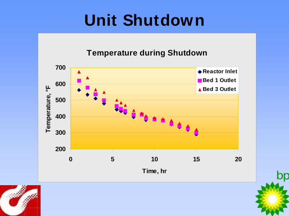
Unit Shutdown
Temperature during Shutdown
200
300
400
500
600
700
0 5 10 15 20
Time, hr
Tem
pera
ture
, °F
Reactor InletBed 1 OutletBed 3 Outlet

1717
Unit ShutdownViscosity during Shutdown
101214161820222426
0 5 10 15 20
Time, Hr
Visc
osity
, cSt
@ 1
22 °F Feed
Product
Start chemical injection
Injection complete

1818
ResultsSafety
• All catalyst was unloaded under air• Eliminated catalyst self-heating and pyrophorics
characteristics– Slight heating in bottom of bottom bed due to air
leaking• Eliminated dust emissions
Time savings• Faster shutdown procedure – no hot H2 strip• No delays for dust or pyrophorics• Permitting procedure was simplified• Unloaded catalyst faster than previous changeout
utilizing inert entry

1919
Results
Cost savings• Reduced time to shut down unit and unload
catalyst• No nitrogen required for inert entry operations
Intangibles• Reduced concern of entry operations by
technicians and refinery personnel• Improved quality and productivity

2020
Concerns
Reactor reached embrittlement temperature• May be due to faulty thermocouples
Unit was de-oiled at low pressure Catalyst had some “oily” areas• May be improved with better de-oiling procedure
Heating of catalyst in bottom bed• Likely due to valve not fully closed
Oil in reactor• Residual oil film removed by hydro blasting

2121
ConclusionsCATnapTM application was a successPassivation offers a viable alternative to inert entry operationsOffers possibility to largely eliminate what is commonly believed to be the most dangerous activity in petroleum refineriesCATnapTM technology is being evaluated for other BP operating units

2222

2323
Questions and Answers


