2009 DOE Hydrogen Program Development of Advanced Manufacturing Technologies for Low Cost Hydrogen Storage Vessels Carter Liu, PhD Quantum Fuel Systems Technologies Worldwide Inc. Brice A. Johnson The Boeing Company Date: May 20th 2009 Project ID # MF_06_Liu This presentation does not contain any proprietary, confidential, or otherwise restricted information
Transcript
2009 DOE Hydrogen ProgramDevelopment of Advanced Manufacturing
Technologies for Low Cost Hydrogen Storage Vessels
Carter Liu, PhD Quantum Fuel Systems Technologies Worldwide Inc.
Brice A. JohnsonThe Boeing Company
Date: May 20th 2009Project ID #MF_06_Liu
This presentation does not contain any proprietary, confidential, or otherwise restricted information
2
Overview
• Project start date 09/2008• Project end date: 09/2011• Percent complete: 9%
• Material system costs• Manufacturing processes
Timeline
Budget
Barriers
• Quantum Technologies, Inc. • The Boeing Company
(Boeing)• Pacific Northwest National
Laboratory (PNNL)• Lawrence Livermore National
Laboratory (LLNL)
Partners• Total Budget: $5,486,848
• DOE Share: $2,566,451
• QT/Boeing Share: $1,920,397
• FFRDC Share: $1,000,000
• FY08 Funding: $475,845
• Funding for FY09: $350,000
3
Project Objectives- Relevance
To manufacture Type IV H2 storage pressure vessels, utilizing a new hybrid process with the following features:
– Optimal elements of flexible fiber placement & commercial filament winding
– Reduced production cycle times by adaptations of high-speed “dry winding” methodology
With the aim of achieving:A manufacturing process with lower composite materialusage, cost & higher efficiency
4
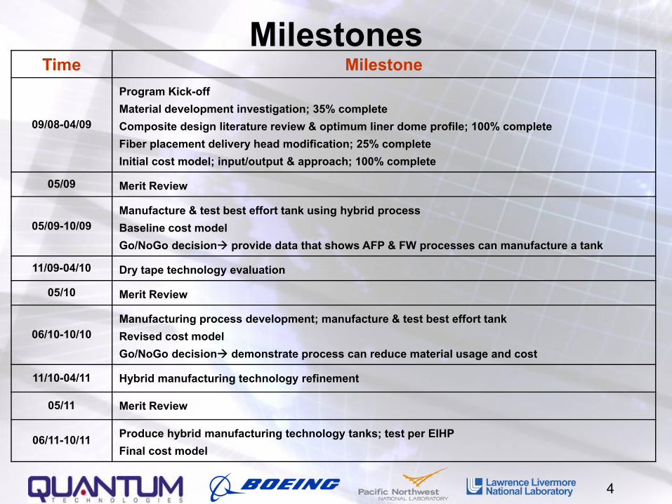
MilestonesTime Milestone
09/08-04/09
Program Kick-offMaterial development investigation; 35% completeComposite design literature review & optimum liner dome profile; 100% completeFiber placement delivery head modification; 25% complete Initial cost model; input/output & approach; 100% complete
05/09 Merit Review
05/09-10/09Manufacture & test best effort tank using hybrid processBaseline cost modelGo/NoGo decision provide data that shows AFP & FW processes can manufacture a tank
11/09-04/10 Dry tape technology evaluation
05/10 Merit Review
06/10-10/10Manufacturing process development; manufacture & test best effort tankRevised cost modelGo/NoGo decision demonstrate process can reduce material usage and cost
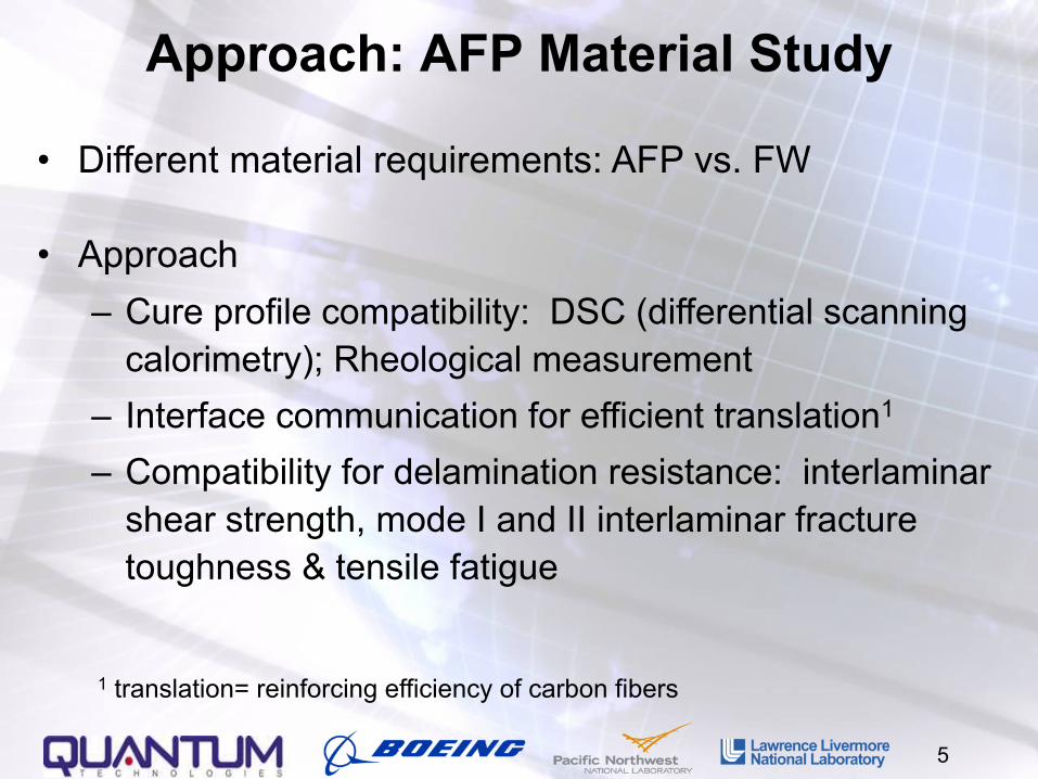
calorimetry); Rheological measurement– Interface communication for efficient translation1
– Compatibility for delamination resistance: interlaminar shear strength, mode I and II interlaminar fracture toughness & tensile fatigue
6
Accomplishment: Liner Dome Profile Investigation
• Reasons:
– The stress distribution along fiber tow path is strongly affected by the 2 principal radii of curvature
– Appropriate dome profile is desired for AFP process and filament winding process
– Weight, volume and cost efficiency
• Iso-tensoid dome is designed according to material properties and compared to measurements after molding
0
0.5
1
1.5
2
2.5
3
3.5
4
4.5
0.000 1.000 2.000 3.000 4.000 5.000 6.000 7.000
Polar Radius, inchAx
ial D
ista
nce,
inch
Optimum Dome Shape
FWD
AFD
• Deviations due to plastic shrinkage
• Improvement in dome design and molding process
7
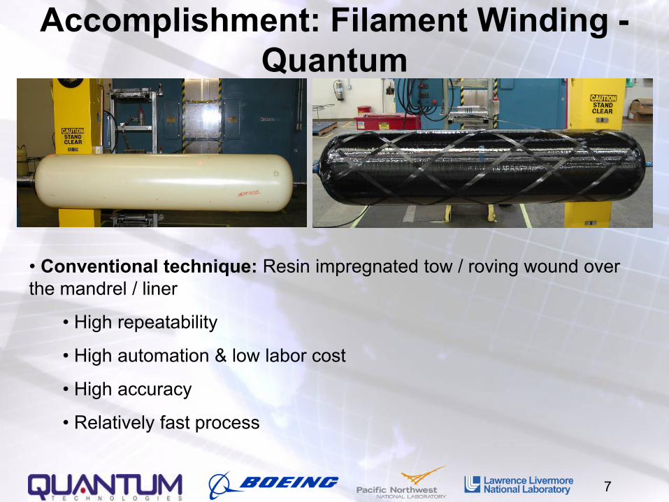
Accomplishment: Filament Winding -Quantum
• Conventional technique: Resin impregnated tow / roving wound over the mandrel / liner
• High repeatability
• High automation & low labor cost
• High accuracy
• Relatively fast process
8
Accomplishment: Filament Winding -Quantum
Quantum’s Analytical and FEA study:
• Optimal design = balance between low angle helicals (closer to boss edge, 0~10˚) for axial stress + high angle helicals (11~90˚) for radial stress
• The balance depends on the surface principal radii of curvature: Cylinder vs. Dome
Limitations on fiber path and orientation & continuous process nature many parasitic fibers are placed in the cylinder region in order to reinforce the dome
Fiber path = low angle + high angle helicals
9
Accomplishment: Fiber Placement is Scalable for High Pressure Storage Needs - Boeing
• Fiber placement, a CNC process adds or cuts multiple strips of composite material on demand.
– Allows maximum weight efficiency– Only places material where it is needed– Steering of fiber allows greater design
flexibility
• Existing machines don’t meet the DOE’s objectives
• Process is scalable to smaller parts
• Software available for smaller machines
10
Overall Concept- Boeing
• Use fiber placement for optimization:– Build up plies on the dome sections with minimal limitation on fiber
angle– Reinforcement of dome without adding weight to cylinder
• Develop method for integration between filament winding and fiber placement– Options include:
• In the same cell• In parallel cells• Off line fiber placement of reinforcement details
filament winding and fiber placement• Identified equipment and delivery head to be set up for
testing• Establishing lab capabilities to adapt fiber placement heads
to low cost automation systems• Integrating Boeing designed delivery heads onto these
systems• Preparing for initial layup tests on the dome structure
12
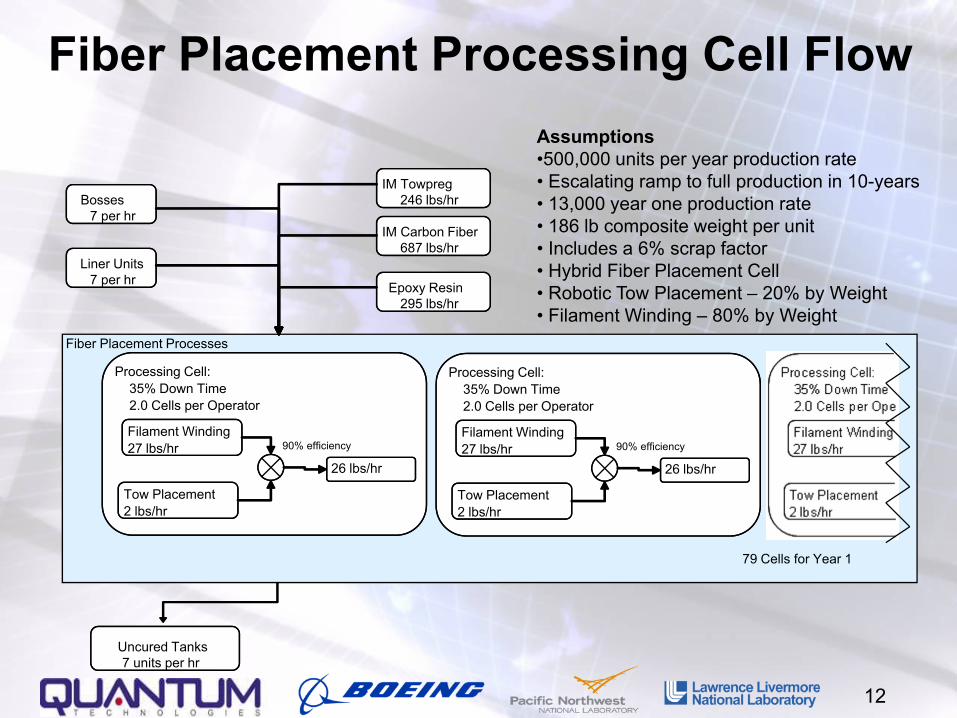
Fiber Placement Processing Cell Flow
Fiber Placement Processes
Processing Cell:35% Down Time2.0 Cells per Operator
Filament Winding27 lbs/hr
Tow Placement2 lbs/hr
26 lbs/hr
90% efficiency
79 Cells for Year 1
Liner Units7 per hr
IM Carbon Fiber687 lbs/hr
IM Towpreg246 lbs/hr
Epoxy Resin295 lbs/hr
Uncured Tanks7 units per hr
Bosses 7 per hr
Processing Cell:35% Down Time2.0 Cells per Operator
Filament Winding27 lbs/hr
Tow Placement2 lbs/hr
26 lbs/hr
90% efficiency
Assumptions•500,000 units per year production rate• Escalating ramp to full production in 10-years• 13,000 year one production rate• 186 lb composite weight per unit• Includes a 6% scrap factor• Hybrid Fiber Placement Cell• Robotic Tow Placement – 20% by Weight• Filament Winding – 80% by Weight
13
Future Work: Strategies for Program Goals
• Investigate fiber placement on dome structures using new, right sized, equipment
• Investigate material forms compatibility between filament winding and fiber placement
• Optimize tank structure taking advantage of fiber placement capabilities
• Hybridize with filament winding to leverage process productivity
• Fabricate delivery heads optimized for tank design and adapt to low cost automation platforms
14
Future Work: Head Design Issues• The fiber placement process usefulness increases the closer the head can reach
the center of the dome • Heads must be designed to minimize clearance with the boss• Programming focused on geodesic paths for minimal shear loading of composite
15
Cost Model Development- PNNL• Purpose: Assess the cost sensitivities of advanced processing methods for
manufacturing high pressure composite tanks.• Significant Composite Tank Manufacturing Costs
• Manufacturing time and cost factors: labor + equipment• Increased fiber translation = reduced composite weight• Material requirements for specific processes
– Raw Material Cost: Resins, carbon fiber types, ties to alternate fiber placement methods
– Related Hardware Cost: liner, fittings, bosses, etc– Labor rates: domestic or foreign
• Model Outputs = Alternate process tradeoffs for tank cost, weight, and manufacturing time
16
Cost Model Considerations• Independent Variables
– Production Rate [up to 500,000 units/year with 5% rejection rate]– Labor rate: domestic or foreign built– Winding and placement speeds– Raw Material Costs: resins, carbon fiber types, future fiber prices,
alternative materials, game changers?• Related hardware cost: liner, fittings, bosses, etc.• Alternate Processes
– Cost for weight benefit (material trades)– Cost of production– Return on investment– Trade on alternative processes– Threshold for profitability
• Material cost targets• Machine speed targets
• Risk Analysis • Market Analysis• Departure from existing baseline: choose an existing product and produce
deltas for our proposed product
17
Hydrogen Compatibility Studies- PNNLMotivation: Polymers are used as hydrogen permeation barriers in high pressure pipelines and vessels; hydrogen is well known to embrittle and blister metals. However, the effects on polymer materials is largely unknown. We are currently investigating these effects to determine the relevant parameters for degradation.
Stage 1: Amorphous polymers
• Variables: viscosity, depth, solubility, diffusion, pressure, temperature, decompression time; polystyrene is a model polymer that is extremely well characterized in the literature
• Preliminary results indicate that blistering does occur and is strongly dependent on viscosity/temperature
• Building thermal gradient stage to do combinatorial measurements of blistering with varying viscosity
Stage 2: Semi-crystalline polymers
• Majority of vessel/pipeline materials are semi-crystalline
• Build on results from amorphous polymers: amorphous vs. crystalline regions
• Variables now include degree of crystallinity & density
• Additionally, some specific materials selected by Quantum will be evaluated
Thermal Gradient Stage for In-situ Annealing in High-Pressure H2: Combinatorial Measurements
HotCold
HeaterCooling
Sample
80μm
T-Tg= 50 C T-Tg= 80 C
Blistering in Polystyrene (amorphous)• Preliminary measurements indicate strong viscosity dependence for micron sized blisters
– Size and density of blisters affected
• Thermal gradient allows continuous variation in viscosity (η) by varying temperature
• Allows combinatorial measurements
η
T-Tg
cold
hot
80μm
18
19
Future Work: Iterations between Composite Optimization & AFP process improvement
• The relationship between fiber tow quantity and angle distribution in the cylinder region to balance the axial and radial stresses
• Fiber tow path in the dome region to homogenize the stress along fiber length
• Interlaminar stress consideration near free-edges
• Non-linear stress distribution across the composite shell thickness
• Limitations from automatic fiber placement process
20
Future Work: Tape Fabrication Process Proof of Feasibility- LLNL
• Novel and unproven process, with many similarities to wet winding, fiber placement, and thermoplastic matrix composite fabrication processes
– File patent, pursue trade secret protection and licensing agreements
• Potential for process to be 100 times faster than conventional processes & economical even if 5 times faster
• Proof of Concept experiments are being executed • Learn enough about far-term process invented at LLNL to determine if it will be worthwhile for team members to adopt
21
Project Future Work• A best effort storage vessel will be manufactured using the hybrid process (combination of filament winding & fiber placement)
• Burst test and pressure cycle fatigue test will be performed on this tank
• Further iterations on composite design and AFP process improvements (manufacturing process development)
• Evaluate game-changing LLNL dry tape technology
• Cost model revisions to reflect latest manufacturing processes & large scale volume production
22
Project Summary
Relevance Investigate hydrogen storage manufacturing processes to approach the DOE cost targets and high-volume production targets
Approach AFP process material study; fiber needs to work in AFP & FWComposite design & optimizationAFP process improvementTest whether LLNL process is worthwhile to incorporate
Proposed Work Initial filament winding/fiber placement process to produce best effort tankLLNL process trialsPrepare cost model