2010 California Amendment to the 2010 California Amendment to the AASHTO L AASHTO LRFD RFD Bridge Design Bridge Design Specifications, Forth Edition Specifications, Forth Edition LRFD for the LRFD for the Design of Retaining Walls Design of Retaining Walls September 9, 2011 September 9, 2011 Presented by: Dr. Ted Liu Senior Transportation Engineer
Transcript
2010 California Amendment to the 2010 California Amendment to the AASHTO LAASHTO LRFD RFD Bridge Design Bridge Design
Specifications, Forth EditionSpecifications, Forth EditionLRFD for theLRFD for the Design of Retaining Walls Design of Retaining Walls
• CA Amendments to AASHTO LRFD Bridge Design Spec (Sep 2010)
• Caltrans Memo To Designers 1-35: Foundation Recommendation and ReportsFoundation Recommendation and Reports
• Caltrans Memo To Designers 3-1: Deep Foundations
• Caltrans Memo To Designers 4-1: Spread Footings
• Caltrans Memo To Designers 5-20: Foundation Report/Geotechnical Design Report Checklist for Earth Retaining Systems
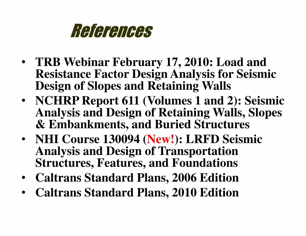
ReferencesReferences
• TRB Webinar February 17, 2010: Load and Resistance Factor Design Analysis for Seismic Design of Slopes and Retaining Walls
• NCHRP Report 611 (Volumes 1 and 2): Seismic Analysis and Design of Retaining Walls, Slopes & Embankments, and Buried StructuresAnalysis and Design of Retaining Walls, Slopes & Embankments, and Buried Structures
• NHI Course 130094 (New!): LRFD Seismic Analysis and Design of Transportation Structures, Features, and Foundations
• Caltrans Standard Plans, 2006 Edition
• Caltrans Standard Plans, 2010 Edition
Current Design in CaltransCurrent Design in Caltrans
• LRFD for bridge supports
• LRFD for Abutments, Earth retention systems and Buried structures effective October 4, 2010.
• For more information, please refer to website of “Office of Special Funded Projects, LRFD Information”http://www.dot.ca.gov/hq/esc/osfp/lrfd-information/lrfd-information.htm
RETAINING WALLS
MAY 2006 EDITION STANDARD PLANS 2010 EDITION STANDARD PLANS
Retaining Wall Type 1 - H = 4' through 30', Plan No. B3-1 Retaining Wall Type 1 - H = 4' through 30', Plan No. B3-1
Retaining Wall Type 1 - H = 32' through 36', Plan No. B3-2 Retaining Wall Type 1 - H = 32' through 36', Plan No. B3-2
Retaining Wall Type 1A, Plan No. B3-3 Retaining Wall Type 1A, Plan No. B3-3
Retaining Wall Type 2, Plan No. B3-4
Counterfort Retaining Wall Type 3, Plan No. B3-5
Counterfort Retaining Wall Type 4, Plan No. B3-6
Retaining Wall Type 5, Plan No. B3-7 Retaining Wall Type 5, Plan No. B3-4
Retaining Wall Details No. 1, Plan No. B3-8 Retaining Wall Details No. 1, Plan No. B3-5
Retaining Wall Details No. 2, Plan No. B3-9 Retaining Wall Details No. 2, Plan No. B3-6
Retaining Wall Type 6 - 6'-0" Maximum, Plan No. B3-11 Retaining Wall Type 6 Details No. 1 - 6'-0" Maximun, Plan No.
B3-7
Retaining Wall Type 6 Details No. 2 - 6'-0" Maximum, Plan No.
B3-8
Retaining Wall Type 1 - H = 4' through 30'
2006 Standard Plan
2010 Standard Plan
Retaining Wall Type 1A
2006 Standard Plan
2010 Standard Plan
Retaining Wall Type 5
2006 Standard Plan
2010 Standard Plan
Retaining Wall Type 6A - 6'-0" Maximum
2006 Standard Plan
2010 Standard Plan
Retaining Wall Type 6B - 6'-0" Maximum
2006 Standard Plan
2010 Standard Plan
TRB Webinar on February 17, 2010
NCHRP 12-70 Project
Need for NCHRP 12-70 Project“TRB Webinar February 17, 2010: Load and Resistance Factor Design
Analysis for Seismic Design of Slopes and Retaining Walls”
Difficulties with retaining wall seismic design
� M-O method “blows up” with high back slopes, high
Capacity/Demand Ratio.“TRB Webinar February 17, 2010: Load and Resistance Factor Design Analysis
for Seismic Design of Slopes and Retaining Walls”
LRFD versus ASD
• The following condition must be
satisfied
Load Effects ≤Resistance
• Difference in LRFD and ASD methods is • Difference in LRFD and ASD methods is
based on how uncertainties in loads
and resistances are accounted for
• LRFD: Load and resistance factors will
be refined with time
Load Combinations and Load Factors“TRB Webinar February 17, 2010: Load and Resistance Factor Design Analysis
for Seismic Design of Slopes and Retaining Walls”
Limit States for Earthquake Design“TRB Webinar February 17, 2010: Load and Resistance Factor Design Analysis
for Seismic Design of Slopes and Retaining Walls”
Load Factors for Seismic Design“TRB Webinar February 17, 2010: Load and Resistance Factor Design Analysis
for Seismic Design of Slopes and Retaining Walls”
Resistance Factors“TRB Webinar February 17, 2010: Load and Resistance Factor Design Analysis
for Seismic Design of Slopes and Retaining Walls”
Limit states for LRFDLimit states for LRFD
• Service Limit State:
Load combinations (LCs) to ensure structure performance for service life
• Strength Limit State:
LCs to ensure structural integrity despite LCs to ensure structural integrity despite distress and damage
• Extreme Event Limit State:
LCs to ensure structural survival during extreme events (EQ, VC)
• Fatigue and Fracture Limit State:
Not an issue in foundation design
How LRFD applied to Foundation DesignHow LRFD applied to Foundation Design
• Service Limit State (Permanent & total load):pile settlement, pile top deflection (φ=1.0)
• Strength Limit State (Comp & Tension):• Strength Limit State (Comp & Tension):Determine pile length w/ load from SLS (φ=0.7)φ=0.5 for CIDH tip resistance
φ=1.0 for uplift group (only for block analysis) in cohesionless material
• Extreme Event Limit State (Comp & Tension):Determine pile length w/ load from EELS (φ=1.0)
Information from Structure DesignerInformation from Structure Designer
• Foundation type (CIDH, Concrete pile, Steel pile)
• Scour Data
• Finished Grade Elevation
• Cut-off Elevation
• Pile Cap size
• Permissible Settlement under Service Load
• Number of Pile per Support
• At the early stage of design (PFR)
Preliminary Foundation Design Data Sheet
SupportFoundation Type(s)
Considered
Estimate of Maximum Factored
Compression Loads (kips)
Abut 1 Class 140 140 per pileAbut 1 Class 140 140 per pile
Bent 2Class 200 Pile Group
60 inch CIDH Pile Shaft
280 per pile
1850 per column
Bent 330 inch CIDH Pile Group
60 inch CIDH Pile Shaft1950 per column
Abut 4 24 inch CIDH Pile Group 170 per pile
• At the foundation design stage (FR)
Support
No.
Design
Metho
d
Pile Type
Finish
Grade
Elevatio
n (ft)
Cut-off
Elevatio
n
(ft)
Pile Cap Size (ft)
Permissible
Movement under
Service Load (in)Number
of Piles
per
Support
B L DV DH
Abut 1 LRFD 1” 0.25”
Bent 2 LRFD 1” 0.25”
Abut 3 LRFD 1” 0.25”
Extreme Event Limit State
Support No.
Total Vertical Load per Support (kip)
Lateral Load at Abutments (kip)
Total Load Permanent Load**
Abut 1
Bent 2
Abut 3
Support
No.
Strength Limit State (Controlling Group)Extreme Event Limit State
(Controlling Group)
Compression Tension Compression Tension
Per
Support
Max.
Per Pile
Per
Support
Max.
Per Pile
Per
Support
Max.
Per Pile
Per
Support
Max.
Per Pile
Abut 1
Bent 2
Abut 3
Support No.Degradation Scour
(ft)
Base Flood Scour (ft)
Total Scour
(ft)
Contraction Local
Abut 1
Bent 2
Abut 3
• Foundation Recommendation for Bents
(MTD 3-1 Attachment 1)
• Bent Pile Group
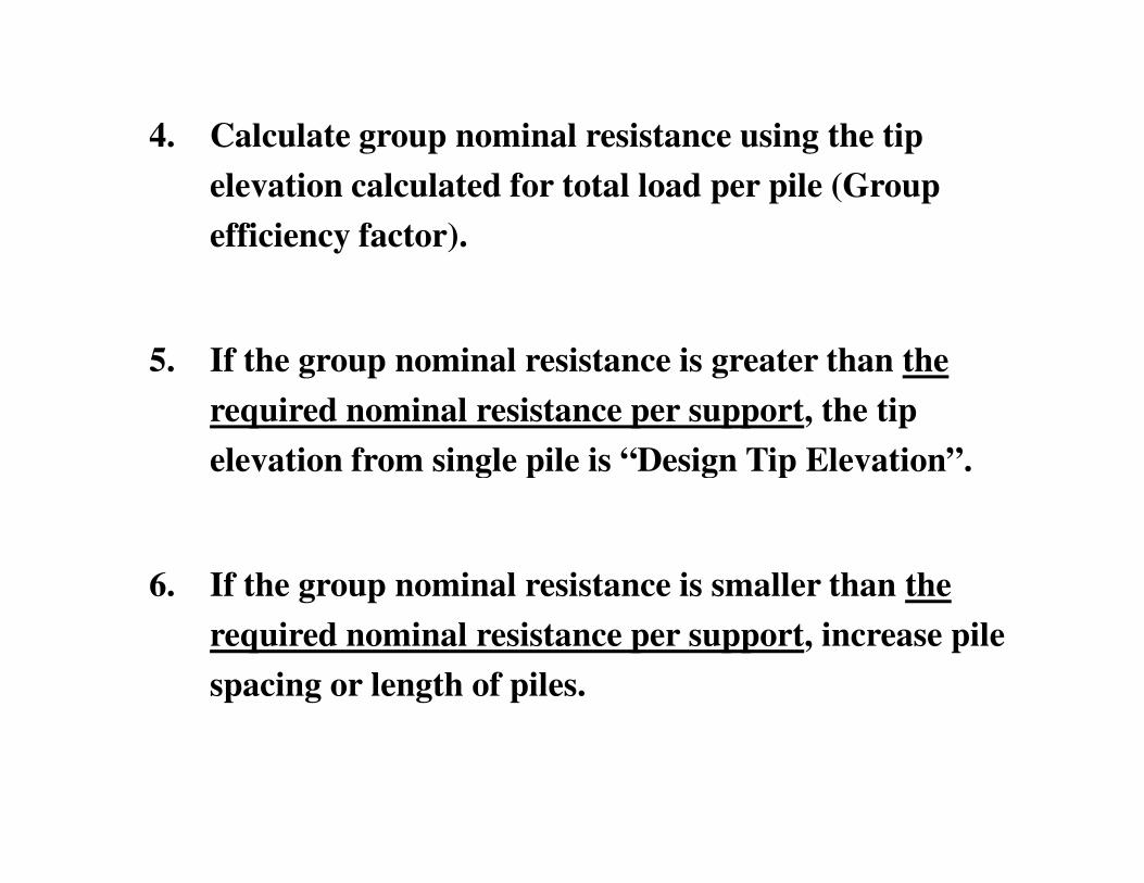
1. Calculate “Required Nominal Resistance” for
compression per pile (φ=0.7).
2. Calculate tip elevation for “Required Nominal 2. Calculate tip elevation for “Required Nominal
Resistance” for single pile.
3. Calculate “Required Nominal Resistance” for total
load per Support (φ=0.7=0.7=0.7=0.7).
4. Calculate group nominal resistance using the tip
elevation calculated for total load per pile (Group
efficiency factor).
5. If the group nominal resistance is greater than the
required nominal resistance per support, the tip
elevation from single pile is “Design Tip Elevation”.elevation from single pile is “Design Tip Elevation”.
6. If the group nominal resistance is smaller than the
required nominal resistance per support, increase pile
spacing or length of piles.
• Pile Data Table for Design Example
390420
• Group Pile in LRFD Spec
1. Minimum pile spacing
- For driven pile, 36 inch or 2.0 pile diameters (CA
Amendment 10.7.1.2)
- For CIDH pile, 2.5 pile diameters (CA Amendments
10.8.1.2): sequence of CIDH pile installation required
in the contract documents (less than 3.0 pile dia).
• Group Pile in LRFD Spec
2. CIDH and Driven pile group capacity in cohesive soil
- For compression, lesser of 1) Σ Nominal axial Nominal axial Nominal axial Nominal axial
resistance of each pile 2) Nominal axial resistance of resistance of each pile 2) Nominal axial resistance of resistance of each pile 2) Nominal axial resistance of resistance of each pile 2) Nominal axial resistance of
- For uplift, lesser of 1) Σ Nominal uplift resistance of Nominal uplift resistance of Nominal uplift resistance of Nominal uplift resistance of
each pile 2) Nominal uplift resistance of pile group each pile 2) Nominal uplift resistance of pile group each pile 2) Nominal uplift resistance of pile group each pile 2) Nominal uplift resistance of pile group
considered as a blockconsidered as a blockconsidered as a blockconsidered as a block
• Group Pile in LRFD Spec
3. CIDH pile and Driven pile group in cohesionless soil
- For compression, 1) group efficiency factor for CIDH
pile, 2) Σ Nominal axial resistance of each pile for
Driven pileDriven pile
- For uplift, lesser of 1) Σ Nominal uplift resistance of Nominal uplift resistance of Nominal uplift resistance of Nominal uplift resistance of
each pile 2) Nominal uplift resistance of pile group each pile 2) Nominal uplift resistance of pile group each pile 2) Nominal uplift resistance of pile group each pile 2) Nominal uplift resistance of pile group
considered as a block (resistance factor=1.0 even for considered as a block (resistance factor=1.0 even for considered as a block (resistance factor=1.0 even for considered as a block (resistance factor=1.0 even for