25
2011 AFRC Industrial Flares Colloquium Houston, TX September 18-21, 2011 T F T om Farmer Zeeco Flare Applications Engineer 2011 ZEECO, INC. 2010 ZEECO, INC. 2011 ZEECO, INC.

2011 AFRC Industrial Flares ColloquiumHouston, TX September 18-21, 2011
T FTom FarmerZeeco Flare Applications Engineer
2011 ZEECO, INC. 2010 ZEECO, INC. 2011 ZEECO, INC.

Company Profile Incorporated in 1979 250-acre facility located in Broken Arrow, OK Specialists in the design and manufacturing of combustion equipment
2011 ZEECO, INC.

Zeeco Product Lines
Flare Systems Incineration SystemsIndustrial Burners
2011 ZEECO, INC.
Flare Systems Incineration SystemsIndustrial Burners
BackgroundFl t ti d t d b TCEQ d Th U i it f T Flare testing conducted by TCEQ and The University of Texas
Determined how air assisted and steam assisted flares perform at turndown rates
Suggested that incorrectly designed or operated flares may gg y g p yreduce the Destruction and Removal Efficiency (DRE) of flares
Zeeco testing Zeeco testing
Performed testing of steam assisted flares to compliment TCEQ t ttests
Zeeco focused on API recommended purge rates
2011 ZEECO, INC.

Testing Instrumentation & Setup Performed at Zeeco Combustion Research & Test Facility in Broken
Arrow, OK
Equipment 36” Steam Assisted Flare Tip QFSC Steam Assisted Tip UFSC Steam Assisted Flare Tip
Temperature elements Temperature elements positioned on flare tip
2011 ZEECO, INC.
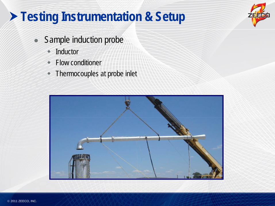
Testing Instrumentation & Setup Sample induction probe Inductor Flow conditioner Thermocouples at probe inlet
2011 ZEECO, INC.

Testing Instrumentation & Setup LSI FLIR GasFindIR camera Air Hygiene emissions testing service Miscellaneous equipment Video camera Still camera Still camera
2011 ZEECO, INC.

Testing
Phase 1- Test API recommended purge rates with steam operating at cooling ratesp g g Three purge rates tested Velocity Seal purge rates
G S Gas Seal purge rates No Seal purge rates
Velocity Seal Gas Seal No Seal
Purge Gas NG NG NG
Purge Rate (SCFH)
990 250 1992(SCFH)
2011 ZEECO, INC.

Testing Three steam assist methods were tested for each purge rate Center steam only Upper steam only Upper steam only Combined upper and
center steam
2011 ZEECO, INC.

Testing
Phase 2- Building a Hypothesis Set steam rates and adjusted gas flow to achieve a high j g g
destruction efficiency Set purge rates and adjusted center, upper, and combined
t fl t t hi hi h d t ti ffi i steam flow rates to achieve a high destruction efficiency The steam flow was turned down as low as reasonably possible without
condensing
A trend developed between the DRE and the LHV of the combined steam and gas streamcombined steam and gas stream
2011 ZEECO, INC.

Testing Phase 3- Verify
Hypothesis Test points selected to
produce a combined stream LHV which stream LHV, which achieved a 98% destruction efficiency
2011 ZEECO, INC.
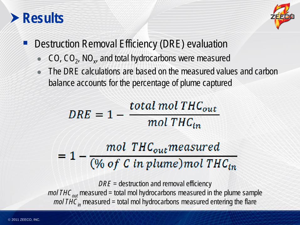
Results Destruction Removal Efficiency (DRE) evaluation
CO, CO2, NOx, and total hydrocarbons were measured The DRE calculations are based on the measured values and carbon
balance accounts for the percentage of plume captured
DRE = destruction and removal efficiencymol THC measured = total mol hydrocarbons measured in the plume sample
2011 ZEECO, INC.
mol THCout measured = total mol hydrocarbons measured in the plume samplemol THCin measured = total mol hydrocarbons measured entering the flare

Results Summary
Testing indicated that the DRE is impaired by cooling steam while operating at API recommended purge rates
Strong correlation between the DRE and the LHV of the combined gas and steam ratesgas and steam rates
The addition of center steam resulted in the largest reduction of DRE
2011 ZEECO, INC.

Results Combined LHV vs. DRE with Center Steam Only
LHV vs. DRE with Center Steam Only
95
100
LHV vs. DRE with Center Steam Only
80
85
90
uctio
n Effi
cienc
y
70
75
Dest
ru
650 50 100 150 200 250 300 350 400 450
LHV
2011 ZEECO, INC.

Results Combined LHV vs. DRE with Upper Steam Only
LHV vs. DRE with Upper Steam Only
95
100
LHV vs. DRE with Upper Steam Only
80
85
90
uctio
n Effi
cienc
y
70
75
Dest
ru
650 50 100 150 200 250 300 350 400 450
LHV
2011 ZEECO, INC.

Results Combined LHV vs. DRE with Upper & Center Steam
LHV vs. DRE Combination Only
95
100
LHV vs. DRE Combination Only
80
85
90
ruct
ion E
fficie
ncy
70
75
Dest
r
650 50 100 150 200 250 300 350 400
LHV
2011 ZEECO, INC.

Results Steam to Gas Ratio vs. DRE with Upper & Center Steam
Upper & Center Steam
92949698
100
Upper & Center Steam
828486889092
uctio
n Effi
cienc
y %
727476788082
Dest
ru
7072
0 1 2 3 4 5 6 7 8 9 10
Steam to Flare Gas Ratio (lb/lb)
2011 ZEECO, INC.

Results Steam to Gas Ratio vs. DRE with Center Steam
Center Steam
92949698
100
Center Steam
828486889092
uctio
n Effi
cienc
y %
727476788082
Dest
ru
7072
0 1 2 3 4 5 6 7 8 9 10
Steam to Flare Gas Ratio (lb/lb)
2011 ZEECO, INC.

Results Steam to Gas Ratio vs. DRE with Upper Steam
9899
100
899091929394959697
818283848586878889
RUCT
ION
EFFE
CIEN
CY %
727374757677787980
DEST
R
676869707172
0 1 2 3 4 5 6 7STEAM TO FLARE GAS RATIO (LB/LB)
Z T i i h N l G CMA T i i h
2011 ZEECO, INC.
Zeeco Testing with Natural Gas (914 TU/SCF)
CMA Testing withPropylene (2183 BTU/SCF)

Results Thermocouple evaluation
Center Steam is used as an effective means for cooling the flare tip
800
Flare Tip Temperature 7/18/11 Afternoon
Center
500
600
700
deg
. F
Upper & Center Steam
Center Steam Only
200
300
400
Tem
pera
ture
Level 1Level 2Level 3
U
0
100
0:14:24 0:43:12 1:12:00 1:40:48 2:09:36 2:38:24 3:07:12 3:36:00 4:04:48 4:33:36 5:02:24
Upper Steam Only
2011 ZEECO, INC.
Time

Results Thermocouple evaluation continued
At low center steam rates, burning was found within the flare tip
Flare Tip Temperature 7/19/11 Afternoon
600
700
800
900
eg. F
p p
200
300
400
500
Tem
pera
ture
de
Level 1Level 2Level 3
0
100
200
0:00:00 1:12:00 2:24:00 3:36:00 4:48:00 6:00:00
Time
2011 ZEECO, INC.

Results Thermocouple evaluation continued
When the flame was stable and located at the exit of the flare tip, a higher DRE was observed
Flare Tip Temperature 7/22/11 Morning
500
600
700
g. F
p p g
200
300
400
Tem
pera
ture
deg
Level 1Level 2Level 3
0
100
7:12:00 AM 8:24:00 AM 9:36:00 AM 10:48:00 AM 12:00:00 PM
Ti
2011 ZEECO, INC.
Time

Conclusion Constant cooling steam is necessary for thermal protection of
the flare tips and equipment
Strong indication that cooling steam, while operating at API Purge Rates does reduce destruction efficiencyPurge Rates, does reduce destruction efficiency
LHV for combined steam and gas i f di ti th is necessary for predicting the destruction efficiency of flares
2011 ZEECO, INC.

Recommendations Is this a real problem?
Many plants operate with sweep gases that are higher than API recommended rates
API rates are listed as the minimum recommended purge rate
Increase LHV combustion zone A minimum of 225 Btu/SCF is recommended
Use nitrogen purge where available
Use other means of flashback protection Flame arrestor Liquid seal base of flare stack and designed for flashback
2011 ZEECO, INC.
Liquid seal base of flare stack and designed for flashback

Questions
2010 ZEECO, INC. 2011 ZEECO, INC.


