ABSTRACTFor the past five years an extensive array of research has beenconducted to evaluate the use of composite materials for repairingonshore and offshore pipelines. Much of this research has been co-sponsored by the composite manufacturers and operators via the
Pipeline Research Council International, Inc. (PRCI). Althoughcomposite systems are a generally-accepted method for repairingcorroded and mechanically-damaged onshore pipelines, limited work
has been performed in evaluating the use of this technology in offshoreapplications. The paper provides an overview of efforts performed todate, including a previous joint industry effort involving the MineralsManagement Service (now BOEMRE), the Offshore Technology
Research Center at Texas A&M University, Stress EngineeringServices, Inc., and several composite repair manufacturers.
Also included in this paper is information on an upcoming program
involving PRCI and composite manufacturers where test samples will be subjected to operating conditions in a saltwater environment for10,000 hours. This program will contribute significantly to the future ofoffshore riser repairs and foster future applications and investigations
involving operators by integrating their insights regarding the need for
composite repair based on emerging technology.
INTRODUCTIONRisers are critical components in offshore operations as they extend thewellhead at the mudline to the surface as shown in Figure 1. During
operation risers are subject to degradation mechanisms includingexternal corrosion and mechanical damage due to contact with outsideforces. To permit risers to operate safely it is sometimes necessary to
perform repairs. Conventional repair techniques incorporate externalsteel clamps that are either welded or bolted to the outside surface ofthe riser. Challenges exist with installing steel clamps that includeissues such as mobilizing the heavy clamp, welding to an operating
riser pipe (including safety issues), and installation expenses. For thesereasons, alternative solutions such as composite repair sleeves provide
an attractive option as they are relatively inexpensive, lightweight, donot require welding, and are relatively simple to install.
What separates this research effort from prior studies is that theevaluation of composite repair technology for offshore applicationsalso includes the development of a design methodology based on limitanalysis methods and strain-based design techniques. The actual design
coupled with prototype testing is also a unique feature of this researcheffort.
The sections that follow provide the background, approach, and results
of this research program. The Background section documents lessonslearned from previous research efforts. Composite Material
Performance includes a brief discussion on material performance as it
relates to the repair of risers. The discussion in Strain-based DesignMethods details how a methodology was developed to evaluate the
performance of the repair by determining how strain was reduced in thedamaged section of the riser based on the application of certain loading
conditions.
The Development of Riser Composite Repair System section is the core
of this study as it details the analytical methods that were used todesign the carbon half-shell system fabricated and tested for this studyThe Development of a Composite Repair System and Evaluating theOptimized Repair System sections details how analysis and full-scale
testing were used to validate the quality of design and if the systemachieved its intended reinforcement levels based on the prior designwork. The Conclusions section captures the critical insights gainedduring the study to assist industry in evaluating this emerging
technology.
BACKGROUNDThere is a significant body of work that has been conducted to assess
the use of composite materials for offshore applications. Most of thiswork has been focused on assessing the performance of composite andcomposite-reinforced riser systems. Some work on composite choke
and kill lines has also been done. Additionally, a multitude of researchand applications publications exist in the area of using compositematerials to reinforce onshore pipelines. Independent studies have also
been performed to assess various aspects of composite systemincluding long-term performance. A final area of interest includes priostudies that contributed to the development of reinforcing steel using
composite materials. These include investigations on limit analysis andstrain-based design methods.In performing the literature review for this research program, thereviewed documents were grouped into five different categories based
on their subject matter. These categories are listed below andcorrespond to the five subject matters contained within this section.
1. Reasons for repairing pipelines2. Using composite materials for offshore applications
3. Repairing onshore pipelines using composite materials4. Assessing the performance of composite materials5. Strain-based design methods and limit state design.
Reasons for Repairing Pipelines and RisersBefore discussing the specific methods in which pipelines and risers arerepaired using composite materials, it is necessary to discuss why andunder what conditions repairs are required. Pipelines and risersexperience damage and deterioration including corrosion, externa
damage in the form of dents caused by impact, and excessive loadsgenerated by extreme conditions such as those associated with
8/13/2019 2011 Oct - Alexander, C., Et Al - IOPF2011-7002-Houston
hurricanes. Corrosion is a metallurgical phenomenon that reduces thewall thickness of carbon steel. The corroded wall reduces the
mechanical integrity of the riser pipe and under extreme conditionsfailure can result in the form of either leaks or ruptures. Most pipelinedesign and operating codes, such as ASME B31.4, LiquidTransportation Systems for Hydrocarbons, Liquid Petroleum Gas,
Anhydrous Ammonia, and Alcohols [1] and ASME B31.8, Gas
Transmission and Distribution Piping System [2] have procedures forassessing the severity of corrosion. The procedures in these codes are based primarily on ASME B31G, Method for Determining the
Remaining Strength of Corroded Pipelines [3].
The variables involved in assessing corroded pipelines include:
• Corrosion depth as a percentage of the uncorroded wall thickness
• Maximum allowable longitudinal extend of the corroded area
• Safe maximum operating pressure for the corroded area.
Basically, the evaluation process involves quantifying the corrosiondepth and length and then calculating the safe maximum operating
pressure for the given pipe grade. If the desired operating pressurecannot be achieved, the pipeline operator must chose to re-rate the
pipeline to a lower pressure, remove the corroded section with a
replacement spool, or make a repair.
In addition to corrosion, pipelines and risers can be damaged by impactwith external forces. The resulting damage typically manifests itself inthe form of dents, gouges, or combinations of both known asmechanical damage. When these defects are identified, an assessment
process is required to determine if their severity reduces the mechanicalintegrity of the pipeline. As with assessments associated withcorrosion, if the damage is severe enough operators must chose to re-
rate through pressure reduction, remove and replace the damagedsection, or make a repair.
Use of Composite Materials in Offshore ApplicationsIn a review of the open literature, it is possible to obtain technical
publications representing viable research dating back 20 years in whichcomposite materials were used as construction materials for offshore
structures and components is discussed. The most prevalent topic ofdiscussion concerns high-performance composite tubes for riser
production. The Institut Francais du Petrole (IFP) started work in thelate 1970s assessing the use of composite materials in various
applications for the offshore oil industry in water depths up to 1,000meters. Their efforts, relative to assessments for riser designs, involvedfull-scale testing on composite tubes subjected to pressure, tension,
bending, fatigue, aging, corrosion, and abrasion. The test matrix
involved more than 60 samples and included carbon fiber samples,glass fiber samples, and hybrid composite samples involving bothcarbon and glass fibers [4 and 5]. The conclusions from these effortsdemonstrated that it is possible to fabricate high performance
composite tubes for offshore riser applications. One closing comment
from this reference was that defect tolerance of the tubes was notquantified and that additional studies should be conducted to assess thecapabilities of non-destructive examination (NDE) techniques in
quantifying imperfections should they exist.
In a follow-up effort, IFP published another paper at the Offshore
Technology Conference (OTC) fours years following the initial 1988 paper. The topic of this paper addressed defect tolerance andnondestructive testing [6]. The program objectives associated with theIFP study included the following:
• Assessment of the influence of defects on the ultimate performance of composite tubes
• Impact study
• Fatigue tension testing of tubes with deliberate built-in or applieddefects
• Assessment of NDE methods for detecting the presence andevolution of deliberate defects
• Evaluation of acoustic emission for assessing the ultimate
performance of used tubes (especially those subjected to fatiguedamage)
In the late 1990s, an extensive research program included Lincoln
Composites, Shell Oil Company, Conoco, Hydril, University oHouston, Hexcel Corporation, and Stress Engineering Services, Inc
that was undertaken to assess the capabilities of composite productionrisers for deep water depths up to 5,000 feet (cf. references [7] through[11]). In a program similar to the one conducted by IFP, this programincorporated a total of 80 test samples that were fabricated and tested
This program also included stress-rupture testing and generated datathat were used to establish confidence in the long-term behavior ocomposite materials under sustained load [11]. The conclusion fromthese studies was that the prototype composite product riser met the
cost, weight, and performance goals of the research program.
Repairing Onshore Pipelines Using Composite Materials
For more than a decade composite repair systems have been used torepair damaged pipelines. The majority of this remediation work has
involved the repair of onshore pipelines subject to corrosion that hasinvolved restoration of circumferential or hoop strength due to locawall loss of the steel. A review of the open literature demonstrates thaaddressing this stress state has been the primary focus of research
efforts up to this point in time. Because approved composite materialshave been accepted as a viable repair options in both the ASME B31.4and B31.8 pipeline codes, it should be noted that composite materials
are primarily used to re-rate corroded pipelines. In other words, if therepair or cut-out options were not invoked by the operator, the onlyother option would be for the operating pressure to be reduced
Conversely, if the composite material option is used, the operating pressure will be partially or fully restored. Additionally, mechanicadamage (e.g. dents with gouges) has been repaired in situ usingcomposite materials and validated experimentally using both burst and
cyclic pressure fatigue testing.
Readers interested in learning more about the history of onshore pipeline repairs using composite materials are encouraged to read the
paper by Alexander and Francini presented at the 2006 InternationaPipeline Conference in Calgary [12].
COMPOSITE MATERIAL PERFORMANCEAs with any new application of existing or emerging technologyresources are available for assessing predicted behaviors. Previous
background information has been cited on studies and research
associated with the application of composite materials in offshore
applications. This work focused on assessing the use of compositematerials in fabricating fully-composite or hybrid designs using a steeliner with a composite overwrap. Provided in this section are reviews o
research not specifically aimed at offshore applications, but arecontributory in nature to assessing the use of composite materials inreinforcing offshore risers. Subjects considered in this section include
residual stresses, damage mechanisms, as well as discussions onenvironmental effects and long-term performance.
Residual Stresses
The open literature has only sparse data and guidance for industry onthe subject of “residual” stresses generated in composite materialduring manufacturing. Hyer addressed environmentally induced
8/13/2019 2011 Oct - Alexander, C., Et Al - IOPF2011-7002-Houston
stresses in laminates, with specific discussions on residual thermalstresses generated during curing of the resin in the composite [13].
Recognizing that during curing it is not unreasonable to experienceexothermic reaction temperatures of epoxy resins on the order of220°F, a resulting temperature differential on the order of 150°F resultswhen cooling down to ambient conditions. As a result, depending on
the composite architecture and coefficients of thermal expansion,
compressive stresses on the order of 5,000 to 6,000 psi are possible.While this topic is noted as important, due to the overall complexity ofthis subject, it is likely that experimental efforts are best-suited to
quantitatively determine if a problem actually exists.
Damage MechanismsAs part of the design process, it is important to identify the potential
failure mechanisms for the riser composite repair system. The effects offatigue, impact, and environmental effects are considered in thisdiscussion.
FatigueIn addition to considering static loads, it is important to consider the
effect that cyclic loads have on the performance of a composite repairsystem. It is possible for composites that are subjected to cyclic loads to
fail at stresses significantly less than the ultimate strength of therespective materials. Unidirectional continuous-fiber-reinforced
composite are known to possess fatigue resistance in the fiber direction, because the load is primarily carried by the fibers that generally exhibitresistance to fatigue [14]. This observation is important in terms ofselecting materials for the composite repair system. Numerous studies
have been performed that addresses damage initiation and propagationduring fatigue of composite laminates [15 – 17]. Damage first initiates
by separation of the fibers from the matrix (i.e. debonding) in the fiber-rich regions of the plies in which the fibers lie perpendicular to the
principal direction of loading. Elevated stress concentrations at thefiber-matrix interface initiate these cracks. After initiation the cracktypically propagates along the interface between the fibers and thematrix and can extend over the entire width of the ply. The compositeundergoes final fracture when its overall strength is weakened by the
presence of longitudinal-ply cracks and delamination cracks. From a performance standpoint, in the presence of fatigue mechanisms, there is
a gradual decrease in the static strength (and modulus of elasticity) ofthe composite material as it is subjected to an increasing number ofcycles at a given stress level.
ImpactIn the design of composite repair system for offshore risers, the role ofimpact resistance is critical. Factors such as wave motion and contactwith other structures such as ships and other risers are examples of
impact. The metric for assessing the ability of a composite to withstanddamage after impact is energy absorption, often measured in ft-lbs/in
2.
Based on results from Broutman and Mallick [18], E-glass-epoxylaminates exhibit the highest energy absorption level per unit area (222
ft-lbs/in2), whereas graphite fiber epoxy laminates (GY-70) exhibitedthe lowest energy absorption capacities (5.85 ft-lbs/in2) of the materialsconsidered in their study. In terms of the present study, it is importantthat, as a minimum, E-glass materials be used as an outer wrap of the
repair to provide protection when carbon materials are used as the primary reinforcing material in the system.
Environmental EffectsOne of the concerns in using carbon fiber materials to repair steel
pipeline relates to the potential for developing corrosion at the
interface. Experimental results show that when carbon fiber/epoxy resincomposite materials are joined with high-strength titanium alloys,aluminum alloys, stainless steel (i.e. l% Cr l8% Ni 9% Ti), or otherstructural materials, galvanic corrosion and crevice corrosion take place
at the interface boundaries. This corrosion is primarily determined bythe electrochemical properties of the materials. It is also related to the
materials' mutual coupling situation, treatment technology, andenvironmental conditions. Galvanic corrosion is affected by thecoupled materials' static energy of corrosion, galvanic currents, andother dynamic closed-circuit properties [19]. Because of the potentia
for developing corrosion at the interface, a boundary must be
established between the carbon materials and the steel pipe. The use oE-glass with an epoxy matrix is a viable option to prevent contact between the carbon and steel materials.
Long-term Performance CharacteristicsOne of the general concerns across industry regarding the use ocomposite materials is their long-term performance and the potential
for degradation in strength. In the absence of long-term data, designsusing composite materials have been the use of large safety factorsOne of the more significant bodies of research conducted to date on the
long-term performance of composite materials was performed for theState of California Department of Transportation (CALTRANS) bySteckel and Hawkins of the Space Materials Laboratory in assessing
the use of composite materials for infrastructure applications such ashighways bridge columns [20]. This ninety plus page documen
provides extensive data on the long-term performance of selectedcomposite systems including carbon-epoxy and E-glass/epoxy. The
effects of environmental exposure on the mechanical and physica properties of these select systems are summarized in Figure 2 andTable 1. The plus/minus values shown in this table correspond to thestandard deviations.
In addition to the CALTRANS research, another important documenwas referenced in order to determine an acceptable design stress for thecomposite fiber materials. ASME commissioned the Hydrogen Projec
Team and Becht Engineering Co., Inc. to develop guidelines for designfactors in fabricating high-pressure composite hydrogen tanks. Theresult of the effort produced ASME STP/PT-005, Design FactoGuidelines for High-Pressure Composite Hydrogen Tanks [21]. Thisreport provides recommended design factors relative to short-term burs
pressure and interim margins for long-term stress rupture based on afixed 15-year design life for fully wrapped and hoop wrapped
composite tanks with metal liners. Part of this effort included a reviewof the design margins between burst and the maximum allowableworking pressures for tanks fabricated using composite materials. Themajority of international design codes have a design margin of 2 for
hoop wrapped tanks, and an average value on the order of 2.5 for fullywrapped tanks [21]. Additionally, design guidelines are providedrelative to the stress limit as reflected in the following text from thisdocument.
The rules should permit specification of a required design life However, to do so requires development of a design methodologythat considers stress rupture for composite tanks. Until such adesign methodology is developed, it is recommended that the fixed
15-year life and a 0.4 stress ratio for hoop wrapped tanks be used(STP/PTY-005, page 11).
Along the same lines, ASTM D2992 for fiberglass pipe and fittings
designates that the design be based on one-half (i.e. 0.5) the minimumexpected fiber stress to rupture in 100,000 hours (95% confidencelevel), or the 50-year strength, whichever is less [22].
DEVELOPMENT OF A COMPOSITE REPAIR SYSTEMThe principal aim of this study was to design a composite system torepair offshore risers incorporating design requirements, materiaselection, and installation techniques. This also includes identifying andtechnically addressing the variables required to develop the composite
8/13/2019 2011 Oct - Alexander, C., Et Al - IOPF2011-7002-Houston
repair system. The design requirements for this effort was to develop acomposite system that repairs corroded or damaged risers and ensures
that the global load path stresses in the steel portion of the riser remain below an acceptable level. This must include combined pressure,tension, and bending loads.
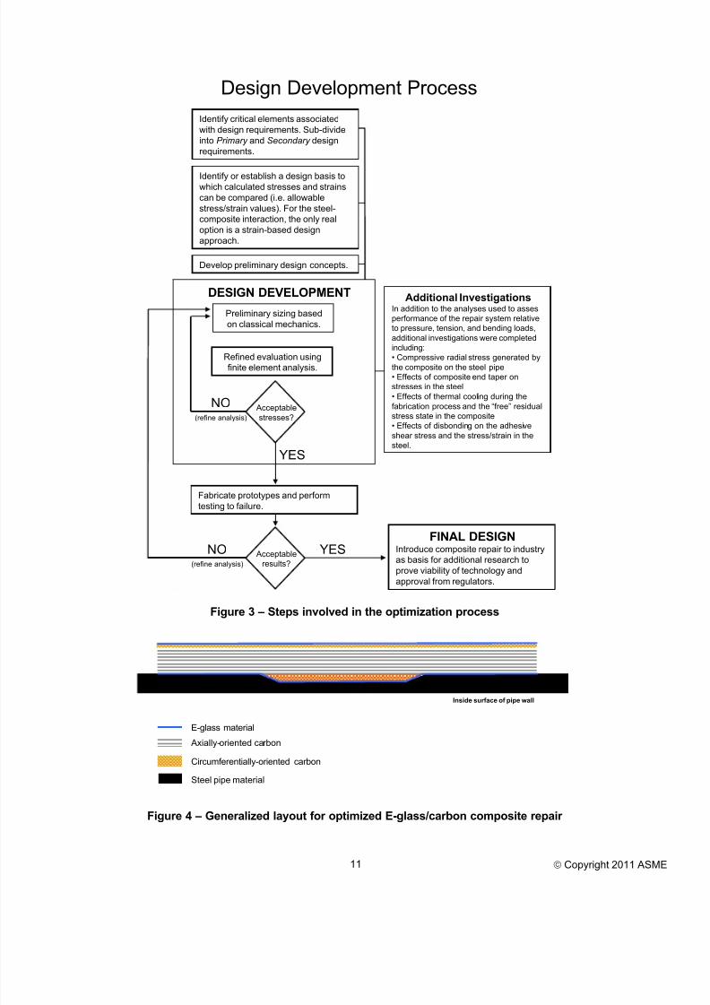
Figure 3 presents the steps involved in the design process. Because of
the unique nature of this process, no single design document exists thatcan designate the design requirements for a composite repair in a prescriptive manner. This process involves both design efforts as well
as identification of a design limits to which the calculated stresses andstrains can be compared. Included in Figure 3 are details initiating atthe preliminary design phase through completion of the final designverified using finite element analysis and prototype testing.
The sections that follow provide details on the design requirements foran optimized composite repair system. Also included are discussions on
the development of a method for determining the allowable designstress and strain values. Finally, the proposed composite architectureand geometry for the optimized system are prescribed.
Design Requirements
In order to develop an optimized repair system, it is first necessary toidentify what is required of the design. Provided below are two levels
of design requirements. The Primary Requirements are those thatgovern the structural design of the composite repair. They effectivelydetermine the composite architecture and geometric options of therepair. The next group, Secondary Requirements, is important in terms
of how the repair functions and performs in situ. Once the PrimaryRequirements are satisfied, the design can proceed to optimization byaddressing the Secondary requirements.
Primary Requirements1. Design must prevent bulging of the corroded pipe section due to
excessive circumferential strains during pressurization. This can be achieved by placing circumferentially-oriented fibers close tothe corroded region.
2. The repair must provide sufficient reinforcement so that strainsinduced during bending do not exceed a specified design strain.
One option is to perform a limit state design that includes all loads(pressure, tension, and bending) and change only one load type(e.g. bending) while holding the other two constant. If thecalculated collapse load is greater than the required design load
then a sufficient level of reinforcement exists.3. Design must be of sufficient length to maintain integrity of the
interface bond between the repair and steel. It should be noted thatfrom a mechanics standpoint, this is the least critical of the three
provided primary requirements.
Secondary Requirements4. Ease of installation
5. Economic viability6. Quality control and design to ensure structural integrity during
installation7. Impact resistance
8. Does not cause corrosion or form a galvanic cell, but actually actsas a coating
Method for Determining Allowable Design StatesOne of the challenges in developing a repair system that possessesadequate strength and stiffness to reinforce a given pipe section
involves determining acceptable stress and strain conditions in the steeland reinforcing composite materials. It is clear that the design of therepair must take into account these allowable conditions, especiallywith regards to geometry and architecture of the composite materials.
Fundamentally, there is a balance between having enough material toensure that strains in the steel are minimized, but at the same time not
installing an excessive amount of composite reinforcing materials. Inother words, an optimum design is one that has enough material to meethe design requirements and ensure that strains in the reinforced steelare maintained below an acceptable threshold, but not has more
composite material than is required. Having a thorough understanding
of the mechanics of the problem, along with the integration of availableindustry-accepted allowable conditions, is the key to achieve asuccessful design.
The two keys to achieving an optimum design relative to allowableconditions in the steel and composite materials are found in thefollowing:
• Determining the maximum acceptable strain in the steel subject toappropriate pressure, tension, and bending loads
• Defining the maximum allowable stress in the compositereinforcing material
Limit analysis methods were used to determine acceptable designconditions, but also to optimize a carbon-epoxy repair system.
Strain Limitations for the Repaired Steel SectionOne of the primary purposes when performing any structural repair isreduction of loads carried by the reinforced member. In providingreinforcement, the primary load path is no longer carried solely by theoriginal member, but loads are also carried by the addition of the
composite reinforcement. Strain is the best mechanics-based quantity toassess the distribution of load between the primary load carrying
component (i.e. steel riser pipe) and the repair system (i.e. composite).
With the addition of the composite material, it is expected that strainlevels in the riser pipe will be reduced. Under normal operating
conditions, limitations are imposed on stress, typically as percentagesof the material yield strength. Limit analysis methods permit theassessment of a structure to take into account some level of plasticity toachieve greater use of the steel’s capacity, but also some level of
plasticity is needed to transfer a portion of the total load from the steeto the composite material.
EVALUATING THE OPTIMIZED REPAIR SYSTEMThis paper has presented details on the design requirements associatedwith developing a composite repair system. This section providesspecific details on how a composite repair system (hereafter referred toas the CRA system) was designed and evaluated relative to a pre-
established set of design criteria. For the problem at hand thifundamentally involved determining the appropriate fiber orientationand thickness to resist internal pressure, tension, and bending loads
associated with the operation of an offshore riser. The evaluation process used strength of materials, along with finite element modelingto determine the best configuration for reinforcing the corroded riser.
The following sections provide details on the analysis, fabrication, andtesting of the CRA repair system. Through experimental verificationthe design methods and resulting composite repair system are evaluated
using prototype fabrication and full-scale testing.
Preliminary ConceptsProvided below are elements of the composite repair system design fo
the specific pipe geometry evaluated in this study. The materials for theoptimized design integrated a combination of carbon and E-glass fibers1. Inner and outer layers of E-glass. The inner layer acts to protec
the pipe from potential corrosion due to carbon interaction with
8/13/2019 2011 Oct - Alexander, C., Et Al - IOPF2011-7002-Houston
steel (i.e. formation of a galvanic cell), while the outer layers protect the carbon fibers.
2. Circumferentially-oriented carbon fibers placed in the region ofcorrosion.
3. Outside of the inner circumferential fibers, the majority of thefibers are oriented axially to provide rigidity in bending and
tension.
4. The length of the repair should be at least 16 inches on each sideof the corroded region. A repair length of 60 inches was selected, providing 18 inches on each side of the 24-inch long corroded
region.5. The following thicknesses are used for the CRA optimized design,
hereafter referred to as the CRA system (see Figure 4 forarchitecture details).
a. Inner layer of 50-50 E-glass, spiral wrap, ~ 0.030 inches thick b. Circumferential carbon (stitched fabric), 0.200 inches thickc. Axial carbon (pre-cured half shells), 0.400 inches thick
d. Circumferential-spiral carbon (stitched fabric), 0.100 inchesthick
e. Outer layer of 50-50 E-glass, spiral wrap, ~ 0.030 inches
thickThe CRA system design has the benefits of a wet lay-up in terms of
strength potential; however, the quality control is improved for thecarbon half-shells when compared to field applications. Additionally,
the time required for installation is reduced. Classical mechanics wereused to optimize the design in terms of loads that include internal
pressure, tension, and bending. ASME B31.8 was used to establish thedesign criteria for the 8.625-inch x 0.406-inch, Grade X46 pipe. The
internal pressure, tension, and bending requirements were calculated to be 2,887 psi, 145,000 lbs, and 50,000 ft-lbs, respectively. For thesedesign conditions the optimized prototype was analyzed.
Assessment Based on Finite Element MethodsOnce the calculations were completed using classical mechanics, afinite element model was developed to determine the following:
• Stress and strain in the composite material considering design loadconditions
• Strain in the steel considering design load conditions
• Confirming that the 0.200 inch thick hoop-oriented fibers weresufficient for the required design conditions
• Assess the effects of different thicknesses of the axially-orientedfibers (important for evaluating bending load rigidity)
To assess performance of the repair subject to design loads, a finiteelement models was analyzed for the CRA system that includedinternal pressure (2,887 psi), axial tension (145,000 lbs), and a range of
bending forces. A four point bend configuration was used in the finite
element model, so to compute the applied bending moment the appliedforce is multiplied by 2.92 feet (i.e. 10,000 lbs corresponds to a
bending moment of 29,200 ft-lbs). There are several noteworthyobservations in reviewing the data plotted in Figure 5 that are listed
below.• The data corresponding to the unrepaired condition (solid red
curve) did not include pressure. This was to mimic the test program that did not include pressure during the bend test for the
unrepaired case. If pressure had been applied, an excessively low bending capacity would have resulted for the corroded unrepairedcase due to gross plastic yielding in the steel.
• The primary source of the design limits is based on the uncorroded base pipe data (green line). From this case the design load is
calculated. As noted in the figure, the following data points aredetermined:o Plastic analysis collapse load of 33.6 kips.
o Design load (bending force) of 16.8 kips (design margin of2.0 on the collapse load) which also corresponds to a bending
moment of 49.1 kip-ft.o At the design condition, the maximum permissible axia
strain in the steel beneath the repair is 0.214 percent(corresponds to the intersection of the horizontal line
designating the design load and the double elastic curve).
Figure 6 shows the maximum principal strain in the steel at loads equato the design and plastic collapse loading conditions. There are several
noteworthy observations in viewing this figure.
• At the design condition, the maximum strain in the steel that isobserved beneath the composite repair is 0.17% (based on the
plotted contour data). It should be noted that if the composite
reinforcement were not present, the deformation in this regionwould exhibit gross yielding.
• Once the plastic collapse load is reached, the maximum strainoccurs outside the corroded and reinforced region. Once thiscondition is reached, the composite reinforcement carries a
significant portion of the bending load and the maximum bendingstrain in the pipe actually occurs outside the composite reinforcedregion.
In summary, the following design limits are imposed on the CRAsystem design:
• Carbon/epoxy material stress limit of 40,000 psi (in accordancewith the methods outlined in ASME STP/PT-005 Design FactoGuidelines for High Pressure Composite Hydrogen Tanks), which
corresponds to a strain limit of 0.40 percent.
• Strain limit on corroded steel beneath the reinforcement of 0.214
percent
• The maximum permissible bending load (based on designconditions with a design margin of 2.0 on the collapse load) is
16.8 kips
Fabrication and Installation of the Prototype RepairThis section provides documentation including details on fabricationand installation of the hybrid E-glass/carbon half-shells, results fromthe full-scale test program, correlation with finite element results, and ageneral discussion on the overall performance of the CRA repai
system relative to design margins. An epoxy resin matrix was used inall layers of the system. It includes the pre-cured carbon half shells, aswell as all other layers applied as wet lay-ups located beneath and on
top of the half shells.
Fabrication EffortsSix (6) carbon half shells, each 60 inches long, were fabricated atComptek Structural Composites, Inc.’s facility in Boulder, ColoradoThe architecture of the half-shells uses an inner single layer of E-glass
balanced weave cloth that is approximately 0.050 inches thick. On top
of this inner layer the uniaxial carbon stitched fiber cloth of 0.400inches was installed, which corresponds to a total of 20 layers. Thehalf-shells were cured under a vacuum seal. The completed half shellswere shipped to Stress Engineering Services, Inc. in Houston.
The following material data were measured for the carbon materiausing ASTM D-3039.Tensile strength: 88,336 psi (standard deviation of 5,485 psi)Elastic modulus: 8,696 ksi (standard deviation of 503 ksi)
Elongation: 1.02 percent (standard deviation of 0.05 percent)
This material was also applied as a wet lay-up material beneath the halshells on the pipe in the corroded region to provide hoop reinforcement
8/13/2019 2011 Oct - Alexander, C., Et Al - IOPF2011-7002-Houston
and also positioned circumferentially on the outside surface of the halfshells.
Installation EffortsPrior to testing and installation of the repair system, three (3) steel pipetest samples were fabricated. The samples were fabricated using 8.625-
inch x 0.406-inch, Grade X46 pipe. A 50 percent simulated corrosion
circumferential groove spanning 24 inches in length was machined ineach sample. The samples configurations were as follows:
• Burst sample with a length of 8 feet
• Tension sample with a length of 8 feet
• Bending sample with a length of 15 feet
Strain gages were installed on each of the above test samples withdetails provided in a following section of this paper.
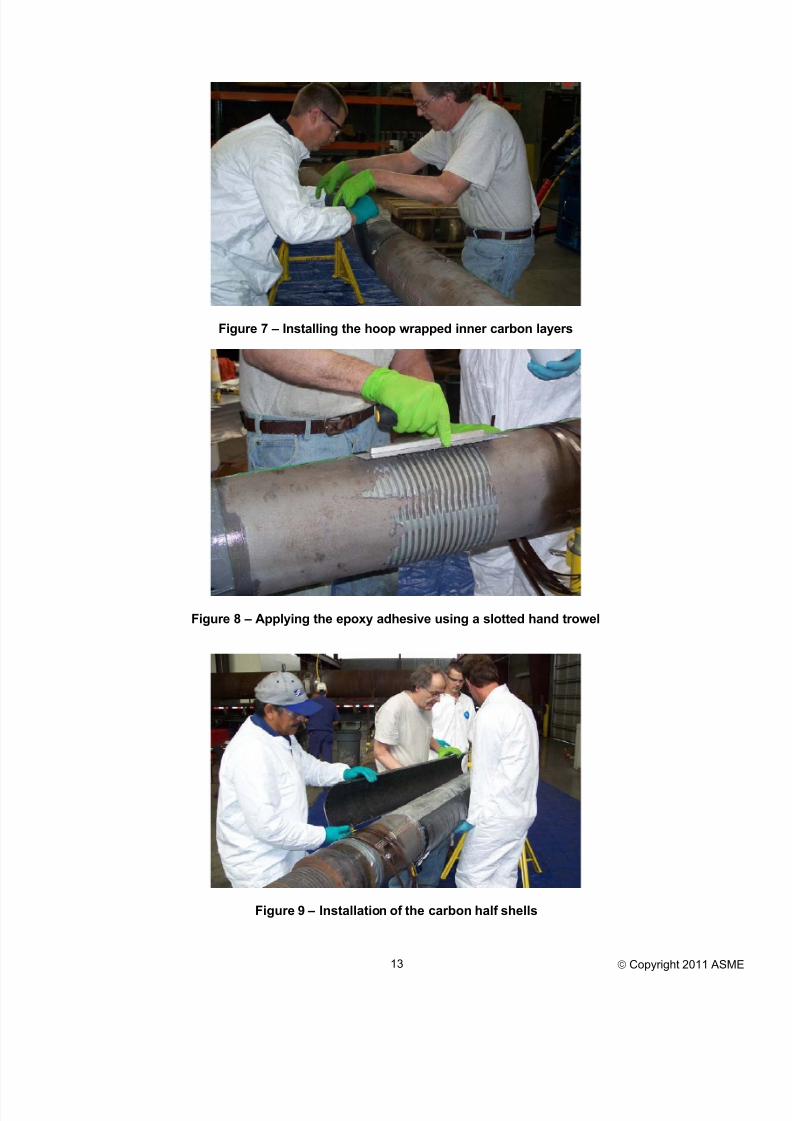
The following steps were involved in the installation of the repairs.Figures are referenced that include photos for each step as appropriate.1. Sandblast the surface of the pipe where the composite repair to be
installed.2. To repair the 24 inch long corroded section of pipe, the uniaxial
stitched carbon cloth material was cut to length. Repairs were
made by saturating the cloth with two part epoxy and wrapping thecloth around the pipe in the hoop direction. Two rows of material,
each totaling 10 layers, were installed in the damaged region asshown in Figures 7 to produce a total thickness of 0.200 inches.
3. Blue plastic stricter wrap material was applied over the outsidesurface of the hoop wrapped material. Perforation of the plastic
wrap was done to permit the excess resin to extrude. The hoopwrapped material was permitted to cure overnight.
4. After the stricter wrap material was removed, the Spabond 340
two-part epoxy was mixed using a mixing gun. The mixed grayepoxy was hand applied using a slotted trowel with ¼-inch by ¼-inch square grooves as shown in Figure 8.
5. The carbon half shells were installed on the outside surface of the pipe. The 60-inch long half shells were centered axially on thecorroded region. Figure 9 shows the carbon half shells beinginstalled on the 8-ft long tension sample.
6. Steel banding clamps were installed on the outside surface of thecarbon half shells to restrain them during curing. To expedite theinstallation process, the banding clamps were left on the half shells
beneath the outer hoop wrapped layers.
7. Once the carbon half shells were locked in place with the steel banding clamps, the outer hoop wrapped carbon material wasinstalled. The same materials used previously for the innercorrosion hoop layers were used in this layer (uniaxial stitched
carbon with an epoxy matrix); however, only 5 layers wereinstalled resulting in a total thickness of 0.100 inches. Five rowsof carbon material were installed that resulted in a small axial 1.5inch gap between each of the layers. Stricter wrap material was
installed on the outside surface of the hoop wraps.
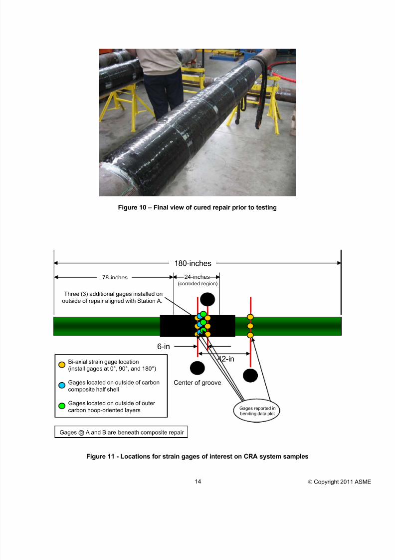
8. The samples were permitted to cure overnight and the stricterwrap was removed the following morning. Figure 10 shows thefinal repair including the carbon half shells and outer carbon hoop
wrapped material.
Samples were permitted to cure for a full 24-hour period before testing
was started. During the curing phase, the necessary cables andinstrumentation were connected to the data acquisition system used torecord data during testing.
Evaluation Based on Full-scale Testing MethodsBiaxial (i.e. hoop and axial) strain gage rosettes were used in testing todetermine the level of strain in the pipe steel and composite materials.The strains they measure provide information that determines if a
composite repair system is functioning as designed. Strain gages wereinstalled on three different stages including (1) prior to installation of
the repair, (2) installed on the carbon half shells, and (3) on the surfaceof the hoop-wrapped carbon layers installed on the outside surface othe repairs.
Figure 11 is a schematic showing the location of the strain gages
installed on the CRA system test samples. Note that six total gages arelocated on the outside of the repair. Three of these are on the outsidesurface of the pre-cured carbon shell, while three are placed on the
outside surface of the carbon hoop material (this composite materia placed over the carbon half shells to restrain them).
Presented in this section of the paper are detailed discussions on the
strain gage results measured for samples repaired using the CRAsystem during the pressure, tension, and bending tests, respectively. Afollow-up discussion provides comparison of results with those
calculated for the system using finite element methods.
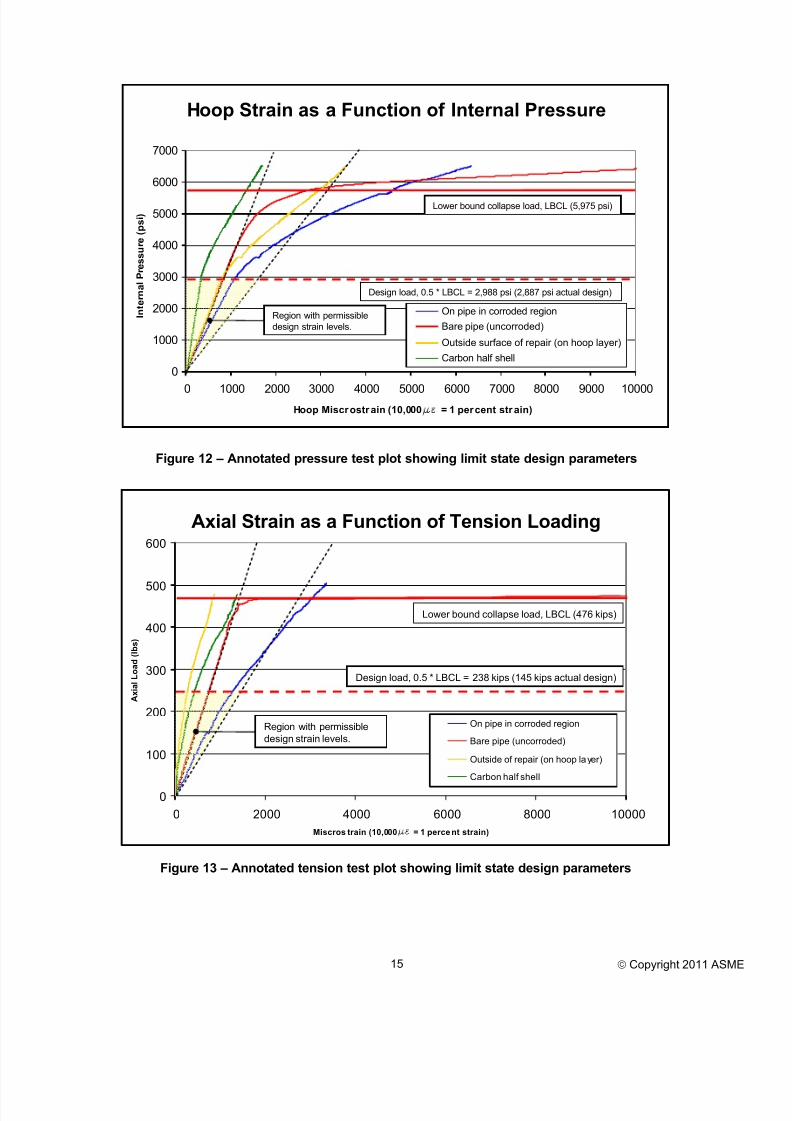
Burst Pressure Test ResultsFigure 12 plots hoop strain measured in the steel on various sections inthe CRA composite repair system during the burst pressure test. The
measurements associated with the following hoop strain gages areincluded in this plot.
• On steel beneath the repair in the corroded region of the pipe
• On the bare pipe outside of the repair (represents results for anundamaged pipe)
• Outside surface of the repair on the outer carbon hoop wrap (axiacenter)
• On the carbon half shell beneath the outer carbon hoop wrap (axiacenter) – noted as the carbon half shell in the figure legend
There are several noteworthy observations that are made in viewing thestrain gage results presented in Figure 11.
• The ideal level of reinforcement is one that parallels the initiaresponse of the uncorroded bare pipe (RED curve). The plotteddata for the strain gage results in the corroded region (BLUE
curve) show the level of reinforcement that is provided by therepair system.
• Results are presented for the strain gage placed on the carbon halshell (GREEN curve). It is observed that the hoop strain in thiscomponent of the repair with axial carbon fibers does not measure
the same level of strain observed in the other layers dominated byhoop-oriented fibers. This is to be expected as the intent in thedesign is for the inner hoop layers to provide reinforcement toreduce bulging the corroded region of the pipe.
• Strain gages were installed on the outside surface of the 0.100 inchthick carbon hoop wrap. The purpose of these layers was torestrain the carbon half shells to the pipe. The strain gage resultsshows for these gages (GOLD curve) clearly demonstrate tha
they are being loaded and that the outer layers are provide restrain
to the carbon half shells.
Some final comments are warranted regarding the acceptability of theCRA system design. As discussed previously, in limit state design alower bound collapse load (LBCL) is selected using the double elastic
slope method. This method is used to determine the LBCL based on theelastic response of the loaded structure. The plotted data is annotatedand plotted in Figure 12 showing the collapse and design loads. Thelower bound collapse load is calculated to be 5,975 psi and the resultingdesign load is 2,988 psi. The previously determined design pressure for
the base pipe is 2,887 psi, which is 97 percent of the calculated limitstate design pressure.
8/13/2019 2011 Oct - Alexander, C., Et Al - IOPF2011-7002-Houston
Also provided in the figure is a highlighted region showing theacceptable design pressure and strain levels. It is important to note that
the strain in the corroded region of the test sample exists within thisregion, demonstrating that adequate reinforcement is provided by thecomposite repair system.
A final comment concerns the level of strain measured in the carbon
reinforcement, especially the layers placed directly against the pipe inthe corroded region. From a long-term performance standpoint, thestrain in the carbon must be limited to be less than 40 percent of the
breaking strength of the composite material. For the carbon materialused in this repair, the strain must not exceed 0.40 percent. As shown inFigure 12, at the design pressure the maximum strain in the hoopwrapped materials are significantly less than this value. At most, the
maximum hoop strain is 0.13 percent.
Tension Test ResultsFigure 13 plots axial strains measured during loading of the tensiontest sample (strain gages in this plot are the same as those presented
previously for the pressure-only test sample). There are several
noteworthy observations that are made in viewing the strain gageresults presented in Figure 13.
1. As expected, the maximum strain occurs in the corroded steelregion of the sample beneath the repair. From the beginning of
loading this region carries a greater percentage of load thanobserved in the composite materials; however, it should be notedthat if the composite material were not present the sample wouldhave failed at approximately 320 kips, a value on the order of 50
percent of the 594 kips failure load recorded for this particularsample.
2. Due to the relative stiffness of the steel in comparison to thecomposite, during the initial stages of loading it carries a higher
percentage of the load. However, as yielding occurs in both thecorroded region and the base pipe, a greater percentage of the loadis distributed to the composite material. This is observed in Figure
13 where the base pipe (RED curve) starts yielding atapproximately 450 kips. At this point, axial strains in the carbon
half shell (GREEN curve) are increased, indicating that thecarbon half shell material is carrying an increased percentage of
the load.3. Axial strains measured in the outer hoop wrapped carbon are less
than those measured in both the pipe (corroded and uncorroded)and the carbon half shells. This is to be expected as this region is
the last to be loaded during the process of applying the axialtensions loads.
Figure 13 includes the limit state design details. Even though the final
failure occurred at 594 kips, the LBCL is calculated as 476 kips.Considering the combined load state, this calculated value is notnecessarily over-conservative. Based on the calculated LBCL, thedesign load is calculated to be 238 kips. This value is 64 percent greater
than the specified design load of 145 kips. Figure 14 provides a seriesof photographs from the tension testing phase of work.
Also provided in the figure is a highlighted region showing the
acceptable design pressure and strain levels. It is important to note thatthe strain in the reinforced corroded region (BLUE curve) generallyexists within the acceptable design region, demonstrating that adequatereinforcement is provided by the composite repair system. Another
observation is that the strain in the composite material is less than 0.20 percent for all levels of loading, a value less than the 0.40 percent
allowable strain for the carbon material.
Bend Test ResultsResults are plotted for the bend test results. Figure 15 plots axia
strains measured during loading of the bending test sample. Note thaduring testing an internal pressure of 2,887 psi and an axial tension of145 kips were included in addition to the bending load. Strain gages inthis plot are the same as those presented previously for the pressure-
only and pressure-tension test samples.
The following observations are made in viewing the results plotted inFigure 15. It should be noted that for the four-point bending
configuration, the bending moment is calculated by multiplying the bending load by 35 inches (or 2.92 feet).
• At a bending load of approximately 20 kips all strain gagesdemonstrate deviation from the proportional limit (i.e. response is
no longer elastic). This is consistent with hand calculations thashow at a bending load of 25 kips yielding occurs in the 46 ksyield strength pipe.
• As expected, the maximum strain occurs in the corroded region ofthe test sample beneath the repair (BLUE curve). At a bending
load of 40 kips, the axial strain is measured to be 2,000microstrain (0.20 percent).
• The strain in the carbon half shell (GREEN curve), although less
than the strain in the reinforced steel, demonstrates that it isengaged with increasing bending loads.
Another important observation is that as the bending load is increasedthe axial strains in the region of the reinforcement (i.e. everythingexcept the RED curve) do not increase proportionally with increasing
bending loads. The basis for this observation is that once a plastic hingeforms in the pipe (1.5 times the yield load, or approximately 65 kips),deformation initiates in the base pipe away from the composite repair
Additional loading only acts to plastically deform the pipe at the pointsof contact with the hydraulic cylinders and not transfer load into thereinforced region. This is a critically important observation as i
indicates that the actual plastic collapse of the pipe will not occur in therepaired region, but rather outside the repair zone where local bendingstresses are the greatest.
Figure 15 includes the strain gage data overlaid with the limit load parameters including the lower bound collapse load and thecorresponding design load. Within the range of acceptable strain levelsthe reinforcement provided by the CRA system is adequate. Because o
the relatively low lower bound collapse load observed experimentallyall strains in the reinforced region of the sample are below the strainsobserved in the base pipe away from the reinforcement. This isimportant as it demonstrates that the reinforcement is functioning as
intended and providing reinforcement to the corroded region of the tessample. Table 2 provides a comparison of results from both theanalysis and testing efforts for the CRA system. The results are fostrains in the reinforced region of the steel. In this table results are only
presented for the burst and bending tests, as the tension to failure tes
was primarily an assessment of the shear strength of the adhesive bonding the carbon half shell to the steel pipe. What is important to
note is that, in general, all measured strains are less than thosecalculated using finite element methods, including the results for boththe design and limit load conditions. The exception to this observationis the strains recorded for the burst sample near the limit load of 5,700
psi (actual burst occurred at 6,517 psi).
A final comment is warranted with regards to design requirements fothe carbon material. Note that in both strain gages installed on the
composite material the recorded strain levels never exceed 0.30 percent, a value less than the 0.40 percent allowable strain for thecarbon material.
8/13/2019 2011 Oct - Alexander, C., Et Al - IOPF2011-7002-Houston
FUTURE WORKOne of the primary purposes of this paper is to communicate details on
an upcoming study being co-sponsored by the Pipeline ResearchCouncil International, Inc. (PRCI) and four composite repairmanufacturers. The program of interest is the MATR-3-6 study focusedon evaluating the repair of offshore pipelines and risers using
composite materials.
The proposed work scope is an extension of a previous 2006 research program co-sponsored by the Minerals Management Service – MMS
(now known as the Bureau of Ocean Energy Management, Regulationand Enforcement - BOEMRE) and four manufacturers [28]. In this
previous program composite materials were used to repair 50%corrosion in test samples subjected to pressure, tension, and bending
loads. This program picks up where the prior study left off; the primaryenhancements of the current study include the subsea repair element, aswell as storing the samples in a tank filled with water for 10,000 hours.
Listed below are several objectives of the current study that will either be addressed during testing or commented upon in the final report.
• Address issues related to long-term performance, especially withregards to design conditions for the composite repair.
• Installation by divers based upon feedback from operators andmanufacturers. Several operators also showed interest inevaluating the ability of ROVs to install composite materials.Although ROV-installed repairs are outside the scope of this
particular study, this topic will be discussed and can hopefully be
addressed in future PRCI work.
• The effects of temperature on performance of the compositematerial. Most manufacturers indicated to SES that a vast majorityof their repairs take place in the splash zone in Gulf of Mexico
water, indicating that temperature is not an issue.
• Addressing the effects of surface cleanliness and the presence ofsilt on the lapshear strength of the adhesive materials.
• The issue of collapse seems unlikely at water depths at whichcomposite materials are currently installed.
Figure 16 is a schematic diagram of the axial 8-ft burst and tensionsamples used in the previous MMS study showing the associatedcorrosion regions. The same basic configuration will be used in thecurrent program. Figure 17 is a schematic diagram showing the
proposed testing facility where samples having 50% corrosion will be pressurized for 10,000 hours and then removed for testing. At that point
the test samples will be tested to failure including burst tests, tension tofailure tests, and bend testing. Strain gages will be used, as with the
previous MMS testing, to evaluate the level of performance of eachrespective composite repair system.
CONCLUSIONS Extension of onshore composite repair techniques to offshore risers by
developing integrated analytical and experimental methods isaccomplished by designing a carbon-based composite repair systemincorporating computational simulation, prototype fabrication andexperimental verification, numerical simulation, and prototype testing.
Furthermore, guidelines for industry in repairing and reinforcingoffshore risers using composite materials are developed.
Data for strain, deflection, pressure, and bending/tensile forces wererecorded during testing. The data were post-processed and compared to
the analysis results and both data sets were shown to have goodagreement. An additional benefit in comparing the testing and analysisresults was confirmation of the analysis methods, as well asdemonstrating that the failure loads of the tests pieces validated the
safety of the selected design margins. The conclusion is that the CRAsystem satisfied the research objective and that it is possible to repai
offshore risers using composite materials. These repairs can be made insitu using the technology presented in this paper.
The CRA system study, along with the ongoing PRCI program, is a
clear demonstration of several important observations. First, the
original impetus for this study was concern from government regulatorsregarding the safety and acceptability of composite materials inreinforcing corroded offshore risers. Secondly, this study shows how
industry, academia, and regulators can work together to develop repairmethods based on sound engineering judgment. An eventual outcome ofthis effort was the development of a design basis based on numerica
simulation that can be used by others to develop robust repair systems
for safely repairing offshore risers subject to combined loads. Finallythis study indicates that a systematic method can be used to develop anoptimized composite repair system using classical mechanics, finite
element methods, and full-scale testing. The validation processinvestigated in this study leads to improved confidence so that industrycan benefit from the use of composite materials in reinforcing and
repairing offshore riser systems. Finally, the forthcoming PRCI studywill generate critical information necessary for determining the long
term viability of the composite repair technologies.
REFERENCES1. ASME B31.4. Liquid Transportation System for Hydrocarbons,
Liquid Petroleum Gas, Anhydrous Ammonia and Alcohols. New
York: American Society of Mechanical Engineers; 2003.2. ASME B31.8. Gas Transmission and Distribution Piping Systems.
New York: American Society of Mechanical Engineers; 2003.3. ASME B31G. Manual for Determining the Remaining Strength of
Corroded Pipelines. New York: American Society of MechanicalEngineers; 1991.
4. Sparks, C.P.. Lightweight Composite Production Risers for aDeep water Tension Leg Platform, .Proceedings of the OffshoreMechanics and Arctic Engineering Conference Proceedings,
Tokyo, Japan, p. 86 - 93.5. Sparks C.P., Odru P., Mechanical Testing of High-Performance
Composite Tubes for TLP Production Risers, OffshoreTechnology Conference Proceedings, Paper No. OTC 5797,Houston, Texas, May 2 – 5, 1988. p. 467 – 72.
12. Alexander, C. R., and Francini, R., State of the Art Assessment ofComposite Systems Used to Repair Transmission Pipelines, Paper
No. IPC2006-10484, Proceedings of the 6th International PipelineConference, September 25-29, 2006, Calgary, Alberta, Canada.
13. Hyer, M.W., Stress Analysis of Fiber-Reinforced Composite Materials, New York: WCB/McGraw-Hill; 1998.
14. Agarwal, B. D., and Broutman, L.J., Analysis and Performance of
Fiber Composites (Second Edition), New York: John Wiley &Sons, Inc.; 1990.15. McGarry, F.J., Crack Propagation in Fiber Reinforced Plastic
Composites, Fundamental Aspects of Fiber Reinforced Plastics. New York: Interscience; 1968.
16. Broutman, L.J., Sahu ,S., Progressive Damage of a Glass Reinforced Plastic During Fatigue, SPI Technical Conference
Proceedings, Washington, D. C., 1969. p. 210 – 32.17. Smith, T.R., Owen, M.J., Progressive Nature of Fatigue Damage
in RP , Modern Plastics, 1969; 46(5): 1281 – 1331.
18. Broutman, L.J., and Mallick, P.K., Impact Behavior of HybridComposites, SPI Annual Technical Conference, Washington, D.C., 1975, Section 9-C. p. 193 – 99.
19. Gao, M, Xu, C., Du, Z., and Wang, T., Contact Corrosion Between Carbon Fiber Reinforced Composite Materials and
High-Strength Metals, National Air Intelligence Center Wright-Patterson Air Force Base, Dayton, Ohio, August 9, 1995.
20. Steckel, G.L., and Hawkins, G.F., The Application ofQualification Testing, Field Testing, and Accelerated Testing for
Estimating Long-Term Durability of Composite Materials forCaltrans Applications, Prepared for the State of California
Department of Transportation by Space Materials Laboratory,Contract No. 59A0188, February 25, 2005.
21. 2006 Design Factor Guidelines for High-Pressure Composite Hydrogen Tanks, American Society of Mechanical Engineers;
New York, 2006.22. ASTM D2992, Standard Practice for Obtaining Hydrostatic or
Pressure Design Basis for Fiberglass (Glass-Fiber-ReinforcedThermosetting-Resin) Pipe and Fittings, ASTM International,
2001.Mraz, G.J., Development of Design Criteria for a High
Pressure Vessel Construction Code, JPVT. 1987; 109: 256 – 59.23. ASME Boiler and Pressure Vessel Code, Section VIII, Division 3:Alternative Rules for Construction of High Pressure Vessels. New
York: American Society of Mechanical Engineers; 2004.24. Gerdeen, J.C., A Critical Evaluation of Plastic Behavior Data and
a Unified Definition of Plastic Loads for Pressure Components,WRC Bulletin 254. New York: Welding Research Council, Inc.;
1979.25. Kalnins, A, Guidelines for Sizing of Vessels by Limit Analysis,
WRC Bulletin 464. New York: Welding Research Council, Inc.;
1. Design Strain Limit based on finite element results for undamaged pipe subject to specified loading.2. Experimental Measured Strains were extracted from strain gage positioned on steel beneath composite repair in center of