24
Multi-Mobile Network Operator In-Building LTE Remote Radio Head Technical Requirements Version 1.00 3 April 2012
| Date post: | 17-Jul-2016 |
| Category: |
Documents |
| Upload: | frensel-petrona |
| View: | 3 times |
| Download: | 2 times |

Multi-Mobile Network Operator In-Building
LTE Remote Radio Head Technical
Requirements
Version 1.00
3 April 2012

Hotel Technology Next Generation Multi-Mobile Network Operator In-Building
LTE Remote Radio Head Technical Requirements
3 April 2012 Version 1.00
Page 2
About HTNG
Hotel Technology Next Generation (HTNG) is a non-profit association with a mission to foster, through collaboration
and partnership, the development of next-generation systems and solutions that will enable hoteliers and their
technology vendors to do business globally in the 21st century; to be recognized as a leading voice of the global hotel
community, articulating the technology requirements of hotel companies of all sizes to the vendor community; and to
facilitate the development of technology models for hospitality that will foster innovation, improve the guest
experience, increase the effectiveness and efficiency of hotels, and create a healthy ecosystem of technology suppliers.
Copyright 2012, Hotel Technology Next Generation
All rights reserved.
No part of this publication may be reproduced, stored in a retrieval system, or transmitted, in any form or by any
means, electronic, mechanical, photocopying, recording, or otherwise, without the prior permission of the copyright
owner.
For any software code contained within this specification, permission is hereby granted, free-of-charge, to any person
obtaining a copy of this specification (the "Software"), to deal in the Software without restriction, including without
limitation the rights to use, copy, modify, merge, publish, distribute, sublicense, and/or sell copies of the Software, and
to permit persons to whom the Software is furnished to do so, subject to the above copyright notice and this
permission notice being included in all copies or substantial portions of the Software.
Manufacturers and software providers shall not claim compliance with portions of the requirements of any HTNG
specification or standard, and shall not use the HTNG name or the name of the specification or standard in any
statements about their respective product(s) unless the product(s) is (are) certified as compliant to the specification or
standard.
THE SOFTWARE IS PROVIDED "AS IS", WITHOUT WARRANTY OF ANY KIND, EXPRESS OR IMPLIED, INCLUDING BUT NOT
LIMITED TO THE WARRANTIES OF MERCHANTABILITY, FITNESS FOR A PARTICULAR PURPOSE, AND NON-INFRINGEMENT.
IN NO EVENT SHALL THE AUTHORS OR COPYRIGHT HOLDERS BE LIABLE FOR ANY CLAIM, DAMAGES, OR OTHER LIABILITY,
WHETHER IN AN ACTION OF CONTRACT, TORT OR OTHERWISE, ARISING FROM, OUT OF, OR IN CONNECTION WITH THE
SOFTWARE OR THE USE OR OTHER DEALINGS IN THE SOFTWARE.
Permission is granted for implementers to use the names, labels, etc. contained within the specification. The intent of
publication of the specification is to encourage implementations of the specification.
This specification has not been verified for avoidance of possible third-party proprietary rights. In implementing this
specification, usual procedures to ensure the respect of possible third-party intellectual property rights should be
followed.
The names Hotel Technology Next Generation and HTNG, and logos depicting these names, are trademarks of Hotel
Technology Next Generation. Permission is granted for implementers to use the aforementioned names in technical
documentation for the purpose of acknowledging the copyright and including the notice required above. All other use
of the aforementioned names and logos requires the permission of Hotel Technology Next Generation, either in written
form or as explicitly permitted for the organization’s members through the current terms and conditions of
membership.

Hotel Technology Next Generation Multi-Mobile Network Operator In-Building
LTE Remote Radio Head Technical Requirements
3 April 2012 Version 1.00
Page 3
A special thanks to the HTNG members who have contributed to the development of this
requirements document as well as supporting Cellular Coverage Workgroup efforts:
AT&T
CISCO
Corning MobileAccess
Enseo
Future Technologies Consulting Group, Inc.
Hewlett Packard
Hilton Hotels
Hyatt Hotels
InnerWireless
Mandarin Oriental Hotel Group
Marcus Hotels
Marriott International
Motorola
Omni Hotels
Ruckus Wireless
SOLiD Technologies
Sprint
Starwood Hotels and Resorts

Hotel Technology Next Generation Multi-Mobile Network Operator In-Building
LTE Remote Radio Head Technical Requirements
3 April 2012 Version 1.00
Page 4
Table of contents
1 INTRODUCTION ............................................................................................................................................... 5
2 PROBLEM STATEMENT: TWO YEARS FROM NOW............................................................................... 6
2.1 GUEST ............................................................................................................................................................ 6 2.2 HOTEL ............................................................................................................................................................ 6 2.3 MOBILE NETWORK OPERATOR (MNO) .......................................................................................................... 6 2.4 PERFECT STORM ............................................................................................................................................. 6 2.5 WHAT DOES THIS MEAN FOR EXISTING WAN METHODS? ............................................................................... 6
3 WHY CPRI? ........................................................................................................................................................ 7
3.1 BENEFITS OF C-RAN ARCHITECTURE ............................................................................................................. 7 3.1.1 Energy Efficient ..................................................................................................................................... 7 3.1.2 Cost savings on CAPEX/OPEX ............................................................................................................. 7 3.1.3 Capacity Improvement ........................................................................................................................... 8 3.1.4 Adaptability to Non-uniform Traffic ...................................................................................................... 8 3.1.5 Smart Internet Offload ........................................................................................................................... 8
4 SYSTEM OVERVIEW ....................................................................................................................................... 9
4.1 MRHU ......................................................................................................................................................... 10 4.1.1 Input Interfaces .................................................................................................................................... 10 4.1.2 Outputs ................................................................................................................................................. 10 4.1.3 Connectors ........................................................................................................................................... 11 4.1.4 Management ........................................................................................................................................ 11 4.1.5 Enclosure ............................................................................................................................................. 11
4.2 RRU ............................................................................................................................................................. 12 4.2.1 Connectors ........................................................................................................................................... 13 4.2.2 Coverage & Capacity .......................................................................................................................... 13 4.2.3 Management ........................................................................................................................................ 14 4.2.4 Power ................................................................................................................................................... 14 4.2.5 Enclosure ............................................................................................................................................. 14 4.2.6 Environmental & Regulatory Requirements ........................................................................................ 15 4.2.7 Performance Metrics for both MRHU and RRU (minimum) ............................................................... 15
5 SOFTWARE REQUIREMENTS OVERVIEW: ............................................................................................ 16
5.1 MASTER REMOTE RADIO UNIT (MRRU) ...................................................................................................... 16 5.2 REMOTE RADIO UNIT (RRU) ........................................................................................................................ 17 6.1 A. CPRI AND 3GPP ORI SPECIFICATIONS .................................................................................................... 18 6.2 B. LTE SPECTRUM ....................................................................................................................................... 19 6.3 C. LTE CARRIER AGGREGATION - INFORMATIVE ......................................................................................... 22 6.4 D. LTE TERMINAL CATEGORIES .................................................................................................................. 24

Hotel Technology Next Generation Multi-Mobile Network Operator In-Building
LTE Remote Radio Head Technical Requirements
3 April 2012 Version 1.00
Page 5
1 Introduction
2.3 million hotel rooms are represented by HTNG whose hotel members worked together with
MNOs, DAS manufacturers/ integrators, providers of Wi-Fi, etc. to develop this requirements
document which was created to give RAN/DAS manufacturers insight into hotel requirements to
take an existing architecture (RRH) and adapt it for indoor use by multiple MNOs. This
requirements document is intended to be additive to existing MNO requirement for in building
LTE coverage. In other words, any MNO-specific in building coverage/capacity requirements
should still be met. This requirements document is meant to address the additional
requirements needed for an in building multi-MNO LTE environment.
This document provides high level hardware and software system requirements for distributing
LTE spectrum within a hotel. The notion is that the hotel owner will have participation from
multiple mobile network operators (MNO) and there is a collective interest in improving LTE
coverage and capacity at any given property. There are multiple models for the ownership and
management of the system which are outside the scope of this document. For the purposes of
this document it is assumed that the MNOs would connect to the system on a neutral host
basis.

Hotel Technology Next Generation Multi-Mobile Network Operator In-Building
LTE Remote Radio Head Technical Requirements
3 April 2012 Version 1.00
Page 6
2 Problem Statement: Two Years From Now
2.1 Guest
The mobile device is becoming integral in every aspect of their daily life to:
Conduct business
Enjoy leisure time
Purchase goods and services
Ensure personal safety
2.2 Hotel
Personalized service includes providing connectivity to the network and services of the guest’s
choosing:
Beyond basic Internet access provided by the hotel or its partners
Support quality access to the guest’s subscribed mobile network
Enable delivery of content and services from the Mobile Network Operator
2.3 Mobile Network Operator (MNO)
Service differentiation will come in the form of providing a user real-time control of their
wireless experience:
Good coverage plus the ability to control/mitigate interference
Maximum flexibility in allocating bandwidth
High quality transport medium on premise
2.4 Perfect Storm
With the rollout of LTE, MNO’s are looking at methods of efficient spectrum usage while
keeping their capital costs in check. At the same time, hoteliers are looking to provide indoor
LTE coverage while limiting on-premise LTE electronic equipment.
Base station hoteling satisfies both the MNO and the Hotel. Base station hoteling is a method
whereby remote radio units are deployed in the field or hotel and the remainder of the
electronic equipment remains at the base station co-location site. This concept is analogous to
C-RAN (please see below).
To meet these requirements the document proposes an in-building solution based on the
Common Packet Radio Interface (CPRI). An overview of CPRI and a description of the benefits
offered are provided in the next section.
2.5 What does this mean for existing WAN methods?
The idea of using ethernet for cellular backhaul is becoming mainstay. However, the Base
station hoteling concept cannot use ethernet. The CPRI (3GPP ORI) stack defines its own
physical layer and logical layer (layers 1 and 2).

Hotel Technology Next Generation Multi-Mobile Network Operator In-Building
LTE Remote Radio Head Technical Requirements
3 April 2012 Version 1.00
Page 7
3 Why CPRI?
Today’s MNO networks are evolving. One network solution is the movement away from the
traditional base station architecture to virtual base station architecture where the base station
functionality is split between two elements - the Baseband Unit (BBU) and Remote Radio Unit
(RRU). The migration to virtual base station architecture will most likely occur in stages starting
with the clustering of BBUs to pooling of BBU resources to cooperative processing. The final
stage is often referred to Cloud – Radio Access Network (C-RAN).
3.1 Benefits of C-RAN architecture
3.1.1 Energy Efficient
With the C-RAN architecture, the number of base station sites can be reduced several fold.
Secondly, because the BBU pool is a shared resource among a large number of virtual base
stations, it means a much higher utilization rate of processing resources and lower power
consumption. Lastly, the distance from the RRU to the user’s device can be decreased since
cooperative radio technology can reduce the interference among dense RRUs.
3.1.2 Cost savings on CAPEX/OPEX
Because the BBUs and site support equipment are aggregated in a few big rooms, it is much
easier for centralized management and operation, saving a lot of O&M cost associated with the
large number of base station sites in a traditional RAN. Secondly, although the number of RRUs
may not be reduced in C-RAN architecture, its functionality is simple and size/power are both
small.

Hotel Technology Next Generation Multi-Mobile Network Operator In-Building
LTE Remote Radio Head Technical Requirements
3 April 2012 Version 1.00
Page 8
3.1.3 Capacity Improvement
In the C-RAN architecture, the BBU pool can easily share the signaling, traffic data and channel
state information of all active devices in the system. Hence it’s much easier to implement joint
processing and scheduling to mitigate inter-cell interference and improve spectral efficiency.
3.1.4 Adaptability to Non-uniform Traffic
A C-RAN is also well suited for non-uniform traffic distribution by applying the load balancing
functionality inherently available in pooled architectures.
3.1.5 Smart Internet Offload
The C-RAN architecture enables the break-out of internet traffic at the BBU consolidation point
and therefore reducing core network traffic and gateway upgrade costs, as well as reducing
latency to the user.
The Common Public Radio Interface (CPRI) standard defines the interface between the BBU and
RRU. The CPRI specification is focused on the hardware dependent layers ensuring simplicity,
flexibility, and availability of a wide range of system architectures depending on the application,
as we as, enabling independent upgrades via a standard interconnect.
The adoption of CPRI for in-building solutions not only provides a flexible, scalable in-building
network capable of supporting the unique characteristics of LTE/LTE-A (i.e., wide band, MIMO,
interference mitigation via cooperative radio) for multiple MNOs, but provides a graceful
evolution path to C-RAN

Hotel Technology Next Generation Multi-Mobile Network Operator In-Building
LTE Remote Radio Head Technical Requirements
3 April 2012 Version 1.00
Page 9
4 System Overview
The proposed solution shall use a distributed base station architecture with remote radio heads
installed inside the hotel property. The infrastructure for CPRI (or 3GPP ORI) link between the
Baseband Unit and the Remote Radio Head Units will be the hotel’s fiber.
From a hardware perspective the proposed solution comprises the following components:
Master Radio Head Unit (MRHU)
The purpose of the MRHU is to provide a demarcation point for the MNO on the property,
aggregate CPRI feeds from multiple MNOs and manage the distribution of packet radio data to
intelligent radio endpoints (termed remote radio units) located within the hotel. The MRHU may
also be needed to provide hardware support for advanced features (e.g. dynamic resource
allocation) which will be identified by the software team and incorporated into a later revision of
this document.
It is possible to have multiple Master Remote Radio Heads (MRRH).
Remote Radio Unit (RRU)
The purpose of the RRU is to convert the packet radio data from the MRHU into an analog RF
signal to be propagated from an internal antenna.

Hotel Technology Next Generation Multi-Mobile Network Operator In-Building
LTE Remote Radio Head Technical Requirements
3 April 2012 Version 1.00
Page 10
4.1 MRHU
4.1.1 Input Interfaces
The MRHU shall support four to eight CPRI ports of a type compliant with the CPRI specification.
Input ports may be provided in a modular form factor to provide flexibility and cost control.
Each CPRI port shall be capable of supporting the full CPRI line rate of 10Gbps and shall be fully
configurable to support all line rates defined in the CPRI specification below the maximum line
rate. Each port will be fed from an LTE baseband unit (BBU) that is expected to be owned by the
MNO. The CPRI feed shall support up to two LTE uplink and downlinks channels of 10MHz and
20MHz respectively for up to two bands (e.g. 850MHz/1900MHz). It is recommended that the
minimum line rate from the BBU is 4.9Gbps for one band and 9.8Gbps for two bands. The BBU
may be either located at the MDF or remotely at the MNO switching office.
4.1.2 Outputs
The MRHU shall support up to 48 output ports of a type compliant with the CPRI specification.
Output ports shall be provided in a modular form factor to provide flexibility and cost control.
The number and type of ports required for any line card and number of line card variants is to
Hotel Technology Next Generation Multi-Mobile Network Operator In-Building
LTE Remote Radio Head Technical Requirements
3 April 2012 Version 1.00
Page 11
be determined by the manufacturer. The MRHU shall aggregate the BBU inputs and multicast or
simulcast the composite signal to each of the output ports. The composite signal consists of
multiple CPRI channels carrying control and data signals to the RRUs installed in the property
and shall support up to four EUTRAN Operating Bands as described in Appendix C, LTE
Spectrum.
4.1.3 Connectors
All connectors shall be accessible from the front of the unit.
All fiber connections shall use standard optics as specified in the CPRI specification. The fiber
optics may be for single mode or multi-mode fiber.
Support for multi-mode fiber is required to support the base of multi-mode fiber installed in
hotel properties today. The selection of fiber type needs to consider the higher loss (and
therefore lesser reach) of multi-mode fiber as well as future bandwidth requirements which
may only be achievable with single mode fiber. Appendix B provides a table of the different
characteristics of fiber type.
4.1.4 Management
The MRHU shall be managed by an element management system (EMS). It is envisioned that
network management traffic will be carried over an optical supervisory channel (OSC) between
the RRUs and the MRHU. The MRHU shall have a 1000BASE-T port for connecting to the EMS.
4.1.5 Enclosure
The MRHU will typically be deployed in the MDF of the hotel property being serviced. The MRHU
shall be mounted in a standard 19” rack. The height of the MRHU shall not exceed 2U. The
MRHU shall be powered from a standard AC source supplied at the rear of the unit and should
support dual redundant, hot swappable power supply modules. In addition, the MRHU should
be configurable to support backup power sources such as a generator or UPS to ensure
continued operation in the case of an outage of the primary power source. Power modules shall
be accessible from the front of the unit.

Hotel Technology Next Generation Multi-Mobile Network Operator In-Building
LTE Remote Radio Head Technical Requirements
3 April 2012 Version 1.00
Page 12
4.2 RRU
RRUs can be deployed as standalone endpoints or as participants in one or more of the chaining
topologies defined in the CPRI standard. Chaining RRUs allows the CPRI data to be distributed
across the floor of a building. The purpose of the RRU or RRU chain is to convert the LTE CPRI
input from the MRHU into RF and transmit that signal from a 2x2 MIMO antenna integrated with
the RRU.
The Remote Radio Unit can support up to 4 frequency bands with a minimum of 2 bands, each
with 2x2 MIMO and support for carrier aggregation scenarios up to 20 DL/10 UL MHz per band
(CPRI limitation). The RRU has to support adaptive line rate depending on whether it supports
two, three or four frequency bands. The RF chains can be allocated one per MNO or
concatenated together to provide higher order of MIMO and larger channel size. Each RF Chain
in each Remote Radio Head will be uniquely addressable to support maximum flexibility for
dynamic bandwidth allocation
RRUs are expected to be manufactured in different configurations to allow optimization for
different deployment scenarios i.e. the number of participating MNOs and bands to be
supported. The following configurations have been identified:
Single MNO, single/dual band
Single MNO, multiple bands
Multiple MNOs, single/dual band
Multiple MNOs, multiple bands

Hotel Technology Next Generation Multi-Mobile Network Operator In-Building
LTE Remote Radio Head Technical Requirements
3 April 2012 Version 1.00
Page 13
THE CPRI standard supports interoperability across multiple RRU types. For example, when
MNOs and/or bands cannot share the same RRU, the RRU chains can be configured using
multiple RRU types separated on a fiber daisy chain by wavelength channels. Alternatively,
RRUs may be separated using a physical fiber link.
4.2.1 Connectors
Each RRU shall have a primary CPRI fiber input. In addition, the RRU shall also support
secondary CPRI ports for connecting to other chained RRUs. The supported line rates on the
secondary port shall be same as the input line rate. The number of ports shall be determined by
the type of chaining topology implemented by the equipment vendor, but a minimum of 5 RRUs
per chain is required.
Tree and Branch
Chain
Ring
Primary and secondary CPRI ports shall use standard optics as specified in the CPRI
specification. The fiber optics may be for single mode or multi-mode fiber.
An RRU may also support connectors for an optional 2x2 MIMO antenna to cater to provide
flexibility in deploying the solution in problematic coverage areas.
4.2.2 Coverage & Capacity
For any given CPRI line rate the actual data rates available to a hotel customer will be inversely
proportional to the coverage area provided. In addition, the number of RRUs deployed in a
chain will also impact actual data rates available to a hotel customer as the total CPRI capacity
being presented to the chain will be shared.
Remote Radio Head solution shall meet or exceed Base Unit vendors’ downlink and uplink
spectral efficiency factor for the wireless environment listed above.
Remote Radio Head solution shall meet or exceed the following delay specifications:
Downlink Remote Radio Head Delay Budget = Release 10 3GPP one way downlink budget - BBU
delay - UE delay
Uplink Remote Radio Head Delay Budget = Release 10 3GPP one way uplink budget - BBU delay -
UE delay
Latency: The one-way transit time between a packet being available at the IP layer in either the
UE or radio access network and the availability of this packet at IP layer in the radio access
network/UE shall be less than 5 ms. Also C-plane latency shall be reduced, e.g. to allow fast
transition times of less than 100 ms from camped state to active state management (3GPP TS
25.913 Standard).

Hotel Technology Next Generation Multi-Mobile Network Operator In-Building
LTE Remote Radio Head Technical Requirements
3 April 2012 Version 1.00
Page 14
4.2.3 Management
The RRU shall be managed by the same network element management system (EMS) used for
the MRHU.
4.2.4 Power
The RRU units shall be powered using Power over Ethernet (PoE) technology as defined by the
IEEE in the 802.3af and 802.3at. Power over Ethernet technology describes a system to pass
electrical power safely, along with data, on ethernet cabling. The IEEE standard for PoE requires
Category 5 cable or higher for high power levels, but can operate with Category 3 cable for low
power levels. Power is supplied in common mode over two or more of the differential pairs of
wires found in the ethernet cables and comes from a power supply within a PoE-enabled
networking device such as an ethernet switch or can be injected into a cable run with a midspan
power supply.
The original IEEE 802.3af-2003PoE standard provides up to 15.4 W of DC power (minimum 44 V
DC and 350 mA to each device Only 12.95 W is assured to be available at the powered device as
some power is dissipated in the cable.
The updated IEEE 802.3at-2009 http://en.wikipedia.org/wiki/802.3at - cite_note-6 PoE
standard also known as PoE+ or PoE plus, provides up to 25.5 W of power. The 2009 standard
prohibits a powered device from using all four pairs for power.
Due to the CAPEX and OPEX benefits offered, the preferred method of powering the units on the
guest floors shall be 802.3af. Higher power may be the preferred method of powering the
units in large common areas such as ballrooms and lobbies.
While PoE may be the optimal method to power units over CAT5 or higher, the physical distance
limitation with PoE is 300 feet. In many cases, DC -48v power is applicable and shall be
considered by vendors. This may be required for lengths greater than 300ft and for optical
equipment such as PON optical terminals in conjunction with the remote radio units.
NOTE: RAN vendors to define output power options.
Hotels will generally not allow standard power blocks in the guest rooms. For this reason,
composite copper/fiber cable is recommended, to allow for remote power from central source.
4.2.5 Enclosure
The RRU shall be unobtrusive, appealing to the eye, and in colors conforming to hotel practices.
The RRU shall be capable of being mounted in an IDF and underneath or above the suspended
ceiling of hotel corridors.

Hotel Technology Next Generation Multi-Mobile Network Operator In-Building
LTE Remote Radio Head Technical Requirements
3 April 2012 Version 1.00
Page 15
4.2.6 Environmental & Regulatory Requirements
Alignment with Telcordia, or relevant EU specifications
Compliance with applicable FCC, ITU, or EU regulations
Compliance with relevant FCC OET65, or EU RF exposure guidelines for General Population
Operating and storage temperature and humidity ranges
4.2.7 Performance Metrics for both MRHU and RRU (minimum)
The wireless system environment and usage condition shall be defined as:
Environment = Indoor Hotspot (InH)
Mobility = Stationary (and pedestrian mobility needed for public areas)
Traffic Model = Bursty Traffic
Antenna Configuration = 2x2 MIMO with 20 MHz
Key Performance Indicator (KPI) parameters for MNO network shall include:
Measures of Capacity
o Cell throughput
o Average user throughput
o Cell edge user throughput
o Average users per cell
Measures of Quality of Service
o Latency
o Packet Loss
o Retransmissions
Measures of Uniformity of Service
o Ratio cell edge to average user throughput
Network options between MRRH and BBUs and BBU back to carrier core:
The Hotel shall specify a demarc between the MRRH and the input from the WAN. This demark
shall be an optical interface. The protocol transferred over this demarc shall be CPRI or 3GPP
ORI.
The WAN from the base station hotel (of each MNO) shall be provided by the MNO – and is
considered outside of scope of this document.
It is anticipated that from the BBU into the core – the MNO shall adopt standard LTE interfaces
for backhaul – S1 and X2. However, these are considered out of scope of this document.
The mechanism to provide the CPRI or 3GPP ORI to the hotel may be WDM PON. This is outside
of scope of this document.
NOTE: SEEK ADDITIONAL INPUT from the MNOs on above options

Hotel Technology Next Generation Multi-Mobile Network Operator In-Building
LTE Remote Radio Head Technical Requirements
3 April 2012 Version 1.00
Page 16
5 SOFTWARE REQUIREMENTS OVERVIEW:
The following Software Requirements Overview section provides an outline intended as a
guideline for RAN manufacturers. Again, this section is intended to be additive to existing MNO
requirement for in building LTE coverage. Any MNO-specific in building monitoring,
maintenance and other software requirements should still be met. The software requirements
should address the additional requirements needed for an in building multi-MNO LTE
environment.
5.1 Master Remote Radio Unit (MRRU) a. Management
i. Support the following mode of operation per MNO
1. Pass Through Mode - BBU manages down to the RRU level how will this be
managed if RRUs are shared among different MNOs each using their own BBUs?
if box is shared, someone has to be the lead on what can and can't be done to
it...other have read only access.
2. Pseudo BBU Mode – BBU manages down to the Master RRU and the Master
RRU manages the RRU level who do we see managing/having access to master
RRU and everything downstream from there?
ii. In the Pseudo BBU mode, provides:
1. Addressing down to the RF Chain level of the RRU…we should list what RF
details we want to see at the RRU? Downlink and uplink RF power levels, gains…
2. Dynamic bandwidth allocation
3. Monitoring and reporting internal fiber transport (e.g., loss, latency, jitter, etc.)
b. External I/O
i. Support up to four ports (i.e., one per MNO)
ii. Support a mix of configurations including (e.g., MNO #1 dark fiber and all other MNOs
are WDM over fiber):
1. Dark Fiber: probably single mode only
2. WDM over Fiber: CWDM and DWDM??
3. PON
c. Internal I/O NOTE: RAN vendors to specify following requirements
i. Support up to X RRUs –
If the RRU supports a transport layer that can handle multiple chained RRU’s, then the
physical layer may be shared. The analogy of this is SSL/SSH in your computer
applications. If the RRU does not support this, then WDM technology may also be used.
In the first case, there has to be a built in scheduler – so this becomes a TDD approach.
Whereas in the WDM case, this is a separate physical path – even though the fiber is
common

Hotel Technology Next Generation Multi-Mobile Network Operator In-Building
LTE Remote Radio Head Technical Requirements
3 April 2012 Version 1.00
Page 17
ii. Support one of the following configurations:
1. Dark Fiber: single mode fiber
2. WDM over Fiber: probably CWDM only
3. PON: with and without WDM
5.2 Remote Radio Unit (RRU) 1) Management
a) Programmable mapping RF Chains to MNO (e.g., one per MNO, two to single MNO, etc.)
b) Support N+1 redundancy
c) For Partial CPRI mode, provide local Control & Management functionality
d) Setup, control and monitoring of RF parameters, Downlink and uplink RF power levels,
gains, etc.
2) I/O
a) Support the following configurations:
i) Dark Fiber: single mode and multi-mode fiber
ii) WDM over Fiber: probably CWDM only
iii) PON: with and without WDM
b) Support the following operational modes for the Digital-over-Fiber protocol known as
CPRI:
i) Full CPRI
ii) Partial CPRI (e.g., IQ)
iii) Customized per BBU requirements
c) Daisy chaining
3) RF Chain
a) Tunable parameters (e.g., output power, gain, etc.)
b) Frequency agile
c) Support multiple radio channel bandwidths up to 20MHz
d) Support Carrier Aggregation configurations as defined by 3GPP Release 10

Hotel Technology Next Generation Multi-Mobile Network Operator In-Building
LTE Remote Radio Head Technical Requirements
3 April 2012 Version 1.00
Page 18
6 Appendices
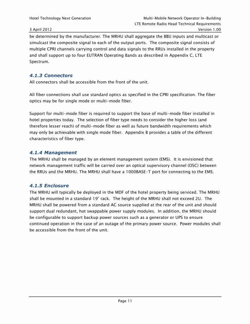
6.1 A. CPRI and 3GPP ORI specifications
CPRI Common Public Radio Interface (CPRI) Interface Specification v4.2 9-29-10
http://www.cpri.info/downloads/CPRI_v_4_2_2010-09-29.pdf
NOTE: ORI is still in ISG status (Industry Specification Group) under ETSI
ETSI ORI Specifications
http://portal.etsi.org/portal/server.pt/community/ORI/350
Open Radio Equipment Interface (ORI); ORI Interface Specification; Part 2: Control and
Management (Release 1)
Open Radio Equipment Interface (ORI); Open Radio equipment Interface (ORI) Requirements &
C&M update for Release 1 Release 1
The ETSI ORI Industry Specification Group
The interface which is being defined by the Industry Specification Group is an important step
towards realizing these benefits through widespread deployment of distributed Radio
Equipment for mobile communication networks.
The specification that the group is preparing covers those layers of the OSI stack required to
enable interoperability, and may refer to appropriate publicly available specifications. The
interface is built on top of an interface already defined by the CPRI (Common Public Radio
Interface) group. However, options are removed and functions are added with the objective of
making the interface fully interoperable.
Hotel Technology Next Generation Multi-Mobile Network Operator In-Building
LTE Remote Radio Head Technical Requirements
3 April 2012 Version 1.00
Page 19
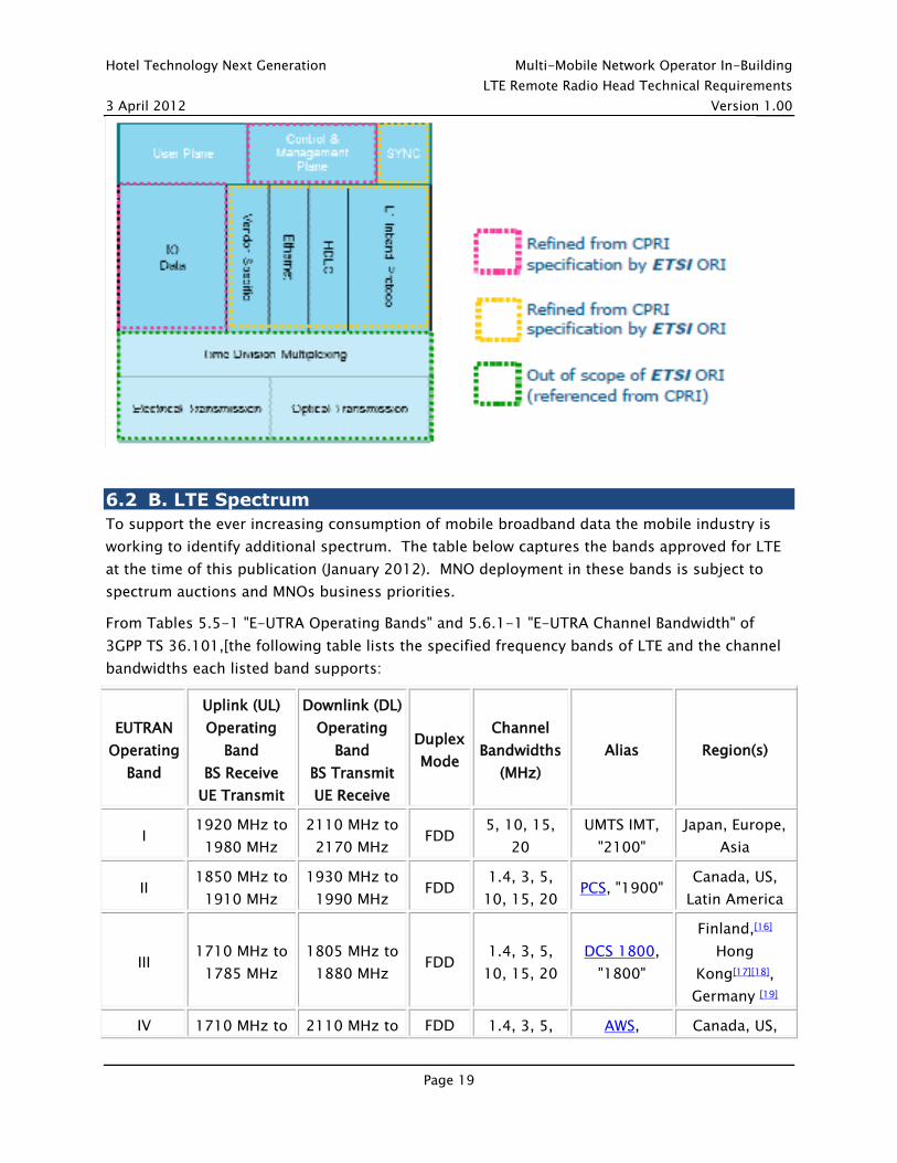
6.2 B. LTE Spectrum
To support the ever increasing consumption of mobile broadband data the mobile industry is
working to identify additional spectrum. The table below captures the bands approved for LTE
at the time of this publication (January 2012). MNO deployment in these bands is subject to
spectrum auctions and MNOs business priorities.
From Tables 5.5-1 "E-UTRA Operating Bands" and 5.6.1-1 "E-UTRA Channel Bandwidth" of
3GPP TS 36.101,[the following table lists the specified frequency bands of LTE and the channel
bandwidths each listed band supports:
EUTRAN
Operating
Band
Uplink (UL)
Operating
Band
BS Receive
UE Transmit
Downlink (DL)
Operating
Band
BS Transmit
UE Receive
Duplex
Mode
Channel
Bandwidths
(MHz)
Alias Region(s)
I 1920 MHz to
1980 MHz
2110 MHz to
2170 MHz FDD
5, 10, 15,
20
UMTS IMT,
"2100"
Japan, Europe,
Asia
II 1850 MHz to
1910 MHz
1930 MHz to
1990 MHz FDD
1.4, 3, 5,
10, 15, 20 PCS, "1900"
Canada, US,
Latin America
III 1710 MHz to
1785 MHz
1805 MHz to
1880 MHz FDD
1.4, 3, 5,
10, 15, 20
DCS 1800,
"1800"
Finland,[16]
Hong
Kong[17][18],
Germany [19]
IV 1710 MHz to 2110 MHz to FDD 1.4, 3, 5, AWS, Canada, US,

Hotel Technology Next Generation Multi-Mobile Network Operator In-Building
LTE Remote Radio Head Technical Requirements
3 April 2012 Version 1.00
Page 20
EUTRAN
Operating
Band
Uplink (UL)
Operating
Band
BS Receive
UE Transmit
Downlink (DL)
Operating
Band
BS Transmit
UE Receive
Duplex
Mode
Channel
Bandwidths
(MHz)
Alias Region(s)
1755 MHz 2155 MHz 10, 15, 20 "1.7/2.1
GHz"
Latin America
V 824 MHz to
849 MHz
869 MHz to
894 MHz FDD 1.4, 3, 5, 10
Cellular 850,
UMTS850
Canada, US,
Australia, Latin
America
VI 830 MHz to
840 MHz
875 MHz to
885 MHz FDD 5, 10 UMTS800 Japan
VII 2500 MHz to
2570 MHz
2620 MHz to
2690 MHz FDD
5, 10, 15,
20
IMT-E, "2.6
GHz"
EU, Latin
America
VIII 880 MHz to
915 MHz
925 MHz to
960 MHz FDD 1.4, 3, 5, 10
GSM,
UMTS900,
EGSM900
EU, Latin
America
IX
1749.9 MHz
to
1784.9 MHz
1844.9 MHz
to
1879.9 MHz
FDD 5, 10, 15,
20 UMTS1700 Japan
X 1710 MHz to
1770 MHz
2110 MHz to
2170 MHz FDD
5, 10, 15,
20
UMTS, IMT
2000
Uruguay,
Ecuador, Peru
XI
1427.9 MHz
to
1447.9 MHz
1475.9 MHz
to
1495.9 MHz
FDD 5, 10 PDC
Japan
(Softbank,
KDDI,
DoCoMo)[20]
XII 698 MHz to
716 MHz
728 MHz to
746 MHz FDD 1.4, 3, 5, 10
lower SMH
blocks A/B/C US
XIII 776 MHz to
787 MHz
746 MHz to
757 MHz FDD 5, 10
upper SMH
block C US
XIV 788 MHz to
798 MHz
758 MHz to
768 MHz FDD 5, 10
upper SMH
block D US
XVII 704 MHz to
716 MHz
734 MHz to
746 MHz FDD 5, 10 US
XVIII 815 MHz to
830 MHz
860 MHz to
875 MHz FDD 5, 10, 15
XIX 830 MHz to 875 MHz to FDD 5, 10, 15

Hotel Technology Next Generation Multi-Mobile Network Operator In-Building
LTE Remote Radio Head Technical Requirements
3 April 2012 Version 1.00
Page 21
EUTRAN
Operating
Band
Uplink (UL)
Operating
Band
BS Receive
UE Transmit
Downlink (DL)
Operating
Band
BS Transmit
UE Receive
Duplex
Mode
Channel
Bandwidths
(MHz)
Alias Region(s)
845 MHz 890 MHz
XX 791 MHz to
821 MHz
832 MHz to
862 MHz FDD
5, 10, 15,
20
EU's Digital
Dividend
800 MHz
EU
XXI
1447.9 MHz
to
1462.9 MHz
1495.9 MHz
to
1510.9 MHz
FDD 5, 10, 15
XXII 3410 MHz to
3490 MHz
3510 MHz to
3590 MHz FDD
5, 10, 15,
20
XXIII 2000 MHz to
2020 MHz
2180 MHz to
2200 MHz FDD 1.4, 3, 5, 10
XXIV
1626.5 MHz
to
1660.5 MHz
1525 MHz to
1559 MHz FDD 5, 10
XXV 1850 MHz to
1915 MHz
1930 MHz to
1995 MHz FDD
1.4, 3, 5,
10, 15, 20
XXXIII 1900 MHz to 1920 MHz TDD 5, 10, 15,
20
XXXIV 2010 MHz to 2025 MHz TDD 5, 10, 15
XXXV 1850 MHz to 1910 MHz TDD 1.4, 3, 5,
10, 15, 20
XXXVI 1930 MHz to 1990 MHz TDD 1.4, 3, 5,
10, 15, 20
XXXVII 1910 MHz to 1930 MHz TDD 5, 10, 15,
20
XXXVIII 2570 MHz to 2620 MHz TDD 5, 10, 15,
20 EU
XXXIX 1880 MHz to 1920 MHz TDD 5, 10, 15,
20
XL 2300 MHz to 2400 MHz TDD 5, 10, 15,
20 IMT-2000 China, India

Hotel Technology Next Generation Multi-Mobile Network Operator In-Building
LTE Remote Radio Head Technical Requirements
3 April 2012 Version 1.00
Page 22
EUTRAN
Operating
Band
Uplink (UL)
Operating
Band
BS Receive
UE Transmit
Downlink (DL)
Operating
Band
BS Transmit
UE Receive
Duplex
Mode
Channel
Bandwidths
(MHz)
Alias Region(s)
XLI 2496 MHz to 2690 MHz TDD 5, 10, 15,
20
XLII 3400 MHz to 3600 MHz TDD 5, 10, 15,
20
XLIII 3600 MHz to 3800 MHz TDD 5, 10, 15,
20
6.3 C. LTE Carrier Aggregation - Informative
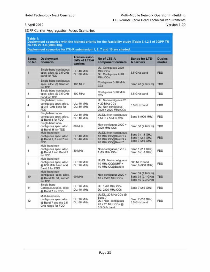
Carrier Aggregation (CA) is one of the most distinct features for LTE-Advanced systems, which
can support a much wider transmission bandwidth up to 100 MHz by aggregating two or more
individual component carriers belonging to the same (intra-band) or different (inter-band)
frequency bands. With CA, it is possible to schedule a device on multiple component carriers
simultaneously. From a radio resource management perspective, the component carrier’s
selection plays an important role in optimizing the system performance.
The following tables show the current focus and the overall prioritization respectively of the CA
scenarios.
Hotel Technology Next Generation Multi-Mobile Network Operator In-Building
LTE Remote Radio Head Technical Requirements
3 April 2012 Version 1.00
Page 23
3GPP Carrier Aggregation Focus Scenarios

Hotel Technology Next Generation Multi-Mobile Network Operator In-Building
LTE Remote Radio Head Technical Requirements
3 April 2012 Version 1.00
Page 24
6.4 D. LTE Terminal Categories
LTE Advanced / Release 10 added three new terminal categories highlighted in green below


