8
Cat. No. 1400Kg 75Kg 2012 - G/006 7,5kN E20 55R 01 D (kN) = MAX kg MAX kg MAX kg MAX kg x + x 0,00981 D = DACIA DOKKER E20

Cat. No.
1400Kg 75Kg
2012 -
G/006
7,5kN
E20 55R 01e20
D (kN) = MAX kg MAX kg
MAX kg MAX kg
x
+
x 0,00981
D =
DACIA DOKKER
E20

0Km 1000Km
Moment skręcający dla śrub i nakrętek (8.8) Torgue settings for nuts and bolts (8.8)
M8
M10
M12
M14
M16
25Nm
55Nm
85Nm
135Nm
195Nm
R 14,5 max.
30o max.
30o max.
R40 max.
75 m
in.
75 m
in.
AA
100 max.
140
min
.
PRZEKRÓJ A-A
55 m
in.
32 m
in.
350-
420
PL Należy zagwarantować przestrzeńswobodną według załącznika VII,rysunek 25a/b Regulaminu EKGONZ 55.01 przy dopuszczalnym ciężarze całkowitym pojazdu.
L’espace libre doit etre garanticonformement a l’annexe VII,illustration de la reglements 55.01 CE pour un poids total en charge autorise du vehicule.
The clearance specified in appendix VII, diagram 25a/b of Regulation No.55.01 UN EU must be guaranteed atladen weight of the vehicle.
Der Freiraum nach Anhang VII, Abbildung 25a/b der Vorschriften 55.01 EG ist zu gew 25a/b ahrleistenbei zulassigem Gesamtgewichtdes Fahrzeuges.
GB
F
D

x1
x1
x1
x1
x1
x1
M12x70 2M12x35M10x110M6x25 2M12 6M10M6 2
Ø30xØ10,5x3 8
Ø18xØ6,5x1,5
13 6
13 610,56,5 2

B
Pkt. 2
Pkt. 1
Śrub
a M12
x35-
8.8 ;
Bolt
Pkt. 3
Śrub
a M12
x70-
8.8 ;
Bolt
Nakrę
tka M
12 ; N
utPo
dkł. s
pręż
.12,2
; Spr
ing W
ashe
rPo
dkł. o
kr. 13
; Plai
n Was
her
Nakrę
tka M
12 ; N
utPo
dkł. s
pręż
.12,2
; Spr
ing W
ashe
rPo
dkł. o
kr. 13
; Plai
n Was
her
Śrub
a M10
x110
-8.8
; Bolt
Podk
ł. okr.
Ø30
x Ø10
,5x 3
; Plai
n Was
her
Śrub
a M10
x110
-8.8
; Bolt
Podk
ł. okr.
Ø30
x Ø10
,5x 3
; Plai
n Was
her
Nakrę
tka M
10 ; N
utPo
dkł. s
pręż
.10,2
; Spr
ing W
ashe
rPo
dkł. o
kr. Ø
30x Ø
10,5x
3 ; P
lain W
ashe
r
Nakrę
tka M
10 ; N
utPo
dkł. s
pręż
.10,2
; Spr
ing W
ashe
rPo
dkł. o
kr. Ø
30x Ø
10,5x
3 ; P
lain W
ashe
r
Nakrę
tka M
12 ; N
utPo
dkł. s
pręż
.12,2
; Spr
ing W
ashe
rPo
dkł. o
kr. 13
; Plai
n Was
her
Śrub
a M 6x
25-8
.8 ; B
oltPo
dkł. o
kr. Ø
18x Ø
6,5x 1
,5 ; P
lain W
ashe
rNa
krętka
M6 ;
NutŚr
uba M
12x3
5-8.8
; Bo
lt
Pkt. 3
Pkt. 1
Pkt. 2
Nr ka
talog
owy
Marka
96-1
11 K
owie
sy, C
hojn
ata
23 A
tel.
+48
46 8
31 7
3 31

• Placer les douilles d'écartement dans les ouvertures de longerons,• Visser les éléments d'attache C aux longerons par les boulons M10x110, 8.8 (point 1, 2),• Visser les éléments C,D à la traverse d'attache A par les boulons M12x35 8.8 (point 3),• Serrer tous les boulons avec un couple de serrage selon tableau,• Visser le crochet d'attelage et socle de prise électrique,• Raccorder le circuit électrique.
• Odkręcić tylne nadkola.• Zdemontować lewą osłonę termiczną przy zderzaku.• Odkręcić zderzak i lampy.• Wypełnienie zderzaka usunąć (nie będzie już potrzebne).• Udrożnić technologiczne otwory w podłużnicach.• Tulejki włożyć w otwory w podłużnicach.• Następnie elementy C i D przykręcić lekko śrubami M10x110 8.8 (pkt 1,2) z elementami F.• Belkę haka A wsunąć między elementy i przykręcić śrubami M12x40 8.8 (pkt 3).• Zamontować lampy, zderzak, osłonę termiczną oraz nadkola.• Zderzak od spodu przykręcić śrubami M6x25.• Dokręcić wszystkie śruby z momentem według tabeli.• Dokręcić kulę i blachę gniazda elektrycznego.• Podłączyć instalację elektryczną.
• Unscrew the rear wheel arches.• Dismount the left thermal shield near the bumper.• Unscrew the bumper and lamps.• Remove the �lling of the bumper (it will not be used anymore).• The technological holes in the frame side members make permeable.• Insert the sleeves in the holes of the frame side members.• Screw slightly the elements C and D to the elements F with bolts M10x110 8.8 (point 1, 2).• Insert the main bar A between the elements and screw with bolts M12x40 8.8 (point 3).• Assemble the lamps, bumper, thermal shield and rear wheel arches.• Screw the bumper with bolts M6x25.• Tighten all the bolts according to the torque setting- see the table.• Fix the ball and electric plate.• Connect the electric wires.

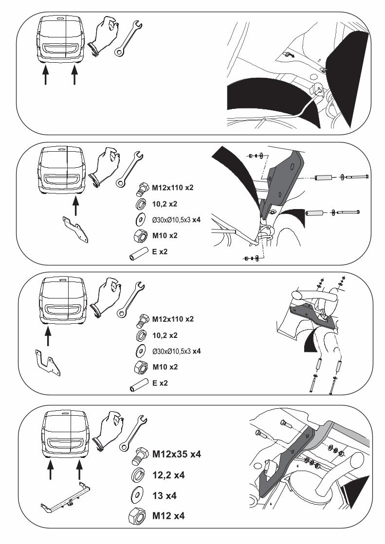
M12x110 x2
10,2 x2
Ø30xØ10,5x3 x4
M10 x2
E x2
M12x110 x2
10,2 x2
Ø30xØ10,5x3 x4
M10 x2
E x2
M12x35 x4
12,2 x4
13 x4
M12 x4
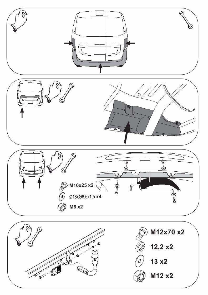
M12x70 x2
12,2 x2
13 x2
M12 x2
M16x25 x2
Ø18xØ6,5x1,5 x4
M6 x2


