161
Installation and Operation User Guide Marine Satellite Communication Antenna System v240C

Installation and Operation User Guide
Marine Satellite Communication Antenna System
v240C


Serial number of the product
This serial number will be required for the all troubleshooting or service inquiries.
© 2012 Intellian Technologies, Inc. All rights reserved. Intellian and the Intellian
logo are trademarks of Intellian Technologies, Inc., registered in the U.S. and other
countries. The v-Series and the v240C are trademarks of Intellian Technologies,
Inc. Intellian may have patents, patent applications, trademarks, copyrights,
or other intellectual property rights covering subject matter in this document.
Except as expressly provided in any written license agreement from Intellian,
the furnishing of this document does not give you any license to these patents,
trademarks, copyrights, or other intellectual property.
All other logos, trademarks, and registered trademarks are the property of their
respective owners. Information in this document is subject to change without
notice.
Every effort has been made to ensure that the information in this manual is
accurate. Intellian is not responsible for printing or clerical errors.
Doc. No. 2012 R0-UM0529-V2

INDEX

5
INDEX
INTRODUCTION
Introduction to Intellian v240C 7
Features of Intellian v240C 8
Basic System Configurations 9
INSTALLING THE ANTENNA
System Components 11
Planning the Installation 18
Antenna Installation 21
INSTALLING THE ACU
Mounting the ACU 54
Ship Gyro Connection 56
WiFi and Bluetooth Connection 58
ACU Connector Guide 59
OPERATING THE ACU
Introduction 62
Normal Mode 64
Setup Mode 68
Installation Settings 69
Antenna Settings 72
Satellite Settings 84
System Settings 91
PC CONTROLLER SOFTWARE
Introduction 100
PC to ACU Communication Setup 101
Main Menu 103
Controller Menus 105
REMOTE WEB ACCESS
Introduction 112
Main Page 113
Antenna Settings 115
Antenna / ACU Firmware Upgrade 131
Ethernet to Serial Settings 137
WARRANTY 150
APPENDIX
Java Download and Install Guide 151
Setup WiFi Connection 155
TECHNICAL SPECIFICATION 160

v240C – Marine Satellite Communication System
6
Introduction to Intellian v240C
Features of Intellian v240C
Basic System Configurations
INTRODUCTION

7
INTRODUCTION
Introduction to Intellian v240C
The Intellian v240C is a 2.4 meter C-band marine VSAT communication antenna system. With its 3-axis stabilized platform and enhanced vibration and shock damping design, the v240C can perform extremely well on all types of ships that require “always on” and “high speed” broadband communications no matter how rough the weather and sea conditions are.
The v240C requires minimal involvement to commission . It is easy to operate and also simple to upgrade and manage. Each unit comes preloaded with a ready-to-use, client-customized library that can be conveniently tailored further via PC software (also included with the unit), and firmware updates can be done entirely through the Wi-Fi ACU. Wi-Fi router enables easy connection and control of ACU, allowing operators to check the status of the VSAT.
The all new Antenna Control Unit (ACU) supports Wi-Fi connectivity for a simple remote PC connection. If the ACU is installed at a great distance from the antenna, then the built-in Bluetooth connection module can enable a PC connection right alongside the dome.
Robust and versatile, the v240C marks an new era for VSAT connectivity on the open water for deep sea vessels that require global coverage.

v240C – Marine Satellite Communication System
8
Features of Intellian v240C
Automatic Polarization SwitchingIntellian v240C antenna automatically changes between linear and circular polarization while it does not require manual or physical change. When a polarization is selected from ACU or PC Control Program, the Feed Horn is automatically adjusted accordingly, which is patented technology developed by Intellian.
DVB/DVB-S2 and NBD detection capability Intellian v240C is capable of detecting DVB-S/DVB-S2 signal, SCPC, and Narrow-Band signal. Thanks to its integrated digital tuner and the narrow band detector (NBD).
Wireless communication with the ACUThe ACU of the Intellian v240C offers upgraded functions. The built-in Wi-Fi wireless network card enables the ACU to be wirelessly connected, and it can be either turned on and off by a switch. After connecting with Wi-Fi wireless network or setting up a network with ACU, it will be easy to monitor, control, and change the settings of Intellian antenna system wirelessly using laptops, smartphones, or any kind of wireless devices.
Antenna log data and firmware upgrade through USBThe ACU of v240C now automatically stores all action data of Intellian antennas onto a built-in 256MB memory. With 256MB memory, about one month of data can be stored, and all existing logs are available to be transferred onto USB drivers. Also just by plugging in the USB with firmware update files stored, the firmware can be automatically updated and upgraded onto the ACU.
Bluetooth module supportWhen the Intellian supplied Bluetooth module is equipped on a main control unit of Intellian antenna, users can access and control the antenna with a laptop that has Bluetooth capability. This will lead to easier and more effective ways to setup and maintain the system.
Maximized RF performanceThe main reflector, Feed-horn and other RF parts are newly designed to maximize the antenna performance for maritime application. Not only the gain and Maximum Allowed EIRP Density are the highest level amongst the similar-sized VSAT antenna, Intellian v240C conforms to various ESV (Earth-Station-on Vessels) standards and FCC requirements.

9
INTRODUCTION
Basic System Configurations
For your satellite VSAT system to work properly, the system will have to be connected with all of the provided components properly as shown in the figure below (Refer to next chapter ‘Installation’ in this manual for more detailed connection instructions).
Basic System Configuration
AntennaControl Unit
Modem InterfaceModem RX
SatelliteModem
90-260V AC
*Modem is not supplied
Modem TX Antenna RX

v240C – Marine Satellite Communication System
10
INSTALLINg ThE ANTENNA
System Components Antenna Unit ACU (Antenna Control Unit) Installation Kit
Planning the InstallationSelection of Antenna Installation Site Configure Radiation Hazard/Blockage Zones System Cables Power Requirement Tools Required for Installation
Antenna InstallationUnpacking the Wooden Crate Antenna DimensionsAntenna Mounting TemplatesPosition the Radome Open the Radome HatchMount the RadomeRF Cable ConnectionsSecure the RF Cables
11
INSTALLING THE ANTENNA
System Components
Antenna unit
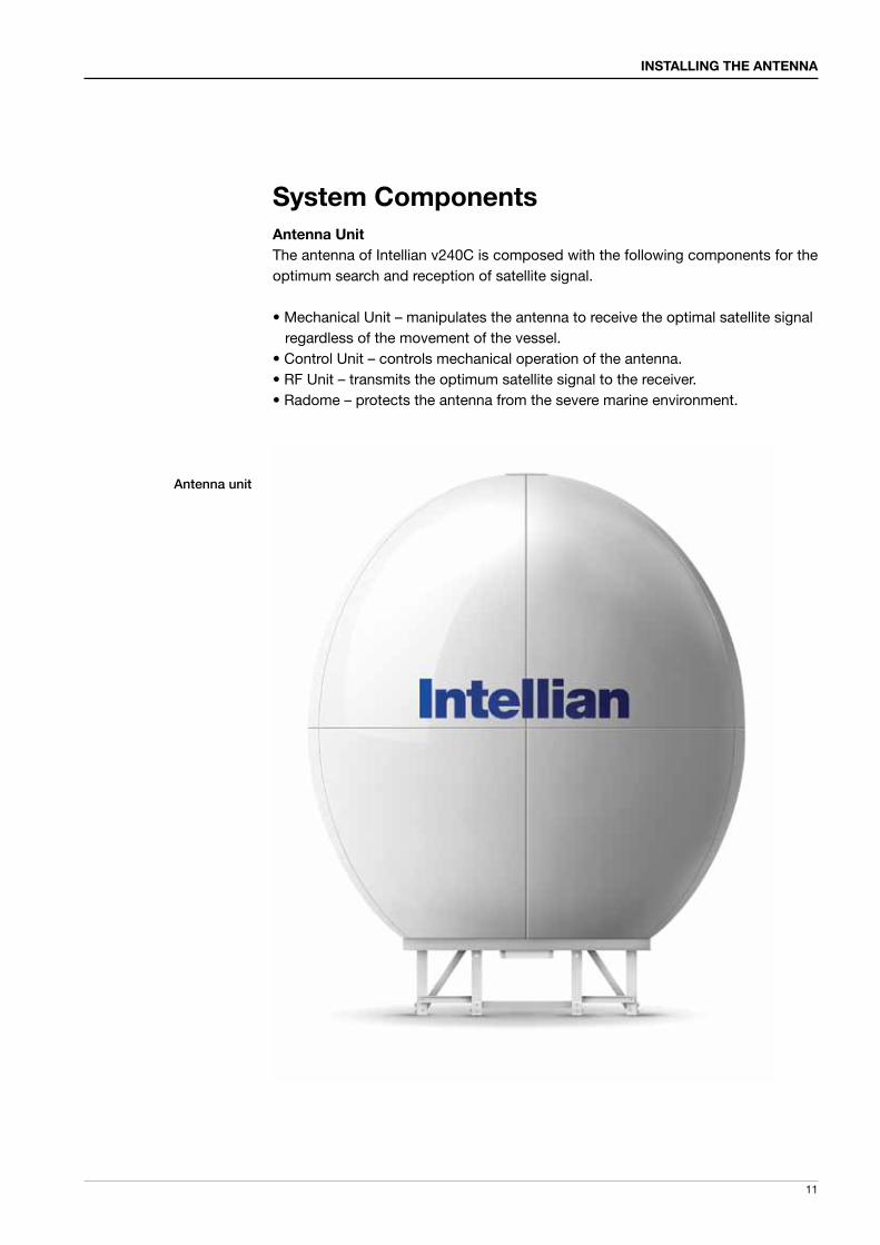
Antenna UnitThe antenna of Intellian v240C is composed with the following components for the optimum search and reception of satellite signal.
• Mechanical Unit – manipulates the antenna to receive the optimal satellite signal regardless of the movement of the vessel. • Control Unit – controls mechanical operation of the antenna.• RF Unit – transmits the optimum satellite signal to the receiver.• Radome – protects the antenna from the severe marine environment.

v240C – Marine Satellite Communication System
12
ACU (Antenna Control Unit)The Antenna Control Unit (ACU) provides the power to the antenna and controls the various settings of the antenna.
Antenna Control Unit
The functions of the ACU are as follows: • Provide power for the antenna unit• Monitor the antenna status• Change the target satellite • Set up the user environment• Set the current GPS information • Set satellite information• Move antenna manually• Built-in real-time diagnostics function and event log recorder• Set up the interface with a PC• Supports Wi-Fi & Bluetooth ACU operation• Log data and firmware upgrade through USB• Built-in web-based remote control management

13
INSTALLING THE ANTENNA
Installation KitContains the items required for securing the antenna unit and ACU to the vessel.
Antenna Q’ty Description Size Remark
4 Hex Bolt M16x40L
Stable Mount4 Flat Washer M16
4 Spring Washer M16
9 Hex Bolt M12x65
Post17 Flat Washer M12
9 Spring Washer M12
17 Nut M12
235 Hex Bolt M6x25L
Radome
55 Hex Bolt M6x30L
535 Flat Washer M6 (Ø18)
270 Spring Washer M6
270 Nut M6
9 Hex Bolt M12x60L
Antenna Deck17 Flat Washer M12
9 Spring Washer M12
17 Nut M12
ACU Q’ty Description Size Remark
5 Self-Tapping Screw
ø 4 x 16Table Mount
Bracket
10 Flat Head Screw M3 x 8LRack Mount Bracket ACU
5 Sems Bolt M3 x 12LTable Mount Bracket ACU

v240C – Marine Satellite Communication System
14
Image Q’ty Description Size Remark
1
2
ACU Bracket
Rack - ACU-19inch Rack
2 Table - ACU-Table
2 2 RG6 Cable 3mACU toModem
3 2 RG6 Cable 30mANT to ACU,
ANT to Modem
4 1AC Power Cord
(CEE 7/7)1.5m ACU Power
5 1AC Power Cord
(USA)1.8m ACU Power
6 1 PC Serial Cable 1.8m ACU to PC
7 1USB Cable
(A-A)1.8m ACU to PC
8 1iDirect Interface
Cable1.5m ACU to Modem
9 1D-Sub 9pin Male
Connector- ACU
10 3 N to F Adapter -N (Male) to F (Female)
Adapter
Other Components

15
INSTALLING THE ANTENNA
11 1 Manual - -
12 1
iDirect Modem Cable Pin
Connection Manual
- -
13 1 USB Flash Drive - -

v240C – Marine Satellite Communication System
16
Tools required for Installation

17
INSTALLING THE ANTENNA
Box Adaptor
Silicon Silicon gun
10/19/24mm box socket
Ratchet handle Monkey spanner
Long socket Impact drill

v240C – Marine Satellite Communication System
18
Planning the InstallationSelection of Antenna Installation SiteThe installation of v240C requires extreme precaution and safety measures given its size and weight. Failure to follow the correct installation process may lead to injury to the installer and/or cause damage to the system.
In order to maximize the performance of the system, a thorough review of this installation guide is strongly recommended, as well as executing the installation process as it is noted on this manual.
The system should be placed where there would be no blockage that would interfere the signals. A safe mounting place should be selected for given its heavy weight and size.
• System Cables Before installing the system cables, you need to take the following points
into consideration. 1. All cables need to be well clamped and protected from physical damage and
exposure to heat and humidity. 2. Remember to observe the minimum bend radius of the selected cable. 3. Where a cable passes through an exposed bulkhead or deck-head, a watertight
gland or swan neck tube should be used.

19
INSTALLING THE ANTENNA
• Power RequirementsYou need to follow the power requirements to avoid damage the system.Intellian v240C is designed to work on a power supply between 90-260V AC.
• Extending the CablesThe cables that have been supplied with your Intellian system should be of adequate length to complete the installation on most boats.
• Power Cable This cable supplied at a length of 10m.
• RF Cable This cable is supplied at a length of 30m. If a longer length is required you should replace this cable with an extended RF cable supplied by Intellian Technologies.
NOTE: Exceeding the indicted cable lengths will result in reduced performance of your system.

v240C – Marine Satellite Communication System
20
Installation and mounting of antennaThe method of installation and mounting of antenna may vary with vessel design but the following procedures are applicable in most situations, and will result in a secure and effective installation.
Confirmation of size prior to installation• Confirm the height and diameter of the bottom surface of the antenna before installing it.• The space must be sufficient for installing the antenna unit considering the height and diameter of the antenna.• The height and the diameter of the bottom surface of the antenna are as shown in the following drawing. It is strongly suggested that the installation is conducted using a crane.
�1900
305
3517
.3
3822
.3
�3300
Antenna Dimensions

21
INSTALLING THE ANTENNA
Antenna InstallationDismantling the antenna packaging (Packing is subject to change)Upon the arrival of the antenna package, the following instruction needs to be followed in order to execute the proper removal of the system from its original packaging.
To secure the safe installation process, please make sure to have enough space (10m x 10m x 10m) around the unit
A: 2300mm, B:2220mm, C:2700mm, D:3000mm, E:2220mm, F: 2300mm
1. Secure enough space for un-packaging procedures
A
D
E
F
B
C

v240C – Marine Satellite Communication System
22
2. Dismantling the Radome Package
On the picture shown on left, boxed-side of wooden assembly needs to be dismantled. There are nails on the circled parts of the packaging.
The packaging will be taken apart using an Impact Drill.
The packaging will be taken apart using an Impact Drill.
A.
B.
C.

23
INSTALLING THE ANTENNA
Remove the wall as shown left.
D.

v240C – Marine Satellite Communication System
24
3. Dismantling The Radome panels
Cut all the ties around the radome panels.
Carefully remove the radome panels.
After complete removal of radome panels, packaging should be as shown left.
A.
B.
C.

25
INSTALLING THE ANTENNA
After complete removal of the wooden bar in section A directly above, the packaging should be seen as shown left.
Now prepare to remove the Base frame by removing M6 Hex bolts from wooden crate floor and base frame legs.
B.
C.
4. Removal of Radome Panel Supports and Base Frame
Remove the wooden bar that supported radome panels using an Impact Drill.
A.

v240C – Marine Satellite Communication System
26
5. Attach buckles to the Base Frame
Now prepare to attach buckles to base frame in order to lift the base frame from wooden crate.
As shown left, all buckle ropes should be applied to all 4 joints of the base frame.
After applying buckle ropes to all 4 corners, attach lifting strap to buckle ropes.
A.
B.
C.
27
INSTALLING THE ANTENNA
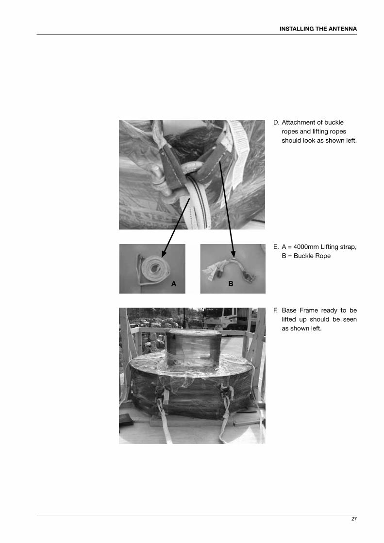
Attachment of buckle ropes and lifting ropes should look as shown left.
A = 4000mm Lifting strap, B = Buckle Rope
Base Frame ready to be lifted up should be seen as shown left.
D.
E.
F.
A B

v240C – Marine Satellite Communication System
28
6. Dismantle Radome Base Frame
Now prepare to attach buckles to base frame in order to lift the base frame from wooden crate.
Secure the strap tightly as shown left for a safe removal.
Make sure that the center of Base Frame is located right below of hook of Crane to create a good center of gravity and perform safe removal of base frame.
A.
B.
C.

29
INSTALLING THE ANTENNA
Very slowly lift up the base frame and watch as the base frame lifts up to prevent big interference with wooden crate.
Lower the base frame onto the floor and remove the lifting assembly.
D.
E.

v240C – Marine Satellite Communication System
30
Dismantle the wooden assembly of the antenna package using an impact drill.
Remove the vinyl layer from the antenna.
Under the wooden support, there is a post laying. Remove the post by sliding it out, then cut the ties or tapes around the post.
A.
B.
C.
7. Dismantle the Antenna Package and Free the CL Arm

31
INSTALLING THE ANTENNA
Locate the 2 brackets on the rear of the CL Arm.
Take out all brackets on the rear of the CL Arm by removing M6 Hex bolts with an impact drill.
D.
E.

v240C – Marine Satellite Communication System
32
Locate the 2 M12 Hex bolts on each side of the EL Arm. They are connected to the EL Arms.
Remove the 2 M12 Hex Bolts securing each side of the EL Arm.
Remove the 2 M12 Hex Bolts securing each side of the EL Arm.
A.
B.
C.
8. Remove Bolts on EL Arm

33
INSTALLING THE ANTENNA
Locate the M16 bolts that secure the pedestal assembly to the crate.
Remove the M16 Hex Bolts and Nuts using a wrench as shown left
A.
B.
9. Free the Upper Antenna

v240C – Marine Satellite Communication System
34
With the direction of the bow in mind, place the post on the top of the base frame.
Check to confirm the orientation of the pedestal support with regards to the bow.
A.
B.
10. Assembly of Base Frame and Post

35
INSTALLING THE ANTENNA
Secure the lower pedestal to the base frame with the 8 M12 x 65 bolts supplied. Lock the bolts by installing double nuts onto the bolts. Make sure to apply Loctite 262 to the bolts to securely tighten the assembly.
Now for the final time, please make sure that the post is attached in accordance with correct bow direction. Power switch unit mount plate should be on the right side when looking from stern to bow of the base assembly.
D.
E.
Please note the bow direction as shown left.
C.
BOW Direction
Power Switch UnitMount Plate

v240C – Marine Satellite Communication System
36
In order to attach lifting straps, the following steps must be performed.
This is the initial position of the EL Arm fixture bolt.
The initial position should be moved to the middle tap as indicated on left.
A.
B.
C.
11. Lifting the Upper Antenna
37
INSTALLING THE ANTENNA
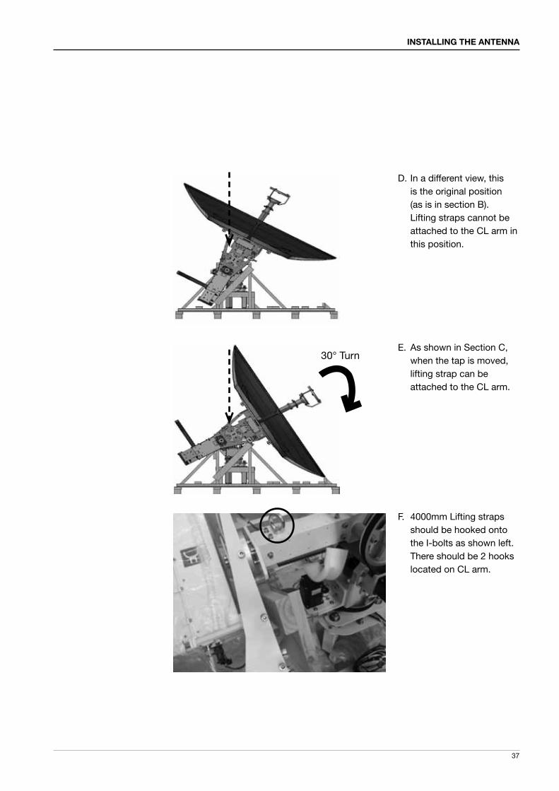
In a different view, this is the original position (as is in section B). Lifting straps cannot be attached to the CL arm in this position.
As shown in Section C, when the tap is moved, lifting strap can be attached to the CL arm.
4000mm Lifting straps should be hooked onto the I-bolts as shown left. There should be 2 hooks located on CL arm.
D.
E.
F.
30° Turn

v240C – Marine Satellite Communication System
38
Securely hook the lifting straps as shown. (On the both side of the CL arm)
Securely hook the lifting straps as shown. (On the both sides of the CL arm)
G.
H.

39
INSTALLING THE ANTENNA
Hook the straps to the crane and slowly lift up the system as shown.
Do not place the antenna onto the post just yet. Follow the next steps in section 12, Securing Cables.
I.

v240C – Marine Satellite Communication System
40
Locate the power and RF cables as shown.
Pull the cables through the center of the pedestal middle plate as shown on left.
The cables need to be inserted through the center of the pedestal support as indicated
A.
B.
C.
12. Securing Cables

41
INSTALLING THE ANTENNA
Place the cables through the center hole of the Post as shown in C.
Cables should come out of the bottom of the post as shown left.
D.
E.

v240C – Marine Satellite Communication System
42
13. Assembly of Upper Antenna and Post
Locate the power and RF cables as shown.
Insert the 3 M16 x 40 bolts to secure the antenna assembly to the pedestal. Make sure to apply Loctite 262 to securely tighten the assembly.
The system should be mounted so the AZ sensor is on the stern position of the base assembly.
A.
B.
C.
BOW Direction
BOW Direction
BOW Direction

43
INSTALLING THE ANTENNA
14. Assemble Lower Radome panels and Base Frame
Now assemble the lower radome panels. M6x25L bolts are used for the connection between panels, and M6x30L bolts are used for connection between panels and base frame.
NOTE: Bow Direction should be the opposite of Hatch.
Apply silicon (Sikaflex-291) to side of radome panels before applying bolts.
A.
B.
C.
M6x25L
M6x30L

v240C – Marine Satellite Communication System
44
Apply the bolts as shown left with corresponding sizes
Make sure to apply bolt and nut as shown. It is recommended that the max torque be 15Nm.
D.
E.

45
INSTALLING THE ANTENNA
Assemble 5 radome panels as indicated in previous section.
Make sure to tighten all the joints before proceeding to next step. Plus, make sure to clean out the silicon mess to give a smooth finish
Direction of the hatch should be the exactly opposite of Bow direction.
A.
B.
C.
15. Assembly of Lower Radome
BOW
Hatch Direction

v240C – Marine Satellite Communication System
46
Apply the silicon between the radome panels from the outside.
Make sure to clean out the silicon for smooth finish
Finished lower radome should look as shown.
A.
B.
C.
16. Applying Silicon to Lower Radome Panels

47
INSTALLING THE ANTENNA
17. Assembly of Upper Radome Cap and Finishing
Assemble 4 upper radome panels as shown left.
You are now ready to install the radome cap.
Fix the cap in place with a layer of silicon and loosely fasten the M6 bolts but do not tighten them at this time.
A.
B.
C.

v240C – Marine Satellite Communication System
48
18. Assembly of Upper Radome Panels
The assembly of the upper radome panels should now be completed, using theM6 x 25 bolts supplied.
Apply silicon (Sikaflex-291) to side of radome panels before fastening bolts.
Make sure to apply bolt and nut as shown. It is recommended that the max torque be 15Nm.
A.
B.
C.

49
INSTALLING THE ANTENNA
After the attachment of the cap, the last panel of the radome should be installed to finish the assembly. The final section is completed with a person inside the radome so a provision needs to be made so they can be released by lifting the completed dome. At this point all bolts should be tightened. Any excess silicon should be removed to give a clean finish.
D.

v240C – Marine Satellite Communication System
50
19. Applying Silicon to Upper Radome Panels
Apply the silicon from the outside between the radome panels.
Remove excess sealant and smooth to complete the radome top section.
A.
B.

51
INSTALLING THE ANTENNA
20. Final Assembly of Radome
There are 4 sets of M6x25 Hex Bolts and Nuts that should be applied to 4 locations of the upper radome. The assembly shown on left should be constructed on each of 4 locations.
Connect the lifting strap to the radome.
Radome should be lifted up slowly as shown by a crane.
A.
B.
C.

v240C – Marine Satellite Communication System
52
Apply silicon to the top lip of the lower section of the radome then slowly place the upper radome on to the lower radome half. Slowly place the upper radome on top of the lower radome assembly.
Once placed onto the lower half fasten with the supplied nuts and bolts. Then clean off any excess silicon.
D.
E.
Enter the radome hatch and take out 2 brackets under the CL Arm.Remove the M6 Hex bolts to free the CL Arm.
F.
WARNING: Never operate the antenna before installation is complete. Doing so may damage the antenna system including motor control.

INSTALLINg ThE ACU
Mounting the ACU19” Rack Mount Type
Table Mount Type
ACU Dimensions
Selection of ACU Installation Site
Ship Gyro ConnectionConnecting the System with a Ship’s Gyro
Connecting the System without a Ship’s Gyro
WiFi & Bluetooth Connection
ACU Connector Guide

v240C – Marine Satellite Communication System
54
Mounting the ACU
Intellian supplies two types of mounting methods (a) 19” Rack Mount Type and (b)Table Mount Type to mount your ACU.
19” Rack Mount Type- The ACU should be installed using the two supplied Rack Mounting Brackets
which allow for a side 19” rack mounting configuration.- Using the self tapping screws supplied, attach the mounting brackets to the sides
of the ACU.- Place the ACU in the location where it is going to be installed.- Connect the cables to the rear of the ACU.
Table Mount Type- The ACU should be installed using the two supplied Table Mounting Brackets
which allow for a top or bottom mounting configuration.- Using the self tapping screws supplied, attach the mounting brackets to the sides
of the ACU.- Place the ACU in the location where it is going to be installed.- Using a pencil to mark the 4 hole positions (2 on each side), and use the appropriate
drill bit to screw down the brackets.- Connect the cables to the rear of the ACU.
WARNING: Ensure that the cables connected to the ACU are long enough to prevent damage when the ACU is pulled out from the rack.
19" Rack Mount Type
Table Mount Type

55
INSTALLING THE ACU
Selection of ACU Installation Site
The ACU should be installed below deck, in a location that is:• Dry, cool, and ventilated.• The front panel should be easily accessible to the user.
ACU Dimensions
Dimension of ACU

v240C – Marine Satellite Communication System
56
Ship Gyro ConnectionConnecting the System with a Ship’s Gyrocompass
For satellite tracking, you must connect a ship’s Gyro to the antenna system through the gyro interface on the rear of the ACU. Intellian’s ACU supports NMEA 0183 and NMEA 2000 gyro types. If the ship’s gyrocompass output uses something different than a NMEA 0183 or NMEA 2000, a separate purchase of a gyro converter is required.
• NMEA 0183 Gyro Compass Interface Cable (Customer Supplied)• Type: 2 conductors for NMEA 0183• NMEA heading sentence: xx HDT (4800 Baud, 8, N,1)
If there is no HDT sentence then use HDM sentence instead.• NMEA 2000 heading PGN Number = 127250 (Vessel Heading)
Strip the cable for 5 mm (0.2")Do not solder the cable

57
INSTALLING THE ACU
Connecting the System without a Ship’s Gyrocompass
For a vessel where the ship’s gyrocompass is not installed or is difficult to connect, the Intellian Gyro-Free satellite search function will be automatically enabled to allow the antenna to lock onto the desired satellite without requiring an external heading input.
The table below provides an example of the Gyro-Free satellite search algorithm. The Search 1 or Search 3 satellite search pattern will be triggered according to the existence of heading input and the setting of the heading device.
Search 1: The antenna will search for the target satellite by turning its azimuth angle in a CCW(Counter Clockwise) direction until the antenna receives a lock signal from the modem or until the DVB(Digital Video Broadcasting) transponder of the target satellite is decoded by the antenna.
Search 3: The antenna will search for the target satellite by turning its azimuth angle directly to the position calculated using the ship’s heading input and lock onto the satellite.
Quick Setup Procedure• Set the satellite having DVB transponder as the target satellite.• Set “No Device” to the heading device.• The antenna will search for the target satellite by turning its azimuth angle in
a CCW direction and lock onto the satellite signal until the antenna receives a lock signal from the modem or until the DVB transponder of the target satellite is decoded.
• Set the heading device as NMEA - Enter the “Manual search” menu and press the “Function” key to save the current settings. Intellian's ACU will automatically calculate and save the BOW offset. - Upload the real TARGET satellite pre-configured from the library.
Setting of Heading Device
Existence of Heading Data No Device NMEA / NMEA 2000 Ground Test
w/ Heading Data Search 1 Search 3 Search 3
w/out Heading Data Search 1 Search 1 Search 3

v240C – Marine Satellite Communication System
58
Wi-Fi and Bluetooth Connection
Connect to the ACU via Wi-Fi and antenna via Bluetooth for complete control and monitoring whenever you are on a vessel. Refer to the appendix section to setup your Bluetooth/WiFi usage on page 131 and page 138, respectively.
WiFi On/Off Switch

59
INSTALLING THE ACU
123456789
543219876
ACU Connector Guide
• Console Port
NOTE: NMEA GPS IN/OUT Sentence: GPGLL (4800 Baud, 8, N, 1)
Pin Signal Pin Signal
1 GND 6 GPS OUT -
2 GPS OUT + 7 MODEM_SIGNAL_IN
3 MODEM_LOCK 8 MODEM_CTRL2
4 MODEM_CTRL1 (TX MUTE) 9 GPS IN -
5 GPS IN +
ACU Console PortD-Sub 9 pin Female
D-Sub 9 pin Male connectorSupplied Component
123456789
123456789
Pin Signal Pin Signal
1 - 6 -
2 RXD 7 -
3 TXD 8 -
4 - 9 -
5 GND
Pin Signal Pin Signal
1 - 6 -
2 RXD + 7 RXD -
3 TXD + 8 TXD -
4 - 9 -
5 GND
D-Sub 9 pin RS232 Connector
D-Sub 9 pin RS422 Connector
• RS232 / 422 Connector (Modem & BUC Interface)

v240C – Marine Satellite Communication System
60
• NMEA 2000 Connector
5
43
2 1 Pins
Connector Threads
5
43
2 1 Sockets
Connector Threads
Pin Signal
1 Shield
2 NET-S, (power supply positive, +V)
3 NET-C, (power supply common, -V)
4 NET-H, (CAN-H)
5 NET-L, (CAN-L)
Pin Signal
1 Shield
2 NET-S, (power supply positive, +V)
3 NET-C, (power supply common, -V)
4 NET-H, (CAN-H)
5 NET-L, (CAN-L)
Male Connector Female Connector

OPERATINg ThE ACUOPERATINg ThE ACU
Introduction
Normal Mode
Setup Mode
Installation Settings
Antenna SettingsManual SearchSetup Antenna LNB pol Angle Search ParametersSetup Antenna Parameters Setup Block ZoneAntenna Diagnostic Test
Satellite SettingsLoad SatelliteEdit Satellite InformationAdd Satellite InformationCheck NID
System SettingsSet LNB Local Oscillator FrequencySet LocationSet Modem PortSystem Backup & RestoreDisplay Versions

v240C – Marine Satellite Communication System
62
This section of the handbook describes how to setup your system after installing the ACU. It includes the following functions:
Introduction
• System start up.• Changing the default satellite.• Monitoring the antenna status.• Setting sleep mode. • Entering setup mode.• Setting the satellite pair.• Editing satellite information.• Setting the antenna parameter. • Setting the LNB local frequency.• Setting GPS.• Setting the DiSEqC method.• Display versions.• Display power status.• Setting antenna go position.• Setting antenna move step.• Setting remote control. • Setting the factory default parameters.• Performing diagnostic tests.
NOTE: Many of the above functions will only be required only after initial installation of your system. Refer to the Quick Installation Guide before operating the system.

63
OPERATING THE ACU
ACU Soft Keys
Soft key Function
MODE Enter SETUP mode
RETURN In SETUP mode: return to previous menu / option or save the adjusted settings. In normal mode: return to the first page of antenna current status.
FUNCTION Save the adjusted settings.
ARROW KEYS Select from the alternative options to increse or decrese the selected character to the desired value.
OK Enter next step / menu
NUMBER KEYS Input the numbers
Soft Key Functions
Return Function NumberKeys
Mode Arrow Keys
INITIALIZE - ANTENNA INFO
INTELLIAN v240

v240C – Marine Satellite Communication System
64
INTELLIAN TECHNOLOGIES INC.
1. The data communication is being established between the antenna and the ACU.
INITIALIZE - ANTENNA INFO
INTELLIAN v240
2. The ACU receives antenna information.
INITIALIZE - EL POSITION
INTELLIAN v240
3. The elevation angle and cross level angle are initialized.
INITIALIZE - AZIMUTH POSITION
INTELLIAN v240
4. The azimuth angle is initialized.
INITIALIZE - SAT POSITION
INTELLIAN v240
5. The antenna returns to the target satellite position.
SEARCH1 125.0E ASIA6AH SIG:101
AZ:150.7( 150.7) EL: 45.3 SK: 02.0
6. The antenna is searching for the target satellite.
TRACKING 125.0E ASIA6H SIG:201
AZ:181.7( 181.7) EL: 47.3 SK: 02.0 Fn
7. The antenna has locked onto the satellite.
StartupWith the system installed and power applied, the ACU screen will show the following sequence.
Normal Mode
Start up
Initialize antenna info
Initialize elevation & cross level angle
Initialize azimuth angle
Initialize target satellite position
Search status
Tracking status

65
OPERATING THE ACU
SEARCH1 125.0E ASIA6AH SIG:101
AZ:150.7( 150.7) EL: 45.3 SK: 02.0
1. The antenna is searching for the target satellite.
TRACKING 125.0E ASIA6H SIG:201
AZ:181.7( 181.7) EL: 47.3 SK: 02.0 Fn
2. The antenna has locked onto the target satellite.Current IF signal level (SIG/ AGC) is displayed. SIG will be displayed when NBD (Narrow band detection) mode for TRACKING SIGNAL is chosen to be used and AGC will bedisplayed when DVB mode of TRACKING SIGNAL is chosen to be used. The symbol “ ” will be only displayed when the satellite signal is strong enough to locked onto.
True azimuth [181.7] position of the antenna is the sum of ships heading 000.0 [HDG] and antenna relative [181.7].
Monitoring Antenna Current StatusWhen the ACU power is on, it displays the status of the antenna. The current status of the antenna is displayed as shown below.
Current search status
Current tracking status

v240C – Marine Satellite Communication System
66
3. Press FUNCTION key to save current BOW OFFSET information or abort and return to the main display. "Fn" will be displayed only if the antenna is in tracking mode.
4. Press RIGHT arrow key to display NBD, GPS and ship’s heading information.
5. NBD, GPS and ship’s heading information are shown.
NBD (Narrow Band Detection) IF tracking frequency : 1070000 KHz Detected Band Width : 1000KHzSIG (Signal Level ): 201 W (West ) / E (East) Longitude: 4.53 ° E N (North) / S (South) Latitude: 52.22° N HDG (Ship’s Heading) : 000.0 degreeLNB local oscillator(LO) frequency: 5150 MHz
6. Press RIGHT arrow key to display the below information. Antenna part number, Antenna serial number and PCU / Stabilizer firmware version. ACU part number, ACU serial number, ACU / Pol. Controller firmware version. Press RETURN Key to return to the first page of the antenna current status.
7. Press RIGHT arrow key to display the USB FUNCTION.When USB Memory is connected to USB port, the above screen will be displayedWith stored FWP file in USB Memory folder, ACU can be upgradedUPGRADE FIRMWARE: ACU is upgraded with a FWP file in designated folder of USB Memory
COPY LOG DATA: Copies data logs to USB Memory
Tracking & Heading information
Antenna & ACU versions
SAVE CURRENT SAT INFO ?
YES NO
Current tracking status
Save current satellite info
TRACKING 125.0E ASIA6H SIG:201
AZ:181.7( 181.7) EL: 47.3 SK: 02.0 Fn
NBD F:1070000 BW:1000 SIG:201
004.53E 52.22N HDG:000.0 L: 5150 Fn
V1-240-3A5 ANT. SERIAL 6.00/6.00
VP-T331 ACU SERIAL 3.00/1.00
[USB FUNCTION] SELECT USB FUNCTION
UPGRADE FIRMWARE
SelectUSB
functions

67
OPERATING THE ACU
8. Press OK key to upgrade firmware.
Refer to the error messages below if any errors occur.
UPGRADE FIRMWARE- FIRMWARE FILE NOT FOUND: the system cannot find the FWP file.- INVALID FIRMWARE: the file is not in a recognizable FWP format.- MORE THAN 1 FILE EXIST: there is more than 1 firmware file that exists from the speci fied folder in the USB flash drive.- CHECK USB CONNECTION: the USB flash drive is not connected.
COPY LOG DATA- COPY LOG DATA TO USB [30%]: display the copy progress in percentages.- NOT ENOUGH SPACE IN USB: USB occupies no memory space.- CHECK USB CONNECTION: the USB flash drive is not connected.
9. Press RIGHT arrow key to display the real-time diagnostic result.The real-time diagnostic code will be displayed automatically if there is any error found during the system operation. However, this page will not be displayed if there is no error message.
Real-timediagnostic
result
Upgradethe
system
[DIAGNOSIS] SENSOR BOX
CODE109 RESULTS : FAILED FN
UPGRADE ?
YES NO
ERASE DIAGNOSIS ERROR LOG ?
YES NO
EraseError message
10. Press FUNCTION key to erase diagnostic error message.

v240C – Marine Satellite Communication System
68
Setup ModeEnter the SETUP mode simply follow the instructions below.
Searching / Tracking mode
Enter password
Setup mode
Exit setup mode
TRACKING 125.0E ASIA6AH SIG:201
AZ:183.7( 183.7) EL: 47.3 SK: 02.0 Fn
1. While the antenna is in SEARCHING / TRACKING mode, press MODE key to enter SETUP mode. * indicates the key pad lock function is on (Refer to KEY LOCK menu to setup the key pad lock function). When key pad lock function is activated press MODE key or when “Fn” menu is activated press FUNCTION key the ENTER PASSWORD menu will be displayed.
ENTER PASSWORD
- - - -
2. If the key pad lock function is on, enter the password before accessing SETUP mode. If the key pad lock function is off, access SETUP mode directly by following Step 3.
SETUP MODE ?
YES NO
3. Press LEFT arrow key to move cursor to YES and press OK key to enter SETUP mode or press RIGHT arrow key to move cursor to NO and press OK key to abort and return to the main display.
EXIT SETUP MODE ?
YES NO
4. While the antenna is in SETUP mode, press FUNCTION key as a shortcut key to exit SETUP mode.

69
OPERATING THE ACU
Installation Settings
During the first time installation, it is required to setup the installation settings.
Installation menu
Latitude & Longitude
Gyro type
Select satellite
Setup mode SETUP MODE ?
YES NO
1. Press LEFT arrow key to move cursor to YES and press OK key to enter SETUP mode
+ANTENNA +SATELLITE
+SYSTEM +INSTALLATION
2. Press arrow keys to move cursor to INSTALLATION menu and press OK key to enter it.
SELECT SATELLITE
[1] ASIA6AH 125.00E
3. Press UP and DOWN arrow keys to select the satellite that you wish to track and press OK key to load the selected satellite.
LATITUDE LONGITUDE
37.00N 126.53E
4. Set the current LATITUDE and LONGITUDEPress LEFT and RIGHT arrow keys until the desired character is underscored (selected). Press UP and DOWN arrow keys to increase or decrease the value. Or press NUMBER keys to set the desired value directly. Press OK key to set the parameter.
GYRO TYPE BOW ADJUST
NMEA 000
5. Set the ship’s GYRO TYPE* and BOW ADJUST A search pattern 1 or 3 will be initiated according to which Gyro Type is selected and the existence of the gyro input. Ensure that the supported Gyro Type is set correctly.
For v240, if the ship’s gyrocompass output is Step-by-Step (SBS) or Synchro, separate purchase of a gyro converter is required.
NOTE: A search pattern 1 will be initiated automatically if the gyro input does not exist and the gyro type is selected other than GROUND test. The BOW ADJUST is to offset the angle difference between the antenna’s bow and the ship’s bow (Range: 0-360°) Note: The bow offset will not be saved automatically if Search 1 pattern is initiated. In this case, the antenna will need to retarget the desired satellite using Search 1 every time if the antenna restarts.

v240C – Marine Satellite Communication System
70
6. Set MODEM TYPE * and LNB LOCAL. MODEM TYPE is to select a proper data communication port on the ACU to interface with the satellite modem.
Set modem typeand LNB local frequency
GYRO TYPE* (V240)
• NO DEVICE• NMEA• NMEA 2000 • GROUND TEST
Gyro search mode Setting of Heading Device
Existence of Heading Data No Device
NMEA NMEA 2000
Ground Test
With Heading Data Search 1 Search 3 Search 3
Without Heading Data Search 1 Search 1 Search 3
MODEM TYPE LOCAL FREQ.
IDIRECT-I/O 0 5150MHz
MODEM TYPE*• USER SETTING• IDIRECT-I/O• IDIRECT-AMIP• COMTECH-I/O• COMTECH-ROSS• HUGHES• SATLINK
LOADING ...
DO NOT TURN OFF !
8. Setting is being loaded to the system.The ACU will restart the system automatically after uploading the setting.DO NOT TURN OFF ACU POWER while data is being uploaded.
Loading settings
LOAD ?
YES NO
7. Press RETURN key to load the current setting or abort and return to the main display.
Load

71
OPERATING THE ACU
TRACKING 125.0E ASIA6AH SIG:201
AZ:183.7( 183.7) EL: 47.3 SK: 03.0 Fn
9. Antenna has locked onto the target satellite.
Tracking status

v240C – Marine Satellite Communication System
72
Antenna SettingsManual SearchSearch the desired satellite manually.
Antenna movement
Setup mode
Save
Manual search menu
Antenna menu
SETUP MODE ?
YES NO
1. Press LEFT arrow key to move cursor to YES and press OK key to enter SETUP mode.
+ANTENNA +SATELLITE
+SYSTEM +INSTALLATION
2. Press OK key to enter ANTENNA menu.
+MANUAL SEARCH +SET POL ANGLE
+SEARCH PARAM +SET PARAMETERS
3. Press OK key to enter MANUAL SEARCH menu.
STEP SIZE AZIMUTH ELEVATION AGC
# 00.2 # 231.7 48.3 301 Fn
4. Current IF tracking signal level (AGC) / (SIG) is displayed to assist you in manually peaking AZIMUTH (0°-360°) and ELEVATION (0°-90°) angle for best signal level.Press NUMBER key to change the STEP SIZE (Range: 0.1~99.9). Press LEFT and RIGHT arrow keys to increase or decrease the azimuth angles. Press UP and DOWN arrow keys to increase or decrease the elevation angles.Press FUNCTION key to save current settings or abort and return to the main display.
SAVE CURRENT SAT INFO?
YES NO
5. If the current settings are able to locate the satellite, press FUNCTION key to save “current satellite information”. This will help to reduce the satellite acquisition time after restarting the system. Press LEFT arrow key to move cursor to YES and press the OK key to save the settings.
NOTE: If the gyro type is not NMEA or the gyro is not connected to the ACU, the information cannot be saved.

73
OPERATING THE ACU
Setup Antenna LNB pol Angle
LNB pol angle type
Setup mode
Set pol angle menu
Antenna menu
LNB pol angle Signal
SETUP MODE ?
YES NO
1. Press LEFT arrow key to move cursor to YES and press OK key to enter SETUP mode.
+ANTENNA +SATELLITE
+SYSTEM +INSTALLATION
2. Press OK key to enter ANTENNA menu.
+MANUAL SEARCH +SET POL ANGLE
+SEARCH PARAM +SET PARAMETERS
3. Press RIGHT arrow key to move cursor to SET POL ANGLE menu and press OK key to enter it.
NOT SUPPORTED FUNCTION
PRESS OK BUTTON
4. When antenna type is circular only, the above message is displayed, but Not ANGLE CONTROL Menu.
5. Press UP and DOWN arrow keys to select the LNB pol angle menu and press OK key to run the selected operation ‘ CALIBRATION ‘ or ‘ MANUAL ADJUST‘. Select MANUAL ADJUST to control LNB pol angle manually. If the control board, skew potentiometer or belt is replaced, select CALIBRATION to calibrate LNB pol angle.
6. Press UP and DOWN arrow keys to increase or decrease the LNB pol angle manually and the correspondent SIGNAL level will be displayed next to it. If antenna has a circular & linear polarization, POLARITY option will appear. Then with LEFT/RIGHT keys, Linear/RHCP/LHCP can be selected.Press RETURN key to return to the main display.
NOTE: LNB POL ANGLE menu will be displayed only if MANUAL ADJUST is selected.
SELECT LNB POL.ANGLE MENU
CALIBRATION
LNB POL ANGLE POLARITY SIGNAL:180
20 LINEAR

v240C – Marine Satellite Communication System
74
Search 3 range
Search 1 range
Search Parameters
Setup mode
Manual search menu
Antenna menu
Search param
SETUP MODE ?
YES NO
1. Press LEFT arrow key to move cursor to YES and press OK key to enter SETUP mode.
+ANTENNA +SATELLITE
+SYSTEM +INSTALLATION
2. Press OK key to enter ANTENNA menu.
+MANUAL SEARCH +SET POL ANGLE
+SEARCH PARAM +SET PARAMETERS
3. Press DOWN arrow keys to move cursor to SEARH PARAM and press OK key to it.
SEARCH WAIT TIME INCREMENT STEP
030 0.50
4. Set SEARCH WAIT TIME and INCREMENT STEP Set the time-out for automatic initiation of a search after the signal level drops below the predefined threshold value (Range : 1 - 120 sec) and set increment step size (Range : 0.01 – 5.00 sec).
SEARCH1 AZ SEARCH1 EL
400 06
SEARCH3 AZ SEARCH3 EL
003 04
5. Set SEARCH 1 and 3 AZ (Azimuth) range and EL (Elevation) range. SEARCH 2 is reserved for future use.

75
OPERATING THE ACU
-3°
-2°
-1°
0°
1°
2°
3°
1 5 10 15 20 3025
Search 1 (Gyro Free) Search Pattern
Target Satellite EL Position
Revolution (AZ direction)
REMARKS:A search pattern 1 or 3 will be initiated according to which GYRO TYPE is selected and the existence of the gyro input.
Search 1: a search pattern 1 will automatically be initiated when the ship’s heading input does not exist / is failed. The antenna will go to the relative azimuth position 0º at the calculated elevation and search in the azimuth CCW direction and search up +0.5º & down -0.5º with a total of 6º(±3º) in elevation. The search cycle will repeat until the antenna receives the lock signal from the modem or the DVB transponder of the target satellite is decoded by the antenna. If the desired signal is found and above the predefined detect level, the ACU will enter to Search 3. However, if the desired signal is above the predefined tracking threshold level, the antenna will not initiate a Search 3 pattern but will go into TRACKING mode immediately. If the detected signal is below the predefined tracking threshold level, the search 1 will repeat and start 3º away from the current position.

v240C – Marine Satellite Communication System
76
Search 3 pattern
Elevation(EL) Range
0.5˚
Azimuth (AZ) Range
Search 3: a search 3 pattern will automatically be initiated when AGC / SIG falls below the current tracking level threshold value. If the desired signal is found and above the predefined tracking level, the ACU will terminate Search 3 and go into TRACKING mode. A search pattern will automatically be initiated when AGC / SIG falls below the current threshold setting (this indicates that satellite signal has been lost). The search patterns are conducted in a two-axis pattern consisting of alternate movements in azimuth (AZ) and elevation (EL) (like its forming an expanding square indicated within the diagram below).
Target EL AngleTurn 1
Target EL Angle + 0.5°Turn 2
Target EL Angle - 0.5°Turn 3
Search 1 antenna motion

77
OPERATING THE ACU
Password
Antenna menu
Set parameters menu
Setup mode
Set detect & tracking DVB
Setting Search Parameters
SETUP MODE ?
YES NO
1. Press LEFT arrow key to move cursor to YES and press OK key to enter SETUP mode.
+ANTENNA +SATELLITE
+SYSTEM +INSTALLATION
2. Press OK key to enter ANTENNA menu.
+MANUAL SEARCH +SET POL ANGLE
+SEARCH PARAM +SET PARAMETERS
3. Press arrow keys to move cursor to SET PARAMETERS menu and press OK key to enter it.
ENTER PASSWORD
- - - -
4. Press 4 digit password to enter SET PARAMETERS menu (1590).Setup parameters is only required after installation or repairs of your antenna system.
These parameters should only be changed by an authorized service technician.Improper setting of these parameters will render your system inoperable.
DETECT DVB TRACKING DVB
040 020
5. Set DETECT DVB and TRACKING DVB when DVB mode of TRACKING SIGNAL is chosen to be used (Range: 1-200).
DETECT DVB is to set the satellite signal detection level and TRACKING DVB is to set the satellite signal tracking level.
Press LEFT and RIGHT arrow keys until the desired character is underscored (selected). Press UP and DOWN arrow keys to increase and decrease the selected character. Or press NUMBER keys to set the desired value directly. Press OK key to set the parameter. Press RETURN key to select the parameter you wish to edit and press RETURN key again to save or abort and return to the main display.

v240C – Marine Satellite Communication System
78
Detect & tracking level
Set detect & tracking NBD
BOW & EL adjust
DETECT NBD TRACKING NBD
040 020
6. Set DETECT NBD and TRACKING NBD when NBD (Narrow band detection) mode of TRACKING SIGNAL is chosen to be used (Range: 1-200).
DETECT NBD is to set the satellite signal detection level and TRACKING NBD is to set the satellite signal tracking level.
Press LEFT and RIGHT arrow keys until the desired character is underscored (selected).Press UP and DOWN arrow keys to increase and decrease the selected character.Or press NUMBER keys to set the desired value directly. Press OK key to set the parameter. Press RETURN key to select the parameter you wish to edit and press RETURN key again to save or abort and return to the main display.
Noise Level
Detect Level
Tracking Level
TRACKING DVB/NDB
Peak Level
DETECT DVB/NDB
BOW ADJUST EL.ADJUST
000 +0.0
7. Set BOW ADJUST and EL. ADJUSTBOW ADJUST is to offset the angle difference between the antenna’s bow and the ship’s bow (Range: 0 – 360°) and EL. ADJUST is to offset the angle difference between the mechanical elevation angle and actual elevation angle (Range: ± 5°).
Press LEFT and RIGHT arrow keys until the desired character is underscored (selected).Press UP and DOWN arrow keys to increase and decrease the selected character.Or press NUMBER keys to set the desired value directly. Press OK key to set the parameter. Press RETURN key to select the parameter you wish to edit and press the RETURN key again to save or abort and return to the main display.

79
OPERATING THE ACU
Level vial
Tilt bias
Select operation process OPERATION
SAVE
8. Set OPERATION Press UP and DOWN arrow keys to select OPERATION* items.
STEP SIZE ELEVATION CROSS LEVEL
# 0.2 # 00.0 01.0
OPERATION*
• SAVE: save and execute the current settings. IDLE ON/OFF: the motor brakes will be released while IDLE MODE is ON. The antenna will restart automatically if IDLE MODE is re-set from ON to OFF Press RETURN key is pressed to exit SETUP mode.
• REBOOT: the antenna will restart automatically if REBOOT ANTENNA is ON. RATESENSOR BIAS: rate sensor bias is to calibrate DC voltage output from the three rate sensors used to sense antenna motion in azimuth, elevation and cross-level axes. The DC voltage output from each of the rate sensors may vary by an amount which is directly proportional to the direction and rate of motion induced on it. The motion of the ship must be stable when the sensor box is replaced.
• TILT BIAS: TILT BIAS is to adjust the two solid-state tilt sensors used to provide absolute cross-level tilt of the antenna and elevation feedback to eliminate long-term pointing drift (error). The TILT BIAS is required to be set when the system is newly installed or when the antenna control board or sensor box is replaced. Check and see if the bubble is located at the center of the level vial. If not, press OK key to enter TILT BIAS menu to adjust it.
9. Set TILT BIAS TILT BIAS is to adjust the two solid-state tilt sensors used to provide ab-solute cross-level tilt of the antenna and elevation feedback to eliminate long-term pointing drift (error). The TILT BIAS is required to set when the system is newly installed or antenna control board is replaced. Check and see if the bubble is located at the center of the level vial. If not, press OK key to enter TILT BIAS menu to adjust
v240C – Marine Satellite Communication System
80
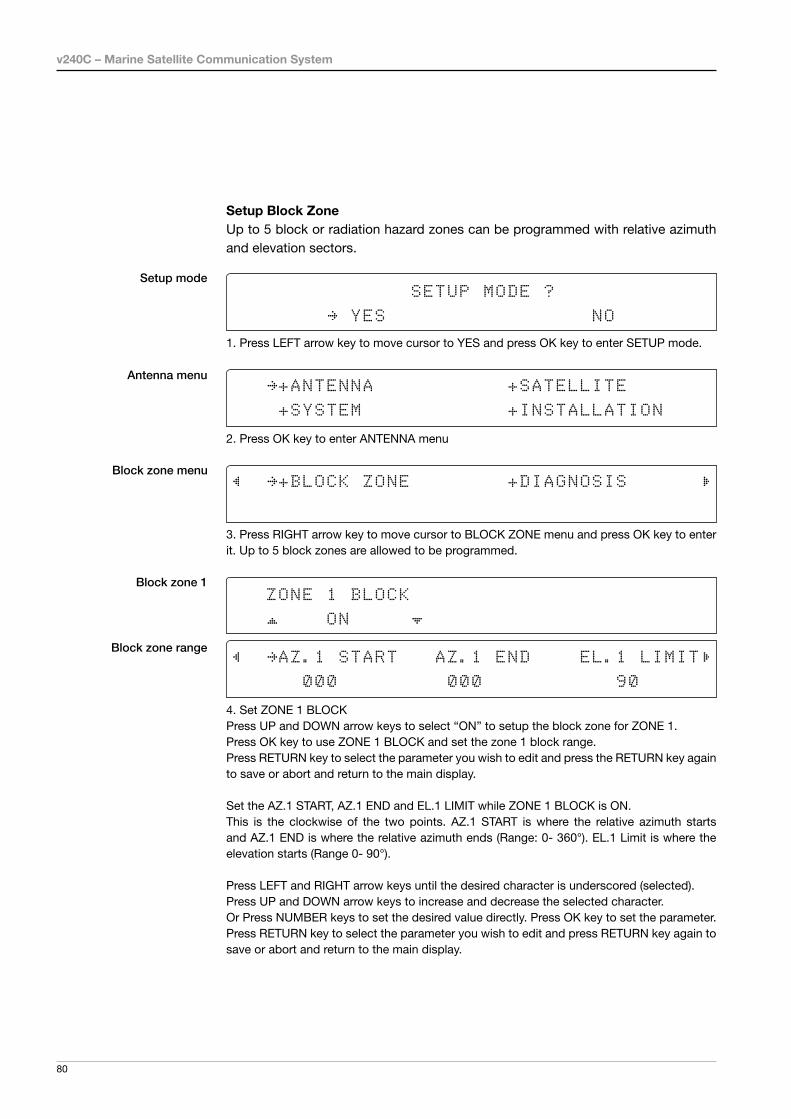
Setup Block Zone Up to 5 block or radiation hazard zones can be programmed with relative azimuth and elevation sectors.
Block zone menu
Block zone range
Block zone 1
Antenna menu
Setup mode SETUP MODE ?
YES NO
1. Press LEFT arrow key to move cursor to YES and press OK key to enter SETUP mode.
+ANTENNA +SATELLITE
+SYSTEM +INSTALLATION
2. Press OK key to enter ANTENNA menu
+BLOCK ZONE +DIAGNOSIS
3. Press RIGHT arrow key to move cursor to BLOCK ZONE menu and press OK key to enter it. Up to 5 block zones are allowed to be programmed.
ZONE 1 BLOCK
ON
AZ.1 START AZ.1 END EL.1 LIMIT
000 000 90
4. Set ZONE 1 BLOCKPress UP and DOWN arrow keys to select “ON” to setup the block zone for ZONE 1.Press OK key to use ZONE 1 BLOCK and set the zone 1 block range.Press RETURN key to select the parameter you wish to edit and press the RETURN key again to save or abort and return to the main display.
Set the AZ.1 START, AZ.1 END and EL.1 LIMIT while ZONE 1 BLOCK is ON.This is the clockwise of the two points. AZ.1 START is where the relative azimuth starts and AZ.1 END is where the relative azimuth ends (Range: 0- 360°). EL.1 Limit is where the elevation starts (Range 0- 90°).
Press LEFT and RIGHT arrow keys until the desired character is underscored (selected).Press UP and DOWN arrow keys to increase and decrease the selected character.Or Press NUMBER keys to set the desired value directly. Press OK key to set the parameter. Press RETURN key to select the parameter you wish to edit and press RETURN key again to save or abort and return to the main display.

81
OPERATING THE ACU
Block zone 2
Save
ZONE 2 BLOCK
OFF
5. ZONE 2 to ZONE 5 BLOCK setting is same as ZONE 1 BLOCK.Press OK key to set ZONE 2 BLOCK and set next parameter.
SAVE ?
YES NO
6. Press LEFT arrow key to move cursor to YES and press OK key to save and execute the current settings. Or press RIGHT arrow key to move cursor to NO and press OK key to abort and return to the main display.

v240C – Marine Satellite Communication System
82
Diagnossis ProceduresRefer to the diagnosis codes for the test results.
Single diagnostic test result
Full diagnostic test result
Diagnosis menu
Antenna menu
Setup mode SETUP MODE ?
YES NO
1. Press LEFT arrow key to move cursor to YES and press OK key to enter SETUP mode.
+ANTENNA +SATELLITE
+SYSTEM +INSTALLATION
2. Press OK key to enter ANTENNA menu.
+BLOCK ZONE +DIAGNOSIS
3. Press arrow keys to move cursor to DIAGNOSIS menu and press OK key to enter it.
DIAGNOSIS COMMUNICATION
FULL TEST READY
4. Press UP and DOWN arrow keys to select a full diagnostic test or single diagnostic test and press OK key to execute the selected diagnostic test.Menus for DIAGNOSIS are FULL TEST and CODE 101 ~ CODE 115.
DIAGNOSIS FULL TESTING
FULL TEST - -
5. A full diagnostic is successfully completed.
DIAGNOSIS COMMUNICATION
CODE 101 RESULT : PASSED
6. A single diagnostic test is successfully completed.

83
OPERATING THE ACU
Diagnosis Code:CODE 101: The data communication between the antenna and the ACU is tested.CODE 102: The azimuth motor is tested. CODE 103: The elevation motor is tested.CODE 104: The cross-level motor is tested.CODE 105: The azimuth encoder is tested. CODE 106: The cross-level encoder is tested.CODE 107: The rate sensor is tested.CODE 108: The tilt sensor is tested.CODE 109: The sensor box motor is tested.CODE 110: The LNB is tested.CODE 111: The LNB pol motor is tested.CODE 112: The sub-reflector is tested. (Skip for v-Series communication products)CODE 113: The antenna power is tested.CODE 114: The ACU power is tested.CODE 115: The receiver power is tested. (Skip for v-Series communication products)
An example of test result: ••2•••••••••-••-
•: test is passed2: test is failed (CODE102)–: test is skipped (TVRO products only)?: test is in process

v240C – Marine Satellite Communication System
84
Satellite SettingsLoad Satellite
Load
Load sat menu
Load satellite
Satellite menu
Setup mode SETUP MODE ?
YES NO
1. Press LEFT arrow key to move cursor to YES and press OK key to enter SETUP mode.
+ANTENNA +SATELLITE
+SYSTEM +INSTALLATION
2. Press RIGHT arrow key to move cursor to SATELLITE and press OK key to enter it.
+LOAD SAT. +EDIT SAT.
+ADD SAT. +CHECK NID
3. Press OK key to enter LOAD SAT. menu.
LOAD SATELLITE
[1] ASIA6AH 125.00E
4. Press UP and DOWN arrow keys to select satellite that you wish to track.Press OK key to load the selected satellite.
LOAD ?
YES NO
5. Press LEFT arrow key to move cursor to YES and press OK key to load the selected satellite and execute the current settings. Or press RIGHT arrow key to move cursor to NO and press OK key to abort and return to the main display.

85
OPERATING THE ACU
Edit Satellite Information
Edit satellite
Edit longitude & name
Edit sat menu
Satellite menu
Setup mode SETUP MODE ?
YES NO
1. Press LEFT arrow key to move cursor to YES and press OK key to enter SETUP mode.
+ANTENNA +SATELLITE
+SYSTEM +INSTALLATION
2. Press RIGHT arrow key to move cursor to SATELLITE and press OK key to enter it.
+LOAD SAT. +EDIT SAT.
+ADD SAT. +CHECK NID
3. Press RIGHT arrow key and OK key to enter EDIT SAT. menu.
EDIT SATELLITE
[1] ASIA6AH 125.00E
4. Press UP and DOWN arrow keys to select the satellite that you wish to edit and press OK key to edit the selected satellite.
LONGITUDE EDIT NAME
125.00E ASIA6AH
5. Edit satellite orbit position, LONGITUDE and satellite NAME.
v240C – Marine Satellite Communication System
86
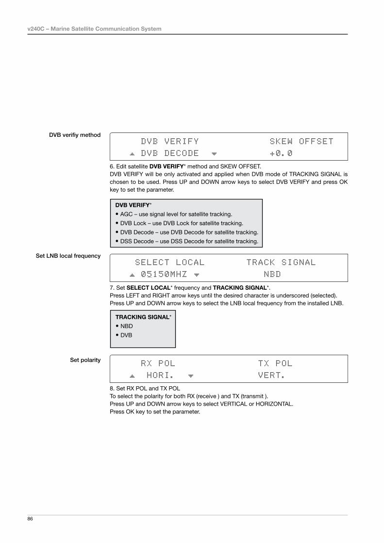
DVB VERIFY SKEW OFFSET
DVB DECODE +0.0
6. Edit satellite DVB VERIFY* method and SKEW OFFSET.DVB VERIFY will be only activated and applied when DVB mode of TRACKING SIGNAL is chosen to be used. Press UP and DOWN arrow keys to select DVB VERIFY and press OK key to set the parameter.
DVB VERIFY*
• AGC – use signal level for satellite tracking.
• DVB Lock – use DVB Lock for satellite tracking.
• DVB Decode – use DVB Decode for satellite tracking.
• DSS Decode – use DSS Decode for satellite tracking.
SELECT LOCAL TRACK SIGNAL
05150MHZ NBD
7. Set SELECT LOCAL* frequency and TRACKING SIGNAL*.Press LEFT and RIGHT arrow keys until the desired character is underscored (selected).Press UP and DOWN arrow keys to select the LNB local frequency from the installed LNB.
RX POL TX POL
HORI. VERT.
8. Set RX POL and TX POLTo select the polarity for both RX (receive ) and TX (transmit ).Press UP and DOWN arrow keys to select VERTICAL or HORIZONTAL.Press OK key to set the parameter.
DVB verifiy method
Set polarity
Set LNB local frequency
TRACKING SIGNAL*
• NBD
• DVB

87
OPERATING THE ACU
Set NBD tracking frequency
Save
Set DVB tracking frequency DVB FREQ. SYMBOL NID
04080MHz 27500KHz 0X0888
9. Set DVB FREQUENCY, SYMBOL RATE and NID when DVB mode of TRACKING SIGNAL is chosen to be used.
45,000 is the maximum allowed symbol rate value. NID (network ID) range is from 0 x 0000 to 0 x FFFF (hexadecimal digit).
Press LEFT and RIGHT arrow keys until the desired character is underscored (selected).Press UP and DOWN arrow keys to increase or decrease the value.Or press NUMBER keys to set the desired value directly.Press OK key to set the parameter.
NBD FREQ. BANDWIDTH
1070.000MHz 01.000MHz
10. Set NBD IF FREQUENCY and BANDWIDTH when NBD (Narrow Band Detection) mode of TRACKING SIGNAL is chosen to be used.
Press LEFT and RIGHT arrow keys until the desired character is underscored (selected).Press UP and DOWN arrow keys to increase or decrease the value.Or press NUMBER keys to set the desired value directly. Press OK key to set the parameter.
SAVE ?
YES NO
11. Press LEFT arrow key to move cursor to YES and press OK key to save and execute the current settings. Or press RIGHT arrow key to move cursor to NO and press OK key to abort and return to the main display.

v240C – Marine Satellite Communication System
88
SETUP MODE ?
YES NO
1. Press LEFT arrow key to move cursor to YES and press OK key to enter SETUP mode.
+ANTENNA +SATELLITE
+SYSTEM +INSTALLATION
2. Press RIGHT arrow key to move cursor to SATELLITE and press OK key to enter it.
+LOAD SAT. +EDIT SAT.
+ADD SAT. +CHECK NID
3. Press DOWN arrow key and OK key to enter ADD SAT. menu.
LONGITUDE EDIT NAME
000.00E SAT.00
4. Set satellite LONGITUDE and satellite NAME.
DVB VERIFY SKEW OFFSET
DVB DECODE +00.0
5. Edit the satellite DVB VERIFY* and SKEW OFFSET.
DVB VERIFY will be only activated and applied when DVB mode of TRACKING SIGNAL is chosen to be used. Press UP and DOWN arrow keys to select DVB VERIFY and press OK key to set the parameter.
DVB VERIFY*
• AGC – use signal level for satellite tracking.
• DVB Lock – use DVB Lock for satellite tracking.
• DVB Decode – use DVB Decode for satellite tracking.
• DSS Decode – use DSS Decode for satellite tracking.
Addition of Satellite Information
DVB verify method
Add sat menu
Set longitude & name
Setup mode
Satellite menu
89
OPERATING THE ACU
Set LNB local frequency
Set polarity
Sat NBD tracking frequency
Set DVB tracking frequency
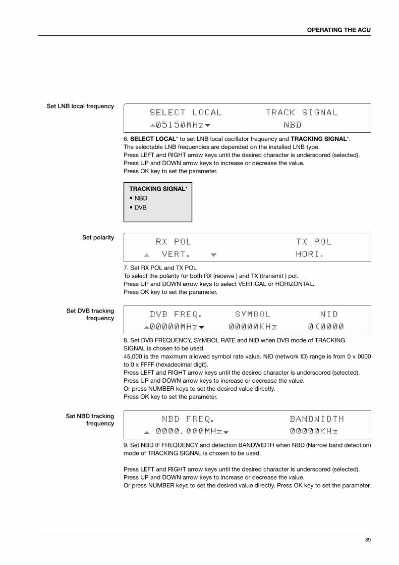
SELECT LOCAL TRACK SIGNAL
05150MHz NBD
6. SELECT LOCAL* to set LNB local oscillator frequency and TRACKING SIGNAL*.The selectable LNB frequencies are depended on the installed LNB type.Press LEFT and RIGHT arrow keys until the desired character is underscored (selected).Press UP and DOWN arrow keys to increase or decrease the value.Press OK key to set the parameter.
RX POL TX POL
VERT. HORI.
7. Set RX POL and TX POLTo select the polarity for both RX (receive ) and TX (transmit ) pol.Press UP and DOWN arrow keys to select VERTICAL or HORIZONTAL.Press OK key to set the parameter.
DVB FREQ. SYMBOL NID
00000MHz 00000KHz 0X0000
8. Set DVB FREQUENCY, SYMBOL RATE and NID when DVB mode of TRACKINGSIGNAL is chosen to be used.45,000 is the maximum allowed symbol rate value. NID (network ID) range is from 0 x 0000 to 0 x FFFF (hexadecimal digit).Press LEFT and RIGHT arrow keys until the desired character is underscored (selected).Press UP and DOWN arrow keys to increase or decrease the value.Or press NUMBER keys to set the desired value directly.Press OK key to set the parameter.
NBD FREQ. BANDWIDTH
0000.000MHz 00000KHz
9. Set NBD IF FREQUENCY and detection BANDWIDTH when NBD (Narrow band detection) mode of TRACKING SIGNAL is chosen to be used.
Press LEFT and RIGHT arrow keys until the desired character is underscored (selected).Press UP and DOWN arrow keys to increase or decrease the value.Or press NUMBER keys to set the desired value directly. Press OK key to set the parameter.
TRACKING SIGNAL*
• NBD
• DVB

v240C – Marine Satellite Communication System
90
Save
Check NID
NID verification
Check NID menu
Setup mode
Satellite menu
SETUP MODE ?
YES NO
1. Press LEFT arrow key to move cursor to YES and press OK key to enter SETUP mode.
+ANTENNA +SATELLITE
+SYSTEM +INSTALLATION
2. Press RIGHT arrow key to move cursor to SATELLITE menu and press OK key to enter it.
+LOAD SAT. +EDIT SAT.
+ADD SAT. +CHECK NID
3. Press DOWN arrow key and OK key to enter CHECK NID menu.
[CHECK NID] F:12490 S:27490 0X00AD
PRESS OK RECEIVED NID[0X0000]
4. CHECK NID is to verify the NID (Network ID) of the current tracking transponder.Press OK key to verify the NID [0 x 0000] only when “ PRESS OK” function is activated. “PRESS OK” function will only be activated when DVB Lock signal is confirmed by the antenna. However, “NO LOCK” message will be displayed if DVB Lock signal can’t be confirmed.
SAVE ?
YES NO
10. Press LEFT arrow key to move cursor to YES and press OK key to save and execute the current settings. Or press RIGHT arrow key to move cursor to NO and press OK key to abort and return to the main display.
91
OPERATING THE ACU
Setting local
System Settings
System menu
Set local frequency menu
LNB info
Setup mode
Save
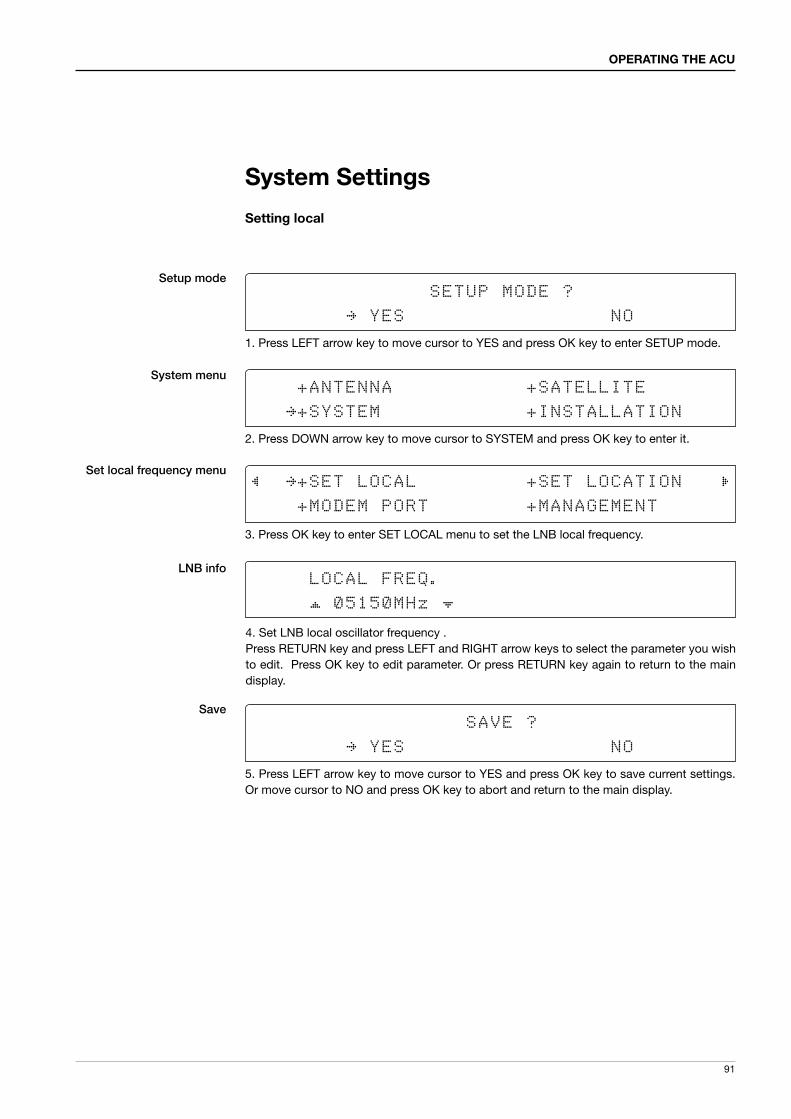
SETUP MODE ?
YES NO
1. Press LEFT arrow key to move cursor to YES and press OK key to enter SETUP mode.
+ANTENNA +SATELLITE
+SYSTEM +INSTALLATION
2. Press DOWN arrow key to move cursor to SYSTEM and press OK key to enter it.
+SET LOCAL +SET LOCATION
+MODEM PORT +MANAGEMENT
3. Press OK key to enter SET LOCAL menu to set the LNB local frequency.
LOCAL FREQ.
05150MHz
SAVE ?
YES NO
5. Press LEFT arrow key to move cursor to YES and press OK key to save current settings. Or move cursor to NO and press OK key to abort and return to the main display.
4. Set LNB local oscillator frequency . Press RETURN key and press LEFT and RIGHT arrow keys to select the parameter you wish to edit. Press OK key to edit parameter. Or press RETURN key again to return to the main display.

v240C – Marine Satellite Communication System
92
Setting Location
System menu
Set location menu
Gyro type and Baud rate
Setup mode SETUP MODE ?
YES NO
1. Press LEFT arrow key to move cursor to YES and press OK key to enter SETUP mode.
+ANTENNA +SATELLITE
+SYSTEM +INSTALLATION
2. Press DOWN arrow key to move cursor to SYSTEM and press OK key to enter it.
+SET LOCAL +SET LOCATION
+MODEM PORT +MANAGEMENT
3. Press RIGHT arrow key to move cursor to SET LOCATION and press OK key to enter it.
GYRO TYPE BAUD RATE
NMEA 4800
4. Set the ship’s GYRO TYPE* and BAUD RATEA search pattern 1 or 3 will be initiated according to which GYRO TYPE is selected and the existence of the gyro input. Set the BAUD RATE as 4800, 9600, 19200 or 38400 according to your device.
A search pattern 1 will be initiated automatically if the gyro input does not exist and the gyro type is selected other than GROUND TEST.
NOTE: The bow offset will not be saved automatically if Search 1 pattern is initiated. In this case, the antenna will need to re target the desired satellite using Search 1 every time if the antenna restarts.
Gyro search type Setting of Heading Device
Existence of Heading Data No DeviceNMEANMEA 2000
Ground Test
With Heading Data Search 1 Search 3 Search 3
Without Heading Data Search 1 Search 1 Search 3
GYRO TYPE*
• NO DEVICE
• NMEA
• NMEA 2000
• GROUND TEST

93
OPERATING THE ACU
Heading
Latitude & longitude
Save
LATITUDE LONGITUDE
37.00N 126.50E
5. Set the current LATITUDE and LONGITUDE Press LEFT and RIGHT arrow keys until the desired character is underscored (selected). Press UP and DOWN arrow keys to increase or decrease the value. Or press NUMBER keys to set the desired value directly. Press the OK key to set the parameter.
HEADING
000.0
6. Entry of ship’s heading is not required when your system is connected to a NMEA(0813) or NMEA2000 Heading Gyrocompass output. Ensure that the supported Gyro Type is set correctly. For v240, if the ship’s gyrocompass output is Step-by-Step (SBS) or Synchro, separate purchase of a gyro converter is required.
SAVE ?
YES NO
7. Press LEFT arrow key to move cursor to YES and press OK key to save current settings. Or move cursor to NO and press OK key to abort and return to the main display.

v240C – Marine Satellite Communication System
94
Setting Modem Port
System menu
Modem port menu
Set Mediator & modem type
Setup mode SETUP MODE ?
YES NO
1. Press LEFT arrow key to move cursor to YES and press OK key to enter SETUP mode.
+ANTENNA +SATELLITE
+SYSTEM +INSTALLATION
2. Press DOWN arrow key to move cursor to SYSTEM menu and press OK key to enter it.
+SET LOCAL +SET LOCATION
+MODEM PORT +MANAGEMENT
3. Press DOWN arrow keys to move cursor to COM. PORT menu and press OK key to enter it.
USE MEDIATOR MODEM TYPE
NO I DIRECT-I/O
4. USE MEDIATOR is to enable the usage of MEDIATOR if the antenna is connected to the Intellian Dual VSAT Mediator.
NOTE: USE MEDIATOR must be disabled if there is no MEDIATOR connected to the ACU. Improper setting of this parameter will cause your ACU’s modem interface to work incorrectly.
MODEM TYPE* is to select a proper data communication port and protocol on the ACU to interface with the satellite modem. The settings related to the modem interface will be set automatically once the modem type is selected.
The options on the next page will be displayed and required to be set if "USER SETTING" is selected.
MODEM TYPE*
• USER SETTING
• IDIRECT-I/O
• IDIRECT-AMIP
• COMTECH-I/O
• COMTECH-ROSS
• SATLINK
• HUGHES

95
OPERATING THE ACU
M ODEM PORT PROTOC OL
ETHERNET I /O CONSOLE
5. MODEM PORT* is to select a proper data communication port on the ACU to interface with the modem.
PROTOCOL*
• I/O CONSOLE: is a protocol for interchanging information (GPS Out, TX mute, and modem lock) between the ACU (through Console port) and the modem.
• OPEN AMIP: is an ASCII based protocol developed by iDirect for interchanging information between the ACU and the modem. OpenAMIP is not intended for any other purposes except to allow the ACU and the modem to perform synchronized automatic beam switching (ABS).
• SERIAL GPS: is a protocol for sending GPS Out information from the ACU (through RS232/422 port) to the modem.
• ROSS: ROSS Open Antenna Management (ROAM) protocol was developed by Comtech EF Data Corporation to offer a common management interface for Comtech EF Data's Roaming Oceanic Satellite Server (ROSS) and ACU.
6. GPS OUT SENTENCE* is to select the GPS OUT SENTENCE type. USE TX MUTE is to select whether or not to use the USE TX MUTE function from the satellite modem. A transmit inhibit output from the ACU will disable/mute the modem transmit via a voltage whenever the antenna is blocked, searching, or is mis-pointed 0.5 degrees from the peak satellite position.
Set modem protocol
Use TX mute G PS O UT SENTE NCE USE TX MUTE
GPGLL YES
GPS OUT SENTENCE*
• GPGLL
• GPGGA
• SIMPLE GPGGA
MODEM PORT*
• ETHERNET
• RS422
• RS232
PROTOCOL* is to select a proper communication protocol on the ACU tointerface with the modem.

v240C – Marine Satellite Communication System
96
TX mute activation
Save
TX MUTE ACTIVE
LOW
8. TX MUTE ACTIVE is a transmit inhibit output from the ACU to disable/mute the modem transmit through a 5 V (HIGH) or 0 V (LOW) current whenever the antenna is blocked, searching, or is mis-pointed 0.5º from peak satellite position. TX MUTE ACTIVE item will only be activated when PROTOCOL is set as I/O CONSOLE.
SAVE ?
YES NO
Use EXT.LOCK USE EXT.LOCK EXT. LOCK ACTIVE
YES LOW
7. USE EXT. LOCK is to select whether or not to use an external lock signal from the satellite modem. USE EXT. LOCK item will only be activated when PROTOCOL is set as I/O CONSOLE.
EXT. LOCK ACTIVE is referring that the modem lock output from the modem is providing a logic input through a 5 V (HIGH) or 0 V (LOW). current to the ACU to identify when it is on the correct satellite. EXT. LOCK ACTIVE item will only be activated when PROTOCOL is set as I/O
CONSOLE.
9. Press LEFT arrow key to move cursor to YES and press OK key to save current settings. Or move cursor to NO and press OK key to abort and return to the main display.

97
OPERATING THE ACU
System Management
System menu
Backup and restore menu
Setup mode SETUP MODE ?
YES NO
1. Press LEFT arrow key to move cursor to YES and press OK key to enter SETUP mode.
+ANTENNA +SATELLITE
+SYSTEM +INSTALLATION
2. Press DOWN arrow key to move cursor to SYSTEM menu and press OK key to enter it.
+SET LOCAL +SET LOCATION
+MODEM PORT +MANAGEMENT
3. Press arrow keys to move cursor to BACKUP & RESTORE menu and press OK key to enter it.
Select process type
•••
••
USE BLUETOOTH: To use bluetooth. If the select process type is set to "Bluetooth", the data communication between Antenna and ACU will be disconnected. Refer topage 131 for setting up bluetooth connection.UPGRADE FROM USB: to upgradethe system by using the firmware files from the specified folder in the USB flash drive.COPY LOG TO USB: to copy the antenna log data from the system to the USB flash drive.
SELECT PROCESS TYPE
BACKUP USER DATA
4. Press UP and DOWN arrow keys to SELECT PROCESS TYPE*Press OK key to set the parameter and the processing message will be displayed.
SELECT PROCESS TYPE* BACKUP USER DATA: to backup the antenna settings set by user. RESTORE USER DATA: to restore the antenna by using the backup user data.

v240C – Marine Satellite Communication System
98
Key Lock
System menu
Set key lock and password
Key lock menu
Setup mode SETUP MODE ?
YES NO
1. Press LEFT arrow key to move cursor to YES and press OK key to enter SETUP mode.
+ANTENNA +SATELLITE
+SYSTEM +INSTALLATION
2. Press DOWN arrow key to move cursor to SYSTEM menu and press OK key to enter it.
+KEY LOCK
3. Press arrow keys to move cursor to KEY LOCK menu and press OK key to enter it.
KEY LOCK UNLOCK P/W
ON 1590
4. Press UP and DOWN arrow keys to choose whether or not to use key pad lock when entering the SETUP mode or saving the satellite information. Setup the password for entering the key pad lock. The factory default is 1590.

99
OPERATING THE ACU
PC CONTROLLER SOFTWARE
Introduction
PC to ACU Communication Setup
Main Menu
Controller MenusPosition & Manual SearchTracking Information of Current SatelliteTracking Information of LibraryVersion, Tracking Parameter & Block ZoneDiagnosis, Search Parameter & Sensor Adjust

v240C – Marine Satellite Communication System
100
The PC Controller Software for the Intellian v80G has been created for the user to easily set up the antenna using a personal computer.
Introduction
Antenna PC controller

101
PC CONTROLLER SOFTWARE
PC to ACU Communication Setup
Enter “Communication Information” menu to setup the data communication between the PC and the ACU.
• Access ACU through Serial Communication
- Connect a 9 pin serial cable from the PC INTERFACE connector on the ACU to the 9-pin serial port on the PC. Use USB-Serial Adapter if there is no 9-pin serial port on the PC.
- Execute PC Controller Software by inserting the supplied CD-ROM into the CD-ROM drive of the PC.
- The baud rate of the ACU is 57600.- Select a COM port which is not occupied by other devices.- Click Connect button
• Access ACU through Network Communication
- Turn off wireless connection while using this method. - Execute PC Controller Software by inserting the supplied CD-ROM into the CD-
ROM drive of the PC. - Enter the ACU’s IP address (Factory default IP: 192.168.0.223)- Enter the ACU’s port number (Factory default port: 4002) - Click Connect button
NOTE: If the remote access PC is located in the same network group with the ACU, the ACU can be accessed through the internal IP address. But, if the remote access PC is located outside of the network group, the ACU’s IP address should be changed by the IP address assigned by the network service provider. Refer to page 117 for changing the ACU’s IP address.
Establish a data communication
WARNING: The data volume will grow very quickly if Network Communication is in use. Intellian recommends to use Remote Web Access to access the ACU (refer to page 91).

v240C – Marine Satellite Communication System
102
• Enable the Usage of External Lock & TX Mute
- Connect a RJ45 cable from the Ethernet connector on the ACU to the modem or connect a 9 pin serial cable from the RS232/422 connector on the ACU to the modem.
- Select a proper data communication port (RS232/422/Ethernet) to interface with the modem.
- Select a proper communication protocol (I/O Console/OpenAMIP/Serial GPS) to interface with the modem.
- Enable / disable the usage of TX MUTE function.- TX Mute is a transmit inhibit output from the ACU to disable/mute the modem
transmit through a 5 V (HIGH) or 0 V (LOW) current whenever the antenna is blocked, searching, or is mis-pointed 0.5 degrees from peak satellite position. This item will only be activated when the modem protocol is set as I/O Console.
- Enable/disable the usage of External Lock function. This function will only be activated when the modem protocol is set as I/O Console.
- Modem Lock is referring that modem lock output from the modem provides a logic input through a 5 V (HIGH) or 0 V (LOW) current to the ACU to identify when it is on the correct satellite. This item will only be activated when the modem protocol is set as I/O Console.
• Select GPS Out Sentence Type
- Select GPS OUT SENTENCE type (GPGLL/GPGGA/Simple GPGGA)
• Use Bluetooth - Bluetooth: The data communication between the ACU and the antenna will be terminated once the Bluetooth function is activated. This function is to establish the data communication between the antenna and your PC/Laptop for maintenance regardless of the ACU.- Modem Lock: Setup the modem lock sent from your PC/laptop to the antenna while Bluetooth is in use. - Heading Connect: Setup the heading connection information sent from your PC/ laptop to the antenna while Bluetooth is in use. - Heading: Setup the heading value sent from your PC/laptop to the antenna while Bluetooth is in use.
• Use Mediator
-Enable the usage of Mediator if the antenna is connected to the Intellian Dual VSAT Mediator. Disable this function if there is no Mediator connected to the ACU. Improper setting of this parameter will cause your ACU’s modem inter face to work incorrectly.
• Select Modem
-Select a proper data communication port and protocol on the ACU to interface with the satellite modem. The settings related to the modem interface will be set automatically once the modem type is selected. If USER SETTING is selected, a separate input of modem port and modem protocol is required.

103
PC CONTROLLER SOFTWARE
Main Menu
Main menu
Restore Position Backup Position
• Controller Menus- Position (GPS, Heading, Bow) & Manual search- Tracking Information of Current Satellite- Tracking Information of Library- Version, Tracking Parameter & Block Zone- Diagnosis, Search Parameter & Sensor Adjust- Communication Information
• Command Buttons- Restart: Exit SETUP mode and restart antenna.- Setup: Enter SETUP mode.- Get Antenna Information: Obtain the information stored in the antenna.
- Save Satellite: Save the current settings if they are able to locate the satellite (in Tracking mode). It can reduce the satellite acquisition time after restarting the system.
- Backup: Backup antenna information to ACU/PC.- Restore: Restore the antenna by using saved information in ACU/PC.- Reboot: Reboot the antenna.

v240C – Marine Satellite Communication System
104
In “SETUP” mode, “Back Up Position” or “Restore Position” message will pop up if “Backup” or “Restore” button is pressed. Backup File (*.ibf) and Report File (*.rpt) will be generated on the PC if “Back Up to PC” button is pressed. You can open a report file using notepad software.NOTE: These two functions are only available for ACU Version 1.07 or later.
• Status- Search 1: A search pattern 1 will automatically be initiated when the ship’s heading
input does not exist or fails. The search cycle will repeat until the antenna receives the lock signal from the modem or the DVB transponder of the target satellite is decoded by the antenna.
- Search 2: Search 2 is reserved for future use.- Search 3: A Search pattern 3 is a search pattern 3 will automatically be initiated
when AGC / SIG falls below the current tracking level threshold value. Once the desired signal is found and above the predefined tracking threshold, the ACU will enter to tracking mode.
- Tracking: Antenna is tracking the target satellite.- Initialize: Antenna or ACU is initializing.- Setup: Antenna is in SETUP mode.- Comm: Antenna is able to be communicated.
• Local frequency- Local freq: Display LNB local oscillator frequency.- Signal level: Display signal level. It shows “DVB” when DVB mode of tracking
signal is chosen to be used and “NBD” when NBD mode of tracking signal is chosen to be used.
• System versions- Product ant: Display antenna model and “PCU” firmware version.- Product ACU: Display ACU model and “ACU main” firmware version.
• TX enable:- TX enable: TX function is enabled and ready to transmit.- Enable mode: Not in SETUP mode.- Blockage: Antenna is not facing the predefined block zone(s).- Pointing: Antenna is pointing to the target satellite.- Modem lock: Satellite modem is sending a logic input to the ACU to identify when
the antenna tracks onto the correct satellite.- LNB rotate: LNB is not rotating.
NOTE: The TX function will be enabled (shows blue dot ) only if all of the factors listed above show a “blue” dot. If any of the factors listed above show a “gray” dot or a "red" dot, the TX function will be disabled (shows red dot).Exception: If “Use TX Mute” is set as “NO”, the TX function will be enabled regardless of which factor listed above shows a “gray” dot or a “red” dot.

105
PC CONTROLLER SOFTWARE
Position & Manual Search
Set the GPS and ship’s heading information to acquire the satellite signal and use move step function to find the satellite signal manually.
Antenna angle, GPS and ship’s heading information
Antenna Current GPS- Antenna Current GPS: Display current antenna GPS and Ship’s heading
information. Enter SETUP mode and click check box in front of Edit GPS/Edit Heading to set GPS / ship’s heading. After the desired value is entered press Set GPS/Set Heading button to save the settings.
- Set GPS: Set antenna GPS information manually.- Set Heading: Set ship’s heading information manually.
Heading Device- Heading Device: Set ship’s heading device (NONE, NMEA, NMEA2000, GROUND TEST )
Antenna Angle 1- Absolute: Display the current absolute angle position of the antenna (azimuth,
elevation, and satellite skew). - Target Angle: Display the target angle position of the antenna calculated by the
GPS and the satellite information. - Relative: Display the current relative azimuth angle position of the antenna.
Bow- Bow: Display and set bow offset if needed.
Skew Information- LNB pol Information: Display LNB pol angle and satellite skew angle.- Pol sensor calibration: Calibrate the sensor (potentiometer).
Antenna Angle 2- Antenna Angle 2: Move antenna azimuth and elevation position and LNB pol angle
to find the desired satellite manually. Select polarity among the drop down list and click on Set Polrarity button to apply the setting.
Controller Menus

v240C – Marine Satellite Communication System
106
Tracking Information of Current Satellite
Set the tracking mode and tracking frequency of the current satellite.Set the LNB local frequency to its corresponding voltage power supply.
Satellite Information- Satellite information: Display the current satellite name, longitude position and
satellite skew.
Tracking Common Info- Local Frequency & LNB Power: Display the current LNB frequency which is in use
and its corresponding voltage power supply.- Tracking: Display/ set the current tracking mode (DVB/ NBD).- RX POL and TX POL: Set RX and TX polarity (Vertical/Horizontal).
DVB- DVB: Set satellite tracking information (frequency, symbol rate, NID and verify
type) for DVB tracking mode.
NBD- NBD: Set satellite tracking information (frequency and bandwidth) for NBD tracking
mode.
Local Frequency- Local frequency: Display or set LNB local frequency and its corresponding LNB
power supply.
NOTE: Select the Swedish Microwave (SMW) PLL LNB type from the Drop-Down List. If the LNB type is different than SMW, manually inputting the LNB local frequency is required.
Set the current satellite tracking information

107
PC CONTROLLER SOFTWARE
Tracking Information Library
Open the pre-programmed satellite library file and upload it to the ACU.Build your own custom library and save it to an external hard drive/PC.
Get data from ACU
- Get data from ACU: Obtain the pre-programmed satellite library file from the ACU while the antenna is in SETUP mode.
Load Satellite
- Load satellite: Upload the pre-programmed satellite information in the library.
Library
- Open library from PC: Open the satellite library file from the supplied Intellian CD or from the external hard drive/PC. (File format: *.ilf)
- Upload library to ACU: Upload the satellite library file to ACU.- Save library to PC: Save the current library setting to the PC.- Edit Library: Edit the satellite information of the selected satellite.- Add Library: Add the satellite information as defined in the current settings.- Delete Library: Delete the selected satellite from the library settings.
NOTE: It is required to click the “Save Library to PC” button after “Edit Library”, “Add Library “, or “Delete Library” button is clicked. These functions are only available for ACU Version 1.07 or later.
Library information

v240C – Marine Satellite Communication System
108
Version, Tracking Parameter & Block Zone
Display the antenna, ACU firmware versions and serial number.Setup the antenna blockage zone(s).Setup the antenna parameters.
Display antenna versions and tracking parameters
Software Information- Software information: Display antenna and ACU firmware versions and library
version.
Product Information- Product information: Display antenna and ACU serial numbers.
Parameter Setting- DVB: Display /setup current detect level threshold and tracking level threshold
when DVB tracking mode is chosen to be used.
- NBD: Display /setup current detect level threshold and tracking level threshold when NBD tracking mode is chosen to be used.
- TX Enable Threshold: display/ setup TX enable threshold.
Block Zone- Display current block zones by azimuth and elevation sectors. Up to 5 blockage
zones can be programmed.
NOTE: DVB and NBD parameter settings should only be changed by an authorized service technician. Improper setting of these parameters will render your system inoperable. Consult Intellian for changing antenna parameters.

109
PC CONTROLLER SOFTWARE
Display antenna versions and parameters
Tilt Sensor Bias- Tilt sensor bias: Adjust the two solid-state tilt sensors used to provide absolute
cross-level tilt of the antenna and elevation feedback to eliminate long-term pointing drift (error). Tilt bias is required to be adjusted when the antenna control board or sensor box is replaced. Check and see if the bubble is located at the center of the level vial.
- Ready: Make elevation angle go to 0º for tilt sensor bias adjustment.
Conical Range- Conical rage: set conical range while the antenna is on tracking mode.
EL Adjust- EL adjust: The elevation adjustment is to offset the angle difference between the
mechanical elevation angle and actual elevation angle.
Diagnosis, Search Parameter & Sensor Adjust
Set the tilt sensors and calibrate rate sensors.Set the antenna search parameters.Run an antenna diagnostic test.

v240C – Marine Satellite Communication System
110
Rate Sensor- Rate sensor: Rate sensor is to calibrate DC voltage output from the three rate
sensors used to sense antenna motion in azimuth, elevation and cross-level axes. The DC voltage output from each of the rate sensors may vary by an amount which is directly proportional to the direction and rate of motion induced on it. Before calibrating the rate sensors located at the Sensor box, make sure that the antenna is placed on a rigid and flat platform. During the calibration process, the antenna should avoid any motion as it can affect the antenna’s performance. After clicking the “Rate Sensor Bias Check” button, the green dot will be displayed as a ready signal to calibrate the gyro sensor. The red dot (fail) or blue dot (pass) will be displayed once the calibration is completed.
Idle Mode- Idle mode: Release the elevation and cross level motor brakes while the antenna is
in SETUP mode. The antenna can be moved manually during idle mode.
Diagnosis- Diagnosis: The system can carry out the selected full diagnostic test “Test All” or
single diagnostic test. The software will display the diagnostic test results (Blue dot represents “normal”, red represents “abnormal”, yellow represents “skip test” and green represents “the diagnostic test is under process”).

111
REMOTE WEB ACCESS
REmOTE WEb ACCESS
Introduction
Main Page
Antenna SettingsGeneral Information Current Status Ship Information Antenna Position Tracking Information Parameter Setting Modem Setting Block Zone Setting Diagnosis Satellite Information
Antenna / ACU Firmware UpgradeFirmware UpgradeRoll BackUpgrade LogAntenna Log
Ethernet-to-Serial SettingsWireless SettingNetwork Setting Serial SettingSNMP SettingChange Password E2S (Ethernet-to-Serial) Upgrade Save & RebootAccess Log

v240C – Marine Satellite Communication System
112
Introduction With embedded remote access function, the v-Series can be monitored, controlled, and diagnosed remotely from anywhere, anytime through the TCP/IP protocol. This not only can save tremendous time but also save the cost generated from the hundreds of routine maintenance activities such as operating firmware upgrades, tracking parameters resets, and system diagnostic.
• Login page
1. Enter the ACU's IP address into your web browser's address bar to login into the ACU’s internal HTML page. If this system has not been changed from the ACU’s factory default:
IP address: Primary: 192.168.0.223 / Secondary: 10.10.1.12. Choose either to Control & Monitor the ACU or Only Monitor the ACU. 3. Log into the ACU by typing in User Name and Password information. If this
system has not been changed from the factory default: User Name: intellian / Password: 12345678

113
REMOTE WEB ACCESS
Main Page
No. Item Description
1 Control IP Display current IP that controls the ACU.
2 Current IP Display current IP address.
3 Refresh Rate
Display screen refresh rate and time out.The screen will not refresh once the time-out shows 0:00. Exception: If the Refresh Disable Time is set to “OFF” in the Network Setting page, then the clock will show “--:--“ and system will keep monitoring all activities regardless of time-out.
4 Antenna Status Display antenna status.
5 TX Enable Display whether or not the antenna is able to transmit the data.
6 Signal Level Display current signal level.
7 Edit Enable Enable to edit the ACU settings. Ensure the check box is enabled before modifying the settings.
8 Get Antenna Info Obtain current antenna information.
9 Restart Restart antenna system.
10 Setup Enter SETUP mode.
11 Save SatelliteSave current satellite settings.Bow offset will be adjusted and saved automatically.
12 Backup Backup antenna information to ACU.
1 2 3
4 5 6
7 8 9 10 11 12 13 14
15
16
17
18

v240C – Marine Satellite Communication System
114
No. Item Description
13 Restore Restore antenna information from ACU.
14 Logout Logout ACU’s internal HTML page.
15 Antenna Antenna setup menu.
16 Firmware Firmware upgrade menu.
17 Ethernet-to-Serial ACU’s IP address and serial communication setup menus.
18 Wifi Display wifi on/off status.

115
REMOTE WEB ACCESS
No. Item Description
1General Information
Display current antenna information.
2AntennaInformation
Display current antenna information. - Antenna Size: antenna dish size. - Voltage: operation voltage of antenna and ACU.- Antenna Product: antenna model number.- ACU Product: ACU model number. - Antenna Serial Number: antenna serial number.- ACU Serial Number: ACU serial number- System Polarization: antenna polarized feed (Crosspol / Copol).- Tracking Signal: satellite tracking mode (DVB/ NBD)
3Software Information
Display current Antenna and ACU firmware versions and Satellite Library version installed in the system. - Antenna Stabilizer Version- Antenna PCU Version - ACU Main Version- Antenna POL Version (It will display "v-----" if there is no Pol Control Board installed.)
4LNB Local Frequencies(MHz)
Display LNB local frequency and corresponding voltage.
Antenna SettingsGeneral Information
2
3
4
1

v240C – Marine Satellite Communication System
116
Current Status
No. Item Description
1 Current Status Display current antenna status.
2 Status
Display current antenna status.- Search 1: a search pattern 1 will automatically be initiated when the
ship’s heading input does not exist / is failed. The search cycle will repeat until the antenna receives the lock signal from the modem or the DVB transponder of the target satellite is decoded by the antenna.
- Search 2: is reserved for future use.- Search 3: a search pattern 3 will automatically be initiated when
AGC / SIG falls below the current tracking level threshold value. Once the desired signal is found and above the predefined tracking threshold, the ACU will enter to tracking mode.
- Tracking: antenna is tracking the target satellite.- Initialize: antenna or ACU is initializing.- Block: satellite signal is being blocked.- Setup: antenna is in SETUP mode.- Communication: antenna is able to be communicated with ACU.
3 Common Display current LNB local frequency and signal level.
2
3
4
1

117
REMOTE WEB ACCESS
No. Item Description
4 TX Enable
Display whether or not the antenna is able to transmit the data. The TX function will only be enabled (shows BLUE dot ) only if all of the factors listed below shows “BLUE” dot. Exception: If “Use TX Mute” is set as “NO”, the TX function will be enabled regardless of which factor listed below shows “gray” dot or “red” dot.- Enable Mode: antenna is not in SETUP mode. - Blockage: antenna is not facing the predefined block zone(s).- Pointing: antenna is pointing to the target satellite. - Modem Lock: satellite modem is sending a logic input to the ACU to
identify when the antenna tracks on the correct satellite.- LNB Rotate: LNB is not rotating.

v240C – Marine Satellite Communication System
118
Ship Information
No. Item Description
1 Ship Information Display GPS and ship’s gyro information.
2 GPS Display current GPS information. - Longitude (East / West)- Latitude (North / South)
3 Bow Offset Display and set bow offset if needed.
4 Heading Device
Current device: set ship’s heading device. (NONE, NMEA, NMEA 2000, Ground test)If the ship’s gyro input is other than NMEA separate purchase of GYRO Converter is required.- Heading: set ship’s heading information.
1
2
3
4
Ensure the Edit Enable check box is enabled before modifying the settings.

119
REMOTE WEB ACCESS
Antenna Position
1 Antenna Position Display current antenna position.
2 Current Antenna Position
Display current antenna position. - Relative Azimuth: display antenna relative AZ angle. - Absolute Azimuth: display antenna absolute AZ angle.- Elevation: display antenna elevation angle.- LNB Pol Angle: display LNB pol angle.- Heading: display ship’s heading information.
3 Manual MovementMove antenna azimuth and elevation angles and LNB pol angle to find the desired satellite manually.
4 LNB Pol Sensor Calibration Calibrate the LNB pol angle when the control board, potentiometer or belt is replaced.
2
3
4
1

v240C – Marine Satellite Communication System
120
Tracking Information
No. Item Description
1 Tracking InformationDisplay or set current tracking mode and tracking frequency of the target satellite.
2Local FrequencySetting (MHz)
Display LNB’s local frequencies. Display current LNB local frequency which is in use and voltage.
3 Tracking Satellite
Display current tracking mode. - Satellite: display satellite name.- Longitude: display satellite orbit position. - Skew Offset: display Skew offset. - Tracking Method: display current tracking mode (DVB/ NBD).- RX Polarization: display current RX polarization.- TX Polarization display current TX polarization.
4 DVB Information
Display DVB tracking mode’s tracking information. - Frequency: display tracking frequency. - Symbol rate: display symbol rate.- NID: display network ID.- Verify type: display verification type (AGC, DVB, DVB Decode)
1
2
3
4
5

121
REMOTE WEB ACCESS
WARNING: Ensure the Edit Enable check box is enabled before modifying the settings.
No. Item Description
5 NBD Information Display NBD tracking mode’s tracking information.- Frequency: display tracking IF frequency.- Bandwidth: display detection bandwidth.

v240C – Marine Satellite Communication System
122
Parameter Setting
1
2
3
4
5
6
7

123
REMOTE WEB ACCESS
No. Item Description
1 Parameter Setting
Setup antenna search & tracking parameters. These parameters should only be changed by an authorized service technician. Improper setting of these parameters will render your system inoperable.
2Search & Tracking Parameter Setting
DVB Detect and Tracking Level Threshold: display / set current detect level threshold and tracking level threshold when DVB tracking mode is chosen to be used.- NBD Detect and Tracking Level Threshold: display / set
current detect level threshold and tracking level threshold when NBD tracking mode is chosen to be used.
- Enable Threshold: display / set TX enable threshold.- Wait time: set the time-out for automatic initiation of a search
after the signal level drops below the pre-defined threshold value.
- Search Step: set increment step size. - Search 1 & 3 Range: set Search 1 & 3 search range. Search
is conducted in a two-axis pattern consisting of alternate movements in azimuth and elevation as forming expanding square.
- Search 2 Range: is reserved for future use.
3 Tilt Sensor Bias
Adjust the two solid-state tilt sensors used to provide absolute cross-level tilt of the antenna and elevation feedback to eliminate long-term pointing drift (error). Tilt bias is required to be adjusted when the antenna control board or sensor box is replaced. Check to see whether or not the bubble is located at the center of the level vial.
4 Elevation Adjust Adjust the angle difference between the mechanical elevation angle and actual elevation angle.
5Rate Sensor Adjust
Calibrate DC voltage output from the three rate sensors used to sense antenna motion in azimuth, elevation and cross-level axes. During the calibration process, the antenna should avoid any motion as it can affect the antenna’s performance.
6 Idle Mode Release the elevation and cross level motor brakes while the antenna is in SETUP mode. The antenna can be moved manually during the mode.
7 Reboot Reboot the system.
Ensure the Edit Enable check box is enabled before modifying the settings.

v240C – Marine Satellite Communication System
124
Modem Setting
No. Item Description
1 Modem Setting Set the modem interface.
2 Modem
- Modem Type: is to select a proper data communication port and protocol on the ACU to interface with the satellite modem. The settings related to the modem interface will be set auto-matically once the modem type is selected (USER SETTING, IDIRECT-I/O, IDREICT-AMIP, COMTECH-I/O, COMTECH-ROSS, SATLINK). However, it is required to set Item “Inter-face” separately if USER SETTING is selected.
- Use Mediator: enable the usage of Mediator if the antenna is connected to the Intellian Dual VSAT Mediator. Use Mediator must be set to “NO” if there is no MEDIATOR connected to the ACU. Improper setting of this parameter will cause your ACU’s modem interface to work incorrectly.
3 Interface
- Modem Port: is to select a proper data communication port on the ACU to interface with the satellite modem (RS232/422/Ethernet).
- Modem Protocol: is to select a proper communication protocol on the ACU to interface with the modem (I/O Console, OpenAMIP, Serial GPS, ROSS)
- GPS Out Sentence: is to select the GPS out sentence type (GPGLL/GPGGA/SIMPLE GPGGA)
- USE Modem Lock: is to select whether or not to use external lock signal from the satellite modem.
- USE TX Mute: is to select whether or not to use TX mute function from the satellite modem.
1
2
3
4

125
REMOTE WEB ACCESS
- TX Mute: is a transmit inhibit output from the ACU to disable/mute the modem transmit through a 5V (High) or 0V(LOW) current whenever the antenna is blocked, searching, or is mis-pointed 0.5° from peak satellite position.
- Modem Lock: is the modem lock output from the modem which provides a logic input through a 5V (High) or 0V(LOW) current to the ACU to identify when it is on the correct satellite.
Note: TX Mute and Modem Lock items will only be activated when the modem protocol is set as I/O Console.
4Set ModemConfiguration
-Configure your modem settings.
WARNING: Ensure the Edit Enable check box is enabled before modifying the settings.

v240C – Marine Satellite Communication System
126
Block Zone Setting
No. Item Description
1Block Zone Setting
Up to 5 block zones are allowed to be programmed.
2 Block Zone
This is the clockwise of the two points. AZ. START is where the rela-tive azimuth starts and AZ. END is where the relative azimuth ends (Range: 0 - 360°). EL. Limit is where the elevation starts (Range 0 - 90°).
1
2

127
REMOTE WEB ACCESS
Diagnosis
No. Item Description
1 Diagnosis Execute antenna diagnostic test.
2 Diagnosis
Select to run a full diagnosis test or single diagnosis test.-Serial Comm.: test the data communication between the
antenna and the ACU.-Motor AZ: test the azimuth motor.-Motor EL: test the elevation motor.-Motor CL: test the cross-level motor.-Encoder AZ: test the azimuth encoder.-Gyro Senor: test the gyro sensor.-Tilt Sensor: test the tilt sensor.-Sensor Box Limit: test the sensor box motor.-LNB: test the LNB.-Skew: test the LNB skew motor.-Antenna Power: test the antenna power.-ACU Power: test the ACU power.-Home Sensor: test the Home sensor.
WARNING: Ensure the Edit Enable check box is enabled before modifying the settings.
1
2

v240C – Marine Satellite Communication System
128
Satellite Information
1
2
3
4
5
6
7
8
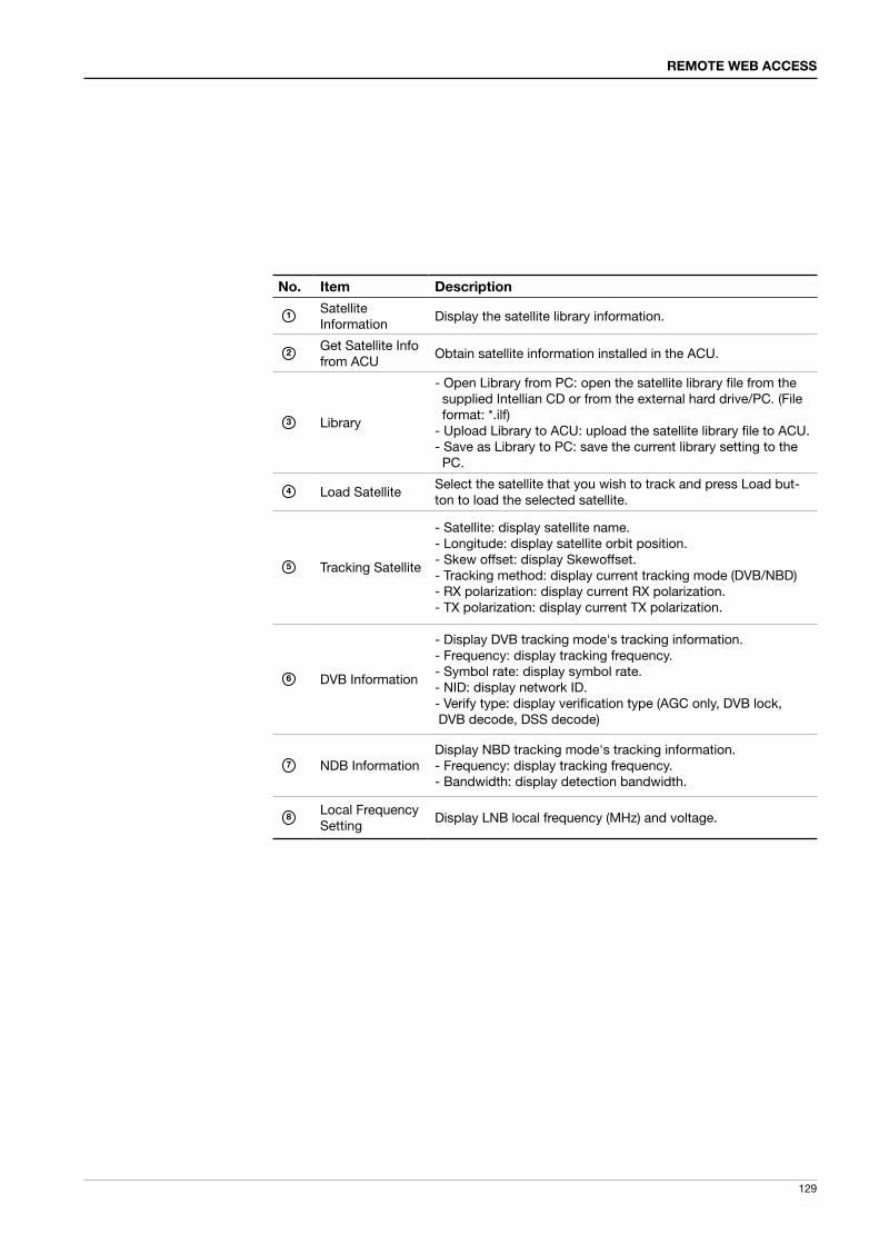
129
REMOTE WEB ACCESS
No. Item Description
1SatelliteInformation
Display the satellite library information.
2Get Satellite Info from ACU
Obtain satellite information installed in the ACU.
3 Library
- Open Library from PC: open the satellite library file from the supplied Intellian CD or from the external hard drive/PC. (File format: *.ilf) - Upload Library to ACU: upload the satellite library file to ACU. - Save as Library to PC: save the current library setting to the PC.
4 Load SatelliteSelect the satellite that you wish to track and press Load but-ton to load the selected satellite.
5 Tracking Satellite
- Satellite: display satellite name.- Longitude: display satellite orbit position.- Skew offset: display Skewoffset.- Tracking method: display current tracking mode (DVB/NBD)- RX polarization: display current RX polarization.- TX polarization: display current TX polarization.
6 DVB Information
- Display DVB tracking mode's tracking information.- Frequency: display tracking frequency.- Symbol rate: display symbol rate.- NID: display network ID.- Verify type: display verification type (AGC only, DVB lock, DVB decode, DSS decode)
7 NDB InformationDisplay NBD tracking mode's tracking information.- Frequency: display tracking frequency.- Bandwidth: display detection bandwidth.
8Local Frequency Setting
Display LNB local frequency (MHz) and voltage.

v240C – Marine Satellite Communication System
130
Backup & Restore
No. Item Description
1
2
Backup
RestoreEnter Backup & Restore page. (Setup mode is required)
3 TargetBackup antenna information to ACU/PC or Restore antenna by using the saved information ACU/PC.
4 Backup Backup antenna information.
5 Restore Restore antenna information.
1 2
3
4
5

131
REMOTE WEB ACCESS
Antenna/ACU Firmware UpgradeFirmware Upgrade
No. Item Description
1 Firmware UpgradeUpgrade antenna and ACU firmware version. Browse and select the firmware package file to upload.
Upgrade Steps1. Select the upgrade package file.2. Click on “Start Upload” button to transfer the Firmware package file (“*.fwp”) to
E2S (Ethernet to serial) module.
3. After the package file is transferred, it’ll show “upgrade from vx.xx Version to vx.xx Version”. Enable the check box to select the firmware file that you wish to upgrade.
4. Click on “Start Upgrade” button.
1

v240C – Marine Satellite Communication System
132
5. It’ll display information about the upgrade process status on full screen.
Firmware upgrade status page
Upgrade process status page
6. If the firmware is successfully upgraded, it’ll display “The firmware update is completed.”
7. Click on "Back to main page" to go out of the screen. To verify the upgraded firmware version, go to the right-side menu of "General information".
Upgrade complete page

133
REMOTE WEB ACCESS
Roll Back
No. Item Description
1 Roll Back Roll back antenna and ACU firmware to previous package version or latest package version.
1

v240C – Marine Satellite Communication System
134
Upgrade Log
No. Item Description
1 Upgrade Log Display log information of firmware upgrade.
1

135
REMOTE WEB ACCESS
Antenna Log
No. Item Description
1 Antenna Log Display log information of antenna.
2 GPS Log OptionDisable: Does NOT download the GPS information stored Log fileEnable: Downloads the GPS information stored Log file
3 Log DownloadExecute Start Download button to proceed.It will open a new pop-up window for log download.
1
2
3
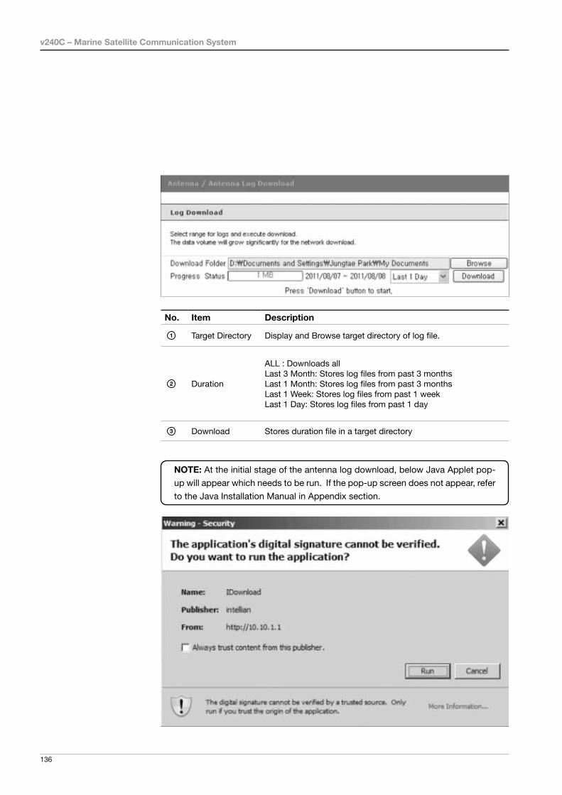
v240C – Marine Satellite Communication System
136
NOTE: At the initial stage of the antenna log download, below Java Applet pop-
up will appear which needs to be run. If the pop-up screen does not appear, refer
to the Java Installation Manual in Appendix section.
No. Item Description
1 Target Directory Display and Browse target directory of log file.
2 Duration
ALL : Downloads allLast 3 Month: Stores log files from past 3 monthsLast 1 Month: Stores log files from past 3 monthsLast 1 Week: Stores log files from past 1 weekLast 1 Day: Stores log files from past 1 day
3 Download Stores duration file in a target directory

137
REMOTE WEB ACCESS
No. Item Description
1 Wireless Setting Shows Wireless Setting
2 Wireless Network
The E2S supports USB WiFi Network.In order to use the USB WiFi, you need to select the En-able. (With version above 2.10, WiFi Module Version will appear)
Ethernet-to-Serial SettingsWireless Setting
2
3Wireless Network mode
Select an appropriate wireless network mode for the cur-rent environment.
4Wireless Network Name (SSID)
The SSID is the network name shared among all devices in a wireless network. The SSID must be identical for all devices in the wireless network. It is case-sensitive and must not exceed 32 alphanumeric characters, which may be any keyboard character. Make sure this setting is the same for all devices in your wireless network.
3
WARNING: After completing the modification of Ethernet-to-Serial's settings enter Save & Reboot page and click on "Save & Reboot" button. Without doing so, the modified settings will be lost.
1 5
4
6
7
8
9
10
11
12
13
19
18
17
16
15
14
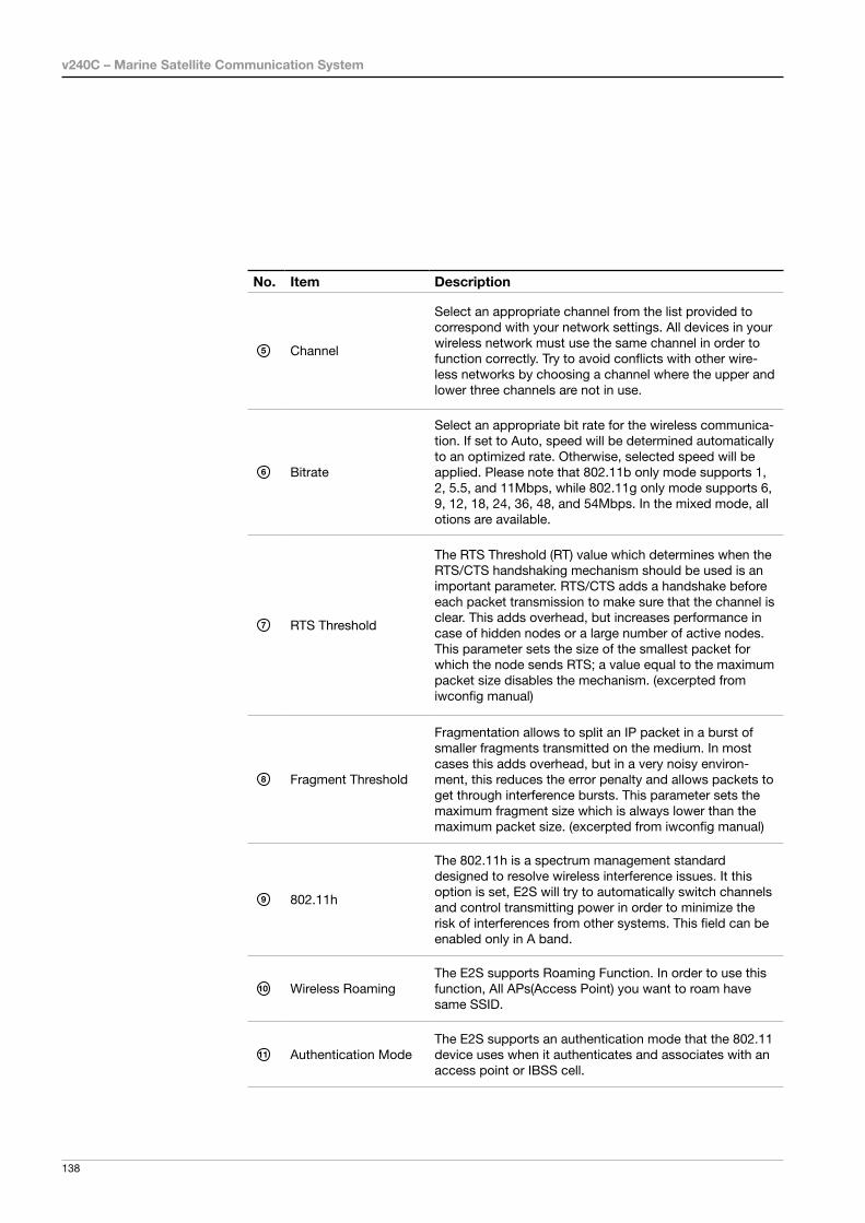
v240C – Marine Satellite Communication System
138
No. Item Description
5 Channel
Select an appropriate channel from the list provided to correspond with your network settings. All devices in your wireless network must use the same channel in order to function correctly. Try to avoid conflicts with other wire-less networks by choosing a channel where the upper and lower three channels are not in use.
6 Bitrate
Select an appropriate bit rate for the wireless communica-tion. If set to Auto, speed will be determined automatically to an optimized rate. Otherwise, selected speed will be applied. Please note that 802.11b only mode supports 1, 2, 5.5, and 11Mbps, while 802.11g only mode supports 6, 9, 12, 18, 24, 36, 48, and 54Mbps. In the mixed mode, all otions are available.
7 RTS Threshold
The RTS Threshold (RT) value which determines when the RTS/CTS handshaking mechanism should be used is an important parameter. RTS/CTS adds a handshake before each packet transmission to make sure that the channel is clear. This adds overhead, but increases performance in case of hidden nodes or a large number of active nodes. This parameter sets the size of the smallest packet for which the node sends RTS; a value equal to the maximum packet size disables the mechanism. (excerpted from iwconfig manual)
8 Fragment Threshold
Fragmentation allows to split an IP packet in a burst of smaller fragments transmitted on the medium. In most cases this adds overhead, but in a very noisy environ-ment, this reduces the error penalty and allows packets to get through interference bursts. This parameter sets the maximum fragment size which is always lower than the maximum packet size. (excerpted from iwconfig manual)
9 802.11h
The 802.11h is a spectrum management standard designed to resolve wireless interference issues. It this option is set, E2S will try to automatically switch channels and control transmitting power in order to minimize the risk of interferences from other systems. This field can be enabled only in A band.
10 Wireless RoamingThe E2S supports Roaming Function. In order to use this function, All APs(Access Point) you want to roam have same SSID.
11 Authentication ModeThe E2S supports an authentication mode that the 802.11 device uses when it authenticates and associates with an access point or IBSS cell.

139
REMOTE WEB ACCESS
No. Item Description
12 Encryption Type
The E2S supports different types of encryption settings for your network. WEP (Wired Equivalent Privacy) is the old, original, now discredited wireless security standard. TKIP is Temporal Key Integrity Protocol. The replacement en-cryption system for WEP. Several features were added to make keys more secure than they were under WEP. AES is Advanced Encryption Standard. This is now the preferred encryption method, replacing the old TKIP.
13 Key Index Select the key index to use for WEP encryption.
14 KeyEnter the key here.- Password for ACU connection via WiFi
15 Connection TypeIP obtaining address method for E2S’s wireless network connection
16 IP Address
Current Wireless IP address E2S is assigned to.When address type is DHCP, current IP is displayed, but it is not editable.When address type is Static IP, manually enter an appro-priate IP address.
17 Subnet Mask
Current wireless subnet mask E2S is assigned to.When address type is DHCP, current subnet mask is dis-played, but it is not editable.When address type is Static IP, manually enter an appro-priate subnet mask.
18 Gateway
Current default gateway for wireless network is assigned to.When address type is DHCP, current default gateway is displayed, but it is not editable.When address type is Static IP, manually enter an appro-priate default gateway.
19 DNS Current default Wireless DNS Address is assigned to.

v240C – Marine Satellite Communication System
140
WARNING: Enter Save & Reboot page and click on “Save & Reboot” button after completing the modification of Ethernet-to-Serial’s settings. Without doing so, the modified settings will be lost.
Network Setting
No. Item Description
1 Network Setting Modify ACU’s Internal IP address.
2 Network Configuration
Modify ACU’s Internal IP address and press Submit but-ton. Go to “Save & Reboot” page and press Save & Reboot button to validate the changes.
IP Address: Factory default (Primary: 192.168.0.223) / (Secondary: 10.10.1.1)Ÿ Subnet Mask: Factory default (255.255.255.0)Ÿ Gateway (modem IP): Factory default (192.168.0.254)
3Browser Configuration
Modify browser refresh rate and refresh disable time.(If “refresh disable time” is checked, then refresh disable
time will be use or otherwise.)
2
3
1

141
REMOTE WEB ACCESS
Serial Setting [1]
No. Item Description
1 Serial Setting Configure Serial port [1] and Serial port [2]
2 Serial Port [1]
Serial Port [1] is to communicate with an external modem via Ethernet. Follow the below instruction to configure Serial port [1] and press Submit button. Go to “Save & Reboot” page and press Save & Reboot button to validate the changes.
• Operation mode: TCP Server • Local socket port: 4001• Baud Rate: 9600 bps • Data Bit: 8 Bit • Stop Bit: 1 Bit • Parity: None • Flow Control: None
The data communication between the modem and the PC may disconnect while setting these parameters.
3 [1][2] Select to configure Serial port [1] or Serial port [2]
1
2
3

v240C – Marine Satellite Communication System
142
Serial Setting [2]
No. Item Description
1 Serial Setting Configure Serial port [1] and port [2]
2 Serial Port [2]
Port [2] is to communicate with the PC Control via Ethernet. Follow the below instruction to configure Serial port 2 and press Submit button. Go to “Save & Reboot” page and press Save & Reboot button to validate the changes.
• Operation mode: TCP Server • Local socket port: 4002 • Baud Rate : 57600 bps • Data Bit : 8 Bit • Stop Bit : 1 Bit • Parity : None • Flow Control : None
The ACU control settings should be applied as same above.
3 [1][2] Select to configure Serial port [1] or Serial port [2]
1
2
3

143
REMOTE WEB ACCESS
SNMP
No. Item Description
1 SNMP v1/v2/v3 AgentEnable or disable the SNMP (Simple Network Management Protocol) agent.
2 V1/2 AttributionConfigure the SNMP v1/v2 attributes (Read-Only, Read-Write, Disable). The community name of SNMP v1 / v2 is “public”.
3 V3 AttributionConfigure the SNMP v3 attributes (Read-Only, Read-Write).
4V3 Username / Password
Set a v3 username & password of the SNMP agent.
5 TRAP IP / PortSet the trap IP address and socket number of the SNMP trap server. Trap feature will be disabled if the trap IP is set to 0.0.0.0.
6System Reset Notification
Enable or disable the system reset SNMP trap notification.
7Port Connect Notification
Enable or disable the port connect SNMP trap notification.
8Port Disconnect Notification
Enable or disable the port disconnect SNMP trap notification.
1
2
3
4
5
6
7
8
NOTE: In SNMP setting, all basic values are set at ‘disabled’, and above 8
categories can be adjust by user. C-band and Ku-band antennas use the same
firmware, and baud-rate of serial port 2 is automatically adjusted by ACU firmware.

v240C – Marine Satellite Communication System
144
Change Password
No. Item Description
1 Change Password Change your login ID (user name) and password.
2 Change IDEnter your current login ID (user name) and new login ID. Press Submit button to validate the changes that are made to the login ID
3 Change Password Enter your current login password and new login password. Press Submit button to validate the changes that are made to the login password.
1
2
3

145
REMOTE WEB ACCESS
Upgrade E2S (Ethernet-to-Serial)
No. Item Description
1 E2S Upgrade Upgrade the firmware of Ethernet-to-Serial module.
2 New Firmware Select a new firmware file and press Start Update button
3 Current Version
to upgrade the firmware of Ethernet-to-Serial module. Current Remote Access VersionCurrent Kernel VersionCurrent Bootloader Version
1
2
3

v240C – Marine Satellite Communication System
146
Firmware Uploaded progress page
Firmware Upgraded progress page
Upgrade Steps1. Click on “Browse” button to select the E2S firmware file (.bin) that you wish to upgrade.
2. Click on “Start Update” button to update the E2S firmware. Wait until the page is loaded.
3. It’ll inform you that the firmware is being uploaded.
4. After the uploading, the upgrade page will show. Do not turn off ACU during this process.

147
REMOTE WEB ACCESS
Rebooting
Lost Connection
6. it’ll reboot the ACU and the connection will be lost. It’ll take around 30 seconds to reboot the E2S module and get the system connection back. (Lost connection message may vary according to web browsers)
5. It takes approximately 120 seconds to complete the firmware upgrade. Once the upgrade is completed and completion message is displayed, ACU power can be turned off and on (ACU will be automatically rebooted).

v240C – Marine Satellite Communication System
148
Save & Reboot
No. Item Description
1 Save & RebootClick on this category to save the modified settings and reboot the system.
2 Save & Reboot Save the modified settings and reboot the system.
3 Reboot without Saving Reboot the system without saving the modified settings.
1
2
3

149
REMOTE WEB ACCESS
Access Log
No. Item Description
1 Access Log Display user’s log information (Date/Time, Login ID and IP)
2 Save Shows the Log information and details
2
1
2

v240C – Marine Satellite Communication System
150
This product is guaranteed by Intellian Technologies Inc., against defect due to faulty workmanship or materials and this guarantee covers for 1 year’s parts from installation or 18 months from shipment.
You are requested to present a copy of the purchase receipt issued by Intellian Technologies, Inc. that presents the date of purchase for after sales service under warranty. In case of failure to present the date of purchase, the warranty period is to be calculated to 30 days after the manufacturing production date.
If you discover a defect, Intellian Technologies, Inc. will, at its option, repair, replace or refund the purchase price of the product at no charge to you, provided you return it during the warranty period, transportation charges prepaid, to the factory direct. Please attach your name, address, telephone number, a description of the problem and a copy of the bill of sale or sales receipt as proof of date of original retail purchase, to each product returned to warranty service. Alternatively, you may bring the product to an Authorized Intellian Technologies, Inc. dealer/distributor for repair.
This Limited Warranty does not apply if the product has been damaged by accident, abuse, misuse or misapplication or has been modified without the written permission of Intellian Technologies, Inc.; if any Intellian Technologies, Inc. serial number has been removed or defaced; or if any factory-sealed part of the system has been opened without authorization.
Warranty

151
REMOTE WEB ACCESS
Appendix: Java Download and Install Guide
NOTE: To run Java applications you must have Java Runtime Environment (JRE) version 6.0 and above installed in your PC/laptop.
2. Installing Java (JRE 6.0 and above) on PC with internet connection.The following window will appear as your initiate the installation of Java. Click Run.
If JRE has not been installed in your PC/laptop, you’ll get the below message box. Click Run button to install it through online or offline download and install methods. After installing JRE, Java Applet will be executed automatically when you access the Antenna Log page.
1. If PC has Java (JRE 6.0 and above) is installed, the Applet will be executed without the installation process.
Java Install Menual

v240C – Marine Satellite Communication System
152
3. Installing Java (JRE 6.0) without Internet ConnectionObtain the Java installation file by referring to section 4 Downloading Java, and install according to section 5 Installing Java.
4. Downloading Java
Method 1. Online method for downloading and installinghttp://www.java.com/en/download/manual.jsp
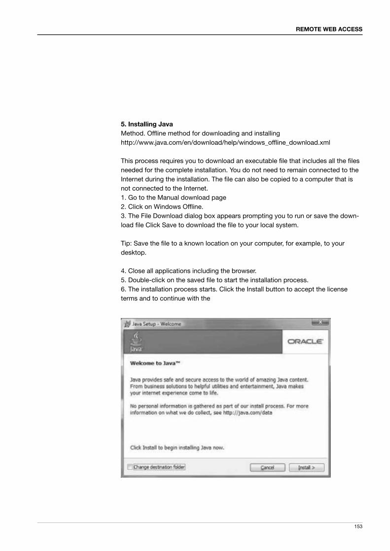
153
REMOTE WEB ACCESS
5. Installing JavaMethod. Offline method for downloading and installinghttp://www.java.com/en/download/help/windows_offline_download.xml
This process requires you to download an executable file that includes all the files needed for the complete installation. You do not need to remain connected to the Internet during the installation. The file can also be copied to a computer that is not connected to the Internet.1. Go to the Manual download page2. Click on Windows Offline.3. The File Download dialog box appears prompting you to run or save the down-load file Click Save to download the file to your local system.
Tip: Save the file to a known location on your computer, for example, to your desktop.
4. Close all applications including the browser.5. Double-click on the saved file to start the installation process.6. The installation process starts. Click the Install button to accept the license terms and to continue with the

v240C – Marine Satellite Communication System
154
6. Oracle has partnered with companies that offer various products. The installer may present you with option to install these programs when you install Java. After ensuring that the desired programs are selected, click the Next button to continue the installation.
7. A few brief dialogs confirm the last steps of the installation process; click Close on the last dialog.
8. This will complete Java installation process.
NOTE: You may need to restart (close and re-open) your browser to enable the java installation in your browser.

155
Technical Specification
Appendix.2Setup WIFI Connection
1. Setting up the ACU in order to access WIFI2. Setting up the PC (Adhoc Mode) in order to access WIFI 3. Remote Access Web Confirmation
Setting up the ACU in order to access WiFi1) Turning on the WIFI switchTurn on the switch on the back side of the ACU, and 30 seconds after authorizing the power supply, confirm if a red light appears on the switch.

v240C – Marine Satellite Communication System
156
1) Setting up my computer’s wireless IP address- Control Panel> Network and Sharing Center > Change Adapter Settings >Right click on the “Bluetooth Wireless Connection”> Click Properties
After selecting TCP/IPv4, click on the properties menu.
Setting up the PC in order to access WiFi

157
Technical Specification
2) Change the network settings to the settings listed below.Case #1If Ethernet to Serial (E2S) Module’s IP is knownThe E2S module’s default IP is 192.168.1.223PC IP : 192.168.1.222Subnet Mask : 255.255.255.0GateWay : 192.168.1.223
Case #2If Ethernet to Serial (E2S) Module’s IP is unknownThe E2S module’s secondary IP is 10.10.10.1PC IP : 10.10.10.2Subnet Mask : 255.255.255.0GateWay : 10.10.10.1
3) Connect WIFI in Ad-hoc mode.After clicking on the Windows Wireless Connection icon, click on ETSW-WIFI (Default)

v240C – Marine Satellite Communication System
158
4) Enter the Network Security Key.Key: intellian1234 (Default)
5) You can confirm the logo and version data by accessing http://192.168.1.223Login by entering the ID / Password listed below.Username: intellian (Default)Password: 12345678 (Default)

159
Technical Specification
6) When you login, Remote Access will check to make sure that all the data within every page is being displayed correctly.

v240C – Marine Satellite Communication System
160
Technical Specification
Radome & Antenna Specification
SizeHeight 4.1m (161.4") (including base frame)
Diameter Ø3.3m (130")
Radome Material / Method FRP / Hand Layout (core mat 2mm, 1PLY 4t)
Weight790 kg / 1738 lbs (Radome + Antenna + Steel base + AC) 663 kg / 1458 lbs (Radome+Antenna+Aluminumbase+AC)
Piece14EA(Bottom 5, Top 5, Cap 1, Hatch 1, Base 1, Base FRP 1)
RF Attenaution 0.5 dB Max. @ Tx Band2.5 dB Max. @ Rx Band* In Tx band Optimal Condition. TBD
Thickness (Predicted) 4.5 mm
Radome Base Specification
SizeHeight 30cm (11.8")
Diameter 185cm (72.8")
Radome Material / Method Steel or Aluminum & Welding
Weight 162Kg (steel), 35Kg (Aluminum)
Air-conditioner & Frame 50 Kg
Item Requirment specification
Pedestal Motion Range
Azimuth Unlimited W/ home sensor (no limit) switch)
Elevation -15° to +120°
Cross-level ± 30º
Pointing StabilizationAccuracy
0.2° peak mis-pointing @max ship motion condition
ApprovalsCE: conforms to EU Directive 89/336/EECFCC: verified to CFR47:Part 15R&TTE
Item Requirment specification
Diameter 2.4m (94.5")
Weight 470Kg
RxFrequency
Standard : 3.6 GHz ~ 4.2 GHzExtended : 3.4 GHz ~ 4.2 GHz
Gain 38.5 dBi @ 3.9 GHz
TxFrequency
Standard : 5.85 GHz ~ 6.425 GHzExtended : 5.85 GHz ~ 6.725 GHz
Gain 41.7 dBi @ 6.18 GHz
Cross-pol isolution Minimum 35 dB
G/T 20.0 dB/K (Clear Sky, 20˚ Elevation)
Antenna Assembly

161
APACHeadquartersIntellian Technologies, Inc.Innovation Center & Factory348-5 Chungho-Ri Jinwi-Myeon Pyeongtaek-Si,Gyeonggi-Do 451-862 KoreaT +82 31 379 1000F +82 31 377 6185
Seoul OfficeIntellian Technologies, Inc.2F Dongik Bldg., 98, Nonhyun-dong, Gangnam-gu,Seoul 135-010, KoreaT +82 2 511 2244F +82 2 511 2235
AmericasIrvine OfficeIntellian Technologies USA, Inc.9004 Research Drive Irvine, CA. 92618, USAT 949 727 4498F 949 271 4183
EMEAEurope OfficeIntellian B.V.Bristolstraat 1, 3047AB Rotterdam, NetherlandsT +31 1 0820 8655F +31 1 0820 8656

![RBS 6201 V2 Installation Instructions [11!05!10]](https://static.documents.pub/doc/80x56/55401a5d550346e26f8b4a1d/rbs-6201-v2-installation-instructions-110510.jpg)


![x360Glitchip v2 Installation[en]](https://static.documents.pub/doc/80x56/552e92904a7959285f8b4948/x360glitchip-v2-installationen.jpg)


