40
Elastic Suspensions for Screens and Shaker Conveyors High dam pening – lo ng lifetime – ov erload proof ROSTA Oscillating Mountings ROSTA
8/10/2019 2013 Oscillating Mountings
http://slidepdf.com/reader/full/2013-oscillating-mountings 1/40
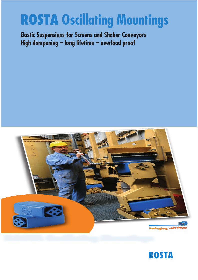
Elastic Suspensions for Screens and Shaker ConveyorsHigh dampening – long lifetime – overload proof
ROSTA Oscillating Mountings
ROSTA
8/10/2019 2013 Oscillating Mountings
http://slidepdf.com/reader/full/2013-oscillating-mountings 2/402.2
www.rosta.com
g
g
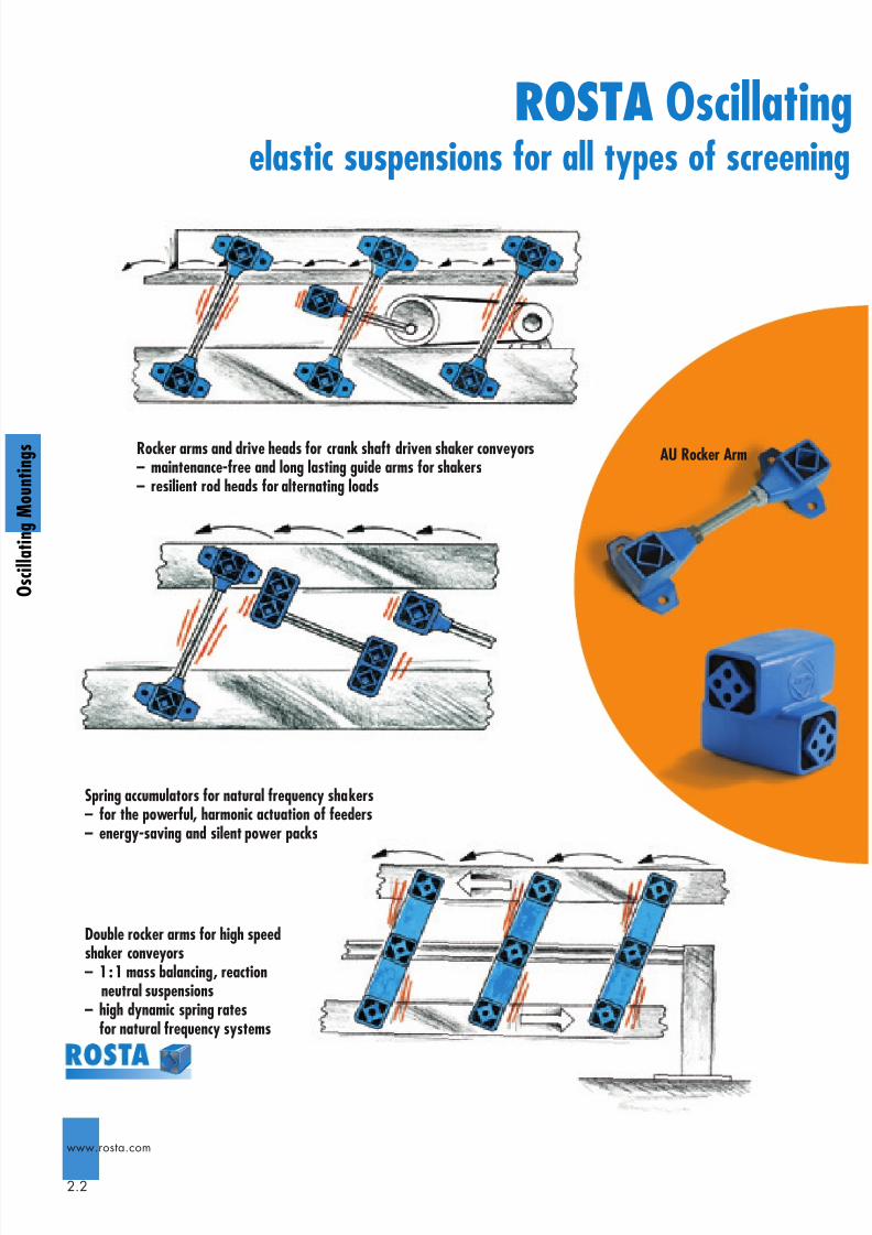
elastic suspensions for all types of screening
Rocker arms and drive heads for crank shaft driven shaker conveyors– maintenance-free and long lasting guide arms for shakers– resilient rod heads for alternating loads
Spring accumulators for natural frequency shakers– for the powerful, harmonic actuation of feeders– energy-saving and silent power packs
Double rocker arms for high speedshaker conveyors– 1 : 1 mass balancing, reaction
neutral suspensions– high dynamic spring rates
for natural frequency systems
AU Rocker Arm
ROSTA Oscillating
8/10/2019 2013 Oscillating Mountings
http://slidepdf.com/reader/full/2013-oscillating-mountings 3/402.3
www.rosta.com
O s c i l l a t i n g M o u n t i n g s
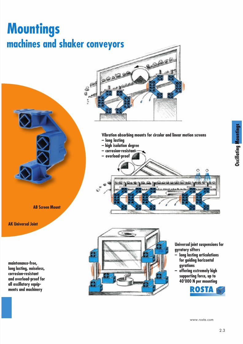
machines and shaker conveyors
AK Universal Joint
AB Screen Mount
Vibration absorbing mounts for circular and linear motion screens– long lasting– high isolation degree– corrosion-resistant– overload-proof
Universal joint suspensions forgyratory sifters– long lasting articulations
for guiding horizontalgyrations
– offering extremely highsupporting force, up to40'000 N per mounting
maintenance-free,long lasting, noiseless,corrosion-resistantand overload-proof forall oscillatory equip-ments and machinery
Mountings
8/10/2019 2013 Oscillating Mountings
http://slidepdf.com/reader/full/2013-oscillating-mountings 4/402.4
www.rosta.com
g
g
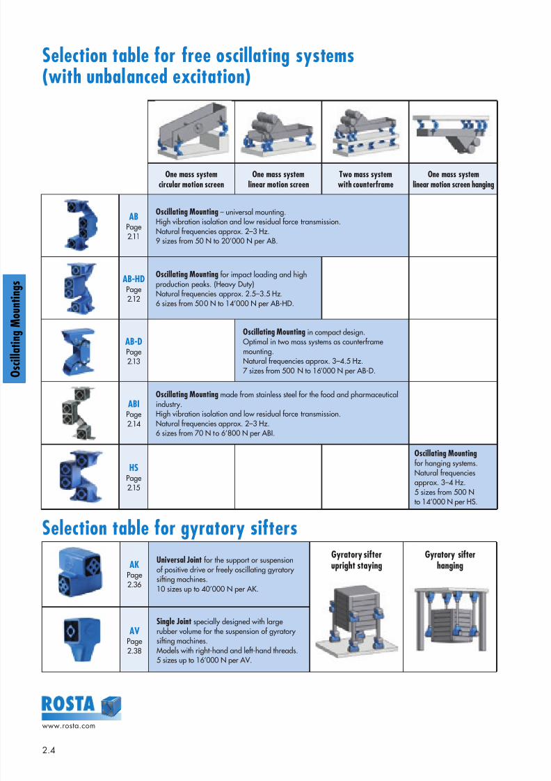
Selection table for free oscillating systems(with unbalanced excitation)
Selection table for gyratory sifters
One mass systemcircular motion screen
One mass systemlinear motion screen
Two mass systemwith counterframe
One mass systemlinear motion screen hanging
ABPage2.11
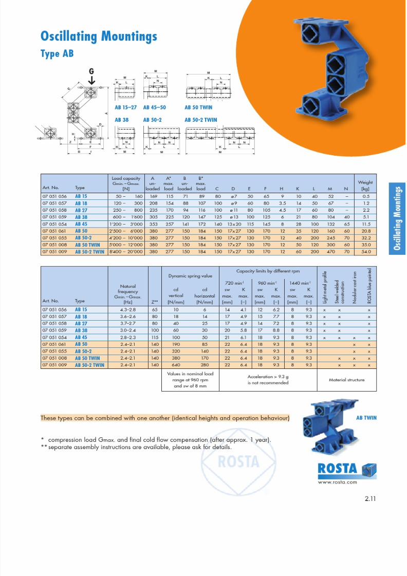
Oscillating Mounting – universal mounting.High vibration isolation and low residual force transmission.Natural frequencies approx. 2–3 Hz.9 sizes from 50 N to 20’000 N per AB.
AB-HDPage2.12
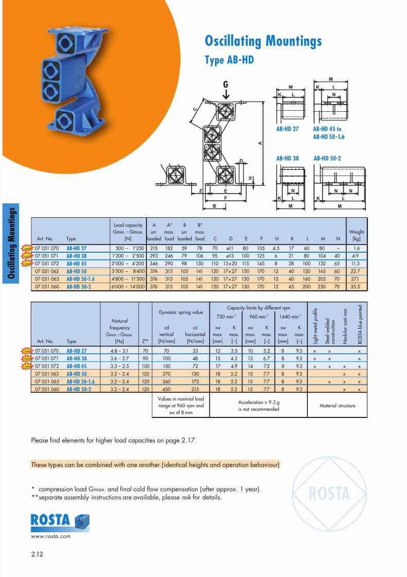
Oscillating Mounting for impact loading and highproduction peaks. (Heavy Duty)Natural frequencies approx. 2.5–3.5 Hz.6 sizes from 500 N to 14’000 N per AB-HD.
AB-DPage2.13
Oscillating Mounting in compact design.Optimal in two mass systems as counterframemounting.Natural frequencies approx. 3–4.5 Hz.7 sizes from 500 N to 16’000 N per AB-D.
ABIPage2.14
Oscillating Mounting made from stainless steel for the food and pharmaceuticalindustry.High vibration isolation and low residual force transmission.Natural frequencies approx. 2–3 Hz.6 sizes from 70 N to 6’800 N per ABI.
HSPage2.15
Oscillating Mounting for hanging systems.Natural frequenciesapprox. 3–4 Hz.5 sizes from 500 Nto 14’000 N per HS.
AKPage2.36
Universal Joint for the support or suspensionof positive drive or freely oscillating gyratorysifting machines.10 sizes up to 40’000 N per AK.
Gyratory sifterupright staying
Gyratory sifterhanging
AVPage2.38
Single Joint specially designed with largerubber volume for the suspension of gyratorysifting machines.Models with right-hand and left-hand threads.5 sizes up to 16’000 N per AV.
8/10/2019 2013 Oscillating Mountings
http://slidepdf.com/reader/full/2013-oscillating-mountings 5/402.5
www.rosta.com
O s c i l l a t i n g M o u n t i n g s
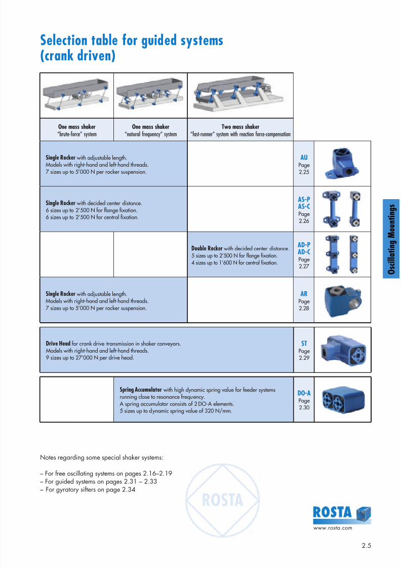
Selection table for guided systems(crank driven)
One mass shaker“brute-force” system
One mass shaker“natural frequency” system
Two mass shaker“fast-runner” system with reaction force-compensation
Single Rocker with adjustable length.Models with right-hand and left-hand threads.7 sizes up to 5’000 N per rocker suspension.
AUPage2.25
Single Rocker with decided center distance.6 sizes up to 2’500 N for flange fixation.6 sizes up to 2’500 N for central fixation.
AS-PAS-CPage2.26
Double Rocker with decided center distance.5 sizes up to 2’500 N for flange fixation. 4 sizes up to 1’600 N for central fixation.
AD-PAD-CPage2.27
Single Rocker with adjustable length.Models with right-hand and left-hand threads.7 sizes up to 5’000 N per rocker suspension.
ARPage2.28
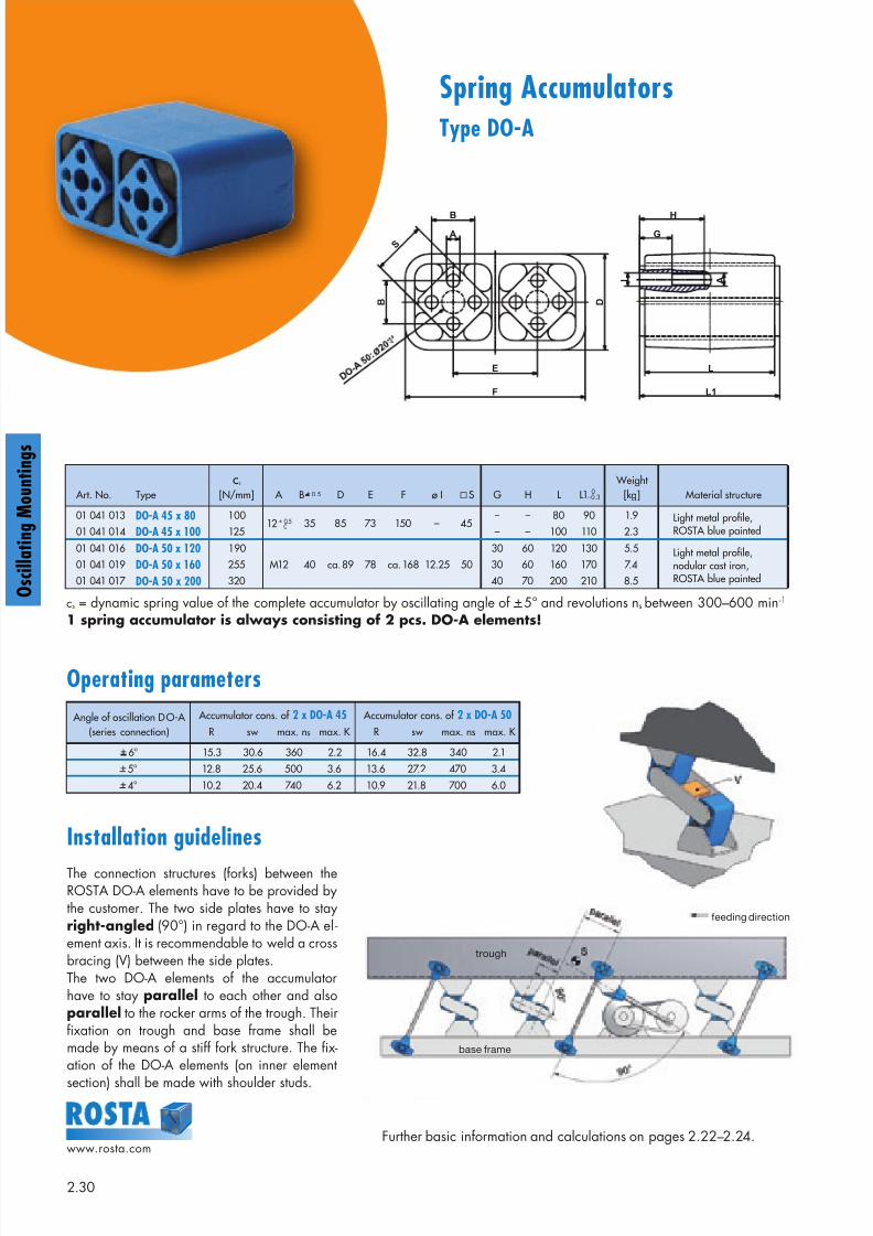
Spring Accumulator with high dynamic spring value for feeder systems
running close to resonance frequency. A spring accumulator consists of 2 DO-A elements.5 sizes up to dynamic spring value of 320 N/mm.
DO-APage2.30
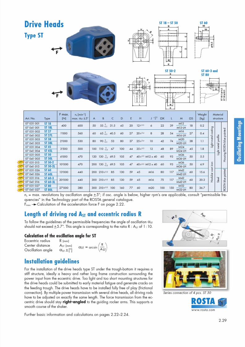
Drive Head for crank drive transmission in shaker conveyors.Models with right-hand and left-hand threads.9 sizes up to 27’000 N per drive head.
STPage2.29
Notes regarding some special shaker systems:
– For free oscillating systems on pages 2.16–2.19– For guided systems on pages 2.31 – 2.33– For gyratory sifters on page 2.34
8/10/2019 2013 Oscillating Mountings
http://slidepdf.com/reader/full/2013-oscillating-mountings 6/402.6
www.rosta.com
g
g
Introduction
Free oscillating systems are either activated in using exciters,unbalanced motors or unbalanced shafts.The oscillation amplitude, type of vibration and the directionof vibration of the screen are determined by the dimension-ing and arrangement of these actuators. The excitationforce, the angle of inclination of the excitation, the inclina-tion of the screen-box and the position of the center ofgravity determine the resulting oscillation amplitude of thedevice. The oscillation amplitude, and thereby the conveyingspeed of the machine, can be optimized by augmentingthese.
ROSTA spring suspensions support the desired oscillationmovement of the screen machine. Through their shape andfunction, they help to achieve a purely linear conveyor mo-tion without unwanted lateral tumbling.
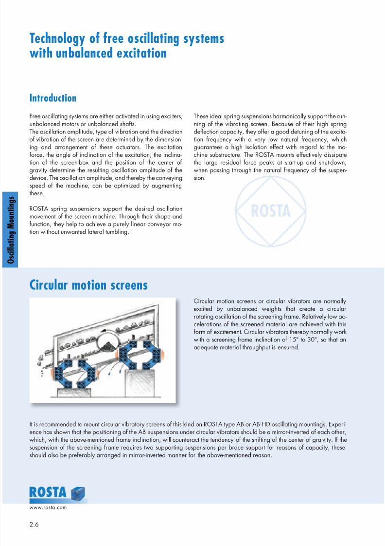
Circular motion screens
Technology of free oscillating systemswith unbalanced excitation
These ideal spring suspensions harmonically support the run-ning of the vibrating screen. Because of their high springdeflection capacity, they offer a good detuning of the excita-tion frequency with a very low natural frequency, whichguarantees a high isolation effect with regard to the ma-chine substructure. The ROSTA mounts effectively dissipatethe large residual force peaks at start-up and shut-down,when passing through the natural frequency of the suspen-sion.
Circular motion screens or circular vibrators are normallyexcited by unbalanced weights that create a circularrotating oscillation of the screening frame. Relatively low ac-celerations of the screened material are achieved with thisform of excitement. Circular vibrators thereby normally workwith a screening frame inclination of 15° to 30°, so that anadequate material throughput is ensured.
It is recommended to mount circular vibratory screens of this kind on ROSTA type AB or AB-HD oscillating mountings. Experi-ence has shown that the positioning of the AB suspensions under circular vibrators should be a mirror-inverted of each other,which, with the above-mentioned frame inclination, will counteract the tendency of the shifting of the center of gravity. If thesuspension of the screening frame requires two supporting suspensions per brace support for reasons of capacity, theseshould also be preferably arranged in mirror-inverted manner for the above-mentioned reason.
8/10/2019 2013 Oscillating Mountings
http://slidepdf.com/reader/full/2013-oscillating-mountings 7/402.7
www.rosta.com
O s c i l l a t i n g M o u n t i n g s
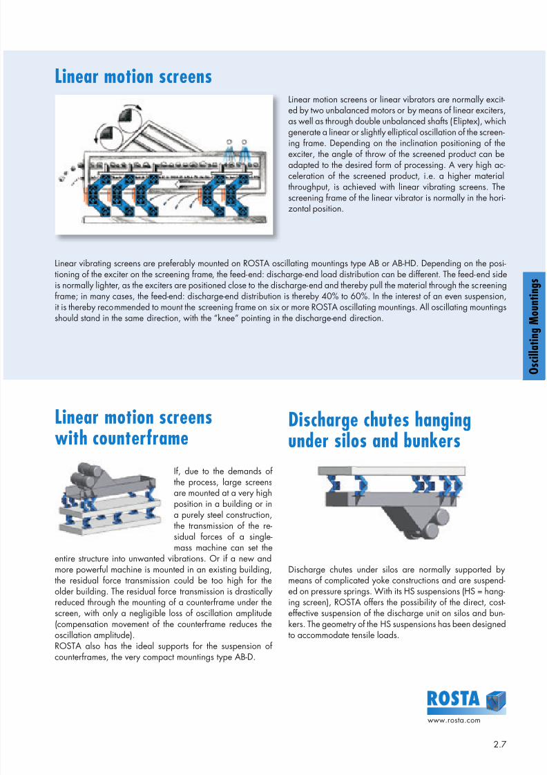
Linear motion screensLinear motion screens or linear vibrators are normally excit-ed by two unbalanced motors or by means of linear exciters,as well as through double unbalanced shafts (Eliptex), which
generate a linear or slightly elliptical oscillation of the screen-ing frame. Depending on the inclination positioning of theexciter, the angle of throw of the screened product can beadapted to the desired form of processing. A very high ac-celeration of the screened product, i.e. a higher materialthroughput, is achieved with linear vibrating screens. Thescreening frame of the linear vibrator is normally in the hori-zontal position.
Linear vibrating screens are preferably mounted on ROSTA oscillating mountings type AB or AB-HD. Depending on the posi-tioning of the exciter on the screening frame, the feed-end: discharge-end load distribution can be different. The feed-end sideis normally lighter, as the exciters are positioned close to the discharge-end and thereby pull the material through the screeningframe; in many cases, the feed-end: discharge-end distribution is thereby 40% to 60%. In the interest of an even suspension,it is thereby recommended to mount the screening frame on six or more ROSTA oscillating mountings. All oscillating mountingsshould stand in the same direction, with the “knee” pointing in the discharge-end direction.
Linear motion screenswith counterframe
Discharge chutes hangingunder silos and bunkers
If, due to the demands ofthe process, large screensare mounted at a very highposition in a building or ina purely steel construction,the transmission of the re-
sidual forces of a single-mass machine can set theentire structure into unwanted vibrations. Or if a new andmore powerful machine is mounted in an existing building,the residual force transmission could be too high for theolder building. The residual force transmission is drasticallyreduced through the mounting of a counterframe under thescreen, with only a negligible loss of oscillation amplitude(compensation movement of the counterframe reduces theoscillation amplitude).ROSTA also has the ideal supports for the suspension ofcounterframes, the very compact mountings type AB-D.
Discharge chutes under silos are normally supported bymeans of complicated yoke constructions and are suspend-ed on pressure springs. With its HS suspensions (HS = hang-ing screen), ROSTA offers the possibility of the direct, cost-effective suspension of the discharge unit on silos and bun-kers. The geometry of the HS suspensions has been designedto accommodate tensile loads.
O s c i l l a t i n g M o u n t i n g s
8/10/2019 2013 Oscillating Mountings
http://slidepdf.com/reader/full/2013-oscillating-mountings 8/402.8
www.rosta.com
g
g
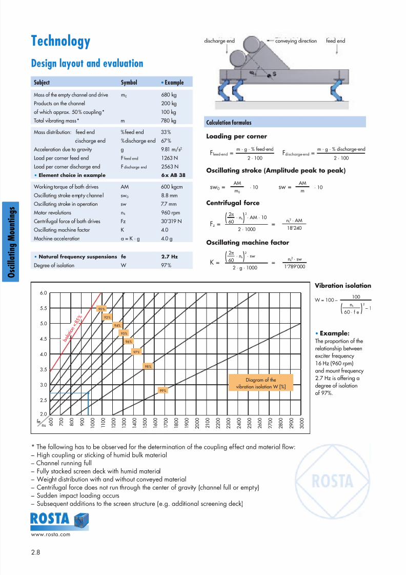
Technology
Design layout and evaluation
Subject Symbol • Example
Mass of the empty channel and drive m0 680 kg
Products on the channel 200 kg
of which approx. 50 % coupling * 100 kg
Total vibrating mass * m 780 kg
Mass distribution: feed end % feed end 33 %
discharge end % discharge end 67 %
Acceleration due to gravity g 9.81 m/s2
Load per corner feed end F feed end 1263 N
Load per corner discharge end F discharge end 2563 N
• Element choice in example 6 x AB 38
Working torque of both drives AM 600 kgcm
Oscillating stroke empty channel sw 0 8.8 mm
Oscillating stroke in operation sw 7.7 mm
Motor revolutions ns 960 rpm
Centrifugal force of both drives Fz 30’319 N
Oscillating machine factor K 4.0
Machine acceleration a = K · g 4.0 g
• Natural frequency suspensions fe 2.7 Hz
Degree of isolation W 97 %
6.0
5.5
5.0
4.5
4.0
3.5
3.0
2.5
2.0
6 0 0
7 0 0
8 0 0
9 0 0
1 0 0 0
1 1 0 0
1 2 0 0
1 3 0 0
1 4 0 0
1 5 0 0
1 6 0 0
1 7 0 0
1 8 0 0
1 9 0 0
2 0 0 0
2 1 0 0
2 2 0 0
2 3 0 0
2 4 0 0
2 5 0 0
2 6 0 0
2 7 0 0
2 8 0 0
2 9 0 0
3 0 0 0
Diagram of the vibration isolation W [%]
* The following has to be observed for the determination of the coupling effect and material flow:– High coupling or sticking of humid bulk material– Channel running full– Fully stacked screen deck with humid material– Weight distribution with and without conveyed material– Centrifugal force does not run through the center of gravity (channel full or empty)– Sudden impact loading occurs
– Subsequent additions to the screen structure (e.g. additional screening deck)
• Example:The proportion of therelationship betweenexciter frequency16 Hz (960 rpm)and mount frequency2.7 Hz is offering adegree of isolationof 97%.
Calculation formulas
Oscillating machine factor
Centrifugal force
Oscillating stroke (Amplitude peak to peak)
Loading per corner
fens
90 %
92 %
94 %
95 %
96 %
97 %
98 %
99 %
sw0 = · 10 sw = · 10 AM AM
m0 m
Ffeed-end =m · g · % feed-end
2 · 100Fdischarge-end =
m · g · % discharge-end
2 · 100
Fz = = · ns · AM · 10
2 · 1000
2π
60 ns2 · AM
18’240
K = = · ns · sw
2 · g · 1000
2π
60 ns2 · sw
1’789’000
W = 100 –
( )
( )
I s o l a t i o
n < 8 5
%
2
2
100
– 1ns
60 · f e( )2
Vibration isolation
discharge end conveying direction feed end
8/10/2019 2013 Oscillating Mountings
http://slidepdf.com/reader/full/2013-oscillating-mountings 9/402.9
www.rosta.com
O s c i l l a t i n g M o u n t i n g s
90° ± 1°
Technology
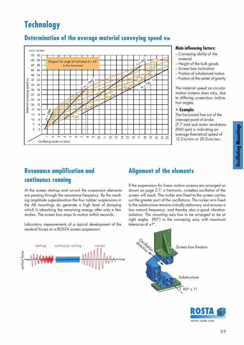
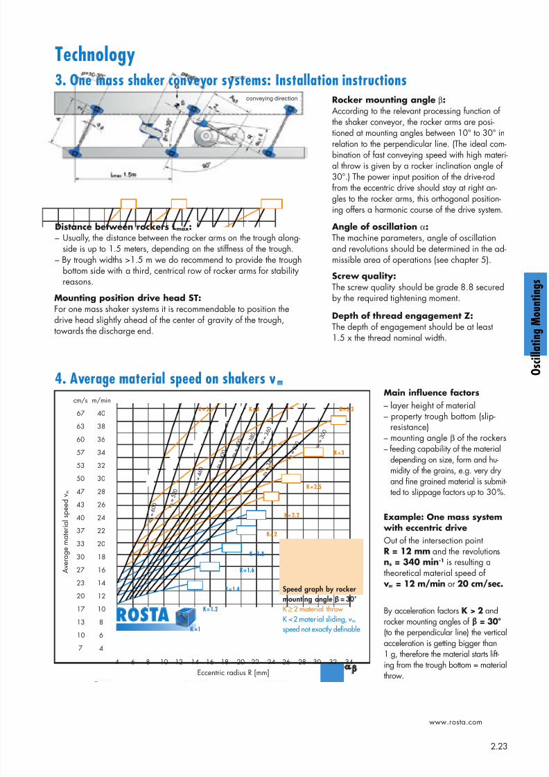
Determination of the average material conveying speed vm
Main influencing factors:– Conveying ability of the
material– Height of the bulk goods– Screen box inclination– Position of unbalanced motors– Position of the center of gravity
The material speed on circularmotion screens does vary, dueto differing screen-box inclina-tion angles.
• Example:The horizontal line out of the
intercept point of stroke(7.7 mm) and motor revolutions(960 rpm) is indicating anaverage theoretical speed of12.3 m/min or 20.5 cm/sec.
Alignment of the elements
If the suspensions for linear motion screens are arranged asshown on page 2.7, a harmonic, noiseless oscillation of thescreen will result. The rocker arm fixed to the screen carriesout the greater part of the oscillations. The rocker arm fixedto the substructure remains virtually stationary and ensures alow natural frequency, and thereby also a good vibrationisolation. The mounting axis has to be arranged to be atright angles (90°) to the conveying axis, with maximumtolerance of ±1°.
Resonance amplification and
continuous runningAt the screen start-up and run-out the suspension elementsare passing through the resonance frequency. By the result-ing amplitude superelevation the four rubber suspensions inthe AB mountings do generate a high level of dampingwhich is absorbing the remaining energy after only a fewstrokes. The screen box stops its motion within seconds.
Laboratory measurements of a typical development of theresidual forces on a ROSTA screen suspension:
Screen box fixation
Substructure
cm/s m/min
53 32
50 3047 28
43 26
40 24
37 22
33 20
30 18
27 16
23 14
20 12
17 10
13 8
10 67 4
3 2
1 2 3 4 5 6 7 8 9 1 0
1 1
1 2
1 3
1 4
1 5
1 6
1 7
1 8
1 9
2 0
2 1
2 2
9 g
8 g
7 g
6 g
5 g
4 g
3 g
2 g
n s = 7
2 0
n s = 9 6 0
n s = 1 4 4 0
n s =
2 8 8 0
Oscillating stroke sw [mm]
M a
t e r i a
l c o n v e y
i n g s p e e
d v m
Diagram for angle of inclination β = 45°to the horizontal
start-up continuous running run-out
v e r t i c a l f o r c e
time
O s c i l l a t i o n
d i r e c t i o n
8/10/2019 2013 Oscillating Mountings
http://slidepdf.com/reader/full/2013-oscillating-mountings 10/402.10
www.rosta.com
g
g
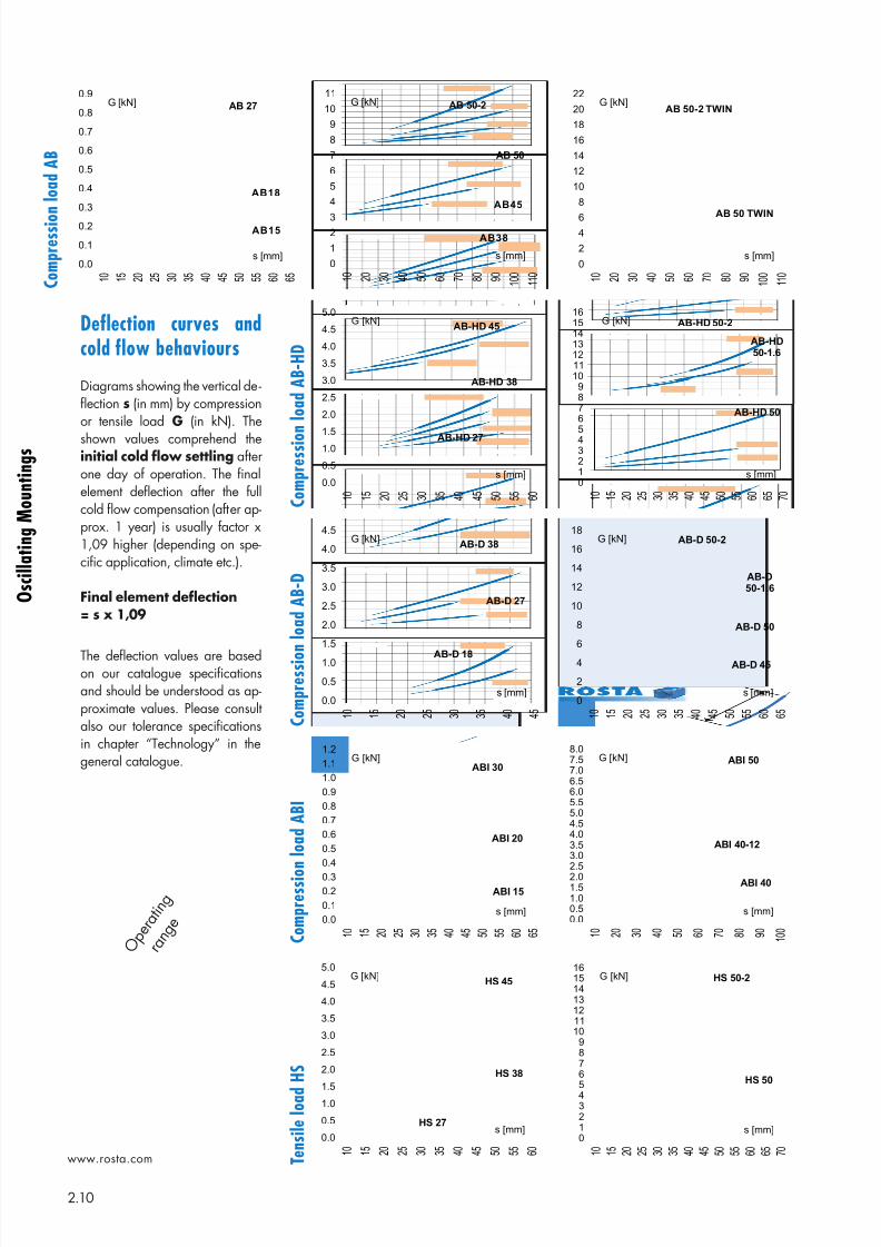
Deflection curves andcold flow behaviours
Diagrams showing the vertical de-flection s (in mm) by compressionor tensile load G (in kN). The
shown values comprehend theinitial cold flow settling afterone day of operation. The finalelement deflection after the fullcold flow compensation (after ap-prox. 1 year) is usually factor x1,09 higher (depending on spe-cific application, climate etc.).
Final element deflection= s x 1,09
The deflection values are basedon our catalogue specificationsand should be understood as ap-proximate values. Please consultalso our tolerance specificationsin chapter “Technology” in thegeneral catalogue.
C o m p r e s s i o
n l o a d A B
C o m p r e s s i o n l o a d A B - H
D
C o m p r e s s i o n l o a d A B - D
C o m p r e s s i o n l o a d A B I
T e n s i l e l o a d
H S
0.0
0.1
0.2
0.3
0.4
0.5
0.6
0.7
0.8
0.9
1 0
1 5
2 0
2 5
3 0
3 5
4 0
4 5
5 0
5 5
6 0
6 5
G [kN]
s [mm]
AB 27
AB18
AB15
0
2
46
8
10
12
14
16
18
20
22
1 0
2 0
3 0
4 0
5 0
6 0
7 0
8 0
9 0
1 0 0
1 1 0
G [kN]
s [mm]
AB 50-2 TWIN
AB 50 TWIN
0
1
23
4
5
6
7
8
9
10
11
1 0
2 0
3 0
4 0
5 0
6 0
7 0
8 0
9 0
1 0 0
1 1 0
G [kN]
s [mm]
AB 50
AB45
AB38
AB 50-2
0.0
0.5
1.01.5
2.0
2.5
3.0
3.5
4.0
4.5
5.0
1 0
1 5
2 0
2 5
3 0
3 5
4 0
4 5
5 0
5 5
6 0
G [kN]
s [mm]
AB-HD 45
AB-HD 38
AB-HD 27
0.0
0.1
0.2
0.3
0.4
0.5
0.6
0.7
0.8
0.9
1.0
1.1
1.2
1 0
1 5
2 0
2 5
3 0
3 5
4 0
4 5
5 0
5 5
6 0
6 5
G [kN]
s [mm]
ABI 30
ABI 20
ABI 15
0.0
0.5
1.01.5
2.0
2.5
3.0
3.5
4.0
4.5
5.0
1 0
1 5
2 0
2 5
3 0
3 5
4 0
4 5
5 0
5 5
6 0
G [kN]
s [mm]
HS 45
HS 38
HS 27
012345
6789
10111213141516
1 0
1 5
2 0
2 5
3 0
3 5
4 0
4 5
5 0
5 5
6 0
6 5
7 0
G [kN]
s [mm]
HS 50-2
HS 50
0.00.51.01.52.02.5
3.03.54.04.55.05.56.06.57.07.58.0
1 0
2 0
3 0
4 0
5 0
6 0
7 0
8 0
9 0
1 0 0
G [kN]
s [mm]
ABI 50
ABI 40-12
ABI 40
0.0
0.5
1.0
1.5
2.0
2.5
3.0
3.5
4.0
4.5
1 0
1 5
2 0
2 5
3 0
3 5
4 0
4 5
G [kN]
s [mm]
AB-D 38
AB-D 27
AB-D 18
0
2
4
6
8
10
12
14
16
18
1 0
1 5
2 0
2 5
3 0
3 5
4 0
4 5
5 0
5 5
6 0
6 5
G [kN]
s [mm]
AB-D 50-2
AB-D
50-1.6
AB-D 45
AB-D 50
0123456789
10111213141516
1 0
1 5
2 0
2 5
3 0
3 5
4 0
4 5
5 0
5 5
6 0
6 5
7 0
G [kN]
s [mm]
AB-HD 50-2
AB-HD
50-1.6
AB-HD 50
O p e
r a t i n
g
r a n g
e
8/10/2019 2013 Oscillating Mountings
http://slidepdf.com/reader/full/2013-oscillating-mountings 11/40
8/10/2019 2013 Oscillating Mountings
http://slidepdf.com/reader/full/2013-oscillating-mountings 12/402.12
www.rosta.com
g
g
H
F
A
C
B
Z E
D
K
M
L
K
M
L
N
M
LK
N
M
LK
NN
AB-HD 27
AB-HD 38
AB-HD 50-1.6
AB-HD 50-2
G
AB-HD 45 to
Oscillating MountingsType AB-HD
Please find elements for higher load capacities on page 2.17.
These types can be combined with one another (identical heights and operation behaviour)
* compression load Gmax. and final cold flow compensation (after approx. 1 year).** separate assembly instructions are available, please ask for details.
Art. No. Type
Load capacity Gmin. – Gmax.
[N]
A un-
loaded
A*max.load
Bun-
loaded
B*max.load C D E F H K L M N
Weight [kg]
07 051 070 AB-HD 27 500 – 1’250 215 182 59 78 70 ø11 80 105 4.5 17 60 80 – 1.6
07 051 071 AB-HD 38 1’200 – 2’500 293 246 79 106 95 ø13 100 125 6 21 80 104 40 4.9
07 051 072 AB-HD 45 2’000 – 4’200 346 290 98 130 110 13 x 20 115 145 8 28 100 132 65 11.3
07 051 062 AB-HD 50 3’500 – 8’400 376 313 105 141 120 17 x 27 130 170 12 40 120 165 60 22.7
07 051 063 AB-HD 50-1.6 4’800 – 11’300 376 313 105 141 120 17 x 27 130 170 12 40 160 205 70 27.1
07 051 060 AB-HD 50-2 6’000 – 14’000 376 313 105 141 120 17 x 27 130 170 12 45 200 250 70 35.5
Art. No. Type
Naturalfrequency
Gmin.– Gmax.
[Hz] Z**
Dynamic spring valueCapacity limits by different rpm
720 min-1 960 min-1 1440 min-1
L i g h t m e
t a l
p r o
fi l e
S t e e
l w e
l d e
d
c o n s t r u c
t i o n
N o
d u
l a r c a s t
i r o n
R O S T A b l u e p a i n t e d
cd vertical[N/mm]
cdhorizontal[N/mm]
sw max.[mm]
K max.[–]
sw max.[mm]
K max.[–]
sw max.[mm]
K max.[–]
07 051 070 AB-HD 27 4.8 – 3.1 70 70 33 12 3.5 10 5.2 8 9.3 x x x
07 051 071 AB-HD 38 3.6 – 2.7 90 100 48 15 4.3 13 6.7 8 9.3 x x x
07 051 072 AB-HD 45 3.3 – 2.5 100 150 72 17 4.9 14 7.2 8 9.3 x x x x
07 051 062 AB-HD 50 3.2 – 2.4 120 270 130 18 5.2 15 7.7 8 9.3 x x
07 051 063 AB-HD 50-1.6 3.2 – 2.4 120 360 172 18 5.2 15 7.7 8 9.3 x x x
07 051 060 AB-HD 50-2 3.2 – 2.4 120 450 215 18 5.2 15 7.7 8 9.3 x x
Values in nominal loadrange at 960 rpm and
sw of 8 mm Acceleration > 9.3 gis not recommended
Material structure
n e w
n e w
n e w
n e w
n e w
n e w
8/10/2019 2013 Oscillating Mountings
http://slidepdf.com/reader/full/2013-oscillating-mountings 13/402.13
www.rosta.com
O s c i l l a t i n g M o u n t i n g s
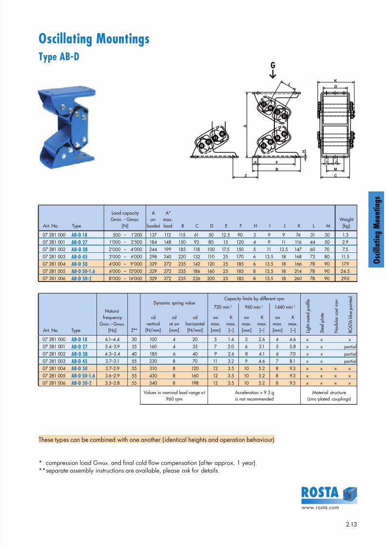
Oscillating MountingsType AB-D
Art. No. Type
Load capacity Gmin. – Gmax.
[N]
A un-
loaded
A*max.load B C D E F H I J K L M
Weight [kg]
07 281 000 AB-D 18 500 – 1’200 137 112 115 61 50 12.5 90 3 9 9 74 31 30 1.3
07 281 001 AB-D 27 1’000 – 2’500 184 148 150 93 80 15 120 4 9 11 116 44 50 2.9
07 281 002 AB-D 38 2’000 – 4’000 244 199 185 118 100 17.5 150 5 11 13.5 147 60 70 7.5
07 281 003 AB-D 45 3’000 – 6’000 298 240 220 132 110 25 170 6 13.5 18 168 73 80 11.5
07 281 004 AB-D 50 4’000 – 9’000 329 272 235 142 120 25 185 6 13.5 18 166 78 90 17.9
07 281 005 AB-D 50-1.6 6’000 – 12’000 329 272 235 186 160 25 185 8 13.5 18 214 78 90 24.5
07 281 006 AB-D 50-2 8’000 – 16’000 329 272 235 226 200 25 185 8 13.5 18 260 78 90 29.0
I
D
K
C
J
H
A
B
L
E F
Z
M
Art. No. Type
Naturalfrequency
Gmin.– Gmax.
[Hz] Z**
Dynamic spring valueCapacity limits by different rpm
720 min-1 960 min-1 1440 min-1
L i g h t m e
t a l
p r o
fi l e
S t e e
l p
l a t e
N o
d u
l a r c a s t
i r o n
R O S T A b l u e p a i n t e d
cd vertical[N/mm]
cdat sw [mm]
cdhorizontal[N/mm]
sw max.[mm]
K max.[–]
sw max.[mm]
K max.[–]
sw max.[mm]
K max.[–]
07 281 000 AB-D 18 6.1–4.4 30 100 4 20 5 1.4 5 2.6 4 4.6 x x x
07 281 001 AB-D 27 5.4–3.9 35 160 4 35 7 2.0 6 3.1 5 5.8 x x partial
07 281 002 AB-D 38 4.3–3.4 40 185 6 40 9 2.6 8 4.1 6 7.0 x x partial
07 281 003 AB-D 45 3.7–3.1 55 230 8 70 11 3.2 9 4.6 7 8.1 x x partial
07 281 004 AB-D 50 3.7–2.9 55 310 8 120 12 3.5 10 5.2 8 9.3 x x x x
07 281 005 AB-D 50-1.6 3.6–2.9 55 430 8 160 12 3.5 10 5.2 8 9.3 x x x x
07 281 006 AB-D 50-2 3.5–2.8 55 540 8 198 12 3.5 10 5.2 8 9.3 x x x x
Values in nominal load range at960 rpm
Acceleration > 9.3 gis not recommended
Material structure(zinc-plated couplings)
These types can be combined with one another ( identical heights and operation behaviour)
* compression load Gmax. and final cold flow compensation (af ter approx. 1 year).** separate assembly instructions are available, please ask for details.
G
8/10/2019 2013 Oscillating Mountings
http://slidepdf.com/reader/full/2013-oscillating-mountings 14/402.14
www.rosta.com
g
g
A
D
B
F
H
E
C
K
M
LZ
M
K L
I
M
K L
I
N
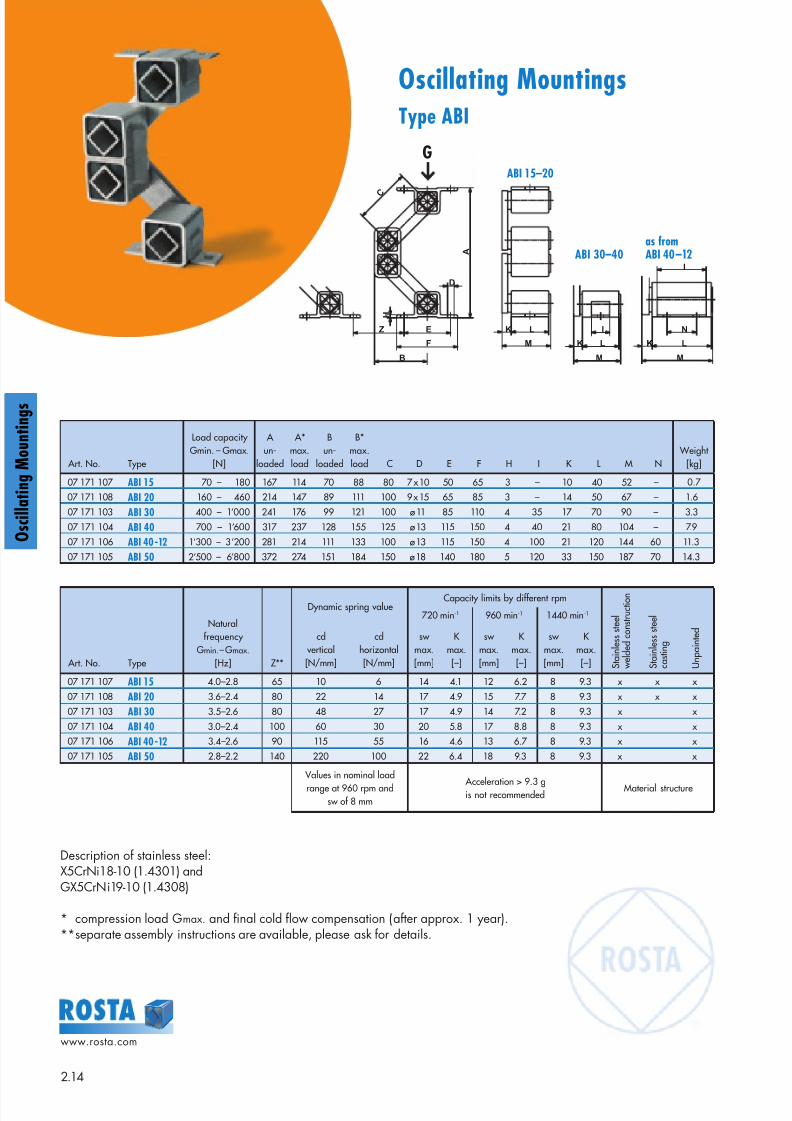
Oscillating MountingsType ABI
Description of stainless steel:X5CrNi18-10 (1.4301) andGX5CrNi19-10 (1.4308)
* compression load Gmax. and final cold flow compensation (after approx. 1 year).** separate assembly instructions are available, please ask for details.
Art. No. Type
Load capacity Gmin. – Gmax.
[N]
A un-
loaded
A*max.load
Bun-
loaded
B*max.load C D E F H I K L M N
Weight [kg]
07 171 107 ABI 15 70 – 180 167 114 70 88 80 7 x 10 50 65 3 – 10 40 52 – 0.7
07 171 108 ABI 20 160 – 460 214 147 89 111 100 9 x 15 65 85 3 – 14 50 67 – 1.6
07 171 103 ABI 30 400 – 1’000 241 176 99 121 100 ø 11 85 110 4 35 17 70 90 – 3.3
07 171 104 ABI 40 700 – 1’600 317 237 128 155 125 ø 13 115 150 4 40 21 80 104 – 7.9
07 171 106 ABI 40-12 1’300 – 3’200 281 214 111 133 100 ø 13 115 150 4 100 21 120 144 60 11.3
07 171 105 ABI 50 2’500 – 6’800 372 274 151 184 150 ø 18 140 180 5 120 33 150 187 70 14.3
Art. No. Type
Naturalfrequency
Gmin.– Gmax.
[Hz] Z**
Dynamic spring valueCapacity limits by different rpm
720 min-1 960 min-1 1440 min-1
S t a i n
l e s s s t e e
l
w e
l d e
d c o n s t r u c t i o n
S t a i n
l e s s s t e e
l
c a s t i n g
U n p a
i n t e
dcd
vertical[N/mm]
cdhorizontal[N/mm]
sw max.[mm]
K max.[–]
sw max.[mm]
K max.[–]
sw max.[mm]
K max.[–]
07 171 107 ABI 15 4.0–2.8 65 10 6 14 4.1 12 6.2 8 9.3 x x x
07 171 108 ABI 20 3.6–2.4 80 22 14 17 4.9 15 7.7 8 9.3 x x x
07 171 103 ABI 30 3.5–2.6 80 48 27 17 4.9 14 7.2 8 9.3 x x
07 171 104 ABI 40 3.0–2.4 100 60 30 20 5.8 17 8.8 8 9.3 x x
07 171 106 ABI 40-12 3.4–2.6 90 115 55 16 4.6 13 6.7 8 9.3 x x
07 171 105 ABI 50 2.8–2.2 140 220 100 22 6.4 18 9.3 8 9.3 x x
Values in nominal loadrange at 960 rpm and
sw of 8 mm Acceleration > 9.3 gis not recommended
Material structure
ABI 15–20
ABI 30–40as fromABI 40–12
G
8/10/2019 2013 Oscillating Mountings
http://slidepdf.com/reader/full/2013-oscillating-mountings 15/402.15
www.rosta.com
O s c i l l a t i n g M o u n t i n g s
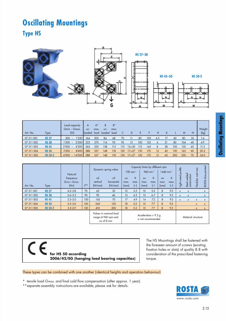
Oscillating MountingsType HS
M
K L
N
M
K L
NN
Z
A
D
B
F
E
M
K L
N
H
C
The HS Mountings shall be fastened withthe foreseen amount of screws (existingfixation holes or slots) of quality 8.8 withconsideration of the prescribed fasteningtorque.
These types can be combined with one another ( identical heights and operation behaviour)
* tensile load Gmax. and final cold flow compensation (after approx. 1 year).** separate assembly instructions are available, please ask for details.
Art. No. Type
Load capacity Gmin. – Gmax.
[N]
A un-
loaded
A*max.load
Bun-
loaded
B*max.load C D E F H K L M N
Weight [kg]
07 311 001 HS 27 500 – 1’250 164 202 84 68 70 11 80 105 4.5 17 60 80 35 1.6
07 311 002 HS 38 1’200 – 2’500 223 275 114 92 95 13 100 125 6 21 80 104 40 4.9
07 311 003 HS 45 2’000 – 4’200 265 325 138 113 110 13 x 20 115 145 8 28 100 132 65 11.3
07 311 004 HS 50 3’500 – 8’400 288 357 148 118 120 17 x 27 130 170 12 40 120 165 60 20.2
07 311 005 HS 50-2 6’000 – 14’000 288 357 148 118 120 17 x 27 130 170 12 45 200 250 70 34.0
Art. No. Type
Naturalfrequency
Gmin.– Gmax.
[Hz] Z**
Dynamic spring value Capacity limits by different rpm720 min-1 960 min-1 1440 min-1
L i g h t m e
t a l
p r o
fi l e
S t e e
l w e
l d e
d
c o n s t r u c
t i o n
N o
d u
l a r c a s t
i r o n
R O S T A b l u e p a i n t e
d
cd vertical[N/mm]
cdhorizontal[N/mm]
sw max.[mm]
K max.[–]
sw max.[mm]
K max.[–]
sw max.[mm]
K max.[–]
07 311 001 HS 27 4.2–3.8 70 65 32 12 3.5 10 5.2 8 9.3 x x x
07 311 002 HS 38 3.6–3.3 90 95 46 15 4.3 13 6.7 8 9.3 x x x
07 311 003 HS 45 3.3–3.0 100 142 70 17 4.9 14 7.2 8 9.3 x x x x
07 311 004 HS 50 3.2–3.0 120 245 120 18 5.2 15 7.7 8 9.3 x x
07 311 005 HS 50-2 3.2–2.9 120 410 200 18 5.2 15 7.7 8 9.3 x x
Values in nominal loadrange at 960 rpm and
sw of 8 mm
Acceleration > 9.3 gis not recommended
Material structure
HS 27–38
HS 45–50 HS 50-2
G
for HS 50 according2006/42/EG (hanging load bearing capacities)
8/10/2019 2013 Oscillating Mountings
http://slidepdf.com/reader/full/2013-oscillating-mountings 16/402.16
www.rosta.com
g
g
~ 4 5
S
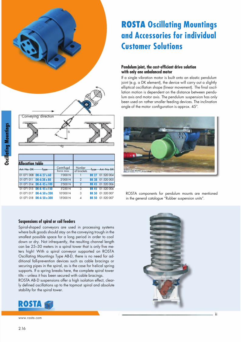
ROSTA Oscillating Mountingsand Accessories for individualCustomer Solutions
Pendulum joint, the cost-efficient drive solutionwith only one unbalanced motorIf a single vibration motor is built onto an elastic pendulumjoint (e.g. a DK element), the device will carry out a slightlyelliptical oscillation shape (linear movement). The final oscil-lation motion is dependent on the distance between pendu-lum axis and motor axis. The pendulum suspension has onlybeen used on rather smaller feeding devices. The inclinationangle of the motor configuration is approx. 45°.
Suspensions of spiral or coil feedersSpiral-shaped conveyors are used in processing systemswhere bulk goods should stay on the conveying trough in the
smallest possible space for a long period in order to cooldown or dry. Not infrequently, the resulting channel lengthcan be 25–30 meters in a spiral tower that is only five me-ters high! With a spiral conveyor supported on ROSTAOscillating Mountings Type AB-D, there is no need for ad-ditional fall-prevention devices such as cable bracings orsecuring pipes in the spiral, as is the case for helical springsupports. If a spring breaks here, the complete spiral towertilts – unless it has been secured with cable bracings.ROSTA AB-D suspensions offer a high isolation effect, clear-ly defined oscillations up to the topmost spiral and absolutestability for the spiral tower.
Art. No. DK Type Centrifugalforce max.
Numberof brackets Type Art. No. BK
01 071 008 DK-A 27 x 60 1’000 N 1 BK 27 01 520 004
01 071 011 DK-A 38 x 80 2’000 N 2 BK 38 01 520 00501 071 014 DK-A 45 x 100 3’500 N 2 BK 45 01 520 006
01 071 015 DK-A 45 x 150 5’250 N 3 BK 45 01 520 006
01 071 017 DK-A 50 x 200 10’000 N 3 BK 50 01 520 007
01 071 018 DK-A 50 x 300 15’000 N 4 BK 50 01 520 007
ROSTA components for pendulum mounts are mentionedin the general catalogue “Rubber suspension units”.
Conveying direction
Allocation table
8/10/2019 2013 Oscillating Mountings
http://slidepdf.com/reader/full/2013-oscillating-mountings 17/402.17
www.rosta.com
O s c i l l a t i n g M o u n t i n g s
30° Conveying direction
m2
m1
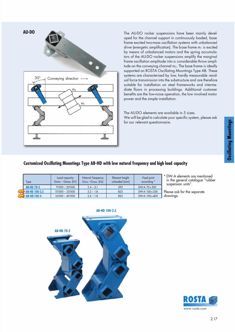
Customized Oscillating Mountings Type AB-HD with low natural frequency and high load capacity
AU-DO The AU-DO rocker suspensions have been mainly devel-oped for the channel support in continuously loaded, baseframe excited two-mass oscillation systems with unbalanceddrive (energetic amplification). The base frame m1 is excitedby means of unbalanced motors and the spring accumula-
tors of the AU-DO rocker suspensions amplify the marginalframe oscillation amplitude into a considerable throw ampli-tude on the conveying channel m2. The base frame is ideallysupported on ROSTA Oscillating Mountings Type AB. Thesesystems are characterised by low, hardly measurable resid-ual force transmission into the substructure and are thereforesuitable for installation on steel frameworks and interme-diate floors in processing buildings. Additional customerbenefits are the low-noise operation, the low involved motorpower and the simple installation.
The AU-DO elements are available in 5 sizes.We will be glad to calculate your specific system, please askfor our relevant questionnaire.
O s c i l l a t i n g M o u n t i n g s
TypeLoad capacity
Gmin. – Gmax. [N]Natural frequency Gmin.– Gmax. [Hz]
Element heightunloaded [mm]
Food printaccording *
* DW-A elements are mentionedin the general catalogue “rubbersuspension units”.
Please ask for the separatedrawings.
AB-HD 70-3 9’000 – 20’000 2.4 – 2.1 592 DW-A 70 x 300
AB-HD 100-2.5 10’000 – 25’000 2.2 – 1.8 823 DW-A 100 x 250
AB-HD 100-4 16’000 – 40’000 2.2 – 1.8 823 DW-A 100 x 400
AB-HD 70-3
AB-HD 100-2.5
n e w
n e w
8/10/2019 2013 Oscillating Mountings
http://slidepdf.com/reader/full/2013-oscillating-mountings 18/402.18
www.rosta.com
g
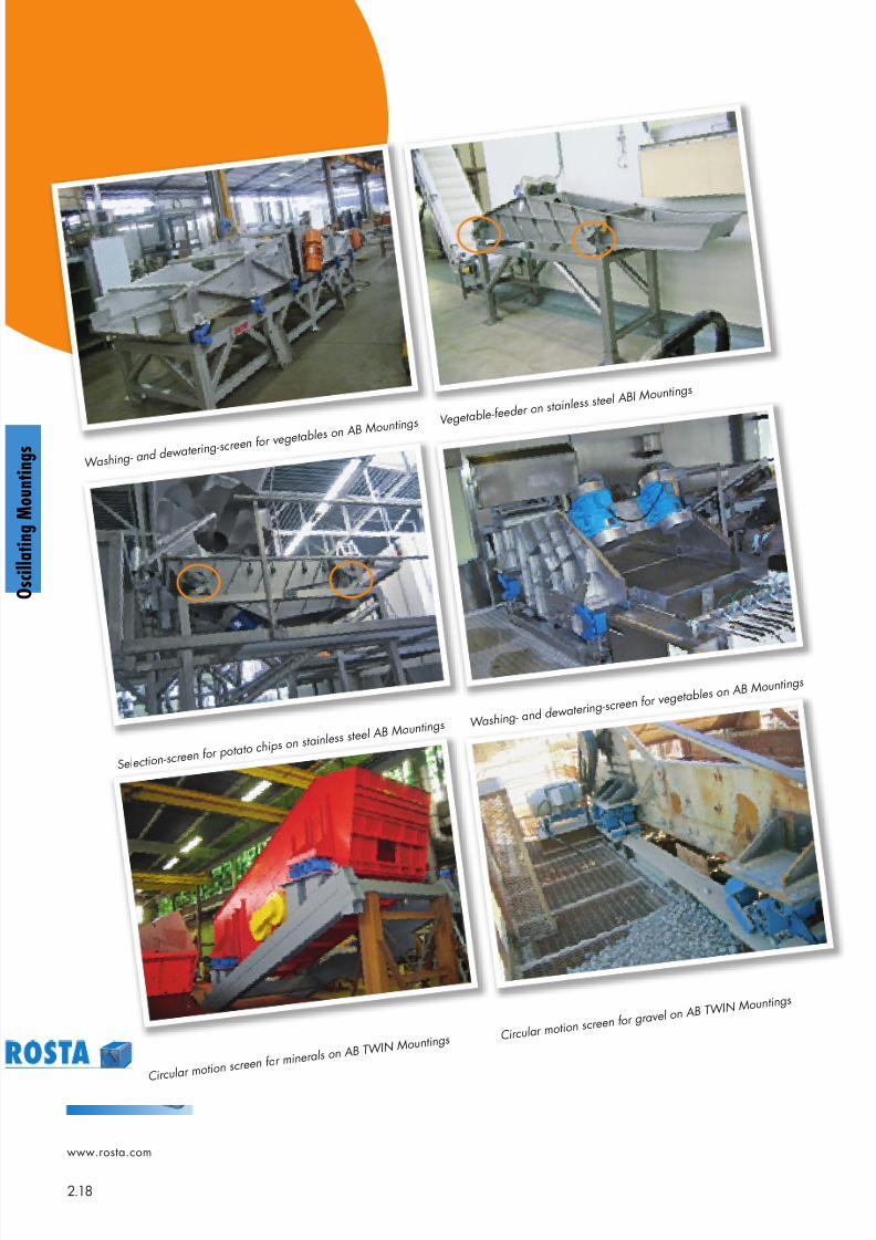
g W ashing- and dew at er ing- sc
r een f or v eget ables on AB Mount ings
Select ion- scr een f or po
t at o chips on st ainless s
t eel AB Mount ings
Cir cular mot ion scr een
f or miner als on AB T W IN Mount ings
V eget able- f eeder on st
ainless st eel ABI Mount ings
W ashing- and dew at er ing- sc
r een f or v eget ables on
AB Mount ings
Cir cular mot ion scr een f or gr av el
on AB T W IN Mount ings
8/10/2019 2013 Oscillating Mountings
http://slidepdf.com/reader/full/2013-oscillating-mountings 19/402.19
www.rosta.com
O s c i l l a t i n g M o u n t i n g s
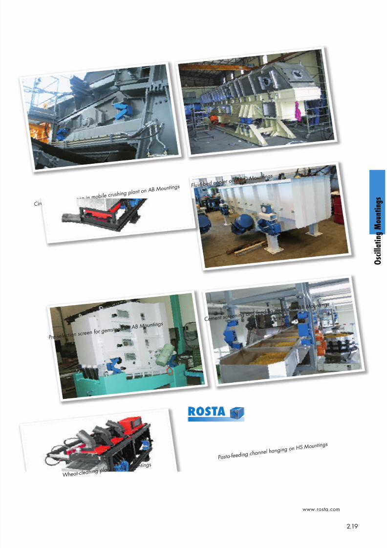
Cir cular mot ion scr een in mobile cr ushing plant on AB Mo
unt ings
Pr e- select ion scr een f or
gemst one on AB Mount ings
W heat - cleaning plant o
n AB Mount ings
Fluid- bed cooler on AB
- D Mount ings
Cement scr eening and f eed
ing dev ice on AB Mount ings
Past a- f eeding channel h
anging on HS Mount ings
8/10/2019 2013 Oscillating Mountings
http://slidepdf.com/reader/full/2013-oscillating-mountings 20/402.20
www.rosta.com
Oscillating shaker conveyors with crank shaft drive are wide-
ly used for the transportation and selection of bulk material.A shaker conveyor consist of a heavy and (infinitely) stiff de-signed shaker and/or screening trough, which is supportedby several pairs of guiding rocker arms. The rocker arms arealso connected with the lower base frame which is anchoredin the building foundation by means of tie bolts. The eccen-tric shaft transmitting the oscillations to the trough is alwaysdriven by elastic belt drive to compensate the hits by thedead centers of the crank shaft drive. A driving rod with anelastic drive head connects the crank drive with the baseframe of the trough and transmits the required oscillations forthe transport of the bulk material on the feeder. According tothe length, stiffness and weight of the shaker trough severalpairs of supporting and guiding rocker arms are requiredbetween base frame and conveyor.
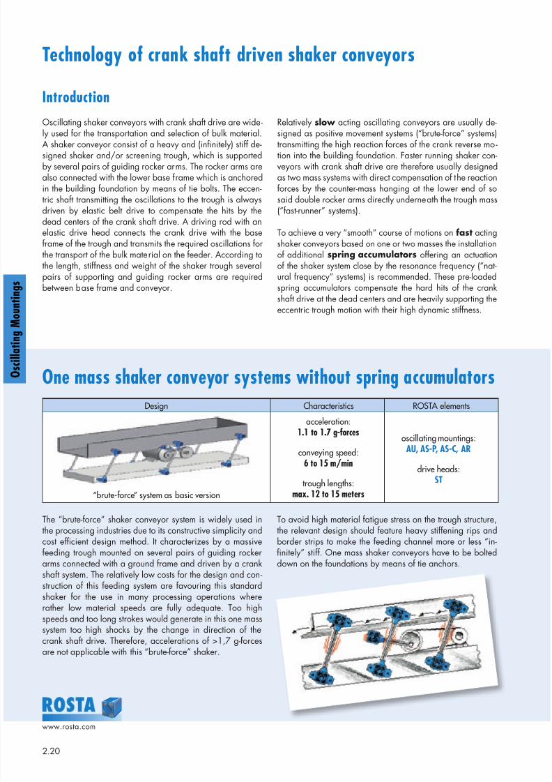
The “brute-force” shaker conveyor system is widely used inthe processing industries due to its constructive simplicity and
cost efficient design method. It characterizes by a massivefeeding trough mounted on several pairs of guiding rockerarms connected with a ground frame and driven by a crankshaft system. The relatively low costs for the design and con-struction of this feeding system are favouring this standardshaker for the use in many processing operations whererather low material speeds are fully adequate. Too highspeeds and too long strokes would generate in this one masssystem too high shocks by the change in direction of thecrank shaft drive. Therefore, accelerations of >1,7 g-forcesare not applicable with this “brute-force” shaker.
To avoid high material fatigue stress on the trough structure,the relevant design should feature heavy stiffening rips and
border strips to make the feeding channel more or less “in-finitely” stiff. One mass shaker conveyors have to be bolteddown on the foundations by means of tie anchors.
Technology of crank shaft driven shaker conveyors
Relatively slow acting oscillating conveyors are usually de-
signed as positive movement systems (“brute-force” systems)transmitting the high reaction forces of the crank reverse mo-tion into the building foundation. Faster running shaker con-veyors with crank shaft drive are therefore usually designedas two mass systems with direct compensation of the reactionforces by the counter-mass hanging at the lower end of sosaid double rocker arms directly underneath the trough mass(“fast-runner” systems).
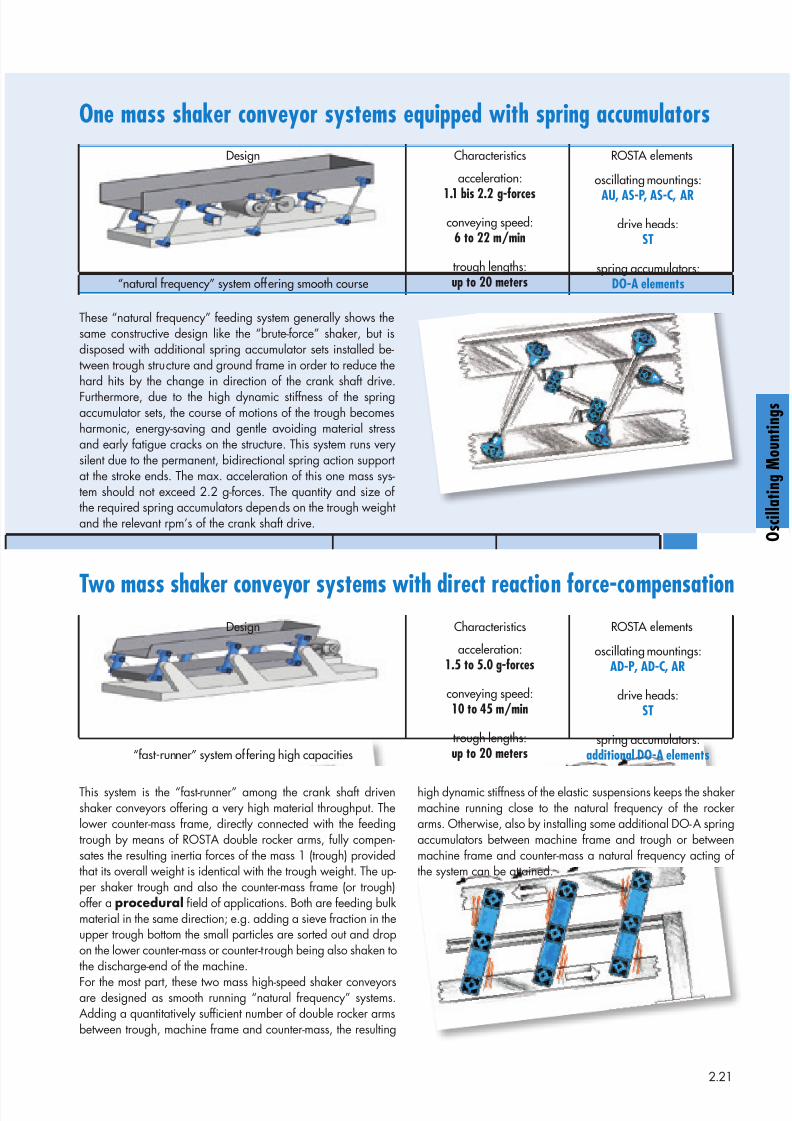
To achieve a very “smooth” course of motions on fast actingshaker conveyors based on one or two masses the installationof additional spring accumulators offering an actuationof the shaker system close by the resonance frequency (“nat-ural frequency” systems) is recommended. These pre-loadedspring accumulators compensate the hard hits of the crankshaft drive at the dead centers and are heavily supporting theeccentric trough motion with their high dynamic stiffness.
One mass shaker conveyor systems without spring accumulators
Design Characteristics ROSTA elements
“brute-force” system as basic version
acceleration:1.1 to 1.7 g-forces
conveying speed:6 to 15 m/min
trough lengths:max. 12 to 15 meters
oscillating mountings:AU, AS-P, AS-C, AR
drive heads:ST
Introduction
g
g
8/10/2019 2013 Oscillating Mountings
http://slidepdf.com/reader/full/2013-oscillating-mountings 21/402.21
These “natural frequency” feeding system generally shows thesame constructive design like the “brute-force” shaker, but isdisposed with additional spring accumulator sets installed be-tween trough structure and ground frame in order to reduce thehard hits by the change in direction of the crank shaft drive.Furthermore, due to the high dynamic stiffness of the springaccumulator sets, the course of motions of the trough becomesharmonic, energy-saving and gentle avoiding material stressand early fatigue cracks on the structure. This system runs verysilent due to the permanent, bidirectional spring action supportat the stroke ends. The max. acceleration of this one mass sys-tem should not exceed 2.2 g-forces. The quantity and size ofthe required spring accumulators depends on the trough weightand the relevant rpm’s of the crank shaft drive.
This system is the “fast-runner” among the crank shaft drivenshaker conveyors offering a very high material throughput. Thelower counter-mass frame, directly connected with the feedingtrough by means of ROSTA double rocker arms, fully compen-sates the resulting inertia forces of the mass 1 (trough) providedthat its overall weight is identical with the trough weight. The up-per shaker trough and also the counter-mass frame (or trough)offer a procedural field of applications. Both are feeding bulkmaterial in the same direction; e.g. adding a sieve fraction in theupper trough bottom the small particles are sorted out and dropon the lower counter-mass or counter-trough being also shaken tothe discharge-end of the machine.
For the most part, these two mass high-speed shaker conveyorsare designed as smooth running “natural frequency” systems.Adding a quantitatively sufficient number of double rocker armsbetween trough, machine frame and counter-mass, the resulting
One mass shaker conveyor systems equipped with spring accumulators
Two mass shaker conveyor systems with direct reaction force-compensation
Design Characteristics ROSTA elements
“natural frequency” system offering smooth course
acceleration:
1.1 bis 2.2 g-forces
conveying speed:6 to 22 m/min
trough lengths:up to 20 meters
oscillating mountings:
AU, AS-P, AS-C, AR
drive heads:ST
spring accumulators:DO-A elements
Design Characteristics ROSTA elements
“fast-runner” system offering high capacities
acceleration:1.5 to 5.0 g-forces
conveying speed:10 to 45 m/min
trough lengths:up to 20 meters
oscillating mountings:AD-P, AD-C, AR
drive heads:ST
spring accumulators:additional DO-A elements
high dynamic stiffness of the elastic suspensions keeps the shakermachine running close to the natural frequency of the rockerarms. Otherwise, also by installing some additional DO-A springaccumulators between machine frame and trough or betweenmachine frame and counter-mass a natural frequency acting ofthe system can be attained.
O s c i l l a t i n g M o u n t i n g s
8/10/2019 2013 Oscillating Mountings
http://slidepdf.com/reader/full/2013-oscillating-mountings 22/402.22
www.rosta.com
g
g
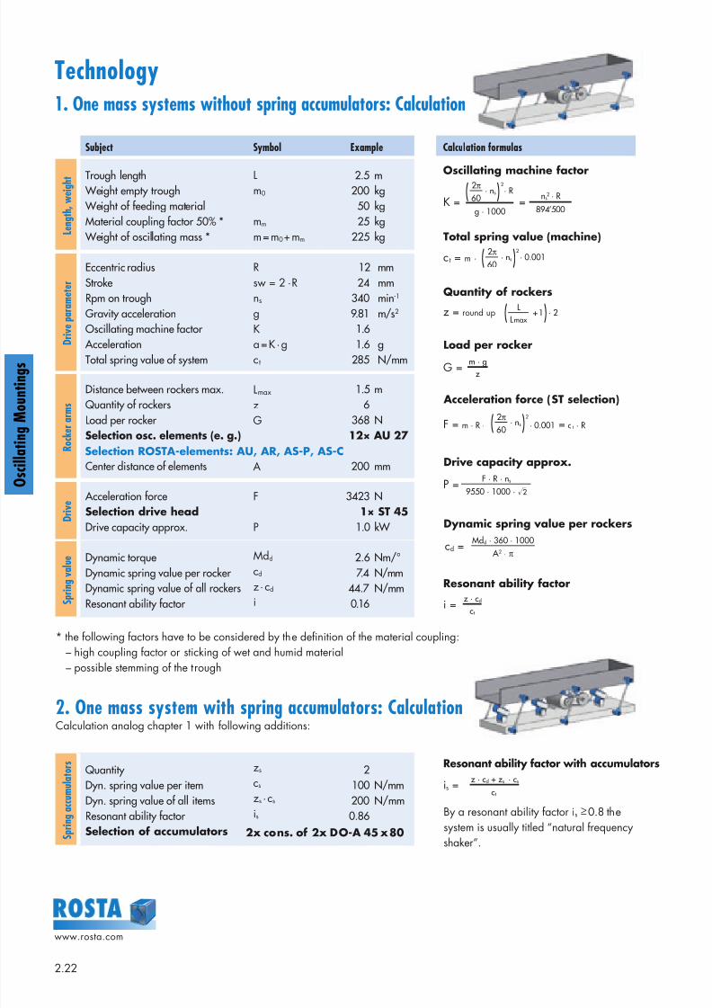
Technology1. One mass systems without spring accumulators: Calculation
Subject Symbol Example Calculation formulas
L e n g t h ,
w e i g h t Trough length
Weight empty trough Weight of feeding material
Material coupling factor 50% * Weight of oscillating mass *
Lm0
mm
m = m0+ mm
2.5 m 200 kg 50 kg
25 kg 225 kg
D r i v e p a r a m e t e r
Eccentric radius
StrokeRpm on trough
Gravity accelerationOscillating machine factor
Acceleration
Total spring value of system
R
sw = 2 · R
ns
g
K
a = K · g
ct
12 mm
24 mm 340 min-1
9.81 m/s2
1.6
1.6 g 285 N/mm
R o c k e r a r m s
Distance between rockers max.Quantity of rockers
Load per rocker Selection osc. elements (e. g.)
Center distance of elements
Lmax
z
G
A
1.5 m 6
368 N12× AU 27
200 mm
D r i v e
Acceleration forceSelection drive head
Drive capacity approx.
F
P
3423 N1× ST 45
1.0 kW
S p r i n g v a l u e Dynamic torque
Dynamic spring value per rocker Dynamic spring value of all rockersResonant ability factor
Mdd
cd
z · cd
i
2.6 Nm/°
7.4 N/mm 44.7 N/mm
0.16
* the following factors have to be considered by the definition of the material coupling:
– high coupling factor or sticking of wet and humid material
– possible stemming of the trough
2. One mass system with spring accumulators: CalculationCalculation analog chapter 1 with following additions:
S p r i n g a c c u m u l a t o r s
Quantity Dyn. spring value per item
Dyn. spring value of all itemsResonant ability factor Selection of accumulators
zs
cs
zs · cs
is
2100 N/mm
200 N/mm 0.86
Selection ROSTA-elements: AU, AR, AS-P, AS-C
2x cons. of 2x DO-A 45 x 80
K = = · ns · R
g · 1000
2π
60 ns2 · R
894’500
( )2Oscillating machine factor
c t = m · · ns · 0.0012π
60( )2
Total spring value (machine)
z = round up · 2+ 1L
L max ( )Quantity of rockers
G =m · g
z
Load per rocker
F = m · R · · 0.001 = c t · R· ns2π
60( )2
Acceleration force (ST selection)
P =F · R · ns
9550 · 1000 ·√2
Drive capacity approx.
cd =Mdd · 360 · 1000
A 2 · π
Dynamic spring value per rockers
i =z · cd
ct
Resonant ability factor
is =z · cd + zs · cs
ct
Resonant ability factor with accumulators
By a resonant ability factor is ≥ 0.8 the
system is usually titled “natural frequency
shaker”.
8/10/2019 2013 Oscillating Mountings
http://slidepdf.com/reader/full/2013-oscillating-mountings 23/40
8/10/2019 2013 Oscillating Mountings
http://slidepdf.com/reader/full/2013-oscillating-mountings 24/402.24
www.rosta.com
g
g
m1
m2
The 9 installation steps for a two mass system with double rocker arms:1. All fixation holes for the rockers in trough, counter-mass and machine frame have to be
drilled very accurately previous the final machine assembling.2. Installation of the middle elements of the rocker arms on the central machine frame, all inclina-
tion angles duly adjusted (e.g. 30°), tightening of the screws with required fastening torque.
3. Lifting of the counter-mass with accurate horizontal alignment until the bores in the counter-massframe stay congruent with the bore holes of the lower element. Jamming of the counter-masswith e.g. wooden chocks.
4. Tightening of the fixation screws on counter-mass with required fastening torque.5. Inserting of the feeding trough into machine frame structure. Accurate horizontal alignment
until the bores in the trough stay congruent with the bore holes of the upper element. Jam-ming of the trough with e.g. wooden chocks.
6. Tightening of the fixation screws on trough with required fastening torque.7. Installation of the driving rod with drive head ST in “neutral” position i.e. eccentric drive
should stay in between the two stroke ends. Length adjustment of the driving rod and tighten-ing of the counternuts.
8. Removal of the jamming chocks under counter-mass and trough.9. Test start of the shaker conveyor.
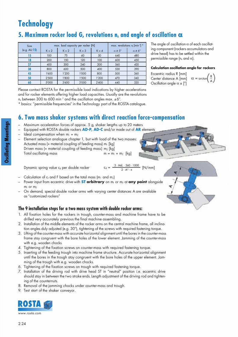
Technology5. Maximum rocker load G, revolutions ns and angle of oscillation α
6. Two mass shaker systems with direct reaction force-compensation– Maximum acceleration forces of approx. 5 g, shaker lengths up to 20 meters– Equipped with ROSTA double rockers AD-P, AD-C and/or made out of AR elements– Ideal compensation when m1 = m2
– Element selection analogue chapter 1, but with load of the two masses:Actuated mass (+ material coupling of feeding mass) m1 [kg] Driven mass (+ material coupling of feeding mass) m2 [kg] Total oscillating mass m = m1 + m2 [kg]
Dynamic spring value cd per double rocker [N/mm]
– Calculation of ct and F based on the total mass (m1 and m2)– Power input from eccentric drive with ST arbitrary on m1 or m2 at any point alongside
m1 or m2
– On demand, special double rocker arms with varying center distances A are availableas “customized rockers”
Size(e.g. AU 15)
max. load capacity per rocker [N] max. revolutions ns [min-1] *
K < 2 K = 2 K = 3 K = 4 α + 5° α + 6°
15 100 75 60 50 640 480
18 200 150 120 100 600 450
27 400 300 240 200 560 420
38 800 600 500 400 530 390
45 1’600 1’200 1’000 800 500 360
50 2’500 1’800 1’500 1’200 470 340
60 5’000 3’600 3’000 2’400 440 320
Please contact ROSTA for the permissible load indications by higher accelerationsand for rocker elements offering higher load capacities. Usually are the revolutionsns between 300 to 600 min -1 and the oscillation angles max. ±6°.* basics: “permissible frequencies” in the Technology part of the ROSTA catalogue.
The angle of oscillation α of each oscillat-ing component (rockers accumulators anddrive head) has to be settled within the
permissible range (ns and α).
Calculation oscillation angle for rockers
Eccentric radius R [mm]Center distance A [mm]Oscillation angle α ± [°]
α = arctan A
R
cd =3 · Mdd · 360 · 1000
2 · A 2 · π
8/10/2019 2013 Oscillating Mountings
http://slidepdf.com/reader/full/2013-oscillating-mountings 25/402.25
www.rosta.com
O s c i l l a t i n g M o u n t i n g s
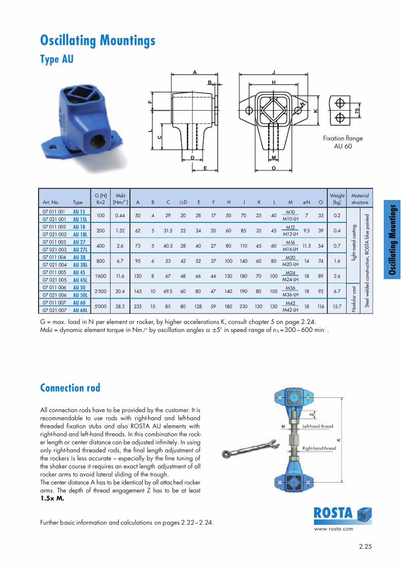
Oscillating MountingsType AU
Art. No. TypeG [N]K<2
Mdd
[Nm/°] A B C D E F H J K L M ø N O Weight
[kg]Materialstructure
07 011 001 AU 15100 0.44 50 4 29 20 28 17 50 70 25 40
M10M10-LH
7 33 0.2
N o
d u l a
r c a s t
l i g h t m e
t a l
c a s t i n g
S t e e l
w e
l d e
d c o n s t r u c
t i o n ,
R O S T A
b l u
e p a
i n t e
d07 021 001 AU 15L
07 011 002 AU 18200 1.32 62 5 31.5 22 34 20 60 85 35 45
M12M12-LH
9.5 39 0.407 021 002 AU 18L
07 011 003 AU 27400 2.6 73 5 40.5 28 40 27 80 110 45 60
M16M16-LH
11.5 54 0.7 07 021 003 AU 27L
07 011 004 AU 38800 6.7 95 6 53 42 52 37 100 140 60 80
M20M20-LH
14 74 1.607 021 004 AU 38L
07 011 005 AU 451’600 11.6 120 8 67 48 66 44 130 180 70 100
M24M24-LH
18 89 2.607 021 005 AU 45L
07 011 006 AU 502’500 20.4 145 10 69.5 60 80 47 140 190 80 105
M36M36-LH
18 93 6.7 07 021 006
AU 50L07 011 007 AU 605’000 38.2 233 15 85 80 128 59 180 230 120 130
M42M42-LH
18 116 15.7 07 021 007 AU 60L
Fixation flangeAU 60
Connection rod
All connection rods have to be provided by the customer. It isrecommendable to use rods with right-hand and left-handthreaded fixation stubs and also ROSTA AU elements withright-hand and left -hand threads. In this combination the rock-er length or center distance can be adjusted infinitely. In usingonly right-hand threaded rods, the final length adjustment ofthe rockers is less accurate – especially by the fine tuning ofthe shaker course it requires an exact length adjustment of allrocker arms to avoid lateral sliding of the trough.The center distance A has to be identical by all attached rockerarms. The depth of thread engagement Z has to be at least
1.5x M.
G = max. load in N per element or rocker, by higher accelerations K, consult chapter 5 on page 2.24.Mdd = dynamic element torque in Nm/° by oscillation angles α ±5° in speed range of nS = 300 – 600 min-1.
Further basic information and calculations on pages 2.22 – 2.24.
B
A
C
L
F
D
E
M
O
K
N
H
J
7 0
Left-hand thread
Right-hand thread
8/10/2019 2013 Oscillating Mountings
http://slidepdf.com/reader/full/2013-oscillating-mountings 26/402.26
www.rosta.com
g
g
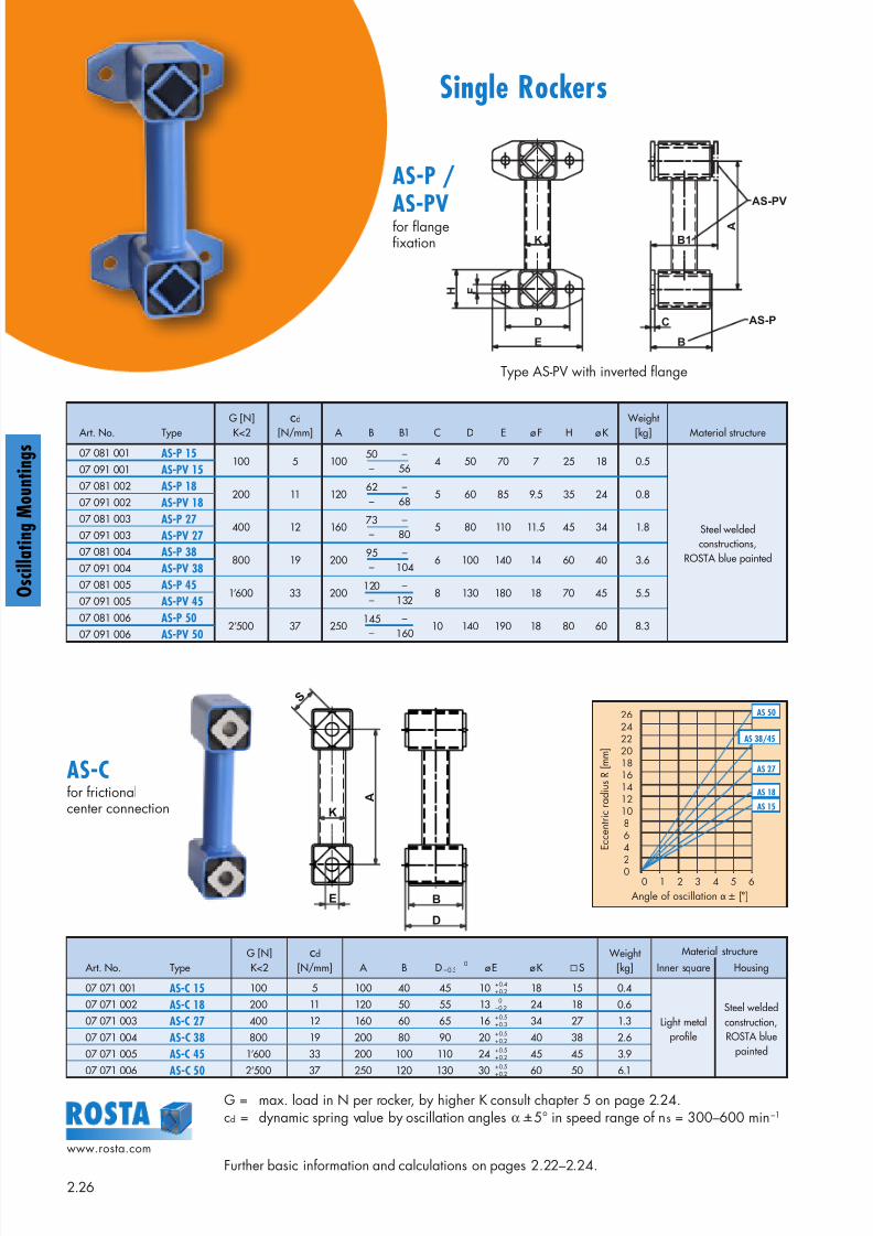
Single Rockers
D
E
C
B
F H
K
A
B1
AS-PV
AS-P
S
E
K
A
B
D
Art. No. Type
G [N]
K<2
cd
[N/mm] A B B1 C D E ø F H ø K
Weight
[kg] Material structure
07 081 001 AS-P 15100 5 100
50–
–56
4 50 70 7 25 18 0.5
Steel weldedconstructions,
ROSTA blue painted
07 091 001 AS-PV 15
07 081 002 AS-P 18200 11 120
62–
–68
5 60 85 9.5 35 24 0.807 091 002 AS-PV 18
07 081 003 AS-P 27400 12 160
73–
–80
5 80 110 11.5 45 34 1.807 091 003 AS-PV 27
07 081 004 AS-P 38800 19 200
95–
–104
6 100 140 14 60 40 3.607 091 004 AS-PV 38
07 081 005 AS-P 451’600 33 200
120–
–132
8 130 180 18 70 45 5.507 091 005 AS-PV 45
07 081 006 AS-P 502’500 37 250
145–
–160
10 140 190 18 80 60 8.307 091 006 AS-PV 50
G = max. load in N per rocker, by higher K consult chapter 5 on page 2.24.cd = dynamic spring value by oscillation angles α +5° in speed range of ns = 300–600 min–1
Further basic information and calculations on pages 2.22–2.24.
AS-P /
AS-PV
AS-C
Art. No. TypeG [N]K<2
cd
[N/mm] A B D – 0.3 ø E ø K S
Weight [kg]
Material structure
Inner square Housing
07 071 001 AS-C 15 100 5 100 40 45 10 + 0.4+ 0.2 18 15 0.4
Light metalprofile
Steel weldedconstruction,ROSTA blue
painted
07 071 002 AS-C 18 200 11 120 50 55 13 0– 0.2 24 18 0.6
07 071 003 AS-C 27 400 12 160 60 65 16 + 0.5+ 0.3 34 27 1.3
07 071 004 AS-C 38 800 19 200 80 90 20 + 0.5+ 0.2 40 38 2.6
07 071 005 AS-C 45 1’600 33 200 100 110 24 + 0.5+ 0.2 45 45 3.9
07 071 006 AS-C 50 2’500 37 250 120 130 30 + 0.5+ 0.2 60 50 6.1
0
Type AS-PV with inverted flange
for flangefixation
for frictionalcenter connection
262422201816141210864
200 1 2 3 4 5 6
E c c e n t r i c r a d i u s R [ m m ]
Angle of oscillation α ± [°]
AS 50
AS 27
AS 18
AS 15
AS 38/45
8/10/2019 2013 Oscillating Mountings
http://slidepdf.com/reader/full/2013-oscillating-mountings 27/402.27
www.rosta.com
O s c i l l a t i n g M o u n t i n g s
S
E
K
A
A
B
D
K
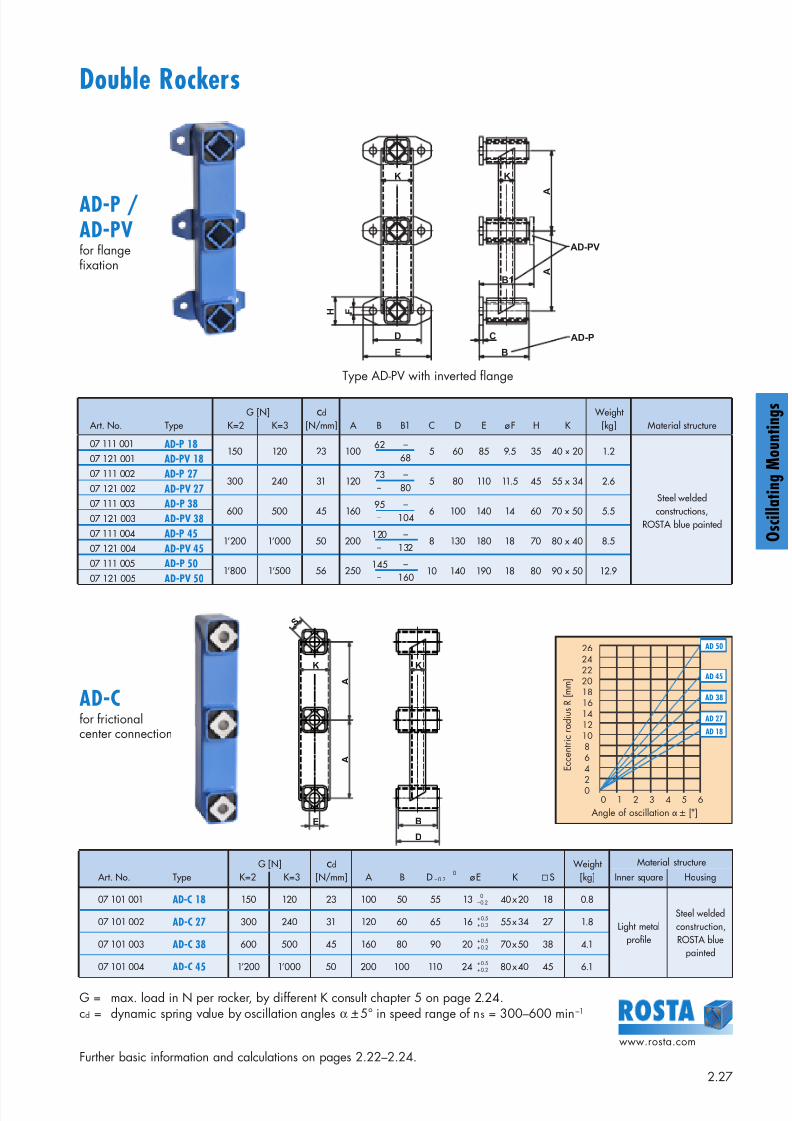
G = max. load in N per rocker, by different K consult chapter 5 on page 2.24.cd = dynamic spring value by oscillation angles α +5° in speed range of ns = 300–600 min–1
Further basic information and calculations on pages 2.22–2.24.
AD-P /AD-PV
AD-C
Double Rockers
K
F H
D
E
K
B1 A
A
C
B
AD-PV
AD-P
Type AD-PV with inverted flange
for flangefixation
for frictionalcenter connection
Art. No. TypeG [N]
K=2 K=3
cd
[N/mm] A B B1 C D E ø F H K Weight
[kg] Material structure
07 111 001 AD-P 18150 120 23 100
62–
–68
5 60 85 9.5 35 40 x 20 1.2
Steel weldedconstructions,
ROSTA blue painted
07 121 001 AD-PV 18
07 111 002 AD-P 27300 240 31 120
73–
–80
5 80 110 11.5 45 55 x 34 2.607 121 002 AD-PV 27
07 111 003 AD-P 38600 500 45 160
95–
–104
6 100 140 14 60 70 x 50 5.507 121 003 AD-PV 38
07 111 004 AD-P 451’200 1’000 50 200
120–
–132
8 130 180 18 70 80 x 40 8.507 121 004 AD-PV 45
07 111 005 AD-P 501’800 1’500 56 250
145–
–160
10 140 190 18 80 90 x 50 12.907 121 005 AD-PV 50
Art. No. TypeG [N]
K=2 K=3cd
[N/mm] A B D – 0.3 ø E K S Weight
[kg]
Material structure
Inner square Housing
07 101 001 AD-C 18 150 120 23 100 50 55 13 0– 0.2 40 x 20 18 0.8
Light metalprofile
Steel weldedconstruction,ROSTA blue
painted
07 101 002 AD-C 27 300 240 31 120 60 65 16 + 0.5+ 0.3 55 x 34 27 1.8
07 101 003 AD-C 38 600 500 45 160 80 90 20 + 0.5+ 0.2 70 x 50 38 4.1
07 101 004 AD-C 45 1’200 1’000 50 200 100 110 24 + 0.5+ 0.2 80 x 40 45 6.1
0
262422201816141210864
200 1 2 3 4 5 6
E c c e n t r i c r a d i u s R [ m m ]
Angle of oscillation α ± [°]
AD 50
AD 38
AD 27
AD 18
AD 45
8/10/2019 2013 Oscillating Mountings
http://slidepdf.com/reader/full/2013-oscillating-mountings 28/402.28
www.rosta.com
g
g
10 – 3 0 °
A
C
S
H
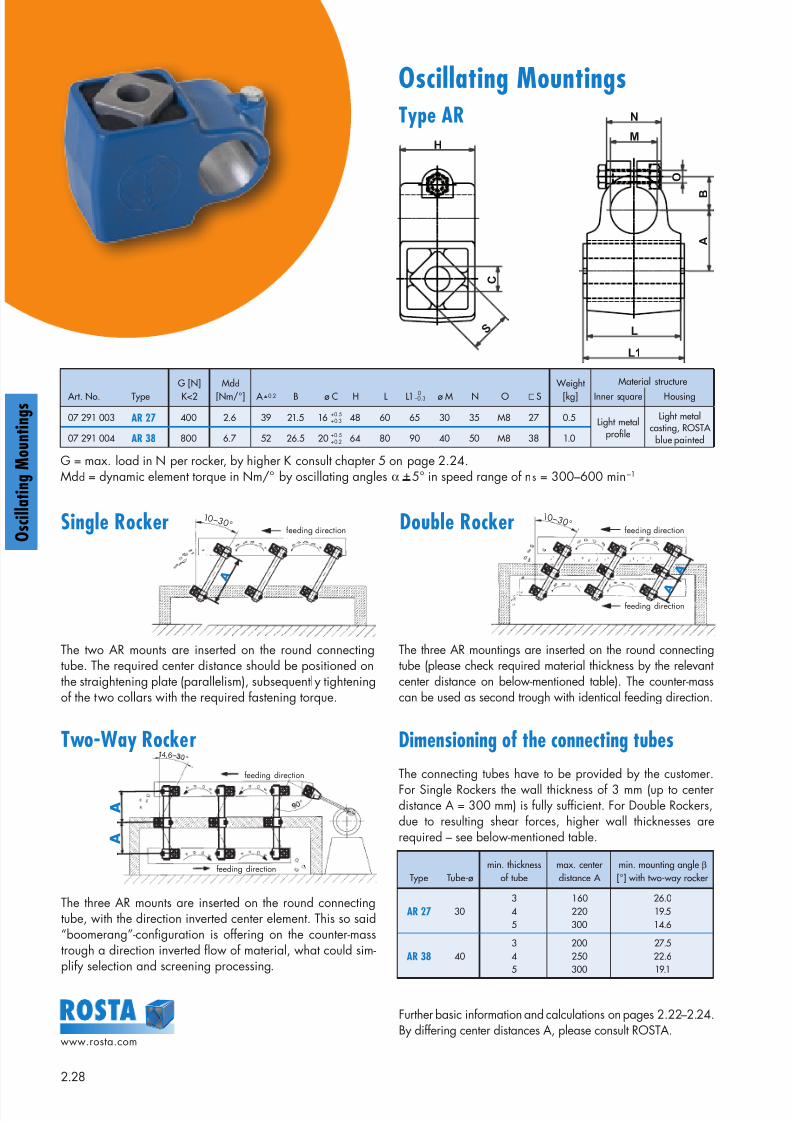
Oscillating MountingsType AR
M
N
O
B
A
L
L1
10 – 3 0 °
feeding direction
A
A
The two AR mounts are inserted on the round connectingtube. The required center distance should be positioned onthe straightening plate (parallelism), subsequently tighteningof the two collars with the required fastening torque.
The three AR mounts are inserted on the round connectingtube, with the direction inverted center element. This so said“boomerang”-configuration is offering on the counter-masstrough a direction inverted flow of material, what could sim-plify selection and screening processing.
Two-Way Rocker
G = max. load in N per rocker, by higher K consult chapter 5 on page 2.24.Mdd = dynamic element torque in Nm/° by oscillating angles α +5° in speed range of ns = 300–600 min–1
Dimensioning of the connecting tubes
The connecting tubes have to be provided by the customer.For Single Rockers the wall thickness of 3 mm (up to centerdistance A = 300 mm) is fully sufficient. For Double Rockers,due to resulting shear forces, higher wall thicknesses arerequired – see below-mentioned table.
Type Tube-ømin. thickness
of tubemax. centerdistance A
min. mounting angle β
[°] with two-way rocker
AR 27 30345
160220300
26.019.514.6
AR 38 40345
200250300
27.522.619.1
Art. No. TypeG [N]K<2
Mdd
[Nm/°] A + 0.2 B ø C H L L1 –0.3 ø M N O S Weight
[kg]
Material structure
Inner square Housing
07 291 003 AR 27 400 2.6 39 21.5 16 48 60 65 30 35 M8 27 0.5 Light metalprofile
Light metalcasting, ROSTA
blue painted07 291 004 AR 38 800 6.7 52 26.5 20 64 80 90 40 50 M8 38 1.0
0
+ 0.5+ 0.3
+ 0.5+ 0.2
The three AR mountings are inserted on the round connectingtube (please check required material thickness by the relevantcenter distance on below-mentioned table). The counter-masscan be used as second trough with identical feeding direction.
Double Rocker
feeding direction
feeding direction
14,6
A
A
Further basic information and calculations on pages 2.22–2.24.By differing center distances A, please consult ROSTA.
Single Rocker feeding direction feeding direction
8/10/2019 2013 Oscillating Mountings
http://slidepdf.com/reader/full/2013-oscillating-mountings 29/40
8/10/2019 2013 Oscillating Mountings
http://slidepdf.com/reader/full/2013-oscillating-mountings 30/40
8/10/2019 2013 Oscillating Mountings
http://slidepdf.com/reader/full/2013-oscillating-mountings 31/402.31
www.rosta.com
O s c i l l a t i n g M o u n t i n g s
ROSTA Oscillating Mountings and Accessories forCustomized Applications
Asymmetrical double rockers for high-speed shaker conveyors
To achieve highest material speed (up to 60 m/min) on shak-er conveyors we recommend the installation of ROSTA doublerocker arms with asymmetrical center distances be-tween the elastic suspensions (ratio 2 : 1). Usually, the eccen-tric drive-input goes on the counter-mass frame which is con-nected to the shorter arm end and therefore weighs 200%of the upper feeding trough. The trough is connected to thelonger arm end of the rocker. That is why it describes thedouble stroke in relation to the counter-mass. This gearratio offers a long material throw on the trough by low reac-tion-force transmittance on the overall machine structure.Please ask for our special application manual asymmetric-al double rockers.
Oversized drive heads for heavy-duty crank shaft driven shaker conveyors
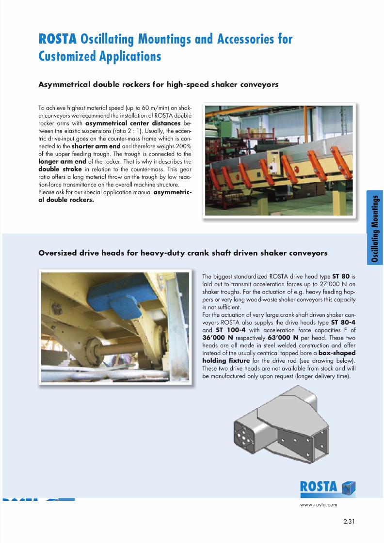
The biggest standardized ROSTA drive head type ST 80 is
laid out to transmit acceleration forces up to 27’000 N onshaker troughs. For the actuation of e.g. heavy feeding hop-pers or very long wood-waste shaker conveyors this capacityis not sufficient.For the actuation of very large crank shaft driven shaker con-veyors ROSTA also supplys the drive heads type ST 80-4 and ST 100-4 with acceleration force capacities F of36’000 N respectively 63’000 N per head. These twoheads are all made in steel welded construction and offerinstead of the usually centrical tapped bore a box-shapedholding fixture for the drive rod (see drawing below).These two drive heads are not available from stock and will
be manufactured only upon request (longer delivery time).
O s c i l l a t i n g M o u n t i n g s
8/10/2019 2013 Oscillating Mountings
http://slidepdf.com/reader/full/2013-oscillating-mountings 32/402.32
www.rosta.com
g
g
ROSTA guiding rods for “Flip-Flow” two mass shaker systems
ROSTA Oscillating Mountingsand Accessories for Customized Applications
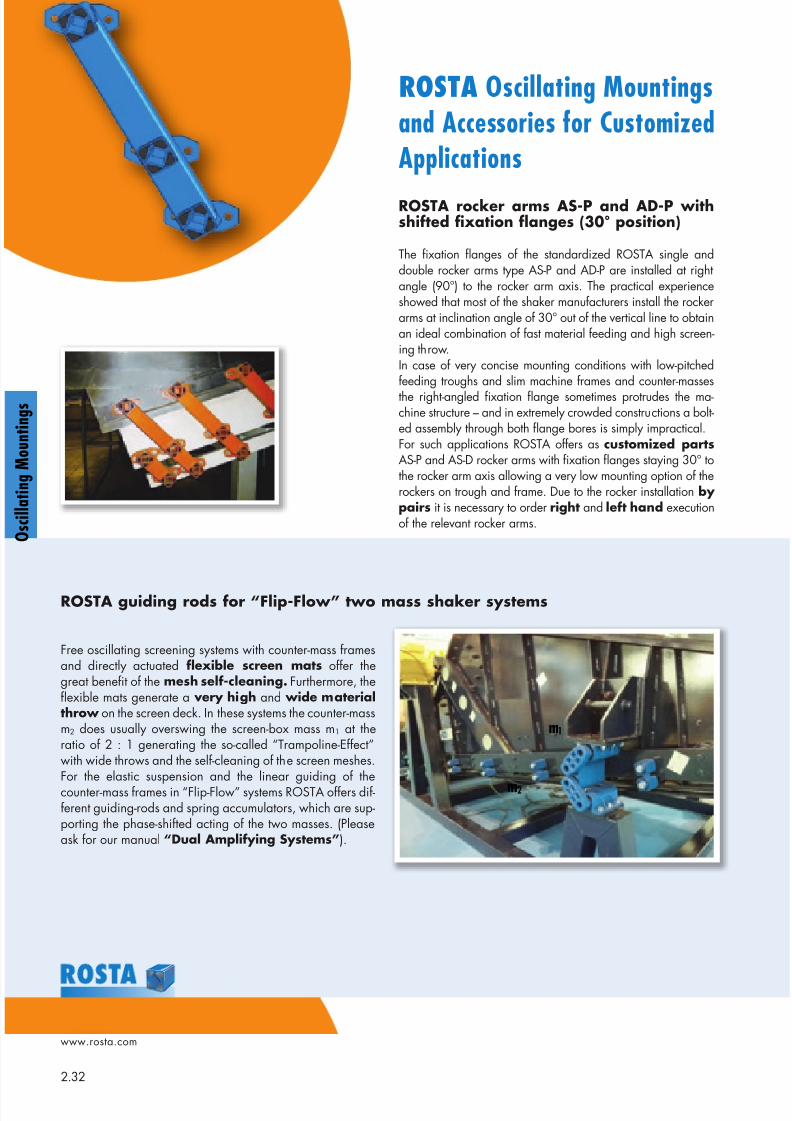
Free oscillating screening systems with counter-mass framesand directly actuated flexible screen mats offer thegreat benefit of the mesh self-cleaning. Furthermore, theflexible mats generate a very high and wide materialthrow on the screen deck. In these systems the counter-massm2 does usually overswing the screen-box mass m1 at theratio of 2 : 1 generating the so-called “Trampoline-Effect”with wide throws and the self-cleaning of the screen meshes.
For the elastic suspension and the linear guiding of thecounter-mass frames in “Flip-Flow” systems ROSTA offers dif-ferent guiding-rods and spring accumulators, which are sup-porting the phase-shifted acting of the two masses. (Pleaseask for our manual “Dual Amplifying Systems”).
ROSTA rocker arms AS-P and AD-P withshifted fixation flanges (30° position)
The fixation flanges of the standardized ROSTA single anddouble rocker arms type AS-P and AD-P are installed at rightangle (90°) to the rocker arm axis. The practical experienceshowed that most of the shaker manufacturers install the rockerarms at inclination angle of 30° out of the vertical line to obtainan ideal combination of fast material feeding and high screen-ing throw.In case of very concise mounting conditions with low-pitchedfeeding troughs and slim machine frames and counter-massesthe right-angled fixation flange sometimes protrudes the ma-chine structure – and in extremely crowded constructions a bolt-ed assembly through both flange bores is simply impractical.For such applications ROSTA offers as customized partsAS-P and AS-D rocker arms with fixation flanges staying 30° tothe rocker arm axis allowing a very low mounting option of therockers on trough and frame. Due to the rocker installation bypairs it is necessary to order right and left hand executionof the relevant rocker arms.
m2
m1
8/10/2019 2013 Oscillating Mountings
http://slidepdf.com/reader/full/2013-oscillating-mountings 33/402.33
www.rosta.com
O s c i l l a t i n g M o u n t i n g s
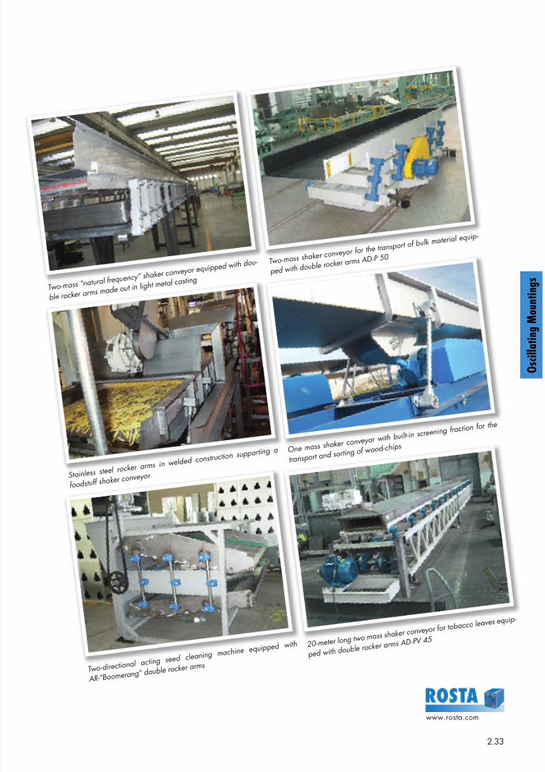
T w o- mass “nat ur al f r equency
” shaker conv ey or equipped w it h dou-
ble r ocker ar ms made out in l
ight met al cast ing
St ainless st eel r ocker
ar ms in w elded const r uct ion s
uppor t ing a
f oodst uf f shaker conv ey
or
T w o- dir ect ional act ing
seed cleaning machine equipped w it h
AR- ”Boomer ang” double r ocker ar m
s
T w o- mass shaker conv ey or f o
r t he t r anspor t of bulk
mat er ial equip-
ped w it h double r ocker ar m
s AD- P 50
One mass shaker conv ey or w it h built - in
scr eening f r act ion f or
t he
t r anspor t and sor t ing of
w ood- chips
20- met er long t w o mass shaker conv ey or f or
t obacco leav es equip-
ped w it h double r ocker ar m
s AD- PV 45
8/10/2019 2013 Oscillating Mountings
http://slidepdf.com/reader/full/2013-oscillating-mountings 34/402.34
www.rosta.com
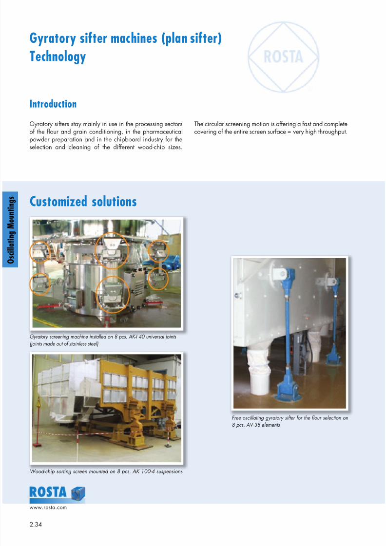
Introduction
Gyratory sifters stay mainly in use in the processing sectorsof the flour and grain conditioning, in the pharmaceuticalpowder preparation and in the chipboard industry for theselection and cleaning of the different wood-chip sizes.
Gyratory sifter machines (plan sifter)
Technology
Customized solutions
Gyratory screening machine installed on 8 pcs. AK-I 40 universal joints
(joints made out of stainless steel)
Wood-chip sorting screen mounted on 8 pcs. AK 100-4 suspensions
Free oscillating gyratory sifter for the flour selection on8 pcs. AV 38 elements
The circular screening motion is offering a fast and completecovering of the entire screen surface = very high throughput.
g
g
8/10/2019 2013 Oscillating Mountings
http://slidepdf.com/reader/full/2013-oscillating-mountings 35/402.35
www.rosta.com
O s c i l l a t i n g M o u n t i n g s
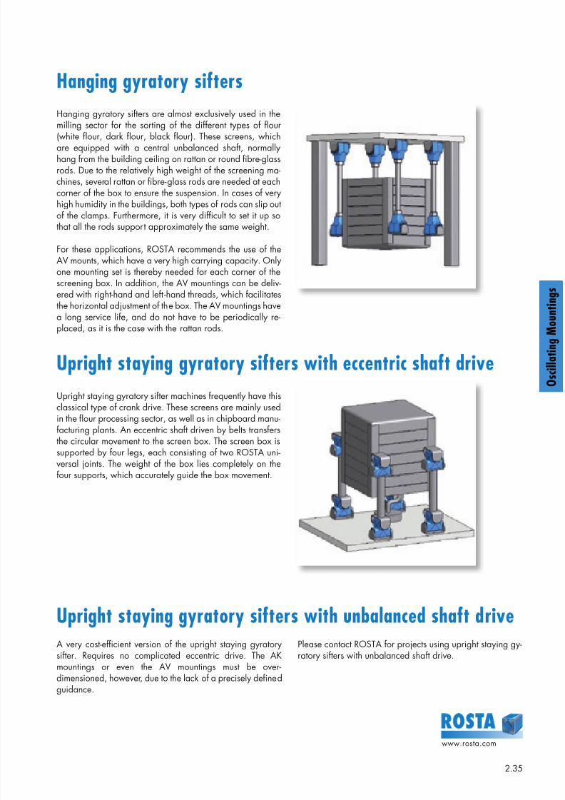
Hanging gyratory sifters
Hanging gyratory sifters are almost exclusively used in themilling sector for the sorting of the different types of flour
(white flour, dark flour, black flour). These screens, whichare equipped with a central unbalanced shaft, normallyhang from the building ceiling on rattan or round fibre-glassrods. Due to the relatively high weight of the screening ma-chines, several rattan or fibre-glass rods are needed at eachcorner of the box to ensure the suspension. In cases of veryhigh humidity in the buildings, both types of rods can slip outof the clamps. Furthermore, it is very difficult to set it up sothat all the rods support approximately the same weight.
For these applications, ROSTA recommends the use of theAV mounts, which have a very high carrying capacity. Onlyone mounting set is thereby needed for each corner of thescreening box. In addition, the AV mountings can be deliv-ered with right-hand and left -hand threads, which facilitatesthe horizontal adjustment of the box. The AV mountings havea long service life, and do not have to be periodically re-placed, as it is the case with the rattan rods.
Upright staying gyratory sifters with eccentric shaft drive
Upright staying gyratory sifters with unbalanced shaft drive
Upright staying gyratory sifter machines frequently have thisclassical type of crank drive. These screens are mainly used
in the flour processing sector, as well as in chipboard manu-facturing plants. An eccentric shaft driven by belts transfersthe circular movement to the screen box. The screen box issupported by four legs, each consisting of two ROSTA uni-versal joints. The weight of the box lies completely on thefour supports, which accurately guide the box movement.
A very cost-efficient version of the upright staying gyratorysifter. Requires no complicated eccentric drive. The AKmountings or even the AV mountings must be over-dimensioned, however, due to the lack of a precisely definedguidance.
Please contact ROSTA for projects using upright staying gy-ratory sifters with unbalanced shaft drive.
8/10/2019 2013 Oscillating Mountings
http://slidepdf.com/reader/full/2013-oscillating-mountings 36/402.36
www.rosta.com
g
g
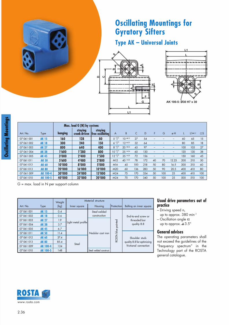
Oscillating Mountings forGyratory SiftersType AK – Universal Joints
S
D C
F
G
L
L1
A
B
A
H A B
S
L
L1
AK 100-5: Ø30 H7 x 30
Art. No. Type Weight
[kg]
Material structure
Bolting on inner squareInner square Housing Protection
07 061 001 AK 15 0.4
Light metal profile
Steel weldedconstruction
R O S T A
b l u
e p
a i n t e
d
End-to-end screw orthreaded barquality 8.8
07 061 002 AK 18 0.6
07 061 003 AK 27 1.9
Nodular cast iron
07 061 004 AK 38 3.7
07 061 005 AK 45 6.7
07 061 011 AK 50 11.4
Shoulder studsquality 8.8 for optimizing
frictional connection
07 061 012 AK 60 37.4
Steel07 061 013 AK 80 85.4
07 061 009 AK 100-4 124
07 061 010 AK 100-5 148 Steel welded construct.
Art. No. Type
Max. load G [N] by system:
A B C D F G ø H L L1+0.2 Shangingstaying
crank drivenstaying
free oscillating
07 061 001 AK 15 160 128 80 5 + 0.5 10 + 0.2 27 54 – – – 60 65 15
07 061 002 AK 18 300 240 150 6 + 0.5 12 + 0.3 32 64 – – – 80 85 18
07 061 003 AK 27 800 640 400 8 + 0.5 20 + 0.4 45 97 – – – 100 105 27
07 061 004 AK 38 1’600 1’280 800 10 + 0.5 25 + 0.4 60 130 – – – 120 130 38
07 061 005 AK 45 3’000 2’400 1’500 12 + 0.5 35 + 0.5 72 156 – – – 150 160 45
07 061 011 AK 50 5’600 4’480 2’800 M12 40 + 0.5 78 172 40 70 12.25 200 210 50
07 061 012 AK 60 10’000 8’000 5’000 M16 45 100 218 50 80 16.5 300 310 60
07 061 013 AK 80 20’000 16’000 10’000 M20 60 136 283 50 90 20.5 400 410 8007 061 009 AK 100-4 30’000 24’000 15’000 M24 75 170 354 50 100 25 400 410 100
07 061 010 AK 100-5 40’000 32’000 20’000 M24 75 170 340 50 100 25 500 510 100
0
0
0
0
0
G = max. load in N per support column
Usual drive parameters out ofpractice– Driving speed ns
up to approx. 380 min -1
– Oscillation angle αup to approx. + 3.5°
General advisesThe operating parameters shallnot exceed the guidelines of the“frequency spectrum” in theTechnology part of the ROSTAgeneral catalogue.
8/10/2019 2013 Oscillating Mountings
http://slidepdf.com/reader/full/2013-oscillating-mountings 37/402.37
www.rosta.com
O s c i l l a t i n g M o u n t i n g s
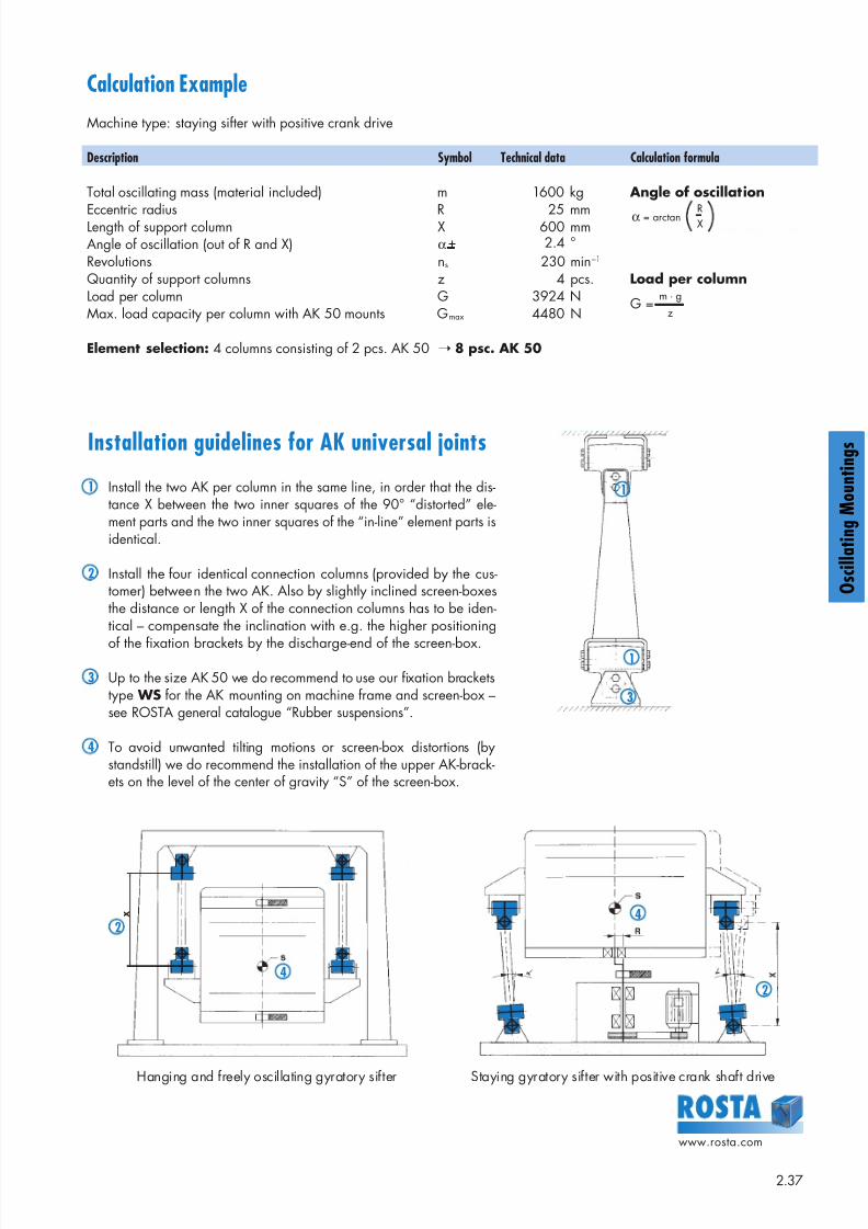
Calculation Example
Machine type: staying sifter with positive crank drive
Description Symbol Technical data Calculation formula
Total oscillating mass (material included) m 1600 kg Angle of oscillation
Eccentric radius R 25 mmLength of support column X 600 mmAngle of oscillation (out of R and X) α + 2.4 °
Revolutions ns 230 min–1
Quantity of support columns z 4 pcs. Load per columnLoad per column G 3924 NMax. load capacity per column with AK 50 mounts Gmax 4480 N
Element selection: 4 columns consisting of 2 pcs. AK 50 ➝ 8 psc. AK 50
Hanging and freely oscillating gyratory sifter Staying gyratory sifter with positive crank shaft drive
Installation guidelines for AK universal joints
1 Install the two AK per column in the same line, in order that the dis-tance X between the two inner squares of the 90° “distorted” ele-ment parts and the two inner squares of the “in-line” element parts isidentical.
2 Install the four identical connection columns (provided by the cus-tomer) between the two AK. Also by slightly inclined screen-boxesthe distance or length X of the connection columns has to be iden-tical – compensate the inclination with e.g. the higher positioning
of the fixation brackets by the discharge-end of the screen-box.
3 Up to the size AK 50 we do recommend to use our fixation bracketstype WS for the AK mounting on machine frame and screen-box –see ROSTA general catalogue “Rubber suspensions”.
4 To avoid unwanted tilting motions or screen-box distortions (bystandstill) we do recommend the installation of the upper AK-brack-ets on the level of the center of gravity “S” of the screen-box.
1
1
3
X 42
2
4
α = arctan RX
G =m · g
z
8/10/2019 2013 Oscillating Mountings
http://slidepdf.com/reader/full/2013-oscillating-mountings 38/402.38
www.rosta.com
g
g
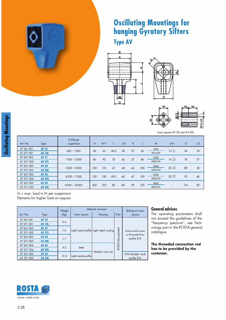
Oscillating Mountings forhanging Gyratory SiftersType AV
Art. No. TypeG [N] persuspension A B +0.2 C D H L M ø N O S
07 261 001 AV 18600 – 1’600 60 65 40.5 28 27 60
M16M16-LH
13 – 0.2 54 1807 271 001 AV 18L
07 261 002 AV 271’300 – 3’000 80 90 53 42 37 80
M20M20-LH
16 + 0.3 74 27 07 271 002 AV 27L
07 261 003AV 38 2’600 – 5’000 100 110 67 48 44 100 M24M24-LH 20 + 0.2 89 3807 271 003 AV 38L
07 261 004 AV 404’500 – 7’500 120 130 69.5 60 47 105
M36M36-LH
20 + 0.2 93 4007 271 004 AV 40L
07 261 005 AV 506’000 – 16’000 200 210 85 80 59 130
M42M42-LH
– 116 5007 271 005 AV 50L
0
+ 0.5
+ 0.5
+ 0.5
Art. No. Type Weight
[kg]
Material structureBolting on inner
squareInner square Housing Prot.
07 261 001 AV 180.4
Light metal profile Light metal casting
R O S T A
b l u
e p a
i n t e
d
End-to-end screwor threaded bar
quality 8.8.
07 271 001 AV 18L07 261 002 AV 27
1.007 271 002 AV 27L
07 261 003 AV 381.7
07 271 003 AV 38L
07 261 004 AV 404.5 Steel
Nodular cast iron07 271 004 AV 40L
07 261 005 AV 5012.3 Light metal profile
M12 shoulder studsquality 8.8.07 271 005 AV 50L
General advisesThe operating parameters shallnot exceed the guidelines of the
“frequency spectrum”, see Tech-nology part in the ROSTA generalcatalogue.
The threaded connection rodhas to be provided by thecustomer.
G = max. load in N per suspensionElements for higher load on request
M
C
D
L
H
A
B
S
O
N
Inner square AV 50 and AV 50L
40 40
M 1 2
30
4 0
Ø 1 2 . 2
5
8/10/2019 2013 Oscillating Mountings
http://slidepdf.com/reader/full/2013-oscillating-mountings 39/402.39
www.rosta.com
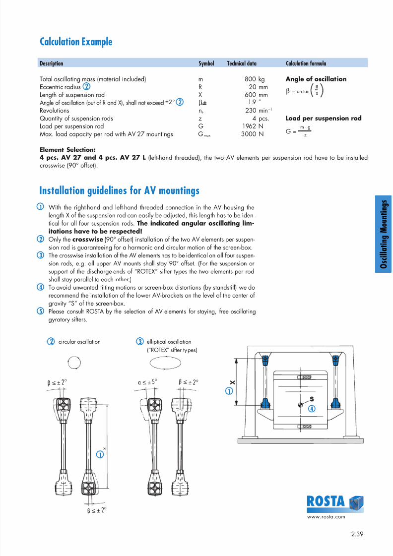
O s c i l l a t i n g M o u n t i n g sInstallation guidelines for AV mountings
1 With the right-hand and left-hand threaded connection in the AV housing thelength X of the suspension rod can easily be adjusted, this length has to be iden-tical for all four suspension rods. The indicated angular oscillating lim-itations have to be respected!
2 Only the crosswise (90° offset) installation of the two AV elements per suspen-sion rod is guaranteeing for a harmonic and circular motion of the screen-box.
3 The crosswise installation of the AV elements has to be identical on all four suspen-sion rods, e.g. all upper AV mounts shall stay 90° offset. (For the suspension orsupport of the discharge-ends of “ROTEX” sifter types the two elements per rodshall stay parallel to each other.)
4 To avoid unwanted tilting motions or screen-box distortions (by standstill) we dorecommend the installation of the lower AV-brackets on the level of the center ofgravity “S” of the screen-box.
5 Please consult ROSTA by the selection of AV elements for staying, free oscillatinggyratory sifters.
β ≤ ± 2°
X
β ≤ ± 2°
β ≤ ± 2° α ≤ ± 5°
1
Calculation Example
Description Symbol Technical data Calculation formula
Total oscillating mass (material included) m 800 kg Angle of oscillationEccentric radius 2 R 20 mm
Length of suspension rod X 600 mmAngle of oscillation (out of R and X), shall not exceed ±2 ° 2 β + 1.9 °
Revolutions ns 230 min–1
Quantity of suspension rods z 4 pcs. Load per suspension rodLoad per suspension rod G 1962 NMax. load capacity per rod with AV 27 mountings Gmax 3000 N
Element Selection: 4 pcs. AV 27 and 4 pcs. AV 27 L (left-hand threaded), the two AV elements per suspension rod have to be installedcrosswise (90° offset).
β = arctanR
X
G =m · g
z
2 circular oscillation
3 elliptical oscillation
(“ROTEX” sifter types)
X
4
1
8/10/2019 2013 Oscillating Mountings
http://slidepdf.com/reader/full/2013-oscillating-mountings 40/40
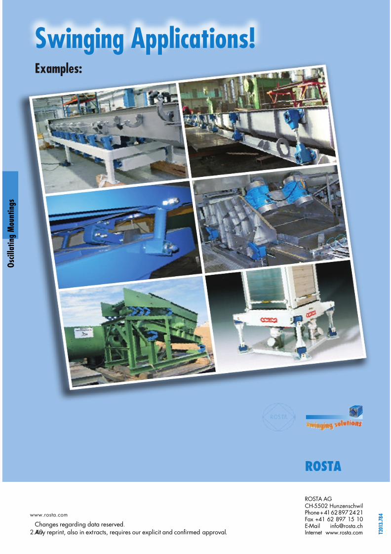
Swinging Applications!Examples:
ROSTA
g
g


