1 ArevaEPRDCPEm Resource From: WILLIFORD Dennis (AREVA) [[email protected]] Sent: Saturday, May 04, 2013 10:49 PM To: Snyder, Amy Cc: Ford, Tanya; ANDERSON Katherine (EXTERNAL AREVA); DELANO Karen (AREVA); LEIGHLITER John (AREVA); ROMINE Judy (AREVA); RYAN Tom (AREVA); LENTZ Tony (EXTERNAL AREVA); STACK Tim (AREVA); DELRUE Joe (AREVA); VANCE Brian (AREVA); GUCWA Len (EXTERNAL AREVA); ELLIOTT Gayle (AREVA); BREMER Ross (EXTERNAL AREVA); WEISS Robert (EXTERNAL AREVA) Subject: Submittal of ANP-10329, "U.S. EPR Mitigation Strategies for Extended Loss of AC Power Event Technical Report" Attachments: nrc13020.pdf; ANP-10329 Rev 0.pdf Amy, AREVA NP Inc. letter NRC:13:020 dated May 4, 2013 (attached) transmitted to NRC Technical Report ANP- 10329, " U.S. EPR Mitigation Strategies for Extended Loss of AC Power Event Technical Report". In RAI 563, the NRC provided a request for additional information regarding the U.S. EPR Design Certification application as it relates to implementation of the Fukushima Near-Term task Force Recommendations, as presented in SECY-12-0025, “Proposed Orders and Requests for Information in Response to Lessons Learned from Japan’s March 11, 2011, Great Tohoku Earthquake and Tsunami”, dated February 12, 2012. This RAI specifically addresses Recommendation 4.2 on Mitigating Strategies. Enclosed with the letter (and attached to this e-mail) is the document ANP-10329, "U.S. EPR Mitigation Strategies for Extended Loss of AC Power Event Technical Report," containing detailed information in support of AREVA NP Inc.’s (AREVA NP) response to this request. AREVA NP has incorporated this report by reference in the U.S. EPR Final Safety Analysis Report (FSAR). The conforming changes to the U.S. EPR FSAR will be included with AREVA NP’s response to RAI 563. AREVA NP requests that the NRC incorporate the review of this report into the assessment of the safety evaluation report for the U.S. EPR FSAR in a manner consistent with other reports which are incorporated by reference in the U.S. EPR FSAR. Sincerely, Dennis Williford, P.E. U.S. EPR Design Certification Licensing Manager AREVA NP Inc. 7207 IBM Drive, Mail Code CLT 2B Charlotte, NC 28262 Phone: 704-805-2223 Email: [email protected]
Transcript
1
ArevaEPRDCPEm Resource
From: WILLIFORD Dennis (AREVA) [[email protected]]Sent: Saturday, May 04, 2013 10:49 PMTo: Snyder, AmyCc: Ford, Tanya; ANDERSON Katherine (EXTERNAL AREVA); DELANO Karen (AREVA);
LEIGHLITER John (AREVA); ROMINE Judy (AREVA); RYAN Tom (AREVA); LENTZ Tony (EXTERNAL AREVA); STACK Tim (AREVA); DELRUE Joe (AREVA); VANCE Brian (AREVA); GUCWA Len (EXTERNAL AREVA); ELLIOTT Gayle (AREVA); BREMER Ross (EXTERNAL AREVA); WEISS Robert (EXTERNAL AREVA)
Subject: Submittal of ANP-10329, "U.S. EPR Mitigation Strategies for Extended Loss of AC Power Event Technical Report"
Attachments: nrc13020.pdf; ANP-10329 Rev 0.pdf
Amy, AREVA NP Inc. letter NRC:13:020 dated May 4, 2013 (attached) transmitted to NRC Technical Report ANP-10329, " U.S. EPR Mitigation Strategies for Extended Loss of AC Power Event Technical Report". In RAI 563, the NRC provided a request for additional information regarding the U.S. EPR Design Certification application as it relates to implementation of the Fukushima Near-Term task Force Recommendations, as presented in SECY-12-0025, “Proposed Orders and Requests for Information in Response to Lessons Learned from Japan’s March 11, 2011, Great Tohoku Earthquake and Tsunami”, dated February 12, 2012. This RAI specifically addresses Recommendation 4.2 on Mitigating Strategies. Enclosed with the letter (and attached to this e-mail) is the document ANP-10329, "U.S. EPR Mitigation Strategies for Extended Loss of AC Power Event Technical Report," containing detailed information in support of AREVA NP Inc.’s (AREVA NP) response to this request. AREVA NP has incorporated this report by reference in the U.S. EPR Final Safety Analysis Report (FSAR). The conforming changes to the U.S. EPR FSAR will be included with AREVA NP’s response to RAI 563. AREVA NP requests that the NRC incorporate the review of this report into the assessment of the safety evaluation report for the U.S. EPR FSAR in a manner consistent with other reports which are incorporated by reference in the U.S. EPR FSAR. Sincerely, Dennis Williford, P.E. U.S. EPR Design Certification Licensing Manager AREVA NP Inc. 7207 IBM Drive, Mail Code CLT 2B Charlotte, NC 28262 Phone: 704-805-2223 Email: [email protected]
Hearing Identifier: AREVA_EPR_DC_RAIs Email Number: 4424 Mail Envelope Properties (554210743EFE354B8D5741BEB695E656154522) Subject: Submittal of ANP-10329, "U.S. EPR Mitigation Strategies for Extended Loss of AC Power Event Technical Report" Sent Date: 5/4/2013 10:49:07 PM Received Date: 5/4/2013 10:50:38 PM From: WILLIFORD Dennis (AREVA) Created By: [email protected] Recipients: "Ford, Tanya" <[email protected]> Tracking Status: None "ANDERSON Katherine (EXTERNAL AREVA)" <[email protected]> Tracking Status: None "DELANO Karen (AREVA)" <[email protected]> Tracking Status: None "LEIGHLITER John (AREVA)" <[email protected]> Tracking Status: None "ROMINE Judy (AREVA)" <[email protected]> Tracking Status: None "RYAN Tom (AREVA)" <[email protected]> Tracking Status: None "LENTZ Tony (EXTERNAL AREVA)" <[email protected]> Tracking Status: None "STACK Tim (AREVA)" <[email protected]> Tracking Status: None "DELRUE Joe (AREVA)" <[email protected]> Tracking Status: None "VANCE Brian (AREVA)" <[email protected]> Tracking Status: None "GUCWA Len (EXTERNAL AREVA)" <[email protected]> Tracking Status: None "ELLIOTT Gayle (AREVA)" <[email protected]> Tracking Status: None "BREMER Ross (EXTERNAL AREVA)" <[email protected]> Tracking Status: None "WEISS Robert (EXTERNAL AREVA)" <[email protected]> Tracking Status: None "Snyder, Amy" <[email protected]> Tracking Status: None Post Office: FUSLYNCMX03.fdom.ad.corp Files Size Date & Time MESSAGE 1712 5/4/2013 10:50:38 PM nrc13020.pdf 558796 ANP-10329 Rev 0.pdf 5506842 Options Priority: Standard
Return Notification: No Reply Requested: No Sensitivity: Normal Expiration Date: Recipients Received:
ANP-10329 Revision 0 U.S. EPR Mitigation Strategies for
Figure 4-12—Containment Analysis Results – Containment Venting at Less than 40 psia .................................................................................................. 4-24
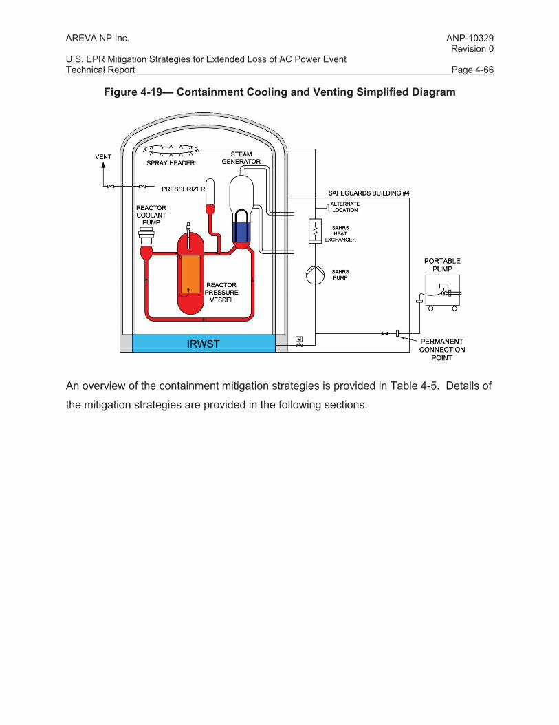
Figure 4-19— Containment Cooling and Venting Simplified Diagram ........................ 4-66
Figure 4-20—Spent Fuel Spray System Simplified Diagram ...................................... 4-77
AREVA NP Inc. ANP-10329 Revision 0 U.S. EPR Mitigation Strategies for Extended Loss of AC Power Event Technical Report Page vi
Nomenclature Acronym Definition AC Alternating Current ANPR Advance Notice of Proposed Rulemaking BDBE Beyond Design Basis Event BDBEE Beyond Design Basis External Event BPE-LGT Battery Pack Emergency Lighting BWR Boiling Water Reactor CAS Compressed Air System COM Communication System DC Direct Current EBS Extra Borating System EDG Emergency Diesel Generator EFW Emergency Feedwater ELAP Extended Loss of AC Power E-LGT Emergency Lighting EOP Emergency Operating Procedures EP Emergency Preparedness EPR Evolutionary Power Reactor EPSS Emergency Power Supply System ERDS Emergency Response Data System ESF Engineered Safety Feature ESR-LGT Escape Route-Egress Battery Pack Lighting EUPS Class 1E Uninterruptible Power Supply FB Fuel Building FLEX Diverse and Flexible Coping Strategies FSAR Final Safety Analysis Report GOTHIC Generation of Thermal-Hydraulic Information for Containments HSI Human-System Interface HVAC Heating, Ventilation, and Air Conditioning I&C Instrumentation and Control IRWST In-Containment Refueling Water Storage Tank ISG Interim Staff Guidance LOOP Loss of Offsite Power MCC Motor Control Center MCR Main Control Room MHSI Medium Head Safety Injection MS Main Steam MSRCV Main Steam Relief Control Valve MSRIV Main Steam Relief Isolation Valve MSRT Main Steam Relief Train NEI Nuclear Energy Institute
AREVA NP Inc. ANP-10329 Revision 0 U.S. EPR Mitigation Strategies for Extended Loss of AC Power Event Technical Report Page vii
Acronym Definition NPSH Net Positive Suction Head NRC U.S. Nuclear Regulatory Commission NTTF Near-Term Task Force PA Public Address PRA Probabilistic Risk Assessment PSRV Pressurizer Safety Relief Valve PWR Pressurized Water Reactor PZR Pressurizer RCP Reactor Coolant Pump RCS Reactor Coolant System RFI Request for Information RSS Remote Shutdown Station SAHRS Severe Accident Heat Removal System SAS Safety Automation System SB Safeguard Building SBLOCA Small Break Loss of Coolant Accident SBO Station Blackout (event) SBVSE Electrical Division of Safeguard Building Ventilation System SE-LGT Special Emergency Lighting SFP Spent Fuel Pool SFPS Spent Fuel Pool Spray SG Steam Generator SICS Safety Information and Control System SSC Structures, Systems, and Components SSE Safe Shutdown Earthquake SSSS Standstill Seal System UHS Ultimate Heat Sink
AREVA NP Inc. ANP-10329 Revision 0 U.S. EPR Mitigation Strategies for Extended Loss of AC Power Event Technical Report Page viii
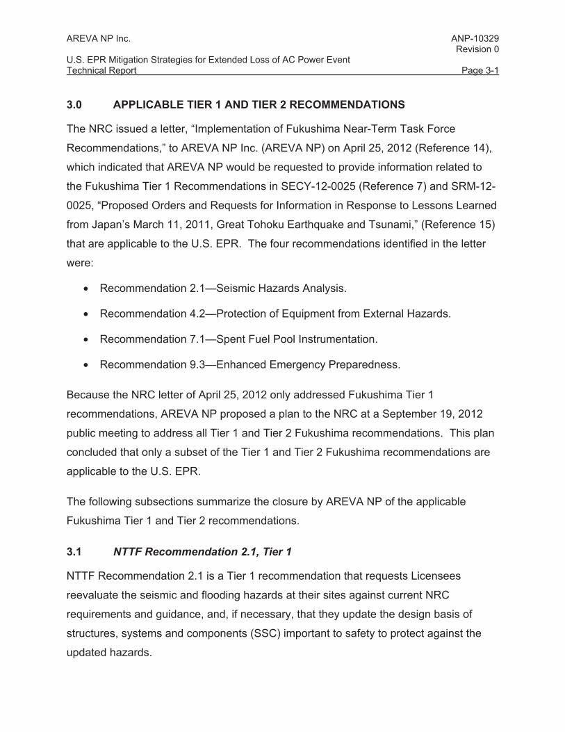
ABSTRACT
After the March 2011 accident at the Fukushima Daiichi Nuclear Power Plant in Japan,
the U.S. Nuclear Regulatory Commission (NRC) took specific regulatory actions in
areas of nuclear power plant design and emergency planning to improve the availability
and reliability of plant safety systems to mitigate a beyond design basis event from
external hazards. The NRC issued Order EA-12-049, “Order Modifying Licenses with
Regard to Requirements for Mitigation Strategies for Beyond-Design-Basis External
Events,” (Reference 1) on March 12, 2012, which requires Licensees to develop,
implement, and maintain guidance and strategies to sustain or restore core cooling,
containment integrity, and spent fuel pool (SFP) cooling capabilities following a beyond
− The boil-off rate is based on the ANS 1973 decay heat standard with 20% uncertainty.
− There is no credit for inlet subcooling.
Results
For short-term core cooling in Mode 6, analyses and evaluations were performed to
determine injection flow requirements and estimated time to boil.
The injection flow requirements to replace boil off are determined using:
Q = W (ho – hi)
where,
Q = Decay heat.
W = Injection flow rate.
ho = Core exit enthalpy (this corresponds to the enthalpy of saturated steam
at 212 °F).
hi = Injection flow enthalpy corresponding to the injection flow temperature.
The calculated injection flow required to replace boil off at 17 hours after shutdown was
approximately 230 gpm.
The time to boil was estimated using:
Time to Saturation = (Cp) (Tsat - TInitial)/(Q)
where,
Cp = Specific heat, including credited metal mass and water volumes,
BTU/lbm°F.
Tsat = Saturation temperature at atmospheric pressure, 212 °F.
AREVA NP Inc. ANP-10329 Revision 0 U.S. EPR Mitigation Strategies for Extended Loss of AC Power Event Technical Report Page 4-17
TInitial = Initial temperature of the RCS.
Q = Best-estimate decay heat, in BTU/hr.
The estimated time to boil at 16.67 hours after shutdown with an initial temperature of
140° was 3.4 minutes (3 minutes 24 seconds).
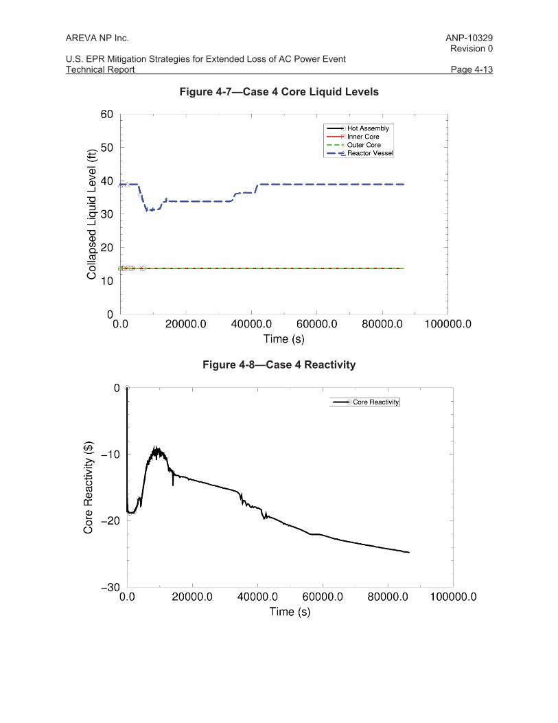
Based on these results, the following insights can be drawn:
• A coping strategy and success path exists for the ELAP event in Mode 6 using
primary side feed and bleed cooling. In particular, the core cooling acceptance
criteria given in Section 4.1.2 can be met as follows:
- The nuclear fuel in the core remains covered with coolant.
- When RCS inventory addition is initiated, borated water is used as makeup to
maintain the core subcritical.
• RCS makeup should be restored as quickly as practicable. At a minimum, a
continuous RCS injection rate of 230 gpm is needed to maintain adequate
inventory above the top of the fuel and remove core decay heat. Borated
makeup water should be used as the injection source. The boron concentration
should be equivalent to the concentration of the IRWST to ensure long-term
subcriticality.
In Mode 6, core cooling is maintained in the long term by pumped flow from the IRWST
or from a portable source with an equivalent boron concentration. The borated water
from the IRWST provides a means for the core to remain subcritical, but causes a boron
precipitation concern because of an increase in concentration from the decay heat boil
off. An analysis was performed based on the U.S. EPR FSAR Tier 2, Chapter 15 LOCA
boron precipitation methodology to determine the minimum injection flow rate needed to
preclude boron precipitation.
The minimum flow rate to reach the solubility limit was determined. Sensitivity studies
were also performed with different flow rates and a best estimate decay heat model.
AREVA NP Inc. ANP-10329 Revision 0 U.S. EPR Mitigation Strategies for Extended Loss of AC Power Event Technical Report Page 4-18
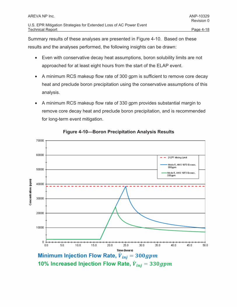
Summary results of these analyses are presented in Figure 4-10. Based on these
results and the analyses performed, the following insights can be drawn:
• Even with conservative decay heat assumptions, boron solubility limits are not
approached for at least eight hours from the start of the ELAP event.
• A minimum RCS makeup flow rate of 300 gpm is sufficient to remove core decay
heat and preclude boron precipitation using the conservative assumptions of this
analysis.
• A minimum RCS makeup flow rate of 330 gpm provides substantial margin to
remove core decay heat and preclude boron precipitation, and is recommended
for long-term event mitigation.
Figure 4-10—Boron Precipitation Analysis Results
AREVA NP Inc. ANP-10329 Revision 0 U.S. EPR Mitigation Strategies for Extended Loss of AC Power Event Technical Report Page 4-19
4.1.3.3 RCP Seal Leakage
Following a BDBEE that results in an ELAP event, the normal methods of cooling the
RCP seals with the RCP thermal barrier coolers and RCP seal injection are lost. The
ELAP transient is similar to the SBO event that has been evaluated in U.S. EPR FSAR
Tier 2, Section 8.4. In the U.S. EPR SBO mitigation strategy, the RCP SSSS is relied
upon to close to limit RCP seal leakage. A similar strategy can be applied to the ELAP
transient provided the plant parameters are maintained within the RCP SSSS
qualification envelope.
For SBO mitigation, qualification testing was performed to demonstrate that the RCP
SSSS would limit seal leakage to less than 0.5 gpm per pump for 24 hours. During the
qualification tests, the RCP SSSS was subjected to the temperature and pressure
profile representative of an SBO event.
Based on the qualification test results, an evaluation was performed to confirm that the
SBO qualification testing envelope bounded the ELAP secondary feed and bleed
cooling transient in Modes 1 through 5 during the initial 24-hour time period. For the
Case 4 results of the S-RELAP5 analysis of secondary feed and bleed cooling (refer to
Section 4.1.3.1), the evaluation concluded that the integrity and leak rate of the RCP
SSSS is bounded by the SBO qualification tests results for the first 24 hours after loss
of seal cooling.
For long-term ELAP event mitigation (i.e., beyond 24 hours), additional loss of RCP seal
cooling tests are required for the standstill seal and the lower three RCP shaft seal
stages. Test conditions will be selected based on the following considerations:
• Test conditions bound the full range of RCS conditions (temperature and
pressure) that are expected for long-term mitigation of an ELAP event initiated in
Modes 1 through 5.
• Test conditions bound the temperature range that may cause RCP seal
degradation.
AREVA NP Inc. ANP-10329 Revision 0 U.S. EPR Mitigation Strategies for Extended Loss of AC Power Event Technical Report Page 4-20
The purpose of this qualification testing is to validate the RCP shaft seal leak rate and
integrity of the shaft seals when exposed to ELAP conditions on a long term basis.
4.1.3.4 Containment Pressure Control (Integrity)
Analytical Methods
Containment pressure control was evaluated using the GOTHIC (Generation of
Thermal-Hydraulic Information for Containments) computer code. GOTHIC is a general
purpose thermal-hydraulics software package for design, licensing, safety and operating
analysis of nuclear power plant containments and other confinement buildings.
Appropriate heat transfer and fluid flow correlations are used depending on fluid state.
Special process models are used for components such as doors, valves, heat structures
and break junctions. GOTHIC solves the conservation equations for mass, momentum
and energy for multi-component, multi-phase flow. The phase balance equations are
coupled by mechanistic models for interface mass, energy and momentum transfer that
cover the entire flow regime from bubbly flow to film/drop flow, as well as single phase
flows. The interface models allow for the possibility of thermal non-equilibrium between
phases and unequal phase velocities.
GOTHIC has previously been used to analyze the containment response as discussed
in U.S. EPR FSAR Tier 2, Section 6.2. BAW-10252PA-00, “Analysis of Containment
Response to Pipe Ruptures using GOTHIC” (Reference 19), and ANP-10299P Revision
2, “Applicability of AREVA NP Containment Response Evaluation Methodology to the
U.S. EPR™ for Large Break LOCA Analysis Technical Report” (Reference 20) are
topical reports that justify application of the GOTHIC methodology to the U.S. EPR.
Because the ELAP scenario is characterized by slow, but continuous containment
pressurization, the GOTHIC containment response methodology is an appropriate
choice for this ELAP analysis.
Key Assumptions
The GOTHIC analysis of containment response was performed using the following key
assumptions and inputs:
AREVA NP Inc. ANP-10329 Revision 0 U.S. EPR Mitigation Strategies for Extended Loss of AC Power Event Technical Report Page 4-21
• The GOTHIC subdivided multi-node EPR containment model was used as the
base model.
• ELAP events were assumed to occur in either Modes 1 through 5, or Mode 6.
Mass and energy releases from RCS leakage were modeled, along with sensible
energy from the primary side and secondary side. Mass and energy releases
from RCS leakage were based on the pertinent core cooling analysis in Modes 1
through 5 (refer to Section 4.1.3.1) or in Mode 6 (refer to Section 4.1.3.2).
Results
GOTHIC analyses were performed to determine the general timing of containment
pressurization, the limiting mode for the ELAP event accident initiation relative to
containment response, and the overall feasibility of containment spray and containment
venting options to manage containment pressure response. Based on these analyses,
the following insights can be drawn:
• For an ELAP event initiated in Modes 1 through 5, the GOTHIC analysis was run
to 24 hours with no operator action. The maximum containment pressure at 24
hours was 20.1 psia. The projected time to reach the containment ultimate
design pressure was 14.76 days (refer to Section 4.1.2).
• For an ELAP event initiated in Mode 6, the GOTHIC analysis was run to 24 hours
with no operator action. During Mode 5 primary feed and bleed (which
conservatively bounds Mode 6), a maximum containment pressure of 100.7 psia
(86 psig) was reached at 24 hours, which is safely below the containment
ultimate design pressure (refer to Section 4.1.2) of 133.2 psia (118.5 psig)
• The ELAP event initiated in Mode 6 was the limiting case because of the primary
side heat rejection via primary feed and bleed cooling into the containment. The
leakage flow rate and the leakage enthalpy are significantly higher with primary
feed and bleed than with secondary heat removal.
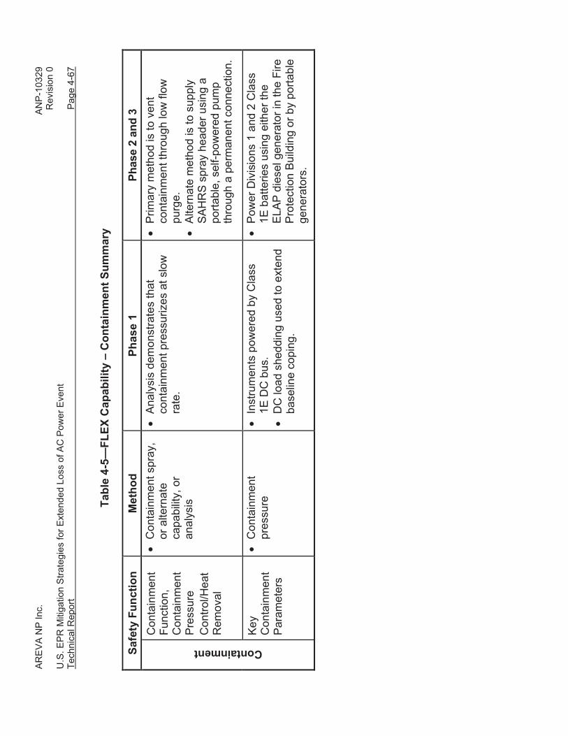
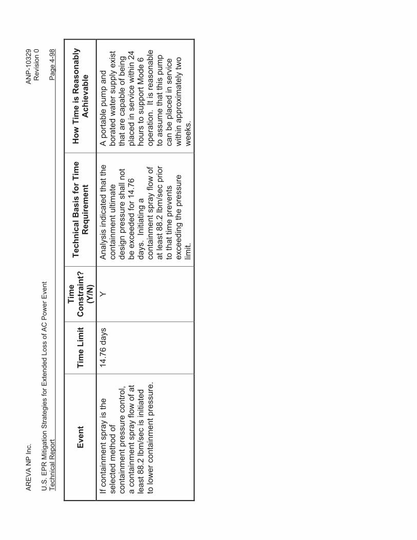
• The feasibility of using a containment spray strategy for Phase 2 and 3 event
mitigation was evaluated using the severe accident heat removal system
AREVA NP Inc. ANP-10329 Revision 0 U.S. EPR Mitigation Strategies for Extended Loss of AC Power Event Technical Report Page 4-22
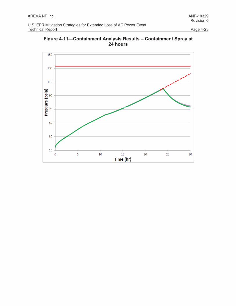
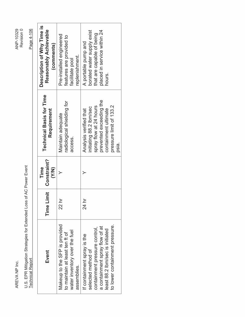
(SAHRS) spray header. A spray flow of 88.2 lbm/sec was assumed at 24 hours.
For the limiting primary feed and bleed case, containment pressure immediately
began to decrease following spray injection, as shown in Figure 4-11.
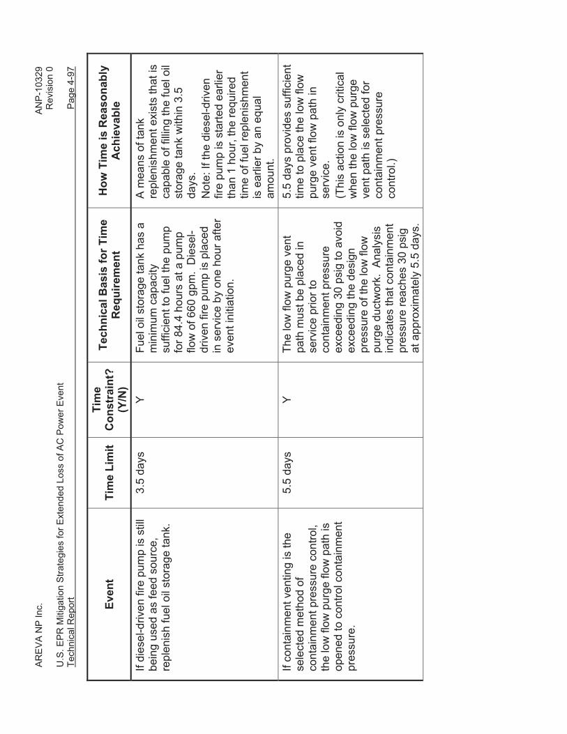
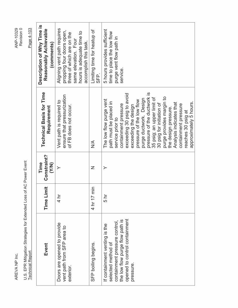
• The feasibility of using a containment venting strategy for Phases 2 and 3 event
mitigation was also evaluated. The vent path chosen was the containment low
flow purge line through a filter bank bypass line. For the limiting primary feed
and bleed case, the low flow purge vent path was opened at five hours into the
transient at a containment pressure of 39.3 psia (24.6 psig). Containment
pressure immediately began to decrease and remained below 30 psia for the
duration of the event as shown in Figure 4-12.
• The GOTHIC containment analyses demonstrated that containment
pressurization following an ELAP event is a slow transient that provides ample
time for operator action. Containment venting or containment sprays are both
viable mitigation strategies to maintain containment integrity.
AREVA NP Inc. ANP-10329 Revision 0 U.S. EPR Mitigation Strategies for Extended Loss of AC Power Event Technical Report Page 4-23
Figure 4-11—Containment Analysis Results – Containment Spray at 24 hours
AREVA NP Inc. ANP-10329 Revision 0 U.S. EPR Mitigation Strategies for Extended Loss of AC Power Event Technical Report Page 4-24
Figure 4-12—Containment Analysis Results – Containment Venting at Less than 40 psia
4.1.3.5 Safeguard Building Heatup Analysis
Analytical Methods
The GOTHIC computer code was used to evaluate heatup of the Safeguard Buildings
(SBs) following a loss of all forced ventilation resulting from an ELAP event SB 2 was
modeled by dividing the building into 12 homogeneous temperature regions (control
volumes), which were evaluated individually with heat transfer to adjoining regions
being considered. Areas with insignificant heat loads that were not expected to
challenge equipment operability limit were grouped together into a single control volume
for model simplification. Heat loads were modeled as heaters within each control
volume.
AREVA NP Inc. ANP-10329 Revision 0 U.S. EPR Mitigation Strategies for Extended Loss of AC Power Event Technical Report Page 4-25
Key Assumptions
The GOTHIC analysis of SB 2 response was performed using the following key
assumptions and inputs:
• Room temperatures begin at the maximum normal temperature and 60%
humidity.
• Air flow between rooms is not modeled, with the exception of flow between
switchgear room 2UJK18029 and another control volume consisting of the other
switchgear room and the hall. The door to switchgear room (2UJK18029)
contains a two-foot-by-four-foot grating in it to allow airflow.
• Radiation heat transfer is neglected.
• Ambient temperature is 100 °F, consistent with Section 4.1.4.
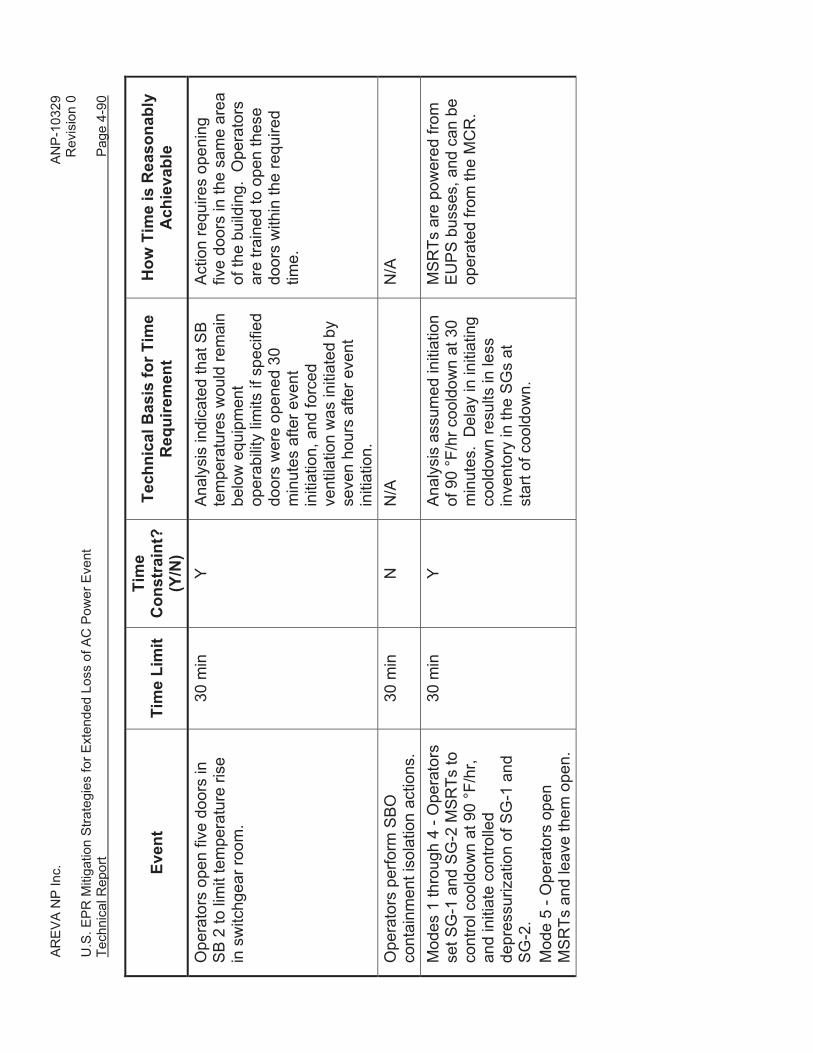
• Five specified doors on the + 26’-7” elevation of the SB 2 are opened at 30
minutes after event initiation.
• Forced ventilation to SB 2 is restored at seven hours after event initiation.
Results
The results of the analysis indicated that all areas of SB 2 were maintained less than
130 °F. The most limiting room was the I&C cabinet room (2UJK18005), which reached
a temperature of 121 °F. After initiation of forced flow at seven hours, the temperatures
in all areas of SB 2 were maintained less than approximately 115°F.
4.1.3.6 Main Control Room Heatup Analysis
Analytical Methods
The GOTHIC computer code was used to conduct a parametric study of heatup of the
MCR following a loss of forced ventilation. Refer to Section 4.1.3.4 for a description of
the GOTHIC code. The MCR was modeled as a single node, with a single heat
structure, comprised of concrete with a painted surface. The concrete surfaces of the
room, as well as the free volume of air, served as heat sinks. The heat load was
AREVA NP Inc. ANP-10329 Revision 0 U.S. EPR Mitigation Strategies for Extended Loss of AC Power Event Technical Report Page 4-26
modeled as a heater. The parametric study examined changes in free volume, heat
source, and concrete surface area.
Key Assumptions
The GOTHIC analysis of MCR response was performed using the following key
assumptions and inputs:
• The MCR and the shift room were assumed to constitute a single, homogeneous,
free volume with concrete walls, ceiling and floor.
• The MCR was assumed to have a drop ceiling which reduced the available free
volume and concrete surface area. Additionally, the free volume of the MCR was
further reduced for conservatism.
• The thickness of the concrete walls, floor, and ceiling was conservatively
assumed to be half the thickness. The wall was conservatively treated as an
insulated boundary, which thermally isolated the MCR from the surrounding
rooms.
• The surface area of the walls, floor, and ceiling was reduced for conservatism.
• The concrete surface was assumed to be painted, with the thickness and
properties of the coating typical for painted surfaces.
• The initial room temperature was conservatively assumed to be 80 °F.
Results
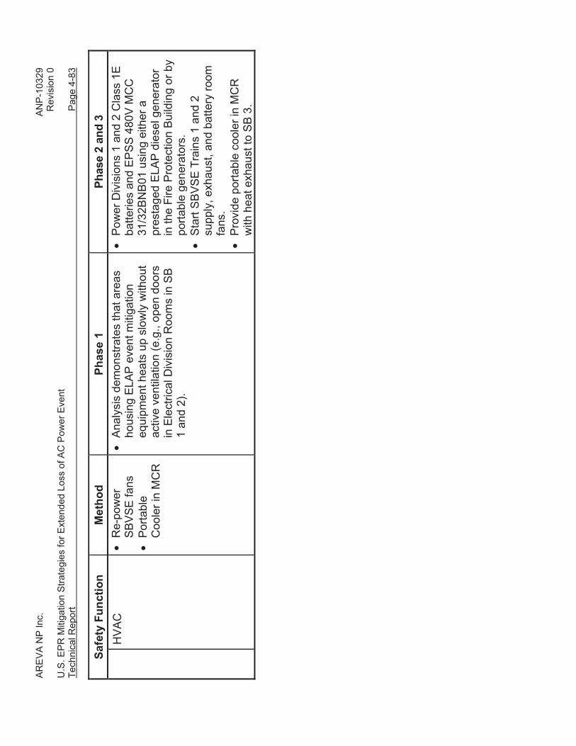
The parametric study demonstrated that if ventilation or cooling is not restored to the
MCR for at least seven hours following an ELAP event, then:
• The MCR temperature would not exceed 110 °F for at least seven hours during
an ELAP event with a heat load not more than 10 BTU/sec and an initial
temperature not more than 80 °F.
• The MCR temperature would not exceed 95.1 °F if the heat load is not more than
5 BTU/sec.
AREVA NP Inc. ANP-10329 Revision 0 U.S. EPR Mitigation Strategies for Extended Loss of AC Power Event Technical Report Page 4-27
4.1.3.7 Main Control Room Portable Cooler Sizing Evaluation
Analytical Methods
An evaluation was performed to determine the total heat input to the U.S. EPR MCR
following an ELAP event to determine the minimum performance requirements for a
portable cooler (air conditioner) for the MCR. The evaluation considered the heat loads
from personnel and MCR equipment energized during an ELAP event to determine the
total MCR heat load. This total MCR heat load was then compared against the
GOTHIC parametric study results described in Section 4.1.3.6 to confirm that heatup of
the MCR was acceptable. Additionally, this total MCR heat load was used to size a
portable cooler for the MCR.
Key Assumptions • Five operators were assumed in the MCR with heat input from each operator
assumed to be 475 BTU/hr.
• Heat input to the MCR from emergency lighting is 1.5 kW.
• Heat input from the Safety Information And Control System (SICS) cabinets in
the MCR is assumed to 2.4 kW.
Results
The evaluation determined that the MCR heat input rate was 4.36 BTU/sec, or about
16,000 BTU/hr. Examination of the results of the MCR heatup parametric study
described in Section 4.1.3.6 indicated that with a heat load of 5.0 BTU/sec, the MCR
temperature will rise at most to 95.1 °F within seven hours. Based on these results, the
minimum portable cooler sizing was conservatively set at 32,000 BTU/hr (i.e., twice the
expected heat load) to provide the capability to cool down the MCR. The portable MCR
cooler would need to be placed in service within seven hours of the ELAP initiating
event.
AREVA NP Inc. ANP-10329 Revision 0 U.S. EPR Mitigation Strategies for Extended Loss of AC Power Event Technical Report Page 4-28
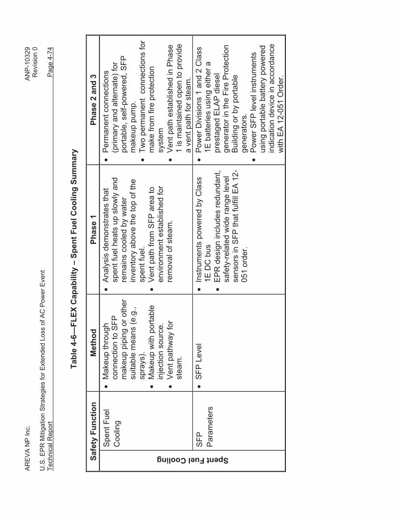
4.1.3.8 Spent Fuel Pool Time to Boil and Makeup Analysis
Key Assumptions
The SFP time to boil and makeup analysis was performed using the following key
assumptions and inputs:
• During an ELAP event, spent fuel cooling by the spent fuel pool cooling system
(SFPCS) heat exchangers is lost. Heatup of the SFP and boiling can be credited
to cool the spent fuel, provided the water level is maintained above the top of the
spent fuel (refer to Section 4.1.2). This spent fuel cooling strategy is consistent
with NRC Staff guidance given in Question 5.8.4 in NUREG-1628, “Staff
Responses to Frequently Asked Questions Concerning Decommissioning of
Nuclear Power Reactors” (Reference 25).
• A conservative number of rack spaces is assumed with all rack spaces filled (22
years of fuel storage).
• The maximum SFP heat load was assumed at 130 hours after reactor trip based
on a full core off-load. This SFP heat load conservatively assumes at least 15%
excess margin.
• Heat losses from the SFP are conservatively neglected.
Results
The SFP time to boil and makeup analysis was performed to determine the bulk SFP
heatup time and boil-off rate.
The SFP bulk heat-up time is conservatively calculated using Δt =MCpΔT/Q,
where,
M (lbm) is the mass of water in the SFP.
Cp (BTU/lbm°F) is the specific heat.
ΔT (°F) is the temperature rise.
AREVA NP Inc. ANP-10329 Revision 0 U.S. EPR Mitigation Strategies for Extended Loss of AC Power Event Technical Report Page 4-29
Δt (hrs) is the time to complete the temperature rise.
Q (BTU/hr) is the heat added to the SFP from the spent fuel stored in the
pool.
The boil-off rate is calculated using:
Boil off Rate = Q / hfg,
where,
Q (BTU/hr) is the heat added to the SFP from the spent fuel stored in the pool.
hfg (BTU/lbm) is the latent heat of evaporation.
Based on these analyses, the following insights can be drawn:
• During a full core offload refueling condition, the time to reach SFP bulk boiling
following the loss of all SFP cooling is approximately 4.3 hours. The initial boil-
off rate is 140 gpm. The boil-off rate decreases over time as the spent fuel decay
heat decreases.
• If spent fuel cooling is not restored, then an additional 30.5 hours is available to
boil-off the pool inventory, while maintaining the level above the top of the spent
fuel racks (refer to Section 4.1.2). Therefore, the total time to uncover the spent
fuel (from a temperature of 140 °F) is approximately 4.3 + 30.5 hours = 34.8
hours.
• Since the operators have approximately 35 hours to restore cooling and/or
makeup to the SFP, boiling of the SFP can be credited as the Phase 1 event
mitigation method, and cooling and/or makeup to the SFP can be credited for
Phases 2 and 3 event mitigation.
AREVA NP Inc. ANP-10329 Revision 0 U.S. EPR Mitigation Strategies for Extended Loss of AC Power Event Technical Report Page 4-30
4.1.3.9 DC Load Shedding
Analytical Methods
To determine how long the Class 1E uninterruptible power supply (EUPS) system
battery capacity can be extended, the following process was used:
• The loads on the EUPS battery were identified based on the design basis
accident EUPS battery sizing calculation and the Electrical Load List.
• Loads required for ELAP Phase 1 scenario mitigation were identified and their
operation defined.
• Loads to be shed from the EUPS battery for an ELAP event were identified.
• The time elapsed before ELAP load shedding takes place was identified.
• The ELAP EUPS duty cycle was defined by applying by the ELAP Phase 1
equipment operation and load shedding sequence to the loads supplied by the
EUPS battery.
• The margins to apply for the EUPS batteries during an ELAP event were
determined.
• The duration of battery discharge availability until the minimum acceptable cell
voltage is reached was determined using the EUPS battery cell type, the ELAP
EUPS duty cycle, and the ELAP margins.
Key Assumptions
The DC load shedding analysis was performed using the following key assumptions and
inputs:
• No additional accidents or failures are assumed to occur immediately prior to or
during the event, other than those causing the ELAP event.
• Reasonably protected installed electrical distribution equipment, including
inverters and cabling, is assumed to remain available.
AREVA NP Inc. ANP-10329 Revision 0 U.S. EPR Mitigation Strategies for Extended Loss of AC Power Event Technical Report Page 4-31
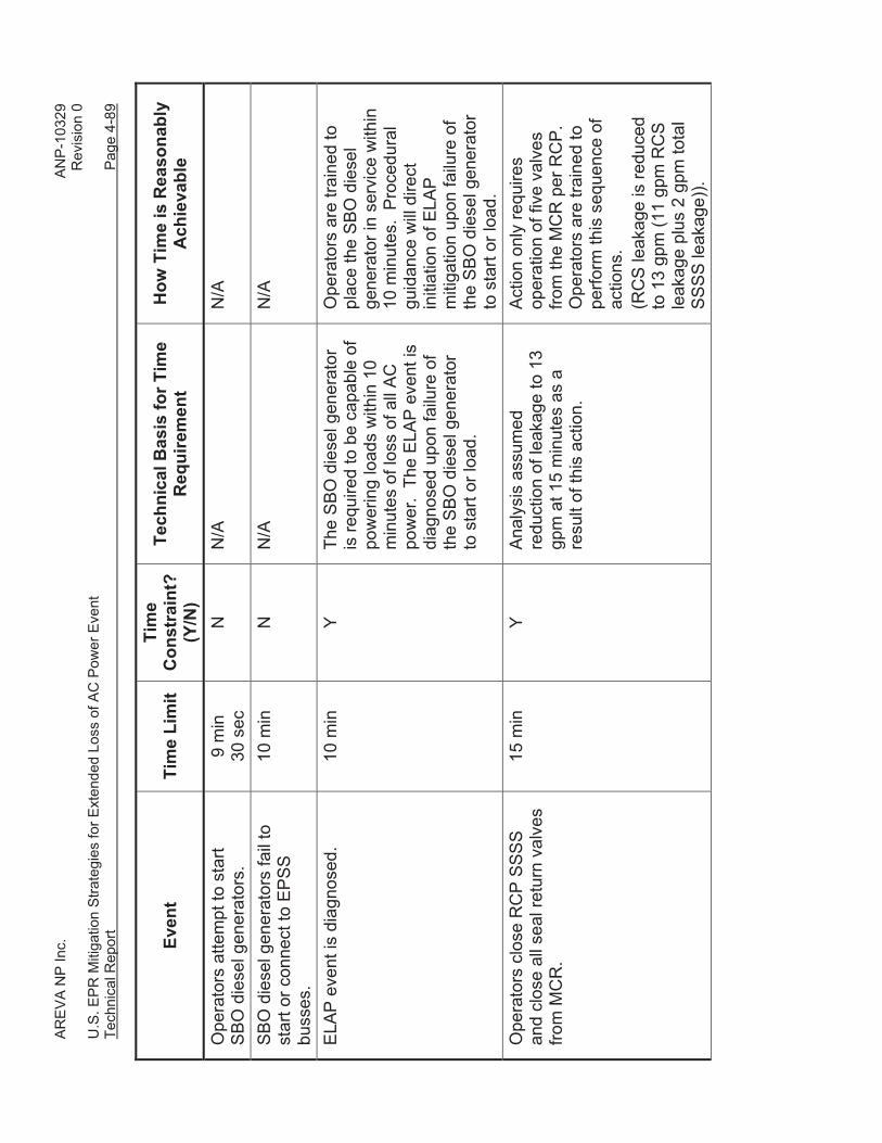
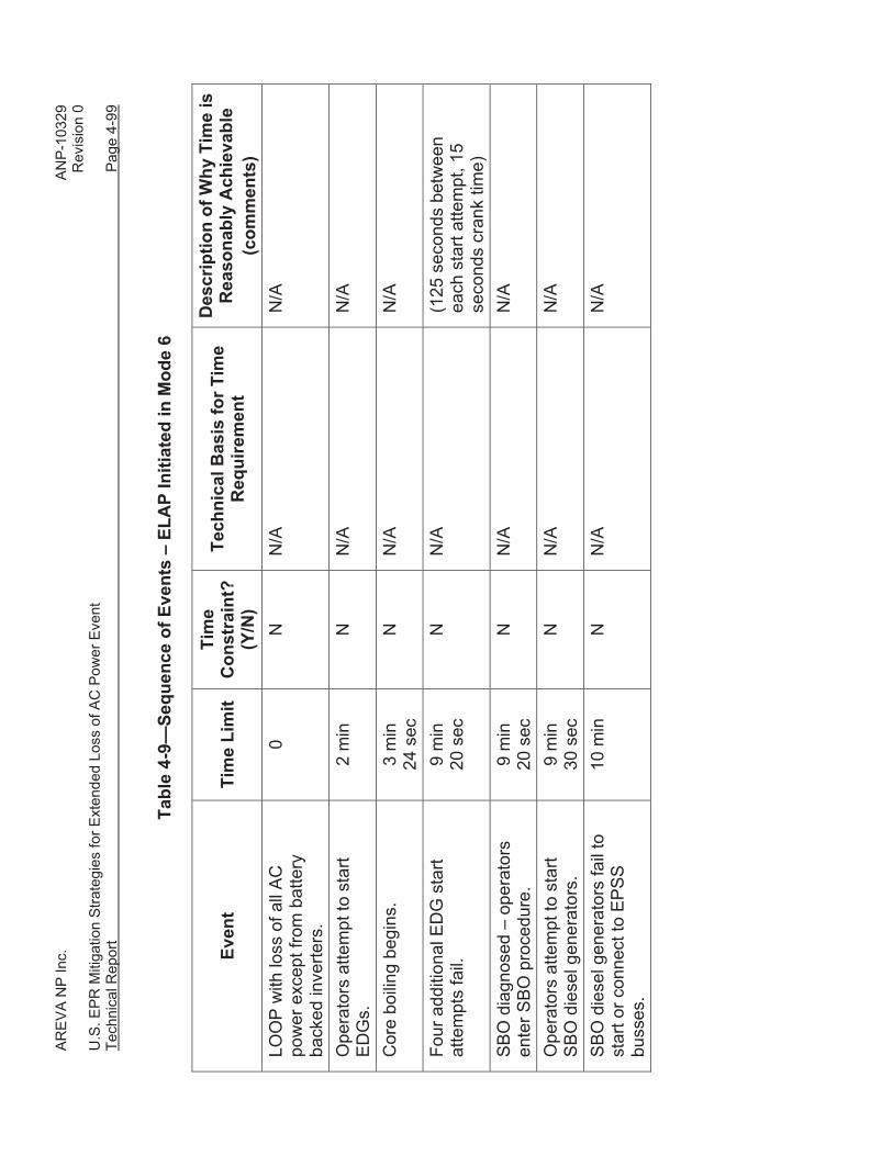
• ELAP event is identified at 10 minutes after initiation of the event after offsite
power is lost, all EDGs fail to start or load, and all SBO diesel generators fail to
start or load.
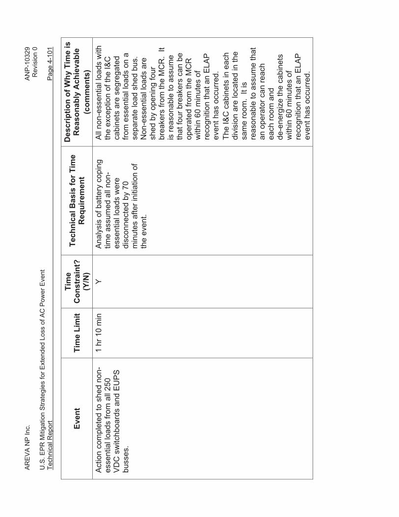
• DC load shedding is assumed to take 60 minutes to complete and is completed
by 70 minutes after ELAP event initiation.
• Only those containment isolation valves identified in the U.S. EPR SBO coping
strategy (refer to Section 8.4 of the U.S. EPR FSAR) and the primary coolant
injection pump containment isolation valve (30JND11AA012) are assumed to be
operated for the ELAP event.
• A minimum acceptable battery output of 210 Vdc is assumed.
• A 5% design margin is included in the cell size to account for less than optimum
operating conditions of the battery. An aging factor of 1.25 is applied to the cell
capacity to provide reasonable assurance that the battery is capable of meeting
its design loads throughout its service life. A temperature correction factor of
1.11 (60 °F) is applied to the cell capacity.
Results
Based on this analysis, it was determined that the EUPS battery discharge duration can
be extended from two hours to eight hours and 30 minutes. The overall timeline for DC
load shedding is provided in Figure 4-13. To extend the EUPS battery capacity to this
duration, the following operator actions are required:
• Identify the ELAP event and begin DC load shedding in all four divisions of the
EUPS within 10 minutes after initiation of the ELAP event.
• Complete shedding of non-ELAP loads in all four divisions of the EUPS within 70
minutes after initiation of the ELAP event.
AREVA NP Inc. ANP-10329 Revision 0 U.S. EPR Mitigation Strategies for Extended Loss of AC Power Event Technical Report Page 4-32
• Before the EUPS divisions are depleted at eight hours and 30 minutes, re-
energize credited EUPS Divisions 1 and 2 for long-term event mitigation in
Phases 2 and 3.
Figure 4-13—ELAP Battery Discharge Duration
4.1.4 Reasonable Protection of Installed and Portable Equipment
The term “reasonable protection,” within the context of this technical report, means that
the design of the SSC it is describing either meets the U.S. EPR design basis for the
applicable external hazards, or has been shown by analysis or test to meet or exceed
the U.S. EPR design basis. This definition is consistent with the definition of “robust” in
NEI 12-06 (Reference 3).
Additionally, NEI 12-06 (Reference 3) provides the following guidance:
Section 3.2 Performance Attributes states:
“…installed equipment that is designed to be robust with respect to DBEE
is assumed to be fully available”.
AREVA NP Inc. ANP-10329 Revision 0 U.S. EPR Mitigation Strategies for Extended Loss of AC Power Event Technical Report Page 4-33
Section 3.2.1.3 Initial Conditions, (6) states:
“Permanent plant equipment that is contained in structures with designs
that are robust with respect to seismic events, floods and high winds and
associated missiles are available.”
Section 3.2.1.3 (8) states:
“Installed electrical distribution systems…remain available provided they
are protected…”
The non-safety-related SSC (for example, diesel-driven fire water pump, discharge
piping, portable equipment, Fire Protection Building, and the fire water storage tanks)
that are relied upon to mitigate an ELAP event are designed to meet the FLEX
reasonable protection standards. The following subsections comprise a list of external
hazards defined in Section 2 of NEI 12-06 (Reference 3) and a description of the way in
which the non-safety-related SSC, including the FLEX equipment, portable equipment,
and Fire Protection Building, meet the FLEX reasonable protection requirements.
NEI 12-06 (Reference 3) provides the following guidance:
Section 2.3 states:
“Considering the external hazards applicable to the site, the FLEX
mitigation equipment should be stored in a location or locations such that
it is reasonably protected such that no one external event can reasonably
fail the site FLEX capability. Reasonable protection can be provided for
example, through provision of multiple sets of portable on-site equipment
stored in diverse locations or through storage in structures designed to
reasonably protect from applicable external events.”
AREVA NP Inc. ANP-10329 Revision 0 U.S. EPR Mitigation Strategies for Extended Loss of AC Power Event Technical Report Page 4-34
Seismic
The Fire Protection Building and the fire water storage tanks are the only non-safety-
related structures that are credited for Phase 1 event mitigation of an ELAP event. The
Fire Protection Building and the fire water storage tanks are designed to meet or exceed
ASCE 7-10, “Minimum Design Loads for Buildings and Other Structures” (Reference
22), consistent with the FLEX guidance.
Equipment that is credited for Fukushima event mitigation is either Seismic Category I,
or is non-safety-related equipment that is installed in Seismic Category I, Seismic
Category II and Conventional Seismic structures with the following clarification:
To provide adequate functionality following a safe shutdown earthquake (SSE), the
following supplemental seismic requirements are imposed:
• For valves and piping – ANSI/ASME B31.1 (Reference 24). For example, this
includes the non-safety-related piping and valves from the diesel-driven fire water
pumps to the Emergency Feedwater system.
• For other SSC – ASCE 43-05, “Seismic Design Criteria for Structures, Systems,
and Components in Nuclear Facilities” (Reference 23). For example, this
includes the ELAP diesel generator.
This seismic qualification strategy for equipment is consistent with the seismic
qualification strategy used for the non-safety-related Fire Protection System as
described in U.S. EPR FSAR Tier 2, Section 9.5.1.
Flooding
The U.S. EPR is designed as a “dry site” location, which means the plant grade level is
located one foot above the flood elevation. This refers to the Seismic Category I safety-
related structures. The Fire Protection Building and the fire water storage tanks are the
only non-safety-related structures that are credited for Phase 1 event mitigation of an
ELAP event. Taking this into account, the Fire Protection Building and the fire water
storage tanks are designed and constructed at least one foot above the flood elevation.
AREVA NP Inc. ANP-10329 Revision 0 U.S. EPR Mitigation Strategies for Extended Loss of AC Power Event Technical Report Page 4-35
Severe Storms with High Winds / Missile Protection
The Fire Protection Building and fire water storage tanks are designed to meet or
exceed ASCE 7-10 (Reference 22). In accordance with NEI 12-06 FLEX requirements,
the Fire Protection Building and the fire water storage tanks are missile protected.
Missile protection of the Fire Protection Building and fire water storage tanks is provided
for a hurricane wind speed of 230 mph per Regulatory Guide 1.221 (Reference 19).
Selection of this hurricane wind speed is consistent with U.S. EPR FSAR Tier 2, Section
3.3.2.1.
Snow, Ice, and Extreme Cold
The Fire Protection Building and fire water storage tanks are designed to meet or
exceed ASCE 7-10 (Reference 22), consistent with the FLEX guidance. Minimum
temperatures for design of non-safety systems in the U.S. EPR are based on a best-
estimate, 1% exceedance value of -10 °F. Because of the beyond design basis nature
of the ELAP event, design evaluations of equipment performance (safety-related or non-
safety-related) are similarly based on a best-estimate, 1% exceedance value of -10 °F.
High Temperatures
In accordance with NEI 12-06 (Reference 11), equipment should be maintained at a
temperature within a range to support its likely function when called upon. Maximum
temperatures for design of non-safety systems are based on a best-estimate, 1%
exceedance value of 100 °F dry bulb / 77 °F wet bulb coincident. Because of the
beyond design basis nature of the ELAP event, design evaluations of equipment
performance (safety-related or non-safety-related) are similarly based on a
best-estimate, 1% exceedance value of 100 °F dry bulb / 77 °F wet bulb coincident.
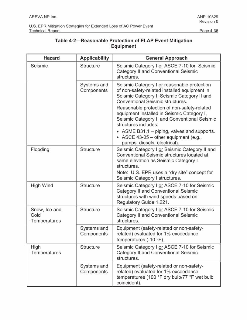
Table 4-2 provides a summary of reasonable protection.
AREVA NP Inc. ANP-10329 Revision 0 U.S. EPR Mitigation Strategies for Extended Loss of AC Power Event Technical Report Page 4-36
Table 4-2—Reasonable Protection of ELAP Event Mitigation Equipment
Hazard Applicability General Approach Seismic Structure Seismic Category I or ASCE 7-10 for Seismic
Category II and Conventional Seismic structures.
Systems and Components
Seismic Category I or reasonable protection of non-safety-related installed equipment in Seismic Category I, Seismic Category II and Conventional Seismic structures. Reasonable protection of non-safety-related equipment installed in Seismic Category I, Seismic Category II and Conventional Seismic structures includes: • ASME B31.1 – piping, valves and supports. • ASCE 43-05 – other equipment (e.g.,
pumps, diesels, electrical). Flooding Structure Seismic Category I or Seismic Category II and
Conventional Seismic structures located at same elevation as Seismic Category I structures. Note: U.S. EPR uses a “dry site” concept for Seismic Category I structures.
High Wind Structure Seismic Category I or ASCE 7-10 for Seismic Category II and Conventional Seismic structures with wind speeds based on Regulatory Guide 1.221.
Snow, Ice and Cold Temperatures
Structure Seismic Category I or ASCE 7-10 for Seismic Category II and Conventional Seismic structures.
Systems and Components
Equipment (safety-related or non-safety-related) evaluated for 1% exceedance temperatures (-10 °F).
High Temperatures
Structure Seismic Category I or ASCE 7-10 for Seismic Category II and Conventional Seismic structures.
Systems and Components
Equipment (safety-related or non-safety-related) evaluated for 1% exceedance temperatures (100 °F dry bulb/77 °F wet bulb coincident).
AREVA NP Inc. ANP-10329 Revision 0 U.S. EPR Mitigation Strategies for Extended Loss of AC Power Event Technical Report Page 4-37
4.1.5 Mitigation Strategies
Based on the analytical bases provided in Section 4.1.3 and the reasonable protection
requirements provided in Section 4.1.4, mitigation strategies were developed to satisfy
the overall acceptance criteria given in Section 4.1.2. In particular, mitigation strategies
were grouped as follows:
• AC and DC Power (Section 4.1.5.1).
• Core Cooling in Modes 1 through 5 (Secondary Side Feed and Bleed) (Section
4.1.5.2).
• Core Cooling in Mode 6 with the Reactor Vessel Head Removed (Section
4.1.5.3).
• Containment Pressure Control (Integrity) (Section 4.1.5.4).
• Spent Fuel Cooling (Section 4.1.5.5).
• Instrumentation and Controls (Section 4.1.5.6).
• Support Functions (Section 4.1.5.7).
Details of the mitigation strategy for each of these groupings are provided in the
following subsections.
4.1.5.1 AC and DC Power
During an ELAP event, DC power is required for operation of electrical switchgear and
I&C systems and for operation of essential AC motor-operated valves that are battery
backed. The only power sources available during Phase 1 event mitigation are the
two-hour batteries and their associated EUPS busses. Actions are required to extend
the period of time that this power is available.
In the U.S. EPR EUPS design, each of the 250 VDC two-hour batteries
(31/32/33/34BTD01) is connected to a 250 VDC switchboard (31/32/33/34BUC). One
of two redundant battery chargers (31/32/33/34BTP01 or 31/32/33/34BTP02) is
AREVA NP Inc. ANP-10329 Revision 0 U.S. EPR Mitigation Strategies for Extended Loss of AC Power Event Technical Report Page 4-38
connected to each 250 VDC switchboard. The EUPS battery chargers BTP01 and
BTP02 are normally supplied 480 VAC input power by the emergency power supply
system (EPSS). Battery charger BTP01 is supplied by EPSS load center BMC in
Divisions 1 and 4 and by EPSS motor control center (MCC) BNA02 in Divisions 2 and 3.
Battery charger BTP02 is supplied by EPSS load center BMB in all four divisions. The
battery chargers rectify the 480 VAC power to 250 VDC power and furnish electrical
energy for the steady-state operation of loads connected to 250 VDC switchboards,
while returning its battery to a full state of charge or maintaining its battery in a fully
charged state.
Each 250 VDC switchboard provides input power to an inverter. The inverter is used to
transform the DC power to three phase AC power to the EUPS busses.
For the mitigation of an ELAP event, all non-essential loads with the exception of the
I&C cabinets are segregated from essential loads on separate AC and DC busses,
referred to as “load shed busses.” Refer to U.S. EPR FSAR Tier 2, Figure 8.3-5. Each
load shed bus is connected to the associated EUPS bus or 250 VDC switchboard by an
isolation device that can be remotely operated from the Main Control Room (MCR). An
ELAP condition is identified shortly after it has been determined that the EPSS buses
cannot be energized from the EDGs or the SBO diesel generators. All load shed bus
infeed isolation devices are opened from the MCR within 60 minutes after determination
that an ELAP is in progress to conserve the stored energy in the batteries. Nine SAS
cabinets in Divisions 1 and 4, six safety automation system (SAS) cabinets in Divisions
2 and 3, and one SICS remote shutdown station (RSS) workstation cabinet in Divisions
1 and 4 are de-energized locally by opening isolation devices at the cabinets. These
actions extend battery availability to eight hours and 30 minutes as discussed in Section
4.1.3.9.
Prior to depletion of the batteries, the batteries in Divisions 1 and 2 are recharged from
a prestaged, permanently installed dedicated diesel generator using the Divisions 1 and
2 battery chargers. The diesel generator is located in the Fire Protection Building and is
AREVA NP Inc. ANP-10329 Revision 0 U.S. EPR Mitigation Strategies for Extended Loss of AC Power Event Technical Report Page 4-39
referred to as the ELAP diesel generator. The ELAP diesel generator is independent
from the plant and is also used to power permanently-installed plant equipment that is
credited for Phase 2 and 3 event mitigation (for example, the primary coolant injection
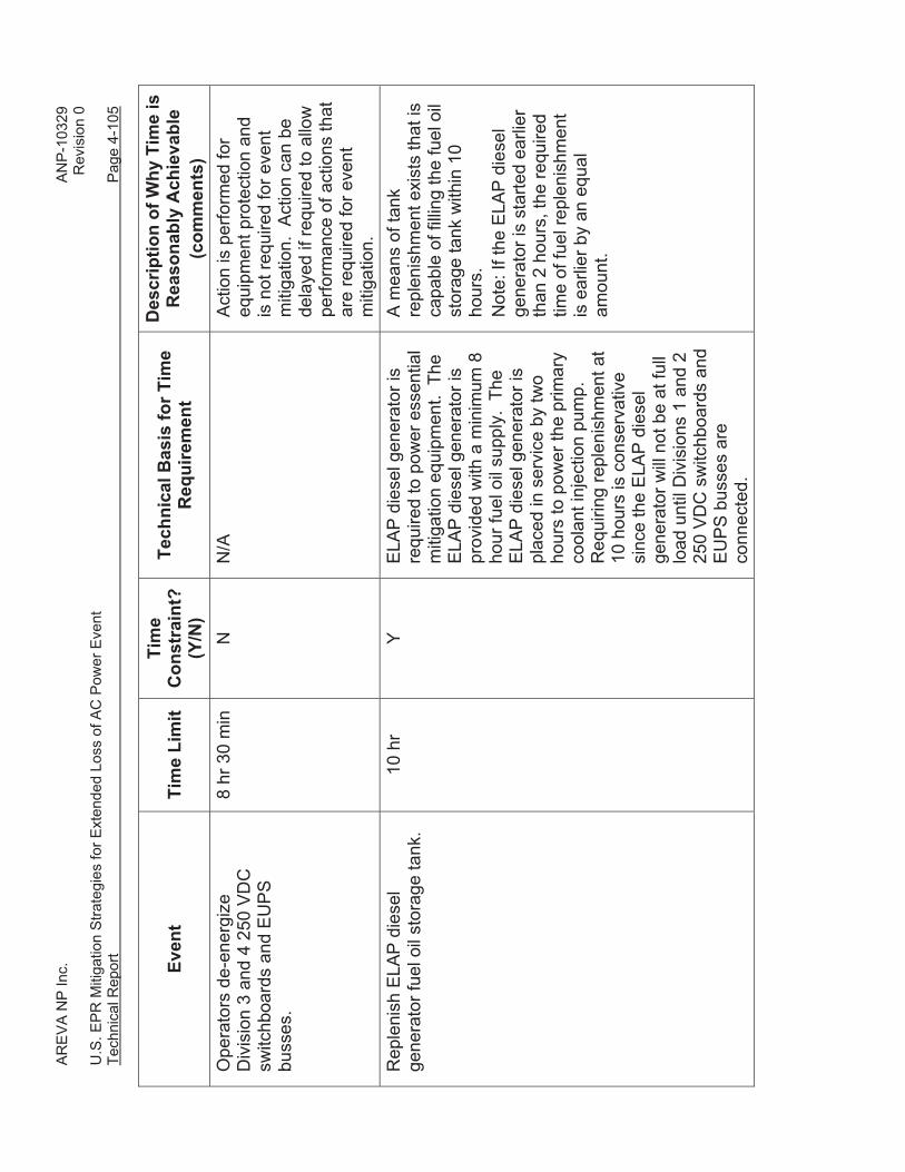
pump). This ELAP diesel generator is provided with a diesel fuel storage tank with a
minimum capacity corresponding to eight hours of fully loaded operation. The ELAP
diesel fuel storage tank is provided with external fill connections to allow replenishment
in Phases 2 and 3. The ELAP diesel generator has a minimum load capability of 650
kw.
The ELAP diesel generator is a 480 VAC generator with a transformer to step up the
voltage to 6.9 kV. The power is transmitted from the Fire Protection Building to the SB
at 6.9 kV, and stepped down to 480V using a 6.9 kV to 480V step-down transformer.
The 6.9 kV to 480V step-down transformer is located in SB 2 to meet FLEX reasonable
protection requirements.
The feed from the ELAP diesel generator is routed to two transfer switches. Refer to
Figure 4-14. One switch is located in the Division 1 feed from 6.9 kV switchgear 31BDB
to EPSS 480V load center 31BMB, and the other is located in the Division 2 feed from
6.9 kV switchgear 32BDB to EPSS 480V load center 32BMB. The transfer switches are
located in SBs 1 and 2, which meet the FLEX reasonable protection requirements.
Two additional transfer switches are provided that allow connection of 480V portable
generators, which are provided by the COL applicant. One of the transfer switches is
capable of providing power from either the ELAP diesel generator or a portable
generator to the transfer switches feeding both 31BMB and 32BMB. The other transfer
switch is only capable of providing power from either the ELAP DG or a portable
generator to the transfer switch feeding 32BMB. Temporary connections to each of
these transfer switches is provided from easily accessible electrical connections located
at grade level inside the SBs. The transfer switches are arranged to allow the portable
diesel generator at each connection to feed one EPSS 480V load center, or a larger
portable generator connected to the transfer switch capable of providing power to both
AREVA NP Inc. ANP-10329 Revision 0 U.S. EPR Mitigation Strategies for Extended Loss of AC Power Event Technical Report Page 4-40
31BMB and 32BMB to feed both EPSS 480V load centers. This provides the COL
applicant the option of providing one larger, or two smaller portable diesel generators.
This AC and DC repowering mitigation strategy reflects the following considerations:
• At least two 250 VDC switchboards (Divisions 1 and 2) and their associated
EUPS busses must be powered from the ELAP diesel generator because all
systems are not four-division or four-train redundant, and certain equipment
requires power from a minimum of two EUPS divisions to be operable. The main
steam relief isolation valves (MSRIVs) require two EUPS divisions to be
operable. The communications equipment and special emergency lighting is not
four-division or four-train redundant either.
• The Division 3 and Division 4 250 VDC switchboards and their associated EUPS
busses are de-energized by eight hours and 30 minutes after initiation of the
event prior to depletion of their associated batteries. All loads are stripped from
the Division 3 and Division 4 250 VDC switchboards and EUPS busses, and then
the associated battery isolation device is opened. These actions are performed
for equipment protection of the batteries, and are not required for event
mitigation.
• The plant operators have ample time (eight hours and 30 minutes after initiation
of the event) to repower the EUPS Divisions 1 and 2. As a result, the ELAP
event can be mitigated in the short term (Phase 1) and long term (Phases 2 and
3) using only Division 1 and 2 equipment without power interruption.
The sequence of actions and required completion times for re-energizing Divisions 1
and 2 differ depending upon the plant mode at event initiation.
Modes 1 through 5
If the ELAP event is initiated in Modes 1 through 5, action is required to place the ELAP
diesel generator in service within seven hours after event initiation to allow operation of
Division 1 and Division 2 supply and exhaust ventilation fans of the electrical division of
AREVA NP Inc. ANP-10329 Revision 0 U.S. EPR Mitigation Strategies for Extended Loss of AC Power Event Technical Report Page 4-41
the safeguard building ventilation system (SBVSE). All loads are stripped from EPSS
480V load centers 31BMB and 32BMB and the four transfer switches are aligned to
supply power from the ELAP diesel generator to the 480V load centers. The ELAP
diesel generator is then started and its output breaker is closed, energizing 31BMB and
32BMB. All loads are stripped from 480V MCC 31BNB01 and 32BNB01, and the MCCs
are energized by closing the feeder breakers from EPSS 480V load center 31BMB and
32BMB. The load breakers on 31BNB01 and 32BNB01 for the SBVSE Trains 1 and 2
supply, exhaust, and battery room fans are then closed.
The breakers on EPSS 480V load center 31BMB for battery charger 31BTP02 and on
480V load center 32BMB for battery charger 32BTP02 are closed prior to depletion of
the Division 1 and Division 2 batteries at eight hours and 30 minutes after event
initiation.
Mode 6 with the Reactor Vessel Head Removed
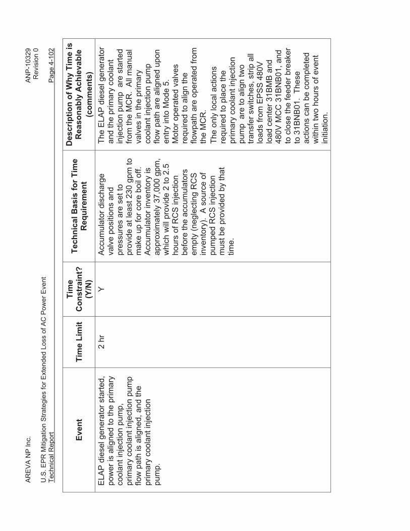
If the ELAP event is initiated in Mode 6 with the reactor vessel head removed,
repowering of Divisions 1 and 2 is performed in three phases to minimize the time
required to place the primary coolant injection pump in service.
In the first phase, the primary coolant injection pump is required to be placed in service
within two hours after event initiation, prior to exhaustion of the accumulator inventory
(refer to Section 4.1.3.2). For this phase, only 31BMB and 31BNB01 are re-energized
to provide power to the pump. In the second phase, 32BMB and 32BNB01 are
energized to allow operation of Division 2 SBVSE supply and exhaust ventilation fans.
In the third phase the Divisions 1 and 2 EUPS 250 VDC switchboards and busses are
powered from the ELAP diesel generator.
To implement the first phase, two transfer switches are positioned to align the output of
the ELAP diesel generator to EPSS 480V load center 31BMB. All loads are stripped
from EPSS 480V load center 31BMB and 480V MCC 31BNB01. The ELAP diesel
generator is started and its output breaker is closed, restoring electrical power to EPSS
AREVA NP Inc. ANP-10329 Revision 0 U.S. EPR Mitigation Strategies for Extended Loss of AC Power Event Technical Report Page 4-42
480V load center 31BMB. EPSS 480V MCC 31BNB01 is energized by closing its
feeder breaker from EPSS 480V load center 31BMB.
In the second phase, action is required to power EPSS 480V MCC 32BNB01 to allow
operation of Division 2 SBVSE supply and exhaust ventilation fans within seven hours
after event initiation. All loads are stripped from EPSS 480V load center 32BMB and
480V MCC 32BNB01. Two transfer switches are positioned to align the output of the
ELAP diesel generator to EPSS 480V load center 32BMB. EPSS 480V MCC 32BNB01
is energized by closing the feeder breaker on EPSS 480V load center 32BMB. EPSS
480V MCC 31BNB01, which supplies the SBVSE Train 1 fans, was energized in the first
phase. The load breakers on 31BNB01 and 32BNB01 for the SBVSE Trains 1 and 2
supply, exhaust, and battery room fans are then closed.
In the third phase, action is required to power the Division 1 and Division 2 250 VDC
switchboards and EUPS busses from the ELAP diesel generator prior to depletion of the
Division 1 and Division 2 batteries. To accomplish this, the breakers on EPSS 480V
load center 31BMB for battery charger 31BTP02 and on 480V load center 32BMB for
battery charger 32BTP02 are closed prior to eight hours and 30 minutes after event
initiation.
AREVA NP Inc. ANP-10329 Revision 0 U.S. EPR Mitigation Strategies for Extended Loss of AC Power Event Technical Report Page 4-43
Figure 4-14—Simplified Diagram of Repowering EUPS
4.1.5.2 Core Cooling in Modes 1 through 5 (Secondary Side Feed and Bleed)
Three main functional objectives must be satisfied to effectively provide core cooling in
Modes 1 through 4 using secondary side feed and bleed:
• RCS inventory control.
• Primary heat removal.
• Reactivity control.
The U.S. EPR strategy is to utilize secondary feed and bleed cooling when the RCS is
intact and the SGs are available. If the ELAP event occurs in Mode 5 and the SGs are
available for use, the RCS is allowed to heat up into Mode 4 and secondary side feed
and bleed cooling will be used for core cooling.
AREVA NP Inc. ANP-10329 Revision 0 U.S. EPR Mitigation Strategies for Extended Loss of AC Power Event Technical Report Page 4-44
For primary heat removal, Table D-1 of NEI 12-06 provides a summary of performance
attributes for PWR core cooling functions. For core cooling and heat removal in Modes
5 and 6 with SGs not available, it establishes the following method:
“All Plants Provide Means to Provide Borated RCS Makeup**
** Note: There may be short periods of time during Modes 5 & 6 where plant
configuration may preclude use of this strategy.”
For the U.S. EPR, a condition exists during short periods of Mode 5 operation where the
plant configuration precludes using borated RCS makeup to provide core cooling.
During the transition to and from Mode 6, a condition exists when the SGs are not
available for heat removal and the reator vessel head is not removed. If the reactor
vessel head is not removed, there is insufficient venting of the RCS to support primary
feed and bleed cooling. The duration of this condition is limited in nature (e.g., two to
three days of total time each fuel cycle).
The risk associated with operating in this condition, following a BDBEE is low because:
• The exposure time period is short.
• The frequency of a BDBEE occurring during such a short exposure time period is
very low, particularly a BDBEE of sufficient magnitude to result in a LOOP,
common cause failure of the EDGs and common cause failure of the SBO diesel
generators.
An assessment of the plant risk during these BDBEE conditions is described in U.S.
EPR FSAR Tier 2, Section 19.1.5.4.
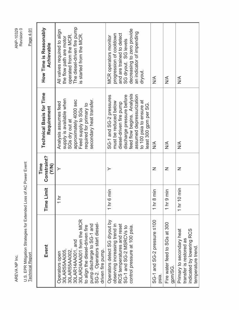
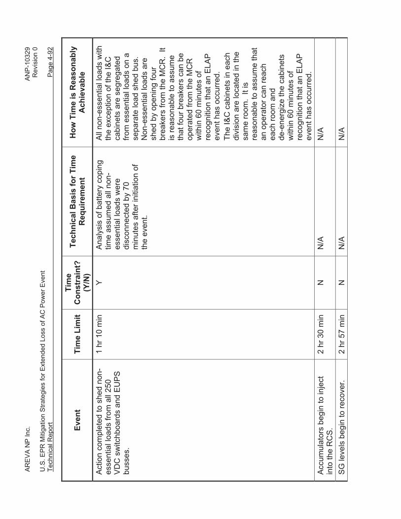
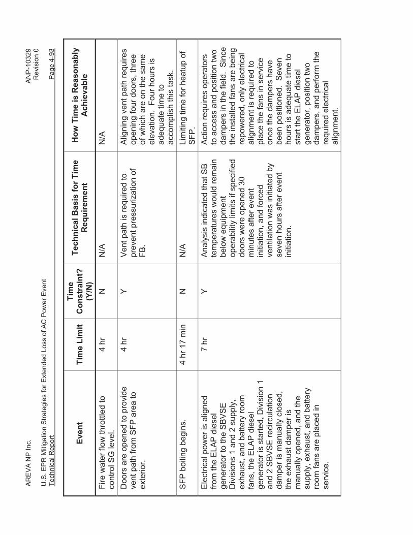
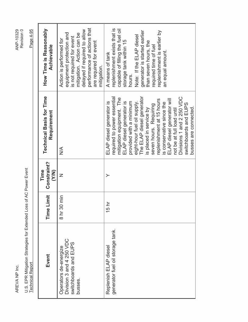
An overview of the mitigation strategies for these functional objectives is provided in
Table 4-3. Details of the mitigation strategies for each of these functional objectives are
provided in the following subsections.
AR
EV
A N
P In
c.
A
NP
-103
29
Rev
isio
n 0
U.S
. EP
R M
itiga
tion
Stra
tegi
es fo
r Ext
ende
d Lo
ss o
f AC
Pow
er E
vent
Te
chni
cal R
epor
t
Pag
e 4-
45
Tabl
e 4-
3—FL
EX C
apab
ility
– C
ore
Coo
ling
Sum
mar
y –
Mod
es 1
thro
ugh
5
Safe
ty F
unct
ion
Met
hod
Phas
e 1
Phas
e 2
and
3
Core Cooling
Rea
ctor
Cor
e C
oolin
g an
d H
eat
Rem
oval
(M
odes
1
thro
ugh
5 S
Gs
avai
labl
e)
• S
econ
dary
sid
e fe
ed
and
blee
d w
ith
dies
el-d
riven
fire
pum
p to
feed
SG
s vi
a E
FW
head
er.
• D
epre
ssur
ize
SG
s fo
r se
cond
ary
mak
eup.
•
Sus
tain
ed s
ourc
e of
m
akeu
p w
ater
.
• P
erm
anen
t pip
ing
from
sei
smic
ally
qu
alifi
ed d
iese
l-driv
en fi
re p
ump
to
EFW
hea
der.
• S
Gs
are
depr
essu
rized
usi
ng
MS
RTs
. •
SG
mak
eup
suffi
cien
t to
rest
ore
SG
le
vel w
ith in
stal
led
equi
pmen
t fo
llow
ing
SG
dry
out.
• Fi
re w
ater
sto
rage
tank
s an
d bu
ildin
g ar
e re
ason
ably
pro
tect
ed.
• P
erm
anen
t con
nect
ions
(prim
ary
and
alte
rnat
e) fo
r por
tabl
e, s
elf-
pow
ered
, SG
mak
eup
pum
p.
• P
orta
ble
mea
ns to
refil
l fire
wat
er
stor
age
tank
to e
xten
d ba
selin
e co
ping
. •
Por
tabl
e m
eans
to re
fill f
ire p
ump
dies
el ta
nks
and
lube
oil
to e
xten
d ba
selin
e co
ping
.
RC
S In
vent
ory
Con
trol/L
ong-
Te
rm
Sub
criti
calit
y
• Lo
w le
akag
e R
CP
se
als
and/
or b
orat
ed
high
pre
ssur
e R
CS
m
akeu
p re
quire
d.
• R
CP
SS
SS
lim
its R
CP
sea
l lea
kage
du
ring
initi
al e
vent
miti
gatio
n.
• A
ccum
ulat
or v
olum
e in
itial
ly
mai
ntai
ns R
CS
inve
ntor
y an
d bo
rate
s th
e R
CS
.
• P
erm
anen
t con
nect
ions
(prim
ary
and
alte
rnat
e) fo
r por
tabl
e, s
elf-
pow
ered
, hig
h pr
essu
re R
CS
m
akeu
p pu
mp.
•
Bor
ated
wat
er s
ourc
e is
por
tabl
e ta
nk m
ixed
on
site
, off-
site
sou
rce,
IR
WS
T, o
r ext
ra b
orat
ing
syst
em
(EB
S) t
anks
. K
ey R
eact
or
Par
amet
ers
• S
G le
vel.
• S
G p
ress
ure.
•
RC
S p
ress
ure.
•
RC
S te
mpe
ratu
re.
• In
stru
men
ts p
ower
ed b
y C
lass
1E
D
C b
us.
• D
C lo
ad s
hedd
ing
used
to e
xten
d ba
selin
e co
ping
.
• P
ower
Div
isio
ns 1
and
2 C
lass
1E
ba
tterie
s us
ing
eith
er th
e E
LAP
di
esel
gen
erat
or in
the
Fire
P
rote
ctio
n B
uild
ing
or b
y po
rtabl
e ge
nera
tors
.
AREVA NP Inc. ANP-10329 Revision 0 U.S. EPR Mitigation Strategies for Extended Loss of AC Power Event Technical Report Page 4-46
4.1.5.2.1 RCS Inventory Control
Adequate core cooling is provided by maintaining the liquid level in the reactor vessel
above the top of the fuel in the core (refer to Section 4.1.2). RCS inventory control is
challenged during an ELAP event by the loss of all AC powered RCS injection sources
and by the potential for increased RCP seal leakage resulting from overheating of the
RCP seals. Mitigation of the challenge to core cooling requires a source of makeup to
the RCS, as well as minimization of RCS inventory losses.
4.1.5.2.1.1 RCS Makeup
The reduction in RCS pressure resulting from primary to secondary heat transfer during
SG depressurization enables the accumulators to inject borated water for RCS
inventory makeup and reactivity control. Approximately 37,000 gallons of accumulator
inventory is available to make up for RCS contraction and leakage until pumped
injection can be placed into service.
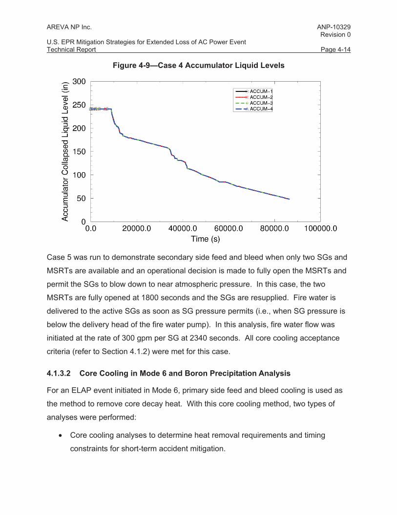
In Section 4.1.3.1, analyses were performed to characterize the RCS response to an
ELAP event initiated in Modes 1 through 5. These results indicated that accumulator
injection began at approximately two and a half hours into the event and continued until
approximately 24 hours without exhausting the accumulator inventory. These results
indicate that adequate time exists for installation and alignment of a source of pumped
injection for RCS makeup in Phase 2 (refer to simplified Figure 4-15).
An alternate supply source can be connected to the EBS discharge piping using a
portable pump. The suction source to the portable pump may be a portable borated
water supply or the IRWST. The U.S. EPR uses enriched boron. The equivalent boron
concentration of the portable borated water supply is in the range of 1700 ppm enriched
boron to 1900 ppm enriched boron. These values correspond to the minimum and
maximum Technical Specification limits for the IRWST and accumulators.
AREVA NP Inc. ANP-10329 Revision 0 U.S. EPR Mitigation Strategies for Extended Loss of AC Power Event Technical Report Page 4-47
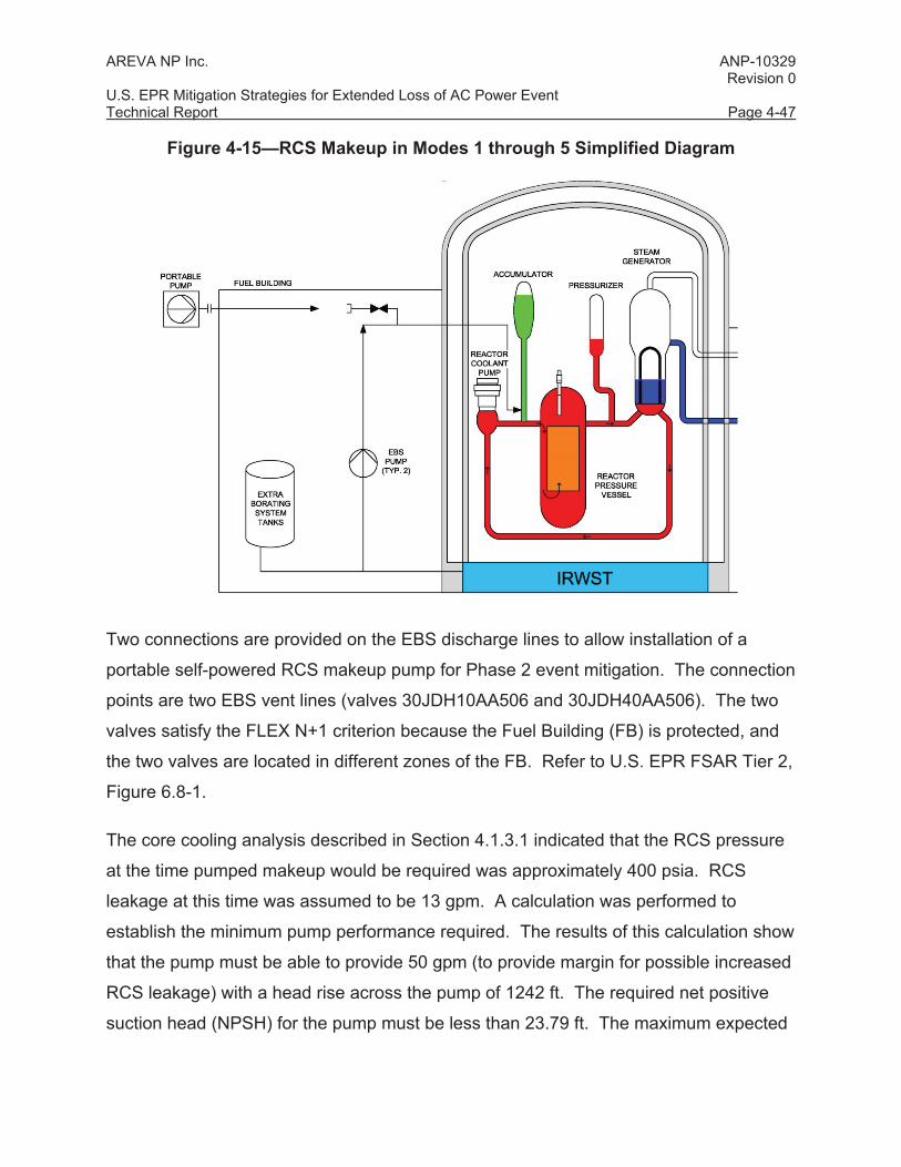
Figure 4-15—RCS Makeup in Modes 1 through 5 Simplified Diagram
Two connections are provided on the EBS discharge lines to allow installation of a
portable self-powered RCS makeup pump for Phase 2 event mitigation. The connection
points are two EBS vent lines (valves 30JDH10AA506 and 30JDH40AA506). The two
valves satisfy the FLEX N+1 criterion because the Fuel Building (FB) is protected, and
the two valves are located in different zones of the FB. Refer to U.S. EPR FSAR Tier 2,
Figure 6.8-1.
The core cooling analysis described in Section 4.1.3.1 indicated that the RCS pressure
at the time pumped makeup would be required was approximately 400 psia. RCS
leakage at this time was assumed to be 13 gpm. A calculation was performed to
establish the minimum pump performance required. The results of this calculation show
that the pump must be able to provide 50 gpm (to provide margin for possible increased
RCS leakage) with a head rise across the pump of 1242 ft. The required net positive
suction head (NPSH) for the pump must be less than 23.79 ft. The maximum expected
AREVA NP Inc. ANP-10329 Revision 0 U.S. EPR Mitigation Strategies for Extended Loss of AC Power Event Technical Report Page 4-48
pump discharge pressure under these conditions was calculated to be 548.4 psia. The
EBS vent valve lines used as connection points are sized at two inches to
accommodate the 50 gpm makeup flow rate.
If EBS Division 1 is used, the portable pump is connected to 30JDH10AA506. EBS
Train 1 containment isolation valve (30JDH10AA006) is opened, and either EBS Train 1
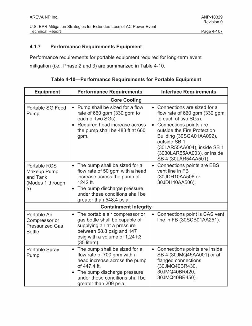
• Pump shall be sized for a flow rate of 660 gpm (330 gpm to each of two SGs).
• Required head increase across the pump shall be 483 ft at 660 gpm.
• Connections are sized for a flow rate of 660 gpm (330 gpm to each of two SGs).
• Connections points are outside the Fire Protection Building (30SGA01AA092), outside SB 1 (30LAR55AA004), inside SB 1 (3030LAR55AA003), or inside SB 4 (30LAR54AA501).
Portable RCS Makeup Pump and Tank (Modes 1 through 5)
• The pump shall be sized for a flow rate of 50 gpm with a head increase across the pump of 1242 ft.
• The pump discharge pressure under these conditions shall be greater than 548.4 psia.
• Connections points are EBS vent line in FB (30JDH10AA506 or 30JDH40AA506).
Containment Integrity Portable Air Compressor or Pressurized Gas Bottle
• The portable air compressor or gas bottle shall be capable of supplying air at a pressure between 58.8 psig and 147 psig with a volume of 1.24 ft3 (35 liters).
• Connections point is CAS vent line in FB (30SCB01AA251).
Portable Spray Pump
• The pump shall be sized for a flow rate of 700 gpm with a head increase across the pump of 447.4 ft.
• The pump discharge pressure under these conditions shall be greater than 209 psia.
• Connections points are inside SB 4 (30JMQ45AA001) or at flanged connections (30JMQ40BR430, 30JMQ40BR420, 30JMQ40BR450).
AREVA NP Inc. ANP-10329 Revision 0 U.S. EPR Mitigation Strategies for Extended Loss of AC Power Event Technical Report Page 4-108
Equipment Performance Requirements Interface Requirements Spent Fuel Pool Cooling
Portable Spent Fuel Pool Makeup Pump and Water Source
• The pump shall be sized for a flow rate of 500 gpm with a discharge head of 130 ft.
• Actual SFP makeup requirement for ELAP event is 140 gpm. This flow rate is enveloped 10 CFR 50.54 (hh)(2) requirement of 500 gpm.
• Connections points are outside FB (30KTC30AA074 or 30KTC30AA084).
Electrical and DC Load Shedding Portable ELAP Diesel Generators
• If one portable ELAP diesel generator is used to repower Divisions 1 and 2, the required output shall be at least 650 kW.
• If Divisions 1 and 2 are powered by separate portable generators, the required output for each shall be at least 350 kW.
• Output voltage shall be 480 VAC.
• Connections points are in SB (31BMB and 32BMB buses).
HVAC Portable Cooler • The cooler (air conditioner)
shall be sized to provide a minimum of 32,000 BTUs/hr of cooling to MCR.
• Hot exhaust from cooler condensing unit is directed to SB 3.
4.2 NTTF 7, Enhancing Spent Fuel Pool Makeup & Instrumentation
4.2.1 NTTF 7.1, Safety-Related Spent Fuel Pool Level Instrumentation
4.2.1.1 Overview
Recommendation 7.1 is a Tier 1 recommendation that resulted in the issuance of NRC
Order EA-12-051 (Reference 2). This order stated that Licensees must provide
sufficiently reliable instrumentation to monitor SFP water level and be capable of
withstanding design basis natural phenomena.
AREVA NP Inc. ANP-10329 Revision 0 U.S. EPR Mitigation Strategies for Extended Loss of AC Power Event Technical Report Page 4-109
4.2.1.2 Conformance
Consistent with the information in Attachment 3 to Order EA-12-051 (Reference 2), the
U.S. EPR addresses the requirements in Attachment 2 to Order EA-12-051 by providing
two physically separate and independent divisions of safety-related SFP level sensing
with two redundant wide range level sensor channels in each division. The instruments
measure the level from the top of the SFP normal operating range to below the top of
the fuel racks. This span provides indication of:
• A level that is adequate to support operation of the normal SFP cooling system.
• A level that is adequate to provide substantial radiation shielding for a person
standing on the SFP operating deck.
• A level where fuel remains covered and actions to implement makeup water
addition should no longer be deferred.
The SFP level instrumentation is safety-related and has the following design features:
• Seismic and environmental qualification of the instruments.
• Independent power supplies.
• Electrical isolation and physical separation between instrument divisions.
• Continuous display in the MCR.
• Routine calibration and testing.
In addition, the following requirements that are specified in Attachment 3 to Order EA-
12-051 are addressed in a manner consistent with JLD-ISG-2012-03 (Reference 12),
Order EA-12-051 (Reference 2), and NEI 12-02, Revision 1 (Reference 16), as
endorsed by JLD-ISG-2012-03.
Arrangement
The SFP includes four SFP wide range level sensors. The safety-related wide range
level sensors are Seismic Category I components. The sensors are located in separate
AREVA NP Inc. ANP-10329 Revision 0 U.S. EPR Mitigation Strategies for Extended Loss of AC Power Event Technical Report Page 4-110
corners, or recesses, of the SFP to provide reasonable protection against missiles and
debris.
Refer to U.S. EPR FSAR Tier 2, Table 3.2.2-1 and Section 9.1.3.6.
Qualification
The wide range level sensors and cabling for the wide range level instrument channels
are qualified to operate for a minimum period of seven days under the following
conditions:
• Radiological conditions for a normal refueling quantity of freshly discharged (100
hours) fuel with the SFP water level where fuel remains covered.
• Temperature of 212 °F and 100% relative humidity.
• Boiling water and/or steam environment.
• Concentrated borated water environment.
Refer to U.S. EPR FSAR Tier 2, Table 3.11-1.
Power Supplies
The primary instrument channels normally receive power from plant vital AC power.
Each of the two divisions of wide range level sensors includes the capability to connect
a sensor directly to a battery-operated portable indication device. The two portable
indication devices provide on demand push-button-activated indication of SFP level with
no dependence on other station power sources. Each portable indication device is
located in the associated division instrumentation and controls (I&C) room, which is
protected and accessible during normal operation, event, and post-event conditions.
The portable indication device batteries are maintained in a charged state during normal
operation with a minimum battery capacity of seven days of on-demand operation.
Refer to U.S. EPR FSAR Tier 2, Sections 9.1.3.1 and 9.1.3.3.2.
AREVA NP Inc. ANP-10329 Revision 0 U.S. EPR Mitigation Strategies for Extended Loss of AC Power Event Technical Report Page 4-111
Accuracy
The accuracy of the wide range level instrument channels is less than ±1 ft over their
total instrument range of 33 ft (from elevation +30’ 0” to +63’ 0”). This configuration
provides reasonable assurance that the instrument channel indication demonstrates
that the stored fuel is covered with water. Accuracy is maintained without recalibration
following a power interruption, change in power source, or connection of a battery-
powered indication device.
Refer to U.S. EPR FSAR Tier 2, Section 9.1.3.6.
Display
Continuous display of the SFP level is available in the MCR.
On-demand indication of the SFP level is available in the I&C rooms in
Divisions 1 and 4. On-demand display is provided by portable battery-powered
indication devices that can be operated independently of normal and emergency station
power sources.
Training
U.S. EPR U.S. EPR FSAR Tier 2, Section 13.2 discusses the U.S. EPR requirements
for development of a training programs for plant personnel. The training program will
demonstrate that the SFP instrumentation is maintained available and reliable in an
ELAP event. Personnel will be trained in the use and the provision of alternate power to
the safety-related level instrument channels.
4.2.2 NTTF 7.3, Plant Technical Specification
4.2.2.1 Overview
Recommendation 7.3 is a Tier 2 recommendation that requests that Plant Technical
Specifications require one train of emergency onsite electrical power to be operable for
SFP makeup/instrumentation when there is irradiated fuel in the SFP, regardless of
plant operating mode.
AREVA NP Inc. ANP-10329 Revision 0 U.S. EPR Mitigation Strategies for Extended Loss of AC Power Event Technical Report Page 4-112
4.2.2.2 Conformance
The EPR Plant Technical Specifications require one train of emergency onsite power to
be available to operate SFP makeup and instrumentation when there is irradiated fuel in
the SFP regardless of the plant operating mode.
Refer to U.S. EPR FSAR Tier 2, Chapter 16, Technical Specification 3.8.11.
4.2.3 NTTF 7.4, Seismically Qualified Spent Fuel Pool Spray System
4.2.3.1 Overview
Recommendation 7.4 is a Tier 2 recommendation that requests that a seismically
qualified means to spray water into SFPs be provided, including an easily accessible
connection to supply water, such as using a portable pump or pumper truck, at grade
level outside of the building.
4.2.3.2 Conformance
Spent Fuel Pool Spray (SFPS) System
The SFPS system is a subsystem of the Nuclear Island Drain and Vent System. The
SFPS system provides a spray cooling function and an alternate fill pipe for makeup to
the SFP. Refer to simplified Figure 4-20.
The SFPS system is a dry system consisting of two separate, redundant trains that are
physically located on opposite sides of the SFP. Piping is routed from ground elevation
to the SFP elevation through stairwells.
Each SFPS train is capable of being supplied water from four sources:
• Fire water distribution system connection within the FB.
• Fire water distribution system connection within either SB 1 (Train 1) or SB 4
(Train 2).
• A separate and independent hose connection, located on the exterior of the FB
at grade elevation, can be used to attach a pumper truck or portable pump.
AREVA NP Inc. ANP-10329 Revision 0 U.S. EPR Mitigation Strategies for Extended Loss of AC Power Event Technical Report Page 4-113
The SFPS system is classified as Supplemented Grade (NS-AQ) and
Seismic Category II. To ensure adequate functionality following a safe shutdown
earthquake (SSE), the following supplemental seismic requirements are imposed:
• For valves and piping - ANSI/ASME B31.1 (Reference 24).
• For other SSC – ASCE 43-05, “Seismic Design Criteria for Structures, Systems,
and Components in Nuclear Facilities” (Reference 23).
This seismic qualification strategy is consistent with the seismic qualification strategy
used for the non-safety-related fire protection system, as described in U.S. EPR FSAR
Tier 2, Section 9.5.1.
Also refer to U.S. EPR FSAR Tier 2, Section 9.3.3.2.1 and Figure 9.3.3-1.
4.3 NTTF 9.3, Enhanced Emergency Preparedness
A portion of Recommendation 9.3 is Tier 1, and requires that enhanced emergency
preparedness staffing and communications be addressed.
4.3.1 Overview
This section describes provisions for enhancing emergency preparedness as it relates
to staffing and communications associated with Recommendation 9.3, outlined in
Enclosure 5 of the March 12, 2012 letter "Request for information pursuant to Title 10 of
the Code of Federal Regulations 50.54(f) regarding Recommendations 2.1, 2.3, and
9.3, of the near-term task force review of insights from the Fukushima Daiichi accident,"
(Reference 9). The letter requested that an assessment of the COMS and equipment
used during an emergency event be provided to identify any enhancements that may be
needed to ensure communications are maintained during a large scale natural event.
AREVA NP Inc. ANP-10329 Revision 0 U.S. EPR Mitigation Strategies for Extended Loss of AC Power Event Technical Report Page 4-114
4.3.2 Conformance
4.3.2.1 Enhanced Emergency Plan Staffing and Communications
4.3.2.1.1 Communications
The U.S. EPR includes onsite COMS that are independent and diverse. The COMS for
the U.S. EPR FSAR is described in U.S. EPR FSAR Tier 2, Section 9.5.2.
As noted in U.S. EPR FSAR Tier 2, Section 9.5.2, the COMS consists of the following
subsystems:
• Portable wireless COMS.
• Digital telephone system.
• PA and alarm system.
• Sound-powered system.
• Emergency offsite communication.
• Security communication.
Each communication subsystem provides an independent mode of communications. A
failure of one subsystem does not affect the capability to communicate using the other
subsystem. These diverse COMS are independent of each other to provide effective
communications, including usage in areas exposed to high ambient noise in the plant.
As noted in U.S. EPR FSAR Tier 2, Section 9.5.2, electrical power from a Class 1E
standby power source is provided for the portable wireless COMS base station,
emergency offsite communication capability, and plant security communications. An
isolation device is placed between non-Class 1E COMS components and the Class 1E
power supply to provide the required independence per IEEE Std 384-1992. The
backup power supplies for other communication subsystems (with the exception of the
sound powered phone system) and components are either from integral DC power units
or other plant backup power supplies based on their operational significance and
AREVA NP Inc. ANP-10329 Revision 0 U.S. EPR Mitigation Strategies for Extended Loss of AC Power Event Technical Report Page 4-115
location. Isolation of the non-safety-related AC sources to the Class 1E uninterruptible
power supply is also provided as described in U.S. EPR FSAR Tier 2, Section 8.3.1.1.9.
U.S. EPR FSAR Tier 2, Section 9.5.2.1.3 discusses the requirements for emergency
response facilities and associated communication capabilities.
U.S. EPR FSAR Tier 2, Section 9.5.2.1.3 describes the offsite COMS that interfaces
with the onsite communication system, including type of connectivity, radio frequency,
normal and backup power supplies, and plant security system interface.
U.S. EPR FSAR Tier 2, Section 9.5.2.1.3 discusses the requirements for emergency
response facilities and associated communication capabilities.
4.3.2.1.2 Staffing
U.S. EPR FSAR Tier 2, Section 13.0 discusses requirements for adequate plant staff
size and technical competence.
AREVA NP Inc. ANP-10329 Revision 0 U.S. EPR Mitigation Strategies for Extended Loss of AC Power Event Technical Report Page 5-1
5.0 REFERENCES
1. NRC Order EA-12-049, “Order Modifying Licenses with Regard to Requirements for Mitigation Strategies for Beyond-Design-Basis External Events,” March 12, 2012.
2. NRC Order EA-12-051, “Order Modifying Licenses with Regard to Reliable Spent Fuel Pool Instrumentation,” March 12, 2012.
3. NEI 12-06, Revision 0, “Diverse and Flexible Coping Strategies (FLEX) Implementation Guide,” Nuclear Energy Institute, August 2012.
4. SECY-11-0093, “Recommendations for Enhancing Reactor Safety in the 21st Century, the Near-Term Task Force Review of Insights from the Fukushima Daiichi Accident,” July 12, 2011.
5. SECY-11-0124, “Recommended Actions to be Taken without Delay from the Near-Term Task Force Report,” September 9, 2011.
6. SECY-11-0137, “Prioritization of Recommended Actions to be Taken in Response to Fukushima Lessons Learned,” October 3, 2011.
7. SECY-12-0025, “Proposed Orders and Requests for Information in Response to Lessons Learned from Japan’s March 11, 2011, Great Tohoku Earthquake and Tsunami,” February 17, 2012.
8. SECY-12-0095, “Tier 3 Program Plans and 6-Month Status Update in Response to Lessons Learned from Japan’s March 11, 2011, Great Tohoku Earthquake and Subsequent Tsunami,” July 13, 2012.
9. NRC Letter, “Request for Information Pursuant to Title 10 of the Code of Federal Regulations 50.54(f) Regarding Recommendations 2.1, 2.3, and 9.3, of the Near-Term Task Force Review of Insights from the Fukushima Dai-Ichi Accident,” March 12 2012.
10. SECY-13-0020, “Third 6-Month Status Update on Response to Lessons Learned from Japan’s March 11, 2011, Great Tohoku Earthquake and Subsequent Tsunami,” February 14, 2013.
11. JLD-ISG-2012-01, “Compliance with Order EA-12-049, Order Modifying Licenses with Regard to Requirements for Mitigation Strategies for Beyond-Design-Basis External Events,” August 29, 2012.
12. JLD-ISG-2012-03, Revision 0, “Compliance with Order EA-12-051, Reliable Spent Fuel Pool Instrumentation,” August 2012.
13. NEI 12-02, Revision 1, “Industry Guidance for Compliance with NRC Order EA-12-051, To Modify Licenses with Regard to Reliable Spent Fuel Pool Instrumentation,” Nuclear Energy Institute, August 2012.
AREVA NP Inc. ANP-10329 Revision 0 U.S. EPR Mitigation Strategies for Extended Loss of AC Power Event Technical Report Page 5-2
14. NRC Letter to AREVA NP Inc., “Implementation of Fukushima Near-Term Task Force Recommendations,” ADAMS Accession Number - ML121040163, April 25, 2012.
15. SRM-12-0025, “Proposed Orders and Requests for Information in Response to Lessons Learned from Japan’s March 11, 2011, Great Tohoku Earthquake and Tsunami,” February 17, 2012.
16. ANP-10263(P)(A), “Codes and Methods Applicability Report for the U.S. EPR,” AREVA NP Inc., November 2007.
17. EMF-2328(P)(A), “PWR Small Break LOCA Evaluation Model, S-RELAP5 Based.”
18. BAW-10240(P) (A), “Incorporation of M5™ Properties in Framatome ANP Approved Methods,” Framatome ANP, Inc., August 2004.
19. BAW-10252PA-00, “Analysis of Containment Response to Pipe Ruptures using GOTHIC,” Framatome ANP, Inc., December 2005.
20. ANP-10299P, Revision 2, “Applicability of AREVA NP Containment Response Evaluation Methodology to the U.S. EPR™ for Large Break LOCA Analysis Technical Report,” AREVA NP Inc., December 2009.
21. Regulatory Guide 1.221, Revision 0, “Design-Basis Hurricane and Hurricane Missiles for Nuclear Power Plants,” October 2011.
22. ASCE 7-10, “Minimum Design Loads for Buildings and Other Structures,” American Society of Civil Engineers, 2010.
23. ASCE 43-05, “Seismic Design Criteria for Structures, Systems and Components in Nuclear Facilities,” American Society of Civil Engineers, 2005.
24. ANSI/ASME B31.1-2004, “Power Piping,” American National Standards Institute/The American Society of Mechanical Engineers, 2004.
25. NUREG-1628, “Staff Responses to Frequently Asked Questions Concerning Decommissioning of Nuclear Power Reactors”, Final Report, June 2000.
26. Regulatory Guide 1.189, Revision 1, “Fire Protection for Nuclear Power Plants,” March 2007.
27. NUMARC 87-00, Revision 1, “Guidelines and Technical Bases for NUMARC Initiatives Addressing Station Blackout at Light Water Reactors”, Nuclear Utility Management and Resources Council (now Nuclear Energy Institute), August 1991.