143
2014 Standard for Performance Rating of Variable Refrigerant Flow (VRF) Multi-split Air-conditioning and Heat Pump Equipment AHRI Standard 1230 with Addendum 1

2014 Standard for
Performance Rating of
Variable Refrigerant
Flow (VRF) Multi-split
Air-conditioning and
Heat Pump Equipment
AHRI Standard 1230 with Addendum 1

AHRI STANDARD 1230-2014 WITH
ADDENDUM 1,
Performance Rating of Variable Refrigerant Flow (VRF)
Multi-split Air-conditioning and Heat Pump Equipment
September 2017
Addendum 1 (dated June 2017) of AHRI Standard 1230-2014, changes AHRI Standard 1230-2014 as follows.
Changes have been incorporated (additions are shown by shading and deletions are shown by strikethroughs) into the already
published version of ANSI/AHRI Standard 1230-2010 with Addenda 1 and 2 that is now designated AHRI Standard 1230-
2014.
The changes are to the inside front cover, scope of the VRF certification program, and sections listed below.
Section 3. Definitions
All terms in this document shall follow the standard industry definitions established in the current edition of ASHRAE
Terminology of Heating, Ventilation, Air Conditioning and Refrigeration, unless otherwise defined in this section.
All terms in this document will follow the standard industry definitions in the ASHRAE Terminology website
(https://www.ashrae.org/resources--publications/free-resources/ashrae-terminology) unless otherwise defined in this section.
3.1 Standard Air. Air weighing 0.075 lb/ft3 [1.2 kg/m3] which approximates dry air at 70F [21C] and at a barometric pressure of 29.92 in Hg [101.3 kPa].
3.1 Airflow Setting(s). Programmed or wired control system configurations that control a fan to achieve discrete, differing
ranges of airflow—often designated for performing a specific function (e.g., cooling, heating, or constant circulation)—without
manual adjustment other than interaction with a user-operable control (i.e., a thermostat) that meets the manufacturer
specifications for installed-use. For the purposes of this standard, manufacturer specifications for installed-use are those found
in the product literature shipped with the unit.
3.2 Multi-Split Air-Conditioner. An encased, factory-made assembly or assemblies designed to be used as permanently
installed equipment to provide conditioned air to an enclosed space(s). It includes a prime source of refrigeration for cooling
and dehumidification and may optionally include other means for heating, humidifying, circulating and cleaning the air. It
normally includes multiple evaporator(s), compressor(s), and condenser(s). Such equipment may be provided in more than
one assembly, the separated assemblies of which are intended to be used together.
3.2.4 Nominal Capacity. The capacity value of the outdoor units published by the manufacturer in their catalogue or
Engineering Data. Nominal Capacity may be referred to using the following terms:
3.2.4.1 Nominal Cooling Capacity. The Nominal Cooling Capacity shall not be more that 105% of the rated
cooling capacity. The Nominal Cooling Capacity of each Indoor Unit shall be the published capacity when the
ratings are first established, and shall not be changed upon subsequent publications.

3.2.4.2 Nominal Heating Capacity. Nominal Capacity in heating mode.
3.4.7 Rated Capacity. The capacity achieved at the Standard Rating Conditions in Btu/h.
3.5 Ducted Systems. A multi-split air conditioner or Heat Pump system with only Indoor Units designed to be permanently
installed and deliver all conditioned air through ductwork.
3.8 Ground-Water Heat Pump. Water-to-air heat pump using water pumped from a well, lake, or stream functioning as a
heat source/heat sink. The temperature of the water is related to the climatic conditions and may vary from 41º to 77ºF [5° to 25°C] for deep wells.
3.9 Ground-Loop Heat Pump. Brine-to-air heat pump using a brine solution circulating through a subsurface piping loop
functioning as a heat source/heat sink. The heat exchange loop may be placed in horizontal trenches, vertical bores, or be
submerged in a body of surface water. (ANSI/ARI/ASHRAE ISO Standard 13256-1:1998) The temperature of the brine is
related to the climatic conditions and may vary from 23º to 104ºF [–5° to 40°C].
3.10 Multi-Split Heat Pump. One or more factory-made assemblies designed to be used as permanently installed equipment
to take heat from a heat source and deliver it to the conditioned space when heating is desired. It may be constructed to remove
heat from the conditioned space and discharge it to a heat sink if cooling and dehumidification are desired from the same
equipment. It normally includes multiple indoor conditioning coils, compressor(s), and outdoor coil(s). Such equipment may
be provided in more than one assembly, the separated assemblies of which are intended to be used together. The equipment
may also provide the functions of cleaning, circulating and humidifying the air.
3.8 Heat Pump. A kind of central air conditioner that utilizes an indoor conditioning coil, compressor, and refrigerant-to-
outdoor air heat exchanger to provide air heating, and may also provide air cooling, air dehumidifying, air humidifying, air
circulating, and air cleaning.
3.9 Heating Coefficient of Performance (COPH). A ratio of the Heating Capacity in watts to the power input values in watts
at any given set of Rating Conditions expressed in W/W. For heating COP, supplementary resistance heat shall be excluded.
3.12 Heating Unit. A component of a VRF Multi-Split System air conditioner or heat pump that is designed to transfer heat
between the refrigerant and the indoor air, and which consists of an indoor coil, a cooling mode expansion device, an air moving
device, and a temperature sensing device.
3.15 Mini-Split Air-Conditioners and Heat Pumps. Systems that have a single outdoor section and one or more indoor
sections. The indoor sections cycle on and off in unison in response to a single indoor thermostat (As defined by DOE, See
Appendix C, Paragraph 1.29).
3.16 Multiple-Split Air-Conditioners and Heat Pumps [a.k.a .Multi-Split Air Conditioners and Heat Pumps]. Systems that
have two or more indoor sections. The indoor sections operate independently and can be used to condition multiple zones in
response to multiple indoor thermostats (As defined by DOE, See Appendix C, Paragraph 1.30).
3.14 Indoor Unit. A separate assembly of a Split System (a service coil is not an Indoor Unit) that includes the features listed
in Sections 3.14.1, 3.14.2, 3.14.3, and 3.14.4; and may or may not include the features listed in Sections 3.14.5, 3.14.6, and
3.14.7.
3.14.1 An arrangement of refrigerant-to-air heat transfer coil(s) for transfer of heat between the refrigerant and the indoor air
3.14.2 A condensate drain pan
3.14.3 An air temperature sensing device
3.14.4 An integrated indoor blower (i.e. a device to move air including its associated motor). A separate designated
air mover that may be a furnace or a modular blower may be considered to be part of the Indoor Unit.
3.14.5 Sheet metal or plastic parts not part of external cabinetry to direct/route airflow over the coil(s).

3.14.6 A cooling mode expansion device
3.14.7 External cabinetry
3.15 Indoor Unit Model Family. A model family constituting exclusively of the following types of Non-ducted Indoor Units.
3.15.1 Ceiling suspended. A non-ducted indoor unit that is totally encased and is suspended below the ceiling.
3.15.2 Floor-mounted. A non-ducted Indoor Unit intended for being installed at floor level either enclosed in the wall
space in an uncased configuration or extended out from the wall in a cased configuration.
3.15.3 Wall-mounted. A non-ducted Indoor Unit that is attached to the wall with a cased configuration, sometimes
referred to as a high-wall unit.
3.15.4 Ceiling Cassettes. Non-ducted Indoor Units intended to be installed flush mounted with the ceiling. These indoor units can have configurations of indoor airflow coming from one, two, four, or circular direction.
3.16 Non-ducted Indoor Unit. An Indoor Unit designed to be permanently installed, mounted on room walls, floors and/or
ceilings, which directly heats or cools air within the conditioned space. Non-ducted Indoor Units consists of the following
types: Wall-mounted, Floor-mounted, Ceiling Suspended, and Ceiling Cassette (standard and compact).
3.18 Outdoor Unit. A separate assembly of a Split System that transfers heat between the refrigerant and the outdoor air or
refrigerant and water, and consists of an outdoor heat exchanger, compressor(s), an air moving device, and in addition for Heat
Pumps, may include a heating mode expansion device, reversing valve, and/or defrost controls; Water Source Heat Pumps may
not have an air movement device.
3.19 Outdoor Unit. A component of a split-system central air conditioner or heat pump that is designed to transfer heat
between refrigerant and air, or refrigerant and water, and which consists of an outdoor coil, compressor(s), an air moving device,
and in addition for heat pumps, a heating mode expansion device, reversing valve, and defrost controls.
3.23 Small-duct, High-velocity System. A heating and/or cooling product that contains a blower and indoor coil combination
that is designed for, and produces, at least 1.2 in H2O [300 Pa] of external static pressure when operated at the certified air
volume rate of 220-350 cfm [0.104 – 0.165 m3/s] per rated ton of cooling. When applied in the field, small-duct products use
high-velocity room outlets (i.e., generally greater than 1,000 fpm [5 m/s]) having less than 6.0 in2 [3,900 mm2] of free area.
3.22 Small-duct, High-velocity System (SDHV). Split System for which all Indoor Units are blower coil Indoor Units that produce at least 1.2 inches of water column of external static pressure when operated at the Full-load Air Volume Rate certified
by the manufacturer of at least 220 scfm per rated ton of cooling.
3.24 Split System (Split System Air-conditioner or Split System Heat Pump). Any air conditioner or Heat Pump that has at
least two separate assemblies connected with refrigerant piping when installed. One of these assemblies includes an Indoor
Unit that exchanges heat with the indoor air to provide heating or cooling, while one of the others includes an Outdoor Unit
that exchanges heat with water or the outdoor air. Split Systems may be either blower coil systems or coil-only systems.
3.24.1 Multi-split System (Multi-split Air-conditioner or Multi-split Heat Pump). Split System that has one Outdoor
Unit and two or more Indoor Units and/or blower coil Indoor Units connected with a single refrigerant circuit. The
Indoor Units operate independently and can condition multiple zones in response to at least two indoor thermostats or
temperature sensors. The Outdoor Unit operates in response to independent operation of the Indoor Units based on
control input of multiple indoor thermostats or temperature sensors, and/or based on refrigeration circuit sensor input
(e.g., suction pressure)
3.25 Stable Conditions. Balanced operating conditions in the indoor or outdoor section of the test chamber where the test unit
is maintaining Steady-state conditions and the test chamber is maintaining test room conditions within prescribed tolerances.
3.26 Standard Air. Air weighing 0.075 lb/ft3 which approximates dry air at 70F and at a barometric pressure of 29.92 in Hg.
3.27 Standard 4-way Cassette. A ceiling mounted Non-ducted Indoor Unit with air discharge louvers on 4 or more sides, a
central air return grill and main casing dimensions of 32” x 32” – 34” x 34”, and having the smallest coil volume of similar capacities in the Indoor Unit Model Family.

3.28 Steady-state Test. A test where the controlled test parameters are regulated to remain constant within the specified
tolerances while the unit operates continuously in the same mode.
3.30 Tested Combination (for air-cooled systems < 65,000 Btu/h). A sample basic model comprised of units that are
production units, or are representative of production units, of the basic model being tested. The tested combination shall have
the following features:
a. The basic model of a variable refrigerant flow system (“VRF system”) used as a Tested Combination shall consist of an outdoor unit (an outdoor unit can include multiple outdoor units that have been manifolded into a single
refrigeration system, with a specific model number) that is matched with between 2 and 12 a minimum of 2 and
a maximum of 5 indoor units.
b.5 All be subject to the same minimum external static pressure requirement while being configurable to
produce the same static pressure at the exit of each outlet plenum when manifolded as per Section 2.4.1 of 10
CFR Part 430, Subpart B, Appendix M.
3.31 Tested Combination (for air-cooled systems ≥ 65,000 Btu/h and water-source systems). A VRF base system having the
following features:
3.31.1 The base VRF system consists of an Outdoor Unit (an Outdoor Unit can include multiple Outdoor Units that
are manifolded into a single refrigeration system, with a specific model number) that is matched with a minimum of 2
and a maximum of 12 Indoor Units. Only ducted Indoor Units are used to determine the ratings for ducted base VRF
system. Only Non-ducted Indoor Units are used to determine the ratings for non-ducted base VRF system. When two or
more Outdoor Units are connected in a single refrigeration circuit, they will be considered as one Outdoor
Unit.
3.31.1.1 The Indoor Units defined below shall represent the Indoor Unit Model Families as defined by type
of Indoor Unit:
3.31.1.1.1 For Ducted Indoor Units, the tested combination shall represent the highest sales
volume (unit count) family, as determined by type of a manufacturer’s Ducted Indoor Unit offerings
e.g. low static, medium static, conventional static, etc.
3.31.1.1.2 Non-ducted Indoor Units consists of the following types: Wall-mounted, Floor- mounted, Ceiling Suspended, and Ceiling Cassette (standard and compact). To ensure common
testing characteristics all non-ducted Tested Combinations will use Standard 4-way Ceiling Cassette
Indoor Units with the smallest coil volume per Nominal Capacity Bucket. If a manufacturer does
not have Standard 4-way Cassettes then their highest sales volume (unit count) family of Non-ducted
Indoor Units (encompassing all types of manufacturer’s Non-ducted Indoor Unit offerings) shall be
used.
3.31.1.2 The summation of the Nominal Cooling Capacities of all Indoor Units shall be between 95% and
105% of the Rated Capacity (cooling) of the Outdoor Unit.
3.31.1.3 The largest Indoor Unit shall not have a Nominal Cooling Capacity greater than 50% of the Nominal
Cooling Capacity of the Outdoor Unit.
3.31.1.4 All Indoor Units shall be a manufactured standard product offering.
3.31.1.5 The models comprising the Tested Combination of Indoor Units from within the tested model
family must have the lowest nominal coil volume offered by the manufacturer with the same Nominal
Cooling Capacity as defined in Table 1. Coil volume is calculated as follows:
𝑁𝐶𝑉 = 𝐿𝑐 . 𝑊𝑐. 𝐷𝑐
𝑄𝑛𝑜𝑚
1

Where:
Dc = Depth of the coil, in
Lc = Indoor coil height, in NCV = Nominal Coil Volume, in3/Btu/h
Qnom = Nominal Cooling Capacity, Btu/h Wc = Indoor coil width, in
3.31.1.6 Where multiple non-ducted or ducted Indoor Unit models are offered in the same Nominal
Cooling Capacity range (refer to Nominal Cooling Capacity ranges for Tested Combination) and with the same
lowest nominal coil volume, the model with the lowest efficiency indoor fan motor (among those with the
lowest nominal coil volume) shall be used (highest fan motor input power at rated indoor airflow) for Standard
Ratings.
Table 1. Nominal Cooling Capacity Buckets
Nominal Cooling
Capacity Allowable Capacity Range
Tons Btu/h Btu/h (min) Btu/h (max)
0.46 5,500 4,500 6,499
0.63 7,500 6,500 8,499
0.79 9,500 8,500 10,499
1 12,000 10,500 13,499
1.25 15,000 13,500 16,499
1.5 18,000 16,500 19,999
2 24,000 20,000 26,999
2.5 30,000 27,000 32,999
3 36,000 33,000 38,999
3.5 42,000 39,000 44,999
4 48,000 45,000 50,999
4.5 54,000 51,000 56,999
5 60,000 57,000 62,999
6 72,000 63,000 77,999
7 84,000 78,000 89,999
8 96,000 90,000 101,999
3.30 Water-To-Air Heat Pump and/or Brine-to-Air Heat Pump. A heat pump which consists of one or more factory-made
assemblies which normally include an indoor conditioning coil with air-moving means, compressor(s), and refrigerant-to- water
or refrigerant-to-brine heat exchanger(s), including means to provide both cooling and heating, cooling-only, or heating-only
functions. When such equipment is provided in more than one assembly, the separated assemblies should be designed to be used together. Such equipment may also provide functions of sanitary water heating, air cleaning, dehumidifying, and
humidifying.
3.31 Water Loop Heat Pump. Water-to-air heat pump using liquid circulating in a common piping loop functioning as a heat
source/heat sink. The temperature of the liquid loop is usually mechanically controlled within a temperature range of 59°F
[15°C] to 104°F [40.0°C].
3.35 Water Source Heat Pump. A water-source Heat Pump is typically one of multiple units using fluid circulated in a
common piping loop as a heat source/heat sink. The temperature of the loop fluid is usually mechanically controlled within a
moderate temperature range. The Heat Pump consists of one or more factory-made assemblies which normally include an
indoor conditioning coil with air moving means, compressor(s) and refrigerant-to-water heat exchanger(s), including means to
provide both cooling and heating or cooling only functions. When such equipment is provided in more than one assembly, the
separated assemblies shall be designed to be used together, and the requirements of rating outlined in the standard are based

upon the use of matched assemblies. Any references to Water Source Heat Pumps in this Standard includes all capacities ≥
17,000 Btu/h.
3.35.1 Water-to-air Heat Pump and/or Brine-to-air Heat Pump. A Heat Pump which consists of one or more heat
source factory-made assemblies which normally include an indoor conditioning coil with air-moving means, at least one
Variable Speed Compressor(s), and refrigerant-to- water or refrigerant-to-brine heat exchanger(s), including means to
provide both cooling and heating, cooling-only, or heating-only functions. When such equipment is provided in more
than one assembly, the separated assemblies should be designed to be used together. Such equipment may also provide
functions of sanitary water heating, air cleaning, dehumidifying, and humidifying.
3.35.2 Water Loop Heat Pump. Water-to-air Heat Pump using liquid circulating in a common piping loop functioning
as a heat source/heat sink. The temperature of the liquid loop is usually mechanically controlled within a temperature
range of 59 °F to 104 °F.
3.35.3 Ground-Loop Heat Pump. Brine-to-air Heat Pump using a brine solution circulating through a subsurface
piping loop functioning as a heat source/heat sink. The heat exchange loop may be placed in horizontal trenches, vertical
bores, or be submerged in a body of surface water. (ANSI/ARI/ASHRAE ISO Standard 13256-1:1998) The temperature
of the brine is related to the climatic conditions and may vary from 23 °F to 104 °F.
3.35.4 Ground-water Heat Pump. Water-to-air Heat Pump using water pumped from a well, lake, or stream
functioning as a heat source/heat sink. The temperature of the water is related to the climatic conditions and may vary
from 41 °F to 77 °F for deep wells.
Section 5. Test Requirements
5.1 All Standard Ratings shall be generated either by a) tests conducted per Section 5.2 and in accordance with the test
methods and procedures as described in the rest of this standard and its appendices, or b) an Alternative Efficiency
Determination Method (AEDM) per Section 5.3.
5.1 All testing for Standard Ratings shall be conducted in accordance with the test methods and procedures as described in
this standard and its appendices.
Section 6. Rating Requirements 6.1 Standard Ratings. Standard Ratings shall be established at the Standard Rating Conditions specified in 6.1.3 or shall be
generated by an Alternative Efficiency Determination Method (AEDM). Any capacity, SEER, EER, COPH, IEER or HSPF
ratings of a system generated by the results of an AEDM shall be no higher than the result of the AEDM output (rounded per
Sections 6.1.1 and 6.1.2). Any AEDM used shall be created in compliance with the regulations specified in 10 CFR §429.70.
6.1.5.1.2 Cooling Full-load Air Volume Rate for Non-ducted Units. For non-ducted units, the
Cooling Full-load Air Volume Rate is the air volume rate that results during each test when the unit
is operated at an external static pressure of zero in H2O [zero Pa].
6.1.5.1.2 Airflow Settings for Non-ducted Unit. The Airflow Settings shall be such that all
airflow rates shall be the air volume rate that results during each test when the unit is operated at an
external static pressure of 0.00 in H2O, as controlled automatically by the system controls (no
manual adjustments shall be permitted). For each Indoor Unit, the airflow shall not exceed 55 scfm
per 1,000 Btu/h for the cooling tests. This limitation applies only to the cooling airflow provided
that the manufacturer does not change fan speed for the heating test. If the manufacturer changes
fan speed for the heating test, the limitation of 55 scfm per 1,000 Btu/h also applies to the heating
test and the manufacturer must use the cooling capacity for scfm determination.
6.1.5.1.3 Tolerance for Airflow Settings. The tolerance on system airflow for each indoor test
room shall be ± 5% of the rated airflow. If the measured airflow rate is outside of this tolerance, the
testing laboratory shall contact the manufacturer about potential issues with setup. If the analysis
indicates a setup issue, the issue shall be corrected and the test will be rerun. If the analysis indicates
a sample issue, the test(s) shall be run at the measured airflow rate achieved.
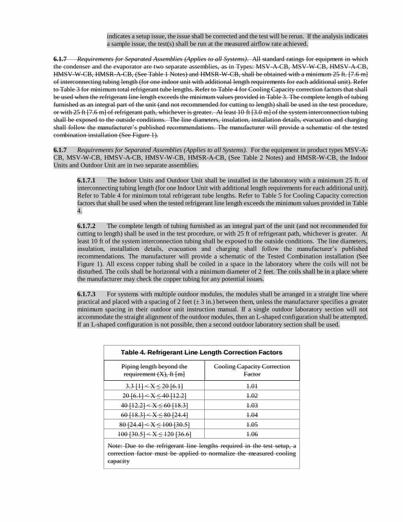
6.1.7 Requirements for Separated Assemblies (Applies to all Systems). All standard ratings for equipment in which
the condenser and the evaporator are two separate assemblies, as in Types: MSV-A-CB, MSV-W-CB, HMSV-A-CB,
HMSV-W-CB, HMSR-A-CB, (See Table 1 Notes) and HMSR-W-CB, shall be obtained with a minimum 25 ft. [7.6 m]
of interconnecting tubing length (for one indoor unit with additional length requirements for each additional unit). Refer
to Table 3 for minimum total refrigerant tube lengths. Refer to Table 4 for Cooling Capacity correction factors that shall
be used when the refrigerant line length exceeds the minimum values provided in Table 3. The complete length of tubing
furnished as an integral part of the unit (and not recommended for cutting to length) shall be used in the test procedure,
or with 25 ft [7.6 m] of refrigerant path, whichever is greater. At least 10 ft [3.0 m] of the system interconnection tubing
shall be exposed to the outside conditions. The line diameters, insulation, installation details, evacuation and charging
shall follow the manufacturer’s published recommendations. The manufacturer will provide a schematic of the tested
combination installation (See Figure 1).
6.1.7 Requirements for Separated Assemblies (Applies to all Systems). For the equipment in product types MSV-A-
CB, MSV-W-CB, HMSV-A-CB, HMSV-W-CB, HMSR-A-CB, (See Table 2 Notes) and HMSR-W-CB, the Indoor
Units and Outdoor Unit are in two separate assemblies.
6.1.7.1 The Indoor Units and Outdoor Unit shall be installed in the laboratory with a minimum 25 ft. of
interconnecting tubing length (for one Indoor Unit with additional length requirements for each additional unit).
Refer to Table 4 for minimum total refrigerant tube lengths. Refer to Table 5 for Cooling Capacity correction
factors that shall be used when the tested refrigerant line length exceeds the minimum values provided in Table
4.
6.1.7.2 The complete length of tubing furnished as an integral part of the unit (and not recommended for
cutting to length) shall be used in the test procedure, or with 25 ft of refrigerant path, whichever is greater. At
least 10 ft of the system interconnection tubing shall be exposed to the outside conditions. The line diameters,
insulation, installation details, evacuation and charging shall follow the manufacturer’s published
recommendations. The manufacturer will provide a schematic of the Tested Combination installation (See
Figure 1). All excess copper tubing shall be coiled in a space in the laboratory where the coils will not be
disturbed. The coils shall be horizontal with a minimum diameter of 2 feet. The coils shall be in a place where the manufacturer may check the copper tubing for any potential issues.
6.1.7.3 For systems with multiple outdoor modules, the modules shall be arranged in a straight line where
practical and placed with a spacing of 2 feet (± 3 in.) between them, unless the manufacturer specifies a greater
minimum spacing in their outdoor unit instruction manual. If a single outdoor laboratory section will not
accommodate the straight alignment of the outdoor modules, then an L-shaped configuration shall be attempted.
If an L-shaped configuration is not possible, then a second outdoor laboratory section shall be used.
Table 4. Refrigerant Line Length Correction Factors
Piping length beyond the
requirement (X), ft [m]
Cooling Capacity Correction
Factor
3.3 [1] < X ≤ 20 [6.1] 1.01
20 [6.1] < X ≤ 40 [12.2] 1.02
40 [12.2] < X ≤ 60 [18.3] 1.03
60 [18.3] < X ≤ 80 [24.4] 1.04
80 [24.4] < X ≤ 100 [30.5] 1.05
100 [30.5] < X ≤ 120 [36.6] 1.06
Note: Due to the refrigerant line lengths required in the test setup, a
correction factor must be applied to normalize the measured cooling
capacity
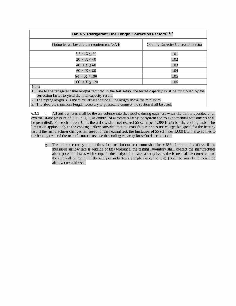
Table 5. Refrigerant Line Length Correction Factors1, 2, 3
Piping length beyond the requirement (X), ft Cooling Capacity Correction Factor
3.3 < X ≤ 20 1.01
20 < X ≤ 40 1.02
40 < X ≤ 60 1.03
60 < X ≤ 80 1.04
80 < X ≤ 100 1.05
100 < X ≤ 120 1.06
Note:
1. Due to the refrigerant line lengths required in the test setup, the tested capacity must be multiplied by the
correction factor to yield the final capacity result.
2. The piping length X is the cumulative additional line length above the minimum.
3. The absolute minimum length necessary to physically connect the system shall be used.
6.3.1 f. All airflow rates shall be the air volume rate that results during each test when the unit is operated at an
external static pressure of 0.00 in H2O, as controlled automatically by the system controls (no manual adjustments shall
be permitted). For each Indoor Unit, the airflow shall not exceed 55 scfm per 1,000 Btu/h for the cooling tests. This
limitation applies only to the cooling airflow provided that the manufacturer does not change fan speed for the heating
test. If the manufacturer changes fan speed for the heating test, the limitation of 55 scfm per 1,000 Btu/h also applies to
the heating test and the manufacturer must use the cooling capacity for scfm determination.
g. The tolerance on system airflow for each indoor test room shall be ± 5% of the rated airflow. If the
measured airflow rate is outside of this tolerance, the testing laboratory shall contact the manufacturer
about potential issues with setup. If the analysis indicates a setup issue, the issue shall be corrected and
the test will be rerun. If the analysis indicates a sample issue, the test(s) shall be run at the measured
airflow rate achieved.
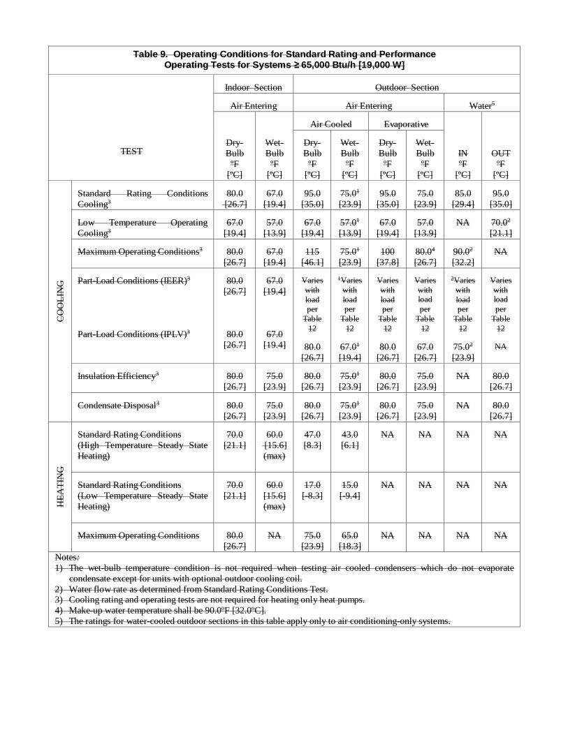
Table 9. Operating Conditions for Standard Rating and Performance Operating Tests for Systems ≥ 65,000 Btu/h [19,000 W]
TEST
Indoor Section
Outdoor Section
Air Entering
Air Entering
Water5
Dry-
Bulb
ºF
[oC]
Wet-
Bulb
ºF
[oC]
Air Cooled
Evaporative
IN
ºF
[oC]
OUT
ºF
[oC]
Dry-
Bulb
ºF
[oC]
Wet-
Bulb
ºF
[oC]
Dry-
Bulb
ºF
[oC]
Wet-
Bulb
ºF
[oC]
CO
OL
ING
Standard Rating Conditions
Cooling3
80.0
[26.7]
67.0
[19.4]
95.0
[35.0]
75.01
[23.9]
95.0
[35.0]
75.0
[23.9]
85.0
[29.4]
95.0
[35.0] Low Temperature Operating
Cooling3
67.0
[19.4]
57.0
[13.9]
67.0
[19.4]
57.01
[13.9]
67.0
[19.4]
57.0
[13.9]
NA
70.02
[21.1] Maximum Operating Conditions3
80.0
[26.7]
67.0
[19.4]
115
[46.1]
75.01
[23.9]
100
[37.8]
80.04
[26.7]
90.02
[32.2]
NA
Part-Load Conditions (IEER)3
Part-Load Conditions (IPLV)3
80.0
[26.7]
80.0
[26.7]
67.0
[19.4]
67.0
[19.4]
Varies
with
load per
Table
12
80.0
[26.7]
1Varies
with
load per
Table
12
67.01
[19.4]
Varies
with
load per
Table
12
80.0
[26.7]
Varies
with load
per
Table
12
67.0
[26.7]
2Varies
with
load per
Table
12
75.02
[23.9]
Varies
with load
per
Table
12
NA
Insulation Efficiency3
80.0
[26.7]
75.0
[23.9]
80.0
[26.7]
75.01
[23.9]
80.0
[26.7]
75.0
[23.9]
NA
80.0
[26.7] Condensate Disposal3
80.0
[26.7]
75.0
[23.9]
80.0
[26.7]
75.01
[23.9]
80.0
[26.7]
75.0
[23.9]
NA
80.0
[26.7]
HE
AT
ING
Standard Rating Conditions
(High Temperature Steady State
Heating)
70.0
[21.1]
60.0
[15.6]
(max)
47.0
[8.3]
43.0
[6.1]
NA
NA
NA
NA
Standard Rating Conditions
(Low Temperature Steady State
Heating)
70.0
[21.1]
60.0
[15.6]
(max)
17.0
[-8.3]
15.0
[-9.4]
NA
NA
NA
NA
Maximum Operating Conditions
80.0
[26.7]
NA
75.0
[23.9]
65.0
[18.3]
NA
NA
NA
NA
Notes:
1) The wet-bulb temperature condition is not required when testing air cooled condensers which do not evaporate
condensate except for units with optional outdoor cooling coil.
2) Water flow rate as determined from Standard Rating Conditions Test. 3) Cooling rating and operating tests are not required for heating only heat pumps.
4) Make-up water temperature shall be 90.0ºF [32.0ºC].
5) The ratings for water-cooled outdoor sections in this table apply only to air conditioning-only systems.

Table 10. Operating Conditions for Standard Rating and Performance Operating Tests for Systems ≥ 65,000 Btu/h8
TEST
Indoor Section
Outdoor Section
Air Entering
Air Entering
Water5
Dry-Bulb,
ºF
Wet-Bulb,
ºF
Air-source
Evaporative
IN,
ºF
OUT,
ºF
Dry-
Bulb, ºF
Wet-
Bulb,
ºF
Dry-
Bulb, ºF
Wet-
Bulb, ºF
CO
OL
ING
Standard Rating Conditions
Cooling3
80.0
67.0
95.0
75.01
95.0
75.0
86.0
95.0
Low Temperature Operating
Cooling3
67.0
57.0
67.0
57.01
67.0
57.0
NA
70.02
Maximum Operating Conditions3
80.0
67.0
115
75.01
100
80.04
90.02
NA
Part-Load Conditions (IEER)3, 6, 7
A. Air-to-Air
B. Air-to-Water
A. 80.0
B. 80.6
(100%
Load)
A. 67.0
B. 66.2
(100% Load)
95.0
(100%
Load)
74.5
(100%
Load)
86.0
(100%
Load)
A. 80.0
B. 80.6
(75%
Load)
A. 67.0
B. 66.2
(75%
Load)
81.5
(75%
Load)
66.2
(75%
Load)
73.5
(75%
Load)
A. 80.0
B. 80.6
(50%
Load)
A. 67.0
B. 66.2
(50%
Load)
68.0
(50%
Load)
57.5
(50%
Load)
62.0
(50%
Load)
A. 80.0
B. 80.6
(25%
Load)
A. 67.0
B. 66.2
(25%
Load)
65.0
(25%
Load)
52.8
(25%
Load)
55.0
(25%
Load)
Insulation Efficiency3
80.0
75.0
80.0
75.01
80.0
75.0
NA
80.0
Condensate Disposal3
80.0
75.0
80.0
75.01
80.0
75.0
NA
80.0
HE
AT
ING
Standard Rating Conditions
(High Temperature Steady State
Heating)
70.0
60.0
(max)
47.0
43.0
NA
NA
68
NA
Standard Rating Conditions
(Low Temperature Steady State
Heating)
70.0
60.0
(max)
17.0
15.0
NA
NA
NA
NA
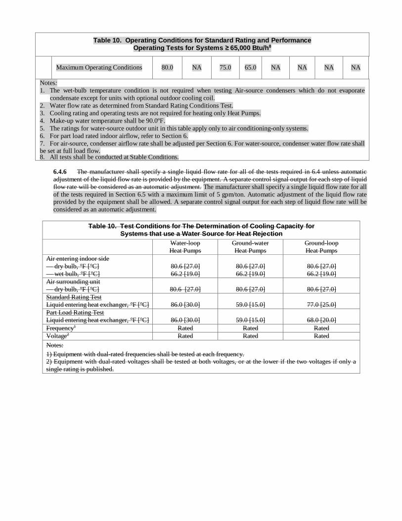
Table 10. Operating Conditions for Standard Rating and Performance Operating Tests for Systems ≥ 65,000 Btu/h8
Maximum Operating Conditions
80.0
NA
75.0
65.0
NA
NA
NA
NA
Notes:
1. The wet-bulb temperature condition is not required when testing Air-source condensers which do not evaporate
condensate except for units with optional outdoor cooling coil.
2. Water flow rate as determined from Standard Rating Conditions Test.
3. Cooling rating and operating tests are not required for heating only Heat Pumps.
4. Make-up water temperature shall be 90.0ºF.
5. The ratings for water-source outdoor unit in this table apply only to air conditioning-only systems.
6. For part load rated indoor airflow, refer to Section 6.
7. For air-source, condenser airflow rate shall be adjusted per Section 6. For water-source, condenser water flow rate shall be set at full load flow. 8. All tests shall be conducted at Stable Conditions.
6.4.6 The manufacturer shall specify a single liquid flow rate for all of the tests required in 6.4 unless automatic
adjustment of the liquid flow rate is provided by the equipment. A separate control signal output for each step of liquid
flow rate will be considered as an automatic adjustment. The manufacturer shall specify a single liquid flow rate for all
of the tests required in Section 6.5 with a maximum limit of 5 gpm/ton. Automatic adjustment of the liquid flow rate provided by the equipment shall be allowed. A separate control signal output for each step of liquid flow rate will be
considered as an automatic adjustment.
Table 10. Test Conditions for The Determination of Cooling Capacity for Systems that use a Water Source for Heat Rejection
Water-loop
Heat Pumps
Ground-water
Heat Pumps
Ground-loop
Heat Pumps
Air entering indoor side
— dry bulb, °F [°C]
— wet bulb, °F [°C]
80.6 [27.0]
66.2 [19.0]
80.6 [27.0]
66.2 [19.0]
80.6 [27.0]
66.2 [19.0]
Air surrounding unit
— dry bulb, °F [°C]
80.6 [27.0]
80.6 [27.0]
80.6 [27.0]
Standard Rating Test
Liquid entering heat exchanger, °F [°C]
86.0 [30.0]
59.0 [15.0]
77.0 [25.0]
Part Load Rating Test
Liquid entering heat exchanger, °F [°C]
86.0 [30.0]
59.0 [15.0]
68.0 [20.0]
Frequency1 Rated Rated Rated
Voltage2 Rated Rated Rated
Notes:
1) Equipment with dual-rated frequencies shall be tested at each frequency. 2) Equipment with dual-rated voltages shall be tested at both voltages, or at the lower if the two voltages if only a
single rating is published.
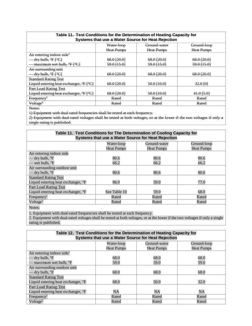
Table 11. Test Conditions for the Determination of Heating Capacity for Systems that use a Water Source for Heat Rejection
Water-loop
Heat Pumps
Ground-water
Heat Pumps
Ground-loop
Heat Pumps
Air entering indoor side1
— dry bulb, °F [°C]
— maximum wet bulb, °F [°C]
68.0 [20.0]
59.0 [15.0]
68.0 [20.0]
59.0 [15.0]
68.0 [20.0]
59.0 [15.0]
Air surrounding unit
— dry bulb, °F [°C]
68.0 [20.0]
68.0 [20.0]
68.0 [20.0]
Standard Rating Test
Liquid entering heat exchanger, °F [°C]
68.0 [20.0]
50.0 [10.0]
32.0 [0]
Part Load Rating Test
Liquid entering heat exchanger, °F [°C]
68.0 [20.0]
50.0 [10.0]
41.0 [5.0]
Frequency1 Rated Rated Rated
Voltage2 Rated Rated Rated
Notes:
1) Equipment with dual-rated frequencies shall be tested at each frequency.
2) Equipment with dual-rated voltages shall be tested at both voltages, or at the lower if the two voltages if only a
single rating is published.
Table 11. Test Conditions for The Determination of Cooling Capacity for Systems that use a Water Source for Heat Rejection
Water-loop
Heat Pumps
Ground-water
Heat Pumps
Ground-loop
Heat Pumps
Air entering indoor side
— dry bulb, °F
— wet bulb, °F
80.6
66.2
80.6
66.2
80.6
66.2
Air surrounding outdoor unit
— dry bulb, °F
80.6
80.6
80.6
Standard Rating Test
Liquid entering heat exchanger, °F
86.0
59.0
77.0
Part Load Rating Test
Liquid entering heat exchanger, °F
See Table 10
59.0
68.0
Frequency1 Rated Rated Rated
Voltage2 Rated Rated Rated
Notes:
1. Equipment with dual-rated frequencies shall be tested at each frequency. 2. Equipment with dual-rated voltages shall be tested at both voltages, or at the lower if the two voltages if only a single
rating is published.
Table 12. Test Conditions for the Determination of Heating Capacity for Systems that use a Water Source for Heat Rejection
Water-loop
Heat Pumps
Ground-water
Heat Pumps
Ground-loop
Heat Pumps
Air entering indoor side1
— dry bulb, °F
— maximum wet bulb, °F
68.0
59.0
68.0
59.0
68.0
59.0
Air surrounding outdoor unit
— dry bulb, °F
68.0
68.0
68.0
Standard Rating Test
Liquid entering heat exchanger, °F
68.0
50.0
32.0
Part Load Rating Test
Liquid entering heat exchanger, °F NA
NA
NA
Frequency1 Rated Rated Rated
Voltage2 Rated Rated Rated

Table 12. Test Conditions for the Determination of Heating Capacity for Systems that use a Water Source for Heat Rejection
Notes:
1. Equipment with dual-rated frequencies shall be tested at each frequency.
2. Equipment with dual-rated voltages shall be tested at both voltages, or at the lower if the two voltages if only a single
rating is published.
6.5 Part-Load Rating. Integrated Part-Load Value (IPLV) is in effect until January 1, 2010. See Appendix H for the method
and calculation of IPLV. Effective January 1, 2010, all units ≥ 65000 Btu/h [19,000W] rated in accordance with this standard shall include an Integrated Energy Efficiency Ratio (IEER).
6.5.1 Part-load Rating Conditions. Test conditions for part-load ratings shall be per Table 9. Any water flow required
for system function shall be at water flow rates established at (full load) Standard Rating Conditions. Capacity reduction
means may be adjusted to obtain the specified step of unloading. No manual adjustment of indoor and outdoor airflow
rates from those of the Standard Rating Conditions shall be made. However, automatic adjustment of airflow rates by
system function is permissible.
6.5.2 General. The IEER is intended to be a measure of merit for the part-load performance of the unit. Each
building may have different part-load performance due to local occupancy schedules, building construction, building
location and ventilation requirements. For specific building energy analysis an hour-by-hour analysis program should
be used.
6.5.3 Integrated Energy Efficiency Ratio (IEER). For equipment covered by this standard, the IEER shall be
calculated using test derived data and the following formula.
IEER = (0.020 · A) + (0.617 · B) + (0.238 · C) + (0.125 · D)
Where:
A = EER at 100% net capacity at AHRI standard rating conditions
B = EER at 75% net capacity and reduced ambient (see Table 12)
C = EER at 50% net capacity and reduced ambient (see Table 12)
D = EER at 25% net capacity and reduced ambient (see Table 12)
The IEER rating requires that the unit efficiency be determined at 100%, 75%, 50% and 25% load (net capacity) at the
conditions specified in Table 12. If the unit, due to its capacity control logic cannot be operated at the 75%, 50%, or
25% load points, then the 75%, 50%, or 25% EER is determined by plotting the tested EER vs. the percent load and
using straight line segments to connect the actual performance points. Linear interpolation is used to determine the EER
at 75%, 50% and 25% net capacity. For the interpolation, an actual capacity point equal to or less than the required
rating point must be used to plot the curves. Extrapolation of the data is not allowed.
If the unit has a variable indoor airflow rate, the external static pressure shall remain constant at the full load rating point
as defined in Table 12, but the airflow rate should be adjusted to maintain the unit leaving dry bulb air temperature measured at the full load rating point.
If the unit cannot be unloaded to the 75%, 50%, or 25% load then the unit should be run at the minimum step of unloading
at the condenser conditions defined for each of the rating load points and then the efficiency should be adjusted for cyclic
performance using the following equation.
D C CF IF CT
LF·Net CapacityEER
LF·[C ·(P P )] P P
(15)
Where:
Net Capacity = Measured net capacity at the lowest machine unloading point operating at the desired part
load rating condition, indoor measured capacity minus fan heat, Btu/h
PC = Compressor power at the lowest machine unloading point operating at the desired part load
rating condition, watts
PCF = Condenser fan power, if applicable at the minimum step of unloading at the desired part

load rating condition, watts
PIF = Indoor fan motor power at the fan speed for the minimum step of capacity, watts
PCT = Control circuit power and any auxiliary loads, watts
CD = Degradation coefficient to account for cycling of the compressor for capacity less than the
minimum step of capacity. CD should be determined using the following equation.
DC ( 0.13·LF) 1.13 (16)
Where:
LF = Fractional “on” time for last stage at the desired load point.
%Load·(Full Load Unit Net Capacity)
100LF
Part Load Unit Net Capacity
(17)
%Load = The standard rating point i.e. 75%, 50%, 25%.
Table 12. IEER Part-Load Rating Conditions
Conditions F C
Indoor Air
Return Air Dry-Bulb Temperature
Return Air Wet-Bulb Temperature
Indoor Airflow Rate
80.0
67.0
Note 1
26.7
19.4
Note 1
Condenser (Air Cooled)
Entering Dry-Bulb Temperature Outside
Air Temperature (OAT)
Condenser Airflow Rate (cfm)
For % Load > 44.4%,
OAT = 0.54 · % Load + 41
For % Load ≤ 44.4%, OAT = 65.0
Note 2
For % Load > 44.4%,
OAT = 0.30 · % Load + 5.0
For % Load ≤ 44.4%, OAT = 18.3
Note 2
Condenser (Water Cooled)
Condenser Entering Water Temperature
(EWT)
Condenser Water Flow Rate (gpm)
For % Load > 34.8%,
EWT = 0.460 · % LOAD + 39
For % Load ≤ 34.8%, EWT = 55.0
full load flow
For % Load > 34.8% ,
EWT = 0.256 · % LOAD + 3.8
For % Load ≤ 34.8%, EWT = 12.8
full load flow
Condenser (Evaporatively Cooled)
Entering Wet-Bulb Temperature (EWB)
For % Load > 36.6%,
EWB = 0.35 · % Load + 40
For % Load ≤ 36.6%, EWB = 52.8
For % Load > 36.6%,
EWB = 0.19 · % Load + 4.4
For % Load ≤36.6%, EWB = 11.6
Notes:
1 For fixed speed indoor fans the airflow rate should be held constant at the full load airflow rate. For units using
discrete step fan control, the fan speed should be adjusted as specified by the controls.
2 Condenser airflow should be adjusted as required by the unit controls for head pressure control.
6.5.4 Example Calculations.
Example 1 - Unit with proportional capacity control and can be run at the 75%, 50%, and 25% rating points and has a
fixed speed indoor fan.
Assume that the unit has the following measured capacity:

Using the measured performance you can then calculate the IEER as follows:
IEER (0.020 10.92) (0.617 11.13) (0.238 10.35) (0.125 7.39) 10.48
Example 2 – Unit has a single compressor with a fixed speed indoor fan.
Assume the unit has the following measured capacity:
Stage Ambient Actual % Load
Net Cap Cmpr (P C )
Cond (P CF )
Indoor (P IF )
Control (P CT )
EER
(°F) (Net Cap) Btu/h W W W W Btu/W 1 95.0 100 114,730 8,707 650 1,050 100 10.92 1 81.5 104.8 120,264 7,623 650 1,050 100 12.76 1 68.0 108.6 124,614 6,653 650 1,050 100 14.74 1 65.0 109.1 125,214 6,450 650 1,050 100 15.18
The unit cannot unload to the 75%, 50% or 25% points so tests were run with the compressor on at the ambient
temperatures specified for 75%, 50%, and 25%
Calculate the Load Factor (LF) and the CD factors and then calculate the adjusted performance for the 75%, 50%, and
25% points and then calculate the IEER.
Stage Ambient Actual %
Load
Net Cap Cmpr
(PC)
Cond
(PCF)
Indoor
(PIF)
Control
(PCT)
EER
(F) (Net Cap) Btu/h W W W W Btu/W
4 95.0 100 114,730 8,707 650 1,050 100 10.92
3 81.5 75 86,047 5,928 650 1,050 100 11.13
2 68.0 50 57,365 3,740 650 1,050 100 10.35
1 65.0 25 28,682 2,080 650 1,050 100 7.39

The following is an example of the CD calculation for the 50% point:
50·114,730
100LF .460
124,614
DC ( 0.13·.460) 1.13 1.070
50%
.460 124,614EER 12.08
.460 (1.070 (6,653 650)) 1,050 100
IEER=(0.020 10.92)+(0.617 11.81)+(0.238 12. 08)+(0.125 9.76)=11.60
Example 3 – Unit has two refrigeration circuits with one compressor in each circuit and two stages of capacity with a fixed speed indoor fan.
Assume the unit has the following measured performance.
The unit can unload to get to the 75% point, but cannot unload to get to the 50% and 25% points so additional tests are
run at the 50% and 25% load ambients with the stage 1 loading.
Calculate the 50% and 25% load factors and DC factors as shown below.
Calculate the Load Factor (LF) and the DC factors and then calculate the adjusted performance for the 75%, 50%, and
25% points and then calculate the IEER:
IEER=(0.020 10.92)+(0.617 12.05)+(0.238 12. 60)+(0.125 10.04)=11.91
IEER=(0.020 10.92)+(0.617 12.05)+(0.238 12. 60)+(0.125 10.04)=11.91
Example 4 – Unit has three refrigeration circuits with one compressor in each circuit and three stages of capacity with a
fixed speed indoor fan.
Assume the unit has the following measured performance.
Stage Ambient Actual %
Load
Net Cap Cmpr
(PC)
Cond
(PCF)
Indoor
(PIF)
Control
(PCT)
EER
(F) (Net Cap) Btu/h W W W W Btu/W
2 95.0 100 114,730 8,707 650 1,050 100 10.92
1 71.0 55.5 63,700 3,450 325 1,050 100 12.93
1 68.0 55.9 64,100 3,425 325 1,050 100 13.08
1 65.0 56.1 64,400 3,250 325 1,050 100 13.63
Stage Ambient Actual %
Load
Net Cap Cmpr
(PC)
Cond
(PCF)
Indoor
(PIF)
Control
(PCT)
EER CD LF
(F) (Net Cap) Btu/h W W W W Btu/W
2 95.0 100.0 114,730 8,707 650 1,050 100 10.92
1 71.0 55.5 63,700 3,450 325 1,050 100 12.93
75.0 12.05
1 68.0 55.9 64,100 3,425 325 1,050 100 13.08
50.0 Adjusted for Cyclic Performance 12.60 1.014 0.895
1 65.0 56.1 64,400 3,250 325 1,050 100 13.63
25.0 10.04 1.072 0.445
interpolation
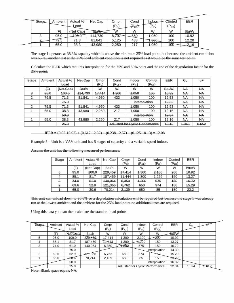
The stage 1 operates at 38.3% capacity which is above the minimum 25% load point, but because the ambient condition
was 65 °F, another test at the 25% load ambient condition is not required as it would be the same test point.
Calculate the IEER which requires interpolation for the 75% and 50% point and the use of the degradation factor for the
25% point.
Stage Ambient Actual % Load
Net Cap Cmpr (PC)
Cond (PCF)
Indoor (PIF)
Control (PCT)
EER CD LF
(F) (Net Cap) Btu/h W W W W Btu/W NA NA
3 95.0 100.0 114,730 17,414 1,300 1,050 100 10.92 NA NA
2 79.5 71.3 81,841 4,950 433 1,050 100 12.53 NA NA
75.0 interpolation 12.32 NA NA
2 79.5 71.3 81,841 4,950 433 1,050 100 12.53 NA NA
1 65.0 38.3 43,980 2,250 217 1,050 100 12.16 NA NA
50.0 interpolation 12.57 NA NA
1 65.0 38.3 43,980 2,250 217 1,050 100 12.16 NA NA
25.0 Adjusted for Cyclic Performance 10.13 1.045 0.652
IEER = (0.02·10.92) + (0.617·12.32) + (0.238·12.57) + (0.125·10.13) = 12.08
Example 5 – Unit is a VAV unit and has 5 stages of capacity and a variable speed indoor.
Assume the unit has the following measured performance.
Stage Ambient Actual % Load
Net Cap Cmpr (PC)
Cond (PCF)
Indoor (PIF)
Control (PCT)
EER
(F) (Net Cap) Btu/h W W W W Btu/W
5 95.0 100.0 229,459 17,414 1,300 2,100 200 10.92
4 85.1 81.7 187,459 11,444 1,300 1,229 150 13.27
3 74.0 61.0 140,064 6,350 1,300 575 150 16.72
2 69.6 52.9 121,366 6,762 650 374 150 15.29
1 65.0 30.6 70,214 2,139 650 85 150 23.2
This unit can unload down to 30.6% so a degradation calculation will be required but because the stage 1 was already
run at the lowest ambient and the ambient for the 25% load point no additional tests are required.
Using this data you can then calculate the standard load points.
Note: Blank space equals NA.
Stage Ambient Actual %
Load
Net Cap Cmpr
(PC)
Cond
(PCF)
Indoor
(PIF)
Control
(PCT)
EER
(F) (Net Cap) Btu/h W W W W Btu/W
3 95.0 100.0 114,730 8,707 650 1,050 100 10.92
2 79.5 71.3 81,841 5,125 433 1,050 100 12.20
1 65.0 38.3 43,980 2,250 217 1,050 100 12.16
Stage Ambient Actual %
Load
Net Cap Cmpr
(PC)
Cond
(PCF)
Indoor
(PIF)
Control
(PCT)
EER CD LF
(F) (Net Cap) Btu/h W W W W Btu/W
5 95.0 100.0 229,459 17,414 1,300 2,100 200 10.92
4 85.1 81.7 187,459 11,444 1,300 1,229 150 13.27
3 74.0 61.0 140,064 6,350 1,300 575 150 16.72
75.0 14.39
2 69.6 52.9 121,366 6,762 650 374 150 15.29
1 65.0 30.6 70,214 2,139 650 85 150 23.22
50.0 16.32
25.0 Adjusted for Cyclic Performance 22.34 1.024 0.817
interpolation
interpolation

With this you can then calculate the IEER:
IEER = (0.02·10.92) + (0.617·14.39) + (0.238·16.32) + (0.125·22.34) = 15.78
6.5 Integrated Energy Efficiency Ratio (IEER) for Air-cooled Systems ≥ 65,000 Btu/h and Water-source Systems. The IEER
has been developed to represent a single metric for the annualized performance of the mechanical cooling system. It is based
on a volume weighted average of 3 building types and 17 climate zones and includes 4 rating points at 100%, 75%, 50% and
25% load at condenser conditions seen during these load points. It includes all mechanical cooling energy, fan energy and
other energy required to deliver the mechanical cooling, but excludes operating hours seen for just ventilation, economizer operation and does not include system options like demand ventilation, supply air reset, energy recovery and other system
options that might be applied on a job. The purpose of the metric is to allow for comparison of mechanical cooling systems
at a common industry metric set of conditions. It is not intended to be a metric for prediction of building energy use for the
HVAC systems.
Building energy consumption varies significantly based on many factors including, but not limited to, local occupancy
schedules, ambient conditions, building construction, building location, ventilation requirements and added features like
economizers, energy recovery, evaporative cooling, etc. IEER is comparative metric representing the integrated full load and
part load annualized performance of the mechanical cooling of the air- conditioning unit over a range of operating conditions.
It does not include performance of hybrid system features like economizers, energy recovery and heat reclaim. IEER is not
intended to be a predictor of the annual energy consumption of a specific building in a given climate zone. To more accurately
estimate energy consumption of a specific building an energy analysis using an hour-by-hour analysis program should be
performed for the intended building using the local weather data.
6.5.1 IEER Requirements. For units covered by this standard, the IEER shall be calculated using test data or AEDM
results and Equation 16.
𝐼𝐸𝐸𝑅 = (0.020 ∙ 𝐴) + (0.617 ∙ 𝐵) + (0.238 ∙ 𝐶) + (0.125 ∙ 𝐷) 16
Where:
A = EER at 100% Capacity at AHRI Standard Rating Conditions (see Table 10)
B = EER at 75% Capacity and reduced condenser temperature (see Table 10)
C = EER at 50% Capacity and reduced condenser temperature (see Table 10) D = EER at 25% Capacity and reduced condenser temperature (see Table 10)
The IEER rating requires that the unit efficiency be determined at 100%, 75%, 50%, and 25% Percent Load at the
conditions specified in Table 10 and at the part load rated airflow, if different than the full load rated airflow.
The EER at 100% Capacity is the Standard Energy Efficiency Ratio. No additional test at 100% Cooling Capacity is
required.
6.5.2 Rating Adjustments. The IEER shall be determined at the 4 ratings loads and condenser conditions as defined
in Table 10. If the unit is not capable of running at the 75%, 50% or 25% load then Section 6.5.3 shall be followed to
determine the rating at the required load.
6.5.2.1 Interpolation. If the units cannot run at the 75%, 50% or 25% points within a tolerance of ±3% but
is capable of running at load above and below the rating load of 75%, 50% or 25% interpolation of the test
points shall be used to determine the EER rating at the 75%, 50% or 25% loads.
Note: In this edition of the AHRI Standard 1230, the part load rating condenser temperatures have been fixed at the 100%, 75%, 50% and 25% values shown in Table 10. In AHRI Standard 1230-2010 with Addendum 2,
these were a function of the actual load. This change does not impact the units that can run at the 75%, 50%,
and 25% load conditions; however, for interpolating ratings the condenser temperature is now fixed at the 75%,
50% and 25% rating points. As a result, two tests at different loads above and below the rating point shall be
used for interpolating ratings. For example, if the unit is an air-source unit and the rating at a 75% load is being
determined, but the unit can only run at 80% load and 60% load, then the unit can be run at those percent part
loads at the same outdoor air temperature and the 75% rating can interpolated (see Figure 2). Figure 2 also

shows the difference between the AHRI Standard 1230-2010 with Addendum 2 and this edition.
Figure 2. Example Revised Part Load Ambient Conditions for Interpolation
6.5.2.2 Degradation. If the unit cannot be unloaded to the 75%, 50%, or 25% load then the unit shall be run
at the minimum step of unloading and minimum rated indoor airflow at the condenser conditions defined for
each of the rating Percent Load IEER points listed in Table 10 and then the part load EER shall be adjusted for
cyclic performance using Equation (17).
𝐸𝐸𝑅 =𝐿𝐹
𝐿𝐹×[𝐶𝐷×(𝑃𝐶+𝑃𝐶𝐷)]+𝑃𝐶𝑇 17
Where:
CD = The degradation coefficient to account for cycling of the compressor for capacity less than
the minimum step of capacity. CD shall be determined using Equation 18.
PC = Compressor power at the lowest machine unloading point operating at the desired part load
rating condition, watts
PCD = Condenser Section power, if applicable at the desired part load rating condition, watts. For
Air-source and evaporatively cooled units this power is the power of the fans and pumps. PCT = Control circuit power and any auxiliary loads, watts
𝐶𝐷 = (−0.13 ∙ 𝐿𝐹) + 1.13 18
Where:
LF = Fractional “on” time for last stage at the desired load point, noted in Equation 19.
𝐿𝐹 =(𝑃𝑒𝑟𝑐𝑒𝑛𝑡 𝐿𝑜𝑎𝑑
100⁄ ) ∙𝐹𝑢𝑙𝑙 𝐿𝑜𝑎𝑑 𝑁𝑒𝑡 𝐶𝑎𝑝𝑎𝑐𝑖𝑡𝑦
𝑃𝑎𝑟𝑡 𝐿𝑜𝑎𝑑 𝑁𝑒𝑡 𝐶𝑎𝑝𝑎𝑐𝑖𝑡𝑦 19
6.5.3 Procedure for Calculating IEER. The IEER shall be calculated using data and the following procedures.
For test purposes, test units shall be provided with manual means to adjust the unit refrigeration capacity in steps no
greater than 5% of the full load Rated Capacity by adjusting variable capacity compressor(s) capacity and or the stages of refrigeration capacity.
70
72
74
76
78
80
82
84
86
88
90
55% 60% 65% 70% 75% 80% 85%
Air
-so
urc
e O
utd
oo
r A
ir T
em
per
atu
re (F
)
% Load
AHRI 1230-2010 AHRI 1230-2016 Rating Point B (75%)
AHRI 1230-2014 with Addendum 1

6.5.3.1 The following sequential steps shall be followed.
6.5.3.1.1 For part load rating tests, the unit shall be configured per the manufacturer’s
instructions, including setting of stages of refrigeration and variable capacity compressor loading
percent for each of the part load rating points. The stages of refrigeration and variable capacity
compressor loading percent that result in capacity closest to the desired part load rating point of
75%, 50%, or 25%.
6.5.3.1.2 The condenser entering temperature shall be adjusted per the requirements of Table
11 and be within tolerance as defined in ASHRAE Standard 37 Table 2b.
6.5.3.1.3 The indoor airflow and static shall be adjusted per Section 6.
6.5.3.1.4 If the measured part load rating capacity ratio is within ±3%, based on the full load
measured test Cooling Capacity, above or below the part load capacity point, the EER at each load
point shall be used to determine IEER without any interpolation.
6.5.3.1.5 If the unit, due to its capacity control logic cannot be operated at the 75%, 50%, or
25% Percent Load within 3%, then an additional rating point(s) is required and the 75%, 50%, or
25% EER is determined by using linear interpolation. Extrapolation of the data is not allowed.
6.5.3.2 The additional test point(s) for interpolations shall be run as follows:
6.5.3.2.1 The ambient test conditions shall be within tolerances defined in ASHRAE Standard
37 of the specified ambient in Table 7 based on the IEER rating point of 75%, 50% or 25%.
Note: The condenser temperature shall be fixed for the two interpolation rating points at the values
listed in Table 10.
6.5.3.2.2 The indoor airflow shall be set as specified by the manufacturer and as required by
Section 6.
6.5.3.2.3 The stages of refrigeration capacity shall be increased or decreased within the limit of
the controls and until the measured part load is closest to the IEER percent part load rating point is
obtained.
Note: For example, to obtain a 50% rating point for a unit having test points at both 60% and 70%,
the 60% test point shall be used.
6.5.3.2.4 The measured part load capacity of the second test point shall be less than the part load
rating capacity point if the measured capacity of the first test is greater than the part load capacity
point.
6.5.3.2.5 The measured part load capacity of the second test point shall be more than the part
load capacity point if the measured capacity of the first test is less than the part load capacity point.
6.5.4 Part Load External Static and Airflow. For part load testing the following procedures shall be used for indoor
airflow and static.
6.5.4.1 Fixed Speed Indoor Fan Control - For fixed speed indoor fans the airflow rate shall be held constant
at the Full Load Rated Indoor Airflow ±3%. Otherwise, airflow may be adjusted as automatically performed
by the unit controls.
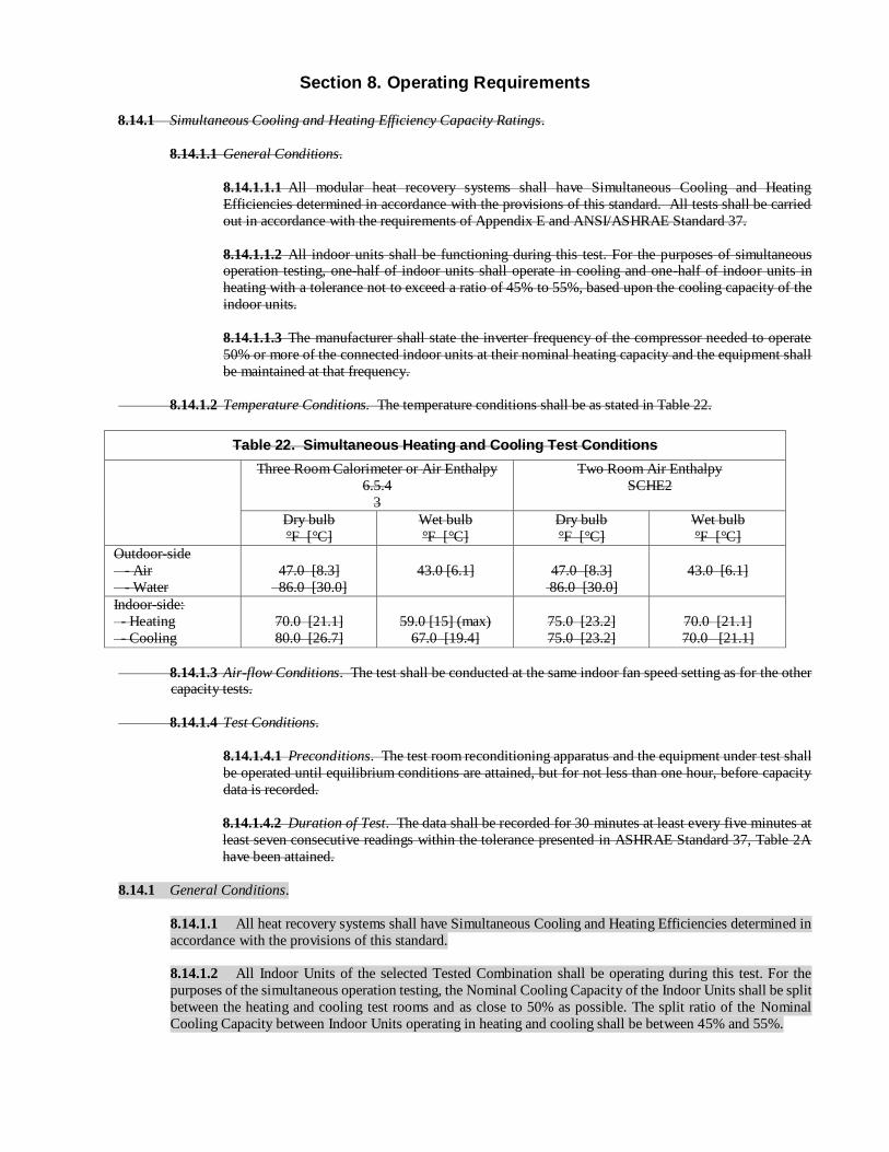
Section 8. Operating Requirements
8.14.1 Simultaneous Cooling and Heating Efficiency Capacity Ratings.
8.14.1.1 General Conditions.
8.14.1.1.1 All modular heat recovery systems shall have Simultaneous Cooling and Heating
Efficiencies determined in accordance with the provisions of this standard. All tests shall be carried
out in accordance with the requirements of Appendix E and ANSI/ASHRAE Standard 37.
8.14.1.1.2 All indoor units shall be functioning during this test. For the purposes of simultaneous operation testing, one-half of indoor units shall operate in cooling and one-half of indoor units in
heating with a tolerance not to exceed a ratio of 45% to 55%, based upon the cooling capacity of the
indoor units.
8.14.1.1.3 The manufacturer shall state the inverter frequency of the compressor needed to operate
50% or more of the connected indoor units at their nominal heating capacity and the equipment shall
be maintained at that frequency.
8.14.1.2 Temperature Conditions. The temperature conditions shall be as stated in Table 22.
Table 22. Simultaneous Heating and Cooling Test Conditions
Three Room Calorimeter or Air Enthalpy
6.5.4
3
Two Room Air Enthalpy
SCHE2
Dry bulb
°F [°C]
Wet bulb
°F [°C]
Dry bulb
°F [°C]
Wet bulb
°F [°C]
Outdoor-side
- Air
- Water
47.0 [8.3]
86.0 [30.0]
43.0 [6.1]
47.0 [8.3]
86.0 [30.0]
43.0 [6.1]
Indoor-side:
- Heating
- Cooling
70.0 [21.1]
80.0 [26.7]
59.0 [15] (max)
67.0 [19.4]
75.0 [23.2]
75.0 [23.2]
70.0 [21.1]
70.0 [21.1]
8.14.1.3 Air-flow Conditions. The test shall be conducted at the same indoor fan speed setting as for the other capacity tests.
8.14.1.4 Test Conditions.
8.14.1.4.1 Preconditions. The test room reconditioning apparatus and the equipment under test shall
be operated until equilibrium conditions are attained, but for not less than one hour, before capacity
data is recorded.
8.14.1.4.2 Duration of Test. The data shall be recorded for 30 minutes at least every five minutes at
least seven consecutive readings within the tolerance presented in ASHRAE Standard 37, Table 2A
have been attained.
8.14.1 General Conditions.
8.14.1.1 All heat recovery systems shall have Simultaneous Cooling and Heating Efficiencies determined in
accordance with the provisions of this standard.
8.14.1.2 All Indoor Units of the selected Tested Combination shall be operating during this test. For the
purposes of the simultaneous operation testing, the Nominal Cooling Capacity of the Indoor Units shall be split
between the heating and cooling test rooms and as close to 50% as possible. The split ratio of the Nominal
Cooling Capacity between Indoor Units operating in heating and cooling shall be between 45% and 55%.
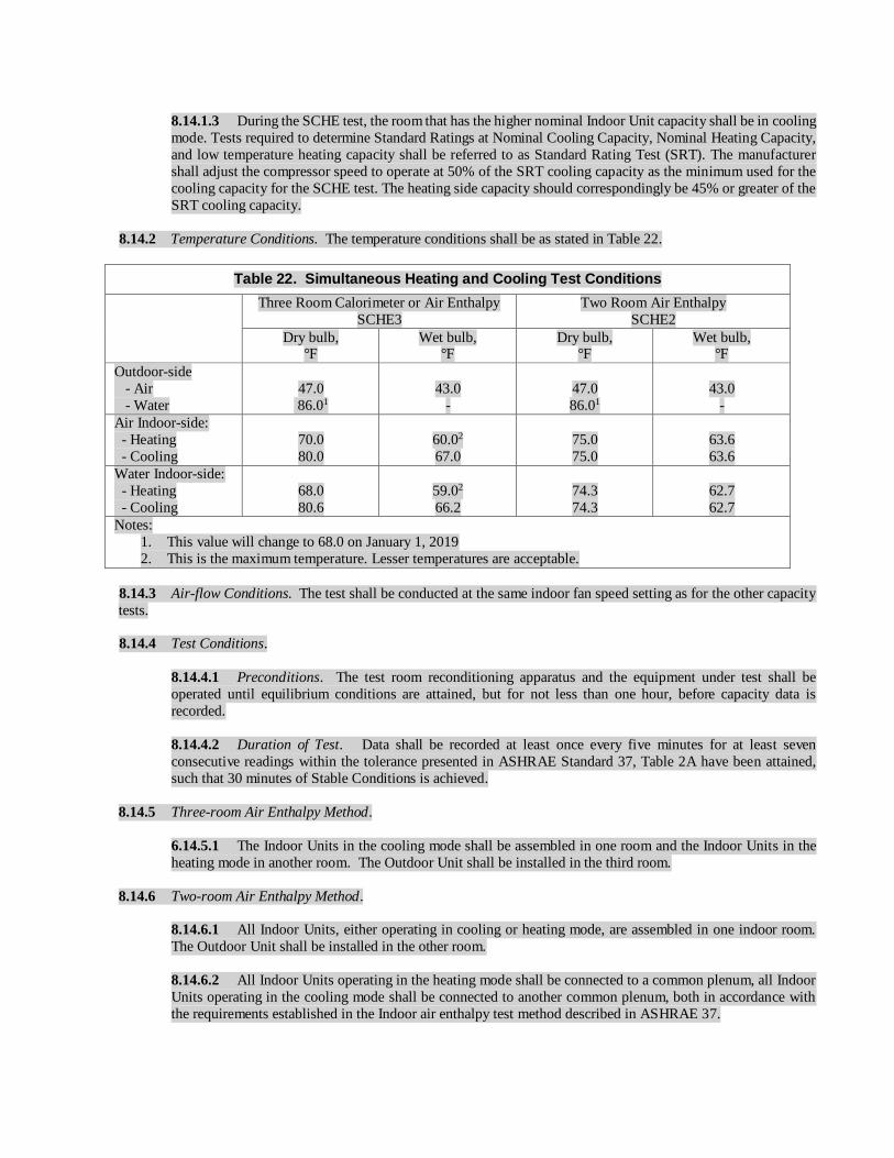
8.14.1.3 During the SCHE test, the room that has the higher nominal Indoor Unit capacity shall be in cooling
mode. Tests required to determine Standard Ratings at Nominal Cooling Capacity, Nominal Heating Capacity,
and low temperature heating capacity shall be referred to as Standard Rating Test (SRT). The manufacturer
shall adjust the compressor speed to operate at 50% of the SRT cooling capacity as the minimum used for the
cooling capacity for the SCHE test. The heating side capacity should correspondingly be 45% or greater of the
SRT cooling capacity.
8.14.2 Temperature Conditions. The temperature conditions shall be as stated in Table 22.
Table 22. Simultaneous Heating and Cooling Test Conditions
Three Room Calorimeter or Air Enthalpy
SCHE3
Two Room Air Enthalpy
SCHE2
Dry bulb, °F
Wet bulb, °F
Dry bulb, °F
Wet bulb, °F
Outdoor-side
- Air
- Water
47.0
86.01
43.0
-
47.0
86.01
43.0
-
Air Indoor-side:
- Heating
- Cooling
70.0
80.0
60.02
67.0
75.0
75.0
63.6
63.6
Water Indoor-side:
- Heating
- Cooling
68.0
80.6
59.02
66.2
74.3
74.3
62.7
62.7
Notes:
1. This value will change to 68.0 on January 1, 2019
2. This is the maximum temperature. Lesser temperatures are acceptable.
8.14.3 Air-flow Conditions. The test shall be conducted at the same indoor fan speed setting as for the other capacity
tests.
8.14.4 Test Conditions.
8.14.4.1 Preconditions. The test room reconditioning apparatus and the equipment under test shall be
operated until equilibrium conditions are attained, but for not less than one hour, before capacity data is
recorded.
8.14.4.2 Duration of Test. Data shall be recorded at least once every five minutes for at least seven
consecutive readings within the tolerance presented in ASHRAE Standard 37, Table 2A have been attained,
such that 30 minutes of Stable Conditions is achieved.
8.14.5 Three-room Air Enthalpy Method.
6.14.5.1 The Indoor Units in the cooling mode shall be assembled in one room and the Indoor Units in the
heating mode in another room. The Outdoor Unit shall be installed in the third room.
8.14.6 Two-room Air Enthalpy Method.
8.14.6.1 All Indoor Units, either operating in cooling or heating mode, are assembled in one indoor room.
The Outdoor Unit shall be installed in the other room.
8.14.6.2 All Indoor Units operating in the heating mode shall be connected to a common plenum, all Indoor
Units operating in the cooling mode shall be connected to another common plenum, both in accordance with
the requirements established in the Indoor air enthalpy test method described in ASHRAE 37.

APPENDIX C. UNIFORM TEST METHOD FOR MEASURING THE ENERGY CONSUMPTION OF CENTRAL AIR
CONDITIONERS AND HEAT PUMPS – NORMATIVE
C1 U.S. Department of Energy (DOE) Appendix M to Subpart B of 10 CFR Part 430 - Uniform Test
Method for Measuring the Energy Consumption of Central Air Conditioners and Heat Pumps.
Foreword: This appendix to ARI Standard 1230-2008 is the “Uniform Test Method for Measuring the Energy
Consumption of Central Air Conditioners and Heat Pumps” Appendix M to Subpart B of Part 430, pages 59135 through
59180, Federal Register, Vol. 70, No. 195, Tuesday, October 11, 2005 as amended by the Federal Register, Vol. 72, No.
203, Monday, October 22, 2007 pages 59906 through 59934.
APPENDIX M to Subpart B of Part 430 – Uniform Test Method for Measuring the Energy Consumption of Central
Air Conditioners and Heat Pumps
APPENDIX I. UNIT CONFIGURATION FOR STANDARD EFFICIENCY DETERMINATION FOR CAPACITY ABOVE
65,000 BTU/H - INFORMATIVE
I1 Purpose. This appendix is to be used in conjunction with the Tested Combination definition in the standard to
prescribe the requirements for the configuration of a system that is used for determining the Cooling and Heating Capacity at
Standard Rating Conditions and efficiency metrics at Standard Rating Conditions. This will allow for a uniform approach to
determine minimum and other Standard Rating metrics. This appendix is provided for the convenience of users. For official
requirements, refer to CFR 431 and DOE’s Enforcement Policy Statement: Commercial HVAC Equipment issued January
30, 2015 (http://energy.gov/gc/downloads/commercial-equipment-testing-enforcement-policies).
I2 Background. The Standard Ratings are intended to be ratings that define the performance of a basic model at a defined
set of Rating Conditions. The ratings include the following at Standard Rating Conditions:
I2.1 Standard cooling capacity
I2.2 Standard EER I2.3 IEER
I2.4 High temperature Heating Capacity
I2.5 High temperature COPH
I2.6 Low temperature Heating Capacity
I2.7 Low temperature COPH
I2.8 Simultaneous Cooling and Heating Efficiency, SCHE
VRF systems are complex systems designed to operate in a building HVAC system and often for non-standard Rating
Conditions and applications. This can include capabilities for enhanced dehumidification capabilities due to local weather
conditions and other system related features. This can include system features for overall annual efficiency improvement like
economizers, energy recovery, evaporative cooling, ventilation air requirements, and enhanced IAQ features and filtration.
Many of these features are addressed in building efficiency standards where they compensate for features such as economizers,
energy recovery, fan power, and indoor air quality (IAQ) features.
I3 Configuration Requirements.
I3.1 IAQ Features and Filtration.

I3.1.1 Standard Ratings shall be determined and tested with manufacturer standard, lowest level of air
filtration. For units with no filters, static pressure allowance of 0.08 in H2O shall be added to the minimum
static pressure shown in Table 9. If higher filtration is offered then the unit shall be tested without filters, at an
additional 0.08 in H2O external static pressure.
I3.1.2 UV Lights. A lighting fixture and lamp mounted so that it shines light on the indoor coil, that emits
ultraviolet light to inhibit growth of organisms on the indoor coil surfaces, the condensate drip pan, and/other
locations within the equipment. UV lights do not need to be turned on during test.
I3.2 System Features Excluded from Testing. VRF equipment can have many features that enhance the operation of
the unit on an annualized basis. Standards like ASHRAE Standard 90.1 include performance allowances and prescriptive
requirements for many of these features. Standard Ratings shall be determined and tested without the following features
if the manufacturer distributes in commerce an otherwise identical unit that does not have that feature.
I3.2.1 Economizers. An automatic system that enables a cooling system to supply and use outdoor air to
reduce or eliminate the need for mechanical cooling during mild or cold weather. They provide significant
energy efficiency improvements on an annualized basis, but are also a function of regional ambient conditions
and are not considered in the EER or IEER metric.
I3.2.2 Desiccant Dehumidification Components. An assembly that reduces the moisture content of the
Supply Air through moisture transfer with solid or liquid desiccants.
I3.2.3 Steam/Hydronic Heat Coils. Coils used instead of electric coils to provide primary or supplemental
heating.
I3.2.4 Coated Coils. An indoor coil or outdoor coil whose entire surface, including the entire surface of both fins and tubes, is covered with a thin continuous non-porous coating to reduce corrosion. A coating for
this purpose will be defined based on what is deemed to pass ANSI/ASTM B117 or ANSI/ASTM G85 test of
500 hours or more.
I3.3 Customer System Features.
I3.3.1 Hail Guards. A grille or similar structure mounted to the outside of the unit covering the outdoor
coil to protect the coil from hail, flying debris and damage from large objects. Hail guards shall be removed
during testing, if present.
I3.3.2 Snow/Wind Guards. A baffle and or ducting mounted to the air intake and discharge of the Outdoor
Unit.. Snow/Wind guards shall be removed during testing, if present.
I3.3.3 Grille Options. Various grille options can be used for airflow direction or customer preference.
Equipment should be tested with standard grilles.
I3.4 Dampers. Standard Ratings shall be determined and tested without the following dampers. If the sample has outdoor air or exhaust air dampers while testing, they shall be fully sealed to prevent operation.
I3.4.1 Fresh Air Dampers. An assembly with dampers and means to set the damper position in a closed
and one open position to allow air to be drawn into the equipment when the indoor fan is operating. For the
Standard Ratings, fresh air dampers shall be fully sealed.
I3.4.2 Low Ambient Cooling Dampers. An assembly with dampers and means to set the dampers in a
position to recirculate the warmer condenser discharge air to allow for reliable operation at low outdoor ambient
conditions. Low ambient cooling dampers shall be removed for testing.

APPENDIX J. DEVELOPMENT OF SUPPLEMENTAL TESTING INSTRUCTIONS FOR SET-UP AND TESTING OF
VRF MULTI-SPLIT SYSTEMS - INFORMATIVE
J1 Purpose. The purpose of this appendix is to provide guidance for manufacturers to develop the supplemental testing
instructions to better detail the manufacturer’s requirements for a proper installation of the VRF system in the testing laboratory.
This will allow for a uniform approach to determine minimum and other Standard Rating metrics. For official requirements,
refer to 10 CFR 429 and 431. This appendix applies to all air-source and all water-source VRF multi-split systems.
Note: The intent of the supplemental testing instructions PDF is to describe the layout of a system set-up in the laboratory. In
the event of conflicting Instructions regarding the set-up of the system, outdoor unit installation instructions prevail, followed
by the outdoor unit label, followed by the Indoor Unit installation instructions, followed by the supplemental PDF testing
instructions.
J2 Background. Manufacturers are required to certify ratings to the Department of Energy. In 10 CFR 429.43 Commercial
heating, ventilating, air conditioning (HVAC) equipment) it is stated:
“(4) Pursuant to § 429.12(b)(13 a certification report must include supplemental information submitted in PDF format. The
equipment-specific, supplemental information must include any additional testing and testing set up instructions
(e.g., charging instructions) for the basic model; identification of all special features that were included in rating the basic
model; and all other information (e.g., operational codes or component settings) necessary to operate the basic model under the required conditions specified by the relevant test procedure. A manufacturer may also include with a certification report
other supplementary items in PDF format (e.g., manuals) for DOE consideration in performing testing under subpart C of this
part. The equipment-specific, supplemental information must include at least the following:
(v) Variable refrigerant flow multi-split air conditioners with cooling capacity less than 65,000 Btu/h (3-phase): The
Nominal Cooling Capacity in British thermal units per hour (Btu/h); outdoor unit(s) and indoor units identified in the tested
combination; components needed for heat recovery, if applicable; rated airflow in standard cubic feet per minute (scfm) for
each indoor unit; water flow rate in gallons per minute (gpm) for water-source units only; rated static pressure in inches of
water; compressor frequency set points; required dip switch/control settings for step or variable components; a statement
whether the model will operate at test conditions without manufacturer programming; any additional testing instructions, if
applicable; if a variety of motors/drive kits are offered for sale as options in the basic model to account for varying installation
requirements, the model number and specifications of the motor (to include efficiency, horsepower, open/closed, and number
of poles) and the drive kit, including settings, associated with that specific motor that were used to determine the certified
rating; and which, if any, special features were included in rating the basic model. Additionally, upon DOE request, the
manufacturer must provide a layout of the system set-up for testing including charging instructions consistent with the
installation manual.
(vi) Variable refrigerant flow multi-split heat pumps with cooling capacity less than 65,000 Btu/h (3-phase): The Nominal
Cooling Capacity in British thermal units per hour (Btu/h); rated heating capacity in British thermal units per hour (Btu/h);
outdoor unit(s) and indoor units identified in the tested combination; components needed for heat recovery, if applicable; rated
airflow in standard cubic feet per minute (scfm) for each indoor unit; water flow rate in gallons per minute (gpm) for water-
source units only; rated static pressure in inches of water; compressor frequency set points; required dip switch/control settings
for step or variable components; a statement whether the model will operate at test conditions without manufacturer
programming; any additional testing instructions, if applicable; if a variety of motors/drive kits are offered for sale as options
in the basic model to account for varying installation requirements, the model number and specifications of the motor (to
include efficiency, horsepower, open/closed, and number of poles) and the drive kit, including settings, associated with that
specific motor that were used to determine the certified rating; and which, if any, special features were included in rating the
basic model. Additionally, upon DOE request, the manufacturer must provide a layout of the system set-up for testing including
charging instructions consistent with the installation manual.
(vii) Variable refrigerant flow multi-split air conditioners with cooling capacity greater than or equal to 65,000 Btu/h:
The Nominal Cooling Capacity in British thermal units per hour (Btu/h); outdoor unit(s) and indoor units identified in the tested combination; components needed for heat recovery, if applicable; rated airflow in standard cubic feet per minute (scfm) for
each indoor unit; water flow rate in gallons per minute (gpm) for water-source units only; rated static pressure in inches of
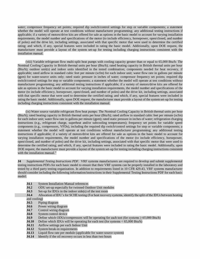
water; compressor frequency set points; required dip switch/control settings for step or variable components; a statement
whether the model will operate at test conditions without manufacturer programming; any additional testing instructions if
applicable; if a variety of motors/drive kits are offered for sale as options in the basic model to account for varying installation
requirements, the model number and specifications of the motor (to include efficiency, horsepower, open/closed, and number
of poles) and the drive kit, including settings, associated with that specific motor that were used to determine the certified
rating; and which, if any, special features were included in rating the basic model. Additionally, upon DOE request, the
manufacturer must provide a layout of the system set-up for testing including charging instructions consistent with the
installation manual.
(viii) Variable refrigerant flow multi-split heat pumps with cooling capacity greater than or equal to 65,000 Btu/h: The
Nominal Cooling Capacity in British thermal units per hour (Btu/h); rated heating capacity in British thermal units per hour
(Btu/h); outdoor unit(s) and indoor units identified in the tested combination; components needed for heat recovery, if
applicable; rated airflow in standard cubic feet per minute (scfm) for each indoor unit; water flow rate in gallons per minute
(gpm) for water-source units only; rated static pressure in inches of water; compressor frequency set points; required dip
switch/control settings for step or variable components; a statement whether the model will operate at test conditions without
manufacturer programming; any additional testing instructions if applicable; if a variety of motors/drive kits are offered for
sale as options in the basic model to account for varying installation requirements, the model number and specifications of the
motor (to include efficiency, horsepower, open/closed, and number of poles) and the drive kit, including settings, associated
with that specific motor that were used to determine the certified rating; and which, if any, special features were included in
rating the basic model. Additionally, upon DOE request, the manufacturer must provide a layout of the system set-up for testing
including charging instructions consistent with the installation manual.
(ix) Water source variable refrigerant flow heat pumps: The Nominal Cooling Capacity in British thermal units per hour
(Btu/h); rated heating capacity in British thermal units per hour (Btu/h); rated airflow in standard cubic feet per minute (scfm) for each indoor unit; water flow rate in gallons per minute (gpm); rated static pressure in inches of water; refrigeration charging
instructions (e.g., refrigerant charge, superheat and/or subcooling temperatures); frequency set points for variable speed
components (e.g., compressors, VFDs), including the required dip switch/control settings for step or variable components; a
statement whether the model will operate at test conditions without manufacturer programming; any additional testing
instructions if applicable; if a variety of motors/drive kits are offered for sale as options in the basic model to account for
varying installation requirements, the model number and specifications of the motor (to include efficiency, horsepower,
open/closed, and number of poles) and the drive kit, including settings, associated with that specific motor that were used to
determine the certified rating; and which, if any, special features were included in rating the basic model. Additionally, upon
DOE request, the manufacturer must provide a layout of the system set-up for testing including charging instructions consistent
with the installation manual.”
J4 Supplemental Testing Instructions PDF. VRF systems manufacturers are required to develop and submit supplemental
testing instructions PDFs for each basic model to ensure that their VRF systems can be properly installed in the laboratory and
tested by a third party testing organization. In addition to requirements listed in 10 CFR 429.43, VRF systems manufacturer
should consider including the following information/instructions in their Supplemental Testing Instructions PDF for each basic
model:
J4.1 System Installation Manual references
J4.2 ODU set-up especially for twinned Outdoor Unit modules
J4.3 Set-up for IDUs in the indoor side(s) of the test room
J4.4 Allocation of IDU’s for SCHE testing (For heat recovery systems, identify the split of the IDUs between heating
and cooling)
J4.5 Piping diagram
J4.6 Power wiring diagram
J4.7 Control wiring diagram
J4.8 System control device
J4.9 Define which ODUs/compressors will be operating for each test (for systems ≥ 65,000 Btu/h)
J4.10 Define which IDUs will be operating for each test (for systems < 65,000 Btu/h)
J4.11 Airflow settings per each Indoor Unit
J4.12 System break-in requirements
J4.13 Liquid flow rate per module (applicable for water-source system)
J4.14 Identify if the oil recovery occurs in less than two hours

J5 Examples of System Layout Figures.
Figure J1. Typical Wiring Diagram for Heat Pump
Figure J2. Typical Wiring Diagram for Heat Recovery
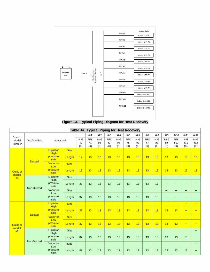
Figure J3. Typical Piping Diagram for Heat Recovery
Table J4. Typical Piping for Heat Recovery
System Model
Number Duct/Nonduct Indoor Unit
#1 #2 #3 #4 #5 #6 #7 #8 #9 #10 #11 #12
PIPE A
(ft)
PIPE #1 (ft)
PIPE #2 (ft)
PIPE #3 (ft)
PIPE #4 (ft)
PIPE #5 (ft)
PIPE #6 (ft)
PIPE #7 (ft)
PIPE #8 (ft)
PIPE #9 (ft)
PIPE #10 (ft)
PIPE #11 (ft)
PIPE #12 (ft)
Outdoor
model #1
Ducted
Liquid or High
pressure side
Size
Length 12 13 13 13 13 13 13 13 13 13 13 13 13
Vapor or
Low
pressure side
Size
Length 12 13 13 13 13 13 13 13 13 13 13 13 13
Non-Ducted
Liquid or
High pressure
side
Size - - - -
Length 37 13 13 13 13 13 13 13 13 - - - -
Vapor or
Low pressure
side
Size - - - -
Length 37 13 13 13 13 13 13 13 13 - - - -
Outdoor
model #2
Ducted
Liquid or High
pressure side
Size - -
Length 37 13 13 13 13 13 13 13 13 13 13 - -
Vapor or Low
pressure side
Size - -
Length 37 13 13 13 13 13 13 13 13 13 13 - -
Non-Ducted
Liquid or
High pressure
side
Size -
Length 87 13 13 13 13 13 13 13 13 13 13 13 -
Vapor or
Low pressure
side
Size -
Length 87 13 13 13 13 13 13 13 13 13 13 13 -
Hea
t R
eco
ver
y
Ref
rig
eran
t D
istr
ibu
tor

AHRI CERTIFICATION PROGRAM PROVISIONS
Scope of the Certification Program
The Certification Program includes all Variable Refrigerant Flow (VRF) Multi-Split Air-Conditioning,Heat Pump, and Heat
Recovery Equipment rated at AHRI Standard Rating Conditions.
Certified Ratings
The following Certification Program ratings are verified by test:
Variable Refrigerant Flow (VRF) Multi-Split Air-Conditioning and Heat Pump Equipment
a. For VRF Multi-Split Air-Conditioners < 65,000 Btu/h [19,000 W]
1. Standard Rating Cooling Capacity, Btu/h [W]
2. Seasonal Energy Efficiency Ratio, SEER, Btu/(Wh)
3. Energy Efficiency Ratio, EER, Btu/(Wh)
b. For VRF Multi-Split Air-Conditioners ≥ 65,000 Btu/h [19,000 W]
1. Standard Rating Cooling Capacity, Btu/h [W]
2. Energy Efficiency Ratio, EER, Btu/(Wh) 3. Integrated Energy Efficiency Ratio, IEER
c. For VRF Multi-Split Heat Pumps < 65,000 Btu/h [19,000 W]
1. Standard Rating Cooling Capacity, Btu/h [W]
2. Seasonal Energy Efficiency Ratio, SEER, Btu/(Wh)
3. Energy Efficiency Ratio, EER, Btu/(Wh) 4. High Temperature Heating Standard Rating Capacity, Btu/h [W]
5. Region IV Heating Seasonal Performance Factor, HSPF, Minimum Design Heating Requirement, Btu/(Wh)
d. For VRF Multi-Split Heat Pumps ≥ 65,000 Btu/h [19,000 W]
1. Standard Rating Cooling Capacity, Btu/h [W]
2. Energy Efficiency Ratio, EER, Btu/(Wh) 3. Integrated Energy Efficiency Ratio
4. High Temperature Heating Standard Rating Capacity, Btu/h [W]
5. High Temperature Coefficient of Performance, COP
IMPORTANT
SAFETY DISCLAIMER AHRI does not set safety standards and does not certify or guarantee the safety of any products, components or
systems designed, tested, rated, installed or operated in accordance with this standard/guideline. It is strongly recommended that products be designed, constructed, assembled, installed and operated in accordance with
nationally recognized safety standards and code requirements appropriate for products covered by this
standard/guideline.
AHRI uses its best efforts to develop standards/guidelines employing state-of-the-art and accepted industry
practices. AHRI does not certify or guarantee that any tests conducted under its standards/guidelines will be non-
hazardous or free from risk.

Price $10.00 (M) $20.00 (NM) © Copyright 2017, by Air-Conditioning, Heating, and Refrigeration Institute
Printed in U.S.A. Registered United States Patent and Trademark Office
6. Low Temperature Heating Standard Rating Capacity, Btu/h [W]
7. Low Temperature Coefficient of Performance, COP
e. For VRF Multi-Split Heat Recovery Heat Pumps
1. Ratings Appropriate in (c) and (d) above
2. Simultaneous Cooling and Heating Efficiency (SCHE) (50% heating/50% cooling).
f. For VRF Multi-Split Heat Pump Systems that Use a Water Source for Heat Rejection 1. Standard Rating Cooling Capacity, Btu/h [W]
2. Energy Efficiency Ratio, EER, Btu/(Wh) 3. Integrated Energy Efficiency Ratio, IEER
4. Heating Standard Rating Capacity, Btu/h [W]
5. Heating Coefficient of Performance, COP
6. Simultaneous Cooling and Heating Efficiency (SCHE) (50% heating/50% cooling)(Heat Recovery models
only)
Conformance to the requirements of the Maximum Operating Conditions Test, Voltage Tolerance Test, Low-Temperature
Operation Test (Cooling), Insulation Effectiveness Test (Cooling), and Condensate Disposal Test (Cooling), as outlined in
Section 8, are also verified by test.
Note:
This standard supersedes ANSI/AHRI Standard 1230-2010 with Addenda 1 and 2.

TABLE OF CONTENTS
SECTION PAGE
Section 1. Purpose .................................................................................................................................. 1
Section 2. Scope...................................................................................................................................... 1
Section 3. Definitions ............................................................................................................................. 1
Section 4. Classifications ....................................................................................................................... 8
Section 5. Test Requirements ................................................................................................................ 9
Section 6. Rating Requirements .......................................................................................................... 10
Section 7. Minimum Data Requirements for Published Ratings ....................................................... 36
Section 8. Operating Requirements ..................................................................................................... 37
Section 9. Marking and Nameplate Data ............................................................................................ 48
Section 10. Conformance Conditions .................................................................................................... 48
TABLES
TABLE PAGE
Table 1 Nominal Cooling Capacity Buckets .................................................................................... 7
Table 2 Classification of VRF Multi-Split Systems ......................................................................... 8
Table 3 Values of Standard Capacity Ratings ................................................................................ 11
Table 4 Piping Requirements for Tested Combinations Installation ............................................ 17
Table 5 Refrigerant Line Length Correction Factors ..................................................................... 18
Table 6 Cooling Mode Test Conditions for Units < 65,000 Btu/h [19,000 W] ........................... 19
Table 7 Heating Mode Test Conditions for Units < 65,000 Btu/h [19,000 W] ............................ 20
Table 8 Conditions for Operating Requirement Tests for Air-cooled Equipment
< 65,000 Btu/h [19,000 W] ................................................................................................ 21
Table 9 Minimum External Static Pressure for Ducted Systems Tested with External
Static Pressure > 0 [in H20] ............................................................................................... 21
Table 10 Operating Conditions for Standard Rating and Performance Operating Tests
for Systems ≥ 65,000 Btu/h [19,000W]............................................................................. 24
Table 11 Test Conditions for the Determination of Cooling Capacity for Systems that
Use a Water Source for Heat Rejection ............................................................................. 27
Table 12 Test Conditions for the Determination of Heating Capacity for Systems that
Use a Water Source for Heat Rejection ............................................................................. 28
Table 12 IEER Part-Load Rating Conditions ................................................................................... 23
Table 13 Uncertainty Allowances ..................................................................................................... 36
Table 14 Maximum Cooling Test Conditions for Systems that Use a Water Source for
Heat Rejection ..................................................................................................................... 42
Table 15 Maximum Heating Test Conditions for Systems that Use a Water Source for
Heat Rejection ..................................................................................................................... 42
Table 16 Minimum Cooling Test Conditions for Systems that Use a Water Source for
Heat Rejection ..................................................................................................................... 43
Table 17 Minimum Heating Test Conditions for Systems that Use a Water Source for
Heat Rejection ..................................................................................................................... 43
Table 18 Enclosure Sweat and Condensate Test Conditions for Systems that Use a
Water Source for Heat Rejection ....................................................................................... 44
Table 19 Uncertainties of Measurement for Indicated Values ........................................................ 44
Table 20 Variations Allowed in Capacity Test Readings ................................................................ 45
Table 21 Variations Allowed in Performance Test Readings.......................................................... 45
Table 22 Simultaneous Heating and Cooling Test Conditions ........................................................ 46
LIST OF FIGURES
FIGURE PAGE
Figure 1 Test Room Layout .............................................................................................................. 17
Figure 2 Example Revised Part Load Ambient Conditions for Interpolation ................................ 34

APPENDICES
APPENDIX PAGE
Appendix A References – Normative ..................................................................................................... 49
Appendix B References – Informative ................................................................................................... 49
Appendix C Uniform Test Method for Measuring the Energy Consumption of Central Air
Conditioners and Heat Pumps – Normative ...................................................................... 50
Appendix M to Subpart B of Part 430 – Uniform Test Method for Measuring the
Energy Consumption of Central Air Conditioners and Heat Pumps ............................... 41
Appendix D Test Requirements – Normative ........................................................................................ 50
Appendix E Heat Recovery Test Method – Normative......................................................................... 73
Appendix F Individual Indoor Unit Capacity Tests – Normative ........................................................ 85
Appendix G Prescriptive Methodology for the Cyclic Testing Of Ducted Systems – Normative ........ 93
Appendix H Integrated Part-load Values (IPLV) – Normative ............................................................. 98
Appendix I Unit Configuration for Standard Efficiency Determination for Capacity
Above 65,000 Btu/h – Informative .................................................................................. 102
Appendix J Development of Supplemental Testing Instructions for Set-up and Testing of VRF Multi-
split Systems – Informative ............................................................................................. 104
TABLES FOR APPENDICES
TABLE PAGE
Table D1 Sizes of Calorimeter ........................................................................................................... 56
Table D2 Variations Allowed During Steady State Cooling and Heating Capacity Tests
That Only Apply When Using the Indoor Air Enthalpy Method .................................... 62
Table D3 Variations Allowed During the Transient Heating Tests That Only Apply When
Using The Indoor Air Enthalpy Test Method ................................................................... 62
Table E1 Simultaneous Heating and Cooling Test Conditions ........................................................ 73
Table E2 Variations Allowed During Steady State Cooling And Heating Capacity
Tests That Only Apply When Using The Indoor Air Enthalpy Method ......................... 75
Table E3 Variations Allowed During The Transient Heating Tests That Only Apply
When Using The Indoor Air Enthalpy Test Method ........................................................ 75

Table E4 Data To Be Recorded During The Indoor Air-Enthalpy Capacity Tests ........................ 82
Table E5 Data To Be Recorded For Calorimeter Cooling Capacity Tests...................................... 82
Table E6 Data To Be Recorded For Calorimeter Heating Capacity Tests ...................................... 83
Table E7 Cooling Capacity Test Conditions ..................................................................................... 84
Table F1 Pressure Requirement for Comfort Air Conditioners ....................................................... 86
Table F2 Cooling Capacity Test Conditions ..................................................................................... 86
Table F3 Voltages for Capacity and Performance Tests .................................................................. 86
Table F4 Variations Allowed In Heating Capacity Tests When Using the
T Transient (“T”) Test Procedure ...................................................................................... 92
Table H1 Example IPLV Calculation (I-P UNITS) ........................................................................ 101
Table J1 Typical Piping for Heat Recovery ................................................................................... 107
FIGURES FOR APPENDICES
FIGURE PAGE
Figure D1 External Static Pressure Measurement .............................................................................. 51
Figure D2 External Static Pressure Measurements............................................................................. 52
Figure D3 Air Static Pressure Drop Measurement for a Coil-only Unit ........................................... 53
Figure D4 Setup for Wall Mounted Indoor Units ............................................................................... 55
Figure D5 Typical Calibrated Room-type Calorimeter ...................................................................... 57
Figure D6 Typical Balanced Ambient Room-type Calorimeter ........................................................ 58
Figure D7 Calorimeter Energy Flows During Cooling Capacity Tests ............................................ 59
Figure D8 Calorimeter Energy Flows During Heating Capacity Tests ............................................. 61
Figure D9 Discharge Chamber Requirements When Using the Indoor
Air Enthalpy Test Method for Non-ducted Unit ............................................................... 63
Figure D10 Tunnel Air-enthalpy Method.............................................................................................. 65
Figure D11 Loop Air-enthalpy Test Method Arrangement ................................................................. 66

Figure D12 Calorimeter Air-enthalpy Test Method Arrangement ...................................................... 67
Figure D13 Airflow Measuring Apparatus ........................................................................................... 68
Figure D14 Airflow Measuring Nozzle ................................................................................................. 71
Figure D15 Pressure-equalizing Device ................................................................................................ 72
Figure E1 Discharge Chamber Requirements When Using the Indoor
Air Enthalpy Test Method for Non Ducted Unit .............................................................. 75
Figure E2 Tunnel Air Enthalpy Method ............................................................................................. 77
Figure E3 Loop Air-enthalpy Test Method Arrangement ................................................................. 78
Figure E4 Calorimeter Air-enthalpy Test Method Arrangement ...................................................... 79
Figure F1 Flowchart of Selecting ESP for Rating Ducted Indoor Units .......................................... 88
Figure G1 Tunnel Air Enthalpy Test Method Arrangement .............................................................. 94
Figure G2 Loop Air Enthalpy Test Method Arrangement ................................................................. 95
Figure G3 Calorimeter Air Enthalpy Test Method Arrangement ...................................................... 96
Figure G4 Room Air Enthalpy Test Method Arrangement................................................................ 97
Figure H1 Part-load Factor Example ................................................................................................. 100
Figure J1 Typical Wiring Diagram for Heat Pump ........................................................................ 106
Figure J2 Typical Wiring Diagram for Heat Recovery .................................................................. 106
Figure J3 .......... Typical Piping Diagram for Heat Recovery .................................................................... 107

______________________________________________ AHRI STANDARD 1230-2014-WITH ADDENDUM 1
1
PERFORMANCE RATING OF VARIABLE REFRIGERANT FLOW (VRF) MULTI-SPLIT AIR-CONDITIONING AND HEAT
PUMP EQUIPMENT
Section 1. Purpose
1.1 Purpose. The purpose of this standard is to establish for Variable Refrigerant Flow (VRF) Multi-Split Air Conditioners
and Heat Pumps: definitions; classifications; test requirements; rating requirements; minimum data requirements for Published
Ratings; operating requirements; marking and nameplate data; and conformance conditions.
1.1.1 Intent. This standard is intended for the guidance of the industry, including manufacturers, engineers, installers, contractors and users.
1.1.2 Review and Amendment. This standard is subject to review and amendment as technology advances.
Section 2. Scope
2.1 This standard covers matched variable refrigerant flow Multi-Split Air Conditioners and Multi-Split Heat Pumps using
distributed refrigerant technology as defined in Section 3.
2.2 This standard applies to variable refrigerant flow multi-split systems consisting of the following matched components:
a) an outdoor unit with single or multiple compressors or variable capacity compressor or with a variable speed drive; b) indoor
unit(s) that have a coil, air movement device intended for single zone air distribution, and a temperature sensing control; and
c) a zone temperature control device.
2.3 The multi-split systems covered in this standard are Variable Refrigerant Flow (VRF) Multi-Split Systems and Heat
Recovery (VRF) Multi-Split Systems. Included are multi-split, matched system air conditioners and Heat Pumps irrespective of their type of electric power source, type of refrigeration cycle, or secondary fluid (e.g. air-to-air or water-to-air).
2.4 This standard does not apply to the testing and rating of individual assemblies for separate use. It also does not cover
ductless mini-splits (one-to-one split systems) which are covered by AHRI Standard 210/240.
2.5 Energy Source. This standard applies only to electrically operated, vapor compression refrigeration systems.
Note: For the purpose of the remaining clauses, the terms equipment and systems will be used to mean multi-split air-
conditioners and/or multi-split Heat Pumps that are described in Sections 2.1 to 2.5.
Section 3. Definitions
All terms in this document shall follow the standard industry definitions established in the current edition of ASHRAE
Terminology of Heating, Ventilation, Air Conditioning and Refrigeration, unless otherwise defined in this section.
All terms in this document will follow the standard industry definitions in the ASHRAE Terminology website (https://www.ashrae.org/resources--publications/free-resources/ashrae-terminology) unless otherwise defined in this section.
For the purposes of this Standard, the following definitions apply:
3.1 Standard Air. Air weighing 0.075 lb/ft3 [1.2 kg/m3] which approximates dry air at 70F [21C] and at a barometric pressure of 29.92 in Hg [101.3 kPa].
3.1 Airflow Setting(s). Programmed or wired control system configurations that control a fan to achieve discrete, differing
ranges of airflow—often designated for performing a specific function (e.g., cooling, heating, or constant circulation)—without
manual adjustment other than interaction with a user-operable control (i.e., a thermostat) that meets the manufacturer
specifications for installed-use. For the purposes of this standard, manufacturer specifications for installed-use are those found
in the product literature shipped with the unit.

AHRI STANDARD 1230-2014-WITH ADDENDUM 1 ______________________________________________
2
3.2 Multi-Split Air-Conditioner. An encased, factory-made assembly or assemblies designed to be used as permanently
installed equipment to provide conditioned air to an enclosed space(s). It includes a prime source of refrigeration for cooling
and dehumidification and may optionally include other means for heating, humidifying, circulating and cleaning the air. It
normally includes multiple evaporator(s), compressor(s), and condenser(s). Such equipment may be provided in more than
one assembly, the separated assemblies of which are intended to be used together.
3.2 Capacity.
3.2.1 Full Capacity. The capacity of the system when all indoor units and outdoor units are operated in the same
mode, at their Rated Capacity in Btu/h [W].
3.2.2 Heating Capacity. The amount of heat the equipment can add to the conditioned space in a defined interval of
time in Btu/h [W].
3.2.3 Latent Cooling Capacity. Capacity associated with a change in humidity ratio.
3.2.4 Nominal Capacity. The capacity value of the outdoor units published by the manufacturer in their catalogue or
Engineering Data. Nominal Capacity may be referred to using the following terms:
3.2.4.1 Nominal Cooling Capacity. The Nominal Cooling Capacity shall not be more that 105% of the rated
cooling capacity. The Nominal Cooling Capacity of each Indoor Unit shall be the published capacity when the
ratings are first established, and shall not be changed upon subsequent publications.
3.2.4.2 Nominal Heating Capacity. Nominal Capacity in heating mode.
3.2.5 Sensible Cooling Capacity. The rate, expressed in Btu/h, at which the equipment lowers the dry-bulb
temperature (removes sensible heat) of the air passing through it under specified conditions of operation.
3.2.6 Total Cooling Capacity. The amount of sensible and latent heat the equipment can remove from the conditioned
space in a defined interval of time in Btu/h.
3.2.7 Rated Capacity. The capacity achieved at the Standard Rating Conditions in Btu/h.
3.3 Coefficient of Performance (COP). A ratio of the heating capacity in watts [W] to the power input values in watts [W]
at any given set of rating conditions expressed in watts/watts [W/W]. For heating COP, supplementary resistance heat shall be
excluded.
3.4 Degradation Coefficient (CD). The measure of the efficiency loss due to the on/off cycling of the complete system as
determined in Appendices C, D and G.
3.5 Ducted Systems. A multi-split air conditioner or heat pump system with only Indoor Units designed to be permanently installed and deliver all conditioned air through ductwork.
3.6 Effective Power Input (PE). Average electrical power input to the equipment expressed in watts [W] and obtained from:
a) Power input for operation of the compressor
b) Power input to electric heating devices used only for defrosting
c) Power input to all control and safety devices of the equipment
d) Power input to factory installed condensate pumps and
e) Power input for operation of all fans and, if applicable, any water-cooled condenser pump(s).
3.7 Energy Efficiency Ratio (EER). A ratio of the Total Cooling Capacity in Btu/h to the power input values in watts [W]
at any given set of rating conditions expressed in Btu/W·h.
3.8 Ground-Water Heat Pump. Water-to-air heat pump using water pumped from a well, lake, or stream functioning as a
heat source/heat sink. The temperature of the water is related to the climatic conditions and may vary from 41º to 77ºF [5° to 25°C] for deep wells.
3.9 Ground-Loop Heat Pump. Brine-to-air heat pump using a brine solution circulating through a subsurface piping loop
functioning as a heat source/heat sink. The heat exchange loop may be placed in horizontal trenches, vertical bores, or be
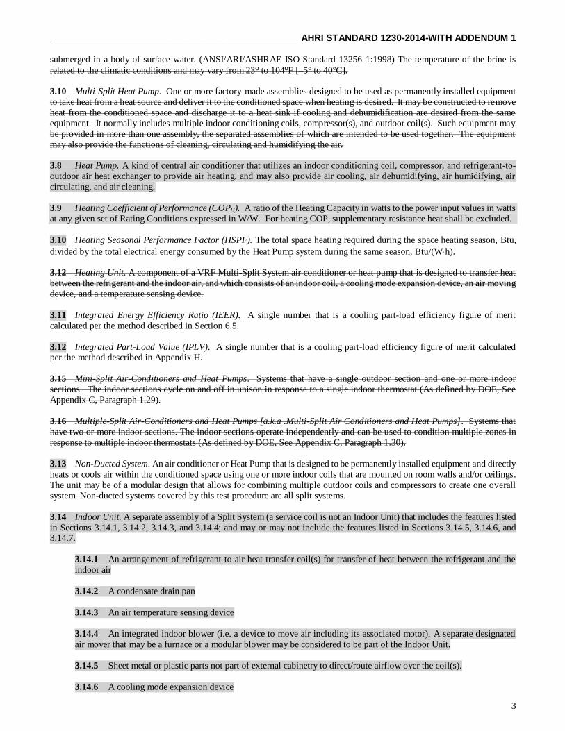
______________________________________________ AHRI STANDARD 1230-2014-WITH ADDENDUM 1
3
submerged in a body of surface water. (ANSI/ARI/ASHRAE ISO Standard 13256-1:1998) The temperature of the brine is
related to the climatic conditions and may vary from 23º to 104ºF [–5° to 40°C].
3.10 Multi-Split Heat Pump. One or more factory-made assemblies designed to be used as permanently installed equipment
to take heat from a heat source and deliver it to the conditioned space when heating is desired. It may be constructed to remove
heat from the conditioned space and discharge it to a heat sink if cooling and dehumidification are desired from the same
equipment. It normally includes multiple indoor conditioning coils, compressor(s), and outdoor coil(s). Such equipment may
be provided in more than one assembly, the separated assemblies of which are intended to be used together. The equipment
may also provide the functions of cleaning, circulating and humidifying the air.
3.8 Heat Pump. A kind of central air conditioner that utilizes an indoor conditioning coil, compressor, and refrigerant-to-
outdoor air heat exchanger to provide air heating, and may also provide air cooling, air dehumidifying, air humidifying, air
circulating, and air cleaning. 3.9 Heating Coefficient of Performance (COPH). A ratio of the Heating Capacity in watts to the power input values in watts
at any given set of Rating Conditions expressed in W/W. For heating COP, supplementary resistance heat shall be excluded.
3.10 Heating Seasonal Performance Factor (HSPF). The total space heating required during the space heating season, Btu,
divided by the total electrical energy consumed by the Heat Pump system during the same season, Btu/(Wh).
3.12 Heating Unit. A component of a VRF Multi-Split System air conditioner or heat pump that is designed to transfer heat
between the refrigerant and the indoor air, and which consists of an indoor coil, a cooling mode expansion device, an air moving
device, and a temperature sensing device.
3.11 Integrated Energy Efficiency Ratio (IEER). A single number that is a cooling part-load efficiency figure of merit
calculated per the method described in Section 6.5.
3.12 Integrated Part-Load Value (IPLV). A single number that is a cooling part-load efficiency figure of merit calculated per the method described in Appendix H.
3.15 Mini-Split Air-Conditioners and Heat Pumps. Systems that have a single outdoor section and one or more indoor
sections. The indoor sections cycle on and off in unison in response to a single indoor thermostat (As defined by DOE, See
Appendix C, Paragraph 1.29).
3.16 Multiple-Split Air-Conditioners and Heat Pumps [a.k.a .Multi-Split Air Conditioners and Heat Pumps]. Systems that
have two or more indoor sections. The indoor sections operate independently and can be used to condition multiple zones in
response to multiple indoor thermostats (As defined by DOE, See Appendix C, Paragraph 1.30).
3.13 Non-Ducted System. An air conditioner or Heat Pump that is designed to be permanently installed equipment and directly
heats or cools air within the conditioned space using one or more indoor coils that are mounted on room walls and/or ceilings.
The unit may be of a modular design that allows for combining multiple outdoor coils and compressors to create one overall
system. Non-ducted systems covered by this test procedure are all split systems.
3.14 Indoor Unit. A separate assembly of a Split System (a service coil is not an Indoor Unit) that includes the features listed
in Sections 3.14.1, 3.14.2, 3.14.3, and 3.14.4; and may or may not include the features listed in Sections 3.14.5, 3.14.6, and 3.14.7.
3.14.1 An arrangement of refrigerant-to-air heat transfer coil(s) for transfer of heat between the refrigerant and the
indoor air
3.14.2 A condensate drain pan
3.14.3 An air temperature sensing device
3.14.4 An integrated indoor blower (i.e. a device to move air including its associated motor). A separate designated
air mover that may be a furnace or a modular blower may be considered to be part of the Indoor Unit.
3.14.5 Sheet metal or plastic parts not part of external cabinetry to direct/route airflow over the coil(s).
3.14.6 A cooling mode expansion device

AHRI STANDARD 1230-2014-WITH ADDENDUM 1 ______________________________________________
4
3.14.7 External cabinetry
3.15 Indoor Unit Model Family. A model family constituting exclusively of the following types of Non-ducted Indoor Units.
3.15.1 Ceiling suspended. A non-ducted indoor unit that is totally encased and is suspended below the ceiling.
3.15.2 Floor-mounted. A non-ducted Indoor Unit intended for being installed at floor level either enclosed in the wall space in an uncased configuration or extended out from the wall in a cased configuration.
3.15.3 Wall-mounted. A non-ducted Indoor Unit that is attached to the wall with a cased configuration, sometimes
referred to as a high-wall unit.
3.15.4 Ceiling Cassettes. Non-ducted Indoor Units intended to be installed flush mounted with the ceiling. These
indoor units can have configurations of indoor airflow coming from one, two, four, or circular direction.
3.16 Non-ducted Indoor Unit. An Indoor Unit designed to be permanently installed, mounted on room walls, floors and/or
ceilings, which directly heats or cools air within the conditioned space. Non-ducted Indoor Units consists of the following
types: Wall-mounted, Floor-mounted, Ceiling Suspended, and Ceiling Cassette (standard and compact).
3.17 Oil Recovery Mode. An automatic system operation that returns oil to the compressor crank case when the control
system determines oil recovery is needed.
3.18 Outdoor Unit. A separate assembly of a Split System that transfers heat between the refrigerant and the outdoor air or refrigerant and water, and consists of an outdoor heat exchanger, compressor(s), an air moving device, and in addition for Heat
Pumps, may include a heating mode expansion device, reversing valve, and/or defrost controls; Water Source Heat Pumps may
not have an air movement device.
3.19 Outdoor Unit. A component of a split-system central air conditioner or heat pump that is designed to transfer heat between refrigerant and air, or refrigerant and water, and which consists of an outdoor coil, compressor(s), an air moving device,
and in addition for heat pumps, a heating mode expansion device, reversing valve, and defrost controls.
3.19 Published Rating. A statement of the assigned values of those performance characteristics, under stated rating
conditions, by which a unit may be chosen to fit its application. These values apply to all systems of like nominal size and type
produced by the same manufacturer. As used herein, the term Published Rating includes the rating of all performance
characteristics shown on the unit or published in specifications, advertising or other literature controlled by the manufacturer,
at stated Rating Conditions.
3.19.1 Application Rating. A rating based on tests performed at application Rating Conditions (other than Standard
Rating Conditions).
3.19.2 Standard Rating. A rating based on tests performed at Standard Rating Conditions.
3.20 Seasonal Energy Efficiency Ratio (SEER). The total cooling of a system covered by this standard with a capacity
<65,000 Btu/h [19,000 W] during its normal usage period for cooling (not to exceed 12 months) divided by the total electric
energy input during the same period as determined in Appendix C, expressed in Btu/[Wh].
3.21 “Shall” or “Should”. “Shall” or “should” shall be interpreted as follows:
3.21.1 Shall. Where “shall” or “shall not” is used for a provision specified, that provision is mandatory if compliance
with the standard is claimed.
3.21.2 Should. “Should” is used to indicate provisions which are not mandatory but which are desirable as good
practice.
3.23 Small-duct, High-velocity System. A heating and/or cooling product that contains a blower and indoor coil combination
that is designed for, and produces, at least 1.2 in H2O [300 Pa] of external static pressure when operated at the certified air
volume rate of 220-350 cfm [0.104 – 0.165 m3/s] per rated ton of cooling. When applied in the field, small-duct products use
high-velocity room outlets (i.e., generally greater than 1,000 fpm [5 m/s]) having less than 6.0 in2 [3,900 mm2] of free area.

______________________________________________ AHRI STANDARD 1230-2014-WITH ADDENDUM 1
5
3.22 Small-duct, High-velocity System (SDHV). Split System for which all Indoor Units are blower coil Indoor Units that
produce at least 1.2 inches of water column of external static pressure when operated at the Full-load Air Volume Rate certified
by the manufacturer of at least 220 scfm per rated ton of cooling.
3.23 Simultaneous Cooling and Heating Efficiency (SCHE). The ratio of the total capacity of the system (heating and cooling
capacity) to the effective power when operating in the heat recovery mode. (Where SCHE is stated without an indication of
units, it shall be understood that it is expressed in Btu/[Wh].)
3.24 Split System (Split System Air-conditioner or Split System Heat Pump). Any air conditioner or Heat Pump that has at least two separate assemblies connected with refrigerant piping when installed. One of these assemblies includes an Indoor
Unit that exchanges heat with the indoor air to provide heating or cooling, while one of the others includes an Outdoor Unit
that exchanges heat with water or the outdoor air. Split Systems may be either blower coil systems or coil-only systems.
3.24.1 Multi-split System (Multi-split Air-conditioner or Multi-split Heat Pump). Split System that has one Outdoor
Unit and two or more Indoor Units and/or blower coil Indoor Units connected with a single refrigerant circuit. The
Indoor Units operate independently and can condition multiple zones in response to at least two indoor thermostats or
temperature sensors. The Outdoor Unit operates in response to independent operation of the Indoor Units based on
control input of multiple indoor thermostats or temperature sensors, and/or based on refrigeration circuit sensor input
(e.g., suction pressure)
3.25 Stable Conditions. Balanced operating conditions in the indoor or outdoor section of the test chamber where the test unit
is maintaining Steady-state conditions and the test chamber is maintaining test room conditions within prescribed tolerances.
3.26 Standard Air. Air weighing 0.075 lb/ft3 which approximates dry air at 70F and at a barometric pressure of 29.92 in Hg.
3.27 Standard 4-way Cassette. A ceiling mounted Non-ducted Indoor Unit with air discharge louvers on 4 or more sides, a
central air return grill and main casing dimensions of 32” x 32” – 34” x 34”, and having the smallest coil volume of similar capacities in the Indoor Unit Model Family.
3.28 Steady-state Test. A test where the controlled test parameters are regulated to remain constant within the specified
tolerances while the unit operates continuously in the same mode.
3.29 System Controls. The following items characterize system controls:
a. An integral network operations and communications system with sensors to monitor and forecast the status of items
such as temperature, pressure, oil, refrigerant levels and fan speed.
b. A micro-processor, algorithm-based control scheme to: (1) communicate with an optimally managed variable
capacity compressor, fan speed of indoor units, fan speed of the outdoor unit, solenoids, various accessories;
(2) manage metering devices; and (3) concurrently operate various parts of the system.
c. These controls optimize system efficiency and refrigerant flow through an engineered distributed refrigerant system
to conduct zoning operations, matching capacity to the load in each of the zones.
3.30 Tested Combination (for air-cooled systems < 65,000 Btu/h). A sample basic model comprised of units that are
production units, or are representative of production units, of the basic model being tested. The tested combination shall have
the following features:
a. The basic model of a variable refrigerant flow system (“VRF system”) used as a Tested Combination shall consist
of an outdoor unit (an outdoor unit can include multiple outdoor units that have been manifolded into a single
refrigeration system, with a specific model number) that is matched with between 2 and 12 a minimum of 2 and a
maximum of 5 indoor units.
b. The indoor units shall:
b.1 Represent the highest sales model family as determined by type of indoor unit e.g. ceiling cassette, wall-
mounted, ceiling concealed. etc.

AHRI STANDARD 1230-2014-WITH ADDENDUM 1 ______________________________________________
6
b.2 Together, have a Nominal Cooling Capacity between 95% and 105% of the Nominal Cooling Capacity of
the outdoor unit.
b.3 Not, individually, have a Nominal Cooling Capacity greater than 50% of the Nominal Cooling Capacity of
the outdoor unit, unless the Nominal Cooling Capacity of the outdoor unit is 24,000 Btu/h [7016 W] or less.
b.4 Have a fan speed that is consistent with the manufacturer's specifications.
b.5 All be subject to the same minimum external static pressure requirement while being configurable to produce
the same static pressure at the exit of each outlet plenum when manifolded as per Section 2.4.1 of 10 CFR Part 430,
Subpart B, Appendix M.
3.31 Tested Combination (for air-cooled systems ≥ 65,000 Btu/h and water-source systems). A VRF base system having the
following features:
3.31.1 The base VRF system consists of an Outdoor Unit (an Outdoor Unit can include multiple Outdoor Units that
are manifolded into a single refrigeration system, with a specific model number) that is matched with a minimum of 2
and a maximum of 12 Indoor Units. Only ducted Indoor Units are used to determine the ratings for ducted base VRF
system. Only Non-ducted Indoor Units are used to determine the ratings for non-ducted base VRF system. When two or
more Outdoor Units are connected in a single refrigeration circuit, they will be considered as one Outdoor
Unit.
3.31.1.1 The Indoor Units defined below shall represent the Indoor Unit Model Families as defined by type
of Indoor Unit:
3.31.1.1.1 For Ducted Indoor Units, the tested combination shall represent the highest sales
volume (unit count) family, as determined by type of a manufacturer’s Ducted Indoor Unit offerings
e.g. low static, medium static, conventional static, etc.
3.31.1.1.2 Non-ducted Indoor Units consists of the following types: Wall-mounted, Floor- mounted, Ceiling Suspended, and Ceiling Cassette (standard and compact). To ensure common
testing characteristics all non-ducted Tested Combinations will use Standard 4-way Ceiling Cassette
Indoor Units with the smallest coil volume per Nominal Capacity Bucket. If a manufacturer does
not have Standard 4-way Cassettes then their highest sales volume (unit count) family of Non-ducted
Indoor Units (encompassing all types of manufacturer’s Non-ducted Indoor Unit offerings) shall be
used.
3.31.1.2 The summation of the Nominal Cooling Capacities of all Indoor Units shall be between 95% and
105% of the Rated Capacity (cooling) of the Outdoor Unit.
3.31.1.3 The largest Indoor Unit shall not have a Nominal Cooling Capacity greater than 50% of the Nominal
Cooling Capacity of the Outdoor Unit.
3.31.1.4 All Indoor Units shall be a manufactured standard product offering.
3.31.1.5 The models comprising the Tested Combination of Indoor Units from within the tested model
family must have the lowest nominal coil volume offered by the manufacturer with the same Nominal
Cooling Capacity as defined in Table 1. Coil volume is calculated as follows:
𝑁𝐶𝑉 = 𝐿𝑐 . 𝑊𝑐. 𝐷𝑐
𝑄𝑛𝑜𝑚
1
Where:
Dc = Depth of the coil, in
Lc = Indoor coil height, in NCV = Nominal Coil Volume, in3/Btu/h
Qnom = Nominal Cooling Capacity, Btu/h Wc = Indoor coil width, in
3.31.1.6 Where multiple non-ducted or ducted Indoor Unit models are offered in the same Nominal

______________________________________________ AHRI STANDARD 1230-2014-WITH ADDENDUM 1
7
Cooling Capacity range (refer to Nominal Cooling Capacity ranges for Tested Combination) and with the same
lowest nominal coil volume, the model with the lowest efficiency indoor fan motor (among those with the
lowest nominal coil volume) shall be used (highest fan motor input power at rated indoor airflow) for Standard
Ratings.
Table 1. Nominal Cooling Capacity Buckets
Nominal Cooling
Capacity Allowable Capacity Range
Tons Btu/h Btu/h (min) Btu/h (max)
0.46 5,500 4,500 6,499
0.63 7,500 6,500 8,499
0.79 9,500 8,500 10,499
1 12,000 10,500 13,499
1.25 15,000 13,500 16,499
1.5 18,000 16,500 19,999
2 24,000 20,000 26,999
2.5 30,000 27,000 32,999
3 36,000 33,000 38,999
3.5 42,000 39,000 44,999
4 48,000 45,000 50,999
4.5 54,000 51,000 56,999
5 60,000 57,000 62,999
6 72,000 63,000 77,999
7 84,000 78,000 89,999
8 96,000 90,000 101,999
3.32 Variable Refrigerant Flow (VRF) System. An engineered direct exchange (DX) multi-split system incorporating at least
one variable capacity compressor distributing refrigerant through a piping network to multiple indoor fan coil units each capable
of individual zone temperature control, through proprietary zone temperature control devices and common communications
network. Variable refrigerant flow implies three or more steps of control on common, inter-connecting piping.
3.33 VRF Multi-Split System. A split system air-conditioner or Heat Pump incorporating a single refrigerant circuit, with one or more outdoor units, at least one variable speed compressor or an alternative compressor combination for varying the capacity
of the system by three or more steps, multiple indoor fan coil units, each of which is individually metered and individually
controlled by a proprietary control device and common communications network. The system shall be capable of operating
either as an air conditioner or a Heat Pump. Variable refrigerant flow implies three or more steps of control on common, inter-
connecting piping.
3.34 VRF Heat Recovery Multi-Split System. A split system air-conditioner or Heat Pump incorporating a single refrigerant
circuit, with one or more outdoor units at least one variable-speed compressor or an alternate compressor combination for
varying the capacity of the system by three or more steps, multiple indoor fan coil units, each of which is individually metered
and individually controlled by a proprietary control device and common communications network. This system is capable of
operating as an air-conditioner or as a Heat Pump. The system is also capable of providing simultaneous heating and cooling
operation, where recovered energy from the Indoor Units operating in one mode can be transferred to one or more other Indoor
Units operating in the other mode. Variable refrigerant flow implies 3 or more steps of control on common, inter-connecting
piping.
Note: This may be achieved by a gas/liquid separator or a third line in the refrigeration circuit.
3.30 Water-To-Air Heat Pump and/or Brine-to-Air Heat Pump. A heat pump which consists of one or more factory-made
assemblies which normally include an indoor conditioning coil with air-moving means, compressor(s), and refrigerant-to- water
or refrigerant-to-brine heat exchanger(s), including means to provide both cooling and heating, cooling-only, or heating-only
functions. When such equipment is provided in more than one assembly, the separated assemblies should be designed to be
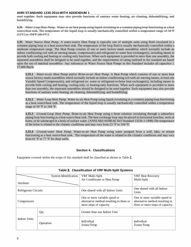
AHRI STANDARD 1230-2014-WITH ADDENDUM 1 ______________________________________________
8
used together. Such equipment may also provide functions of sanitary water heating, air cleaning, dehumidifying, and
humidifying.
3.31 Water Loop Heat Pump. Water-to-air heat pump using liquid circulating in a common piping loop functioning as a heat
source/heat sink. The temperature of the liquid loop is usually mechanically controlled within a temperature range of 59°F
[15°C] to 104°F [40.0°C].
3.35 Water Source Heat Pump. A water-source Heat Pump is typically one of multiple units using fluid circulated in a
common piping loop as a heat source/heat sink. The temperature of the loop fluid is usually mechanically controlled within a
moderate temperature range. The Heat Pump consists of one or more factory-made assemblies which normally include an
indoor conditioning coil with air moving means, compressor(s) and refrigerant-to-water heat exchanger(s), including means to provide both cooling and heating or cooling only functions. When such equipment is provided in more than one assembly, the
separated assemblies shall be designed to be used together, and the requirements of rating outlined in the standard are based
upon the use of matched assemblies. Any references to Water Source Heat Pumps in this Standard includes all capacities ≥
17,000 Btu/h.
3.35.1 Water-to-air Heat Pump and/or Brine-to-air Heat Pump. A Heat Pump which consists of one or more heat
source factory-made assemblies which normally include an indoor conditioning coil with air-moving means, at least one
Variable Speed Compressor(s), and refrigerant-to- water or refrigerant-to-brine heat exchanger(s), including means to
provide both cooling and heating, cooling-only, or heating-only functions. When such equipment is provided in more
than one assembly, the separated assemblies should be designed to be used together. Such equipment may also provide
functions of sanitary water heating, air cleaning, dehumidifying, and humidifying.
3.35.2 Water Loop Heat Pump. Water-to-air Heat Pump using liquid circulating in a common piping loop functioning
as a heat source/heat sink. The temperature of the liquid loop is usually mechanically controlled within a temperature
range of 59 °F to 104 °F.
3.35.3 Ground-Loop Heat Pump. Brine-to-air Heat Pump using a brine solution circulating through a subsurface
piping loop functioning as a heat source/heat sink. The heat exchange loop may be placed in horizontal trenches, vertical bores, or be submerged in a body of surface water. (ANSI/ARI/ASHRAE ISO Standard 13256-1:1998) The temperature
of the brine is related to the climatic conditions and may vary from 23 °F to 104 °F.
3.35.4 Ground-water Heat Pump. Water-to-air Heat Pump using water pumped from a well, lake, or stream
functioning as a heat source/heat sink. The temperature of the water is related to the climatic conditions and may vary
from 41 °F to 77 °F for deep wells.
Section 4. Classifications
Equipment covered within the scope of this standard shall be classified as shown in Table 2.
Table 2. Classification of VRF Multi-Split Systems
System Identification
Attribute
VRF Multi-Split
Air Conditioner or Heat Pump
VRF Heat Recovery
Multi-Split
Refrigerant Circuits One shared with all Indoor Units One shared with all Indoor
Units
Compressors
One or more variable speed or
alternative method resulting in three or
more steps of capacity.
One or more variable speed or
alternative method resulting in
three or more steps of capacity.
Indoor Units
Qty. Greater than one Indoor Unit
Operation Individual
Zones/Temp
Individual
Zones/Temp
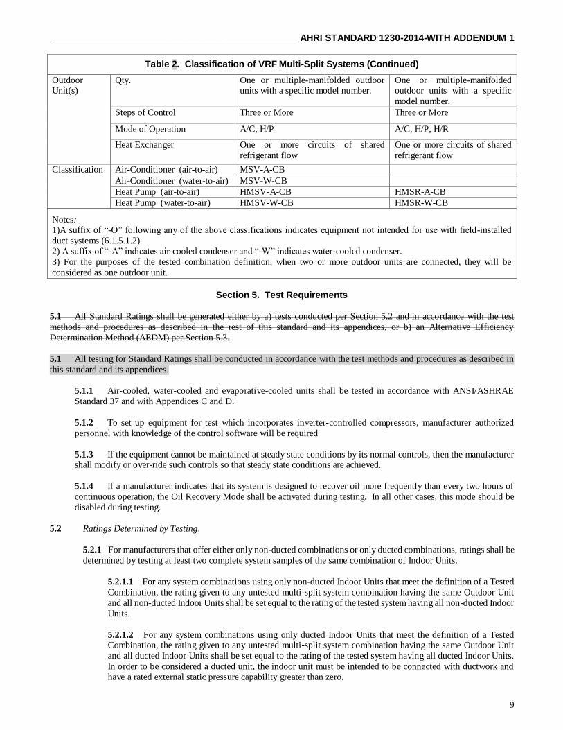
______________________________________________ AHRI STANDARD 1230-2014-WITH ADDENDUM 1
9
Table 2. Classification of VRF Multi-Split Systems (Continued)
Outdoor Unit(s)
Qty. One or multiple-manifolded outdoor units with a specific model number.
One or multiple-manifolded outdoor units with a specific
model number.
Steps of Control Three or More Three or More
Mode of Operation A/C, H/P A/C, H/P, H/R
Heat Exchanger One or more circuits of shared
refrigerant flow
One or more circuits of shared
refrigerant flow
Classification Air-Conditioner (air-to-air) MSV-A-CB
Air-Conditioner (water-to-air) MSV-W-CB
Heat Pump (air-to-air) HMSV-A-CB HMSR-A-CB
Heat Pump (water-to-air) HMSV-W-CB HMSR-W-CB
Notes: 1)A suffix of “-O” following any of the above classifications indicates equipment not intended for use with field-installed
duct systems (6.1.5.1.2).
2) A suffix of “-A” indicates air-cooled condenser and “-W” indicates water-cooled condenser.
3) For the purposes of the tested combination definition, when two or more outdoor units are connected, they will be
considered as one outdoor unit.
Section 5. Test Requirements
5.1 All Standard Ratings shall be generated either by a) tests conducted per Section 5.2 and in accordance with the test
methods and procedures as described in the rest of this standard and its appendices, or b) an Alternative Efficiency
Determination Method (AEDM) per Section 5.3.
5.1 All testing for Standard Ratings shall be conducted in accordance with the test methods and procedures as described in
this standard and its appendices.
5.1.1 Air-cooled, water-cooled and evaporative-cooled units shall be tested in accordance with ANSI/ASHRAE
Standard 37 and with Appendices C and D.
5.1.2 To set up equipment for test which incorporates inverter-controlled compressors, manufacturer authorized
personnel with knowledge of the control software will be required
5.1.3 If the equipment cannot be maintained at steady state conditions by its normal controls, then the manufacturer shall modify or over-ride such controls so that steady state conditions are achieved.
5.1.4 If a manufacturer indicates that its system is designed to recover oil more frequently than every two hours of
continuous operation, the Oil Recovery Mode shall be activated during testing. In all other cases, this mode should be
disabled during testing.
5.2 Ratings Determined by Testing.
5.2.1 For manufacturers that offer either only non-ducted combinations or only ducted combinations, ratings shall be
determined by testing at least two complete system samples of the same combination of Indoor Units.
5.2.1.1 For any system combinations using only non-ducted Indoor Units that meet the definition of a Tested
Combination, the rating given to any untested multi-split system combination having the same Outdoor Unit
and all non-ducted Indoor Units shall be set equal to the rating of the tested system having all non-ducted Indoor
Units.
5.2.1.2 For any system combinations using only ducted Indoor Units that meet the definition of a Tested Combination, the rating given to any untested multi-split system combination having the same Outdoor Unit
and all ducted Indoor Units shall be set equal to the rating of the tested system having all ducted Indoor Units.
In order to be considered a ducted unit, the indoor unit must be intended to be connected with ductwork and
have a rated external static pressure capability greater than zero.
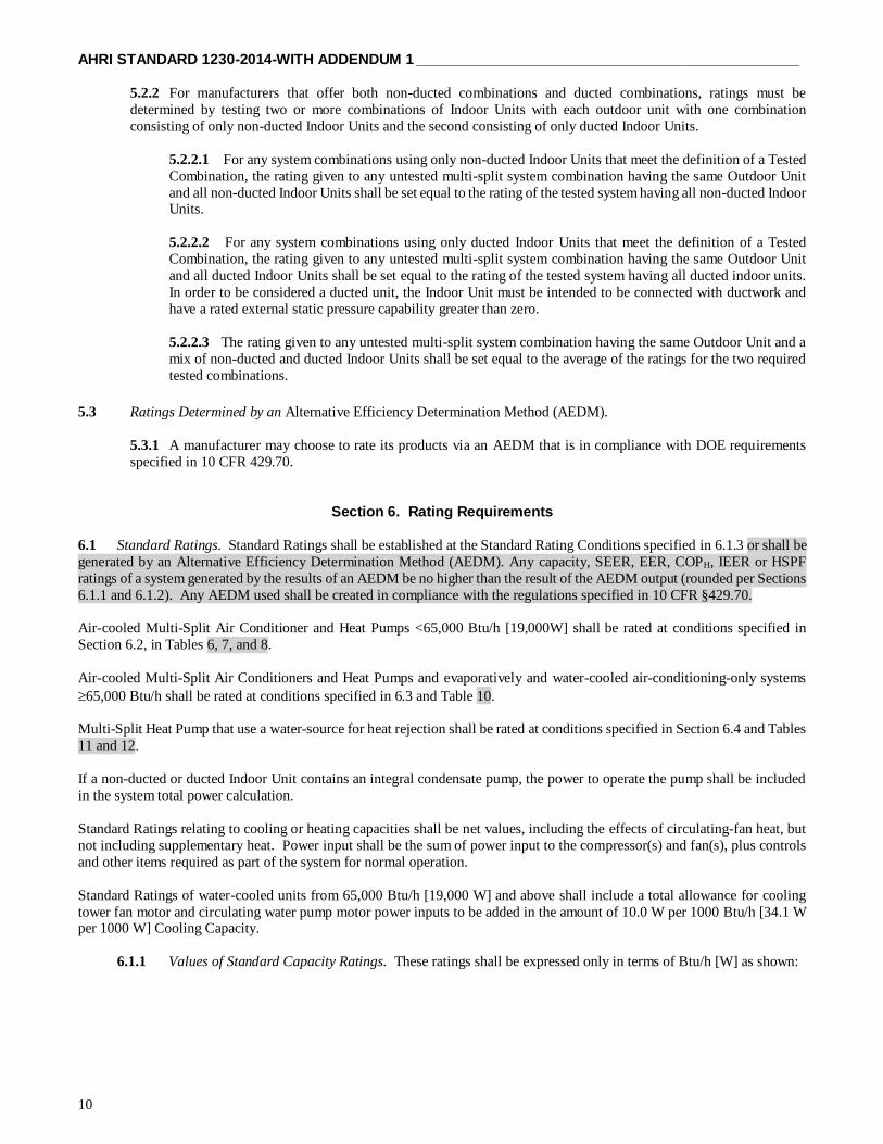
AHRI STANDARD 1230-2014-WITH ADDENDUM 1 ______________________________________________
10
5.2.2 For manufacturers that offer both non-ducted combinations and ducted combinations, ratings must be
determined by testing two or more combinations of Indoor Units with each outdoor unit with one combination
consisting of only non-ducted Indoor Units and the second consisting of only ducted Indoor Units.
5.2.2.1 For any system combinations using only non-ducted Indoor Units that meet the definition of a Tested
Combination, the rating given to any untested multi-split system combination having the same Outdoor Unit
and all non-ducted Indoor Units shall be set equal to the rating of the tested system having all non-ducted Indoor Units.
5.2.2.2 For any system combinations using only ducted Indoor Units that meet the definition of a Tested
Combination, the rating given to any untested multi-split system combination having the same Outdoor Unit
and all ducted Indoor Units shall be set equal to the rating of the tested system having all ducted indoor units.
In order to be considered a ducted unit, the Indoor Unit must be intended to be connected with ductwork and
have a rated external static pressure capability greater than zero.
5.2.2.3 The rating given to any untested multi-split system combination having the same Outdoor Unit and a
mix of non-ducted and ducted Indoor Units shall be set equal to the average of the ratings for the two required
tested combinations.
5.3 Ratings Determined by an Alternative Efficiency Determination Method (AEDM).
5.3.1 A manufacturer may choose to rate its products via an AEDM that is in compliance with DOE requirements
specified in 10 CFR 429.70.
Section 6. Rating Requirements
6.1 Standard Ratings. Standard Ratings shall be established at the Standard Rating Conditions specified in 6.1.3 or shall be
generated by an Alternative Efficiency Determination Method (AEDM). Any capacity, SEER, EER, COPH, IEER or HSPF
ratings of a system generated by the results of an AEDM be no higher than the result of the AEDM output (rounded per Sections
6.1.1 and 6.1.2). Any AEDM used shall be created in compliance with the regulations specified in 10 CFR §429.70.
Air-cooled Multi-Split Air Conditioner and Heat Pumps <65,000 Btu/h [19,000W] shall be rated at conditions specified in
Section 6.2, in Tables 6, 7, and 8.
Air-cooled Multi-Split Air Conditioners and Heat Pumps and evaporatively and water-cooled air-conditioning-only systems
65,000 Btu/h shall be rated at conditions specified in 6.3 and Table 10.
Multi-Split Heat Pump that use a water-source for heat rejection shall be rated at conditions specified in Section 6.4 and Tables
11 and 12.
If a non-ducted or ducted Indoor Unit contains an integral condensate pump, the power to operate the pump shall be included
in the system total power calculation.
Standard Ratings relating to cooling or heating capacities shall be net values, including the effects of circulating-fan heat, but
not including supplementary heat. Power input shall be the sum of power input to the compressor(s) and fan(s), plus controls
and other items required as part of the system for normal operation.
Standard Ratings of water-cooled units from 65,000 Btu/h [19,000 W] and above shall include a total allowance for cooling
tower fan motor and circulating water pump motor power inputs to be added in the amount of 10.0 W per 1000 Btu/h [34.1 W per 1000 W] Cooling Capacity.
6.1.1 Values of Standard Capacity Ratings. These ratings shall be expressed only in terms of Btu/h [W] as shown:
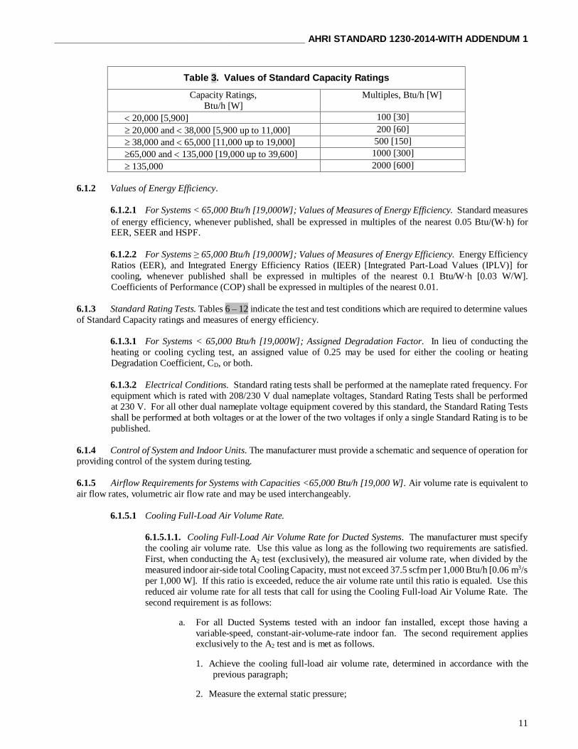
______________________________________________ AHRI STANDARD 1230-2014-WITH ADDENDUM 1
11
Table 3. Values of Standard Capacity Ratings
Capacity Ratings,
Btu/h [W]
Multiples, Btu/h [W]
20,000 [5,900] 100 [30]
20,000 and 38,000 [5,900 up to 11,000] 200 [60]
38,000 and 65,000 [11,000 up to 19,000] 500 [150]
65,000 and 135,000 [19,000 up to 39,600] 1000 [300]
135,000 2000 [600]
6.1.2 Values of Energy Efficiency.
6.1.2.1 For Systems < 65,000 Btu/h [19,000W]; Values of Measures of Energy Efficiency. Standard measures
of energy efficiency, whenever published, shall be expressed in multiples of the nearest 0.05 Btu/(Wh) for EER, SEER and HSPF.
6.1.2.2 For Systems ≥ 65,000 Btu/h [19,000W]; Values of Measures of Energy Efficiency. Energy Efficiency
Ratios (EER), and Integrated Energy Efficiency Ratios (IEER) [Integrated Part-Load Values (IPLV)] for
cooling, whenever published shall be expressed in multiples of the nearest 0.1 Btu/W·h [0.03 W/W].
Coefficients of Performance (COP) shall be expressed in multiples of the nearest 0.01.
6.1.3 Standard Rating Tests. Tables 6 – 12 indicate the test and test conditions which are required to determine values
of Standard Capacity ratings and measures of energy efficiency.
6.1.3.1 For Systems < 65,000 Btu/h [19,000W]; Assigned Degradation Factor. In lieu of conducting the
heating or cooling cycling test, an assigned value of 0.25 may be used for either the cooling or heating
Degradation Coefficient, CD, or both.
6.1.3.2 Electrical Conditions. Standard rating tests shall be performed at the nameplate rated frequency. For
equipment which is rated with 208/230 V dual nameplate voltages, Standard Rating Tests shall be performed
at 230 V. For all other dual nameplate voltage equipment covered by this standard, the Standard Rating Tests
shall be performed at both voltages or at the lower of the two voltages if only a single Standard Rating is to be
published.
6.1.4 Control of System and Indoor Units. The manufacturer must provide a schematic and sequence of operation for
providing control of the system during testing.
6.1.5 Airflow Requirements for Systems with Capacities <65,000 Btu/h [19,000 W]. Air volume rate is equivalent to
air flow rates, volumetric air flow rate and may be used interchangeably.
6.1.5.1 Cooling Full-Load Air Volume Rate.
6.1.5.1.1. Cooling Full-Load Air Volume Rate for Ducted Systems. The manufacturer must specify
the cooling air volume rate. Use this value as long as the following two requirements are satisfied.
First, when conducting the A2 test (exclusively), the measured air volume rate, when divided by the
measured indoor air-side total Cooling Capacity, must not exceed 37.5 scfm per 1,000 Btu/h [0.06 m3/s
per 1,000 W]. If this ratio is exceeded, reduce the air volume rate until this ratio is equaled. Use this
reduced air volume rate for all tests that call for using the Cooling Full-load Air Volume Rate. The
second requirement is as follows:
a. For all Ducted Systems tested with an indoor fan installed, except those having a
variable-speed, constant-air-volume-rate indoor fan. The second requirement applies exclusively to the A2 test and is met as follows.
1. Achieve the cooling full-load air volume rate, determined in accordance with the
previous paragraph;
2. Measure the external static pressure;
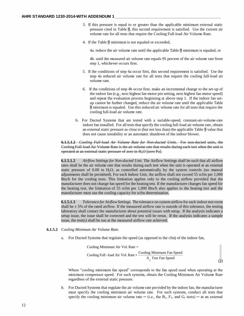
AHRI STANDARD 1230-2014-WITH ADDENDUM 1 ______________________________________________
12
3. If this pressure is equal to or greater than the applicable minimum external static
pressure cited in Table 9, this second requirement is satisfied. Use the current air
volume rate for all tests that require the Cooling Full-load Air Volume Rate.
4. If the Table 9 minimum is not equaled or exceeded,
4a. reduce the air volume rate until the applicable Table 9 minimum is equaled, or
4b. until the measured air volume rate equals 95 percent of the air volume rate from
step 1, whichever occurs first.
5. If the conditions of step 4a occur first, this second requirement is satisfied. Use the
step 4a reduced air volume rate for all tests that require the cooling full-load air
volume rate.
6. If the conditions of step 4b occur first, make an incremental change to the set-up of
the indoor fan (e.g., next highest fan motor pin setting, next highest fan motor speed)
and repeat the evaluation process beginning at above step 1. If the indoor fan set-
up cannot be further changed, reduce the air volume rate until the applicable Table 9 minimum is equaled. Use this reduced air volume rate for all tests that require the
cooling full-load air volume rate.
b. For Ducted Systems that are tested with a variable-speed, constant-air-volume-rate
indoor fan installed. For all tests that specify the cooling full-load air volume rate, obtain
an external static pressure as close to (but not less than) the applicable Table 9 value that
does not cause instability or an automatic shutdown of the indoor blower.
6.1.5.1.2 Cooling Full-load Air Volume Rate for Non-ducted Units. For non-ducted units, the
Cooling Full-load Air Volume Rate is the air volume rate that results during each test when the unit is
operated at an external static pressure of zero in H2O [zero Pa].
6.1.5.1.2 Airflow Settings for Non-ducted Unit. The Airflow Settings shall be such that all airflow
rates shall be the air volume rate that results during each test when the unit is operated at an external
static pressure of 0.00 in H2O, as controlled automatically by the system controls (no manual
adjustments shall be permitted). For each Indoor Unit, the airflow shall not exceed 55 scfm per 1,000
Btu/h for the cooling tests. This limitation applies only to the cooling airflow provided that the
manufacturer does not change fan speed for the heating test. If the manufacturer changes fan speed for
the heating test, the limitation of 55 scfm per 1,000 Btu/h also applies to the heating test and the
manufacturer must use the cooling capacity for scfm determination.
6.1.5.1.3 Tolerance for Airflow Settings. The tolerance on system airflow for each indoor test room
shall be ± 5% of the rated airflow. If the measured airflow rate is outside of this tolerance, the testing
laboratory shall contact the manufacturer about potential issues with setup. If the analysis indicates a
setup issue, the issue shall be corrected and the test will be rerun. If the analysis indicates a sample
issue, the test(s) shall be run at the measured airflow rate achieved.
6.1.5.2 Cooling Minimum Air Volume Rate.
a. For Ducted Systems that regulate the speed (as opposed to the cfm) of the indoor fan,
2
Cooling Minimum Air Vol. Rate =
Cooling Minimum Fan SpeedCooling Full - load Air Vol. Rate ×
A Test Fan Speed (2)
Where “cooling minimum fan speed” corresponds to the fan speed used when operating at the
minimum compressor speed. For such systems, obtain the Cooling Minimum Air Volume Rate
regardless of the external static pressure.
b. For Ducted Systems that regulate the air volume rate provided by the indoor fan, the manufacturer
must specify the cooling minimum air volume rate. For such systems, conduct all tests that
specify the cooling minimum air volume rate ─ (i.e., the B1, F1, and G1 tests) ─ at an external

______________________________________________ AHRI STANDARD 1230-2014-WITH ADDENDUM 1
13
static pressure that does not cause instability or an automatic shutdown of the indoor blower while
being as close to, but not less than,
2
2
st1 1 1 1 1 st,A
Cooling Minimum Air Volume RateA , B , C , F , and G Test ΔP ΔP
Cooling Full load Air Volume Rate
(3)
where 2
st,AΔP is the applicable Table 9 minimum external static pressure that was targeted during
the A2 (and B2) test.
c. For Non-ducted systems, the Cooling Minimum Air Volume Rate is the air volume rate that results during each test when the unit operates at an external static pressure of zero in H2O [zero
Pa] and at the indoor fan setting used at minimum compressor speed.
6.1.5.3 Cooling Intermediate Air Volume Rate.
a. For Ducted Systems that regulate the speed of the indoor fan,
V
2
E Test Fan SpeedCooling Intermediate Air Volume Rate Cooling Full load Air Volume Rate
A Test Fan Speed
(4)
For such units, obtain the Cooling Intermediate Air Volume Rate regardless of the external static
pressure.
b. For Ducted Systems that regulate the air volume rate provided by the indoor fan, the manufacturer
must specify the cooling intermediate air volume rate. For such systems, conduct the EV test at
an external static pressure that does not cause instability or an automatic shutdown of the indoor
blower while being as close to, but not less than,
2
2
V st,A
Cooling Intermediate Air Volume RateE Test ΔP
Cooling Full load Air Volume Rate
(5)
where 2
st,AΔP is the applicable Table 9 minimum external static pressure that was targeted during
the A2 (and B2) test.
c. For Non-ducted Systems, the Cooling Intermediate Air Volume Rate is the air volume rate that
results when the unit operates at an external static pressure of zero in H2O [zero Pa] and at the fan
speed selected by the controls of the unit for the EV test conditions.
6.1.5.4 Heating Full-load Air Volume Rate.
6.1.5.4.1 Ducted Heat Pumps where the Heating and Cooling Full-load Air Volume Rates are the
Same.
a. Use the Cooling Full-load Air Volume Rate as the Heating Full-load Air Volume Rate for:
1. Ducted Heat Pumps that operate at the same indoor fan speed during both the A2
and the H12 tests;
2. Ducted Heat Pumps that regulate fan speed to deliver the same constant air
volume rate during both the A2 and the H12 tests; and
3. The airflow of all of the individual ducted Indoor Units must be added together to
arrive at the full-load air volume rate
B1,
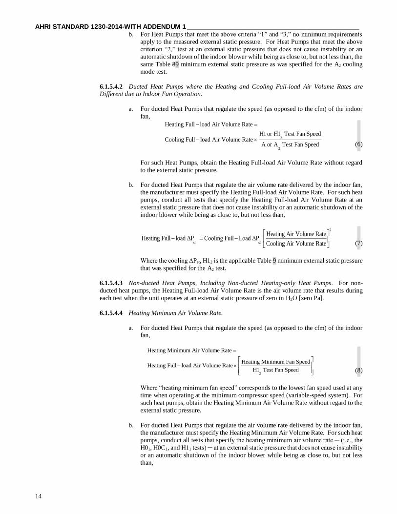
AHRI STANDARD 1230-2014-WITH ADDENDUM 1 ______________________________________________
14
b. For Heat Pumps that meet the above criteria “1” and “3,” no minimum requirements
apply to the measured external static pressure. For Heat Pumps that meet the above
criterion “2,” test at an external static pressure that does not cause instability or an
automatic shutdown of the indoor blower while being as close to, but not less than, the
same Table 89 minimum external static pressure as was specified for the A2 cooling
mode test.
6.1.5.4.2 Ducted Heat Pumps where the Heating and Cooling Full-load Air Volume Rates are Different due to Indoor Fan Operation.
a. For ducted Heat Pumps that regulate the speed (as opposed to the cfm) of the indoor
fan,
2
2
Heating Full load Air Volume Rate
H1 or H1 Test Fan SpeedCooling Full load Air Volume Rate
A or A Test Fan Speed
(6)
For such Heat Pumps, obtain the Heating Full-load Air Volume Rate without regard
to the external static pressure.
b. For ducted Heat Pumps that regulate the air volume rate delivered by the indoor fan,
the manufacturer must specify the Heating Full-load Air Volume Rate. For such heat
pumps, conduct all tests that specify the Heating Full-load Air Volume Rate at an
external static pressure that does not cause instability or an automatic shutdown of the
indoor blower while being as close to, but not less than,
2
st st
Heating Air Volume RateHeating Full load ΔP Cooling Full Load ΔP
Cooling Air Volume Rate
(7)
Where the cooling ΔPst, H12 is the applicable Table 9 minimum external static pressure
that was specified for the A2 test.
6.1.5.4.3 Non-ducted Heat Pumps, Including Non-ducted Heating-only Heat Pumps. For non-
ducted heat pumps, the Heating Full-load Air Volume Rate is the air volume rate that results during
each test when the unit operates at an external static pressure of zero in H2O [zero Pa].
6.1.5.4.4 Heating Minimum Air Volume Rate.
a. For ducted Heat Pumps that regulate the speed (as opposed to the cfm) of the indoor fan,
2
Heating Minimum Air Volume Rate
Heating Minimum Fan SpeedHeating Full load Air Volume Rate
H1 Test Fan Speed
(8)
Where “heating minimum fan speed” corresponds to the lowest fan speed used at any
time when operating at the minimum compressor speed (variable-speed system). For
such heat pumps, obtain the Heating Minimum Air Volume Rate without regard to the
external static pressure.
b. For ducted Heat Pumps that regulate the air volume rate delivered by the indoor fan,
the manufacturer must specify the Heating Minimum Air Volume Rate. For such heat
pumps, conduct all tests that specify the heating minimum air volume rate ─ (i.e., the
H01, H0C1, and H11 tests) ─ at an external static pressure that does not cause instability
or an automatic shutdown of the indoor blower while being as close to, but not less
than,

______________________________________________ AHRI STANDARD 1230-2014-WITH ADDENDUM 1
15
2
2
1 1 1 1 st,H1
Heating Minimum Air Volume RateH0 , H1 , H2 , H3 Test P
Heating Full load Air Volume Rate
(9)
Where 2
st,H1ΔP is the minimum external static pressure that was targeted during the
H12 test.
c. For non-ducted Heat Pumps, the Heating Minimum Air Volume Rate is the air volume
rate that results during each test when the unit operates at an external static pressure
of zero in H2O [zero Pa] and at the indoor fan setting used at minimum compressor
speed.
6.1.5.4.5 Heating Intermediate Air Volume Rate.
a. For ducted heat pumps that regulate the speed of the indoor fan,
V
2
Heating Intermediate Air Volume Rate =
H2 Test Fan SpeedHeating Air Volume Rate ×
H1 Test Fan SpeedFull load
(10)
For such heat pumps, obtain the Heating Intermediate Air Volume Rate without regard
to the external static pressure.
b. For ducted Heat Pumps that regulate the air volume rate delivered by the indoor fan,
the manufacturer must specify the Heating Intermediate Air Volume Rate. For such
heat pumps, conduct the H2V test at an external static pressure that does not cause
instability or an automatic shutdown of the indoor blower while being as close to, but
not less than,
2
2
V st, H1
Heating Intermediate Air Volume RateH2 Test ΔP =
Heating Air Volume RateFull load
(11)
Where 2
st, H1ΔP is the minimum external static pressure that was specified for the H12
test.
c. For non-ducted heat pumps, the Heating Intermediate Air Volume Rate is the air
volume rate that results when the heat pump operates at an external static pressure of
zero in H2O [zero Pa] and at the fan speed selected by the controls of the unit for the
H2V test conditions.
6.1.5.4.6 Heating Nominal Air Volume Rate. Except for the noted changes, determine the Heating
Nominal Air Volume Rate using the approach described in section 6.1.5.4.5. Required changes
include substituting “H1N test” for “H2V test” within Equation (10), substituting “H1N test ΔPst” for
“H2V test ΔPst” in the second section 6.1.5.4.5 equation, substituting “H1N test” for each “H2V test”, and substituting “Heating Nominal Air Volume Rate” for each “Heating Intermediate Air Volume
Rate.”
V
2
Heating Intermediate Air Volume Rate =
H2 Test Fan SpeedHeating Air Volume Rate ×
H1 Test Fan SpeedFull load
(12)
2
2
N st st,H1
Heating Nominal Air Volume RateH1 Test ΔP = ΔP ×
Heating Air Volume RateFull load
(13)
H0C1

AHRI STANDARD 1230-2014-WITH ADDENDUM 1 ______________________________________________
16
6.1.6 Outdoor-Coil Airflow Rate (Applies to all Air-to-Air Systems). All Standard Ratings shall be determined at the
outdoor-coil airflow rate specified by the manufacturer where the fan drive is adjustable. Where the fan drive is non-
adjustable, ratings shall be determined at the outdoor-coil airflow rate inherent in the equipment when operated with all
of the resistance elements associated with inlets, louvers, and any ductwork and attachments considered by the
manufacturer as normal installation practice. Once established, the outdoor coil air circuit of the equipment shall remain
unchanged throughout all tests prescribed herein.
6.1.7 Requirements for Separated Assemblies (Applies to all Systems). All standard ratings for equipment in which the condenser and the evaporator are two separate assemblies, as in Types: MSV-A-CB, MSV-W-CB, HMSV-A-CB,
HMSV-W-CB, HMSR-A-CB, (See Table 1 Notes) and HMSR-W-CB, shall be obtained with a minimum 25 ft. [7.6 m]
of interconnecting tubing length (for one indoor unit with additional length requirements for each additional unit). Refer
to Table 3 for minimum total refrigerant tube lengths. Refer to Table 4 for Cooling Capacity correction factors that shall
be used when the refrigerant line length exceeds the minimum values provided in Table 3. The complete length of tubing
furnished as an integral part of the unit (and not recommended for cutting to length) shall be used in the test procedure,
or with 25 ft [7.6 m] of refrigerant path, whichever is greater. At least 10 ft [3.0 m] of the system interconnection tubing
shall be exposed to the outside conditions. The line diameters, insulation, installation details, evacuation and charging
shall follow the manufacturer’s published recommendations. The manufacturer will provide a schematic of the tested
combination installation (See Figure 1).
6.1.7 Requirements for Separated Assemblies (Applies to all Systems). For the equipment in product types MSV-A-
CB, MSV-W-CB, HMSV-A-CB, HMSV-W-CB, HMSR-A-CB, (See Table 2 Notes) and HMSR-W-CB, the Indoor
Units and Outdoor Unit are in two separate assemblies.
6.1.7.1 The Indoor Units and Outdoor Unit shall be installed in the laboratory with a minimum 25 ft. of
interconnecting tubing length (for one Indoor Unit with additional length requirements for each additional unit). Refer to Table 4 for minimum total refrigerant tube lengths. Refer to Table 5 for Cooling Capacity correction
factors that shall be used when the tested refrigerant line length exceeds the minimum values provided in Table
4.
6.1.7.2 The complete length of tubing furnished as an integral part of the unit (and not recommended for
cutting to length) shall be used in the test procedure, or with 25 ft of refrigerant path, whichever is greater. At
least 10 ft of the system interconnection tubing shall be exposed to the outside conditions. The line diameters,
insulation, installation details, evacuation and charging shall follow the manufacturer’s published
recommendations. The manufacturer will provide a schematic of the Tested Combination installation (See
Figure 1). To minimize performance degradation, all excess copper tubing shall be coiled in a space in the
laboratory where the coils will not be distributed. The coils shall be horizontal with a minimum diameter of 2
feet. The coils shall be in a place where the manufacturer may check the copper tubing for any potential issues.
6.1.7.3 For systems with multiple outdoor modules, the modules shall be arranged in a straight line where
practical and placed with a spacing of 2 feet (± 3 in.) between them, unless the manufacturer specifies a greater
minimum spacing in their outdoor unit instruction manual. If a single outdoor laboratory section will not
accommodate the straight alignment of the outdoor modules, then an L-shaped configuration shall be attempted. If an L-shaped configuration is not possible, then a second outdoor laboratory section shall be used.
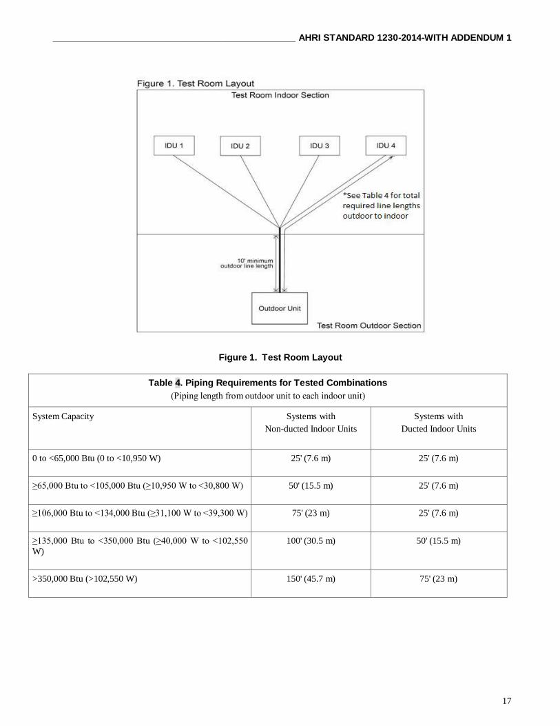
______________________________________________ AHRI STANDARD 1230-2014-WITH ADDENDUM 1
17
Figure 1. Test Room Layout
Table 4. Piping Requirements for Tested Combinations
(Piping length from outdoor unit to each indoor unit)
System Capacity Systems with
Non-ducted Indoor Units
Systems with
Ducted Indoor Units
0 to <65,000 Btu (0 to <10,950 W) 25' (7.6 m) 25' (7.6 m)
≥65,000 Btu to <105,000 Btu (≥10,950 W to <30,800 W) 50' (15.5 m) 25' (7.6 m)
≥106,000 Btu to <134,000 Btu (≥31,100 W to <39,300 W) 75' (23 m) 25' (7.6 m)
≥135,000 Btu to <350,000 Btu (≥40,000 W to <102,550
W) 100' (30.5 m) 50' (15.5 m)
>350,000 Btu (>102,550 W) 150' (45.7 m) 75' (23 m)

AHRI STANDARD 1230-2014-WITH ADDENDUM 1 ______________________________________________
18
Table 4. Refrigerant Line Length Correction Factors
Piping length beyond the
requirement (X), ft [m]
Cooling Capacity Correction
Factor
3.3 [1] < X ≤ 20 [6.1] 1.01
20 [6.1] < X ≤ 40 [12.2] 1.02
40 [12.2] < X ≤ 60 [18.3] 1.03
60 [18.3] < X ≤ 80 [24.4] 1.04
80 [24.4] < X ≤ 100 [30.5] 1.05
100 [30.5] < X ≤ 120 [36.6] 1.06
Note: Due to the refrigerant line lengths required in the test setup, a
correction factor must be applied to normalize the measured cooling
capacity
Table 5. Refrigerant Line Length Correction Factors1, 2, 3
Piping length beyond the requirement (X), ft Cooling Capacity Correction Factor
3.3 < X ≤ 20 1.01
20 < X ≤ 40 1.02
40 < X ≤ 60 1.03
60 < X ≤ 80 1.04
80 < X ≤ 100 1.05
100 < X ≤ 120 1.06
Note:
1. Due to the refrigerant line lengths required in the test setup, the tested capacity must be multiplied
by the correction factor to yield the final capacity result.
2. The piping length X is the cumulative additional line length above the minimum.
3. The absolute minimum length necessary to physically connect the system shall be used.
6.2 Conditions for Standard Rating Test for Air-cooled Systems < 65,000 Btu/h [19,000W].
6.2.1 Instructions for Multiple Indoor Unit Testing.
a. At least one indoor unit must be turned off for tests conducted at minimum compressor speed. In addition,
the manufacturer may elect to have one or more Indoor Units turned off for tests conducted at the
intermediate compressor speed. In all cases, the manufacturer specifies the particular Indoor Unit(s) that is
turned off.
6.2.2 Compressor Speed. The speed at which the compressor runs to deliver the capacity of the tested combination.
6.2.2.1 Maximum Compressor Speed. Manufacturers shall designate the maximum compressor speed. The
maximum compressor speed for cooling mode tests is a fixed value. The maximum compressor speed for
heating mode tests is also a fixed value that may be the same or different from the cooling mode value.
6.2.2.2 Intermediate Compressor Speed. For each test manufactures will designate the intermediate
compressor speed that falls within ¼ and ¾ of the difference between the minimum and maximum speeds for
both cooling and heating.
6.2.2.3 Minimum Compressor Speed. Manufacturers shall designate the minimum compressor speed at a
steady-state level below which the system would rarely operate. The minimum compressor speed for cooling
mode tests is a fixed value. The minimum compressor speed for heating mode tests is also a fixed value that
may be the same or different from the cooling mode value.

______________________________________________ AHRI STANDARD 1230-2014-WITH ADDENDUM 1
19
6.2.3 Cooling Tests for a Unit Having a Variable-speed Compressor.
a. Conduct five steady-state wet coil tests: the A2, EV, B2, B1, and F1 tests. Use the two optional dry-coil
tests, the steady-state G1 test and the cyclic I1 test, to determine the cooling mode cyclic degradation
coefficient, c
DC . If the two optional tests are not conducted, assign c
DC the default value of 0.25. Table 6
specifies test conditions for these seven tests.
Table 6. Cooling Mode Test Conditions for Units < 65,000 Btu/h [19,000 W]
Test Description
Air Entering Indoor Unit
Temperature
Air Entering Outdoor Unit
Temperature Compressor
Speed
Cooling Air
Volume Rate Dry-Bulb
F [C]
Wet-Bulb
F [C]
Dry-Bulb
F [C]
Wet-Bulb
F [C]
A2 Test - required
(steady, wet coil) 80.0 [26.7] 67.0 [19.4] 95.0 [35.0] 75.01 [23.91] Maximum7
Cooling Full-
load Air
Volume Rate2
B2 Test - required
(steady, wet coil) 80.0 [26.7] 67.0 [19.4] 82.0 [27.8] 65.01 [18.31] Maximum7
Cooling Full-
load Air
Volume Rate2
EV Test - required
(steady, wet coil) 80.0 [26.7] 67.0 [19.4] 87.0 [30.6] 69.01 [20.61] Intermediate8 Cooling
Intermediate3
B1 Test - required
(steady, wet coil) 80.0 [26.7] 67.0 [19.4] 82.0 [27.8] 65.01 [18.31] Minimum9 Cooling
Minimum4
F1 Test - required
(steady, wet coil) 80.0 [26.7] 67.0 [19.4] 67.0 [19.4] 53.51 [11.91] Minimum9
Cooling
Minimum4
G1 Test5 - optional
(steady, dry coil) 80.0 [26.7] 6 67.0 [19.4] NA Minimum9
Cooling
Minimum4
I1 Test5 - optional
(cyclic, dry coil) 80.0 [26.7] 6 67.0 [19.4] NA Minimum9 6
Table 6. Cooling Mode Test Conditions for Units < 65,000 Btu/h [19,000 W] (Continued)
Notes: 1) The specified test condition only applies if the unit rejects condensate to the outdoor coil.
2) Defined in Section 6.1.5.1
3) Defined in Section 6.1.5.3
4) Defined in Section 6.1.5.2
5) The entering air must have a low enough moisture content so no condensate forms on the indoor coil. (It is
recommended that an indoor wet-bulb temperature of 57.0 F [13.9 C] or less be used.) 6) Maintain the airflow nozzles static pressure difference or velocity pressure during the ON period at the same
pressure difference or velocity pressure as measured during the G1 Test.
7) Maximum compressor speed is defined in Section 6.2.2.1.
8) Intermediate compressor speed is defined in Section 6.2.2.2.
9) Minimum compressor speed is defined in Section 6.2.2.3.
6.2.4 Heating Mode Tests for a Heat Pump Having a Variable-speed Compressor.
a. Conduct one maximum temperature test (H01), two high temperature tests (H12 and H11), one frost
accumulation test (H2V), and one low temperature test (H32). Conducting one or both of the following
tests is optional: an additional high temperature test (H1N ) and an additional frost accumulation test (H22).
Conduct the optional maximum temperature cyclic (H0C1) test to determine the heating mode cyclic
degradation coefficient, h
DC . If this optional test is not conducted, assign h
DC the default value of 0.25.
Table 7 specifies test conditions for these eight tests.
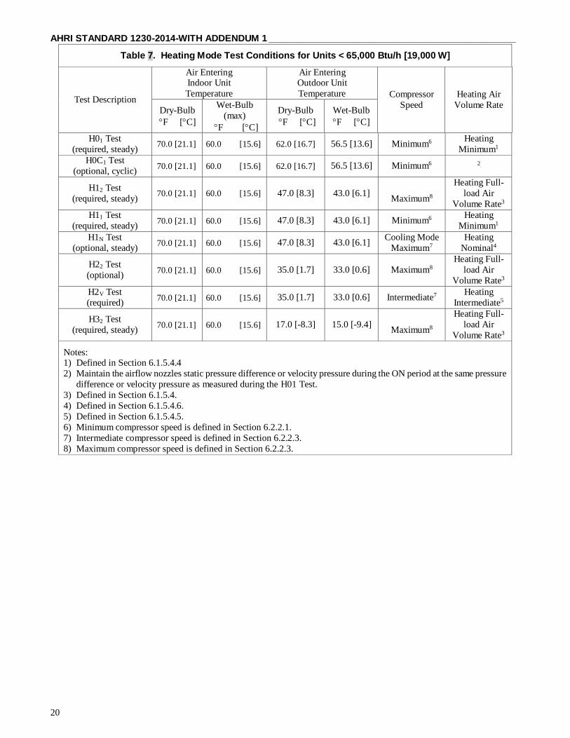
AHRI STANDARD 1230-2014-WITH ADDENDUM 1 ______________________________________________
20
Table 7. Heating Mode Test Conditions for Units < 65,000 Btu/h [19,000 W]
Test Description
Air Entering Indoor Unit
Temperature
Air Entering Outdoor Unit
Temperature Compressor
Speed
Heating Air
Volume Rate Dry-Bulb
F [C]
Wet-Bulb
(max)
F [C]
Dry-Bulb
F [C]
Wet-Bulb
F [C]
H01 Test
(required, steady) 70.0 [21.1] 60.0 [15.6] 62.0 [16.7] 56.5 [13.6] Minimum6
Heating
Minimum1
H0C1 Test
(optional, cyclic) 70.0 [21.1] 60.0 [15.6] 62.0 [16.7] 56.5 [13.6] Minimum6 2
H12 Test
(required, steady) 70.0 [21.1] 60.0 [15.6] 47.0 [8.3] 43.0 [6.1]
Maximum8
Heating Full-
load Air
Volume Rate3
H11 Test
(required, steady) 70.0 [21.1] 60.0 [15.6] 47.0 [8.3] 43.0 [6.1] Minimum6
Heating
Minimum1
H1N Test
(optional, steady) 70.0 [21.1] 60.0 [15.6] 47.0 [8.3] 43.0 [6.1]
Cooling Mode
Maximum7
Heating
Nominal4
H22 Test
(optional) 70.0 [21.1] 60.0 [15.6] 35.0 [1.7] 33.0 [0.6] Maximum8
Heating Full-
load Air
Volume Rate3
H2V Test
(required) 70.0 [21.1] 60.0 [15.6] 35.0 [1.7] 33.0 [0.6] Intermediate7
Heating
Intermediate5
H32 Test
(required, steady) 70.0 [21.1] 60.0 [15.6] 17.0 [-8.3] 15.0 [-9.4]
Maximum8
Heating Full-
load Air
Volume Rate3
Notes: 1) Defined in Section 6.1.5.4.4
2) Maintain the airflow nozzles static pressure difference or velocity pressure during the ON period at the same pressure
difference or velocity pressure as measured during the H01 Test.
3) Defined in Section 6.1.5.4.
4) Defined in Section 6.1.5.4.6.
5) Defined in Section 6.1.5.4.5.
6) Minimum compressor speed is defined in Section 6.2.2.1.
7) Intermediate compressor speed is defined in Section 6.2.2.3.
8) Maximum compressor speed is defined in Section 6.2.2.3.

______________________________________________ AHRI STANDARD 1230-2014-WITH ADDENDUM 1
21
Table 8. Conditions for Operating Requirement Tests for Air-Cooled Equipment < 65,000 Btu/h [19,000 W]
Test
Indoor Unit
Outdoor Unit
Air Entering Temperature
Air Entering Temperature
Dry-Bulb
F [C]
Wet-Bulb
F [C]
Dry-Bulb
F [C]
Wet-Bulb
F [C]
Cooli
ng
Voltage Tolerance
80.0 [26.7]
67.0 [19.4]
95.0 [35.0]
75.01 [23.9]
Low Temperature Operation
Cooling
67.0 [19.4]
57.0 [13.9]
67.0 [19.4]
57.01 [13.9]
Insulation Efficiency
80.0 [26.7]
75.0 [23.9]
80.0 [26.7]
75.01 [23.9]
Condensate Disposal
80.0 [26.7]
75.0 [23.9]
80.0 [26.7]
75.01 [23.9]
Maximum Operating Conditions
80.0 [26.7]
67.0 [19.4]
115.0 [46.1]
75.01 [23.9]
Hea
tin
g
Voltage Tolerance (Heating-only
units)
70.0 [21.1]
60.0 [15.6]
(max)
47.0 [8.3]
43.0 [6.1]
Maximum Operating Conditions
80.0 [26.7]
NA NA
75.0 [23.9]
65.0 [18.3]
Note:
1) The wet-bulb temperature condition is not required when testing air-cooled condensers which do not evaporate
condensate.
Table 9. Minimum External Static Pressure for Ducted Systems Tested with External Static Pressure > 0 in H2O
Rated Cooling1 or Heating2 Capacity
Minimum External Resistance3,4
Small-duct High-velocity
Systems5 All Other Systems
Btu/h kW in H2O Pa in H2O Pa
Up through 28,800 6.40 to 8.44 1.10 275 0.10 25
29,000 to 42,500 8.5 to 12.4 1.15 388 0.15 37
43,000 thru 60,000 12.6 thru 19.0 1.20 300 0.20 50
Notes:
1) For air conditioners and heat pumps, the value cited by the manufacturer in published literature for the unit’s Capacity
when operated at the A2 Test conditions.
2) For heating-only heat pumps, the value the manufacturer cites in published literature for the unit’s Capacity when operated
at the H12 Test conditions.
3) For Ducted Systems tested without an air filter installed, increase the applicable tabular value by 0.08 in H2O [20 Pa].
4) If the manufacturer’s rated external static pressure is less than 0.10 in H2O (25 Pa), then the Indoor Unit should be tested
at that rated external static pressure. (See Section 5.2.1.2)
5) See Definition 1.35 of Appendix C to determine if the equipment qualifies as a Small-duct, High-velocity System.

AHRI STANDARD 1230-2014-WITH ADDENDUM 1 ______________________________________________
22
6.3 Conditions for Standard Rating Test for Air-cooled Air Conditioner and Heat Pump Systems and Water-cooled Air
Conditioning Systems ≥ 65,000 Btu/h [19,000W].
6.3.1 Indoor-Coil Airflow Rate. All Standard Ratings shall be determined at an indoor-coil airflow rate as outlined
below. All airflow rates shall be expressed in terms of Standard Air.
a. Equipment with indoor fans intended for use with field installed duct systems shall be rated at the
manufacturer specified airflow rate (not to exceed 37.5 scfm per 1000 Btu/h [0.06 m3/s per 1000 W] of Rated Capacity) while meeting or exceeding the minimum external resistance specified in Table 7.
b. Equipment with indoor fans not intended for use with field installed duct systems (free discharge) shall be
rated at the indoor-side air quantity delivered when operating at zero in H2O [zero Pa] external pressure.
c. 100% recirculated air shall be used.
d. Equipment which does not incorporate an indoor fan is not covered in this standard.
e. Indoor-coil airflow rates and pressures as referred to herein apply to the airflow rate experienced when the
unit is cooling and dehumidifying under the conditions specified in this section. This airflow rate, except
as noted in 6.3.1b and 8.8 shall be employed in all other tests prescribed herein without regard to resultant
external static pressure.
f. All airflow rates shall be the air volume rate that results during each test when the unit is operated at an
external static pressure of 0.00 in H2O, as controlled automatically by the system controls (no manual
adjustments shall be permitted). For each Indoor Unit, the airflow shall not exceed 55 scfm per 1,000 Btu/h for the cooling tests. This limitation applies only to the cooling airflow provided that the manufacturer does
not change fan speed for the heating test. If the manufacturer changes fan speed for the heating test, the
limitation of 55 scfm per 1,000 Btu/h also applies to the heating test and the manufacturer must use the
cooling capacity for scfm determination.
g. The tolerance on system airflow for each indoor test room shall be ± 5% of the rated airflow. If the
measured airflow rate is outside of this tolerance, the testing laboratory shall contact the manufacturer
about potential issues with setup. If the analysis indicates a setup issue, the issue shall be corrected and
the test will be rerun. If the analysis indicates a sample issue, the test(s) shall be run at the measured
airflow rate achieved.
6.3.2 External Resistances. Commercial and Industrial Unitary Air-Conditioners and Heat Pumps shall be tested at
the minimum external resistances in Table 9 when delivering the Rated Capacity and airflow rate specified in
Section 6.3.1.
Indoor air-moving equipment not intended for use with field installed duct systems (free discharge) shall be
tested at zero in H20 [zero Pa] external pressure.
6.3.3 Rating Conditions for Air Conditioning Equipment with Optional Outdoor Air Cooling Coil. Commercial and
Industrial Unitary Air Conditioners which incorporate an outdoor air cooling coil shall use the Standard Rating
Conditions (Table 10) for rating except for the following changes:
a. Unit shall be adjusted to take in 20% outdoor air at conditions specified in Table 10.
b. Return air temperature conditions shall be 80.0ºF [27.0ºC] dry-bulb, 67.0ºF [19.0ºC] wet-bulb.
6.3.4 Outdoor-Coil Airflow Rate (Applies to All Air-to-air Systems). All Standard Ratings shall be determined at the
outdoor-coil airflow rate specified by the manufacturer where the fan drive is adjustable. Where the fan drive is non-
adjustable, they shall be determined at the outdoor-coil airflow rate inherent in the equipment when operated with all of
the resistance elements associated with inlets, louvers, and any ductwork and attachments considered by the
manufacturer as normal installation practice. Once established, the outdoor-side air circuit of the equipment shall remain
unchanged throughout all tests prescribed herein unless automatic adjustment of outdoor airflow rates by system function
is made.

______________________________________________ AHRI STANDARD 1230-2014-WITH ADDENDUM 1
23
Table 9. Operating Conditions for Standard Rating and Performance Operating Tests for Systems ≥ 65,000 Btu/h [19,000 W]
TEST
Indoor Section
Outdoor Section
Air Entering
Air Entering
Water5
Dry-
Bulb
ºF
[oC]
Wet-
Bulb
ºF
[oC]
Air Cooled
Evaporative
IN
ºF
[oC]
OUT
ºF
[oC]
Dry-
Bulb
ºF
[oC]
Wet-
Bulb
ºF
[oC]
Dry-
Bulb
ºF
[oC]
Wet-
Bulb
ºF
[oC]
CO
OL
ING
Standard Rating Conditions
Cooling3
80.0
[26.7]
67.0
[19.4]
95.0
[35.0]
75.01
[23.9]
95.0
[35.0]
75.0
[23.9]
85.0
[29.4]
95.0
[35.0] Low Temperature Operating
Cooling3
67.0
[19.4]
57.0
[13.9]
67.0
[19.4]
57.01
[13.9]
67.0
[19.4]
57.0
[13.9]
NA
70.02
[21.1] Maximum Operating Conditions3
80.0
[26.7]
67.0
[19.4]
115
[46.1]
75.01
[23.9]
100
[37.8]
80.04
[26.7]
90.02
[32.2]
NA
Part-Load Conditions (IEER)3
Part-Load Conditions (IPLV)3
80.0
[26.7]
80.0
[26.7]
67.0
[19.4]
67.0
[19.4]
Varies
with load
per
Table
12
80.0
[26.7]
1Varies
with load
per
Table
12
67.01
[19.4]
Varies
with load
per
Table
12
80.0
[26.7]
Varies with
load
per
Table 12
67.0 [26.7]
2Varies
with load
per
Table
12
75.02
[23.9]
Varies with
load
per
Table 12
NA
Insulation Efficiency3
80.0
[26.7]
75.0
[23.9]
80.0
[26.7]
75.01
[23.9]
80.0
[26.7]
75.0
[23.9]
NA
80.0
[26.7] Condensate Disposal3
80.0
[26.7]
75.0
[23.9]
80.0
[26.7]
75.01
[23.9]
80.0
[26.7]
75.0
[23.9]
NA
80.0
[26.7]
HE
AT
ING
Standard Rating Conditions
(High Temperature Steady State
Heating)
70.0
[21.1]
60.0
[15.6]
(max)
47.0
[8.3]
43.0
[6.1]
NA
NA
NA
NA
Standard Rating Conditions
(Low Temperature Steady State Heating)
70.0
[21.1]
60.0
[15.6] (max)
17.0
[-8.3]
15.0
[-9.4]
NA
NA
NA
NA
Maximum Operating Conditions
80.0
[26.7]
NA
75.0
[23.9]
65.0
[18.3]
NA
NA
NA
NA
Notes:
1) The wet-bulb temperature condition is not required when testing air cooled condensers which do not evaporate
condensate except for units with optional outdoor cooling coil.
2) Water flow rate as determined from Standard Rating Conditions Test.
3) Cooling rating and operating tests are not required for heating only heat pumps.
4) Make-up water temperature shall be 90.0ºF [32.0ºC].
5) The ratings for water-cooled outdoor sections in this table apply only to air conditioning-only systems.
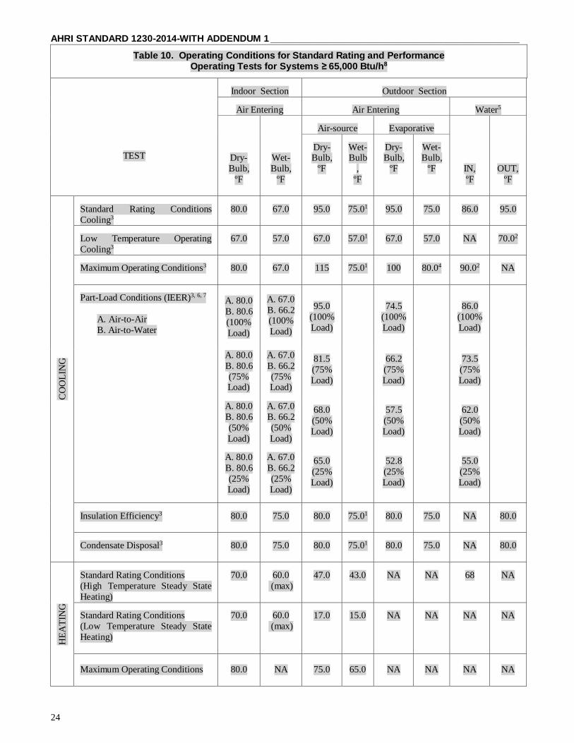
AHRI STANDARD 1230-2014-WITH ADDENDUM 1 ______________________________________________
24
Table 10. Operating Conditions for Standard Rating and Performance Operating Tests for Systems ≥ 65,000 Btu/h8
TEST
Indoor Section
Outdoor Section
Air Entering
Air Entering
Water5
Dry-
Bulb,
ºF
Wet-
Bulb,
ºF
Air-source
Evaporative
IN,
ºF
OUT,
ºF
Dry-Bulb,
ºF
Wet-Bulb
,
ºF
Dry-Bulb,
ºF
Wet-Bulb,
ºF
CO
OL
ING
Standard Rating Conditions
Cooling3
80.0
67.0
95.0
75.01
95.0
75.0
86.0
95.0
Low Temperature Operating
Cooling3
67.0
57.0
67.0
57.01
67.0
57.0
NA
70.02
Maximum Operating Conditions3
80.0
67.0
115
75.01
100
80.04
90.02
NA
Part-Load Conditions (IEER)3, 6, 7
A. Air-to-Air
B. Air-to-Water
A. 80.0
B. 80.6
(100%
Load)
A. 67.0
B. 66.2 (100%
Load)
95.0
(100%
Load)
74.5
(100%
Load)
86.0
(100%
Load)
A. 80.0
B. 80.6
(75% Load)
A. 67.0
B. 66.2
(75% Load)
81.5
(75%
Load)
66.2
(75%
Load)
73.5
(75%
Load)
A. 80.0
B. 80.6
(50%
Load)
A. 67.0
B. 66.2
(50%
Load)
68.0
(50%
Load)
57.5
(50%
Load)
62.0
(50%
Load)
A. 80.0
B. 80.6
(25%
Load)
A. 67.0
B. 66.2
(25%
Load)
65.0
(25%
Load)
52.8
(25%
Load)
55.0
(25%
Load)
Insulation Efficiency3
80.0
75.0
80.0
75.01
80.0
75.0
NA
80.0
Condensate Disposal3
80.0
75.0
80.0
75.01
80.0
75.0
NA
80.0
HE
AT
ING
Standard Rating Conditions
(High Temperature Steady State
Heating)
70.0
60.0
(max)
47.0
43.0
NA
NA
68
NA
Standard Rating Conditions
(Low Temperature Steady State
Heating)
70.0
60.0
(max)
17.0
15.0
NA
NA
NA
NA
Maximum Operating Conditions
80.0
NA
75.0
65.0
NA
NA
NA
NA

______________________________________________ AHRI STANDARD 1230-2014-WITH ADDENDUM 1
25
Table 10. Operating Conditions for Standard Rating and Performance Operating Tests for Systems ≥ 65,000 Btu/h8 (Continued)
Notes:
1. The wet-bulb temperature condition is not required when testing Air-source condensers which do not evaporate
condensate except for units with optional outdoor cooling coil.
2. Water flow rate as determined from Standard Rating Conditions Test.
3. Cooling rating and operating tests are not required for heating only Heat Pumps.
4. Make-up water temperature shall be 90.0ºF.
5. The ratings for water-source outdoor unit in this table apply only to air conditioning-only systems.
6. For part load rated indoor airflow, refer to Section 6.
7. For air-source, condenser airflow rate shall be adjusted per Section 6. For water-source, condenser water flow rate shall
be set at full load flow. 8. All tests shall be conducted at Stable Conditions.
6.4 Conditions for Standard Rating Tests for Heat Pump Systems that use Water-source for Heat Rejection.
6.4.1 Standard Ratings. Standard ratings shall be established at the standard rating conditions specified in 6.4.8 and
Tables 11 and 12. Standard ratings relating to cooling and heating capacities shall be net values, including the effects of
circulating- fan heat, but not including supplementary heat. Standard efficiency ratings shall be based on the effective
power input as defined in 3.6.
6.4.2 Power Input of Liquid Pumps.
6.4.2.1 If no liquid pump is provided with the Heat Pump, a pump power adjustment is to be included in the
effective power consumed by the Heat Pump, using the following formula:
φpa = q × Δp / η (14)
Where:
φpa = Pump power adjustment, in watts;
η = 1.59 (gpm)(ft H2O)(1/W) [0.3 × 10³ Liter/s*Pa*(1/W)] by convention;
Δp = Measured internal static pressure difference, (feet H2O)[pascals];
q = Nominal fluid flow rate, in gallons per minute [liters per second].
6.4.2.2 If a liquid pump is an integral part of the Heat Pump, only the portion of the pump power required to
overcome the internal resistance shall be included in the effective power input to the Heat Pump. The fraction
which is to be excluded from the total power consumed by the pump shall be calculated using the following
formula:
φpa = q × Δp / η (15)
Where:
φpa Pump power adjustment, in watts;
η = 1.59 (gpm)(ft H2O)(1/W) [0.3 × 10³] Liter/s*Pa*(1/W)] by convention; See note below.
Δp = The measured external static pressure difference, (feet H2O)[pascals];
q = Nominal fluid flow rate, in gallons per minute [liters per second].
Note: 0.3 ×10³ (L/s)(Pa)(1/W)
= 0.3 ×10³ (L/s)(Pa)(1/W)(15.850323 gpm/ (L/s)) (.000334552 ft H2O/ Pa) = 1.59 (gpm)(ft H2O)(1/W)
6.4.3 Liquid Flow Rates.
6.4.3.1 All standard ratings shall be determined at a liquid flow rate described below, expressed as gallons
per minute (liters per second).

AHRI STANDARD 1230-2014-WITH ADDENDUM 1 ______________________________________________
26
6.4.4 Heat pumps with integral liquid pumps shall be tested at the liquid flow rates specified by the manufacturer or
those obtained at zero external static pressure difference, whichever provides the lower liquid flow rate.
6.4.5 Heat pumps without integral liquid pumps shall be tested at the flow rates specified by the manufacturer.
6.4.6 The manufacturer shall specify a single liquid flow rate for all of the tests required in 6.4 unless automatic
adjustment of the liquid flow rate is provided by the equipment. A separate control signal output for each step of liquid
flow rate will be considered as an automatic adjustment. The manufacturer shall specify a single liquid flow rate for all of the tests required in Section 6.5 with a maximum limit of 5 gpm/ton. Automatic adjustment of the liquid flow rate
provided by the equipment shall be allowed. A separate control signal output for each step of liquid flow rate will be
considered as an automatic adjustment.
6.4.7 Test Liquids.
6.4.7.1 The test liquid for water-loop Heat Pumps and ground-water Heat Pumps shall be water.
6.4.7.2 The test liquid for ground-loop Heat Pumps shall be a 15% solution by mass of sodium chloride in
water.
6.4.7.3 The test liquid shall be sufficiently free of gas to ensure that the measured result is not influenced by
the presence of gas.
6.4.8 Standard Rating and Part-load Rating Test Conditions.
6.4.8.1 The test conditions for the determination of standard and part-load cooling ratings are specified in Table 11.
6.4.8.2 The test conditions for determination of standard and part-load heating ratings are specified in
Table 12.
6.4.8.3 Heat pumps intended for a specific application shall be rated at the conditions specified for that
application, for example, water-loop, ground-water, or ground-loop, and shall be identified as such (i.e., Water
Loop Heat Pump, Ground-water Heat pump, or Ground-loop Heat Pump). Heat pumps intended for two or
three applications shall be rated at the conditions specified for each of these applications and shall be so
identified (see 7.3 of ANSI/ARI/ASHRAE ISO Standard 13256-1:1998)
6.4.8.4 For each test, the equipment shall be operated continuously until equilibrium conditions are attained,
but for not less than one hour before capacity test data are recorded. The data shall then be recorded for
30 minutes at 5-minutes intervals until seven consecutive sets of readings have been attained within the
tolerances specified in 8.13.5. The averages of these data shall be used for the calculation of the test results.
Table 10. Test Conditions for The Determination of Cooling Capacity for Systems that use a Water Source for Heat Rejection
Water-loop
Heat Pumps
Ground-water
Heat Pumps
Ground-loop
Heat Pumps
Air entering indoor side
— dry bulb, °F [°C]
— wet bulb, °F [°C]
80.6 [27.0]
66.2 [19.0]
80.6 [27.0]
66.2 [19.0]
80.6 [27.0]
66.2 [19.0]
Air surrounding unit
— dry bulb, °F [°C]
80.6 [27.0]
80.6 [27.0]
80.6 [27.0]
Standard Rating Test Liquid entering heat exchanger, °F [°C]
86.0 [30.0]
59.0 [15.0]
77.0 [25.0]
Part Load Rating Test
Liquid entering heat exchanger, °F [°C]
86.0 [30.0]
59.0 [15.0]
68.0 [20.0]
Frequency1 Rated Rated Rated
Voltage2 Rated Rated Rated
Notes:
1) Equipment with dual-rated frequencies shall be tested at each frequency.
2) Equipment with dual-rated voltages shall be tested at both voltages, or at the lower if the two voltages if only a
single rating is published.

______________________________________________ AHRI STANDARD 1230-2014-WITH ADDENDUM 1
27
Table 11. Test Conditions for the Determination of Heating Capacity for Systems that use a Water Source for Heat Rejection
Water-loop
Heat Pumps
Ground-water
Heat Pumps
Ground-loop
Heat Pumps
Air entering indoor side1
— dry bulb, °F [°C]
— maximum wet bulb, °F [°C]
68.0 [20.0]
59.0 [15.0]
68.0 [20.0]
59.0 [15.0]
68.0 [20.0]
59.0 [15.0]
Air surrounding unit — dry bulb, °F [°C]
68.0 [20.0]
68.0 [20.0]
68.0 [20.0]
Standard Rating Test
Liquid entering heat exchanger, °F [°C]
68.0 [20.0]
50.0 [10.0]
32.0 [0]
Part Load Rating Test
Liquid entering heat exchanger, °F [°C]
68.0 [20.0]
50.0 [10.0]
41.0 [5.0]
Frequency1 Rated Rated Rated
Voltage2 Rated Rated Rated
Notes:
1) Equipment with dual-rated frequencies shall be tested at each frequency.
2) Equipment with dual-rated voltages shall be tested at both voltages, or at the lower if the two voltages if only a
single rating is published.
Table 11. Test Conditions for The Determination of Cooling Capacity for Systems that use a Water Source for Heat Rejection
Water-loop
Heat Pumps
Ground-water
Heat Pumps
Ground-loop
Heat Pumps
Air entering indoor side
— dry bulb, °F
— wet bulb, °F
80.6
66.2
80.6
66.2
80.6
66.2
Air surrounding outdoor unit
— dry bulb, °F
80.6
80.6
80.6
Standard Rating Test
Liquid entering heat exchanger, °F
86.0
59.0
77.0
Part Load Rating Test
Liquid entering heat exchanger, °F
See Table 10
59.0
68.0
Frequency1 Rated Rated Rated
Voltage2 Rated Rated Rated
Notes:
1. Equipment with dual-rated frequencies shall be tested at each frequency. 2. Equipment with dual-rated voltages shall be tested at both voltages, or at the lower if the two voltages if only a single
rating is published.

AHRI STANDARD 1230-2014-WITH ADDENDUM 1 ______________________________________________
28
Table 12. Test Conditions for the Determination of Heating Capacity for Systems that use a Water Source for Heat Rejection
Water-loop
Heat Pumps
Ground-water
Heat Pumps
Ground-loop
Heat Pumps
Air entering indoor side1
— dry bulb, °F
— maximum wet bulb, °F
68.0
59.0
68.0
59.0
68.0
59.0
Air surrounding outdoor unit — dry bulb, °F
68.0
68.0
68.0
Standard Rating Test
Liquid entering heat exchanger, °F
68.0
50.0
32.0
Part Load Rating Test
Liquid entering heat exchanger, °F NA NA
NA
Frequency1 Rated Rated Rated
Voltage2 Rated Rated Rated
Notes:
1. Equipment with dual-rated frequencies shall be tested at each frequency.
2. Equipment with dual-rated voltages shall be tested at both voltages, or at the lower if the two voltages if only a single
rating is published.
6.5 Part-Load Rating. Integrated Part-Load Value (IPLV) is in effect until January 1, 2010. See Appendix H for the method
and calculation of IPLV. Effective January 1, 2010, all units ≥ 65000 Btu/h [19,000W] rated in accordance with this standard
shall include an Integrated Energy Efficiency Ratio (IEER).
6.5.1 Part-load Rating Conditions. Test conditions for part-load ratings shall be per Table 9. Any water flow required
for system function shall be at water flow rates established at (full load) Standard Rating Conditions. Capacity reduction
means may be adjusted to obtain the specified step of unloading. No manual adjustment of indoor and outdoor airflow
rates from those of the Standard Rating Conditions shall be made. However, automatic adjustment of airflow rates by
system function is permissible.
6.5.2 General. The IEER is intended to be a measure of merit for the part-load performance of the unit. Each building may have different part-load performance due to local occupancy schedules, building construction, building
location and ventilation requirements. For specific building energy analysis an hour-by-hour analysis program should
be used.
6.5.3 Integrated Energy Efficiency Ratio (IEER). For equipment covered by this standard, the IEER shall be
calculated using test derived data and the following formula.
IEER = (0.020 · A) + (0.617 · B) + (0.238 · C) + (0.125 · D)
Where:
A = EER at 100% net capacity at AHRI standard rating conditions
B = EER at 75% net capacity and reduced ambient (see Table 12)
C = EER at 50% net capacity and reduced ambient (see Table 12)
D = EER at 25% net capacity and reduced ambient (see Table 12)
The IEER rating requires that the unit efficiency be determined at 100%, 75%, 50% and 25% load (net capacity) at the conditions specified in Table 12. If the unit, due to its capacity control logic cannot be operated at the 75%, 50%, or
25% load points, then the 75%, 50%, or 25% EER is determined by plotting the tested EER vs. the percent load and
using straight line segments to connect the actual performance points. Linear interpolation is used to determine the EER
at 75%, 50% and 25% net capacity. For the interpolation, an actual capacity point equal to or less than the required
rating point must be used to plot the curves. Extrapolation of the data is not allowed.
If the unit has a variable indoor airflow rate, the external static pressure shall remain constant at the full load rating point
as defined in Table 12, but the airflow rate should be adjusted to maintain the unit leaving dry bulb air temperature
measured at the full load rating point.
If the unit cannot be unloaded to the 75%, 50%, or 25% load then the unit should be run at the minimum step of unloading
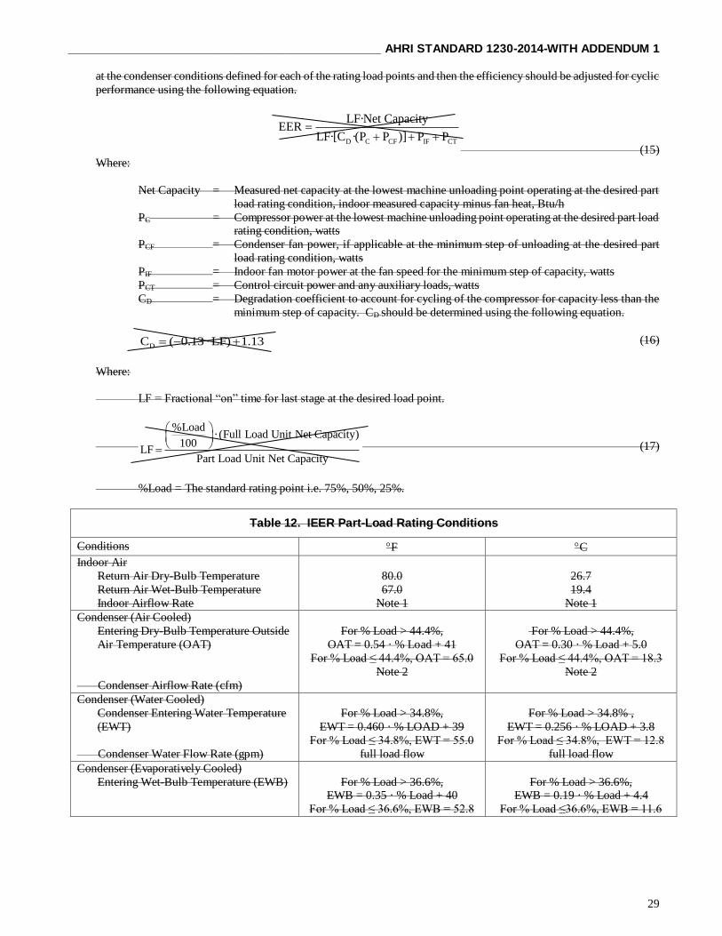
______________________________________________ AHRI STANDARD 1230-2014-WITH ADDENDUM 1
29
at the condenser conditions defined for each of the rating load points and then the efficiency should be adjusted for cyclic
performance using the following equation.
D C CF IF CT
LF·Net CapacityEER
LF·[C ·(P P )] P P
(15)
Where:
Net Capacity = Measured net capacity at the lowest machine unloading point operating at the desired part
load rating condition, indoor measured capacity minus fan heat, Btu/h
PC = Compressor power at the lowest machine unloading point operating at the desired part load rating condition, watts
PCF = Condenser fan power, if applicable at the minimum step of unloading at the desired part
load rating condition, watts
PIF = Indoor fan motor power at the fan speed for the minimum step of capacity, watts
PCT = Control circuit power and any auxiliary loads, watts
CD = Degradation coefficient to account for cycling of the compressor for capacity less than the
minimum step of capacity. CD should be determined using the following equation.
DC ( 0.13·LF) 1.13 (16)
Where:
LF = Fractional “on” time for last stage at the desired load point.
%Load·(Full Load Unit Net Capacity)
100LF
Part Load Unit Net Capacity
(17)
%Load = The standard rating point i.e. 75%, 50%, 25%.
Table 12. IEER Part-Load Rating Conditions
Conditions F C
Indoor Air
Return Air Dry-Bulb Temperature
Return Air Wet-Bulb Temperature
Indoor Airflow Rate
80.0
67.0
Note 1
26.7
19.4
Note 1
Condenser (Air Cooled)
Entering Dry-Bulb Temperature Outside
Air Temperature (OAT)
Condenser Airflow Rate (cfm)
For % Load > 44.4%,
OAT = 0.54 · % Load + 41
For % Load ≤ 44.4%, OAT = 65.0
Note 2
For % Load > 44.4%,
OAT = 0.30 · % Load + 5.0
For % Load ≤ 44.4%, OAT = 18.3
Note 2
Condenser (Water Cooled)
Condenser Entering Water Temperature
(EWT)
Condenser Water Flow Rate (gpm)
For % Load > 34.8%,
EWT = 0.460 · % LOAD + 39
For % Load ≤ 34.8%, EWT = 55.0
full load flow
For % Load > 34.8% ,
EWT = 0.256 · % LOAD + 3.8
For % Load ≤ 34.8%, EWT = 12.8
full load flow
Condenser (Evaporatively Cooled)
Entering Wet-Bulb Temperature (EWB)
For % Load > 36.6%, EWB = 0.35 · % Load + 40
For % Load ≤ 36.6%, EWB = 52.8
For % Load > 36.6%, EWB = 0.19 · % Load + 4.4
For % Load ≤36.6%, EWB = 11.6

AHRI STANDARD 1230-2014-WITH ADDENDUM 1 ______________________________________________
30
Table 12. IEER Part-Load Rating Conditions
Notes:
1 For fixed speed indoor fans the airflow rate should be held constant at the full load airflow rate. For units using discrete
step fan control, the fan speed should be adjusted as specified by the controls.
2 Condenser airflow should be adjusted as required by the unit controls for head pressure control.
6.5.4 Example Calculations.
Example 1 - Unit with proportional capacity control and can be run at the 75%, 50%, and 25% rating points and has a
fixed speed indoor fan.
Assume that the unit has the following measured capacity:
Using the measured performance you can then calculate the IEER as follows:
IEER (0.020 10.92) (0.617 11.13) (0.238 10.35) (0.125 7.39) 10.48
Example 2 – Unit has a single compressor with a fixed speed indoor fan.
Assume the unit has the following measured capacity:
Stage Ambient Actual % Load
Net Cap Cmpr (P C )
Cond (P CF )
Indoor (P IF )
Control (P CT )
EER
(°F) (Net Cap) Btu/h W W W W Btu/W 1 95.0 100 114,730 8,707 650 1,050 100 10.92 1 81.5 104.8 120,264 7,623 650 1,050 100 12.76 1 68.0 108.6 124,614 6,653 650 1,050 100 14.74 1 65.0 109.1 125,214 6,450 650 1,050 100 15.18
The unit cannot unload to the 75%, 50% or 25% points so tests were run with the compressor on at the ambient
temperatures specified for 75%, 50%, and 25%
Calculate the Load Factor (LF) and the CD factors and then calculate the adjusted performance for the 75%, 50%, and
25% points and then calculate the IEER.
Stage Ambient Actual %
Load
Net Cap Cmpr
(PC)
Cond
(PCF)
Indoor
(PIF)
Control
(PCT)
EER
(F) (Net Cap) Btu/h W W W W Btu/W
4 95.0 100 114,730 8,707 650 1,050 100 10.92
3 81.5 75 86,047 5,928 650 1,050 100 11.13
2 68.0 50 57,365 3,740 650 1,050 100 10.35
1 65.0 25 28,682 2,080 650 1,050 100 7.39

______________________________________________ AHRI STANDARD 1230-2014-WITH ADDENDUM 1
31
The following is an example of the CD calculation for the 50% point:
50·114,730
100LF .460
124,614
DC ( 0.13·.460) 1.13 1.070
50%
.460 124,614EER 12.08
.460 (1.070 (6,653 650)) 1,050 100
IEER=(0.020 10.92)+(0.617 11.81)+(0.238 12. 08)+(0.125 9.76)=11.60
Example 3 – Unit has two refrigeration circuits with one compressor in each circuit and two stages of capacity with a
fixed speed indoor fan.
Assume the unit has the following measured performance.
The unit can unload to get to the 75% point, but cannot unload to get to the 50% and 25% points so additional tests are
run at the 50% and 25% load ambients with the stage 1 loading.
Calculate the 50% and 25% load factors and DC factors as shown below.
Calculate the Load Factor (LF) and the DC factors and then calculate the adjusted performance for the 75%, 50%, and
25% points and then calculate the IEER:
IEER=(0.020 10.92)+(0.617 12.05)+(0.238 12. 60)+(0.125 10.04)=11.91
Example 4 – Unit has three refrigeration circuits with one compressor in each circuit and three stages of capacity with a
fixed speed indoor fan.
Assume the unit has the following measured performance.
Stage Ambient Actual %
Load
Net Cap Cmpr
(PC)
Cond
(PCF)
Indoor
(PIF)
Control
(PCT)
EER
(F) (Net Cap) Btu/h W W W W Btu/W
2 95.0 100 114,730 8,707 650 1,050 100 10.92
1 71.0 55.5 63,700 3,450 325 1,050 100 12.93
1 68.0 55.9 64,100 3,425 325 1,050 100 13.08
1 65.0 56.1 64,400 3,250 325 1,050 100 13.63
Stage Ambient Actual %
Load
Net Cap Cmpr
(PC)
Cond
(PCF)
Indoor
(PIF)
Control
(PCT)
EER CD LF
(F) (Net Cap) Btu/h W W W W Btu/W
2 95.0 100.0 114,730 8,707 650 1,050 100 10.92
1 71.0 55.5 63,700 3,450 325 1,050 100 12.93
75.0 12.05
1 68.0 55.9 64,100 3,425 325 1,050 100 13.08
50.0 Adjusted for Cyclic Performance 12.60 1.014 0.895
1 65.0 56.1 64,400 3,250 325 1,050 100 13.63
25.0 10.04 1.072 0.445
interpolation
Stage Ambient Actual %
Load
Net Cap Cmpr
(PC)
Cond
(PCF)
Indoor
(PIF)
Control
(PCT)
EER
(F) (Net Cap) Btu/h W W W W Btu/W
3 95.0 100.0 114,730 8,707 650 1,050 100 10.92
2 79.5 71.3 81,841 5,125 433 1,050 100 12.20
1 65.0 38.3 43,980 2,250 217 1,050 100 12.16

AHRI STANDARD 1230-2014-WITH ADDENDUM 1 ______________________________________________
32
The stage 1 operates at 38.3% capacity which is above the minimum 25% load point, but because the ambient condition
was 65 °F, another test at the 25% load ambient condition is not required as it would be the same test point.
Calculate the IEER which requires interpolation for the 75% and 50% point and the use of the degradation factor for the
25% point.
Stage Ambient Actual % Load
Net Cap Cmpr (PC)
Cond (PCF)
Indoor (PIF)
Control (PCT)
EER CD LF
(F) (Net Cap) Btu/h W W W W Btu/W NA NA
3 95.0 100.0 114,730 17,414 1,300 1,050 100 10.92 NA NA
2 79.5 71.3 81,841 4,950 433 1,050 100 12.53 NA NA
75.0 interpolation 12.32 NA NA
2 79.5 71.3 81,841 4,950 433 1,050 100 12.53 NA NA
1 65.0 38.3 43,980 2,250 217 1,050 100 12.16 NA NA
50.0 interpolation 12.57 NA NA
1 65.0 38.3 43,980 2,250 217 1,050 100 12.16 NA NA
25.0 Adjusted for Cyclic Performance 10.13 1.045 0.652
IEER = (0.02·10.92) + (0.617·12.32) + (0.238·12.57) + (0.125·10.13) = 12.08
Example 5 – Unit is a VAV unit and has 5 stages of capacity and a variable speed indoor.
Assume the unit has the following measured performance.
Stage Ambient Actual % Load
Net Cap Cmpr (PC)
Cond (PCF)
Indoor (PIF)
Control (PCT)
EER
(F) (Net Cap) Btu/h W W W W Btu/W
5 95.0 100.0 229,459 17,414 1,300 2,100 200 10.92
4 85.1 81.7 187,459 11,444 1,300 1,229 150 13.27
3 74.0 61.0 140,064 6,350 1,300 575 150 16.72
2 69.6 52.9 121,366 6,762 650 374 150 15.29
1 65.0 30.6 70,214 2,139 650 85 150 23.2
This unit can unload down to 30.6% so a degradation calculation will be required but because the stage 1 was already
run at the lowest ambient and the ambient for the 25% load point no additional tests are required.
Using this data you can then calculate the standard load points.
Note: Blank space equals NA.
Stage Ambient Actual %
Load
Net Cap Cmpr
(PC)
Cond
(PCF)
Indoor
(PIF)
Control
(PCT)
EER CD LF
(F) (Net Cap) Btu/h W W W W Btu/W
5 95.0 100.0 229,459 17,414 1,300 2,100 200 10.92
4 85.1 81.7 187,459 11,444 1,300 1,229 150 13.27
3 74.0 61.0 140,064 6,350 1,300 575 150 16.72
75.0 14.39
2 69.6 52.9 121,366 6,762 650 374 150 15.29
1 65.0 30.6 70,214 2,139 650 85 150 23.22
50.0 16.32
25.0 Adjusted for Cyclic Performance 22.34 1.024 0.817
interpolation
interpolation
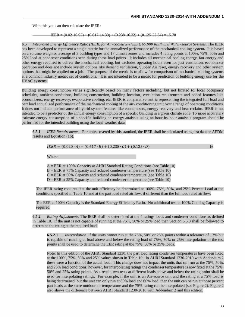
______________________________________________ AHRI STANDARD 1230-2014-WITH ADDENDUM 1
33
With this you can then calculate the IEER:
IEER = (0.02·10.92) + (0.617·14.39) + (0.238·16.32) + (0.125·22.34) = 15.78
6.5 Integrated Energy Efficiency Ratio (IEER) for Air-cooled Systems ≥ 65,000 Btu/h and Water-source Systems. The IEER
has been developed to represent a single metric for the annualized performance of the mechanical cooling system. It is based
on a volume weighted average of 3 building types and 17 climate zones and includes 4 rating points at 100%, 75%, 50% and 25% load at condenser conditions seen during these load points. It includes all mechanical cooling energy, fan energy and
other energy required to deliver the mechanical cooling, but excludes operating hours seen for just ventilation, economizer
operation and does not include system options like demand ventilation, Supply Air reset, energy recovery and other system
options that might be applied on a job. The purpose of the metric is to allow for comparison of mechanical cooling systems
at a common industry metric set of conditions. It is not intended to be a metric for prediction of building energy use for the
HVAC systems.
Building energy consumption varies significantly based on many factors including, but not limited to, local occupancy
schedules, ambient conditions, building construction, building location, ventilation requirements and added features like
economizers, energy recovery, evaporative cooling, etc. IEER is comparative metric representing the integrated full load and
part load annualized performance of the mechanical cooling of the air- conditioning unit over a range of operating conditions.
It does not include performance of hybrid system features like economizers, energy recovery and heat reclaim. IEER is not
intended to be a predictor of the annual energy consumption of a specific building in a given climate zone. To more accurately
estimate energy consumption of a specific building an energy analysis using an hour-by-hour analysis program should be
performed for the intended building using the local weather data.
6.5.1 IEER Requirements. For units covered by this standard, the IEER shall be calculated using test data or AEDM results and Equation (16).
𝐼𝐸𝐸𝑅 = (0.020 ∙ 𝐴) + (0.617 ∙ 𝐵) + (0.238 ∙ 𝐶) + (0.125 ∙ 𝐷) 16
Where:
A = EER at 100% Capacity at AHRI Standard Rating Conditions (see Table 10) B = EER at 75% Capacity and reduced condenser temperature (see Table 10)
C = EER at 50% Capacity and reduced condenser temperature (see Table 10)
D = EER at 25% Capacity and reduced condenser temperature (see Table 10)
The IEER rating requires that the unit efficiency be determined at 100%, 75%, 50%, and 25% Percent Load at the
conditions specified in Table 10 and at the part load rated airflow, if different than the full load rated airflow.
The EER at 100% Capacity is the Standard Energy Efficiency Ratio. No additional test at 100% Cooling Capacity is
required.
6.5.2 Rating Adjustments. The IEER shall be determined at the 4 ratings loads and condenser conditions as defined
in Table 10. If the unit is not capable of running at the 75%, 50% or 25% load then Section 6.5.3 shall be followed to
determine the rating at the required load.
6.5.2.1 Interpolation. If the units cannot run at the 75%, 50% or 25% points within a tolerance of ±3% but
is capable of running at load above and below the rating load of 75%, 50% or 25% interpolation of the test
points shall be used to determine the EER rating at the 75%, 50% or 25% loads.
Note: In this edition of the AHRI Standard 1230, the part load rating condenser temperatures have been fixed
at the 100%, 75%, 50% and 25% values shown in Table 10. In AHRI Standard 1230-2010 with Addendum 2
these were a function of the actual load. This change does not impact the units that can run at the 75%, 50%,
and 25% load conditions; however, for interpolating ratings the condenser temperature is now fixed at the 75%,
50% and 25% rating points. As a result, two tests at different loads above and below the rating point shall be
used for interpolating ratings. For example, if the unit is an Air-source unit and the rating at a 75% load is
being determined, but the unit can only run at 80% load and 60% load, then the unit can be run at those percent
part loads at the same outdoor air temperature and the 75% rating can be interpolated (see Figure 2). Figure 2
also shows the difference between AHRI Standard 1230-2010 with Addendum 2 and this edition.

AHRI STANDARD 1230-2014-WITH ADDENDUM 1 ______________________________________________
34
Figure 2. Example Revised Part Load Ambient Conditions for Interpolation
6.5.2.2 Degradation. If the unit cannot be unloaded to the 75%, 50%, or 25% load then the unit shall be run
at the minimum step of unloading and minimum rated indoor airflow at the condenser conditions defined for
each of the rating Percent Load IEER points listed in Table 10 and then the part load EER shall be adjusted for
cyclic performance using Equation 17.
𝐸𝐸𝑅 =𝐿𝐹
𝐿𝐹×[𝐶𝐷×(𝑃𝐶+𝑃𝐶𝐷)]+𝑃𝐶𝑇 17
Where:
CD = The degradation coefficient to account for cycling of the compressor for capacity less than
the minimum step of capacity. CD shall be determined using Equation 18.
PC = Compressor power at the lowest machine unloading point operating at the desired part load
rating condition, watts
PCD = Condenser Section power, if applicable at the desired part load rating condition, watts. For
Air-source and evaporatively cooled units this power is the power of the fans and pumps.
PCT = Control circuit power and any auxiliary loads, watts
𝐶𝐷 = (−0.13 ∙ 𝐿𝐹) + 1.13 18
Where:
LF = Fractional “on” time for last stage at the desired load point, noted in Equation 19.
𝐿𝐹 =(𝑃𝑒𝑟𝑐𝑒𝑛𝑡 𝐿𝑜𝑎𝑑
100⁄ ) ∙𝐹𝑢𝑙𝑙 𝐿𝑜𝑎𝑑 𝑁𝑒𝑡 𝐶𝑎𝑝𝑎𝑐𝑖𝑡𝑦
𝑃𝑎𝑟𝑡 𝐿𝑜𝑎𝑑 𝑁𝑒𝑡 𝐶𝑎𝑝𝑎𝑐𝑖𝑡𝑦 19
6.5.3 Procedure for Calculating IEER. The IEER shall be calculated using data and the following procedures.
For test purposes, test units shall be provided with manual means to adjust the unit refrigeration capacity in steps no greater than 5% of the full load Rated Capacity by adjusting variable capacity compressor(s) capacity and or the stages
of refrigeration capacity.
70
72
74
76
78
80
82
84
86
88
90
55% 60% 65% 70% 75% 80% 85%
Air
-so
urc
e O
utd
oo
r A
ir T
em
per
atu
re (F
)
% Load
AHRI 1230-2010 AHRI 1230-2016 Rating Point B (75%)

______________________________________________ AHRI STANDARD 1230-2014-WITH ADDENDUM 1
35
6.5.3.1 The following sequential steps shall be followed.
6.5.3.1.1 For part load rating tests, the unit shall be configured per the manufacturer’s
instructions, including setting of stages of refrigeration and variable capacity compressor loading
percent for each of the part load rating points. The stages of refrigeration and variable capacity
compressor loading percent that result in capacity closest to the desired part load rating point of
75%, 50%, or 25%.
6.5.3.1.2 The condenser entering temperature shall be adjusted per the requirements of Table
11 and be within tolerance as defined in ASHRAE Standard 37 Table 2b.
6.5.3.1.3 The indoor airflow and static shall be adjusted per Section 6.
6.5.3.1.4 If the measured part load rating capacity ratio is within ±3%, based on the full load measured test Cooling Capacity, above or below the part load capacity point, the EER at each load
point shall be used to determine IEER without any interpolation.
6.5.3.1.5 If the unit, due to its capacity control logic cannot be operated at the 75%, 50%, or
25% Percent Load within 3%, then an additional rating point(s) is required and the 75%, 50%, or
25% EER is determined by using linear interpolation. Extrapolation of the data is not allowed.
6.5.3.2 The additional test point(s) for interpolations shall be run as follows:
6.5.3.2.1 The ambient test conditions shall be within tolerances defined in ASHRAE Standard
37 of the specified ambient in Table 7 based on the IEER rating point of 75%, 50% or 25%.
Note: The condenser temperature shall be fixed for the two interpolation rating points at the values
listed in Table 10.
6.5.3.2.2 The indoor airflow shall be set as specified by the manufacturer and as required by
Section 6.
6.5.3.2.3 The stages of refrigeration capacity shall be increased or decreased within the limit of
the controls and until the measured part load is closest to the IEER percent part load rating point is
obtained.
Note: For example, to obtain a 50% rating point for a unit having test points at both 60% and 70%,
the 60% test point shall be used.
6.5.3.2.4 The measured part load capacity of the second test point shall be less than the part load
rating capacity point if the measured capacity of the first test is greater than the part load capacity
point.
6.5.3.2.5 The measured part load capacity of the second test point shall be more than the part
load capacity point if the measured capacity of the first test is less than the part load capacity point.
6.5.4 Part Load External Static and Airflow. For part load testing the following procedure shall be used for indoor
airflow and static.
6.5.4.1 Fixed Speed Indoor Fan Control. For fixed speed indoor fans the airflow rate shall be held constant
at the Full Load Rated Indoor Airflow ±3%. Otherwise, airflow may be adjusted as automatically performed
by the unit controls.
6.6 Verification Testing Uncertainty. When verifying the ratings by testing a sample unit, there are uncertainties that must
be considered. Verification tests, including tests conducted for the AHRI certification program shall be conducted in a
laboratory that meets the requirements referenced in this standard and ASHRAE Standard 37 and must demonstrate
performance with an allowance for uncertainty. The following make up the uncertainty for products covered by this standard.
6.6.1 Uncertainty of Measurement. When testing a unit, there are variations that result from instrumentation and

AHRI STANDARD 1230-2014-WITH ADDENDUM 1 ______________________________________________
36
measurements of temperatures, pressure, and flow rates.
6.6.2 Uncertainty of Test Rooms. A unit tested in multiple rooms will not yield the same performance due to setup
variations.
6.6.3 Variation due to Manufacturing. During the manufacturing of units, there are variations due to manufacturing
production tolerances that will impact the performance of a unit.
6.6.4 Uncertainty of Performance Simulation Tools. Due to the large complexity of options, use of performance
prediction tools like an AEDM has some uncertainties.
6.7 To comply with this standard, verification tests shall meet the performance metrics shown in Table 13 with an uncertainty
allowance not greater than the following:
Table 13. Uncertainty Allowances
Performance Metric Uncertainty
Allowance
Acceptance
Criteria1
Cooling Capacity 5% ≥ 95%
SEER2 5% ≥ 95%
EER 5% ≥ 95%
IEER3 10% ≥ 90%
SCHE4 10% ≥ 90%
Heating Capacity5 5% ≥ 95%
COP3,5 5% ≥ 95%
HSPF2 5% ≥ 95%
Notes:
1) Must be ≥ (1 – uncertainty allowance).
2) Applies only to systems < 65,000 Btu/h [19,000 W]
3) Applies only to systems ≥ 65,000 Btu/h [19,000 W]
4)Applies to heat recovery systems only
5) Includes the high temperature and low temperature conditions, and the
temperature condition for water-source systems
Section 7. Minimum Data Requirements for Published Ratings
7.1 Minimum Data Requirements for Published Ratings. As a minimum, Published Ratings shall consist of the following
information:
a. For VRF Multi-Split Air-Conditioners <65,000 Btu/h [19,000 W]
1. Standard Rating Cooling Capacity Btu/h [W]
2. Seasonal Energy Efficiency Ratio, SEER Btu/(Wh)
b. For VRF Multi-Split Air-Conditioners ≥ 65,000 Btu/h [19,000 W]
1. Standard Rating Cooling Capacity Btu/h [W]
2. Energy Efficiency Ratio, EER Btu/(Wh) 3. Integrated Energy Efficiency Ratio, IEER (Integrated Part-Load Value, IPLV is Superseded by IEER January 1,
2010)
c. For all VRF Multi-Split Heat Pumps <65,000 Btu/h [19,000 W]
1. Standard Rating Cooling Capacity Btu/h [W]
2. Seasonal Energy Efficiency Ratio, SEER Btu/(Wh)
3. High Temperature Heating Standard Rating Capacity Btu/(Wh) [W]
4. Region IV Heating Seasonal Performance Factor, HSPF, minimum design heating requirement (Wh)
d. For VRF Multi-Split Heat Pumps ≥ 65,000 Btu/h [19,000 W]
1. Standard Rating Cooling Capacity Btu/h [W]
2. Energy Efficiency Ratio, EER Btu/(Wh)
______________________________________________ AHRI STANDARD 1230-2014-WITH ADDENDUM 1
37
3. Integrated Energy Efficiency Ratio, IEER (Integrated Part-Load Value, IPLV is Superseded by IEER January 1,
2010)
4. High Temperature Heating Standard Rating Capacity Btu/h [W]
5. High Temperature Coefficient of Performance
6. Low Temperature Heating Standard Rating Capacity Btu/h [W]
7. Low Temperature Coefficient of Performance
e. For VRF Multi-Split Heat Recovery Heat Pumps
1. Ratings Appropriate in 7 (c) (d) above
2. Simultaneous Cooling and Heating Efficiency (SCHE) (50% heating/50% cooling)
f. For VRF Multi-Split Heat Pumps Systems that Use a Water Source for Heat Rejection
1. Standard Rating Cooling Capacity Btu/h [W]
2. Energy Efficiency Ratio, EER Btu/(Wh) 3. Integrated Energy Efficiency Ratio, IEER (Integrated Part-Load Value, IPLV is Superseded by IEER January
1, 2010)
4. Heating Standard Rating Capacity Btu/h [W]
5. Heating Coefficient of Performance
6. Simultaneous Cooling and Heating Efficiency (SCHE) (50% heating/50% cooling)/ (Heat Recovery models
only)
7.2 Latent Cooling Capacity Designation. The moisture removal designation shall be published in the manufacturer’s
specifications and literature. The value shall be expressed consistently in either gross or net in one or more of the following
forms:
a. Sensible cooling capacity/total cooling capacity ratio (sensible heat ratio) and total capacity, Btu/h [W] b. Latent cooling capacity and total cooling capacity, Btu/h [W]
c. Sensible cooling capacity and total cooling capacity, Btu/h [W]
7.3 Rating Claims. All claims to ratings within the scope of this standard shall include the statement “Rated in accordance
with AHRI Standard 1230”. All claims to ratings outside the scope of this standard shall include the statement: “Outside the
scope of AHRI Standard 1230”. Wherever Application Ratings are published or printed, they shall include a statement of the
conditions at which the ratings apply.
Section 8. Operating Requirements
8.1 Operating Requirements. Unitary equipment shall comply with the provisions of this section such that any production
unit will meet the requirements detailed herein.
8.2 Operating Requirements for Systems < 65,000 Btu/h [19,000 W].
8.2.1 Maximum Operating Conditions Test for Systems < 65,000 Btu/h [19,000 W]. Unitary equipment shall pass the following maximum operating conditions test with an indoor-coil airflow rate as determined under 6.1.5.1.
8.2.1.1 Temperature Conditions. Temperature conditions shall be maintained as shown in Table 8.
8.2.2 Voltages. The test shall be run at the Range A minimum utilization voltage from AHRI Standard 110, Table 1,
based upon the unit's nameplate rated voltage(s). This voltage shall be supplied at the unit's service connection and at
rated frequency.
8.2.3 Procedure. The equipment shall be operated for one hour at the temperature conditions and voltage specified.
8.2.4 Requirements. The equipment shall operate continuously without interruption for any reason for one hour.
8.2.4.1 Units with water-cooled condensers shall be capable of operation under these maximum conditions at
a water pressure drop not to exceed 413.5 in H2O [103 kPa], measured across the unit.
8.3 Voltage Tolerance Test for Systems < 65,000 Btu/h [19,000 W]. Unitary equipment shall pass the following voltage
tolerance test with a cooling coil airflow rate as determined under 6.1.5.1.

AHRI STANDARD 1230-2014-WITH ADDENDUM 1 ______________________________________________
38
8.3.1 Temperature Conditions. Temperature conditions shall be maintained at the standard cooling (and/or standard
heating, as required) steady state conditions as shown in Table 8.
8.3.2 Voltages.
8.3.2.1 Tests shall be run at the Range B minimum and maximum utilization voltages from ARI Standard
110, Table 1, based upon the unit's nameplate rated voltage(s). These voltages shall be supplied at the unit's service connection and at rated frequency. A lower minimum or a higher maximum voltage shall be used, if
listed on the nameplate.
8.3.2.2 The power supplied to single phase equipment shall be adjusted just prior to the shut-down period
(8.3.3.2) so that the resulting voltage at the unit's service connection is 86% of nameplate rated voltage when
the compressor motor is on locked-rotor. (For 200V or 208V nameplate rated equipment the restart voltage
shall be set at 180V when the compressor motor is on locked rotor). Open circuit voltage for three-phase
equipment shall not be greater than 90% of nameplate rated voltage.
8.3.2.3 Within one minute after the equipment has resumed continuous operation (8.3.4.3), the voltage shall
be restored to the values specified in 8.3.2.1.
8.3.3 Procedure.
8.3.3.1 The equipment shall be operated for one hour at the temperature conditions and voltage(s) specified.
8.3.3.2 All power to the equipment shall be interrupted for a period sufficient to cause the compressor to stop (not to exceed five seconds) and then restored.
8.3.4 Requirements.
8.3.4.1 During both tests, the equipment shall operate without failure of any of its parts.
8.3.4.2 The equipment shall operate continuously without interruption for any reason for the one hour period
preceding the power interruption.
8.3.4.3 The unit shall resume continuous operation within two hours of restoration of power and shall then
operate continuously for one-half hour. Operation and resetting of safety devices prior to establishment of
continuous operation is permitted.
8.4 Low-Temperature Operation Test for Systems < 65,000 Btu/h [19,000 W] (Cooling). Unitary equipment shall pass the
following low-temperature operation test when operating with initial airflow rates as determined in 6.1.5.1 and 6.1.6 and with
controls and dampers set to produce the maximum tendency to frost or ice the evaporator, provided such settings are not
contrary to the manufacturer's instructions to the user.
8.4.1 Temperature Conditions. Temperature Conditions shall be maintained as shown in Table 8.
8.4.2 Procedure. The test shall be continuous with the unit on the cooling cycle, for not less than four hours after
establishment of the specified temperature conditions. The unit will be permitted to start and stop under control of an
automatic limit device, if provided.
8.4.3 Requirements.
8.4.3.1 During the entire test, the equipment shall operate without damage or failure of any of its parts.
8.4.3.2 During the entire test, the air quantity shall not drop more than 25% from that determined under the
Standard Rating Test.
8.4.3.3 During the test and during the defrosting period after the completion of the test, all ice or meltage must
be caught and removed by the drain provisions.
8.5 Insulation Effectiveness Test (Cooling). Test for Systems < 65,000 Btu/h [19,000 W]. Unitary equipment shall pass the following insulation effectiveness (aka insulation efficiency test) when operating with airflow rates as determined in 6.1.5.1

______________________________________________ AHRI STANDARD 1230-2014-WITH ADDENDUM 1
39
and 6.1.6 with controls, fans, dampers, and grilles set to produce the maximum tendency to sweat, provided such settings are
not contrary to the manufacturer's instructions to the user.
8.5.1 Temperature Conditions. Temperature conditions shall be maintained as shown in Table 8.
8.5.2 Procedure. After establishment of the specified temperature conditions, the unit shall be operated continuously
for a period of four hours.
8.5.3 Requirements. During the test, no condensed water shall drop, run, or blow off from the unit casing.
8.6 Condensate Disposal Test (Cooling). Test for Systems < 65,000 Btu/h [19,000 W]. Unitary equipment which rejects
condensate to the condenser air shall pass the following condensate disposal test when operating with airflow rates as
determined in 6.1.5.1 and 6.1.6 and with controls and dampers set to produce condensate at the maximum rate, provided such
settings are not contrary to the manufacturer's instructions to the user. (This test may be run concurrently with the Insulation
Effectiveness Test (8.5)).
8.6.1 Temperature Conditions. Temperature conditions shall be maintained as shown in Table 8.
8.6.2 Procedure. After establishment of the specified temperature conditions, the equipment shall be started with its
condensate collection pan filled to the overflowing point and shall be operated continuously for four hours after the
condensate level has reached equilibrium.
8.6.3 Requirements. During the test, there shall be no dripping, running-off, or blowing-off of moisture from the unit
casing.
8.7 Test Tolerance for Systems <65,000 Btu/h [19,000 W]. The conditions for the tests outlined in Section 8 are average
values subject to tolerances of ± 1.0°F [± 0.6°C] for air wet-bulb and dry-bulb temperatures and ± 1.0% of the reading for
voltages.
8.8 Operating Requirements for Systems ≥ 65,000 Btu/h [19,000 W].
8.8.1 Maximum Operating Conditions Test (Cooling and Heating) Systems ≥ 65,000 Btu/h [19,000 W]. Multi-Split
Air-Conditioners and Heat Pumps shall pass the following maximum cooling and heating operating conditions test with
an indoor coil airflow rate as determined under 6.3.1 (refer to test for equipment with optional air cooling coils in Section
6.3.3).
8.8.2 Temperature Conditions. Temperature conditions shall be maintained as shown in Table 10.
8.8.3 Voltages. Tests shall be run at the minimum and maximum utilization voltages of Voltage Range B as shown
in Table 1 of AHRI Standard 110, at the unit's service connection and at rated frequency.
8.8.4 Procedure.
8.8.4.1 Multi-split Air-Conditioners and Heat Pumps shall be operated continuously for one hour at the
temperature conditions and voltage(s) specified.
8.8.4.2 All power to the unitary equipment shall be interrupted for a period sufficient to cause the compressor
to stop (not to exceed five seconds) and then be restored.
8.8.5 Requirements.
8.8.5.1 During both tests, the unitary equipment shall operate without failure of any of its parts.
8.8.5.2 The unit shall resume continuous operation within one hour of restoration of power and shall then
operate continuously for one hour. Operation and resetting of safety devices prior to establishment of
continuous operation is permitted.
8.8.5.3 Units with water-cooled condensers shall be capable of operation under these maximum conditions at
a water-pressure drop not to exceed 413.5 in H2O [103 kPa] measured across the unit.

AHRI STANDARD 1230-2014-WITH ADDENDUM 1 ______________________________________________
40
8.8.6 Maximum Operating Conditions Test for Equipment with Optional Outdoor Cooling Coil. Multi-split Air
Conditioners and Heat Pumps which incorporate an outdoor air cooling coil shall use the conditions, voltages, and
procedure (Sections 8.8.1 through 8.8.4) and meet the requirements of 8.8.5 except for the following changes.
a. Outdoor air set as in Section 6.3.1
b. Return air temperature conditions shall be 80.0ºF [26.7ºC] dry-bulb, 67.0ºF [19.4ºC] wet-bulb
c. Outdoor air entering outdoor air cooling coil shall be 115ºF [46.1ºC] dry-bulb and 75.0ºF [23.9ºC] wet-bulb
8.9 Cooling Low Temperature Operation Test for Systems ≥ 65,000 Btu/h [19,000 W]. Multi-split Air-Conditioners and
Heat Pumps shall pass the following low-temperature operation test when operating with initial airflow rates as determined in
Sections 6.3.1, 6.3.4, and with controls and dampers set to produce the maximum tendency to frost or ice the indoor coil,
provided such settings are not contrary to the manufacturer's instructions to the user.
8.9.1 Temperature Conditions. Temperature conditions shall be maintained as shown in Table 10.
8.9.2 Voltage and Frequency. The test shall be performed at nameplate rated voltage and frequency.
For air-conditioners and Heat Pumps with dual nameplate voltage ratings, tests shall be performed at the lower of the
two voltages.
8.9.3 Procedure. The test shall be continuous with the unit in the cooling cycle for not less than four hours after
establishment of the specified temperature conditions. The unit will be permitted to start and stop under control of an
automatic limit device, if provided.
8.9.4 Requirements.
8.9.4.1 During the entire test, the unitary equipment shall operate without damage to the equipment.
8.9.4.2 During the entire test, the indoor airflow rate shall not drop more than 25% from that specified for the
Standard Rating Test.
8.9.4.3 During all phases of the test and during the defrosting period after the completion of the test, all ice or
meltage must be caught and removed by the drain provisions.
8.10 Insulation Efficiency Test (Cooling) for Systems ≥ 65,000 Btu/h [19,000 W]. Multi-Split Air-Conditioners and Heat
Pumps shall pass the following Insulation Efficiency Test when operating with airflow rates as determined in 6.3.1, 6.3.4, and
with controls, fans, dampers, and grilles set to produce the maximum tendency to sweat, provided such settings are not contrary
to the manufacturer's instructions to the user.
8.10.1 Temperature Conditions. Temperature conditions shall be maintained as shown in Table 10.
8.10.2 Procedure. After establishment of the specified temperature conditions, the unit shall be operated continuously
for a period of four hours.
8.10.3 Requirements. During the test, no condensed water shall drop, run, or blow off from the unit casing.
8.11 Condensate Disposal Test (Cooling) for Systems ≥ 65,000 Btu/h [19,000 W]. Multi-Split Air-Conditioners and Heat
Pumps which reject condensate to the condenser air shall pass the following condensate disposal test when operating with
airflow rates as determined in Sections 6.3.1, 6.3.4, and with controls and dampers set to produce condensate at the maximum
rate, provided such settings are not contrary to the manufacturer's instructions to the user (This test may be run concurrently
with the insulation efficiency test (Section 8.10)).
8.11.1 Temperature Conditions. Temperature conditions shall be maintained as shown in Table 10.
8.11.2 Procedure. After establishment of the specified temperature conditions, the equipment shall be started with its
condensate collection pan filled to the overflowing point and shall be operated continuously for four hours after the
condensate level has reached equilibrium.

______________________________________________ AHRI STANDARD 1230-2014-WITH ADDENDUM 1
41
8.11.3 Requirements. During the test, there shall be no dripping, running-off, or blowing-off of moisture from the unit
casing.
8.12 Tolerances for Systems ≥ 65,000 Btu/h [19,000 W]. The conditions for the tests outlined in Sections 8.2 and 8.3 are
average values subject to tolerances of ±1.0ºF [±0.6ºC] for air wet-bulb and dry-bulb temperatures, ±0.5ºF [±0.3ºC] for
water temperatures, and ±1.0% of the readings for specified voltage.
8.13 Performance Requirements for Systems using a Water Source for Heat Rejection.
8.13.1 Capacity Requirements.
8.13.1.1 To be consistent with ISO 13256-1-2, water-to-air and brine-to-air heat pumps shall be designed and
produced such that any production unit will meet the applicable requirements of this standard.
8.13.1.2 For Heat Pumps with capacity control, the performance requirements tests shall be conducted at
maximum capacity.
8.13.2 Maximum Operating Conditions Test.
8.13.2.1 Test conditions. The maximum operating conditions tests shall be conducted for cooling and heating
at the test conditions established for the specific applications specified in Tables 14 and 15. Heat pumps
intended for use in two or more applications shall be tested at the most stringent set of conditions specified in
Tables 14 and 15.
8.13.2.2 Test Procedures.
8.13.2.2.1 The equipment shall be operated continuously for one hour after the specified temperatures
have been established at each specified voltage level.
8.13.2.2.2 The 110% voltage test shall be conducted prior to the 90% voltage test.
8.13.2.2.3 All power to the equipment shall be interrupted for three minutes at the conclusion of the
one hour test at the 90% voltage level and then restored for one hour.
8.13.2.3 Test Requirements. Heat pumps shall meet the following requirements when operating at the
conditions specified in Tables 14 and 15.
8.13.2.3.1 During the entire test, the equipment shall operate without any indication of damage.
8.13.2.3.2 During the test period specified in Section 8.13.2.2.1, the equipment shall operate
continuously without tripping any motor overload or other protective devices.
8.13.2.3.3 During the test period specified in Section 8.13.2.2.3, the motor overload protective device
may trip only during the first five minutes of operation after the shutdown period of three minutes.
During the remainder of the test period, no motor overload protective device shall trip. For those
models so designed that resumption of operation does not occur within the first five minutes after the
initial trip, the equipment may remain out of operation for no longer than 30 minutes. It shall then
operate continuously for the remainder of the test period.

AHRI STANDARD 1230-2014-WITH ADDENDUM 1 ______________________________________________
42
Table 14. Maximum Cooling Test Conditions for Systems that use a Water Source for Heat Rejection
Water-loop
Heat Pumps Ground-water
Heat Pumps Ground-loop
Heat Pumps Air entering indoor side1
— dry bulb
— wet bulb
°F °C °F °C °F °C
89.6
73.4
32.0
23.0
89.6
73.4
32.0
23.0
89.6
73.4
32.0
23.0
Air surrounding unit
— dry bulb
89.6
32.0
89.6
32.0
89.6
32.0
Liquid entering heat exchanger1
104
40.0
77.0
25.0
104
40.0
Frequency2 Rated Rated Rated
Voltage 1) 90% and 110% of
rated voltage for
equipment with a
single nameplate
rating.
2) 90% of minimum
voltage and 110% of maximum voltage for
equipment with dual
nameplate voltage.
1) 90% and 110% of
rated voltage for
equipment with a
single nameplate
rating.
2) 90% of minimum
voltage and 110% of maximum voltage for
equipment with dual
nameplate voltage.
1) 90% and 110% of rated
voltage for equipment
with a single nameplate
rating.
2) 90% of minimum
voltage and 110% of
maximum voltage for equipment with dual
nameplate voltage.
Notes:
1) Air and liquid flow rates shall be as established in Sections 6.1.5 and 6.4.3.
2) Equipment with dual-rated frequencies shall be tested at each frequency.
Table 15. Maximum Heating Test Conditions for Systems that use a Water Source for Heat Rejection
Water-loop
Heat Pumps Ground-water
Heat Pumps Ground-loop
Heat Pumps
Air entering indoor side1
— dry bulb
°F °C °F °C °F °C
80.6 27.0 80.6 27.0 80.6 27.0
Air surrounding unit
— dry bulb
80.6
27.0
80.6
27.0
80.6
27.0
Liquid entering heat exchanger1 86.0 30.0 77.0 25.0 77.0 25.0
Frequency2 Rated Rated Rated
Voltage 1) 90% and 110% of
rated voltage for
equipment with a single nameplate
rating.
2) 90% of minimum
voltage and 110% of
maximum voltage for
equipment with dual
nameplate voltage.
1) 90% and 110% of
rated voltage for
equipment with a single nameplate
rating.
2) 90% of minimum
voltage and 110% of
maximum voltage for
equipment with dual
nameplate voltage.
1) 90% and 110% of rated
voltage for equipment
with a single nameplate rating.
2) 90% of minimum
voltage and 110% of
maximum voltage for
equipment with dual
nameplate voltage.
Notes:
1) Air and liquid flow rates shall be as established in 6.1.5 and 6.4.3. 2) Equipment with dual-rated frequencies shall be tested at each frequency.
8.13.3 Minimum Operating Conditions Test. Heat pumps shall be tested at the minimum operating test conditions for
cooling and heating at the test conditions established for the specific applications specified in Tables 16 and 17. Heat
pumps intended for use in two or more applications shall be tested at the most stringent set of conditions specified in Tables 16 and 17.

______________________________________________ AHRI STANDARD 1230-2014-WITH ADDENDUM 1
43
8.13.3.1 Test Procedures. For the minimum operating cooling test, the Heat Pump shall be operated
continuously for a period of no less than 30 minutes after the specified temperature conditions have been
established. For the minimum operating heating test, the Heat Pump shall soak for 10 minutes with liquid at
the specified temperature circulating through the coil. The equipment shall then be started and operated
continuously for 30 minutes.
8.13.3.2 Test Requirements. No protective device shall trip during these tests and no damage shall occur to the equipment.
Table 16. Minimum Cooling Test Conditions for Systems that use a Water Source for Heat Rejection
Water-loop
Heat Pumps Ground-water
Heat Pumps Ground-loop
Heat Pumps
Air entering indoor side1
— dry bulb
— maximum wet bulb
°F °C °F °C °F °C
69.8
59.0
21.0
15.0
69.8
59.0
21.0
15.0
69.8
59.0
21.0
15.0
Air surrounding unit
— dry bulb
69.8
21.0
69.8
21.0
69.8
21.0
Liquid entering heat exchanger1 68.0 20.0 50.0 10.0 50.0 10.0
Frequency2 Rated Rated Rated
Voltage3 Rated Rated Rated
Notes:
1) Air and liquid flow rates shall be as established in Sections 6.1.5 and 6.4.3. 2) Equipment with dual-rated frequencies shall be tested at each frequency.
3) Equipment with dual-rated voltages shall be tested at the lower of the two voltages.
Table 17. Minimum Heating Test Conditions For Systems That Use A Water Source For Heat Rejection
Water-loop
Heat Pumps Ground-water
Heat Pumps Ground-loop
Heat Pumps
Air entering indoor side1
— dry bulb
°F °C °F °C °F °C
59.0 15.0 59.0 15.0 59.0 15.0
Air surrounding unit
— dry bulb
59.0
15.0
59.0
15.0
59.0
15.0
Liquid entering heat exchanger1 59.0 15.0 41.0 5.0 -23.0 5.0
Frequency2 Rated Rated Rated
Voltage3 Rated Rated Rated
Notes:
1) Air and liquid flow rates shall be as established in Sections 6.1.5 and 6.4.3. 2) Equipment with dual-rated frequencies shall be tested at each frequency.
3) Equipment with dual-rated voltages shall be tested at the lower of the two voltages.
8.13.4 Enclosure Sweat and Condensate Disposal Test.
8.13.4.1 Test Conditions. The enclosure sweat and condensate disposal test shall be conducted in
the cooling mode at the test conditions established for the applications specified in Table 18.
All controls, fans, dampers and grilles shall be set to produce the maximum tendency to sweat,
provided such settings are not contrary to the manufacturer’s instructions to the user. Heat pumps
intended for two or more applications shall be tested at the most stringent set of conditions.

AHRI STANDARD 1230-2014-WITH ADDENDUM 1 ______________________________________________
44
Table 18. Enclosure Sweat and Condensate Test Conditions for Systems that use a Water Source for Heat Rejection
Water-loop
Heat Pumps Ground-water
Heat Pumps Ground-loop
Heat Pumps
Air entering indoor side1
— dry bulb
— wet bulb
°F °C °F °C °F °C
80.6 27.0 80.6 27.0 80.6 27.0
75.2 24.0 75.2 24.0 75.2 24.0
Air surrounding unit
— dry bulb
80.6
27.0
80.6
27.0
80.6
27.0
Liquid entering heat exchanger1 68.0 20.0 50.0 10.0 50.0 10.0
Frequency2 Rated Rated Rated
Voltage3 Rated Rated Rated
Notes:
1) Air and liquid flow rates shall be as established in Sections 6.1.5 and 6.4.3.
2) Equipment with dual-rated frequencies shall be tested at each frequency.
3) Equipment with dual-rated voltages shall be tested at the lower of the two voltages.
8.13.4.4.2 Test Procedures. After establishment of the specified temperature conditions, the Heat
Pump shall be operated continuously for a period of four hours.
8.13.4.4.3 Test Requirements. No condensed water shall drip, run or blow off the equipment’s casing
during the test.
8.13.5 General Test Methods.
8.13.5.1 General. The standard capacity ratings shall be determined by the test methods and procedures
established in this clause and Appendix D. The total cooling and heating capacities shall be the average of the
results obtained using the liquid enthalpy test method (Appendix D) and the indoor air enthalpy test method
(Appendix F), or optionally, for non-ducted equipment, the calorimeter room test method (Appendix F). The
results obtained by these two methods must agree within 5% in order for a particular test to be valid.
Measurements shall be made in accordance with the provisions of Appendices D and F.
8.13.5.2 Uncertainties of Measurement. The uncertainties of measurement shall not exceed the values
specified in Table 12.
8.13.5.3 Test Tolerances.
8.13.5.3.1 The maximum permissible variation of any observation during the capacity test is listed in
the first column of Table 19. The maximum permissible variation of any observation during the
performance tests is listed in Table 20.
Table 19. Uncertainties of Measurement for Indicated Values2
Measured Quantity Uncertainty of Measurement1
°F [°C]
Water
— Temperature ±0.18 [±0.1]
— Temperature difference ±0.18 [±0.1]
— Volume flow ±1% l/s
— Static pressure difference ±5 Pa /0.001 in H2O (p ≤ 100 Pa / 0.03 in H2O )
±5% (p > 100 Pa / 0.03 in H2O)
Air
— Dry bulb temperature 0.36 [±0.2]
— Wet bulb temperature 0.36 [±0.2]
— Volume flow ±5% l/s
— Static pressure difference ±5 Pa /0.001 in H2O (p ≤ / 0.03 in H2O / 100 Pa)
±5% (p > 0.03 in H2O / 100 Pa /)

______________________________________________ AHRI STANDARD 1230-2014-WITH ADDENDUM 1
45
Table 19. Uncertainties of Measurement for Indicated Values2 (Continued)
Electrical inputs 0.5%
Time 0.2%
Mass 1.0%
Speed 1.0%
Notes:
1) Uncertainty of measurement: an estimate characterizing the range of values within which the true
value of a measurand lies (measurand: a quantity subject to measurement).
2) Uncertainty of measurement comprises, in general, many components. Some of these components
may be estimated on the basis of the statistical distribution of the results of a series of measurements and
can be categorized by experimental standard deviations. Estimates of other components can be based on
experience or other information.
Table 20. Variations Allowed in Capacity Test Readings
Readings
Maximum Variation of Individual
Reading from Rating Conditions
Variations of Arithmetical Average
Values from Specified Test
Conditions
Indoor air inlet temperature
— Dry bulb
— Wet bulb
°F °C °F °C
± 1.8 1.0 ± 0.54 0.3
± 0.9 0.5 ± 0.36 0.2
Air volume flow rate ± 10% ± 5%
Voltage ± 2% ± 1%
Liquid temperature
— Inlet
± 0.9
0.5
± 0.36
0.2
Liquid volume flow rate ± 2% ± 1%
External resistance to airflow, in
H2O Pa
± 10% ± 5%
8.13.5.3.2 The maximum permissible variations of the average of the test observations from the
standard or desired test conditions are shown in the second column of Table 21.
Table 21. Variations Allowed in Performance Test Readings
Quantity Measured
Maximum Variation of Individual Readings from
Stated Performance Test Conditions
°F °C
For minimum operating conditions test:
— Air temperatures
— Liquid temperatures
+1.8 +1
+1.1 +0.6
For maximum operating conditions test:
— Air temperatures
— Liquid temperatures
-1.8 -1
-1.1 -0.6
For other tests:
— Air temperatures
— Liquid temperatures
± 1.8 ± 1.0
± 1.1 ± 0.6
8.13.5.6 Test Results. The results of a capacity test shall express quantitatively the effects produced upon the
air by the equipment tested. For given test conditions, the capacity test results shall include such of the following
quantities as are applicable:
A. Total Cooling Capacity, Btu/h [W]
B. Heating Capacity, Btu/h [W]
C. Measured power input to equipment, W[W]
D. Fan power adjustment, W[W]
E. Liquid pump power adjustment, W[W]
F. Effective power input to equipment or power inputs to all equipment, in watts
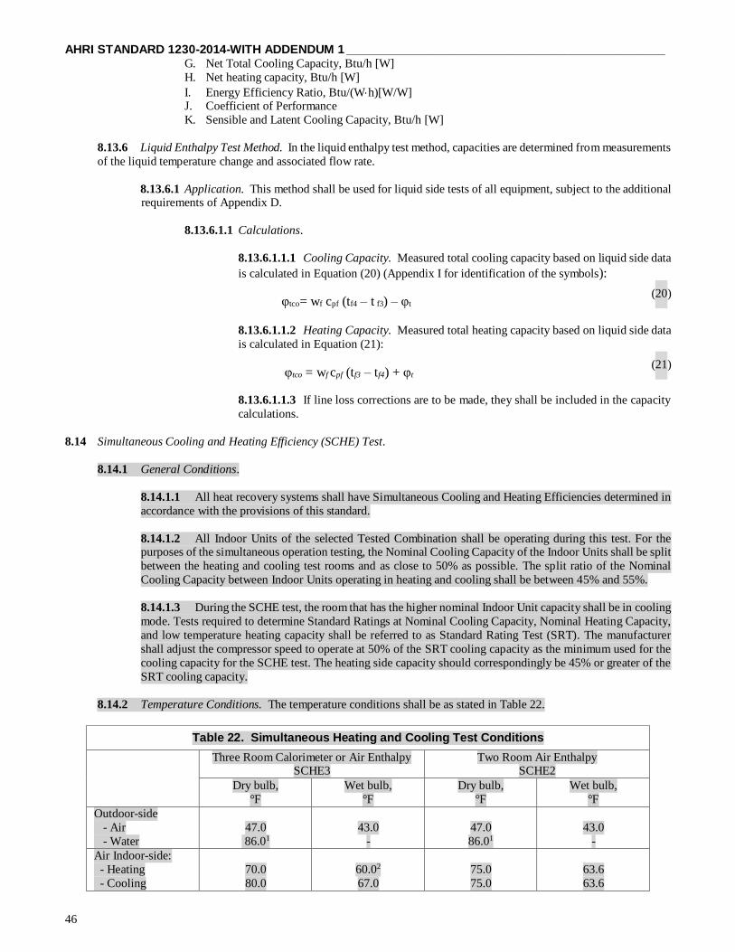
AHRI STANDARD 1230-2014-WITH ADDENDUM 1 ______________________________________________
46
G. Net Total Cooling Capacity, Btu/h [W]
H. Net heating capacity, Btu/h [W]
I. Energy Efficiency Ratio, Btu/(Wh)[W/W] J. Coefficient of Performance
K. Sensible and Latent Cooling Capacity, Btu/h [W]
8.13.6 Liquid Enthalpy Test Method. In the liquid enthalpy test method, capacities are determined from measurements
of the liquid temperature change and associated flow rate.
8.13.6.1 Application. This method shall be used for liquid side tests of all equipment, subject to the additional requirements of Appendix D.
8.13.6.1.1 Calculations.
8.13.6.1.1.1 Cooling Capacity. Measured total cooling capacity based on liquid side data
is calculated in Equation (20) (Appendix I for identification of the symbols):
φtco= wf cpf (tf4 – t f3) – φt (20)
8.13.6.1.1.2 Heating Capacity. Measured total heating capacity based on liquid side data
is calculated in Equation (21):
φtco = wf cpf (tf3 – tf4) + φt (21)
8.13.6.1.1.3 If line loss corrections are to be made, they shall be included in the capacity
calculations.
8.14 Simultaneous Cooling and Heating Efficiency (SCHE) Test.
8.14.1 General Conditions.
8.14.1.1 All heat recovery systems shall have Simultaneous Cooling and Heating Efficiencies determined in
accordance with the provisions of this standard.
8.14.1.2 All Indoor Units of the selected Tested Combination shall be operating during this test. For the purposes of the simultaneous operation testing, the Nominal Cooling Capacity of the Indoor Units shall be split
between the heating and cooling test rooms and as close to 50% as possible. The split ratio of the Nominal
Cooling Capacity between Indoor Units operating in heating and cooling shall be between 45% and 55%.
8.14.1.3 During the SCHE test, the room that has the higher nominal Indoor Unit capacity shall be in cooling
mode. Tests required to determine Standard Ratings at Nominal Cooling Capacity, Nominal Heating Capacity,
and low temperature heating capacity shall be referred to as Standard Rating Test (SRT). The manufacturer
shall adjust the compressor speed to operate at 50% of the SRT cooling capacity as the minimum used for the
cooling capacity for the SCHE test. The heating side capacity should correspondingly be 45% or greater of the
SRT cooling capacity.
8.14.2 Temperature Conditions. The temperature conditions shall be as stated in Table 22.
Table 22. Simultaneous Heating and Cooling Test Conditions
Three Room Calorimeter or Air Enthalpy SCHE3
Two Room Air Enthalpy SCHE2
Dry bulb,
°F
Wet bulb,
°F
Dry bulb,
°F
Wet bulb,
°F
Outdoor-side
- Air
- Water
47.0
86.01
43.0
-
47.0
86.01
43.0
-
Air Indoor-side:
- Heating
- Cooling
70.0
80.0
60.02
67.0
75.0
75.0
63.6
63.6

______________________________________________ AHRI STANDARD 1230-2014-WITH ADDENDUM 1
47
Table 22. Simultaneous Heating and Cooling Test Conditions (Continued)
Water Indoor-side:
- Heating - Cooling
68.0 80.6
59.02
66.2
74.3 74.3
62.7 62.7
Notes:
1. This value will change to 68.0 on January 1, 2019
2. This is the maximum temperature. Lesser temperatures are acceptable.
8.14.3 Air-flow Conditions. The test shall be conducted at the same indoor fan speed setting as for the other capacity
tests.
8.14.4 Test Conditions.
8.14.4.1 Preconditions. The test room reconditioning apparatus and the equipment under test shall be
operated until equilibrium conditions are attained, but for not less than one hour, before capacity data is
recorded.
8.14.4.2 Duration of Test. Data shall be recorded at least once every five minutes for at least seven
consecutive readings within the tolerance presented in ASHRAE Standard 37, Table 2A have been attained,
such that 30 minutes of Stable Conditions is achieved.
8.14.5 Three-room Air Enthalpy Method.
8.14.5.1 The Indoor Units in the cooling mode shall be assembled in one room and the Indoor Units in the
heating mode in another room. The Outdoor Unit shall be installed in the third room.
8.14.6 Two-room Air Enthalpy Method.
8.14.6.1 All Indoor Units, either operating in cooling or heating mode, are assembled in one indoor room.
The Outdoor Unit shall be installed in the other room.
8.14.6.2 All Indoor Units operating in the heating mode shall be connected to a common plenum, all Indoor
Units operating in the cooling mode shall be connected to another common plenum, both in accordance with
the requirements established in the Indoor air enthalpy test method described in ASHRAE 37.
8.14.1 Simultaneous Cooling and Heating Efficiency Capacity Ratings.
8.14.1.1 General Conditions.
8.14.1.1.1 All modular heat recovery systems shall have Simultaneous Cooling and Heating
Efficiencies determined in accordance with the provisions of this standard. All tests shall be carried
out in accordance with the requirements of Appendix E and ANSI/ASHRAE Standard 37.
8.14.1.1.2 All indoor units shall be functioning during this test. For the purposes of simultaneous
operation testing, one-half of indoor units shall operate in cooling and one-half of indoor units in
heating with a tolerance not to exceed a ratio of 45% to 55%, based upon the cooling capacity of the
indoor units.
8.14.1.1.3 The manufacturer shall state the inverter frequency of the compressor needed to operate
50% or more of the connected indoor units at their nominal heating capacity and the equipment shall
be maintained at that frequency.
8.14.1.2 Temperature Conditions. The temperature conditions shall be as stated in Table 22.
Table 22. Simultaneous Heating and Cooling Test Conditions
Three Room Calorimeter or Air Enthalpy
SCHE3
Two Room Air Enthalpy
SCHE2
Dry bulb
°F [°C]
Wet bulb
°F [°C]
Dry bulb
°F [°C]
Wet bulb
°F [°C]
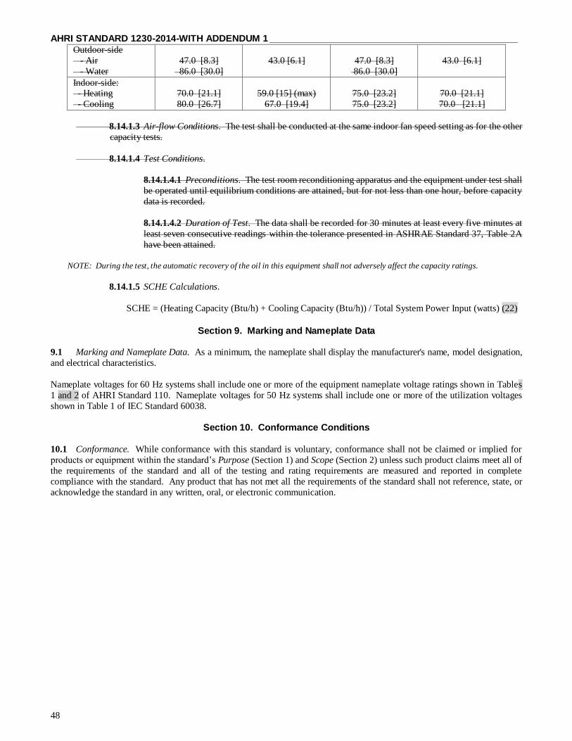
AHRI STANDARD 1230-2014-WITH ADDENDUM 1 ______________________________________________
48
Outdoor-side
- Air
- Water
47.0 [8.3]
86.0 [30.0]
43.0 [6.1]
47.0 [8.3]
86.0 [30.0]
43.0 [6.1]
Indoor-side: - Heating
- Cooling
70.0 [21.1]
80.0 [26.7]
59.0 [15] (max)
67.0 [19.4]
75.0 [23.2]
75.0 [23.2]
70.0 [21.1]
70.0 [21.1]
8.14.1.3 Air-flow Conditions. The test shall be conducted at the same indoor fan speed setting as for the other
capacity tests.
8.14.1.4 Test Conditions.
8.14.1.4.1 Preconditions. The test room reconditioning apparatus and the equipment under test shall
be operated until equilibrium conditions are attained, but for not less than one hour, before capacity
data is recorded.
8.14.1.4.2 Duration of Test. The data shall be recorded for 30 minutes at least every five minutes at
least seven consecutive readings within the tolerance presented in ASHRAE Standard 37, Table 2A
have been attained.
NOTE: During the test, the automatic recovery of the oil in this equipment shall not adversely affect the capacity ratings.
8.14.1.5 SCHE Calculations.
SCHE = (Heating Capacity (Btu/h) + Cooling Capacity (Btu/h)) / Total System Power Input (watts) (22)
Section 9. Marking and Nameplate Data
9.1 Marking and Nameplate Data. As a minimum, the nameplate shall display the manufacturer's name, model designation,
and electrical characteristics.
Nameplate voltages for 60 Hz systems shall include one or more of the equipment nameplate voltage ratings shown in Tables
1 and 2 of AHRI Standard 110. Nameplate voltages for 50 Hz systems shall include one or more of the utilization voltages
shown in Table 1 of IEC Standard 60038.
Section 10. Conformance Conditions
10.1 Conformance. While conformance with this standard is voluntary, conformance shall not be claimed or implied for
products or equipment within the standard’s Purpose (Section 1) and Scope (Section 2) unless such product claims meet all of
the requirements of the standard and all of the testing and rating requirements are measured and reported in complete
compliance with the standard. Any product that has not met all the requirements of the standard shall not reference, state, or
acknowledge the standard in any written, oral, or electronic communication.

______________________________________________ AHRI STANDARD 1230-2014-WITH ADDENDUM 1
49
APPENDIX A. REFERENCES – NORMATIVE
A1 Listed here are all standards, handbooks and other publications essential to the formation and implementation of the
standard. All references in this appendix are considered as part of this standard.
A1.1 AHRI Standard 110-2002 (formerly ARI Standard 110), Air-Conditioning and Refrigerating Equipment
Nameplate Voltages, Air-Conditioning Heating and Refrigeration Institute, 2002, 2111 Wilson Blvd., Suite 500,
Arlington, VA 22201, U.S.A.
A1.2 AHRI Standard 210/240-2008 (formerly ARI Standard 210/240), Unitary Air-Conditioning and Air-Source
Heat Pump Equipment, 2006, Air-Conditioning Heating and Refrigeration Institute, 2111 Wilson Blvd., Suite 500,
Arlington, VA 22201, U.S.A.
A1.3 AHRI Standard 340/360-2007 (formerly ARI Standard 340/360), Commercial and Industrial Unitary Air-
Conditioning and Heat Pump Equipment, 2004, Air-Conditioning Heating and Refrigeration Institute, 2111 Wilson
Blvd., Suite 500, Arlington, VA 22201, U.S.A.
A1.4 AHRI Standard 365 (I-P)-2009, Commerical and Industrial Unitary, Air Conditioning Condensing Units, 2002,
Air-Conditioning Heating and Refrigeration Institute, 2111 Wilson Blvd., Suite 500, Arlington, VA 22201, U.S.A.
A1.5 ANSI/ASHRAE Standard 37-2005, Methods of Testing for Rating Unitary Air-Conditioning and Heat Pump
Equipment, 2005, American Society of Heating, Refrigerating and Air-Conditioning Engineers, Inc., 1791 Tullie Circle
N.E., Atlanta, GA 30329, U.S.A.
A1.7 ASHRAE Terminology of Heating, Ventilation, Air-Conditioning and Refrigeration, Second Edition, 1991,
American Society of Heating, Refrigerating and Air-Conditioning Engineers, Inc., 1791 Tullie Circle, N.E., Atlanta, GA
30329, U.S.A.
A1.8 IEC Standard 60038, IEC Standard Voltages, 2002, International Electrotechnical Commission, 3, rue de
Varembe, P.O. Box 131, 1211 Geneva 20, Switzerland.
A1.9 ISO Standard 5151, Non-Ducted Air Conditioners And Heat Pumps — Testing And Rating For Performance
A1.10 ISO Standard 15042, 13256, 13253, Multiple Split-System Air-Conditioners And Air-To-Air Heat Pumps —
Testing And Rating For Performance
A1.11 ISO Standard 3966, Measurement of Fluid Flow In Closed Conduits — Velocity Area Method Using Pitot
Static Tubes,
A1.12 ISO Standard 5167, Air Distribution and Air Diffusion — Rules for Methods of Measuring Air Flow Rate In
an air handling duct
A1.13 ISO Standard 5221, Measurement Of Fluid Flow By Means Of Pressure Differential Devices — Part 1: Orifice
Plates, Nozzles And Venturi Tubes Inserted In Circular Cross-Section Conduits Running Full).
A1.14 Title 10, Code of Federal Regulations (CFR), Part 430, Subparts 430.2 and 430.32 (c), U.S. National Archives
and Records Administration, 8601 Adelphi Road, College Park, MD 20740-6001.
APPENDIX B. REFERENCES – INFORMATIVE
None.

AHRI STANDARD 1230-2014-WITH ADDENDUM 1 ______________________________________________
50
APPENDIX C. UNIFORM TEST METHOD FOR MEASURING THE ENERGY CONSUMPTION OF CENTRAL AIR
CONDITIONERS AND HEAT PUMPS – NORMATIVE
Foreword: This appendix to ARI Standard 1230-2008 is the “Uniform Test Method for Measuring the Energy
Consumption of Central Air Conditioners and Heat Pumps” Appendix M to Subpart B of Part 430, pages 59135 through
59180, Federal Register, Vol. 70, No. 195, Tuesday, October 11, 2005 as amended by the Federal Register, Vol. 72, No.
203, Monday, October 22, 2007 pages 59906 through 59934.
APPENDIX M to Subpart B of Part 430 – Uniform Test Method for Measuring the Energy Consumption of Central
Air Conditioners and Heat Pumps C1 U.S. Department of Energy (DOE) Appendix M to Subpart B of 10 CFR Part 430 - Uniform Test
Method for Measuring the Energy Consumption of Central Air Conditioners and Heat Pumps.
APPENDIX D. TEST REQUIREMENTS – NORMATIVE
D1 General Test Room Requirements.
D1.1 If an indoor condition test room is required, it shall be a room or space in which the desired test conditions can
be maintained within the prescribed tolerances. Air velocities in the vicinity of the equipment under test shall not exceed
8.2 ft/s [2.5 m/s].
D1.2 If an outdoor condition test room or space is required, it shall be of sufficient volume and shall circulate air in
a manner such that it does not change the normal air circulating pattern of the equipment under test. It shall be of such dimensions that the distance from any room surface to any equipment surface from which air is discharged is not less
than 71 inches (1.8 m) and the distance from any other room surface to any other equipment surface is not less than 39.4
inches (1.0 m), except for floor or wall relationships required for normal equipment installation. The room conditioning
apparatus should handle air at a rate not less than the outdoor airflow rate, and preferably should take this air from the
direction of the equipment air discharge and return it at the desired conditions uniformly and at low velocities.
D1.3 If the calorimeter room method is used with a facility having more than two rooms, then the additional rooms
shall also comply with the requirements of the calorimeter test method as described in D4. If the air enthalpy method is
used with a facility having more than two rooms, then the additional rooms shall also comply with the requirements of
the indoor air enthalpy test method as described in D5.
D2 Equipment Installation.
D2.1 The equipment to be tested shall be installed in accordance with the manufacturer’s installation instructions
using recommended installation procedures and accessories. If the equipment is capable of being installed in multiple
positions, all tests shall be conducted using the worst configuration. In all cases the manufacturer’s recommendations
with respect to distances from adjacent walls, amount of extensions through walls, etc., shall be followed.
D2.2 Ducted equipment rated at less than 8kW and intended to operate at external static pressures of less than 0.1
inches W.G. [25Pa] shall be tested at free delivery of air.
D2.3 No other alterations to the equipment shall be made except for the attachment of the required test apparatus and
instruments in the prescribed manner.
D2.4 If necessary, the equipment shall be evacuated and charged with the type and amount of refrigerant specified
in the manufacturer’s instructions.
D2.5 Refer to paragraph 6.1.7 to determine the minimum requirement for connecting refrigerant tubing.

______________________________________________ AHRI STANDARD 1230-2014-WITH ADDENDUM 1
51
D3 Static Pressure Measurements Across Indoor Coil.
D3.1 Equipment With A Fan And A Single Outlet.
D3.1.1 A short plenum shall be attached to the outlet of the equipment. This plenum shall have cross
sectional dimensions equal to the dimensions of the equipment outlets. A static pressure tap shall be added at
the center of each side of the discharge plenum, if rectangular, or at four evenly distributed locations along the circumference of an oval or round plenum. These four static pressure taps shall be manifolded together.
The minimum length of the discharge plenum and the location of the static pressure taps relative to the
equipment outlets shall be as shown in Figure D1, if testing a split-system, and as shown in Figure D2, if testing
a single-package unit.
Figure D1. External Static Pressure Measurement
D3.1.2 A short plenum should be attached to the inlet of the equipment. If used, the inlet plenum shall have
cross sectional dimensions of the equipment inlet. In addition, four static pressure taps shall be added and manifolded together. This plenum should otherwise be constructed as shown for the inlet plenum in Figure
D2, if testing a single-package unit, and as shown in Figure D3, if testing a split-system. (Note: Figure D3 is
referenced here for guidance even though it specifically applies to Ducted Systems tested without an indoor
fan.)

AHRI STANDARD 1230-2014-WITH ADDENDUM 1 ______________________________________________
52
Figure D2. External Static Pressure Measurements
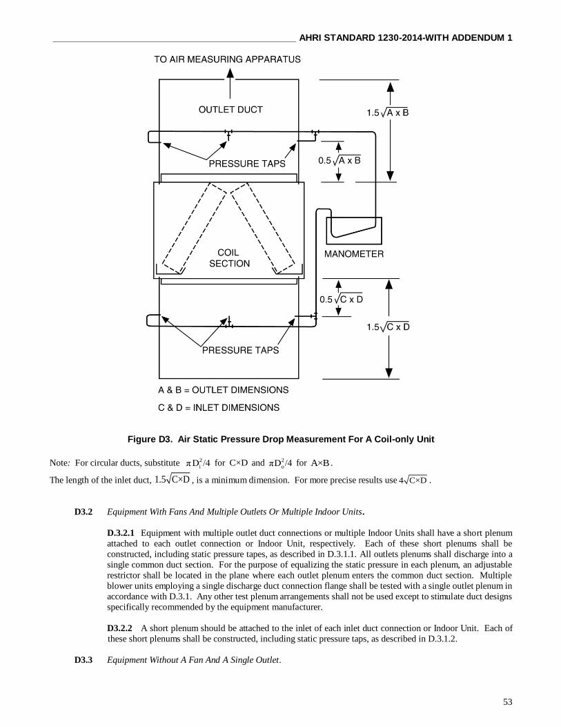
______________________________________________ AHRI STANDARD 1230-2014-WITH ADDENDUM 1
53
Figure D3. Air Static Pressure Drop Measurement For A Coil-only Unit
Note: For circular ducts, substitute 2
iπD /4 for C×D and 2
oπD /4 for A×B .
The length of the inlet duct, 1.5 C×D , is a minimum dimension. For more precise results use 4 C×D .
D3.2 Equipment With Fans And Multiple Outlets Or Multiple Indoor Units.
D.3.2.1 Equipment with multiple outlet duct connections or multiple Indoor Units shall have a short plenum
attached to each outlet connection or Indoor Unit, respectively. Each of these short plenums shall be
constructed, including static pressure tapes, as described in D.3.1.1. All outlets plenums shall discharge into a
single common duct section. For the purpose of equalizing the static pressure in each plenum, an adjustable
restrictor shall be located in the plane where each outlet plenum enters the common duct section. Multiple
blower units employing a single discharge duct connection flange shall be tested with a single outlet plenum in
accordance with D.3.1. Any other test plenum arrangements shall not be used except to stimulate duct designs
specifically recommended by the equipment manufacturer.
D3.2.2 A short plenum should be attached to the inlet of each inlet duct connection or Indoor Unit. Each of
these short plenums shall be constructed, including static pressure taps, as described in D.3.1.2.
D3.3 Equipment Without A Fan And A Single Outlet.
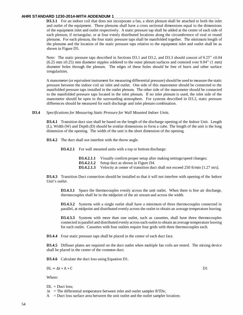
AHRI STANDARD 1230-2014-WITH ADDENDUM 1 ______________________________________________
54
D3.3.1 For an indoor coil that does not incorporate a fan, a short plenum shall be attached to both the inlet
and outlet of the equipment. These plenums shall have a cross sectional dimensions equal to the dimensions
of the equipment inlet and outlet respectively. A static pressure tap shall be added at the center of each side of
each plenum, if rectangular, or at four evenly distributed locations along the circumference of oval or round
plenums. For each plenum, the four static pressure taps shall be manifolded together. The minimum length of
the plenums and the location of the static pressure taps relative to the equipment inlet and outlet shall be as
shown in Figure D5.
Note: The static pressure taps described in Sections D3.1 and D3.2, and D3.3 should consist of 0.25” ±0.04
(6.25 mm ±0.25) mm diameter nipples soldered to the outer plenum surfaces and centered over 0.04” (1 mm)
diameter holes through the plenum. The edges of these holes should be free of burrs and other surface
irregularities.
A manometer (or equivalent instrument for measuring differential pressure) should be used to measure the static
pressure between the indoor coil air inlet and outlet. One side of this manometer should be connected to the
manifolded pressure taps installed in the outlet plenum. The other side of the manometer should be connected
to the manifolded pressure taps located in the inlet plenum. If no inlet plenum is used, the inlet side of the
manometer should be open to the surrounding atmosphere. For systems described in D3.2, static pressure
differences should be measured for each discharge and inlet plenum combination.
D3.4 Specifications for Measuring Static Pressure for Wall Mounted Indoor Units.
D3.4.1 Transition duct size shall be based on the length of the discharge opening of the Indoor Unit. Length
(L), Width (W) and Depth (D) should be similar dimensions to form a cube. The length of the unit is the long
dimension of the opening. The width of the unit is the short dimension of the opening.
D3.4.2 The duct shall not interfere with the throw angle.
D3.4.2.1 For wall mounted units with a top or bottom discharge:
D3.4.2.1.1 Visually confirm proper setup after making settings/speed changes;
D3.4.2.1.2 Setup duct as shown in Figure D4.
D3.4.2.1.3 Velocity at center of transition duct shall not exceed 250 ft/min [1.27 m/s].
D3.4.3 Transition Duct connection should be installed so that it will not interfere with opening of the Indoor
Unit’s outlet.
D3.4.3.1 Space the thermocouples evenly across the unit outlet. When there is free air discharge,
thermocouples shall be in the midpoint of the air stream and across the width.
D3.4.3.2 Systems with a single outlet shall have a minimum of three thermocouples connected in
parallel, at midpoint and distributed evenly across the outlet to obtain an average temperature leaving.
D3.4.3.3 Systems with more than one outlet, such as cassettes, shall have three thermocouples
connected in parallel and distributed evenly across each outlet to obtain an average temperature leaving
for each outlet. Cassettes with four outlets require four grids with three thermocouples each.
D3.4.4 Four static pressure taps shall be placed in the center of each duct face.
D3.4.5 Diffuser plates are required on the duct outlet when multiple fan coils are tested. The mixing device
shall be placed in the center of the common duct.
D3.4.6 Calculate the duct loss using Equation D1.
DL = ∆t ∗ A ∗ C D1
Where:
DL = Duct loss;
Δt = The differential temperature between inlet and outlet sampler RTDs;
A = Duct loss surface area between the unit outlet and the outlet sampler location;

______________________________________________ AHRI STANDARD 1230-2014-WITH ADDENDUM 1
55
C = Coefficient representing the insulation heat transfer value, calculated using Equation D2.
C = 1R⁄ D2
Where:
R = Insulation value (minimum shall be greater than or equal to R19).
D3.4.7 The total free air and closed duct balance check shall be verified by comparing total power, within a
tolerance of ± 2.0%.
Figure D4. Setup for Wall Mounted Indoor Units
1 – Indoor Unit, 2 – Duct Outlet, 3 – Transition Duct
D4 Calorimeter Test Method.
D4.1 General.
D4.1.1 The calorimeter provides a method for determining capacity simultaneously on both the indoor-side and the
outdoor-side. In the cooling mode, the indoor-side capacity determination should be made by balancing the cooling and
dehumidifying effects with measured heat and water inputs. The outdoor-side capacity provides a confirming test of the
cooling and dehumidifying effect by balancing the heat and water rejection on the condenser side with a measured
amount of cooling.
D4.1.2 The two calorimeter compartments, indoor side and outdoor side, are separated by an insulated partition having
an opening into which the non-ducted, single-packaged equipment is mounted. The equipment should be installed in a
manner similar to a normal installation. No effort should be made to seal the internal construction of the equipment to
prevent air leakage from the condenser side to the evaporator side or vice versa. No connections or alterations should
be made to the equipment which might in any way alter its normal operation.
D4.1.3 A pressure-equalizing device as illustrated in Figure D5 should be provided in the partition wall between the

AHRI STANDARD 1230-2014-WITH ADDENDUM 1 ______________________________________________
56
indoor-side and the outdoor-side compartments to maintain a balanced pressure between these compartments and also
to permit measurement of leakage, exhaust and ventilation air. This device consists of one or more nozzles of the type
shown in Figure D5, a discharge chamber equipped with an exhaust fan, and manometers for measuring compartment
and air-flow pressures.
Since the air flow from one compartment to the other may be in either direction, two such devices mounted in opposite
directions, or a reversible device, should be used. The manometer pressure pickup tubes should be so located as to be
unaffected by air discharged from the equipment or by the exhaust from the pressure-equalizing device. The fan or blower which exhausts air from the discharge chamber should permit variation of its air flow by any suitable means,
such as a variable speed drive, or a damper as shown in Figure D3. The exhaust from this fan or blower should be such
that it will not affect the inlet air to the equipment.
The pressure equalizing device should be adjusted during calorimeter tests or air-flow measurements so that the static
pressure difference between the indoor-side and outdoor-side compartments is not greater than .005’W.G. (1.25 Pa).
D4.1.4 The size of the calorimeter should be sufficient to avoid any restriction to the intake or discharge openings of
the equipment. Perforated plates or other suitable grilles should be provided at the discharge opening from the
reconditioning equipment to avoid face velocities exceeding 1.6 ft/s (0.5 m/s). Sufficient space should be allowed in
front of any inlet or discharge grilles of the equipment to avoid interference with the air-flow. Minimum distance from
the equipment to side walls or ceiling of the compartment(s) should be 39.4 inches (1 m), except for the back of console-
type equipment, which should be in normal relation to the wall. Ceiling-mounted equipment should be installed at a
minimum distance of 71 inches (1.8 m) from the floor. Table D1 gives the suggested dimensions for the calorimeter.
To accommodate peculiar sizes of equipment, it may be necessary to alter the suggested dimensions to comply with the
space requirements.
Table D1. Sizes of Calorimeter
Rated Cooling Capacity Of
Equipment1
Btu/h [W]
Suggested Minimum Inside Dimensions Of Each Room Of
Calorimeter
in [m]
Width Height Length
10,263 [3,000] 94.5 [2.40] 82.7 [2.1] 70.8 [1.8]
20,526 [6,000] 94.5 [2.40] 82.7 [2.1] 94.5 [2.4]
30,790 [9,000] 106.3 [2.70] 94.5 [2.4] 118.1 [3.0]
41,052 [12,000]2 118.1 [3.0] 94.5 [2.4] 145.7 [3.7]
Notes:
1) All figures are round numbers.
2) Larger capacity equipment will require larger calorimeters.
D4.1.5 Each compartment should be provided with reconditioning equipment to maintain specified airflow and
prescribed conditions. Reconditioning apparatus for the indoor-side compartment should consist of heaters to supply
sensible heat and a humidifier to supply moisture. Reconditioning apparatus for the outdoor-side compartment should
provide cooling, dehumidification, and humidification. The energy supply should be controlled and measured.
D4.1.6 When calorimeters are used for heat pumps, they should have heating, humidifying and cooling capabilities for
both rooms (see Figures D5 and D6) or other means, such as rotating the equipment, may be used as long as the rating
conditions are maintained.
D4.1.7 Reconditioning apparatus for both compartments should be provided with fans of sufficient capacity to ensure air-flows of not less than twice the quantity of air discharged by the equipment under test in the calorimeter. The
calorimeter should be equipped with means of measuring or determining specified wet-and dry-bulb temperatures in
both calorimeter compartments.
D4.1.8 It is recognized that in both the indoor-side and outdoor-side compartments, temperature gradients and air-flow
patterns result from the interaction of the reconditioning apparatus and test equipment. Therefore, the resultant conditions
are peculiar to and dependent upon a given combination of compartment size, arrangement and size of reconditioning
apparatus, and the air discharge characteristics of the equipment under test.

______________________________________________ AHRI STANDARD 1230-2014-WITH ADDENDUM 1
57
The point of measurement of specified test temperatures, both wet-bulb and dry-bulb, should be such that the following
conditions are fulfilled:
a) The measured temperatures should be representative of the temperature surrounding the equipment, and should
simulate the conditions encountered in an actual application for both indoor and outdoor sides, as indicated above.
b) At the point of measurement, the temperature of air should not be affected by air discharged from any piece of the equipment. This makes it mandatory that the temperatures are measured upstream of any re-circulation produced by the
equipment.
c) Air sampling tubes should be positioned on the intake side of the equipment under test.
D4.1.9 During a heating capacity test, it is necessary to monitor the temperature of the air leaving the indoor-side of
the heat pump to determine if its heating performance is being affected by a build-up of ice on the outdoor-side heat
exchanger. A single temperature measuring device, placed at the center the indoor air outlet, will be sufficient to indicate
any change in the indoor air discharge temperature caused by a build-up of ice on the outdoor-side heat exchanger.
D4.1.10 Interior surfaces of the calorimeter compartments should be of non-porous material with all joints sealed against
air and moisture leakage. The access door should be tightly sealed against air and moisture leakage by use of gaskets or
other suitable means.
Figure D5. Typical Calibrated Room-Type Calorimeter

AHRI STANDARD 1230-2014-WITH ADDENDUM 1 ______________________________________________
58
Figure D6. Typical Balanced Ambient Room-Type Calorimeter
D4.1.11 If defrost controls on the Heat Pump provide for stopping the indoor air-flow, provision shall be made to stop
the test apparatus air-flow to the equipment on both the indoor and outdoor-sides during a defrost period. If it is desirable
to maintain operation of the reconditioning apparatus during the defrost period, provision may be made to bypass the
conditioned air around the equipment as long as assurance is provided that the conditioned air does not aid in the
defrosting. A watt-hour meter shall be used for obtaining the integrated electrical input to the equipment under test.
D4.2 Calibrated Room-type Calorimeter.
D4.2.1 Heat leakage may be determined in either the indoor-side or outdoor-side compartment by the following
method: All openings shall be closed. Either compartment may be heated by electric heaters to a temperature of at least
19.8 ºF [11 ºC] above the surrounding ambient temperature. The ambient temperature should be maintained constant
within ±1.8 ºF [1 ºC] outside all six enveloping surfaces of the compartment, including the separating partition. If the construction of the partition is identical with that of the other walls, the heat leakage through the partition may be
determined on a proportional area basis.
D4.2.2 For calibrating the heat leakage through the separating partition alone, the following procedure may be used:
A test is carried out as described above. Then the temperature of the adjoining area on the other side of the separating
partition is raised to equal the temperature in the heated compartment, thus eliminating heat leakage through the partition,
while the 19.8ºF [11ºC] differential is maintained between the heated compartment and the ambient surrounding the other five enveloping surfaces.
The difference in heat input between the first test and second test will permit determination of the leakage through the
partition alone.
D4.2.3 For the outdoor-side compartment equipped with means for cooling, an alternative means of calibration may
be to cool the compartment to a temperature at least 19.8ºF [11ºC] below the ambient temperature (on six sides) and carry out a similar analysis.
D4.2.4 In addition to the two-room simultaneous method of determining capacities, the performance of the indoor
room-side compartment shall be verified at least every six months using an industry standard cooling capacity calibrating
device. A calibrating device may also be another piece of equipment whose performance has been measured by the
simultaneous indoor and outdoor measurement method at an accredited national test laboratory as part of an industry-
wide cooling capacity verification program.
D4.3 Balanced Ambient Room-type Calorimeter.
D4.3.1 The balanced ambient room-type calorimeter is shown in Figure D6 and is based on the principle of maintaining

______________________________________________ AHRI STANDARD 1230-2014-WITH ADDENDUM 1
59
the dry-bulb temperatures surrounding the particular compartment equal to the dry-bulb temperatures maintained within
that compartment. If the ambient wet-bulb temperature is also maintained equal to that within the compartment, the
vapor-proofing provisions of Section D4.1.10 are not required.
D4.3.2 The floor, ceiling, and walls of the calorimeter compartments shall be spaced a sufficient distance away from
the floor, ceiling, and walls of the controlled areas in which the compartments are located in order to provide a uniform
air temperature in the intervening space. It is recommended that this distance be at least 11.8 inches (0,3 m). Means shall be provided to circulate the air within the surrounding space to prevent stratification.
D4.3.3 Heat leakage through the separating partition shall be introduced into the heat balance calculation and may be
calibrated in accordance with Section D4.3.3, or may be calculated.
D4.3.4 It is recommended that the floor, ceiling, and walls of the calorimeter compartments be insulated so as to limit
heat leakage (including radiation) to no more than 10% of the test equipment's capacity, with an 19.8 ºF / 11 ºC temperature difference, or 1,026 Btu/h (300 W) for the same temperature difference, whichever is greater, as tested using
the procedure given in Section D4.3.2.
D4.4 Calculations Cooling Capacities.
D4.4.1 The energy flow quantities used to calculate the total cooling capacity based on indoor and outdoor-side
measurements are shown below in Figure D7.
Figure D7. Calorimeter Energy Flows During Cooling Capacity Tests
D4.4.2 The total cooling capacity on the indoor-side, as tested in either the calibrated or balanced ambient, room-type
calorimeter (see Figures D5 and D6), is calculated as follows:
φtci = Σ Pic + (hw1 – hw2) Wr + φlp + φ1r (D3)
Where:
φtci = Total Cooling Capacity on the indoor-side;
Σ Pic = Other power input to the indoor-side compartment, in Btu/h (watts);

AHRI STANDARD 1230-2014-WITH ADDENDUM 1 ______________________________________________
60
hw1 = Specific enthalpy of water or steam supplied to indoor-side compartment, in Btu/lb (J/kg);
hw2 = Specific enthalpy of condensed moisture leaving indoor-side compartment, in Btu/lb (J/kg);
Wr = Water vapor (rate) condensed by the equipment, in ft3/hr (g/s).
Note: If no water is introduced during the test, hw1 is taken at the temperature of the water in the humidifier tank of the
conditioning apparatus.
D4.4.3 When it is not practical to measure the temperature of the air leaving the indoor-side compartment to the
outdoor-side compartment, the temperature of the condensate may be assumed to be at the measured or estimated wet-
bulb temperature of the air leaving the test equipment.
D4.4.4 The water vapor (Wr) condensed by the equipment under test may be determined by the amount of water
evaporated into the indoor-side compartment by the reconditioning equipment to maintain the required humidity.
D4.4.5 Heat leakage φlp into the indoor-side compartment through the separating partition between the indoor-side and
outdoor-side compartments may be determined from the calibrating test or, in the case of the balanced-ambient room-
type compartment, may be based n calculations.
D4.4.6 The total cooling capacity on the outdoor-side, as tested in either the calibrated or balanced-ambient, room-
type calorimeter (see Figures D5 and D6) is calculated as follows:
φtco = φc - Σ Poc – Pt + (hw3 – hw2)Wr + φlp + φloo (D4)
Where:
φtco = Total Cooling Capacity on the outdoor-side;
Σ Poc = Sum of all total power input to the outdoor-side compartment, not including power to the equipment under
test, in Btu/h (watts);
Pt = Total power input to equipment, in Btu/h (watts);
hw3 = Specific enthalpy of condensate removed by air-treating coil in the outdoor-side compartment reconditioning
equipment, in Btu/lb (J/kg);
hw2 = Specific enthalpy of water supplied to the outdoor-side compartment, in Btu/lb (J/kg);
Wr = Water vapor (rate) condensed by the equipment, in ft3/hr (g/s).
D4.4.7 The heat leakage rate (φlp) into the indoor-side compartment through the separating partition between the
indoor-side and outdoor-side compartments may be determined from the calibrating test or, in the case of the balanced-
ambient room-type compartment, may be based on calculations.
Note: This quantity will be numerically equal to that used in equation D1 if, and only if, the area of the separating partition exposed to the outdoor-side is equal to the area exposed to the indoor-side compartment.
D4.4.8 The latent cooling capacity (room dehumidifying capacity) is calculated as follows:
φd = K1Wr (D5)
D4.4.9 The sensible cooling capacity is calculated as follows:
φsci = φtci -φd (D6)
D4.4.10 Sensible heat ratio is calculated as follows:
SHR = φsci / φtci (D7)
D4.5 Calculation Heating Capacities.
D4.5.1 The energy flow quantities used to calculate the total heating capacity based on indoor and outdoor-side measurements are shown below in Figure D8.

______________________________________________ AHRI STANDARD 1230-2014-WITH ADDENDUM 1
61
Figure D8. Calorimeter Energy Flows During Heating Capacity Tests
D4.5.2 Determination of the heating capacity by measurement in the indoor-side compartment of the calorimeter is
calculated as follows:
φhi = φlci + φt + φlr -ΣPic (D8)
Where:
ΣPic is the other power input to the indoor-side compartment (e.g. illumination, electrical and thermal power input
to the compensating device, heat balance of the humidification device), W.
D4.5.3 Determination of the heating capacity by measurement of the heat absorbing side is calculated for equipment
where the evaporator takes the heat from an air-flow as follows:
φho = ΣPoc + Pt + qwo (hw4 – hw5) + φt+ φ loo (D9)
Where:
ΣPoc = Total power input to the outdoor-side compartment with the exception of the power input to the equipment,
W; Pt = Total power input to equipment, in watts;
qwo = Water mass flow supplied to the outside compartment for maintaining the test conditions, kg/s;
hw4 = Specific enthalpy of the water supplied to the outdoor-side compartment, J/kg;
hw5 = Specific enthalpy of the condensed water (in the case of test condition, high) and frost, respectively (in the
case of test condition, H2 or H3) in the equipment, J/kg;
φloo = Heat flow through the remaining enveloping surfaces into the outdoor-side compartment, W.
D5 Indoor Air Enthalpy Test Method.
D5.1 General .
In the air-enthalpy method, capacities are determined from measurements of entering and leaving wet-and dry-bulb
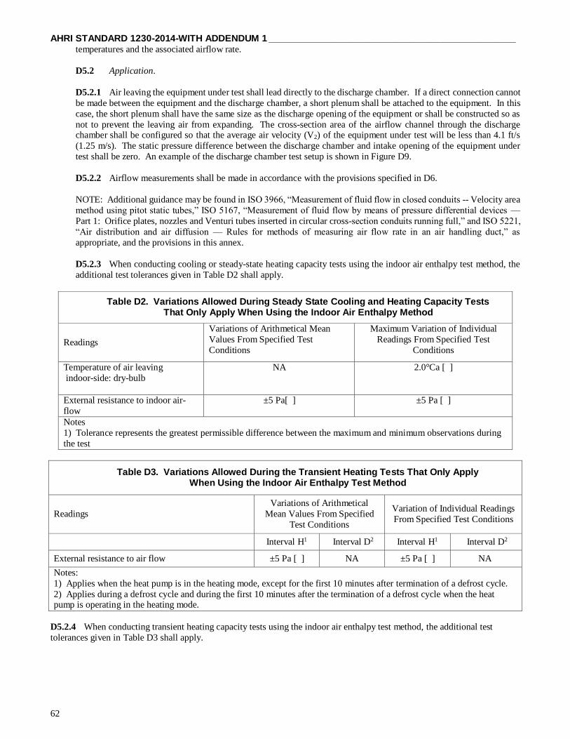
AHRI STANDARD 1230-2014-WITH ADDENDUM 1 ______________________________________________
62
temperatures and the associated airflow rate.
D5.2 Application.
D5.2.1 Air leaving the equipment under test shall lead directly to the discharge chamber. If a direct connection cannot
be made between the equipment and the discharge chamber, a short plenum shall be attached to the equipment. In this
case, the short plenum shall have the same size as the discharge opening of the equipment or shall be constructed so as
not to prevent the leaving air from expanding. The cross-section area of the airflow channel through the discharge chamber shall be configured so that the average air velocity (V2) of the equipment under test will be less than 4.1 ft/s
(1.25 m/s). The static pressure difference between the discharge chamber and intake opening of the equipment under
test shall be zero. An example of the discharge chamber test setup is shown in Figure D9.
D5.2.2 Airflow measurements shall be made in accordance with the provisions specified in D6.
NOTE: Additional guidance may be found in ISO 3966, “Measurement of fluid flow in closed conduits -- Velocity area
method using pitot static tubes,” ISO 5167, “Measurement of fluid flow by means of pressure differential devices —
Part 1: Orifice plates, nozzles and Venturi tubes inserted in circular cross-section conduits running full,” and ISO 5221,
“Air distribution and air diffusion — Rules for methods of measuring air flow rate in an air handling duct,” as
appropriate, and the provisions in this annex.
D5.2.3 When conducting cooling or steady-state heating capacity tests using the indoor air enthalpy test method, the
additional test tolerances given in Table D2 shall apply.
Table D2. Variations Allowed During Steady State Cooling and Heating Capacity Tests That Only Apply When Using the Indoor Air Enthalpy Method
Readings
Variations of Arithmetical Mean
Values From Specified Test
Conditions
Maximum Variation of Individual
Readings From Specified Test
Conditions
Temperature of air leaving
indoor-side: dry-bulb
NA 2.0°Ca [ ]
External resistance to indoor air-
flow
±5 Pa[ ] ±5 Pa [ ]
Notes
1) Tolerance represents the greatest permissible difference between the maximum and minimum observations during
the test
Table D3. Variations Allowed During the Transient Heating Tests That Only Apply When Using the Indoor Air Enthalpy Test Method
Readings
Variations of Arithmetical
Mean Values From Specified
Test Conditions
Variation of Individual Readings
From Specified Test Conditions
Interval H1 Interval D2 Interval H1 Interval D2
External resistance to air flow ±5 Pa [ ] NA ±5 Pa [ ] NA
Notes:
1) Applies when the heat pump is in the heating mode, except for the first 10 minutes after termination of a defrost cycle.
2) Applies during a defrost cycle and during the first 10 minutes after the termination of a defrost cycle when the heat pump is operating in the heating mode.
D5.2.4 When conducting transient heating capacity tests using the indoor air enthalpy test method, the additional test
tolerances given in Table D3 shall apply.

______________________________________________ AHRI STANDARD 1230-2014-WITH ADDENDUM 1
63
Figure D9. Discharge Chamber Requirements When Using the Indoor Air Enthalpy Test Method for Non-Ducted Unit
(D8) Where:
ha1 = Specific enthalpy of air entering indoor-side, J/kg of dry air;
ha2 = Specific enthalpy of air leaving indoor-side, J/kg of dry air;
v′n = Specific volume of air at nozzle, m3/kg of air-water vapor mixture;
Wn = Specific humidity at nozzle inlet, kg/kg of dry air.
(D10)
(D11)
(D12)
8
(D13)
8 D8
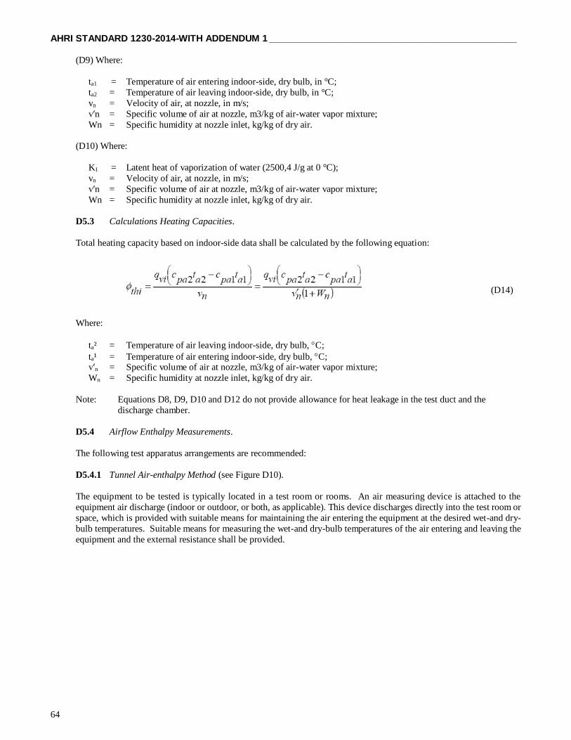
AHRI STANDARD 1230-2014-WITH ADDENDUM 1 ______________________________________________
64
(D9) Where:
ta1 = Temperature of air entering indoor-side, dry bulb, in °C;
ta2 = Temperature of air leaving indoor-side, dry bulb, in °C;
vn = Velocity of air, at nozzle, in m/s;
v′n = Specific volume of air at nozzle, m3/kg of air-water vapor mixture;
Wn = Specific humidity at nozzle inlet, kg/kg of dry air.
(D10) Where:
K1 = Latent heat of vaporization of water (2500,4 J/g at 0 °C);
vn = Velocity of air, at nozzle, in m/s;
v′n = Specific volume of air at nozzle, m3/kg of air-water vapor mixture;
Wn = Specific humidity at nozzle inlet, kg/kg of dry air.
D5.3 Calculations Heating Capacities.
Total heating capacity based on indoor-side data shall be calculated by the following equation:
Where:
ta² = Temperature of air leaving indoor-side, dry bulb, C;
ta¹ = Temperature of air entering indoor-side, dry bulb, C; v′n = Specific volume of air at nozzle, m3/kg of air-water vapor mixture;
Wn = Specific humidity at nozzle inlet, kg/kg of dry air.
Note: Equations D8, D9, D10 and D12 do not provide allowance for heat leakage in the test duct and the
discharge chamber.
D5.4 Airflow Enthalpy Measurements.
The following test apparatus arrangements are recommended:
D5.4.1 Tunnel Air-enthalpy Method (see Figure D10).
The equipment to be tested is typically located in a test room or rooms. An air measuring device is attached to the
equipment air discharge (indoor or outdoor, or both, as applicable). This device discharges directly into the test room or
space, which is provided with suitable means for maintaining the air entering the equipment at the desired wet-and dry-
bulb temperatures. Suitable means for measuring the wet-and dry-bulb temperatures of the air entering and leaving the
equipment and the external resistance shall be provided.
(D14)

______________________________________________ AHRI STANDARD 1230-2014-WITH ADDENDUM 1
65
Figure D10. Tunnel Air-Enthalpy Method
D5.4.2 Loop Air-enthalpy Method (see Figure D11).
This arrangement differs from the tunnel arrangement in that the air measuring device discharge is connected to suitable
reconditioning equipment which is, in turn, connected to the equipment inlet. The resulting test "loop" shall be sealed
so that air leakage at places that would influence capacity measurements does not exceed 1.0% of the test airflow rate.
The dry-bulb temperature of the air surrounding the equipment shall be maintained within ±5.4°F (±3.0°C) of the desired
test inlet dry-bulb temperature. Wet-bulb and dry-bulb temperatures and external resistance are to be measured by
suitable means.
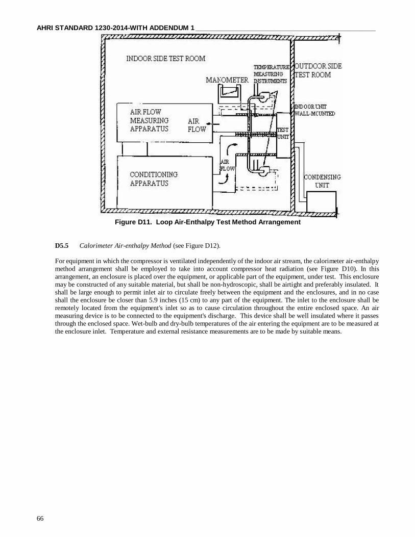
AHRI STANDARD 1230-2014-WITH ADDENDUM 1 ______________________________________________
66
Figure D11. Loop Air-Enthalpy Test Method Arrangement
D5.5 Calorimeter Air-enthalpy Method (see Figure D12).
For equipment in which the compressor is ventilated independently of the indoor air stream, the calorimeter air-enthalpy
method arrangement shall be employed to take into account compressor heat radiation (see Figure D10). In this
arrangement, an enclosure is placed over the equipment, or applicable part of the equipment, under test. This enclosure
may be constructed of any suitable material, but shall be non-hydroscopic, shall be airtight and preferably insulated. It
shall be large enough to permit inlet air to circulate freely between the equipment and the enclosures, and in no case
shall the enclosure be closer than 5.9 inches (15 cm) to any part of the equipment. The inlet to the enclosure shall be
remotely located from the equipment's inlet so as to cause circulation throughout the entire enclosed space. An air
measuring device is to be connected to the equipment's discharge. This device shall be well insulated where it passes
through the enclosed space. Wet-bulb and dry-bulb temperatures of the air entering the equipment are to be measured at
the enclosure inlet. Temperature and external resistance measurements are to be made by suitable means.

______________________________________________ AHRI STANDARD 1230-2014-WITH ADDENDUM 1
67
Figure D12. Calorimeter Air-Enthalpy Test Method Arrangement
D6 Airflow Measurement.
D6.1 Airflow Global Determination.
Air flow should be measured using the apparatus and testing procedures given in this annex. Airflow global quantities
are determined as mass flow rates. If air-flow quantities are to be expressed for rating purposes in volume flow rates,
such ratings shall state the conditions (pressure, temperature and humidity) at which the specific volume is determined.
D6.2 Airflow and Static Pressure.
Areas of nozzles should be determined by measuring their diameters to an accuracy of ± 0.2 percent in four locations
approximately 45 degrees apart around the nozzle in each of two places through the nozzle throat, one at the outlet and
the other in the straight section near the radius.
D6.3 Nozzle Apparatus.
D6.3.1 The nozzle apparatus consists of a receiving chamber and a discharge chamber separated by a partition in which
one or more nozzles are located (see Figure D12). Air from the equipment under test is conveyed via a duct to the
receiving chamber, passes through the nozzle or nozzles, and is then exhausted to the test room or channeled back to the
equipment's inlet.
D6.3.2 The nozzle apparatus and its connections to the equipment's inlet shall be sealed so that air leakage does not
exceed 1.0% of the airflow rate being measured.

AHRI STANDARD 1230-2014-WITH ADDENDUM 1 ______________________________________________
68
Figure D13. Airflow Measuring Apparatus
D6.3.3 The center-to-center distance between nozzles in use should be not less than 3 times the throat diameter of the
larger nozzle, and the distance from the center of any nozzle to the nearest discharge or receiving chamber side wall
should not be less than 1.5 times its throat diameter.
D6.3.4 Diffusers shall be installed in the receiving chamber (at a distance at least 1.5 times the largest nozzle throat diameter) upstream of the partition wall and in the discharge chamber (at a distance at least 2.5 times the largest nozzle
throat diameter) downstream of the exit plane of the largest nozzle.
D6.3.5 An exhaust fan, capable of providing the desired static pressure at the equipment's outlet, shall be installed in
one wall of the discharge chamber and means shall be provided to vary the capacity of this fan.
D6.3.6 The static pressure drop across the nozzle or nozzles shall be measured with a manometer or manometers. One
end of the manometer should be connected to a static pressure tap located flush with the inner wall of the receiving
chamber and the other end to a static pressure tap located flush with the inner wall of the discharge chamber, or
preferably, several taps in each chamber shall be connected to several manometers in parallel or manifolded to a single
manometer. Static pressure connections should be located so as not to be affected by air flow. Alternately, the velocity
head of the air stream leaving the nozzle or nozzles may be measured by a pitot tube as shown in Figure D12, but when
more than one nozzle is in use, the pitot tube reading should be determined for each nozzle.
D6.3.7 Means shall be provided to determine the air density at the nozzle throat.
D6.3.8 The throat velocity of any nozzle in use shall be not less than 49 ft/s (15 m/s), nor more than 115 ft/s (35 m/s).
D6.3.9 Nozzles shall be constructed in accordance with Figure D13, and applied in accordance with the provisions of
Sections D6.3.10 and D6.3.11
D6.3.10 Nozzle discharge coefficients for the construction shown in Figure D13, which have a throat length to throat
diameter ratio of 0.6, may be determined using,

______________________________________________ AHRI STANDARD 1230-2014-WITH ADDENDUM 1
69
for Reynolds numbers, Re, of 12,000 and above,
The definition of Reynolds number is
Where:
Vn = Air flow velocity at the throat of the nozzle;
Dn = Diameter of the throat of the nozzle;
ν = Kinematic viscosity of air.
D6.3.11 Nozzles may also be constructed in accordance with appropriate national standards, provided they can be used
in the apparatus described in Figure C.1 and result in equivalent accuracy.
D6.4 Static Pressure Measurements.
D6.4.1 The pressure taps shall consist of 0.25” ±0.04 (6.25 mm ±0.25 mm) diameter nipples soldered to the outer
plenum surfaces and centered over 1 mm diameter holes through the plenum. The edges of these holes should be free
of burrs and other surface irregularities.
D6.4.2 The plenum and duct section shall be sealed to prevent air leakage, particularly at the connections to the
equipment and the air measuring device, and shall be insulated to prevent heat leakage between the equipment outlet
and the temperature measuring instruments.
D6.5 Discharge Air-flow Measurements.
D6.5.1 The outlet or outlets of the equipment under test shall be connected to the receiving chamber by adapter ducting
of negligible air resistance, as shown in Figure D12.
D6.6 To measure the static pressure of the receiving chamber, a manometer shall have one side connected to one or more
static pressure connections located flush with the inner wall of the receiving chamber.
D6.7 Indoor-side Air-flow Measurements.
D6.7.1 The following readings should be taken:
a) barometric pressure;
b) nozzle dry-and wet-bulb temperatures or dew point temperatures;
c) static pressure difference at the nozzle(s) or optionally, nozzle velocity pressure;
(D15)
3
D13
(D16)
)3
D13
D13

AHRI STANDARD 1230-2014-WITH ADDENDUM 1 ______________________________________________
70
D6.7.2 Air mass flow rate through a single nozzle is determined as follows:
Where:
Cd = Coefficient of discharge, nozzle;
v′n = Specific volume of air at nozzle, m3/kg of air-water vapor mixture;
The expansion factor: Y is obtained from the next equation.
Y = 0.452 + 0.548α (C.4)
The pressure ratio: α is obtained from the next equation.
Air volume flow rate through a single nozzle is determined as follows:
Where:
Cd = Coefficient of discharge, nozzle;
v′n = Specific volume of air at nozzle, m3/kg of air-water vapor mixture;
vn = Velocity of air, at nozzle, m/s;
Wn = Specific humidity at nozzle inlet, kg/kg of dry air.
(D17)
3
D13
(D18)3
D13
(D19)
3
D13
(D20)
3
D13

______________________________________________ AHRI STANDARD 1230-2014-WITH ADDENDUM 1
71
Figure D14. Airflow Measuring Nozzle
D6.7.3 Air-flow through multiple nozzles shall be calculated in accordance with D6.6.2, except that the total flow rate
will be the sum of the q or q values for each nozzle used.
D6.8 Ventilation, Exhaust And Leakage Air-Flow Measurements - (Calorimeter Test Method).
D6.8.1 Ventilation, exhaust and leakage air-flows shall be measured using apparatus similar to that illustrated in Figure
D14 with the refrigeration system in operation and after condensate equilibrium has been obtained.
D6.8.2 With the equalizing device adjusted for a maximum static pressure differential between the indoor-side and
outdoor-side compartments of 0.004 inches W.G. (1 Pa), the following readings should be taken:
a) Barometric pressure;
b) Nozzle wet-and dry-bulb temperatures; c) Nozzle velocity pressure.
D.6.8.3 Air-flow values should be calculated in accordance with Section D6.7.2.
AXES OF
ELLIPSIS

AHRI STANDARD 1230-2014-WITH ADDENDUM 1 ______________________________________________
72
Figure D15. Pressure-Equalizing Device

______________________________________________ AHRI STANDARD 1230-2014-WITH ADDENDUM 1
73
APPENDIX E. HEAT RECOVERY TEST METHOD – NORMATIVE
E1 General.
The described methods in E3, E4 and E5 provide means to determine the total capacity of a heat recovery system.
E2 Heat Recovery Test.
E2.1 Heat Recovery Capacity Ratings.
E2.1.1 General Conditions.
E2.1.1.1 All modular heat recovery systems shall have heat recovery capacities and heat recovery efficiencies
(HRE) determined in accordance with the provisions of this appendix. All tests shall be carried out in
accordance with the requirements of Appendix D and the test methods described in E3, E4 and E5.
E2.1.1.2 All indoor units shall be functioning during this test (see E2.2), with the system operating at the
capacity ratio of 1, or as close as possible.
E2.1.1.3 The manufacturer shall state the inverter frequency of the compressor needed to give full-load
conditions and the equipment shall be maintained at that frequency.
Note 1: If the equipment cannot be maintained at steady state conditions by its normal controls, then the manufacturer shall
modify or over-ride such controls so that steady state conditions are achieved.
Note 2: To set up equipment for test which incorporates inverter-controlled compressors, skilled personnel with a knowledge
of the control software will be required. The manufacturer or his nominated agent should be in attendance when the equipment
is being installed and prepared for test.
E2.1.2 Temperature Conditions.
The temperature conditions shall be as stated in Table E1.
Table E1. Simultaneous Heating and Cooling Test Conditions
3 Room Calorimeter or Air enthalpy SCHE3
2 Room Air enthalpy SCHE2
Dry-bulb
Temperature
°F [°C]
Wet-bulb
Temperature
°F [°C]
Dry-bulb
Temperature
°F [°C]
Wet-bulb
Temperature
°F [°C]
Outdoor-side
- Air
- Water
47.0 [8.3]
86.0 [30.0]
43.0 [6.1]
47.0 [8.3]
86.0 [30.0]
43.0 [6.1]
Indoor-side:
- Heating
- Cooling
70.0 [21.1]
80.0 [26.7]
59.0 [15] (max)
67.0 [19.4]
75.0 [23.2]
75.0 [23.2]
70.0 [21.1]
70.0 [21.1]
E3 Three-Room Calorimeter Method.
E3.1 If measurements are made by the calorimeter method, then the testing of a heat recovery system shall need a
three-room calorimeter test facility. The Indoor Units in the cooling mode shall be assembled in one room and the
Indoor Units in the heating mode in the other. The outdoor unit shall be installed in the third room.

AHRI STANDARD 1230-2014-WITH ADDENDUM 1 ______________________________________________
74
E3.2 Each of the calorimeter rooms shall satisfy requirements described in Appendix D.
E3.3 For the results to be valid, the sum of the cooling capacity of the Indoor Units (see Section D4.4) and the power
input to the compressor and any fans shall differ by not more than 4% from the sum of the heating capacity of the Indoor
Units (see Section D4.5) and the heat from the outdoor unit. The heat from the outdoor unit may be negative if the unit
is absorbing heat (see Section D4.5.3) or positive if the unit is rejecting heat (see Section D4.4.6).
E4 Three-room Air Enthalpy Method.
E4.1 The indoor units in the cooling mode shall be assembled in one room and the Indoor Units in the heating mode
in another room. The outdoor unit shall be installed in the third room.
E4.2 The test facility shall satisfy the requirements of the Indoor air enthalpy test method described in E6.
E5 Two-room Air Enthalpy Method.
E5.1 All Indoor Units, either operating in cooling or heating mode, are assembled in one indoor room. The outdoor
unit shall be installed in the other room.
E5.2 All units operating in the heating mode shall be connected to a common plenum, all units operating in the
cooling mode shall be connected to another common plenum, both in accordance with the requirements established in
the Indoor air enthalpy test method described in Section E6.
E6 Indoor Air Enthalpy Test Method.
E6.1 General. In the air-enthalpy method, capacities are determined from measurements of entering and leaving wet-
bulb and dry-bulb temperatures and the associated airflow rate.
E6.2 Application.
E6.2.1 Air leaving the equipment under the test shall lead directly to the discharge chamber. If a direct
connection cannot be made between the equipment and the discharge chamber, a short plenum shall be attached
to the equipment. In this case, the short plenum shall have the same size as the discharge opening of the
equipment or shall be constructed so as not to prevent the leaving air from expanding. The cross-sectional area
of the airflow channel through the discharge chamber shall be such that the average air velocity will be less
than 1.25 m/s (ft/s) against the airflow rate of the equipment under test. The static pressure difference between
the discharge chamber and intake opening of the equipment under test shall be zero. An example of the
discharge chamber test setup is shown in Figure E1.
E6.2.2 Airflow measurements shall be made in accordance with the provisions specified in Appendix D.
Note: Additional guidance may be found in ISO 3966, “Measurement of fluid flow in closed conduits --
Velocity area method using pitot static tubes,” ISO 5167, “Measurement of fluid flow by means of pressure
differential devices — Part 1: Orifice plates, nozzles and Venturi tubes inserted in circular cross-section
conduits running full,” and ISO 5221, “Air distribution and air diffusion — Rules for methods of measuring air
flow rate in an air handling duct,” as appropriate, and the provisions in this annex.
E6.2.3 When conducting cooling or steady-state heating capacity tests using the indoor air enthalpy test method,
the additional test tolerances given in Table E2 shall apply

______________________________________________ AHRI STANDARD 1230-2014-WITH ADDENDUM 1
75
Table E2. Variations Allowed During Steady State Cooling and Heating Capacity Tests That Only Apply When Using the Indoor Air Enthalpy Method
Readings
Variations of Arithmetical Mean
Values From Specified Test
Conditions
Maximum Variation of Individual
Readings From Specified test
Conditions
Temperature of air leaving
indoor-side: dry-bulb NA 2.0°C1 [ ]
External resistance to indoor air-
flow ±5 Pa [ ] ±5 Pa [ ]
Note:
1) Tolerance represents the greatest permissible difference between the maximum and minimum observations during
the test
Table E3. Variations Allowed During the Transient Heating Tests That Only Apply When Using the Indoor Air Enthalpy Method
Readings Variations of Arithmetical
Mean Values From Specified
Test Conditions
Variation of Individual Readings From
Specified Test Conditions
Interval H1 Interval D2 Interval H1 Interval D2
External resistance to air flow ±5 Pa [ ] NA ±5 Pa [ ] NA
Notes:
1) Applies when the heat pump is in the heating mode, except for the first 10 minutes after termination of a defrost cycle.
2) Applies during a defrost cycle and during the first 10 minutes after the termination of a defrost cycle when the heat
pump is operating in the heating mode.
E2.4 When conducting transient heating capacity tests using the indoor air enthalpy test method, the additional test tolerances
given in Table E2 shall apply following equations:
Figure E1. Discharge Chamber Requirements When Using the Indoor Air Enthalpy Test Method for Non-Ducted Unit
De = √(4AB/π)

AHRI STANDARD 1230-2014-WITH ADDENDUM 1 ______________________________________________
76
(E1) Where:
ha1 = Specific enthalpy of air entering indoor-side, J/kg of dry air;
ha2 = Specific enthalpy of air leaving indoor-side, J/kg of dry air;
v′n = Specific volume of air at nozzle, m3/kg of air-water vapor mixture;
Wn = Specific humidity at nozzle inlet, kg/kg of dry air.
(E2) Where:
ta1 = Temperature of air entering indoor-side, dry bulb, in °C;
ta2 = Temperature of air leaving indoor-side, dry bulb, in °C;
vn = Velocity of air, at nozzle, in m/s;
v′n = Specific volume of air at nozzle, m3/kg of air-water vapor mixture;
Wn = Specific humidity at nozzle inlet, kg/kg of dry air.
(E3) Where:
K1 = Latent heat of vaporization of water (2500,4 J/g at 0 °C);
vn = Velocity of air, at nozzle, in m/s;
v′n = Specific volume of air at nozzle, m3/kg of air-water vapor mixture;
Wn = Specific humidity at nozzle inlet, kg/kg of dry air.
E6.3 Calculations Heating Capacities.
Total heating capacity based on indoor-side data shall be calculated by the following equation:
Where:
ta² = Temperature of air leaving indoor-side, dry bulb, C;
ta¹ = Temperature of air entering indoor-side, dry bulb, C; v′n = Specific volume of air at nozzle, m3/kg of air-water vapor mixture;
Wn = Specific humidity at nozzle inlet, kg/kg of dry air.
Note: Equations E1, E2, E3 and E5 do not provide allowance for heat leakage in the test duct and the
discharge chamber.
E6.4 Airflow Enthalpy Measurements.
The following test apparatus arrangements are recommended:
E6.4.1 Tunnel Air-Enthalpy Method (see Figure E2).
The equipment to be tested is typically located in a test room or rooms. An air measuring device is attached to the
equipment air discharge (indoor or outdoor, or both, as applicable). This device discharges directly into the test room or
space, which is provided with suitable means for maintaining the air entering the equipment at the desired wet-and dry-
bulb temperatures. Suitable means for measuring the wet-and dry-bulb temperatures of the air entering and leaving the
equipment and the external resistance shall be provided.
(E5)

______________________________________________ AHRI STANDARD 1230-2014-WITH ADDENDUM 1
77
E6.4.2 Loop Air-enthalpy Method (see Figure E3).
This arrangement differs from the tunnel arrangement in that the air measuring device discharge is connected to suitable
reconditioning equipment which is, in turn, connected to the equipment inlet. The resulting test "loop" shall be sealed
so that air leakage at places that would influence capacity measurements does not exceed 1.0% of the test airflow rate.
The dry-bulb temperature of the air surrounding the equipment shall be maintained within ±3.0°C of the desired test
inlet dry-bulb temperature. Wet- and dry-bulb temperatures and external resistance are to be measured by suitable means.
Figure E2. Tunnel Air Enthalpy Method

AHRI STANDARD 1230-2014-WITH ADDENDUM 1 ______________________________________________
78
Figure E3. Loop Air-Enthalpy Test Method Arrangement
E6.5 Calorimeter Air-enthalpy Method (see Figure E4).
For equipment in which the compressor is ventilated independently of the indoor air stream, the calorimeter air-enthalpy method
arrangement shall be employed to take into account compressor heat radiation (see Figure E.3). In this arrangement, an
enclosure is placed over the equipment, or applicable part of the equipment, under test. This enclosure may be constructed of
any suitable material, but shall be non hydroscopic, shall be airtight and preferably insulated. It shall be large enough to permit
inlet air to circulate freely between the equipment and the enclosures, and in no case shall the enclosure be closer than 15 cm
to any part of the equipment. The inlet to the enclosure shall be remotely located from the equipment's inlet so as to cause
circulation throughout the entire enclosed space. An air measuring device is to be connected to the equipment's discharge. This
device shall be well insulated where it passes through the enclosed space. Wet- and dry-bulb temperatures of the air entering
the equipment are to be measured at the enclosure inlet. Temperature and external resistance measurements are to be made by
suitable means.
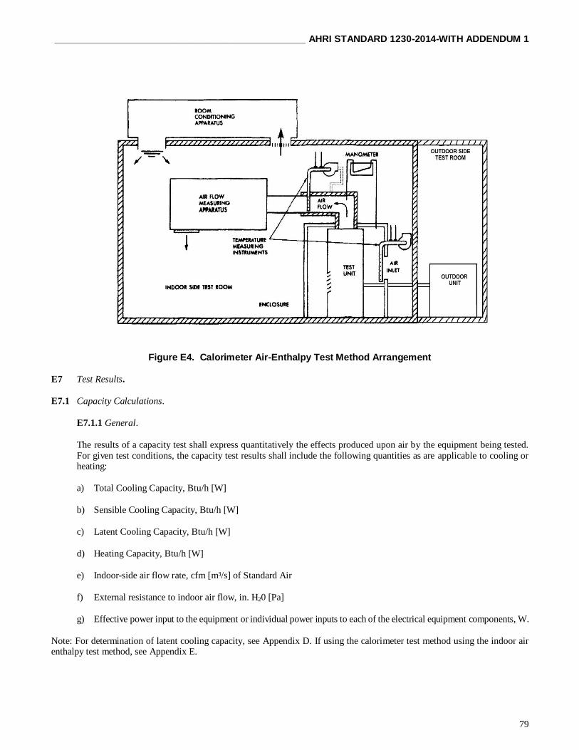
______________________________________________ AHRI STANDARD 1230-2014-WITH ADDENDUM 1
79
Figure E4. Calorimeter Air-Enthalpy Test Method Arrangement
E7 Test Results.
E7.1 Capacity Calculations.
E7.1.1 General.
The results of a capacity test shall express quantitatively the effects produced upon air by the equipment being tested.
For given test conditions, the capacity test results shall include the following quantities as are applicable to cooling or heating:
a) Total Cooling Capacity, Btu/h [W]
b) Sensible Cooling Capacity, Btu/h [W]
c) Latent Cooling Capacity, Btu/h [W]
d) Heating Capacity, Btu/h [W]
e) Indoor-side air flow rate, cfm [m³/s] of Standard Air
f) External resistance to indoor air flow, in. H20 [Pa]
g) Effective power input to the equipment or individual power inputs to each of the electrical equipment components, W.
Note: For determination of latent cooling capacity, see Appendix D. If using the calorimeter test method using the indoor air enthalpy test method, see Appendix E.

AHRI STANDARD 1230-2014-WITH ADDENDUM 1 ______________________________________________
80
E7.1.2 Adjustments.
Test results shall be used to determine capacities without adjustment for permissible variations in test conditions, except
that air enthalpies, specific volumes and isobaric specific heat capacities shall be corrected for deviations from saturation
temperature and standard barometric pressure.
E7.1.3 Cooling Capacity Calculations.
E7.1.3.1 An average cooling capacity shall be determined from the set of cooling capacities recorded over the data
collection period.
E7.1.3.2 An average electrical power input shall be determined from the set of electrical power inputs recorded over
the data collection period or from the integrated electrical power for the same interval for cases where an electrical
energy meter is used.
E7.1.3.3 Standard ratings of capacities shall include the effects of circulating-fan heat, but shall not include
supplementary heat. For units provided without a fan, the effect of the fan to be taken into account shall be calculated.
E7.1.4 Heating Capacity Calculations.
E7.1.4.1 Steady State Capacity Calculations.
E7.1.4.1.1 If the heating capacity test is conducted in accordance with the provisions of Section E7.1.4.1.2 or Section
E7.1.4.1.1.2, a heating capacity shall be calculated using data from each data sampling in accordance with Appendix D, if using the calorimeter test method, or if using the indoor air-enthalpy test method.
E7.1.4.1.2 Test Procedure: When a defrost cycle (whether automatically or manually-initiated) ends the preconditioning
period.
E7.1.4.1.2.1 If the quantity %ΔT exceeds 2.5 percent during the first 35 min of the data collection period, the heating
capacity test shall be designated a transient test. Likewise, if the heat pump initiates a defrost cycle during the
equilibrium period or during the first 35 min of the data collection period, the heating capacity test shall be designated
a transient test.
E7.1.4.1.2.2 If the conditions specified in 6.1.9.1 do not occur and the test tolerances are satisfied during both the
equilibrium period and the first 35 min of the data collection period, then the heat capacity test shall be designated a
Steady-State Test. Steady-State Tests shall be terminated after 35 min of data collection.
E7.1.4.1.3 Test Procedure: When a defrost cycle does not end the preconditioning period.
E7.1.4.1.3.1 If the heat pump initiates a defrost cycle during the equilibrium period or during the first 35 min of the data
collection period, the heating capacity test shall be restarted as specified in E7.1.4.1.3.3.
E7.1.4.1.3.2 If the quantity %T exceeds 2.5 percent any time during the first 35 min of the data collection period, the heating capacity test shall be restarted as specified in E7.1.4.1.3.3. Prior to the restart, a defrost cycle shall occur. This
defrost cycle may be manually initiated or delayed until the heat pump initiates an automatic defrost.
E7.1.4.1.3.3 If either E7.1.4.1.3.1 or E7.1.4.1.3.2 apply, then the restart shall begin 10 min after the defrost cycle
terminates with a new, hour-long equilibrium period. This second attempt shall follow the same requirements.
E7.1.4.1.3.4 If the conditions specified in either E7.1.4.1.3.1 or E7.1.4.1.3.2 do not occur and the test tolerances are
satisfied during both the equilibrium period and the first 35 min of the data collection period, then the heat capacity test
shall be designated a Steady-State Test. Steady-State Tests shall be terminated after 35 min of data collection.
E7.1.4.1.4 An average heating capacity shall be determined from the set of heating capacities recorded over the data
collection period.
E7.1.4.1.5 An average electrical power input shall be determined from the set of electrical power inputs recorded over
the data collection or from the integrated electrical power for the same data collection period.

______________________________________________ AHRI STANDARD 1230-2014-WITH ADDENDUM 1
81
E7.1.4.2 Transient Capacity Tests.
E7.1.4.2.1 If the heating capacity test is conducted in accordance with the provisions of transient testing, an average
heating capacity shall be determined. This average heating capacity shall be calculated as specified in Annex C if using
the calorimeter test method and as specified in Appendix D if using the indoor air-enthalpy test method.
E7.1.4.2.2 For equipment where one or more complete cycles occur during the data collection period, the following shall apply. The average heating capacity shall be determined using the integrated capacity and the elapsed time
corresponding to the total number of complete cycles that occurred over the data collection period. The average electrical
power input shall be determined using the integrated power input and the elapsed time corresponding to the total number
of complete cycles during the same data collection period as the one used for the heating capacity. [A complete cycle
consists of a heating period and a defrost period from defrost termination to defrost termination.]
E7.1.4.2.3 For equipment that does not conduct a complete cycle during the data collection period, the following shall
apply. The average heating capacity shall be determined using the integrated capacity and the elapsed time corresponding
to the total data collection period. (3 hours if using the indoor air-enthalpy test method; 6 hours if using the calorimeter
test method).The average electrical power input shall be determined using the integrated power input and the elapsed
time corresponding to the same data collection period as the one used for the heating capacity.
E7.1.4.2.4 For equipment in which a single defrost occurs during the test period, the following shall apply. The average
heating capacity shall be determined using the integrated capacity and the elapsed time corresponding to the total test
period (3 hours if using the indoor air-enthalpy test method; 6 hours if using the calorimeter test method). The average
electrical power input shall be determined using the integrated power input and the elapsed time corresponding to the
total test period.
E7.1.5 Power Input of Fans.
The fan power measured during the test shall be included in the declared power consumption and in the calculation of
efficiencies. Standard ratings of capacities shall include the effects of circulating-fan heat, but shall not include
supplementary heat. For units provided without a fan, the effect of the fan to be taken into account shall be calculated
according to Annex P.
E7.2 Data To Be Recorded.
The data to be recorded for the capacity tests are given in Table 15 for the indoor air enthalpy test method and Tables
16 and 17 for the room calorimeter test method. The tables identify the general information required but are not intended
to limit the data to be obtained. Electrical input values used for rating purposes shall be those measured during the
capacity tests.

AHRI STANDARD 1230-2014-WITH ADDENDUM 1 ______________________________________________
82
Table E4. Data To Be Recorded During The Indoor Air-Enthalpy Capacity Tests1,2
No. Data
1
2
3
4
5
6
7
8
9
10
11 12
13
14
15
16
17
18
19
Date
Observers
Barometric pressure, in. Hg (kPa)
Time of tests S
Power input to equipmenta, W
Energy input to equipmentb, Wh
Applied voltage(s), V
Current, A
Frequency, Hz
External resistance to air-flow for each indoor unit, Pa
Fan speed setting Setting of variable capacity compressor at full load.
Dry-bulb temperature of air entering equipment, ºF (ºC)
Wet-bulb temperature of air entering equipment, ºF (ºC)
Dry-bulb temperature of air leaving measuring device, ºF (ºC)
Wet-bulb temperature of air entering measuring device, ºF (ºC)
Outdoor dry-bulb and wet-bulb temperatures, ºF (ºC)
Volume flow rate of air and all relevant measurements for its calculation, cfm (m3/s)
Refrigerant charge added by the test house, lbs (kg)
Notes:
1) Total power input and, where required, input to equipment components
2) Energy input to equipment is required only during defrost operations
Table E5. Data To Be Recorded For Calorimeter Cooling Capacity Tests
No. Data
1
2
3
4 5
6
7
8
9
10
11
12
13
14
15
16
17
18
19 20
21
22
Date
Observers
Barometric pressure, , in. Hg (kPa)
Fan speed setting indoor and outdoor Applied voltage, V
Frequency, Hz
Total current input to equipment, amps
Total power input to equipmenta, W
Setting of variable capacity compressor at full load. Control dry-bulb and wet-bulb
temperature of air (indoor-side calorimeter compartment)b, ºC
Control dry-bulb and wet-bulb temperature of air (outdoor-side calorimeter compartment)b, ºC
Average air temperature outside the calorimeter if calibrated, (see Figure D7), ºC
Total power input to indoor-side and outdoor-side compartments, W
Quantity of water evaporated in humidifier, kg
Temperature of humidifier water entering indoor-side and outdoor-side (if used)
compartments or in humidifier tank, ºC
Cooling water flow rate through outdoor-side compartment heat-rejection coil, l3/s
Temperature of cooling water entering outdoor-side compartment, for heat-rejection coil, ºC
Temperature of cooling water leaving outdoor-side compartment, from heat-rejection coil, ºC
Temperature of condensed water leaving outdoor-side compartment, ºC
Mass of condensed water from equipment, lbs (kg) Volume of air-flow through measuring nozzle of the separating partition, m3/s
Air-static pressure difference across the separating partition of calorimeter compartments, Pa
Refrigerant charge added by the test house, lbs (kg)
Notes: 1) Total power input to the equipment, except if more than one external power connection is provided on the equipment;
record input to each connection separately
2) See E.1.3.2

______________________________________________ AHRI STANDARD 1230-2014-WITH ADDENDUM 1
83
Table E6. Data To Be Recorded For Calorimeter Heating Capacity Tests
No. Data
1
2
3
4
5
6
7
8
9
10
11 12
13
14
15
16
17
18
19
20
21
22
23
Date
Observers
Barometric pressure, kPa
Fan speed setting indoor and outdoor
Applied voltage, V
Frequency, Hz
Total current input to equipment, amps
Total power input to equipmenta, W
Setting of variable capacity compressor at full load.
Control dry-bulb and wet-bulb temperature of air (indoor-side calorimeter compartment)b, ºC
Control dry-bulb and wet-bulb temperature of air (outdoor-side calorimeter compartment)b, ºC Average air temperature outside the calorimeter if calibrated, (see Figure D8), ºC
Total power input to indoor-side and outdoor-side compartments, W
Quantity of water evaporated in humidifier, kg
Temperature of humidifier water entering indoor-side and outdoor-side (if used)
compartments or in humidifier tank, ºC
Cooling water flow rate through outdoor-side compartment heat-rejection coil, gL³/s or L/s, gpm
Temperature of cooling water entering outdoor-side compartment, for heat-rejection coil, ºC
Temperature of cooling water leaving outdoor-side compartment, from heat-rejection coil, ºC
Water condensed outdoor-side compartment, kg
Temperature of condensed water leaving outdoor-side compartment, ºC
Volume of air-flow through measuring nozzle of the separating partition, m3/s
Air-static pressure difference across the separating partition of calorimeter compartments, Pa
Refrigerant charge added by the test house, kg Notes:
1) Total power input to the equipment, except if more than one external power connection is provided on the equipment; record
input to each connection separately 2) See E.1.3.4
E7.3 Test Report.
E7.3.1 General Information.
As a minimum, the test report shall contain the following general information:
a) Date
b) Test Institute
c) Test l Location
d) Test Method(s) Used (calorimeter or air-enthalpy)
e) Test Supervisor
f) Test Object, Climate Type Designation (i.e., T1, T2, T3)
g) Reference To This AHRI Standard 1230
h) Description Of Test Set-up, Including Equipment Location
i) Nameplate Information (see 9.2)

AHRI STANDARD 1230-2014-WITH ADDENDUM 1 ______________________________________________
84
E7.3.2 Rating Test Results.
The values reported shall be the mean of the values taken over the test period.
E7.3.3 Performance Tests.
All relevant information regarding testing shall be reported.
E8 Published Ratings.
E8.1 Standard Ratings.
E8.1.1 Standard ratings shall be published for cooling capacities (sensible, latent and total), heating capacity, energy
efficiency ratio and coefficient of performance, as appropriate, for all systems produced in conformance to this standard.
These ratings shall be based on data obtained at the established rating conditions in accordance with the provisions of
this International Standard.
E8.1.2 The values of standard capacities shall be expressed in kilowatts, rounded to the three significant figures.
E8.1.3 The values of energy efficiency ratios and coefficients of performance shall be expressed in multiples rounded
to the three significant figures.
E8.1.4 Each capacity rating shall be followed by the corresponding test voltage see column 2 of Table E7 and
frequency rating.
Table E7. Cooling Capacity Test Conditions
T1 T2 T3
°F [°C] °F [°C] °F [°C]
Temperature of air entering indoor side1
— dry-bulb
— wet-bulb
80.6 [27.0]
66.2 [19.0]
69.8 [ 21.0]
59.0 [15.0]
84.2 [29.0]
66.2 [19.0]
Temperature of air surrounding unit — dry-bulb
— wet-bulb
95.0 [35.0]
75.2 [24.0]
80.6 [27.0]
66.2 [19.0]
114.8 [46.0]
75.2 [24.0]
Test Frequency2 Rated frequency
Test Voltage See Table F3
T1 - Standard cooling capacity rating conditions for moderate climates.
T2 - Standard cooling capacity rating conditions for cool climates.
T3 - Standard cooling capacity rating conditions for hot climates.
Notes:
1) The wet-bulb temperature condition is not required when testing air-cooled condensers which do not
evaporate the condensate. 2) Equipment with dual-rated frequencies shall be tested at each frequency.
E8.2 Other Ratings.
Additional ratings may be published based on conditions other than those specified as standard rating conditions, or based on
conditions specified in national regulations, or based on the testing of various combinations of operating evaporators and/or compressors if they are clearly specified and the data is determined by the methods specified in this Standard, or by analytical
methods which are verifiable by the test methods specified in this Standard.

______________________________________________ AHRI STANDARD 1230-2014-WITH ADDENDUM 1
85
APPENDIX F. INDIVIDUAL INDOOR UNIT CAPACITY TESTS – NORMATIVE
F1 General.
F1.1 The described methods provide a means to determine the capacity of an individual Indoor Unit, either operating on its
own with the other Indoor Units switched off, or with all indoor units operating.
All tests shall be made in accordance with the test requirements of Appendix D.
F2 The Calorimeter Method.
F2.1 If measurements are made by the calorimeter method, then the testing of an individual unit, with all others operating,
will need at least a three-room calorimeter test facility. If only one unit is operating, a two-room calorimeter will suffice. Each
calorimeter shall satisfy the calorimeter test method requirements described in Appendix D.
F3 The Air-Enthalpy Method.
F3.1 If measurements are made by the air-enthalpy method, then the testing shall be done with one or more indoor rooms and
one or more air measuring devices connected to the Indoor Units. The outdoor unit shall be situated at least in an environmental
test room.
F3.2 The test facility shall satisfy the indoor air enthalpy test method requirements described in Appendix E, except that the
individual Indoor Unit to be tested shall have its own plenum and air flow measuring device.
F4 Temperature Conditions.
F4.1 The temperature conditions stated in Table F2, Columns T1, T2 and T3, shall be considered standard rating conditions
for the determination of cooling capacity.
F4.2 Equipment manufactured for use in a moderate climate similar to that specified in Table F2, Column T1 only, shall have
a rating determined by tests conducted at these specified Table 1 conditions and shall be designated type T1 equipment.
F4.3 Equipment manufactured for use in a cool climate similar to that specified in Table F2, Column T2 only, shall have a
rating determined by tests conducted at these specified Table 1 conditions and shall be designated type T2 equipment.
F4.4 Equipment manufactured for use in a hot climate similar to that specified in Table F2, Column T3 only, shall have a
rating determined by tests conducted at these specified Table 1 conditions and shall be designated type T3 equipment.
F4.5 Equipment manufactured for use in more than one of the types of climate defined in Table F2, Columns T1, T2 and T3,
shall have the rating determined by test for each of the specified Table 1 conditions for which they have been designated and
tested.

AHRI STANDARD 1230-2014-WITH ADDENDUM 1 ______________________________________________
86
Table F1. Pressure Requirement for Comfort Air Conditioners
Standard Capacity
Ratings kW
Minimum External Static
Pressure1 Pa
Minimum External Static
Pressure1 in H20
0 < Q < 8 25 0.10
8 ≤ Q < 12 37 0.15
12 ≤ Q < 20 50 0.20
20 ≤ Q < 30 62 0.25
30 ≤ Q < 45 75 0.30
45 ≤ Q < 82 100 0.40
82 ≤ Q < 117 125 0.50
117 ≤ Q < 147 150 0.60
Q > 147 175 0.70
Note:
1) For equipment tested without an air filter installed, the minimum external static pressure shall be
increased by 0.040” WC / 10 Pa.
Table F2. Cooling Capacity Test Conditions
T1 T2 T3
°F [°C] °F [°C] °F [°C]
Temperature of air entering indoor side1
— dry-bulb
— wet-bulb
80.6 [27.0]
66.2 [19.0]
69.8 [21.0]
59.0 [15.0]
84.2 [ 29.0]
66.2 [19.0]
Temperature of air surrounding unit — dry-bulb
— wet-bulb
95.0 [35.0]
75.2 [24.0]
80.6 [27.0]
66.2 [19.0]
114.8 [46.0]
75.2 [24.0]
Test Frequency2 Rated frequency
Test Voltage See Table F3
T1 - Standard Cooling Capacity rating conditions for moderate climates.
T2 - Standard Cooling Capacity rating conditions for cool climates.
T3 - Standard Cooling Capacity rating conditions for hot climates.
Notes:
1) The wet-bulb temperature condition is not required when testing air-cooled condensers which do not
evaporate the condensate. 2) Equipment with dual-rated frequencies shall be tested at each frequency.
Table F3. Voltages for Capacity and Performance Tests (Except the maximum cooling and the maximum heating tests)
Rated (nameplate) Voltages1 Test Voltage
90 to 109
110 to 127
180 to 207
208 to 253
254 to 341
342 to 420
421 to 506
507 to 633
100
115
200
230
265
400
460
575
Note:
1) For equipment with dual-rated voltages such as 115/230 and 220/440, the test voltages would
be 115 and 230 volts in the first example, and 230 and 460 volts in the second example. For
equipment with an extended voltage range, such as 110-120 volts or 220-240 volts, the test voltage would be 115 volts or 230 volts, respectively. Where the extended voltage range spans two or
more of the rated voltage ranges, the mean of the rated voltages shall be used to determine the test
voltage from the table. (EXAMPLE: For equipment with an extended voltage range of 200-220
volts, the test voltage would be 230 volts, based on the mean voltage of 210 volts)

______________________________________________ AHRI STANDARD 1230-2014-WITH ADDENDUM 1
87
F5 Airflow Conditions.
F5.1 General.
This section covers air flow settings for ducted, non-ducted and units supplied without a fan.
Ducted Indoor Units rated at less than 8kW and intended to operate at an external static pressure of less than 25 Pa shall be tested as Non-ducted Indoor Units
F5.2 Air Flow Setting for Non-ducted Indoor Units Measured by Air Enthalpy Method.
F5.2.1 Tests shall be conducted with 0 Pa static pressure maintained at the air discharge of the equipment. All air
quantities shall be expressed as m³/s of Standard Air as defined in Appendix E.
F5.2.2 Air flow measurements shall be made in accordance with the provisions specified in this Appendix and in
ASHRAE Standard 37.
F5.3 Air Flow Setting for Ducted Indoor Units.
The air flow rate shall be specified by the manufacturer. This flow rate shall be for full load cooling and be expressed in terms
of standard air conditions and correspond to a compressor not operating.
F5.3.1 Air Flow Setting Procedure for Ducted Indoor Units.
The airflow rate setting shall be made when the fan only is operating, at an ambient temperature between 20.0°C to
30.0°C and relative humidity between 30% and 70%. The Airflow Settings of the units shall be in accordance with
Appendices D and F.
The rated airflow rate given by the manufacturer shall be set and the resulting external static pressure (ESP) measured.
The measured ESP shall be larger than the ESP for rating, defined in Table 1,. If the unit has an adjustable speed, it shall
be adjusted to the lowest speed that provides the ESP for rating or greater.
F5.3.2 ESP for Rating.
1) If the rated ESP stated by the manufacturer is greater than or equal to the minimum value given in table
1, the stated rated ESP is used as the ESP for rating.
2) If the rated ESP stated by the manufacturer is smaller than the minimum value given in table 1, and
larger than or equal to the 80% of the maximum ESP, the stated rated ESP is used as the ESP for rating.
The maximum ESP may either be specified by the manufacturer or be picked up from fan curves provided
by the manufacturer.
3) If the rated ESP specified by the manufacturer is smaller than the minimum value given in table 1, and
smaller than the 80% of the maximum ESP, the value of Table E1 or 80% of the maximum ESP, whichever
the smaller is used as the ESP for rating.
4) If the rated ESP is not specified by the manufacturer, the value of table 1 or 80% of the maximum ESP,
whichever the smaller is used as the ESP for rating.
The flowchart of selecting the ESP for rating is shown in Figure 1.
When the determined ESP for rating is smaller than 0.10” WC / 25Pa, the unit can be considered as a non-ducted Indoor
Unit.

AHRI STANDARD 1230-2014-WITH ADDENDUM 1 ______________________________________________
88
Figure F1. Flowchart Of Selecting ESP For Rating Ducted Indoor Units
F5.4 Outdoor Airflow.
F5.4.1 General.
If the outdoor airflow is adjustable, all tests shall be conducted at the outdoor-side air quantity or fan control setting that
is specified by the manufacturer. Where the fan is non-adjustable, all tests shall be conducted at the outdoor-side air
volume flow rate inherent in the equipment when operated with the following in place: all of the resistance elements
associated with inlets, louvers, and any ductwork and attachments considered by the manufacturer as normal installation
practice. Once established, the outdoor-side air circuit of the equipment shall remain unchanged throughout all tests
prescribed herein, except to adjust for any change caused by the attachment of the air-flow measuring device when using
the outdoor air-enthalpy test method (see Appendix D).
F5.4.2 Test Method.
The air flow settings of the units shall be in accordance with Appendix D.

______________________________________________ AHRI STANDARD 1230-2014-WITH ADDENDUM 1
89
F5.4.3 Unit Supplied Without Indoor Fan.
If no fan is supplied with the unit i.e. coil only units, the requirements in Appendix D.
F5.5 Test Conditions.
F5.5.1 Preconditions.
The test room reconditioning apparatus and the equipment under test shall be operated until equilibrium conditions are
attained. Equilibrium conditions as required by 8.3 shall be maintained for not less than one hour, before capacity test
data are recorded.
F5.5.1.1 Testing Requirements.
The test capacity shall include the determination of the sensible, latent and total cooling capacity as
determined on the indoor-side.
F5.5.1.2 Duration of Test.
The data shall be recorded at equal intervals that span one minute or less. The recording of the data shall
continue for at least a 30 minute period during which the tolerances specified in 8.3 shall be met.
F5.6 Defrost Operations.
F5.6.1 Overriding of automatic defrost controls shall be prohibited. The controls may only be overridden when
manually initiating a defrost cycle during preconditioning.
F5.6.2 Any defrost cycle, whether automatically or manually initiated, that occurs while preparing for or conducting
a heating capacity test shall always be automatically terminated by the action of the heat pump’s defrost controls.
F5.6.3 If the heat pump turns the indoor fan off during the defrost cycle, airflow through the indoor coil shall cease.
F5.7 Test Procedure – General Description.
F5.7.1 The test procedure consists of three periods: a preconditioning period, a equilibrium period, and a data
collection period. The duration of the data collection period differs depending upon whether the heat pump’s operation
is steady-state or transient. In the case of transient operation, in addition, the data collection period specified when
using the indoor air enthalpy method is different than the data collection period required if using the calorimeter
method.
F5.8 Preconditioning Period.
F5.8.1 The test room reconditioning apparatus and the heat pump under test shall be operated until the test tolerances
specified in Section 8.3 are attained for at least 10 minutes.
F5.8.2 A defrost cycle may end a preconditioning period. If a defrost cycle does end a preconditioning period, the
heat pump shall operate in the heating mode for at least 10 minutes after defrost termination prior to beginning the
equilibrium period.
F5.8.3 It is recommended that the preconditioning period end with an automatic or manually induced defrost cycle
when testing at the H2 and H3 temperature conditions.

AHRI STANDARD 1230-2014-WITH ADDENDUM 1 ______________________________________________
90
F5.9 Equilibrium Period.
F5.9.1 The equilibrium period immediately follows the preconditioning period.
F5.9.2 A complete equilibrium period is one hour in duration.
F5.9.3 Except as specified in Section F5.1.11.3, the heat pump shall operate while meeting the 8.3 test tolerances.
F5.10 Data Collection Period.
F5.10.1 The data collection period immediately follows the equilibrium period.
F5.10.2 Data shall be collected as specified for the chosen 8.1 test method(s). If using the calorimeter method, heating
capacity shall be calculated as specified in Appendix D. If using the indoor air enthalpy method, heating capacity shall
be calculated as specified in Appendix E. For cases where one of the confirming test methods from Section 8.1.3.1 is
used, heating capacity shall be calculated as specified in the appropriate appendix.
F5.10.3 An integrating electrical power (watt-hour) meter or measuring system shall be used for measuring the
electrical energy supplied to the equipment. During defrost cycles and for the first 10 minutes following a defrost
termination, the meter or measuring system shall have a sampling rate of at least every 10 seconds.
F5.10.4 Except as specified in Sections F5.10.3 and F5.10.5, data shall be sampled at equal intervals that span every
30 seconds or less.
F5.10.5 During defrost cycles, plus the first 10 minutes following defrost termination, certain data used in evaluating
the integrated heating capacity of the heat pump shall be sampled at equal intervals that span every 10 seconds or less.
When using the indoor air enthalpy method, these more-frequently sampled data include the change in indoor-side dry
bulb temperature. When using the calorimeter method, these more frequently sampled data include all measurements
required to determine the indoor-side capacity.
F5.10.6 For heat pumps that automatically cycle off the indoor fan during a defrost, the contribution of the net heating
delivered and/or the change in indoor-side dry bulb temperature shall be assigned the value of zero when the indoor
fan is off, if using the indoor air enthalpy method. If using the calorimeter test method, the integration of capacity
shall continue while the indoor fan is off.
F5.10.7 For both the indoor air-enthalpy and the calorimeter test methods, the difference between the dry bulb
temperature of the air leaving and entering the indoor coil shall be measured. For each 5-minute interval during the
data collection period, an average temperature difference shall be calculated, ∆T i(τ). The average temperature
difference for the first 5 minutes of the data collection period, , ∆T i(τ = 0), shall be saved for the purpose of calculating
the following percent change
F5.11 Test Procedure. When a defrost cycle (whether automatically or manually-initiated) ends the preconditioning period
F5.11.1 If the quantity %∆T exceeds 2.5 percent during the first 35 minutes of the data collection period, the heating
capacity test shall be designated a transient test. Likewise, if the heat pump initiates a defrost cycle during the
equilibrium period or during the first 35 minutes of the data collection period, the heating capacity test shall be
designated a transient test.
F5.11.2 If the conditions specified in 6.1.9.1 do not occur and the 8.3 test tolerances are satisfied during both the
equilibrium period and the first 35-minutes of the data collection period, then the heat capacity test shall be designated
a Steady-State Test. Steady-State Tests shall be terminated after 35 minutes of data collection.

______________________________________________ AHRI STANDARD 1230-2014-WITH ADDENDUM 1
91
F5.12 Test Procedure. When a defrost cycle does not end the 5.8 preconditioning period.
F5.12.1 If the heat pump initiates a defrost cycle during the equilibrium period or during the first 35 minutes of the
data collection period, the heating capacity test shall be restarted as specified in Section 5F.1.10.3.
F5.12.2 If the quantity %∆T exceeds 2.5 percent any time during the first 35 minutes of the data collection period,
the heating capacity test shall be restarted as specified in Section F5.12.3. Prior to the restart, a defrost cycle shall occur. This defrost cycle may be manually initiated or delayed until the heat pump initiates an automatic defrost.
F5.12.3 If either Section F5.12.1 or F5.12.2 apply, then the restart shall begin 10 minutes after the defrost cycle
terminates with a new, hour-long equilibrium period. This second attempt shall follow the requirements of Sections
F5.1.7 and F5.10, and the test procedure of Section F5.21
F5.12.4 If the conditions specified in Section F5.12.1 or F5.12.2 do not occur and the test tolerances are satisfied
during both the equilibrium period and the first 35 minutes of the data collection period, then the heat capacity test
shall be designated a Steady-State Test. Steady-State Tests shall be terminated after 35 minutes of data collection.
F5.13 Test Procedure for Transient Tests.
F5.131 When, in accordance with Section F5.11.1, a heating capacity test is designated a transient test, the adjustments
specified in Sections F5.13.2 to F5.13.5 shall apply.
F5.13.2 The outdoor air-enthalpy test method shall not be used and its associated outdoor-side measurement apparatus
shall be disconnected from the heat pump. In all cases, the normal outdoor-side airflow of the heat pump shall not be disturbed. Use of other confirming test methods is not required.
F5.13.3 To constitute a valid transient heating capacity tests, the test tolerances specified in Table 4 shall be achieved
during both the equilibrium period and the data collection period. As noted in Table 4, the test tolerances are specified
for two sub-intervals. Interval H consists of data collected during each heating interval, with the exception of the first
10 minutes after defrost termination. Interval D consists of data collected during each defrost cycle plus the first 10
minutes of the subsequent heating interval.
F5.13.4 The test tolerance parameters in Table F4 shall be sampled throughout the equilibrium and data collection
periods. All data collected during each interval, H or D, shall be used to evaluate compliance with the Table 4 test
tolerances. Data from two or more H intervals or two or more D intervals shall not be combined and then used in
evaluating Table F4 compliance. Compliance is based on evaluating data from each interval separately.
F5.13.5 If using the indoor air enthalpy method, the data collection period shall be extended until 3 hours have elapsed
or until the heat pump completes three complete cycles during the period, whichever occurs first. If at an elapsed time
of 3 hours, the heat pump is conducting a defrost cycle, the cycle shall be completed before terminating the collection
of data. A complete cycle consists of a heating period and a defrost period, from defrost termination to defrost termination
F5.13.6 If using the calorimeter method, the data collection period shall be extended until 6 hours have elapsed or
until the heat pump completes six complete cycles during the period, whichever occurs first. If at an elapsed time of
6 hours, the heat pump is conducting a defrost cycle, the cycle shall be completed before terminating the collection of
data. A complete cycle consists of a heating period and a defrost period, from defrost termination to defrost termination.
Note: Consecutive cycles should be repetitive with similar frost and defrost intervals before selecting data used for
calculating the integrated capacity and power.
F5.13.7 Because of the confirming test method requirement of Section 8.1.3.1, the outdoor air enthalpy test apparatus
may have to be disconnected from the heat pump, as specified in Section F5.13.2, during a heating capacity test. If
removal during a test is required, the changeover interval shall not be counted as part of the elapsed time of the
equilibrium or data collection periods. The changeover interval shall be defined as starting with the instant the heating
capacity test is designated a transient test and ending when the Table 4 test tolerances are first re-established after the
outdoor air-enthalpy apparatus is disconnected from the heat pump.
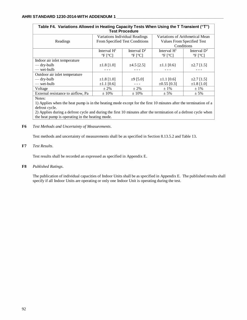
AHRI STANDARD 1230-2014-WITH ADDENDUM 1 ______________________________________________
92
Table F4. Variations Allowed in Heating Capacity Tests When Using the T Transient (“T”) Test Procedure
Readings
Variations Individual Readings
From Specified Test Conditions
Variations of Arithmetical Mean
Values From Specified Test
Conditions
Interval H1
°F [°C]
Interval D2
°F [°C]
Interval H1
°F [°C]
Interval D2
°F [°C]
Indoor air inlet temperature
— dry-bulb — wet-bulb
±1.8 [1.0] - - -
±4.5 [2.5] - - -
±1.1 [0.6} - - -
±2.7 [1.5] - - -
Outdoor air inlet temperature
— dry-bulb
— wet-bulb
±1.8 [1.0]
±1.1 [0.6]
±9 [5.0]
- - -
±1.1 [0.6]
±0.55 [0.3]
±2.7 [1.5]
±1.8 [1.0]
Voltage ± 2% ± 2% ± 1% ± 1%
External resistance to airflow, Pa ± 10% ± 10% ± 5% ± 5%
Notes:
1) Applies when the heat pump is in the heating mode except for the first 10 minutes after the termination of a
defrost cycle. 2) Applies during a defrost cycle and during the first 10 minutes after the termination of a defrost cycle when
the heat pump is operating in the heating mode.
F6 Test Methods and Uncertainty of Measurements.
Test methods and uncertainty of measurements shall be as specified in Section 8.13.5.2 and Table 13. F7 Test Results.
Test results shall be recorded an expressed as specified in Appendix E.
F8 Published Ratings.
The publication of individual capacities of Indoor Units shall be as specified in Appendix E. The published results shall
specify if all Indoor Units are operating or only one Indoor Unit is operating during the test.

______________________________________________ AHRI STANDARD 1230-2014-WITH ADDENDUM 1
93
APPENDIX G. PRESCRIPTIVE METHODOLOGY FOR THE CYCLIC TESTING OF DUCTED SYSTEMS – NORMATIVE
For the purpose of uniformity in the cyclic test requirements of Appendix G, the following test apparatus and conditions shall
be met:
G1 The test apparatus is a physical arrangement of dampers, damper boxes, mixers, thermopile and ducts all properly sealed
and insulated. See Figures G1 through G4 for typical test apparatus. The arrangement and size(s) of the components may be
altered to meet the physical requirements of the unit to be tested.
G2 Dampers and their boxes shall be located outside of the ANSI/ASHRAE Standard 37 pressure measurement locations
in the inlet air and outlet air ducts.
G3 The entire test apparatus shall not have a leakage rate which exceeds 20 cfm [0.01 m³/s ] when a negative pressure of
1.0 in H2O [0.25 kPa] is maintained at the apparatus exit air location.
G4 The apparatus shall be insulated to have "U" value not to exceed 0.04 Btu/(hft2F) [0.23 W/m2 · °C] total.
G5 The air mixer and a 40% maximum open area perforated screen shall be located in the outlet air portion of the apparatus
upstream of the outlet damper. The mixer(s) shall be as described in ANSI/ASHRAE Standard 41.1. The mixing device shall
achieve a maximum temperature spread of 1.5F [0.8 C] across the device. An inlet air mixer is not required.
G6 The temperature difference between inlet air and outlet air shall be measured by a thermopile. The thermopile shall be
constructed of 24 gauge thermocouple wire with 16 junctions at each end. At each junction point the wire insulation shall be
stripped for a length of 1.0 in [25 mm]. The junction of the wires shall have no more than two bonded turns.
G7 The dampers shall be capable of being completely opened or completely closed within a time period not to exceed 10
seconds for each action. Airflow through the equipment being tested should stop within 3 seconds after the airflow measuring
device is de-energized. The air pressure difference (ΔP) at the nozzle shall be within 2% of steady state ΔP within 15 seconds
from the time the air measuring device is re-energized.
G8 Test set up, temperature and electrical measurements must be identical for "C" and "U" tests in order to obtain minimum
error in CD. Electrical measurements shall be taken with an integrating type meter per ANSI/ASHRAE Standard 37 having an
accuracy for all ranges experienced during the cyclic test.
G9 Prior to taking test data, the unit shall be operated at least one hour after achieving dry coil conditions. The drain pan
shall be drained and the drain opening plugged. The drain pan shall be completely dry in order to maximize repeatability and
reproducibility of test results.
G10 For coil only units not employing an enclosure, the coil shall be tested with an enclosure constructed of 1.0 in [25 mm]
fiberglass ductboard with a density of 6 lb/ft3 [100 kg/m3] or an equivalent "R" value. For units with enclosures or cabinets, no
extra insulating or sealing shall be employed.

AHRI STANDARD 1230-2014-WITH ADDENDUM 1 ______________________________________________
94
Fig
ure
G1. T
un
nel
Air
En
thalp
y T
est
Meth
od
Arr
an
gem
en
t

______________________________________________ AHRI STANDARD 1230-2014-WITH ADDENDUM 1
95
Fig
ure
G2. L
oo
p A
ir E
nth
alp
y T
est
Meth
od
Arr
an
gem
en
t

AHRI STANDARD 1230-2014-WITH ADDENDUM 1 ______________________________________________
96
Fig
ure
G3. C
alo
rim
ete
r A
ir E
nth
alp
y T
est
Meth
od
Arr
an
gem
en
t

______________________________________________ AHRI STANDARD 1230-2014-WITH ADDENDUM 1
97
Fig
ure
G4. R
oo
m A
ir E
nth
alp
y T
est
Meth
od
Arr
an
gem
en
t
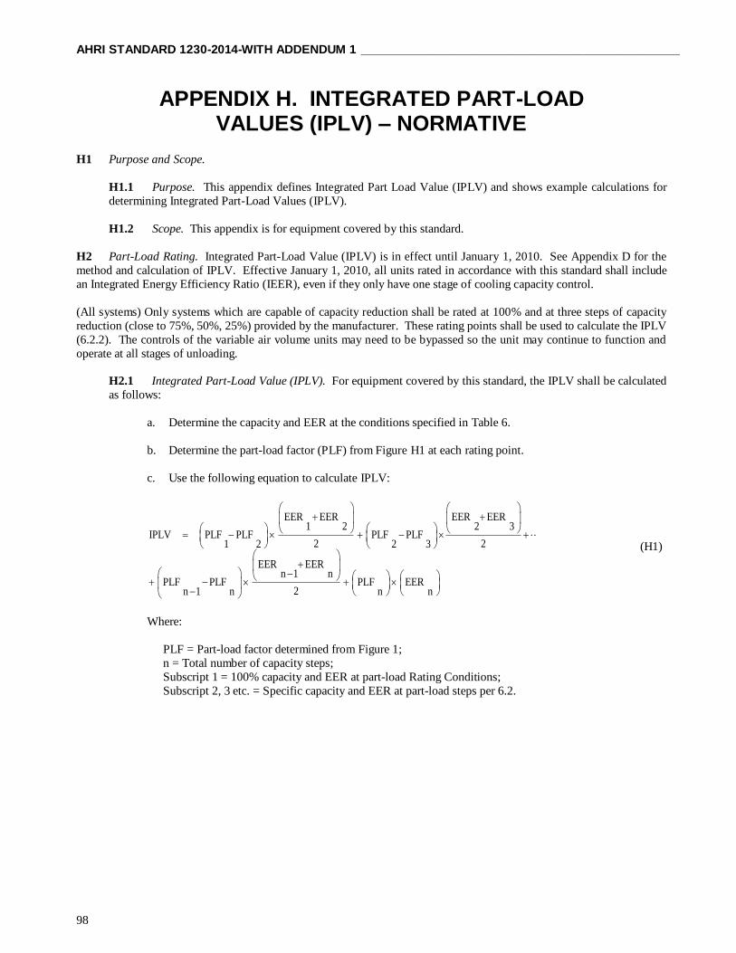
AHRI STANDARD 1230-2014-WITH ADDENDUM 1 ______________________________________________
98
APPENDIX H. INTEGRATED PART-LOAD VALUES (IPLV) – NORMATIVE
H1 Purpose and Scope.
H1.1 Purpose. This appendix defines Integrated Part Load Value (IPLV) and shows example calculations for
determining Integrated Part-Load Values (IPLV).
H1.2 Scope. This appendix is for equipment covered by this standard.
H2 Part-Load Rating. Integrated Part-Load Value (IPLV) is in effect until January 1, 2010. See Appendix D for the
method and calculation of IPLV. Effective January 1, 2010, all units rated in accordance with this standard shall include
an Integrated Energy Efficiency Ratio (IEER), even if they only have one stage of cooling capacity control.
(All systems) Only systems which are capable of capacity reduction shall be rated at 100% and at three steps of capacity
reduction (close to 75%, 50%, 25%) provided by the manufacturer. These rating points shall be used to calculate the IPLV
(6.2.2). The controls of the variable air volume units may need to be bypassed so the unit may continue to function and
operate at all stages of unloading.
H2.1 Integrated Part-Load Value (IPLV). For equipment covered by this standard, the IPLV shall be calculated
as follows:
a. Determine the capacity and EER at the conditions specified in Table 6.
b. Determine the part-load factor (PLF) from Figure H1 at each rating point.
c. Use the following equation to calculate IPLV:
EER EER EER EER1 2 2 3
IPLV PLF PLF PLF PLF2 21 2 2 3
EER EERn 1 n
PLF PLF PLF EER2n 1 n n n
(H1)
Where:
PLF = Part-load factor determined from Figure 1;
n = Total number of capacity steps;
Subscript 1 = 100% capacity and EER at part-load Rating Conditions;
Subscript 2, 3 etc. = Specific capacity and EER at part-load steps per 6.2.

______________________________________________AHRI STANDARD 1230-2014-WITH ADDENDUM 1
99
H3 General Equation and Definitions of Terms.
IPLV = (PLF1 - PLF2 ) + (PLF2 - PLF3 ) + ..……....
+ (PLFn-1 - PLFn ) + (PLFn )(EERn ) (H2)
Where:
PLF = Part-load factor determined from Figure H1;
n = Total number of capacity steps;
Subscript 1 = 100% capacity and EER at part- load Rating Conditions;
Subscript 2, 3, etc. = Specific capacity and EER at part-load steps per 6.3 of this standard.
H4 Calculation Example for a Four Capacity Step System.
H4.1 Assume equipment has four capacity steps as follows:
1 100% (full load)
2 75% of full load
3 50% of full load
4 25% of full load
H4.2 Obtain part-load factors from Figure H1.
H4.3 Obtain EER at each capacity step per 6.3 of AHRI Standard 340/360-2007, formerly ARI Standard 340/360
H4.4 Calculate IPLV using the general equation with:
n = 4
PLF1 = 1.0 EER1 = 8.9
PLF2 = 0.9 EER2 = 7.7
PLF3 = 0.4 EER3 = 7.1 PLF4 = 0.1 EER4 = 5.0
2
EEREER 21 +
2
EEREER 32 +
2
EEREER n1-n +

AHRI STANDARD 1230-2014 WITH ADDENDUM 1 ______________________________________________
100
Enter the above values in Equation H1:
IPLV = (1.0 - 0.9) + (0.9 - 0.4) + (0.4 - 0.1)
+ 0.1 x 5.0 = (0.1 x 8.3) + (0.5 x 7.4) + (0.3 x 6.0) + 0.5 = 0.83 + 3.70 + 1.80 + 0.5
IPLV = 6.8 Btu/(W·h)
To further illustrate the calculation process, see the example in Table H1.
Figure H1. Part-Load Factor Example
2
7.7 + 8.9
2
7.1 + 7.7
2
5.0 + 7.1

AHRI STANDARD 1230-2014 WITH ADDENDUM 1
101
Table H1. Example IPLV Calculation (I-P UNITS)
Capacity
Step
% Full
Load
Cap.2
PLF3
Mfrs.
Part-
Load
EER
Avg.
Part-
Load
EER
PLF Diff.
Avg. EER x
PLF Diff. =
Weighted
Avg.
1
2
3
4
100%
75%
50%
25%
0%
1.0
0.9
0.4
0.1
0.0
8.92
=
7.7
=
7.1
= 5.0
=
8.3
7.4
6.0
5.01
-----
(1.0 - 0.9) =
0.1
(0.9 - 0.4) =
0.5
(0.4 - 0.1) =
0.3
(0.1 - 0.0) =
0.1
8.3 x 0.1 =
7.4 x 0.5 =
6.0 x 0.3 =
5.01 x 0.1 =
Single number
IPLV
0.83
3.70
1.80
0.50
6.834
Notes: 1) For the range between 0% capacity and the last capacity step, use EER of the last capacity step for the
average EER.
2) The 100% capacity and EER are to be determined at the part-load Rating Conditions.
3) Part-Load Factor from Figure H1.
4) Rounded to 6.8

AHRI STANDARD 1230-2014 WITH ADDENDUM 1 ______________________________________________
102
APPENDIX I. UNIT CONFIGURATION FOR STANDARD EFFICIENCY DETERMINATION FOR CAPACITY ABOVE
65,000 BTU/H - INFORMATIVE
I1 Purpose. This appendix is to be used in conjunction with the Tested Combination definition in the standard to
prescribe the requirements for the configuration of a system that is used for determining the Cooling and Heating Capacity at
Standard Rating Conditions and efficiency metrics at Standard Rating Conditions. This will allow for a uniform approach to
determine minimum and other Standard Rating metrics. This appendix is provided for the convenience of users. For official requirements, refer to CFR 431 and DOE’s Enforcement Policy Statement: Commercial HVAC Equipment issued January
30, 2015 (http://energy.gov/gc/downloads/commercial-equipment-testing-enforcement-policies).
I2 Background. The Standard Ratings are intended to be ratings that define the performance of a Basic Model at a defined
set of Rating Conditions. The ratings include the following at Standard Rating Conditions:
I2.1 Standard cooling capacity
I2.2 Standard EER
I2.3 IEER
I2.4 High temperature Heating Capacity
I2.5 High temperature COPH
I2.6 Low temperature Heating Capacity
I2.7 Low temperature COPH
I2.8 Simultaneous Cooling and Heating Efficiency, SCHE
VRF systems are complex systems designed to operate in a building HVAC system and often for non-standard Rating
Conditions and applications. This can include capabilities for enhanced dehumidification capabilities due to local weather conditions and other system related features. This can include system features for overall annual efficiency improvement like
economizers, energy recovery, evaporative cooling, ventilation air requirements, and enhanced IAQ features and filtration.
Many of these features are addressed in building efficiency standards where they compensate for features such as economizers,
energy recovery, fan power, and indoor air quality (IAQ) features.
I3 Configuration Requirements.
I3.1 IAQ Features and Filtration.
I3.1.1 Standard Ratings shall be determined and tested with manufacturer standard, lowest level of air
filtration. For units with no filters, static pressure allowance of 0.08 in H2O shall be added to the minimum
static pressure shown in Table 9. If higher filtration is offered then the unit shall be tested without filters, at an
additional 0.08 in H2O external static pressure.
I3.1.2 UV Lights. A lighting fixture and lamp mounted so that it shines light on the indoor coil, that emits
ultraviolet light to inhibit growth of organisms on the indoor coil surfaces, the condensate drip pan, and/other locations within the equipment. UV lights do not need to be turned on during test.
I3.2 System Features Excluded from Testing. VRF equipment can have many features that enhance the operation of
the unit on an annualized basis. Standards like ASHRAE Standard 90.1 include performance allowances and prescriptive
requirements for many of these features. Standard Ratings shall be determined and tested without the following features
if the manufacturer distributes in commerce an otherwise identical unit that does not have that feature.
I3.2.1 Economizers. An automatic system that enables a cooling system to supply and use outdoor air to
reduce or eliminate the need for mechanical cooling during mild or cold weather. They provide significant
energy efficiency improvements on an annualized basis, but are also a function of regional ambient conditions
and are not considered in the EER or IEER metric.
I3.2.2 Desiccant Dehumidification Components. An assembly that reduces the moisture content of the
Supply Air through moisture transfer with solid or liquid desiccants.

AHRI STANDARD 1230-2014 WITH ADDENDUM 1
103
I3.2.3 Steam/Hydronic Heat Coils. Coils used instead of electric coils to provide primary or supplemental
heating.
I3.2.4 Coated Coils. An indoor coil or outdoor coil whose entire surface, including the entire surface of
both fins and tubes, is covered with a thin continuous non-porous coating to reduce corrosion. A coating for
this purpose will be defined based on what is deemed to pass ANSI/ASTM B117 or ANSI/ASTM G85 test of
500 hours or more.
I3.3 Customer System Features.
I3.3.1 Hail Guards. A grille or similar structure mounted to the outside of the unit covering the outdoor
coil to protect the coil from hail, flying debris and damage from large objects. Hail guards shall be removed
during testing, if present.
I3.3.2 Snow/Wind Guards. A baffle and or ducting mounted to the air intake and discharge of the Outdoor
Unit.. Snow/Wind guards shall be removed during testing, if present.
I3.3.3 Grille Options. Various grille options can be used for airflow direction or customer preference.
Equipment should be tested with standard grilles.
I3.4 Dampers. Standard Ratings shall be determined and tested without the following dampers. If the sample has
outdoor air or exhaust air dampers while testing, they shall be fully sealed to prevent operation.
I3.4.1 Fresh Air Dampers. An assembly with dampers and means to set the damper position in a closed
and one open position to allow air to be drawn into the equipment when the indoor fan is operating. For the
Standard Ratings, fresh air dampers shall be fully sealed.
I3.4.2 Low Ambient Cooling Dampers. An assembly with dampers and means to set the dampers in a
position to recirculate the warmer condenser discharge air to allow for reliable operation at low outdoor ambient
conditions. Low ambient cooling dampers shall be removed for testing.

AHRI STANDARD 1230-2014 WITH ADDENDUM 1 ______________________________________________
104
APPENDIX J. DEVELOPMENT OF SUPPLEMENTAL TESTING INSTRUCTIONS FOR SET-UP AND TESTING OF
VRF MULTI-SPLIT SYSTEMS - INFORMATIVE
J1 Purpose. The purpose of this appendix is to provide guidance for manufacturers to develop the supplemental testing
instructions to better detail the manufacturer’s requirements for a proper installation of the VRF system in the testing laboratory.
This will allow for a uniform approach to determine minimum and other Standard Rating metrics. For official requirements,
refer to 10 CFR 429 and 431. This appendix applies to all air-source and all water-source VRF multi-split systems.
Note: The intent of the supplemental testing instructions PDF is to describe the layout of a system set-up in the laboratory. In
the event of conflicting Instructions regarding the set-up of the system, outdoor unit installation instructions prevail, followed
by the outdoor unit label, followed by the indoor unit installation instructions, followed by the supplemental PDF testing
instructions.
J2 Background. Manufacturers are required to certify ratings to the Department of Energy. In 10 CFR 429.43 Commercial
heating, ventilating, air conditioning (HVAC) equipment) it is stated:
“(4) Pursuant to § 429.12(b)(13 a certification report must include supplemental information submitted in PDF format. The
equipment-specific, supplemental information must include any additional testing and testing set up instructions
(e.g., charging instructions) for the basic model; identification of all special features that were included in rating the basic
model; and all other information (e.g., operational codes or component settings) necessary to operate the basic model under
the required conditions specified by the relevant test procedure. A manufacturer may also include with a certification report
other supplementary items in PDF format (e.g., manuals) for DOE consideration in performing testing under subpart C of this
part. The equipment-specific, supplemental information must include at least the following:
(v) Variable refrigerant flow multi-split air conditioners with cooling capacity less than 65,000 Btu/h (3-phase): The
Nominal Cooling Capacity in British thermal units per hour (Btu/h); outdoor unit(s) and indoor units identified in the tested
combination; components needed for heat recovery, if applicable; rated airflow in standard cubic feet per minute (SCFM) for
each indoor unit; water flow rate in gallons per minute (gpm) for water-source units only; rated static pressure in inches of
water; compressor frequency set points; required dip switch/control settings for step or variable components; a statement whether the model will operate at test conditions without manufacturer programming; any additional testing instructions, if
applicable; if a variety of motors/drive kits are offered for sale as options in the basic model to account for varying installation
requirements, the model number and specifications of the motor (to include efficiency, horsepower, open/closed, and number
of poles) and the drive kit, including settings, associated with that specific motor that were used to determine the certified
rating; and which, if any, special features were included in rating the basic model. Additionally, upon DOE request, the
manufacturer must provide a layout of the system set-up for testing including charging instructions consistent with the
installation manual.
(vi) Variable refrigerant flow multi-split heat pumps with cooling capacity less than 65,000 Btu/h (3-phase): The Nominal
Cooling Capacity in British thermal units per hour (Btu/h); rated heating capacity in British thermal units per hour (Btu/h);
outdoor unit(s) and indoor units identified in the tested combination; components needed for heat recovery, if applicable; rated
airflow in standard cubic feet per minute (scfm) for each indoor unit; water flow rate in gallons per minute (gpm) for water-
source units only; rated static pressure in inches of water; compressor frequency set points; required dip switch/control settings
for step or variable components; a statement whether the model will operate at test conditions without manufacturer
programming; any additional testing instructions, if applicable; if a variety of motors/drive kits are offered for sale as options
in the basic model to account for varying installation requirements, the model number and specifications of the motor (to include efficiency, horsepower, open/closed, and number of poles) and the drive kit, including settings, associated with that
specific motor that were used to determine the certified rating; and which, if any, special features were included in rating the
basic model. Additionally, upon DOE request, the manufacturer must provide a layout of the system set-up for testing including
charging instructions consistent with the installation manual.
(vii) Variable refrigerant flow multi-split air conditioners with cooling capacity greater than or equal to 65,000 Btu/h:
The Nominal Cooling Capacity in British thermal units per hour (Btu/h); outdoor unit(s) and indoor units identified in the tested
combination; components needed for heat recovery, if applicable; rated airflow in standard cubic feet per minute (SCFM) for
each indoor unit; water flow rate in gallons per minute (gpm) for water-source units only; rated static pressure in inches of
water; compressor frequency set points; required dip switch/control settings for step or variable components; a statement
AHRI STANDARD 1230-2014 WITH ADDENDUM 1
105
whether the model will operate at test conditions without manufacturer programming; any additional testing instructions if
applicable; if a variety of motors/drive kits are offered for sale as options in the basic model to account for varying installation
requirements, the model number and specifications of the motor (to include efficiency, horsepower, open/closed, and number
of poles) and the drive kit, including settings, associated with that specific motor that were used to determine the certified
rating; and which, if any, special features were included in rating the basic model. Additionally, upon DOE request, the
manufacturer must provide a layout of the system set-up for testing including charging instructions consistent with the
installation manual.
(viii) Variable refrigerant flow multi-split heat pumps with cooling capacity greater than or equal to 65,000 Btu/h: The
Nominal Cooling Capacity in British thermal units per hour (Btu/h); rated heating capacity in British thermal units per hour
(Btu/h); outdoor unit(s) and indoor units identified in the tested combination; components needed for heat recovery, if
applicable; rated airflow in standard cubic feet per minute (scfm) for each indoor unit; water flow rate in gallons per minute
(gpm) for water-source units only; rated static pressure in inches of water; compressor frequency set points; required dip switch/control settings for step or variable components; a statement whether the model will operate at test conditions without
manufacturer programming; any additional testing instructions if applicable; if a variety of motors/drive kits are offered for
sale as options in the basic model to account for varying installation requirements, the model number and specifications of the
motor (to include efficiency, horsepower, open/closed, and number of poles) and the drive kit, including settings, associated
with that specific motor that were used to determine the certified rating; and which, if any, special features were included in
rating the basic model. Additionally, upon DOE request, the manufacturer must provide a layout of the system set-up for testing
including charging instructions consistent with the installation manual.
(ix) Water source variable refrigerant flow heat pumps: The Nominal Cooling Capacity in British thermal units per hour
(Btu/h); rated heating capacity in British thermal units per hour (Btu/h); rated airflow in standard cubic feet per minute (scfm)
for each indoor unit; water flow rate in gallons per minute (gpm); rated static pressure in inches of water; refrigeration charging
instructions (e.g., refrigerant charge, superheat and/or subcooling temperatures); frequency set points for variable speed
components (e.g., compressors, VFDs), including the required dip switch/control settings for step or variable components; a
statement whether the model will operate at test conditions without manufacturer programming; any additional testing
instructions if applicable; if a variety of motors/drive kits are offered for sale as options in the basic model to account for
varying installation requirements, the model number and specifications of the motor (to include efficiency, horsepower, open/closed, and number of poles) and the drive kit, including settings, associated with that specific motor that were used to
determine the certified rating; and which, if any, special features were included in rating the basic model. Additionally, upon
DOE request, the manufacturer must provide a layout of the system set-up for testing including charging instructions consistent
with the installation manual.”
J4 Supplemental Testing Instructions PDF. VRF systems manufacturers are required to develop and submit supplemental
testing instructions PDFs for each basic model to ensure that their VRF systems can be properly installed in the laboratory and
tested by a third party testing organization. In addition to requirements listed in 10 CFR 429.43, VRF systems manufacturer
should consider including the following information/instructions in their Supplemental Testing Instructions PDF for each basic
model:
J4.1 System Installation Manual references
J4.2 ODU set-up especially for twinned Outdoor Unit modules
J4.3 Set-up for IDUs in the indoor side(s) of the test room
J4.4 Allocation of IDU’s for SCHE testing (For heat recovery systems, identify the split of the IDUs between heating
and cooling) J4.5 Piping diagram
J4.6 Power wiring diagram
J4.7 Control wiring diagram
J4.8 System control device
J4.9 Define which ODUs/compressors will be operating for each test (for systems ≥ 65,000 Btu/h)
J4.10 Define which IDUs will be operating for each test (for systems < 65,000 Btu/h)
J4.11 Airflow settings per each indoor unit
J4.12 System break-in requirements
J4.13 Liquid flow rate per module (applicable for water-source system)
J4.14 Identify if the oil recovery occurs in less than two hours
J5 Examples of System Layout Figures.

AHRI STANDARD 1230-2014 WITH ADDENDUM 1 ______________________________________________
106
Figure J1. Typical Wiring Diagram for Heat Pump
Figure J2. Typical Wiring Diagram for Heat Recovery

AHRI STANDARD 1230-2014 WITH ADDENDUM 1
107
Figure J3. Typical Piping Diagram for Heat Recovery
Table J1. Typical Piping for Heat Recovery
System
Model Number
Duct/Non-ducted
Indoor Unit
#1 #2 #3 #4 #5 #6 #7 #8 #9 #10 #11 #12
PIPE
A (ft)
PIPE
#1 (ft)
PIPE
#2 (ft)
PIPE
#3 (ft)
PIPE
#4 (ft)
PIPE
#5 (ft)
PIPE
#6 (ft)
PIPE
#7 (ft)
PIPE
#8 (ft)
PIPE
#9 (ft)
PIPE
#10 (ft)
PIPE
#11 (ft)
PIPE
#12 (ft)
Outdoor model
#1
Ducted
Liquid or
High pressure
side
Size
Length 12 13 13 13 13 13 13 13 13 13 13 13 13
Vapor or
Low pressure
side
Size
Length 12 13 13 13 13 13 13 13 13 13 13 13 13
Non-Ducted
Liquid or High
pressure
side
Size - - - -
Length 37 13 13 13 13 13 13 13 13 - - - -
Vapor or Low
pressure side
Size - - - -
Length 37 13 13 13 13 13 13 13 13 - - - -
Outdoor model
#2
Ducted
Liquid or
High
pressure side
Size - -
Length 37 13 13 13 13 13 13 13 13 13 13 - -
Vapor or
Low pressure
side
Size - -
Length 37 13 13 13 13 13 13 13 13 13 13 - -
Non-Ducted
Liquid or
High pressure
side
Size -
Length 87 13 13 13 13 13 13 13 13 13 13 13 -
Vapor or Low
pressure side
Size -
Length 87 13 13 13 13 13 13 13 13 13 13 13 -
Hea
t R
eco
ver
y
Ref
rig
eran
t D
istr
ibu
tor


