Canadian Wood Council G063 Fire Resistance Tools and Information for Wood-Frame Buildings Ineke Van Zeeland, M.Eng., Senior Manager, Codes & Standards – Fire & Acoustics, Canadian Wood Council November 24, 2015
Transcript
Canadian Wood CouncilG063
Fire Resistance Tools and Information for Wood-Frame Buildings
Ineke Van Zeeland, M.Eng., Senior Manager, Codes & Standards – Fire & Acoustics, Canadian Wood Council
November 24, 2015
Credit(s) earned on completion of this course will be reported to AIA CES for AIA members. Certificates of Completion for both AIA members and non-AIA members are available upon request.
This course is registered with AIA
CES for continuing professional education. As such, it does not include content that may be deemed or construed to be an approval or endorsement by the AIA of any material of construction or any method or manner ofhandling, using, distributing, or dealing in any material or product._______________________________________Questions related to specific materials, methods, and services will be addressed at the conclusion of this presentation.
This seminar will discuss various sources of information and tools that may be used to develop solutions to meet the building code’s fire‐resistance rating requirements for wood buildings, including the 2015 revisions to the Component Additive Method and a new Annex B, entitled “Fire resistance of large cross‐section wood elements,” in CSA O86 Engineering Design in Wood.
CourseDescription
LearningObjectives
• The speaker will present the various sources of information and tools that may be used to develop solutions to meet the building code’s fire‐resistance rating requirements for wood buildings.
• The presenter will discuss the 2015 revisions to the Component Additive Method.• The presenter will discuss the new Annex B, entitled “Fire resistance of large cross‐
section wood elements,” in CSA O86 Engineering Design in Wood.• Participants will understand how to develop solutions that meet the building code’s fire‐
resistance rating requirements for wood buildings.
Key learning points:
5
Fire Resistance
Fire Resistance
fire resistance, n—the ability of a material, product, or assembly to withstand fire or give protection from it for a period of time. (ASTM E 176-15 Standard Terminology of Fire Standards)
1.4.1.2: "...the time in minutes or hours that a material or assembly of materials will withstand the passage of flame and the transmission of heat when exposed to fire under specified conditions of test and performance criteria, or as determined by extension or interpretation of information derived from that test and performance as prescribed in this Code."
OBC 2015 - Division A - Part 1“Fire-resistance rating”
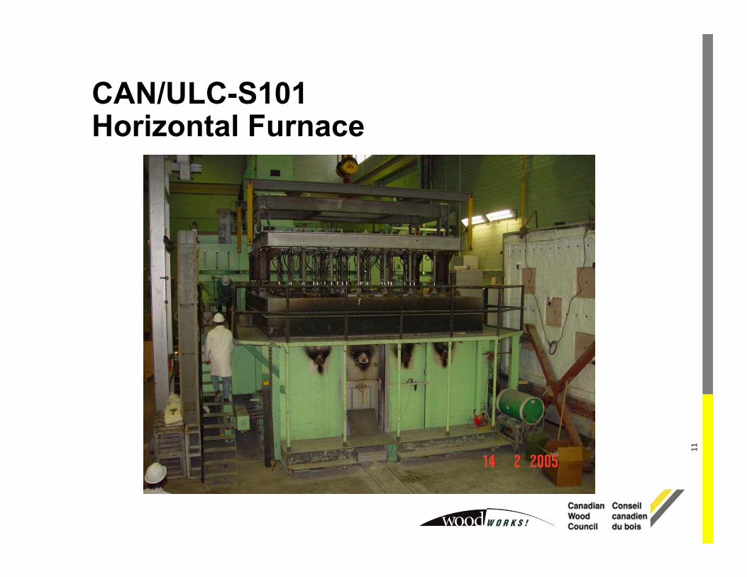
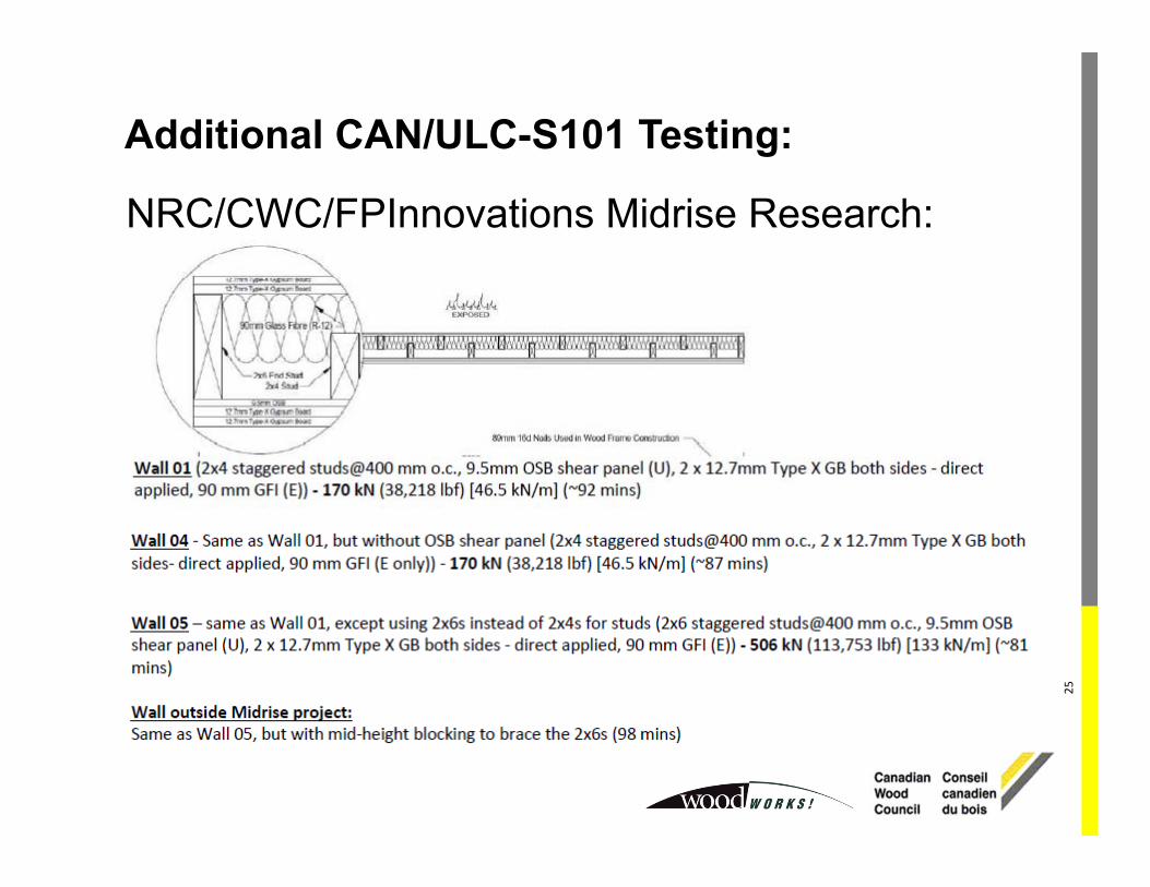
Sentence 3.1.7.1.(1): CAN/ULC-S101 - Fire Endurance Tests of Building Construction and Materials
Empirical Calculation Methods: CAM – NEW 2015 NBC Appendix D-2.3.
Wood Wall Assemblies
Membrane Members Insulation Total FRR*Description Assigned
time (min) Description Assigned time (min) Description Assigned time
(min)
Loadbearing2 layers of
12.7 mm Type X Gypsum Board
50
Wood Studs @ 400 mm o.c. 20
RFI 15 85CFI – dry-blown 10 80
None & GFI 0 70
Wood Studs @ 600 mm o.c. 15
RFI 15 80CFI – dry-blown 10 75
None & GFI 0 65
Non-loadbearing2 layers of
12.7 mm Type X Gypsum Board
80
Wood Studs @ 400 mm o.c. 20
RFI 15 115GFI 5 105
None 0 100
Wood Studs @ 600 mm o.c. 15
RFI 15 110GFI 5 100
None 0 95
Empirical Calculation Methods: CAM – NEW 2015 NBC Appendix D-2.3.
Wood Wall Assemblies
Membrane MembersTotalFRR*Description
Assigned time(min)
DescriptionAssigned
time(min)
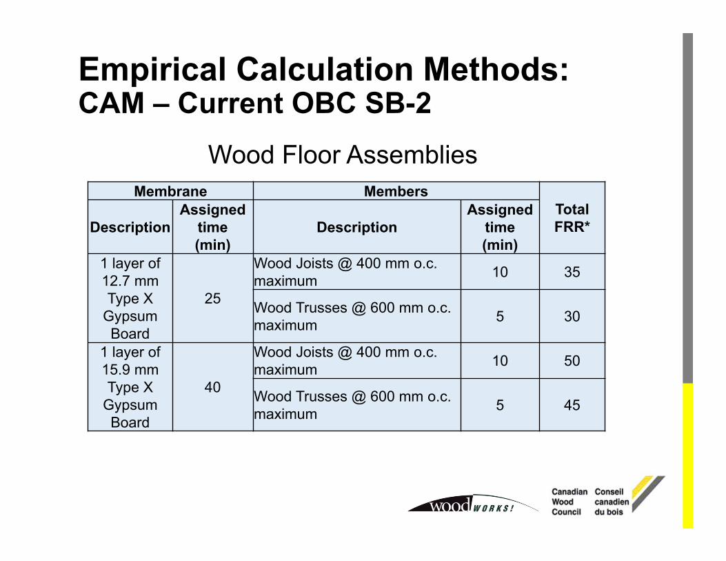
1 layer of 12.7 mm Type X
Gypsum Board
25
Wood Joists @ 400 mm o.c. maximum 10 35
Wood Trusses @ 600 mm o.c. maximum 5 30
1 layer of 15.9 mm Type X
Gypsum Board
40
Wood Joists @ 400 mm o.c. maximum 10 50
Wood Trusses @ 600 mm o.c. maximum 5 45
Wood Floor Assemblies
Empirical Calculation Methods: CAM – Current OBC SB-2
Membrane Members Insulation ToppingTotalFRRDescription
ResilientMetal
Channels
Assigned time(min)
DescriptionAssigned
time(min)
DescriptionAssigned
time(min)
DescriptionAssigned
time(min)
1 layers of 12.7 mm Type X
Gypsum Board
Spaced ≤ 400 mm o.c. 25
Wood Joists, Trusses,
I-joists @ 600 mm o.c.
maximum
10
MFI (rock or slag) or
CFI (wet-sprayed)
5
None or Gypsum-concrete 0 40
Concrete 5 45
None or GFI 0None or Gypsum-
concrete 0 35
Concrete 5 40
1 layer of 15.9 mm Type X
Gypsum Board
Spaced ≤ 400 mm o.c. 40
Wood Joists, Trusses,
I-joists @ 600 mm o.c.
maximum
10
MFI (rock or slag) or
CFI (wet-sprayed)
5
None or Gypsum-concrete 0 55
Concrete 5 60
None or GFI 0None or Gypsum-
concrete 0 50
Concrete 5 55
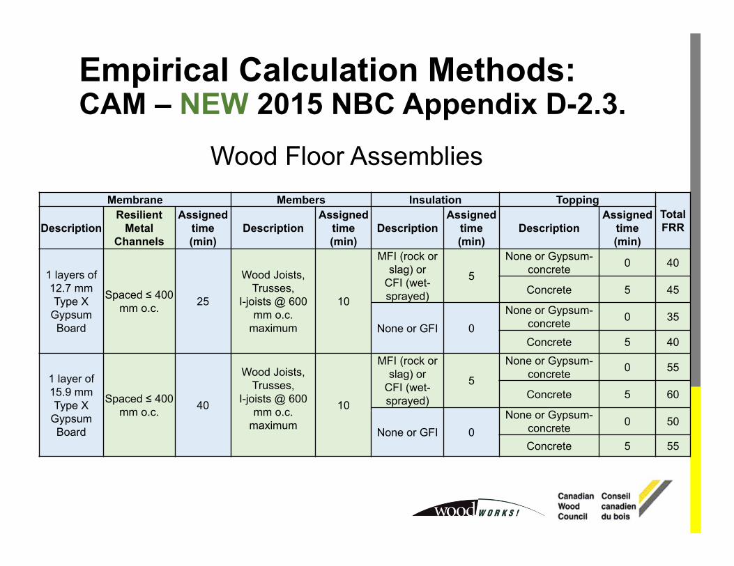
Empirical Calculation Methods: CAM – NEW 2015 NBC Appendix D-2.3.
Wood Floor Assemblies
Membrane Members Insulation ToppingTotalFRRDescription
ResilientMetal
Channels
Assigned time(min)
DescriptionAssigned
time(min)
DescriptionAssigned
time(min)
DescriptionAssigned
time(min)
2 layers of 12.7 mm Type X
Gypsum Board
Spaced ≤ 400 mm o.c.(or direct applied to
members ≤ 400 mm o.c.)
50
Wood Joists, Trusses, I-joists @ 600 mm o.c. maximum
10
RFI or CFI (wet-
sprayed)5
None or Gypsum-concrete 0 65
Concrete 5 70
None or GFI 0None or Gypsum-
concrete 0 60
Concrete 5 65
2 layers of 12.7 mm Type X
Gypsum Board
Spaced ≤ 600 mm o.c.(or direct applied)
45
Wood Joists, Trusses, I-joists @ 600 mm o.c. maximum
10
RFI or CFI (wet-
sprayed)5
None or Gypsum-concrete 0 60
Concrete 5 65
None or GFI 0None or Gypsum-
concrete 0 55
Concrete 5 60
2 layer of 15.9 mm Type X
Gypsum Board
Spaced ≤ 600 mm o.c.(or direct applied)
60
Wood Joists, Trusses, I-joists @ 600 mm o.c. maximum
10
RFI or CFI (wet-
sprayed)5
None or Gypsum-concrete 0 75
Concrete 5 80
None or GFI 0None or Gypsum-
concrete 0 70
Concrete 5 75
Empirical Calculation Methods: CAM – NEW 2015 NBC Appendix D-2.3.
Wood Floor Assemblies
37
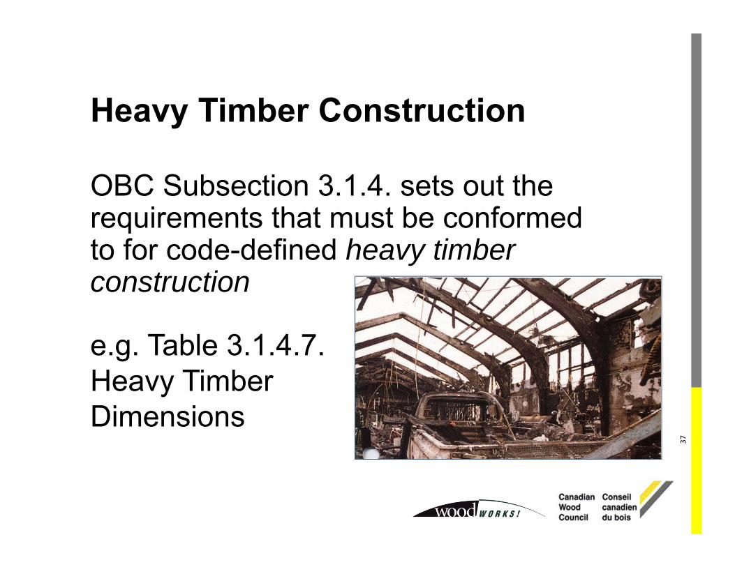
Heavy Timber Construction
OBC Subsection 3.1.4. sets out the requirements that must be conformed to for code-defined heavy timber construction
e.g. Table 3.1.4.7. Heavy Timber Dimensions
38
Division B - Article 3.1.4.6.Heavy Timber Construction Alternative:3.1.4.6.(1): If combustible construction is permitted and is not required to have a fire-resistance rating of more than 45 min, heavy timber construction is permitted to be used.
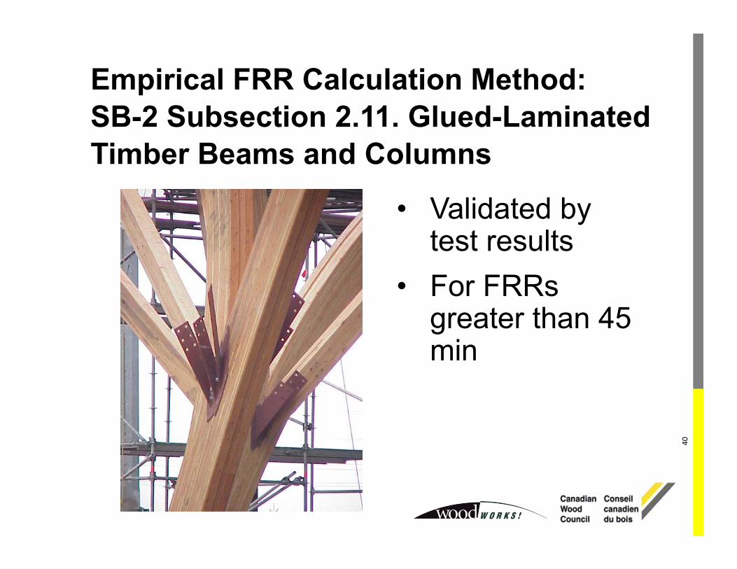
Empirical FRR Calculation Methods: Mass Timber Beams and Columns
Additional Information:•American Wood Council (www.awc.ca)•DCA 2 - Design of Fire-Resistive Exposed Wood Members
•TR10 - Calculating the Fire Resistance of Exposed Wood Members
5.6 Fire resistanceWhere applicable, design for fire resistance shall be in accordance with the NBCC.Note: See Annex B for a methodology that provides useful information in the development of a proposal for an alternative solution to meet the objectives of the NBCC.
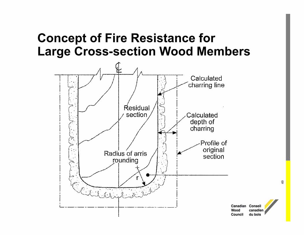
Empirical FRR Calculation Methods: CSA O86-2014 Large Cross-section Wood Elements (Mass Timber)
Empirical FRR Calculation Methods: CSA O86-2014 Large Cross-section Wood Elements (Mass Timber)
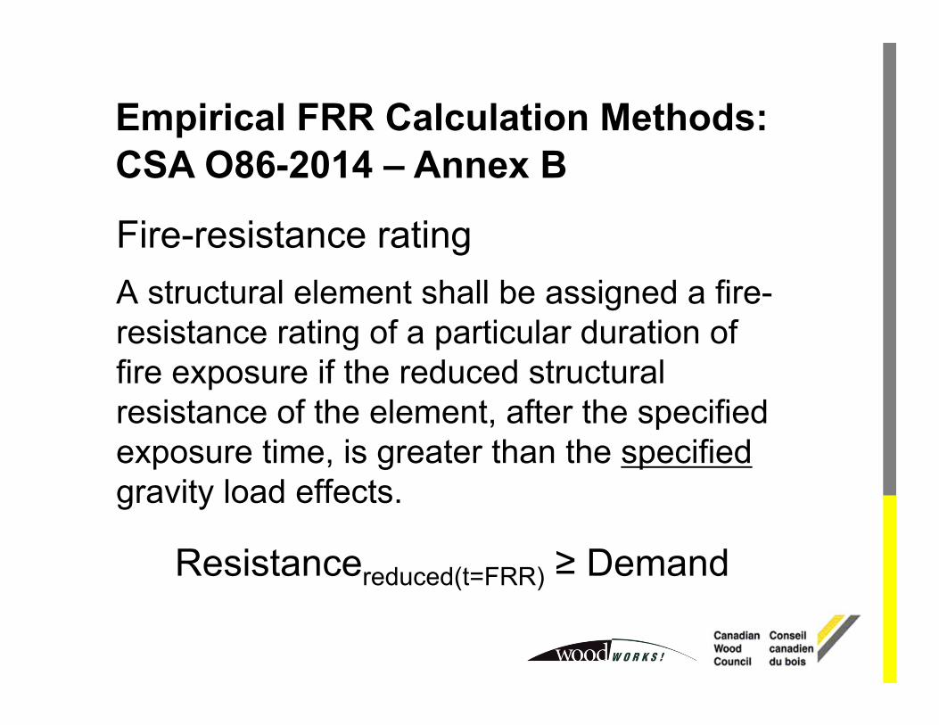
Empirical FRR Calculation Methods: CSA O86-2014 – Annex B
Fire-resistance ratingA structural element shall be assigned a fire-resistance rating of a particular duration of fire exposure if the reduced structural resistance of the element, after the specified exposure time, is greater than the specifiedgravity load effects.
Resistancereduced(t=FRR) ≥ Demand
Empirical FRR Calculation Methods: CSA O86-2014 – Annex B
Surfaces initially protected by gypsum board• one layer of 12.7 mm Type X ‒ 15 min• one layer of 15.9 mm Type X ‒ 30 min • two layers of 15.9 mm Type X ‒ 60 min
Connections• Limited information at this time• AWC’s Technical Report 10 • Eurocode 5: Part 1-2
Empirical FRR Calculation Methods: CSA O86-2014 – Annex B
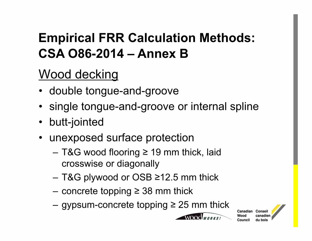
Wood decking• double tongue-and-groove• single tongue-and-groove or internal spline• butt-jointed• unexposed surface protection
– T&G wood flooring ≥ 19 mm thick, laid crosswise or diagonally
– T&G plywood or OSB ≥12.5 mm thick– concrete topping ≥ 38 mm thick– gypsum-concrete topping ≥ 25 mm thick
Empirical FRR Calculation Methods: CSA O86-2014 – Annex B
57
Cross-Laminated Timber (CLT)
Empirical FRR Calculation Methods: CSA O86-2016 Supplement – Annex B
Additional Resources:• Fire Safety Design in Buildings, Canadian Wood Council,
1996 (free PDF - www.cwc.ca).
• Janssens, M., and Douglas, Brad; Chapter 7 - Wood and Wood Products, Handbook of Building Materials for FireProtection, McGraw-Hill, 2004.
• White, Robert H.; Section 4, Chapter 11 - AnalyticalMethods for Determining Fire Resistance of TimberMembers, The SFPE Handbook of Fire Protection Engineering, Society of Fire Protection Engineering, 4th Edition, 2008.
• White, Robert H., et al.; Wood Handbook, Chapter 18: FireSafety of Wood Construction, 2010 (free PDF -www.fpl.fs.fed.us).
• SP Report 2010:19, Fire Safety in Timber Buildings: Technical Guideline, 2010.
This concludes The American Institute of Architects Continuing Education Systems Course